KR20120095557A - Trailing arm bush for vehicle - Google Patents
Trailing arm bush for vehicle Download PDFInfo
- Publication number
- KR20120095557A KR20120095557A KR1020110014945A KR20110014945A KR20120095557A KR 20120095557 A KR20120095557 A KR 20120095557A KR 1020110014945 A KR1020110014945 A KR 1020110014945A KR 20110014945 A KR20110014945 A KR 20110014945A KR 20120095557 A KR20120095557 A KR 20120095557A
- Authority
- KR
- South Korea
- Prior art keywords
- inner pipe
- diameter portion
- vehicle
- pipe
- trailing arm
- Prior art date
Links
Images


Classifications
-
- B—PERFORMING OPERATIONS; TRANSPORTING
- B60—VEHICLES IN GENERAL
- B60G—VEHICLE SUSPENSION ARRANGEMENTS
- B60G7/00—Pivoted suspension arms; Accessories thereof
- B60G7/04—Buffer means for limiting movement of arms
-
- B—PERFORMING OPERATIONS; TRANSPORTING
- B60—VEHICLES IN GENERAL
- B60G—VEHICLE SUSPENSION ARRANGEMENTS
- B60G11/00—Resilient suspensions characterised by arrangement, location or kind of springs
- B60G11/18—Resilient suspensions characterised by arrangement, location or kind of springs having torsion-bar springs only
-
- B—PERFORMING OPERATIONS; TRANSPORTING
- B60—VEHICLES IN GENERAL
- B60G—VEHICLE SUSPENSION ARRANGEMENTS
- B60G15/00—Resilient suspensions characterised by arrangement, location or type of combined spring and vibration damper, e.g. telescopic type
-
- B—PERFORMING OPERATIONS; TRANSPORTING
- B60—VEHICLES IN GENERAL
- B60G—VEHICLE SUSPENSION ARRANGEMENTS
- B60G15/00—Resilient suspensions characterised by arrangement, location or type of combined spring and vibration damper, e.g. telescopic type
- B60G15/02—Resilient suspensions characterised by arrangement, location or type of combined spring and vibration damper, e.g. telescopic type having mechanical spring
- B60G15/06—Resilient suspensions characterised by arrangement, location or type of combined spring and vibration damper, e.g. telescopic type having mechanical spring and fluid damper
-
- B—PERFORMING OPERATIONS; TRANSPORTING
- B60—VEHICLES IN GENERAL
- B60G—VEHICLE SUSPENSION ARRANGEMENTS
- B60G7/00—Pivoted suspension arms; Accessories thereof
-
- B—PERFORMING OPERATIONS; TRANSPORTING
- B60—VEHICLES IN GENERAL
- B60G—VEHICLE SUSPENSION ARRANGEMENTS
- B60G7/00—Pivoted suspension arms; Accessories thereof
- B60G7/02—Attaching arms to sprung part of vehicle
Landscapes
- Engineering & Computer Science (AREA)
- Mechanical Engineering (AREA)
- Vehicle Body Suspensions (AREA)
Abstract
Description
본 발명은 차량의 후륜 현가장치를 구성하는 트레일링암을 차체에 연결하는 매개체로 사용되는 부시에 관한 것으로서, 보다 상세하게는 부시의 구조에 관한 기술이다.BACKGROUND OF THE
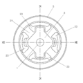
도 1 내지 도 3은 종래 차량의 트레일링암 부시의 구조를 도시한 것으로서, 내측파이프(500)와 외측파이프(502) 사이에 고무재질의 완충부재(504)가 구비된 구조를 가지고 있으며, 상기 완충부재(504)는 내측파이프(500)와 외측파이프(502) 사이를 연결하는 부위로 이루어진 레그(506)와, 상기 내측파이프(500)와 외측파이프(502) 사이에 형성된 갭(508) 등이 일체로 구비된 구조이다.
1 to 3 illustrate a structure of a trailing arm bush of a conventional vehicle, and has a structure in which a
상기한 바와 같은 트레일링암 부시는 차량의 핸들링, 승차감, 로드노이즈에 영향을 주는 바, 트레일링암 부시의 차량 좌우방향을 따른 강성이 높은 것이 차량 핸들링에 유리하며, 차량 전후 방향 강성이 작고 변형량이 큰 것이 승차감에 유리하며, 차량 상하방향 강성이 작은 것이 로드노이드 저감에 유리한 특성이 있다.
As described above, the trailing arm bush affects the handling, ride comfort, and road noise of the vehicle. The trailing arm bush has a high rigidity along the right and left directions of the trailing arm bush, which is advantageous for the vehicle handling. It is advantageous to ride comfort, and the small vertical rigidity of the vehicle has an advantage to reduce the roadnode.
상기한 바와 같은 특성들을 감안하여 트레일링암 부시의 형상을 결정하여 차량에 적용하게 되는데, 트레일링암 부시의 전후방향 또는 상하방향 강성 및 변형량은 부시의 크기로 튜닝이 가능하지만, 차량의 좌우방향 즉, 횡방향의 강성값은 기본적으로 트레일링암 부시가 전단형으로 변형이 이루어지기 때문에 강성의 증대에 한계가 있어서, 차량의 핸들링 성능 최적화가 미흡한 경향이 있다.In consideration of the characteristics described above, the shape of the trailing arm bush is determined and applied to the vehicle. The stiffness and deformation of the trailing arm bush in the front and rear or up and down directions can be tuned to the size of the bush, Since the stiffness value in the lateral direction is basically limited in increasing the rigidity because the trailing arm bush is deformed in the shear type, the handling performance of the vehicle tends to be insufficient.
본 발명은 상기한 바와 같은 문제점을 해결하기 위하여 안출된 것으로서, 차량 전후방향 및 상하방향의 강성을 적절한 수준으로 형성하여 차량의 승차감과 로드노이즈 성능을 향상시킬 수 있도록 함은 물론, 차량 횡방향의 강성을 충분히 확보할 수 있도록 함으로써, 차량의 핸들링 성능도 크게 향상시킬 수 있도록 한 차량의 트레일링암 부시를 제공함에 그 목적이 있다.The present invention has been made in order to solve the above problems, to form a rigidity of the vehicle front and rear direction and up and down direction to an appropriate level to improve the ride comfort and road noise performance of the vehicle, as well as the transverse direction of the vehicle It is an object of the present invention to provide a trailing arm bush of a vehicle that can sufficiently improve the handling performance of the vehicle by ensuring sufficient rigidity.
상기한 바와 같은 목적을 달성하기 위한 본 발명 차량의 트레일링암 부시는The trailing arm bush of the vehicle of the present invention for achieving the above object is
중앙에 직선적으로 관통된 중공부를 구비하고, 상기 중공부의 축방향을 따라 단면의 외곽형상이 변화하도록 형성된 인너파이프와;An inner pipe having a hollow portion linearly penetrated at the center thereof and configured to change an outer shape of a cross section along an axial direction of the hollow portion;
상기 인너파이프의 외측에 위치하며, 상기 인너파이프의 변화하는 외곽형상에 상응하도록 단면형상이 변화하도록 형성되어, 상기 중공부의 축방향을 따른 투영면의 일부가 상기 인너파이프의 투영면 일부와 중첩되도록 형성된 아웃터파이프와;Located outside the inner pipe and formed so that the cross-sectional shape is changed to correspond to the changing outer shape of the inner pipe, the outer portion formed so that a portion of the projection surface along the axial direction of the hollow portion overlaps with a portion of the projection surface of the inner pipe With pipes;
상기 중첩되는 투영면들을 형성하게 되는 상기 인너파이프와 아웃터파이프의 부분들 사이를 포함하여 상기 인너파이프와 아웃터파이프 사이에 개재된 완충부재;A cushioning member interposed between the inner pipe and the outer pipe including portions of the inner pipe and the outer pipe forming the overlapping projection surfaces;
를 포함하여 구성된 것을 특징으로 한다.And a control unit.
본 발명은 차량 전후방향 및 상하방향의 강성을 적절한 수준으로 형성하여 차량의 승차감과 로드노이즈 성능을 향상시킬 수 있도록 함은 물론, 차량 횡방향의 강성을 충분히 확보할 수 있도록 함으로써, 차량의 핸들링 성능도 크게 향상시킬 수 있도록 한다.The present invention forms the rigidity of the vehicle front and rear and up and down direction to an appropriate level to improve the ride comfort and road noise performance of the vehicle, as well as to ensure sufficient rigidity in the transverse direction of the vehicle, the handling performance of the vehicle Also greatly improves.
도 1 내지 도 3은 종래 기술에 따른 트레일링암 부시의 구조를 설명한 도면,
도 4는 본 발명에 따른 트레일링암 부시의 구조를 도시한 도면,
도 5와 도 6은 각각 도 4의 아웃터파이프와 인너파이프를 도시한 도면,
도 7은 도 4의 후방에서 관측한 도면,
도 8은 도 7의 Ⅷ-Ⅷ선 단면도,
도 9는 도 7의 Ⅸ-Ⅸ선 단면도이다.1 to 3 is a view for explaining the structure of the trailing arm bush according to the prior art,
4 is a view showing a structure of a trailing arm bush according to the present invention;
5 and 6 are views illustrating the outer pipe and the inner pipe of FIG. 4, respectively.
7 is a view observed from the rear of FIG. 4;
8 is a cross-sectional view taken along line VII-VII of FIG. 7;
FIG. 9 is a cross-sectional view taken along line VII-VII of FIG. 7.
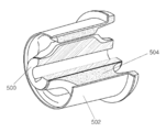
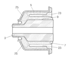
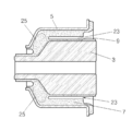
도 4 내지 도 9를 참조하면, 본 발명 실시예는 중앙에 직선적으로 관통된 중공부(1)를 구비하고, 상기 중공부(1)의 축방향을 따라 단면의 외곽형상이 변화하도록 형성된 인너파이프(3)와; 상기 인너파이프(3)의 외측에 위치하며, 상기 인너파이프(3)의 변화하는 외곽형상에 상응하도록 단면형상이 변화하도록 형성되어, 상기 중공부(1)의 축방향을 따른 투영면의 일부가 상기 인너파이프(3)의 투영면 일부와 중첩되도록 형성된 아웃터파이프(5)와; 상기 중첩되는 투영면들을 형성하게 되는 상기 인너파이프(3)와 아웃터파이프(5)의 부분들 사이를 포함하여 상기 인너파이프(3)와 아웃터파이프(5) 사이에 개재된 완충부재(7)를 포함하여 구성된다.
4 to 9, an embodiment of the present invention includes an inner pipe having a
즉, 상기 인너파이프(3)와 아웃터파이프(5)의 적어도 일부가 상기 중공부(1)의 축방향으로 서로 겹쳐질 수 있는 상태에서, 그 사이에 상기 완충부재(7)가 개재된 구성을 취함으로써, 상기 중공부(1)의 축방향을 따른 강성의 확보 및 향상이 가능하도록 한 것이며, 여기서 상기 중공부(1)의 축방향은 실제 차량에 장착된 상태에서 차량의 횡방향을 따르는 방향이므로, 결과적으로 트레일링암 부시의 차량 횡방향 강성을 확보 및 향상시킬 수 있어서 차량의 핸들링 성능을 원하는 수준으로 향상시킬 수 있도록 하는 것이다.
That is, in a state in which at least a portion of the
본 실시예에서는 후술하는 상기 인너파이프(3)의 돌출부(9)의 외측 일부와 후술하는 상기 아웃터파이프(5)의 소내경부(11)의 일부가 상기 중공부(1)의 축방향을 따라 투영시키면 서로 중첩되게 되는 구조를 가지고 있다.
In this embodiment, a part of the outer portion of the
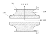
상기 인너파이프(3)는 길이방향을 따라 일측에 소외경부(13)가 구비되고, 타측에 상기 소외경부(13)보다 외곽 직경이 큰 대외경부(15)가 구비되며, 상기 소외경부(13)와 대외경부(15) 사이는 부드러운 경사면으로 연결된다.
The inner pipe (3) is provided with an outer diameter portion (13) on one side along the longitudinal direction, the outer diameter portion (15) having a larger outer diameter than the outer diameter portion (13) on the other side, the outer diameter portion (13) And the
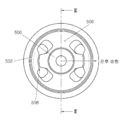
본 실시예에서, 상기 소외경부(13)는 상기 중공부(1)와 동심축을 이루는 원주형으로 형성되고, 상기 대외경부(15)는 상기 중공부(1)의 원주방향을 따라 다수의 돌출부(9)가 배치되어 굴곡을 이루는 형상으로 형성되며, 상기 다수의 돌출부(9)가 상기 중공부(1)로부터 돌출된 반경방향 길이는 원주방향을 따라 차례로 교번하여 변화하도록 형성된다.
In the present embodiment, the
본 실시예에서는 상기 돌출부(9)는 4개가 구비되어 도 7에서 확인할 수 있듯이 수직방향의 두 개는 수평방향의 두 개에 비하여 상대적으로 반경방향으로 돌출된 길이가 길게 형성되어 있다.
In the present embodiment, four
상기 아웃터파이프(5)는 일측에 상기 인너파이프(3)의 소외경부(13)가 관통되도록 소내경부(11)가 형성되고, 타측에 상기 인너파이프(3)의 대외경부(15)를 감싸도록 대내경부(17)가 형성되며, 상기 소내경부(11)와 대내경부(17) 사이는 상기 인너파이프(3)의 경사면에 상응하는 형상의 경사면으로 연결된다.
The
상기 아웃터파이프(5)의 대내경부(17)의 단부에는 반경방향 외측으로 벌어지는 형상의 플랜지(19)가 구비되고, 상기 완충부재(7)는 상기 플랜지(19)의 일측면까지 연장되어 형성되는 바, 도 7에는 상기 연장되어 형성된 완충부재(7)가 원형으로 표현되어 있다.
The end portion of the
상기 완충부재(7)에는 상기 인너파이프(3)의 돌출부(9)들 사이의 공간에 상기 인너파이프(3)와 아웃터파이프(5)를 연결하는 브릿지(21)가 형성되고, 상기 인너파이프(3)의 돌출부(9)가 돌출된 부위에서 상기 플랜지(19)쪽으로부터 함몰된 공간으로 갭(23)이 형성되며, 상기 인너파이프(3)와 아웃터파이프(5)의 경사면들 사이에는 공간 없이 채워진 스토퍼부(25)가 형성된다.
The
즉, 상기 스토퍼부(25)는 상기 인너파이프(3)와 아웃터파이프(5)가 상기 중공부(1)의 축방향으로 상대적으로 이동하려고 할 때, 상기 완충부재(7)의 스토퍼부(25)가 압축되면서 견실한 강성을 제공할 수 있도록 한 것이다.
That is, the
물론, 상기 완충부재(7)에 형성되는 상기 갭(23)은 상기 트레일링암 부시의 반경방향 강성 및 변형량, 즉, 차량의 전후방향 및 상하방향의 강성 및 변형량을 적절히 확보할 수 있도록 형성됨으로써, 상기한 바와 같은 구성의 트레일링암 부시는 차량의 전후방향, 상하방향은 물론, 차량의 횡방향을 따른 강성값을 서로 독립적으로 튜닝할 수 있어서, 차량에서 원하는 핸들링 성능과 승차감 및 로드노이즈 특성을 고루 충족시킬 수 있도록 한다.Of course, the
1; 중공부
3; 인너파이프
5; 아웃터파이프
7; 완충부재
9; 돌출부
11; 소내경부
13; 소외경부
15; 대외경부
17; 대내경부
19; 플랜지
21; 브릿지
23; 갭
25; 스토퍼부One; Hollow portion
3; Inner pipe
5; Outer pipe
7; Buffer member
9; projection part
11; Small neck
13; Marginalized neck
15; External cervix
17; Internal neck
19; flange
21; bridge
23; gap
25; Stopper part
Claims (6)
상기 인너파이프의 외측에 위치하며, 상기 인너파이프의 변화하는 외곽형상에 상응하도록 단면형상이 변화하도록 형성되어, 상기 중공부의 축방향을 따른 투영면의 일부가 상기 인너파이프의 투영면 일부와 중첩되도록 형성된 아웃터파이프와;
상기 중첩되는 투영면들을 형성하게 되는 상기 인너파이프와 아웃터파이프의 부분들 사이를 포함하여 상기 인너파이프와 아웃터파이프 사이에 개재된 완충부재;
를 포함하여 구성된 차량의 트레일링암 부시.An inner pipe having a hollow portion linearly penetrated at the center thereof and configured to change an outer shape of a cross section along an axial direction of the hollow portion;
Located outside the inner pipe and formed so that the cross-sectional shape is changed to correspond to the changing outer shape of the inner pipe, the outer portion formed so that a portion of the projection surface along the axial direction of the hollow portion overlaps with a portion of the projection surface of the inner pipe With pipes;
A cushioning member interposed between the inner pipe and the outer pipe including portions of the inner pipe and the outer pipe forming the overlapping projection surfaces;
The trailing arm bush of the vehicle, including.
상기 인너파이프는 길이방향을 따라 일측에 소외경부가 구비되고, 타측에 상기 소외경부보다 외곽 직경이 큰 대외경부가 구비되며, 상기 소외경부와 대외경부 사이는 부드러운 경사면으로 연결된 것
을 특징으로 하는 차량의 트레일링암 부시. The method according to claim 1,
The inner pipe is provided with a marginal diameter portion on one side along the longitudinal direction, the outer diameter portion having a larger outer diameter than the marginal diameter portion on the other side, it is connected between the marginal diameter portion and the outer diameter portion by a smooth inclined surface
The trailing arm bush of the vehicle.
상기 소외경부는 상기 중공부와 동심축을 이루는 원주형으로 형성되고;
상기 대외경부는 상기 중공부의 원주방향을 따라 다수의 돌출부가 배치되어 굴곡을 이루는 형상으로 형성되며, 상기 다수의 돌출부가 상기 중공부로부터 돌출된 반경방향 길이는 원주방향을 따라 차례로 교번하여 변화하도록 형성된 것
을 특징으로 하는 차량의 트레일링암 부시.The method according to claim 2,
The marginal diameter portion is formed in a columnar shape concentric with the hollow portion;
The outer diameter portion is formed in a shape in which a plurality of protrusions are arranged along the circumferential direction of the hollow portion to form a bend, the radial length of the plurality of protrusions protruding from the hollow portion is formed to alternately change along the circumferential direction in order that
The trailing arm bush of the vehicle.
상기 아웃터파이프는
일측에 상기 인너파이프의 소외경부가 관통되도록 소내경부가 형성되고;
타측에 상기 인너파이프의 대외경부를 감싸도록 대내경부가 형성되며;
상기 소내경부와 대내경부 사이는 상기 인너파이프의 경사면에 상응하는 형상의 경사면으로 연결된 것
을 특징으로 하는 차량의 트레일링암 부시.The method according to claim 3,
The outer pipe is
A small inner diameter portion is formed at one side such that the outer diameter portion of the inner pipe penetrates;
An inner diameter portion is formed on the other side to surround the outer diameter portion of the inner pipe;
Between the small diameter portion and the large diameter portion is connected to the inclined surface of the shape corresponding to the inclined surface of the inner pipe
The trailing arm bush of the vehicle.
상기 아웃터파이프의 대내경부의 단부에는 반경방향 외측으로 벌어지는 형상의 플랜지가 구비되고;
상기 완충부재는 상기 플랜지의 일측면까지 연장되어 형성된 것
을 특징으로 하는 차량의 트레일링암 부시.The method of claim 4,
An end portion of the outer diameter portion of the outer pipe is provided with a flange that is radially outwardly shaped;
The buffer member is formed to extend to one side of the flange
The trailing arm bush of the vehicle.
상기 완충부재에는
상기 인너파이프의 돌출부들 사이의 공간에 상기 인너파이프와 아웃터파이프를 연결하는 브릿지가 형성되고;
상기 인너파이프의 돌출부가 돌출된 부위에서 상기 플랜지쪽으로부터 함몰된 공간으로 갭이 형성되며;
상기 인너파이프와 아웃터파이프의 경사면들 사이에는 공간 없이 채워진 스토퍼부가 형성된 것
을 특징으로 하는 차량의 트레일링암 부시.The method according to claim 5,
The buffer member
A bridge connecting the inner pipe and the outer pipe is formed in a space between the protrusions of the inner pipe;
A gap is formed from a protruding portion of the inner pipe to a space recessed from the flange side;
Between the inclined surfaces of the inner pipe and the outer pipe is formed a stopper portion filled without space
The trailing arm bush of the vehicle.
Priority Applications (1)
| Application Number | Priority Date | Filing Date | Title |
|---|---|---|---|
| KR1020110014945A KR20120095557A (en) | 2011-02-21 | 2011-02-21 | Trailing arm bush for vehicle |
Applications Claiming Priority (1)
| Application Number | Priority Date | Filing Date | Title |
|---|---|---|---|
| KR1020110014945A KR20120095557A (en) | 2011-02-21 | 2011-02-21 | Trailing arm bush for vehicle |
Publications (1)
| Publication Number | Publication Date |
|---|---|
| KR20120095557A true KR20120095557A (en) | 2012-08-29 |
Family
ID=46885970
Family Applications (1)
| Application Number | Title | Priority Date | Filing Date |
|---|---|---|---|
| KR1020110014945A KR20120095557A (en) | 2011-02-21 | 2011-02-21 | Trailing arm bush for vehicle |
Country Status (1)
| Country | Link |
|---|---|
| KR (1) | KR20120095557A (en) |
Cited By (3)
| Publication number | Priority date | Publication date | Assignee | Title |
|---|---|---|---|---|
| CN104527354A (en) * | 2015-01-26 | 2015-04-22 | 安徽江淮汽车股份有限公司 | Swing arm bushing structure and automobile |
| KR102033154B1 (en) * | 2018-04-30 | 2019-11-29 | 평화산업주식회사 | Suspension bush structure of electric vehicle |
| CN115217875A (en) * | 2022-07-29 | 2022-10-21 | 重庆长安汽车股份有限公司 | Front swing arm rear bushing and front swing arm |
-
2011
- 2011-02-21 KR KR1020110014945A patent/KR20120095557A/en not_active Application Discontinuation
Cited By (3)
| Publication number | Priority date | Publication date | Assignee | Title |
|---|---|---|---|---|
| CN104527354A (en) * | 2015-01-26 | 2015-04-22 | 安徽江淮汽车股份有限公司 | Swing arm bushing structure and automobile |
| KR102033154B1 (en) * | 2018-04-30 | 2019-11-29 | 평화산업주식회사 | Suspension bush structure of electric vehicle |
| CN115217875A (en) * | 2022-07-29 | 2022-10-21 | 重庆长安汽车股份有限公司 | Front swing arm rear bushing and front swing arm |
Similar Documents
| Publication | Publication Date | Title |
|---|---|---|
| US9579946B2 (en) | Trailing arm bush for coupled torsion beam axle | |
| JP2015020670A (en) | Trailing arm | |
| KR20120095557A (en) | Trailing arm bush for vehicle | |
| CN206106852U (en) | Swing arm bush and swing arm liner assembly | |
| CN105074261B (en) | Antihunting device | |
| CN207018410U (en) | Buffer stopper, damping device and vehicle for chassis damping | |
| JP5568522B2 (en) | Damper mount | |
| KR20150118668A (en) | Trailing arm bush | |
| CN102829113A (en) | Drum-type shock absorption suspension device | |
| JP2014190509A (en) | Vibration control device | |
| CN204200937U (en) | One rises type automobile shock inner sleeve | |
| CN104290555B (en) | A kind of automotive suspension bloom-base | |
| US20170341662A1 (en) | Wheelset Guide For A Vehicle | |
| CN203739567U (en) | Car multi-connecting-rod suspension longitudinal support arm bush | |
| CN104132088A (en) | Shock pad for vehicle | |
| CN202646495U (en) | Auxiliary vehicle frame bushing block | |
| CN204415120U (en) | A kind of power assembly hydraulic suspension of automobile | |
| CN202753755U (en) | Automobile power assembly rubber suspension cushion | |
| KR101321033B1 (en) | Structure of rear subflame mounted on stabilizer bar | |
| KR20130052959A (en) | Arm bush mounting structure for suspension | |
| CN203202112U (en) | Shock-absorber connection supporting device | |
| CN206186716U (en) | Which comprises a body, | |
| CN207809048U (en) | A kind of lifting lug of automobile exhaust pipe | |
| KR20110060562A (en) | Lower arm bush unit for vehicle | |
| KR102614124B1 (en) | Shock absorber having spring seat of suspension for vehicle |
Legal Events
| Date | Code | Title | Description |
|---|---|---|---|
| A201 | Request for examination | ||
| E902 | Notification of reason for refusal | ||
| E601 | Decision to refuse application |