KR20120073312A - Machine displacement adjustment system for machine tools - Google Patents
Machine displacement adjustment system for machine tools Download PDFInfo
- Publication number
- KR20120073312A KR20120073312A KR1020127011071A KR20127011071A KR20120073312A KR 20120073312 A KR20120073312 A KR 20120073312A KR 1020127011071 A KR1020127011071 A KR 1020127011071A KR 20127011071 A KR20127011071 A KR 20127011071A KR 20120073312 A KR20120073312 A KR 20120073312A
- Authority
- KR
- South Korea
- Prior art keywords
- amount
- displacement
- axis
- correction
- inclination
- Prior art date
Links
Images


Classifications
-
- B—PERFORMING OPERATIONS; TRANSPORTING
- B23—MACHINE TOOLS; METAL-WORKING NOT OTHERWISE PROVIDED FOR
- B23Q—DETAILS, COMPONENTS, OR ACCESSORIES FOR MACHINE TOOLS, e.g. ARRANGEMENTS FOR COPYING OR CONTROLLING; MACHINE TOOLS IN GENERAL CHARACTERISED BY THE CONSTRUCTION OF PARTICULAR DETAILS OR COMPONENTS; COMBINATIONS OR ASSOCIATIONS OF METAL-WORKING MACHINES, NOT DIRECTED TO A PARTICULAR RESULT
- B23Q17/00—Arrangements for observing, indicating or measuring on machine tools
-
- B—PERFORMING OPERATIONS; TRANSPORTING
- B23—MACHINE TOOLS; METAL-WORKING NOT OTHERWISE PROVIDED FOR
- B23Q—DETAILS, COMPONENTS, OR ACCESSORIES FOR MACHINE TOOLS, e.g. ARRANGEMENTS FOR COPYING OR CONTROLLING; MACHINE TOOLS IN GENERAL CHARACTERISED BY THE CONSTRUCTION OF PARTICULAR DETAILS OR COMPONENTS; COMBINATIONS OR ASSOCIATIONS OF METAL-WORKING MACHINES, NOT DIRECTED TO A PARTICULAR RESULT
- B23Q11/00—Accessories fitted to machine tools for keeping tools or parts of the machine in good working condition or for cooling work; Safety devices specially combined with or arranged in, or specially adapted for use in connection with, machine tools
- B23Q11/001—Arrangements compensating weight or flexion on parts of the machine
- B23Q11/0028—Arrangements compensating weight or flexion on parts of the machine by actively reacting to a change of the configuration of the machine
-
- B—PERFORMING OPERATIONS; TRANSPORTING
- B23—MACHINE TOOLS; METAL-WORKING NOT OTHERWISE PROVIDED FOR
- B23Q—DETAILS, COMPONENTS, OR ACCESSORIES FOR MACHINE TOOLS, e.g. ARRANGEMENTS FOR COPYING OR CONTROLLING; MACHINE TOOLS IN GENERAL CHARACTERISED BY THE CONSTRUCTION OF PARTICULAR DETAILS OR COMPONENTS; COMBINATIONS OR ASSOCIATIONS OF METAL-WORKING MACHINES, NOT DIRECTED TO A PARTICULAR RESULT
- B23Q15/00—Automatic control or regulation of feed movement, cutting velocity or position of tool or work
- B23Q15/007—Automatic control or regulation of feed movement, cutting velocity or position of tool or work while the tool acts upon the workpiece
- B23Q15/18—Compensation of tool-deflection due to temperature or force
-
- B—PERFORMING OPERATIONS; TRANSPORTING
- B23—MACHINE TOOLS; METAL-WORKING NOT OTHERWISE PROVIDED FOR
- B23Q—DETAILS, COMPONENTS, OR ACCESSORIES FOR MACHINE TOOLS, e.g. ARRANGEMENTS FOR COPYING OR CONTROLLING; MACHINE TOOLS IN GENERAL CHARACTERISED BY THE CONSTRUCTION OF PARTICULAR DETAILS OR COMPONENTS; COMBINATIONS OR ASSOCIATIONS OF METAL-WORKING MACHINES, NOT DIRECTED TO A PARTICULAR RESULT
- B23Q17/00—Arrangements for observing, indicating or measuring on machine tools
- B23Q17/22—Arrangements for observing, indicating or measuring on machine tools for indicating or measuring existing or desired position of tool or work
-
- G—PHYSICS
- G05—CONTROLLING; REGULATING
- G05B—CONTROL OR REGULATING SYSTEMS IN GENERAL; FUNCTIONAL ELEMENTS OF SUCH SYSTEMS; MONITORING OR TESTING ARRANGEMENTS FOR SUCH SYSTEMS OR ELEMENTS
- G05B19/00—Programme-control systems
- G05B19/02—Programme-control systems electric
- G05B19/18—Numerical control [NC], i.e. automatically operating machines, in particular machine tools, e.g. in a manufacturing environment, so as to execute positioning, movement or co-ordinated operations by means of programme data in numerical form
- G05B19/404—Numerical control [NC], i.e. automatically operating machines, in particular machine tools, e.g. in a manufacturing environment, so as to execute positioning, movement or co-ordinated operations by means of programme data in numerical form characterised by control arrangements for compensation, e.g. for backlash, overshoot, tool offset, tool wear, temperature, machine construction errors, load, inertia
-
- G—PHYSICS
- G05—CONTROLLING; REGULATING
- G05B—CONTROL OR REGULATING SYSTEMS IN GENERAL; FUNCTIONAL ELEMENTS OF SUCH SYSTEMS; MONITORING OR TESTING ARRANGEMENTS FOR SUCH SYSTEMS OR ELEMENTS
- G05B2219/00—Program-control systems
- G05B2219/30—Nc systems
- G05B2219/50—Machine tool, machine tool null till machine tool work handling
- G05B2219/50046—Control of level, horizontal, inclination of workholder, slide
Abstract
본 발명은 칼럼 등의 기계 구조물의 경사 각도를 직접 검출할 수 있는 수준기 등의 경사 각도 검출기를 이용한 공작 기계의 기계 변위 보정 시스템을 제공하는 것을 목적으로 한다. 이를 위해, 공작 기계의 구조물에 배치되고, 상기 구조물의 경사 각도를 검출하여 경사량 데이터를 출력하는 경사 각도 검출기(수준기)와, 상기 경사 각도 검출기로부터 상기 경사량을 데이터(c1 내지 c6)에 근거하여 상기 구조물의 기계 변위량을 산출하는 기계 변위량 산출부(94)와, 상기 기계 변위량 산출부에서 산출한 상기 구조물의 기계 변위량에 근거하여 상기 공작 기계의 이둥축(X축, Y축, Z축)의 보정량을 산출하는 보정량 산출부(95)를 갖는 보정 장치(92)를 구비한 구성으로 한다.An object of the present invention is to provide a machine displacement correction system of a machine tool using an inclination angle detector such as a level that can directly detect an inclination angle of a machine structure such as a column. To this end, an inclination angle detector (level) that is disposed on a structure of a machine tool and detects an inclination angle of the structure and outputs inclination amount data, and the inclination amount from the inclination angle detector are based on data c1 to c6. A mechanical displacement amount calculation unit 94 for calculating a mechanical displacement amount of the structure and a moving axis (X, Y, Z axis) of the machine tool based on the mechanical displacement amount of the structure calculated by the mechanical displacement amount calculation unit. It is set as the structure provided with the correction apparatus 92 which has the correction amount calculation part 95 which calculates the correction amount of this.

Description
본 발명은 공작 기계의 기계 변위(열 변위, 자중 변위, 레벨 변위)를 보정하기 위한 기계 변위 보정 시스템에 관한 것이다. The present invention relates to a machine displacement correction system for correcting a machine displacement (thermal displacement, self-weight displacement, level displacement) of a machine tool.
일반적으로 공작 기계의 위치 결정 제어를 실행하는 서보 제어 장치에는, 도 7에 도시하는 바와 같은 완전 폐쇄 루프의 피드백 제어계가 채용되어 있다. 구체적인 설명은 생략하지만, 도 7에 도시하는 서보 제어 장치에서는, 이동체(1)에 마련된 위치 검출기(2)로부터의 위치 피드백 정보(즉 기계 단부의 위치 정보)와, 서보 모터(3)에 마련된 펄스 코더(4)로부터 미분 연산부(5)를 거쳐서 피드백되는 속도 피드백 정보에 근거하여, 서보 모터(3)의 회전을 제어하는 것에 의해, 이동체(1)의 위치가 위치 지령에 추종하도록 위치 결정 제어를 실행한다. 또한, 도 7에 있어서, Kp는 위치 루프 게인, Kv는 속도 루프 비례 게인, Kvi는 속도 루프 적분 게인, s는 라플라스 연산자이다. Generally, the fully closed loop feedback control system as shown in FIG. 7 is employ | adopted as the servo control apparatus which performs positioning control of a machine tool. Although the detailed description is omitted, in the servo control device shown in FIG. 7, the position feedback information (that is, the position information at the end of the machine) from the
상기와 같이 완전 폐쇄 루프의 피드백 제어계에서는 기계 단부의 위치 정보를 위치 피드백 정보로서 사용하고 있지만, 공작 기계내에 갖는 주축이나 서보 모터(3) 등의 열원이나 외기의 온도 변화에 의해서 공작 기계의 각 구조물에 기계 변위가 발생하면, 공작 기계의 각 이동축의 위치 결정 정밀도나 3차원 공간에 있어서의 공구의 위치 결정 정밀도 등의 정적 정밀도는 악화된다. 기계 변위는 단순히 열 변위에 의한 것 뿐만이 아니고, 자중에 의한 휨이나 레벨 변위에 의한 구조물의 휨 등에 의해서도 발생한다. As described above, in the feedback control system of the fully closed loop, the position information of the end of the machine is used as position feedback information. When a mechanical displacement occurs, static accuracy such as positioning accuracy of each moving shaft of the machine tool or positioning accuracy of the tool in three-dimensional space is deteriorated. Mechanical displacement is not only caused by thermal displacement, but also caused by warpage due to its own weight, structure warpage due to level displacement, and the like.
또한, 공작 기계의 제어계로서 도 8에 도시하는 반폐쇄 루프의 피드백 제어계를 채용했을 경우에는, 위치 피드백 정보로서 서보 모터(3)의 위치 정보[펄스 코더(4)로 검출하는 서보 모터(3)의 회전 각도]를 사용하고 있기 때문에, 더욱 정적 정도는 악화되는 경향이 된다. 또한, 이와 같은 기계 변위는 로봇 등의 제어에 있어서도 마찬가지로 발생한다. In addition, when the feedback control system of the semi-closed loop shown in FIG. 8 is employ | adopted as a control system of a machine tool, the positional information of the servo motor 3 (the
이들 기계 변위에 의한 정적 정밀도의 악화, 특히 열 등에 기인하여 발생하는 기계 변위에 의한 정적 정밀도 악화는, 가공 오차 증대의 큰 요인 중 하나이며, 현재에도 또한 큰 문제이다. 그들 정적 정밀도 악화의 대책으로서는, 종래부터, 온도 센서를 기계에 매립하고, 그 온도 데이터를 기초로 기계의 열 변위량을 간이적인 산술식을 이용하고 추측하여, 그 변위량분 만큼 기계 좌표 등을 시프트 시키는 것에 의해서 기계 변위량을 보상하는 열 변위 보정 시스템을 공작 기계의 제어계에 마련하는 것이 알려져 있다. 이 열 변위 보정 시스템의 구체적인 예를 도 9 및 도 10에 도시한다. Deterioration of static accuracy due to these mechanical displacements, in particular, deterioration of static accuracy due to mechanical displacement caused by heat or the like, is one of the major factors for increasing the machining error, and is still a big problem even now. As a countermeasure against such static precision deterioration, conventionally, a temperature sensor is embedded in a machine, and the machine's thermal displacement amount is estimated by using a simple arithmetic formula based on the temperature data, and the machine coordinates are shifted by the displacement amount. It is known to provide a control system of a machine tool with a thermal displacement correction system that compensates for the amount of mechanical displacement. 9 and 10 show specific examples of this thermal displacement correction system.
도 9는 횡형상 머시닝 센터의 경우이며, 온도 센서(23-1 내지 23-10)가, 베드(11)와, 칼럼(12)과, X축방향으로 이동 가능한 새들(13)과, 주축(25)이 마련되며 Z축방향으로 이동 가능한 헤드(14)와, Y축방향으로 이동 가능한 테이블(15)과, 테이블(15)상에 탑재된 워크(W)의 각각에 배설되어 있다. 이들의 온도 센서(23-1 내지 23-10)에서는, 각 구조물[베드(11), 칼럼(12), 새들(13), 헤드(14), 테이블(15)] 및 워크(W)의 온도를 검출하여, 온도 데이터(온도 검출 신호)(a1 내지 a10)를 출력한다. 9 shows a case of a horizontal machining center, in which the temperature sensors 23-1 to 23-10 include a bed 11, a
보정 장치(24)는, 온도 데이터 입력부(16)와 열 변위량 산출부(17)와 보정량 산출부(18)를 갖고 있다. 온도 데이터 입력부(16)에서는, 온도 센서(23-1 내지 23-10)로부터 온도 데이터(a1 내지 a10)를 입력한다. 열 변위량 산출부(17)에서는, 온도 데이터 입력부(16)에서 입력한 온도 데이터(a1 내지 a10)에 근거하여, 열에 의한 각 구조물[베드(11), 칼럼(12), 새들(13), 헤드(14), 테이블(15)]이나 워크(W)의 변위량을 산출한다. 보정량 산출부(18)에서는, 열 변위량 산출부(17)에서 산출한 각 구조물[베드(11), 칼럼(12), 새들(13), 헤드(14), 테이블(15)]이나 워크(W)의 열 변위량에 근거하여, 각 이동축(X축, Y축, Z축)에 있어서의 변위량을 산출하고, 이들의 변위량의 역 부호의 값을 각 이동축(X축, Y축, Z축)의 보정량으로 하고, 이들의 보정량을 각 이동축(X축, Y축, Z축)의 서보 제어 장치(19, 20, 21)에 송출한다.The
X축의 서보 제어 장치(19)에서는, 편차 연산부(22)에 있어서, 보정량 산출부(18)에서 산출한 X축의 보정량(="-X축의 변위량")을 X축 위치 지령에 가산하는 것에 의해 X축의 위치 지령을 보정하고, 이 보정 후의 X축의 위치 지령과 X축의 위치 피드백 정보의 편차를 연산한다. Y축의 서보 제어 장치(20)에서는, 편차 연산부(22)에 있어서, 보정량 산출부(18)에서 산출한 Y축의 보정량(="-Y축의 변위량")을 Y축의 위치 지령에 가산하는 것에 의해 Y축의 위치 지령을 보정하고, 이 보정 후의 Y축의 위치 지령과 Y축의 위치 피드백 정보의 편차를 연산한다. Z축의 서보 제어 장치(21)에서는, 편차 연산부(22)에 있어서, 보정량 산출부(18)에서 산출한 Z축의 보정량(="-Z축의 변위량")을 Z축의 위치 지령에 가산하는 것에 의해 Z축의 위치 지령을 보정하고, 이 보정 후의 Z축의 위치 지령과 Z축의 위치 피드백 정보의 편차를 연산한다. In the X-axis
도 10은 문형상 머시닝 센터의 경우이며, 온도 센서(45-1 내지 45-8)가, 베드(31)와 문형상의 칼럼(32)과, 주축(36)이 내장되어 있는 램(35)과, 테이블(37)과, 테이블(37)에 탑재된 워크(W)에 각각 배설되어 있다. 이들의 온도 센서(45-1 내지 45-8)에서는, 각 구조물[베드(31), 칼럼(32), 램(35), 테이블(37)] 및 워크(W)의 온도를 검출하여, 온도 데이터(온도 검출 신호)(b1 내지 b8)를 출력한다. 또한, 테이블(37)은 X축방향으로 이동 가능하고, 새들(34)은 크로스 레일(33)을 따라서 Y축방향으로 이동 가능하며, 램(35)[주축(36)]은 Z축방향으로 이동 가능하다.10 shows a case of a door-shaped machining center, in which the temperature sensors 45-1 to 45-8 include a
보정 장치(46)는, 온도 데이터 입력부(38)와 열 변위량 산출부(39)와 보정량 산출부(40)를 갖고 있다. 온도 데이터 입력부(38)에서는, 온도 센서(45-1 내지 45-8)로부터 온도 데이터(b1 내지 b8)를 입력한다. 열 변위량 산출부(39)에서는, 온도 데이터 입력부(38)에서 입력한 온도 데이터(b1 내지 b8)에 근거하여, 열에 의한 각 구조물[베드(31), 칼럼(32), 램(35), 테이블(37)] 및 워크(W)의 변위량을 산출한다. 보정량 산출부(40)에서는, 열 변위량 산출부(39)에서 산출한 각 구조물[베드(31), 칼럼(32), 램(35), 테이블(37)]이나 워크(W)의 열 변위량에 근거하여, 각 이동축(X축, Y축, Z축)에 있어서의 변위량을 산출하고, 이들의 변위량의 역 부호의 값을 각 이동축(X축, Y축, Z축)의 보정량으로 하고, 이들의 보정량을 각 이동축(X축, Y축, Z축)의 서보 제어 장치(41, 42, 43)로 송출한다. The
X축의 서보 제어 장치(41)에서는, 편차 연산부(44)에 대하여, 보정량 산출부(40)에서 산출한 X축의 보정량(="-X축의 변위량")을 X축의 위치 지령에 가산하는 것에 의해 X축의 위치 지령을 보정하고, 이 보정 후의 X축의 위치 지령과 X축의 위치 피드백 정보의 편차를 연산한다. Y축의 서보 제어 장치(42)에서는, 편차 연산부(44)에 있어서, 보정량 산출부(40)에서 산출한 Y축의 보정량(="-Y축의 변위량")을 Y축의 위치 지령에 가산하는 것에 의해 Y축의 위치 지령을 보정하고, 이 보정 후의 Y축의 위치 지령과 Y축의 위치 피드백 정보의 편차를 연산한다. Z축의 서보 제어 장치(43)에서는, 편차 연산부(44)에 대하여, 보정량 산출부(40)에서 산출한 Z축의 보정량(="-Z축의 변위량")을 Z축의 위치 지령에 가산하는 것에 의해 Z축의 위치 지령을 보정하고, 이 보정 후의 Z축의 위치 지령과 Z축의 위치 피드백 정보의 편차를 연산한다. In the
이와 같은 온도 센서를 이용한 열 변위 보정 시스템에 관련하는 선행 기술 문헌으로서는, 하기의 특허 문헌 1 내지 5가 있다. As a prior art document related to a thermal displacement correction system using such a temperature sensor,
그렇지만, 기계의 열 변위량의 추측에 사용하는 온도 센서의 개수는 무제한이 아니기 때문에, 기계의 열 변위량을 완전하게 파악하는 것은 곤란하다. 또한, 종래의 방법에서는 온도 센서의 검출값으로부터 기계의 열 변위 모드 및 열 변위량을 추정하여 구하고 있기 때문에, 열 변위를 완전하게 보상할 수 없다. However, since the number of temperature sensors used for estimating the thermal displacement amount of the machine is not unlimited, it is difficult to completely grasp the thermal displacement amount of the machine. In the conventional method, since the thermal displacement mode and the thermal displacement amount of the machine are estimated and obtained from the detected value of the temperature sensor, the thermal displacement cannot be completely compensated.
또한, 한쪽에서 기계의 열 변위를 극히 순수한 열 변위 모드로 하는 것을 목적으로 하여, 상기 특허 문헌 6에 기재된 발명 등이 제안되고 있다. 그렇지만, 외기 온도의 변화 등에 의한 기계의 열 변위를 완전히 순수한 열 변위 모드로 하는 것(칼럼 등의 휨, 쓰러짐 등을 배제하고, 신축 모드로만 하는 것)은 곤란하며, 외기 온도의 변화 등에 의한 칼럼 등의 휨 상태나, 쓰러짐을 완전하게 배제하는 것은 곤란하다. Moreover, the invention etc. which were described in the said patent document 6 are proposed in order to make thermal displacement of a machine into the ultra pure thermal displacement mode on one side. However, it is difficult to completely set the thermal displacement of the machine due to a change in the outside air temperature to a purely pure thermal displacement mode (except to warp, collapse, etc. of the column and to the stretch mode only), and the column due to the change of the ambient temperature is difficult. It is difficult to completely exclude the warpage state and collapse of the back.
따라서 본 발명은 상기의 사정에 감안하여, 칼럼 등의 기계 구조물의 경사 각도를 직접 검출할 수 있는 수준기 등의 경사 각도 검출기를 이용한 공작 기계의 기계 변위 보정 시스템을 제공하는 것을 과제로 한다. Accordingly, in view of the above circumstances, it is an object of the present invention to provide a machine displacement correction system for a machine tool using an inclination angle detector such as a level that can directly detect the inclination angle of a machine structure such as a column.
또한, 상기 특허 문헌(7)에서는 수준기를 사용한 발명이 제안되어 있지만, 이 발명은 수준기와 압전 액추에이터를 조합한 자세 제어 장치에 관한 것이고, 기계 변위를 보정하는 시스템이 아니며, 본 발명의 목적과는 다르다. In addition, although the invention using a leveler is proposed in the said patent document (7), this invention relates to the attitude control apparatus which combined the leveler and the piezoelectric actuator, and is not a system which correct | amends a mechanical displacement, and with the objective of this invention different.
상기 과제를 해결하는 제 1 발명의 공작 기계의 기계 변위 보정 시스템은, 공작 기계의 기계 변위를 보정하는 기계 변위 보정 시스템으로서, The machine displacement correction system of the machine tool of the 1st invention which solves the said subject is a machine displacement correction system which corrects the machine displacement of a machine tool,
상기 공작 기계의 구조물에 배치되고, 상기 구조물의 경사 각도를 검출하여 경사량 데이터를 출력하는 경사 각도 검출기와, An inclination angle detector disposed on a structure of the machine tool and detecting an inclination angle of the structure and outputting inclination amount data;
상기 경사 각도 검출기로부터 상기 경사량 데이터를 입력하는 경사량 데이터 입력부와, 상기 경사량 데이터 입력부에서 입력한 상기 경사량 데이터에 근거하여 상기 구조물의 기계 변위량을 산출하는 기계 변위량 산출부와, 상기 기계 변위량 산출부에서 산출한 상기 구조물의 기계 변위량에 근거하여 상기 공작 기계의 이동축의 보정량을 산출하는 보정량 산출부를 갖는 보정 장치를 구비한 것을 특징으로 한다.An inclination amount data input unit for inputting the inclination amount data from the inclination angle detector, a mechanical displacement amount calculating unit for calculating a mechanical displacement amount of the structure based on the inclination amount data input by the inclination amount data input unit, and the mechanical displacement amount And a correction device having a correction amount calculation unit that calculates a correction amount of the moving shaft of the machine tool based on the mechanical displacement amount of the structure calculated by the calculation unit.
또한, 제 2 발명의 공작 기계의 기계 변위 보정 시스템은, 공작 기계의 기계 변위를 보정하는 기계 변위 보정 시스템으로서, Moreover, the machine displacement correction system of the machine tool of 2nd invention is a machine displacement correction system which corrects the machine displacement of a machine tool,
상기 공작 기계의 구조물에 설치되고, 상기 구조물의 경사 각도를 검출하여 경사량 데이터를 출력하는 경사 각도 검출기와An inclination angle detector installed in the structure of the machine tool and detecting an inclination angle of the structure and outputting inclination amount data;
상기 공작 기계의 구조물 또는 워크에 설치되고, 상기 구조물 또는 상기 워크의 온도를 검출하여 온도 데이터를 출력하는 온도 센서와, A temperature sensor installed in a structure or a work of the machine tool and detecting temperature of the structure or the work and outputting temperature data;
상기 경사 각도 검출기로부터 상기 경사량 데이터를 입력하는 경사량 데이터 입력부와, 상기 경사량 데이터 입력부에서 입력한 상기 경사량 데이터에 근거하여 상기 구조물의 기계 변위량을 산출하는 기계 변위량 산출부와, 상기 기계 변위량 산출부에서 산출한 상기 구조물의 기계 변위량에 근거하여 상기 공작 기계의 이동축의 제 1 보정량을 산출하는 제 1 보정량 산출부와, 상기 온도 센서로부터 상기 온도 데이터를 입력하는 온도 데이터 입력부와, 상기 온도 데이터 입력부에서 입력한 상기 온도 데이터에 근거하여 상기 구조물 또는 상기 워크의 열 변위량을 산출하는 열 변위량 산출부와, 상기 열 변위량 산출부에서 산출한 상기 구조물 또는 상기 워크의 열 변위량에 근거하여 상기 이동축의 제 2 보정량을 산출하는 제 2 보정량 산출부와, 상기 제 1 보정량 산출부에서 산출한 상기 제 1 보정량과 상기 제 2 보정량 산출부에서 산출한 상기 제 2 보정량을 가산하는 보정량 가산부를 갖는 보정 장치를 구비한 것을 특징으로 한다. An inclination amount data input unit for inputting the inclination amount data from the inclination angle detector, a mechanical displacement amount calculating unit for calculating a mechanical displacement amount of the structure based on the inclination amount data input by the inclination amount data input unit, and the mechanical displacement amount A first correction amount calculation unit that calculates a first correction amount of the moving shaft of the machine tool based on the mechanical displacement amount of the structure calculated by the calculation unit, a temperature data input unit which inputs the temperature data from the temperature sensor, and the temperature data A heat displacement calculation unit configured to calculate a heat displacement amount of the structure or the workpiece based on the temperature data inputted from an input unit, and a displacement of the moving shaft based on the heat displacement amount of the structure or the workpiece calculated by the heat displacement calculation unit. A second correction amount calculating unit for calculating a second correction amount; And a correction amount adding unit for adding the first correction amount calculated by the first correction amount calculating unit and the second correction amount calculated by the second correction amount calculating unit.
제 1 발명의 공작 기계의 기계 변위 보정 시스템에 의하면, 휨, 쓰러짐 등의 기계 변위(열 변위, 자중 변위 또는 레벨 변위, 혹은, 열 변위, 자중 변위, 레벨 변위의 혼성)에 의해서 공작 기계의 구조물이 경사졌을 때, 이 구조물의 경사량(경사 각도)을 직접, 경사 각도 검출기(예를 들면 수준기)에 의해서 파악할 수 있다. 이 때문에, 이 경사 각도 검출기에서 직접 파악한 구조물의 경사량 데이터에 근거하여 구조물의 기계 변위량을 산출하는 것에 의해, 해당 기계 변위량을 정밀도 양호하게 추정할 수 있어, 해당 기계 변위량에 근거하여 정밀도가 좋은 이동축의 보정량을 얻을 수 있다. 따라서, 고정밀도의 보상 시스템을 실현 가능하다.According to the mechanical displacement correction system of the machine tool of the first invention, the structure of the machine tool by mechanical displacements (thermal displacement, self-weight displacement or level displacement, or hybrid of thermal displacement, self-weight displacement, and level displacement) such as bending and falling down. When this inclination is inclined, the inclination amount (inclination angle) of the structure can be directly grasped by an inclination angle detector (for example, a level). For this reason, by calculating the mechanical displacement amount of a structure based on the inclination amount data of the structure directly grasped | ascertained by this inclination-angle detector, the said mechanical displacement amount can be estimated accurately, and the movement with good precision based on the said mechanical displacement amount The compensation amount of the axis can be obtained. Therefore, a high precision compensation system can be realized.
제 2 발명의 공작 기계의 기계 변위 보정 시스템에 의하면, 상기 제 1 발명과 마찬가지로, 휨, 쓰러짐 등의 기계 변위(열 변위, 자중 변위 또는 레벨 변위, 혹은, 열 변위, 자중 변위, 레벨 변위의 혼성)에 의해서 공작 기계의 구조물이 경사졌을 때, 이 구조물의 경사량(경사 각도)을 직접, 경사 각도 검출기(예를 들면 수준기)에 의해서 파악할 수 있기 때문에, 이 경사 각도 검출기로 직접 파악한 구조물의 경사량 데이터에 근거하여 구조물의 기계 변위량을 산출하는 것에 의해, 해당 기계 변위량을 정밀도 양호하게 추정할 수 있어, 해당 기계 변위량에 근거하여 정밀도가 양호한 이동축의 제 1 보정량을 얻을 수 있다. According to the mechanical displacement correction system of the machine tool of the second invention, similarly to the first invention, a mechanical displacement (thermal displacement, self-weight displacement or level displacement, or thermal displacement, self-weight displacement, or level displacement) is mixed. When the structure of the machine tool is inclined by), the amount of inclination (inclined angle) of the structure can be directly grasped by the inclination angle detector (for example, the level). By calculating the mechanical displacement amount of the structure based on the amount data, the mechanical displacement amount can be estimated with high accuracy, and the first correction amount of the moving shaft with good precision can be obtained based on the mechanical displacement amount.
게다가, 제 2 발명에서는, 이 이동축의 제 1 보정량에 대하여, 온도 센서의 온도 데이터에 근거하여 구한 이동축의 제 2 보정량을 가산하는 것에 의해, 휨 상태나 쓰러짐 등의 기계 변위 뿐만 아니라, 열에 의한 구조물이나 워크의 연장 등의 열 변위에도 대응할 수 있기 때문에, 보다 정밀도 양호한 이동축의 보정량을 얻을 수 있다. 따라서, 보다 고정밀도의 보상 시스템을 실현 가능하다. In addition, in the second invention, by adding the second correction amount of the moving shaft obtained on the basis of the temperature data of the temperature sensor to the first correction amount of the moving shaft, not only mechanical displacements such as warping state and falling down, but also structures by heat Since it can cope with thermal displacements, such as extension of a workpiece | work and the like, the correction amount of the moving shaft which is more accurate can be obtained. Therefore, a higher precision compensation system can be realized.
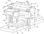
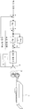
도 1은 본 발명의 실시형태예 1에 따른 수준기를 이용한 기계 변위 보정 시스템에 관한 도면으로서, 상기 수준기의 배치를 도시하는 공작 기계(문형상 상 머시닝 센터)의 사시도,
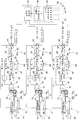
도 2는 본 발명의 실시형태예 1에 따른 수준기를 이용한 기계 변위 보정 시스템에 관한 도면으로서, 보정 장치측의 구성을 도시하는 도면,
도 3은 경사에 의한 기계 변위량의 계산예를 도시하는 도면,
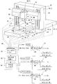
도 4는 본 발명의 실시형태예 2에 따른 수준기를 이용한 기계 변위 보정 시스템에 관한 도면으로서, 상기 수준기의 배치를 도시하는 공작 기계(문형상 머시닝 센터)의 사시도,
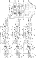
도 5는 본 발명의 실시형태예 2에 따른 수준기를 이용한 기계 변위 보정 시스템에 관한 도면으로서, 보정 장치측의 구성을 도시하는 도면,
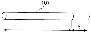
도 6은 온도 변화에 의한 열 변위량의 계산 예를 도시하는 도면,
도 7은 완전 폐쇄 루프의 서보 제어 장치(피드백 제어계)의 구성을 도시하는 블록도,
도 8은 반폐쇄 제어 장치(피드백 제어계)의 구성을 도시하는 블록도,
도 9는 종래의 온도 센서를 이용한 열 변위 보정 시스템의 구성예를 도시하는 도면,
도 10은 종래의 온도 센서를 이용한 열 변위 보정 시스템의 다른 구성예를 도시하는 도면.BRIEF DESCRIPTION OF THE DRAWINGS Fig. 1 is a view of a mechanical displacement correction system using a leveler according to
FIG. 2 is a diagram of a mechanical displacement correction system using a leveler according to
3 is a diagram illustrating an example of calculating the amount of mechanical displacement by tilting;
4 is a view of a mechanical displacement correction system using a leveler according to
FIG. 5 is a diagram of a mechanical displacement correction system using a leveler according to
6 is a diagram illustrating an example of calculating the amount of heat displacement due to temperature change;
7 is a block diagram showing the configuration of a servo control device (feedback control system) in a completely closed loop;
8 is a block diagram showing the configuration of a semi-close control device (feedback control system);
9 is a diagram showing a configuration example of a thermal displacement correction system using a conventional temperature sensor;
10 is a diagram showing another configuration example of a thermal displacement correction system using a conventional temperature sensor.
이하, 본 발명의 실시형태예를 도면에 근거하여 상세하게 설명한다. EMBODIMENT OF THE INVENTION Hereinafter, embodiment of this invention is described in detail based on drawing.
(실시형태예 1)(Example 1)
도 1 내지 도 3에 근거하여, 본 발명의 실시형태예 1에 따른 수준기를 이용한 기계 변위 보정 시스템에 대하여 설명한다. 1 to 3, a mechanical displacement correction system using a leveler according to
도 1에 도시하는 바와 같이, 공작 기계(도시예에서는 문형상 머시닝 센터)는, 베드(51)와, 테이블(52)과, 칼럼(53)과, 크로스 레일(54)과, 새들(56)과, 주축(58)이 내장되어 있는 램(57)을 갖고 있다. As shown in FIG. 1, a machine tool (a door-shaped machining center in the example) includes a
베드(51)상에는 테이블(52)이 설치되고, 테이블(52)상에는 워크(W)가 탑재되어 있다. 테이블(52)은, 이송 기구(도 1에서는 도시 생략·도 2 참조)에 의해, 수평인 X축방향으로 이동 가능하게 되어 있다. 칼럼(53)은 수평부(53A)와, 수평부(53A)의 양측의 각부(脚部)(53B)를 갖고 이루어지는 문형상인 것이며, 베드(51)를 건너지르도록 배설되어 있다. 크로스 레일(54)은, 칼럼(53)의 전방측에 마련되어 있고, 칼럼(53)의 전면(53a)에 마련된 가이드 레일(55)을 따라서, 이송 기구(도시 생략)에 의해, 연직인 W축방향으로 이동 가능하게 되어 있다. 새들(56)은, 크로스 레일(54)의 전방측에 마련되어 있고, 크로스 레일(54)을 따라서, 이송 기구(도 1에서는 도시 생략:도 2 참조)에 의해, 수평인 Y축방향으로 이동 가능하게 되어 있다. 램(57)은, 새들(56)내에 마련되고, 이송 기구(도 1에서는 도시 생략:도 2 참조)에 의해, 연직인 Z축방향으로 이동 가능하게 되어 있다. 또한, X, Y, Z축은 서로 직교하고 있다. The table 52 is provided on the
그리고, 이 공작 기계에는 디지털 수준기(61-1 내지 61-6)가 설치되어 있다. 수준기(61-1, 61-2)는, 칼럼(53)의 표면(53b)의 양단부에 설치되어 있고, 칼럼(53)의 기계 변위에 의해서 생기는 칼럼(53)의 경사의 각도를 검출하여, 경사량 데이터(경사 각도 검출 신호)(c1, c2)를 보정 장치(92)(도 2 참조:상세 후술)에 출력한다.And this machine tool is provided with the digital spirit level 61-1 to 61-6. The spirit level 61-1, 61-2 is provided in the both ends of the
상기 기계 변위에는 열 변위, 자중 변위, 레벨 변위 등에 의한 것이 있다. 열 변위는 주축(58)이나 서보 모터(도 1에서는 도시 생략:도 2 참조) 등의 열원이나 외기의 온도 변화에 의해서 칼럼(53) 등 구조물의 전후나 좌우에 온도차가 생기는 것에 의해, 구조물에 생기는 휨 등의 기계 변위이다. 자중 변위는 구조물의 자중에 의해서 생기는 구조물의 휨이나 쓰러짐 등의 기계 변위이다. 레벨 변위는 베드(51)를 부설하고 있는 레벨(기초)의 변화에 의하여 생기는 구조물의 휨이나 쓰러짐 등의 기계 변위이다. 따라서, 기계 변위에 의해서 칼럼(53) 등의 구조물이 경사지는 경우로서는, 열 변위에 의해서 경사지는 경우와, 자중 변위에 의해서 경사지는 경우와, 레벨 변위에 의해서 경사지는 경우와, 열 변위와 자중 변위와 레벨 변위의 혼성에 의해서 경사지는 경우가 있다. The mechanical displacement may be due to thermal displacement, self-weight displacement, level displacement, or the like. The thermal displacement is caused by a temperature difference between the
수준기(61-3)는, 칼럼(53)의 측면(53c)의 중간의 높이 위치에 설치되어 있고, 칼럼(53)의 기계 변위에 의해서 생기는 칼럼(53)의 경사의 각도를 검출하여, 경사량 데이터(경사 각도 검출 신호)(c3)를 보정 장치(92)에 출력한다. 수준기(61-4, 61-5)는, 크로스 레일(54)의 표면(54a)의 양단부에 설치되어 있고, 크로스 레일(54)의 기계 변위에 의해서 생기는 크로스 레일(54)의 경사의 각도를 검출하여, 경사량 데이터(경사 각도 검출 신호)(c4, c5)를 보정 장치(92)에 출력한다. 수준기(61-6)는, 새들(56)의 상면(56a)에 설치되어 있고, 새들(56)의 기계 변위에 의해서 생기는 새들(56)의 경사의 각도를 검출하여, 경사량 데이터(경사 각도 검출 신호)(c6)를 보정 장치(92)에 출력한다. The leveler 61-3 is provided at an intermediate height position of the
도 2에 도시하는 바와 같이, 보정 장치(92)는 퍼스널 컴퓨터 등을 이용한 것으로서, 경사량 데이터 입력부(93) 기계 변위량 산출부(94)와 보정량 산출부(95)를 갖고 있다.As shown in FIG. 2, the
경사량 데이터 입력부(93)에서는, 수준기(61-1 내지 61-6)로부터 출력되는 각 구조물[칼럼(53), 크로스 레일(54), 새들(56)]의 경사량 데이터(c1 내지 c6)를 입력한다. In the inclination amount
기계 변위량 산출부(94)에서는, 경사량 데이터 입력부(93)에서 입력한 각 구조물[칼럼(53), 크로스 레일(54), 새들(56)]의 경사량 데이터(경사 각도 검출값)에 근거하여, 경사에 의한 각 구조물[칼럼(53), 크로스 레일(54), 새들(56)]의 기계 변위량을 산출한다. In the mechanical displacement
도 3에 근거하여, 칼럼(53)의 기계 변위량의 산출 예에 대하여 설명한다. 도 3(a)에 있어서, H는 칼럼(53)의 높이[m], L은 칼럼(53)의 폭[m], θ는 칼럼(53)의 경사 각도[radiun]이다. 그리고, 칼럼(53)의 기계 변위량(δ)은 하기(1)식에 의해서 산출한다. Based on FIG. 3, the calculation example of the mechanical displacement amount of the
[수 1][1]

(1)식의 도출에 대하여 도 3(b)에 도시한다. 휨이나 쓰러짐 등에 의해, 도 3(b)에 도시하는 원호형상의 기계 변위가 칼럼(53)에 생겼을 경우, 원호의 반경을 R로 하면, 이 반경(R)과, 칼럼 변위량(δ)과 칼럼 높이(H)의 관계는 하기의 (2)식과 같이 된다. 그리고, 이 (2)식을 하기의 (3)식, (4)식, (5)식과 같이 변형하는 것에 의해, (1)식이 도출된다. Derivation of equation (1) is shown in Fig. 3B. In the case where the arc-shaped mechanical displacement shown in Fig. 3 (b) occurs in the
[수 2][Number 2]

또한, (1)식에서 이용하는 칼럼 경사 각도(θ)에는 2개의 수준기(61-1, 61-2)의 경사 각도 검출값[경사량 데이터(c1, c2)]의 평균값을 이용해도 좋고, 어느 한쪽을 이용해도 좋다. 또한, 칼럼(53)의 중간의 높이 위치에 있어서의 칼럼 변위량(δ)을 산출하는 경우에는, 칼럼 경사 각도(θ)로서, 수준기(61-3)의 경사 각도 검출값[경사량 데이터(c3)]을 이용한다. 크로스 레일(54)의 변위량(δ)을 산출하는 경우에는, 크로스 레일 경사 각도(θ)로서, 2개의 수준기(61-4, 61-5)의 경사 각도 검출값[경사량 데이터(c4, c5)]의 평균값을 이용해도 좋고, 어느 한쪽을 이용해도 좋다. 새들(54)의 변위량(δ)을 산출하는 경우에는, 새들 경사 각도로서, 수준기(61-6)의 경사 각도 검출값(경사량 데이터 c6)을 이용한다. In addition, the average value of the inclination-angle detection values (inclination amount data c1, c2) of the two levelers 61-1, 61-2 may be used for the column inclination-angle (theta) used by Formula (1), and either You can also use In addition, when calculating the column displacement amount (delta) in the intermediate height position of the
도 2에 도시하는 바와 같이, 보정량 산출부(95)에서는, 기계 변위량 산출부(94)에서 산출한 각 구조물[칼럼(53), 크로스 레일(54), 새들(56)]의 기계 변위량에 근거하여, 각 이동축(X축, Y축, Z축)에 있어서의 변위량을 산출하고, 이들의 변위량의 역 부호의 값을 각 이동축(X축, Y축, Z축)의 보정량으로 하여, 이들의 보정량을 각 이동축(X축, Y축, Z축)의 서보 제어 장치(81, 82, 83)에 송출한다. 즉, X축의 보정량(="-X의 변위량")은 X축의 서보 제어 장치(81)에 이송하고, Y축의 보정량(="-Y의 변위량")은 Y축의 서보 제어 장치(82)에 이송하며, Z축의 보정량(="-Z의 변위량")은 Z축의 서보 제어 장치(83)에 이송한다. 또한, 구조물의 기계 변위량에 근거하여 이동축의 변위량을 산출하려면, (1)식 등의 이론식을 이용하여 산출해도 좋지만, 예를 들면, 미리 시험이나 시뮬레이션 등에 의해서 구한 구조물의 기계 변위량과 이동축의 변위량의 관계를 나타내는 계산식이나 테이블 데이터 등을 이용해도 좋다. As shown in FIG. 2, in the correction
도 2에 도시하는 바와 같이, X축의 이송 기구(71)는 서보 모터(74), 감속 기어(75), 볼 스크류(76)[나사부(76a), 너트부(76b)]등으로 구성되어 있다.As shown in FIG. 2, the
서보 모터(74)는, 감속 기어(75)를 거쳐서 볼 스크류(76)의 나사부(76a)에 연결되어 있다. 볼 스크류(76)의 나사부(76a)와 너트부(76b)는 서로 나사 결합되어 있으며, 너트부(76b)는 이동체인 테이블(52)에 장착되어 있다. 또한, 테이블(52)에는 위치 검출기(77)가 장착되며, 서보 모터(74)에는 펄스 코더(78)가 장착되어 있다. The
따라서, 서보 모터(74)의 회전력이 감속 기어(75)를 거쳐서 볼 스크류(76)의 나사부(76a)에 전달되어, 나사부(76a)가 화살표(A)와 같이 회전하면, 너트부(76b)와 함께 테이블(52)이 X축방향으로 이동한다. 이 때 테이블(52)의 이동 위치가 위치 검출기(77)에 의해서 검출되고, 이 위치 검출 신호가 X축의 서보 제어 장치(81)로 이송된다(위치 피드백). 또한, 서보 모터(74)의 회전 각도가 펄스 코더(78)에 의해서 검출되고, 이 회전 각도 검출 신호가 서보 제어 장치(81)의 미분 연산부(91)를 거쳐서, 서보 제어 장치(81)로 이송된다(속도 피드백). Therefore, when the rotational force of the
서보 제어 장치(81)는 편차 연산부(84), 곱셈부(85), 편차 연산부(86), 비례 연산부(87), 적분 연산부(88), 가산부(89), 전류 제어부(90), 미분 연산부(91)를 갖고 있다.The
편차 연산부(84)에서는, 수치 제어 장치(도시 생략)로부터 이송된 X축의 위치 지령에 대하여, 보정 장치(92)[보정량 산출부(95)]로부터 이송된 X축의 보정량(="X축의 변위량")을 가산하는 것에 의해, 상기 X축의 위치 지령을 보정하고, 이 보정 후의 X축의 위치 지령과, 위치 검출기(77)로부터의 위치 피드백 정보인 테이블(52)의 위치의 차이를 연산하는 것에 의해, 위치 편차(d1)를 구한다. In the
곱셈부(85)에서는, 위치 편차(d1)에 대하여 위치 루프 게인(Kp)을 곱셈하는 것에 의해, 속도 지령(d2)을 구한다. 미분 연산부(91)에서는, 펄스 코더(78)에 의해서 검출된 서보 모터(74)의 회전 각도를 시간으로 미분하는 것에 의해, 서보 모터(74)의 회전 속도를 구한다. 편차 연산부(86)에서는, 속도 지령(d2)과, 미분 연산부(86)에서 구한 서보 모터(74)의 회전 속도의 차이를 연산하는 것에 의해, 속도 편차(d3)를 구한다. 비례 연산부(87)에서는, 속도 편차(d3)에 대하여 속도 루프 비례 게인(Kv)을 곱셈하는 것에 의해, 비례값(d4)을 구한다. 적분 연산부(88)에서는, 속도 편차(d3)에 대하여 속도 루프 적분 게인(Kvi)을 곱셈하고, 또한, 이 곱셈값을 적분하는 것에 의해, 적분값(d5)을 구한다. 가산부(89)에서는, 비례값(d4)과 적분값(d5)을 가산하여 토크 지령(d6)을 구한다. 전류 제어부(90)에서는, 서보 모터(74)의 토크가 토크 지령(d6)에 추종하도록 서보 모터(74)에 공급하는 전류를 제어한다. In the
따라서, 이 X축의 서보 제어 장치(81)에서는, X축의 서보 모터(74)의 회전 속도가 속도 지령(d2)에 추종하고, 테이블(52)의 X축방향의 이동 위치가 보정 후의 X축의 위치 지령에 추종하도록 제어한다. Therefore, in this X-axis
또한, Y 축과 Z축의 이송 기구(72, 73) 및 서보 제어 장치(82, 83)의 구성에 대해서는, X축의 이송 기구(71) 및 서보 제어 장치(81)의 구성과 동일하기 때문에(동일한 구성 부분에 동일한 부호를 부여하고 있음), 상세한 설명은 생략 한다.The configuration of the
Y축의 서보 제어 장치(82)에서는, 편차 연산부(84)에 있어서, 수치 제어 장치로부터 이송된 Y축의 위치 지령에 대하여, 보정 장치(92)[보정량 산출부(95)]로부터 이송된 Y축의 보정량(="-Y축의 변위량")을 가산하는 것에 의해, 상기 Y축의 위치 지령을 보정하고, 보정 후의 Y축의 위치 지령을 구한다. 그리고, 서보 제어 장치(82)에서는, Y축의 서보 모터(74)의 회전 속도가 속도 지령(d2)에 추종하고, 새들(56)의 Y축방향의 이동 위치가 보정 후의 Y축의 위치 지령에 추종하도록 제어한다.In the Y-axis
Z축의 서보 제어 장치(83)에서는, 편차 연산부(84)에 있어서, 수치 제어 장치로부터 이송된 Z축의 위치 지령에 대하여, 보정 장치(92)[보정량 산출부(95)]로부터 이송된 Z축의 보정량(="-Z축의 변위량")을 가산하는 것에 의해, 상기 Z축의 위치 지령을 보정하고, 보정 후의 Z축의 위치 지령을 구한다. 그리고, 이 서보 제어 장치(83)에서는, Z축의 서보 모터(74)의 회전 속도가, 속도 지령(d2)에 추종하고, 램(57)[주축(58)]의 Z축방향의 이동 위치가, 보정 후의 Z축의 위치 지령에 추종하도록 제어한다. In the
이상으로부터, 본 실시형태예 1의 공작 기계의 기계 변위 보정 시스템에 의하면, 휨, 쓰러짐 등의 기계 변위(열 변위 또는 자중 변위, 혹은, 열 변위 및 자중 변위)에 의해서 공작 기계의 구조물[칼럼(53), 크로스 레일(54), 새들(56)]이 경사졌을 때, 이 구조물의 경사량(경사 각도)을 직접, 수준기(61-1 내지 61-6)에 의해서 파악할 수 있다. 이 때문에, 이 수준기(61-1 내지 61-6)에서 직접 파악한 구조물[칼럼(53), 크로스 레일(54), 새들(56)]의 경사량 데이터(c1 내지 c6)에 근거하여 구조물[칼럼(53), 크로스 레일(54), 새들(56)]의 기계 변위량을 산출하는 것에 의해, 해당 기계 변위량을 정밀도 양호하게 추정할 수 있어 해당 기계 변위량에 근거하여 정밀도 양호한 이동축(X축, Y축, Z축)의 보정량을 얻을 수 있다. 따라서, 고정밀도의 보상 시스템을 실현 가능하다. As mentioned above, according to the mechanical displacement correction system of the machine tool of Example 1, the structure of a machine tool (column ( 53), when the
(실시형태예 2)(Example 2)
도 4 내지 도 6에 근거하여, 본 발명의 실시형태예(2)에 따른 수준기를 이용한 기계 변위 보정 시스템에 대해 설명한다. 또한, 본 실시형태예(2)의 기계 변위 보정 시스템에 있어서, 상기 실시형태예 1의 기계 변위 보정 시스템(도 1, 도 2 참조)과 동일한 부분에 대해서는, 동일 부호를 부여하고, 중복하는 상세한 설명은 생략한다.Based on FIG. 4 thru | or 6, the mechanical displacement correction system using the leveler which concerns on Example (2) of this invention is demonstrated. In addition, in the mechanical displacement correction system of this Embodiment Example 2, the same code | symbol is attached | subjected about the same part as the mechanical displacement correction system of the said Embodiment Example 1 (refer FIG. 1, FIG. 2), and the overlapping detail Description is omitted.
도 4에 도시하는 바와 같이, 본 실시형태예(2)에서는, 공작 기계(문형상 머시닝 센터)에 대하여, 상기 실시형태예 1과 마찬가지로 디지털 수준기(61-1 내지 61-6)를 설치할 뿐만 아니라, 온도 센서(101-1 내지 101-8)도 설치하고 있다.As shown in FIG. 4, in the present embodiment example (2), not only the digital levelers 61-1 to 61-6 are provided to the machine tool (moon-shaped machining center) in the same manner as in the first embodiment. The temperature sensors 101-1 to 101-8 are also provided.
온도 센서(101-1, 101-2)는, 칼럼(53)의 측면(53c)의 상부와 하부에 설치되어 있고, 칼럼(53)의 온도를 검출하여, 온도 데이터(온도 검출 신호)(e1, e2)를 보정 장치(92)(도 5 참조:상세 후술)에 출력한다. 온도 센서(101-3, 101-4)는, 램(57)의 상부와 하부에 설치되어 있고, 램(57)의 온도를 검출하여, 온도 데이터(온도 검출 신호)(e3, e4)를 보정 장치(92)에 출력한다. 온도 센서(101-5)는, 테이블(52)에 설치되어 있고, 테이블(53)의 온도를 검출하여, 온도 데이터(온도 검출 신호)(e5)를 보정 장치(92)에 출력한다. 온도 센서(101-6)는, 워크(W)에 설치되어 있고, 워크(W)의 온도를 검출하여, 온도 데이터(온도 검출 신호)(e6)를 보정 장치(92)에 출력한다. 온도 센서(101-7, 101-8)는, 베드(51)의 전방부와 후방부에 설치되어 있고, 베드(51)의 온도를 검출하여, 온도 데이터(온도 검출 신호)(e7, e8)를 보정 장치(92)에 출력한다. The temperature sensors 101-1 and 101-2 are provided in the upper part and the lower part of the
도 5에 도시하는 바와 같이, 본 실시형태예(2)의 보정 장치(92)는, 상기 실시형태예 1과 마찬가지로 경사량 데이터 입력부(93)와 기계 변위량 산출부(94)와 보정량 산출부(95)(제 1 보정량 산출부)를 갖고 있을 뿐만 아니라, 온도 데이터 입력부(103)와 열 변위량 산출부(104)와 보정량 산출부(105)(제 2 보정량 산출부)와 보정량 가산부(106)도 갖고 있다. As shown in FIG. 5, the
온도 데이터 입력부(103)에서는, 온도 센서(101-1 내지 101-8)로부터 출력되는 각 구조물[칼럼(53), 램(57), 테이블(52), 베드(51)] 및 워크(W)의 온도 데이터(e1 내지 e8)를 입력한다. In the temperature
열 변위량 산출부(104)에서는, 온도 데이터 입력부(103)에서 입력한 각 구조물[칼럼(53), 램(57), 테이블(52), 베드(51)] 및 워크(W)의 온도 데이터(온도 검출값)에 근거하여, 각 구조물[칼럼(53), 램(57), 테이블(52), 베드(51)]이나 워크(W)의 열 변위량을 산출한다. In the thermal
도 6에 근거하여, 칼럼(53), 램(57) 등에 상당하는 물체(107)의 열 변위량의 산출예에 대하여 설명하면, 물체(107)의 열 변위량(열에 의한 연장량) δ은 하기의 (6)식에 의해서 산출한다. 도 6 및 (6)식에 있어서, L은 물체(107)의 유효 길이[m], △T는 물체(107)의 온도 변화[℃](=T-T0), β는 물체(107)의 선팽창 계수[m/℃*m][물체(107)의 1[m] 당의 1[℃] 변화시의 변위량]이다. 또한, T는 물체(107)의 온도[℃], T0는 물체(107)의 기준 온도[℃]이다.Referring to the calculation example of the thermal displacement amount of the
δ=△T*L*β … (6)δ = ΔT * L * β... (6)
물체(107)의 온도(T)에는, 온도 센서(101-1 내지 101-8)로부터 입력한 온도 데이터(e1 내지 e8)를 이용한다. 물체(107)의 기준 온도는 열 변위량 산출부(104)에 미리 설정해 둔다. 또한, 칼럼(53)의 열 변위량을 산출하기 위한 온도 데이터에는, 2개의 온도 센서(101-1, 101-2)의 온도 검출값[온도 데이터(e1, a2)]의 평균값을 이용해도 좋고, 어느 한쪽을 이용해도 좋다. 램(57)의 열 변위량을 산출하기 위한 온도 데이터에는, 2개의 온도 센서(101-3, 101-4)의 온도 검출값(온도 데이터 e3, e4)의 평균값을 이용해도 좋고, 어느 한쪽을 이용해도 좋다. 테이블(52)의 열 변위량을 산출하기 위한 온도 데이터에는, 온도 센서(101-5)의 온도 검출값(온도 데이터 e5)을 이용한다. 워크(W)의 열 변위량을 산출을 위한 온도 데이터에는, 온도 센서(101-6)의 온도 검출값[온도 데이터 (e6)]을 이용한다. 베드(51)의 열 변위량을 산출을 위한 온도 데이터에는, 2개의 온도 센서(101-7, 101-8)의 온도 검출값(온도 데이터 e7, e8)의 평균값을 이용해도 좋고, 어느 한쪽을 이용해도 좋다. The temperature data e1 to e8 input from the temperature sensors 101-1 to 101-8 are used for the temperature T of the
도 5에 도시하는 바와 같이, 보정량 산출부(105)에서는, 열 변위량 산출부(104)에서 산출한 각 구조물[칼럼(53), 램(57), 테이블(52), 베드(51)]이나 워크(W)의 열 변위량에 근거하여, 각 이동축(X축, Y축, Z축)에 있어서의 변위량을 산출하고, 이들의 변위량의 역 부호의 값을 각 이동축(X축, Y축, Z축)의 보정량으로 한다. 즉, X축의 보정량(="-X축의 변위량")과 Y축의 보정량(="-Y축의 변위량")과 Z축의 보정량(="-Z축의 변위량")을 구한다. 또한, 구조물의 열 변위량으로부터 이동축의 변위량을 산출하려면, (6)식 등의 이론식을 이용하여 산출해도 좋지만, 예를 들면, 미리 시험이나 시뮬레이션 등에 의해서 구한 구조물의 열 변위량과 이동축의 변위량의 관계를 나타내는 계산식이나 테이블 데이터 등을 이용해도 좋다. As shown in FIG. 5, in the correction
보정량 가산부(106)에서는, 보정량 산출부(95)에서 산출한 각 이동축(X축, Y축, Z축)의 보정량(제 1 보정량)과 보정량 산출부(105)에서 산출한 각 이동축(X축, Y축, Z축)의 보정량(제 2 보정량)을 가산하여, 이 가산값을 각 이동축(X축, Y축, Z축)의 서보 제어 장치(81, 82, 83)에 각각 송출한다.In the correction
즉, X축의 서보 제어 장치(81)에 이송되는 X축의 보정량은, 제 1 보정량 산출부(95)에서 산출한 X축의 제 1 보정량과, 제 2 보정량 산출부(105)에서 산출한 X축의 제 2 보정량의 가산값이다. Y축의 서보 제어 장치(82)에 이송되는 Y축의 보정량은, 제 1 보정량 산출부(95)에서 산출한 Y축의 제 1 보정량과 제 2 보정량 산출부(105)에서 산출한 Y축의 제 2 보정량의 가산값이다. Z축의 서보 제어 장치(83)에 이송되는 Z축의 보정량은, 제 1 보정량 산출부(95)에서 산출한 Z축의 제 1 보정량과, 제 2 보정량 산출부(105)에서 산출한 Z축의 제 2 보정량의 가산값이다. That is, the correction amount of the X axis transferred to the
X축의 서보 제어 장치(81)의 편차 연산부(84)에서는, 수치 제어 장치(도시 생략)로부터 이송된 X축의 위치 지령에 대하여, 보정 장치(92)[보정량 가산부(106)]로부터 이송된 X축의 보정량(="-X축의 변위량")을 가산하는 것에 의해, 상기 X축의 위치 지령을 보정하고, 이 보정 후의 X축의 위치 지령과, 위치 검출기(77)로부터의 위치 피드백 정보인 테이블(52)의 위치의 차이를 연산하는 것에 의해, 위치 편차(d1)를 구한다.In the
Y축의 서보 제어 장치(82)의 편차 연산부(84)에서는, 수치 제어 장치로부터 이송된 Y축의 위치 지령에 대하여, 보정 장치(92)[보정량 가산부(106)]로부터 이송된 Y축의 보정량[="-Y축의 변위량"]을 가산하는 것에 의해, 상기 Y축의 위치 지령을 보정하고, 이 보정 후의 X축의 위치 지령과, 위치 검출기(77)로부터의 위치 피드백 정보인 새들(56)의 위치의 차이를 연산하는 것에 의해, 위치 편차(d1)를 구한다.In the
Z축의 서보 제어 장치(83)의 편차 연산부(84)에서는, 수치 제어 장치로부터 이송된 Z축의 위치 지령에 대하여, 보정 장치(92)[보정량 가산부(106)]로부터 이송된 Z축의 보정량[="-Z축의 변위량"]을 가산하는 것에 의해, 상기 Z축의 위치 지령을 보정하고, 이 보정 후의 Z축의 위치 지령과, 위치 검출기(77)로부터의 위치 피드백 정보인 램(57)[주축(58)]의 위치의 차이를 연산하는 것에 의해, 위치 편차(d1)를 구한다. In the
이상으로부터, 본 실시형태예(2)의 공작 기계의 기계 변위 보정 시스템에 의하면, 상기 실시형태예 1과 마찬가지로, 휨, 쓰러짐 등의 기계 변위(열 변위 또는 자중 변위, 혹은, 열 변위 및 자중 변위)에 의해서 공작 기계의 구조물[칼럼(53), 크로스 레일(54), 새들(56)]이 경사졌을 때, 이 구조물의 경사량(경사 각도)을, 직접 수준기(61-1 내지 61-6)에 의해서 파악할 수 있기 때문에, 이 수준기(61-1 내지 61-6)에서 직접 파악한 구조물[칼럼(53), 크로스 레일(54), 새들(56)]의 경사량 데이터(c1 내지 c6)에 근거하여 구조물[칼럼(53), 크로스 레일(54), 새들(56)]의 기계 변위량을 산출하는 것에 의해, 해당 기계 변위량을 정밀도 양호하게 추정할 수 있어, 해당 기계 변위량에 근거하여 정밀도가 양호한 이동축(X축, Y축, Z축)의 제 1 보정량을 얻을 수 있다.As mentioned above, according to the mechanical displacement correction system of the machine tool of Example 2 of this embodiment, similarly to
게다가, 본 실시형태예(2)에서는, 이 이동축(X축, Y축, Z축)의 제 1 보정량에 대하여, 온도 센서(101-1 내지 101-8)의 온도 데이터(e1 내지 e8)에 근거하여 구한 이동축(X축, Y축, Z축)의 제 2 보정량을 가산하는 것에 의해, 휨이나 쓰러짐 등의 기계 변위뿐만이 아니라, 열에 의한 구조물[칼럼(53), 램(57), 테이블(52), 베드(51)]이나 워크(W)의 성장 등의 열 변위에도 대응할 수 있기 때문에, 보다 정밀도 양호한 이동축(X축, Y축, Z축)의 보정량을 얻을 수 있다. 따라서, 보다 고정밀도의 보상 시스템을 실현 가능하다. In addition, in the example (2) of this embodiment, the temperature data (e1 to e8) of the temperature sensors 101-1 to 101-8 with respect to the first correction amount of this moving axis (X-axis, Y-axis, Z-axis). By adding the second correction amounts of the moving axes (X-axis, Y-axis, Z-axis) obtained based on the structure, not only mechanical displacements such as warping and falling down, but also structures by heat (
또한, 상기 실시형태 예 1, 2에서는 수준기를 이용했지만, 반드시 이것에 한정하는 것이 아니고, 공작 기계의 구조물의 경사 각도를 직접 검출 가능한 것이면, 수준기 이외의 경사 각도 검출기라도 좋다. In addition, although the leveler was used in the said Example 1, 2, it is not necessarily limited to this, As long as it can detect the inclination angle of the structure of a machine tool directly, inclination angle detectors other than a leveler may be sufficient.
[산업상의 이용 가능성][Industrial Availability]
본 발명은 공작 기계의 기계 변위 보정 시스템에 관한 것이며, 공작 기계의 칼럼 등에 생기는 기계 변위(열 변위, 자중 변위, 레벨 변위)를 보정하는 경우에 적용하여 유용한 것이다.BACKGROUND OF THE
51 : 베드 52 : 테이블
53 : 칼럼 53A : 수평부
53B : 각부 53a 전면
53b : 상면 53c : 측면
54 : 크로스 레일 54a : 상면
55 : 가이드 레일 56 : 새들
56a : 상면 57 : 램
58 : 주축 61-1 내지 61-6 : 수준기
71, 72, 73 : 이송 기구 74 : 서보 모터
75 : 감속 기어 76 : 볼 스크류
76a : 나사부 76b : 너트부
77 : 위치 검출기 78 : 펄스 코더
81, 82, 83 : 서보 제어 장치 84 : 편차 연산부
85 : 곱셈부 86 : 편차 연산부
87 : 비례 연산부 88 : 적분 연산부
89 : 가산부 90 : 전류 제어부
91 : 미분 연산부 92 : 보정 장치
93 : 경사량 데이터 입력부 94 : 기계 변위량 산출부
95 : 보정량 산출부 101-1 내지 101-8 : 온도 센서
103 : 온도 데이터 입력부, 104 : 열 변위량 산출부
105 : 보정량 산출부 106 : 보정량 가산부
c1 내지 c6 : 경사량 데이터(경사 각도 검출 신호)
e1 내지 e8 : 온도 데이터(온도 검출 신호)
W : 워크51: Bed 52: Table
53:
53B:
53b:
54:
55: guide rail 56: saddle
56a: top face 57: ram
58: main shaft 61-1 to 61-6: spirit level
71, 72, 73: transfer mechanism 74: servo motor
75: reduction gear 76: ball screw
76a:
77: position detector 78: pulse coder
81, 82, 83: servo control device 84: deviation calculator
85: multiplication unit 86: deviation calculation unit
87: proportional calculation unit 88: integral calculation unit
89: adding unit 90: current control unit
91: derivative operation unit 92: correction device
93: tilt amount data input unit 94: mechanical displacement amount calculation unit
95: correction amount calculation unit 101-1 to 101-8: temperature sensor
103: temperature data input unit, 104: thermal displacement calculation unit
105: correction amount calculation unit 106: correction amount adding unit
c1 to c6: Inclination amount data (inclined angle detection signal)
e1 to e8: temperature data (temperature detection signal)
W: Walk
Claims (2)
상기 공작 기계의 구조물에 설치되고, 상기 구조물의 경사 각도를 검출하여 경사량 데이터를 출력하는 경사 각도 검출기와,
상기 경사 각도 검출기로부터 상기 경사량 데이터를 입력하는 경사량 데이터 입력부와, 상기 경사량 데이터 입력부에서 입력한 상기 경사량 데이터에 근거하여 상기 구조물의 기계 변위량을 산출하는 기계 변위량 산출부와, 상기 기계 변위량 산출부에서 산출한 상기 구조물의 기계 변위량에 근거하여 상기 공작 기계의 이동축의 보정량을 산출하는 보정량 산출부를 갖는 보정 장치를 구비한 것을 특징으로 하는
공작 기계의 기계 변위 보정 시스템. In the machine displacement correction system for correcting the machine displacement of the machine tool,
An inclination angle detector installed in the structure of the machine tool and detecting an inclination angle of the structure and outputting inclination amount data;
An inclination amount data input unit for inputting the inclination amount data from the inclination angle detector, a mechanical displacement amount calculating unit for calculating a mechanical displacement amount of the structure based on the inclination amount data input by the inclination amount data input unit, and the mechanical displacement amount And a correction device having a correction amount calculation unit for calculating a correction amount of the moving shaft of the machine tool based on the mechanical displacement amount of the structure calculated by the calculation unit.
Machine displacement compensation system of machine tools.
상기 공작 기계의 구조물에 설치되고, 상기 구조물의 경사 각도를 검출하여 경사량 데이터를 출력하는 경사 각도 검출기와,
상기 공작 기계의 구조물 또는 워크에 설치되고, 상기 구조물 또는 상기 워크의 온도를 검출하여 온도 데이터를 출력하는 온도 센서와,
상기 경사 각도 검출기로부터 상기 경사량 데이터를 입력하는 경사량 데이터 입력부와, 상기 경사량 데이터 입력부에서 입력한 상기 경사량 데이터에 근거하여 상기 구조물의 기계 변위량을 산출하는 기계 변위량 산출부와, 상기 기계 변위량 산출부에서 산출한 상기 구조물의 기계 변위량에 근거하여 상기 공작 기계의 이동축의 제 1 보정량을 산출하는 제 1 보정량 산출부와, 상기 온도 센서로부터 상기 온도 데이터를 입력하는 온도 데이터 입력부와, 상기 온도 데이터 입력부에서 입력한 상기 온도 데이터에 근거하여 상기 구조물 또는 상기 워크의 열 변위량을 산출하는 열 변위량 산출부와, 상기 열 변위량 산출부에서 산출한 상기 구조물 또는 상기 워크의 열 변위량에 근거하여 상기 이동축의 제 2 보정량을 산출하는 제 2 보정량 산출부와, 상기 제 1 보정량 산출부에서 산출한 상기 제 1 보정량과 상기 제 2 보정량 산출부에서 산출한 상기 제 2 보정량을 가산하는 보정량 가산부를 갖는 보정 장치를 구비한 것을 특징으로 하는
공작 기계의 기계 변위 보정 시스템.
In the machine displacement correction system for correcting the machine displacement of the machine tool,
An inclination angle detector installed in the structure of the machine tool and detecting an inclination angle of the structure and outputting inclination amount data;
A temperature sensor installed in a structure or a work of the machine tool and detecting temperature of the structure or the work and outputting temperature data;
An inclination amount data input unit for inputting the inclination amount data from the inclination angle detector, a mechanical displacement amount calculating unit for calculating a mechanical displacement amount of the structure based on the inclination amount data input by the inclination amount data input unit, and the mechanical displacement amount A first correction amount calculation unit that calculates a first correction amount of the moving shaft of the machine tool based on the mechanical displacement amount of the structure calculated by the calculation unit, a temperature data input unit which inputs the temperature data from the temperature sensor, and the temperature data A heat displacement calculation unit configured to calculate a heat displacement amount of the structure or the workpiece based on the temperature data inputted from an input unit, and a displacement of the moving shaft based on the heat displacement amount of the structure or the workpiece calculated by the heat displacement calculation unit. A second correction amount calculating unit for calculating a second correction amount; And a correction device having a correction amount adding unit for adding the first correction amount calculated by the first correction amount calculating unit and the second correction amount calculated by the second correction amount calculating unit.
Machine displacement compensation system of machine tools.
Applications Claiming Priority (2)
| Application Number | Priority Date | Filing Date | Title |
|---|---|---|---|
| JPJP-P-2010-002631 | 2010-01-08 | ||
| JP2010002631A JP2011140098A (en) | 2010-01-08 | 2010-01-08 | Machine displacement correction system for machine tool |
Publications (1)
| Publication Number | Publication Date |
|---|---|
| KR20120073312A true KR20120073312A (en) | 2012-07-04 |
Family
ID=44305338
Family Applications (1)
| Application Number | Title | Priority Date | Filing Date |
|---|---|---|---|
| KR1020127011071A KR20120073312A (en) | 2010-01-08 | 2010-09-15 | Machine displacement adjustment system for machine tools |
Country Status (6)
| Country | Link |
|---|---|
| US (1) | US20120271439A1 (en) |
| JP (1) | JP2011140098A (en) |
| KR (1) | KR20120073312A (en) |
| CN (1) | CN102596496A (en) |
| TW (1) | TW201124230A (en) |
| WO (1) | WO2011083596A1 (en) |
Families Citing this family (16)
| Publication number | Priority date | Publication date | Assignee | Title |
|---|---|---|---|---|
| ITBS20120010A1 (en) * | 2012-01-26 | 2013-07-27 | Innse Berardi S P A Societa Unipe Rsonale | POSITIONING SYSTEM ON A TABLE HOLDER OF A TOOL MACHINE AND METHOD OF POSITIONING THE PIECE ON THE TABLE |
| JP5252102B1 (en) * | 2012-04-03 | 2013-07-31 | 株式会社安川電機 | Motor control device, motor control system, and cutting device |
| JP2016078177A (en) * | 2014-10-17 | 2016-05-16 | 三菱重工業株式会社 | Machine tool |
| CN104698974B (en) * | 2015-02-11 | 2017-12-15 | 北京配天技术有限公司 | A kind of Digit Control Machine Tool and its adjustment method |
| KR20170058334A (en) * | 2015-03-17 | 2017-05-26 | 도시바 기카이 가부시키가이샤 | Machine tool |
| JP6331225B2 (en) * | 2015-08-19 | 2018-05-30 | 株式会社安川電機 | Motor control device, position control system, and motor control method |
| JP6724622B2 (en) * | 2015-10-08 | 2020-07-15 | 東京エレクトロン株式会社 | Horizontal installation device and horizontal installation method of installation object |
| JP2017087357A (en) * | 2015-11-11 | 2017-05-25 | ファナック株式会社 | Automatic position adjustment system for installation object |
| KR102123173B1 (en) * | 2016-03-28 | 2020-06-15 | 두산공작기계 주식회사 | Automatic conversion device for thermal displacement compensation parameters and conversion method for machine tools |
| JP6955655B2 (en) * | 2016-11-14 | 2021-10-27 | 株式会社ニイガタマシンテクノ | Machine tool temperature control device |
| JP6856469B2 (en) * | 2017-07-19 | 2021-04-07 | ファナック株式会社 | Servo motor controller |
| CN108214303B (en) * | 2018-03-22 | 2020-02-21 | 宁波弘讯科技股份有限公司 | Lead screw output error correction method and grinding machine |
| JP6737840B2 (en) * | 2018-06-19 | 2020-08-12 | ファナック株式会社 | Adjustment necessity judgment device |
| IT201800007230A1 (en) * | 2018-07-16 | 2020-01-16 | NUMERICAL CONTROL MACHINE TOOL | |
| CN109290843B (en) * | 2018-11-16 | 2021-02-05 | 西安科技大学 | Method for predicting reversing error peak value of inclined feeding system of precision numerical control machine tool |
| CN109739182B (en) * | 2019-01-31 | 2020-06-16 | 大连理工大学 | Spindle thermal error compensation method insensitive to cooling system disturbance |
Family Cites Families (12)
| Publication number | Priority date | Publication date | Assignee | Title |
|---|---|---|---|---|
| EP1164550B1 (en) * | 2000-06-16 | 2008-12-03 | Ntn Corporation | Machine component monitoring, diagnosing and selling system |
| EP1308239A3 (en) * | 2001-10-31 | 2005-08-10 | GROB-Werke Burkhart Grob e.K. | Machine tool and method for adjusting the position of the spindle of the machine |
| JP4299761B2 (en) * | 2004-10-22 | 2009-07-22 | ヤマザキマザック株式会社 | Thermal displacement correction method and thermal displacement correction apparatus for machine tool |
| JP2006239854A (en) * | 2005-02-04 | 2006-09-14 | Nagase Integrex Co Ltd | Machine tool |
| JP4760091B2 (en) * | 2005-03-30 | 2011-08-31 | ブラザー工業株式会社 | Machine tool and displacement correction method for machine tool |
| JP4469325B2 (en) * | 2005-11-04 | 2010-05-26 | 株式会社森精機製作所 | Thermal displacement correction device |
| JP4972925B2 (en) * | 2005-12-19 | 2012-07-11 | ブラザー工業株式会社 | Temperature measurement position determination method for machine tool and temperature measurement position determination program for machine tool |
| ES2328646T3 (en) * | 2006-03-02 | 2009-11-16 | Mikron Agie Charmilles Ag | METHOD AND APPLIANCE TO CORRECT THE DISPLACEMENT OF A TOOL MACHINE. |
| JP2008155339A (en) * | 2006-12-26 | 2008-07-10 | Mitsubishi Heavy Ind Ltd | Main spindle perpendicularity detecting device, and work machine equipped with the same |
| JP4891104B2 (en) * | 2007-01-29 | 2012-03-07 | オークマ株式会社 | Thermal displacement estimation method for machine tools |
| JP5399624B2 (en) * | 2007-10-22 | 2014-01-29 | オークマ株式会社 | Numerical control method and numerical control device |
| JP5001870B2 (en) * | 2008-02-07 | 2012-08-15 | 三菱重工業株式会社 | Machine Tools |
-
2010
- 2010-01-08 JP JP2010002631A patent/JP2011140098A/en active Pending
- 2010-09-15 CN CN2010800495964A patent/CN102596496A/en active Pending
- 2010-09-15 US US13/504,914 patent/US20120271439A1/en not_active Abandoned
- 2010-09-15 KR KR1020127011071A patent/KR20120073312A/en not_active Application Discontinuation
- 2010-09-15 WO PCT/JP2010/065911 patent/WO2011083596A1/en active Application Filing
- 2010-09-27 TW TW099132669A patent/TW201124230A/en unknown
Also Published As
| Publication number | Publication date |
|---|---|
| TW201124230A (en) | 2011-07-16 |
| WO2011083596A1 (en) | 2011-07-14 |
| US20120271439A1 (en) | 2012-10-25 |
| JP2011140098A (en) | 2011-07-21 |
| CN102596496A (en) | 2012-07-18 |
Similar Documents
| Publication | Publication Date | Title |
|---|---|---|
| KR20120073312A (en) | Machine displacement adjustment system for machine tools | |
| US20130223946A1 (en) | System for correcting thermal displacement of machine tool | |
| JP5512954B2 (en) | Position control device for numerical control machine | |
| JP4359573B2 (en) | Machine tool thermal displacement compensation method | |
| TWI435517B (en) | Load inertia estimation method and control parameter adjustment method | |
| JP5418272B2 (en) | Thermal displacement correction method and thermal displacement correction apparatus for machine tool | |
| JP4559277B2 (en) | NC machine tool thermal displacement compensation method | |
| TW200938329A (en) | Machine tool | |
| US10247301B2 (en) | Servo control system with position compensation function for driven member | |
| KR20090086609A (en) | Spindle tilting detection device and machine tool provided with this | |
| US10274927B2 (en) | Method of machining workpiece using machine tool, and machine tool | |
| JP4598617B2 (en) | Position control device for numerical control machine | |
| JP6299184B2 (en) | Machine tool and machining control method in machine tool | |
| KR20140128444A (en) | Laser machining device | |
| JP5972553B2 (en) | Positioning control device and machine tool equipped with the same | |
| JP6463926B2 (en) | Displacement compensation system for machine tools | |
| WO2016147979A1 (en) | Machine tool | |
| TW201832456A (en) | Work conveyance control system and motion guide device | |
| JP4082598B2 (en) | Method and apparatus for correcting thermal displacement of numerically controlled machine tool | |
| JP2008059016A (en) | Positioning controller and positioning control method | |
| JP7193361B2 (en) | position controller | |
| JP3937078B2 (en) | Robot control apparatus and control method | |
| Kronthaler et al. | Model based control of a high precision dual gantry platform with elastic cross coupling | |
| KR20170079274A (en) | Device for compensating thermal displacement of feed driver for a machine tool and method thereof | |
| JP2006011752A (en) | Cutting resistance estimation method for parallel mechanism type machine tool |
Legal Events
| Date | Code | Title | Description |
|---|---|---|---|
| A201 | Request for examination | ||
| E902 | Notification of reason for refusal | ||
| E601 | Decision to refuse application |