KR20120072479A - Belt conveyor - Google Patents
Belt conveyor Download PDFInfo
- Publication number
- KR20120072479A KR20120072479A KR1020100134247A KR20100134247A KR20120072479A KR 20120072479 A KR20120072479 A KR 20120072479A KR 1020100134247 A KR1020100134247 A KR 1020100134247A KR 20100134247 A KR20100134247 A KR 20100134247A KR 20120072479 A KR20120072479 A KR 20120072479A
- Authority
- KR
- South Korea
- Prior art keywords
- carriage roller
- belt conveyor
- frame
- stand
- roller
- Prior art date
Links
Images


Classifications
-
- B—PERFORMING OPERATIONS; TRANSPORTING
- B65—CONVEYING; PACKING; STORING; HANDLING THIN OR FILAMENTARY MATERIAL
- B65G—TRANSPORT OR STORAGE DEVICES, e.g. CONVEYORS FOR LOADING OR TIPPING, SHOP CONVEYOR SYSTEMS OR PNEUMATIC TUBE CONVEYORS
- B65G15/00—Conveyors having endless load-conveying surfaces, i.e. belts and like continuous members, to which tractive effort is transmitted by means other than endless driving elements of similar configuration
- B65G15/08—Conveyors having endless load-conveying surfaces, i.e. belts and like continuous members, to which tractive effort is transmitted by means other than endless driving elements of similar configuration the load-carrying surface being formed by a concave or tubular belt, e.g. a belt forming a trough
-
- B—PERFORMING OPERATIONS; TRANSPORTING
- B65—CONVEYING; PACKING; STORING; HANDLING THIN OR FILAMENTARY MATERIAL
- B65G—TRANSPORT OR STORAGE DEVICES, e.g. CONVEYORS FOR LOADING OR TIPPING, SHOP CONVEYOR SYSTEMS OR PNEUMATIC TUBE CONVEYORS
- B65G15/00—Conveyors having endless load-conveying surfaces, i.e. belts and like continuous members, to which tractive effort is transmitted by means other than endless driving elements of similar configuration
- B65G15/60—Arrangements for supporting or guiding belts, e.g. by fluid jets
-
- B—PERFORMING OPERATIONS; TRANSPORTING
- B65—CONVEYING; PACKING; STORING; HANDLING THIN OR FILAMENTARY MATERIAL
- B65G—TRANSPORT OR STORAGE DEVICES, e.g. CONVEYORS FOR LOADING OR TIPPING, SHOP CONVEYOR SYSTEMS OR PNEUMATIC TUBE CONVEYORS
- B65G21/00—Supporting or protective framework or housings for endless load-carriers or traction elements of belt or chain conveyors
- B65G21/20—Means incorporated in, or attached to, framework or housings for guiding load-carriers, traction elements or loads supported on moving surfaces
-
- B—PERFORMING OPERATIONS; TRANSPORTING
- B65—CONVEYING; PACKING; STORING; HANDLING THIN OR FILAMENTARY MATERIAL
- B65G—TRANSPORT OR STORAGE DEVICES, e.g. CONVEYORS FOR LOADING OR TIPPING, SHOP CONVEYOR SYSTEMS OR PNEUMATIC TUBE CONVEYORS
- B65G23/00—Driving gear for endless conveyors; Belt- or chain-tensioning arrangements
- B65G23/02—Belt- or chain-engaging elements
- B65G23/04—Drums, rollers, or wheels
- B65G23/08—Drums, rollers, or wheels with self-contained driving mechanisms, e.g. motors and associated gearing
-
- B—PERFORMING OPERATIONS; TRANSPORTING
- B65—CONVEYING; PACKING; STORING; HANDLING THIN OR FILAMENTARY MATERIAL
- B65G—TRANSPORT OR STORAGE DEVICES, e.g. CONVEYORS FOR LOADING OR TIPPING, SHOP CONVEYOR SYSTEMS OR PNEUMATIC TUBE CONVEYORS
- B65G69/00—Auxiliary measures taken, or devices used, in connection with loading or unloading
- B65G69/18—Preventing escape of dust
-
- B—PERFORMING OPERATIONS; TRANSPORTING
- B65—CONVEYING; PACKING; STORING; HANDLING THIN OR FILAMENTARY MATERIAL
- B65G—TRANSPORT OR STORAGE DEVICES, e.g. CONVEYORS FOR LOADING OR TIPPING, SHOP CONVEYOR SYSTEMS OR PNEUMATIC TUBE CONVEYORS
- B65G2203/00—Indexing code relating to control or detection of the articles or the load carriers during conveying
- B65G2203/04—Detection means
- B65G2203/042—Sensors
Abstract
Description
본 발명은 이송물에 포함된 이물질을 쉽게 제거할 수 있도록 한 벨트컨베이어 장치에 관한 것이다.
The present invention relates to a belt conveyor device that can easily remove the foreign matter contained in the conveyed material.
일반적으로 벨트컨베이어는 대규모로 연, 원료 등의 이송물을 이송하기 위해 사용된다.In general, belt conveyors are used to transport feeds such as lead and raw materials on a large scale.
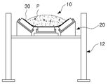
도 1은 일반적인 벨트컨베이어 장치를 간략하게 도시한 구성도이고, 도 2는 종래 기술에 따른 벨트컨베이어 장치의 정면도이다.1 is a configuration diagram briefly showing a general belt conveyor device, Figure 2 is a front view of a belt conveyor device according to the prior art.
도 1과 도 2를 참고하면, 벨트컨베이어(10)는 일측이 작업장 또는 다른 벨트컨베이어 등과 연결되고, 타측에는 리크레이머(reclaimer)(1) 등과 같은 설비에 의해 이송물이 공급되도록 이루어진다.1 and 2, the
이러한 벨트컨베이어(10)는 이송물의 이송선상을 따라 양측으로 스탠드(12)가 설치되고, 이 스탠드(12)에는 캐리지 롤러(20)에 의해 이동되는 벨트(30)가 제공될 수 있다.The
이때 캐리지 롤러(20)는 복수개로 이루어져 양측이 가운데로 향하도록 경사지게 제공되며, 이에 따라 이송물들이 벨트컨베이어(10)의 중앙부를 향하여 오목하게 적재된 상태로 이송될 수 있다.At this time, the
한편, 벨트컨베이어(10)는 이송물을 적재하는 과정에서 철편 등과 같은 이물질(P)이 함께 유입되어 이송될 수 있다.On the other hand, the
이러한 이물질(P)은 이송되는 과정에서 벨트컨베이어(10)의 벨트(30)를 손상시킬 수 있으므로, 벨트컨베이어(10)의 이동선상에는 이물질(P)을 감지하기 위한 (도시되지 않은) 감지기가 설치된다.Since the foreign matter P may damage the
그런데, 종래에는 감지기가 철편 등의 이물질(P)을 감지하게 되면, 벨트컨베이어(10)의 작동을 중지하고 작업자가 직접 철편 수거용 수공구를 들고 벨트컨베이어(10)로 올라가 이물질(P)을 분리 및 제거하고 있다.By the way, conventionally, when the detector detects a foreign material (P) such as iron, stop the operation of the belt conveyor (10) and the worker directly lifts the hand tool for collecting the iron piece to go up to the belt conveyor (10) to separate the foreign matter (P) and It is being removed.
그러나, 감지기는 이송물 중에 철편 등의 이물질(P)이 포함된 여부만을 감지할 수 있다. 또한, 종래의 벨트컨베이어(10)는 감지기에 의해 이물질(P)이 감지된 후, 작동이 중지되더라도 관성 등에 의해 소정 거리 이동하여 멈추게 되므로 작업자가 이물질(P)을 수거하기 위해서는 감지기 주변의 이송물을 뒤지면서 이물질(P)을 찾아야 하는 불편함이 있다.However, the detector can only detect whether the foreign matter (P) such as iron pieces in the conveyed material. In addition, the
더욱이 벨트컨베이어(10)는 내측을 향해 경사지게 배치되는바 작업자가 벨트컨베이어(10)를 따라 이동하기가 쉽지 않았고, 이에 따라 작업자가 이동하는 과정에서 발이 빠지거나 이송물 등에 파묻혀 상해를 입을 우려가 있다.In addition, the
또한, 종래에는 벨트컨베이어(10)의 중앙부에 적재된 이송물의 깊이가 깊어서 작업이 쉽지 않다. 이에 따라 종래에는 이물질(P)이 이송물에 깊이 묻혀있을 경우 작업을 위해 주변으로 이송시켜야 하는 불편함이 있고, 주변으로 이동된 이송물이 다시 흘러내려 제거작업속도를 더욱 지연시키는 요인이 되고 있다.In addition, conventionally, the depth of the conveyed material loaded in the central portion of the
이와 같이, 종래에는 벨트컨베이어(10)를 통해 이송되는 이송물에 포함된 이물질(P)을 찾는 시간이 과다하게 소요되어 전체적인 작업생산성을 저하시키는 요인이 되고 있다.
As such, in the related art, the time required to find the foreign matter P contained in the conveyed material conveyed through the
본 발명의 일 실시예는 벨트컨베이어로 이송되는 이송물에 이물질이 감지될 경우, 벨트컨베이어가 이물질 감지에 용이한 형태로 변형되도록 한 벨트컨베이어 장치를 제공하는 것을 목적으로 한다.
One embodiment of the present invention is to provide a belt conveyor device that the belt conveyor is deformed in a form that is easy to detect the foreign matter when the foreign matter is detected in the conveyed material conveyed to the belt conveyor.
본 발명의 일 측면에 따른 벨트컨베이어 장치는 이송물의 이송선상에 설치되는 스탠드; 스탠드의 상부에 설치된 수평 캐리지 롤러; 수평 캐리지 롤러의 좌, 우측에 일측을 축으로 회전 가능하게 설치된 한 쌍의 경사 캐리지 롤러; 및 경사 캐리지 롤러의 타측에 각각 설치되어 경사 캐리지 롤러를 수평 또는 경사지도록 회전시키는 구동부;를 포함한다.Belt conveyor apparatus according to an aspect of the present invention is a stand installed on the transport line of the conveyed material; A horizontal carriage roller installed at the top of the stand; A pair of inclined carriage rollers rotatably installed at one side on the left and right sides of the horizontal carriage roller; And a driving unit installed at the other side of the inclined carriage roller to rotate the inclined carriage roller to be horizontal or inclined.
여기서, 구동부는 스탠드 또는 작업면에 설치되며 일단이 경사 캐리지 롤러의 타측에 연결되어 신축되는 작동로드를 갖는 승강부를 포함할 수 있다.Here, the driving unit may include a lifting unit having a working rod installed at a stand or a work surface and having one end connected to the other side of the inclined carriage roller.
또한, 구동부는 스탠드 또는 작업면에 설치되며 신축되는 작동로드를 갖는 승강부와, 승강부의 작동로드에 의해 상, 하로 이동하는 프레임과, 경사 캐리지 롤러와 프레임 사이에 설치되어 프레임에 연동하여 경사 캐리지 롤러를 회전시키는 연결암을 포함할 수 있다.In addition, the drive unit is installed on the stand or the working surface and the lifting portion having a stretched operation rod, the frame moving up and down by the operation rod of the lifting portion, and installed between the inclined carriage roller and the frame inclined carriage in conjunction with the frame It may include a connecting arm for rotating the roller.
더불어, 연결암은 일단부가 캐리지 롤러의 타측에 회전 가능하게 설치되고, 프레임은 연결암의 타단부를 회전 내지 이동 가능하게 지지하는 브래킷을 포함할 수 있다.In addition, one end of the connection arm may be rotatably installed on the other side of the carriage roller, and the frame may include a bracket for rotatably supporting the other end of the connection arm.
한편, 구동부는 프레임의 상한 또는 하한을 감지하는 위치감지센서와, 위치감지센서에 의해 감지된 프레임의 위치에 따라 승강부의 작동을 제어하는 제어부를 포함할 수 있다.On the other hand, the driving unit may include a position detection sensor for detecting the upper limit or the lower limit of the frame, and a control unit for controlling the operation of the lifting unit according to the position of the frame detected by the position detection sensor.
또한, 스탠드에 설치되어 경사 캐리지 롤러의 하부를 지지하는 받침부를 더 포함할 수 있다.
In addition, it may further include a support portion installed on the stand to support the lower portion of the inclined carriage roller.
본 발명의 일 실시예에 따르면, 이송물에 이물질이 감지될 경우, 벨트컨베이어가 수평으로 펴지도록 하여 이물질을 쉽게 찾을 수 있고, 이로 인해 이물질을 찾는 시간을 단축시킬 수 있어 전체적인 작업생산성을 향상시킬 수 있다. 또한, 벨트컨베이어가 수평으로 펼쳐짐에 따라 작업자의 이동이 용이하여 작업성이 향상되며 안전사고도 예방할 수 있다.
According to one embodiment of the present invention, when a foreign matter is detected in the conveyed material, the belt conveyor can be unfolded horizontally to easily find the foreign matter, thereby shortening the time for finding the foreign matter, thereby improving overall work productivity. Can be. In addition, as the belt conveyor is unfolded horizontally, the worker can be easily moved to improve workability and prevent safety accidents.
도 1은 일반적인 벨트컨베이어 장치를 간략하게 도시한 구성도.
도 2는 종래기술에 따른 벨트컨베이어 장치의 정면도.
도 3은 본 발명의 일 실시예에 따른 벨트컨베이어 장치의 정면도.
도 4는 본 발명의 일 실시예에 따른 벨트컨베이어 장치를 작동시킨 상태의 정면도.
도 5는 본 발명의 다른 실시예에 따른 벨트컨베이어 장치를 도시한 정면도.
도 6은 본 발명의 다른 실시예에 따른 벨트컨베이어 장치를 작동시킨 상태의 정면도.1 is a configuration diagram schematically showing a general belt conveyor device.
Figure 2 is a front view of the belt conveyor device according to the prior art.
3 is a front view of the belt conveyor apparatus according to an embodiment of the present invention.
4 is a front view of a state in which the belt conveyor apparatus is operated according to an embodiment of the present invention.
5 is a front view showing a belt conveyor apparatus according to another embodiment of the present invention.
6 is a front view of a state in which a belt conveyor device is operated according to another embodiment of the present invention.
이하, 본 발명의 일 실시예를 첨부한 도면을 참조하여 상세히 설명한다. 본 발명의 실시형태는 여러 가지의 다른 형태로 변형될 수 있으며, 본 발명의 범위가 이하 설명하는 실시형태로만 한정되는 것은 아니다. 도면에서의 요소들의 형상 및 크기 등은 보다 명확한 설명을 위해 과장될 수 있으며, 도면상의 동일한 부호로 표시되는 요소는 동일한 요소이다.
Hereinafter, an embodiment of the present invention will be described in detail with reference to the accompanying drawings. The embodiments of the present invention can be modified into various other forms, and the scope of the present invention is not limited to the embodiments described below. The shape and the size of the elements in the drawings may be exaggerated for clarity and the same elements are denoted by the same reference numerals in the drawings.
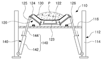
도 3은 본 발명의 일 실시예에 따른 벨트컨베이어 장치의 정면도이고, 도 4는 본 발명의 일 실시예에 따른 벨트컨베이어 장치를 작동시킨 상태의 정면도이다.3 is a front view of the belt conveyor apparatus according to an embodiment of the present invention, Figure 4 is a front view of a state in which the belt conveyor device according to an embodiment of the present invention operated.
도 3과 도 4를 참고하면, 본 실시예에 따른 벨트컨베이어 장치(110)는 이송물의 이송선상을 따라 스탠드(112)가 설치될 수 있다.3 and 4, in the
스탠드(112)는 한 쌍으로 이루어질 수 있다. 일례로, 스탠드(112)는 이송물의 이동선상에 설치되는 한 쌍의 기둥부재(114)와, 이 한 쌍의 기둥부재(114) 사이에 설치되는 지지부재(116)를 포함할 수 있다.The
지지부재(114)의 상부에는 이송물을 이송하기 위한 벨트(130)를 지지하는 캐리지 롤러(120)가 설치될 수 있다.
본 실시예에서 캐리지 롤러(120)는 중앙부에 수평으로 설치되는 수평 캐리지 롤러(122)와, 이 수평 캐리지 롤러(122)의 양측으로 설치되는 경사 캐리지 롤러(124)를 포함할 수 있다.In this embodiment, the
이러한 캐리지 롤러(120)는 지지부재(116)의 상부에 중앙 브래킷(123)이 설치될 수 있다. 또한, 이 중앙 브래킷(123)에는 수평 캐리지 롤러(122)의 회전축이 설치되어 회전에 의해 운송물이 적재된 벨트(130)를 이송할 수 있다.The
또한, 중앙 브래킷(123)의 양측에는 한 쌍의 경사 캐리지 롤러(124)가 설치될 수 있다.In addition, a pair of
이 한 쌍의 경사 캐리지 롤러(124)는 운송물의 이송선상을 향해 회전 가능하게 설치될 수 있다.The pair of
일례로, 한 쌍의 경사 캐리지 롤러(124)의 회전축은 경사 브래킷(125)에 설치되어, 운송물이 적재된 벨트의 측면부를 이동시킬 수 있다.In one example, the rotating shaft of the pair of
한편, 경사 브래킷(125)는 중앙 브래킷(123)에 인접하는 일측이 운송물의 이송방향과 평행한 축방향으로 회전 가능하게 설치될 수 있으며, 이에 따라 경사 캐리지 롤러(124)가 수평 캐리지 롤러(124)의 양측에서 가운데 방향을 향해 오므려지거나 벌려지는 방향으로 회전할 수 있다.On the other hand, the
이러한 캐리지 롤러(120)는 이송물의 운송시 수평 캐리지 롤러(122) 및 경사 캐리지 롤러(124)에 의해 벨트(130)의 중앙부를 오목하게 모아 이송물을 이송시킬 수 있다.The
이를 위해 경사 브래킷(125)은 일측이 중앙 브래킷(123)의 양측에 힌지 등에 의해 각각 회전 가능하게 설치될 수 있으며, 경사 브래킷(125)의 일측이 중앙 브래킷(123)과 근접하게 설치되는 별도의 브래킷에 회전 가능하게 설치되는 것도 가능하다.To this end, the
또한, 경사 브래킷(125)의 타측에는 경사 캐리지 롤러(124)를 수평 또는 경사지도록 회전시키는 구동부(140)가 각각 설치될 수 있다.In addition, the other side of the
본 실시예에서 구동부(140)는 스탠드(112), 일례로 기둥부재(114) 또는 작업면에 설치될 수 있다.In this embodiment, the
여기서, 구동부(140)는 일단이 경사 브래킷(125)의 타측에 신축 가능하게 연결된 작동로드(144)를 갖는 승강부(142)를 포함할 수 있다.Here, the
여기서, 승강부(142)는 복수개로 설치될 수 있으며, 일측이 기둥부재(114) 또는 작업면에 회전 가능하게 설치될 수 있고, 작동로드(144)에는 경사 브래킷(125)의 타측이 회전 가능하도록 설치될 수 있다.Here, the
이러한 승강부(142)는 작동로드(144)를 인출시킴에 따라 경사 캐리지 롤러(124)가 경사 브래킷(125)를 매개로 수평 또는 경사지게 배치될 수 있다.As the
승강부(142)는 유체, 일례로 유압에 의해 작동하는 유압 실린더를 포함할 수 있으며, 유압 외에도 전기 등을 이용하여 작동로드(144)를 인출시킬 수 있도록 제공되는 것도 가능하다.The
이러한 벨트컨베이어 장치는 연료 또는 원료 등의 이송물을 이송하는 과정에서 철편(P) 등의 이물질이 검출되어 작동이 중지되면, 승강부(142)의 작동로드(144)를 수축시킨다.When the belt conveyor device detects foreign matters such as iron pieces P in the process of transferring a feed such as fuel or raw material and stops operation, the belt conveyor device contracts the
그리고, 승강부(142)는 작동로드(144)가 수축함에 따라 이와 연결된 경사 브래킷(125)을 매개로 경사 캐리지 롤러(124)를 회전시키게 되며, 이에 따라 경사 캐리지 롤러(124)가 수평 상태로 펼쳐질 수 있다.In addition, the
이와 같이 경사 캐리지 롤러(124)가 수평 상태로 펼쳐지면, 그 상부에 위치된 벨트(130)가 펼쳐지며 중앙부에 모여 있던 이송물들이 벨트(130)의 주변부로 펼쳐질 수 있다. 그리고, 이송물들이 벨트(130)의 주변부로 펼쳐짐에 따라 이송물의 적재 높이가 낮아지게 되며, 이에 따라 이송물에 포함된 철편(P)이 쉽게 외부로 노출될 수 있는 환경이 마련될 수 있다.As such, when the
한편, 본 실시예에서 스탠드(112)의 지지부재(114)에는 경사 캐리지 롤러(124)가 수평으로 펼쳐질 경우, 경사 브래킷(125)의 하부를 지지하기 위한 받침부(126)가 설치될 수 있다. 일례로, 받침부(126)는 탄성부재를 포함할 수 있으며, 이에 따라 경사 캐리지 롤러(126)가 펼치지는 과정에서 발생하는 충격을 흡수할 수 있다.On the other hand, in the present embodiment, when the
본 발명의 실시예에서 구동부(140)는 승강부(142)가 작동로드(144)를 인출함에 따라 경사 캐리지 롤러(124)의 회전이 직접 조절되도록 구성되어 있으나, 이에 한정되지 않으며 다양한 형태로 변형될 수 있다.In the embodiment of the present invention, the driving
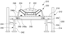
도 5는 본 발명의 다른 실시예에 따른 벨트컨베이어 장치의 정면도이고, 도 6은 본 발명의 다른 실시예에 따른 벨트컨베이어 장치를 작동시킨 상태의 정면도이다.5 is a front view of the belt conveyor apparatus according to another embodiment of the present invention, Figure 6 is a front view of a state in which the belt conveyor apparatus according to another embodiment of the present invention operated.
일례로, 도 5와 도 6을 참고하면, 벨트컨베이어 장치(210)는, 기둥부재(214)와, 지지부재(216)를 갖는 스탠드(212)를 포함하고, 이 스탠드(212)에는 캐리지 롤러(220)가 설치될 수 있다. 캐리지 롤러(220)는 지지부재(216)의 중앙부에 설치되는 수평 캐리지 롤러(222) 및 이 수평 캐리지 롤러(222)의 양측에 일측을 축으로 회전 가능하게 설치된 경사 캐리지 롤러(224)를 포함할 수 있다.For example, referring to FIGS. 5 and 6, the
또한, 본 실시예에서 벨트컨베이어 장치(210)는 경사 캐리지 롤러(224)의 타측을 수평 또는 경사지도록 회전시키는 구동부(240)가 각각 설치될 수 있다.In addition, in the present embodiment, the
여기서, 구동부(240)는 스탠드(112) 또는 작업면에 설치되며, 일단이 경사 캐리지 롤러(224)에 연결되는 작동로드(244) 및 이 작동로드(244)를 승강시키는 승강부(242)를 포함할 수 있다.Here, the driving
또한, 승강부(242)의 작동로드(244)에는 프레임(246)이 설치될 수 있다. 그리고, 작동로드(244)가 상, 하로 인출됨에 따라 작동로드(244)에 연결된 프레임(246)이 상, 하로 이동할 수 있다.In addition, the
또한, 경사 캐리지 롤러(124)와 프레임(246) 사이에는 프레임(246)의 승강에 연동하여 경사 캐리지 롤러(224)를 회전시키기 위한 연결암(248)이 설치될 수 있다.In addition, a
여기서, 연결암(248)은 일측이 경사 캐리지 롤러(224)의 타측에 각각 회전 가능하게 설치될 수 있다. 그리고, 연결암(248)의 타측은 프레임에 연결되어 프레임(246)의 승강에 연동하여 경사 캐리지 롤러(224)를 회전시킬 수 있다.Here, the
이를 위해 프레임(246)에는 연결암(248)의 타단을 이동 가능하게 지지하는 브래킷(249)이 설치될 수 있다. 또한, 연결암(248)의 타측에는 브래킷(249)에 안내되어 회전하는 바퀴(248a)가 구비될 수 있다. 더불어, 브래킷(249)에는 연결암의 바퀴(248a)를 안내하기 위한 홈(249a)이 형성될 수 있다.To this end, the
또한, 구동부(240)는 프레임(246)의 위치를 감지하기 위한 위치감지센서(250)를 더 포함할 수 있다. 이 위치감지센서(250)는 (도시되지 않은) 제어부와 연결되어 위치감지센서(250)에 의해 감지된 프레임(246)의 위치에 따라 승강부(240)의 상승 또는 하강을 제어할 수 있다.In addition, the driving
일례로 위치감지센서(250)는 스탠드의 기둥부재에 설치되는 리미트 센서(252, 254)를 포함할 수 있다. 이 리미트 센서(252, 254)는 프레임(246)의 상한 및 하한 위치에 각각 설치될 수 있으며, 프레임(246)의 접촉에 의해 상한 또는 하한의 감지신호를 발생할 수 있다.For example, the
이러한 위치감지센서(250)로는 접촉식 리미트 센서 외에도 자기식 또는 광학식 감지센서가 적용되는 것도 가능하다.
The
본 실시예에서 연결암(248)은 브래킷(249)에 안내되어 이동하는 것으로 개시되어 있으나, 이에 한정되지 않으며 다양하게 변형될 수 있다.In the present embodiment, the
일례로, 연결암(248)은 일단부가 경사 캐리지 롤러(124)의 타측에 고정될 수 있으며, 타단부가 프레임(246)에 지지되도록 제공될 수 있다. 이때, 연결암(248)의 타단부에는 프레임(246)을 따라 이동할 수 있도록 바퀴가 구비될 수 있다. 한편, 본 실시예에서 연결암은 프레임에 설치되어 경사 캐리지 롤러의 하부를 지지하도록 제공되는 것도 가능하다.
For example, one end of the
더불어, 본 실시예에서 벨트컨베이어의 이물질 제거장치는 수평 캐리지 롤러의 양측에 설치된 경사 캐리지 롤러가 회전하여 수평으로 펼쳐지도록 구성된 실시예에 대해 설명하고 있으나, 이에 한정되지 않으며 수평 캐리지 롤러가 승강부에 의해 승강하도록 설치될 수 있다.In addition, the foreign material removal apparatus of the belt conveyor in the present embodiment has been described with respect to the embodiment configured to rotate the inclined carriage rollers installed on both sides of the horizontal carriage roller to spread out horizontally, but is not limited to this, the horizontal carriage roller is in the lifting unit It can be installed to lift up and down by.
또한, 경사 캐리지 롤러는 일측을 축으로 수평 캐리지 롤러와 회전 가능하게 결합될 수 있으며, 타측은 스탠드에 회전 가능하게 설치될 수 있다. 따라서, 경사 캐리지 롤러는 수평 캐리지 롤러가 승강부에 의해 승강에 연동하여 타측을 축으로 회전하며 수평 캐리지 롤러에 수평으로 배치될 수 있다.
In addition, the inclined carriage roller may be rotatably coupled with the horizontal carriage roller around one side, the other side may be rotatably installed on the stand. Therefore, the inclined carriage roller may be disposed horizontally on the horizontal carriage roller while the horizontal carriage roller is rotated about the other side in the axis in conjunction with the lifting by the lifting unit.
본 발명은 상술한 실시형태 및 첨부된 도면에 의해 한정되지 아니하며, 청구범위에 기재된 본 발명의 기술적 사상을 벗어나지 않는 범위 내에서 다양한 형태의 치환, 변형 및 변경이 가능하다는 것은 당 기술분야의 통상의 지식을 가진 자에게 자명할 것이다.
The present invention is not limited to the above-described embodiment and the accompanying drawings, and it is possible to substitute, modify, and change various forms within the scope of the technical spirit of the present invention described in the claims. It will be self-evident to those who have knowledge.
110 : 벨트컨베이어 장치 112 : 스탠드
114 : 기둥부재 116 : 지지부재
120 : 캐리지 롤러 122 : 수평 캐리지 롤러
123 : 중앙 브래킷 124 : 경사 캐리지 롤러
125 : 경사 브래킷 130 : 벨트
140 : 구동부 142 : 승강부
144 : 작동로드110: belt conveyor device 112: stand
114: pillar member 116: support member
120: carriage roller 122: horizontal carriage roller
123: center bracket 124: inclined carriage roller
125: inclination bracket 130: belt
140: driving unit 142: lifting unit
144: working rod
Claims (6)
상기 스탠드의 상부에 설치된 수평 캐리지 롤러;
상기 수평 캐리지 롤러의 좌, 우측에 일측을 축으로 회전 가능하게 설치된 한 쌍의 경사 캐리지 롤러; 및
상기 경사 캐리지 롤러의 타측에 각각 설치되어 상기 경사 캐리지 롤러를 수평 또는 경사지도록 회전시키는 구동부;
를 포함하는 벨트컨베이어.
A stand installed on the feed line of the conveyed material;
A horizontal carriage roller installed on the top of the stand;
A pair of inclined carriage rollers rotatably installed at one side on the left and right sides of the horizontal carriage roller; And
A driving unit installed at the other side of the inclined carriage roller to rotate the inclined carriage roller horizontally or inclined;
Belt conveyor comprising a.
상기 구동부는 상기 스탠드 또는 작업면에 설치되며 일단이 상기 경사 캐리지 롤러의 타측에 연결되어 신축되는 작동로드를 갖는 승강부를 포함하는 것을 특징으로 하는 벨트컨베이어.
The method according to claim 1,
The driving unit is installed on the stand or the working surface belt conveyor, characterized in that it comprises a lifting unit having one end is connected to the other side of the inclined carriage roller stretched.
상기 스탠드 또는 작업면에 설치되며 신축되는 작동로드를 갖는 승강부와,
상기 승강부의 작동로드에 의해 상, 하로 이동하는 프레임과,
상기 경사 캐리지 롤러와 상기 프레임 사이에 설치되어 상기 프레임에 연동하여 상기 경사 캐리지 롤러를 회전시키는 연결암을 포함하는 것을 특징으로 하는 벨트컨베이어.
The method of claim 1, wherein the driving unit
An elevating part installed on the stand or the working surface and having an elastic rod;
A frame moving up and down by an operation rod of the lifting unit;
And a connecting arm installed between the inclined carriage roller and the frame to rotate the inclined carriage roller in association with the frame.
상기 연결암은 일단부가 상기 캐리지 롤러의 타측에 회전 가능하게 설치되고,
상기 프레임은 상기 연결암의 타단부를 회전 내지 이동 가능하게 지지하는 브래킷을 포함하는 것을 특징으로 하는 벨트컨베이어.
The method according to claim 2,
One end of the connection arm is rotatably installed on the other side of the carriage roller,
The frame conveyor comprises a bracket for supporting the other end of the connection arm to be rotatable or movable.
상기 위치감지센서에 의해 감지된 상기 프레임의 위치에 따라 상기 승강부의 작동을 제어하는 제어부를 포함하는 것을 특징으로 하는 벨트컨베이어.
The apparatus of claim 2, wherein the driving unit comprises: a position sensor for detecting an upper limit or a lower limit of the frame;
And a control unit for controlling the operation of the lifting unit in accordance with the position of the frame detected by the position detecting sensor.
상기 스탠드에 설치되어 상기 경사 캐리지 롤러의 하부를 지지하는 받침부를 더 포함하는 것을 특징으로 하는 벨트컨베이어.The method according to any one of claims 1 to 5,
The belt conveyor further comprises a support portion installed on the stand for supporting the lower portion of the inclined carriage roller.
Priority Applications (1)
| Application Number | Priority Date | Filing Date | Title |
|---|---|---|---|
| KR1020100134247A KR101253876B1 (en) | 2010-12-24 | 2010-12-24 | Belt conveyor |
Applications Claiming Priority (1)
| Application Number | Priority Date | Filing Date | Title |
|---|---|---|---|
| KR1020100134247A KR101253876B1 (en) | 2010-12-24 | 2010-12-24 | Belt conveyor |
Publications (2)
| Publication Number | Publication Date |
|---|---|
| KR20120072479A true KR20120072479A (en) | 2012-07-04 |
| KR101253876B1 KR101253876B1 (en) | 2013-04-16 |
Family
ID=46707154
Family Applications (1)
| Application Number | Title | Priority Date | Filing Date |
|---|---|---|---|
| KR1020100134247A KR101253876B1 (en) | 2010-12-24 | 2010-12-24 | Belt conveyor |
Country Status (1)
| Country | Link |
|---|---|
| KR (1) | KR101253876B1 (en) |
Cited By (4)
| Publication number | Priority date | Publication date | Assignee | Title |
|---|---|---|---|---|
| CN103332445A (en) * | 2013-07-02 | 2013-10-02 | 无锡天惠塑机有限公司 | Corn conveyer with convenient-to-disassemble structure |
| KR101503379B1 (en) * | 2013-10-30 | 2015-03-24 | 한국타이어 주식회사 | Block rubber feeding apparatus of tire mixing process |
| WO2016094033A1 (en) * | 2014-12-09 | 2016-06-16 | Laitram, L.L.C. | Flexible-belt conveyor and methods of conveying |
| CN108438749A (en) * | 2018-04-11 | 2018-08-24 | 安徽攀登重工股份有限公司 | The anti-pipe-expanding device of pipe conveyer |
Family Cites Families (1)
| Publication number | Priority date | Publication date | Assignee | Title |
|---|---|---|---|---|
| JP2752579B2 (en) * | 1994-04-01 | 1998-05-18 | 川崎製鉄株式会社 | Belt conveyor transfer section support device |
-
2010
- 2010-12-24 KR KR1020100134247A patent/KR101253876B1/en active IP Right Grant
Cited By (5)
| Publication number | Priority date | Publication date | Assignee | Title |
|---|---|---|---|---|
| CN103332445A (en) * | 2013-07-02 | 2013-10-02 | 无锡天惠塑机有限公司 | Corn conveyer with convenient-to-disassemble structure |
| KR101503379B1 (en) * | 2013-10-30 | 2015-03-24 | 한국타이어 주식회사 | Block rubber feeding apparatus of tire mixing process |
| WO2016094033A1 (en) * | 2014-12-09 | 2016-06-16 | Laitram, L.L.C. | Flexible-belt conveyor and methods of conveying |
| US10118765B2 (en) | 2014-12-09 | 2018-11-06 | Laitram, L.L.C. | Flexible-belt conveyor and methods of conveying |
| CN108438749A (en) * | 2018-04-11 | 2018-08-24 | 安徽攀登重工股份有限公司 | The anti-pipe-expanding device of pipe conveyer |
Also Published As
| Publication number | Publication date |
|---|---|
| KR101253876B1 (en) | 2013-04-16 |
Similar Documents
| Publication | Publication Date | Title |
|---|---|---|
| KR101767868B1 (en) | Automatic feeder for metal bar | |
| CN207724522U (en) | Composite board autosizing and veneering production line | |
| KR101253876B1 (en) | Belt conveyor | |
| CN207346722U (en) | A kind of transfer device of doing over again of wall-hung boiler production line | |
| KR100785285B1 (en) | Device for adjusting edge position of coil | |
| CN212531447U (en) | Automatic change panel pile up neatly device | |
| CN109382329B (en) | Square plate size and weight detection device and using method thereof | |
| CN206257975U (en) | Billet heating furnace feeding device | |
| CN112027658A (en) | Feeding equipment, feeding method and electronic product part detection system | |
| CN112846415A (en) | Single-machine truss integrated stacker | |
| CN114042646A (en) | Brake disc size detection equipment | |
| JP4825080B2 (en) | Pallet centrifugal dehydrator | |
| KR101711006B1 (en) | Coal yard arrangement device for truck transport | |
| CN112027681A (en) | Automatic change panel pile up neatly device | |
| JP4781936B2 (en) | Pallet centrifugal dehydrator | |
| JP5184871B2 (en) | Article conveying device | |
| KR101225731B1 (en) | Sensing device of belt conveyor | |
| JP2006027753A (en) | Turntable device for motor inspection and repair line | |
| KR101344317B1 (en) | Continuous ship unloader | |
| KR101294916B1 (en) | Materials treatment apparatus | |
| KR100931240B1 (en) | Belt conveyor conveying roll damage detection and roll separating device | |
| CN206735381U (en) | Packed class material de-stacking system | |
| JP6285770B2 (en) | Work transfer device and processing line | |
| CN104972308A (en) | Automatic production line for metal plate pulley | |
| KR20120110317A (en) | Sensing device for damage of belt conveyor |
Legal Events
| Date | Code | Title | Description |
|---|---|---|---|
| A201 | Request for examination | ||
| E902 | Notification of reason for refusal | ||
| E90F | Notification of reason for final refusal | ||
| E701 | Decision to grant or registration of patent right | ||
| GRNT | Written decision to grant | ||
| FPAY | Annual fee payment |
Payment date: 20160405 Year of fee payment: 4 |
|
| FPAY | Annual fee payment |
Payment date: 20180405 Year of fee payment: 6 |
|
| FPAY | Annual fee payment |
Payment date: 20190403 Year of fee payment: 7 |