KR20120056801A - Spiral spring - Google Patents
Spiral spring Download PDFInfo
- Publication number
- KR20120056801A KR20120056801A KR1020117030385A KR20117030385A KR20120056801A KR 20120056801 A KR20120056801 A KR 20120056801A KR 1020117030385 A KR1020117030385 A KR 1020117030385A KR 20117030385 A KR20117030385 A KR 20117030385A KR 20120056801 A KR20120056801 A KR 20120056801A
- Authority
- KR
- South Korea
- Prior art keywords
- spiral spring
- frame
- spiral
- plates
- plate
- Prior art date
Links
Images


Classifications
-
- G—PHYSICS
- G04—HOROLOGY
- G04B—MECHANICALLY-DRIVEN CLOCKS OR WATCHES; MECHANICAL PARTS OF CLOCKS OR WATCHES IN GENERAL; TIME PIECES USING THE POSITION OF THE SUN, MOON OR STARS
- G04B17/00—Mechanisms for stabilising frequency
- G04B17/04—Oscillators acting by spring tension
- G04B17/06—Oscillators with hairsprings, e.g. balance
- G04B17/063—Balance construction
-
- G—PHYSICS
- G04—HOROLOGY
- G04B—MECHANICALLY-DRIVEN CLOCKS OR WATCHES; MECHANICAL PARTS OF CLOCKS OR WATCHES IN GENERAL; TIME PIECES USING THE POSITION OF THE SUN, MOON OR STARS
- G04B17/00—Mechanisms for stabilising frequency
- G04B17/30—Rotating governors, e.g. centrifugal governors, fan governors
-
- F—MECHANICAL ENGINEERING; LIGHTING; HEATING; WEAPONS; BLASTING
- F16—ENGINEERING ELEMENTS AND UNITS; GENERAL MEASURES FOR PRODUCING AND MAINTAINING EFFECTIVE FUNCTIONING OF MACHINES OR INSTALLATIONS; THERMAL INSULATION IN GENERAL
- F16F—SPRINGS; SHOCK-ABSORBERS; MEANS FOR DAMPING VIBRATION
- F16F1/00—Springs
- F16F1/02—Springs made of steel or other material having low internal friction; Wound, torsion, leaf, cup, ring or the like springs, the material of the spring not being relevant
- F16F1/04—Wound springs
- F16F1/10—Spiral springs with turns lying substantially in plane surfaces
-
- G—PHYSICS
- G04—HOROLOGY
- G04B—MECHANICALLY-DRIVEN CLOCKS OR WATCHES; MECHANICAL PARTS OF CLOCKS OR WATCHES IN GENERAL; TIME PIECES USING THE POSITION OF THE SUN, MOON OR STARS
- G04B17/00—Mechanisms for stabilising frequency
- G04B17/04—Oscillators acting by spring tension
- G04B17/06—Oscillators with hairsprings, e.g. balance
- G04B17/066—Manufacture of the spiral spring
-
- G—PHYSICS
- G04—HOROLOGY
- G04B—MECHANICALLY-DRIVEN CLOCKS OR WATCHES; MECHANICAL PARTS OF CLOCKS OR WATCHES IN GENERAL; TIME PIECES USING THE POSITION OF THE SUN, MOON OR STARS
- G04B17/00—Mechanisms for stabilising frequency
- G04B17/32—Component parts or constructional details, e.g. collet, stud, virole or piton
- G04B17/325—Component parts or constructional details, e.g. collet, stud, virole or piton for fastening the hairspring in a fixed position, e.g. using a block
-
- G—PHYSICS
- G04—HOROLOGY
- G04B—MECHANICALLY-DRIVEN CLOCKS OR WATCHES; MECHANICAL PARTS OF CLOCKS OR WATCHES IN GENERAL; TIME PIECES USING THE POSITION OF THE SUN, MOON OR STARS
- G04B17/00—Mechanisms for stabilising frequency
- G04B17/32—Component parts or constructional details, e.g. collet, stud, virole or piton
- G04B17/34—Component parts or constructional details, e.g. collet, stud, virole or piton for fastening the hairspring onto the balance
- G04B17/345—Details of the spiral roll
-
- F—MECHANICAL ENGINEERING; LIGHTING; HEATING; WEAPONS; BLASTING
- F16—ENGINEERING ELEMENTS AND UNITS; GENERAL MEASURES FOR PRODUCING AND MAINTAINING EFFECTIVE FUNCTIONING OF MACHINES OR INSTALLATIONS; THERMAL INSULATION IN GENERAL
- F16F—SPRINGS; SHOCK-ABSORBERS; MEANS FOR DAMPING VIBRATION
- F16F2226/00—Manufacturing; Treatments
Abstract
본 발명은 시계 무브먼트에 대한 스파이럴 스프링 (10)에 관한 것이며, 상기 스파이럴 스프링은 서로 감긴 동일면의 판들 (10a, 10b)을 포함한다. 또한 각각의 판의 내단들은 단일 콜릿 (12)에 고정된다. 판들 (10a, 10b) 및 콜릿 (12)은 단일 부품으로 제조된다.The present invention relates to a spiral spring 10 for a watch movement, which comprises coplanar plates 10a, 10b wound together. Also the inner ends of each plate are fixed to a single collet 12. The plates 10a, 10b and the collet 12 are made of a single part.
Description
본 발명은 기계식 시계 제작 분야에 관한 것이다. 더욱 상세하게는, 기계식 시계의 조속기 (regulator organ)에 구비되는 스파이럴 스프링에 관한 것이다.The present invention relates to the field of mechanical watches. More specifically, it relates to a spiral spring provided in the regulator organ of a mechanical watch.
벽시계, 추, 및 기계식 또는 전자식 시계에서, 명칭 그대로 시계 작동을 조절하는 조절기가 존재한다. 기계식 시계의 경우, 조속기는 밸런스 및 스파이럴 스프링으로 형성된다.In wall clocks, weights, and mechanical or electronic clocks, controllers, as the name suggests, control clock operation. In the case of a mechanical watch, the governor is formed by a balance and a spiral spring.
전통적으로, 스파이럴은 일반적으로 아르키메데스의 나선으로 자체가 감긴 직각 단면의 금속 판 (leaf)이다. 이것은 중심이 콜릿이라는 부품에 의해 밸런스-스태프 (balance-staff)에 고정된다. 스파이럴 외부는 밸런스-스프링 스터드 (stud)라는 부품에 의해 밸런스-콕이라는 부르는 밸런스에 고정된다. 밸런스-스프링 스터드는 직접 또는 이동식 밸런스-스프링 스터드 지지체를 통하여 밸런스-콕에 고정된다.Traditionally, spirals are usually metal leaves of right-angled cross sections, wound by themselves with Archimedes spirals. It is centered on the balance-staff by a part called the collet. The spiral exterior is fixed to a balance called a balance-cock by a component called a balance-spring stud. The balance-spring studs are fixed to the balance-cock directly or via a movable balance-spring stud support.
이러한 스파이럴 조립체는 시계의 등시성 (isochronism)에 대하여 최적이 아니다. 사실, 스파이럴 중심은 진행되는 동안 이동되어, 밸런스-스태프 축에 작용 힘을 유발시킨다. 축에 인가되는 힘은 등시성에 상당히 영향을 미치는 것으로 관찰된다.Such spiral assemblies are not optimal for isochronism of the field of view. In fact, the spiral center is moved during the process, causing an acting force on the balance-staff axis. It is observed that the force applied to the axis significantly affects the isochronism.
서로 반대 방향으로 다른 면들에서 밸런스-스태프에 장착된 두 개의 스파이럴들을 가지는 시계들이 공지된다. 하우스 H. Moser & Cie는 서로 반대 방향으로 밸런스 각 측에 배열된 두 개의 스파이럴들을 가지는 탈진장치 (escapement)를 제공한다. EP2063325 문서는 동심적이고 동일 면에 배열된 두 개의 전통적인 스파이럴들을 가지는 기구를 제안한다. 전통적으로 제작되는 스파이럴들의 정확한 특성들은 얻는 것은 어려운 것으로 알려져 있으므로, 두 개의 스파이럴들은 약간이기는 하겠지만 아주 자주 다를 것이다.Watches are known which have two spirals mounted to the balance-staff on different sides in opposite directions. House H. Moser & Cie provides an escapement with two spirals arranged on each side of the balance in opposite directions. The EP2063325 document proposes a mechanism with two traditional spirals which are concentric and arranged in the same plane. The exact characteristics of traditionally manufactured spirals are known to be difficult to obtain, so the two spirals, albeit slightly, will be quite different.
따라서 이러한 다른 특성들을 가지는 두 개의 스파이럴들로 제공되는 밸런스를 조정하고, 두 개의 스파이럴들에 의해 부여되는 힘들을 정렬하는 것은 어려운 일이다. 또한, 두 개의 스파이럴들 간 잠재적인 차이로 대부분의 경우 밸런스-스태프에 부가되는 힘들 결과는 비-영점화 (non-null)되어 제어가 어려울 것이다.Therefore, it is difficult to adjust the balance provided by two spirals having these different characteristics, and to align the forces exerted by the two spirals. Also, due to the potential difference between the two spirals, in most cases the force consequences added to the balance-staff will be non-null and difficult to control.
따라서 본 발명은 구현이 간단하면서도 시계의 등시성 개선을 가능하게 하는 스파이럴을 제안하는 것이다.Therefore, the present invention proposes a spiral that enables simple isochronization and isochronous improvement.
더욱 상세하게는, 본 발명은 제1항에 정의된 시계 무브먼트 (movement)의 스파이럴 스프링에 관한 것이다.More particularly, the invention relates to a spiral spring of a watch movement defined in claim 1.
본 발명의 다른 특징부들은 종속항들에서 제공된다.Other features of the invention are provided in the dependent claims.
본 발명의 다른 특징부들은 본 발명의 실시예들의 평면 개략도인 도 1 내지 도 6을 참고하여 하기 설명을 독해하면 더욱 명백하여 질 것이다.Other features of the present invention will become more apparent upon reading the following description with reference to FIGS. 1 to 6, which are plan schematic diagrams of embodiments of the present invention.
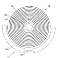
도 1은 판형 스파이럴 스프링 (10)을 도시한 것이다. 콜릿 (12)에 연결된 제1 내단 (inner end)을 포함한다. 1 shows a
본 발명에 특정하게, 콜릿 (12)에서, 여러 판들 (leaves)이 전개되고, 도면에서는 2개를 도시한다. 따라서, 제1 판 (10a) 및 제2 판 (10b)이 동일 면 및 동일 방향으로 권취된다. 판들 (10a, 10b)은 상호 권취되고, 하나의 코일들은 다른 코일들 사이에 삽입된다. 제1 판 (10a) 및 제2판 (10b)은 서로에 대하여 180°로 배열된다. 판들은 동일하고, 따라서 판들의 단들은 원에 놓이고 서로에 대하여 180°에 놓인다.In particular to the present invention, in the
바람직하게는, 판들의 외단들은 강성의 프레임 (14)으로 서로 연결되고, 즉 프레임은 스프링에 의한 탄성 토크에 (실제로) 기여하지 않는다. 프레임 (14) 형상은 스파이럴 중심에 대하여 원형 대칭적이다. 바람직하게는, 프레임은 스파이럴과 동심으로 원형 경로를 따른다.Preferably, the outer ends of the plates are connected to each other with a
전형적으로, 실리콘-유형의 재료로 형성되면, 콜릿 (12)은 스파이럴 나머지와 일 부품으로 제조된다. 바람직하게는, 판들이 동일한 탄성 특성을 가지기 위하여, 두 판들 (10a, 10b), 콜릿 (12) 및 프레임 (14)는 단일 부품으로 일체로 (monolithically) 제조된다. 이를 위하여, 본 발명에 의한 스파이럴은 디프 식각 기술 (deep etching technique)로 형상화될 수 있는 재료들로 제조될 수 있고, 특히 실리카 층에 의해 잠재적으로 덮인 단결정성 실리콘으로 제조되는 특히 실리콘-기반 스파이럴들뿐 아니라 성장 이후 디프 식각으로 획득되는 다이아몬드로 제조되는 스파이럴들, 또는 DCS (다이아몬드 코팅된 실리콘)에서 제조되는 스파이럴들 즉 다이아몬드로 덮인 실리콘 스파이럴들이다.Typically, formed from a silicon-type material, the
두 개의 동일한 판들 (10a, 10b)의 대칭적 배열로 인하여, 판들 각각은 다른 판에 의해 부가되는 힘을 상쇄시키는 힘을 밸런스-스태프에 부가한다. 따라서, 스태프에 대한 작용들은 최소화, 또는 실제로 영점화되고, 이로써 발진기의 등시성이 개선될 수 있다. Due to the symmetrical arrangement of the two
프레임 (14)는 부착기 (attachment organ), 바람직하게는 밸런스-스프링 스터드를 지지할 수 있도록 구성되어 스파이럴을 무브먼트에 고정된 밸런스-스프링 스터드에 연결시킨다. 도 1에서, 프레임은 본 분야의 숙련가에게 공지된 슬롯형 밸런스-스프링 스터드를 수용할 수 있는 폭이 있는 부분을 가진다. 더욱 상세하게, 프레임은 밸런스-스프링 스터드를 수용하는 넓은 구역 (14a) 및 좁은 구역 (14b)을 가진다. 스터드는 프레임에 적합한 기법, 예를들면 본 분야의 숙련가에 의해 선택되는 접착 또는 용접으로 고정된다.The
도 3에서, 프레임 (14)은 여러 좁은 구역들 (14b)을 가지고, 이는 밸런스-스프링 스터드를 프레임 주위 여러 지점들에 배치할 수 있고, 무브먼트 제조 융통성을 제공한다.In FIG. 3, the
도 4는 비-슬롯형 밸런스-스프링 스터드를 수용하는 홀 (16)이 제공되는 프레임을 제안한다. 도 5의 프레임 (14)은 동일 방식으로 구성되나, 판들 외단들을 두 측들로 연결하여 완전한 원을 만든다. 따라서 중량 분산이 대칭적이다. 홀이 제공되는 프레임 구성에서도, 프레임은 중공일 수 있다는 것을 이해하여야 한다. 또한 여러 홀들이 프레임에 배열될 수 있다.4 proposes a frame in which a
또한 프레임 기능은 판들의 단들을 고정시킬 수 있는 여러 밸런스-스프링 스터드들 (판 당 하나의 밸런스-스프링 스터드)을 포함하는 밸런스-콕에 의해 수행될 수 있다는 것을 이해하여야 한다. 이러한 경우, 프레임은 생략되고 콜릿 및 판들만이 일체화된다. It should also be understood that the frame function may be performed by a balance-cock that includes several balance-spring studs (one balance-spring stud per plate) that may hold the ends of the plates. In this case, the frame is omitted and only the collet and the plates are integrated.
도면들에서 두 개의 판들을 포함하는 스파이럴 스프링 (10)이 도시되지만, 더 이상이 제공될 수 있다. 따라서 콜릿 주위로 360°/n로 분포되고, 외단들 역시360°/n로 분포되는 n 개의 동일한 판들을 가지는 것이 가능하다. 이러한 배열로 판들 및 밸런스-스태프 주위 힘들 분산이 개선되고 따라서 양호한 상쇄가 가능하다.In the figures a
n 개의 판들을 가지는 경우, 프레임 (14)는 360°/n 또는 본 분야의 숙련가에 의해 선택되는 이 값의 배수의 원호 형상을 형성한다. 또한 완전한 원형 프레임도 가능하다.In the case of n plates, the
각각의 판은 다른 판들의 코일들 사이로 감기므로, 주어진 치수의 스파이럴에 대하여, 판들 개수가 증가하면, 한편으로, 각각의 판의 활동 길이 (active length)가 줄어든다는 것을 이해할 수 있다. 따라서, 두께 e (두께는 스파이럴 면에서 판의 치수이다), 코일들 사이 피치가 p, 표면적 S를 차지하는 단일 판으로 제공되는 활동 길이가 L인 종래 스파이럴에 대하여, 두께 e, 각 코일에 대한 피치 p, 동일 표면 S를 차지하는 n 개의 판들의 본 발명에 의한 스파이럴에서, 각 판은 활동 길이가 L/n일 것이다. 이것은 결과적으로 판의 강성을 높이지만, 이것은 각각의 판 두께를 줄여서 상쇄될 수 있고, 이는 활동 길이를 늘리고 강성을 높이는 것을 가능하게 한다. 따라서 종래 스파이럴 스프링들로 얻는 토크들에 대응되는 전체 소망 토크를 얻는 것이 용이하다. 또한 원하는 길이를 가지는 판들을 얻기 위하여 더 큰 표면적을 차지하는 스파이럴들을 고려할 수 있다. 실제 관점에서, 2, 3 또는 4 개의 판들을 가지는 스파이럴들이 바람직하다.Since each plate is wound between the coils of the other plates, it can be understood that for spirals of a given dimension, as the number of plates increases, on the one hand, the active length of each plate decreases. Thus, for a conventional spiral whose thickness e (thickness is the dimension of the plate in the spiral plane), the pitch between the coils is p, and the active length L is provided as a single plate occupying surface area S, the thickness e, the pitch for each coil p, in the spiral according to the invention of n plates occupying the same surface S, each plate will have an L / n length of action. This in turn increases the stiffness of the plate, but this can be counteracted by reducing the thickness of each plate, which makes it possible to increase the length of action and increase the stiffness. Therefore, it is easy to obtain the total desired torque corresponding to the torques obtained with conventional spiral springs. It is also possible to consider spirals occupying a larger surface area to obtain plates with the desired length. In practical terms, spirals having two, three or four plates are preferred.
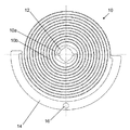
도 6은 각 판의 외부 코일에 스파이럴 중심을 보정하고 작용 부분의 무게중심을 탄성 토크의 작용 중심 즉 스파이럴 중심으로 전달할 수 있는 보강구 (18) 가 제공되는 스파이럴 스프링 (10)을 제안한다. 이러한 보강구 (18)는 스파이럴 전개 동심도 (concentricity)를 개선하고 축에 대한 작용을 더욱 줄일 수 있다. 보강구 (18) 자체는 스파이럴의 탄성 토크 형성에 관여하지 않는다는 것을 이해하여야 한다. 도 6에 도시된 바와 같이, 마지막 나선 둘레 (spire)를 분리하는 피치는 끝에서 두 번째 코일로부터 일정 거리에 있고 보강구를 포함한다. 또한 마지막 코일 및 끝에서 두 번째 코일 사이 거리는 특히 보강구에서 다른 코일들을 분리하는 피치보다 더 작은 것도 고려할 수 있을 것이다.FIG. 6 proposes a
본 발명은 본 발명의 단지 비-제한적 설명으로 제공되었고 본 분야의 숙련가는 상기 제공된 설명으로부터 직접 청구범위에 따라 정의된 사상을 벗어남이 없는 여러 대안들을 제공할 수 있을 것이다. 특히 각각의 판의 피치는 도면에 도시된 바와 같이 일정할 수 있으나 가변 될 수 있다. 또한, 밸런스-스프링 스터드는 다른 고정 모드 특히 밸런스-콕으로 직접 프레임을 고정시키는 나사로 대체될 수 있다.
The present invention has been presented only as a non-limiting description of the invention and those skilled in the art will be able to provide various alternatives without departing from the spirit defined in accordance with the claims directly from the description provided above. In particular, the pitch of each plate may be constant as shown in the figure, but may vary. In addition, the balance-spring studs can be replaced with screws for fastening the frame directly with other fixing modes, in particular with the balance cock.
Claims (14)
Applications Claiming Priority (3)
| Application Number | Priority Date | Filing Date | Title |
|---|---|---|---|
| CH01385/09 | 2009-09-07 | ||
| CH01385/09A CH701783B1 (en) | 2009-09-07 | 2009-09-07 | spiral spring watch movement. |
| PCT/EP2010/061913 WO2011026725A1 (en) | 2009-09-07 | 2010-08-16 | Spiral spring |
Publications (1)
| Publication Number | Publication Date |
|---|---|
| KR20120056801A true KR20120056801A (en) | 2012-06-04 |
Family
ID=41478830
Family Applications (1)
| Application Number | Title | Priority Date | Filing Date |
|---|---|---|---|
| KR1020117030385A KR20120056801A (en) | 2009-09-07 | 2010-08-16 | Spiral spring |
Country Status (11)
| Country | Link |
|---|---|
| US (3) | US8764282B2 (en) |
| EP (1) | EP2476028B1 (en) |
| JP (1) | JP5507690B2 (en) |
| KR (1) | KR20120056801A (en) |
| CN (1) | CN102472996B (en) |
| AU (1) | AU2010291399B2 (en) |
| CH (1) | CH701783B1 (en) |
| ES (1) | ES2431071T3 (en) |
| RU (1) | RU2551478C2 (en) |
| SG (1) | SG176685A1 (en) |
| WO (1) | WO2011026725A1 (en) |
Families Citing this family (19)
| Publication number | Priority date | Publication date | Assignee | Title |
|---|---|---|---|---|
| JP5914456B2 (en) † | 2010-04-01 | 2016-05-11 | ロレックス・ソシエテ・アノニムRolex Sa | Gear fixing device |
| EP2520983A1 (en) * | 2011-05-03 | 2012-11-07 | Nivarox-FAR S.A. | Barrel comprising resilient energy accumulation means |
| US9151351B2 (en) | 2011-06-28 | 2015-10-06 | Controls International, Inc. | Adjustable fail-safe rotary spring operator with a retaining band |
| US9411314B2 (en) | 2011-09-29 | 2016-08-09 | Rolex Sa | Integral assembly of a hairspring and a collet |
| US9658598B2 (en) * | 2012-07-17 | 2017-05-23 | Master Dynamic Limited | Hairspring for a time piece and hairspring design for concentricity |
| CH707165B1 (en) * | 2012-11-07 | 2016-12-30 | Patek Philippe Sa Geneve | Watch movement with sprung balance. |
| HK1186057A2 (en) | 2013-01-14 | 2014-03-07 | Master Dynamic Ltd | Stress-relief elastic structure of hairspring collet |
| EP2884346A1 (en) * | 2013-12-16 | 2015-06-17 | ETA SA Manufacture Horlogère Suisse | Polygonal hairspring for a timepiece resonator |
| EP2916177B1 (en) * | 2014-03-05 | 2018-11-07 | Nivarox-FAR S.A. | Hairspring intended for being clamped by a spring washer |
| EP3023844B1 (en) | 2014-11-20 | 2017-06-28 | Nivarox-FAR S.A. | Flexible ferrule |
| EP3304215B1 (en) * | 2015-06-03 | 2019-03-06 | ETA SA Manufacture Horlogère Suisse | Resonator with fine tuning through index-assembly |
| EP3214506B1 (en) * | 2016-03-04 | 2019-01-30 | ETA SA Manufacture Horlogère Suisse | Compact hairspring with constant double cross-section |
| US11021238B2 (en) * | 2017-02-07 | 2021-06-01 | Parker-Hannifin Corporation | Disc spring providing linear axial motion |
| EP3418816B1 (en) * | 2017-06-20 | 2019-10-16 | Lakeview Innovation Ltd. | Balance spring with lozenge section for a mechanical clockwork of a watch and method for producing said balance spring |
| US10838366B2 (en) * | 2017-09-14 | 2020-11-17 | Timex Group Usa, Inc. | Bidirectional MEMS driving arrangements with a force absorbing system |
| EP3561606B1 (en) * | 2018-04-27 | 2022-01-26 | The Swatch Group Research and Development Ltd | Shock protection of a leaf spring resonator with rcc pivot |
| JP6548240B1 (en) * | 2018-06-29 | 2019-07-24 | セイコーインスツル株式会社 | Hairspring, governor, watch movement and watch |
| EP3722889A1 (en) * | 2019-04-08 | 2020-10-14 | Nivarox-FAR S.A. | Elastic holding member for fixing a timepiece component on different support elements |
| CN112664597A (en) * | 2020-12-16 | 2021-04-16 | 中国航发控制系统研究所 | Rotary diaphragm spring |
Family Cites Families (21)
| Publication number | Priority date | Publication date | Assignee | Title |
|---|---|---|---|---|
| US65116A (en) * | 1867-05-28 | Improvement in balance-wheels of watches | ||
| US30247A (en) * | 1860-10-02 | Watch | ||
| US109826A (en) * | 1870-12-06 | Improvement in the hair-springs of watches | ||
| US3052084A (en) * | 1958-02-03 | 1962-09-04 | Widmer Jean | Balance-wheel for timepieces |
| DE3216449A1 (en) * | 1982-05-03 | 1983-11-03 | Volkswagenwerk Ag, 3180 Wolfsburg | Drive unit for a motor vehicle with a stepped transmission |
| RU2063666C1 (en) * | 1995-03-03 | 1996-07-10 | Акционерное общество закрытого типа "Время" | METHOD FOR PRODUCING FACTORY SPRINGS |
| EP1302821A3 (en) * | 2001-10-10 | 2010-05-05 | Franck Muller-Watchland SA | Balance-spring for time measuring apparatus |
| ATE412205T1 (en) * | 2002-09-25 | 2008-11-15 | Fore Eagle Co Ltd | MECHANICAL PARTS |
| EP1445670A1 (en) * | 2003-02-06 | 2004-08-11 | ETA SA Manufacture Horlogère Suisse | Balance-spring resonator spiral and its method of fabrication |
| DE60333076D1 (en) * | 2003-04-29 | 2010-08-05 | Patek Philippe Sa | Balance and surface spiral spring regulator for movement |
| CH697207A5 (en) * | 2003-04-29 | 2008-06-25 | Patek Philippe Sa | Horological movement for timepiece i.e. watch, has control unit with spring, where space between end part and spring's turn is large so that penultimate turn is free when spiral expands till amplitude corresponding to maximum rotation angle |
| ATE430953T1 (en) * | 2004-07-02 | 2009-05-15 | Nivarox Sa | HAIR SPRING MADE OF TWO MATERIALS WITH SELF-COMPENSATION |
| EP1818736A1 (en) * | 2006-02-09 | 2007-08-15 | The Swatch Group Research and Development Ltd. | Shockproof collet |
| DE602006007101D1 (en) * | 2006-03-24 | 2009-07-16 | Nivarox Sa | Balance for clockwork |
| EP1843227A1 (en) * | 2006-04-07 | 2007-10-10 | The Swatch Group Research and Development Ltd. | Coupled resonator for control system |
| CN101622468A (en) * | 2006-11-27 | 2010-01-06 | 阿楚门尔研究与发展有限公司 | Elastodynamic energy accumulator holds-regulator |
| CH700812B1 (en) * | 2006-12-12 | 2010-10-29 | Richemont Int Sa | Spiral spring for regulator unit of movement of clock or timepiece, has N arms with identical geometries occupying angular space or specific repetition angle around axis of spring and concentrically wound with respect to each other |
| US7717792B2 (en) * | 2007-01-16 | 2010-05-18 | Deere & Company | Torsional detuner |
| EP2063325B1 (en) * | 2007-11-20 | 2012-12-26 | Richemont International S.A. | Mechanical watch movement |
| EP2141555B1 (en) * | 2008-07-04 | 2011-04-06 | The Swatch Group Research and Development Ltd. | Coupled resonators for timepiece |
| EP2151722B8 (en) | 2008-07-29 | 2021-03-31 | Rolex Sa | Hairspring for balance-spring resonator |
-
2009
- 2009-09-07 CH CH01385/09A patent/CH701783B1/en not_active IP Right Cessation
-
2010
- 2010-08-16 RU RU2011149975/28A patent/RU2551478C2/en not_active IP Right Cessation
- 2010-08-16 ES ES10747438T patent/ES2431071T3/en active Active
- 2010-08-16 JP JP2012527274A patent/JP5507690B2/en active Active
- 2010-08-16 KR KR1020117030385A patent/KR20120056801A/en active IP Right Grant
- 2010-08-16 SG SG2011090024A patent/SG176685A1/en unknown
- 2010-08-16 US US13/375,493 patent/US8764282B2/en active Active
- 2010-08-16 AU AU2010291399A patent/AU2010291399B2/en not_active Ceased
- 2010-08-16 WO PCT/EP2010/061913 patent/WO2011026725A1/en active Application Filing
- 2010-08-16 EP EP10747438.9A patent/EP2476028B1/en active Active
- 2010-08-16 CN CN2010800293182A patent/CN102472996B/en not_active Expired - Fee Related
-
2014
- 2014-05-20 US US14/281,926 patent/US8845185B1/en active Active
- 2014-05-20 US US14/281,950 patent/US8845186B1/en active Active
Also Published As
| Publication number | Publication date |
|---|---|
| US8845186B1 (en) | 2014-09-30 |
| CH701783B1 (en) | 2015-01-30 |
| CN102472996B (en) | 2013-10-02 |
| EP2476028B1 (en) | 2013-08-21 |
| CH701783A1 (en) | 2011-03-15 |
| CN102472996A (en) | 2012-05-23 |
| RU2011149975A (en) | 2013-10-20 |
| JP5507690B2 (en) | 2014-05-28 |
| WO2011026725A1 (en) | 2011-03-10 |
| US20140254331A1 (en) | 2014-09-11 |
| ES2431071T3 (en) | 2013-11-25 |
| US8845185B1 (en) | 2014-09-30 |
| US8764282B2 (en) | 2014-07-01 |
| RU2551478C2 (en) | 2015-05-27 |
| JP2013504048A (en) | 2013-02-04 |
| SG176685A1 (en) | 2012-01-30 |
| AU2010291399A1 (en) | 2012-02-09 |
| US20120106303A1 (en) | 2012-05-03 |
| AU2010291399B2 (en) | 2016-03-03 |
| US20140254330A1 (en) | 2014-09-11 |
| EP2476028A1 (en) | 2012-07-18 |
Similar Documents
| Publication | Publication Date | Title |
|---|---|---|
| KR20120056801A (en) | Spiral spring | |
| CN102023558B (en) | Flat hairspring for a clock balance wheel and balance wheel -hairspring assembly | |
| JP5851135B2 (en) | Hairspring for balance oscillating body of watch part and method for manufacturing the same | |
| JP4852267B2 (en) | Automatic compensation spring made of two materials | |
| JP5400093B2 (en) | Temperature compensated resonator with first and second order coefficients | |
| JP5243398B2 (en) | Breguet, overcoil and balance spring made of silicon material | |
| US8322914B2 (en) | Silicon overcoil balance spring | |
| US9594350B2 (en) | Balance spring made of micromachinable material with isochronism correction | |
| US10317843B2 (en) | Mechanical oscillator for a horological movement | |
| US9989922B2 (en) | Adjustable auxiliary temperature compensation system | |
| JP2008501967A (en) | Temperature-compensated roof / spring spring oscillator | |
| US10234822B2 (en) | Hybrid timepiece oscillator | |
| EP4123392A1 (en) | Method of manufacturing a plurality of mechanical resonators in a manufacturing wafer | |
| CN210742683U (en) | Angle return spring, oscillator, and timepiece | |
| JP6629854B2 (en) | Clock governor | |
| CN102331704B (en) | Hairspring and manufacture method thereof for clock watch balance spring escapement agitator |
Legal Events
| Date | Code | Title | Description |
|---|---|---|---|
| A201 | Request for examination | ||
| E902 | Notification of reason for refusal | ||
| E701 | Decision to grant or registration of patent right |