KR20120052960A - An inhaler - Google Patents
An inhaler Download PDFInfo
- Publication number
- KR20120052960A KR20120052960A KR1020127003066A KR20127003066A KR20120052960A KR 20120052960 A KR20120052960 A KR 20120052960A KR 1020127003066 A KR1020127003066 A KR 1020127003066A KR 20127003066 A KR20127003066 A KR 20127003066A KR 20120052960 A KR20120052960 A KR 20120052960A
- Authority
- KR
- South Korea
- Prior art keywords
- inhaler
- flow path
- composition
- diaphragm
- housing
- Prior art date
Links
Images

Classifications
-
- A—HUMAN NECESSITIES
- A61—MEDICAL OR VETERINARY SCIENCE; HYGIENE
- A61M—DEVICES FOR INTRODUCING MEDIA INTO, OR ONTO, THE BODY; DEVICES FOR TRANSDUCING BODY MEDIA OR FOR TAKING MEDIA FROM THE BODY; DEVICES FOR PRODUCING OR ENDING SLEEP OR STUPOR
- A61M15/00—Inhalators
- A61M15/0091—Inhalators mechanically breath-triggered
- A61M15/0093—Inhalators mechanically breath-triggered without arming or cocking, e.g. acting directly on the delivery valve
-
- A—HUMAN NECESSITIES
- A24—TOBACCO; CIGARS; CIGARETTES; SIMULATED SMOKING DEVICES; SMOKERS' REQUISITES
- A24F—SMOKERS' REQUISITES; MATCH BOXES; SIMULATED SMOKING DEVICES
- A24F40/00—Electrically operated smoking devices; Component parts thereof; Manufacture thereof; Maintenance or testing thereof; Charging means specially adapted therefor
- A24F40/40—Constructional details, e.g. connection of cartridges and battery parts
- A24F40/48—Fluid transfer means, e.g. pumps
- A24F40/485—Valves; Apertures
-
- A—HUMAN NECESSITIES
- A24—TOBACCO; CIGARS; CIGARETTES; SIMULATED SMOKING DEVICES; SMOKERS' REQUISITES
- A24F—SMOKERS' REQUISITES; MATCH BOXES; SIMULATED SMOKING DEVICES
- A24F42/00—Simulated smoking devices other than electrically operated; Component parts thereof; Manufacture or testing thereof
- A24F42/20—Devices without heating means
-
- A—HUMAN NECESSITIES
- A24—TOBACCO; CIGARS; CIGARETTES; SIMULATED SMOKING DEVICES; SMOKERS' REQUISITES
- A24F—SMOKERS' REQUISITES; MATCH BOXES; SIMULATED SMOKING DEVICES
- A24F42/00—Simulated smoking devices other than electrically operated; Component parts thereof; Manufacture or testing thereof
- A24F42/60—Constructional details
-
- A—HUMAN NECESSITIES
- A61—MEDICAL OR VETERINARY SCIENCE; HYGIENE
- A61M—DEVICES FOR INTRODUCING MEDIA INTO, OR ONTO, THE BODY; DEVICES FOR TRANSDUCING BODY MEDIA OR FOR TAKING MEDIA FROM THE BODY; DEVICES FOR PRODUCING OR ENDING SLEEP OR STUPOR
- A61M15/00—Inhalators
- A61M15/0091—Inhalators mechanically breath-triggered
-
- A—HUMAN NECESSITIES
- A61—MEDICAL OR VETERINARY SCIENCE; HYGIENE
- A61M—DEVICES FOR INTRODUCING MEDIA INTO, OR ONTO, THE BODY; DEVICES FOR TRANSDUCING BODY MEDIA OR FOR TAKING MEDIA FROM THE BODY; DEVICES FOR PRODUCING OR ENDING SLEEP OR STUPOR
- A61M15/00—Inhalators
- A61M15/06—Inhaling appliances shaped like cigars, cigarettes or pipes
-
- A—HUMAN NECESSITIES
- A61—MEDICAL OR VETERINARY SCIENCE; HYGIENE
- A61M—DEVICES FOR INTRODUCING MEDIA INTO, OR ONTO, THE BODY; DEVICES FOR TRANSDUCING BODY MEDIA OR FOR TAKING MEDIA FROM THE BODY; DEVICES FOR PRODUCING OR ENDING SLEEP OR STUPOR
- A61M16/00—Devices for influencing the respiratory system of patients by gas treatment, e.g. mouth-to-mouth respiration; Tracheal tubes
- A61M16/20—Valves specially adapted to medical respiratory devices
- A61M16/201—Controlled valves
- A61M16/202—Controlled valves electrically actuated
- A61M16/203—Proportional
- A61M16/205—Proportional used for exhalation control
-
- A—HUMAN NECESSITIES
- A61—MEDICAL OR VETERINARY SCIENCE; HYGIENE
- A61M—DEVICES FOR INTRODUCING MEDIA INTO, OR ONTO, THE BODY; DEVICES FOR TRANSDUCING BODY MEDIA OR FOR TAKING MEDIA FROM THE BODY; DEVICES FOR PRODUCING OR ENDING SLEEP OR STUPOR
- A61M16/00—Devices for influencing the respiratory system of patients by gas treatment, e.g. mouth-to-mouth respiration; Tracheal tubes
- A61M16/20—Valves specially adapted to medical respiratory devices
- A61M16/201—Controlled valves
- A61M16/207—Membrane valves with pneumatic amplification stage, i.e. having master and slave membranes
-
- A—HUMAN NECESSITIES
- A61—MEDICAL OR VETERINARY SCIENCE; HYGIENE
- A61M—DEVICES FOR INTRODUCING MEDIA INTO, OR ONTO, THE BODY; DEVICES FOR TRANSDUCING BODY MEDIA OR FOR TAKING MEDIA FROM THE BODY; DEVICES FOR PRODUCING OR ENDING SLEEP OR STUPOR
- A61M2205/00—General characteristics of the apparatus
- A61M2205/82—Internal energy supply devices
- A61M2205/8218—Gas operated
- A61M2205/8225—Gas operated using incorporated gas cartridges for the driving gas
Abstract
본 발명의 흡입기는 흡입가능한 조성물의 용기(5)를 구비한다. 하우징(1)은 용기를 수용하고 배출구 단부 및 대향 단부를 갖는다. 조성물의 흐름을 위한 조성물 흐름경로(13)는 흐름경로를 따라 용기로부터 뻗어나와 하우징의 배출구 단부로 나간다. 하우징 내에 있는 가요성 격막(16)은 공기 유입구(25)로부터 하우징의 배출구 단부에 있는 공기 배출구(9) 공기흐름 경로를 정의하고, 격막은 상기 격막의 일측 상의 공기 흐름경로를 상기 격막의 맞은 편의 하우징의 나머지로부터 분리시키는 대향 단부를 향해 공기흐름 유입구를 지나 뻗어 있다. 밸브요소(15)는 격막과 함께 이동가능하며 편향력에 의해 조성물 흐름경로를 막는 위치로 바이어스되고, 유입구 단부에서의 흡입으로 공기흐름 경로내 압력이 낮아짐으로써 편향력에 대해 밸브요소를 들어올려 조성물 흐름경로를 개방하게 하며, 편향력은 흡입이 중단된 후 조성물 흐름경로를 폐쇄하도록 배열된다.The inhaler of the present invention has a container 5 of inhalable composition. The housing 1 receives a container and has an outlet end and an opposite end. The composition flowpath 13 for the flow of the composition extends out of the container along the flowpath and exits to the outlet end of the housing. The flexible diaphragm 16 within the housing defines an air outlet 9 airflow path from the air inlet 25 to the outlet end of the housing, the diaphragm being adapted to deflect the air flow path on one side of the diaphragm opposite the diaphragm. It extends past the airflow inlet toward the opposite end that separates it from the rest of the housing. The valve element 15 is movable with the diaphragm and biased to a position blocking the composition flow path by the biasing force, and the inlet at the inlet end lifts the valve element against the biasing force by lowering the pressure in the airflow path. The flow path is opened, and the biasing force is arranged to close the composition flow path after the inhalation stops.

Description
본 발명은 흡입기에 관한 것이다.The present invention relates to an inhaler.
본 발명은 전반적으로 담배형상의 몸체(cigarette-shaped body)를 갖는 모조 담배 장치용으로 특히 설계되었다. 그러나, 본 발명은 흡입기 분야, 가령 천식 흡입기와 같은 경구약물전달을 위한 의료용 흡입기들에 광범위한 적용을 갖는 이런 장치에 대한 배출구 밸브의 개발에 관한 것이다.The present invention is particularly designed for a simulated tobacco device having a cigarette-shaped body as a whole. However, the present invention relates to the development of outlet valves for such devices with a wide range of applications in the field of inhalers, such as medical inhalers for oral drug delivery such as asthma inhalers.
담배 대체 분야에서, 모조 담배를 만들기 위한 많은 제안들이 있었다. 이런 장치는 흡연자에게 심리적으로 중요한 흡연의 물리적 행동을 재현하고 완고한 흡연자가 바라는 담배의 약물생체반응 효과를 더 근접하게 대체하는 1회 분량으로서 니코틴을 또한 전달할 수 있다는 점에서 패치 및 껌과 같은 종래 니코틴 대체요법들보다 많은 이점을 갖는다. 따라서, 흡연자는 예기치못한 투여량, 적은 갈망 점수 및 금연율을 초래하는 자극(hit)을 발생시키지 않는 패치나 껌으로부터 서행 방출을 다루어야 하기보다는 담배로부터 익숙한 "자극(hit)"을 얻을 수 있다. In the field of tobacco substitution, there have been many proposals for making simulated cigarettes. Such devices can also deliver nicotine as a single dose that reproduces psychologically important smoking physical behavior to smokers and more closely replaces the drug bioreaction effects of tobacco desired by stubborn smokers, as conventional nicotine such as patches and gums It has many advantages over alternative therapies. Thus, smokers can obtain a familiar "hit" from cigarettes rather than having to deal with slow release from patches or gums that do not produce hits that result in unexpected doses, low craving scores, and smoking cessation rates.
모조 담배는 흡입가능 조성물의 용기과 예컨대 버튼을 누르거나 담배의 단부를 물어 촉발될 수 있는 배출구 밸브를 갖는다. 그러나, 밸브를 개방하기 위한 바람직한 메카니즘은 통상적인 담배 방식대로 사용자가 장치를 흡입할 때만 담배가 실행되는 것을 보장하는 것으로 호흡활성화 밸브(breath-activated valve)를 제공하는 것이다.A simulated cigarette has a container of inhalable composition and an outlet valve that can be triggered, for example by pressing a button or biting the end of the cigarette. However, a preferred mechanism for opening the valve is to provide a breath-activated valve to ensure that the cigarette only runs when the user inhales the device in the normal tobacco manner.
미국특허 US 4,393,884는 지나는 흐름경로에 따라 큰 탄성 "돌기부(tongue)"를 갖는 한가지 이런 장치를 개시하고 있다. 이 돌기부는 담배의 배출구와 정렬을 벗어난 제 1 위치로 바이어스되고 용기로부터 배출구로의 흐름경로를 제공하기 위해 담배의 배출구와 정렬되는 제 2 위치에 흡입될 수 있다. 이런 장치는 제 1 위치를 밀봉하기가 어렵다. 이는 또한 보유 스프링의 동작에 대해 개방 위치로 돌기부를 흡입하기 위해 상당한 힘을 필요로 하며, 돌기부의 질량이 비교적 크기 때문에 폐쇄위치로 돌아가기 어려우며, 이는 흡입이 없어진 후에도 실행이 계속되는 것을 의미한다. US Pat. No. 4,393,884 discloses one such device with a large elastic "tongue" along the flow path. This protrusion may be sucked into a second position that is biased into a first position out of alignment with the outlet of the cigarette and aligned with the outlet of the cigarette to provide a flow path from the container to the outlet. Such a device is difficult to seal the first position. This also requires considerable force to suck the protrusion into the open position relative to the operation of the retaining spring, and because the mass of the protrusion is relatively large, it is difficult to return to the closed position, which means that execution continues after the suction is removed.
미국특허 US 6,889,687는 호흡활성화 밸브를 갖는 모조 담배의 또 다른 예를 개시하고 있다. 이는 많은 예들을 개시하고 있다. 이들 중 하나는 한 쌍의 자석들을 구비한 것으로, 하나는 흡입이 장치에 가해질 때 자석이 멀리 떨어지게 하는 가요성 멤브레인에 의해 유지된다. 이는 용기로부터 흐름경로를 개방하게 한다. 그러나, 장치는 꽤 복잡하고 용기로부터 조성물의 전달을 방해할 수 있는 구불구불한 흐름경로를 갖는다. 제 2 예는 중앙 막대에 있는 통로를 개방하도록 축방향으로 이동되는 스프링 바이어스 플런저(spring-biased plunger)이다. 이런 보조 이동식 플런저는 실제로 바람직하지 못한데, 이는 스프링 편향력을 그복하는데 필요한 흡입 레벨이 너무 높아 실제로 이용할 수 없는 것을 알았기 때문이다. 또한, 개방 위치에서 흐름경로는 막대를 벗어나 플런저로 그리고 다시 막대로 되돌아오므로 다시 어느 정도 구불구불하다. 제 3 예는 작용하는 힘이 장치의 축 주위로 회전하고 이로써 시트로부터 자기 밸브요소를 당기기 위해 캠 표면을 따라 이동하는 베인(vane) 시스템에 의해 극복되는 자기 인터페이스에 의존한다. 다시, 이는 복잡도, 제어 부족, 및 구불구불한 흐름경로 문제를 겪는다. U. S. Patent No. 6,889, 687 discloses another example of a simulated cigarette having a respiration activation valve. This discloses many examples. One of them has a pair of magnets, one held by a flexible membrane that causes the magnets to move away when suction is applied to the device. This opens the flow path from the vessel. However, the device is quite complicated and has a tortuous flow path that can interfere with the delivery of the composition from the container. The second example is a spring-biased plunger that is axially moved to open the passageway in the center bar. This auxiliary movable plunger is not practical because it is known that the suction level required to overcome the spring deflection force is too high to be practically available. In addition, the flow path in the open position is again meandering to some extent as it exits the rod and back to the plunger and back to the rod. The third example relies on the magnetic interface being overcome by a vane system in which the acting force rotates around the axis of the device and thereby moves along the cam surface to pull the magnetic valve element from the seat. Again, this suffers from complexity, lack of control, and meandering flowpath problems.
미국특허 US 5,027,808호는 마우스피스에 대한 흡입이 마우스피스 쪽으로 흡입기에 흡입되게 하는 가요성 격막을 당기는 흡입기를 개시하고 있다. 이는, 차례로, 스프링이 든 장치를 해제하는 링크장치를 이동시키고, 스프링은 작은 상자를 밀어 물질을 분출하는 힘을 제공한다. 연결장치는 상당한 복잡도와 부피를 분배기에 도입한다. 분배기는 온 또는 오프될 수 있다는 점에서 가변 컨트롤을 제공하지 않고, 푸시 버튼을 미는 사용자에 의해 리셋되는 것이 필요하다.US Pat. No. 5,027,808 discloses an inhaler pulling a flexible diaphragm such that inhalation to the mouthpiece is sucked into the inhaler towards the mouthpiece. This, in turn, moves the linkage to release the device with the spring, which provides the force to eject the material by pushing the small box. The connector introduces considerable complexity and volume into the dispenser. The dispenser does not provide variable control in that it can be turned on or off and needs to be reset by the user pushing the push button.
본 출원자의 전 출원인 WO 2009/001082는 2개의 다른 호흡기재 장치를 개시하고 있다. 이들 중 첫번째는 오리피스를 분출가능한 용기로부터의 배출구 오리피스와 정렬하기 위해 장치의 주축에 수직한 축 주위로 회전가능한 한 쌍의 베인 시스템을 갖는다. 이들 중 두번째는 흐름경로를 개방하기 위해 복원 스프링의 동작에 대해 아래로 흡입되는 한 쌍의 힌지 플랩을 갖는다. 이는 간단한 장치 및 축방향 흐름경로를 제공하는 점에서 상기 문제들 중 일부를 해결하나, 장치를 촉발하는 흡입에 따라 요구되는 힘이 비교적 크고 그 결과 사용자가 흡입량에 따라 적거나 더 많게 변하는 1회 분량을 방출하게 시스템에 대한 제어에 영향을 덜 미치게 할 수 있다. WO 2009/001082, the applicant's former application, discloses two different respiratory devices. The first of these has a pair of vane systems rotatable about an axis perpendicular to the main axis of the device for aligning the orifice with the outlet orifice from the ejectable vessel. The second of these has a pair of hinge flaps which are sucked down on the operation of the restoring spring to open the flow path. This solves some of the above problems in that it provides a simple device and an axial flow path, but the amount of force required by the inhalation triggering the device is relatively large and as a result the user changes less or more depending on the amount of inhalation. This can make it less likely to affect the control of the system.
본 발명은 향상된 흡입기용 호흡활성화 밸브 및 특히 모조 담배를 제공하는 것을 목적으로 한다.The present invention aims to provide an improved respiratory activation valve for an inhaler and in particular a simulated cigarette.
본 발명에 따르면, According to the present invention,
흡입가능한 조성물의 용기와, A container of inhalable composition,
용기를 수용하고 배출구 단부 및 대향 단부를 갖는 하우징과,A housing for receiving the container and having an outlet end and an opposite end,
흐름경로를 따라 용기로부터 그리고 하우징의 배출구 단부에서 조성물 배출구 밖으로 조성물의 흐름을 위한 조성물 흐름경로와,A composition flowpath for the flow of the composition from the vessel along the flowpath and out of the composition outlet at the outlet end of the housing,
공기 유입구로부터 하우징의 배출구 단부에 있는 공기 배출구로 공기흐름을 정의하는 하우징내에 있고, 격막의 일측 상의 공기 흐름경로를 격막의 맞은 편의 하우징의 나머지로부터 분리시키는 대향 단부를 향해 공기흐름 유입구를 지나 뻗어 있는 가요성 격막과,An air outlet at the outlet end of the housing from the air inlet and within the housing defining the airflow and extending past the airflow inlet toward the opposite end separating the air flow path on one side of the diaphragm from the rest of the housing opposite the diaphragm. Flexible diaphragm,
격막과 함께 이동가능하며 편향력에 의해 조성물 흐름경로를 막는 위치로 편향되는 밸브요소를 구비하고,A valve element movable with the diaphragm and deflected to a position blocking the composition flow path by the biasing force,
유입구 단부에서의 흡입으로 공기흐름 경로내 압력이 낮아짐으로써 편향력에 대해 밸브요소를 들어올려 조성물 흐름경로를 개방하게 하며,The suction at the inlet end lowers the pressure in the airflow path, thereby lifting the valve element against deflection forces and opening the composition flow path.
편향력은 흡입이 중단된 후 조성물 흐름경로를 폐쇄하도록 배열되는 흡입기가 제공된다.The biasing force is provided with an inhaler arranged to close the composition flow path after the inhalation stops.
공기 유입구 너머로 뻗어 있고 음압 하에서 이동하는 공기흐름 경로를 정의하는 격막의 사용으로 신뢰할 수 있고, 간단하며 민감한 밸브장치가 제공된다.The use of a diaphragm that defines an airflow path that extends beyond the air inlet and moves under negative pressure provides a reliable, simple and sensitive valve arrangement.
또한, 이 수단은 사용자가 조작하는데 힘이 덜 들게 구성될 수 있어 종래기술의 설계보다 디바이스에 대한 더 큰 정도의 제어뿐만 아니라 더 신속한 응답을 사용자에게 제공함으로써, 종래 담배에 더 친숙한 경험을 제공한다.In addition, the means can be configured to be less laborious for the user to provide a more responsive response to the device as well as greater degree of control over the device than prior art designs, thereby providing a more familiar experience with conventional cigarettes. .
바람직하기로, 조성물 흐름경로는 실질적으로 굴곡이 없는 직선경로이다. 이는 조성물 배출구로 조성물의 가장 효율적인 전달을 제공한다.Preferably, the composition flow path is a straight path that is substantially free of bends. This provides the most efficient delivery of the composition to the composition outlet.
가장 효율적으로 작동하기 위해, 가요성 격막은 공기 유입구에 인접한 지역에서 특히 유연하고 그 길이의 나머지를 따라 더 강직해야 한다. 이는 가요성 격막이 공기 유입구 영역에서 더 얇고 길이의 나머지에 대해 더 두꺼워지게 함으로써 간단히 달성될 수 있다. 이는 전체 폭에 걸쳐 더 두꺼워질 수 있거나 길이방향으로 뻗은 리브들로 몰딩될 수 있다. 그러나, 바람직하게는, 격막의 길이를 따라 몇몇 추가 보강물이 제공된다. 이는 내부 강화 리브의 형태를 취할 수 있으나 바람직하게는 가요성 격막의 대부분의 길이를 따라 뻗어 있는 베인이다.To work most efficiently, the flexible diaphragm must be particularly flexible in the area adjacent the air inlet and more rigid along the rest of its length. This can be achieved simply by making the flexible diaphragm thinner in the air inlet region and thicker for the remainder of the length. It may be thicker over the entire width or may be molded into longitudinally extending ribs. However, preferably some additional reinforcement is provided along the length of the diaphragm. It may take the form of internal reinforcing ribs but is preferably a vane extending along most of the length of the flexible septum.
밸브요소는 베인과 분리될 수 있으나 편의상 베인과 일체로 형성되고 간단한 어셈블리를 보장하기 위해 함께 몰딩될 수 있다.The valve element may be separate from the vanes but may be formed integrally with the vanes for convenience and molded together to ensure a simple assembly.
베인은 한 위치에서 다른 위치로 간단히 옮겨질 수 있도록 양 단에서 자유로와질 수 있다. 그러나, 바람직하게는, 베인은 개방위치와 폐쇄위치 사이에서 움직이도록 공기 유입구로부터 먼 단부에 피봇 장착될 수 있다. 이는 베인이 토크에 영향을 주는 피봇 주위로 최대 접선력을 발휘하게 하여 사용자의 호흡에 응답을 높이게 한다.The vanes can be free at both ends to simply move from one position to another. Preferably, however, the vanes may be pivotally mounted at an end remote from the air inlet to move between the open and closed positions. This allows the vane to exert maximum tangential force around the pivot, which affects torque, increasing response to user breathing.
장치의 감도는 공기흐름 경로에 노출되는 (있다면 베인을 포함한) 격막의 표면적에 의해 주로 결정된다. 따라서, 멤브레인은 바람직하게는 적어도 1/4 및 바람직하게는 흡입기의 전체 길이의 적어도 1/3로 뻗어 있다.The sensitivity of the device is mainly determined by the surface area of the diaphragm (including vanes, if any) exposed to the airflow path. Thus, the membrane preferably extends at least 1/4 and preferably at least 1/3 of the total length of the inhaler.
이동가능한 밸브요소는 격막이 이동됨에 따라 선택적으로 조성물 흐름경로를 개폐할 수 있는 임의의 방식으로 구성될 수 있다. 이는 자기장치 또는 전자기장치이거나 간단히 조성물 흐름경로와 선택적으로 정렬되는 관통 오리피스를 가질 수 있다. 그러나, 바람직하게는, 조성물 흐름경로의 적어도 일부가 밸브요소에 의해 선택적으로 핀치 및 해제되는 변형가능한 튜브이다.The movable valve element can be configured in any manner that can selectively open and close the composition flow path as the diaphragm is moved. It may be a magnetic or electromagnetic device or simply have a through orifice that is optionally aligned with the composition flow path. Preferably, however, at least a portion of the composition flow path is a deformable tube that is selectively pinched and released by the valve element.
단일 격막 및 연결된 밸브요소가 바람직하나, 본 발명은 조성물 흐름경로를 개방하기 위해 배출구 단부에 흡입이 가해질 때 서로 멀리 이동하는 한 쌍의 대향 격막과 밸브요소들로 수행될 수 있다. Although a single diaphragm and connected valve element are preferred, the present invention may be practiced with a pair of opposing diaphragms and valve elements that move away from each other when suction is applied to the outlet end to open the composition flow path.
바람직하기로, 가요성 격막은 필요한 작동력이 2N 내지 20N, 더 바람직하게는 2N에서 10N까지, 가장 바람직하게는 5N에 있도록 구성된다.Preferably, the flexible diaphragm is configured such that the required operating force is between 2N and 20N, more preferably between 2N and 10N, most preferably at 5N.
설계시, (둘러싼 하우징에 의해 고정되는 임의의 부분들을 배제하지 않고 베인에 의해 커버되는 임의의 부분들을 포함하는) 가요성 격막의 전체 면적은 100㎟ 내지 500㎟, 더 바람직하게는 150㎟ 내지 250㎟, 가장 바람직하게는 실질적으로 200㎟이다. 이는 감소된 압력이, 있다면, 베인을 포함한 격막에 작용하는 유효 면적이다. 합리적인 대형면적을 제공함으로써 밸브를 개방하는데 필요한 흡입력이 줄어든다.In design, the total area of the flexible diaphragm (including any parts covered by vanes without excluding any parts fixed by the enclosed housing) is between 100 mm 2 and 500 mm 2, more preferably between 150 mm 2 and 250 Mm 2, most preferably substantially 200 mm 2. This is the effective area, if any, acting on the diaphragm, including the vanes. By providing a reasonable large area, the suction force required to open the valve is reduced.
베인은 바람직하게는 높이가 5㎜-10㎜, 가장 바람직하게는 8㎜이며, 길이는 10㎜-40㎜, 가장 바람직하게는 25㎜이다.The vanes preferably have a height of 5 mm-10 mm, most preferably 8 mm, a length of 10 mm-40 mm, most preferably 25 mm.
가장 협소한 지점에서, 격막의 두께는 바람직하게는 1㎜ 미만, 더 바람직하게는 0.1㎜ 내지 0.4㎜, 가장 바람직하게는 0.1㎜일 수 있다. 격막의 상대적 강도 및 가요성은 또한 담배 흡연의 압력강하 및 저항과 장치의 압력강하 및 저항을 같게 하기 위해 조절될 필요가 있다. 바람직하게는, 재료는 20-80A 쇼어(shore), 가장 바람직하게는 30-40A의 쇼어 비율(Shore rating)을 갖는다.At the narrowest point, the thickness of the diaphragm may preferably be less than 1 mm, more preferably 0.1 mm to 0.4 mm, most preferably 0.1 mm. The relative strength and flexibility of the diaphragm also needs to be adjusted to equalize the pressure drop and resistance of tobacco smoking with the device pressure drop and resistance. Preferably, the material has a Shore rating of 20-80 A shore, most preferably 30-40 A.
흡입기는 임의의 흡입가능한 약제 조성물에 대한 약물전달 흡입기일 수 있다. 그러나, 흡입기는 바람직하게는 일반적인 담배형상의 몸체를 갖는 모조 담배장치이다. 이 경우, 흡입가능한 조성물은 바람직하게는 니코틴 또는 니코틴 유도체 또는 니코틴 염을 포함한다. 다른 한편, 조성물에서 니코틴이 필요없는 흡연의 신체적 동작을 모방한 모조 담배일 수 있다. 대안으로, 조성물은 자가통증조절(patient controlled analgesics), 소염제, 진경제(anti-spasmodics), 기관지확장제(bronchodilators), 센티코스테로이드(centicosteroids), 레트로바이러스(retro-virals) 또는 아편제(opiates)를 포함할 수 있다.The inhaler can be a drug delivery inhaler for any inhalable pharmaceutical composition. However, the inhaler is preferably a simulated tobacco device having a general tobacco body. In this case, the inhalable composition preferably comprises nicotine or nicotine derivatives or nicotine salts. On the other hand, it may be a simulated cigarette that mimics the physical behavior of nicotine-free smoking in the composition. Alternatively, the composition may contain patient controlled analgesics, anti-inflammatory agents, anti-spasmodics, bronchodilators, centicosteroids, retro-virals or opiates. It may include.
본 발명의 내용에 포함됨.Included in the context of the present invention.
본 발명에 따른 흡입기의 예들이 첨부도면을 참조로 기술된다:
도 1은 폐쇄위치에서 제 1 흡입기의 사시도를 관통하는 도면이다.
도 2는 개방위치에 있는 유사한 도면이다.
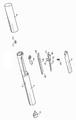
도 3은 도 1 및 도 2의 흡입기의 분해 사시도이다.Examples of inhalers according to the invention are described with reference to the accompanying drawings:
1 is a view through a perspective view of the first inhaler in a closed position;
2 is a similar view in the open position.
3 is an exploded perspective view of the inhaler of FIGS. 1 and 2;
본 발명은 호흡활성화 담배용 배출구 밸브의 향상에 관한 것으로, 단지 본 발명의 이 태양만이 특히 본 명세서에 기술되어 있다. 담배장치 및 리필장치의 나머지 구성의 세부내용에 대해서는 WO 2009/001078가 참조된다.The present invention relates to the improvement of an outlet valve for a breath-activated tobacco, only this aspect of the invention is described in particular herein. See WO 2009/001078 for details of the rest of the construction of the tobacco and refilling apparatus.
본 발명에 따른 흡입기의 제 1 예가 도 1 내지 도 3에 도시되어 있다.A first example of an inhaler according to the invention is shown in Figs.
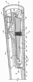
장치는 도 1에 도시된 바와 같이 메인 샤시(2)와 폐쇄요소(3)로 구성된 하우징(1)을 갖는다. 이는 라벨(4)에 의해 적소에 유지된다. 하우징내에, 흡입가능한 조성물을 담은 용기(5)가 있다. 이는 바람직하게는 가압되나 또한 용기에 강화된 흡입력을 발생하도록 벤트리 노즐과 결합해 비가압 용기 또는 실온에서 기화되는 경향이 있는 물질을 담은 비가압 용기와 작동할 수 있다. 이는 충전밸브(6)를 통해 WO 2009/001082에 기술된 바와 같이 재충전될 수 있거나, 장치는 1회용 장치이거나 용기(5)가 교체가능 부품이도록 배열될 수 있다. The device has a housing 1 consisting of a main chassis 2 and a
흡입활성화 밸브(7)가 배출구 단부(8)와 용기(5) 사이에 위치된다. 흡입활성화 밸브는 사용자가 배출구 단부(8)를 흡입할 때 흡입활성화 밸브(7)가 용기(5)로부터 흡입가능 조성물이 흡입될 수 있게 개방되도록 배열된다. A suction activation valve 7 is located between the outlet end 8 and the
배출구 단부에서 하우징은 2개의 오리피스가 있다. 이들 중 첫번째는 하기에 더 상세히 기술되는 바와 같이 챔버(10)와 통하는 흡입 오리피스(9)이며 두번째는 또한 하기에 더 상세히 기술된 흡입가능 조성물이 분출되는 배출구 오리피스(11)이다. 도 3에 명백한 바와 같이, 배출구 오리피스(11)는 분리 부품(12)에 제공된다.At the outlet end, the housing has two orifices. The first of these is the
용기(5)와 배출구 오리피스(11) 사이에 배출구 경로(13)가 정의된다.An
변형가능 튜브형소자(14)에 의해 배출구 경로(13)의 일부분이 제공된다. 이 튜브형소자는 도 1에 도시된 폐쇄위치와 도 2에 도시된 개방위치 사이에서 움직이며, 그 방식을 설명한다. A portion of the
이 방식은 피봇 장착 베인(15)과 멤브레인(16)을 구비한다. 멤브레인은 바람직하게는 예컨대 TPU 또는 TPE 재료, 가령, 크라이버그 제약(Kraiburg Pharmaceutical)의 TPE 등급 또는 메디프렌(mediprene), 산토프렌(Santoprene) 또는 네오프렌(Neoprene)로 몰딩된 사출이다. 피봇 장착 베인은 배출구 단부(8)에 가장 가까운 단부에 피봇(17)과 길이를 따라 이어지며 배출구 단부로부터 멀리 테이퍼지는 중앙보강리브(18)를 갖는다. 대안으로, 2 이상의 이격된 리브들이 있을 수 있다. 중앙점 주위에서, 베인(15)에는 도 1에 도시된 폐쇄위치로 바이어스시키는 스프링(20)을 수용하기 위한 오목부(19)가 제공된다. 오목부(19) 아래에는 베인(15)으로부터 제공된 힘을 좁은 영역 위의 변형가능 튜브(14)에 가하도록 구성된 삼각형 횡단면을 갖는 조(jaw)(21)가 있다. 밸브(15)는 격막에는 개구를 지나는 조(21)의 끼움에 의해 격막(16)에 의해 지지되고, 격막 상의 보스(16A)는 베인(15)상의 개구에 끼워진다. 격막(16)은 단부(22,23)에서 하우징에 밀봉된다. 이는 흡입 오리피스(9)에 대한 것이라기보다 챔버(10)를 봉쇄한다. 단부(23)에서, 격막(16)은 개방 및 폐쇄위치 사이에서 상기 단부의 이동을 수용하도록 주름져 있다. This method includes a
멤브레인(16)의 하부(24)는 배출구 경로(1) 주위로 뻗어 있고 따라서 도 1 및 도 2의 평면에 도시되어 있지 않는 도면에 미도시된 하우징(1)을 지나는 누출경로가 있기 때문에 대기압에 개방되어 있다.The
사용자가 도 1에 도시된 구성에서 장치를 이용해 배출구 단부(8)를 흡입할 때, 공기가 유입구 오리피스(25)를 통해 챔버(10)로 그리고 흡입 오리피스(9) 밖으로 흡입되므로 격막(16) 아래 압력에 대해 이 챔버에서 압력을 낮춘다. 격막(16)에 발생된 압력차는 흐름경로를 막는데 충분하다. 예컨대, 도 2에 도시된 위치로 스프링(20)의 동작에 대해 베인(15)을 들어올릴 수 있다. 이는 도 2에 도시된 구성으로 격막을 변형시키고 조(21)를 들어올려 변형가능 튜브를 개방하게 하여, 용기(5)로부터 흡입가능 조성물이 배출구 경로(13)를 따라 용기(5)로부터 변형가능 튜브(14)를 통해 그리고 배출구 오리피스(11)를 통해 밖으로 나가게 한다. 사용자에 의해 가해진 흡입 정도는 베인(15)이 움직이고 이에 따라 사용자가 받아들이는 조성물의 양 정도를 결정한다. 사용자가 흡입을 멈추자마자, 대기압이 흡입 오리피스(9)를 통해 챔버(10)에 되돌려지고 스프링(20)은 베인을 도 1의 위치로 복귀시켜 이로써 튜브(14)를 닫히게 조인다.When the user inhales the outlet end 8 with the device in the configuration shown in FIG. 1, the air is sucked through the
Claims (17)
용기를 수용하고 배출구 단부 및 대향 단부를 갖는 하우징과,
흐름경로를 따라 용기로부터 그리고 하우징의 배출구 단부에서 조성물의 배출구 밖으로 조성물의 흐름을 위한 조성물 흐름경로와,
공기 유입구로부터 하우징의 배출구 단부에 있는 공기 배출구로 공기흐름을 정의하는 하우징내에 있고, 격막의 일측 상의 공기 흐름경로를 격막의 맞은 편의 하우징의 나머지로부터 분리시키는 대향 단부를 향해 공기흐름 유입구를 지나 뻗어 있는 가요성 격막과,
격막과 함께 이동가능하며 편향력에 의해 조성물 흐름경로를 막는 위치로 편향되는 밸브요소를 구비하고,
유입구 단부에서의 흡입으로 공기흐름 챔버내 압력이 낮아짐으로써 편향력에 대해 밸브요소를 들어올려 조성물 흐름경로를 개방하게 하며,
편향력은 흡입이 중단된 후 조성물 흐름경로를 폐쇄하도록 배열되는 흡입기.A container of inhalable composition,
A housing for receiving the container and having an outlet end and an opposite end,
A composition flow path for the flow of the composition from the vessel along the flow path and out of the composition outlet at the outlet end of the housing,
An air outlet at the outlet end of the housing from the air inlet and within the housing defining the airflow and extending past the airflow inlet toward the opposite end separating the air flow path on one side of the diaphragm from the rest of the housing opposite the diaphragm. Flexible diaphragm,
A valve element movable with the diaphragm and deflected to a position blocking the composition flow path by the biasing force,
Intake at the inlet end lowers the pressure in the airflow chamber, thereby raising the valve element against deflection forces to open the composition flow path,
The biasing force is arranged to close the composition flow path after the inhalation stops.
조성물 흐름경로는 실질적으로 굴곡이 없는 직선경로인 흡입기.The method of claim 1,
The inhaler of the composition flow path is a straight path substantially free of bending.
가요성 격막의 대부분의 길이를 따라 뻗어 있는 베인을 더 구비하는 흡입기.The method according to claim 1 or 2,
An inhaler further comprising vanes extending along most of the length of the flexible diaphragm.
베인은 공기 유입구로부터 먼 단부에 피봇 장착되는 흡입기.The method of claim 3, wherein
The vane is pivotally mounted at an end remote from the air inlet.
밸브는 베인과 일체로 형성되는 흡입기.The method according to claim 3 or 4,
The valve is an inhaler formed integrally with the vane.
멤브레인은 흡입기의 전체 길의 적어도 1/4로 뻗어 있는 흡입기.6. The method according to any one of claims 1 to 5,
The membrane is an inhaler extending at least one quarter of the total length of the inhaler.
멤브레인은 흡입기의 전체 길이의 적어도 1/3로 뻗어 있는 흡입기.The method according to any one of claims 1 to 6,
The membrane extends at least one third of the total length of the inhaler.
조성물 흐름경로 중 적어도 일부분은 밸브요소에 의해 선택적으로 핀치되고 해제되는 변형가능한 튜브인 흡입기.The method according to any one of claims 1 to 7,
At least a portion of the composition flow path is a deformable tube that is selectively pinched and released by the valve element.
가요성 격막은 필요한 작동력이 2N 내지 20N 사이에 있도록 구성되는 흡입기.The method according to any one of claims 1 to 8,
The flexible diaphragm is configured such that the required operating force is between 2N and 20N.
가요성 격막은 필요한 작동력이 7N 내지 10N 사이에 있도록 구성되는 흡입기.The method according to any one of claims 1 to 9,
The flexible diaphragm is configured such that the required operating force is between 7N and 10N.
가요성 격막은 필요한 작동력이 실질적으로 5N이도록 구성되는 흡입기.11. The method according to any one of claims 1 to 10,
The flexible diaphragm is configured such that the required operating force is substantially 5N.
가요성 격막은 쇼어 에이(Shore A) 스케일로 20-80A의 경도를 갖는 흡입기.12. The method according to any one of claims 1 to 11,
The flexible diaphragm is an inhaler with a hardness of 20-80 A on the Shore A scale.
가요성 격막은 쇼어 에이(Shore A) 스케일로 30-40A의 경도를 갖는 흡입기.13. The method according to any one of claims 1 to 12,
The flexible diaphragm is an inhaler with a hardness of 30-40 A on the Shore A scale.
설계시, 둘러싼 하우징에 의해 고정되는 임의의 부분들을 배제하지 않고 베인에 의해 커버되는 임의의 부분들을 포함하는 가요성 격막의 전체 면적이 100㎟ 내지 150㎟ 사이에 있는 흡입기.14. The method according to any one of claims 1 to 13,
In design, the inhaler having a total area of between 100 mm 2 and 150 mm 2 of flexible diaphragm including any parts covered by vanes without excluding any parts fixed by the surrounding housing.
설계시, 둘러싼 하우징에 의해 고정되는 임의의 부분들을 배제하지 않고 베인에 의해 커버되는 임의의 부분들을 포함하는 공기흐름에 노출된 가요성 격막의 전체 면적이 150㎟ 내지 250㎟ 사이에 있는 흡입기.The method according to any one of claims 1 to 14,
In design, the inhaler having a total area of between 150 mm 2 and 250 mm 2 of the flexible diaphragm exposed to the airflow, including any parts covered by vanes, without excluding any parts fixed by the surrounding housing.
설계시, 둘러싼 하우징에 의해 고정되는 임의의 부분들을 배제하지 않고 베인에 의해 커버되는 임의의 부분들을 포함하는 공기흐름에 노출된 가요성 격막의 전체 면적이 실질적으로 200㎟인 흡입기.The method according to any one of claims 1 to 15,
In design, an inhaler wherein the total area of the flexible diaphragm exposed to the airflow, including any portions covered by vanes, without excluding any portions secured by the surrounding housing, is substantially 200 mm 2.
흡입기는 모조 담배인 흡입기.The method according to any one of claims 1 to 16,
Inhalers are imitation cigarettes.
Applications Claiming Priority (7)
| Application Number | Priority Date | Filing Date | Title |
|---|---|---|---|
| GB0913942A GB0913942D0 (en) | 2009-08-07 | 2009-08-07 | An inhaler |
| GB0913942.9 | 2009-08-07 | ||
| GBGB1000403.4A GB201000403D0 (en) | 2010-01-11 | 2010-01-11 | An inhaler |
| GB1000403.4 | 2010-01-11 | ||
| GB1002024.6 | 2010-02-08 | ||
| GBGB1002024.6A GB201002024D0 (en) | 2009-08-07 | 2010-02-08 | An inhaler |
| PCT/GB2010/001488 WO2011015826A1 (en) | 2009-08-07 | 2010-08-06 | An inhaler |
Publications (2)
| Publication Number | Publication Date |
|---|---|
| KR20120052960A true KR20120052960A (en) | 2012-05-24 |
| KR101739481B1 KR101739481B1 (en) | 2017-05-24 |
Family
ID=43543968
Family Applications (2)
| Application Number | Title | Priority Date | Filing Date |
|---|---|---|---|
| KR1020127003066A KR101739481B1 (en) | 2009-08-07 | 2010-08-06 | An inhaler |
| KR1020127003067A KR101734932B1 (en) | 2009-08-07 | 2010-08-06 | An inhaler |
Family Applications After (1)
| Application Number | Title | Priority Date | Filing Date |
|---|---|---|---|
| KR1020127003067A KR101734932B1 (en) | 2009-08-07 | 2010-08-06 | An inhaler |
Country Status (24)
| Country | Link |
|---|---|
| US (3) | US10456539B2 (en) |
| EP (2) | EP2461858B1 (en) |
| JP (2) | JP5663017B2 (en) |
| KR (2) | KR101739481B1 (en) |
| CN (2) | CN102470227B (en) |
| AU (2) | AU2010280530B2 (en) |
| BR (2) | BR112012002718B8 (en) |
| CA (2) | CA2765907C (en) |
| CL (2) | CL2012000321A1 (en) |
| DK (1) | DK2461857T3 (en) |
| ES (2) | ES2814230T3 (en) |
| GB (2) | GB2476611B (en) |
| HK (2) | HK1157255A1 (en) |
| HU (1) | HUE047196T2 (en) |
| IL (2) | IL217969A (en) |
| IN (1) | IN2012DN00527A (en) |
| MX (2) | MX2012001533A (en) |
| MY (2) | MY160158A (en) |
| NZ (2) | NZ597287A (en) |
| PL (1) | PL2461857T3 (en) |
| PT (1) | PT2461857T (en) |
| RU (2) | RU2529387C2 (en) |
| WO (2) | WO2011015826A1 (en) |
| ZA (2) | ZA201200491B (en) |
Families Citing this family (97)
| Publication number | Priority date | Publication date | Assignee | Title |
|---|---|---|---|---|
| US10244793B2 (en) | 2005-07-19 | 2019-04-02 | Juul Labs, Inc. | Devices for vaporization of a substance |
| KR101739481B1 (en) | 2009-08-07 | 2017-05-24 | 카인드 컨슈머 리미티드 | An inhaler |
| GB201001944D0 (en) | 2010-02-05 | 2010-03-24 | Kind Consumer Ltd | A simulated smoking device |
| GB201004861D0 (en) | 2010-03-23 | 2010-05-05 | Kind Consumer Ltd | A simulated cigarette |
| US10136672B2 (en) | 2010-05-15 | 2018-11-27 | Rai Strategic Holdings, Inc. | Solderless directly written heating elements |
| US9861772B2 (en) | 2010-05-15 | 2018-01-09 | Rai Strategic Holdings, Inc. | Personal vaporizing inhaler cartridge |
| US10159278B2 (en) | 2010-05-15 | 2018-12-25 | Rai Strategic Holdings, Inc. | Assembly directed airflow |
| US9259035B2 (en) | 2010-05-15 | 2016-02-16 | R. J. Reynolds Tobacco Company | Solderless personal vaporizing inhaler |
| US9743691B2 (en) | 2010-05-15 | 2017-08-29 | Rai Strategic Holdings, Inc. | Vaporizer configuration, control, and reporting |
| US9095175B2 (en) | 2010-05-15 | 2015-08-04 | R. J. Reynolds Tobacco Company | Data logging personal vaporizing inhaler |
| US8757147B2 (en) | 2010-05-15 | 2014-06-24 | Minusa Holdings Llc | Personal vaporizing inhaler with internal light source |
| US9999250B2 (en) | 2010-05-15 | 2018-06-19 | Rai Strategic Holdings, Inc. | Vaporizer related systems, methods, and apparatus |
| US8578942B2 (en) | 2010-05-25 | 2013-11-12 | British American Tobacco (Investments) Limited | Aerosol generator |
| US20110290248A1 (en) * | 2010-05-25 | 2011-12-01 | Steven Michael Schennum | Aerosol Generator |
| US8689786B2 (en) | 2010-05-25 | 2014-04-08 | British American Tobacco (Investments) Limited | Aerosol generator |
| US8950395B2 (en) | 2010-05-25 | 2015-02-10 | Nicoventures Holdings Limited | Aerosol generator |
| US9854839B2 (en) | 2012-01-31 | 2018-01-02 | Altria Client Services Llc | Electronic vaping device and method |
| US9022023B2 (en) * | 2012-06-29 | 2015-05-05 | Carefusion 207, Inc. | Breath actuated nebulizer having a pressurized gas diverter with a diverter orifice |
| MX366378B (en) * | 2012-08-28 | 2019-07-05 | Kind Consumer Ltd | An inhaler. |
| GB201215282D0 (en) | 2012-08-28 | 2012-10-10 | Kind Consumer Ltd | An inhaler |
| RU2617984C2 (en) * | 2012-09-28 | 2017-04-28 | Кимри Хай-Тек Инк. | Electronic cigarette and respective electronic cigarette apparatus |
| US10034988B2 (en) | 2012-11-28 | 2018-07-31 | Fontem Holdings I B.V. | Methods and devices for compound delivery |
| US10279934B2 (en) | 2013-03-15 | 2019-05-07 | Juul Labs, Inc. | Fillable vaporizer cartridge and method of filling |
| GB2512329B (en) * | 2013-03-26 | 2015-08-19 | Kind Consumer Ltd | A Simulated Cigarette |
| GB2513553B (en) * | 2013-03-26 | 2015-03-18 | Kind Consumer Ltd | An Inhaler |
| GB2520105B (en) | 2013-03-26 | 2017-10-18 | Kind Consumer Ltd | A pressurised refill canister with an outlet valve |
| GB2512326B (en) | 2013-03-26 | 2016-02-24 | Kind Consumer Ltd | A pressurised refill canister with an outlet valve |
| GB2514758B (en) | 2013-03-26 | 2015-06-24 | Kind Consumer Ltd | A Pressurised Refill Canister with an Outlet Valve |
| CN203378557U (en) * | 2013-06-19 | 2014-01-08 | 刘秋明 | Electronic cigarette |
| US10194693B2 (en) | 2013-09-20 | 2019-02-05 | Fontem Holdings 1 B.V. | Aerosol generating device |
| GB2519950A (en) * | 2013-10-30 | 2015-05-13 | British American Tobacco Co | An Inhaler |
| USD842536S1 (en) | 2016-07-28 | 2019-03-05 | Juul Labs, Inc. | Vaporizer cartridge |
| USD825102S1 (en) | 2016-07-28 | 2018-08-07 | Juul Labs, Inc. | Vaporizer device with cartridge |
| US10159282B2 (en) | 2013-12-23 | 2018-12-25 | Juul Labs, Inc. | Cartridge for use with a vaporizer device |
| US10076139B2 (en) | 2013-12-23 | 2018-09-18 | Juul Labs, Inc. | Vaporizer apparatus |
| DE202014011297U1 (en) | 2013-12-23 | 2019-02-13 | Juul Labs Uk Holdco Limited | Systems for an evaporation device |
| US10058129B2 (en) | 2013-12-23 | 2018-08-28 | Juul Labs, Inc. | Vaporization device systems and methods |
| US20160366947A1 (en) | 2013-12-23 | 2016-12-22 | James Monsees | Vaporizer apparatus |
| GB2524469A (en) * | 2014-02-14 | 2015-09-30 | Kind Consumer Ltd | A cannabinoid inhaler and composition therefor |
| US9918961B2 (en) | 2014-02-19 | 2018-03-20 | Kind Consumer Limited | Cannabinoid inhaler and composition therefor |
| GB2528068B (en) | 2014-07-08 | 2017-02-15 | Kind Consumer Ltd | An inhaler |
| CN104223363B (en) * | 2014-08-20 | 2017-02-15 | 深圳麦克韦尔股份有限公司 | Inhalator |
| WO2016026093A1 (en) * | 2014-08-20 | 2016-02-25 | 深圳麦克韦尔股份有限公司 | Inhaler |
| GB2534336A (en) * | 2014-09-26 | 2016-07-27 | Kind Consumer Ltd | A method of assembling and testing a simulated cigarette |
| WO2016089981A1 (en) * | 2014-12-04 | 2016-06-09 | Carefusion 2200, Inc. | Breath-actuated nebulizer for medicine inhalation |
| KR102627987B1 (en) | 2014-12-05 | 2024-01-22 | 쥴 랩스, 인크. | Calibrated dose control |
| US10111462B2 (en) * | 2015-01-26 | 2018-10-30 | Joseph Miguel Doyle | Vaporizer protective case |
| WO2017047481A1 (en) * | 2015-09-14 | 2017-03-23 | アイエス・テクノロジー・ジャパン株式会社 | Switching valve, and suction/discharge device provided with same |
| RU2609889C1 (en) * | 2015-10-22 | 2017-02-06 | Александр Владимирович Горшков | Device for reduction of stomach volume |
| TW201714534A (en) | 2015-10-22 | 2017-05-01 | 菲利浦莫里斯製品股份有限公司 | Aerosol delivery system and method of operating the aerosol delivery system |
| CN205196999U (en) * | 2015-11-23 | 2016-05-04 | 深圳市合元科技有限公司 | Atomizer and electronic cigarette |
| US10206432B2 (en) | 2015-12-24 | 2019-02-19 | Altria Client Services Llc | Flexible aerosol-generating devices |
| JP6929846B2 (en) | 2015-12-24 | 2021-09-01 | フィリップ・モーリス・プロダクツ・ソシエテ・アノニム | Flexible aerosol generator |
| US10015989B2 (en) * | 2016-01-27 | 2018-07-10 | Rai Strategic Holdings, Inc. | One-way valve for refilling an aerosol delivery device |
| WO2017139595A1 (en) | 2016-02-11 | 2017-08-17 | Pax Labs, Inc. | Fillable vaporizer cartridge and method of filling |
| EA039727B1 (en) | 2016-02-11 | 2022-03-04 | Джуул Лэбз, Инк. | Securely attaching cartridges for vaporizer devices |
| GB2550538B (en) * | 2016-02-19 | 2018-05-09 | Kind Consumer Ltd | An inhaler |
| US10405582B2 (en) | 2016-03-10 | 2019-09-10 | Pax Labs, Inc. | Vaporization device with lip sensing |
| FR3050114B1 (en) * | 2016-04-15 | 2021-12-03 | Aptar France Sas | FLUID PRODUCT DISTRIBUTION DEVICE SYNCHRONIZED WITH INHALATION. |
| FR3050116B1 (en) * | 2016-04-15 | 2020-05-15 | Aptar France Sas | DEVICE FOR DISPENSING SYNCHRONIZED FLUID PRODUCT WITH INHALATION |
| FR3050115B1 (en) * | 2016-04-15 | 2023-05-12 | Aptar France Sas | FLUID PRODUCT DELIVERY DEVICE SYNCHRONIZED WITH INHALATION. |
| GB2549769A (en) * | 2016-04-28 | 2017-11-01 | Kind Consumer Ltd | An Inhaler |
| USD849996S1 (en) | 2016-06-16 | 2019-05-28 | Pax Labs, Inc. | Vaporizer cartridge |
| USD848057S1 (en) | 2016-06-23 | 2019-05-07 | Pax Labs, Inc. | Lid for a vaporizer |
| USD836541S1 (en) | 2016-06-23 | 2018-12-25 | Pax Labs, Inc. | Charging device |
| USD851830S1 (en) | 2016-06-23 | 2019-06-18 | Pax Labs, Inc. | Combined vaporizer tamp and pick tool |
| CN106390252B (en) * | 2016-08-30 | 2019-07-30 | 苏州涵轩信息科技有限公司 | A kind of medicinal liquid atomizer |
| CN106993825B (en) * | 2017-05-04 | 2019-12-27 | 黄印坤 | Arab hookah |
| KR20190049391A (en) | 2017-10-30 | 2019-05-09 | 주식회사 케이티앤지 | Aerosol generating apparatus having heater |
| USD887632S1 (en) | 2017-09-14 | 2020-06-16 | Pax Labs, Inc. | Vaporizer cartridge |
| GB2567240B (en) | 2017-10-09 | 2022-04-06 | Senzer Ltd | An inhaler particularly a cannabinoid inhaler and a method of assembling such an inhaler |
| KR102057215B1 (en) | 2017-10-30 | 2019-12-18 | 주식회사 케이티앤지 | Method and apparatus for generating aerosols |
| KR102138245B1 (en) | 2017-10-30 | 2020-07-28 | 주식회사 케이티앤지 | Aerosol generating apparatus |
| EP4008204A1 (en) | 2017-10-30 | 2022-06-08 | KT&G Corporation | Aerosol generation device and method for controlling same |
| US11369145B2 (en) | 2017-10-30 | 2022-06-28 | Kt&G Corporation | Aerosol generating device including detachable vaporizer |
| KR102138246B1 (en) | 2017-10-30 | 2020-07-28 | 주식회사 케이티앤지 | Vaporizer and aerosol generating apparatus comprising the same |
| JP6978580B2 (en) | 2017-10-30 | 2021-12-08 | ケイティー アンド ジー コーポレイション | Heaters for aerosol generators and aerosol generators |
| EP3704964A4 (en) | 2017-10-30 | 2021-09-15 | KT&G Corporation | Aerosol generating device |
| KR102057216B1 (en) | 2017-10-30 | 2019-12-18 | 주식회사 케이티앤지 | An apparatus for generating aerosols and A heater assembly therein |
| KR102180421B1 (en) * | 2017-10-30 | 2020-11-18 | 주식회사 케이티앤지 | Apparatus for generating aerosols |
| CA3085180A1 (en) * | 2017-12-12 | 2019-06-20 | Jt International Sa | Fluid supply system for an electronic cigarette |
| US20200345588A1 (en) * | 2018-01-16 | 2020-11-05 | The Trustees Of Indiana University | Monitor device for real time compliance instructions and user feedback and clinician communication |
| US11464925B2 (en) | 2018-06-04 | 2022-10-11 | Trudell Medical International | Positive air pressure therapy device, kit and methods for the use and assembly thereof |
| US11813397B2 (en) | 2019-06-11 | 2023-11-14 | Justin Rowley | Nebulizer with flutter valve |
| GB2586301B (en) * | 2020-04-07 | 2021-08-25 | Splash Tm Gmbh | Stable-Foam inhalation Device and Cartridge |
| GB2595692A (en) | 2020-06-03 | 2021-12-08 | Senzer Ltd | A refill for an inhaler particularly a cannabinoid inhaler |
| US20220079249A1 (en) * | 2020-09-16 | 2022-03-17 | Capnos Llc | Reservoir-less vaping-alternative devices and related methods |
| CN117241687A (en) * | 2021-05-10 | 2023-12-15 | 日本烟草产业株式会社 | Power supply unit for aerosol-generating device |
| KR102604614B1 (en) | 2021-08-03 | 2023-11-20 | 주식회사 케이티앤지 | Nicotine inhaler |
| KR102620744B1 (en) | 2021-08-18 | 2024-01-02 | 주식회사 케이티앤지 | Nicotine inhaler |
| US11751585B1 (en) | 2022-05-13 | 2023-09-12 | Sharkninja Operating Llc | Flavored beverage carbonation system |
| US11745996B1 (en) | 2022-11-17 | 2023-09-05 | Sharkninja Operating Llc | Ingredient containers for use with beverage dispensers |
| US11738988B1 (en) | 2022-11-17 | 2023-08-29 | Sharkninja Operating Llc | Ingredient container valve control |
| US11634314B1 (en) * | 2022-11-17 | 2023-04-25 | Sharkninja Operating Llc | Dosing accuracy |
| US11925287B1 (en) | 2023-03-22 | 2024-03-12 | Sharkninja Operating Llc | Additive container with inlet tube |
| US11871867B1 (en) | 2023-03-22 | 2024-01-16 | Sharkninja Operating Llc | Additive container with bottom cover |
| US11931704B1 (en) | 2023-06-16 | 2024-03-19 | Sharkninja Operating Llc | Carbonation chamber |
Family Cites Families (56)
| Publication number | Priority date | Publication date | Assignee | Title |
|---|---|---|---|---|
| US2814290A (en) * | 1952-04-25 | 1957-11-26 | Bendix Aviat Corp | Respiratory apparatus |
| US2989970A (en) * | 1956-09-05 | 1961-06-27 | Globe Ind Inc | Demand inhalator |
| US3187748A (en) * | 1963-04-29 | 1965-06-08 | Merck And Company Inc | Inhalation-actuated aerosol device |
| US3456646A (en) * | 1967-01-19 | 1969-07-22 | Dart Ind Inc | Inhalation-actuated aerosol dispensing device |
| FR1601834A (en) * | 1968-07-30 | 1970-09-14 | ||
| US3631856A (en) | 1969-09-22 | 1972-01-04 | Ruth E Taylor | Substitute smoking article dispensing oxygen to provide a physiological lift |
| US3721240A (en) * | 1970-11-10 | 1973-03-20 | M Tamburri | Mechanical smoking device |
| US4054133A (en) * | 1976-03-29 | 1977-10-18 | The Bendix Corporation | Control for a demand cannula |
| US4195810A (en) * | 1978-03-31 | 1980-04-01 | Lavin Aaron M | Pinch valve |
| US4393884A (en) | 1981-09-25 | 1983-07-19 | Jacobs Allen W | Demand inhaler for oral administration of tobacco, tobacco-like, or other substances |
| US4955372A (en) * | 1985-07-16 | 1990-09-11 | Transpirator Technologies, Inc. | Method and apparatus for pulmonary and cardiovascular conditioning of racehorses and competition animals |
| GB8614805D0 (en) * | 1986-06-18 | 1986-07-23 | British American Tobacco Co | Aerosol device |
| US4955371A (en) | 1989-05-08 | 1990-09-11 | Transtech Scientific, Inc. | Disposable inhalation activated, aerosol device for pulmonary medicine |
| US5297542A (en) * | 1989-06-22 | 1994-03-29 | Raymond J. Bacon | Aerosol dispensing device |
| US4945931A (en) * | 1989-07-14 | 1990-08-07 | Brown & Williamson Tobacco Corporation | Simulated smoking device |
| US6039078A (en) * | 1989-09-22 | 2000-03-21 | Tamari; Yehuda | Inline extracorporeal reservoir and pressure isolator |
| US5507281A (en) * | 1990-08-30 | 1996-04-16 | Boehringer Ingelheim Kg | Device for initiating a mechanical switching operation in synchronism with the breathing |
| US5027808A (en) | 1990-10-31 | 1991-07-02 | Tenax Corporation | Breath-activated inhalation device |
| GB9026191D0 (en) * | 1990-12-01 | 1991-01-16 | Harris Pharma Ltd | Breath actuated dispensing device |
| US5161524A (en) * | 1991-08-02 | 1992-11-10 | Glaxo Inc. | Dosage inhalator with air flow velocity regulating means |
| US6029661A (en) * | 1991-08-26 | 2000-02-29 | 3M Innovative Properties Company | Powder dispenser |
| US5598840A (en) | 1995-03-17 | 1997-02-04 | Sorenson Critical Care, Inc. | Apparatus and method for ventilation and aspiration |
| US5738087A (en) * | 1995-09-21 | 1998-04-14 | King; Russell W. | Aerosol medication delivery system |
| US5839430A (en) * | 1996-04-26 | 1998-11-24 | Cama; Joseph | Combination inhaler and peak flow rate meter |
| US6803987B2 (en) * | 1996-07-03 | 2004-10-12 | Joseph S. Manne | Portable scent delivery system |
| GB9705657D0 (en) * | 1997-03-19 | 1997-05-07 | Bacon Raymond J | Dispenser |
| US5901745A (en) * | 1997-06-19 | 1999-05-11 | The Hoover Company | Multi-solution dispensing valve |
| AUPP240198A0 (en) * | 1998-03-17 | 1998-04-09 | Resmed Limited | An apparatus for supplying breathable gas |
| US6589197B1 (en) * | 1998-08-19 | 2003-07-08 | Jms Co., Ltd. | Fluid passage change-over apparatus for medical treatment |
| EP1169244B1 (en) * | 1999-03-12 | 2005-11-02 | Glaxo Group Limited | Metering valve |
| US6318366B1 (en) * | 1999-09-22 | 2001-11-20 | Salter Labs | Supply valve and diaphragm for a pneumatically-operated gas demand apparatus |
| SE9903990D0 (en) | 1999-11-02 | 1999-11-02 | Shl Medical Ab | Inhaler with aerosolizing unit |
| US6581590B1 (en) * | 2000-03-21 | 2003-06-24 | Iep Pharmaceutical Devices Inc. | Inhalation actuated device |
| US6637432B2 (en) * | 2000-05-09 | 2003-10-28 | Iep Pharmaceutical Devices Inc. | Inhalation actuated device |
| US7093594B2 (en) | 2000-09-29 | 2006-08-22 | Pfizer Limited | Dosing device |
| GB0029612D0 (en) * | 2000-12-05 | 2001-01-17 | Bacon Raymond J | Drug dispenser |
| EP1253360B1 (en) | 2000-12-05 | 2005-08-24 | Asahi Organic Chemicals Industry Co., Ltd. | Pinch valve |
| JP2004520092A (en) * | 2001-09-24 | 2004-07-08 | ピィ・エイ・ノレッジ・リミテッド | Pressure response means and related manufacturing method |
| US7028689B2 (en) * | 2001-11-21 | 2006-04-18 | 3M Innovative Properties Company | Filtering face mask that uses an exhalation valve that has a multi-layered flexible flap |
| US6994083B2 (en) * | 2001-12-21 | 2006-02-07 | Trudell Medical International | Nebulizer apparatus and method |
| RU2311859C2 (en) * | 2002-05-13 | 2007-12-10 | Тинк! Глобал Б.В. | Inhaler |
| EP1558317A2 (en) * | 2002-11-04 | 2005-08-03 | Cambridge Consultants Limited | Pressurised inhalers |
| US7013888B2 (en) | 2002-12-19 | 2006-03-21 | Scadds Incorporated | Self contained aerosol dual delivery system (SCADDS) |
| US7188622B2 (en) * | 2003-06-19 | 2007-03-13 | 3M Innovative Properties Company | Filtering face mask that has a resilient seal surface in its exhalation valve |
| US20050010996A1 (en) * | 2003-07-17 | 2005-01-20 | Steinert Robert B. | Protective suit ventilated by self-powered bellows |
| FR2881120B1 (en) * | 2005-01-25 | 2010-07-30 | Valois Sas | DEVICE FOR DISPENSING FLUID PRODUCT. |
| WO2008049433A1 (en) * | 2006-10-27 | 2008-05-02 | Trendtech A/S | Hand-held drug inhaler for administration of pharmaceutical or technical products |
| JP4834148B2 (en) * | 2007-03-30 | 2011-12-14 | 富士通セミコンダクター株式会社 | Data transfer method and data transfer apparatus |
| US20080257367A1 (en) | 2007-04-23 | 2008-10-23 | Greg Paterno | Electronic evaporable substance delivery device and method |
| DK2162025T3 (en) * | 2007-06-25 | 2014-09-01 | Kind Consumer Ltd | CIGARET SIMULATING DEVICE |
| GB0712305D0 (en) | 2007-06-25 | 2007-08-01 | Kind Group Ltd | A system comprising a simulated cigarette device and a refill unit |
| KR101221181B1 (en) * | 2007-12-05 | 2013-01-10 | 니뽄 다바코 산교 가부시키가이샤 | Aerosol aspirator |
| GB0823491D0 (en) * | 2008-12-23 | 2009-01-28 | Kind Consumer Ltd | A simulated cigarette device |
| KR101739481B1 (en) | 2009-08-07 | 2017-05-24 | 카인드 컨슈머 리미티드 | An inhaler |
| US9227030B2 (en) * | 2009-12-23 | 2016-01-05 | Map Pharmaceuticals, Inc. | Enhanced eductor design |
| US8671934B2 (en) * | 2011-01-20 | 2014-03-18 | Pneumoflex Systems, Llc | Nebulizer that is activated by negative inspiratory pressure |
-
2010
- 2010-08-06 KR KR1020127003066A patent/KR101739481B1/en active IP Right Grant
- 2010-08-06 AU AU2010280530A patent/AU2010280530B2/en active Active
- 2010-08-06 BR BR112012002718A patent/BR112012002718B8/en active IP Right Grant
- 2010-08-06 EP EP10744977.9A patent/EP2461858B1/en active Active
- 2010-08-06 BR BR112012002716-6A patent/BR112012002716A2/en not_active IP Right Cessation
- 2010-08-06 RU RU2012108574/14A patent/RU2529387C2/en not_active IP Right Cessation
- 2010-08-06 WO PCT/GB2010/001488 patent/WO2011015826A1/en active Application Filing
- 2010-08-06 KR KR1020127003067A patent/KR101734932B1/en active IP Right Grant
- 2010-08-06 IN IN527DEN2012 patent/IN2012DN00527A/en unknown
- 2010-08-06 CN CN201080034592.9A patent/CN102470227B/en active Active
- 2010-08-06 CA CA2765907A patent/CA2765907C/en not_active Expired - Fee Related
- 2010-08-06 MY MYPI2012000503A patent/MY160158A/en unknown
- 2010-08-06 PT PT107447096T patent/PT2461857T/en unknown
- 2010-08-06 JP JP2012523380A patent/JP5663017B2/en not_active Expired - Fee Related
- 2010-08-06 ES ES10744977T patent/ES2814230T3/en active Active
- 2010-08-06 CN CN201080034236.7A patent/CN102470226B/en active Active
- 2010-08-06 CA CA2768096A patent/CA2768096C/en active Active
- 2010-08-06 HU HUE10744709A patent/HUE047196T2/en unknown
- 2010-08-06 GB GB1106396A patent/GB2476611B/en active Active
- 2010-08-06 AU AU2010280531A patent/AU2010280531B2/en not_active Ceased
- 2010-08-06 NZ NZ597287A patent/NZ597287A/en not_active IP Right Cessation
- 2010-08-06 DK DK10744709T patent/DK2461857T3/en active
- 2010-08-06 RU RU2012108573/14A patent/RU2529693C2/en active
- 2010-08-06 US US13/389,431 patent/US10456539B2/en active Active
- 2010-08-06 PL PL10744709T patent/PL2461857T3/en unknown
- 2010-08-06 ES ES10744709T patent/ES2750269T3/en active Active
- 2010-08-06 MX MX2012001533A patent/MX2012001533A/en active IP Right Grant
- 2010-08-06 US US13/389,434 patent/US9408987B2/en active Active
- 2010-08-06 MY MYPI2012000482A patent/MY163805A/en unknown
- 2010-08-06 WO PCT/GB2010/001487 patent/WO2011015825A1/en active Application Filing
- 2010-08-06 MX MX2012001569A patent/MX2012001569A/en unknown
- 2010-08-06 GB GB1106397.1A patent/GB2476612B/en active Active
- 2010-08-06 EP EP10744709.6A patent/EP2461857B1/en active Active
- 2010-08-06 JP JP2012523379A patent/JP5663016B2/en active Active
- 2010-08-06 NZ NZ597380A patent/NZ597380A/en unknown
-
2011
- 2011-10-27 HK HK11111621.1A patent/HK1157255A1/en not_active IP Right Cessation
- 2011-10-27 HK HK11111620.2A patent/HK1157254A1/en unknown
-
2012
- 2012-01-20 ZA ZA2012/00491A patent/ZA201200491B/en unknown
- 2012-01-20 ZA ZA2012/00487A patent/ZA201200487B/en unknown
- 2012-02-06 IL IL217969A patent/IL217969A/en active IP Right Grant
- 2012-02-06 IL IL217968A patent/IL217968A/en not_active IP Right Cessation
- 2012-02-07 CL CL2012000321A patent/CL2012000321A1/en unknown
- 2012-02-07 CL CL2012000322A patent/CL2012000322A1/en unknown
-
2016
- 2016-07-08 US US15/205,166 patent/US10543324B2/en active Active
Also Published As
Similar Documents
| Publication | Publication Date | Title |
|---|---|---|
| KR20120052960A (en) | An inhaler | |
| DK2890257T3 (en) | INHALER | |
| DK2890258T3 (en) | Breathing enabled inhaler with an injection of air flows in the tab | |
| TW201231104A (en) | An inhaler | |
| TW201231103A (en) | An inhaler |
Legal Events
| Date | Code | Title | Description |
|---|---|---|---|
| A201 | Request for examination | ||
| E902 | Notification of reason for refusal | ||
| E701 | Decision to grant or registration of patent right | ||
| GRNT | Written decision to grant |