KR20120051667A - Three-layer steel cord that is rubberized in situ and has a 3+m+n structure - Google Patents
Three-layer steel cord that is rubberized in situ and has a 3+m+n structure Download PDFInfo
- Publication number
- KR20120051667A KR20120051667A KR1020127002909A KR20127002909A KR20120051667A KR 20120051667 A KR20120051667 A KR 20120051667A KR 1020127002909 A KR1020127002909 A KR 1020127002909A KR 20127002909 A KR20127002909 A KR 20127002909A KR 20120051667 A KR20120051667 A KR 20120051667A
- Authority
- KR
- South Korea
- Prior art keywords
- layer
- cord
- wires
- rubber
- tire
- Prior art date
Links
Images

Classifications
-
- D—TEXTILES; PAPER
- D07—ROPES; CABLES OTHER THAN ELECTRIC
- D07B—ROPES OR CABLES IN GENERAL
- D07B1/00—Constructional features of ropes or cables
- D07B1/06—Ropes or cables built-up from metal wires, e.g. of section wires around a hemp core
- D07B1/0606—Reinforcing cords for rubber or plastic articles
- D07B1/0613—Reinforcing cords for rubber or plastic articles the reinforcing cords being characterised by the rope configuration
-
- B—PERFORMING OPERATIONS; TRANSPORTING
- B60—VEHICLES IN GENERAL
- B60C—VEHICLE TYRES; TYRE INFLATION; TYRE CHANGING; CONNECTING VALVES TO INFLATABLE ELASTIC BODIES IN GENERAL; DEVICES OR ARRANGEMENTS RELATED TO TYRES
- B60C9/00—Reinforcements or ply arrangement of pneumatic tyres
- B60C9/0007—Reinforcements made of metallic elements, e.g. cords, yarns, filaments or fibres made from metal
-
- D—TEXTILES; PAPER
- D07—ROPES; CABLES OTHER THAN ELECTRIC
- D07B—ROPES OR CABLES IN GENERAL
- D07B1/00—Constructional features of ropes or cables
- D07B1/06—Ropes or cables built-up from metal wires, e.g. of section wires around a hemp core
- D07B1/0606—Reinforcing cords for rubber or plastic articles
- D07B1/062—Reinforcing cords for rubber or plastic articles the reinforcing cords being characterised by the strand configuration
- D07B1/0626—Reinforcing cords for rubber or plastic articles the reinforcing cords being characterised by the strand configuration the reinforcing cords consisting of three core wires or filaments and at least one layer of outer wires or filaments, i.e. a 3+N configuration
-
- D—TEXTILES; PAPER
- D07—ROPES; CABLES OTHER THAN ELECTRIC
- D07B—ROPES OR CABLES IN GENERAL
- D07B1/00—Constructional features of ropes or cables
- D07B1/06—Ropes or cables built-up from metal wires, e.g. of section wires around a hemp core
- D07B1/0606—Reinforcing cords for rubber or plastic articles
- D07B1/062—Reinforcing cords for rubber or plastic articles the reinforcing cords being characterised by the strand configuration
- D07B1/0633—Reinforcing cords for rubber or plastic articles the reinforcing cords being characterised by the strand configuration having a multiple-layer configuration
-
- D—TEXTILES; PAPER
- D07—ROPES; CABLES OTHER THAN ELECTRIC
- D07B—ROPES OR CABLES IN GENERAL
- D07B1/00—Constructional features of ropes or cables
- D07B1/06—Ropes or cables built-up from metal wires, e.g. of section wires around a hemp core
- D07B1/0606—Reinforcing cords for rubber or plastic articles
- D07B1/0646—Reinforcing cords for rubber or plastic articles comprising longitudinally preformed wires
- D07B1/0653—Reinforcing cords for rubber or plastic articles comprising longitudinally preformed wires in the core
-
- D—TEXTILES; PAPER
- D07—ROPES; CABLES OTHER THAN ELECTRIC
- D07B—ROPES OR CABLES IN GENERAL
- D07B1/00—Constructional features of ropes or cables
- D07B1/16—Ropes or cables with an enveloping sheathing or inlays of rubber or plastics
-
- D—TEXTILES; PAPER
- D07—ROPES; CABLES OTHER THAN ELECTRIC
- D07B—ROPES OR CABLES IN GENERAL
- D07B3/00—General-purpose machines or apparatus for producing twisted ropes or cables from component strands of the same or different material
- D07B3/02—General-purpose machines or apparatus for producing twisted ropes or cables from component strands of the same or different material in which the supply reels rotate about the axis of the rope or cable or in which a guide member rotates about the axis of the rope or cable to guide the component strands away from the supply reels in fixed position
-
- D—TEXTILES; PAPER
- D07—ROPES; CABLES OTHER THAN ELECTRIC
- D07B—ROPES OR CABLES IN GENERAL
- D07B5/00—Making ropes or cables from special materials or of particular form
- D07B5/12—Making ropes or cables from special materials or of particular form of low twist or low tension by processes comprising setting or straightening treatments
-
- D—TEXTILES; PAPER
- D07—ROPES; CABLES OTHER THAN ELECTRIC
- D07B—ROPES OR CABLES IN GENERAL
- D07B7/00—Details of, or auxiliary devices incorporated in, rope- or cable-making machines; Auxiliary apparatus associated with such machines
- D07B7/02—Machine details; Auxiliary devices
- D07B7/14—Machine details; Auxiliary devices for coating or wrapping ropes, cables, or component strands thereof
- D07B7/145—Coating or filling-up interstices
-
- D—TEXTILES; PAPER
- D07—ROPES; CABLES OTHER THAN ELECTRIC
- D07B—ROPES OR CABLES IN GENERAL
- D07B1/00—Constructional features of ropes or cables
- D07B1/06—Ropes or cables built-up from metal wires, e.g. of section wires around a hemp core
- D07B1/0606—Reinforcing cords for rubber or plastic articles
- D07B1/0646—Reinforcing cords for rubber or plastic articles comprising longitudinally preformed wires
-
- D—TEXTILES; PAPER
- D07—ROPES; CABLES OTHER THAN ELECTRIC
- D07B—ROPES OR CABLES IN GENERAL
- D07B2201/00—Ropes or cables
- D07B2201/20—Rope or cable components
- D07B2201/2001—Wires or filaments
- D07B2201/201—Wires or filaments characterised by a coating
- D07B2201/2011—Wires or filaments characterised by a coating comprising metals
-
- D—TEXTILES; PAPER
- D07—ROPES; CABLES OTHER THAN ELECTRIC
- D07B—ROPES OR CABLES IN GENERAL
- D07B2201/00—Ropes or cables
- D07B2201/20—Rope or cable components
- D07B2201/2015—Strands
- D07B2201/2023—Strands with core
-
- D—TEXTILES; PAPER
- D07—ROPES; CABLES OTHER THAN ELECTRIC
- D07B—ROPES OR CABLES IN GENERAL
- D07B2201/00—Ropes or cables
- D07B2201/20—Rope or cable components
- D07B2201/2015—Strands
- D07B2201/2024—Strands twisted
- D07B2201/2025—Strands twisted characterised by a value or range of the pitch parameter given
-
- D—TEXTILES; PAPER
- D07—ROPES; CABLES OTHER THAN ELECTRIC
- D07B—ROPES OR CABLES IN GENERAL
- D07B2201/00—Ropes or cables
- D07B2201/20—Rope or cable components
- D07B2201/2015—Strands
- D07B2201/2024—Strands twisted
- D07B2201/2027—Compact winding
- D07B2201/2028—Compact winding having the same lay direction and lay pitch
-
- D—TEXTILES; PAPER
- D07—ROPES; CABLES OTHER THAN ELECTRIC
- D07B—ROPES OR CABLES IN GENERAL
- D07B2201/00—Ropes or cables
- D07B2201/20—Rope or cable components
- D07B2201/2015—Strands
- D07B2201/2024—Strands twisted
- D07B2201/2029—Open winding
- D07B2201/203—Cylinder winding, i.e. S/Z or Z/S
-
- D—TEXTILES; PAPER
- D07—ROPES; CABLES OTHER THAN ELECTRIC
- D07B—ROPES OR CABLES IN GENERAL
- D07B2201/00—Ropes or cables
- D07B2201/20—Rope or cable components
- D07B2201/2015—Strands
- D07B2201/2024—Strands twisted
- D07B2201/2029—Open winding
- D07B2201/2031—Different twist pitch
- D07B2201/2032—Different twist pitch compared with the core
-
- D—TEXTILES; PAPER
- D07—ROPES; CABLES OTHER THAN ELECTRIC
- D07B—ROPES OR CABLES IN GENERAL
- D07B2201/00—Ropes or cables
- D07B2201/20—Rope or cable components
- D07B2201/2015—Strands
- D07B2201/2038—Strands characterised by the number of wires or filaments
- D07B2201/204—Strands characterised by the number of wires or filaments nine or more wires or filaments respectively forming multiple layers
-
- D—TEXTILES; PAPER
- D07—ROPES; CABLES OTHER THAN ELECTRIC
- D07B—ROPES OR CABLES IN GENERAL
- D07B2201/00—Ropes or cables
- D07B2201/20—Rope or cable components
- D07B2201/2015—Strands
- D07B2201/2046—Strands comprising fillers
-
- D—TEXTILES; PAPER
- D07—ROPES; CABLES OTHER THAN ELECTRIC
- D07B—ROPES OR CABLES IN GENERAL
- D07B2201/00—Ropes or cables
- D07B2201/20—Rope or cable components
- D07B2201/2047—Cores
- D07B2201/2052—Cores characterised by their structure
- D07B2201/2059—Cores characterised by their structure comprising wires
- D07B2201/2061—Cores characterised by their structure comprising wires resulting in a twisted structure
-
- D—TEXTILES; PAPER
- D07—ROPES; CABLES OTHER THAN ELECTRIC
- D07B—ROPES OR CABLES IN GENERAL
- D07B2201/00—Ropes or cables
- D07B2201/20—Rope or cable components
- D07B2201/2047—Cores
- D07B2201/2052—Cores characterised by their structure
- D07B2201/2059—Cores characterised by their structure comprising wires
- D07B2201/2062—Cores characterised by their structure comprising wires comprising fillers
-
- D—TEXTILES; PAPER
- D07—ROPES; CABLES OTHER THAN ELECTRIC
- D07B—ROPES OR CABLES IN GENERAL
- D07B2201/00—Ropes or cables
- D07B2201/20—Rope or cable components
- D07B2201/2095—Auxiliary components, e.g. electric conductors or light guides
- D07B2201/2097—Binding wires
-
- D—TEXTILES; PAPER
- D07—ROPES; CABLES OTHER THAN ELECTRIC
- D07B—ROPES OR CABLES IN GENERAL
- D07B2205/00—Rope or cable materials
- D07B2205/30—Inorganic materials
- D07B2205/3021—Metals
-
- D—TEXTILES; PAPER
- D07—ROPES; CABLES OTHER THAN ELECTRIC
- D07B—ROPES OR CABLES IN GENERAL
- D07B2205/00—Rope or cable materials
- D07B2205/30—Inorganic materials
- D07B2205/3021—Metals
- D07B2205/3025—Steel
- D07B2205/3046—Steel characterised by the carbon content
- D07B2205/305—Steel characterised by the carbon content having a low carbon content, e.g. below 0,5 percent respectively NT wires
-
- D—TEXTILES; PAPER
- D07—ROPES; CABLES OTHER THAN ELECTRIC
- D07B—ROPES OR CABLES IN GENERAL
- D07B2205/00—Rope or cable materials
- D07B2205/30—Inorganic materials
- D07B2205/3021—Metals
- D07B2205/3025—Steel
- D07B2205/3046—Steel characterised by the carbon content
- D07B2205/3053—Steel characterised by the carbon content having a medium carbon content, e.g. greater than 0,5 percent and lower than 0.8 percent respectively HT wires
-
- D—TEXTILES; PAPER
- D07—ROPES; CABLES OTHER THAN ELECTRIC
- D07B—ROPES OR CABLES IN GENERAL
- D07B2205/00—Rope or cable materials
- D07B2205/30—Inorganic materials
- D07B2205/3021—Metals
- D07B2205/306—Aluminium (Al)
-
- D—TEXTILES; PAPER
- D07—ROPES; CABLES OTHER THAN ELECTRIC
- D07B—ROPES OR CABLES IN GENERAL
- D07B2205/00—Rope or cable materials
- D07B2205/30—Inorganic materials
- D07B2205/3021—Metals
- D07B2205/3067—Copper (Cu)
-
- D—TEXTILES; PAPER
- D07—ROPES; CABLES OTHER THAN ELECTRIC
- D07B—ROPES OR CABLES IN GENERAL
- D07B2205/00—Rope or cable materials
- D07B2205/30—Inorganic materials
- D07B2205/3021—Metals
- D07B2205/3071—Zinc (Zn)
-
- D—TEXTILES; PAPER
- D07—ROPES; CABLES OTHER THAN ELECTRIC
- D07B—ROPES OR CABLES IN GENERAL
- D07B2205/00—Rope or cable materials
- D07B2205/30—Inorganic materials
- D07B2205/3021—Metals
- D07B2205/3085—Alloys, i.e. non ferrous
-
- D—TEXTILES; PAPER
- D07—ROPES; CABLES OTHER THAN ELECTRIC
- D07B—ROPES OR CABLES IN GENERAL
- D07B2205/00—Rope or cable materials
- D07B2205/30—Inorganic materials
- D07B2205/3021—Metals
- D07B2205/3085—Alloys, i.e. non ferrous
- D07B2205/3089—Brass, i.e. copper (Cu) and zinc (Zn) alloys
-
- D—TEXTILES; PAPER
- D07—ROPES; CABLES OTHER THAN ELECTRIC
- D07B—ROPES OR CABLES IN GENERAL
- D07B2207/00—Rope or cable making machines
- D07B2207/20—Type of machine
- D07B2207/204—Double twist winding
-
- D—TEXTILES; PAPER
- D07—ROPES; CABLES OTHER THAN ELECTRIC
- D07B—ROPES OR CABLES IN GENERAL
- D07B2207/00—Rope or cable making machines
- D07B2207/20—Type of machine
- D07B2207/204—Double twist winding
- D07B2207/205—Double twist winding comprising flyer
-
- D—TEXTILES; PAPER
- D07—ROPES; CABLES OTHER THAN ELECTRIC
- D07B—ROPES OR CABLES IN GENERAL
- D07B2207/00—Rope or cable making machines
- D07B2207/40—Machine components
- D07B2207/4072—Means for mechanically reducing serpentining or mechanically killing of rope
-
- D—TEXTILES; PAPER
- D07—ROPES; CABLES OTHER THAN ELECTRIC
- D07B—ROPES OR CABLES IN GENERAL
- D07B2401/00—Aspects related to the problem to be solved or advantage
- D07B2401/20—Aspects related to the problem to be solved or advantage related to ropes or cables
- D07B2401/2005—Elongation or elasticity
-
- D—TEXTILES; PAPER
- D07—ROPES; CABLES OTHER THAN ELECTRIC
- D07B—ROPES OR CABLES IN GENERAL
- D07B2401/00—Aspects related to the problem to be solved or advantage
- D07B2401/20—Aspects related to the problem to be solved or advantage related to ropes or cables
- D07B2401/202—Environmental resistance
- D07B2401/2025—Environmental resistance avoiding corrosion
-
- D—TEXTILES; PAPER
- D07—ROPES; CABLES OTHER THAN ELECTRIC
- D07B—ROPES OR CABLES IN GENERAL
- D07B2501/00—Application field
- D07B2501/20—Application field related to ropes or cables
- D07B2501/2046—Tire cords
Landscapes
- Engineering & Computer Science (AREA)
- Mechanical Engineering (AREA)
- Ropes Or Cables (AREA)
Abstract
본 발명은 피치(p1)의 나선으로 조립된 직경(d1)의 3개의 와이어로 구성된 제1 층 또는 중심 층(C1), 중심 층 둘레에서 직경(d2)의 M개의 와이어가 피치(p2)의 나선으로 권취되어 있는 제2 층(C2), 제2 층 둘레에서 직경(d3)의 N개의 와이어가 피치(p3)의 나선으로 권취되어 있는 제3 층(C3)을 포함하는, 현장에서 고무화되는 3+M+N 구성의 3개의 층(C1+C2+C3)을 구비한 금속 코드에 있어서,
다음의 특징을 갖는 것을 특징으로 하는 코드에 관한 것이다 (d1, d2, d3, p1, p2, p3는 mm 단위로 표현됨).
- 0.08 ≤ d1 ≤ 0.50;
- 0.08 ≤ d2 ≤ 0.50;
- 0.08 ≤ d3 ≤ 0.50;
- 3 < p1 < 50;
- 6 < p2 < 50;
- 9 < p3 < 50;
- 코드의 임의의 3 cm 길이에 걸쳐, "충전 고무"로 불리는 고무 조성물이 제1 층(C1)의 3개의 와이어에 의해 한정된 중심 채널 내에 그리고 한편으로 제1 층(C1)의 3개의 와이어 및 제2 층(C2)의 M개의 와이어 및 다른 한편으로 제2 층(C2)의 M개의 와이어 및 제3 층(C3)의 N개의 와이어에 의해 한정된 각각의 모세관 내에 존재하고;
- 코드 내의 충전 고무의 함량은 코드의 그램당 10 과 50 mg 사이로 포함됨.
본 발명은 또한 그러한 코드를 제조하는 방법, 및 스트랜드 중 적어도 하나가 본 발명에 따른 현장에서 고무화되는 3개의 층(C1)을 구비한 금속 코드인 다중 스트랜드 로프에 관한 것이다.According to the present invention, a first layer or center layer C1 consisting of three wires of diameter d 1 assembled into spirals of pitch p 1 , and M wires of diameter d 2 around the center layer are pitch ( a second layer C2 wound with a spiral of p 2 ), and a third layer C3 with N wires of diameter d 3 wound around the second layer with a spiral of pitch p 3 ; In the field, the metal cord with three layers (C1 + C2 + C3) of the 3 + M + N configuration is rubberized,
It relates to a code characterized by having the following characteristics (d 1 , d 2 , d 3 , p 1 , p 2 , p 3 are expressed in mm units).
0.08 ≦ d 1 ≦ 0.50;
0.08 ≦ d 2 ≦ 0.50;
0.08 ≦ d 3 ≦ 0.50;
3 <p 1 <50;
6 <p 2 <50;
- 9 <p 3 <50;
Over any 3 cm of length of the cord, a rubber composition called "filling rubber" is in the center channel defined by the three wires of the first layer C1 and on the other hand three wires of the first layer C1 and In each capillary defined by M wires of the second layer C2 and M wires of the second layer C2 and N wires of the third layer C3 on the other hand;
The content of filling rubber in the cord is between 10 and 50 mg per gram of cord.
The invention also relates to a method of making such a cord, and to a multi-strand rope in which at least one of the strands is a metal cord with three layers (C1) rubberized in situ according to the invention.
Description
본 발명은 산업용 차량을 위한 타이어와 같은 고무로 만들어지는 보강 물품을 위해 특히 사용될 수 있는 3층 금속 코드에 관한 것이다.The present invention relates to a three layer metal cord that can be used particularly for reinforcement articles made of rubber such as tires for industrial vehicles.
본 발명은 특히 고무 또는 고무 조성물이 가교 결합되지 않은 (미경화) 상태에 있는, "현장에서 고무화되는" 유형의 3층 금속 코드, 즉 실제 제조 중에 내부로부터 고무화되는 코드에 관한 것이다.The present invention relates in particular to three-layer metal cords of the type "spot rubberized", ie rubber cords from the inside during actual manufacture, in which the rubber or rubber composition is in an uncrosslinked (uncured) state.
본 발명은 더 구체적으로 구체적인 3+M+N 구성의 3층 금속 코드 및 산업용 차량을 위한 타이어의 "카커스"로도 불리는, 카커스 보강재 내에서의 용도에 관한 것이다.The invention relates more specifically to the use in carcass stiffeners, also referred to as "carcasses" of three-layer metal cords in specific 3 + M + N configurations and tires for industrial vehicles.
공지된 바와 같이, 래디얼 타이어는 트레드, 2개의 연장 불가능한 비드, 비드를 트레드에 연결하는 2개의 측벽, 및 카커스 보강재와 트레드 사이에서 원주방향으로 위치되는 벨트를 포함한다. 이러한 카커스 보강재는 공지된 방식으로, 산업용 차량을 위한 타이어의 경우에 대체로 금속 타입인 코드 또는 단일 필라멘트와 같은 보강 요소("보강재")로 보강되는 고무의 적어도 하나의 플라이(ply) (또는 "층")으로 구성된다.As is known, radial tires include a tread, two non-extensible beads, two side walls connecting the beads to the tread, and a belt circumferentially located between the carcass reinforcement and the tread. Such carcass reinforcements are known in the art, in the case of tires for industrial vehicles, at least one ply (or "ply" of rubber reinforced with reinforcing elements ("reinforcements"), such as cords or single filaments, which are generally metal type. Layer ").
상기 카커스 보강재를 보강하기 위해, 대체로 중심 층 및 이러한 중심 층 둘레에 위치된 하나 이상의 동심 와이어 층으로 구성된 강철 코드로서 공지된 것이 사용된다. 가장 흔히 사용되는 3층 코드는 본질적으로 N개의 와이어의 외부 층에 의해 둘러싸인 M개의 와이어들 자체의 적어도 하나의 층에 의해 둘러싸인 L개의 와이어의 중심 층으로 형성된 L+M+N 구성의 코드이다.In order to reinforce the carcass reinforcement, what is known as a steel cord which is generally composed of a center layer and one or more concentric wire layers located around the center layer. The most commonly used three-layer cord is essentially a code of L + M + N configuration formed from the center layer of L wires surrounded by at least one layer of the M wires themselves surrounded by the outer layer of N wires.
최대의 기계적 강도를 달성하는 것이 목표이며, 따라서 더 많은 수의 와이어가 필요한, 산업용 차량을 위한 타이어를 위한 카커스 보강재 내에서 최근에 가장 흔히 사용되는 3층 코드는 본질적으로 N개의 와이어의 외층에 의해 자체가 둘러싸인 M개의 와이어의 중간 층에 의해 둘러싸인 3개의 와이어의 중심 층으로 구성된 3+M+N 구성의 코드이고, 전체 조립체가 외층 둘레에서 나선으로 권취된 외부 랩핑(wrapping) 와이어로 랩핑되는 것이 가능하다.The goal is to achieve maximum mechanical strength, so the most commonly used three-layer cords in carcass reinforcements for tires for industrial vehicles, which require a larger number of wires, are essentially the outer layers of N wires. A cord of 3 + M + N configuration consisting of a center layer of three wires surrounded by a middle layer of M wires surrounded by itself, the entire assembly being wrapped with an outer wrapping wire spirally wound around the outer layer It is possible.
공지된 바와 같이, 이러한 층상화된 코드는 타이어가 주행할 때 높은 응력을 받고, 특히 인접한 층들 사이의 접촉의 결과로서, 와이어에서 마찰을 일으키는 반복되는 굽힘 또는 곡률 변동을 받아서, 마모 및 피로를 받고; 그러므로 "프렛팅 피로(fretting fatigue)"로 공지된 것에 대한 높은 저항을 가져야 한다.As is known, such layered cords are subject to high stress when the tire is running, and in particular subject to wear and fatigue, subject to repeated bending or curvature fluctuations that cause friction in the wire, as a result of contact between adjacent layers. ; Therefore, it must have a high resistance to what is known as "fretting fatigue".
층상화된 코드가 고무로, 이러한 재료가 코드를 구성하는 와이어들 사이의 모든 공간 내로 완전히 침투하도록, 가능한 한 많이 함침되는 것도 특별히 중요하다. 실제로, 이러한 침투가 불충분하면, 텅빈 채널이 코드를 따라 형성되고, 예를 들어 절단의 결과로서, 타이어를 침투하기 쉬운, 물 또는 공기 중의 산소와 같은 부식제가 이러한 텅빈 채널을 따라 타이어의 카커스 내로 이동한다. 이러한 수분의 존재는 건조한 분위기 내에서의 사용과 비교하여, 부식을 일으키고 상기 열화 과정(소위, "부식 피로" 현상)을 가속화하는데 있어서 중요한 역할을 한다.It is also particularly important that the layered cord is impregnated as much as possible so that the rubber penetrates completely into all the spaces between the wires constituting the cord. Indeed, if this penetration is insufficient, an empty channel is formed along the cord and, for example, as a result of cutting, caustic such as oxygen in water or air, which tends to penetrate the tire, along the empty channel into the carcass of the tire. Move. The presence of such moisture plays an important role in causing corrosion and speeding up the deterioration process (so-called "corrosion fatigue" phenomenon), compared with its use in a dry atmosphere.
"프렛팅 부식 피로"라는 총칭으로 일반적으로 그룹화된 모든 이러한 피로 현상은 코드의 기계적 특성의 점진적인 열화를 일으키고, 가장 가혹한 운전 조건 하에서, 이러한 코드의 수명에 영향을 줄 수 있다.All these fatigue phenomena, which are generally grouped collectively as "fretting corrosion fatigue", cause gradual deterioration of the mechanical properties of the cord and, under the most severe operating conditions, can affect the life of such cords.
상기 단점을 완화시키기 위해, 국제 특허 출원 공개 WO 2005/071157호는 L+M+N 구성의 3층 코드를 제안하였고, L은 1에서 4까지, M은 3에서 12까지, N은 8에서 20까지 변하고, 특히 1+M+N 구성에서, 그의 본질적인 특징들 중 하나는 디엔(diene) 고무 조성물로 구성된 외피가 M개의 와이어로 구성된 중간 층을 적어도 덮는 것이고, 와이어의 중심 층 자체가 고무로 덮이거나 덮이지 않는 것이 가능하다. 이러한 특수한 설계로 인해, 부식의 문제점을 제한하는 우수한 고무 침투성이 얻어질 뿐만 아니라, 프렛팅 피로 내구 특성이 또한 종래 기술의 코드에 비해 특히 개선된다. 따라서, 산업용 차량 타이어의 수명 및 그의 카커스 보강재의 수명이 매우 현저하게 개선된다.In order to alleviate this drawback, WO 2005/071157 proposed a three layer code of L + M + N configuration, where L is from 1 to 4, M is from 3 to 12, and N is from 8 to 20. And, especially in the 1 + M + N configuration, one of its essential features is that the sheath of the diene rubber composition at least covers an intermediate layer of M wires, and the center layer of the wire itself is covered with rubber It is possible to be or not to be covered. This special design not only results in excellent rubber permeability, which limits the problem of corrosion, but also improves the fret fatigue durability characteristics in particular compared to prior art cords. Thus, the life of the industrial vehicle tire and the life of its carcass reinforcement are very markedly improved.
그러나, 이러한 코드의 제조를 위한 설명된 방법과, 결과적인 코드 자체는 단점이 없지는 않다.However, the described method for the production of such code, and the resulting code itself, is not without its disadvantages.
무엇보다도, 이러한 3층 코드는 먼저 중간 L+M(특히, 1+M) 코드를 생성하는 단계, 그 다음 압출 헤드를 사용하여 이러한 중간 코드 또는 코어를 피복하는 단계, 및 마지막으로 외층을 형성하도록, 이렇게 피복된 코어 둘레에 나머지 N개의 와이어를 케이블링하는 최종 작업을 포함하는, 불연속적인 단점을 갖는 여러 단계로 얻어진다. 외층이 코어 둘레에 케이블링되기 전에 고무 외피의 미경화 고무의 매우 높은 점성(tack)의 문제점을 회피하기 위해, 중간 감기 및 풀기 작업 중에 플라스틱 층간 필름이 또한 사용되어야 한다. 모든 이러한 연속되는 처리 작업은 산업적 관점에서 가혹하고, 높은 제조율을 달성하는 것에 반한다.First of all, this three-layer cord may be produced by first producing an intermediate L + M (especially 1 + M) cord, then using an extrusion head to coat such intermediate cord or core, and finally forming an outer layer. It is obtained in several stages with discontinuous disadvantages, including the final operation of cabling the remaining N wires around the sheathed core. In order to avoid the problem of the very high tack of the uncured rubber of the rubber sheath before the outer layer is cabled around the core, a plastic interlayer film must also be used during the intermediate winding and unwinding operation. All of these successive processing operations are harsh from an industrial point of view, while attaining high production rates.
아울러, 코드의 그의 축을 따른 최저의 가능한 공기 투과성을 얻기 위해 코드 내로의 고무의 높은 수준의 침투를 보장하기 위한 요구가 있으면, 종래 기술의 이러한 방법을 사용하여, 피복 작업 중에 상대적으로 다량의 고무를 사용하는 것이 필요하다는 것이 발견되었다. 그러한 양은 제조 시의 마무리된 코드의 주연부에서 미경화 고무의 다소의 두드러진 원치 않는 넘침으로 이어진다.In addition, if there is a need to ensure a high level of penetration of rubber into the cord in order to obtain the lowest possible air permeability along its axis of the cord, this method of the prior art can be used to apply relatively large amounts of rubber during coating operations. It was found necessary to use. Such amounts lead to some noticeable unwanted overflow of uncured rubber at the periphery of the finished cord at the time of manufacture.
이제, 위에서 이미 언급된 바와 같이, 미경화 (즉, 가교 결합되지 않은) 상태의 고무가 갖는 매우 높은 점성 때문에, 그러한 원치 않는 넘침은 결국 타이어를 제조하는 최종 작업 및 최종 경화 이전에, 미경화 상태에서와 유사하게, 코드의 이후의 처리 중에, 특히 고무의 스트립 내로 코드를 통합하기 위해 이어질 캘린더링 작업 중에, 현저한 단점을 일으킬 것이다.Now, as already mentioned above, because of the very high viscosity of the rubber in the uncured (i.e. not crosslinked) state, such unwanted overflows are eventually uncured, prior to the final work and final curing of the tire manufacturing. Similar to in, during the subsequent processing of the cord, in particular during the calendering operation that will follow to integrate the cord into the strip of rubber, it will cause a significant disadvantage.
과정의 모든 상기 단점은 산업적 제작 속도를 늦추고, 코드 및 그가 보강하는 타이어의 최종 비용에 대한 악영향을 갖는다.All the above disadvantages of the process slow down the industrial production and have a detrimental effect on the final cost of the cord and the tires it reinforces.
3+M+N 구성의 코드에 대해 특이적으로 발생하는 다른 단점은 중심 코어의 3개의 와이어의 중심에 채널 또는 모세관이 있고, 이는 고무에 의한 함침 이후에 비어 있으며, 그러므로 일종의 "흡상(wicking)" 효과를 통해, 물 또는 산소와 같은 부식 환경을 확산시킬 수 있기 때문에, 이러한 코드가 코어까지 침투될 수 없는 것이다.Another disadvantage that occurs specifically for the cords of the 3 + M + N configuration is that there are channels or capillaries in the center of the three wires of the central core, which are empty after impregnation by rubber, and therefore a kind of "wicking" "The effect is that these cords can't penetrate the core because they can spread a corrosive environment such as water or oxygen.
3+M 또는 3+M+N 구성의 코드에서의 이러한 단점은 공지되어 있고; 이는 예를 들어 국제 특허 출원 공개 WO 01/00922호, WO 01/49926호, WO 2005/071157호에 설명되어 있다.Such disadvantages in the code of 3 + M or 3 + M + N configurations are known; This is described, for example, in WO 01/00922, WO 01/49926, WO 2005/071157.
출원인은 연구를 진행하면서, 전술한 결점을 완화시킬 수 있는 특수한 제조 방법을 사용함으로써 얻어지는 개선된 3층 코드를 발견하였다.Applicants, while working on the study, found an improved three-layer code obtained by using a special manufacturing method that could alleviate the aforementioned drawbacks.
따라서, 본 발명의 제1 대상은 피치(p1)의 나선으로 조립된 직경(d1)의 3개의 와이어로 구성된 제1 층 또는 중심 층(C1), 중심 층 둘레에서 피치(p2)의 나선으로 직경(d2)의 M개의 와이어가 권취되어 있는 제2 층(C2), 제2 층 둘레에서 피치(p3)의 나선으로 직경(d3)의 N개의 와이어가 권취되어 있는 제3 층(C3)을 포함하는, 현장에서 고무화되는 3+M+N 구성의 3개의 층(C1, C2, C3)을 구비한 금속 코드이고, 상기 코드는 다음의 특징을 갖는 것을 특징으로 한다 (d1, d2, d3, p1, p2, p3는 mm 단위로 표현됨):Thus, the first object of the invention is the first layer or center layer C1, consisting of three wires of diameter d 1 assembled into spirals of pitch p 1 , of the pitch p 2 around the center layer. The second layer C2 in which M wires of diameter d 2 are wound in spirals, and the third in which N wires in diameter d 3 are wound in spirals of pitch p 3 around the second layer. A metal cord with three layers (C1, C2, C3) in the field rubberized 3 + M + N configuration, comprising layer (C3), characterized in that the cord has the following characteristics: d 1 , d 2 , d 3 , p 1 , p 2 , p 3 are expressed in mm):
- 0.08 ≤ d1 ≤ 0.50;0.08 ≦ d 1 ≦ 0.50;
- 0.08 ≤ d2 ≤ 0.50;0.08 ≦ d 2 ≦ 0.50;
- 0.08 ≤ d3 ≤ 0.50;0.08 ≦ d 3 ≦ 0.50;
- 3 < p1 < 50;3 <p 1 <50;
- 6 < p2 < 50;6 <p 2 <50;
- 9 < p3 < 50;- 9 <p 3 <50;
- 코드의 임의의 3 cm 길이에 걸쳐, "충전 고무"로 불리는 고무 조성물이 제1 층(C1)의 3개의 와이어에 의해 한정된 중심 채널 내에 그리고 한편으로 제1 층(C1)의 3개의 와이어 및 제2 층(C2)의 M개의 와이어 및 다른 한편으로 제2 층(C2)의 M개의 와이어 및 제3 층(C3)의 N개의 와이어에 의해 한정된 각각의 모세관 내에 존재하고;Over any 3 cm of length of the cord, a rubber composition called "filling rubber" is in the center channel defined by the three wires of the first layer C1 and on the other hand three wires of the first layer C1 and In each capillary defined by M wires of the second layer C2 and M wires of the second layer C2 and N wires of the third layer C3 on the other hand;
- 코드 내의 충전 고무의 함량은 코드의 그램당 10 mg과 50 mg 사이에 포함된다.The content of filling rubber in the cord is comprised between 10 mg and 50 mg per gram of cord.
본 발명의 이러한 3층 코드는 종래 기술의 현장에서 고무화되는 3층 코드와 비교할 때, 소량의 충전 고무를 함유하는 뚜렷한 장점을 갖고, 이는 코드를 더 콤팩트하게 만들고, 이러한 고무는 또한 코드 내부에서, 각각의 그의 모세관 내부에서 균일하게 분포되어, 코드에 그의 축을 따른 최적의 불투과성을 제공한다.This three-layer cord of the present invention has the distinct advantage of containing a small amount of filled rubber compared to three-layer cords that are rubberized in the field of the prior art, which makes the cord more compact, and this rubber is also used inside the cord Are distributed uniformly within each of its capillaries, providing the cord with optimal opacity along its axis.
본 발명은 또한 고무로 만들어지는 반마무리 제품 또는 물품, 예를 들어 플라이, 호스, 벨트, 컨베이어 벨트 및 타이어를 보강하기 위한 그러한 코드의 용도에 관한 것이다.The invention also relates to the use of such cords for reinforcing semifinished products or articles made of rubber, for example plies, hoses, belts, conveyor belts and tires.
본 발명의 코드는 가장 특별하게는 밴 및 중량 적재물 차량으로 공지된 차량, 즉 지하철 차량, 버스, 로리, 트랙터, 트레일러 또는 오프로드 차량과 같은 중량물 도로 운송 차량, 농업 또는 건설용 기계, 및 임의의 다른 유형의 운송 또는 처리 차량과 같은, 산업용 차량(즉, 중하중을 지탱하는 차량)을 위한 타이어의 카커스 보강재를 위한 보강 요소로서 사용되도록 의도된다.The code of the invention is most particularly a vehicle known as vans and heavy load vehicles, ie heavy road transport vehicles such as subway cars, buses, lorry, tractors, trailers or off-road vehicles, agricultural or construction machinery, and any It is intended to be used as a reinforcement element for carcass reinforcement of tires for industrial vehicles (ie, heavy load bearing vehicles), such as other types of transport or processing vehicles.
본 발명은 또한 본 발명에 따른 코드로 보강될 때 고무 자체로 만들어지는 이러한 반마무리 제품 또는 물품, 특히 밴 또는 중량 적재물 차량과 같은 산업용 차량을 위해 의도된 타이어에 관한 것이다.The invention also relates to such semi-finished products or articles made of rubber itself when reinforced with a cord according to the invention, in particular tires intended for industrial vehicles such as vans or heavy load vehicles.
본 발명은 또한 본 발명의 코드를 제조하는 방법에 관한 것이고, 상기 방법은 적어도 다음의 단계들을 포함한다:The invention also relates to a method of manufacturing the code of the invention, which method comprises at least the following steps:
- "제1 조립 지점"으로 불리는 제1 지점에서, 제1 층 또는 중심 층(C1)을 형성하도록 중심 층의 3개의 와이어를 꼬아서 조립하는 제1 단계;At a first point, called a "first assembly point", a first step of twisting and assembling the three wires of the center layer to form a first layer or a center layer C1;
- "제2 조립 지점"으로 불리는 제2 지점에서, 3+M 구성의 "코어 스트랜드"로 불리는 중간 코드(C1+C2)를 형성하도록 중심 층(C1) 둘레에서 M개의 와이어를 꼬는 제2 조립 단계;A second assembly, twisting M wires around the center layer C1 to form an intermediate cord C1 + C2 called a "core strand" of 3 + M configuration, at a second point called the "second assembly point" step;
- 제1 조립 지점의 하류에서, 중심 층(C1) 및/또는 코어 스트랜드(C1+C2)가 미경화 상태의 충전 고무로 피복되는 피복 단계(이러한 피복은 제2 조립 지점의 상류 또는 하류, 또는 상류 및 하류에서 수행됨);Downstream of the first assembly point, the coating step in which the central layer C1 and / or the core strands C1 + C2 are covered with uncured filling rubber (the coating is upstream or downstream of the second assembly point, or Performed upstream and downstream);
- 이렇게 피복된 코어 스트랜드 둘레에서 N개의 와이어를 꼬거나 케이블링하는, 이어지는 제3 조립 단계;A subsequent third assembly step of twisting or cabling N wires around the core strand thus coated;
- 최종 꼬임-균형 단계.Final twist-balance step.
본 발명 및 그의 장점은 다음의 설명 및 실시예에 비추어 그리고 이러한 실시예에 관련되며 각각 도식적으로 도시하는 도 1 내지 6으로부터, 쉽게 이해될 것이다.The present invention and its advantages will be readily understood in light of the following description and examples and from FIGS.
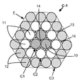
도 1은 현장에서 고무화되는 콤팩트한 유형의, 본 발명에 따른 3+9+15 구성의 코드를 단면으로 도시한다.
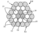
도 2는 현장에서 고무화되지 않는 유사하게 콤팩트한 유형인, 3+9+15 구성의 종래의 코드를 단면으로 도시한다.
도 3은 현장에서 고무화되는 원통형 층을 갖는 유형의, 본 발명에 따른 3+9+15 구성의 코드를 단면으로 도시한다.
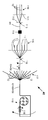
도 4는 본 발명에 따른 콤팩트한 구성의 코드를 제조하기 위해 사용될 수 있는 현장 고무화 및 꼬임 설비의 일례를 도시한다.
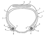
도 5는 이러한 일반화된 도면에서 본 발명에 따르거나 그렇지 않을 수 있는 래디얼 카커스 보강재를 구비한 중량 적재물 차량 타이어 케이싱을 방사상 단면으로 도시한다.1 shows, in cross section, a cord of the 3 + 9 + 15 configuration according to the invention of a compact type that is rubberized in the field.
Figure 2 shows in cross section a conventional cord of a 3 + 9 + 15 configuration, a similarly compact type that is not rubberized in the field.
3 shows in cross section a cord of the 3 + 9 + 15 configuration according to the invention, of the type having a cylindrical layer that is rubberized in the field.
4 shows an example of an in situ rubberization and twisting plant that can be used to produce a cord of compact configuration according to the invention.
FIG. 5 shows a radial load vehicle tire casing with a radial carcass reinforcement that may or may not be in accordance with the present invention in this generalized view.
Ⅰ. 측정 및 시험Ⅰ. Measure and test
Ⅰ-1. 동력 측정Ⅰ-1. Power measurement
금속 와이어 및 코드에 관해, Fm으로 표시되는 파단 강도(N 단위의 최대 하중), Rm으로 표시되는 (MPa 단위의) 인장 강도 및 At로 표시되는 파단시 신장율(% 단위의 총 신장율)의 측정이 1984년의 ISO 6892 표준에 따라 인장 시에 수행된다.For metal wires and cords, measurements of breaking strength (maximum load in N), tensile strength (in MPa), and elongation at break (in% total elongation) in At It is carried out at tension according to the ISO 6892 standard of 1984.
디엔 고무 조성물에 관해, 계수 측정이 달리 표시되지 않으면, 1998년의 ASTM D 412 표준(시편 "C")에 따라 인장 하에서 수행된다: E10으로 표시되며 MPa 단위로 표현되는 10% 신장율에서의 "진(true)" 시컨트 계수 (즉, 시편의 실제 단면에 대한 계수)가 제2 신장 시에 (즉, 1회 수용 사이클 후에) 측정된다 (1999년의 ASTM D 1349 표준에 따른 정상 온도 및 습도 조건).For diene rubber compositions, unless otherwise indicated, modulus measurements are performed under tension in accordance with the ASTM D 412 standard (Sample “C”) of 1998: “True” at 10% elongation, expressed in MPa. (true) "secant coefficient (ie, coefficient for the actual cross section of the specimen) is measured at the second elongation (ie after one acceptance cycle) (normal temperature and humidity conditions according to ASTM D 1349 standard of 1999) .
Ⅰ-2. 공기 투과성 시험I-2. Air permeability test
본 시험은 주어진 시간에 걸쳐 일정 압력 하에서 시편을 통과하는 공기의 체적을 측정함으로써 피시험 코드의 종방향 공기 투과성이 결정되는 것을 가능케 한다. 본 기술 분야의 당업자에게 공지된 그러한 시험의 원리는 코드를 공기에 대해 불투과성으로 만들기 위한 코드의 처리의 유효성을 입증하는 것이다. 시험은, 예를 들어, ASTM D2692-98 표준에 설명되어 있다.This test makes it possible to determine the longitudinal air permeability of the cord under test by measuring the volume of air passing through the specimen under constant pressure over a given time. The principle of such testing known to those skilled in the art is to demonstrate the effectiveness of the treatment of the cord to make the cord impermeable to air. Tests are described, for example, in the ASTM D2692-98 standard.
시험은 경화 고무로 외부로부터 이미 코팅된, 코드가 보강하는 타이어 또는 고무 플라이로부터 추출된 코드 상에서, 또는 이후에 코팅되고 경화되는 제조 시의 코드 상에서 수행된다.The test is carried out on cords extracted from tires or rubber plies that the cords reinforce, already coated from the outside with cured rubber, or on cords in the manufacture that are subsequently coated and cured.
후자의 경우에, 제조 시의 코드는 시험 이전에, 코팅 고무로서 공지된 고무에 의해 외부로부터 코팅되어야 한다. 이렇게 하기 위해, (20 mm의 코드간 거리로) 서로에 대해 평행하게 배열된 일련의 10개의 코드가 미경화 고무 조성물의 2개의 피막(80 x 200 mm로 측정되는 2개의 직사각형) 사이에 위치되고, 각각의 피막은 3.5 mm의 두께를 갖고; 전체 조립체는 그 다음 주형 내에 클램핑되고, 각각의 코드는 클램핑 모듈을 사용하여, 주형 내에 위치되는 동안 직선으로 유지되도록 보장하기 위해 충분한 인장(예를 들어, 2 daN) 하에서 유지되고; 가황 (경화) 공정이 그 다음 140℃의 온도에서 (80 x 200 mm로 측정되는 직사각형 피스톤에 의해 인가되는) 15 바아의 압력 하에서 40분에 걸쳐 발생한다. 그 후에, 조립체는 특성 해석을 위해, 탈형되어 적절한 치수(예컨대, 7x7x20 또는 7x7x30 mm)의 평행 6면체 형태로, 이렇게 코팅된 코드의 10개의 시편으로 절단된다.In the latter case, the cord at the time of manufacture must be coated from the outside with a rubber known as coating rubber before testing. To do this, a series of ten cords arranged parallel to each other (with a distance between cords of 20 mm) are placed between two coatings of the uncured rubber composition (two rectangles measuring 80 x 200 mm) and Each coating has a thickness of 3.5 mm; The entire assembly is then clamped in the mold, and each cord is maintained under sufficient tension (eg, 2 daN) to ensure that it is kept straight while being placed in the mold using the clamping module; The vulcanization (curing) process then takes place over 40 minutes at a temperature of 140 ° C. under a pressure of 15 bar (applied by a rectangular piston measuring 80 × 200 mm). Thereafter, the assembly is demoulded and cut into ten specimens of this coated cord in parallel hexagonal form of appropriate dimensions (eg, 7 × 7 × 20 or 7 × 7 × 30 mm) for characterization.
종래의 타이어 고무 조성물은 코팅 고무로서 사용되고, 상기 조성물은 천연(착해된) 고무 및 N330 카본 블랙(60 phr)에 기초하며, 또한 다음의 보통의 첨가제를 함유하고: 황(7 phr), 설펜아미드 가속화제(1 phr), ZnO(8 phr), 스테아르산(0.7 phr), 항산화제(1.5 phr), 및 코발트 나프테네이트(1.5 phr)(phr은 고무의 100부당 중량 부를 표시함); 코팅 고무의 계수(E10)는 약 10 MPa이다.Conventional tire rubber compositions are used as coating rubbers, which are based on natural (grafted) rubber and N330 carbon black (60 phr) and also contain the following common additives: sulfur (7 phr), sulfenamide Accelerator (1 phr), ZnO (8 phr), stearic acid (0.7 phr), antioxidant (1.5 phr), and cobalt naphthenate (1.5 phr) (phr indicates parts by weight per 100 parts of rubber); The coefficient E10 of the coated rubber is about 10 MPa.
시험은 다음과 같이, 경화 상태의 주변 고무 조성물 (또는 코팅 고무)로 코팅된 코드의 소정의 (예컨대, 3 cm 또는 2 cm) 길이 상에서 수행된다: 1 바아의 압력 하의 공기가 코드의 입구 내로 주입되고, 코드를 떠나는 공기의 체적이 (예를 들어, 0 내지 500 cm3/min으로 보정된) 유량계를 사용하여 측정된다. 측정 중에, 코드 시편은 코드의 종축을 따라 일 단부로부터 타 단부로 코드를 통과하는 공기의 양만이 측정되도록 압축된 기밀 시일(예를 들어, 조밀한 발포체 또는 고무 시일) 내에 고정되고; 기밀 시일의 기밀성은 중실 고무 시편, 즉 코드를 포함하지 않는 것을 사용하여 미리 점검된다.The test is carried out on a predetermined (eg 3 cm or 2 cm) length of cord coated with the surrounding rubber composition (or coated rubber) in a cured state, as follows: air under 1 bar of pressure is injected into the inlet of the cord And the volume of air leaving the cord is measured using a flow meter (e.g., calibrated to 0-500 cm 3 / min). During the measurement, the cord specimen is secured in a hermetic seal (eg, a dense foam or rubber seal) such that only the amount of air passing through the cord from one end to the other along the longitudinal axis of the cord is measured; The airtightness of the airtight seal is checked in advance using solid rubber specimens, i.e. those which do not contain cords.
코드의 종방향 불투과성이 높을수록, 측정된 평균 공기 유량(10개의 시편에 대한 평균)은 더 낮다. 측정이 ± 0.2 cm3/min으로 정확하므로, 0.2 cm3/min 이하의 측정치는 0으로 간주되고; 이는 코드의 종축을 따라 (즉, 코드의 종방향으로) 기밀(완전 기밀)인 것으로 지칭될 수 있는 코드에 대응한다.The higher the longitudinal impermeability of the cord, the lower the measured average air flow rate (average for 10 specimens). Since the measurement is accurate to ± 0.2 cm 3 / min, measurements below 0.2 cm 3 / min are considered 0; This corresponds to a code that may be referred to as confidential (fully confidential) along the longitudinal axis of the code (ie, in the longitudinal direction of the code).
Ⅰ-3. 충전 고무 함량Ⅰ-3. Filling rubber content
충전 고무의 양은 초기 코드(현장 고무화 코드)의 중량과 충전 고무가 적절한 전해 처리를 사용하여 제거된 코드 (및 그의 와이어)의 중량 사이의 차이를 측정함으로써 측정된다.The amount of filler rubber is measured by measuring the difference between the weight of the initial cord (field rubberized cord) and the weight of cord (and its wire) from which the filler rubber was removed using an appropriate electrolytic treatment.
크기를 감소시키기 위해 자체적으로 코일링된 코드 시편(1 m 길이)이 (발전기의 음극 단자에 연결된) 전해조의 음극을 구성하고, (양극 단자에 연결된) 양극은 백금 와이어로 구성된다.To reduce size, a coil piece of cord (1 m long) that is coiled itself constitutes the cathode of the electrolytic cell (connected to the negative terminal of the generator), and the anode (connected to the positive terminal) consists of platinum wire.
전해질은 1 리터의 탄산나트륨당 1 몰을 함유하는 수용액(탈이온수)으로 구성된다.The electrolyte consists of an aqueous solution (deionized water) containing 1 mol per 1 liter of sodium carbonate.
전해질 내에 완전히 침지된 시편은 300 mA의 전류에서 15분 동안 그에 인가되는 전압을 갖는다. 코드는 그 다음 전해조로부터 제거되고, 물로 충분히 헹궈진다. 이러한 처리는 고무가 코드로부터 쉽게 탈착되는 것을 가능케 한다 (그렇지 않다면, 전해가 수분 동안 계속된다). 고무는, 예를 들어 코드로부터 와이어를 하나씩 풀면서, 흡수성 천을 사용하여 단순히 이를 문지름으로써 신중하게 제거된다. 와이어는 다시 한번 물로 헹궈지고, 그 다음 탈이온수(50%) 및 에탄올(50%)의 혼합물을 담은 비커 내에 침지되고; 비커는 10분 동안 초음파조 내에 침지된다. 모든 고무 흔적물이 이렇게 제거된 와이어는 비커로부터 제거되고, 질소 또는 공기의 스트림 내에서 건조되고, 마지막으로 칭량된다.The specimen fully immersed in the electrolyte has a voltage applied to it for 15 minutes at a current of 300 mA. The cord is then removed from the cell and rinsed thoroughly with water. This treatment allows the rubber to be easily detached from the cord (otherwise the electrolysis continues for a few minutes). The rubber is carefully removed by simply rubbing it, for example using an absorbent cloth, while unwinding the wire one by one from the cord. The wire is once again rinsed with water and then immersed in a beaker containing a mixture of deionized water (50%) and ethanol (50%); The beaker is immersed in the ultrasonic bath for 10 minutes. The wire from which all rubber traces have been removed is removed from the beaker, dried in a stream of nitrogen or air, and finally weighed.
이로부터, 10회 측정에 대해 (즉, 총 10 m의 코드에 대해) 평균화된 초기 코드의 g(그램)당 충전 고무의 mg(밀리그램)으로 표현되는, 코드의 충전 고무 함량이 계산에 의해 도출된다.From this, the filling rubber content of the cord is derived by calculation, expressed in mg (milligrams) of filling rubber per g (grams) of the initial cord averaged over ten measurements (ie for a total of 10 m codes). do.
Ⅱ. 본 발명의 상세한 설명II. DETAILED DESCRIPTION OF THE INVENTION
본 설명에서, 명확하게 달리 표시되지 않으면, 표시되는 모든 백분율(%)은 중량에 의한 백분율이다.In the present description, unless explicitly indicated otherwise, all percentages indicated are percentages by weight.
또한, "a와 b 사이"라는 표현에 의해 표시되는 값의 임의의 범위는 a 초과 b 미만까지 연장하는 (즉, 종점(a, b)을 제외한) 값의 범위를 나타내고, "a 내지 b"라는 표현에 의해 표시되는 값의 임의의 범위는 a에서 b까지 연장하는 (즉, 정확한 종점(a, b)을 포함하는) 값의 범위를 의미한다.In addition, any range of values represented by the expression "between a and b" represents a range of values extending beyond a but less than b (ie, excluding the end points a and b), and "a to b". Any range of values denoted by the expression " means a range of values extending from a to b (i.e. including the exact endpoints (a, b)).
Ⅱ-1. 본 발명의 코드II-1. Code of the invention
그러므로, 본 발명의 금속 코드는 3개의 동심 층을 포함한다:Therefore, the metal cord of the present invention comprises three concentric layers:
- 피치(p1)의 나선으로 함께 조립된, 직경(d1)의 3개의 와이어로 구성된 제1 층 또는 중심 층(C1);A first layer or center layer C1 consisting of three wires of diameter d 1 , assembled together in a spiral of pitch p 1 ;
- 제1 층 둘레에서 피치(p2)의 나선으로 조립된, 직경(d2)의 M개의 와이어를 포함하는 제2 층(C2);A second layer C2 comprising M wires of diameter d 2 assembled in a spiral of pitch p 2 around the first layer;
- 제2 층 둘레에서 피치(p3)의 나선으로 조립된, 직경(d3)의 N개의 와이어를 포함하는 제3 층(C3).A third layer C3 comprising N wires of diameter d 3 , assembled in a spiral of pitch p 3 around the second layer.
공지된 방식으로, 제1 및 제2의 조립된 층(C1+C2)은 최외층(C3)을 지지하는, 일반적으로 코드의 중심으로 불리는 것을 구성한다.In a known manner, the first and second assembled layers C1 + C2 constitute what is generally referred to as the center of the cord, which supports the outermost layer C3.
본 발명의 이러한 코드는 또한 다음의 특징을 갖는다 (d1, d2, d3, p1, p2, p3는 mm 단위로 표현됨):This code of the invention also has the following features (d 1 , d 2 , d 3 , p 1 , p 2 , p 3 are expressed in mm):
- 0.08 ≤ d1 ≤ 0.50;0.08 ≦ d 1 ≦ 0.50;
- 0.08 ≤ d2 ≤ 0.50;0.08 ≦ d 2 ≦ 0.50;
- 0.08 ≤ d3 ≤ 0.50;0.08 ≦ d 3 ≦ 0.50;
- 3 < p1 < 50;3 <p 1 <50;
- 6 < p2 < 50;6 <p 2 <50;
- 9 < p3 < 50;- 9 <p 3 <50;
- 코드의 임의의 3 cm 길이에 걸쳐, "충전 고무"로 불리는 고무 조성물이 제1 층(C1)의 3개의 와이어에 의해 한정된 중심 채널 내에 그리고 한편으로 제1 층(C1)의 3개의 와이어 및 제2 층(C2)의 M개의 와이어 및 다른 한편으로 제2 층(C2)의 M개의 와이어 및 제3 층(C3)의 N개의 와이어에 의해 한정된 각각의 모세관 내에 존재하고;Over any 3 cm of length of the cord, a rubber composition called "filling rubber" is in the center channel defined by the three wires of the first layer C1 and on the other hand three wires of the first layer C1 and In each capillary defined by M wires of the second layer C2 and M wires of the second layer C2 and N wires of the third layer C3 on the other hand;
- 코드 내의 충전 고무의 함량은 코드의 그램당 10 mg과 50 mg 사이에 포함된다.The content of filling rubber in the cord is comprised between 10 mg and 50 mg per gram of cord.
본 발명의 이러한 코드는 현장 고무화 코드로 지칭될 수 있고, 즉 이는 그의 실제 제조 시에 (그러므로 제조 시의 상태에서) 충전 고무로 내부로부터 고무화된다. 바꾸어 말하면, 제1 층(C1)의 3개의 와이어에 의해 한정된 중심 채널 또는 모세관, 그리고 제1 및 제2 층(C1, C2) 및 제2 및 제3 층(C2, C3)에 의해 한정되며 이들 사이에 위치된 각각의 모세관 또는 갭(이들 2개의 교환 가능한 용어들은 충전 고무의 부재 시에 비어 있는 공극 또는 공간을 표시함)은, 코드의 축을 따라, 적어도 부분적으로, 연속적으로, 또는 달리 충전 고무로 충전된다.Such cords of the present invention may be referred to as in situ rubberization cords, ie they are rubberized from the inside with filling rubber during their actual production (and therefore in the state of manufacture). In other words, the central channel or capillary tube defined by the three wires of the first layer C1 and the first and second layers C1 and C2 and the second and third layers C2 and C3, and these Each capillary or gap located between them (the two interchangeable terms indicate empty voids or spaces in the absence of filled rubber) is at least partially, continuously, or otherwise filled rubber along the axis of the cord Is charged.
바람직한 실시예에 따르면, 코드의 임의의 3 cm 길이 또는 더 바람직하게는 임의의 2 cm 길이에 걸쳐, 위에서 설명된 중심 채널 및 각각의 모세관 또는 갭은 적어도 하나의 고무의 플러그를 포함하고; 바꾸어 말하면 그리고 바람직하게는, (문단 Ⅰ-2에 따른) 공기 투과성 시험에서, 본 발명의 이러한 코드가 2 cm3/min 미만, 더 바람직하게는 0.2 cm3/min 미만, 또는 최대 0.2 cm3/min의 평균 공기 유량을 갖는 방식으로, 코드의 중심 모세관 또는 채널 및 각각의 다른 모세관 또는 갭을 차단하는, 코드의 3 cm 또는 바람직하게는 2 cm마다 적어도 하나의 고무의 플러그가 있다.According to a preferred embodiment, over any 3 cm length or more preferably any 2 cm length of the cord, the center channel and each capillary or gap described above comprises a plug of at least one rubber; In other words and preferably, in the air permeability test (according to paragraph I-2), this cord of the invention is less than 2 cm 3 / min, more preferably less than 0.2 cm 3 / min, or at most 0.2 cm 3 / In a manner with an average air flow rate of min, there is a plug of at least one rubber every 3 cm or preferably 2 cm of the cord, blocking the central capillary or channel of the cord and each other capillary or gap.
본 발명의 코드의 다른 본질적인 특징은 그의 충전 고무 함량이 코드의 g당 10 mg과 50 mg 사이에 포함되는 것이다. 표시된 최소치 아래에서, 코드의 임의의 3 cm, 바람직하게는 2 cm 길이에 걸쳐, 충전 고무가 바람직하게는 적어도 하나의 플러그를 형성하도록 코드의 각각의 갭 또는 모세관 내에 적어도 부분적으로 정확하게 존재할 것을 보장하는 것이 불가능하고, 표시된 최대치 위에서, 코드는 코드의 주연부에서의 충전 고무의 넘침으로 인한 위에서 설명된 다양한 문제점에 노출된다. 모든 이러한 이유로, 충전 고무 함량이 코드의 g당 15 mg과 45 mg 사이, 더 바람직하게는 15 mg과 40 mg 사이에 포함되는 것이 바람직하다.Another essential feature of the cord of the present invention is that its filler rubber content is comprised between 10 mg and 50 mg per gram of cord. Below the indicated minimum, over any 3 cm, preferably 2 cm, length of the cord, to ensure that the filling rubber is present at least partially correctly within each gap or capillary of the cord to form at least one plug. It is not possible and above the indicated maximums, the cord is exposed to the various problems described above due to overflow of filling rubber at the periphery of the cord. For all these reasons, it is preferred that the filler rubber content be comprised between 15 mg and 45 mg per gram of cord, more preferably between 15 mg and 40 mg.
그러한 충전 고무 함량 및 이를 위에서 한정된 한도 내로 유지하는 것은 코드의 기하학적 형상에 적합하며 이후에 상세하게 설명될 특수한 꼬임-고무화 공정의 사용에 의해서만 가능해진다.Such filling rubber content and keeping it within the limits defined above is only possible by the use of a special twist-rubberizing process suitable for the geometry of the cord and described in detail later.
이러한 특수한 공정의 사용은, 동시에 충전 고무의 양이 제어되는 코드를 얻는 것을 가능케 하면서, (코드의 축을 따라 연속적이거나 불연속적인) 내부 격벽 또는 고무의 플러그가 본 발명의 코드의 모세관 내에 충분한 개수로 존재하도록 보장하고; 따라서, 본 발명의 코드는 물 또는 공기 중의 산소와 같은 임의의 부식성 유체의 코드를 따른 확산에 영향을 받지 않게 되어, 본 문헌의 도입부에서 설명된 흡상 효과를 제거한다.The use of this particular process allows for obtaining a cord in which the amount of filling rubber is simultaneously controlled, while a sufficient number of internal bulkheads or plugs of rubber (continuous or discontinuous along the axis of the cord) are present in a sufficient number in the capillary of the cord of the present invention. To ensure that; Thus, the cord of the present invention is not affected by the diffusion along the cord of any corrosive fluid, such as oxygen in water or air, thereby eliminating the wicking effect described in the introduction of this document.
따라서, 다음의 특징이 바람직하게는 만족된다: 코드의 임의의 3 cm, 바람직하게는 2 cm 길이에 걸쳐, 코드는 종방향으로 기밀성이거나 사실상 기밀성이다. 바꾸어 말하면, 코드의 각각의 모세관은 바람직하게는 상기 코드가 (고무와 같은 중합체로 외부로부터 코팅되면) 그의 종방향으로 기밀성이거나 사실상 기밀성이도록 이러한 주어진 길이에 걸쳐 적어도 하나의 충전 고무의 플러그 (또는 내부 격벽)을 포함한다.Thus, the following features are preferably satisfied: Over any 3 cm, preferably 2 cm, length of the cord, the cord is longitudinally or substantially airtight in the longitudinal direction. In other words, each capillary of the cord is preferably a plug (or internal) of at least one filling rubber over this given length such that the cord is hermetically or substantially airtight in its longitudinal direction (if coated from the outside with a polymer such as rubber). Bulkhead).
문단 Ⅰ-2에서 설명된 공기 투과성 시험에서, 종방향으로 "기밀성"이라고 하는 코드는 0.2 cm3/min 미만 또는 최대로 그와 동일한 평균 공기 유량을 특징으로 하고, 종방향으로 "사실상 기밀성"이라고 하는 코드는 2 cm3/min 미만, 바람직하게는 1 cm3/min 미만의 평균 공기 유량을 특징으로 한다.In the air permeability test described in paragraph I-2, the code called "confidential" in the longitudinal direction is characterized by an average air flow rate of less than or equal to 0.2 cm 3 / min and is referred to as "virtually airtight" in the longitudinal direction. The cord is characterized by an average air flow rate of less than 2 cm 3 / min, preferably less than 1 cm 3 / min.
코드의 강도, 구현성, 강성, 및 굴곡 내구성 사이의 최적화된 절충을 위해, 층(C1, C2, C3) 내의 와이어의 직경이, 이러한 와이어들이 층들 사이에서 동일한 직경을 갖든지 또는 갖지 않든지 간에, 다음의 관계를 만족시키는 것이 바람직하다 (d1, d2, d3는 mm 단위로 표현됨):For optimized compromise between the strength, implementability, stiffness, and flex durability of the cords, the diameters of the wires in layers C1, C2, C3, whether or not these wires have the same diameter between the layers, It is desirable to satisfy the following relationship (d 1 , d 2 , d 3 expressed in mm):
- 0.10 ≤ d1 ≤ 0.40;0.10 ≦ d 1 ≦ 0.40;
- 0.10 ≤ d2 ≤ 0.40;0.10 ≦ d 2 ≦ 0.40;
- 0.10 ≤ d3 ≤ 0.40.0.10 ≦ d 3 ≦ 0.40.
훨씬 더 바람직하게는, 다음의 관계가 만족된다:Even more preferably, the following relationship is satisfied:
- 0.10 ≤ d1 ≤ 0.30;0.10 ≦ d 1 ≦ 0.30;
- 0.10 ≤ d2 ≤ 0.30;0.10 ≦ d 2 ≦ 0.30;
- 0.10 ≤ d3 ≤ 0.30.0.10 ≦ d 3 ≦ 0.30.
층(C1, C2, C3) 내의 와이어들은 층들 사이에서 동일한 직경 또는 상이한 직경을 가질 수 있고; 바람직하게는 층들 사이에서 동일한 직경의 와이어가 제조를 현저하게 단순화하고 코드의 비용을 절감하므로, 사용된다 (즉, d1 = d2 = d3).The wires in layers C1, C2, C3 may have the same diameter or different diameters between the layers; Preferably, wires of the same diameter between the layers are used since they significantly simplify the manufacture and reduce the cost of the cord (ie d 1 = d 2 = d 3 ).
피치(p2, p3)는 더 바람직하게는 특히 d2 = d3일 때, 8 내지 25 mm의 범위, 훨씬 더 바람직하게는 10 내지 20 mm의 범위 내에서 선택된다.The pitches p 2 , p 3 are more preferably selected in the range of 8 to 25 mm, even more preferably in the range of 10 to 20 mm, especially when d 2 = d 3 .
다른 바람직한 실시예에 따르면, p2와 p3는 동일하고, 피치(p1)가 p2와 동일하거나 상이한 것이 가능하다. 다른 가능한 실시예에 따르면, p1 = p2 ≠ p3 또는 대안적으로 p1 ≠ p2 ≠ p3이다.According to another preferred embodiment, p 2 and p 3 are the same and it is possible for the pitch p 1 to be the same or different than p 2 . According to another possible embodiment p 1 = p 2 ≠ p 3 or alternatively p 1 ≠ p 2 ≠ p 3 .
다른 바람직한 실시예에 따르면, 코드 강도와 가요성 사이의 더 양호한 절충을 위해, 다음의 특징이 만족된다:According to another preferred embodiment, for a better compromise between cord strength and flexibility, the following features are satisfied:
- 3 < p1 < 30;3 <p 1 <30;
- 6 < p2 < 30;6 <p 2 <30;
- 9 < p3 < 30.9 <p 3 <30.
공지된 바와 같이, 피치("p")는 코드의 축에 대해 평행하게 측정된 길이를 나타내고, 코드의 단부에서, 이러한 피치의 와이어는 코드의 상기 축 둘레에서 완전한 회전을 이룬다는 것이 본 명세서에서 상기될 것이다.As is known, the pitch "p" refers to the length measured parallel to the axis of the cord, and at the end of the cord, it is herein understood that the wire of this pitch makes a complete rotation around the axis of the cord. It will be recalled.
하나의 특정 실시예에 따르면, 3개의 피치(p1, p2, p3)는 동일하다. 이는 특히 3개의 층(C1, C2, C3)이 동일한 꼬임 방향(S/S/S 또는 Z/Z/Z)으로 권취되는 추가의 특징을 갖는, 예를 들어 도 1에 개략적으로 도시된 것과 유사한 콤팩트한 유형의 층상화된 코드의 경우이다. 그러한 콤팩트한 층상화된 코드에서, 콤팩트함은 실질적으로 와이어의 구분된 층이 보이지 않도록 되어 있고; 이것이 의미하는 것은 그러한 코드의 단면이 도 1(본 발명에 따른 콤팩트 3+9+15 코드) 또는 도 2(대조구 콤팩트 3+9+15 코드, 즉 현장에서 고무화되지 않은 것)에 예시적으로 도시되어 있는 바와 같이, 원통형이 아닌 다각형인 외형을 갖는 것을 의미한다.According to one particular embodiment, the three pitches p 1 , p 2 , p 3 are identical. This in particular has the additional feature that the three layers C1, C2, C3 are wound in the same twisting direction (S / S / S or Z / Z / Z), for example similar to that schematically shown in FIG. 1. This is the case for compact types of layered code. In such compact layered cords, compactness is such that substantially no distinct layer of wire is visible; This means that the cross section of such a cord is exemplified in FIG. 1 (compact 3 + 9 + 15 cord according to the invention) or in FIG. 2 (control compact 3 + 9 + 15 cord, ie not rubberized in the field). As shown, it means having a contour that is polygonal rather than cylindrical.
제3 층 또는 외층(C3)은 포화 층의 바람직한 특징을 갖고, 즉 정의에 따르면, 직경(d3)의 적어도 하나의 (Nmax+1)번째 와이어가 추가되기 위한 이러한 층 내의 충분한 공간이 없고, Nmax는 제2 층(C2) 둘레의 층 내에 권취될 수 있는 와이어의 최대 개수를 나타낸다. 이러한 구성은 주연부에서의 충전 고무의 넘침의 위험을 추가로 제한하며, 주어진 코드 직경에 대해 더 큰 강도를 제공하는 뚜렷한 장점을 갖는다.The third layer or outer layer C3 has the desirable characteristics of a saturated layer, ie by definition there is not enough space in this layer for the addition of at least one (N max +1) th wire of diameter d 3 . , N max represents the maximum number of wires that can be wound in a layer around the second layer C2. This configuration further limits the risk of overfilling of the filled rubber at the perimeter and has the distinct advantage of providing greater strength for a given cord diameter.
그러나, 본 발명은 또한 외층(C3)이 불포화 층인 경우에 적용된다.However, the invention also applies when the outer layer (C3) is an unsaturated layer.
따라서, 와이어의 개수(N)는 본 발명의 특정 실시예에 따르면 매우 큰 범위로 변할 수 있고, 와이어(N)의 최대 개수(Nmax)는 바람직하게는 외층을 포화 상태로 유지하기 위해, 그의 직경(d3)이 제2 층의 와이어의 직경(d2)과 비교하여 감소되면, 증가될 것임이 이해된다.Thus, the number N of wires can vary in a very large range in accordance with certain embodiments of the invention, and the maximum number N max of wires N is preferably in order to keep the outer layer saturated. If the diameter (d 3) is reduced as compared to the diameter of the wire (d 2) of the second layer, it is understood this will be increased.
바람직한 실시예에 따르면, 제2 층(C2)은 6 내지 12개의 와이어를 포함하고, 제3 층(C3)은 12 내지 18개의 와이어를 포함하고; 전술한 코드 중에서, 더 특별히 선택된 것은 층(C2)과 층(C3) 사이에서 실질적으로 동일한 직경을 갖는 와이어로 구성된 것이다 (즉, d2 = d3).According to a preferred embodiment, the second layer C2 comprises 6 to 12 wires and the third layer C3 comprises 12 to 18 wires; Of the foregoing codes, more particularly selected ones consist of wires having substantially the same diameter between layers C2 and C3 (ie d 2 = d 3 ).
더 특별하게 바람직한 실시예에 따르면, 제2 층(C2)은 8 또는 9개의 와이어를 포함하고 (즉, M은 8 또는 9와 동일하고), 제3 층(C3)은 14 또는 15개의 와이어를 포함한다 (즉, N은 14 또는 15와 동일하다). 본 발명의 코드는 3+8+14 및 3+9+15의 특히 우선적인 구성을 갖는다.According to a more particularly preferred embodiment, the second layer C2 comprises 8 or 9 wires (ie M is equal to 8 or 9) and the third layer C3 comprises 14 or 15 wires. (Ie, N is equal to 14 or 15). The code of the present invention has a particularly preferred configuration of 3 + 8 + 14 and 3 + 9 + 15.
본 발명의 코드는 임의의 층상화된 코드와 유사하게, 2가지 유형, 즉 콤팩트한 층 유형 또는 원통형 층 유형일 수 있다.The cord of the present invention can be of two types, compact layer type or cylindrical layer type, similar to any layered cord.
바람직하게는, 3개의 층(C1, C2, C3)은 동일한 꼬임 방향, 즉 S 방향("S/S/S" 배열) 또는 Z 방향("Z/Z/Z" 배열)으로 권취된다. 이러한 층들을 동일한 방향으로 권취하는 것은 유리하게는 이러한 3개의 층들 사이의 마찰과, 층들이 구성되는 와이어들 상의 마모를 최소화한다. 더 바람직하게는, 이들은 예를 들어 도 1에 도시된 것과 유사한 콤팩트한 유형의 코드를 얻기 위해 동일한 꼬임 방향 및 동일한 피치(즉, p1 = p2 = p3)로 권취된다.Preferably, the three layers C1, C2, C3 are wound in the same twisting direction, ie in the S direction ("S / S / S" arrangement) or in the Z direction ("Z / Z / Z" arrangement). Winding these layers in the same direction advantageously minimizes friction between these three layers and wear on the wires on which the layers are composed. More preferably, they are wound in the same twisting direction and the same pitch (ie p 1 = p 2 = p 3 ) to obtain a compact type of cord similar to that shown for example in FIG. 1.
본 발명의 코드의 구성은 유리하게는 랩핑 와이어가 생략되는 것을 허용하고, 이는 고무가 그의 구조를 더 양호하게 침투하고 자가 랩핑 효과를 주기 때문이다.The construction of the cord of the invention advantageously allows the wrapping wire to be omitted, since the rubber penetrates its structure better and gives a self lapping effect.
"금속 코드"라는 용어는 본 출원에서의 정의에 따르면, 금속 재료로 주로 (즉, 이러한 와이어의 개수의 50% 초과) 또는 전체적으로 (100%의 와이어) 구성된 와이어로부터 형성된 코드를 의미하는 것으로 이해된다.The term "metal cord", according to the definition in this application, is understood to mean a cord formed from a wire composed primarily of metal material (ie, greater than 50% of the number of such wires) or wholly (100% wire). .
서로 독립적으로 그리고 층들 마다, 중심 층(C1)의 와이어 또는 와이어들, 제2 층(C2)의 와이어들, 및 제3 층(C3)의 와이어들은 바람직하게는 강철, 더 바람직하게는 탄소강으로 만들어진다. 그러나, 당연히 다른 강철, 예를 들어 스테인리스강, 또는 다른 합금을 사용하는 것이 가능하다.Independently of each other and per layer, the wires or wires of the central layer C1, the wires of the second layer C2, and the wires of the third layer C3 are preferably made of steel, more preferably carbon steel . However, it is of course possible to use other steels, for example stainless steel, or other alloys.
탄소강이 사용될 때, 그의 탄소 함량(강의 중량%)은 바람직하게는 0.4%와 1.2% 사이, 특히 0.5%와 1.1% 사이에 포함되고; 이러한 함량은 타이어에 대해 요구되는 기계적 특성과 와이어의 구현성 사이의 양호한 절충을 제시한다. 0.5%와 0.6% 사이에 포함된 탄소 함량은 궁극적으로 그러한 강철을, 인발하기가 더 쉽게 때문에, 저렴하게 만든다는 것을 알아야 한다. 본 발명의 다른 유리한 실시예는 또한 의도된 용도에 의존하여, 특히 더 낮은 비용 및 더 큰 인발성 때문에, 예를 들어 0.2%와 0.5% 사이에 포함된 낮은 탄소 함량을 갖는 강을 사용하는 것일 수 있다.When carbon steel is used, its carbon content (% by weight of steel) is preferably comprised between 0.4% and 1.2%, in particular between 0.5% and 1.1%; This content suggests a good compromise between the mechanical properties required for the tire and the implementability of the wire. It should be noted that the carbon content comprised between 0.5% and 0.6% ultimately makes such steels cheaper because they are easier to draw. Another advantageous embodiment of the invention may also be to use a steel having a low carbon content comprised between 0.2% and 0.5%, depending on the intended use, in particular because of its lower cost and greater pullability. have.
사용되는 금속 또는 강은 특히 이것이 탄소강이든지 또는 스테인리스강이든지 간에, 자체가 예를 들어 금속 코드 및/또는 그의 구성 요소의 작업성, 또는 접착, 부식 저항 또는 노후화에 대한 저항의 특성과 같은, 코드 및/또는 타이어 자체의 사용 특성을 개선하는 금속 층으로 코팅될 수 있다. 하나의 바람직한 실시예에 따르면, 사용되는 강은 황동(Zn-Cu 합금) 또는 아연의 층으로 덮이고; 와이어 제조 공정 중에, 황동 또는 아연 코팅은 와이어를 인발하기 더 쉽게 만들고, 와이어를 고무에 더 양호하게 접착하게 만드는 것이 상기될 것이다. 그러나, 와이어는, 예를 들어, 이러한 와이어의 부식 저항 및/또는 고무에 대한 그의 접착을 개선하는 기능을 갖는 황동 또는 아연 이외의 금속의 얇은 층, 예를 들어 Co, Ni, Al, 및 Cu, Zn, Al, Ni, Co, Sn 화합물 중 둘 이상의 합금의 얇은 층으로 덮일 수 있다.The metal or steel used, in particular whether it is carbon steel or stainless steel, is itself a cord, such as, for example, the workability of the metal cord and / or its components, or the properties of resistance to adhesion, corrosion resistance or aging. And / or coated with a metal layer that improves the use characteristics of the tire itself. According to one preferred embodiment, the steel used is covered with a layer of brass (Zn-Cu alloy) or zinc; During the wire manufacturing process, it will be recalled that the brass or zinc coating makes the wire easier to draw and makes the wire better adhere to the rubber. However, the wire may be, for example, a thin layer of metal other than brass or zinc, such as Co, Ni, Al, and Cu, having the function of improving the corrosion resistance of such wire and / or its adhesion to rubber. It may be covered with a thin layer of two or more alloys of Zn, Al, Ni, Co, Sn compounds.
본 발명의 코드는 바람직하게는 탄소강으로 만들어지고, 바람직하게는 2500 MPa 초과, 더 바람직하게는 3000 MPa 초과의 인장 강도(Rm)를 갖는다. 그의 구조, 탄성, 및 소성 신장율의 합인, 코드의 파단 시의 총 신장율(At)은 바람직하게는 2.0% 초과, 훨씬 더 바람직하게는 적어도 2.5%이다.The cord of the present invention is preferably made of carbon steel and preferably has a tensile strength (Rm) of greater than 2500 MPa, more preferably greater than 3000 MPa. The total elongation at break (At) at break of the cord, which is the sum of its structure, elasticity, and plastic elongation, is preferably greater than 2.0%, even more preferably at least 2.5%.
충전 고무의 탄성중합체 (또는 동일하게 "고무", 이들 둘은 동의어로 간주됨)는 바람직하게는 디엔 탄성중합체, 즉 정의에 따르면 디엔 단량체(들)(즉, 2개의 공액 결합 또는 탄소-탄소 이중 결합을 보유하는 단량체(들))로부터 적어도 부분적으로 기원하는 탄성중합체(즉, 동종중합체 또는 공중합체)이다. 디엔 탄성중합체는 더 바람직하게는 폴리부타디엔(BR), 천연 고무(NR), 합성 폴리이소프렌(IR), 부타디엔의 다양한 공중합체, 이소프렌의 다양한 공중합체, 및 이들 탄성중합체의 블렌드로 구성된 그룹으로부터 선택된다. 그러한 공중합체는 더 바람직하게는 에멀전 중합(ESBR) 또는 용액 중합(SSBR)에 의해 준비되는 부타디엔-스티렌 공중합체(SBR), 부타디엔-이소프렌 공중합체(BIR), 스티렌-이소프렌 공중합체(SIR) 및 스티렌-부타디엔-이소프렌 공중합체(SBIR)로 구성된 그룹으로부터 선택된다.The elastomer (or equally "rubber", both of which are considered synonymous) of the filler rubber is preferably a diene elastomer, ie diene monomer (s) by definition (i.e. two conjugated bonds or carbon-carbon doubles) Elastomers (ie homopolymers or copolymers) originating at least partially from the monomer (s) bearing the bond). The diene elastomer is more preferably selected from the group consisting of polybutadiene (BR), natural rubber (NR), synthetic polyisoprene (IR), various copolymers of butadiene, various copolymers of isoprene, and blends of these elastomers do. Such copolymers are more preferably butadiene-styrene copolymers (SBR), butadiene-isoprene copolymers (BIR), styrene-isoprene copolymers (SIR) and are prepared by emulsion polymerization (ESBR) or solution polymerization (SSBR) and Styrene-butadiene-isoprene copolymer (SBIR).
하나의 바람직한 실시예는 "이소프렌" 탄성중합체, 즉 이소프렌의 동종중합체 또는 공중합체, 바꾸어 말하면 천연 고무(NR), 합성 폴리이소프렌(IR), 다양한 이소프렌 공중합체 및 이들 탄성중합체의 블렌드로 구성된 그룹으로부터 선택된 디엔 탄성중합체를 사용하는 것이다. 이이소프렌 탄성중합체는 바람직하게는 천연 고무 또는 시스-1,4 타입의 합성 폴리이소프렌이다. 이러한 합성 폴리이소프렌 중에서, 90% 초과, 훨씬 더 바람직하게는 98% 초과의 시스-1,4 결합의 함량(몰% 단위)을 갖는 폴리이소프렌이 사용된다. 다른 바람직한 실시예에 따르면, 이소프렌 탄성중합체는 또한, 예를 들어, SBR 및/또는 BR 타입 중 하나와 같은, 다른 디엔 탄성중합체와 조합될 수 있다.One preferred embodiment is from a group consisting of "isoprene" elastomers, ie homopolymers or copolymers of isoprene, in other words natural rubber (NR), synthetic polyisoprene (IR), various isoprene copolymers and blends of these elastomers It is to use the diene elastomer selected. Isoprene elastomers are preferably natural rubber or synthetic polyisoprene of the cis-1,4 type. Among these synthetic polyisoprene, polyisoprene is used having a content (in mole%) of cis-1,4 bonds of greater than 90%, even more preferably greater than 98%. According to another preferred embodiment, the isoprene elastomer can also be combined with other diene elastomers, such as for example one of the SBR and / or BR type.
충전 고무는 특히 디엔 타입의 단지 하나의 탄성중합체 또는 여러 탄성중합체를 함유할 수 있고, 이들이 탄성중합체 이외의 임의의 유형의 중합체와 조합하여 사용되는 것이 가능하다.Filling rubbers may contain in particular only one elastomer or several elastomers of the diene type, and it is possible for them to be used in combination with any type of polymer other than an elastomer.
충전 고무는 바람직하게는 가교 결합 가능한 타입이고, 즉 이는 정의에 따르면 조성물이 (즉, 그가 가열될 때, 용융되기보다는 경질화되도록) 그의 경화 공정 중에 가교 결합하도록 허용하기에 적합한 가교 결합계를 함유하고; 따라서, 그러한 경우에, 이러한 고무 조성물은 그가 어떤 온도에서도 가열에 의해 용융될 수 없기 때문에, 용융 불가능한 것으로 간주될 수 있다. 바람직하게는, 디엔 고무 조성물의 경우에, 고무 외피를 위한 가교 결합계는 가황계, 즉 황 (또는 황 공여체제) 및 적어도 하나의 가황 가속화제에 기초한 계로서 공지된 계이다. 다양한 공지된 가황 활성화제가 이러한 가황계에 첨가될 수 있다. 황은 0.5와 10 phr 사이, 더 바람직하게는 1과 8 phr 사이의 바람직한 함량으로 사용된다. 가황 가속화제, 예를 들어 설펜아미드는 0.5와 10 phr 사이, 더 바람직하게는 0.5와 5.0 phr 사이의 바람직한 함량으로 사용된다.The filler rubber is preferably of the crosslinkable type, ie it contains, by definition, a crosslinking system suitable to allow the composition to crosslink during its curing process (ie so that when it is heated, it hardens rather than melts). and; Thus, in such a case, such a rubber composition can be considered insoluble because it cannot be melted by heating at any temperature. Preferably, in the case of diene rubber compositions, the crosslinking system for the rubber sheath is a system known as a vulcanization system, ie a system based on sulfur (or sulfur donor agents) and at least one vulcanization accelerator. Various known vulcanization activators can be added to such vulcanization systems. Sulfur is used in a preferred content between 0.5 and 10 phr, more preferably between 1 and 8 phr. Vulcanization accelerators such as sulfenamides are used in preferred amounts between 0.5 and 10 phr, more preferably between 0.5 and 5.0 phr.
충전 고무는 또한 상기 가교 결합계에 추가하여, 카본 블랙과 같은 보강 충전제 또는 실리카와 같은 무기 충전제, 결합제, 노후화 방지제, 항산화제, 가소화제 또는 오일 연장제 - 예를 들어 높은 또는 바람직하게는 낮은 점성을 갖는 나프텐 또는 파라핀 타입의 방향족 또는 비방향족 타입, 특히 매우 약한 또는 비방향성 오일 -, MES 또는 TDAE 오일, 30℃ 위의 높은 Tg를 갖는 가소화 수지, 미경화 상태의 조성물을 가공하는 것을 더 쉽게 만들기 위한 가공 보조제, 점조화 수지, 역전 방지제, 예를 들어 HMT(헥사메틸렌 테트라아민) 또는 H3M(헥사메톡시메틸멜라민)과 같은 메틸렌 수용체 및 공여체, (레조시놀 또는 비스말레이미드와 같은) 보강 수지, 금속 염 타입, 예를 들어 특히 코발트 또는 니켈 염의 공지된 접착 증진계와 같은, 타이어의 제조를 위해 의도된 고무 매트릭스 내에서 일상적으로 사용되는 첨가제의 전부 또는 일부를 함유할 수 있다.Filling rubbers may also be used in addition to the crosslinking system, in addition to reinforcing fillers such as carbon black or inorganic fillers such as silica, binders, anti-aging agents, antioxidants, plasticizers or oil extenders-for example high or preferably low viscosity. For processing aromatic or non-aromatic types of naphthene or paraffin type, in particular very weak or non-aromatic oils, especially MES or TDAE oils, plasticizing resins with high Tg above 30 ° C., uncured compositions Processing aids, viscous resins, anti-reversal agents, for example, methylene acceptors and donors such as HMT (hexamethylene tetraamine) or H3M (hexamethoxymethylmelamine), (such as resorcinol or bismaleimide) Reinforced resins, metal salt types, for example, intended for the production of tires, such as known adhesion promoters of cobalt or nickel salts It may contain all or part of the additives commonly used in the rubber matrix.
보강 충전제, 예를 들어 카본 블랙 또는 실리카와 같은 무기 보강 충전제의 함량은 바람직하게는 50 phr 초과이고, 예를 들어 50과 120 phr 사이에 포함된다. 카본 블랙, 예를 들어 특히 (타이어 등급 블랙으로서 공지된) 타이어 내에서 종래에 사용되는 HAF, ISAF, SAF 타입의 모든 카본 블랙이 적합하다. 이 중에서, 더 특별하게는 (ASTM) 300, 600, 또는 700 등급의 카본 블랙이 언급될 수 있다 (예를 들어, N326, N330, N347, N375, N683, N772). 적합한 무기 보강 충전제는 특히 실리카(SiO2) 타입, 특히 450 m2/g 미만, 바람직하게는 30 내지 400 m2/g의 BET 표면적을 갖는 침전 또는 열분해 실리카를 포함한다.The content of reinforcing fillers, for example inorganic reinforcing fillers such as carbon black or silica, is preferably greater than 50 phr, for example comprised between 50 and 120 phr. Carbon blacks, for example all carbon blacks of the HAF, ISAF, SAF type conventionally used in tires (known as tire grade blacks) are suitable. Among these, more specifically, (ASTM) 300, 600, or 700 grade carbon black may be mentioned (eg N326, N330, N347, N375, N683, N772). Suitable inorganic reinforcing fillers include in particular silica (SiO 2 ) types, in particular precipitated or pyrolytic silicas having a BET surface area of less than 450 m 2 / g, preferably 30 to 400 m 2 / g.
본 기술 분야의 당업자는 본 설명에 비추어, 원하는 수준의 특성(특히, 탄성 계수)를 달성하기 위해 충전 고무의 배합을 조정하는 방법 및 의도된 특수한 용도에 적합하도록 배합을 맞추는 방법을 알 것이다.Those skilled in the art will, in light of the present description, know how to adjust the formulation of filler rubber to achieve the desired level of properties (particularly modulus of elasticity) and how to tailor the formulation to suit the particular application intended.
본 발명의 제1 실시예에서, 충전 고무의 배합은 본 발명의 코드가 보강하도록 의도된 고무 매트릭스의 배합과 동일하도록 선택될 수 있고; 그러므로 충전 고무 및 상기 고무 매트릭스의 각각의 재료 사이의 양립성의 문제점이 없을 것이다.In the first embodiment of the present invention, the formulation of the filling rubber can be selected to be the same as the formulation of the rubber matrix intended for the reinforcement of the cord of the present invention; Therefore, there will be no problem of compatibility between the fill rubber and each material of the rubber matrix.
본 발명의 제2 실시예에 따르면, 충전 고무의 배합은 본 발명의 코드가 보강하도록 의도된 고무 매트릭스의 배합과 상이하도록 선택될 수 있다. 특히, 충전 고무의 배합은 전형적으로 예를 들어 코발트 또는 니켈 염과 같은 금속 염의 5 내지 15 phr의 상대적으로 높은 양의 접착 증진제를 사용하고, 유리하게는 주변 고무 매트릭스 내의 상기 증진제의 양을 감소시키거나 (이를 모두 생략)함으로써, 조정될 수 있다. 당연히, 충전 고무의 점성과 코드가 제조될 때 코드를 침투하는 충전 고무의 능력을 최적화하기 위해, 충전 고무의 배합을 조정하는 것도 가능할 수 있다.According to a second embodiment of the invention, the formulation of the filler rubber can be chosen to be different from the formulation of the rubber matrix intended for the reinforcement of the cord of the invention. In particular, the formulation of the filler rubber typically uses a relatively high amount of adhesion promoter of 5 to 15 phr of metal salts such as, for example, cobalt or nickel salts, and advantageously reduces the amount of said promoter in the surrounding rubber matrix. Or by omitting them all. Naturally, it may also be possible to adjust the formulation of the filler rubber in order to optimize the viscosity of the filler rubber and the ability of the filler rubber to penetrate the cord when the cord is made.
바람직하게는, 가교 결합 상태의 충전 고무는 2와 25 MPa 사이, 더 바람직하게는 3과 20 MPa 사이에 포함되고, 특히 3과 15 MPa의 범위 내에 포함된 (10% 신장율에서의) 연장 시의 시컨트 계수(E10)를 갖는다.Preferably, the filled rubber in the crosslinked state is comprised between 2 and 25 MPa, more preferably between 3 and 20 MPa, in particular within the range of 3 and 15 MPa (at 10% elongation) Has secant coefficient E10.
본 발명은 당연히 미경화 상태(충전 고무가 가교 결합되지 않음) 및 경화 상태(충전 고무가 가교 결합되거나 가황됨)의 전술한 코드에 관한 것이다. 그러나, 최종 가교 결합 또는 가황 중에, 충전 고무와 주변의 고무 매트릭스(예를 들어, 캘린더링 고무) 사이의 결합을 촉진하기 위해, 본 발명의 코드가 그가 의도된 타이어와 같은 반마무리 제품 또는 마무리 제품 내로 이후에 통합될 때까지 미경화 상태의 충전 고무와 함께 사용되는 것이 바람직하다.The present invention naturally relates to the aforementioned cords in the uncured state (the filled rubber is not crosslinked) and in the cured state (the filled rubber is crosslinked or vulcanized). However, during the final crosslinking or vulcanization, in order to facilitate the bonding between the filling rubber and the surrounding rubber matrix (e.g. calendering rubber), the cords of the present invention are either semi-finished or finished products such as tires intended for them. It is preferably used with uncured filling rubber until it is subsequently incorporated into.
도 1은 본 발명에 따른 바람직한 3+9+15 코드의 일례를, (직선이며 고정된 것으로 가정된) 코드의 축에 대해 직교하는 단면으로 개략적으로 도시한다.1 schematically shows an example of a preferred 3 + 9 + 15 cord according to the invention in a cross section orthogonal to the axis of the cord (assumed to be straight and fixed).
이러한 코드(C-1으로 표시됨)는 콤팩트 유형이고, 즉 와이어의 그의 제1, 제2, 및 제3 층(각각 C1, C2, C3)이 동일한 방향(공지된 용어를 사용하기 위해 S/S/S 또는 Z/Z/Z)으로 권취되고, 또한 동일한 피치(p1 = p2 = p3)를 갖는다. 이러한 유형의 구성은 제2 및 제3 층(C2, C3)의 와이어(11, 12)들이 중심 층(C1)의 3개의 와이어(10) 둘레에서, 소위 원통형 층 유형의 코드의 경우에서와 같은 원통형이 아닌 실질적으로 다각형(더 구체적으로, 육각형)인 (점선으로 도시된) 외형(E)을 각각 갖는 2개의 실질적으로 동심인 층들을 형성하는 효과를 갖는다.This code (denoted C-1) is of a compact type, ie its first, second, and third layers (C1, C2, C3, respectively) in the same direction (S / S to use known terms) / S or Z / Z / Z) and also have the same pitch (p 1 = p 2 = p 3 ). This type of configuration is such that the
와이어들을 아주 약간 분리하면서, 충전 고무(13)가 제1 층(C1)의 3개의 와이어(10)에 의해 한정된 중심 채널 또는 모세관(14) 그리고 한편으로 제1 층(C1)의 3개의 와이어(10) 및 제2 층(C2)의 M개의 와이어(11) 및 다른 한편으로 제2 층(C2)의 M개의 와이어(11) 및 제3 층(C3)의 N개의 와이어(12)에 의해 한정된 각각의 모세관(15)(예시적으로, 이중 일부, 특히 최중심 모세관은 여기서 삼각형에 의해 표시됨)을 적어도 부분적으로 충전하는 것을 이러한 도 1로부터 알 수 있고, 와이어는 3 x 3으로 간주된다. 전체로, 36개의 모세관(15) 또는 갭이 중심 모세관(14)이 당연히 추가되어야 하는 3+9+15 코드의 이러한 예에서 존재하는 것을 여기서 알 수 있다.With very little separation of the wires, the filling
바람직한 실시예에 따르면, 본 발명에 따른 코드에서, 충전 고무는 그가 덮는 제2 층(C2) 둘레에서 연속적으로 연장한다.According to a preferred embodiment, in the cord according to the invention, the filling rubber extends continuously around the second layer C2 that it covers.
비교를 위해, 도 2는 종래의 3+9+15 코드(C-2로 표시됨), 즉 콤팩트한 유형과 유사한, 현장에서 고무화되지 않은 것의 잔여부를 단면으로 제공한다. 충전 고무의 부재는 실질적으로 모든 와이어(20, 21, 22)들이 서로 접촉하여, 특히 콤팩트하지만, 다른 한편으로 고무가 외부로부터 침투하기가 (불가능하다고 하지 못하더라도) 매우 어려운 구조로 이어지는 것을 의미한다. 이러한 유형의 코드의 특징은 다양한 3개씩의 와이어가 2개의 인접한 층들 사이에서, 대부분이 폐쇄되고 비어 있으며, 그러므로 "흡상" 효과를 통해, 물과 같은 부식 매체의 전파가 쉬운 채널 또는 모세관(25)을 형성하는 것이다.For comparison, FIG. 2 provides in cross section the remainder of a conventional 3 + 9 + 15 cord (denoted C-2), ie not rubberized in the field, similar to the compact type. The absence of filled rubber means that substantially all the
도 3은 제2 및 제3 층(C2, C3)의 와이어(각각 31, 32)가 중심 층(C1)의 3개의 와이어(30) 둘레에서, 실질적으로 원통형이며 앞서 도 1에서와 같은 육각형이 아닌 (점선으로 도시된) 외형(E)을 각각 갖는 2개의 실질적으로 동심인 층을 형성하는 것을 의미하는, 여기서 원통형 층을 구비한 유형의, 본 발명에 따른 바람직한 3+9+15 코드(C-3로 표시됨)의 다른 예를, (직선이며 고정된 것으로 가정된) 코어의 축에 대해 직교하는 단면으로 개략적으로 도시한다.3 shows that the
와이어들을 매우 약간 분할하는 충전 고무(33)는 제1 층(C1)의 3개의 와이어(30)에 의해 한정된 중심 채널(34) 그리고 한편으로 제1 층(C1)의 3개의 와이어(30) 및 제2 층(C2)의 M개의 와이어(31) 및 다른 한편으로 제2 층(C2)의 M개의 와이어(31) 및 제3 층(C3)의 N개의 와이어(32)에 의해 한정되고 이들 사이에 위치된 각각의 모세관 또는 갭(35)(예시적으로, 이중 일부, 특히 최중심 갭은 여기서 삼각형에 의해 표시됨)을 적어도 부분적으로 충전하는 것을 이러한 도 3으로부터 알 수 있고, 이러한 와이어들은 적어도 3개의 인접한 와이어들의 그룹으로 (이러한 특정 예에서, 도 3에 도시된 모세관 또는 갭의 예에 따르면, 3, 4, 5, 또는 6개의 와이어의 그룹으로) 간주된다.Filling
본 발명의 코드는, 예를 들어 외층(C3)보다 더 짧은 피치로 그리고 이러한 외층과 반대이거나 동일한 권취 방향으로 코드 둘레에서 나선으로 권취된 단일 금속 또는 비금속 스레드로 구성된 외부 랩퍼를 구비할 수 있다. 그러나, 그의 특수한 구조 때문에, 이미 자가 랩핑된 본 발명의 코드는 대체로 외측 랩핑 스레드의 사용을 요구하지 않고, 이는 유리하게는 랩퍼와 코드의 최외층의 와이어 사이의 마모의 문제점을 해결한다.The cord of the present invention may have an outer wrapper, for example, consisting of a single metal or nonmetallic thread wound spirally around the cord in a shorter pitch than the outer layer C3 and in the direction of winding opposite or the same as the outer layer. However, due to its special structure, the already self-wrapped cord of the invention generally does not require the use of an outer wrapping thread, which advantageously solves the problem of wear between the wrapper and the wire of the outermost layer of the cord.
그러나, 랩핑 스레드가 사용되면, 외층의 와이어가 탄소강으로 만들어지는 일반적인 경우에, 스테인리스강으로 만들어진 랩핑 스레드가, 예를 들어 국제 특허 출원 공개 WO-A-98/41682호에 개시된 바와 같이, 스테인리스강 랩퍼와의 접촉 시의 이러한 탄소강 와이어의 프렛팅 마모를 감소시키기 위해 유리하게 선택될 수 있고, 스테인리스강 와이어는 잠재적으로 유사하게, 예를 들어 EP-A-976 541호에 설명되어 있는 바와 같이, 표피는 스테인리스강으로 만들어지고 코어는 탄소강으로 만들어진 복합 스레드에 의해 대체된다. 국제 특허 출원 공개 WO-A-03/048447호에 설명되어 있는 바와 같이, 폴리에스터 또는 굴열성 방향족 폴리에스터-아미드로 만들어진 랩퍼를 사용하는 것도 가능하다.However, if a lapping thread is used, in the general case where the wire of the outer layer is made of carbon steel, a lapping thread made of stainless steel is made of stainless steel, for example, as disclosed in WO-A-98 / 41682. It can be advantageously chosen to reduce the freting wear of such carbon steel wires in contact with the wrapper, and the stainless steel wires are potentially similarly described, for example, in EP-A-976 541, The skin is made of stainless steel and the core is replaced by a composite thread made of carbon steel. As described in International Patent Application Publication No. WO-A-03 / 048447, it is also possible to use wrappers made of polyester or pyrogenic aromatic polyester-amides.
본 기술 분야의 당업자는 위에서 설명된 바와 같은 본 발명의 코드가 잠재적으로 디엔 탄성중합체 이외의 탄성중합체에 기초한 충전 고무, 특히 예를 들어 공지된 바와 같이 가교 결합 또는 가황을 요구하지 않지만, 사용 온도에서, 가황 디엔 탄성중합체와 유사한 특성을 보이는 폴리우레탄 탄성중합체(TPU)와 같은 열가소성 탄성중합체(TPE)로 현장에서 고무화될 수 있음을 이해할 것이다.Those skilled in the art will appreciate that the cords of the present invention as described above do not potentially require filling rubbers based on elastomers other than diene elastomers, in particular crosslinking or vulcanization, for example as known, It will be appreciated that thermoplastic elastomers (TPEs), such as polyurethane elastomers (TPUs), exhibit similar properties to vulcanized diene elastomers.
그러나, 특히 바람직하게는, 본 발명은 앞서 설명된 바와 같이 디엔 탄성중합체에 기초한 충전 고무를 사용하여, 특히 그러한 탄성중합체에 특히 적합한 특수한 제조 공정의 사용에 의해, 실시된다. 이러한 제조 공정은 이하에서 상세하게 설명된다.However, particularly preferably, the present invention is practiced using filler rubbers based on diene elastomers as described above, in particular by the use of special manufacturing processes which are particularly suitable for such elastomers. This manufacturing process is described in detail below.
Ⅱ-2. 본 발명의 코드의 제조II-2. Preparation of the Cord of the Invention
바람직하게는 디엔 탄성중합체를 사용하여 현장에서 고무화되는 본 발명의 전술한 코드는 바람직하게는 인라인으로(in-line) 연속적으로 수행되는 다음의 단계를 포함하는 공정을 사용하여 제조될 수 있다:The above-described cords of the invention, preferably rubberized in situ using diene elastomers, can be prepared using a process comprising the following steps, preferably carried out continuously in-line:
- "제1 조립 지점"으로 불리는 제1 지점에서, 제1 층 또는 중심 층(C1)을 형성하도록 중심 층의 3개의 와이어를 꼬아서 조립하는 제1 단계;At a first point, called a "first assembly point", a first step of twisting and assembling the three wires of the center layer to form a first layer or a center layer C1;
- "제2 조립 지점"으로 불리는 제2 지점에서, 3+M 구성의 "코어 스트랜드"로 불리는 중간 코드(C1+C2)를 형성하도록 중심 층(C1) 둘레에서 M개의 와이어를 꼬는 제2 조립 단계;A second assembly, twisting M wires around the center layer C1 to form an intermediate cord C1 + C2 called a "core strand" of 3 + M configuration, at a second point called the "second assembly point" step;
- 제1 조립 지점의 하류에서, 중심 층(C1) 및/또는 코어 스트랜드(C1+C2)가 미경화 상태의 충전 고무로 피복되는 피복 단계(이러한 피복은 제2 조립 지점의 상류 또는 하류, 또는 상류 및 하류에서 수행됨);Downstream of the first assembly point, the coating step in which the central layer C1 and / or the core strands C1 + C2 are covered with uncured filling rubber (the coating is upstream or downstream of the second assembly point, or Performed upstream and downstream);
- 이렇게 피복된 코어 스트랜드 둘레에서 N개의 와이어를 꼬거나 케이블링하는, 이어지는 제3 조립 단계;A subsequent third assembly step of twisting or cabling N wires around the core strand thus coated;
- 최종 꼬임-균형 단계.Final twist-balance step.
바람직하게는, 충전 고무로 피복하는 단계는 제1 조립 지점의 하류 및 제2 조립 지점의 상류에서, 중심 층(C1) 상에서만 수행되고, 충전 고무는 본 발명에 따른 코드를 얻기에 충분한 양의 단일 분출로 전달된다. 하나의 가능한 대안적인 실시예의 형태는 제2 조립 지점의 하류에서, 코어 스트랜드(C1+C2)를 피복하는 추가의 단계를 수행하는 것일 수 있다. 그러나, 단지 하나의 피복 단계를 수행하는 것이 바람직하다.Preferably, the step of coating with the filling rubber is carried out only on the central layer C1, downstream of the first assembly point and upstream of the second assembly point, the filling rubber being of sufficient amount to obtain a cord according to the invention. Delivered in a single ejection. One possible alternative embodiment form may be to perform an additional step of covering the core strand C1 + C2 downstream of the second assembly point. However, it is preferable to carry out only one coating step.
금속 와이어를 조립하기 위한 2가지 가능한 기술이 있음이 여기서 상기될 것이다:It will be recalled here that there are two possible techniques for assembling metal wires:
- 와이어가 조립 지점 이전 및 이후의 동기 회전 때문에, 그 자신의 축에 대한 꼬임을 겪지 않는 케이블링; 또는Cabling in which the wire does not suffer from twisting about its own axis due to synchronous rotation before and after the assembly point; or
- 와이어가 그 자신의 축에 대한 집합적 꼬임 및 개별적 꼬임을 겪어서, 각각의 와이어 및 코드 자체 상에서 풀림 토크를 발생시키는 꼬임.The wire undergoes collective twist and individual twist on its own axis, creating twisting torque on each wire and the cord itself.
상기 방법의 하나의 본질적인 특징은 제1 층(C1)의 와이어를 조립하고 중심 층(C1) 둘레에서 제2 층(C2)을 조립하기 위한 꼬임 단계의 사용이다.One essential feature of the method is the use of a twisting step to assemble the wire of the first layer C1 and to assemble the second layer C2 around the center layer C1.
제3 층(C3)은 꼬임 또는 케이블링에 의해 제2 층(C2) 둘레에서 조립될 수 있다. 처음 2개의 조립 작업(층(C1, C2))에 대해 꼬임 작업을 사용하는 것이 바람직하다.The third layer C3 may be assembled around the second layer C2 by twisting or cabling. It is preferable to use the twisting operation for the first two assembly operations (layers C1, C2).
제3 층(C3)이 케이블링에 의해 조립되면, 코드는 바람직하게는 2개의 불연속적인 단계(처음 2개의 층의 꼬임 및 그 다음 제3 층의 이후의 케이블링)에서 제조되고; 이러한 경우에, 2개의 피복 단계, 중심 층(C1)의 제1 피복 및 코어 스트랜드(C1+C2) 상에서의 이후의 제2 피복을 사용하는 것이 바람직하다.If the third layer C3 is assembled by cabling, the cord is preferably produced in two discontinuous steps (twisting of the first two layers and then subsequent cabling of the third layer); In this case, it is preferable to use two coating steps, the first coating of the center layer C1 and the subsequent second coating on the core strands C1 + C2.
예시적으로, 절차는 다음과 같다.By way of example, the procedure is as follows.
중심 층의 와이어들은 공지된 방식으로 제1 층(C1)을 형성하도록 함게 꼬이고 (S 또는 Z 방향); 와이어들은 3개의 와이어가 공통 꼬임 지점 (또는 제1 조립 지점) 상으로 수렴하게 하도록 의도된, 조립 가이드에 결합될 수 있거나 그렇지 않을 수 있는 분리 그리드로, 스풀과 같은 공급 수단에 의해 전달된다. 이렇게 형성된 제1 층(C1)은 그 다음 적절한 온도에서 압출 스크루에 의해 공급되는 미경화 충전 고무로 피복된다. 충전 고무는 따라서 단일 압출 헤드에 의해 단일한 소체적 고정 지점에 전달될 수 있다.The wires of the central layer are twisted together (S or Z direction) to form the first layer C1 in a known manner; The wires are delivered by a supply means, such as a spool, to a separation grid, which may or may not be coupled to the assembly guide, intended to cause the three wires to converge onto a common twist point (or first assembly point). The first layer C1 thus formed is then covered with uncured filling rubber which is fed by an extrusion screw at a suitable temperature. The filling rubber can thus be delivered to a single volumetric fixation point by a single extrusion head.
압출 헤드는 하나 이상의 다이, 예를 들어 상류 안내 다이 및 하류 사이징 다이를 포함할 수 있다. 코드의 직경을 연속적으로 측정 및 제어하기 위한 수단이 추가될 수 있고, 이는 압출기에 연결된다. 바람직하게는, 충전 고무가 압출되는 온도는 50℃와 120℃ 사이에 포함되고, 더 바람직하게는 50℃와 100℃ 사이에 포함된다.The extrusion head may include one or more dies, such as upstream guide dies and downstream sizing dies. Means for continuously measuring and controlling the diameter of the cord can be added, which is connected to the extruder. Preferably, the temperature at which the filled rubber is extruded is comprised between 50 ° C and 120 ° C, more preferably between 50 ° C and 100 ° C.
압출 헤드는 따라서, 예를 들어 중심 층(C1) 상에서 수행되는 단지 하나의 피복 단계가 있는 바람직한 경우에, 직경이 바람직하게는 0.15 mm와 1.2 mm 사이, 더 바람직하게는 0.2와 1.0 mm 사이에 포함되고, 길이가 바람직하게는 4와 10 mm 사이에 포함되는 회전 원통의 형상을 갖는 피복 구역을 형성한다.The extrusion head is thus preferably comprised between 0.15 mm and 1.2 mm in diameter, more preferably between 0.2 and 1.0 mm, in which case there is only one coating step, for example carried out on the central layer C1. And form a covering zone having the shape of a rotating cylinder, the length of which is preferably comprised between 4 and 10 mm.
압출 헤드에 의해 전달되는 충전 고무의 양은 최종 코드 내에서, 이러한 양이 최종, 즉 현장에서 고무화되는 마무리된 제조 시의 코드의 g당 10과 50 mg 사이에 포함되도록 쉽게 조정될 수 있다.The amount of filling rubber delivered by the extrusion head can be easily adjusted within the final cord such that this amount is comprised between 10 and 50 mg per gram of cord in the final production, ie in the field of finished rubberization.
표시된 최소치 아래에서, 충전 고무가 코드의 각각의 모세관 또는 갭 내에 정확하게 존재할 것을 보장하는 것이 불가능하고, 표시된 최대치 위에서, 코드는 본 발명의 특별한 실시 조건 및 제조되는 코드의 구체적인 구성에 따라, 코드의 주연부에서의 충전 고무의 넘침으로 인한 위에서 설명된 다양한 문제점에 노출된다. 모든 이러한 이유로, 전달되는 충전 고무의 양이 코드의 g당 15와 45 mg 사이, 더 바람직하게는 15와 40 mg 사이에 포함되는 것이 바람직하다.Below the indicated minimums, it is impossible to ensure that the filling rubber is correctly present in each capillary or gap of the cords, and above the indicated maximums, the cords are at the periphery of the cords, depending on the particular implementation of the invention and the specific construction of the cords being manufactured. Exposed to the overflow of the filling rubber in the system is exposed to the various problems described above. For all these reasons it is preferred that the amount of filler rubber delivered is comprised between 15 and 45 mg, more preferably between 15 and 40 mg per gram of cord.
제1 조립 지점의 하류에서, 코드 스트랜드에 인가되는 인장 강도는 바람직하게는 그의 파단 강도의 10%와 25% 사이에 포함된다.Downstream of the first assembly point, the tensile strength applied to the cord strand is preferably comprised between 10% and 25% of its breaking strength.
압출 헤드를 떠날 때 중심 층(C1) 상에서 수행되는 단일 피복 단계의 바람직한 경우에, 코드의 중심 층은 그의 주연부 상의 모든 지점에서, 바람직하게는 20 ㎛를 초과하고, 바람직하게는 30 ㎛를 초과하고, 특히 30과 80 ㎛ 사이에 포함되는 충전 고무의 최소 두께로 덮인다.In the preferred case of a single coating step carried out on the center layer C1 when leaving the extrusion head, the center layer of the cord is preferably at more than 20 μm, preferably at least 30 μm, at all points on its periphery , In particular covered by the minimum thickness of the filling rubber comprised between 30 and 80 μm.
선행 피복 단계의 종료 시에, 제2 층(C2)의 M개의 와이어는 그렇게 피복된 중심 층(C1) 둘레에서 함께 꼬여서 (S 방향 또는 Z 방향), 코어 스트랜드(C1+C2)를 형성하고; 중심 층의 3개의 와이어에 대해 전과 같이, 제2 층(C2)의 M개의 와이어는 M개의 와이어가 공통 꼬임 지점 (또는 제2 조립 지점) 상에서 중심 층 둘레에 수렴하게 하도록 의도된 분리 그리드로, 스풀과 같은 공급 수단에 의해 전달된다.At the end of the preceding coating step, the M wires of the second layer C2 are twisted together around the center layer C1 so coated (in the S direction or the Z direction) to form the core strand C1 + C2; As before for the three wires of the center layer, the M wires of the second layer C2 are separate grids intended to cause the M wires to converge around the center layer on a common twist point (or second assembly point), Delivered by a supply means such as a spool.
이러한 꼬임 중에, M개의 와이어는 충전 고무에 대해 지탱되어, 중심 층(C1)을 덮는 고무의 외피 내에 박힌다. 그러므로, 이러한 충전 고무는 충분한 양으로, 중심 층(C1)과 제2 층(C2) 사이에 형성된 모세관을 자연적으로 충전한다.During this twist, the M wires bear against the filling rubber and are embedded in the shell of the rubber covering the center layer C1. Therefore, this filling rubber naturally fills the capillary formed between the central layer C1 and the second layer C2 in a sufficient amount.
제3 단계 중에, 최종 조립이 다시 이미 형성된 코어 스트랜드(C1+C2) 둘레에서 제3 층 또는 외층(C3)의 N개의 와이어를 꼬아서 수행된다 (S 방향 또는 Z 방향).During the third step, the final assembly is carried out by twisting the N wires of the third or outer layer C3 around the core strand C1 + C2 already formed (S direction or Z direction).
공정의 이러한 스테이지에서, 본 발명의 코드는 아직 마무리되지 않고; 제2 층(C2)의 M개의 와이어 및 제3 층(C3)의 N개의 와이어에 의해 한정된 모세관 또는 채널은 아직 충전 고무로 충전되지 않거나, 어떠한 경우에도, 최적의 공기 불투과성의 코드를 산출하기에 충분히 충전되지 않는다.At this stage of the process, the code of the present invention is not yet finished; The capillary or channel defined by the M wires of the second layer C2 and the N wires of the third layer C3 is not yet filled with filling rubber or, in any case, yields an optimal air impermeability code. Is not charged enough.
이어지는 중요한 단계는 미경화 상태의 그의 충전 고무를 구비한 코드를 꼬임-균형 잡힌 것으로 말하는 (즉, 잔류 비틀림이 실질적으로 없는) 코드를 얻기 위해 꼬임-균형 수단을 통과시키는 것을 포함하고; 여기서 "꼬임 균형"이 의미하는 것은 공지된 방식으로, 그의 각각의 층 내에서, 꼬임 상태의 코드의 각각의 와이어 상에 가해지는 잔류 꼬임 토크 (또는 풀림 복원)의 소거이다. 꼬임-균형 공구는 꼬임 기술 분야의 당업자에게 공지되어 있고; 이들은 예를 들어 스트레이트너 및/또는 트위스터 및/또는 트위스터의 경우에 풀리 또는 스트레이트너의 경우에 소경 롤러로 구성된 트위스터-스트레이트너로 구성될 수 있고, 풀리 또는 롤러를 통해 코드가 단일 평면 내에서 또는 바람직하게는 적어도 2개의 상이한 평면 내에서 진행한다.An important step that follows includes passing the twist-balancing means to obtain a cord that is said to be twist-balanced (ie, substantially free of residual torsion) of the cord with its filled rubber in an uncured state; What is meant by "twist balance" here is in a known manner, in its respective layer, the elimination of the residual twist torque (or loosening recovery) applied on each wire of the twisted cord. Twist-balance tools are known to those skilled in the art of twisting; They may for example consist of a twister-straighter consisting of a straightener and / or a twister and / or a twister in the case of a twister or a small-diameter roller in the case of a straightener, and through the pulleys or rollers the cord is preferably in a single plane or Preferably in at least two different planes.
위에서 설명된 다양한 균형 공구를 통한 통과 중에, 후자는 제2 및 제3 층(C2, C3)의 M 및 N개의 와이어 상에서, 원상태(즉, 가교 결합되지 않고, 미경화된) 상태의 여전히 고온이며 상대적으로 유체인 충전 고무를 재분배하기에 충분한 비틀림 및 방사상 압력을 발생시켜서, 이를 중심 층(C1) 및 제2 층(C2)의 M개의 와이어에 의해 형성된 모세관으로부터 제2 층(C2)의 M개의 와이어 및 제3 층(C3)의 N개의 와이어에 의해 형성된 모세관의 내부를 향해 부분적으로 전달하여, 궁극적으로 본 발명의 코드에 그를 특징짓는 우수한 공기 불투과성 특성을 제공하는 것으로 귀납적으로 가정된다. 직선화 공구의 사용에 의해 제공되는 직선화 기능은 또한 스트레이트너의 롤러와 외층(C3)의 와이어 사이의 접촉이 충전 고무에 추가의 방사상 압력을 인가하여, 충전 고무가 코드의 제2 층(C2)과 제3 층(C3) 사이에 존재하는 모세관을 완전히 침투하는 것을 촉진하는 장점을 갖는다.During the passage through the various balancing tools described above, the latter is still hot at the original (ie uncrosslinked, uncured) state on the M and N wires of the second and third layers C2, C3. Generates sufficient torsional and radial pressure to redistribute the relatively fluid filling rubber, which results from M capacities of the second layer C2 from capillaries formed by M wires of the central layer C1 and the second layer C2. It is inductively assumed to partially transfer towards the interior of the capillary formed by the wire and the N wires of the third layer C3, ultimately providing the cord of the present invention with excellent air impermeability. The straightening function provided by the use of the straightening tool also allows the contact between the rollers of the straightener and the wires of the outer layer C3 to apply additional radial pressure to the filling rubber, so that the filling rubber is applied to the second layer C2 and the second layer of the cord. It has the advantage of facilitating full penetration of the capillary tube present between the three layers (C3).
바꾸어 말하면, 위에서 설명된 공정은 코드 내부에서 충전 고무를 방사상으로 분배하고, 동시에 공급되는 충전 고무의 양을 완벽하게 제어하기 위해 코드의 제조의 최종 스테이지에서 와이어의 꼬임 및 와이어 상에 가해지는 방사상 압력을 사용한다. 본 기술 분야의 당업자는 특히 다양한 와이어에 인가되는 방사상 압력의 강도를 변경하기 위해 꼬임-균형 수단의 풀리 및/또는 롤러의 배열 및 직경을 조정하는 방법을 알 것이다.In other words, the process described above radially distributes the filling rubber inside the cord and at the same time radial twisting of the wire and the radial pressure exerted on the wire at the final stage of the manufacture of the cord to fully control the amount of filling rubber supplied. Use One skilled in the art will know in particular how to adjust the arrangement and diameter of the pulleys and / or rollers of the twist-balancing means to alter the strength of the radial pressure applied to the various wires.
따라서, 예상외로, 제1 층 또는 중심 층(C1)의 형성을 위한 3개의 와이어의 제1 조립 지점의 하류에서 고무를 적층시키고, 동시에 단일 압출 헤드의 사용에 의해 전달되는 충전 고무의 양을 여전히 제어 및 최적화함으로써, 본 발명의 코드의 심부 내로 그리고 모든 그의 모세관 내로 충전 고무가 침투하게 만드는 것이 가능하다고 입증되었다.Thus, unexpectedly, the rubber is laminated downstream of the first assembly point of the three wires for the formation of the first layer or the center layer C1, while at the same time still controlling the amount of filling rubber delivered by the use of a single extrusion head. And by optimizing it has been possible to make the filling rubber penetrate into the core of the cord of the invention and into all its capillaries.
이러한 최종 꼬임-균형 단계 이후에, 미경화 상태의 충전 고무로 현장에서 고무화되는 본 발명의 코드의 제조가 완료된다.After this final kink-balancing step, the production of the cord of the invention is rubberised in situ with uncured filling rubber.
바람직하게는, 이러한 완성된 코드에서, 이러한 와이어일 수 있는, 코드의 2개의 인접한 와이어들 사이의 충전 고무의 두께는 1 ㎛ 초과하고, 바람직하게는 1과 10 ㎛ 사이에 포함된다. 이러한 코드는, 예를 들어 타이어 카커스 보강재로서 사용될 수 있거나 대안적으로 다중 스트랜드 로프로 조립될 수 있는 금속/고무 복합 직물을 준비하기 위해, 예를 들어 캘린더링 설비를 거쳐 처리되기 전에, 보관을 위해 수납 스풀 상으로 권취될 수 있다.Preferably, in such a finished cord, the thickness of the filling rubber between two adjacent wires of the cord, which may be such a wire, is greater than 1 μm, preferably comprised between 1 and 10 μm. Such cords may be stored, for example, before being processed through a calendering facility, for example to prepare metal / rubber composite fabrics that can be used as tire carcass reinforcements or alternatively assembled into multiple strand ropes. To the receiving spool.
위에서 설명된 방법은 초기 꼬임, 및 이후의 고무화 및 꼬임의 완전한 작업이 제조되는 코드의 유형(콤팩트 코드 또는 원통형 층을 구비한 코드)에 관계없이 인라인으로 단일 단계에서 수행되고, 이들 모두를 고속으로 행하는 것을 가능케 하는 장점을 갖는다. 상기 방법은 50 m/min 초과, 바람직하게는 70 m/min 초과, 특히 100 m/min 초과의 속도(코드가 꼬임-고무화 라인을 따라 이동하는 속도)로 실시될 수 있다.The method described above is performed in a single step inline, regardless of the type of cord (cord with compact cord or cylindrical layer) in which the initial kink and subsequent complete rubberization and kink work are produced, all of which are fast It has the advantage of making it possible to do so. The method can be carried out at a speed above 50 m / min, preferably above 70 m / min, in particular above 100 m / min (speed at which the cord moves along the twist-rubber line).
이러한 방법은 당연히 콤팩트 유형의 코드(다시 한번 정의에 따르면, 층(C1, C2, C3)들이 동일한 피치 및 동일한 방향으로 권취되어 있는 코드)의 제조 및 원통형 층 유형의 코드(다시 한번 정의에 따르면, 층(C1, C2, C3)들이 상이한 피치(꼬임 방향은 동일하거나 다름) 또는 반대 방향(피치는 동일하거나 상이함)으로 권취되어 있는 코드)의 제조에 적용된다.This method of course makes the manufacture of compact type cords (once again according to the definition, cords in which the layers C1, C2, C3 are wound in the same pitch and in the same direction) and cords of the cylindrical layer type (once again according to the definition, The layers C1, C2, C3 are applied to the production of different pitches (cords in which the twist direction is the same or different) or in opposite directions (pitch is the same or different).
위에서 설명된 방법은 특별히 바람직한 실시예에 따르면, 주연부에서 충전 고무를 갖지 않거나 (사실상 갖지 않을) 수 있는 코드를 제조하는 것을 가능케 한다. 이것이 의미하는 것은 충전 고무의 입자가 코드의 주연부에서 육안으로는 보아지 않고, 즉 본 기술 분야의 당업자가 제조 후에, 육안으로, 3 미터 이상의 거리로부터, 본 발명에 따른 코드의 스풀과 현장에서 고무화되지 않은 종래의 코드의 스풀 사이에서 차이점을 보지 못하는 것이다.The method described above makes it possible, according to a particularly preferred embodiment, to produce a cord which may or may not (in fact) have a filling rubber at the periphery. This means that the particles of the filled rubber are not visible to the naked eye at the periphery of the cord, ie after manufacture by the person skilled in the art, visually, from the distance of at least 3 meters, from the spool of the cord according to the invention and rubberizing in the field. You don't see a difference between spools of conventional code that aren't.
이러한 방법을 실시하기 위해 바람직하게 사용될 수 있는 고무화 및 조립 장치는 코드가 형성될 때의 코드의 이동 방향으로 상류로부터 하류로 다음을 포함하는 장치이다:Rubberizing and assembling devices that may preferably be used to implement this method are devices that include the following upstream to downstream in the direction of travel of the cord when the cord is formed:
- 제1 조립 지점으로 불리는 지점에서 제1 층(C1)을 형성하도록 3개의 중심 와이어를 꼬임에 의해 조립하는 공급 수단 및 제1 조립 수단;Supply means and first assembling means for assembling the three central wires by twisting to form a first layer C1 at a point called the first assembly point;
- C1+C2 구성의 "코어 스트랜드"로 불리는 중간 코드를 형성하도록, 제2 조립 지점으로 불리는 지점에서 중심 층(C1) 둘레에서 제2 층(C2)의 M개의 와이어를 꼬임에 의해 조립하는 공급 수단 및 제2 조립 수단;Supply to assemble by twisting the M wires of the second layer C2 around the central layer C1 at a point called the second assembly point, so as to form an intermediate cord called a "core strand" of the C1 + C2 configuration. Means and second assembly means;
- 제2 조립 지점의 상류 또는 하류, 또는 상류 및 하류에 위치된, 중심 층(C1) 및/또는 코어 스트랜드(C1+C2)를 피복하는 수단;Means for covering the central layer (C1) and / or core strand (C1 + C2), located upstream or downstream of the second assembly point, or upstream and downstream;
- 제3 층(C3)을 도포하기 위해, 코어 스트랜드 둘레에 N개의 와이어를 꼬임에 의해 조립하는 공급 수단 및 제3 조립 수단;Supply means and third assembling means for assembling N wires by twisting around the core strands for applying the third layer C3;
- 제3 조립 수단으로부터 출구에서의, 꼬임-균형 수단.Twist-balancing means, at the exit from the third assembly means.
첨부된 도 4는, 예를 들어 이전에 설명된 도 1에 도시된 바와 같이 콤팩트 유형(p1 = p2 = p3 및 층(C2, C3)들의 동일한 꼬임 방향)의 3+M+N 구성의 3층 코드의 제조를 위해 사용될 수 있는, 고정 공급부 및 회전 수납부를 갖는 유형의, 꼬임 조립 장치(40)의 일례를 도시한다.The accompanying FIG. 4 is a 3 + M + N configuration of the compact type (p 1 = p 2 = p 3 and the same twisting direction of the layers C2, C3), for example as shown in FIG. 1 described previously. An example of a
이러한 장치(40)에서, 공급 수단(110)은 조립 가이드(112) - 이를 넘어 3개의 와이어(10)가 조립 지점(113)에서 수렴하여 제1 층 또는 중심 층(C1)을 형성함 - 에 결합될 수 있거나 그렇지 않을 수 있는, (축대칭 분리된) 분리 그리드(111)를 통해 3개의 와이어(10)를 전달한다.In this
이렇게 형성된 중심 층(C1)은 그 다음 예를 들어 압출 헤드로 구성된 피복 구역(114)을 통과한다. 피복 지점(114)과 수렴 지점(113) 사이의 거리는 예를 들어 1과 5 미터 사이에 포함된다. 공급 수단(115)은 그 다음 이렇게 피복된 중심 층(C1) 둘레에서, M개의 와이어(11)를 예를 들어 안내 가이드에 결합된 분리 그리드를 통해 전달하고, 이를 넘어 제2 층의 M(예를 들어, 9)개의 와이어가 제2 조립 지점(116)에서 수렴하여 3+M(예를 들어, 3+9) 구성의 코어 스트랜드(C1+C2)를 형성한다.The thus formed central layer C1 then passes through a
공급 수단(117)에 의해 전달되는 예를 들어 15개인 외층(C3)의 N개의 와이어(12)가 그 다음 화살표(F)의 방향으로 진행하면서 이렇게 형성된 코어 스트랜드(C1=C2) 둘레에서 꼬임에 의해 조립된다. 최종 코드(C1+C2+C3)는 마지막으로 예를 들어 스트레이트너 또는 트위스터-스트레이트너로 구성된 꼬임-균형 수단(118)을 통과한 후에, 회전 수납부(119) 상에 수집된다.
본 기술 분야의 당업자에게 공지된 바와 같이, 예를 들어 도 3에 도시된 바와 같은 원통형 층 유형(상이한 피치(p2, p3) 및/또는 층(C2, C3)들에 대한 상이한 꼬임 방향)의 코드를 제조하기 위해, 예시적으로 위에서 설명된 바와 같은 단지 하나(도 4)가 아닌 2개의 결합된 회전 (공급 또는 수납) 부재를 포함하는 장치가 사용되는 것이 여기서 상기될 것이다.As is known to those skilled in the art, for example, a cylindrical layer type as shown in FIG. 3 (different twist directions for different pitches (p 2 , p 3 ) and / or layers (C2, C3)). It will be recalled here that for the manufacture of a cord of an apparatus is used which comprises two combined rotating (feeding or receiving) members rather than just one (FIG. 4) as illustratively described above.
IIII -3. 타이어 -3. tire 카커스Carcass 보강재 내에서의 코드의 사용 Use of cords in stiffeners
본 문헌의 도입부에서 설명된 바와 같이, 본 발명의 코드는 특히 산업용 차량을 위한 타이어의 카커스 보강재에 대해 의도된다.As explained in the introduction of this document, the code of the present invention is particularly intended for carcass reinforcement of tires for industrial vehicles.
예시적으로, 도 4는 이러한 일반화된 도면에서 본 발명에 따른 것일 수 있거나 그렇지 않을 수 있는 금속 카커스 보강재를 구비한 타이어를 통한 방사상 단면을 매우 개략적으로 도시한다.By way of example, FIG. 4 very schematically shows a radial cross section through a tire with a metal carcass reinforcement which may or may not be according to the invention in this generalized view.
이러한 타이어(1)는 크라운 보강재 또는 벨트(6)에 의해 보강된 크라운(2), 2개의 측벽(3) 및 2개의 비드(4)를 포함하고, 각각의 이들 비드(4)는 비드 와이어(5)로 보강된다. 크라운(2)은 이러한 개략적인 도면에 도시되지 않은 트레드에 의해 둘러싸인다. 카커스 보강재(7)는 각각의 비드(4) 내의 2개의 비드 와이어(5) 둘레에 권취되고, 이러한 보강재(7)의 접힘 부분(8)이 예를 들어 림(9) 상에 장착되는 것으로 여기서 도시되어 있는 타이어(1)의 외부를 향해 위치된다. 카커스 보강재(7)는 공지된 방식으로, "래디얼" 코드로서 공지된 금속 코드에 의해 보강된 적어도 하나의 플라이로 구성되고, 이는 이러한 코드들이 서로에 대해 실질적으로 평행하게 이어지고, 원주방향 중앙 평면(2개의 비드(4) 사이 중간에 위치되어 크라운 보강재(6)의 중간을 통과하는 타이어의 회전 축에 대해 직교하는 평면)과 80°와 90° 사이에 포함된 각도를 형성하도록 하나의 비드로부터 다른 비드로 연장하는 것을 의미한다.This
본 발명에 따른 타이어는 그의 카커스 보강재(7)가 적어도 하나의 카커스 플라이를 보강하기 위한 요소에 의해, 본 발명에 따른 금속 코드를 적어도 포함하는 것을 특징으로 한다. 당연히, 이러한 타이어(1)는 공지된 방식으로, 타이어의 방사상 내부 면을 형성하며 타이어 내부의 공간으로부터의 공기의 확산으로부터 카커스 플라이를 보호하도록 의도된 고무 또는 탄성중합체("내측 라이너"로서 일반적으로 공지됨)를 추가로 포함한다.The tire according to the invention is characterized in that its
Ⅲ. 본 발명의 III. Of the present invention 실시예Example
다음의 시험은 본 발명에 따른 3층 코드가 종래 기술의 현장 고무화 3층 코드와 비교하여, 더 작은 양의 충전 고무를 포함하여, 더 양호한 콤팩트함을 보장하는 현저한 장점을 가지며, 이러한 고무는 또한 각각의 모세관 내부에서 코드 내에 균일하게 분포되어, 코드에 최적의 종방향 불투과성을 제공함을 입증한다.The following test has the significant advantage that the three-layer cord according to the present invention ensures better compactness, including smaller amounts of filled rubber, compared to the field rubberized three-layer cords of the prior art. It is also demonstrated that it is distributed evenly within the cord within each capillary, providing the cord with optimal longitudinal impermeability.
미세한 황동 코팅 탄소강 와이어로 구성된 3+9+15 구성의 층상화된 코드가 시험에서 사용되었다.A layered cord of 3 + 9 + 15 configuration consisting of fine brass coated carbon steel wire was used in the test.
탄소강 와이어는 예를 들어 먼저 롤링 및/또는 인발에 의해, 약 1 mm의 중간 직경으로 가공 경화된 기계용 와이어(직경 5 내지 6 mm)로부터 공지된 방식으로 준비되었다. 사용된 강은 0.70%의 탄소 함량을 갖는 공지된 탄소강(미국 표준 AISI 1069)이었다. 중간 직경의 와이어는 그의 이후의 변환 이전에 디그리싱 및/또는 피클링 처리를 받았다. 황동 코팅이 이러한 중간 와이어에 도포된 후에, "최종" 가공 경화 작업으로 불리는 것이 예를 들어 수용성 에멀전 또는 분산액 형태의 인발 윤활제를 갖는 습식 매체 내에서의 냉간 인발에 의해 (즉, 최종 페이턴팅 열처리 이후에) 각각의 와이어 상에서 수행되었다. 와이어를 둘러싸는 황동 코팅은 1 마이크론보다 현저하게 낮은, 예를 들어 0.15 내지 0.30 ㎛ 정도의 매우 작은 두께를 가졌고, 이는 강철 와이어의 직경과 비교하여 무시할 만하다. 이렇게 인발된 강철 와이어는 아래의 표 1에 도시된 직경 및 기계적 특성을 가졌다.Carbon steel wires have been prepared in a known manner from machine wires (5-6 mm in diameter) which have been hardened, for example, by first rolling and / or drawing, to a medium diameter of about 1 mm. The steel used was a known carbon steel (US standard AISI 1069) with a carbon content of 0.70%. The medium diameter wire was subjected to degreasing and / or pickling prior to its subsequent conversion. After the brass coating is applied to this intermediate wire, what is referred to as a "final" work hardening operation is for example by cold drawing in a wet medium with a drawing lubricant in the form of an aqueous emulsion or dispersion (i.e. after the final patenting heat treatment). E) on each wire. The brass coating surrounding the wire had a very small thickness of significantly less than 1 micron, for example on the order of 0.15 to 0.30 μm, which is negligible compared to the diameter of the steel wire. This drawn steel wire had the diameter and mechanical properties shown in Table 1 below.
이러한 와이어는 그 다음 3+9+15의 콤팩트한 층상화된 코드의 형태로 조립되었고, 이의 구성은 도 1에 도시된 바와 같고 그의 기계적 특성은 표 2에 주어져 있다.This wire was then assembled in the form of a compact layered cord of 3 + 9 + 15, the configuration of which is shown in FIG. 1 and its mechanical properties are given in Table 2.
도 1에 개략적으로 도시된 바와 같은, 위에서 설명된 방법에 따라 준비된, 본 발명의 3+9+15 코드 예(C-1)는 그러므로 콤팩트 유형의 코드를 얻기 위해 동일한 피치(p1 = p2 = p3 = 10.0 mm) 및 동일한 꼬임 방향(S)으로 3개의 동심 층으로 권취된, 모든 직경이 0.18 mm인 총 27개의 와이어로 구성된다. 문단 Ⅱ-1-C에서 위에서 표시된 방법을 사용하여 측정된 충전 고무 함량은 코드의 g당 약 20 mg이었다. 이러한 충전 고무는 코드의 각각의 모세관 내에 존재하였고, 즉 이는 코드의 임의의 3 cm(바람직하게는, 2 cm) 길이에 걸쳐, 각각의 모세관 내에 적어도 하나의 고무의 플러그가 있도록, 각각의 이러한 모세관을 완전히 또는 적어도 부분적으로 충전하였다.The 3 + 9 + 15 code example (C-1) of the present invention, prepared according to the method described above, as schematically shown in FIG. 1, is therefore the same pitch (p 1 = p 2 ) to obtain a compact type code. = p 3 = 10.0 mm) and a total of 27 wires of all diameters of 0.18 mm, wound in three concentric layers in the same twisting direction (S). The filler rubber content measured using the method indicated above in paragraph II-1-C was about 20 mg per gram of cord. This filling rubber was present in each capillary of the cord, ie it was each such capillary so that there was a plug of at least one rubber in each capillary over any 3 cm (preferably 2 cm) length of the cord. Was fully or at least partially charged.
이러한 코드를 제조하기 위해, 위에서 설명되고 도 4에 개략적으로 도시되어 있는 바와 같은 장치가 사용되었다. 충전 고무는 코드(C-1)가 보강하도록 의도된 고무 카커스 플라이와 동일한 배합을 갖는, 산업용 차량을 위한 타이어의 카커스 보강재를 위한 종래의 고무 조성물이었고; 이러한 조성물은 천연 (착해된) 고무 및 N330 카본 블랙(55 phr)에 기초하고; 이는 또한 다음의 보통의 첨가제를 함유한다: 황(6 phr), 설펜아미드 가속화제(1 phr), ZnO(9 phr), 스테아르산(0.7 phr), 항산화제(1.5 phr), 코발트 나프테네이트(1 phr); 조성물의 E10 계수는 약 6 MPa였다. 이러한 조성물은 직경이 약 0.450 mm의 사이징 다이를 통해 약 85℃의 온도에서 압출되었다.To produce such a code, an apparatus as described above and schematically illustrated in FIG. 4 was used. Filling rubber was a conventional rubber composition for carcass reinforcement of tires for industrial vehicles, having the same formulation as the rubber carcass ply intended for reinforcement of cord (C-1); Such compositions are based on natural (bonded) rubber and N330 carbon black (55 phr); It also contains the following common additives: sulfur (6 phr), sulfenamide accelerator (1 phr), ZnO (9 phr), stearic acid (0.7 phr), antioxidant (1.5 phr), cobalt naphthenate (1 phr); The E10 count of the composition was about 6 MPa. This composition was extruded at a temperature of about 85 ° C. through a sizing die of about 0.450 mm in diameter.
이렇게 준비된 코드(C-1)는 1분 내에 코드를 통과하는 공기의 체적(cm3 단위)(시험된 각각의 코드에 대한 10회 측정에 대한 평균)을 측정하는, 문단 Ⅱ-1-B에서 설명된 공기 투과성 시험을 받았다. 시험된 각각의 코드(C-1)에 대해 그리고 100% 측정(즉, 10개 중 10개의 시편)에 대해, 0 또는 0.2 cm3/min 미만의 유량이 측정되었고; 바꾸어 말하면, 위에서 설명된 본 발명의 방법에 따라 준비된 코드의 이러한 예는 그의 종축을 따라 기밀성으로 지칭될 수 있고; 그러므로 고무에 의한 최적의 침투 수준을 갖는다.The cord (C-1) thus prepared is prepared in paragraph II-1-B, which measures the volume (in cm 3 ) of air passing through the cord in 1 minute (average for 10 measurements for each cord tested). The air permeability test described. For each cord (C-1) tested and for 100% measurement (
또한, 현장에서 고무화되며 콤팩트한 코드(C-1)와 동일한 구성의 대조구 코드가 전술한 국제 특허 출원 공개 WO 2005/071557호에 설명되어 있는 방법에 따라, 압출 헤드를 사용하여 중간 3+9 코어 스트랜드를 피복하고, 그 다음 제2 스테이지에서, 이렇게 피복된 코어 둘레에 나머지 15개의 와이어를 케이블링하여 외층을 형성하는, 여러 불연속적인 단계에서 준비되었다. 이러한 대조구 코드는 그 다음 문단 Ⅰ-2의 공기 투과성 시험을 받았다.In addition, in the field, a control cord having the same configuration as the rubberized and compact cord (C-1) is prepared using an extrusion head according to the method described in the aforementioned International Patent Application Publication No. WO 2005/071557. The core strands were covered and then prepared in a number of discontinuous steps, in the second stage, to form the outer layer by cabling the remaining 15 wires around the coated core. This control cord was then subjected to the air permeability test of paragraph I-2.
무엇보다도, 이러한 대조구 코드는 0 또는 0.2 cm3/min 미만의 100%(즉, 10개 중 10개의 시편) 측정된 유량을 제공하지 않았고, 바꾸어 말하면, 이러한 대조구 코드는 그의 축을 따라 기밀성(완전한 기밀성)으로 지칭될 수 없음을 알았다.First of all, this control cord did not provide a 100% (i.e. 10 specimens of 10) measured flow rate of less than 0 or 0.2 cm 3 / min, in other words, such a control cord was airtight (completely airtight) along its axis. It could not be referred to as).
이러한 대조구 코드 중에서, 가장 양호한 불투과성 결과(즉, 약 2 cm3/min의 평균 유량)을 보인 것들은 모두 그의 주연부로부터 넘치는 비교적 다량의 원치 않는 충전 고무를 가져서, 산업적 조건 하에서 만족스러운 캘린더링 작업에 대해 부적합하게 되는 것도 발견되었다.Of these control cords, all that exhibited the best impermeability results (ie, an average flow rate of about 2 cm 3 / min) all had a relatively large amount of unwanted filling rubber overflowing from their periphery, thus providing a satisfactory calendaring job under industrial conditions. It has also been found to be inadequate.
요약하자면, 본 발명의 방법은 현장에서 고무화되며, 고무에 의한 최적의 침투 수준을 가짐으로써, 특히 제조 중에 고무의 과도한 넘침과 관련된 어려움이 없이, 한편으로 타이어 카커스 보강재 내에서의 높은 내구성을 보이고 다른 한편으로 산업적 조건 하에서 효과적으로 사용될 수 있는, 3+M+N 구성의 코드의 제조를 허용한다.In summary, the method of the present invention is rubberized in the field and has an optimum level of penetration by rubber, thereby avoiding the difficulties associated with excessive overfilling of rubber, especially during manufacture, while providing high durability in tire carcass reinforcements. And on the other hand allows the manufacture of cords of 3 + M + N configuration, which can be effectively used under industrial conditions.
당연히, 본 발명은 위에서 설명된 실시예로 제한되지 않는다.Naturally, the present invention is not limited to the embodiment described above.
따라서, 예를 들어, 어떤 층(C1, C2, 또는 C3)이 고려되든지 간에, 본 발명의 코드의 적어도 하나 (즉, 하나 이상의) 와이어는, 예를 들어, 고무 또는 임의의 다른 재료에 의한 코드의 침투성을 추가로 개선하기 위해, 미리 성형되거나 변형된 와이어에 의해 또는 더 일반적으로 직경(d1 및/또는 d2 및/또는 d3)의 다른 와이어의 단면과 상이한 단면의 와이어에 의해 대체될 수 있고, 이러한 대체 와이어의 엔빌로프 직경은 관련 층(C1 및/또는 C2 및/또는 C3)을 구성하는 다른 와이어의 직경(d1 및/또는 d2 및/또는 d3)보다 작거나, 동일하거나, 큰 것이 가능하다.Thus, for example, no matter which layer (C1, C2, or C3) is considered, at least one (ie, one or more) wires of the cord of the present invention are, for example, cords made of rubber or any other material In order to further improve the permeability of, it may be replaced by preformed or deformed wires or more generally by wires of different cross section than those of other wires of diameter d 1 and / or d 2 and / or d 3 . And the envelope diameter of such a replacement wire is less than or equal to the diameter d 1 and / or d 2 and / or d 3 of the other wire constituting the relevant layer C1 and / or C2 and / or C3. It is possible, or large.
본 발명의 사상을 변경하지 않고서, 본 발명에 따른 코드를 구성하는 와이어 중 일부는 강철 와이어, 금속 등이 아닌 와이어에 의해 대체될 수 있고, 특히 높은 기계적 강도의 무기 또는 유기 재료로 만들어진 와이어 또는 스레드, 예를 들어 액정 유기 중합체로 만들어진 단일 필라멘트일 수 있다.Without changing the spirit of the invention, some of the wires constituting the cord according to the invention can be replaced by wires other than steel wires, metals, etc., in particular wires or threads made of inorganic or organic materials of high mechanical strength For example, a single filament made of a liquid crystalline organic polymer.
본 발명은 또한 기본 스트랜드에 의해, 본 발명에 따른 층상화된 코드를 적어도 포함하는 구조를 갖는 임의의 다중 스트랜드 강철 코드("다중 스트랜드 로프")에 관한 것이다.The invention also relates to any multi-stranded steel cord (“multi-strand rope”) having a structure comprising at least a layered cord according to the invention, by means of a basic strand.
예를 들어 건설용 타입의 산업용 차량을 위한 타이어 내에서, 특히 그의 카커스 또는 크라운 보강재 내에서 사용될 수 있는, 본 발명에 따른 다중 스트랜드 로프의 예로써, 예를 들어, 공지된 전체적인 구성의 스트랜드의 2개의 층(J+K)을 구비한 다중 스트랜드 로프가 언급될 수 있다:As an example of a multi-strand rope according to the invention, which can be used, for example, in tires for industrial vehicles of the construction type, in particular in its carcass or crown reinforcement, for example, of a strand of known overall construction. Multiple strand ropes with two layers (J + K) may be mentioned:
- 하나가 중심에 그리고 다른 5개가 중심 둘레에 케이블링된, 총 6개의 기본 스트랜드로 구성된 (1+5) x (3+M+N);(1 + 5) x (3 + M + N) consisting of a total of six basic strands, one cabled at the center and the other five cabled around the center;
- 하나가 중심에 그리고 다른 6개가 중심 둘레에 케이블링된, 총 7개의 기본 스트랜드로 구성된 (1+6) x (3+M+N);(1 + 6) x (3 + M + N) consisting of a total of seven basic strands, one cabled at the center and the other six around the center;
- 2개가 중심에 그리고 다른 7개가 중심 둘레에 케이블링된, 총 9개의 기본 스트랜드로 구성된 (2+7) x (3+M+N);(2 + 7) x (3 + M + N) consisting of a total of nine basic strands, two cabled around the center and the other seven around the center;
- 2개가 중심에 그리고 다른 8개가 중심 둘레에 케이블링된, 총 10개의 기본 스트랜드로 구성된 (2+8) x (3+M+N);(2 + 8) x (3 + M + N) consisting of a total of 10 basic strands, two cabled around the center and the other eight around the center;
- 3개가 중심에 그리고 다른 8개가 중심 둘레에 케이블링된, 총 11개의 기본 스트랜드로 구성된 (3+8) x (3+M+N);(3 + 8) x (3 + M + N) consisting of a total of 11 basic strands, 3 cabled around the center and 8 other around the center;
- 3개가 중심에 그리고 다른 9개가 중심 둘레에 케이블링된, 총 12개의 기본 스트랜드로 구성된 (3+9) x (3+M+N);(3 + 9) x (3 + M + N) consisting of a total of 12 basic strands, three of which are cabled around the center and the other nine around the center;
- 3개가 중심에 그리고 다른 9개가 중심 둘레에 케이블링된, 총 13개의 기본 스트랜드로 구성된 (4+9) x (3+M+N);(4 + 9) x (3 + M + N) consisting of a total of 13 basic strands, three of which are cabled around the center and the other nine around the center;
- 4개가 중심에 그리고 다른 10개가 중심 둘레에 케이블링된, 총 14개의 기본 스트랜드로 구성된 (4+10) x (3+M+N),(4 + 10) x (3 + M + N) consisting of 14 basic strands, 4 of which are cabled in the center and 10 others around the center
그러나, 각각의 기본 스트랜드 (또는 적어도, 이들 중 적어도 일부)는 본 발명에 따른 3+M+N, 특히 3+8+14 또는 3+9+15 3층 코드로 구성된다.However, each basic strand (or at least, at least some of them) consists of 3 + M + N, in particular 3 + 8 + 14 or 3 + 9 + 15 three layer cords according to the invention.
특히 (1+5)(3+8+14), (1+6)(3+8+14), (2+7)(3+8+14), (2+8)(3+8+14), (3+8)(3+8+14), (3+9)(3+8+14), (4+9)(3+8+14), (4+10)(3+8+14), (1+5)(3+9+15), (1+6)(3+9+15), (2+7)(3+9+15), (2+8)(3+9+15), (3+8)(3+9+15), (3+9)(3+9+15), (4+9)(3+9+15), 또는 (4+10)(3+9+15) 유형의 그러한 다중 스트랜드 강철 로프는 자체적으로 그의 제조 시점에서 현장에서 고무화될 수 있고, 이는 이러한 경우에, 중심 스트랜드 자체 또는 여러 스트랜드가 있다면 중심의 스트랜드들 자체가 외층을 형성하는 주연 스트랜드가 케이블링에 의해 제 위치에 설치되기 전에 미가황 충전 고무(이러한 충전 고무는 기본 스트랜드의 현장 고무화를 위해 사용되는 것과 비교하여 동일하거나 상이한 배합임)로 피복되는 것을 의미한다.Specifically (1 + 5) (3 + 8 + 14), (1 + 6) (3 + 8 + 14), (2 + 7) (3 + 8 + 14), (2 + 8) (3 + 8 + 14), (3 + 8) (3 + 8 + 14), (3 + 9) (3 + 8 + 14), (4 + 9) (3 + 8 + 14), (4 + 10) (3+ 8 + 14), (1 + 5) (3 + 9 + 15), (1 + 6) (3 + 9 + 15), (2 + 7) (3 + 9 + 15), (2 + 8) ( 3 + 9 + 15), (3 + 8) (3 + 9 + 15), (3 + 9) (3 + 9 + 15), (4 + 9) (3 + 9 + 15), or (4+ Such multi-stranded steel ropes of the type 10) (3 + 9 + 15) can themselves be rubberized in situ at the time of their manufacture, in which case the central strands themselves or the central strands themselves, if there are several strands, Meaning that the strands forming the outer layer are coated with unvulcanized filling rubber (these filling rubbers are the same or different formulations compared to those used for field rubberization of the basic strands) before they are put in place by cabling. do.
Claims (23)
다음의 특징(d1, d2, d3, p1, p2, p3는 mm 단위로 표현됨), 즉,
- 0.08 ≤ d1 ≤ 0.50;
- 0.08 ≤ d2 ≤ 0.50;
- 0.08 ≤ d3 ≤ 0.50;
- 3 < p1 < 50;
- 6 < p2 < 50;
- 9 < p3 < 50;
- 코드의 임의의 3 cm 길이에 걸쳐, "충전 고무"로 불리는 고무 조성물이 제1 층(C1)의 3개의 와이어에 의해 한정된 중심 채널 내에 그리고 한편으로 제1 층(C1)의 3개의 와이어 및 제2 층(C2)의 M개의 와이어 및 다른 한편으로 제2 층(C2)의 M개의 와이어 및 제3 층(C3)의 N개의 와이어에 의해 한정된 각각의 모세관 내에 존재하고;
- 코드 내의 충전 고무의 함량은 코드의 그램당 10 mg과 50 mg 사이에 포함되는 특징을 갖는 것을 특징으로 하는 코드.The first layer or center layer (C1) consisting of three wires of diameter (d 1 ) assembled into spirals of pitch (p 1 ), the M wires of diameter (d 2 ) around the center layer are pitch (p 2 ) The second layer (C2) wound with a spiral of, the third layer (C3) around which the N wires of diameter (d 3 ) are wound with a spiral of pitch (p 3 ) In a metal cord with three layers (C1 + C2 + C3) in a 3 + M + N configuration that is rubberized at
The following features (d 1 , d 2 , d 3 , p 1 , p 2 , p 3 are expressed in mm), i.e.
0.08 ≦ d 1 ≦ 0.50;
0.08 ≦ d 2 ≦ 0.50;
0.08 ≦ d 3 ≦ 0.50;
3 <p 1 <50;
6 <p 2 <50;
- 9 <p 3 <50;
Over any 3 cm of length of the cord, a rubber composition called "filling rubber" is in the center channel defined by the three wires of the first layer C1 and on the other hand three wires of the first layer C1 and In each capillary defined by M wires of the second layer C2 and M wires of the second layer C2 and N wires of the third layer C3 on the other hand;
The content of filler rubber in the cord is characterized by being comprised between 10 mg and 50 mg per gram of cord.
- 3 < p1 < 30;
- 6 < p2 < 30;
- 9 < p3 < 30 인 특징이 만족되는 코드.The method according to any one of claims 1 to 4, wherein the following features (p 1 , p 2 , p 3 are expressed in mm units), ie
3 <p 1 <30;
6 <p 2 <30;
Code in which the feature 9 <p 3 <30 is satisfied.
- 0.10 ≤ d1 ≤ 0.40;
- 0.10 ≤ d2 ≤ 0.40;
- 0.10 ≤ d3 ≤ 0.40 인 특징이 만족되는 코드.The method according to any one of claims 1 to 6, wherein the following features (d 1 , d 2 , d 3 are expressed in mm), ie
0.10 ≦ d 1 ≦ 0.40;
0.10 ≦ d 2 ≦ 0.40;
Code in which the characteristic of 0.10 ≦ d 3 ≦ 0.40 is satisfied.
적어도 다음의 단계, 즉,
- "제1 조립 지점"으로 불리는 제1 지점에서, 제1 층 또는 중심 층(C1)을 형성하도록 제1 층의 3개의 와이어를 꼬아서 조립하는 제1 단계;
- "제2 조립 지점"으로 불리는 제2 지점에서, 2+M 구성의 "코어 스트랜드"로 불리는 중간 코드(C1+C2)를 형성하도록 중심 층(C1) 둘레에서 M개의 와이어를 꼬는 제2 조립 단계;
- 제1 조립 지점의 하류에서, 중심 층(C1) 및/또는 코어 스트랜드(C1+C2)가 미경화 상태의 충전 고무로 피복되는 피복 단계(이러한 피복은 제2 조립 지점의 상류 또는 하류, 또는 상류 및 하류에서 수행됨);
- 이렇게 피복된 코어 스트랜드 둘레에서 N개의 와이어를 꼬거나 케이블링하는, 이어지는 제3 조립 단계;
- 최종 꼬임-균형 단계를 포함하는 방법.A method of manufacturing a cord according to any one of claims 1 to 16,
At least the next step, i.e.
At a first point, called a "first assembly point", a first step of twisting and assembling three wires of the first layer to form a first layer or a central layer C1;
A second assembly, twisting M wires around the center layer C1 to form an intermediate cord C1 + C2 called a "core strand" of 2 + M configuration, at a second point called the "second assembly point"step;
Downstream of the first assembly point, the coating step in which the central layer C1 and / or the core strands C1 + C2 are covered with uncured filling rubber (the coating is upstream or downstream of the second assembly point, or Performed upstream and downstream);
A subsequent third assembly step of twisting or cabling N wires around the core strand thus coated;
A method comprising a final twist-balance step.
Applications Claiming Priority (2)
| Application Number | Priority Date | Filing Date | Title |
|---|---|---|---|
| FR0954600A FR2947577B1 (en) | 2009-07-03 | 2009-07-03 | METAL CABLE WITH THREE LAYERS GUM IN SITU CONSTRUCTION 3 + M + N |
| FR0954600 | 2009-07-03 |
Publications (1)
| Publication Number | Publication Date |
|---|---|
| KR20120051667A true KR20120051667A (en) | 2012-05-22 |
Family
ID=41621498
Family Applications (1)
| Application Number | Title | Priority Date | Filing Date |
|---|---|---|---|
| KR1020127002909A KR20120051667A (en) | 2009-07-03 | 2010-07-02 | Three-layer steel cord that is rubberized in situ and has a 3+m+n structure |
Country Status (9)
| Country | Link |
|---|---|
| US (1) | US20120186715A1 (en) |
| EP (1) | EP2449169A2 (en) |
| JP (1) | JP2012531539A (en) |
| KR (1) | KR20120051667A (en) |
| CN (1) | CN102472000A (en) |
| BR (1) | BR112012000117A8 (en) |
| EA (1) | EA201270123A1 (en) |
| FR (1) | FR2947577B1 (en) |
| WO (1) | WO2011000951A2 (en) |
Families Citing this family (18)
| Publication number | Priority date | Publication date | Assignee | Title |
|---|---|---|---|---|
| FR2954219A1 (en) * | 2009-11-17 | 2011-06-24 | Michelin Soc Tech | PNEUMATIC COMPRISING CARCASS FRAME CABLES WITH DIFFERENT PERMEABILITIES |
| FR2962456B1 (en) * | 2010-05-20 | 2012-09-21 | Michelin Soc Tech | PROCESS FOR MANUFACTURING A MULTILAYER METALLIC CABLE IN SITU GUM BY AN UNSATURATED THERMOPLASTIC ELASTOMER |
| FR2962454B1 (en) * | 2010-05-20 | 2012-09-21 | Michelin Soc Tech | PROCESS FOR MANUFACTURING A THREE-LAYER METAL CABLE OF THE TYPE IN SITU GUM |
| JP5835165B2 (en) | 2012-09-07 | 2015-12-24 | 横浜ゴム株式会社 | Steel cord and rubber product manufacturing method |
| WO2014053601A1 (en) * | 2012-10-05 | 2014-04-10 | Nv Bekaert Sa | Hybrid rope |
| FR2999616B1 (en) * | 2012-12-14 | 2015-08-14 | Michelin & Cie | CYLINDRICAL LAYER METAL CABLE WITH 3 + 9 + 14 STRUCTURE |
| CN103485216B (en) * | 2013-08-30 | 2016-10-19 | 江苏兴达钢帘线股份有限公司 | There is the compound steel cord of 4+10+16 structure |
| CN106460320A (en) * | 2014-05-14 | 2017-02-22 | 贝卡尔特公司 | Multi-strand steel cord |
| FR3022261B1 (en) | 2014-06-12 | 2016-06-03 | Michelin & Cie | IN SITU GUM CABLE COMPRISING A SCRUB COMPOSITION COMPRISING A CORROSION INHIBITOR |
| FR3022262B1 (en) | 2014-06-12 | 2016-06-03 | Michelin & Cie | IN SITU GUM CABLE COMPRISING A SCRUB COMPOSITION COMPRISING A CORROSION INHIBITOR |
| FR3022264A1 (en) | 2014-06-12 | 2015-12-18 | Michelin & Cie | SEMI-FINISHED PRODUCT COMPRISING A CABLE IN SITU GUM NOYE IN A CALENDER RUBBER COMPOSITION |
| CN106906680A (en) * | 2017-01-19 | 2017-06-30 | 江苏兴达钢帘线股份有限公司 | It is a kind of(3+6)The superhigh intensity steel cord of structure |
| CN107953728B (en) * | 2017-11-27 | 2020-02-11 | 江苏兴达钢帘线股份有限公司 | Cable type tire bead and tire |
| CN109537335A (en) * | 2018-11-10 | 2019-03-29 | 江苏兴达钢帘线股份有限公司 | A kind of production method of polygon steel cord |
| CN109594373A (en) * | 2018-12-03 | 2019-04-09 | 江苏兴达钢帘线股份有限公司 | A kind of production technology of the all-steel cord of polygon layer structure |
| FR3099189A1 (en) * | 2019-07-25 | 2021-01-29 | Compagnie Generale Des Etablissements Michelin | Fractionation and reassembly process |
| WO2021140287A1 (en) * | 2020-01-07 | 2021-07-15 | Compagnie Generale Des Etablissements Michelin | Single-layer multi-strand cable having improved energy at break and an improved total elongation |
| CN112359622A (en) * | 2020-11-17 | 2021-02-12 | 江苏兴达钢帘线股份有限公司 | Outer unsaturated steel wire cord |
Family Cites Families (26)
| Publication number | Priority date | Publication date | Assignee | Title |
|---|---|---|---|---|
| US5139874A (en) * | 1991-09-05 | 1992-08-18 | The Goodyear Tire & Rubber Company | Cable for reinforcing rubber articles |
| JP3606972B2 (en) * | 1995-11-17 | 2005-01-05 | 株式会社ブリヂストン | Steel cord for reinforcing tire and pneumatic tire using the same |
| US5806296A (en) * | 1995-05-26 | 1998-09-15 | Bridgestone Metalpha Corporation | Corrosion resistant spiral steel filament and steel cord made therefrom |
| DE69807048T2 (en) | 1997-03-14 | 2003-02-27 | Compagnie Generale Des Etablissements Michelin-Michelin & Cie., Clermont-Ferrand | HYBRID STEEL ROPE FOR TIRES |
| JPH11124781A (en) * | 1997-10-21 | 1999-05-11 | Tokyo Seiko Co Ltd | Steel cord and steel radial tire |
| WO1999031313A1 (en) * | 1997-12-15 | 1999-06-24 | N.V. Bekaert S.A. | Steel cord with polymer material |
| ES2195528T3 (en) | 1998-07-30 | 2003-12-01 | Aster | THREAD OF COMPOSITE MATERIAL THAT INCLUDES A SOUL OF CARBON STEEL AND AN EXTERNAL LAYER OF STAINLESS STEEL. |
| FR2795751A1 (en) | 1999-06-29 | 2001-01-05 | Michelin Soc Tech | MULTILAYER STEEL CABLE FOR PNEUMATIC CARCASS |
| MXPA02006360A (en) | 1999-12-30 | 2003-02-12 | Michelin Rech Tech | Multilayer steel cable for a tire carcass. |
| KR100803644B1 (en) * | 2000-09-11 | 2008-02-19 | 요코하마 고무 가부시키가이샤 | Steel cord for tire and radial tire |
| JP4423773B2 (en) * | 2000-09-11 | 2010-03-03 | 横浜ゴム株式会社 | Steel cords for tires and radial tires |
| JP4423772B2 (en) * | 2000-09-11 | 2010-03-03 | 横浜ゴム株式会社 | Steel cords for tires and radial tires |
| KR100818810B1 (en) * | 2000-12-01 | 2008-04-01 | 엔.브이. 베카에르트 에스.에이. | Steel cord for reinforcing off-the-road tires and conveyor belts |
| JP4355111B2 (en) * | 2001-03-30 | 2009-10-28 | 横浜ゴム株式会社 | Manufacturing method of elastomer composite steel cord |
| FR2833277A1 (en) | 2001-12-07 | 2003-06-13 | Michelin Soc Tech | METAL CABLE USABLE FOR REINFORCING A CARCASS FRAME OF A TIRE AND A PNEUMATIC TIRE |
| JP4049627B2 (en) * | 2002-07-02 | 2008-02-20 | トクセン工業株式会社 | Elastomer composite steel cord and manufacturing method thereof |
| CN2666977Y (en) * | 2003-11-13 | 2004-12-29 | 肖欣 | Steel cord |
| FR2864556B1 (en) * | 2003-12-24 | 2006-02-24 | Michelin Soc Tech | LAYERED CABLE FOR PNEUMATIC CARCASS REINFORCEMENT |
| JP4793088B2 (en) * | 2006-05-15 | 2011-10-12 | 横浜ゴム株式会社 | Steel cord for rubber reinforcement and method for producing pneumatic radial tire using the same |
| JP4940753B2 (en) * | 2006-05-15 | 2012-05-30 | 横浜ゴム株式会社 | Steel cord for rubber reinforcement and method for producing pneumatic radial tire using the same |
| JP2009084711A (en) * | 2007-09-27 | 2009-04-23 | Bridgestone Corp | Process for producing rubber-steel composite cord and thus obtained rubber-steel composite cord |
| JP2009108460A (en) * | 2007-10-11 | 2009-05-21 | Bridgestone Corp | Steel cord for rubber article reinforcement and pneumatic tire using the steel cord |
| FR2925923B1 (en) * | 2007-12-28 | 2009-12-18 | Michelin Soc Tech | METHOD AND DEVICE FOR MANUFACTURING A TWO-LAYER CABLE OF THE TYPE IN SITU GUM |
| FR2925922B1 (en) * | 2007-12-28 | 2009-12-18 | Soc Tech Michelin | LAYERED CABLE FOR PNEUMATIC BELT |
| FR2938558B1 (en) * | 2008-11-17 | 2010-12-31 | Michelin Soc Tech | METHOD AND DEVICE FOR MANUFACTURING A THREE LAYER CABLE OF THE TYPE IN SITU GUM. |
| FR2943691B1 (en) * | 2009-03-31 | 2011-08-19 | Michelin Soc Tech | METHOD AND DEVICE FOR MANUFACTURING A THREE-LAYER CABLE OF THE TYPE IN SITU GUM |
-
2009
- 2009-07-03 FR FR0954600A patent/FR2947577B1/en not_active Expired - Fee Related
-
2010
- 2010-07-02 CN CN2010800296693A patent/CN102472000A/en active Pending
- 2010-07-02 JP JP2012518925A patent/JP2012531539A/en active Pending
- 2010-07-02 KR KR1020127002909A patent/KR20120051667A/en not_active Application Discontinuation
- 2010-07-02 EA EA201270123A patent/EA201270123A1/en unknown
- 2010-07-02 WO PCT/EP2010/059489 patent/WO2011000951A2/en active Application Filing
- 2010-07-02 EP EP10727446A patent/EP2449169A2/en not_active Withdrawn
- 2010-07-02 BR BR112012000117A patent/BR112012000117A8/en not_active IP Right Cessation
- 2010-07-02 US US13/382,146 patent/US20120186715A1/en not_active Abandoned
Also Published As
| Publication number | Publication date |
|---|---|
| CN102472000A (en) | 2012-05-23 |
| EP2449169A2 (en) | 2012-05-09 |
| FR2947577A1 (en) | 2011-01-07 |
| WO2011000951A3 (en) | 2011-02-24 |
| JP2012531539A (en) | 2012-12-10 |
| FR2947577B1 (en) | 2013-02-22 |
| EA201270123A1 (en) | 2012-06-29 |
| US20120186715A1 (en) | 2012-07-26 |
| WO2011000951A2 (en) | 2011-01-06 |
| BR112012000117A2 (en) | 2016-03-15 |
| BR112012000117A8 (en) | 2017-07-11 |
Similar Documents
| Publication | Publication Date | Title |
|---|---|---|
| KR20120051667A (en) | Three-layer steel cord that is rubberized in situ and has a 3+m+n structure | |
| JP5492219B2 (en) | In-situ rubberized 3-layer cord for tire carcass reinforcement | |
| KR20120051666A (en) | Three-layer steel cord that is rubberized in situ and has a 2+m+n structure | |
| JP5632853B2 (en) | Method and apparatus for producing a three-layer cord for an in-situ rubberized tire | |
| JP5840608B2 (en) | Multi-strand cords whose basic strands are in-situ rubberized double layer cords | |
| JP5591909B2 (en) | Method and apparatus for producing on-site rubberized three-layer cord | |
| JP5734966B2 (en) | Multi-strand cords whose basic strand is a rubberized double layer cord in the field | |
| JP5591908B2 (en) | Method and apparatus for producing on-site rubberized three-layer cord | |
| KR101547377B1 (en) | Metal cord, multistrand rope and tyre | |
| US20120175034A1 (en) | Cable with Three Layers, Rubberized On Site, for the Framework of a Tire Carcass | |
| US8627696B2 (en) | Method and device for manufacturing a cable comprising two layers of the in situ compound type |
Legal Events
| Date | Code | Title | Description |
|---|---|---|---|
| N231 | Notification of change of applicant | ||
| WITN | Application deemed withdrawn, e.g. because no request for examination was filed or no examination fee was paid |