JP5591909B2 - Method and apparatus for producing on-site rubberized three-layer cord - Google Patents
Method and apparatus for producing on-site rubberized three-layer cord Download PDFInfo
- Publication number
- JP5591909B2 JP5591909B2 JP2012502612A JP2012502612A JP5591909B2 JP 5591909 B2 JP5591909 B2 JP 5591909B2 JP 2012502612 A JP2012502612 A JP 2012502612A JP 2012502612 A JP2012502612 A JP 2012502612A JP 5591909 B2 JP5591909 B2 JP 5591909B2
- Authority
- JP
- Japan
- Prior art keywords
- layer
- cord
- wires
- rubber
- core
- Prior art date
- Legal status (The legal status is an assumption and is not a legal conclusion. Google has not performed a legal analysis and makes no representation as to the accuracy of the status listed.)
- Expired - Fee Related
Links
Images


Classifications
-
- D—TEXTILES; PAPER
- D07—ROPES; CABLES OTHER THAN ELECTRIC
- D07B—ROPES OR CABLES IN GENERAL
- D07B5/00—Making ropes or cables from special materials or of particular form
- D07B5/12—Making ropes or cables from special materials or of particular form of low twist or low tension by processes comprising setting or straightening treatments
-
- D—TEXTILES; PAPER
- D07—ROPES; CABLES OTHER THAN ELECTRIC
- D07B—ROPES OR CABLES IN GENERAL
- D07B1/00—Constructional features of ropes or cables
- D07B1/06—Ropes or cables built-up from metal wires, e.g. of section wires around a hemp core
- D07B1/0606—Reinforcing cords for rubber or plastic articles
- D07B1/062—Reinforcing cords for rubber or plastic articles the reinforcing cords being characterised by the strand configuration
- D07B1/0633—Reinforcing cords for rubber or plastic articles the reinforcing cords being characterised by the strand configuration having a multiple-layer configuration
-
- D—TEXTILES; PAPER
- D07—ROPES; CABLES OTHER THAN ELECTRIC
- D07B—ROPES OR CABLES IN GENERAL
- D07B7/00—Details of, or auxiliary devices incorporated in, rope- or cable-making machines; Auxiliary apparatus associated with such machines
- D07B7/02—Machine details; Auxiliary devices
- D07B7/14—Machine details; Auxiliary devices for coating or wrapping ropes, cables, or component strands thereof
- D07B7/145—Coating or filling-up interstices
-
- D—TEXTILES; PAPER
- D07—ROPES; CABLES OTHER THAN ELECTRIC
- D07B—ROPES OR CABLES IN GENERAL
- D07B2201/00—Ropes or cables
- D07B2201/20—Rope or cable components
- D07B2201/2015—Strands
- D07B2201/2023—Strands with core
-
- D—TEXTILES; PAPER
- D07—ROPES; CABLES OTHER THAN ELECTRIC
- D07B—ROPES OR CABLES IN GENERAL
- D07B2201/00—Ropes or cables
- D07B2201/20—Rope or cable components
- D07B2201/2015—Strands
- D07B2201/2024—Strands twisted
- D07B2201/2025—Strands twisted characterised by a value or range of the pitch parameter given
-
- D—TEXTILES; PAPER
- D07—ROPES; CABLES OTHER THAN ELECTRIC
- D07B—ROPES OR CABLES IN GENERAL
- D07B2201/00—Ropes or cables
- D07B2201/20—Rope or cable components
- D07B2201/2015—Strands
- D07B2201/2024—Strands twisted
- D07B2201/2027—Compact winding
- D07B2201/2028—Compact winding having the same lay direction and lay pitch
-
- D—TEXTILES; PAPER
- D07—ROPES; CABLES OTHER THAN ELECTRIC
- D07B—ROPES OR CABLES IN GENERAL
- D07B2201/00—Ropes or cables
- D07B2201/20—Rope or cable components
- D07B2201/2015—Strands
- D07B2201/2024—Strands twisted
- D07B2201/2029—Open winding
- D07B2201/2031—Different twist pitch
- D07B2201/2032—Different twist pitch compared with the core
-
- D—TEXTILES; PAPER
- D07—ROPES; CABLES OTHER THAN ELECTRIC
- D07B—ROPES OR CABLES IN GENERAL
- D07B2201/00—Ropes or cables
- D07B2201/20—Rope or cable components
- D07B2201/2015—Strands
- D07B2201/2038—Strands characterised by the number of wires or filaments
- D07B2201/204—Strands characterised by the number of wires or filaments nine or more wires or filaments respectively forming multiple layers
-
- D—TEXTILES; PAPER
- D07—ROPES; CABLES OTHER THAN ELECTRIC
- D07B—ROPES OR CABLES IN GENERAL
- D07B2201/00—Ropes or cables
- D07B2201/20—Rope or cable components
- D07B2201/2015—Strands
- D07B2201/2046—Strands comprising fillers
-
- D—TEXTILES; PAPER
- D07—ROPES; CABLES OTHER THAN ELECTRIC
- D07B—ROPES OR CABLES IN GENERAL
- D07B2201/00—Ropes or cables
- D07B2201/20—Rope or cable components
- D07B2201/2047—Cores
- D07B2201/2052—Cores characterised by their structure
- D07B2201/2059—Cores characterised by their structure comprising wires
- D07B2201/2062—Cores characterised by their structure comprising wires comprising fillers
-
- D—TEXTILES; PAPER
- D07—ROPES; CABLES OTHER THAN ELECTRIC
- D07B—ROPES OR CABLES IN GENERAL
- D07B2201/00—Ropes or cables
- D07B2201/20—Rope or cable components
- D07B2201/2047—Cores
- D07B2201/2052—Cores characterised by their structure
- D07B2201/2065—Cores characterised by their structure comprising a coating
-
- D—TEXTILES; PAPER
- D07—ROPES; CABLES OTHER THAN ELECTRIC
- D07B—ROPES OR CABLES IN GENERAL
- D07B2201/00—Ropes or cables
- D07B2201/20—Rope or cable components
- D07B2201/2075—Fillers
- D07B2201/2079—Fillers characterised by the kind or amount of filling
- D07B2201/2081—Fillers characterised by the kind or amount of filling having maximum filling
-
- D—TEXTILES; PAPER
- D07—ROPES; CABLES OTHER THAN ELECTRIC
- D07B—ROPES OR CABLES IN GENERAL
- D07B2207/00—Rope or cable making machines
- D07B2207/20—Type of machine
- D07B2207/204—Double twist winding
- D07B2207/205—Double twist winding comprising flyer
-
- D—TEXTILES; PAPER
- D07—ROPES; CABLES OTHER THAN ELECTRIC
- D07B—ROPES OR CABLES IN GENERAL
- D07B2207/00—Rope or cable making machines
- D07B2207/40—Machine components
- D07B2207/4072—Means for mechanically reducing serpentining or mechanically killing of rope
-
- D—TEXTILES; PAPER
- D07—ROPES; CABLES OTHER THAN ELECTRIC
- D07B—ROPES OR CABLES IN GENERAL
- D07B2401/00—Aspects related to the problem to be solved or advantage
- D07B2401/20—Aspects related to the problem to be solved or advantage related to ropes or cables
- D07B2401/202—Environmental resistance
- D07B2401/2025—Environmental resistance avoiding corrosion
-
- D—TEXTILES; PAPER
- D07—ROPES; CABLES OTHER THAN ELECTRIC
- D07B—ROPES OR CABLES IN GENERAL
- D07B2401/00—Aspects related to the problem to be solved or advantage
- D07B2401/20—Aspects related to the problem to be solved or advantage related to ropes or cables
- D07B2401/208—Enabling filler penetration
-
- D—TEXTILES; PAPER
- D07—ROPES; CABLES OTHER THAN ELECTRIC
- D07B—ROPES OR CABLES IN GENERAL
- D07B2501/00—Application field
- D07B2501/20—Application field related to ropes or cables
- D07B2501/2046—Tire cords
Description
本発明は、ゴムで作られた物品、例えばタイヤを特に補強するために使用できる特にM+N+P構造の3層金属コードを製造する方法及び装置に関する。 The present invention relates to a method and an apparatus for producing a three-layer metal cord, in particular an M + N + P structure, which can be used to reinforce particularly articles made of rubber, for example tires.
本発明は、特に、「現場ゴム引き」形式の金属コード、即ち、実際の製造中ゴムが未架橋状態のままで内部からゴム引きされたコードを製造する方法及び装置に関し、その目的は、これらコードの耐腐食性を向上させ、従って特に産業車両用のタイヤのカーカス補強材の耐久性を向上させることにある。 In particular, the present invention relates to a method and apparatus for producing metal cords of the “in-situ rubberized” type, that is, cords that are rubberized from the inside while the rubber is in an uncrosslinked state during production. The object is to improve the corrosion resistance of the cord and thus to improve the durability of the carcass reinforcement of tires for industrial vehicles in particular.
公知のように、ラジアルタイヤは、トレッド、2つの非伸長性ビード、ビードをトレッドに連結する2つのサイドウォール及びカーカス補強材とトレッドとの間に周方向に位置決めされたベルトを有している。このカーカス補強材は、公知の仕方で、ゴムから成る少なくとも1枚のプライ(又は「層」)で構成され、このゴムプライは、産業車両用のタイヤの場合、一般に金属製の補強要素(「補強材」)、例えばコード又はモノフィラメントで補強されている。 As is known, radial tires have a tread, two non-extensible beads, two sidewalls connecting the bead to the tread, and a belt positioned circumferentially between the carcass reinforcement and the tread. . This carcass reinforcement is constructed in a known manner with at least one ply (or “layer”) of rubber, which is generally a metal reinforcement element (“reinforcement” in the case of tires for industrial vehicles. Material "), for example reinforced with cords or monofilaments.
上述のカーカス補強材を補強するため、一般に、中央層及びこの中央層の周りに位置決めされたワイヤから成る1つ又は2つ以上の同心層で構成された「層状」スチールコードと呼ばれているものが用いられている。最も用いられる場合の多い層状コードは、本質的に、M+N+P構造のコードであり、かかるコードは、M(Mは、1〜4)本のワイヤの中央層をN(典型的には、Nは、3〜12)本のワイヤの中間層で包囲し、かかる層をそれ自体、P(典型的には、Pは、8〜20)本のワイヤの外側層で包囲したものであり、かかる組立体全体を外側層の周りに螺旋の状態に巻いた外側ラッパ又は包装体で包むことができる。 In order to reinforce the carcass reinforcement described above, it is commonly referred to as a “layered” steel cord composed of one or more concentric layers consisting of a central layer and wires positioned around the central layer. Things are used. The most often used layered cords are essentially M + N + P structured cords, such cords having a central layer of M (M is 1 to 4) wires N (typically N is , 3-12) surrounded by an intermediate layer of wires, which itself is surrounded by an outer layer of P (typically P is 8-20) wires, such a set The entire volume can be wrapped in an outer wrapper or wrapping wound around the outer layer in a spiral.
周知のように、これら層状コードは、タイヤが走行しているときに高い応力、特に、繰り返し曲げ又は曲率の変化を受け、それにより、特に隣り合う層相互間の接触によりワイヤのところに摩擦が生じ、従って摩耗及び疲労が生じ、従って、これら層状コードは、「フレッチング疲労」と呼ばれている現象に対して高い耐性を備えなければならない。 As is well known, these layered cords are subject to high stresses, especially repeated bending or curvature changes when the tire is running, so that friction occurs at the wire, especially due to contact between adjacent layers. And therefore wear and fatigue, and therefore these layered cords must be highly resistant to a phenomenon called “fretting fatigue”.
また、多層コードには、ゴムがコードを構成するワイヤ相互間の空間の全てに入り込むためにできるだけ遠くまでゴムを含浸させることが特に重要である。確かに、この侵入が不十分であると、コードに沿って且つコード内に空のチャネル又は毛管(又は毛管状隙間)が形成され、例えばこれらトレッドに生じた切れ目の結果としてタイヤの中に入り込みやすい腐食物質、例えば水又は空気中の酸素がこれら空のチャネルに沿ってタイヤのカーカス中に移動する。この水分の存在は、乾燥状態の雰囲気で用いられる場合と比較して、腐食を生じさせると共に上述の劣化プロセス(「腐食疲労」現象)を促進させるうえで重要な役割を果たす。 In addition, it is particularly important for the multilayer cord to be impregnated with rubber as far as possible in order to allow the rubber to enter all the spaces between the wires constituting the cord. Certainly this inadequate penetration will result in the formation of empty channels or capillaries (or capillary gaps) along and in the cord, for example as a result of the cuts made in these treads. Prone corrosive substances such as water or oxygen in the air travel along these empty channels into the tire carcass. The presence of this moisture plays an important role in causing corrosion and promoting the above-described deterioration process (“corrosion fatigue” phenomenon) as compared to the case where it is used in a dry atmosphere.
これら疲労現象の全ては、一般に、「フレッチング腐食疲労」という包括的な用語でグループ化でき、かかる現象は、コードの機械的性質に累進的な劣化をもたらすと共に過酷な走行条件下においてコードの寿命に悪影響を及ぼす場合がある。 All of these fatigue phenomena can generally be grouped under the generic term “fretting corrosion fatigue”, which leads to gradual degradation of the mechanical properties of the cord and the life of the cord under severe driving conditions. May be adversely affected.
上述の欠点を軽減するため、国際公開第2005/071157号パンフレットは、1+M+N構造、特に1+6+12構造の3層状コードを提案しており、かかる3層状コードの本質的な特徴のうちの1つは、ジエンゴムコンパウンドから成るシースが少なくとも、M本のワイヤで構成された中間層を覆い、コードそれ自体のコアがゴムで被覆されているか被覆されていないかのいずれかであることが可能である。この特定の設計により、先行技術のコードと比較して、腐蝕の問題を抑える優れたゴム侵入度が得られるだけでなく、耐フレッチング疲労性も又特に向上している。かくして、重量物運搬車両用タイヤの耐用寿命及びこれらのカーカス補強材の耐用寿命は、非常に目に見えて向上している。 In order to alleviate the drawbacks mentioned above, WO 2005/071157 proposes a three-layer cord of 1 + M + N structure, in particular 1 + 6 + 12 structure, one of the essential features of such three-layer cord is: It is possible that a sheath of diene rubber compound covers at least an intermediate layer composed of M wires, and the core of the cord itself is either coated or uncoated with rubber. This particular design not only provides superior rubber penetration that reduces corrosion problems, but also improves fretting fatigue resistance, especially compared to prior art cords. Thus, the useful life of heavy duty vehicle tires and the useful life of these carcass reinforcements are very visibly improved.
しかしながら、提案されているこれらコードの製造方法及びその結果として得られるコードそれ自体は、欠点がないわけではない。 However, the proposed methods for producing these codes and the resulting codes themselves are not without drawbacks.
まず最初に、これら3層コードは、数個のステップで得られ、これら数個のステップは、不連続であるという欠点を有し、かかるステップでは、まず最初に、中間の1+M(特に1+6)コードを作り、次に押出ヘッドを用いてこの中間コードを外装し、最後に、外側層を形成するために残りのN(特に12)本のワイヤをこのように外装されたコア周りにケーブリングするという最終作業を行う必要がある。外側層をコア周りにケーブリングする前にゴムシースの未硬化ゴムの粘着性が非常に高いという問題を回避するために、中間スプール巻き取り及び巻き出し作業中、層間プラスチックフィルムも又使用しなければならない。これら連続して行われる取り扱い作業の全ては、工業上の観点からは問題があり、高い製造速度の達成に反する。 First of all, these three-layer codes are obtained in several steps, which have the disadvantage that they are discontinuous, in which first the intermediate 1 + M (especially 1 + 6) Make a cord and then sheath this intermediate cord with an extrusion head, and finally cabling the remaining N (especially 12) wires around the core so coated to form the outer layer It is necessary to do the final work of doing. In order to avoid the problem that the rubber sheath uncured rubber is very sticky before cabling the outer layer around the core, an interlayer plastic film must also be used during intermediate spool winding and unwinding operations. Don't be. All of these consecutive handling operations are problematic from an industrial point of view and go against achieving high production rates.
さらに、コード軸線に沿うコードの考えられる限り最も低い通気度を得るためにコード中へのゴムの高い侵入レベルを達成することが望ましい場合、先行技術のこれら方法を用いると、外装作業中、ゴムを比較的多量に使用することが必要であることが判明した。量が多いことにより、製造されたばかりの完成状態のコードの周囲に未硬化ゴムの幾分顕著な望ましくないオーバースピル(あふれ出し)が生じる。 In addition, if it is desirable to achieve a high level of rubber penetration into the cord in order to obtain the lowest possible air permeability of the cord along the cord axis, these prior art methods can be used during the exterior operation to It was found necessary to use a relatively large amount. The large amount results in some noticeable undesirable overspilling of uncured rubber around the as-manufactured finished cord.
今や、上述したように、未硬化(未架橋)状態のゴムの粘着性が非常に高いので、かかる望ましくないオーバースピルは、最終のタイヤの製造作業及び最終の硬化に先だって、未硬化状態の場合と同様、コードの後の取扱中、特にゴムのストリップ中へのコードの組み込みのために次に行われる圧延作業中、相当な不利益を生じさせる。 Now, as mentioned above, the uncured (uncrosslinked) rubber is very sticky, so such an undesired overspill is the case in the uncured state prior to the final tire manufacturing operation and final curing. As well as during the subsequent handling of the cord, in particular during the subsequent rolling operation for the incorporation of the cord into the rubber strip.
上述の欠点の全ては、当然のことながら、工業的生産速度を落とし、コードの最終コスト及びこれらコードが補強するタイヤの最終コストにマイナスの影響を及ぼす。 All of the above-mentioned drawbacks, of course, slow down industrial production and negatively impact the final cost of the cords and the final cost of the tires they reinforce.
本出願人は、研究中、上述の欠点を軽減することができる改良型製造方法を発見した。 During the study, the Applicant has discovered an improved manufacturing method that can alleviate the above-mentioned drawbacks.
したがって、本発明の第1の要旨は、現場ゴム引きされる形式の、即ち、「充填ゴム」と呼ばれる未架橋(未硬化)状態のゴムで作られたコンパウンドを含む3つの同心層(C1,C2,C3)を備えた金属コードの製造方法であって、コードは、第1の内側層又はコア(C1)に直径d2のN(Nは3から12まで様々である)本のワイヤを第2の中間層(C2)としてピッチp2で螺旋の状態に一緒に巻き付け、第2の中間層に直径d3のP(Pは8から20まで様々である)本のワイヤを第3の外側層(C3)としてピッチp3で螺旋の状態に一緒に巻き付けたものであり、方法は、以下のステップ、即ち、
‐コア(C1)を充填ゴムで外装する第1の外装ステップ、
‐このように外装された第1の層(C1)周りに第2の層(C2)のN本のワイヤをツイスティングして「コアストランド」と呼ばれる中間コード(C1+C2)を「組み立て箇所」呼ばれる箇所で形成する第1の組み立てステップ、
‐組み立て箇所の下流側で、コアストランド(C1+C2)を充填ゴムで外装する第2の外装ステップ、
‐第3の層(C3)のP本のワイヤを外装されたコアストランドの周りにツイスティングする第2の組み立てステップ、及び
‐最終の撚りバランス取りステップを有することを特徴とする方法にある。
Accordingly, the first aspect of the present invention consists of three concentric layers (C1, C1) comprising a compound made of rubber in the form of rubber in situ, i.e., in an uncrosslinked (uncured) state called "filled rubber". A method of manufacturing a metal cord comprising C2, C3), wherein the cord comprises N wires of diameter d 2 (N varies from 3 to 12) on a first inner layer or core (C1). The second intermediate layer (C2) is wound together in a spiral at a pitch p 2 and the second intermediate layer is wrapped with P wires of diameter d 3 (where P varies from 8 to 20). The outer layer (C3) is wound together in a spiral at a pitch p 3 and the method comprises the following steps:
-A first exterior step of sheathing the core (C1) with filled rubber;
-Twist the N wires of the second layer (C2) around the first layer (C1) thus sheathed, and the intermediate cord (C1 + C2) called "core strand" is called "assembly point" A first assembly step to form at a location;
-A second exterior step of sheathing the core strand (C1 + C2) with filled rubber downstream of the assembly location;
-A second assembly step of twisting the P wires of the third layer (C3) around the sheathed core strand; and-a final twist balancing step.
本発明のこの方法により、先行技術の現場ゴム引き3層コードと比較して、少量の充填ゴムを含み、コードをコンパクトにする顕著な利点を有する3層コードを製造することが連続的に且つインラインで可能になり、このゴムは又、その毛管の各々の中でコード内に一様に分布され、かくしてコードに良好な長手方向不浸透性が与えられる。 This method of the present invention continuously and continuously produces a three-layer cord that includes a small amount of filled rubber and has the significant advantage of making the cord compact compared to prior art field rubberized three-layer cords. Allowed in-line, the rubber is also uniformly distributed within the cord within each of its capillaries, thus giving the cord good longitudinal impermeability.
本発明は又、本発明の方法を実施するために使用できるインライン型ゴム引き・組み立て装置において、装置は、形成中のコードの移動方向で見て上流側から下流側に、
‐第1の層又はコア(C1)を供給する供給手段と、
‐コア(C1)を外装する第1の外装手段と、
‐第2の層(C2)のN本のワイヤを供給する供給手段及びN本を組み立て箇所と呼ばれる箇所で外装されたコア(C1)の周りにツイスティングした状態で組み立てて「コアストランド」と呼ばれる中間コード(C1+C2)を形成する第1の組み立て手段と、
‐組み立て箇所の下流側に設けられていて、コアストランド(C1+C2)を外装する第2の外装手段と、
‐第2の外装手段の出口のところに設けられていて、第3の層(C3)を供給する供給手段及びP本のワイヤをコアストランド(C1+C2)の周りにツイスティングした状態で組み立てて第3の層(C3)を被着させる第2の組み立て手段と、
‐第2の組み立て手段の出口のところに設けられた撚りバランス取り手段とを有することを特徴とする装置に関する。
The present invention also relates to an in-line type rubberizing and assembling apparatus that can be used to carry out the method of the present invention.
A supply means for supplying the first layer or core (C1);
-A first exterior means for exteriorizing the core (C1);
-Supply means for supplying N wires of the second layer (C2) and N cores are assembled in a state of being twisted around the core (C1) sheathed at a place called an assembly place, and "core strand" First assembly means for forming an intermediate code (C1 + C2) called;
-A second exterior means provided on the downstream side of the assembly location, for exteriorizing the core strand (C1 + C2);
-A supply means for supplying the third layer (C3) and P wires provided at the outlet of the second armor means and assembled in a twisted state around the core strand (C1 + C2); A second assembly means for depositing three layers (C3);
A twist-balancing means provided at the outlet of the second assembly means.
本発明の内容及びその利点は、以下の説明及び実施形態並びにこれら実施形態に関する図1〜図3に照らして容易に理解されよう。 The content of the present invention and its advantages will be readily understood in the light of the following description and embodiments and FIGS. 1-3 for these embodiments.
本明細書において、別段の指定がなければ、百分率(%)は全て、重量パーセントである。 In this specification, unless otherwise specified, all percentages (%) are weight percent.
さらに、「aとbとの間」(又は「a〜b」)という表現によって示される値域は、aよりも大きい値からbよりも小さい値までの範囲を表わし(即ち、端点a,bは排除される)、これに対し、「aからbまで」という表現によって示される間の値は、aからbまでの値の範囲を意味している(即ち、厳密な意味での端点a,bを含む)。 Further, the range indicated by the expression “between a and b” (or “a to b”) represents a range from a value larger than a to a value smaller than b (that is, end points a and b are On the other hand, the value indicated by the expression “from a to b” means the range of values from a to b (ie, the extreme points a and b in the strict sense). including).
本発明の方法は、現場ゴム引きされる形式の、即ち、「充填ゴム」と呼ばれる未架橋(未硬化)状態のゴムで作られたコンパウンドを含む3つの同心層(C1,C2,C3)を備えた金属コードの製造方法であって、コードは、第1の内側層又はコア(C1)に直径d2のN(Nは3から12まで様々である)本のワイヤを第2の中間層(C2)としてピッチp2で螺旋の状態に一緒に巻き付け、第2の中間層に直径d3のP(Pは8から20まで様々である)本のワイヤを第3の外側層(C3)としてピッチp3で螺旋の状態に一緒に巻き付けたものであり、この方法は、好ましくはインラインで且つ連続して実施される以下のステップ、即ち、
‐コア(C1)を充填ゴムで外装する第1の外装ステップ、
‐このように外装された第1の層(C1)周りに第2の層(C2)のN本のワイヤをツイスティングして「コアストランド」と呼ばれる中間コード(C1+C2)を「組み立て箇所」呼ばれる箇所で形成する第1の組み立てステップ、
‐組み立て箇所の下流側で、コアストランド(C1+C2)を充填ゴムで外装する第2の外装ステップ、
‐第3の層(C3)のP本のワイヤを外装されたコアストランドの周りにツイスティングする第2の組み立てステップ、及び
‐最終の撚りバランス取りステップを有する。
The method of the present invention consists of three concentric layers (C1, C2, C3) containing a compound made of rubber in the form of rubber in situ, i.e., uncrosslinked (uncured) rubber called "filled rubber". A method of manufacturing a metal cord comprising: a cord comprising a first inner layer or core (C1) with N wires of diameter d 2 (N varies from 3 to 12) on a second intermediate layer (C2) is wound together in a spiral at a pitch p 2 , and P wires of diameter d 3 (P varies from 8 to 20) are placed on the second intermediate layer in the third outer layer (C3) Are wound together in a spiral at a pitch p 3 , and this method is preferably performed in-line and continuously, the following steps:
-A first exterior step of sheathing the core (C1) with filled rubber;
-Twist the N wires of the second layer (C2) around the first layer (C1) thus sheathed, and the intermediate cord (C1 + C2) called "core strand" is called "assembly point" A first assembly step to form at a location;
-A second exterior step of sheathing the core strand (C1 + C2) with filled rubber downstream of the assembly location;
A second assembly step of twisting the P wires of the third layer (C3) around the sheathed core strand, and a final twist balancing step.
ここで思い起こされるように、金属ワイヤを組み立てるための2つの考えられる技術、即ち、
‐ケーブリング(cabling)(かかる場合、ワイヤは、組み立て箇所の前後における同期回転に鑑みてこれら自身の軸線回りの撚りを示さない)、
‐又は、ツイスティング(twisting)(かかる場合、ワイヤは、一括的な撚りとこれら自身の軸線回りの個々の撚りの両方を示し、それによりワイヤの各々にはアンツイスティング(撚りをほどく)トルクが生じる)が存在する。
As recalled here, there are two possible techniques for assembling metal wires:
-Cabling (in which case the wires do not show any twist about their own axis in view of synchronous rotation before and after the assembly),
-Or twisting (in such cases, the wire exhibits both a collective twist and individual twists around their own axis, thereby causing each of the wires to have an untwisting torque. Occurs).
上述の方法の本質的な一特徴は、第2の層(C2)をコア(C1)の周りに組み立てると共に第3の層(C3)を第2の層(C2)の周りに組み立てるツイスティングステップの使用にある。 An essential feature of the above-described method is that a twisting step of assembling the second layer (C2) around the core (C1) and assembling the third layer (C3) around the second layer (C2). Is in use.
コア(C1)の直径d0(又は全体サイズ直径)は、好ましくは0.08〜0.50mmであり、このコアを単一のワイヤ又は任意公知の手段、例えばケーブリング又はより好ましくはツイスティングによって互いに既に組み立てられた数本のワイヤで構成することが可能である。好ましくは、コア中のワイヤの“M”本と言った場合の本数は、1〜4本である。より好ましくは、コアは、単一の個々のワイヤ(Mは、1に等しい)で構成され、その直径d1は、それ自体、より好ましくは0.08〜0.50mmである。 The diameter d 0 (or overall size diameter) of the core (C1) is preferably between 0.08 and 0.50 mm, and this core can be a single wire or any known means such as cabling or more preferably twisting. It is possible to consist of several wires already assembled together. Preferably, the number of “M” wires in the core is 1 to 4 wires. More preferably, the core is composed of a single individual wire (M is equal to 1), and its diameter d 1 is itself more preferably 0.08 to 0.50 mm.
第1の外装ステップの際、このコア(C)をまず最初に、適当な温度で押出スクリューにより供給された未架橋状態の充填ゴムで外装する。かくして、充填ゴムは、単一の押出ヘッドによって単一且つ少量の固定箇所に送り出されるのが良い。 During the first sheathing step, the core (C) is first sheathed with uncrosslinked filled rubber supplied by an extrusion screw at an appropriate temperature. Thus, the filled rubber may be delivered to a single small quantity of fixed locations by a single extrusion head.
押出ヘッドは、1つ又は2つ以上のダイ、例えば、上流側案内ダイ及び下流側サイジングダイを有するのが良い。コードの直径を連続的に測定すると共に制御する手段を追加するのが良く、これらは、押出機に連結される。好ましくは、充填ゴムの押出温度は、50℃〜120℃、より好ましくは50℃〜100℃である。 The extrusion head may have one or more dies, such as an upstream guide die and a downstream sizing die. Means may be added to continuously measure and control the cord diameter, which are connected to the extruder. Preferably, the extrusion temperature of the filled rubber is 50 ° C to 120 ° C, more preferably 50 ° C to 100 ° C.
押出ヘッドは、かくして、回転筒体の形状を備えた外装ゾーンを構成し、その直径は、好ましくは、0.15mm〜1.2mm、より好ましくは0.2〜1.0mmであり、その長さは、好ましくは、4〜10mmである。 The extrusion head thus constitutes an exterior zone with the shape of a rotating cylinder, the diameter of which is preferably 0.15 mm to 1.2 mm, more preferably 0.2 to 1.0 mm, and its length The thickness is preferably 4 to 10 mm.
代表的には、押出ヘッドを出る際、コードのコアは、その周囲のあらゆる箇所のところで最小厚さの充填ゴムで被覆され、この最小厚さは、好ましくは5μmを超え、より好ましくは10μmを超え、特に15μmを超え、特に15〜40μmである。 Typically, upon exiting the extrusion head, the core of the cord is coated with a minimum thickness of filled rubber everywhere around it, which minimum thickness is preferably greater than 5 μm, more preferably 10 μm. More than 15 μm, in particular 15 to 40 μm.
充填ゴムのエラストマー(又は区別なく言えば「ゴム」、これら2つの用語は、同義語であると見なされる)は、好ましくは、ジエンエラストマー、即ち、定義上、少なくとも一部(即ち、ホモポリマー又はコポリマー)がジエンモノマー(即ち、2つの共役又は違った仕方の炭素‐炭素二重結合を備えたモノマー)に由来するエラストマーである。ジエンエラストマーは、より好ましくは、ポリブタジエン(BR)、天然ゴム(NR)、合成ポリイソプレン(IR)、種々のブタジエンコポリマー、種々のイソプレンコポリマー、及びこれらエラストマーの混合物から成る群から選択される。かかるコポリマーは、より好ましくは、ブタジエン‐スチレンコポリマー(SBR)(乳化重合(ESBR)によって調製されるにせよ溶液重合(SSBR)によって調製されるにせよ、いずれにせよ)、ブタジエン‐イソプレンコポリマー(BIR)、スチレン‐イソプレンコポリマー(SIR)及びスチレン‐ブタジエン‐イソプレンコポリマー(SBIR)から成る群から選択される。 The elastomers of the filled rubber (or “rubber”, interchangeably, these two terms are considered synonymous) are preferably diene elastomers, ie, at least partly (ie, homopolymers or Copolymer) is an elastomer derived from a diene monomer (ie, a monomer with two conjugates or different ways of carbon-carbon double bonds). The diene elastomer is more preferably selected from the group consisting of polybutadiene (BR), natural rubber (NR), synthetic polyisoprene (IR), various butadiene copolymers, various isoprene copolymers, and mixtures of these elastomers. Such copolymers are more preferably butadiene-styrene copolymers (SBR) (whether prepared by emulsion polymerization (ESBR) or by solution polymerization (SSBR)), butadiene-isoprene copolymers (BIR ), Styrene-isoprene copolymer (SIR) and styrene-butadiene-isoprene copolymer (SBIR).
好ましい一実施形態は、「イソプレン」エラストマー、即ち、イソプレンのホモポリマー又はコポリマー、換言すると、天然ゴム(NR)、合成ポリイソプレン(IR)、種々のイソプレンコポリマー及びこれらエラストマーの混合物から成る群から選択されたジエンエラストマーを用いることから成る。イソプレンエラストマーは、好ましくは、天然ゴム又はシス−1,4系の合成ポリイソプレンである。これら合成ポリイソプレンのうち、好ましくは、シス−1,4結合の含有量(モル%)が90%以上、より好ましくは98%以上のポリイソプレンが用いられる。他の好ましい実施形態によれば、イソプレンエラストマーを別のジエンエラストマー、例えばSBR系及び/又はBR系のエラストマーと組み合わせても良い。 One preferred embodiment is selected from the group consisting of “isoprene” elastomers, ie homopolymers or copolymers of isoprene, in other words natural rubber (NR), synthetic polyisoprene (IR), various isoprene copolymers and mixtures of these elastomers. Using a modified diene elastomer. The isoprene elastomer is preferably natural rubber or cis-1,4 synthetic polyisoprene. Among these synthetic polyisoprenes, polyisoprene having a cis-1,4 bond content (mol%) of preferably 90% or more, more preferably 98% or more is used. According to other preferred embodiments, the isoprene elastomer may be combined with another diene elastomer, such as an SBR-based and / or BR-based elastomer.
充填ゴムは、特にジエンエラストマーのちょうど1種類のエラストマー又は数種類のエラストマーを含むのがよく、これ又はこれらは、エラストマー以外の任意の種類のポリマーと組み合わせて使用することが可能である。 The filled rubber may comprise exactly one type of elastomer, especially a diene elastomer, or several types of elastomers, which can be used in combination with any type of polymer other than elastomers.
充填ゴムは、架橋可能なタイプのものであり、即ち、定義上、配合物の硬化プロセス(即ち、配合物を加熱すると、配合物が溶融するのではなく硬化するようになる)中に架橋することができるようにするのに適した架橋系を含み、かくしてかかる場合、このゴム配合物は、非溶融型としての性質を有する。というのは、温度がどのようなものであっても、加熱によってはかかるゴム配合物を溶融させることができないからである。好ましくは、ジエンゴム配合物の場合、ゴムシースに関する架橋系は、加硫系と呼ばれており、即ち、硫黄(又は硫黄ドナー作用剤)及び少なくとも1種類の加硫促進剤を利用したものである。しかしながら、本発明は、充填ゴムが硫黄又は任意他の架橋系を含まない場合にも利用でき、本発明のコードが補強するようになったゴムマトリックス中に既に存在している架橋又は加硫系は、その架橋又は加硫にとって十分な場合があり、しかも接触を介して周囲のマトリックスから充填ゴム中に移動することができることは言うまでもない。 Filled rubbers are of the crosslinkable type, i.e., by definition, crosslink during the cure process of the formulation (i.e. heating the formulation causes the formulation to cure rather than melt). In this case, the rubber compound has a non-molten nature, including a suitable crosslinking system. This is because the rubber compound cannot be melted by heating at any temperature. Preferably, in the case of a diene rubber compound, the crosslinking system for the rubber sheath is called a vulcanization system, i.e., utilizing sulfur (or a sulfur donor agent) and at least one vulcanization accelerator. However, the present invention can also be used when the filled rubber does not contain sulfur or any other crosslinking system, and the crosslinking or vulcanization system already present in the rubber matrix to which the cord of the present invention is to be reinforced. Needless to say, can be sufficient for its crosslinking or vulcanization and can be transferred into the filled rubber from the surrounding matrix via contact.
充填ゴムは、タイヤに用いられるゴムマトリックス向きの通常の添加剤の全て又は幾つか、例えば、カーボンブラック又はシリカ、酸化防止剤、種々の油、可塑化剤、加硫戻り防止剤、種々の樹脂、密着性促進剤、例えばコバルト塩を更に含むのがよい。 Filled rubbers are all or some of the usual additives for rubber matrices used in tires, such as carbon black or silica, antioxidants, various oils, plasticizers, anti-reversion agents, various resins Further, an adhesion promoter, for example, a cobalt salt may be further included.
補強充填材、例えば、カーボンブラック又は補強無機充填材、例えばシリカの含有量は、好ましくは、50phr以上、例えば、50〜120phrである。カーボンブラックとして、例えば、あらゆるカーボンブラック、特に、タイヤに従来用いられていたタイプHAF、ISAF及びSAF型のカーボンブラック(タイヤ等級ブラックと呼ばれている)が適している。これらのうちで、ASTM300、600又は700等級のカーボンブラック(例えば、N326、N330、N347、N375、N683、N772)を特に挙げることができる。適当な補強無機充填剤は、特に、シリカ系(SiO2)の鉱物充填剤であり、特に、BET表面積が450m2/g以下、好ましくは30〜400m2/gの沈降又は高熱分解法シリカである。
The content of reinforcing fillers such as carbon black or reinforcing inorganic fillers such as silica is preferably 50 phr or more, such as 50 to 120 phr. As the carbon black, for example, any carbon black, in particular, type HAF, ISAF and SAF type carbon black (referred to as tire grade black) conventionally used for tires is suitable. Of these, ASTM 300, 600 or 700 grade carbon black (eg, N326, N330, N347, N375, N683, N772) can be specifically mentioned. Suitable reinforcing inorganic fillers are in particular mineral fillers of silica (SiO 2), in particular, BET surface area of 450 m 2 / g or less, preferably precipitated or
先の第1の外装ステップの終わりにおいて、第1の組み立てステップの際、第2の層(C2)のN本のワイヤを外装された状態のコア(C1)の周りに一緒にツイスティングして(S又はZ方向に)それ自体知られている仕方でコアストランド(C1+C2)を組み立て箇所と呼ばれている箇所に形成し、ワイヤを供給手段、例えばスプールによって送り出し、組み立てガイドに結合されていても良く、そうでなくても良い分離格子が、N本のワイヤを共通ツイスティング箇所(又は組み立て箇所)上でコア周りに収斂させるようになっている。 At the end of the previous first sheathing step, during the first assembly step, the N wires of the second layer (C2) are twisted together around the sheathed core (C1). The core strand (C1 + C2) is formed in a manner known per se (in the S or Z direction) in what is called the assembly location, the wire is fed out by means of supply, eg a spool, and connected to the assembly guide A separation grid, which may or may not be, allows N wires to converge around the core on a common twisting location (or assembly location).
好ましくは、N本のワイヤの直径d2は、0.08〜0.45mmであり、ツイスティング(撚り)ピッチp2は、5〜30mmである。ここで思い起こされるように、公知のように、ピッチ“p”は、コードの軸線に平行に測定した長さを表わし、その後、このピッチを有するワイヤは、コードの上記軸線回りに丸1回転する。 Preferably, the diameter d 2 of the N wires are 0.08~0.45Mm, twisting (twist) the pitch p 2 is 5 to 30 mm. As recalled here, as is known, the pitch “p” represents a length measured parallel to the axis of the cord, after which the wire with this pitch makes one full turn around the axis of the cord. .
このツイスティング中、N本のワイヤは、充填ゴムに当たり、コア(C1)を覆っているゴムのシース(外装材)で覆われるようになる。すると、この充填ゴムは、十分な量で、コア(C1)と第2の層(C2)との間に形成された毛管状隙間を自然に充填する。 During the twisting, the N wires hit the filled rubber and are covered with a rubber sheath (exterior material) covering the core (C1). Then, the filled rubber naturally fills the capillary gap formed between the core (C1) and the second layer (C2) in a sufficient amount.
組み立て箇所の下流側では、コアストランドに加わる引張応力は、好ましくはその破断強さの10〜25%である。 On the downstream side of the assembly location, the tensile stress applied to the core strand is preferably 10-25% of its breaking strength.
第2の外装ステップの際、かくして形成されたコアストランド(C1+C2)を、例えば適当な温度に昇温された第2の押出ヘッド内に設けられた未硬化状態の充填ゴムで外装する。 In the second sheathing step, the core strand (C1 + C2) thus formed is sheathed with, for example, an uncured filled rubber provided in a second extrusion head heated to an appropriate temperature.
従来通り、押出ヘッドは、1つ又は2つ以上のダイ、例えば、上流側案内ダイ及び下流側サイジングダイを有するのが良い。外装コアストランドの直径を連続的に測定すると共に制御する手段も又、追加するのが良く、これらは、押出ヘッド内へのコアストランドの心出し具合を制御する手段の場合と同様、押出機に連結される。好ましくは、充填ゴムの押出温度は、50℃〜120℃、より好ましくは50℃〜100℃である。 As is conventional, the extrusion head may have one or more dies, such as an upstream guide die and a downstream sizing die. Means for continuously measuring and controlling the diameter of the outer core strands may also be added, as are the means for controlling the centering of the core strands into the extrusion head. Connected. Preferably, the extrusion temperature of the filled rubber is 50 ° C to 120 ° C, more preferably 50 ° C to 100 ° C.
押出ヘッドは、回転筒体の形状を備えた外装ゾーンを構成し、その直径は、好ましくは、0.4mm〜1.2mm、より好ましくは0.5〜1.0mmであり、その長さは、好ましくは、4〜10mmである。 The extrusion head constitutes an exterior zone having the shape of a rotating cylinder, and its diameter is preferably 0.4 mm to 1.2 mm, more preferably 0.5 to 1.0 mm, and its length is The thickness is preferably 4 to 10 mm.
代表的には、第2の押出ヘッドを出る際、外装状態のコアストランド(C1+C2)は、その周囲のあらゆる箇所のところで、好ましくは5μmを超え、より好ましくは10μmを超える、特に10〜80μmの最小厚さの充填ゴムで被覆される。 Typically, on exiting the second extrusion head, the outer core strand (C1 + C2) is preferably above 5 μm, more preferably above 10 μm, in particular from 10 to 80 μm everywhere around it. Covered with minimum thickness of filled rubber.
第2の組み立てステップの際、第3の層又は外側層(C3)のP本のワイヤを、この場合も又、外装状態のコアストランド(C1+C2)の周りにツイスティングする(S又はZ方向に)ことによって最終的に組み立てる。好ましくは、P本のワイヤの直径d3は、0.08〜0.45mmであり、ツイスティングピッチp3は、p2以上であり、特に5〜30mmである。 During the second assembly step, the P wires of the third or outer layer (C3) are again twisted around the outer core strand (C1 + C2) (in the S or Z direction). ) By finally assembling. Preferably, the diameter d 3 of the P of wires are 0.08~0.45Mm, twisting pitch p 3 is a p 2 or more, in particular 5 to 30 mm.
ツイスティング中、P本のワイヤは、コアストランドの周囲のところに存在する充填ゴムに当たってこれで覆われるようになる。すると、この充填ゴムは、これらP本のワイヤにより加えられる圧力を受けて、ワイヤにより空のままになっていて第2の層(C2)と第3の層(C3)との間に形成された毛管又はキャビティを部分的に満たす。 During twisting, the P wires hit the filled rubber present around the core strand and become covered therewith. Then, this filled rubber is formed between the second layer (C2) and the third layer (C3) under the pressure applied by the P wires and being left empty by the wires. Partially fill the capillary or cavity.
プロセス中のこの段階においては、本発明のコードは、完成されておらず、第2の層(C2)のN本のワイヤ及び第3の層(C3)のP本のワイヤによって画定された上記毛管は、まだ最適通気度のコードを得るのに十分な充填状態にはない。 At this stage in the process, the cord of the present invention was not completed and was defined by the N wires of the second layer (C2) and the P wires of the third layer (C3). The capillaries are not yet filled enough to obtain an optimal air permeability cord.
必要不可欠な次のステップでは、かくして未硬化状態の充填ゴムを備えたコードを撚りバランス取り手段に通す。「撚りバランス取り」という用語は、この場合、公知のように、それぞれの層内のツイスティング状態にあるコードの各ワイヤに及ぼされる残留ツイスティングトルク(又はアンツイスティングスプリングバック)の打ち消しを意味しているものと理解されたい。撚りバランス取りツールは、ツイスティング技術における当業者には周知であり、これら撚りバランス取りツールは、例えば、ストレートナ及び/又は「ツイスタ」及び/又は「ツイスタ‐ストレートナ」から成る場合があり、これらは、ツイスタの場合にはプーリかストレートナの場合には小径ローラかのいずれかを有し、コードは、単一の平面又は好ましくは少なくとも2つの互いに異なる平面内でプーリ又はローラを通って走行する。 In the next essential step, the cord thus provided with uncured filled rubber is twisted and passed through the balancing means. The term “twist balancing” in this case means, as is known, the cancellation of the residual twisting torque (or untwisting springback) exerted on each wire of the twisted cord in the respective layer. I want you to understand. Twist balancing tools are well known to those skilled in the twisting art, and these twist balancing tools may comprise, for example, straighteners and / or “twisters” and / or “twister-straighteners”; These have either pulleys in the case of twisters or small diameter rollers in the case of straighteners, and the cords pass through the pulleys or rollers in a single plane or preferably in at least two different planes. Run.
経験上、上述の種々のバランス取り手段の通過中、バランス取り手段は、第2及び第3の層(C2,C3)のN本及びP本のワイヤに加わる撚り及び半径方向圧力を生じさせ、かかる撚り及び半径方向圧力は、依然として高温であり且つ比較的流動的な未硬化(即ち、未架橋、未加工)状態の充填ゴムを押し広げてこれを第2の層(C2)のN本のワイヤ及び第3の層(C3)のP本のワイヤで形成された毛管中に一様に分配するのに十分であり、最終的に、本発明のコードにこれを特徴付ける優れた通気度特性を与える。また、矯正又はくせ取りツールを用いることによって提供される矯正機能は、ストレートナのローラと第3の層(C3)のワイヤの接触により、充填ゴムに追加の圧力が及ぼされ、充填ゴムが更にコードの第2の層(C2)と第3の層(C3)との間に存在する毛管に十分に侵入するようになるという利点を有する。 Experience has shown that during the passage of the various balancing means described above, the balancing means creates twist and radial pressure on the N and P wires of the second and third layers (C2, C3), Such twists and radial pressures spread the filled rubber in the uncured (ie, uncrosslinked, unprocessed) state, which is still hot and relatively fluid, causing it to become N pieces of the second layer (C2). It is sufficient to distribute evenly in capillaries formed with P wires of wire and third layer (C3), and finally has excellent air permeability characteristics that characterize the cord of the present invention. give. Further, the correction function provided by using the correction or combing tool is that the pressure of the filler rubber is further increased by the contact between the straightener roller and the wire of the third layer (C3). It has the advantage that it will fully penetrate the capillaries that exist between the second layer (C2) and the third layer (C3) of the cord.
換言すると、上述の本発明のプロセスは、充填ゴムをコードの内部に半径方向に分布すると同時に供給される充填ゴムの量を完全に制御するようコードの最終製造段階においてワイヤの撚り及びワイヤに及ぼされる半径方向圧力を用いる。当業者であれば、特に、ワイヤに及ぼされる半径方向圧力の強度を変化させる目的で撚りバランス取り手段のプーリ及び/又はローラの配置及び直径の調節の仕方について知っているであろう。 In other words, the process of the present invention described above extends to the wire strands and wires in the final manufacturing stage of the cord so as to completely control the amount of filler rubber supplied while simultaneously distributing the filler rubber radially within the cord. Use radial pressure. The person skilled in the art will know how to adjust the arrangement and diameter of the pulleys and / or rollers of the twist balancing means, in particular for the purpose of changing the strength of the radial pressure exerted on the wire.
かくして、予期せぬこととして、コア(C1)の第1の層の周りへのN本のワイヤの組み立て箇所の下流側でゴムを被着させると同時に単一押出ヘッドの使用により送り出される充填ゴムの量を制御すると共に最適化することにより、充填ゴムを本発明のコードのまさに心臓部中にそしてその毛管の全ての中に侵入させることが可能であることが判明した。 Thus, unexpectedly, the filled rubber is delivered by using a single extrusion head while depositing rubber downstream of the assembly of N wires around the first layer of the core (C1). It has been found that by controlling and optimizing the amount of filler, it is possible to allow the filled rubber to penetrate into the very heart of the cord of the invention and into all of its capillaries.
この最終撚りバランス取りステップ後においては、本発明の方法によるコードの製造は、コードが未硬化充填ゴムで現場でゴム引きされた状態で、完了している。好ましくは、この完成後のコードでは、コードの2本の隣り合うワイヤ(これらワイヤがどれであるにせよ)相互間の充填ゴムの厚さは、1μmを超え、好ましくは1〜10μmである。このコードを貯蔵のために受け入れスプールに巻き付けるのが良く、その後、例えば、例えばタイヤカーカス補強材として使用可能な金属/ゴム複合ファブリックを調製するために、圧延設備によりこのコードを処理する。 After this final twist balancing step, the manufacture of the cord according to the method of the present invention is complete with the cord being rubberized in situ with uncured filled rubber. Preferably, in this finished cord, the thickness of the rubber filling between two adjacent wires of the cord (whatever they are) is greater than 1 μm, preferably 1-10 μm. The cord may be wound on a receiving spool for storage and then processed by a rolling facility, for example, to prepare a metal / rubber composite fabric that can be used, for example, as a tire carcass reinforcement.
本発明の好ましい一実施形態によれば、上述の第1及び第2の外装手段によって送り出される充填ゴムの総量は、最終の(即ち、製造完了後の現場ゴム引きされた)コードの1グラム当たり5〜40mgの好ましい範囲、特に5〜30mgの範囲内で調節される。かくして、本発明の特定の一実施形態によれば、第1及び第2の外装手段の各々によって送り出される充填ゴムの量は、最終のコードの1グラム当たり2.5〜20mgの好ましい範囲、特に2.5〜15mgの範囲内で調節される。 According to a preferred embodiment of the present invention, the total amount of filled rubber delivered by the first and second exterior means described above is per gram of final (ie field rubberized after completion of manufacture) cord. It is adjusted within a preferred range of 5 to 40 mg, in particular within a range of 5 to 30 mg. Thus, according to one particular embodiment of the invention, the amount of filled rubber delivered by each of the first and second sheathing means is in a preferred range of 2.5-20 mg per gram of final cord, in particular Adjusted within the range of 2.5-15 mg.
指定した最小値を下回る場合、充填ゴムがコードの毛管又は隙間の各々の中に確かに存在するようにすることは可能ではなく、これに対し、推奨された最大値を上回る場合、コードは、本発明の特定の作用条件及び製造されるコードの特定の構造に応じて、充填ゴムがコードの周囲のところでオーバースピルを生じることに起因した上述の種々の問題にさらされる場合がある。 It is not possible to ensure that the filled rubber is present in each of the capillaries or gaps of the cord if below the specified minimum value, whereas if the recommended maximum value is exceeded, the cord will Depending on the specific operating conditions of the present invention and the specific structure of the cord produced, the filled rubber may be exposed to the various problems described above due to overspilling around the cord.
本発明の別の好ましい実施形態によれば、満足されるのは、以下の関係式である(d1,d2,d3,p2,p3は、mmで表されている)。
〔数1〕
5π(d1+d2)<p2≦p3<10π(d1+2d2+d3)
According to another preferred embodiment of the present invention, it is being satisfied, which is a relational expression below (d 1, d 2, d 3,
[Equation 1]
5π (d 1 + d 2 ) <p 2 ≦ p 3 <10π (d 1 + 2d 2 + d 3 )
具体的に説明すると、満足されるのは、以下の関係式である。
〔数2〕
5π(d1+d2)<p2≦p3<5π(d1+2d2+d3)
More specifically, the following relational expression is satisfied.
[Equation 2]
5π (d 1 + d 2 ) <p 2 ≦ p 3 <5π (d 1 + 2d 2 + d 3 )
有利には、ピッチp2,p3は、互いに等しく、かくして、製造プロセスが簡単になる。 Advantageously, the pitches p 2 and p 3 are equal to each other, thus simplifying the manufacturing process.
当業者であれば、上述の説明に照らして、望ましいレベルの特性(特に、弾性率)を達成するために充填ゴムの配合をどのように調節するか及び意図した特定の用途に合うよう配合をどのように適合させるかについて知見を得るであろう。 Those skilled in the art, in light of the above description, how to adjust the formulation of the filled rubber to achieve the desired level of properties (especially the modulus of elasticity) and formulate it for the specific application intended. You will gain insight into how to adapt.
本発明の第1の実施形態によれば、充填ゴムゴムの処方は、本発明のコードが補強しようとしているゴムマトリックスの処方と同一であるように選択されるので、充填ゴムの材料と上記ゴムマトリックスの材料との間には適合性に関する問題は生じないであろう。 According to the first embodiment of the present invention, since the prescription of the filled rubber rubber is selected so that the cord of the present invention is the same as the prescription of the rubber matrix to be reinforced, the filled rubber material and the above rubber matrix There will be no compatibility issues with other materials.
本発明の第2の実施形態によれば、充填ゴムの配合は、本発明のコードが補強しようとするゴムマトリックスの配合とは異なるよう選択されるのが良い。特に、充填ゴムの処方は、比較的多量の密着性促進剤、典型的には例えば5phrから15phrの金属塩、例えばコバルト塩、ニッケル塩又はランタニド塩、例えばネオジミウム塩(これについは特に国際公開第2005/113666号パンフレット参照)を用いると共に有利には周りのゴムマトリックス中のこれら密着性定着剤の量を減少させることにより(又はそれどころか、これを完全になくすことにより)調節可能である。また、当然のことながら、充填ゴムの粘度及びかくしてそのコードの製造中におけるコード中へのその能力を最適化する目的で充填ゴムの処方を調節できる。 According to the second embodiment of the present invention, the composition of the filled rubber may be selected to be different from the composition of the rubber matrix that the cord of the present invention is to reinforce. In particular, filled rubber formulations contain relatively large amounts of adhesion promoters, typically 5 phr to 15 phr metal salts, such as cobalt salts, nickel salts or lanthanide salts, such as neodymium salts (and in particular to WO 2005/113666) and advantageously can be adjusted by reducing the amount of these adhesive fixers in the surrounding rubber matrix (or even by eliminating it completely). It will also be appreciated that the formulation of the filled rubber can be adjusted in order to optimize the viscosity of the filled rubber and thus its ability into the cord during manufacture of the cord.
好ましくは、充填ゴムは、架橋状態では、2〜25MPa、より好ましくは3〜20MPa、特に3〜15MPaの伸び率E10(10%伸び率における)割線モジュラスを有する。 Preferably, the filled rubber has an elongation E10 (at 10% elongation) secant modulus of 2 to 25 MPa, more preferably 3 to 20 MPa, especially 3 to 15 MPa in the crosslinked state.
好ましくは、第3の層(C3)は、飽和層であるという好ましい特徴を有し、即ち、定義によれば、この層中には、直径d3の少なくとも1本の(Pmax+1)番目のワイヤを追加するのに足ほどの空間は、存在せず、Pmaxは、第2の層(C2)周りに第3の層(C3)をなして巻くことができるワイヤの最大本数を表している。この構成は、充填ゴムのその周囲のところでのオーバースピルの問題を抑え、又、所与のコード直径の場合、大きな強度をもたらすという利点を有する。 Preferably, the third layer (C3) has the preferred feature of being a saturated layer, that is, by definition, in this layer at least one (P max +1) th of diameter d 3 There is no space to add more wires, and P max represents the maximum number of wires that can be wound around the second layer (C2) in a third layer (C3). ing. This configuration has the advantage of reducing overspill problems around the filler rubber and also providing greater strength for a given cord diameter.
かくして、第3の層のワイヤの本数Pは、本発明の特定の実施形態によれば、非常に大きな程度まで様々な場合があり、ワイヤPの最大本数は、好ましくは外側層を飽和状態に保つため、第2の層のワイヤの直径d2と比較してこれら直径d3を減少させた場合、増大することになることは理解されよう。 Thus, the number P of wires in the third layer may vary to a very large degree, according to certain embodiments of the present invention, and the maximum number of wires P preferably saturates the outer layer. It will be appreciated that if these diameters d 3 are reduced compared to the diameters d 2 of the second layer wires to maintain, they will increase.
好ましくは、第1の層(C1)は、個々のワイヤ(即ち、M=1)から成り、直径d1は、0.08〜0.50mmである。 Preferably, the first layer (C1) consists of individual wires (ie M = 1) and the diameter d 1 is 0.08 to 0.50 mm.
コア(C1)が複数本のワイヤ(即ち、Mが1以外)から成る場合、M本のワイヤは、好ましくは、好ましくは4〜15mm、特に5〜10mmの組み立てピッチで互いに組み立てられる。 When the core (C1) consists of a plurality of wires (i.e. M is other than 1), the M wires are preferably assembled together with an assembly pitch of preferably 4-15 mm, in particular 5-10 mm.
別の好ましい実施形態によれば、第2の層(C2)は、5〜7(即ち、Nは、5から7まで様々である)本のワイヤを含む。特に好ましい別の実施形態によれば、より好ましい実施形態によれば、層C3は、10本から14本までのワイヤを含み、上述のコードのうちで特に選択されたコードは、層C2から層C3まで実質的に同一の直径(即ち、d2=d3)を有するワイヤから成るコードである。 According to another preferred embodiment, the second layer (C2) comprises 5-7 (ie, N varies from 5 to 7) wires. According to another particularly preferred embodiment, according to a more preferred embodiment, the layer C3 comprises from 10 to 14 wires and the cords selected among the above mentioned cords are from the layer C2 to the layer A cord consisting of wires having substantially the same diameter up to C3 (ie d 2 = d 3 ).
特に好ましい別の実施形態によれば、第1の層は、単一のワイヤを含み、第2の層(C2)は、6本のワイヤ(Nは、6に等しい)を含み、第3の層(C3)は、11又は12本のワイヤ(Pは、11又は12に等しい)を含む。換言すると、本発明のコードは、好ましい構造1+6+11又は1+6+12のものである。
According to another particularly preferred embodiment, the first layer comprises a single wire, the second layer (C2) comprises 6 wires (N is equal to 6) and the third layer Layer (C3) contains 11 or 12 wires (P is equal to 11 or 12). In other words, the cord of the present invention is of the
本発明に従って調製されたコードは、任意の層状コードの場合と同様、2タイプ、即ちコンパクトな層タイプ又は円筒形層タイプのものであるのが良い。 As with any layered cord, the cords prepared according to the present invention may be of two types: a compact layer type or a cylindrical layer type.
本発明の特に好ましい実施形態では、第3の層C3のワイヤは、例えば図2に概略的に示されているコンパクト型の層状コードを得るために、第2の中間層(C2)のワイヤと同一のピッチ(p2=p3)で且つ同一のツイスティング方向(即ち、S方向(“S/S”レイアウト)かZ方向(“Z/Z”レイアウト)かのいずれかに巻かれる。 In a particularly preferred embodiment of the invention, the wires of the third layer C3 are connected with the wires of the second intermediate layer (C2), for example to obtain a compact layered cord schematically shown in FIG. They are wound at the same pitch (p 2 = p 3 ) and in the same twisting direction (ie, either the S direction (“S / S” layout) or the Z direction (“Z / Z” layout)).
かかるコンパクトな層コードでは、コンパクトさは、目に見えるワイヤの別個の層は事実上ゼロであるようなものであり、このことは、かかるコードの断面が例えば図2(現場ゴム引きされた1+6+12コンパクトコード)及び図3(従来型1+6+12コンパクトコード、即ち、現場でゴム引きされなかったコード)に示されているように、円筒形ではなく多角形である輪郭を有する。 In such a compact layer cord, the compactness is such that there is virtually no distinct layer of visible wire, which means that the cross section of such a cord is, for example, FIG. 2 (1 + 6 + 12 rubberized in situ). Compact cord) and FIG. 3 (conventional 1 + 6 + 12 compact cord, ie a cord that has not been rubberized in the field), has a contour that is polygonal rather than cylindrical.
このように調製されると、本発明に従って調製されたコードを硬化状態では気密であると呼ぶことができ、以下の段落II‐1‐Bに記載された通気度試験では、このコードは、平均空気流量が2cm3/分未満、好ましくは0.2cm3/分以下であることを特徴としている。 When prepared in this manner, a cord prepared in accordance with the present invention can be referred to as airtight in the cured state, and in the air permeability test described in paragraph II-1-B below, the cord is The air flow rate is less than 2 cm 3 / min, preferably 0.2 cm 3 / min or less.
本発明の方法は、製造されるコードの形式(コンパクトコード又は円筒形層状コード)とは無関係に初期撚り、ゴム引き及び最終の撚りから成る作業全体をインラインで且つ単一のステップで実施することができ且つこの全てを高速で行うことが可能であるという利点を有する。上述の方法は、50m/分を超え、好ましくは、70m/分を超える速度(撚り‐ゴム引きラインに沿うコードの移動速度)で実施できる。 The method of the present invention performs the entire operation of initial twisting, rubberizing and final twisting inline and in a single step, regardless of the type of cord produced (compact cord or cylindrical layered cord). And all of this can be performed at high speed. The method described above can be carried out at speeds exceeding 50 m / min, preferably exceeding 70 m / min (speed of movement of the cord along the twist-rubber line).
本発明の方法により、周囲に充填ゴムが存在せず(又は事実上存在しない)コードを製造することが可能である。かかる表現は、コードの周囲上には裸眼で見える充填ゴムが存在していないということを意味しており、即ち、当業者であっても、製造後、裸眼では且つ3メートル以上の距離を置いたところでは本発明のコードのスプールと現場でゴム引きされなかった従来型コードのスプールの差を識別することができない。 By the method of the present invention, it is possible to produce a cord without (or practically absent) filled rubber around it. Such an expression means that there is no filler rubber visible to the naked eye on the circumference of the cord, i.e., even a person skilled in the art will place a distance of 3 meters or more with the naked eye after manufacture. The difference between the spool of the cord of the present invention and the spool of the conventional cord that has not been rubberized in the field cannot be identified.
当然のことながら、この方法は、4ンパクト型コード(思い起こされるように、定義上、層C2及び層C3を同一ピッチで同一方向に巻いたコード)と円筒形層状コード(思い起こされるように、定義上、層C2及び層C3を互いに異なるピッチ(これらのツイスティング方向が同一であってもそうでなくても)で若しくは互いに逆方向(これらのピッチが同一であっても異なっていても)に巻いたコード)の両方の製造に利用できる。 Of course, this method consists of a 4-pact type cord (as defined, a cord with layers C2 and C3 wound in the same direction at the same pitch) and a cylindrical layered cord (defined as recalled). Above, layer C2 and layer C3 are at different pitches (whether the twisting directions are the same or not) or in opposite directions (whether the pitches are the same or different). Can be used for both production of wound cords).
「金属コード」という用語は、本願における定義上、主として(即ち、これらワイヤの本数の50%を超える)又は全体が(ワイヤの100%が)金属材料で作られたワイヤで形成されているコードを意味するものと理解されたい。コア(C1)の1本又は複数本のワイヤ、第2の層(C2)の複数本のワイヤ及び第3の層(C3)の複数本のワイヤは、互いに別個独立に又は1つの層から別の層まで、好ましくは、スチールで作られ、より好ましくは炭素鋼で作られる。しかしながら、当然のことながら、他のスチール、例えばステンレス鋼又は他の合金を用いることが可能である炭素鋼を用いる場合、その炭素含有量(スチールの重量を基準とした%)は、好ましくは、0.4%〜1.2%、特に0.5%〜1.1%である。より好ましくは、炭素含有量は、0.5%〜1.1%であり、これら含有量は、タイヤに必要な機械的性質とワイヤの実現可能性との間の良好な妥協点となっている。注目されるべきこととして、0.5%〜0.6%の炭素含有量は、最終的に、かかるスチールを安価にする。というのは、これらは、引き抜き加工が容易だからである。また、本発明の別の有利な実施形態では、意図した用途に応じて、特にコストが低く且つ引き抜き加工性が良好なので、低炭素含有量、例えば0.2%〜0.5%の炭素含有量のスチールを用いることができる。 The term “metal cord”, as defined herein, is a cord that is formed primarily of wires (ie, more than 50% of the number of these wires) or entirely (100% of the wires) made of a metallic material. Should be understood to mean One or more wires of the core (C1), a plurality of wires of the second layer (C2) and a plurality of wires of the third layer (C3) may be separated from each other independently or from one layer. Up to a layer of, preferably made of steel, more preferably made of carbon steel. However, it will be appreciated that when using other steels, such as carbon steel, where stainless steel or other alloys can be used, the carbon content (% based on the weight of the steel) is preferably 0.4% to 1.2%, especially 0.5% to 1.1%. More preferably, the carbon content is between 0.5% and 1.1%, these contents being a good compromise between the mechanical properties required for the tire and the feasibility of the wire. Yes. It should be noted that a carbon content of 0.5% to 0.6% ultimately makes such steel cheap. This is because they are easy to draw. Also, in another advantageous embodiment of the invention, depending on the intended use, the low carbon content, for example 0.2% to 0.5% carbon content, is particularly low and the drawability is good. An amount of steel can be used.
この方法を実施するために好ましくは使用できる組み立て・ゴム引き装置は、形成中のコードの移動方向で見て上流側から下流側に、
‐第1の層又はコア(C1)を供給する供給手段と、
‐コア(C1)を外装する第1の外装手段と、
‐第2の層(C2)のN本のワイヤを供給する供給手段及びN本を組み立て箇所と呼ばれる箇所で外装されたコア(C1)の周りにツイスティングした状態で組み立てて「コアストランド」と呼ばれる中間コード(C1+C2)を形成する第1の組み立て手段と、
‐組み立て箇所の下流側に設けられていて、コアストランド(C1+C2)を外装する第2の外装手段と、
‐第2の外装手段の出口のところに設けられていて、第3の層(C3)を供給する供給手段及びP本のワイヤをコアストランド(C1+C2)の周りにツイスティングした状態で組み立てて第3の層(C3)を被着させる第2の組み立て手段と、
‐第2の組み立て手段の出口のところに設けられた撚りバランス取り手段とを有する。
An assembly / rubbering device that can preferably be used to carry out this method is from upstream to downstream as viewed in the direction of movement of the cord being formed,
A supply means for supplying the first layer or core (C1);
-A first exterior means for exteriorizing the core (C1);
-Supply means for supplying N wires of the second layer (C2) and N cores are assembled in a state of being twisted around the core (C1) sheathed at a place called an assembly place, and "core strand" First assembly means for forming an intermediate code (C1 + C2) called;
-A second exterior means provided on the downstream side of the assembly location, for exteriorizing the core strand (C1 + C2);
-A supply means for supplying the third layer (C3) and P wires provided at the outlet of the second armor means and assembled in a twisted state around the core strand (C1 + C2); A second assembly means for depositing three layers (C3);
A twist balancing means provided at the outlet of the second assembly means;
添付の図1は、静止供給装置及び回転受け取り装置を備えた形式のツイスティング組み立て装置(10)の一例を示しており、かかる装置は、例えば以下において説明する図2に示されているコンパクト型のコード(p2=p3且つ層C2及び層C3の同一ツイスティング方向)の製造に利用できる。 FIG. 1 of the accompanying drawings shows an example of a twisting assembly device (10) of the type comprising a stationary feeding device and a rotary receiving device, such as the compact type shown in FIG. 2 described below, for example. (P 2 = p 3 and the same twisting direction of the layers C2 and C3).
この装置(10)では、供給手段(110)によって送り出された単一のコアワイヤ(C1)がまず最初に、例えば第1の押出ヘッドから成る外装ゾーン(11a)を通過する。次に、供給手段(120)は、このように外装されたコアワイヤ(C1)の周りに、分配格子(13)(非対称分配装置)を通ってN本のワイヤ(12)を送り出し、かかる格子は、組み立てガイド(14)に結合されていても良くそうでなくても良く、第2の層のN(例えば6)本のワイヤは、1+N(例えば1+6)構造のコアストランド(C1+C2)を形成するために、分配格子を越えて組み立て箇所(15)に収斂する。第1の外装箇所(11a)と収斂箇所(15)との間の距離は、例えば1〜5メートルである。
In this device (10), a single core wire (C1) delivered by a supply means (110) first passes through an exterior zone (11a) consisting of, for example, a first extrusion head. Next, the supply means (120) sends N wires (12) through the distribution grid (13) (asymmetric distribution device) around the core wire (C1) thus sheathed, , May or may not be coupled to the assembly guide (14), the N (eg 6) wires of the second layer form a core strand (C1 + C2) of 1 + N (
次に、このようにして形成されたコアストランド(C1+C2)は、例えば第2の押出ヘッドから成る外装ゾーン(11b)を通過することにより外装される。組み立て箇所(15)と第2の外装箇所(11b)との間の距離は、例えば50cm〜5メートルである。 Next, the core strand (C1 + C2) formed in this way is packaged by passing through an exterior zone (11b) composed of, for example, a second extrusion head. The distance between the assembly location (15) and the second exterior location (11b) is, for example, 50 cm to 5 meters.
供給手段(170)によって送り出された外側層(C3)のP本のワイヤ(17)(例えば12本のワイヤが設けられている)は、次に、このようにして外装されたコアストランド(16)の周りへのツイスティング(16)により組み立てられ、矢印の方向に進む。最終のコード(C1+C2+C3)は、撚りバランス取り手段(18)を通過した後、最終的に回転受け取り装置上に集められ、撚りバランス取り手段は、例えばストレートナ及び/又は「ツイスタ‐ストレートナ」から成る。 The P wires (17) of the outer layer (C3) delivered by the supply means (170) (for example, provided with 12 wires) are then coated with the core strand (16 ) Is assembled by twisting around (16) and proceeds in the direction of the arrow. After the final cord (C1 + C2 + C3) has passed through the twist balancing means (18), it is finally collected on the rotary receiving device, the twist balancing means being for example from a straightener and / or “twister-straightener” Become.
ここで思い起こされるように、当業者には周知であるように、円筒形層状型のコード(層C2及び層C3に関してピッチp1,p2が互いに異なると共に/或いはツイスティング方向が互いに異なる)を製造するためには、例えば上述の(図3に記載されている)装置(図5)とは異なる2つの回転(供給又は受け取り)部材を有する装置が用いられる。 As will be recalled here, as is well known to those skilled in the art, cylindrical layered cords (pitch p 1 , p 2 are different and / or twisting directions are different for layers C2 and C3). For manufacturing, for example, a device having two rotating (feeding or receiving) members different from the device described above (described in FIG. 3) (FIG. 5) is used.
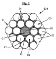
図2は、本発明の上述の方法を用いて得ることができる好ましい現場ゴム引き1+6+12コードの一例をコード(真っ直ぐであると共に休止状態にあると仮定されている)の軸線に垂直な断面で概略的に示している。 FIG. 2 schematically illustrates an example of a preferred in-situ rubberized 1 + 6 + 12 cord that can be obtained using the above-described method of the present invention in a cross section perpendicular to the axis of the cord (assumed to be straight and at rest). Is shown.
このコード(C‐1で示されている)は、コンパクト型のものであり、即ち、その第2の層及び第3の層(それぞれC2及びC3)が同一方向に(公認の命名法を用いるとS/S又はZ/Z)に巻かれると共にこれに加えて同一ピッチ(p2=p3)を有している。この種の構造は、これら第2の層及び第3の層(C2,C3)のワイヤ(21,22)が、コア(20)又は第1の層(C1)の周りに、各々がいわゆる円筒形層タイプのコードの場合のように円筒形ではなく、実質的に多角形(具体的に言えば六角形)である輪郭(E)を有する2つの実質的に同心の層を形成するという結果をもたらす。 This code (indicated by C-1) is of the compact type, ie its second and third layers (C2 and C3 respectively) are in the same direction (using recognized nomenclature) And S / S or Z / Z), and in addition to this, have the same pitch (p 2 = p 3 ). In this type of structure, the wires (21, 22) of the second layer and the third layer (C2, C3) are arranged around the core (20) or the first layer (C1), each of which is a so-called cylinder. The result of forming two substantially concentric layers having a contour (E) that is substantially polygonal (specifically hexagonal) rather than cylindrical as in the case of a layered type cord Bring.
本発明のこのコードは、現場ゴム引きコードと呼ばれる場合があり、一方においてコア(C1)と第2の層(C2)のN本のワイヤとの間に位置すると共に他方において第2の層(C2)のN本のワイヤと第3の層(C3)のP本のワイヤとの間に位置した毛管又は隙間(隣り合うワイヤにより形成されていて、充填ゴムが存在しない場合には空の空間)の各々は、少なくとも部分的に、連続して又はコードの軸線に沿って、充填ゴムで満たされており、その結果、コードの任意の2cm長さ分に関して、毛管の各々は、ゴムで作られた少なくとも1つの栓を有する。 This cord of the present invention may be referred to as an in-situ rubberized cord, located on the one hand between the core (C1) and the N wires of the second layer (C2) and on the other hand the second layer ( Capillaries or gaps located between the N wires of C2) and the P wires of the third layer (C3) (empty space if formed by adjacent wires and no filled rubber is present) ) At least partially, continuously or along the axis of the cord, is filled with filled rubber, so that for any 2 cm length of cord, each capillary is made of rubber. At least one stopper.
具体的に説明すると、充填ゴム(23)は、非常に僅かに離れたコードの種々の層(C1,C2,C3)の隣り合うワイヤ(3本ずつの状態であると考えられる)によって形成された各毛管(24)(三角形によって表されている)を充填している。理解できるように、これら毛管又は隙間は、当然のことながら、コアワイヤ(20)及びこの周りの第2の層(C2)のワイヤ(21)か、第2の層(C2)の2本のワイヤ(21)及びこれらのすぐ隣りに位置する第3の層(C3)の1本のワイヤ(23)かのいずれかによって形成され、変形例として、更に、第2の層(C2)の各ワイヤ(21)及びこのすぐ隣りに位置する第3の層(C3)の2本のワイヤ(22)によって形成され、かくして、全体として、この1+6+12コードには24個の毛管又は隙間(24)が存在する。 Specifically, the filled rubber (23) is formed by adjacent wires (possibly in three pieces) of various layers (C1, C2, C3) of the cord that are very slightly separated. Each capillary (24) (represented by a triangle) is filled. As can be seen, these capillaries or gaps are, of course, the core wire (20) and the second layer (C2) wire (21) around it or the two wires of the second layer (C2). (21) and one of the wires (23) of the third layer (C3) located immediately adjacent thereto, and as a modification, each wire of the second layer (C2) (21) and the two wires (22) of the third layer (C3) located immediately adjacent thereto, and thus there are 24 capillaries or gaps (24) in the 1 + 6 + 12 cord as a whole. To do.
好ましい実施形態によれば、この好ましい1+N+Pコードでは、充填ゴムは、好ましくは、これが覆っている第2の層(C2)の周りに連続して延びる。 According to a preferred embodiment, in this preferred 1 + N + P cord, the filled rubber preferably extends continuously around the second layer (C2) that it covers.
比較すると、図3は、これ又コンパクト型の従来型1+6+12コード(C‐2で示されている)、即ち、コンパクト型の場合と同様、現場でゴム引きされていないコードの残部を断面で示している。充填ゴムが設けられていないことは、事実上全てのワイヤ(30,31,32)が互いに接触状態にあり、その結果、特にコンパクトであるが、他方において、ゴムが外部から侵入するのを更に極めて困難にする(不浸透性であるというわけではない)構造体が生じる。この種のコードの特徴は、3本ずつの形態の種々のワイヤがチャネル又は毛管(34)を形成し、これらチャネル又は毛管は、これらが多数である場合、閉鎖されると共に空のままであり、従って「ウィッキング」効果により腐食性媒体、例えば水の伝搬に都合が良い。 In comparison, FIG. 3 shows a cross-section of the remaining part of the compact conventional 1 + 6 + 12 cord (indicated by C-2), ie, the cord that is not rubberized in the field, as in the compact type. ing. The absence of a filling rubber means that virtually all the wires (30, 31, 32) are in contact with each other and, as a result, are particularly compact, but on the other hand, the further penetration of the rubber from the outside A structure is created that makes it very difficult (not impermeable). A feature of this type of cord is that various wires in triplicate form channels or capillaries (34) that are closed and empty when they are numerous. Therefore, the “wicking” effect favors the propagation of corrosive media such as water.
好ましい例を挙げると、本発明の方法は、1+6+11及び1+6+12構造のコードの製造に用いられ、特に、後者のコードは、第2の層(C2)から第3の層(C3)まで実質的に同一の直径(即ち、この場合、d2=d3)を有するワイヤから成る。 As a preferred example, the method of the present invention is used for the manufacture of 1 + 6 + 11 and 1 + 6 + 12 structured cords, in particular the latter cord is substantially from the second layer (C2) to the third layer (C3). It consists of wires having the same diameter (ie in this case d 2 = d 3 ).
II.本発明の実施形態 II. Embodiment of the present invention
以下の試験は、先行技術の現場ゴム引き3層コードと比較して、少量の充填ゴムを含み、良好なコンパクトさを保証する顕著な利点を有する3層コードを提供する本発明の方法の性能を実証しており、このゴムは又、その毛管の各々の中でコードの内部に一様に分布され、かくして、コードに最適な不浸透性が与えられる。 The following tests show the performance of the method of the present invention to provide a three-layer cord that has a significant advantage of ensuring good compactness, including a small amount of filled rubber, as compared to prior art field rubberized three-layer cords. This rubber is also distributed uniformly within the cord within each of its capillaries, thus giving the cord an optimum impermeability.
II‐1.用いられる測定及び試験II-1. Measurements and tests used
II‐1‐A.引張特性(ダイナモメトリック)測定II-1-A. Tensile property (dynamometric) measurement
金属ワイヤ及び金属コードに関し、破断荷重Fm(単位N(ニュートン)の最大荷重)、Rmにより示された引張強度(単位MPa)及びAtにより示された破断点伸び率(単位%の全伸び率)の測定は、1984年の規格ISO6892に従って張力下で行われる。 For metal wires and metal cords, breaking load Fm (maximum load in unit N (Newton)), tensile strength indicated by Rm (unit MPa), and elongation at break indicated by At (total elongation in unit%) Is measured under tension in accordance with the 1984 standard ISO 6892.
ゴムコンパウンド(配合物)に関し、弾性率(モジュラス)の測定は、別段の指定がなければ、1998年の標準ASTM・D・412(試験体“C”)に従って引張下で実施され、即ち、E10と呼ばれていてMPaで表された10%伸び率における「真」の割線モジュラス(試験体の実断面に関する割線モジュラス)を1999年の規格ASTM・D・1349による通常の温度及び湿度条件下で第2の伸びで(即ち、1回の適合サイクル後に)測定する。 For rubber compounds (compounds), the measurement of modulus of elasticity (modulus) is carried out under tension according to the standard ASTM D 412 (test specimen “C”), unless otherwise specified, ie E10. The "true" secant modulus (secant modulus for the actual cross section of the specimen) at 10% elongation expressed in MPa under normal temperature and humidity conditions according to the 1999 standard ASTM D 1349 Measure at the second elongation (ie, after one fit cycle).
II‐1‐B.通気度試験II-1-B. Air permeability test
この試験により、試験対象のコードの長手方向通気度を所与の時間にわたり一定の圧力下で試験体を通過した空気の量を測定することによって決定することができる。当業者には周知であるかかる試験の原理は、コードが空気に対して不透過性であるようにするためにコードの処理の有効性を実証することにある。この試験は、例えば、規格ASTM・D・2692‐98に記載されている。 With this test, the longitudinal air permeability of the cord under test can be determined by measuring the amount of air that has passed through the specimen under a certain pressure over a given time. The principle of such testing, well known to those skilled in the art, is to demonstrate the effectiveness of the processing of the cord to ensure that the cord is impermeable to air. This test is described, for example, in the standard ASTM D 2692-98.
この試験は、ここでは、タイヤ又はタイヤを補強しているゴムプライから抽出したコード(従って、既に外側が硬化ゴムですでに被覆されたコード)か製造されたばかりのコードかのいずれかに対して行われる。 This test is here performed either on a cord extracted from a tire or a rubber ply reinforcing the tire (thus a cord already covered with a hardened rubber on the outside) or a cord just manufactured. Is called.
後者の場合、製造されたばかりのコードは、まず最初に外部から被覆ゴムと呼ばれているゴムで被覆されなければならない。これを行うため、互いに平行であるように配列された一連の10本のコード(20mmのコード間距離)を硬化ゴムコンパウンドの2つのスキム(80×200mmの2つの長方形)相互間に配置し、各スキムの厚さは、3.5mmであり、次に、組立体全体をモールド内にクランプし、コードの各々は、クランプモジュールを用いてモールド内に配置されたときにこれが真っ直ぐのままであるようにするために十分な張力(例えば、2daN)下に維持され、加硫(硬化)プロセスは、140℃の温度で且つ15バールの圧力(80×200mmの長方形ピストンによって加えられる)下で40分にわたって行われる。その後、組立体を脱型し、ば特徴付けのために7×7×20mmの平行六面体の形態をした上述のように被覆されているコードの10個の試験体の状態に切断する。 In the latter case, the cords that have just been produced must first be coated with a rubber called the coated rubber from the outside. To do this, a series of ten cords (20 mm cord distance) arranged to be parallel to each other are placed between two skims (two 80 x 200 mm rectangles) of the cured rubber compound, The thickness of each skim is 3.5 mm, then the entire assembly is clamped in the mold, and each of the cords remains straight when placed in the mold using a clamp module Maintained under sufficient tension (e.g. 2 daN) so that the vulcanization (curing) process is carried out at a temperature of 140 ° C. and under a pressure of 15 bar (applied by an 80 × 200 mm rectangular piston). Done over a minute. The assembly is then demolded and cut into 10 specimens of cords coated as described above in the form of 7 × 7 × 20 mm parallelepipeds for characterization.
従来型タイヤゴムコンパウンドを被覆ゴムとして用い、かかるゴムコンパウンドは、天然(解凝固)ゴム及びN330カーボンブラック(60phr)を主成分とし、更に以下の通常の添加剤、即ち、硫黄(7phr)、スルフェンアミド促進剤(1phr)、ZnO(8phr)、ステアリン酸(0.7phr)、酸化防止剤(1.5phr)及びコバルトナフテネート(1.5phr)を更に含み(なお、phrは、ゴムの100部当たりの重量部を意味している)、被覆ゴムの弾性率E10は、約10MPaである。 A conventional tire rubber compound is used as a covering rubber. The rubber compound is composed mainly of natural (decoagulated) rubber and N330 carbon black (60 phr), and further contains the following usual additives, namely, sulfur (7 phr), sulfene. Further included amide accelerator (1 phr), ZnO (8 phr), stearic acid (0.7 phr), antioxidant (1.5 phr) and cobalt naphthenate (1.5 phr) (where phr is 100 parts of rubber) The elastic modulus E10 of the coated rubber is about 10 MPa.
例えば、試験を以下の仕方で、ここでは包囲ゴムコンパウンド(又は被覆ゴム)で被覆されたコードの2cm長さ分について実施し、1バールの圧力下で空気をコードの入口に注入し、流量計を用いてこれから出る空気の量を測定する(例えば、0〜500cm3/分まで較正する)。測定中、コード試験体をコードの長手方向軸線に沿って一端から他端までコードを通過した空気の量だけが測定されるよう圧縮気密シール(例えば、高密度フォーム又はゴムシール)中に不動化し、シールの密封能力を前もって、中実ゴム試験体を用いて、即ち、コードなしのゴム試験体を用いてチェックする。 For example, the test is carried out in the following manner, here for a 2 cm length of cord covered with a surrounding rubber compound (or coated rubber), air is injected into the cord inlet under a pressure of 1 bar, and a flow meter Use to measure the amount of air coming out of it (e.g. calibrate to 0-500 cm < 3 > / min). During measurement, the cord specimen is immobilized in a compression-tight seal (eg, high density foam or rubber seal) so that only the amount of air that has passed through the cord from one end to the other along the longitudinal axis of the cord is measured, The sealing capacity of the seal is checked in advance using a solid rubber specimen, i.e. using a rubber specimen without a cord.
コードの長手方向不透過性が高ければ高いほど、測定された平均空気流量(10個の試験体の平均値)がそれだけ一層低い。測定値は±0.2cm3/分という精度を持っているので、0.2cm3/分以下の測定値は、ゼロと見なされ、これら測定値は、コード軸線に沿って(即ち、コード長手方向に沿って)気密(完全に気密)であるといえるコードに対応している。 The higher the longitudinal impermeability of the cord, the lower the measured average air flow (average of 10 specimens). Since the measurement value has an accuracy of ± 0.2 cm 3 / min, 0.2 cm 3 / min following measurements are considered zero, these measurements along the cord axis (i.e., the code length Corresponds to code that is airtight (along the direction).
II‐1‐C.充填ゴム含有量II-1-C. Filled rubber content
充填ゴムの量は、初期コード(従って、現場ゴム引きコード)の重量と適当な電解処理によって充填ゴムを除去したコード(従って、そのワイヤのコード)の重量の差を測定することによって測定される。 The amount of filled rubber is measured by measuring the difference between the weight of the initial cord (and therefore the in-situ rubberized cord) and the weight of the cord (and hence the wire cord) from which the filled rubber has been removed by appropriate electrolytic treatment. .
サイズを減少するためにそれ自体巻かれたコード試験片(長さ1m)は、電解槽のカソード(発電機の負端子に接続されている)を構成し、アノード(正端子に接続されている)は、白金ワイヤから成っている。 A cord specimen (length 1 m), itself wound to reduce size, constitutes the cathode of the electrolytic cell (connected to the negative terminal of the generator) and the anode (connected to the positive terminal) ) Is made of platinum wire.
電解質は、1リットル当たり1モルの炭酸ナトリウムを含む水溶液(脱イオン水)から成っている。 The electrolyte consists of an aqueous solution (deionized water) containing 1 mole of sodium carbonate per liter.
電解質中に完全に浸漬された試験片には、15分間電圧が印加され、流れた電流は300mAである。次に、コードを浴から取り出し、十分に水ですすぎ洗いする。この処理により、ゴムをコードから容易に取り去ることができる(そうでない場合でも、電解は数分間続く)。例えば、ワイヤをコードから1本ずつほどきながら吸収布を用いてゴムを単に拭うことによりゴムを注意深く除去する。再び、ワイヤを水ですすぎ洗いし、次に脱イオン水(50%)とエタノール(50%)の混合液の入っているビーカ内に浸漬させる。ビーカを10分間超音波浴内に浸漬する。このようにして全ての微量ゴムを取り除いたワイヤをビーカから取り出し、窒素又は空気の流れ中で乾燥させ、最後に秤量する。 A voltage is applied to the test piece completely immersed in the electrolyte for 15 minutes, and the flowing current is 300 mA. The cord is then removed from the bath and rinsed thoroughly with water. This treatment allows the rubber to be easily removed from the cord (even if not, electrolysis continues for several minutes). For example, the rubber is carefully removed by simply wiping the rubber with an absorbent cloth while unwinding the wires one by one from the cord. Again, the wire is rinsed with water and then immersed in a beaker containing a mixture of deionized water (50%) and ethanol (50%). Immerse the beaker in an ultrasonic bath for 10 minutes. The wire, from which all traces of rubber have been removed, is removed from the beaker, dried in a stream of nitrogen or air, and finally weighed.
このことから、計算により、10回の測定(即ち、全部でコード10m分について)の平均された初期コードの1g(グラム)当たりの充填ゴムのmg(ミリグラム)で表わされたコード中の充填ゴム含有量が導き出される。 From this, the filling in the cord expressed in mg (milligrams) of filled rubber per g (gram) of the initial cord averaged over 10 measurements (ie for a total of 10 m of cord) is calculated. Rubber content is derived.
II‐2.コードの製造及び試験II-2. Code manufacturing and testing
以下の試験において、真鍮で被覆された炭素鋼ワイヤで作られた1+6+12構造の層状コードを製造した。 In the following test, a layered cord of 1 + 6 + 12 structure made of carbon steel wire coated with brass was produced.
炭素鋼ワイヤを公知の仕方で、例えば、機械ワイヤ(直径5〜6mm)を先ず最初に圧延及び/又は引き抜きによりほぼ1mmの中間直径まで加工硬化させることによって調製した。用いたスチールは、炭素含有量が0.70%の公知の炭素鋼(米国規格AISI 1069)であった。中間直径のワイヤは、脱脂及び/又は酸洗い処理を受け、その後、これらを変換する。真鍮の被膜をこれら中間ワイヤに被着させた後、「最終」加工硬化と呼ばれる作業を、例えば水性乳濁液又は分散液の形態をした絞り成形用潤滑剤を含む湿式媒体中で冷間絞り成形することにより各ワイヤに対して行った(即ち、最終パテンティング熱処理後)。ワイヤを包囲している真鍮の被膜は、非常に小さい厚さのものであり、1ミクロンよりも著しく小さく、例えば、約0.15〜0.30μmであり、これは、スチールワイヤの直径と比べて無視できるほどのものであった。このようにして引き抜いたスチールワイヤは、以下の表1に示された直径及び機械的性質を有していた。 Carbon steel wire was prepared in a known manner, for example, by first mechanically hardening a machine wire (5-6 mm diameter) to an intermediate diameter of approximately 1 mm by rolling and / or drawing. The steel used was a known carbon steel (US standard AISI 1069) with a carbon content of 0.70%. Intermediate diameter wires are subjected to a degreasing and / or pickling treatment, after which they are converted. After the brass coating has been applied to these intermediate wires, an operation called “final” work hardening is performed by cold drawing in a wet medium containing, for example, a drawing lubricant in the form of an aqueous emulsion or dispersion. Each wire was formed by molding (ie, after the final patenting heat treatment). The brass coating surrounding the wire is of a very small thickness and is significantly smaller than 1 micron, for example about 0.15 to 0.30 μm, compared to the diameter of the steel wire. Was negligible. The steel wire drawn in this way had the diameters and mechanical properties shown in Table 1 below.

次に、これらワイヤを1+6+12構造の層状コードの形態に組み立て、これらの構成は、図1に示されており、その機械的性質は、表2に記載されている。 These wires are then assembled in the form of a layered cord with a 1 + 6 + 12 structure, the configuration of which is shown in FIG. 1 and its mechanical properties are listed in Table 2.
図1に概略的に示されているような本発明の方法に従って調製された1+6+12コードの実施例(C‐1)を直径が0.20mmの全部で19本のワイヤ及びその周りの全て直径が0.18mmの18本のワイヤで構成し、これらワイヤを同一ピッチ(p1=p2=10.0mm)で且つ同一撚り方向(S)で巻いてコンパクト型のコードを得た。段落II‐1‐Cにおいて上述した方法を用いて測定した充填ゴムの含有量は、コード1g当たり約16mgであった。この充填ゴムは、3本ずつと考えられる種々のワイヤによって形成された24個の毛管の各々の中に存在し、即ち、充填ゴムは、これら毛管の各々を完全に又は少なくとも部分的に充填し、コードの任意の2cm長さ分に関し、各毛管内にゴムの少なくとも1つの栓が存在するようにした。 A 1 + 6 + 12 cord embodiment (C-1) prepared according to the method of the present invention as schematically shown in FIG. 1 has a total diameter of 0.20 mm and a total of 19 wires and all surrounding diameters. It was composed of 18 wires of 0.18 mm, and these wires were wound at the same pitch (p 1 = p 2 = 10.0 mm) and in the same twist direction (S) to obtain a compact cord. The content of filled rubber, measured using the method described above in paragraph II-1-C, was about 16 mg / g cord. This filled rubber is present in each of the 24 capillaries formed by various wires considered to be 3 each, i.e., the filled rubber completely or at least partially fills each of these capillaries. There was at least one plug of rubber in each capillary for any 2 cm length of cord.
このコードを製造するため、上述すると共に図1に概略的に示された装置を用いた。充填ゴムは、産業車両用のタイヤのカーカス補強材用の従来型ゴムコンパウンドであり、かかるゴムコンパウンドは、コードC‐1が補強するようになったゴムカーカスプライと同じ配合を有し、このコンパウンドは、天然(解凝固)ゴム及びN330カーボンブラック(55phr)を主成分としており、このコンパウンドは、次の通常の添加物、即ち、硫黄(7phr)、スルフェンアミド促進剤(1phr)、ZnO(9phr)、ステアリン酸(0.7phr)、酸化防止剤(1.5phr)及びコバルトナフテネート(1phr)を更に含んでおり、コンパウンドの弾性率E10は、約6MPaであった。このコンパウンドを、それぞれ0.250mm及び0.580mmの2つのサイジングダイ(11a,11b)により約85℃の温度で押し出した。 In order to produce this cord, the apparatus described above and schematically shown in FIG. 1 was used. Filling rubber is a conventional rubber compound for carcass reinforcement of tires for industrial vehicles, and this rubber compound has the same composition as the rubber carcass ply that is reinforced by the cord C-1. Is based on natural (decoagulated) rubber and N330 carbon black (55 phr), and this compound contains the following conventional additives: sulfur (7 phr), sulfenamide accelerator (1 phr), ZnO ( 9 phr), stearic acid (0.7 phr), antioxidant (1.5 phr) and cobalt naphthenate (1 phr), and the elastic modulus E10 of the compound was about 6 MPa. This compound was extruded at a temperature of about 85 ° C. by two sizing dies (11a, 11b) of 0.250 mm and 0.580 mm, respectively.
このようにして調製されたコードC‐1に1分でコードを通る空気の体積(単位:cm3)を測定することにより段落II‐1‐Bにおいて説明した通気度試験を実施した(試験された各コードについて10回の測定値の平均値を取った)。試験した各コードC‐1に関し且つ測定値の100%に関し(即ち、10個のうちで10個の試験片)、流量の測定値は、ゼロ又は0.2cm3/分未満であり、換言すると、本発明のコードは、これらの軸線に沿って気密であると見なされ、従って、これらは、ゴムによる最適の侵入レベルを有している。
The air permeability test described in paragraph II-1-B was carried out by measuring the volume (unit: cm 3 ) of air passing through the cord in 1 minute on the cord C-1 thus prepared (tested). For each cord, the average value of 10 measurements was taken). For each code C-1 tested and for 100% of the measured value (
さらに、現場ゴム引きされると共に本発明のコンパクトコードC‐1と同一構造のコントロールコードを上述の国際公開第2005/071557号パンフレットに記載されている方法に従って数個の不連続ステップで調製し、即ち、押出ヘッドを用いて中間1+6コアストランドを外装し、次に第2段階において、残りの12本のワイヤをこのようにして外装されたコアの周りにケーブリングして外側層を形成した。次に、これらコントロールコードに段落II‐1‐Bの通気度試験を行った。 Furthermore, a control cord which is rubberized in the field and has the same structure as the compact cord C-1 of the present invention is prepared in several discontinuous steps according to the method described in the above-mentioned WO 2005/071557, That is, an intermediate 1 + 6 core strand was sheathed using an extrusion head, and then in the second stage, the remaining 12 wires were cabled around the core thus sheathed to form an outer layer. Next, the air permeability test of Paragraph II-1-B was performed on these control codes.
まず最初に、これらコントロールコードの中で、ゼロ又は0.2cm3/分未満の100%(即ち、10個のうちで10個の試験片)の流量測定値をもたらしたものはなく、換言すると、これらコントロールコードの中で、その軸線に沿って気密(完全に気密)であると見なされたものはなかった。また、これらコントロールコードの中で、最善の通気度結果(即ち、約2cm3/分の平均流量)を示したコントロールコードは全て、これらの周囲からの比較的多量の望ましくない充填ゴムのオーバースピルを示し、これらコードが工業条件下における満足のゆく圧延作業には不適当であったことが判明した。
First of all, none of these control codes resulted in a flow measurement of 100% (
以上を要約すると、本発明の方法は、本発明の方法により、現場ゴム引きされたM+N+Pコードであって、ゴムの最適侵入レベルにより、一方において、タイヤカーカス補強材に高い耐久性を示すと共に他方において特にコードの製造中、ゴムの過剰のオーバースピルと関連した問題なしに工業条件下において効率的に使用できるコードの製造が可能である。 In summary, the method of the present invention is an M + N + P cord that has been rubberized in-situ according to the method of the present invention, and on the one hand exhibits high durability to the tire carcass reinforcement and, on the other hand, due to the optimum penetration level of rubber. In particular, during cord production, it is possible to produce cords that can be used efficiently under industrial conditions without the problems associated with excessive overspilling of rubber.
Claims (11)
‐前記コア(C1)を前記充填ゴムで外装する第1の外装ステップ、
‐このように外装された前記第1の層(C1)周りに前記第2の層(C2)の前記N本のワイヤをツイスティングしてコアストランドと呼ばれる中間コード(C1+C2)を組み立て箇所と呼ばれる箇所で形成する第1の組み立てステップ、
‐前記組み立て箇所の下流側で、前記コアストランド(C1+C2)を前記充填ゴムで外装する第2の外装ステップ、
‐前記第3の層(C3)の前記P本のワイヤを外装された前記コアストランドの周りにツイスティングする第2の組み立てステップ、及び
‐最終の撚りバランス取りステップを有する、方法。 A method for producing a metal cord comprising three concentric layers (C1, C2, C3) comprising a compound made of in-situ rubberized type, i.e. a compound made of uncrosslinked rubber called filled rubber, The cord is helical with a pitch p 2 of N wires of diameter d 2 (where N varies from 3 to 12) as a second intermediate layer (C2) on the first inner layer or core (C1) Are wound together, and the second intermediate layer is wound together with P wires of diameter d 3 (where P varies from 8 to 20) as a third outer layer (C 3) at a pitch p 3. The method comprises the following steps:
-A first exterior step of sheathing the core (C1) with the filled rubber;
- are thus referred to as point assembled intermediate code (C1 + C2), called the N number of the core strand by twisting the wire armored the first layer (C1) the second layer around (C2) A first assembly step to form at a location;
-A second exterior step of sheathing the core strand (C1 + C2) with the filled rubber downstream of the assembly location;
A second assembly step in which the P wires of the third layer (C3) are twisted around the sheathed core strand, and a final twist balancing step.
‐前記第1の層又はコア(C1)を供給する供給手段と、
‐前記コア(C1)を外装する第1の外装手段と、
‐前記第2の層(C2)の前記N本のワイヤを供給する供給手段及び前記N本を組み立て箇所と呼ばれる箇所で前記外装されたコア(C1)の周りにツイスティングした状態で組み立てて「コアストランド」と呼ばれる中間コード(C1+C2)を形成する第1の組み立て手段と、
‐前記組み立て箇所の下流側に設けられていて、前記コアストランド(C1+C2)を外装する第2の外装手段と、
‐前記第2の外装手段の出口のところに設けられていて、前記第3の層(C3)を供給する供給手段及び前記P本のワイヤを前記コアストランド(C1+C2)の周りにツイスティングした状態で組み立てて前記第3の層(C3)を被着させる第2の組み立て手段と、
‐前記第2の組み立て手段の出口のところに設けられた撚りバランス取り手段とを有する、装置。 It is an inline type rubberizing and assembling device , from the upstream side to the downstream side as seen in the moving direction of the cord being formed,
-Supply means for supplying said first layer or core (C1);
-A first exterior means for exteriorizing the core (C1);
-The supply means for supplying the N wires of the second layer (C2) and the N wires are assembled in a state twisted around the sheathed core (C1) at a place called an assembly place. First assembling means for forming an intermediate cord (C1 + C2) called “core strand”;
-A second exterior means provided on the downstream side of the assembly location, for exteriorizing the core strand (C1 + C2);
-A state of being provided at the outlet of the second exterior means, the supply means for supplying the third layer (C3) and the P wires twisted around the core strand (C1 + C2) Second assembly means for assembling and depositing the third layer (C3);
A twist balancing means provided at the outlet of the second assembly means;
Applications Claiming Priority (3)
| Application Number | Priority Date | Filing Date | Title |
|---|---|---|---|
| FR0952020A FR2943691B1 (en) | 2009-03-31 | 2009-03-31 | METHOD AND DEVICE FOR MANUFACTURING A THREE-LAYER CABLE OF THE TYPE IN SITU GUM |
| FR0952020 | 2009-03-31 | ||
| PCT/EP2010/054063 WO2010112445A1 (en) | 2009-03-31 | 2010-03-29 | Method and device for producing a three-layer cord |
Publications (3)
| Publication Number | Publication Date |
|---|---|
| JP2012522144A JP2012522144A (en) | 2012-09-20 |
| JP2012522144A5 JP2012522144A5 (en) | 2013-04-11 |
| JP5591909B2 true JP5591909B2 (en) | 2014-09-17 |
Family
ID=40941496
Family Applications (1)
| Application Number | Title | Priority Date | Filing Date |
|---|---|---|---|
| JP2012502612A Expired - Fee Related JP5591909B2 (en) | 2009-03-31 | 2010-03-29 | Method and apparatus for producing on-site rubberized three-layer cord |
Country Status (6)
| Country | Link |
|---|---|
| US (1) | US8720176B2 (en) |
| EP (1) | EP2414583B1 (en) |
| JP (1) | JP5591909B2 (en) |
| CN (1) | CN102365404B (en) |
| FR (1) | FR2943691B1 (en) |
| WO (1) | WO2010112445A1 (en) |
Families Citing this family (19)
| Publication number | Priority date | Publication date | Assignee | Title |
|---|---|---|---|---|
| FR2938558B1 (en) * | 2008-11-17 | 2010-12-31 | Michelin Soc Tech | METHOD AND DEVICE FOR MANUFACTURING A THREE LAYER CABLE OF THE TYPE IN SITU GUM. |
| FR2943690B1 (en) * | 2009-03-31 | 2011-08-19 | Michelin Soc Tech | METHOD AND DEVICE FOR MANUFACTURING A THREE LAYER CABLE OF THE TYPE GUM A SITU |
| FR2946366B1 (en) * | 2009-06-03 | 2011-12-02 | Michelin Soc Tech | THREE-LAYER CABLE, IN SITU GUM, FOR PNEUMATIC CARCASS REINFORCEMENT. |
| FR2947576B1 (en) * | 2009-07-03 | 2011-08-19 | Michelin Soc Tech | METAL CABLE WITH THREE LAYERS GUM IN SITU CONSTRUCTION 2 + M + N |
| FR2947577B1 (en) * | 2009-07-03 | 2013-02-22 | Michelin Soc Tech | METAL CABLE WITH THREE LAYERS GUM IN SITU CONSTRUCTION 3 + M + N |
| FR2962454B1 (en) * | 2010-05-20 | 2012-09-21 | Michelin Soc Tech | PROCESS FOR MANUFACTURING A THREE-LAYER METAL CABLE OF THE TYPE IN SITU GUM |
| FR2962456B1 (en) * | 2010-05-20 | 2012-09-21 | Michelin Soc Tech | PROCESS FOR MANUFACTURING A MULTILAYER METALLIC CABLE IN SITU GUM BY AN UNSATURATED THERMOPLASTIC ELASTOMER |
| FR2969038B1 (en) * | 2010-12-21 | 2012-12-28 | Michelin Soc Tech | TIRE WITH CARCASE FRAME REINFORCED BY A LAYER OF REINFORCING ELEMENTS IN THE BOURRELET AREA |
| FR2969036B1 (en) * | 2010-12-21 | 2012-12-28 | Michelin Soc Tech | TIRE WITH CARCASE FRAME REINFORCED BY A LAYER OF REINFORCING ELEMENTS IN THE BOURRELET AREA |
| FR2969035B1 (en) * | 2010-12-21 | 2014-08-29 | Michelin Soc Tech | TIRE WITH CARCASE FRAME REINFORCED BY A LAYER OF REINFORCING ELEMENTS IN THE BOURRELET AREA |
| FR2969037B1 (en) * | 2010-12-21 | 2014-08-29 | Michelin Soc Tech | TIRE WITH CARCASE FRAME REINFORCED BY A LAYER OF REINFORCING ELEMENTS IN THE BOURRELET AREA |
| FR2997410B1 (en) * | 2012-10-30 | 2016-01-01 | Michelin & Cie | IN SITU GUM CABLE COMPRISING A COMPOSITION COMPRISING A STYRENE BUTADIENE COPOLYMER |
| FR3022264A1 (en) | 2014-06-12 | 2015-12-18 | Michelin & Cie | SEMI-FINISHED PRODUCT COMPRISING A CABLE IN SITU GUM NOYE IN A CALENDER RUBBER COMPOSITION |
| FR3022262B1 (en) | 2014-06-12 | 2016-06-03 | Michelin & Cie | IN SITU GUM CABLE COMPRISING A SCRUB COMPOSITION COMPRISING A CORROSION INHIBITOR |
| FR3022261B1 (en) | 2014-06-12 | 2016-06-03 | Michelin & Cie | IN SITU GUM CABLE COMPRISING A SCRUB COMPOSITION COMPRISING A CORROSION INHIBITOR |
| FR3022822B1 (en) | 2014-06-30 | 2016-10-28 | Michelin & Cie | METHOD AND DEVICE FOR MANUFACTURING RUBBER-COATED METAL WIRE |
| JP5811240B1 (en) * | 2014-06-30 | 2015-11-11 | 横浜ゴム株式会社 | Steel cord and conveyor belt |
| US20170175803A1 (en) * | 2015-12-21 | 2017-06-22 | Kongsberg Power Products Systems I, Inc. | Cable Of A Remote Control Assembly |
| JP2020525666A (en) * | 2017-06-27 | 2020-08-27 | ベカルト アドバンスド コーズ アールテル エンベーBekaert Advanced Cords Aalter Nv | Reinforcing strands for reinforcing polymer articles |
Family Cites Families (24)
| Publication number | Priority date | Publication date | Assignee | Title |
|---|---|---|---|---|
| FR812539A (en) * | 1936-10-26 | 1937-05-12 | Michelin & Cie | Improvement to tire beads |
| JPH06200491A (en) * | 1992-12-28 | 1994-07-19 | Bridgestone Metarufua Kk | Method for correcting steel cord and apparatus therefor |
| DE69414912T2 (en) * | 1993-06-02 | 1999-04-22 | Bekaert Sa Nv | Compact steel cable without a sheathing element |
| EP0635597A1 (en) * | 1993-07-20 | 1995-01-25 | N.V. Bekaert S.A. | Steel cord construction |
| US5806296A (en) * | 1995-05-26 | 1998-09-15 | Bridgestone Metalpha Corporation | Corrosion resistant spiral steel filament and steel cord made therefrom |
| EP1038064B1 (en) * | 1997-12-15 | 2003-03-26 | N.V. Bekaert S.A. | Steel cord with polymer material |
| TW522180B (en) * | 2000-05-18 | 2003-03-01 | Asahi Chemical Ind | Dyed yarn |
| US20020053386A1 (en) * | 2000-09-11 | 2002-05-09 | The Yokohama Rubber Co., Ltd. | Steel cord for tire and radial tire |
| US7152391B2 (en) * | 2000-12-01 | 2006-12-26 | Nv Bekaert Sa | Steel cord for reinforcing off-the-road tires and conveyor belts |
| JP2002266266A (en) * | 2001-03-13 | 2002-09-18 | Yokohama Rubber Co Ltd:The | Method for producing elastomer composite steel cord |
| DE10213289A1 (en) * | 2001-03-30 | 2002-11-14 | Yokohama Rubber Co Ltd | Elastomer and steel cord composite and process for making the same |
| JP4049627B2 (en) * | 2002-07-02 | 2008-02-20 | トクセン工業株式会社 | Elastomer composite steel cord and manufacturing method thereof |
| JP4316904B2 (en) * | 2003-03-14 | 2009-08-19 | 不二精工株式会社 | Rubber coated steel cord manufacturing apparatus, cord, rubber ribbon using the cord, and tire manufacturing method using the same |
| CN100572655C (en) * | 2003-07-17 | 2009-12-23 | 贝卡尔特股份有限公司 | Open layered steel cord with high breaking load |
| FR2864556B1 (en) * | 2003-12-24 | 2006-02-24 | Michelin Soc Tech | LAYERED CABLE FOR PNEUMATIC CARCASS REINFORCEMENT |
| US20050182884A1 (en) | 2004-01-22 | 2005-08-18 | Hofmann Richard G. | Multiple address two channel bus structure |
| FR2869618B1 (en) | 2004-04-30 | 2008-10-10 | Michelin Soc Tech | IMPROVED ADHESIVE RUBBER COMPOSITION WITH A METAL REINFORCEMENT. |
| JP4940753B2 (en) * | 2006-05-15 | 2012-05-30 | 横浜ゴム株式会社 | Steel cord for rubber reinforcement and method for producing pneumatic radial tire using the same |
| JP2008297667A (en) * | 2007-05-31 | 2008-12-11 | Yokohama Rubber Co Ltd:The | Steel cord, method for producing same and pneumatic tire |
| JP2009084711A (en) * | 2007-09-27 | 2009-04-23 | Bridgestone Corp | Process for producing rubber-steel composite cord and thus obtained rubber-steel composite cord |
| FR2925923B1 (en) * | 2007-12-28 | 2009-12-18 | Michelin Soc Tech | METHOD AND DEVICE FOR MANUFACTURING A TWO-LAYER CABLE OF THE TYPE IN SITU GUM |
| FR2925922B1 (en) * | 2007-12-28 | 2009-12-18 | Soc Tech Michelin | LAYERED CABLE FOR PNEUMATIC BELT |
| FR2938558B1 (en) * | 2008-11-17 | 2010-12-31 | Michelin Soc Tech | METHOD AND DEVICE FOR MANUFACTURING A THREE LAYER CABLE OF THE TYPE IN SITU GUM. |
| FR2943690B1 (en) * | 2009-03-31 | 2011-08-19 | Michelin Soc Tech | METHOD AND DEVICE FOR MANUFACTURING A THREE LAYER CABLE OF THE TYPE GUM A SITU |
-
2009
- 2009-03-31 FR FR0952020A patent/FR2943691B1/en not_active Expired - Fee Related
-
2010
- 2010-03-29 CN CN201080014110.3A patent/CN102365404B/en not_active Expired - Fee Related
- 2010-03-29 JP JP2012502612A patent/JP5591909B2/en not_active Expired - Fee Related
- 2010-03-29 US US13/260,977 patent/US8720176B2/en active Active
- 2010-03-29 WO PCT/EP2010/054063 patent/WO2010112445A1/en active Application Filing
- 2010-03-29 EP EP10711226.0A patent/EP2414583B1/en not_active Not-in-force
Also Published As
| Publication number | Publication date |
|---|---|
| CN102365404A (en) | 2012-02-29 |
| EP2414583A1 (en) | 2012-02-08 |
| US8720176B2 (en) | 2014-05-13 |
| US20120102909A1 (en) | 2012-05-03 |
| JP2012522144A (en) | 2012-09-20 |
| FR2943691A1 (en) | 2010-10-01 |
| FR2943691B1 (en) | 2011-08-19 |
| EP2414583B1 (en) | 2015-03-18 |
| CN102365404B (en) | 2015-04-29 |
| WO2010112445A1 (en) | 2010-10-07 |
Similar Documents
| Publication | Publication Date | Title |
|---|---|---|
| JP5632853B2 (en) | Method and apparatus for producing a three-layer cord for an in-situ rubberized tire | |
| JP5591909B2 (en) | Method and apparatus for producing on-site rubberized three-layer cord | |
| JP5591908B2 (en) | Method and apparatus for producing on-site rubberized three-layer cord | |
| JP5492219B2 (en) | In-situ rubberized 3-layer cord for tire carcass reinforcement | |
| JP5840608B2 (en) | Multi-strand cords whose basic strands are in-situ rubberized double layer cords | |
| JP5734966B2 (en) | Multi-strand cords whose basic strand is a rubberized double layer cord in the field | |
| JP5276717B2 (en) | Field rubberized layered cable for tire carcass reinforcement | |
| JP2012528945A (en) | In-situ rubberized 3-layer cord for tire carcass frame structure | |
| JP2012531538A (en) | Three-layer steel cord with rubberized on-site and 2 + M + N structure | |
| JP2012531539A (en) | 3 layer steel cord with rubberized in-situ and 3 + M + N structure |
Legal Events
| Date | Code | Title | Description |
|---|---|---|---|
| A711 | Notification of change in applicant |
Free format text: JAPANESE INTERMEDIATE CODE: A712 Effective date: 20120814 |
|
| A521 | Request for written amendment filed |
Free format text: JAPANESE INTERMEDIATE CODE: A523 Effective date: 20130222 |
|
| A621 | Written request for application examination |
Free format text: JAPANESE INTERMEDIATE CODE: A621 Effective date: 20130222 |
|
| A977 | Report on retrieval |
Free format text: JAPANESE INTERMEDIATE CODE: A971007 Effective date: 20140514 |
|
| TRDD | Decision of grant or rejection written | ||
| A01 | Written decision to grant a patent or to grant a registration (utility model) |
Free format text: JAPANESE INTERMEDIATE CODE: A01 Effective date: 20140630 |
|
| A61 | First payment of annual fees (during grant procedure) |
Free format text: JAPANESE INTERMEDIATE CODE: A61 Effective date: 20140730 |
|
| R150 | Certificate of patent or registration of utility model |
Ref document number: 5591909 Country of ref document: JP Free format text: JAPANESE INTERMEDIATE CODE: R150 |
|
| R250 | Receipt of annual fees |
Free format text: JAPANESE INTERMEDIATE CODE: R250 |
|
| R250 | Receipt of annual fees |
Free format text: JAPANESE INTERMEDIATE CODE: R250 |
|
| R250 | Receipt of annual fees |
Free format text: JAPANESE INTERMEDIATE CODE: R250 |
|
| R250 | Receipt of annual fees |
Free format text: JAPANESE INTERMEDIATE CODE: R250 |
|
| R250 | Receipt of annual fees |
Free format text: JAPANESE INTERMEDIATE CODE: R250 |
|
| LAPS | Cancellation because of no payment of annual fees |