JP2012531538A - Three-layer steel cord with rubberized on-site and 2 + M + N structure - Google Patents
Three-layer steel cord with rubberized on-site and 2 + M + N structure Download PDFInfo
- Publication number
- JP2012531538A JP2012531538A JP2012518923A JP2012518923A JP2012531538A JP 2012531538 A JP2012531538 A JP 2012531538A JP 2012518923 A JP2012518923 A JP 2012518923A JP 2012518923 A JP2012518923 A JP 2012518923A JP 2012531538 A JP2012531538 A JP 2012531538A
- Authority
- JP
- Japan
- Prior art keywords
- layer
- cord
- wires
- rubber
- cord according
- Prior art date
- Legal status (The legal status is an assumption and is not a legal conclusion. Google has not performed a legal analysis and makes no representation as to the accuracy of the status listed.)
- Pending
Links
Images


Classifications
-
- D—TEXTILES; PAPER
- D07—ROPES; CABLES OTHER THAN ELECTRIC
- D07B—ROPES OR CABLES IN GENERAL
- D07B1/00—Constructional features of ropes or cables
- D07B1/06—Ropes or cables built-up from metal wires, e.g. of section wires around a hemp core
-
- D—TEXTILES; PAPER
- D07—ROPES; CABLES OTHER THAN ELECTRIC
- D07B—ROPES OR CABLES IN GENERAL
- D07B1/00—Constructional features of ropes or cables
- D07B1/06—Ropes or cables built-up from metal wires, e.g. of section wires around a hemp core
- D07B1/0606—Reinforcing cords for rubber or plastic articles
- D07B1/062—Reinforcing cords for rubber or plastic articles the reinforcing cords being characterised by the strand configuration
- D07B1/0633—Reinforcing cords for rubber or plastic articles the reinforcing cords being characterised by the strand configuration having a multiple-layer configuration
-
- D—TEXTILES; PAPER
- D07—ROPES; CABLES OTHER THAN ELECTRIC
- D07B—ROPES OR CABLES IN GENERAL
- D07B1/00—Constructional features of ropes or cables
- D07B1/16—Ropes or cables with an enveloping sheathing or inlays of rubber or plastics
-
- D—TEXTILES; PAPER
- D07—ROPES; CABLES OTHER THAN ELECTRIC
- D07B—ROPES OR CABLES IN GENERAL
- D07B7/00—Details of, or auxiliary devices incorporated in, rope- or cable-making machines; Auxiliary apparatus associated with such machines
- D07B7/02—Machine details; Auxiliary devices
- D07B7/14—Machine details; Auxiliary devices for coating or wrapping ropes, cables, or component strands thereof
- D07B7/145—Coating or filling-up interstices
-
- D—TEXTILES; PAPER
- D07—ROPES; CABLES OTHER THAN ELECTRIC
- D07B—ROPES OR CABLES IN GENERAL
- D07B1/00—Constructional features of ropes or cables
- D07B1/06—Ropes or cables built-up from metal wires, e.g. of section wires around a hemp core
- D07B1/0606—Reinforcing cords for rubber or plastic articles
- D07B1/0613—Reinforcing cords for rubber or plastic articles the reinforcing cords being characterised by the rope configuration
-
- D—TEXTILES; PAPER
- D07—ROPES; CABLES OTHER THAN ELECTRIC
- D07B—ROPES OR CABLES IN GENERAL
- D07B1/00—Constructional features of ropes or cables
- D07B1/06—Ropes or cables built-up from metal wires, e.g. of section wires around a hemp core
- D07B1/0606—Reinforcing cords for rubber or plastic articles
- D07B1/0646—Reinforcing cords for rubber or plastic articles comprising longitudinally preformed wires
- D07B1/0653—Reinforcing cords for rubber or plastic articles comprising longitudinally preformed wires in the core
-
- D—TEXTILES; PAPER
- D07—ROPES; CABLES OTHER THAN ELECTRIC
- D07B—ROPES OR CABLES IN GENERAL
- D07B2201/00—Ropes or cables
- D07B2201/20—Rope or cable components
- D07B2201/2001—Wires or filaments
- D07B2201/201—Wires or filaments characterised by a coating
- D07B2201/2011—Wires or filaments characterised by a coating comprising metals
-
- D—TEXTILES; PAPER
- D07—ROPES; CABLES OTHER THAN ELECTRIC
- D07B—ROPES OR CABLES IN GENERAL
- D07B2201/00—Ropes or cables
- D07B2201/20—Rope or cable components
- D07B2201/2015—Strands
- D07B2201/2023—Strands with core
-
- D—TEXTILES; PAPER
- D07—ROPES; CABLES OTHER THAN ELECTRIC
- D07B—ROPES OR CABLES IN GENERAL
- D07B2201/00—Ropes or cables
- D07B2201/20—Rope or cable components
- D07B2201/2015—Strands
- D07B2201/2024—Strands twisted
- D07B2201/2025—Strands twisted characterised by a value or range of the pitch parameter given
-
- D—TEXTILES; PAPER
- D07—ROPES; CABLES OTHER THAN ELECTRIC
- D07B—ROPES OR CABLES IN GENERAL
- D07B2201/00—Ropes or cables
- D07B2201/20—Rope or cable components
- D07B2201/2015—Strands
- D07B2201/2024—Strands twisted
- D07B2201/2027—Compact winding
- D07B2201/2028—Compact winding having the same lay direction and lay pitch
-
- D—TEXTILES; PAPER
- D07—ROPES; CABLES OTHER THAN ELECTRIC
- D07B—ROPES OR CABLES IN GENERAL
- D07B2201/00—Ropes or cables
- D07B2201/20—Rope or cable components
- D07B2201/2015—Strands
- D07B2201/2024—Strands twisted
- D07B2201/2029—Open winding
- D07B2201/2031—Different twist pitch
- D07B2201/2032—Different twist pitch compared with the core
-
- D—TEXTILES; PAPER
- D07—ROPES; CABLES OTHER THAN ELECTRIC
- D07B—ROPES OR CABLES IN GENERAL
- D07B2201/00—Ropes or cables
- D07B2201/20—Rope or cable components
- D07B2201/2015—Strands
- D07B2201/2038—Strands characterised by the number of wires or filaments
- D07B2201/204—Strands characterised by the number of wires or filaments nine or more wires or filaments respectively forming multiple layers
-
- D—TEXTILES; PAPER
- D07—ROPES; CABLES OTHER THAN ELECTRIC
- D07B—ROPES OR CABLES IN GENERAL
- D07B2201/00—Ropes or cables
- D07B2201/20—Rope or cable components
- D07B2201/2015—Strands
- D07B2201/2046—Strands comprising fillers
-
- D—TEXTILES; PAPER
- D07—ROPES; CABLES OTHER THAN ELECTRIC
- D07B—ROPES OR CABLES IN GENERAL
- D07B2201/00—Ropes or cables
- D07B2201/20—Rope or cable components
- D07B2201/2047—Cores
- D07B2201/2052—Cores characterised by their structure
- D07B2201/2059—Cores characterised by their structure comprising wires
- D07B2201/2061—Cores characterised by their structure comprising wires resulting in a twisted structure
-
- D—TEXTILES; PAPER
- D07—ROPES; CABLES OTHER THAN ELECTRIC
- D07B—ROPES OR CABLES IN GENERAL
- D07B2201/00—Ropes or cables
- D07B2201/20—Rope or cable components
- D07B2201/2047—Cores
- D07B2201/2052—Cores characterised by their structure
- D07B2201/2059—Cores characterised by their structure comprising wires
- D07B2201/2062—Cores characterised by their structure comprising wires comprising fillers
-
- D—TEXTILES; PAPER
- D07—ROPES; CABLES OTHER THAN ELECTRIC
- D07B—ROPES OR CABLES IN GENERAL
- D07B2201/00—Ropes or cables
- D07B2201/20—Rope or cable components
- D07B2201/2095—Auxiliary components, e.g. electric conductors or light guides
- D07B2201/2097—Binding wires
-
- D—TEXTILES; PAPER
- D07—ROPES; CABLES OTHER THAN ELECTRIC
- D07B—ROPES OR CABLES IN GENERAL
- D07B2205/00—Rope or cable materials
- D07B2205/20—Organic high polymers
- D07B2205/2039—Polyesters
- D07B2205/2042—High performance polyesters, e.g. Vectran
-
- D—TEXTILES; PAPER
- D07—ROPES; CABLES OTHER THAN ELECTRIC
- D07B—ROPES OR CABLES IN GENERAL
- D07B2205/00—Rope or cable materials
- D07B2205/30—Inorganic materials
- D07B2205/3021—Metals
-
- D—TEXTILES; PAPER
- D07—ROPES; CABLES OTHER THAN ELECTRIC
- D07B—ROPES OR CABLES IN GENERAL
- D07B2205/00—Rope or cable materials
- D07B2205/30—Inorganic materials
- D07B2205/3021—Metals
- D07B2205/3025—Steel
- D07B2205/3046—Steel characterised by the carbon content
- D07B2205/305—Steel characterised by the carbon content having a low carbon content, e.g. below 0,5 percent respectively NT wires
-
- D—TEXTILES; PAPER
- D07—ROPES; CABLES OTHER THAN ELECTRIC
- D07B—ROPES OR CABLES IN GENERAL
- D07B2205/00—Rope or cable materials
- D07B2205/30—Inorganic materials
- D07B2205/3021—Metals
- D07B2205/3025—Steel
- D07B2205/3046—Steel characterised by the carbon content
- D07B2205/3053—Steel characterised by the carbon content having a medium carbon content, e.g. greater than 0,5 percent and lower than 0.8 percent respectively HT wires
-
- D—TEXTILES; PAPER
- D07—ROPES; CABLES OTHER THAN ELECTRIC
- D07B—ROPES OR CABLES IN GENERAL
- D07B2205/00—Rope or cable materials
- D07B2205/30—Inorganic materials
- D07B2205/3021—Metals
- D07B2205/306—Aluminium (Al)
-
- D—TEXTILES; PAPER
- D07—ROPES; CABLES OTHER THAN ELECTRIC
- D07B—ROPES OR CABLES IN GENERAL
- D07B2205/00—Rope or cable materials
- D07B2205/30—Inorganic materials
- D07B2205/3021—Metals
- D07B2205/3067—Copper (Cu)
-
- D—TEXTILES; PAPER
- D07—ROPES; CABLES OTHER THAN ELECTRIC
- D07B—ROPES OR CABLES IN GENERAL
- D07B2205/00—Rope or cable materials
- D07B2205/30—Inorganic materials
- D07B2205/3021—Metals
- D07B2205/3085—Alloys, i.e. non ferrous
-
- D—TEXTILES; PAPER
- D07—ROPES; CABLES OTHER THAN ELECTRIC
- D07B—ROPES OR CABLES IN GENERAL
- D07B2205/00—Rope or cable materials
- D07B2205/30—Inorganic materials
- D07B2205/3021—Metals
- D07B2205/3085—Alloys, i.e. non ferrous
- D07B2205/3089—Brass, i.e. copper (Cu) and zinc (Zn) alloys
-
- D—TEXTILES; PAPER
- D07—ROPES; CABLES OTHER THAN ELECTRIC
- D07B—ROPES OR CABLES IN GENERAL
- D07B2207/00—Rope or cable making machines
- D07B2207/40—Machine components
- D07B2207/4072—Means for mechanically reducing serpentining or mechanically killing of rope
-
- D—TEXTILES; PAPER
- D07—ROPES; CABLES OTHER THAN ELECTRIC
- D07B—ROPES OR CABLES IN GENERAL
- D07B2401/00—Aspects related to the problem to be solved or advantage
- D07B2401/20—Aspects related to the problem to be solved or advantage related to ropes or cables
- D07B2401/202—Environmental resistance
- D07B2401/2025—Environmental resistance avoiding corrosion
-
- D—TEXTILES; PAPER
- D07—ROPES; CABLES OTHER THAN ELECTRIC
- D07B—ROPES OR CABLES IN GENERAL
- D07B2501/00—Application field
- D07B2501/20—Application field related to ropes or cables
- D07B2501/2046—Tire cords
Abstract
本発明は、現場でゴム引きされた2+M+N構造の3つの層(C1+C2+C3)を有するスチールコードであって、3つの層は、ピッチp1で螺旋状に組み立てられた直径d1の2本のワイヤから成る第1の層又は中央層(C1)を含み、直径d2のM本のワイヤが第2の層(C2)の状態でピッチp2で螺旋状に中央層(C1)に巻き付けられ、直径d3のN本のワイヤが第3の層(C3)の状態でピッチp3で螺旋状に第2の層に巻き付けられ、コードは、以下の特徴(d1、d2、d3、p1、p2及びp3は、mmで表されている)を有し、即ち、‐0.08≦d1≦0.50、‐0.08≦d2≦0.50、0.08≦d3≦0.50、‐3<p1<50、‐6<p2<50、‐9<p3<50、コードの3cm長さ分にわたり、「充填ゴム」と呼ばれるゴムコンパウンドは、一方において第1の層(C1)の2本のワイヤ並びに他方において第2の層(C2)のM本のワイヤ及び第3の層(C3)のN本のワイヤより画定された毛管の各々の中に存在し、コード中の充填ゴムの量は、コード1g当たり10〜50mgであることを特徴とするスチールコードに関する。本発明は又、このようなコードの製造方法及びストランドのうちの少なくとも1本が本発明に従って現場ゴム引きされた3層スチールコード(C‐1)であるスチールコードに関する。 The present invention is a steel cord having three layers (C1 + C2 + C3) of 2 + M + N structure rubberized in the field, the three layers consisting of two wires of diameter d1 spirally assembled at a pitch p1 The M wires including the first layer or the central layer (C1) and having the diameter d2 are spirally wound around the central layer (C1) at the pitch p2 in the state of the second layer (C2). The wire is spirally wound around the second layer with the pitch p3 in the state of the third layer (C3), and the cord has the following characteristics (d1, d2, d3, p1, p2 and p3 are in mm I.e. −0.08 ≦ d1 ≦ 0.50, −0.08 ≦ d2 ≦ 0.50, 0.08 ≦ d3 ≦ 0.50, −3 <p1 <50, -6 <p2 <50, -9 <p3 <50, over 3cm length of cord The rubber compound called “filled rubber” consists of two wires of the first layer (C1) on the one hand and M wires of the second layer (C2) and N wires of the third layer (C3) on the other hand. The steel cord is characterized in that the amount of filler rubber present in each of the capillaries defined by the wires is from 10 to 50 mg per gram of cord. The invention also relates to a method of manufacturing such a cord and a steel cord in which at least one of the strands is a three-layer steel cord (C-1) rubberized in accordance with the invention.
Description
本発明は、特に、産業車両用のゴムで作られた物品、例えばタイヤを補強するために使用できる3層金属コードに関する。 The present invention particularly relates to a three-layer metal cord that can be used to reinforce articles made of rubber for industrial vehicles, for example tires.
本発明は又、「現場ゴム引き」型の3層金属コード、即ち、内側が製造中、未架橋(未硬化)状態のゴム又はゴムコンパウンドでゴム引きされたコードに関する。 The invention also relates to a three-layer metal cord of the “in-situ rubberized” type, ie a cord that is rubberized with an uncrosslinked (uncured) rubber or rubber compound inside during manufacture.
本発明は、より詳細には、特定の2+M+N構造の3層金属コード及び産業車両用のタイヤの「カーカス」とも呼ばれているカーカス補強材中へのこれらコードの使用に関する。 The present invention more particularly relates to the use of specific 2 + M + N three-layer metal cords and their use in carcass reinforcements, also referred to as the “carcass” of tires for industrial vehicles.
公知のように、ラジアルタイヤは、トレッド、2つの非伸長性ビード、ビードをトレッドに連結する2つのサイドウォール及びカーカス補強材とトレッドとの間に周方向に位置決めされたベルトを有している。このカーカス補強材は、公知の仕方で、ゴムから成る少なくとも1枚のプライ(又は「層」)で構成され、このゴムプライは、産業車両用のタイヤの場合、一般に金属製の補強要素(「補強材」)で補強されている。 As is known, radial tires have a tread, two non-extensible beads, two sidewalls connecting the bead to the tread, and a belt positioned circumferentially between the carcass reinforcement and the tread. . This carcass reinforcement is constructed in a known manner with at least one ply (or “layer”) of rubber, which is generally a metal reinforcement element (“reinforcement” in the case of tires for industrial vehicles. Material)).
上述のカーカス補強材を補強するため、一般に、中央層及びこの中央層の周りに位置決めされたワイヤから成る1つ又は2つ以上の同心層で構成されたスチールコードと呼ばれているものが用いられている。最も用いられる場合の多い層状コードは、本質的に、L+M+N構造のコードであり、このようなコードは、M本のワイヤの中央層をN本のワイヤの外側層で包囲したものである。 To reinforce the carcass reinforcement described above, what is commonly referred to as a steel cord composed of a central layer and one or more concentric layers consisting of a wire positioned around the central layer is used. It has been. The most often used layered cords are essentially cords of L + M + N structure, such cords that surround the central layer of M wires with the outer layer of N wires.
今日、産業車両のタイヤ用のカーカス補強材中に使用でき、目的が最も高い機械的強度を達成することにより、従って多数本のワイヤが必要である3層コードの中で、特に知られている3層コードは、2本のワイヤの中央層をM本のワイヤの中間層で包囲し、中間層それ自体をN本のワイヤの外側層で包囲して形成された2+M+N構造のコードであり、組立体全体を外側層に螺旋状に巻き付けられた外部包装ワイヤで包装される場合がある。 Today, it is particularly known among the three-layer cords that can be used in carcass reinforcements for tires in industrial vehicles and for which the purpose is to achieve the highest mechanical strength and thus a large number of wires is required. The three-layer cord is a cord of 2 + M + N structure formed by surrounding the middle layer of two wires with an intermediate layer of M wires and surrounding the intermediate layer itself with an outer layer of N wires, The entire assembly may be packaged with an external wrapping wire that is spirally wrapped around the outer layer.
周知のように、これら層状コードは、タイヤが走行しているときに高い応力、特に、繰り返し曲げ又は曲率の変化を受け、それにより、特に隣り合う層相互間の接触によりワイヤのところに摩擦が生じ、従って摩耗及び疲労が生じ、従って、これら層状コードは、「フレッチング疲労」と呼ばれている現象に対して高い耐性を備えなければならない。 As is well known, these layered cords are subject to high stresses, especially repeated bending or curvature changes when the tire is running, so that friction occurs at the wire, especially due to contact between adjacent layers. And therefore wear and fatigue, and therefore these layered cords must be highly resistant to a phenomenon called “fretting fatigue”.
また、多層コードには、ゴムがコードを構成するワイヤ相互間の空間の全てに完全に入り込む(侵入する)ためにできるだけ遠くまでゴムを含浸させることが特に重要である。確かに、この侵入が不十分であると、コードに沿って且つコード内に空のチャネル又は毛管(又は毛管状隙間)が形成され、例えばこれらトレッドに生じた切れ目の結果としてタイヤの中に入り込みやすい腐食物質、例えば水又は空気中の酸素がこれら空のチャネルに沿ってタイヤのカーカス中に移動する。この水分の存在は、乾燥状態の雰囲気で用いられる場合と比較して、腐食を生じさせると共に上述の劣化プロセス(「腐食疲労」現象)を促進させるうえで重要な役割を果たす。 It is also particularly important for multilayer cords to be impregnated with rubber as far as possible in order for the rubber to completely penetrate (invade) all the spaces between the wires that make up the cord. Certainly this inadequate penetration will result in the formation of empty channels or capillaries (or capillary gaps) along and in the cord, for example as a result of the cuts made in these treads. Prone corrosive substances such as water or oxygen in the air travel along these empty channels into the tire carcass. The presence of this moisture plays an important role in causing corrosion and promoting the above-described deterioration process (“corrosion fatigue” phenomenon) as compared to the case where it is used in a dry atmosphere.
これら疲労現象の全ては、一般に、「フレッチング腐食疲労」という包括的な用語でグループ化でき、このような現象は、コードの機械的性質に累進的な劣化をもたらすと共に過酷な走行条件下においてコードの寿命に悪影響を及ぼす場合がある。 All of these fatigue phenomena can generally be grouped under the generic term “fretting corrosion fatigue”, which results in progressive deterioration of the mechanical properties of the cord and the code under severe driving conditions. May adversely affect the lifespan of the product.
上述の欠点を軽減するため、国際公開第2005/071157号パンフレットは、L+M+N構造(Lは、1〜4、Mは、3〜12、Nは、8〜20)、特に1+6+12構造の3層状コードを提案しており、このような3層状コードの本質的な特徴のうちの1つは、ジエンゴムコンパウンドから成るシースが少なくとも、M本のワイヤで構成された中間層を覆い、コードそれ自体のコアがゴムで被覆されているか被覆されていないかのいずれかであることが可能である。この特定の設計により、先行技術のコードと比較して、腐蝕の問題を抑える優れたゴム侵入度が得られるだけでなく、耐フレッチング疲労性も又特に向上している。重量物運搬車両用タイヤの耐用寿命及びこれらのカーカス補強材の耐用寿命は、非常に目に見えて向上している。 In order to alleviate the above-mentioned drawbacks, WO 2005/071157 pamphlet has an L + M + N structure (L is 1 to 4, M is 3 to 12, N is 8 to 20), especially a three-layer cord of 1 + 6 + 12 structure One of the essential features of such a three-layer cord is that the sheath of diene rubber compound covers at least an intermediate layer composed of M wires, and the cord itself It is possible for the core to be either rubber coated or uncoated. This particular design not only provides superior rubber penetration that reduces corrosion problems, but also improves fretting fatigue resistance, especially compared to prior art cords. The useful life of heavy duty vehicle tires and the useful life of these carcass reinforcements are very visibly improved.
しかしながら、提案されているこれらコードの製造方法及びその結果として得られるコードそれ自体は、欠点がないわけではない。 However, the proposed methods for producing these codes and the resulting codes themselves are not without drawbacks.
まず最初に、これら3層コードは、数個のステップで得られ、これら数個のステップは、不連続であるという欠点を有し、このようなステップでは、まず最初に、中間のL+Mコードを作り、次に押出ヘッドを用いてこの中間コード又はコアを外装し、最後に、外側層を形成するために残りのN本のワイヤをこのように外装されたコア(L+M)周りにケーブリングするという最終作業を行う必要がある。外側層をコア周りにケーブリングする前にゴムシースの未硬化ゴムの粘着性が非常に高いという問題を回避するために、中間スプール巻き取り及び巻き出し作業中、層間プラスチックフィルムも又使用しなければならない。これら連続して行われる取り扱い作業の全ては、工業上の観点からは問題があり、高い製造速度の達成に反する。 First of all, these three-layer codes are obtained in several steps, and these several steps have the disadvantage of being discontinuous, and in such steps, first the intermediate L + M code is And then sheathing this intermediate cord or core with an extrusion head and finally cabling the remaining N wires around the sheathed core (L + M) to form the outer layer. It is necessary to do the final work. In order to avoid the problem that the rubber sheath uncured rubber is very sticky before cabling the outer layer around the core, an interlayer plastic film must also be used during intermediate spool winding and unwinding operations. Don't be. All of these consecutive handling operations are problematic from an industrial point of view and go against achieving high production rates.
さらに、コード軸線に沿うコードの考えられる限り最も低い通気度を得るためにコード中へのゴムの高い侵入レベルを達成することが望ましい場合、先行技術のこれら方法を用いると、外装作業中、ゴムを比較的多量に使用することが必要であることが判明した。量が多いことにより、製造されたばかりの完成状態のコードの周囲に未硬化ゴムの幾分顕著な望ましくないにじみ出し(オーバースピル)が生じる。 In addition, if it is desirable to achieve a high level of rubber penetration into the cord in order to obtain the lowest possible air permeability of the cord along the cord axis, these prior art methods can be used during the exterior operation to It was found necessary to use a relatively large amount. The large amount results in some noticeable undesired oozing of uncured rubber around the as-manufactured finished cord.
上述したように、未硬化(未架橋)状態のゴムの粘着性が非常に高いので、このような望ましくないオーバースピルは、最終のタイヤの製造作業及び最終の硬化に先だって、未硬化状態の場合と同様、コードの後の取扱中、特にゴムのストリップ中へのコードの組み込みのために次に行われる圧延作業中、相当な不利益を生じさせる。 As described above, the uncured (uncrosslinked) state of rubber is very sticky, so such undesirable overspills can occur in the uncured state prior to final tire manufacturing operations and final curing. As well as during the subsequent handling of the cord, in particular during the subsequent rolling operation for the incorporation of the cord into the rubber strip.
上述の欠点の全ては、当然のことながら、工業的生産速度を落とし、コードの最終コスト及びこれらコードが補強するタイヤの最終コストにマイナスの影響を及ぼす。 All of the above-mentioned drawbacks, of course, slow down industrial production and negatively impact the final cost of the cords and the final cost of the tires they reinforce.
生じるもう1つの欠点(これは、2+M+N構造のコードに特有である)は、中央層の2本のワイヤがコード内で互いに接触したままであり、これが、知られているように、これらの耐疲労腐食性にとって有害であるということである。 Another disadvantage that arises (which is unique to cords with a 2 + M + N structure) is that the two wires in the middle layer remain in contact with each other in the cord, which is known to be resistant to these. It is harmful to fatigue corrosion.
本出願人は、自分たちの研究の続行中、上述の欠点を軽減することができる特定の製造法を用いることによって得られた2+M+N構造の改良型3層コードを発明した。 Applicants have invented an improved three-layer code of 2 + M + N structure obtained by using a specific manufacturing method that can alleviate the above-mentioned drawbacks during their research.
したがって、本発明の第1の要旨は、現場でゴム引きされた2+M+N構造の3つの層(C1+C2+C3)を有する金属コードであって、3つの層は、ピッチp1で螺旋状に組み立てられた直径d1の2本のワイヤから成る第1の層又は中央層(C1)を含み、直径d2のM本のワイヤが第2の層(C2)の状態でピッチp2で螺旋状に中央層(C1)に巻き付けられ、直径d3のN本のワイヤが第3の層(C3)の状態でピッチp3で螺旋状に第2の層に巻き付けられ、コードは、以下の特徴(d1、d2、d3、p1、p2及びp3は、mmで表されている)を有し、即ち、
‐0.08≦d1≦0.50
‐0.08≦d2≦0.50
‐0.08≦d3≦0.50
‐3<p1<50
‐6<p2<50
‐9<p3<50
‐PKに等しい外側ストランドの任意の3cm長さ分にわたり、「充填ゴム」と呼ばれるゴムコンパウンドは、一方において第1の層(C1)の2本のワイヤ並びに他方において第2の層(C2)のM本のワイヤ及び第3の層(C3)のN本のワイヤより画定された毛管の各々の中に存在し、
‐コード中の充填ゴムの量は、コード1g当たり10〜50mgであることを特徴とする金属コードにある。
Therefore, the first gist of the present invention is a metal cord having three layers (C1 + C2 + C3) of 2 + M + N structure rubberized in the field, and the three layers are formed in a spiral shape with a pitch p1 and have a diameter d1. The first layer or the central layer (C1) composed of the two wires of the M, and the M wires having the diameter d2 in the state of the second layer (C2) spirally with the pitch p2 to the central layer (C1) The N wires of diameter d3 are wound around the second layer in a spiral manner with a pitch p3 in the state of the third layer (C3), and the cord has the following characteristics (d1, d2, d3, p1, p2 and p3 are expressed in mm), i.e.
-0.08 ≦ d1 ≦ 0.50
-0.08 ≦ d2 ≦ 0.50
-0.08 ≦ d3 ≦ 0.50
-3 <p1 <50
-6 <p2 <50
-9 <p3 <50
-Over an arbitrary 3 cm length of the outer strand equal to PK, the rubber compound called "fill rubber" is on the one hand two wires of the first layer (C1) and on the other hand the second layer (C2) Present in each of the capillaries defined by the M wires and the N wires of the third layer (C3);
The amount of filled rubber in the cord is in the metal cord, characterized in that it is 10-50 mg per gram of cord.
本発明のこの3層コードは、先行技術の現場ゴム引き3層構造と比較して、含有する充填ゴムの量が少ないという顕著な利点を有し、それにより、コードがコンパクトになり、このゴムは又、コードの内側の毛管の各々の中で一様に分布して配置され、コードにはその軸線に沿って最適な不浸透性が与えられる。 This three-layer cord of the present invention has the significant advantage of containing less filled rubber compared to the prior art in-situ rubberized three-layer structure, thereby making the cord compact and this rubber It is also distributed uniformly in each of the capillaries inside the cord, giving the cord an optimum impermeability along its axis.
本発明は又、ゴム製品又は半完成品、例えばプライ、ホース、ベルト、コンベヤベルト及びタイヤを補強するためのこのようなコードの使用に関する。 The invention also relates to the use of such cords for reinforcing rubber products or semi-finished products such as plies, hoses, belts, conveyor belts and tires.
本発明のコードは、大抵の場合、特に産業車両(即ち、重量物を運搬する車両)、例えばバン、重車両と呼ばれている車両、即ち、地下走行車両、バス、路上輸送車、例えばローリ、トラクタ、トレーラ又は路上外走行車、農業機械又は土木作業機械及び任意型式の輸送又は取扱い車両向けのタイヤのカーカス補強材用の補強要素として使用されるようになっている。 The cords of the invention are most often used especially for industrial vehicles (i.e. vehicles carrying heavy objects), e.g. vans, vehicles called heavy vehicles, i.e. underground vehicles, buses, road transport vehicles, e.g. , Tractors, trailers or off-road vehicles, agricultural machines or civil engineering machines and intended to be used as reinforcement elements for carcass reinforcements in tires for any type of transport or handling vehicle.
本発明は又、本発明のコードで補強された場合のこれらゴム製品又は半完成品、特に産業車両、例えばバン又は重車両用のタイヤに関する。 The invention also relates to tires for these rubber products or semi-finished products, in particular industrial vehicles such as vans or heavy vehicles, when reinforced with the cord according to the invention.
本発明は又、本発明のコードを製造する方法に関し、この方法は、少なくとも次のステップ、即ち、
‐中央層の2本のワイヤをツイスティングして「第1の組み立て箇所」と呼ばれている第1の箇所のところに第1の層又は中央層(C1)を形成する第1の組み立てステップを有し、
‐M本のワイヤを中央層(C1)の周りにツイスティングして「第2の組み立て箇所」と呼ばれる第2の箇所に、2+M構造の「コアストランド」と呼ばれる中間コード(C1+C2)を形成する第2の組み立てステップを有し、
‐第1の組み立て箇所の下流側において、中央層(C1)及び/又はコアストランド(C1+C2)を未硬化状態の充填ゴムで外装する外装ステップ、外装は、第2の組み立て箇所の上流側か下流側かのいずれか又は上流側と下流側の両方で実施され、
‐次に、N本のワイヤを外装されたコアストランドの周りにツイスティング又はケーブリングすることによる第3の組み立てステップを有し、
‐次に最終の撚りバランス取りステップを有する。
The invention also relates to a method for producing the cord of the invention, which method comprises at least the following steps:
A first assembly step in which the two wires of the central layer are twisted to form the first layer or the central layer (C1) at a first location called the “first assembly location” Have
-Twist M wires around the central layer (C1) to form an intermediate cord (C1 + C2) called "core strand" with a 2 + M structure at a second location called "second assembly location" Having a second assembly step;
-On the downstream side of the first assembly location, an exterior step of exteriorizing the central layer (C1) and / or core strand (C1 + C2) with uncured filled rubber, the exterior is upstream or downstream of the second assembly location Carried out either on either side or both upstream and downstream,
-Next, a third assembly step by twisting or cabling N wires around the sheathed core strand,
-Next has a final twist balancing step.
本発明の内容及びその利点は、以下の説明及び実施形態並びにこれら実施形態に関する図1〜図4に照らして容易に理解されよう。 The content of the present invention and its advantages will be readily understood in the light of the following description and embodiments and FIGS. 1-4 of these embodiments.
I.測定及び試験
I‐1.引張特性(ダイナモメトリック)測定
金属ワイヤ及び金属コードに関し、破断荷重Fm(単位N(ニュートン)の最大荷重)、Rmにより示された引張強度(単位MPa)及びAtにより示された破断点伸び率(単位%の全伸び率)の測定は、1984年の規格ISO6892に従って張力下で行われる。
I. Measurement and testing
I-1. Tensile properties (dynamometric) measurement For metal wires and metal cords, breaking load Fm (maximum load in unit N (Newton)), tensile strength (unit MPa) indicated by Rm, and elongation at break indicated by At ( The measurement of the total elongation (in%) is carried out under tension according to the 1984 standard ISO 6892.
ゴムコンパウンド(配合物)に関し、弾性率(モジュラス)の測定は、別段の指定がなければ、1998年の標準ASTM・D・412(試験片“C”)に従って引張下で実施され、即ち、E10と呼ばれていてMPaで表された10%伸び率における「真」の割線モジュラス(試験片の実断面に関する割線モジュラス)を1999年の規格ASTM・D・1349による通常の温度及び湿度条件下で第2の伸びで(即ち、1回の適合サイクル後に)測定する。 For rubber compounds (compounds), the measurement of modulus of elasticity (modulus) is carried out under tension according to the standard ASTM D 412 (test piece “C”), unless otherwise specified, ie E10. “True” secant modulus (secant modulus for the actual cross section of the specimen) at 10% elongation expressed in MPa under normal temperature and humidity conditions according to the 1999 standard ASTM D 1349 Measure at the second elongation (ie, after one fit cycle).
I‐2通気度試験
この試験により、試験対象のコードの長手方向通気度を所与の時間にわたり一定の圧力下で試験片を通過した空気の量を測定することによって決定することができる。当業者には周知であるこのような試験の原理は、コードが空気に対して不透過性であるようにするためにコードの処理の有効性を実証することにある。この試験は、例えば、規格ASTM・D・2692‐98に記載されている。
I-2 Air Permeability Test With this test, the longitudinal air permeability of the cord under test can be determined by measuring the amount of air that has passed through the specimen under a certain pressure over a given time. The principle of such testing, which is well known to those skilled in the art, is to demonstrate the effectiveness of cord processing to ensure that the cord is impermeable to air. This test is described, for example, in the standard ASTM D 2692-98.
この試験は、ここでは、タイヤ又はタイヤを補強しているゴムプライから抽出したコード(従って、既に外側が硬化ゴムですでに被覆されたコード)か製造されたばかりのコードかのいずれかに対して行われる。 This test is here performed either on a cord extracted from a tire or a rubber ply reinforcing the tire (thus a cord already covered with a hardened rubber on the outside) or a cord just manufactured. Is called.
後者の場合、製造されたばかりのコードは、まず最初に外部から被覆ゴムと呼ばれているゴムで被覆されなければならない。これを行うため、互いに平行であるように配列された一連の10本のコード(20mmのコード間距離)を硬化ゴムコンパウンドの2つのスキム(80×200mmの2つの長方形)相互間に配置し、各スキムの厚さは、3.5mmであり、次に、組立体全体をモールド内にクランプし、コードの各々は、クランプモジュールを用いてモールド内に配置されたときにこれが真っ直ぐのままであるようにするために十分な張力(例えば、2daN)下に維持され、加硫(硬化)プロセスは、140℃の温度で且つ15バールの圧力(80×200mmの長方形ピストンによって加えられる)下で40分にわたって行われる。その後、組立体を脱型し、特徴付けのために適当な寸法(7×7×20mm又は7×7×30mm)の平行六面体の形態をした上述のように被覆されているコードの10個の試験片の状態に切断する。 In the latter case, the cords that have just been produced must first be coated with a rubber called the coated rubber from the outside. To do this, a series of ten cords (20 mm cord distance) arranged to be parallel to each other are placed between two skims (two 80 x 200 mm rectangles) of the cured rubber compound, The thickness of each skim is 3.5 mm, then the entire assembly is clamped in the mold, and each of the cords remains straight when placed in the mold using a clamp module Maintained under sufficient tension (e.g. 2 daN) so that the vulcanization (curing) process is carried out at a temperature of 140 ° C. and under a pressure of 15 bar (applied by an 80 × 200 mm rectangular piston). Done over a minute. The assembly is then demolded and ten pieces of cord coated as described above in the form of parallelepipeds of appropriate dimensions (7 × 7 × 20 mm or 7 × 7 × 30 mm) for characterization. Cut into test specimens.
従来型タイヤゴムコンパウンドを被覆ゴムとして用い、このようなゴムコンパウンドは、天然(解凝固)ゴム及びN330カーボンブラック(60phr)を主成分とし、更に以下の通常の添加剤、即ち、硫黄(7phr)、スルフェンアミド促進剤(1phr)、ZnO(8phr)、ステアリン酸(0.7phr)、酸化防止剤(1.5phr)及びコバルトナフテネート(1.5phr)を更に含み(なお、phrは、ゴムの100部当たりの重量部を意味している)、被覆ゴムの弾性率E10は、約10MPaである。 A conventional tire rubber compound is used as the covering rubber. Such a rubber compound is mainly composed of natural (decoagulated) rubber and N330 carbon black (60 phr), and further contains the following usual additives, namely sulfur (7 phr), It further comprises a sulfenamide accelerator (1 phr), ZnO (8 phr), stearic acid (0.7 phr), antioxidant (1.5 phr) and cobalt naphthenate (1.5 phr), The elastic modulus E10 of the coated rubber is about 10 MPa.
例えば、試験を以下の仕方で、ここでは包囲ゴムコンパウンド(又は被覆ゴム)で被覆されたコードの所定(例えば3cm又は2cm)の長さ分について実施し、1バールの圧力下で空気をコードの入口に注入し、流量計を用いてこれから出る空気の量を測定する(例えば、0〜500cm3/分まで較正する)。測定中、コード試験片をコードの長手方向軸線に沿って一端から他端までコードを通過した空気の量だけが測定されるよう圧縮気密シール(例えば、高密度フォーム又はゴムシール)中に不動化し、シールの密封能力を前もって、中実ゴム試験片を用いて、即ち、コードなしのゴム試験片を用いてチェックする。 For example, the test is carried out in the following manner, here for a predetermined length (for example 3 cm or 2 cm) of cord covered with a surrounding rubber compound (or coated rubber), and air under pressure of 1 bar Inject into the inlet and measure the amount of air coming out of it using a flow meter (eg, calibrate to 0-500 cm 3 / min). During measurement, the cord specimen is immobilized in a compression-tight seal (eg, a high density foam or rubber seal) so that only the amount of air that has passed through the cord from one end to the other along the longitudinal axis of the cord is measured, The sealing ability of the seal is checked in advance using a solid rubber specimen, i.e. using a rubber specimen without a cord.
コードの長手方向不透過性が高ければ高いほど、測定された平均空気流量(10個の試験片の平均値)がそれだけ一層低い。測定値は±0.2cm3/分という精度を持っているので、0.2cm3/分以下の測定値は、ゼロと見なされ、これら測定値は、コード軸線に沿って(即ち、コード長手方向に沿って)気密(完全に気密)であるといえるコードに対応している。 The higher the longitudinal impermeability of the cord, the lower the measured average air flow (average of 10 specimens). Since the measurement value has an accuracy of ± 0.2 cm 3 / min, 0.2 cm 3 / min following measurements are considered zero, these measurements along the cord axis (i.e., the code length Corresponds to code that is airtight (along the direction).
I‐3.充填ゴム含有量
充填ゴムの量は、初期コード(従って、現場ゴム引きコード)の重量と適当な電解処理によって充填ゴムを除去したコード(従って、そのワイヤのコード)の重量の差を測定することによって測定される。
I-3. Filled rubber content The amount of filled rubber is measured by the difference between the weight of the initial cord (and therefore the in-situ rubberized cord) and the weight of the cord (and hence the wire cord) from which the filled rubber has been removed by appropriate electrolytic treatment. Measured by.
サイズを減少するためにそれ自体巻かれたコード試験片(長さ1m)は、電解槽のカソード(発電機の負端子に接続されている)を構成し、アノード(正端子に接続されている)は、白金ワイヤから成っている。電解質は、1リットル当たり1モルの炭酸ナトリウムを含む水溶液(脱イオン水)から成っている。 A cord specimen (length 1 m), itself wound to reduce size, constitutes the cathode of the electrolytic cell (connected to the negative terminal of the generator) and the anode (connected to the positive terminal) ) Is made of platinum wire. The electrolyte consists of an aqueous solution (deionized water) containing 1 mole of sodium carbonate per liter.
電解質中に完全に浸漬された試験片には、15分間電圧が印加され、流れた電流は300mAである。次に、コードを浴から取り出し、十分に水ですすぎ洗いする。この処理により、ゴムをコードから容易に取り去ることができる(そうでない場合でも、電解は数分間続く)。例えば、ワイヤをコードから1本ずつほどきながら吸収布を用いてゴムを単に拭うことによりゴムを注意深く除去する。再び、ワイヤを水ですすぎ洗いし、次に脱イオン水(50%)とエタノール(50%)の混合液の入っているビーカ内に浸漬させる。ビーカを10分間超音波浴内に浸漬する。このようにして全ての微量ゴムを取り除いたワイヤをビーカから取り出し、窒素又は空気の流れ中で乾燥させ、最後に秤量する。 A voltage is applied to the test piece completely immersed in the electrolyte for 15 minutes, and the flowing current is 300 mA. The cord is then removed from the bath and rinsed thoroughly with water. This treatment allows the rubber to be easily removed from the cord (even if not, electrolysis continues for several minutes). For example, the rubber is carefully removed by simply wiping the rubber with an absorbent cloth while unwinding the wires one by one from the cord. Again, the wire is rinsed with water and then immersed in a beaker containing a mixture of deionized water (50%) and ethanol (50%). Immerse the beaker in an ultrasonic bath for 10 minutes. The wire, from which all traces of rubber have been removed, is removed from the beaker, dried in a stream of nitrogen or air, and finally weighed.
このことから、計算により、10回の測定(即ち、全部でコード10m分について)の平均された初期コードの1g(グラム)当たりの充填ゴムのmg(ミリグラム)で表わされたコード中の充填ゴム含有量が導き出される。 From this, the filling in the cord expressed in mg (milligrams) of filled rubber per g (gram) of the initial cord averaged over 10 measurements (ie for a total of 10 m of cord) is calculated. Rubber content is derived.
II.本発明の詳細な説明
本明細書において、別段の指定がなければ、百分率(%)は全て、重量パーセントである。
II. DETAILED DESCRIPTION OF THE INVENTION In this specification, all percentages (%) are weight percent unless otherwise specified.
さらに、「aとbとの間」(又は「a〜b」)という表現によって示される値域は、aよりも大きい値からbよりも小さい値までの範囲を表わし(即ち、端点a,bは排除される)、これに対し、「aからbまで」という表現によって示される間の値は、aからbまでの値の範囲を意味している(即ち、厳密な意味での端点a,bを含む)。 Further, the range indicated by the expression “between a and b” (or “a to b”) represents a range from a value larger than a to a value smaller than b (that is, end points a and b are On the other hand, the value indicated by the expression “from a to b” means the range of values from a to b (ie, the extreme points a and b in the strict sense). including).
II‐1.本発明のコード
したがって、本発明のコードは、次の3つの同心層を有する。
‐ピッチp1で螺旋状に組み立てられた直径d1の2本のワイヤから成る第1の層又は中央層(C1)、
‐ピッチp2で螺旋状に中央層(C1)に巻き付けられた直径d2のM本のワイヤが第2の層(C2)、及び
‐ピッチp3で螺旋状に第2の層に巻き付けられた直径d3のN本のワイヤが第3の層(C3)。
II-1. Accordingly, the cord of the present invention has the following three concentric layers.
A first layer or central layer (C1) consisting of two wires of diameter d1 spirally assembled with pitch p1;
A diameter d2 of M wires of diameter d2 spirally wound around the central layer (C1) at pitch p2 and a second layer (C2) spirally wound around the second layer at pitch p3 N wires of the third layer (C3).
公知のように、第1及び第2の組み立て層(C1+C2)は、外側層(C3)を支持したコードの中心と通称されたものを構成する。 As is known, the first and second assembly layers (C1 + C2) constitute what is commonly referred to as the center of the cord supporting the outer layer (C3).
本発明のコードは、以下の特徴(d1、d2、d3、p1、p2及びp3は、mmで表されている)を有することを特徴とし、即ち、
‐0.08≦d1≦0.50
‐0.08≦d2≦0.50
‐0.08≦d3≦0.50
‐3<p1<50
‐6<p2<50
‐9<p3<50
‐PKに等しい外側ストランドの任意の3cm長さ分にわたり、「充填ゴム」と呼ばれるゴムコンパウンドは、一方において第1の層(C1)の2本のワイヤ並びに他方において第2の層(C2)のM本のワイヤ及び第3の層(C3)のN本のワイヤより画定された毛管の各々の中に存在し、
‐コード中の充填ゴムの量は、コード1g当たり10〜50mgである。
The cord according to the invention is characterized in that it has the following characteristics (d1, d2, d3, p1, p2 and p3 are expressed in mm):
-0.08 ≦ d1 ≦ 0.50
-0.08 ≦ d2 ≦ 0.50
-0.08 ≦ d3 ≦ 0.50
-3 <p1 <50
-6 <p2 <50
-9 <p3 <50
-Over an arbitrary 3 cm length of the outer strand equal to PK, the rubber compound called "fill rubber" is on the one hand two wires of the first layer (C1) and on the other hand the second layer (C2) Present in each of the capillaries defined by the M wires and the N wires of the third layer (C3);
-The amount of filled rubber in the cord is 10-50 mg per gram of cord.
本発明のこのコードは、現場ゴム引きコードと呼ばれる場合があり、即ち、このコードは、その実際の製造中(及び従って製造されたばかりの状態では)充填ゴムで内部からゴム引きされている。換言すると、第1の層(C1)の2本のワイヤと第2の層(C2)のM本のワイヤとの間に位置し且つこれら両方によって画定されると共に第2の層(C2)のM本のワイヤと第3の層(C3)のN本のワイヤとの間に位置し且つこれら両方によって画定された毛管又は隙間(これら2つの区別なく使用できる用語は、充填ゴムが存在していない状態では空である空所又は空間を意味している)の各々が少なくとも部分的に連続的に又はコードの軸線に沿って充填ゴムで充填されている。 This cord of the present invention may be referred to as an in-situ rubberized cord, i.e., the cord is rubberized from the inside with a filled rubber during its actual manufacture (and therefore as it is just manufactured). In other words, located between and defined by both the two wires of the first layer (C1) and the M wires of the second layer (C2) and of the second layer (C2) Capillaries or gaps located between and defined by M wires and N wires of the third layer (C3) (the term that can be used interchangeably is the presence of filled rubber) Each means a void or space that is empty in the absence of), at least partially filled with filler rubber continuously or along the axis of the cord.
好ましい実施形態によれば、上述の各毛管又は隙間は、コードの任意の3cm長さ分又はより好ましくは任意の2cm長さ分にわたり、少なくとも1つのゴム線を有し、換言すると、好ましくは、コードの3cmごと又は好ましくは2cmごとに少なくとも1つのゴム線が設けられ、このゴム線は、通気度試験(項目I‐2に準拠している)において、本発明のこのコードが2cm3/分未満、より好ましくは0.2cm3/分未満又はせいぜい0.2cm3/分に等しい平均空気流量を有するようにコードの各毛管又は隙間を塞いでいる。 According to a preferred embodiment, each capillary or gap mentioned above has at least one rubber wire over any 3 cm length or more preferably any 2 cm length of the cord, in other words, preferably At least one rubber wire is provided every 3 cm or preferably every 2 cm of the cord, and this rubber wire is used when the cord according to the invention is 2 cm 3 / min in the air permeability test (according to item I-2). Each capillary or gap in the cord is plugged to have an average air flow of less than, more preferably less than 0.2 cm 3 / min or at most equal to 0.2 cm 3 / min.
本発明のコードの他の本質的な特徴は、その充填ゴム量がコード1g当たり10〜50mmのゴムであるということにある。指定した最小値未満においては、充填ゴムは、コードの任意の3cmにわたり、好ましくは2cmにわたり、好ましくは少なくとも1つのゴム栓を形成するようストランドの隙間又は毛管の各々の中に少なくとも部分的に正確に存在するようにすることが可能ではなく、これに対し、指定した最大値を超える場合、コードは、充填ゴムがストランドの周囲の表面のところでにじみ出ることによる上述の種々の問題を生じる場合がある。これらの理由の全てにより、充填ゴム含有量は、ストランド1g当たり15〜45mg、例えば15〜40mgであることが好ましい。 Another essential feature of the cord of the present invention is that the amount of the filled rubber is 10 to 50 mm of rubber per gram of cord. Below the specified minimum, the filled rubber extends over any 3 cm, preferably over 2 cm, preferably at least partially within each of the strand gaps or capillaries to form at least one rubber plug. On the other hand, if the specified maximum value is exceeded, the cord may cause the various problems described above due to the filled rubber oozing out at the peripheral surface of the strand. . For all of these reasons, the filled rubber content is preferably 15 to 45 mg, for example 15 to 40 mg, per gram of strand.
このような充填ゴムの量は(この量が上述の限度内で制御される)、コードの幾何学的形状に適合した特定のツイスティング‐ゴム引きプロセスの使用によってのみ可能になり、これについては後で詳細に説明する。 The amount of such filled rubber (this amount is controlled within the limits mentioned above) is only possible through the use of a specific twisting-rubbering process adapted to the cord geometry, for which This will be described in detail later.
この特定のプロセスの利用により、同時に、充填ゴムの量が制限されたストランドを得ることができるが、内側仕切り(ストランドの軸線に沿って連続しているにせよ不連続であるにせよいずれにせよ)又はゴム栓が本発明のコードの毛管内に十分な数で存在するようになり、本発明のコードは、コードに沿う腐食性流体、例えば水又は空気からの酸素に対して不透過性であり又はその伝搬を止めるようになり、本明細書の背景技術の項に記載された吸い上げ効果が阻止される。 By using this particular process, strands with a limited amount of filled rubber can be obtained at the same time, but the inner partition (whether continuous or discontinuous along the axis of the strand) ) Or rubber plugs are present in a sufficient number in the capillaries of the cord of the present invention, and the cord of the present invention is impermeable to corrosive fluids along the cord, such as oxygen from water or air. Will or will stop its propagation and will prevent the wicking effect described in the background section of this document.
本発明の特に好ましい一実施形態によれば、特定の特徴が検証され、即ち、コードの任意の3cm、好ましくは2cm長さ分にわたり、コードは、長手方向に沿って気密であり又は事実上気密である。換言すると、各毛管は、この所与の長さにわたり充填ゴムの少なくとも1つの栓(又は内部仕切り)を有し、従って、このコード(外部がポリマー、例えばゴムでいったん被覆されると)、長手方向に沿って気密であり又は事実上気密である。 According to one particularly preferred embodiment of the invention, certain features are verified, i.e. over any 3 cm, preferably 2 cm length of the cord, the cord is airtight or virtually airtight along the longitudinal direction. It is. In other words, each capillary has at least one plug (or inner divider) of filled rubber over this given length, and thus the cord (once the exterior is once coated with a polymer, such as rubber), longitudinal Airtight or virtually airtight along the direction.
項目I‐2で説明した通気度試験では、長手方向において「気密」であると呼ばれるコードは、平均空気流量が0.2cm3/分未満であり又はせいぜいこれに等しいことを特徴とし、これに対し、「事実上気密」であると呼ばれるコードは、平均空気流量が2cm3/分未満、より好ましくは1cm3/分未満であるという特徴を有する。 In the air permeability test described in item I-2, the code called “airtight” in the longitudinal direction is characterized by an average air flow of less than or equal to 0.2 cm 3 / min, In contrast, a code called “virtually airtight” is characterized by an average air flow of less than 2 cm 3 / min, more preferably less than 1 cm 3 / min.
コードの強度と実現可能性と剛性とコードの圧縮の際の曲げ耐久性との間の最適化された妥協点を見出すため、層C1,C2,C3中のワイヤの直径が(これらワイヤが或る1つの層と次の層とで同一の直径を有しているにせよそうでないにせよいずれにせよ)次の関係式を満たすことが好ましい(d1,d2,d3は、mmで表されている)。
‐0.10≦d1≦0.40
‐0.10≦d2≦0.40
‐0.10≦d3≦0.40
To find an optimized compromise between cord strength, feasibility, stiffness, and bending durability during cord compression, the diameters of the wires in layers C1, C2, C3 are It is preferable that the following relational expression is satisfied (d1, d2, d3 are expressed in mm), whether the one layer and the next layer have the same diameter or not. )
-0.10 ≦ d1 ≦ 0.40
-0.10 ≦ d2 ≦ 0.40
-0.10 ≦ d3 ≦ 0.40
さらにより好ましくは、次の関係式が満たされる。
‐0.10≦d1≦0.30
‐0.10≦d2≦0.30
‐0.10≦d3≦0.30
Even more preferably, the following relationship is satisfied:
-0.10 ≦ d1 ≦ 0.30
-0.10 ≦ d2 ≦ 0.30
-0.10 ≦ d3 ≦ 0.30
層C1,C2,C3中のワイヤは、或る1つの層と次の層とで同一の直径又は異なる直径を有しても良く、好ましくは、或る1つの層と次の層とで同一直径のワイヤが用いられる(即ち、d1=d2=d3)。というのは、これにより、製造が特に単純化されると共にコードのコストが減少するからである。 The wires in layers C1, C2, C3 may have the same diameter or different diameters in one layer and the next layer, preferably the same in one layer and the next layer A diameter wire is used (ie d1 = d2 = d3). This is because manufacturing is particularly simplified and the cost of the code is reduced.
ピッチp2,p3は、より好ましくは、特にd2=d3の場合、8mm〜25mmまでの範囲、更により好ましくは10mm〜20mmまでの範囲で選択される。 The pitches p2 and p3 are more preferably selected in the range of 8 mm to 25 mm, and even more preferably in the range of 10 mm to 20 mm, particularly when d2 = d3.
別の好ましい実施形態によれば、p2とp3は等しく、ピッチp1は、ピッチp2と同一又はこれとは異なっていても良い。他の考えられる実施形態によれば、p1=p2≠p3又は変形例としてp1≠p2≠p3である。 According to another preferred embodiment, p2 and p3 are equal and the pitch p1 may be the same as or different from the pitch p2. According to other possible embodiments, p1 = p2 ≠ p3 or alternatively p1 ≠ p2 ≠ p3.
別の好ましい実施形態によれば、コードの強度と可撓性との間の良好な妥協点を見出すためには、次の特徴が満たされる。
‐3<p1<30
‐6<p2<30
‐9<p3<30
According to another preferred embodiment, in order to find a good compromise between cord strength and flexibility, the following features are met:
-3 <p1 <30
-6 <p2 <30
-9 <p3 <30
知られているように、ピッチ“p”は、コードの軸線に平行に測定した長さを表し、コードの端部のところでは、このピッチのワイヤは、コードの上述の軸線回りに丸1回転している。 As is known, the pitch “p” represents a length measured parallel to the cord axis, and at the end of the cord, the wire of this pitch makes one full turn around the aforementioned axis of the cord. doing.
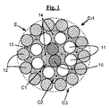
別の特定の実施形態によれば、3つのピッチp1,p2,p3は、同一ではない。これは、特に、例えば図1に概略的に示されている円筒形型のような円筒形型の層を有するコードの場合であり、この場合、3つの層C1,C2,C3は、好ましくは、同一のツイスティング方向(S/S/S又はZ/Z/Z)に巻回されているという追加の特徴を有する。 According to another particular embodiment, the three pitches p1, p2, p3 are not identical. This is particularly the case for cords having layers of cylindrical type, for example the cylindrical type schematically shown in FIG. 1, in which case the three layers C1, C2, C3 are preferably , With the additional feature of being wound in the same twisting direction (S / S / S or Z / Z / Z).
円筒形層を有するこのようなコードでは、知られているように、コンパクトさが、このようなコードの断面が例えば図1(本発明の2+8+14構造の円筒形層を有するコード)又は図2(2+8+14構造の円筒形層を有するコントロールコード、即ち、現場ゴム引きされていないコード)に示されているように多角形ではなく円筒形である輪郭を有するようなものである。 In such cords with a cylindrical layer, as is known, the compactness is such that the cross section of such a cord is, for example, FIG. 1 (cord with a cylindrical layer of the 2 + 8 + 14 structure of the invention) or FIG. Control cords having a cylindrical layer of 2 + 8 + 14 structure, i.e. cords that are not rubberized in-situ), such as having a profile that is cylindrical rather than polygonal.
第3の層又は外側層C3は、飽和層であるという好ましい特徴を有し、即ち、定義上、この層中には、直径d3の少なくとも1本の(Nmax+1)番目のワイヤを追加するに足るほどの空間が存在せず、Nmaxは、第2の層C2周りに層をなして巻回することができるワイヤの最大本数を表している。この構造は、充填ゴムがその周囲のところでにじみ出る恐れを一段と制限し、コード直径が所与の場合、高い強度をもたらすという顕著な利点を有する。 The third or outer layer C3 has the preferred feature of being a saturated layer, ie by definition it is sufficient to add at least one (Nmax + 1) th wire of diameter d3 in this layer. Nmax represents the maximum number of wires that can be wound in layers around the second layer C2. This construction has the significant advantage of further limiting the risk that the filled rubber will ooze out around it and providing high strength for a given cord diameter.
しかしながら、本発明は、外側層(C3)が非飽和層である場合にも利用できる。 However, the present invention can also be used when the outer layer (C3) is an unsaturated layer.
ワイヤの本数Nは、本発明の特定の実施形態に応じて非常に広く様々であって良く、好ましくは外側層を飽和状態に保つためにN本のワイヤの最大本数Nmaxを、これらの直径d3を第2の層のワイヤの直径d2と比較して減少させた場合、増大させることができることは言うまでもない。 The number N of wires can vary very widely depending on the particular embodiment of the invention, preferably the maximum number Nmax of N wires is set to their diameter d3 to keep the outer layer saturated. Of course, it can be increased if is reduced compared to the diameter d2 of the wire of the second layer.
好ましい実施形態によれば、第2の層(C2)は、6〜10本のワイヤを含み、第3の層(C3)は、12〜16本のワイヤを含み、上述のコードのうち、特に選択されたコードは、層C2と層C3とで同一の直径を有するワイヤから成るコードである(即ち、d2=d3)。 According to a preferred embodiment, the second layer (C2) comprises 6 to 10 wires, the third layer (C3) comprises 12 to 16 wires, The selected cord is a cord composed of wires having the same diameter in layers C2 and C3 (ie, d2 = d3).
特に好ましい実施形態によれば、第2の層(C2)は、7又は8本のワイヤを含み(即ち、Mは、7又は8に等しい)、第3の層(C3)は、13又は14本のワイヤを含み(即ち、Nは、13又は14に等しい)。本発明のコードは、特に有利な構造2+7+13及び2+8+14を有する。
According to a particularly preferred embodiment, the second layer (C2) comprises 7 or 8 wires (ie M is equal to 7 or 8) and the third layer (C3) is 13 or 14 Includes two wires (ie, N equals 13 or 14). The cord according to the invention has the particularly
本発明のコードは、任意の層状コードと同様、2つの形式のものであって良く、即ち、コンパクト型のものであっても良く円筒形層型のものであっても良い。 The cord of the present invention, like any layered cord, may be of two types, that is, a compact type or a cylindrical layer type.
好ましくは、3つの層C1,C2,C3は、同一のツイスティング方向、即ち、S方向(“S/S/S”構造)又はZ方向(“Z/Z/Z”構造)に巻回されている。これら層を同一方向に巻回することにより、有利には、これら2つの層相互間の摩擦及びこれら層を構成するワイヤの摩耗が最小限に抑えられる。 Preferably, the three layers C1, C2, C3 are wound in the same twisting direction, ie in the S direction (“S / S / S” structure) or in the Z direction (“Z / Z / Z” structure). ing. By winding the layers in the same direction, the friction between the two layers and the wear of the wires that make up the layers are advantageously minimized.
より好ましくは、3つの層は、例えば図1に示されているコードと同様円筒形層型のコードを得るために同一のツイスティング方向で且つp2及びp3が互いに同一であるにせよ互いに異なるにせよいずれにせよ、p2及び/又はp3とは異なるp1で巻回される。 More preferably, the three layers are different from each other in the same twisting direction and p2 and p3 are identical to each other, for example to obtain a cylindrical layered cord similar to the cord shown in FIG. In any case, it is wound at p1 different from p2 and / or p3.
本発明のコードの構成により、有利には、包装ワイヤを省くことができる。というのは、ゴムは、その構造中に良好に入り込み、自動包装効果を与えるからである。 The cord arrangement according to the invention advantageously makes it possible to dispense with a wrapping wire. This is because rubber penetrates well into its structure and gives an automatic packaging effect.
「金属コード」という用語は、本願における定義上、主として(即ち、これらワイヤの本数の50%を超える)又は全体が(ワイヤの100%が)金属材料で作られたワイヤで形成されているコードを意味するものと理解されたい。 The term “metal cord”, as defined herein, is a cord that is formed primarily of wires (ie, more than 50% of the number of these wires) or entirely (100% of the wires) made of a metallic material. Should be understood to mean
中央層(C1)の1本又は複数本のワイヤ、第2の層(C2)の複数本のワイヤ及び第3の層(C3)の複数本のワイヤは、互いに別個独立に又は1つの層から別の層まで、好ましくは、スチールで作られ、より好ましくは炭素鋼で作られる。しかしながら、当然のことながら、他のスチール、例えばステンレス鋼又は他の合金を用いることが可能である。 One or more wires of the central layer (C1), a plurality of wires of the second layer (C2) and a plurality of wires of the third layer (C3) may be independent of each other or from one layer Up to another layer, preferably made of steel, more preferably made of carbon steel. However, it will be appreciated that other steels such as stainless steel or other alloys can be used.
炭素鋼を用いる場合、その炭素含有量(スチールの重量を基準とした%)は、好ましくは、0.4%〜1.2%、特に0.5%〜1.1%であり、このような含有量は、タイヤに必要な機械的性質とワイヤの実現性との良好な妥協点を表している。注目されるべきこととして、0.5%〜0.6%の炭素含有量がこのようなスチールを最終的にコスト安にすることができる。というのは、このようなスチールは、延伸が容易だからである。また、本発明の別の有利な実施形態は、意図した用途に応じて、コスト安及び高いワイヤ延伸性に鑑みて、低炭素含有量、例えば0.2%〜0.5%の炭素含有量を有するスチールの使用にある。 When carbon steel is used, its carbon content (% based on the weight of the steel) is preferably 0.4% to 1.2%, in particular 0.5% to 1.1%, such as A good content represents a good compromise between the mechanical properties required for the tire and the feasibility of the wire. It should be noted that a carbon content of 0.5% to 0.6% can ultimately make such steel cheaper. This is because such steel is easy to stretch. Another advantageous embodiment of the present invention also has a low carbon content, for example a carbon content of 0.2% to 0.5%, in view of low cost and high wire drawability, depending on the intended use. The use of steel with
用いられる金属又はスチールは、特にこれが炭素鋼であるにせよステンレス鋼であるにせよ、いずれにせよ、それ自体、金属層で被覆されるのがよく、この金属層は、例えば、金属コード及び(又は)その構成要素の処理特性又はコード及び(又は)タイヤそれ自体の使用特性、例えば、付着性、耐腐食性又は耐老化性を向上させる。好ましい実施形態によれば、用いられるスチールは、真鍮(Zn−Cu合金)又は亜鉛の層で覆われる。思い起こされることとして、ワイヤの製造方法中、真鍮又は亜鉛被膜は、ワイヤの絞り成形並びにゴムへのワイヤの付着性を容易にする。しかしながら、ワイヤは、例えばこれらワイヤの耐腐食性及び(又は)ゴムへのワイヤの付着性を向上させる機能を持つ真鍮又は亜鉛以外の薄い金属層、例えば、Co、Ni、Al又は元素Cu、Zn、Al、Ni、Co、Snのうち2つ以上の合金の薄い層で覆われても良い。 The metal or steel used, in particular whether it is carbon steel or stainless steel, can itself be coated with a metal layer, which can be, for example, a metal cord and ( Or) improve the processing characteristics or cords of the component and / or the use characteristics of the tire itself, such as adhesion, corrosion resistance or aging resistance. According to a preferred embodiment, the steel used is covered with a layer of brass (Zn—Cu alloy) or zinc. Recall that during the wire manufacturing process, the brass or zinc coating facilitates drawing of the wire as well as adhesion of the wire to rubber. However, the wires are, for example, thin metal layers other than brass or zinc that have the function of improving the corrosion resistance of these wires and / or the adhesion of the wires to rubber, for example Co, Ni, Al or the elements Cu, Zn , Al, Ni, Co, Sn may be covered with a thin layer of two or more alloys.
本発明のコードは、好ましくは、炭素鋼で作られ、好ましくは2,500MPa以上、より好ましくは3,000MPa以上の引張強さ(Rm)を有する。本発明のコードの各構成要素としてのストランドの破断点全伸び率(Atで表される)、即ち、その構造伸び率、弾性伸び率及び塑性伸び率の合計は、好ましくは、2.0%以上であり、より好ましくは少なくとも2.5%に等しい。 The cord of the present invention is preferably made of carbon steel and preferably has a tensile strength (Rm) of 2,500 MPa or more, more preferably 3,000 MPa or more. The total elongation at break (expressed by At) of the strand as each component of the cord of the present invention, that is, the sum of the structural elongation, elastic elongation and plastic elongation is preferably 2.0%. And more preferably at least equal to 2.5%.
充填ゴムのエラストマー(又は区別なく言えば「ゴム」、これら2つの用語は、同義語であると見なされる)は、好ましくは、ジエンエラストマー、即ち、定義上、少なくとも一部(即ち、ホモポリマー又はコポリマー)がジエンモノマー(即ち、2つの共役又は違った仕方の炭素‐炭素二重結合を備えたモノマー)に由来するエラストマーである。ジエンエラストマーは、より好ましくは、ポリブタジエン(BR)、天然ゴム(NR)、合成ポリイソプレン(IR)、種々のブタジエンコポリマー、種々のイソプレンコポリマー、及びこれらエラストマーの混合物から成る群から選択される。このようなコポリマーは、より好ましくは、ブタジエン‐スチレンコポリマー(SBR)(乳化重合(ESBR)によって調製されるにせよ溶液重合(SSBR)によって調製されるにせよ、いずれにせよ)、ブタジエン‐イソプレンコポリマー(BIR)、スチレン‐イソプレンコポリマー(SIR)及びスチレン‐ブタジエン‐イソプレンコポリマー(SBIR)から成る群から選択される。 The elastomers of the filled rubber (or “rubber”, interchangeably, these two terms are considered synonymous) are preferably diene elastomers, ie, at least partly (ie, homopolymers or Copolymer) is an elastomer derived from a diene monomer (ie, a monomer with two conjugates or different ways of carbon-carbon double bonds). The diene elastomer is more preferably selected from the group consisting of polybutadiene (BR), natural rubber (NR), synthetic polyisoprene (IR), various butadiene copolymers, various isoprene copolymers, and mixtures of these elastomers. Such copolymers are more preferably butadiene-styrene copolymers (SBR) (whether prepared by emulsion polymerization (ESBR) or by solution polymerization (SSBR)), butadiene-isoprene copolymers (BIR), styrene-isoprene copolymer (SIR) and styrene-butadiene-isoprene copolymer (SBIR).
好ましい一実施形態は、「イソプレン」エラストマー、即ち、イソプレンのホモポリマー又はコポリマー、換言すると、天然ゴム(NR)、合成ポリイソプレン(IR)、種々のイソプレンコポリマー及びこれらエラストマーの混合物から成る群から選択されたジエンエラストマーを用いることから成る。イソプレンエラストマーは、好ましくは、天然ゴム又はシス−1,4系の合成ポリイソプレンである。これら合成ポリイソプレンのうち、好ましくは、シス−1,4結合の含有量(モル%)が90%以上、より好ましくは98%以上のポリイソプレンが用いられる。他の好ましい実施形態によれば、イソプレンエラストマーを別のジエンエラストマー、例えばSBR系及び/又はBR系のエラストマーと組み合わせても良い。 One preferred embodiment is selected from the group consisting of “isoprene” elastomers, ie homopolymers or copolymers of isoprene, in other words natural rubber (NR), synthetic polyisoprene (IR), various isoprene copolymers and mixtures of these elastomers. Using a modified diene elastomer. The isoprene elastomer is preferably natural rubber or cis-1,4 synthetic polyisoprene. Among these synthetic polyisoprenes, polyisoprene having a cis-1,4 bond content (mol%) of preferably 90% or more, more preferably 98% or more is used. According to other preferred embodiments, the isoprene elastomer may be combined with another diene elastomer, such as an SBR-based and / or BR-based elastomer.
充填ゴムは、好ましくは架橋可能であり、即ち、充填ゴムは、一般に、配合物の硬化中(即ち、溶融ではなく、ハードニング中)、配合物を架橋することができるのに適した架橋系から成る。このような場合、このゴムコンパウンドは、どのような温度に加熱してもこれを溶融させることができないので、「溶融不能」と呼ばれる場合がある。好ましくは、ジエンゴムコンパウンドの場合、このゴムシースの架橋系は、加硫系であり、即ち、硫黄(又は硫黄ドナー)及び少なくとも1種類の加硫促進剤を主成分としている。種々の公知の加硫活性剤をこの基本加硫系に添加するのがよい。硫黄は、0.5〜10phr、より好ましくは1〜8phrの好ましい量で用いられ、加硫促進剤、例えば、スルフェンアミド(sulphenamide)は、好ましくは0.5〜10phr、より好ましくは0.5〜5.0phrの量で用いられる。 The filled rubber is preferably crosslinkable, i.e., the filled rubber is generally a crosslinking system suitable to allow the formulation to be crosslinked during curing of the formulation (i.e. during hardening rather than melting). Consists of. In such a case, the rubber compound may be referred to as “unmeltable” because it cannot be melted at any temperature. Preferably, in the case of a diene rubber compound, the rubber sheath cross-linking system is a vulcanization system, i.e., based on sulfur (or a sulfur donor) and at least one vulcanization accelerator. Various known vulcanization activators may be added to this basic vulcanization system. Sulfur is used in a preferred amount of 0.5 to 10 phr, more preferably 1 to 8 phr, and a vulcanization accelerator such as sulphenamide is preferably 0.5 to 10 phr, more preferably 0.8. Used in an amount of 5 to 5.0 phr.
充填ゴムは、上述の架橋系とは別に、タイヤの製造向きのゴム母材中に通常用いられる添加剤、例えば、補強充填剤、例えばカーボンブラック又は無機充填剤、例えばシリカ、結合剤、老化防止剤、酸化防止剤、可塑化剤、又はエキステンダ油(後者は、性質上芳香性であるにせよ非芳香性であるにせよ、いずれにせよ)(特に、ほんの僅かに芳香性であり或いは全く芳香性ではない油、例えば、粘度の高い又は好ましくは低いナフテン系の油又はパラフィン系の油、MES又はTDAE油))、30℃よりも高いTgの可塑化樹脂、非硬化状態の組成物の処理(処理性)を容易にする作用剤、粘着性樹脂、加硫戻り防止剤、メチレン受容体及び供与体、例えばHMT(ヘキサメチレンテトラミン)又はH3M(ヘキサメトキシメチルメラミン)、補強樹脂(例えばレソルチノール又はビスマレイミド)、金属塩、特にコバルト又はニッケル塩タイプの公知の密着性促進(定着)系のうち全て又は幾つかを更に含むのが良い。 In addition to the above-mentioned crosslinking system, the filler rubber is an additive usually used in a rubber base material for tire production, such as a reinforcing filler, such as carbon black or an inorganic filler, such as silica, a binder, anti-aging. Agents, antioxidants, plasticizers, or extender oils (the latter being either aromatic or non-aromatic in nature, either) (especially only slightly aromatic or not at all) Non-aromatic oils, such as highly viscous or preferably low naphthenic or paraffinic oils, MES or TDAE oils)), Tg plasticizers higher than 30 ° C., uncured compositions Agents that facilitate processing (processability), adhesive resins, anti-reversion agents, methylene acceptors and donors, such as HMT (hexamethylenetetramine) or H3M (hexamethoxymethyl melamine) ), Reinforcing resins (e.g. Resoruchinoru or bismaleimide), metal salts, especially cobalt or nickel salt type known adhesion promoting (fixing) further better contain all or some of the system.
補強充填材、例えば、カーボンブラック又は補強無機充填材、例えばシリカの量は、好ましくは、50phr以上、例えば、50〜120phrである。この量は、より好ましくは、70phr以上、例えば70〜120phrである。カーボンブラックに関し、例えば、特にタイヤに従来用いられていたタイプHAF、ISAF及びSAFのあらゆるカーボンブラック(タイヤ用ブラックと呼ばれている)が適している。これらのうちで、ASTM300、600又は700等級のカーボンブラック(例えば、N326、N330、N347、N375、N683、N772)が特に挙げられる。適当な無機補強充填材は、特に、シリカ(SiO2)系の鉱物充填材であり、特に、BET表面積が450m2/g以下、好ましくは30〜400m2/gの沈降又は熱分解法シリカである。
The amount of reinforcing filler, for example carbon black or reinforcing inorganic filler, for example silica, is preferably 50 phr or more, for example 50 to 120 phr. This amount is more preferably 70 phr or more, for example 70 to 120 phr. With regard to carbon black, for example, all types of carbon black of type HAF, ISAF and SAF conventionally used for tires (referred to as tire black) are suitable. Among these, ASTM 300, 600 or 700 grade carbon black (eg, N326, N330, N347, N375, N683, N772) is specifically mentioned. Suitable inorganic reinforcing fillers, in particular silica (SiO2) based a mineral filler, in particular, BET surface area of 450 m 2 / g or less, it is preferably precipitated or
当業者であれば、本明細書の説明に照らして、充填ゴムの処方を調整することができ、その目的は、所望レベルの特性(特に、弾性モジュラス)を達成すると共に処方を特定の意図した用途に適合させることにある。 One skilled in the art can tailor the formulation of the filled rubber in light of the description herein, the purpose of which is to achieve the desired level of properties (particularly the elastic modulus) and to specifically formulate the formulation. The purpose is to adapt to the application.
本発明の第1の実施形態によれば、充填ゴムの調合は、本発明のコードが補強しようとしているゴム母材の処方と同一であるように選択される。充填ゴムの材料と上述のゴム母材の材料との間には適合性に関する問題はない。 According to the first embodiment of the present invention, the filling rubber formulation is selected so that the cord of the present invention is identical to the prescription of the rubber base material to be reinforced. There is no compatibility problem between the filled rubber material and the rubber matrix material described above.
本発明の第2の実施形態によれば、充填ゴムの調合は、本発明のコードが補強するようになったゴム母材の調合とは異なるよう選択されるのが良い。充填ゴムの調合は、特に、比較的多量の定着剤、代表的には例えば5〜15phrの金属塩、例えばコバルト塩、ニッケル塩又はネオジミウム塩を用いることにより、そして、有利には、周りのゴム母材中の上述の定着剤の量を減少させる(或いは、それどころかこれを完全に無くす)ことにより調整されるのが良い。当然のことながら、充填ゴムの粘度及びコードが製造されているときにコードに入り込むその能力を最適化するために充填ゴムの調合を調節することも可能である。 According to the second embodiment of the invention, the filling rubber formulation may be selected to be different from the rubber matrix formulation that the cord of the present invention is reinforced. Filling rubber formulations are particularly advantageous by using relatively large amounts of fixing agents, typically 5-15 phr metal salts such as cobalt, nickel or neodymium salts, and advantageously the surrounding rubber. Adjustments may be made by reducing the amount of the fixer described above in the matrix (or even eliminating it entirely). Of course, it is also possible to adjust the filling rubber formulation to optimize the viscosity of the filling rubber and its ability to penetrate the cord as it is being manufactured.
好ましくは、充填ゴムは、架橋状態では、E10(10%伸び率における)割線引張モジュラスが、2〜25MPa、より好ましくは3〜20MPa、特に3〜15MPaである。 Preferably, the filled rubber has an E10 (at 10% elongation) secant tensile modulus in the crosslinked state of 2 to 25 MPa, more preferably 3 to 20 MPa, especially 3 to 15 MPa.
本発明は、当然のことながら、未硬化状態(充填ゴムが架橋されていない)及び硬化状態(充填ゴムが加硫されている)の両方における上述のストランドコードに関する。しかしながら、未硬化状態の充填ゴムを備えた本発明のストランドコードを使用し、次に、充填ゴム最終架橋又は加硫中、充填ゴムと周囲のゴムマトリックス(例えば、圧延ゴム)との結合を促進するようストランドコードの設計対象の半完成品又は完成品、例えばタイヤに組み込まれることが好ましい。 The present invention, of course, relates to the above-described strand cords both in the uncured state (the filled rubber is not crosslinked) and in the cured state (the filled rubber is vulcanized). However, the strand cord of the present invention with uncured filled rubber is used, and then promotes the bond between the filled rubber and the surrounding rubber matrix (eg, rolled rubber) during the final rubber crosslinking or vulcanization. Thus, it is preferably incorporated into a semi-finished product or a finished product, for example, a tire, for which the strand cord is designed.
図1は、本発明の好ましい2+8+14コードの一例をコード(これは、真っ直ぐであると共に休止状態であると仮定される)の軸線に垂直な断面で概略的に示している。 FIG. 1 schematically shows an example of a preferred 2 + 8 + 14 cord of the present invention in a cross section perpendicular to the axis of the cord (which is assumed to be straight and dormant).
このコード(C‐1で示されている)は、円筒形層型のものであり、即ち、その第1、第2及び第3の層(それぞれ、C1,C2,C3)は、互いに異なるピッチで又は互いに異なるツイスティング方向で巻回されている。この種の構造は、その第2及び第3の層(C2,C3)のワイヤ(それぞれ、11,12)が第1の層(C1)の2本のワイヤ(10)の周りに、各々がいわゆるコンパクト層型のコードの場合のように多角形(より具体的に言えば、六角形)ではなく、実質的に円筒形である輪郭(E)(点線で示されている)を有する2つの実質的に円筒形層を形成するという作用効果を有する。 This cord (indicated by C-1) is of the cylindrical layer type, ie its first, second and third layers (C1, C2, C3, respectively) have different pitches. Or in different twisting directions. This type of structure has its second and third layer (C2, C3) wires (11, 12 respectively) around the two wires (10) of the first layer (C1), each Two having an outline (E) (shown in dotted lines) that is substantially cylindrical rather than polygonal (more specifically, hexagonal) as in the case of so-called compact layered cords. This has the effect of forming a substantially cylindrical layer.
この図1から理解できるように、充填ゴム(13)は、ワイヤを非常に僅かではあるが分けた状態で一方において第1の層(C1)の2本のワイヤ(10)及び第2の層(C2)のM本のワイヤ(11)により、他方、第2の層(C2)のM本のワイヤ(11)及び第3の層(C3)のN本のワイヤ(12)により画定された毛管又は隙間(14)(一例を挙げると、これらのうちの幾つかは三角形で示されている)の各々を少なくとも部分的に充填し、これらワイヤは、少なくとも3本の隣り合うワイヤ(この場合、図1に示されている毛管又は隙間の例によれば3本、4本、5本又は6本)から成る群の状態であると考えられる。 As can be seen from FIG. 1, the filled rubber (13) has two wires (10) and a second layer of the first layer (C1) on the one hand, with the wires separated very little. Defined by M wires (11) in (C2), on the other hand, by M wires (11) in the second layer (C2) and N wires (12) in the third layer (C3) At least partially fill each of the capillaries or gaps (14, some of which are shown as triangles, to name one example), and these wires are at least three adjacent wires (in this case According to the example of the capillary or the gap shown in FIG. 1, it is considered that the state is a group consisting of 3, 4, 5 or 6).
好ましい実施形態によれば、本発明のコードでは、充填ゴムは、好ましくは、これが覆っている第2の層(C2)の周りに連続して延びる。 According to a preferred embodiment, in the cord according to the invention, the filling rubber preferably extends continuously around the second layer (C2) that it covers.
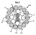
比較すると、図2は、これ又コンパクト型の従来型2+8+14コード(C‐2で示され(即ち、現場でゴム引きされていない)、円筒形層型の場合(円筒形輪郭E)と同様、3つの層(C1,C2,C3)を有するコード)の残部を断面で示している。この種のコードの特徴は、その種々のワイヤが多くのチャネル又は毛管(14)を形成し、これらチャネル又は毛管は、閉鎖されると共に空のままであり、従って「吸い上げ」効果により腐食性媒体、例えば水の伝搬に都合が良い。 In comparison, FIG. 2 shows that this is also a compact conventional 2 + 8 + 14 cord (shown as C-2 (ie not rubberized in the field)), as in the case of the cylindrical layer type (cylindrical contour E) The remainder of the three layers (cord with C1, C2, C3) is shown in cross section. A feature of this type of cord is that the various wires form a number of channels or capillaries (14) that are closed and remain empty, and thus a “sucking” effect due to the corrosive medium. For example, it is convenient for water propagation.
本発明のコードは、例えば、このコードの周りに外側層(C3)のピッチよりも短いピッチで且つこの外側層の巻回方向とは逆の又は同じ巻回方向で螺旋状に巻回された単一の金属又は非金属細線から成る外部包装体(ラッパ)を備えても良い。しかしながら、既に自動包装されている本発明のコードは、その特別な構造に鑑みて、外側包装細線の仕様を必要とせず、これは、有利には、包装体とコードの最も外側の層のワイヤとの間の摩耗の問題を解決する。 For example, the cord of the present invention is spirally wound around the cord at a pitch shorter than the pitch of the outer layer (C3) and in a direction opposite to or equal to the winding direction of the outer layer. You may provide the outer package body (wrapper) which consists of a single metal or a nonmetallic fine wire. However, the cord of the present invention which has already been automatically packaged does not require the specification of the outer wrapping wire in view of its special structure, which is advantageously the wire of the outermost layer of the wrapping and cord. To solve the wear problem between.
しかしながら、包装細線が用いられる場合、外側層のワイヤが炭素鋼で作られている一般的な場合、有利には、例えば国際公開第98/41682号パンフレットによって教示されているようにステンレス鋼包装体(ラッパ)と接触状態にあるこれら炭素鋼ワイヤのフレッチング摩耗を減少させるためにステンレス鋼で作られた包装細線を選択するのが良く、オプションとして、ステンレス鋼ワイヤに代えて、均等例として、欧州特許出願公開第976541(A)号明細書に記載されているように外層がステンレス鋼で作られ、コアが炭素鋼で作られている複合ワイヤを用いることが可能である。また、国際公開第03/048447号パンフレットに記載されているようにポリエステル又はサーモトロピック芳香族ポリエステルアミドで作られた包装体を用いることが可能である。 However, when wrapping wires are used, the general case where the outer layer wires are made of carbon steel is advantageously a stainless steel package, for example as taught by WO 98/41682. In order to reduce the fretting wear of these carbon steel wires in contact with the trumpet, it is better to choose a wrapping wire made of stainless steel, and as an option, instead of stainless steel wire, an equivalent example is European It is possible to use a composite wire in which the outer layer is made of stainless steel and the core is made of carbon steel, as described in patent application 976541 (A). Further, it is possible to use a package made of polyester or thermotropic aromatic polyester amide as described in WO 03/048447.
当業者であれば理解されるように、上述の本発明のコードで用いられるストランドは、オプションとして、ジエン以外のエラストマー、特に熱可塑性エラストマー(TPE)、例えばポリウレタン(TPU)エラストマーを主成分とする充填ゴムで現場ゴム引きされる場合があり、このようなエラストマーは、知られているように、架橋され又は加硫されることが必要ではなく、常用温度では、加硫後のジエンエラストマーの特性とほぼ同じ特性を有する。 As will be appreciated by those skilled in the art, the strands used in the cords of the invention described above are optionally based on elastomers other than diene, in particular thermoplastic elastomers (TPE), such as polyurethane (TPU) elastomers. Filled rubber may be in-situ rubberized, and such elastomers do not need to be cross-linked or vulcanized, as is known, and at normal temperatures the properties of diene elastomers after vulcanization Have almost the same characteristics.
しかしながら、特に好ましくは、本発明は、このようなエラストマーに特に適した特定の製造プロセスを特に用いて上述のジエンエラストマーを主成分とする充填ゴムについて実施され、この製造プロセスについて以下に詳細に説明する。 However, it is particularly preferred that the present invention is carried out on filled rubbers based on the aforementioned diene elastomers, in particular using a specific manufacturing process particularly suitable for such elastomers, and this manufacturing process is described in detail below. To do.
II‐2.本発明のコードの製造
好ましくはジエンエラストマーを用いて現場ゴム引きされた本発明の上述のコードは、好ましくはインラインで且つ連続的に実施される以下のステップを含む方法を用いて製造されるのが良い。
‐中央層の2本のワイヤをツイスティングして「第1の組み立て箇所」と呼ばれている第1の箇所のところに第1の層又は中央層(C1)を形成する第1の組み立てステップを有し、
‐M本のワイヤを中央層(C1)の周りにツイスティングして「第2の組み立て箇所」と呼ばれる第2の箇所に、2+M構造の「コアストランド」と呼ばれる中間コード(C1+C2)を形成する第2の組み立てステップを有し、
‐第1の組み立て箇所の下流側において、中央層(C1)及び/又はコアストランド(C1+C2)を未硬化状態の充填ゴムで外装する外装ステップ、外装は、第2の組み立て箇所の上流側か下流側かのいずれか又は上流側と下流側の両方で実施され、
‐次に、N本のワイヤを外装されたコアストランドの周りにツイスティング又はケーブリングすることによる第3の組み立てステップを有し、
‐次に最終の撚りバランス取りステップを有する。
II-2. Production of the Cord of the Invention The above-described cord of the present invention, preferably rubberized in situ with a diene elastomer, is preferably produced using a method comprising the following steps performed in-line and continuously. Is good.
A first assembly step in which the two wires of the central layer are twisted to form the first layer or the central layer (C1) at a first location called the “first assembly location” Have
-Twist M wires around the central layer (C1) to form an intermediate cord (C1 + C2) called "core strand" with a 2 + M structure at a second location called "second assembly location" Having a second assembly step;
-On the downstream side of the first assembly location, an exterior step of exteriorizing the central layer (C1) and / or core strand (C1 + C2) with uncured filled rubber, the exterior is upstream or downstream of the second assembly location Carried out either on either side or both upstream and downstream,
-Next, a third assembly step by twisting or cabling N wires around the sheathed core strand,
-Next has a final twist balancing step.
好ましくは、充填ゴムによる外装ステップは、第1の組み立て箇所の下流側で且つ第2の組み立て箇所の上流側で中央層(C1)にのみ行われ、充填ゴムは、本発明のコードを得るのに十分な量で単一ショットで送り出される。実施形態の考えられる一変形形態では、第2の組み立て箇所の下流側で、コアストランド(C1+C2)を外装する追加のステップを実施する。しかしながら、外装ステップを1回だけ用いることが好ましい。 Preferably, the exterior step with filled rubber is performed only on the central layer (C1) downstream of the first assembly location and upstream of the second assembly location, the filled rubber obtaining the cord of the present invention. It is sent out in a single shot with a sufficient amount. In one possible variation of the embodiment, an additional step of sheathing the core strand (C1 + C2) is performed downstream of the second assembly location. However, it is preferable to use the exterior step only once.
ここで思い起こされるように、金属ワイヤを組み立てるための2つの考えられる技術、即ち、
‐ケーブリング(cabling)(このような場合、ワイヤは、組み立て箇所の前後における同期回転に鑑みてこれら自身の軸線回りの撚りを示さない)、
‐又は、ツイスティング(twisting)(このような場合、ワイヤは、一括的な撚りとこれら自身の軸線回りの個々の撚りの両方を示し、それによりワイヤの各々にはアンツイスティング(撚りをほどく)トルクが生じる)が存在する。
As recalled here, there are two possible techniques for assembling metal wires:
-Cabling (in which case the wires do not show twists about their own axis in view of the synchronous rotation before and after the assembly),
-Or twisting (in such a case, the wire exhibits both a collective twist and individual twists around its own axis so that each of the wires is untwisted (untwisted). ) Torque is generated).
上述の方法の本質的な一特徴は、第2の層(C2)をコア(C1)の周りに組み立てると共に第3の層(C3)を第2の層(C2)の周りに組み立てるツイスティングステップの使用にある。 An essential feature of the above-described method is that a twisting step of assembling the second layer (C2) around the core (C1) and assembling the third layer (C3) around the second layer (C2). Is in use.
第3の層(C3)は、ツイスティング又はケーブリングにより第2の層(C2)周りに組み立てられるのが良い。例えば最初の2回の組み立て作業(層C1,C2)についてはツイスティング作業を用いることが好ましい。 The third layer (C3) may be assembled around the second layer (C2) by twisting or cabling. For example, it is preferable to use a twisting operation for the first two assembly operations (layers C1 and C2).
第3の層(C3)をケーブリングにより組み立てる場合、コードを好ましくは、2つの非連続ステップ(最初の2つの層のツイスティング、次に第3の層のケーブリング)で製造し、この場合、2回の外装ステップ(即ち、中央層(C1)の第1の外装、コアストランド(C1+C2)に対する後の第2の外装)を用いることが好ましい。 When the third layer (C3) is assembled by cabling, the cord is preferably manufactured in two non-consecutive steps (first two layers twisting, then third layer cabling), It is preferable to use two exterior steps (that is, the first exterior of the central layer (C1), the second exterior after the core strand (C1 + C2)).
一例を挙げると、手順は次の通りである。
第1のステップの際、中央層の2本のワイヤを一緒にツイスティングして(S又はZ方向)それ自体知られている仕方で第1の層(C1)を形成し、2本のワイヤを共通ツイスティング箇所(又は第1の組み立て箇所)に収斂させるようになった組み立てガイドに結合されても良く又は結合されていなくても良い供給手段、例えばスプール、分離格子によってワイヤを送り出す。
As an example, the procedure is as follows.
During the first step, the two wires of the central layer are twisted together (S or Z direction) to form the first layer (C1) in a manner known per se, and the two wires Are fed by means of a supply, such as a spool, a separation grid, which may or may not be coupled to an assembly guide adapted to converge at a common twisting location (or first assembly location).
先のステップの終了時、第2の層(C2)のM本のワイヤを中央層(C1)周りに一緒にツイスティングし(S方向又はZ方向)コアストランド(C1+C2)を形成し、中央層のワイヤについては従前通り、M本のワイヤを共通ツイスティング箇所(又は第2の組み立て箇所)に収斂させるようになった組み立てガイドに結合されても良く又は結合されていなくても良い供給手段、例えばスプール、分離格子によって第2の層のワイヤを送り出す。 At the end of the previous step, the M wires of the second layer (C2) are twisted together around the central layer (C1) (S direction or Z direction) to form the core strand (C1 + C2) As for the wire, the supply means which may or may not be coupled to the assembly guide adapted to converge the M wires at the common twisting location (or the second assembly location), as before. For example, the wire of the second layer is sent out by a spool or a separation grid.
次に、このように形成されたコア(C1+C2)を適当な温度で押し出しスクリューにより供給された未硬化充填ゴムで外装する。充填ゴムを単一押し出しヘッドによって単一且つ小容量固定箇所のところで送り出すのが良い。 Next, the core (C1 + C2) thus formed is covered with uncured filled rubber supplied by an extrusion screw at an appropriate temperature. The filled rubber is preferably sent out at a single small-capacity fixed point by a single extrusion head.
押し出しヘッドは、1つ又は2つ以上のダイ、例えば、上流側案内ダイ及び下流側サイジングダイを有するのが良い。コードの直径を連続的に測定すると共に制御する手段を追加するのが良く、これらは、押し出し機に連結される。好ましくは、充填ゴムの押し出し温度は、50℃〜120℃、より好ましくは50℃〜100℃である。 The extrusion head may have one or more dies, such as an upstream guide die and a downstream sizing die. Means may be added to continuously measure and control the diameter of the cord, which are connected to the extruder. Preferably, the extrusion temperature of the filled rubber is 50 ° C to 120 ° C, more preferably 50 ° C to 100 ° C.
押し出しヘッドは、例えば中央層(C1)に対して外装ステップが1回だけ実施される好ましい場合、回転筒体の形状を備えた外装ゾーンを構成し、その直径は、好ましくは、0.15mm〜1.2mm、より好ましくは0.2〜1.0mmであり、その長さは、好ましくは、4〜10mmである。 The extrusion head, for example, constitutes an exterior zone having the shape of a rotating cylinder when the exterior step is performed only once on the central layer (C1), and the diameter thereof is preferably 0.15 mm to The length is 1.2 mm, more preferably 0.2 to 1.0 mm, and the length is preferably 4 to 10 mm.
押し出しヘッドにより送り出される充填ゴムの量は、最終の(即ち、製造完了後の現場ゴム引きされた)コード1グラム当たり10〜50mgの好ましい範囲、特に5〜30mgの範囲内で調節される。 The amount of filled rubber delivered by the extrusion head is adjusted within a preferred range of 10 to 50 mg, especially in the range of 5 to 30 mg per gram of final (ie field rubberized after completion of production) cord.
指定した最小値を下回る場合、充填ゴムがコードの毛管又は隙間の各々の中に確かに存在するようにすることは可能ではなく、これに対し、指定した最大値を上回る場合、コードは、本発明の特定の作用条件及び製造されるコードの特定の構造に応じて、充填ゴムがコードの周囲のところでにじみ出し(オーバースピル)を生じることに起因した上述の種々の問題を生じる場合がある。これらの理由の全てにより、充填ゴム含有量は、好ましくはコード1g当たり15〜45mg、より好ましくはコード1g当たり15〜40mgである。 It is not possible to ensure that the filled rubber is present in each of the cord capillaries or gaps below the specified minimum value, whereas if the specified maximum value is exceeded, the cord Depending on the specific operating conditions of the invention and the specific structure of the cord produced, the various problems described above may result from the filled rubber causing spilling around the cord (overspill). For all of these reasons, the filled rubber content is preferably 15-45 mg / g cord, more preferably 15-40 mg / g cord.
組み立て箇所の下流側では、コアストランドに加わる引張応力は、好ましくはその破断強さの10〜25%である。 On the downstream side of the assembly location, the tensile stress applied to the core strand is preferably 10-25% of its breaking strength.
中央層(C1)について実施される単一外装ステップの好ましい場合、コードの中央層をこれが押し出しヘッドを出るときにその周囲の全ての箇所のところが好ましくは、20μmを超え、より好ましくは30μmを超え、特に30〜80μmの最小厚さの充填ゴムで被覆する。 In the preferred case of a single sheathing step carried out on the central layer (C1), the central layer of the cord is preferably more than 20 μm, more preferably more than 30 μm all around it as it exits the extrusion head. In particular, it is coated with a filled rubber with a minimum thickness of 30 to 80 μm.
第3のステップの際、第3の層又は外側層(C3)のP本のワイヤを、この場合も又、上述のように外装されたコアストランド(C1+C2)の周りにツイスティングする(S又はZ方向に)ことによって最終的に組み立てる。 During the third step, the P wires of the third or outer layer (C3) are again twisted around the core strand (C1 + C2) sheathed as described above (S or In the Z direction).
プロセス中のこの段階においては、本発明のコードは、完成されておらず、第2の層(C2)のM本のワイヤ及び第3の層(C3)のN本のワイヤによって画定された上記毛管は、まだ充填ゴムで一杯にはなっておらず、或いは、どの場合であっても、空気の最適不透過性のコードを得るのに十分な充填状態にはない。 At this stage in the process, the cord of the present invention was not completed and was defined by the M wires in the second layer (C2) and the N wires in the third layer (C3). The capillaries are not yet full of filled rubber, or in any case are not sufficiently filled to obtain an optimally impermeable cord of air.
重要な次のステップでは、未硬化状態の充填ゴムを備えたコードを撚りバランス取りされた(即ち、実際に残留ねじりがない状態)と言えるコードが得られるようにするために、撚りバランス取り手段に通し、「撚りバランス取り」という用語は、この場合、公知のように、それぞれの層内のツイスティング状態にあるコードの各ワイヤに及ぼされる残留ツイスティングトルク(又は解撚又はアンツイスティングスプリングバック)の打ち消しを意味しているものと理解されたい。撚りバランス取りツールは、ツイスティング技術における当業者には周知であり、これら撚りバランス取りツールは、例えば、ストレートナ及び/又は「ツイスタ」及び/又は「ツイスタ‐ストレートナ」から成る場合があり、これらは、ツイスタの場合にはプーリかストレートナの場合には小径ローラかのいずれかを有し、コードは、単一の平面又は好ましくは少なくとも2つの互いに異なる平面内でプーリ又はローラを通って走行する。 In an important next step, a twist balancing means is used in order to obtain a cord that can be said to be twisted and balanced (i.e., in fact no residual twist) with the uncured filled rubber. The term “twist balancing” is used here to refer to the residual twisting torque (or untwisting or untwisting spring) that is applied to each wire of the cord in twisted state in each layer, as is known in the art. It should be understood that this means canceling back. Twist balancing tools are well known to those skilled in the twisting art, and these twist balancing tools may comprise, for example, straighteners and / or “twisters” and / or “twister-straighteners”; These have either pulleys in the case of twisters or small diameter rollers in the case of straighteners, and the cords pass through the pulleys or rollers in a single plane or preferably in at least two different planes. Run.
経験上、上述の種々のバランス取り手段の通過中、バランス取り手段は、第2及び第3の層(C2,C3)のN本及びP本のワイヤに加わる撚り及び半径方向圧力を生じさせ、このような撚り及び半径方向圧力は、依然として高温であり且つ比較的流動的な未硬化(即ち、未架橋、未加工)状態の充填ゴムを中央層(C1)及び第2の層(C2)のN本のワイヤで形成された毛管から第2の層(C2)のN本のワイヤ及び第3の層(C3)のP本のワイヤで形成された毛管中に部分的に移送することによってこのような充填ゴムを再分配するのに十分であり、最終的に、本発明のコードにこれを特徴付ける優れた通気度特性を与える。また、矯正又はくせ取りツールを用いることによって提供される矯正機能は、ストレートナのローラと第3の層(C3)のワイヤの接触により、充填ゴムに追加の圧力が及ぼされ、充填ゴムが更にコードの第2の層(C2)と第3の層(C3)との間に存在する毛管に十分に侵入するようになるという利点を有する。 Experience has shown that during the passage of the various balancing means described above, the balancing means creates twist and radial pressure on the N and P wires of the second and third layers (C2, C3), Such twists and radial pressures cause the filled rubber in the uncured (i.e. uncrosslinked, unprocessed) state to remain in the hot and relatively fluid state of the central layer (C1) and the second layer (C2). This is achieved by partially transferring from the capillary formed of N wires into the capillary formed of N wires of the second layer (C2) and P wires of the third layer (C3). It is sufficient to redistribute such filled rubbers, and ultimately gives the cords of the present invention excellent air permeability characteristics that characterize it. Further, the correction function provided by using the correction or combing tool is that the pressure of the filler rubber is further increased by the contact between the straightener roller and the wire of the third layer (C3). It has the advantage that it will fully penetrate the capillaries that exist between the second layer (C2) and the third layer (C3) of the cord.
換言すると、上述の本発明のプロセスは、充填ゴムをコードの内部に半径方向に分布すると同時に供給される充填ゴムの量を完全に制御するようコードの最終製造段階においてワイヤの撚り及びワイヤに及ぼされる半径方向圧力を用いる。当業者であれば、特に、ワイヤに及ぼされる半径方向圧力の強度を変化させる目的で撚りバランス取り手段のプーリ及び/又はローラの配置及び直径の調節の仕方について知っているであろう。 In other words, the process of the present invention described above extends to the wire strands and wires in the final manufacturing stage of the cord so as to completely control the amount of filler rubber supplied while simultaneously distributing the filler rubber radially within the cord. Use radial pressure. The person skilled in the art will know how to adjust the arrangement and diameter of the pulleys and / or rollers of the twist balancing means, in particular for the purpose of changing the strength of the radial pressure exerted on the wire.
予期せぬこととして、第1の層又は中央層(C1)の形成のために2本のワイヤの第1の組み立て箇所の下流側でゴムを被着させると同時に単一押し出しヘッドの使用により送り出される充填ゴムの量を制御すると共に最適化することにより、充填ゴムを本発明のコードのまさに心臓部中にそしてその毛管の全ての中に侵入させることが可能であることが判明した。 Unexpectedly, the rubber is deposited downstream of the first assembly point of the two wires for the formation of the first layer or the central layer (C1) and at the same time delivered by the use of a single extrusion head. It has been found that by controlling and optimizing the amount of filled rubber that is applied, it is possible to allow the filled rubber to penetrate into the very heart of the cord of the present invention and into all of its capillaries.
この最終撚りバランス取りステップ後においては、本発明の方法によるコードの製造は、コードが未硬化充填ゴムで現場でゴム引きされた状態で、完了している。 After this final twist balancing step, the manufacture of the cord according to the method of the present invention is complete with the cord being rubberized in situ with uncured filled rubber.
好ましくは、この完成後のコードでは、コードの隣り合うワイヤ(これらワイヤがどれであるにせよ、特に、中央層(C1)の2本ワイヤ相互間)相互間の充填ゴムの厚さは、1μmを超え、好ましくは1〜10μmである。このコードを貯蔵のために受け入れスプールに巻き付けるのが良く、その後、例えば、例えばタイヤカーカス補強材として使用でき又は変形例としてマルチストランドロープ中へ組み込むことができる金属/ゴム複合ファブリックを調製するために、圧延設備によりこのコードを処理する。 Preferably, in this completed cord, the thickness of the rubber filling between the adjacent wires of the cord (whatever these wires are, especially between the two wires of the central layer (C1)) is 1 μm. And preferably 1 to 10 μm. To prepare a metal / rubber composite fabric that can be wound on a receiving spool for storage and then used, for example, as a tire carcass reinforcement or can be incorporated into a multi-strand rope as a variant. Process this code with rolling equipment.
今説明したばかりの製造法の実施形態の別の形態では、中央層(C1)それ自体に対して、即ち、第2の組み立て箇所の下流側ではなく上流側で外装ステップを実施するのが良い。次に、生の状態の充填ゴムを本発明のコードを得ることができるのに十分な量で単一ショットで送り出す。 In another form of the embodiment of the manufacturing method just described, the exterior step may be performed on the central layer (C1) itself, i.e. upstream rather than downstream of the second assembly point. . Next, the raw filled rubber is delivered in a single shot in an amount sufficient to obtain the cord of the present invention.
また、実施形態の別の変形形態では、2回の連続した外装ステップ、即ち、中央層(C1)に対して第1の外装ステップ、そしてコアストランド(C1+C2)に対して第2の外装ステップを実施するのが良く、次に、充填ゴムを生の状態で2つの別々のステップで、適当なそれぞれの量で送り出す。しかしながら、外装ステップを1回だけ用い、好ましくはコアストランド(C1+C2)の外装ステップを用いることが好ましい。 Also, in another variation of the embodiment, two successive exterior steps are performed: a first exterior step for the central layer (C1) and a second exterior step for the core strand (C1 + C2). It may be carried out, and then the filled rubber is delivered in the raw state in two separate steps in appropriate quantities. However, it is preferred to use the exterior step only once, preferably the core strand (C1 + C2) exterior step.
本発明の方法は、製造されるコードの形式(コンパクトコード又は円筒形層状コード)とは無関係に初期撚り、ゴム引き及び最終の撚りから成る作業全体をインラインで且つ単一のステップで実施することができ且つこの全てを高速で行うことが可能であるという利点を有する。上述の方法は、50m/分を超え、好ましくは、100m/分を超え、特に100m/分を超える速度(ツイスティング‐ゴム引きラインに沿うコードの移動速度)で実施できる。 The method of the present invention performs the entire operation of initial twisting, rubberizing and final twisting inline and in a single step, regardless of the type of cord produced (compact cord or cylindrical layered cord). And all of this can be performed at high speed. The method described above can be carried out at speeds exceeding 50 m / min, preferably exceeding 100 m / min, in particular exceeding 100 m / min (the speed of movement of the cord along the twisting-rubber line).
当然のことながら、この方法は、コンパクト型コード(思い起こされるように、定義上、層C1,C2,C3を同一ピッチで同一方向に巻いたコード)と円筒形層状コード(思い起こされるように、定義上、層C1,C2,C3を互いに異なるピッチ(これらのツイスティング方向が同一であってもそうでなくても)で若しくは互いに逆方向(これらのピッチが同一であっても異なっていても)に巻いたコード)の両方の製造に利用できる。 Naturally, this method consists of a compact cord (as recalled, by definition, a cord with layers C1, C2, C3 wound in the same direction at the same pitch) and a cylindrical layered cord (defined as recalled). Above, the layers C1, C2 and C3 may be at different pitches (whether the twisting directions are the same or not) or in opposite directions (whether the pitches are the same or different). Can be used for the manufacture of both cords wound on.
本発明の方法により、周囲に充填ゴムが存在せず(又は事実上存在しない)コードを製造することが可能である。このような表現は、コードの周囲上には裸眼で見える充填ゴムが存在していないということを意味しており、即ち、当業者であっても、製造後、裸眼では且つ3メートル以上の距離を置いたところでは本発明のコードのスプールと現場でゴム引きされなかった従来型コードのスプールの差を識別することができない。 By the method of the present invention, it is possible to produce a cord without (or practically absent) filled rubber around it. Such an expression means that there is no filler rubber visible to the naked eye on the circumference of the cord, that is, even a person skilled in the art has a distance of 3 meters or more with the naked eye after manufacture. The difference between the spool of the cord of the present invention and the spool of the conventional cord that was not rubberized in the field cannot be identified.
好ましくはこの方法を実施するために使用できるゴム引き・組み立て装置は、コードが形成されているときにコードの移動方向において上流側から下流側に以下、即ち、
‐中央層の2本のワイヤをツイスティングして「第1の組み立て箇所」と呼ばれている第1の箇所のところに第1の層又は中央層(C1)を形成する供給手段及び第1の組み立て手段、
‐M本のワイヤを中央層(C1)の周りにツイスティングして「第2の組み立て箇所」と呼ばれる第2の箇所に、2+M構造の「コアストランド」と呼ばれる中間コード(C1+C2)を形成する供給手段及び第2の組み立て手段、
‐第2の組み立て箇所の上流側か下流側かのいずれか又は上流側と下流側の両方で実施される中央層(C1)及び/又はコアストランド(C1+C2)を未硬化状態の充填ゴムで外装する外装手段、
‐次に、N本のワイヤを外装されたコアストランドの周りにツイスティング又はケーブリングする供給手段及び第3の組み立て手段、及び
‐第3の組み立て手段の端部のところに設けられた撚りバランス取り手段を有する装置である。
Preferably, the rubberizing and assembling apparatus that can be used for carrying out this method is the following from the upstream side to the downstream side in the moving direction of the cord when the cord is formed:
A supply means for twisting the two wires of the central layer to form a first layer or central layer (C1) at a first location called the “first assembly location”; Assembly means,
-Twist M wires around the central layer (C1) to form an intermediate cord (C1 + C2) called "core strand" with a 2 + M structure at a second location called "second assembly location" Supply means and second assembly means;
-Exterior layer of the central layer (C1) and / or core strand (C1 + C2) carried out either upstream or downstream of the second assembly location or both upstream and downstream with uncured filled rubber Exterior means,
-Next, supply means and third assembly means for twisting or cabling N wires around the sheathed core strand, and-a twist balance provided at the end of the third assembly means It is an apparatus having a taking means.
添付の図3は、例えば上述の図1に示されている円筒形層状型の2+M+N構造の3層コードの製造に用いることができるツイスティング組み立て装置(30)の一例を示している。 The attached FIG. 3 shows an example of a twisting assembly apparatus (30) that can be used for the manufacture of the three-layer cord of the 2 + M + N structure of the cylindrical layered type shown in FIG. 1, for example.
この装置(30)では、供給手段(110)は、まず最初に、2本のワイヤ(10)を分離格子(111)(軸対称分離方式である)中に送り出し、この分離格子は、組み立てガイド(112)に結合されていても良く結合されていなくても良く、この分離格子を超えて、2本のワイヤ(10)は、第1の組み立て箇所(113)に収斂して第1の層又は中央層(C1)を形成する。 In this device (30), the supply means (110) first feeds two wires (10) into the separation grid (111) (which is an axisymmetric separation system), which is the assembly guide. (112) may or may not be bonded, and beyond this separation grid, the two wires (10) converge at the first assembly location (113) to the first layer. Alternatively, the central layer (C1) is formed.
次に、供給手段(114)は、中央層(C1)の周りに、M本のワイヤ(11)を例えば組み立てガイドに結合された分離格子中に送り出し、第2の層のM(例えば、8)本のワイヤは、この分離格子を超えて、第2の組み立て箇所(115)に収斂して2+M(例えば2+8)構造のコアストランド(C1+C2)を形成する。 Next, the supply means (114) delivers M wires (11) around the central layer (C1), for example, into a separating grid coupled to an assembly guide, and M (eg 8 ) The wires extend beyond this separation grid and converge to the second assembly location (115) to form a core strand (C1 + C2) of 2 + M (eg, 2 + 8) structure.
次に、このようにして形成されたコアストランド(C1+C2)は、例えば押し出しヘッドから成る外装ゾーン(116)を通過する。外装箇所(116)と収斂箇所(115)との間の距離は、例えば1〜5メートルである。 Next, the core strand (C1 + C2) formed in this way passes through an exterior zone (116) composed of, for example, an extrusion head. The distance between the exterior location (116) and the convergence location (115) is, for example, 1 to 5 meters.
供給手段(117)によって送り出された外側層(C3)のN本のワイヤ(12)(例えば14本のワイヤが設けられている)は、次に、このようにして形成されたコアストランド(C1+C2)の周りへのツイスティング(16)によって組み立てられ、矢印の方向Fに進む。最終のコード(C1+C2+C3)は、撚りバランス取り手段(118)を通過した後、最終的に回転レシーバ(119)上に集められ、撚りバランス取り手段(118)は、例えばストレートナ及び/又は「ツイスタ‐ストレートナ」から成る。 The N wires (12) (for example, 14 wires are provided) of the outer layer (C3) delivered by the supply means (117) are then supplied to the core strand (C1 + C2) thus formed. ) And is advanced in the direction F of the arrow. The final cord (C1 + C2 + C3), after passing through the twist balancing means (118), is finally collected on the rotating receiver (119), where the twist balancing means (118) is, for example, a straightener and / or “twister”. -It consists of "straightener".
ここで思い起こされるように、当業者には周知であるように、例えば図1に示されているような円筒形層状型のコードを製造するためには、用いられる装置は、コンパクト型の層を備えたコードの場合のようにたった1つではなく、少なくとも2つの互いに結合された回転(供給又はレシーバ)部材を備えなければならない。 As will be recalled here, as is well known to those skilled in the art, for example, to produce a cylindrical layered cord as shown in FIG. There must be at least two rotating (feed or receiver) members coupled to each other rather than just one as in the case of the provided cord.
II‐3.タイヤカーカス補強材中におけるコードの使用
本明細書の背景技術の項で説明したように、本発明のコードは、特に、産業車両用タイヤのカーカス補強材向きである。
II-3. Use of Cord in Tire Carcass Reinforcement As described in the background section of this specification, the cord of the present invention is particularly suitable for carcass reinforcement of industrial vehicle tires.
一例として、図4は、金属カーカス補強材を備えたタイヤの半径方向断面を概略的に示しており、このような金属クラウン補強材は、この全体的略図では、本発明に従ったものであっても良く又はそうでなくても良い。 As an example, FIG. 4 schematically shows a radial cross section of a tire with a metal carcass reinforcement, such a metal crown reinforcement being in accordance with the invention in this general schematic. May or may not be.
このタイヤ1は、クラウン補強材又はベルト6によって補強されたクラウン2、2つのサイドウォール3及び2つのビード4を有し、これらビード4の各々は、ビードワイヤ5によって補強されている。クラウン2は、トレッド(この略図では示されていない)で覆われている。カーカス補強材7が各ビード4中の2本のビードワイヤ5に巻き付けられ、この補強材7の上曲がり部8は、例えばタイヤ1の外側に向かって層をなしており、タイヤ1は、この場合、そのリム9に取り付けられた状態で示されている。それ自体知られているように、カーカス補強材7は、「ラジアル(半径方向)」コードにより補強された少なくとも1枚のプライによって形成され、即ち、これらコードは、事実上互いに平行であり、中間円周方向平面(この平面は、2つのビード4相互間の途中に配置され、クラウン補強材6の中央を通過したタイヤの回転軸線に垂直である)と80°〜90°の角度をなすよう一方のビードから他方のビードまで延びている。
The
本発明のタイヤは、そのカーカス補強材7が少なくとも、少なくとも1枚のカーカスプライを補強する要素により、本発明の金属コードを構成するということを特徴としている。当然のことながら、このタイヤ1は、知られているように、タイヤの半径方向内側フェースを構成すると共にカーカスプライをタイヤ内部の空間から来る空気の拡散から保護するようになったゴム又はエラストマーの内側層(通常、「内側ライナ」と呼ばれている)を更に有する。
The tire of the present invention is characterized in that the carcass reinforcing member 7 constitutes the metal cord of the present invention by at least an element that reinforces at least one carcass ply. Of course, the
好ましくは、カーカス補強プライのファブリックに用いられるゴムコンパウンドは、加硫状態(即ち、硬化後)では、2〜25MPa、好ましくは2320MPa、特に3〜15MPaのE10伸び率における割線モジュラスを有する。 Preferably, the rubber compound used in the fabric of the carcass reinforcing ply has a secant modulus at an E10 elongation of 2 to 25 MPa, preferably 2320 MPa, especially 3 to 15 MPa in the vulcanized state (ie after curing).
III.本発明の実施形態
以下の試験は、本発明の3層コードが先行技術の現場ゴム引き3層コードと比較することにより、少量の充填ゴムを含み、それによりこれらコードを一層コンパクトにするという顕著な利点を有し、このゴムは、コード内のその毛管の各々の中に一様に分布され、コードに最適な長手方向不透過性が与えられていることを示している。
III. Embodiments of the Invention The following tests show that the three-layer cords of the present invention contain a small amount of filled rubber by comparison with prior art in-situ rubberized three-layer cords, thereby making these cords more compact. This rubber has a uniform distribution in each of its capillaries within the cord, indicating that the cord is provided with optimum longitudinal impermeability.
以下の試験において、細い真鍮被覆炭素鋼ワイヤで作られた2+8+14構造の層状コードを製造した。 In the following test, a layered cord of 2 + 8 + 14 structure made of thin brass coated carbon steel wire was produced.
炭素鋼ワイヤを公知の仕方で、例えば、機械ワイヤ(直径5〜6mm)を先ず最初に圧延及び/又は引き抜きによりほぼ1mmの中間直径まで加工硬化させることによって調製した。用いたスチールは、炭素含有量が0.70%の公知の炭素鋼(米国規格AISI 1069
)であった。中間直径のワイヤは、脱脂及び/又は酸洗い処理を受け、その後、これらを変換する。真鍮の被膜をこれら中間ワイヤに被着させた後、「最終」加工硬化と呼ばれる作業を、例えば水性乳濁液又は分散液の形態をした絞り成形用潤滑剤を含む湿式媒体中で冷間絞り成形することにより各ワイヤに対して行った(即ち、最終パテンティング熱処理後)。ワイヤを包囲している真鍮の被膜は、非常に小さい厚さのものであり、1ミクロンよりも著しく小さく、例えば、約0.15〜0.30μmであり、これは、スチールワイヤの直径と比べて無視できるほどのものであった。このようにして引き抜いたスチールワイヤは、以下の直径及び機械的性質を有していた。
Carbon steel wire was prepared in a known manner, for example, by first mechanically hardening a machine wire (5-6 mm diameter) to an intermediate diameter of approximately 1 mm by rolling and / or drawing. The steel used was a known carbon steel with a carbon content of 0.70% (US standard AISI 1069).
)Met. Intermediate diameter wires are subjected to a degreasing and / or pickling treatment, after which they are converted. After the brass coating has been applied to these intermediate wires, an operation called “final” work hardening is performed by cold drawing in a wet medium containing, for example, a drawing lubricant in the form of an aqueous emulsion or dispersion. Each wire was formed by molding (ie, after the final patenting heat treatment). The brass coating surrounding the wire is of a very small thickness and is significantly smaller than 1 micron, for example about 0.15 to 0.30 μm, compared to the diameter of the steel wire. Was negligible. The steel wire drawn in this way had the following diameter and mechanical properties.
〔表1〕
表 1
スチール φ(mm) Fm(N) Rm(MPa)
NT 0.18 68 2820
[Table 1]
Table 1
Steel φ (mm) Fm (N) Rm (MPa)
NT 0.18 68 2820
次に、これらワイヤを2+8+14構造の層状コードの形態に組み立て、これらの構成は、図1に示されており、その機械的性質は、表2に記載されている。 These wires are then assembled in the form of a layered cord with a 2 + 8 + 14 structure, the configuration of which is shown in FIG. 1 and its mechanical properties are listed in Table 2.
〔表2〕
表2
コード p1 p2 p3 Fm Rm At
(mm) (mm) (mm) (daN) (MPa) (%)
C‐1 6 12 18 115 2680 2.4
[Table 2]
Table 2
Code p1 p2 p3 Fm Rm At
(Mm) (mm) (mm) (daN) (MPa) (%)
C-1 6 12 18 115 2680 2.4
図1に概略的に示されているような上述の方法により調製された本発明の実施例としての2+8+14コード(C‐1)は、全部で24本のワイヤ(中央層(C1)を形成する2本のワイヤ及びその周りの22本のワイヤ、これらワイヤの直径は、全て0.18mmである)を互いに異なるピッチで(且つ同一の撚り方向で)3つの同心層の状態に巻回して円筒形の層を有するコードを得て構成されたものである。段落II‐I‐Cにおいて上述した方法に従って測定した充填ゴムの含有量は、コード1g当たり約32mgであった。この充填ゴムは、コードの毛管の各々の中に存在し、即ち、充填ゴムは、これら毛管の各々を完全に又は少なくとも部分的に充填し、コードの任意の3cm(好ましくは2cm)長さ分に関し、各毛管内にゴムの少なくとも1つのゴム栓が存在するようにした。 The 2 + 8 + 14 cord (C-1) as an example of the present invention prepared by the above-described method as schematically shown in FIG. 1 forms a total of 24 wires (center layer (C1)) Two wires and 22 wires around them, all of which have a diameter of 0.18 mm, are wound into three concentric layers at different pitches (and in the same twist direction) to form a cylinder It is constructed by obtaining a cord having a shape layer. The content of filled rubber, measured according to the method described above in paragraph II-IC, was about 32 mg / g cord. The filling rubber is present in each of the capillaries of the cord, i.e., the filling rubber completely or at least partially fills each of these capillaries and is any 3 cm (preferably 2 cm) length of cord. For each capillary, there was at least one rubber plug of rubber.
このコードを製造するため、上述すると共に図3に概略的に示された装置を用いた。充填ゴムは、産業車両用のタイヤのカーカス補強材用の従来型ゴムコンパウンドであり、このようなゴムコンパウンドは、コードC‐1が補強するようになったゴムカーカスプライと同じ配合を有し、このコンパウンドは、天然(解凝固)ゴム及びN330カーボンブラック(55phr)を主成分としており、このコンパウンドは、次の通常の添加物、即ち、硫黄(7phr)、スルフェンアミド促進剤(1phr)、ZnO(9phr)、ステアリン酸(0.7phr)、酸化防止剤(1.5phr)及びコバルトナフテネート(1phr)を更に含んでおり、コンパウンドの弾性率E10は、約6MPaであった。このコンパウンドを0.420mmサイジングダイにより約85℃の温度で押し出した。 To manufacture this cord, the apparatus described above and schematically shown in FIG. 3 was used. Filling rubber is a conventional rubber compound for carcass reinforcement of tires for industrial vehicles, and such rubber compound has the same composition as the rubber carcass ply that the cord C-1 is reinforced, This compound is based on natural (decoagulated) rubber and N330 carbon black (55 phr), which is composed of the following conventional additives: sulfur (7 phr), sulfenamide accelerator (1 phr), It further contained ZnO (9 phr), stearic acid (0.7 phr), antioxidant (1.5 phr) and cobalt naphthenate (1 phr), and the elastic modulus E10 of the compound was about 6 MPa. This compound was extruded at a temperature of about 85 ° C. with a 0.420 mm sizing die.
このようにして調製されたコードC‐1について1分でコードを通る空気の体積(単位:cm3)を測定することにより段落II‐I‐Bにおいて説明した通気度試験を実施した(試験された各コードについて10回の測定値の平均値を取った)。試験した各コードC‐1に関し且つ測定値の100%に関し(即ち、10個のうちで10個の試験片)、流量の測定値は、ゼロ又は0.2cm3/分未満であり、換言すると、本発明に従って調製されたコードのこれらの例は、これらの軸線に沿って気密であると見なされ、従って、これらは、ゴムによる最適侵入レベルを有している。
The air permeability test described in paragraph II-IB was carried out by measuring the volume of air (unit: cm 3 ) through the cord in 1 minute for the cord C-1 thus prepared (tested) For each cord, the average value of 10 measurements was taken). For each code C-1 tested and for 100% of the measured value (
さらに、現場ゴム引きされると共に上述のコンパクトコードC‐1と同一構造のコントロールコードを上述の国際公開第2005/071157号パンフレットに記載されている方法に従って数個の不連続ステップで調製し、即ち、押出ヘッドを用いて中間1+6コアストランドを外装し、次に第2段階において、残りの15本のワイヤをこのようにして外装されたコアの周りにケーブリングして外側層を形成した。次に、これらコントロールコードに段落I‐2の通気度試験を行った。 Furthermore, a control cord which is rubberized in the field and has the same structure as the above-mentioned compact cord C-1 is prepared in several discontinuous steps according to the method described in the above-mentioned WO 2005/071157, ie The intermediate 1 + 6 core strand was sheathed using an extrusion head, and then in the second stage, the remaining 15 wires were cabled around the core thus sheathed to form an outer layer. Next, the air permeability test in paragraph I-2 was performed on these control codes.
まず最初に、これらコントロールコードの中で、ゼロ又は0.2cm3/分未満の100%(即ち、10個のうちで10個の試験片)の流量測定値をもたらしたものはなく、換言すると、これらコントロールコードの中で、その軸線に沿って気密(完全に気密)であると見なされたものはなかった。
First of all, none of these control codes resulted in a flow measurement of 100% (
また、これらコントロールコードの中で、最善の通気度結果(即ち、約2cm3/分の平均流量)を示したコントロールコードは全て、これらの周囲からの比較的多量の望ましくない充填ゴムのにじみ出し(オーバースピル)を示し、これらコードが工業条件下における満足のゆく圧延作業には不適当であったことが判明した。 Also, among these control cords, all of the control cords that showed the best air permeability results (ie, an average flow rate of about 2 cm 3 / min) ooze out a relatively large amount of undesired filled rubber from their surroundings. (Overspill), indicating that these cords were unsuitable for satisfactory rolling operations under industrial conditions.
以上要するに、本発明の方法により、現場ゴム引きされた2+M+N構造のコードの製造が可能であり、これらコードは、ゴムによる最適入り込みレベルを有することにより、一方において、タイヤカーカス補強材に高い耐久性を示すと共に他方において特に製造中におけるゴムの過剰のにじみ出しと関連した問題を生じないで、工業条件下において効果的に使用できる。 In short, the method of the present invention allows the production of in-situ rubberized 2 + M + N structure cords, which, on the other hand, have a high penetration level due to rubber and, on the other hand, are highly durable to tire carcass reinforcements. On the other hand, it can be used effectively under industrial conditions, especially without the problems associated with excessive bleeding of rubber during manufacture.
当然のことながら、本発明は、上述の実施形態には限定されない。
例えば、ゴム又は任意他の材料によるコードの侵入度を一段と向上させるために、本発明のコード(層(C1,C2,C3)のうちのどれを考慮しても良い)の少なくとも1本(即ち、1本又は2本以上)のワイヤに代えて、予備成形又は変形ワイヤ又はより一般的に、直径d1及び/又はd2及び/又はd3の他のワイヤの断面とは異なる断面のワイヤを用いても良く、この交換ワイヤのエンベロープ直径は、関連の層(C1及び/又はC2及び/又はC3)を構成する他のワイヤの直径(d1及び/又はd2及び/又はd3)よりも小さくても、これに等しくても又はこれよりも大きくても良い。
Of course, the present invention is not limited to the embodiments described above.
For example, in order to further improve the penetration of the cord by rubber or any other material, at least one of the cords of the present invention (any of the layers (C1, C2, C3) may be considered) (ie Instead of one or more) wires, a preformed or deformed wire or more generally a wire with a cross section different from the cross section of the other wires of diameter d1 and / or d2 and / or d3 The envelope diameter of this exchange wire may be smaller than the diameter (d1 and / or d2 and / or d3) of the other wires constituting the relevant layer (C1 and / or C2 and / or C3), It may be equal to or greater than this.
本発明の精神を変更しないで、本発明のコードを構成するワイヤのうちの何割かは、スチールワイヤ、金属ワイヤ等以外のワイヤで置き換えても良く、特に、高い機械的強度の無機又は有機材料、例えば液晶有機ポリマーで作られたモノフィラメントで作られたワイヤ又は細線であっても良い。 Without changing the spirit of the present invention, some of the wires constituting the cord of the present invention may be replaced with wires other than steel wires, metal wires, etc., and in particular, high mechanical strength inorganic or organic materials For example, it may be a wire or a thin wire made of a monofilament made of a liquid crystal organic polymer.
本発明は又、構造が少なくとも、要素ストランドとして、本発明の層状コードを含む任意のマルチストランドスチールコード(又は「マルチストランドロープ」)に関する。 The invention also relates to any multi-strand steel cord (or “multi-strand rope”) whose structure comprises at least the layered cord of the invention as element strands.
例えば土木作業型の産業車両用のタイヤ、特にタイヤのカーカス又はクラウン補強材に用いることができる本発明のマルチストランドロープの一例として、例えば、それ自体知られている次の一般的な構成のストランドの2つの層(J+K)を備えたマルチストランドロープを挙げることができ、即ち
‐全部で6本の要素ストランドで形成された(1+5)×(2+M+N)(1本が中心に位置し、残りの5本のストランドが中心回りにケーブリングされている)、
‐全部で7本の要素ストランドで作られた(1+6)×(2+M+N)(1本が中心に位置し、残りの6本が中心回りにケーブリングされている)、
‐全部で9本の要素ストランドで形成された(2+7)×(2+M+N)(2本が中心に位置し、残りの7本のストランドが中心回りにケーブリングされている)、
‐全部で10本の要素ストランドで作られた(2+8)×(2+M+N)(2本が中心に位置し、残りの8本が中心回りにケーブリングされている)、
‐全部で11本の要素ストランドで作られた(3+8)×(2+M+N)(3本が中心に位置し、残りの8本が中心回りにケーブリングされている)、
‐全部で12本の要素ストランドで形成された(3+9)×(2+M+N)(3本が中心に位置し、残りの9本のストランドが中心回りにケーブリングされている)、
‐全部で13本の要素ストランドで作られた(4+9)×(2+M+N)(4本が中心に位置し、残りの9本が中心回りにケーブリングされている)
‐全部で14本の要素ストランドで作られた(4+10)×(2+M+N)(4本が中心に位置し、残りの10本が中心回りにケーブリングされている)であるが、この場合、各要素ストランド(又は、少なくともこれらのうちの一部)は、2+M+N、特に2+7+13又は2+8+14構造の本発明の3層コードで構成される。
For example, as an example of the multi-strand rope of the present invention that can be used for civil engineering type industrial vehicle tires, in particular tire carcass or crown reinforcements, for example, strands of the following general construction known per se: A multi-strand rope with two layers (J + K): (1 + 5) × (2 + M + N) (one centered and the rest of the six strands in total) 5 strands are cabled around the center)
-(1 + 6) x (2 + M + N) made of a total of 7 element strands (1 is centrally located and the remaining 6 are cabled around the center),
-(2 + 7) x (2 + M + N) formed of a total of 9 element strands (2 are centered and the remaining 7 strands are cabled around the center),
-(2 + 8) x (2 + M + N) made with a total of 10 element strands (2 are centered and the remaining 8 are cabled around the center),
-(3 + 8) x (2 + M + N) made of 11 element strands in total (3 are centered and the remaining 8 are cabled around the center),
-(3 + 9) x (2 + M + N) formed with a total of 12 element strands (3 are centrally located and the remaining 9 strands are cabled around the center),
-(4 + 9) x (2 + M + N) made with a total of 13 element strands (4 are centrally located and the remaining 9 are cabled around the center)
-(4 + 10) x (2 + M + N) made of a total of 14 element strands (4 are centered and the remaining 10 are cabled around the center), but in this case each The element strands (or at least some of them) are composed of 2 + M + N, in particular 2 + 7 + 13 or 2 + 8 + 14 structures of the three-layer cord of the invention.
特に(1+5)(2+7+13)、(1+6)(2+7+13)、(2+7)(2+7+13)、(2+8)(2+7+13)、(3+8)(2+7+13)、(3+9)(2+7+13)、(4+9)(2+7+13)、(4+10)(2+7+13)、(1+5)(2+8+14)、(1+6)(2+8+14)、(2+7)(2+8+14)、(2+8)(2+8+14)、(3+8)(2+8+14)、(3+9)(2+8+14)、(4+9)(2+8+14)又は(4+10)(2+8+14)型のこのようなマルチストランドスチールロープは、これら自体、これらの製造時に現場でゴム引きされるのが良く、これは、この場合、中央ストランドをそれ自体又は、これらのうちの数本が存在している場合には中央のストランドをこれら自体、未加硫充填ゴム(この充填ゴムは、個々のストランドの現場ゴム引きに用いられた配合と同一又は異なる調合を有している)によって外装し、その後、外側層を形成している周囲ストランドをケーブリングによって定位置に配置する。 In particular, (1 + 5) (2 + 7 + 13), (1 + 6) (2 + 7 + 13), (2 + 7) (2 + 7 + 13), (2 + 8) (2 + 7 + 13), (3 + 8) (2 + 7 + 13), (3 + 9) (2 + 7 + 13), (4 + 9) (2 + 7 + 13), (4 + 10) (2 + 7 + 13), (1 + 5) (2 + 8 + 14), (1 + 6) (2 + 8 + 14), (2 + 7) (2 + 8 + 14), (2 + 8) (2 + 8 + 14), (3 + 8) (2 + 8 + 14), (3 + 9) (2 + 8 + 14), Such multi-strand steel ropes of type 4 + 9) (2 + 8 + 14) or (4 + 10) (2 + 8 + 14) may themselves be rubberized in the field during their manufacture, which in this case will be The strand in the middle if itself or several of these are present These are themselves sheathed with unvulcanized filled rubber, which has the same or different formulation as that used for in-situ rubberization of individual strands, and then forms the outer layer. Place the surrounding strand in place by cabling.
Claims (23)
‐0.08≦d1≦0.50
‐0.08≦d2≦0.50
‐0.08≦d3≦0.50
‐3<p1<50
‐6<p2<50
‐9<p3<50
‐PKに等しい前記外側ストランドの任意の3cm長さ分にわたり、「充填ゴム」と呼ばれるゴムコンパウンドは、一方において前記第1の層(C1)の前記2本のワイヤ並びに他方において前記第2の層(C2)の前記M本のワイヤ及び前記第3の層(C3)の前記N本のワイヤより画定された毛管の各々の中に存在し、
‐前記コード中の前記充填ゴムの量は、コード1g当たり10〜50mgである、
ことを特徴とする金属コード。 A metal cord having three layers (C1 + C2 + C3) of 2 + M + N structure rubberized in-situ, the three layers being a first consisting of two wires of diameter d1 spirally assembled at a pitch p1 M wires including a layer or a central layer (C1) and having a diameter d2 are wound around the central layer (C1) spirally at a pitch p2 in the state of the second layer (C2), and N wires having a diameter d3 The wire is spirally wound around the second layer with a pitch p3 in the state of the third layer (C3), and the cord has the following characteristics (d1, d2, d3, p1, p2 and p3 are in mm Represented), i.e.
-0.08 ≦ d1 ≦ 0.50
-0.08 ≦ d2 ≦ 0.50
-0.08 ≦ d3 ≦ 0.50
-3 <p1 <50
-6 <p2 <50
-9 <p3 <50
-Over any 3 cm length of the outer strand equal to PK, a rubber compound called "fill rubber" is on the one hand the two wires of the first layer (C1) and on the other hand the second layer. Present in each of the capillaries defined by the M wires of (C2) and the N wires of the third layer (C3);
The amount of the filled rubber in the cord is 10-50 mg per gram of cord,
A metal cord characterized by that.
請求項2記載の金属コード。 The diene elastomer of the filled rubber is selected from the group consisting of polybutadiene, natural rubber, synthetic polyisoprene, butadiene copolymer, isoprene copolymer and blends of these elastomers.
The metal cord according to claim 2.
請求項3記載の金属コード。 The diene elastomer is an isoprene copolymer, preferably natural rubber.
The metal cord according to claim 3.
‐3<p1<30
‐6<p2<30
‐9<p3<30
が満たされる、
請求項1〜4のいずれか1項に記載の金属コード。 The following features:
-3 <p1 <30
-6 <p2 <30
-9 <p3 <30
Is satisfied,
The metal cord according to any one of claims 1 to 4.
請求項1〜5のいずれか1項に記載の金属コード。 p1 ≦ p2 ≦ p3,
The metal cord according to any one of claims 1 to 5.
‐0.10≦d1≦0.40
‐0.10≦d2≦0.40
‐0.10≦d3≦0.40
が満たされる、
請求項1〜6のいずれか1項に記載の金属コード。 The following features:
-0.10 ≦ d1 ≦ 0.40
-0.10 ≦ d2 ≦ 0.40
-0.10 ≦ d3 ≦ 0.40
Is satisfied,
The metal cord according to any one of claims 1 to 6.
請求項1〜7のいずれか1項に記載の金属コード。 The two wires of the first layer (C1), the M wires of the second layer (C2), and the N wires of the third layer (C3) are the same twisting. Wound in the direction,
The metal cord according to any one of claims 1 to 7.
請求項1〜8のいずれか1項に記載の金属コード。 d1 = d2 = d3,
The metal cord according to any one of claims 1 to 8.
請求項1〜9のいずれか1項に記載の金属コード。 p2 = p3.
The metal cord according to any one of claims 1 to 9.
請求項1〜10のいずれか1項に記載の金属コード。 The second layer (C2) is composed of 6 to 10 wires, and the third layer (C3) is composed of 12 to 16 wires.
The metal cord according to any one of claims 1 to 10.
請求項11記載の金属コード。 The second layer (C2) consists of 7 or 8 wires, and the third layer (C3) consists of 13 or 14 wires.
The metal cord according to claim 11.
請求項1〜12のいずれか1項に記載の金属コード。 The third layer (C3) is a saturated layer.
The metal cord according to any one of claims 1 to 12.
請求項1〜13のいずれか1項に記載のマルチストランド金属コード。 The amount of the filled rubber compound is 15 to 40 mg per 1 g of strand.
The multi-strand metal cord according to any one of claims 1 to 13.
請求項1〜14のいずれか1項に記載の金属コード。 In the air permeability test (paragraph I-2), the cord has an average air flow of less than 2 cm 3 / min.
The metal cord according to any one of claims 1 to 14.
請求項15記載の金属コード。 In the air permeability test (paragraph I-2), the cord has an average air flow of less than or at most equal to 0.2 cm 3 / min.
The metal cord according to claim 15.
‐前記中央層の前記2本のワイヤをツイスティングして「第1の組み立て箇所」と呼ばれている第1の箇所のところに前記第1の層又は中央層(C1)を形成する第1の組み立てステップを有し、
‐前記M本のワイヤを前記中央層(C1)の周りにツイスティングして「第2の組み立て箇所」と呼ばれる第2の箇所に、2+M構造の「コアストランド」と呼ばれる中間コード(C1+C2)を形成する第2の組み立てステップを有し、
‐前記第1の組み立て箇所の下流側において、中央層(C1)及び/又は前記コアストランド(C1+C2)を未硬化状態の充填ゴムで外装する外装ステップを有し、前記外装は、前記第2の組み立て箇所の上流側か下流側かのいずれか又は上流側と下流側の両方で実施され、
‐次に、前記N本のワイヤを前記外装されたコアストランドの周りにツイスティング又はケーブリングすることによる第3の組み立てステップを有し、
‐次に最終の撚りバランス取りステップを有する、
ことを特徴とする方法。 17. A method of manufacturing a cord according to any one of claims 1 to 16, comprising at least the following steps:
A first forming the first layer or the central layer (C1) at a first location called the “first assembly location” by twisting the two wires of the central layer; Assembly steps,
-Twist the M wires around the central layer (C1) and place an intermediate cord (C1 + C2) called "core strand" of 2 + M structure in a second place called "second assembly point" A second assembly step to form,
-Having an exterior step of sheathing the central layer (C1) and / or the core strand (C1 + C2) with uncured filled rubber on the downstream side of the first assembly location, Carried out either upstream or downstream of the assembly point or both upstream and downstream,
-A third assembly step by twisting or cabling the N wires around the sheathed core strand;
-Then has a final twist balancing step,
A method characterized by that.
Applications Claiming Priority (3)
| Application Number | Priority Date | Filing Date | Title |
|---|---|---|---|
| FR0954598 | 2009-07-03 | ||
| FR0954598A FR2947576B1 (en) | 2009-07-03 | 2009-07-03 | METAL CABLE WITH THREE LAYERS GUM IN SITU CONSTRUCTION 2 + M + N |
| PCT/EP2010/059486 WO2011000950A2 (en) | 2009-07-03 | 2010-07-02 | Three-layer steel cord that is rubberized in situ and has a 2+m+n structure |
Publications (2)
| Publication Number | Publication Date |
|---|---|
| JP2012531538A true JP2012531538A (en) | 2012-12-10 |
| JP2012531538A5 JP2012531538A5 (en) | 2013-08-22 |
Family
ID=41650223
Family Applications (1)
| Application Number | Title | Priority Date | Filing Date |
|---|---|---|---|
| JP2012518923A Pending JP2012531538A (en) | 2009-07-03 | 2010-07-02 | Three-layer steel cord with rubberized on-site and 2 + M + N structure |
Country Status (8)
| Country | Link |
|---|---|
| US (1) | US20120175035A1 (en) |
| EP (1) | EP2449168A2 (en) |
| JP (1) | JP2012531538A (en) |
| KR (1) | KR20120051666A (en) |
| CN (1) | CN102471999A (en) |
| BR (1) | BR112012000118A2 (en) |
| FR (1) | FR2947576B1 (en) |
| WO (1) | WO2011000950A2 (en) |
Families Citing this family (19)
| Publication number | Priority date | Publication date | Assignee | Title |
|---|---|---|---|---|
| FR2938558B1 (en) * | 2008-11-17 | 2010-12-31 | Michelin Soc Tech | METHOD AND DEVICE FOR MANUFACTURING A THREE LAYER CABLE OF THE TYPE IN SITU GUM. |
| FR2962456B1 (en) * | 2010-05-20 | 2012-09-21 | Michelin Soc Tech | PROCESS FOR MANUFACTURING A MULTILAYER METALLIC CABLE IN SITU GUM BY AN UNSATURATED THERMOPLASTIC ELASTOMER |
| FR2962454B1 (en) * | 2010-05-20 | 2012-09-21 | Michelin Soc Tech | PROCESS FOR MANUFACTURING A THREE-LAYER METAL CABLE OF THE TYPE IN SITU GUM |
| JP5835165B2 (en) * | 2012-09-07 | 2015-12-24 | 横浜ゴム株式会社 | Steel cord and rubber product manufacturing method |
| WO2014083535A2 (en) * | 2012-11-30 | 2014-06-05 | Pirelli Tyre S.P.A. | Reinforcement cord and tyre for vehicle wheels comprising such a reinforcement cord |
| FR2999614B1 (en) * | 2012-12-14 | 2015-08-21 | Michelin & Cie | METAL CABLE WITH HIGH PENETRABILITY LAYERS |
| FR3013736B1 (en) * | 2013-11-22 | 2016-12-09 | Michelin & Cie | TREFILING METHOD AND WIRE OBTAINED BY THIS TREFILING METHOD |
| WO2015173143A1 (en) * | 2014-05-14 | 2015-11-19 | Nv Bekaert Sa | Multi-strand steel cord |
| FR3022265B1 (en) * | 2014-06-12 | 2017-12-08 | Michelin & Cie | SEMI-FINISHED PRODUCT COMPRISING A CABLE IN SITU GUM NOYE IN A CALENDER RUBBER COMPOSITION |
| FR3022261B1 (en) | 2014-06-12 | 2016-06-03 | Michelin & Cie | IN SITU GUM CABLE COMPRISING A SCRUB COMPOSITION COMPRISING A CORROSION INHIBITOR |
| FR3022264A1 (en) | 2014-06-12 | 2015-12-18 | Michelin & Cie | SEMI-FINISHED PRODUCT COMPRISING A CABLE IN SITU GUM NOYE IN A CALENDER RUBBER COMPOSITION |
| FR3022262B1 (en) | 2014-06-12 | 2016-06-03 | Michelin & Cie | IN SITU GUM CABLE COMPRISING A SCRUB COMPOSITION COMPRISING A CORROSION INHIBITOR |
| CN107190540A (en) * | 2017-06-21 | 2017-09-22 | 盛利维尔(中国)新材料技术股份有限公司 | A kind of load-carrying tire carcass steel cord with 2+6+12 structures |
| JP6936059B2 (en) | 2017-06-30 | 2021-09-15 | 株式会社ブリヂストン | Steel cord for reinforcing rubber articles |
| WO2019122724A1 (en) * | 2017-12-19 | 2019-06-27 | Compagnie Generale Des Etablissements Michelin | Two-layer multi-strand cords having very low, low and medium moduli |
| AU2019291194A1 (en) * | 2018-06-20 | 2021-01-21 | Compagnie Generale Des Etablissements Michelin | Double-layer multi-strand cord with improved penetrability |
| AU2019291195A1 (en) * | 2018-06-20 | 2021-01-21 | Compagnie Generale Des Etablissements Michelin | Double-layer multi-strand cord with improved penetrability |
| FR3092343A1 (en) * | 2019-02-05 | 2020-08-07 | Compagnie Generale Des Etablissements Michelin | High energy breaking multi-strand 1xN cable |
| FR3099190A1 (en) * | 2019-07-25 | 2021-01-29 | Compagnie Generale Des Etablissements Michelin | Manufacturing process of at least three assemblies |
Citations (13)
| Publication number | Priority date | Publication date | Assignee | Title |
|---|---|---|---|---|
| JPH09143890A (en) * | 1995-11-17 | 1997-06-03 | Bridgestone Metalpha Kk | Steel cord for reinforcing tire and pneumatic tire using the same |
| JP2002508457A (en) * | 1997-12-15 | 2002-03-19 | ナムローゼ・フェンノートシャップ・ベーカート・ソシエテ・アノニム | Steel cord with polymer material |
| JP2002088668A (en) * | 2000-09-11 | 2002-03-27 | Yokohama Rubber Co Ltd:The | Steel cord for tire and radial tire |
| JP2002088667A (en) * | 2000-09-11 | 2002-03-27 | Yokohama Rubber Co Ltd:The | Steel cord for tire and radial tire |
| JP2002302885A (en) * | 2001-03-30 | 2002-10-18 | Yokohama Rubber Co Ltd:The | Method for producing elastomer combined steel cord |
| JP2007517142A (en) * | 2003-12-24 | 2007-06-28 | ソシエテ ド テクノロジー ミシュラン | 3-layer metal cord for tire carcass reinforcement |
| JP2007303043A (en) * | 2006-05-15 | 2007-11-22 | Yokohama Rubber Co Ltd:The | Steel cord for reinforcing rubber, and method for producing pneumatic radial tire using the same |
| JP2007303044A (en) * | 2006-05-15 | 2007-11-22 | Yokohama Rubber Co Ltd:The | Steel cord for reinforcing rubber, and method for producing pneumatic radial tire using the same |
| WO2009041677A1 (en) * | 2007-09-27 | 2009-04-02 | Bridgestone Corporation | Process for producing rubber-steel composite cord and thus obtained rubber-steel composite cord |
| JP2009108460A (en) * | 2007-10-11 | 2009-05-21 | Bridgestone Corp | Steel cord for rubber article reinforcement and pneumatic tire using the steel cord |
| JP2011508108A (en) * | 2007-12-28 | 2011-03-10 | ソシエテ ド テクノロジー ミシュラン | In-situ rubberized layered cable suitable for tire belts |
| JP2011508109A (en) * | 2007-12-28 | 2011-03-10 | ソシエテ ド テクノロジー ミシュラン | Method and apparatus for manufacturing a cable having two layers of tire rubberized on site |
| JP2012522144A (en) * | 2009-03-31 | 2012-09-20 | ソシエテ ド テクノロジー ミシュラン | Method and apparatus for producing on-site rubberized three-layer cord |
Family Cites Families (11)
| Publication number | Priority date | Publication date | Assignee | Title |
|---|---|---|---|---|
| US5139874A (en) * | 1991-09-05 | 1992-08-18 | The Goodyear Tire & Rubber Company | Cable for reinforcing rubber articles |
| US5806296A (en) * | 1995-05-26 | 1998-09-15 | Bridgestone Metalpha Corporation | Corrosion resistant spiral steel filament and steel cord made therefrom |
| JP4017192B2 (en) | 1997-03-14 | 2007-12-05 | コンパニー ゼネラール デ エタブリッスマン ミシュラン−ミシュラン エ コムパニー | Hybrid steel cord for tires |
| EP0976541B1 (en) | 1998-07-30 | 2003-03-26 | Aster | Composite wire comprising a core of carbon steel and an outer layer of stainless steel |
| KR100803644B1 (en) * | 2000-09-11 | 2008-02-19 | 요코하마 고무 가부시키가이샤 | Steel cord for tire and radial tire |
| BR0115818B1 (en) * | 2000-12-01 | 2011-12-27 | steel cord to reinforce off-road tires and conveyor belts, method for their production and use. | |
| FR2833277A1 (en) | 2001-12-07 | 2003-06-13 | Michelin Soc Tech | METAL CABLE USABLE FOR REINFORCING A CARCASS FRAME OF A TIRE AND A PNEUMATIC TIRE |
| JP4049627B2 (en) * | 2002-07-02 | 2008-02-20 | トクセン工業株式会社 | Elastomer composite steel cord and manufacturing method thereof |
| JP4316904B2 (en) * | 2003-03-14 | 2009-08-19 | 不二精工株式会社 | Rubber coated steel cord manufacturing apparatus, cord, rubber ribbon using the cord, and tire manufacturing method using the same |
| CN2666977Y (en) * | 2003-11-13 | 2004-12-29 | 肖欣 | Steel cord |
| JP2006218934A (en) * | 2005-02-09 | 2006-08-24 | Yokohama Rubber Co Ltd:The | Pneumatic radial tire and steel cord for carcass |
-
2009
- 2009-07-03 FR FR0954598A patent/FR2947576B1/en not_active Expired - Fee Related
-
2010
- 2010-07-02 WO PCT/EP2010/059486 patent/WO2011000950A2/en active Application Filing
- 2010-07-02 KR KR1020127002903A patent/KR20120051666A/en not_active Application Discontinuation
- 2010-07-02 BR BR112012000118A patent/BR112012000118A2/en not_active IP Right Cessation
- 2010-07-02 JP JP2012518923A patent/JP2012531538A/en active Pending
- 2010-07-02 US US13/382,147 patent/US20120175035A1/en not_active Abandoned
- 2010-07-02 EP EP10727000A patent/EP2449168A2/en not_active Withdrawn
- 2010-07-02 CN CN2010800294151A patent/CN102471999A/en active Pending
Patent Citations (13)
| Publication number | Priority date | Publication date | Assignee | Title |
|---|---|---|---|---|
| JPH09143890A (en) * | 1995-11-17 | 1997-06-03 | Bridgestone Metalpha Kk | Steel cord for reinforcing tire and pneumatic tire using the same |
| JP2002508457A (en) * | 1997-12-15 | 2002-03-19 | ナムローゼ・フェンノートシャップ・ベーカート・ソシエテ・アノニム | Steel cord with polymer material |
| JP2002088668A (en) * | 2000-09-11 | 2002-03-27 | Yokohama Rubber Co Ltd:The | Steel cord for tire and radial tire |
| JP2002088667A (en) * | 2000-09-11 | 2002-03-27 | Yokohama Rubber Co Ltd:The | Steel cord for tire and radial tire |
| JP2002302885A (en) * | 2001-03-30 | 2002-10-18 | Yokohama Rubber Co Ltd:The | Method for producing elastomer combined steel cord |
| JP2007517142A (en) * | 2003-12-24 | 2007-06-28 | ソシエテ ド テクノロジー ミシュラン | 3-layer metal cord for tire carcass reinforcement |
| JP2007303043A (en) * | 2006-05-15 | 2007-11-22 | Yokohama Rubber Co Ltd:The | Steel cord for reinforcing rubber, and method for producing pneumatic radial tire using the same |
| JP2007303044A (en) * | 2006-05-15 | 2007-11-22 | Yokohama Rubber Co Ltd:The | Steel cord for reinforcing rubber, and method for producing pneumatic radial tire using the same |
| WO2009041677A1 (en) * | 2007-09-27 | 2009-04-02 | Bridgestone Corporation | Process for producing rubber-steel composite cord and thus obtained rubber-steel composite cord |
| JP2009108460A (en) * | 2007-10-11 | 2009-05-21 | Bridgestone Corp | Steel cord for rubber article reinforcement and pneumatic tire using the steel cord |
| JP2011508108A (en) * | 2007-12-28 | 2011-03-10 | ソシエテ ド テクノロジー ミシュラン | In-situ rubberized layered cable suitable for tire belts |
| JP2011508109A (en) * | 2007-12-28 | 2011-03-10 | ソシエテ ド テクノロジー ミシュラン | Method and apparatus for manufacturing a cable having two layers of tire rubberized on site |
| JP2012522144A (en) * | 2009-03-31 | 2012-09-20 | ソシエテ ド テクノロジー ミシュラン | Method and apparatus for producing on-site rubberized three-layer cord |
Also Published As
| Publication number | Publication date |
|---|---|
| WO2011000950A3 (en) | 2011-02-24 |
| FR2947576A1 (en) | 2011-01-07 |
| FR2947576B1 (en) | 2011-08-19 |
| WO2011000950A2 (en) | 2011-01-06 |
| KR20120051666A (en) | 2012-05-22 |
| BR112012000118A2 (en) | 2016-03-15 |
| EP2449168A2 (en) | 2012-05-09 |
| CN102471999A (en) | 2012-05-23 |
| US20120175035A1 (en) | 2012-07-12 |
Similar Documents
| Publication | Publication Date | Title |
|---|---|---|
| JP5840608B2 (en) | Multi-strand cords whose basic strands are in-situ rubberized double layer cords | |
| JP5492219B2 (en) | In-situ rubberized 3-layer cord for tire carcass reinforcement | |
| JP5632853B2 (en) | Method and apparatus for producing a three-layer cord for an in-situ rubberized tire | |
| JP5734966B2 (en) | Multi-strand cords whose basic strand is a rubberized double layer cord in the field | |
| JP5591909B2 (en) | Method and apparatus for producing on-site rubberized three-layer cord | |
| JP2012531538A (en) | Three-layer steel cord with rubberized on-site and 2 + M + N structure | |
| JP5276717B2 (en) | Field rubberized layered cable for tire carcass reinforcement | |
| JP5591908B2 (en) | Method and apparatus for producing on-site rubberized three-layer cord | |
| JP2012531539A (en) | 3 layer steel cord with rubberized in-situ and 3 + M + N structure | |
| JP2012528945A (en) | In-situ rubberized 3-layer cord for tire carcass frame structure | |
| JP5276674B2 (en) | In-situ rubberized layered cable suitable for tire belts | |
| US20110011486A1 (en) | Method and Device for Manufacturing a Cable Comprising Two Layers of the In Situ Compound Type |
Legal Events
| Date | Code | Title | Description |
|---|---|---|---|
| A521 | Request for written amendment filed |
Free format text: JAPANESE INTERMEDIATE CODE: A523 Effective date: 20130702 |
|
| A621 | Written request for application examination |
Free format text: JAPANESE INTERMEDIATE CODE: A621 Effective date: 20130702 |
|
| A977 | Report on retrieval |
Free format text: JAPANESE INTERMEDIATE CODE: A971007 Effective date: 20140813 |
|
| A131 | Notification of reasons for refusal |
Free format text: JAPANESE INTERMEDIATE CODE: A131 Effective date: 20140825 |
|
| A02 | Decision of refusal |
Free format text: JAPANESE INTERMEDIATE CODE: A02 Effective date: 20150204 |