JP3606972B2 - Steel cord for reinforcing tire and pneumatic tire using the same - Google Patents
Steel cord for reinforcing tire and pneumatic tire using the same Download PDFInfo
- Publication number
- JP3606972B2 JP3606972B2 JP32400695A JP32400695A JP3606972B2 JP 3606972 B2 JP3606972 B2 JP 3606972B2 JP 32400695 A JP32400695 A JP 32400695A JP 32400695 A JP32400695 A JP 32400695A JP 3606972 B2 JP3606972 B2 JP 3606972B2
- Authority
- JP
- Japan
- Prior art keywords
- steel
- steel cord
- cord
- strength
- wire
- Prior art date
- Legal status (The legal status is an assumption and is not a legal conclusion. Google has not performed a legal analysis and makes no representation as to the accuracy of the status listed.)
- Expired - Fee Related
Links
- 229910000831 Steel Inorganic materials 0.000 title claims description 253
- 239000010959 steel Substances 0.000 title claims description 253
- 230000003014 reinforcing effect Effects 0.000 title claims description 10
- 239000002131 composite material Substances 0.000 claims description 34
- 239000010410 layer Substances 0.000 claims description 22
- 239000002344 surface layer Substances 0.000 claims description 18
- OKTJSMMVPCPJKN-UHFFFAOYSA-N Carbon Chemical compound [C] OKTJSMMVPCPJKN-UHFFFAOYSA-N 0.000 claims description 12
- 229910052799 carbon Inorganic materials 0.000 claims description 12
- 230000002787 reinforcement Effects 0.000 claims description 7
- 238000000465 moulding Methods 0.000 claims description 3
- 229910001294 Reinforcing steel Inorganic materials 0.000 claims description 2
- 238000005260 corrosion Methods 0.000 description 8
- 230000007797 corrosion Effects 0.000 description 8
- 230000007423 decrease Effects 0.000 description 7
- 238000000034 method Methods 0.000 description 7
- 239000011324 bead Substances 0.000 description 6
- 238000005491 wire drawing Methods 0.000 description 6
- 229910000975 Carbon steel Inorganic materials 0.000 description 5
- 239000010962 carbon steel Substances 0.000 description 5
- 230000000052 comparative effect Effects 0.000 description 4
- 238000005452 bending Methods 0.000 description 3
- 239000002994 raw material Substances 0.000 description 3
- 238000007796 conventional method Methods 0.000 description 2
- 210000003298 dental enamel Anatomy 0.000 description 2
- 238000010586 diagram Methods 0.000 description 2
- 230000000694 effects Effects 0.000 description 2
- 239000000446 fuel Substances 0.000 description 2
- 230000014759 maintenance of location Effects 0.000 description 2
- 241001589086 Bellapiscis medius Species 0.000 description 1
- 229910001369 Brass Inorganic materials 0.000 description 1
- VYZAMTAEIAYCRO-UHFFFAOYSA-N Chromium Chemical compound [Cr] VYZAMTAEIAYCRO-UHFFFAOYSA-N 0.000 description 1
- GRYLNZFGIOXLOG-UHFFFAOYSA-N Nitric acid Chemical compound O[N+]([O-])=O GRYLNZFGIOXLOG-UHFFFAOYSA-N 0.000 description 1
- 239000007864 aqueous solution Substances 0.000 description 1
- 230000015572 biosynthetic process Effects 0.000 description 1
- 239000010951 brass Substances 0.000 description 1
- 229910001567 cementite Inorganic materials 0.000 description 1
- 229910052804 chromium Inorganic materials 0.000 description 1
- 239000011651 chromium Substances 0.000 description 1
- 230000020169 heat generation Effects 0.000 description 1
- KSOKAHYVTMZFBJ-UHFFFAOYSA-N iron;methane Chemical compound C.[Fe].[Fe].[Fe] KSOKAHYVTMZFBJ-UHFFFAOYSA-N 0.000 description 1
- 238000005259 measurement Methods 0.000 description 1
- 238000002844 melting Methods 0.000 description 1
- 230000008018 melting Effects 0.000 description 1
- 229910017604 nitric acid Inorganic materials 0.000 description 1
- 230000035515 penetration Effects 0.000 description 1
- 239000004033 plastic Substances 0.000 description 1
- 238000007747 plating Methods 0.000 description 1
- 230000008929 regeneration Effects 0.000 description 1
- 238000011069 regeneration method Methods 0.000 description 1
- 239000012779 reinforcing material Substances 0.000 description 1
- 238000005096 rolling process Methods 0.000 description 1
- 238000004073 vulcanization Methods 0.000 description 1
- XLYOFNOQVPJJNP-UHFFFAOYSA-N water Substances O XLYOFNOQVPJJNP-UHFFFAOYSA-N 0.000 description 1
- 239000013585 weight reducing agent Substances 0.000 description 1
Images


Classifications
-
- D—TEXTILES; PAPER
- D07—ROPES; CABLES OTHER THAN ELECTRIC
- D07B—ROPES OR CABLES IN GENERAL
- D07B1/00—Constructional features of ropes or cables
- D07B1/06—Ropes or cables built-up from metal wires, e.g. of section wires around a hemp core
- D07B1/0606—Reinforcing cords for rubber or plastic articles
- D07B1/062—Reinforcing cords for rubber or plastic articles the reinforcing cords being characterised by the strand configuration
- D07B1/0626—Reinforcing cords for rubber or plastic articles the reinforcing cords being characterised by the strand configuration the reinforcing cords consisting of three core wires or filaments and at least one layer of outer wires or filaments, i.e. a 3+N configuration
-
- D—TEXTILES; PAPER
- D07—ROPES; CABLES OTHER THAN ELECTRIC
- D07B—ROPES OR CABLES IN GENERAL
- D07B1/00—Constructional features of ropes or cables
- D07B1/06—Ropes or cables built-up from metal wires, e.g. of section wires around a hemp core
- D07B1/0606—Reinforcing cords for rubber or plastic articles
- D07B1/062—Reinforcing cords for rubber or plastic articles the reinforcing cords being characterised by the strand configuration
- D07B1/0633—Reinforcing cords for rubber or plastic articles the reinforcing cords being characterised by the strand configuration having a multiple-layer configuration
Landscapes
- Ropes Or Cables (AREA)
- Tires In General (AREA)
Description
【0001】
【発明の属する技術分野】
この発明は、タイヤ補強用スチ−ルコ−ド及びこれを用いた空気入りタイヤに関し、更に詳しくはタイヤのカ−カス部の補強に用いられ、軽量化と共に耐久性を改善したスチ−ルコ−ド及び大型車両用空気入りタイヤに係るものである。
【0002】
【従来の技術】
近年、地球環境保護の視点から車両の低燃費化が目標とされ、タイヤにおいても軽量化が進められており、タイヤの補強材であるスチ−ルコ−ドでは強度を大きくしてタイヤ補強を保ちながら使用量を減少させる試みがなされている。しかし一方で、スチ−ルコ−ドを構成する鋼素線の単位断面積当たりの引張強さを増大させると耐疲労性が低下することが広く知られている。
【0003】
このため、湿式連続伸線加工において伸線ダイス段数を増やし、かつ各ダイスでの減面率を小さくして伸線時の発熱を抑制することにより高強度高延性の細径鋼線を製造する方法が特開平3−104821号公報で提案されている。又、炭素含有量が0.90〜0.95重量%でクロム含有量が0.10〜0.40重量%の炭素鋼を原料としたスチ−ルコ−ドをタイヤの補強に用いることにより、タイヤの耐久性を維持して軽量化する提案が特開平4−126605号公報で提案されている。しかるに、タイヤを軽量化するには用いる部材の量を低減することで達成できるが、その分強度が低下して耐久性の低下を招く恐れがあることは否めない。
【0004】
前記した従来の技術にあって、伸線ダイスの段数を増やして伸線する方法は伸線作業性が低下するという問題があり、一方、スチ−ルコ−ドの原料となる炭素鋼成分を特別なものとすると高価なスチ−ルコ−ドとなって実用的でない。
【0005】
【発明が解決しようとする課題】
従来より、トラック・バス用空気入りタイヤのカ−カス部には、引張強さが2750〜3150N/mm2 程度の鋼素線による3+9x0.23+1の2層撚り構造、或いは3+9+15x0.175+1の3層撚り構造としたスチ−ルコ−ドが主として用いられているが、タイヤの軽量化のためにスチ−ルコ−ド径を小さくした3+9x0.21構造とすると、タイヤ強度を確保するためにスチ−ルコ−ドの打ち込み本数を増加させる必要があり、その結果、カ−カスのスチ−ルコ−ド隣接間隔が狭くなり過ぎてカ−カスプライ折り返し端部の故障が増加するという問題がある。
【0006】
又、前記した3+9+1構造のスチ−ルコ−ドは鋼素線が相互に密接しているために、タイヤの転動によりスチ−ルコ−ドを構成している鋼素線間の相対移動によって鋼素線が摩耗してスチ−ルコ−ドの強力が低下する。更にラッピングワイヤがスチ−ルコ−ドの外周を取り囲んでいるとスチ−ルコ−ドの強力低下の傾向が増大する。
【0007】
そして、タイヤはときとして路面の突起物或いは側壁の突起物等によってスチ−ルコ−ド近傍にまで達する傷を受けることがあり、この傷から水分が浸入して鋼素線を腐食しタイヤの耐久性を低下させることがある。これに対しては、外層を構成する鋼素線の本数を減らし、素線間にゴムがスチ−ルコ−ド内部にまで入り込むことができる隙間を設けることによって鋼素線の腐食を低減する方法が知られているが、ゴムが隙間に十分に浸入していないと満足する効果が得られないという問題点があった。又、例えゴムの浸入が十分であったとしても、ゴムに含まれる水分により鋼素線の耐腐食疲労性は必ずしも十分ではないという問題点があった。
【0008】
【課題を解決するための手段】
この発明の第1であるタイヤ補強用スチ−ルコ−ドは、炭素含有量が0.70重量%以上、直径が0.15〜0.25mm、引張強さが3400〜3900N/mm2 の範囲にある鋼素線を、コアを構成する鋼素線の本数Mが1〜4本、コアを取り巻くシ−スを構成する鋼素線の本数NがM+(2〜5)本としたM+N構造の2層撚りスチ−ルコ−ド、又は、上記の2層撚りスチ−ルコ−ドの外周に更にP本の鋼素線を巻き付け、PをN+(2〜5)としたM+N+P構造の3層撚りスチ−ルコ−ドであって、シ−スを構成する隣接鋼素線間の隙間の平均値が0.02mm以上かつ鋼素線直径の1.5倍以下であり、シ−スを構成する鋼素線の型付率を80〜110%とすることによって、シ−スの外周にラッピングワイヤを位置させない構造とし、撚りの際にスチ−ルコ−ドに張力を与えてスチ−ルコ−ドを構成する鋼素線の螺旋内側の引張り残留応力を低減することによって、スチ−ルコ−ドの撚りを解して得た螺旋状の型付を有する鋼素線の螺旋曲率半径R0 と、該鋼素線の螺旋内側部分における表層を溶解除去したときの螺旋の曲率半径R1 との比、(R1 /R0 )×100を100未満としたことを特徴とするタイヤ補強用スチ−ルコ−ドを提供するものである。
【0009】
そして、好ましくは前記表層が鋼素線の表面から鋼素線の直径の5%に相当する表面からの深さまでの範囲であり、特に好ましくは、前記表層が鋼素線の表面から鋼素線の直径の10%に相当する表面からの深さまでの範囲であるタイヤ補強用スチ−ルコ−ドに係るものである。又、鋼素線の炭素含有量が0.7乃至0.85重量%であるのが望ましい。
【0010】
本発明のタイヤ補強用スチ−ルコ−ドにあって、このスチ−ルコ−ドの直径dがタイヤに成型される前のゴム引きスチ−ルコ−ド・ゴム複合体の50mm幅当たりの複合体強力に対し、(50xコ−ド強力)/複合体強力−1.1≦d(mm)≦(50xコ−ド強力)/複合体強力−0.4、の範囲にあるように、好ましくは、(50xコ−ド強力)/複合体強力−0.9≦d(mm)≦(50xコ−ド強力)/複合体強力−0.6、の範囲にあるように、鋼素線の直径及びスチ−ルコ−ドを構成する鋼素線本数を選択したスチ−ルコ−ドである。
【0011】
この発明の第2である空気入りタイヤにあっては、その補強材として、炭素含有量が0.70重量%以上、直径が0.15〜0.25mm、引張強さが3400〜3900N/mm2 の範囲にある鋼素線を、コアを構成する鋼素線の本数Mが1〜4本、コアを取り巻くシ−スを構成する鋼素線の本数NがM+(2〜5)本としたM+N構造の2層撚りスチ−ルコ−ド、又は、上記の2層撚りスチ−ルコ−ドの外周に更にP本の鋼素線を巻き付け、PをN+(2〜5)としたM+N+P構造の3層撚りスチ−ルコ−ドであって、シ−スを構成する隣接鋼素線間の隙間の平均値が0.02mm以上かつ鋼素線直径の1.5倍以下であり、シ−スを構成する鋼素線の型付率を80〜110%とすることによって、シ−スの外周にラッピングワイヤを位置させない構造とし、撚りの際にスチ−ルコ−ドに張力を与えてスチ−ルコ−ドを構成する鋼素線の螺旋内側の引張り残留応力を低減することによって、スチ−ルコ−ドの撚りを解して得た螺旋状の型付を有する鋼素線の螺旋曲率半径R0 と、該鋼素線の螺旋内側部分における表層を溶解除去したときの螺旋の曲率半径R1 との比、(R1 /R0 )×100を100未満としたスチ−ルコ−ドを用いた空気入りタイヤに係り、特に言えば、空気入りタイヤのカ−カス部の補強に用いたものである。
【0012】
用いられるスチ−ルコ−ドの構造に関しては、前記表層が、鋼素線の表面から鋼素線の直径の5%、好ましくは、10%に相当する表面からの深さまでの範囲であるスチ−ルコ−ドを用いた空気入りタイヤに係るものである。。
又、鋼素線の炭素含有量が0.7乃至0.85重量%であるスチ−ルコ−ドを用いるものである。
【0013】
そして、スチ−ルコ−ドの構造について更に言えば、直径dがタイヤに成型される前のゴム引きスチ−ルコ−ド・ゴム複合体の50mm幅当たりの複合体強力に対し、(50xコ−ド強力)/複合体強力−1.1≦d(mm)≦(50xコ−ド強力)/複合体強力−0.4、の範囲にあるように、好ましくは、(50xコ−ド強力)/複合体強力−0.9≦d(mm)≦(50xコ−ド強力)/複合体強力−0.6、の範囲にあるように、鋼素線の直径及びスチ−ルコ−ドを構成する鋼素線本数を選択したスチ−ルコ−ドを用いるものである。
【0014】
【発明の実施の形態】
以下、本発明をタイヤ補強用スチ−ルコ−ドをもって実施の形態を更に詳細に説明する。スチ−ルコ−ドの原料となる炭素鋼の炭素含有量を0.70重量%以上と限定したのは、鋼素線の引張強さを3400〜3900N/mm2 とするためであり、好ましくは炭素含有量を0.85重量%以下とすることによりパテンティング時の初折セメンタイトの生成を抑制して鋼素線の延性を確保することが容易となる。尚、この発明で用いる炭素鋼は価格の上昇を抑えるためにプレ−ンカ−ボンを用いることが好ましい。
【0015】
又、鋼素線の直径を0.15〜0.25mmに限定した理由は、0.15mm未満では鋼素線の引張強さは上昇するものの伸線での生産性が低下して経済的でなく、0.25mmを越えると繰り返し曲げ疲労性が悪化すると共に、スチ−ルコ−ドの曲げ剛性が大きくなり過ぎてタイヤ成型時の加工性、特にビ−ド部の成型性が困難となる。
更に、鋼素線の引張強さを限定したのは、3400N/mm2 未満ではスチ−ルコ−ド強力を維持することが難しく、タイヤ強度を維持して軽量化することができない。又、鋼素線の引張強さが3900N/mm2 を越えると伸線生産性が低下するとか得られた鋼素線の延性が乏しくなる恐れがあり、タイヤの更生回数の低下が懸念される。
【0016】
この発明に用いるコア、シ−スの鋼素線の直径は同一とする必要はないが、同一とすることによって生産性を高めることができる。
そして、スチ−ルコ−ドの構造をコアを構成する鋼素線の本数Mを1〜4本、シ−スを構成する鋼素線の本数NをM+(2〜5)本とした2層撚りスチ−ルコ−ド、又は前記2層撚りスチ−ルコ−ドの外周にN+(2〜5)本の鋼素線を配置した3層撚りスチ−ルコ−ドとしたのは、ゴムの侵入性を満たしつつ耐疲労性に不利とならない撚り形態にするためと、スチ−ルコ−ド断面内の素線充填率を向上させ必要とするコ−ド強力を出来るだけ小さいスチ−ルコ−ド径で得ようとするためである。従って、コアを構成する鋼素線の本数は、内部に空間をもたない1本又は2本、或いは内部空間の小さい3本とすることが好ましい。
【0017】
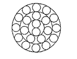
スチ−ルコ−ドのシ−ス(コア以外の外周に巻き付けた全てのシ−スをさす)を構成する隣接する鋼素線間の隙間の平均値d(図14参照)を、0.02(mm)≦d≦素線径x1.5(mm)の範囲としたのは、隣接するシ−ス素線間の隙間の平均値が0.02mm未満ではタイヤ加硫時にコア近傍の内部にまでゴムを侵入させることが難しく、又、素線径x1.5を越える隙間とするとシ−ス素線の配置に乱れを生じて耐疲労性が低下するし、スチ−ルコ−ド外接円断面内の素線の充填率が低くスチ−ルコ−ド強力が不足するかスチ−ルコ−ド径が大きくなり、スチ−ルコ−ド・ゴム複合体の厚さが大きくなりタイヤの軽量化に不利に作用する。
【0018】
スチ−ルコ−ドの撚りを解すと螺旋形状をした複数本の鋼素線が得られるが、これは真直な鋼素線をスチ−ルコ−ドとする撚線工程において鋼素線に塑性変形を与えるためで、これによって伸線工程で鋼素線の表面引張り残留応力を低減しても撚線工程で鋼素線の螺旋内側に最大引張り残留応力が発生してしまい耐腐食疲労性が低下することを見出し、スチ−ルコ−ドとなした鋼素線の螺旋内側の表層引張り残留応力を小さくすればスチ−ルコ−ドの耐腐食疲労性が改善できるという発明に至ったものである。
【0019】
タイヤ補強用スチ−ルコ−ドにおいては、タイヤが車両に装着されて走行する際に繰り返し曲げを受けてスチ−ルコ−ドを構成する鋼素線同士が摩擦摩耗するフレッティングを生じ更に腐食疲労し易くなる。このため、好ましくは鋼素線の表面から素線直径の5%までの深さの範囲で引張り残留応力を小さくするもので、更に好ましくは鋼素線の表面から素線直径の10%深さまでの引張り残留応力を小さくするのが良い。
【0020】
この発明ではスチ−ルコ−ドの最外層に巻き付ける1本のラッピングワイヤを位置させないことにより、シ−ス素線とラッピングワイヤのフレッティングを防止することができるので、タイヤを長期間使用してもスチ−ルコ−ド強力の低下を極めて少なくすることができ、又、スチ−ルコ−ドの直径が小さくなるためにタイヤの軽量化に有利に働くこととなる。
【0021】
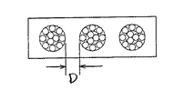
タイヤカ−カスのビ−ド部付近での50mm幅当たりの複合体の強力に対してスチ−ルコ−ド径を、(50xコ−ド強力)/複合体強力−1.1≦コ−ド径(mm)≦(50xコ−ド強力)/複合体強力−0.4としたのは、タイヤのビ−ド部付近のスチ−ルコ−ド間隔D(図13参照)を0.4〜1.1mmの範囲にするためで、この範囲に規定することでカ−カス部の耐久性を向上させることができる。
【0022】
即ち、ほぼ平行に並べられたスチ−ルコ−ド間のゴムの長さが0.4mm未満では、タイヤ走行時にカ−カス部に加わる応力に対してゴムの剪断応力が大きくなり過ぎてスチ−ルコ−ド間のゴムに亀裂が発生し易くなるし、スチ−ルコ−ド・ゴム間の接着破壊も起こり易くなる。一方、1.1mmを越えるとタイヤに空気を充填した際にスチ−ルコ−ド間のゴムの膨れが生じてゴムに加わる負担が大きくなると共に、タイヤ走行時にゴムの発熱が大きくなるために高速耐久性が低下する。
更に好ましくは、タイヤのビ−ド部付近のスチ−ルコ−ドの間隔を0.6乃至0.9mmの範囲にするために、スチ−ルコ−ドの直径dを、[(50xコ−ド強力)/複合体強力]−0.9≦d(mm)≦[(50xコ−ド強力)/複合体強力]−0.6とすることが好ましい。
【0023】
【実施例】
以下、実施例をもって本発明を更に詳細に説明する。
重量%でC:0.81%、Si:0.23%、Mn:0.49%、P:0.006%、S:0.008%の成分を有するプレ−ンカ−ボン鋼で直径が5.5mmのスチ−ルコ−ド線材を乾式伸線して所望の直径とした後、パテンティング処理及びブラスメッキを施して湿式伸線により真歪3.8の真線加工を行い、直径0.21mm、引張強さ3695N/mm2 の鋼素線を製造した。尚、この際、伸線後の鋼素線に張力を与えながら繰り返し曲げを与え、鋼素線表層部の引張り残留応力を低減することが好ましい。
【0024】
撚線はチュ−ブラ−撚線機により通常の方法によってスチ−ルコ−ドとするが、この発明ではスチ−ルコ−ドを矯正ロ−ラ−に通過させる際にスチ−ルコ−ドに張力を与え、例えば3+8x0.21mmのコ−ドでは450N/コ−ドの張力を与えてスチ−ルコ−ドを構成する鋼素線の螺旋内側の引張り残留応力を低減させた。撚線機はチュ−ブラ−型に限定されるものではなくバンチャ−撚線機を用いることもできる。
【0025】
又、上記スチ−ルコ−ドをカ−カスプライに用いたタイヤを試作した。図15は空気入りタイヤの断面図であり、図中、aはベルト、bはカ−カス、cはビ−ドである。タイヤのサイズは11R22.5・14PRであり、カ−カスプライのコ−ド打ち込み数は31.5本/5cmである。
製造したスチ−ルコ−ド及び試作したタイヤの特性を表1、表2、表3にまとめて示す。表1にあって、スチ−ルコ−ドの各構造は、従来例1は図4の構造、比較例1は3+9+15の構造、実施例1〜6は夫々図7〜図12に示す構造のものである。又、表2にあって、スチ−ルコ−ドの各構造は、従来例2は図3の構造、比較例2は3+9の構造、実施例7〜12は夫々図6〜図11に示す構造のものである。更に、表3にあって、スチ−ルコ−ドの各構造は、従来例3は図3の構造、比較例3の構造は図3に示す構造、実施例13〜17は夫々図5〜図9に示す構造のものである。
【0026】
【表1】

【表2】
【表3】
スチ−ルコ−ド間隔はタイヤのビ−ド部付近のカ−カスコ−ド折り返し部にて測定し、又、スチ−ルコ−ド使用重量は従来例を100としてタイヤのカ−カス中に埋設されたスチ−ルコ−ド重量を指数表示しており、数値が小さいほど軽量化の点で優れている。
【0030】
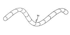
表面から3%深さでの曲率変化は、タイヤ中のカ−カスコ−ド1本を取りスチ−ルコ−ドの撚りを解して螺旋状の型付を有する鋼素線となし、外層を構成する鋼素線について100mm長さに切断し長手方向に向かって半円周にエナメルを塗布し、次いで50%硝酸水溶液に浸漬してエナメルを塗布していない半円周側を線径の3%深さまで溶解しその時の素線の動きを測定した。
測定は図1〜図2に示す通りであり、図中、R0 は螺旋内側の表層部除去前の螺旋曲率半径(mm)であり、R1 は螺旋内側表層部除去後の螺旋曲率半径(mm)である。
従来例1〜3及び比較例1〜3では、螺旋内側の表層部を除去すると引張り残留応力のためにR1 が大きくなり、(R1 /R0 )×100が100を越えたが、実施例1〜17では、スチ−ルコ−ドを矯正ロ−ラ−に通過させる撚りの際に張力を与えて引張り残留応力を低減させたので、螺旋内側の表層部を除去するとR1 が小さくなり、(R1 /R0 )×100が100未満になった。
【0031】
ゴムペネ性はタイヤ中のカ−カスコ−ド1本を取り、スチ−ルコ−ドの全長にわたってコアの表面に被覆しているゴムの度合いを観察し、90〜100%であれば◎、80〜89%であれば○、79%以下をxとして評価した。尚、80%以上であれば実用上問題はない。
【0032】
強力保持率は、各試験タイヤをドラムテストによってJIS正規内圧荷重下のもとで20万Km走行させた後、タイヤからカ−カスコ−ドを採取し、その強力を測定し、試験前のスチ−ルコ−ドに対する割合で示したものである。
【0033】
耐腐食疲労性は、各試験タイヤのリム組み時にタイヤのインナ−ライナ−内側にチュ−ブを配し、インナ−ライナ−とチュ−ブとの間に300m1の水を封入し、各試験タイヤをJIS正規内圧及び正規荷重の条件下でのドラムテストにおけるカ−カスコ−ド切れ(CBU)故障に至るまでの寿命(走行距離)により評価した。尚、従来例の走行距離を100として指数表示しており指数が大きいほど耐腐食疲労性に優れている。
【0034】
【発明の効果】
以上のように、高い引張強さを有する鋼素線からなる2層撚り或いは3層撚りのスチ−ルコ−ドであって、シ−スの鋼素線間に隙間を設けかつ鋼素線の螺旋内側表層部の引張り残留応力を低減し、更にスチ−ルコ−ドにはラッピングワイヤを施していないので繰り返し曲げ後のコ−ド強力保持率が向上し耐腐食疲労性も向上したスチ−ルコ−ドとなった。このスチ−ルコ−ドを使用した車両用タイヤにあっては、その耐久性を向上させ、タイヤの軽量化による車両の燃費性を改善することができるので、資源の節約及び自然環境の保護に極めて有用な車両用空気入りタイヤを提供することができる。
【図面の簡単な説明】
【図1】図1はスチ−ルコ−ドの撚りを解した鋼素線の螺旋を示し、この撚りを解した状態図である。
【図2】図2はスチ−ルコ−ドの撚りを解した鋼素線の螺旋を示し、この撚りを解し螺旋内側表層部を溶解した後の状態図である。
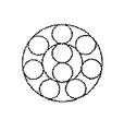
【図3】図3は従来の3+9+1構造のスチ−ルコ−ドの断面図である。
【図4】図4は従来の3+9+15+1構造のスチ−ルコ−ドの断面図である。
【図5】図5は本発明の1+5構造のスチ−ルコ−ドの断面図である。
【図6】図6は本発明の2+7構造のスチ−ルコ−ドの断面図である。
【図7】図7は本発明の3+8構造のスチ−ルコ−ドの断面図である。
【図8】図8は本発明の4+9構造のスチ−ルコ−ドの断面図である。
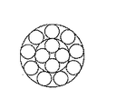
【図9】図9は本発明の1+5+10構造のスチ−ルコ−ドの断面図である。
【図10】図10は本発明の2+7+12構造のスチ−ルコ−ドの断面図である。
【図11】図11は本発明の3+8+13構造のスチ−ルコ−ドの断面図である。
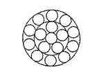
【図12】図12は本発明の4+9+14構造のスチ−ルコ−ドの断面図である。
【図13】図13はスチ−ルコ−ド間隔を示す断面図である。
【図14】図14はシ−ス素線間の隙間を示す断面図である。
【図15】図15は空気入りタイヤの断面図である。[0001]
BACKGROUND OF THE INVENTION
The present invention relates to a steel cord for tire reinforcement and a pneumatic tire using the same, and more particularly, a steel cord which is used for reinforcing a carcass portion of a tire and which has improved weight and durability. And pneumatic tires for large vehicles.
[0002]
[Prior art]
In recent years, from the viewpoint of protecting the global environment, the goal has been to reduce the fuel consumption of vehicles, and the weight of tires has also been reduced. In steel cords, which are tire reinforcements, the strength is increased to maintain tire reinforcement. However, attempts have been made to reduce the amount used. However, on the other hand, it is widely known that fatigue resistance decreases when the tensile strength per unit cross-sectional area of the steel wire constituting the steel cord is increased.
[0003]
For this reason, high strength and high ductility small diameter steel wires are manufactured by increasing the number of wire drawing dies in wet continuous wire drawing, and reducing the area reduction rate of each die to suppress heat generation during wire drawing. A method is proposed in Japanese Patent Laid-Open No. 3-104821. Further, by using a steel cord made of carbon steel having a carbon content of 0.90 to 0.95 wt% and a chromium content of 0.10 to 0.40 wt% as a raw material, Japanese Laid-Open Patent Publication No. 4-126605 proposes a technique for reducing the weight while maintaining the durability of the tire. However, in order to reduce the weight of the tire, it can be achieved by reducing the amount of the member to be used. However, it is undeniable that the strength may be lowered and the durability may be lowered accordingly.
[0004]
In the conventional technique described above, the method of drawing by increasing the number of drawing dies has a problem that the drawing workability is deteriorated, while the carbon steel component used as the raw material of the steel cord is specially selected. If so, it becomes an expensive steel code and is not practical.
[0005]
[Problems to be solved by the invention]
Conventionally, the carcass part of a pneumatic tire for trucks and buses has a 3 + 9 × 0.23 + 1 two-layer twist structure with steel strands having a tensile strength of about 2750 to 3150 N / mm 2 , or a 3 + 9 + 15 × 0.175 + 1 three layer A steel cord having a twisted structure is mainly used. However, if a 3 + 9 × 0.21 structure in which the diameter of the steel cord is reduced in order to reduce the weight of the tire, the steel cord is used to secure the tire strength. There is a problem that it is necessary to increase the number of driven-in cards, and as a result, the adjacent distance between the steel cords of the carcass becomes too narrow and the failure of the carcass ply turn-up ends increases.
[0006]
Further, since the steel cords of the 3 + 9 + 1 structure described above are in close contact with each other, the steel wire is moved by relative movement between the steel strands constituting the steel cord by rolling of the tire. The strands wear and the strength of the steel cord decreases. Furthermore, if the wrapping wire surrounds the outer periphery of the steel cord, the tendency of the steel cord to decrease in strength increases.
[0007]
In some cases, tires are sometimes damaged by the protrusions on the road surface or the protrusions on the side walls, reaching the vicinity of the steel cord. It may reduce the sex. For this, a method of reducing the corrosion of the steel wire by reducing the number of steel wires constituting the outer layer and providing a gap between the wires so that the rubber can enter the steel cord. However, there is a problem that a satisfactory effect cannot be obtained unless the rubber is sufficiently infiltrated into the gap. Further, even if the rubber penetrates sufficiently, there is a problem that the corrosion fatigue resistance of the steel wire is not always sufficient due to moisture contained in the rubber.
[0008]
[Means for Solving the Problems]
The first steel reinforcing steel cord of the present invention has a carbon content of 0.70% by weight or more, a diameter of 0.15 to 0.25 mm, and a tensile strength of 3400 to 3900 N / mm 2 . M + N structure in which the number M of steel strands constituting the core is 1-4 and the number N of steel strands constituting the sheath surrounding the core is M + (2-5) Two layers twisted steel cord or three layers of M + N + P structure in which P steel strands are further wound around the outer periphery of the above two layer twisted steel cord and P is N + (2-5) It is a twisted steel cord, and the average value of the gaps between adjacent steel strands constituting the sheath is 0.02 mm or more and 1.5 times or less of the steel strand diameter, constituting the sheath By setting the die forming rate of the steel wire to be 80 to 110%, the wrapping wire is not positioned on the outer periphery of the sheath. The steel cord is untwisted by reducing the tensile residual stress inside the helix of the steel wire constituting the steel cord by applying tension to the steel cord during twisting. The ratio of the spiral radius of curvature R 0 of the steel wire having a spiral type obtained in this way to the radius of curvature R 1 of the spiral when the surface layer in the inner part of the spiral of the steel strand is dissolved and removed (R 1 / R 0 ) × 100 is set to be less than 100, and a steel cord for reinforcing tires is provided.
[0009]
Preferably, the surface layer ranges from the surface of the steel strand to a depth from the surface corresponding to 5% of the diameter of the steel strand, and particularly preferably, the surface layer extends from the surface of the steel strand to the steel strand. This relates to a steel cord for reinforcing tires in a range from the surface to a depth corresponding to 10% of the diameter of the tire. The carbon content of the steel wire is preferably 0.7 to 0.85% by weight.
[0010]
A steel cord for reinforcing a tire according to the present invention, wherein the diameter d of the steel cord is a composite per 50 mm width of a rubberized steel cord / rubber composite before being molded into a tire. Preferably, the strength is in the range of (50 × code strength) / composite strength−1.1 ≦ d (mm) ≦ (50 × code strength) / composite strength−0.4. , (50 × code strength) / composite strength−0.9 ≦ d (mm) ≦ (50 × code strength) / composite strength−0.6 And a steel code in which the number of steel wires constituting the steel code is selected.
[0011]
In the pneumatic tire according to the second aspect of the present invention, as the reinforcing material, the carbon content is 0.70% by weight or more, the diameter is 0.15 to 0.25 mm, and the tensile strength is 3400 to 3900 N / mm. the steel wire in a second range, the steel element wires count M is 1 to 4 pieces of constituting the core, sheet surrounding the core - the number N of the steel element wires constituting the scan is M + (2 to 5) books and 2-layer stranded steel cord of M + N structure or M + N + P structure in which P steel strands are further wound around the outer periphery of the above-mentioned 2-layer stranded steel cord, and P is N + (2-5) A three-layer stranded steel cord, wherein the average value of the gaps between adjacent steel strands constituting the sheath is 0.02 mm or more and 1.5 times or less of the steel strand diameter, The wrapping wire is attached to the outer periphery of the sheath by setting the die forming rate of the steel wire constituting the sheath to 80 to 110%. The steel cord is twisted by reducing the tensile residual stress inside the helix of the steel wire constituting the steel cord by applying tension to the steel cord during twisting. The ratio of the spiral radius of curvature R 0 of the steel wire having a spiral shape obtained by solving the above and the radius of curvature R 1 of the spiral when the surface layer in the spiral inner portion of the steel strand is dissolved and removed, The present invention relates to a pneumatic tire using a steel cord in which (R 1 / R 0 ) × 100 is less than 100. In particular, the pneumatic tire is used to reinforce a carcass portion of the pneumatic tire.
[0012]
Regarding the structure of the steel cord used, the surface layer ranges from the surface of the steel wire to a depth from the surface corresponding to 5%, preferably 10% of the diameter of the steel wire. The present invention relates to a pneumatic tire using a cord. .
Further, a steel cord having a carbon content of 0.7 to 0.85% by weight is used.
[0013]
Further, regarding the structure of the steel cord, the composite strength per 50 mm width of the rubberized steel cord / rubber composite before the diameter d is formed on the tire is 50x cord. Strength) / composite strength−1.1 ≦ d (mm) ≦ (50 × code strength) / composite strength−0.4, preferably (50 × code strength) / Composite strength-0.9 ≤ d (mm) ≤ (50x code strength) / Composite strength-0.6 The steel wire diameter and steel code are configured in the range of The steel cord with the number of steel strands to be selected is used.
[0014]
DETAILED DESCRIPTION OF THE INVENTION
Hereinafter, embodiments of the present invention will be described in more detail with a steel cord for reinforcing tires. The reason why the carbon content of the carbon steel used as the raw material for the steel cord is limited to 0.70% by weight or more is to make the tensile strength of the steel strand 3400-3900 N / mm 2 , preferably By setting the carbon content to 0.85% by weight or less, it becomes easy to suppress the formation of the initial cementite during patenting and ensure the ductility of the steel wire. The carbon steel used in the present invention is preferably plane carbon in order to suppress an increase in price.
[0015]
Moreover, the reason for limiting the diameter of the steel wire to 0.15 to 0.25 mm is that if it is less than 0.15 mm, the tensile strength of the steel wire increases, but the productivity in wire drawing decreases, which is economical. However, if it exceeds 0.25 mm, the bending fatigue resistance deteriorates repeatedly, and the bending rigidity of the steel cord becomes too large, so that the workability at the time of molding the tire, particularly the bead portion, becomes difficult.
Further, the steel wire is limited in tensile strength if it is less than 3400 N / mm 2 , it is difficult to maintain the steel cord strength, and the tire strength cannot be maintained and the weight cannot be reduced. Further, if the tensile strength of the steel wire exceeds 3900 N / mm 2 , the wire drawing productivity may be lowered, or the ductility of the obtained steel wire may be poor, and there is a concern that the number of tire regenerations may be reduced. .
[0016]
The diameters of the core and sheath steel strands used in this invention need not be the same, but productivity can be improved by making them the same.
The steel cord structure has two layers in which the number M of steel wires constituting the core is 1 to 4, and the number N of steel wires constituting the sheath is M + (2 to 5). The twisted steel cord or the three-layer twisted steel cord in which N + (2-5) steel strands are arranged on the outer periphery of the two-layer twisted steel cord is used for the penetration of rubber. Steel cord diameter to make the twisted form not to be disadvantageous for fatigue resistance while satisfying the properties, to improve the wire filling rate in the steel cord cross section and to reduce the required code strength as much as possible It is for trying to get in. Therefore, the number of steel wires constituting the core is preferably one or two having no space inside, or three having a small inner space.
[0017]
An average value d (see FIG. 14) of gaps between adjacent steel wires constituting a steel cord case (referring to all the sheaths wound around the outer periphery other than the core) is 0.02. The range of (mm) ≦ d ≦ element diameter x1.5 (mm) is that if the average value of the gap between adjacent sheath elements is less than 0.02 mm, it will be inside the vicinity of the core during tire vulcanization. It is difficult to infiltrate the rubber, and if the gap exceeds the wire diameter x1.5, the arrangement of the sheath wire will be disturbed and the fatigue resistance will be reduced. The filling rate of the inner wire is low and the strength of the steel cord is insufficient or the diameter of the steel cord is increased, and the thickness of the steel cord / rubber composite is increased, which is disadvantageous in reducing the weight of the tire. Act on.
[0018]
When the steel cord is untwisted, a plurality of helically shaped steel strands are obtained. This is a plastic deformation of the steel strands in the stranding process in which straight steel strands are used as steel cords. Therefore, even if the surface tensile residual stress of the steel wire is reduced in the wire drawing process, the maximum tensile residual stress is generated inside the spiral of the steel wire in the twisting process, resulting in a decrease in corrosion fatigue resistance. As a result, the present invention has led to the invention that the corrosion fatigue resistance of the steel cord can be improved by reducing the surface tensile residual stress inside the spiral of the steel wire formed into the steel cord.
[0019]
In the steel cord for tire reinforcement, when the tire is mounted on a vehicle and traveling, it is repeatedly bent to cause fretting in which the steel wires constituting the steel cord are frictionally worn, and further corrosion fatigue occurs. It becomes easy to do. For this reason, it is preferable to reduce the tensile residual stress in a depth range from the surface of the steel strand to 5% of the strand diameter, and more preferably from the surface of the steel strand to a depth of 10% of the strand diameter. It is better to reduce the tensile residual stress.
[0020]
In this invention, since the single wrapping wire wound around the outermost layer of the steel cord is not positioned, fretting of the sheath wire and the wrapping wire can be prevented. However, the decrease in steel cord strength can be extremely reduced, and the diameter of the steel cord is reduced, which is advantageous in reducing the weight of the tire.
[0021]
Steel cord diameter with respect to the composite strength per 50 mm width in the vicinity of the bead portion of the tire carcass, (50 × code strength) / composite strength−1.1 ≦ code diameter (Mm) ≦ (50 × code strength) / composite strength−0.4 means that the steel cord interval D (see FIG. 13) near the bead portion of the tire is 0.4 to 1. In order to make it into the range of 1 mm, the durability of the carcass part can be improved by defining in this range.
[0022]
That is, if the length of the rubber between the steel cords arranged substantially in parallel is less than 0.4 mm, the shear stress of the rubber becomes too large with respect to the stress applied to the carcass portion during running of the tire. Cracks are likely to occur in the rubber between the cords, and adhesion failure between the steel cord and the rubber is also likely to occur. On the other hand, if it exceeds 1.1 mm, when the tire is filled with air, the rubber between the steel cords swells, increasing the burden on the rubber and increasing the heat generated by the rubber when the tire is running. Durability decreases.
More preferably, in order to make the distance between the steel cords near the tire bead portion in the range of 0.6 to 0.9 mm, the diameter d of the steel cord is set to [(50x code Strength) / Composite strength] −0.9 ≦ d (mm) ≦ [(50 × code strength) / Composite strength] −0.6.
[0023]
【Example】
Hereinafter, the present invention will be described in more detail with reference to examples.
Plane carbon steel with the components of C: 0.81% by weight, Si: 0.23%, Mn: 0.49%, P: 0.006%, S: 0.008% A 5.5 mm steel cord wire is dry-drawn to a desired diameter, and then subjected to a patenting treatment and brass plating, and a true wire is processed with a true strain of 3.8 by wet drawing. A steel strand having a tensile strength of 3695 N / mm 2 was produced. At this time, it is preferable to repeatedly bend the steel wire after drawing while applying tension to reduce the tensile residual stress in the surface layer portion of the steel wire.
[0024]
The stranded wire is made into a steel cord by a conventional method using a twister. However, in the present invention, the steel cord is tensioned when passing through the straightening roller. For example, in the case of a code of 3 + 8 × 0.21 mm, a tension of 450 N / code was applied to reduce the tensile residual stress inside the helix of the steel wire constituting the steel cord. The twisting machine is not limited to the tuber type, and a buncher-twisting machine can also be used.
[0025]
In addition, a tire using the steel cord as a carcass ply was made as a trial. FIG. 15 is a cross-sectional view of a pneumatic tire, in which a is a belt, b is a carcass, and c is a bead. The size of the tire is 11R22.5 · 14PR, and the number of code driving of the carcass ply is 31.5 / 5cm.
Tables 1, 2 and 3 collectively show the characteristics of the manufactured steel cords and the prototype tires. In Table 1, each structure of the steel cord is the structure shown in FIG. 4 for the conventional example 1, the structure 3 + 9 + 15 for the comparative example 1, and the structures shown in FIGS. 7 to 12 for the examples 1 to 6, respectively. It is. Further, in Table 2, the structure of the steel code is as shown in FIG. 3 for the conventional example 2, the structure 3 + 9 for the comparative example 2, and the structures shown in FIGS. 6 to 11 for the examples 7 to 12, respectively. belongs to. Further, in Table 3, the structure of the steel code is the structure shown in FIG. 3 for the conventional example 3, the structure shown in FIG. 3 for the comparative example 3, and the structures shown in FIGS. 9 has the structure shown in FIG.
[0026]
[Table 1]
[Table 2]
[Table 3]
The steel code interval was measured at the carcass folded portion near the tire bead, and the steel code used weight was embedded in the tire carcass as a conventional example of 100. The steel code weight is displayed as an index, and the smaller the value, the better the weight reduction.
[0030]
The change in curvature at a depth of 3% from the surface is obtained by taking one carcass cord in the tire and untwisting the steel cord to form a steel wire having a spiral type, and forming an outer layer. The steel wire constituting the steel wire is cut to a length of 100 mm, enamel is applied to the semicircular direction in the longitudinal direction, and then immersed in a 50% nitric acid aqueous solution, the semicircular side where the enamel is not applied is set to 3 % Movement to the depth was measured.
The measurement is as shown in FIGS. 1 and 2, in which R 0 is the radius of curvature of the spiral (mm) before removing the surface layer inside the spiral, and R 1 is the radius of curvature of the spiral after removing the surface layer inside the spiral ( mm).
In Conventional Examples 1 to 3 and Comparative Examples 1 to 3, when the surface layer inside the helix was removed, R 1 increased due to the tensile residual stress, and (R 1 / R 0 ) × 100 exceeded 100. In Examples 1 to 17, since the tensile residual stress was reduced by applying a tension when the steel cord was passed through the straightening roller, R 1 was reduced by removing the surface layer inside the helix. , (R 1 / R 0 ) × 100 was less than 100.
[0031]
For rubber penetrability, take one carcass cord in the tire and observe the degree of rubber covering the surface of the core over the entire length of the steel cord. If it was 89%, it was evaluated as ○, and 79% or less as x. If it is 80% or more, there is no practical problem.
[0032]
The strength retention is determined by running each test tire under a JIS regular internal pressure load by running a drum test for 200,000 km, then collecting the carcass code from the tire, measuring its strength, and -Expressed as a percentage of the code.
[0033]
Corrosion fatigue resistance is determined by placing a tube inside the inner liner of the tire when assembling the rim of each test tire, and enclosing 300 ml of water between the inner liner and the tube. Was evaluated by the life (travel distance) until the carcass cord breakage (CBU) failure in the drum test under the conditions of JIS normal internal pressure and normal load. In addition, the distance of the conventional example is shown as an index, and the larger the index, the better the corrosion fatigue resistance.
[0034]
【The invention's effect】
As described above, the steel cord is a two-layer stranded or three-layer stranded steel cord having a high tensile strength, and a gap is provided between the steel strands of the sheath. Steel cord with reduced tensile residual stress on the inner surface layer of the spiral and with no wrapping wire applied to the steel cord, improving the strength retention of the cord after repeated bending and improving corrosion fatigue resistance -It became de. In the vehicle tire using this steel cord, its durability can be improved and the fuel efficiency of the vehicle can be improved by reducing the weight of the tire, so that it can save resources and protect the natural environment. A very useful pneumatic tire for a vehicle can be provided.
[Brief description of the drawings]
BRIEF DESCRIPTION OF DRAWINGS FIG. 1 shows a steel wire helix with a steel cord untwisted and a state diagram with the twist unwound.
FIG. 2 is a state diagram after showing the helix of the steel wire with the steel cord untwisted and after untwisting and melting the inner surface layer portion of the helix.
FIG. 3 is a cross-sectional view of a conventional steel code having a 3 + 9 + 1 structure.
FIG. 4 is a cross-sectional view of a conventional steel code having a 3 + 9 + 15 + 1 structure.
FIG. 5 is a cross-sectional view of a steel cord having a 1 + 5 structure according to the present invention.
FIG. 6 is a cross-sectional view of a steel cord having a 2 + 7 structure according to the present invention.
FIG. 7 is a cross-sectional view of a 3 + 8 structure steel cord of the present invention.
FIG. 8 is a cross-sectional view of a steel cord having a 4 + 9 structure according to the present invention.
FIG. 9 is a cross-sectional view of a steel code having a 1 + 5 + 10 structure according to the present invention.
FIG. 10 is a cross-sectional view of a steel code of 2 + 7 + 12 structure according to the present invention.
FIG. 11 is a cross-sectional view of a steel cord of 3 + 8 + 13 structure according to the present invention.
FIG. 12 is a sectional view of a steel code having a 4 + 9 + 14 structure according to the present invention.
FIG. 13 is a cross-sectional view showing a steel code interval.
FIG. 14 is a cross-sectional view showing a gap between sheath strands.
FIG. 15 is a cross-sectional view of a pneumatic tire.
Claims (13)
Priority Applications (8)
| Application Number | Priority Date | Filing Date | Title |
|---|---|---|---|
| JP32400695A JP3606972B2 (en) | 1995-11-17 | 1995-11-17 | Steel cord for reinforcing tire and pneumatic tire using the same |
| US08/652,082 US5806296A (en) | 1995-05-26 | 1996-05-23 | Corrosion resistant spiral steel filament and steel cord made therefrom |
| ES96303709T ES2202415T3 (en) | 1995-05-26 | 1996-05-24 | STEEL THREADS AND PNEUMATIC COVER FOR USE. |
| EP96303709A EP0744490B1 (en) | 1995-05-26 | 1996-05-24 | Steel cord and pneumatic tire using the same |
| DE69629076T DE69629076T2 (en) | 1995-05-26 | 1996-05-24 | Steel cable and thus reinforced pneumatic tire |
| KR1019960017923A KR100431373B1 (en) | 1995-05-26 | 1996-05-25 | Steel cord and pneumatic tire using the same |
| US08/769,572 US5873962A (en) | 1995-05-26 | 1996-12-19 | Tire having corrosion resistant steel cord |
| US08/944,223 US5822973A (en) | 1995-05-26 | 1997-10-06 | Corrosion resistant steel filament |
Applications Claiming Priority (1)
| Application Number | Priority Date | Filing Date | Title |
|---|---|---|---|
| JP32400695A JP3606972B2 (en) | 1995-11-17 | 1995-11-17 | Steel cord for reinforcing tire and pneumatic tire using the same |
Publications (2)
| Publication Number | Publication Date |
|---|---|
| JPH09143890A JPH09143890A (en) | 1997-06-03 |
| JP3606972B2 true JP3606972B2 (en) | 2005-01-05 |
Family
ID=18161083
Family Applications (1)
| Application Number | Title | Priority Date | Filing Date |
|---|---|---|---|
| JP32400695A Expired - Fee Related JP3606972B2 (en) | 1995-05-26 | 1995-11-17 | Steel cord for reinforcing tire and pneumatic tire using the same |
Country Status (1)
| Country | Link |
|---|---|
| JP (1) | JP3606972B2 (en) |
Families Citing this family (16)
| Publication number | Priority date | Publication date | Assignee | Title |
|---|---|---|---|---|
| JP2006274527A (en) * | 2005-03-04 | 2006-10-12 | Bridgestone Corp | Steel cord for rubber reinforcement and pneumatic radial tire produced by using the same |
| JP4806587B2 (en) * | 2006-05-25 | 2011-11-02 | 東京製綱株式会社 | Steel cord manufacturing method and steel cord |
| JP5070804B2 (en) * | 2006-10-30 | 2012-11-14 | 横浜ゴム株式会社 | Pneumatic tire |
| JP2008290657A (en) * | 2007-05-28 | 2008-12-04 | Toyo Tire & Rubber Co Ltd | Pneumatic radial tire |
| FR2947577B1 (en) * | 2009-07-03 | 2013-02-22 | Michelin Soc Tech | METAL CABLE WITH THREE LAYERS GUM IN SITU CONSTRUCTION 3 + M + N |
| FR2947576B1 (en) * | 2009-07-03 | 2011-08-19 | Michelin Soc Tech | METAL CABLE WITH THREE LAYERS GUM IN SITU CONSTRUCTION 2 + M + N |
| KR101106367B1 (en) * | 2009-12-22 | 2012-01-18 | 한국타이어 주식회사 | Tire reinforcing steel cord with excellent rubber penetration and pneumatic radial tires comprising the same |
| FR2962454B1 (en) * | 2010-05-20 | 2012-09-21 | Michelin Soc Tech | PROCESS FOR MANUFACTURING A THREE-LAYER METAL CABLE OF THE TYPE IN SITU GUM |
| JP5937395B2 (en) * | 2012-03-23 | 2016-06-22 | 株式会社ブリヂストン | Pneumatic radial tire |
| FR3020017B1 (en) | 2014-04-22 | 2017-06-09 | Michelin & Cie | PNEUMATIC VEHICLE FOR CIVIL ENGINEERING |
| FR3020016B1 (en) | 2014-04-22 | 2016-04-01 | Michelin & Cie | PNEUMATIC FOR HEAVY INDUSTRIAL VEHICLE |
| CN105648810A (en) * | 2014-06-18 | 2016-06-08 | 贝卡尔特公司 | Steel cord for reinforcing pneumatic tire |
| WO2016129595A1 (en) * | 2015-02-13 | 2016-08-18 | 株式会社ブリヂストン | Rubber article reinforcing steel cord and pneumatic tire using same |
| JP6717701B2 (en) | 2016-08-05 | 2020-07-01 | 株式会社ブリヂストン | Steel cord for tire and pneumatic tire using the same |
| JP6930187B2 (en) * | 2017-04-10 | 2021-09-01 | 横浜ゴム株式会社 | Pneumatic radial tire |
| FR3103201A1 (en) * | 2019-11-15 | 2021-05-21 | Compagnie Generale Des Etablissements Michelin | Two-layer multi-strand cable with improved performance sheathed inner layer |
-
1995
- 1995-11-17 JP JP32400695A patent/JP3606972B2/en not_active Expired - Fee Related
Also Published As
| Publication number | Publication date |
|---|---|
| JPH09143890A (en) | 1997-06-03 |
Similar Documents
| Publication | Publication Date | Title |
|---|---|---|
| KR100431373B1 (en) | Steel cord and pneumatic tire using the same | |
| JP3643123B2 (en) | Steel cord for reinforcing rubber articles and pneumatic tire | |
| JP3606972B2 (en) | Steel cord for reinforcing tire and pneumatic tire using the same | |
| KR960006935B1 (en) | Heavy-load radial tire | |
| JP3455352B2 (en) | Steel cord for rubber reinforcement and radial tire using the same | |
| US8720175B2 (en) | Crimped flat wire as core of oval cord | |
| CN105297502B (en) | Heavy duty tire band beam portion's steel cord for reinforcing and Pneumatic tire for heavy load | |
| JPWO1997039176A1 (en) | Steel cord for reinforcing rubber parts and pneumatic tires | |
| JPH1181168A (en) | Steel code for rubber article and pneumatic radial tire | |
| JP3759292B2 (en) | Steel cord for reinforcing rubber articles and pneumatic tire | |
| JP3179915B2 (en) | Pneumatic tire | |
| JP4050827B2 (en) | Steel cord for rubber article reinforcement | |
| JP4633517B2 (en) | Steel cord and tire | |
| JP3887789B2 (en) | Steel cord for tire reinforcement | |
| JP3093390B2 (en) | Steel cord for reinforcing rubber articles and method for producing the same | |
| JP2637516B2 (en) | Pneumatic radial tire | |
| JP3678871B2 (en) | Steel cord for rubber reinforcement and radial tire for heavy loads using the same | |
| JP2895689B2 (en) | Steel cord for reinforcing rubber articles and method for producing the same | |
| JPH04308287A (en) | Steel cord for reinforcing rubber article | |
| JP3411621B2 (en) | Pneumatic radial tire for heavy loads | |
| JP3497935B2 (en) | Steel cord for reinforcing rubber articles and pneumatic radial tire | |
| JP4848944B2 (en) | Steel cord for rubber reinforcement and pneumatic radial tire using the same | |
| JPH11314503A (en) | Radial tire | |
| JP2000256976A (en) | Steel cord for reinforcing tire | |
| JP4904951B2 (en) | Steel cord for rubber reinforcement and pneumatic radial tire using the same |
Legal Events
| Date | Code | Title | Description |
|---|---|---|---|
| TRDD | Decision of grant or rejection written | ||
| A01 | Written decision to grant a patent or to grant a registration (utility model) |
Free format text: JAPANESE INTERMEDIATE CODE: A01 Effective date: 20041005 |
|
| A61 | First payment of annual fees (during grant procedure) |
Free format text: JAPANESE INTERMEDIATE CODE: A61 Effective date: 20041006 |
|
| R150 | Certificate of patent or registration of utility model |
Free format text: JAPANESE INTERMEDIATE CODE: R150 |
|
| FPAY | Renewal fee payment (event date is renewal date of database) |
Free format text: PAYMENT UNTIL: 20071015 Year of fee payment: 3 |
|
| FPAY | Renewal fee payment (event date is renewal date of database) |
Free format text: PAYMENT UNTIL: 20081015 Year of fee payment: 4 |
|
| FPAY | Renewal fee payment (event date is renewal date of database) |
Free format text: PAYMENT UNTIL: 20091015 Year of fee payment: 5 |
|
| FPAY | Renewal fee payment (event date is renewal date of database) |
Free format text: PAYMENT UNTIL: 20101015 Year of fee payment: 6 |
|
| FPAY | Renewal fee payment (event date is renewal date of database) |
Free format text: PAYMENT UNTIL: 20111015 Year of fee payment: 7 |
|
| FPAY | Renewal fee payment (event date is renewal date of database) |
Free format text: PAYMENT UNTIL: 20121015 Year of fee payment: 8 |
|
| FPAY | Renewal fee payment (event date is renewal date of database) |
Free format text: PAYMENT UNTIL: 20121015 Year of fee payment: 8 |
|
| FPAY | Renewal fee payment (event date is renewal date of database) |
Free format text: PAYMENT UNTIL: 20131015 Year of fee payment: 9 |
|
| R250 | Receipt of annual fees |
Free format text: JAPANESE INTERMEDIATE CODE: R250 |
|
| R250 | Receipt of annual fees |
Free format text: JAPANESE INTERMEDIATE CODE: R250 |
|
| LAPS | Cancellation because of no payment of annual fees |