KR20120046292A - Secondary cell and secondary cell production device - Google Patents
Secondary cell and secondary cell production device Download PDFInfo
- Publication number
- KR20120046292A KR20120046292A KR1020127004923A KR20127004923A KR20120046292A KR 20120046292 A KR20120046292 A KR 20120046292A KR 1020127004923 A KR1020127004923 A KR 1020127004923A KR 20127004923 A KR20127004923 A KR 20127004923A KR 20120046292 A KR20120046292 A KR 20120046292A
- Authority
- KR
- South Korea
- Prior art keywords
- electrode plate
- negative electrode
- positive electrode
- plate
- tab
- Prior art date
- Legal status (The legal status is an assumption and is not a legal conclusion. Google has not performed a legal analysis and makes no representation as to the accuracy of the status listed.)
- Granted
Links
Images








Classifications
-
- H—ELECTRICITY
- H01—ELECTRIC ELEMENTS
- H01M—PROCESSES OR MEANS, e.g. BATTERIES, FOR THE DIRECT CONVERSION OF CHEMICAL ENERGY INTO ELECTRICAL ENERGY
- H01M50/00—Constructional details or processes of manufacture of the non-active parts of electrochemical cells other than fuel cells, e.g. hybrid cells
- H01M50/50—Current conducting connections for cells or batteries
- H01M50/531—Electrode connections inside a battery casing
- H01M50/54—Connection of several leads or tabs of plate-like electrode stacks, e.g. electrode pole straps or bridges
-
- H—ELECTRICITY
- H01—ELECTRIC ELEMENTS
- H01M—PROCESSES OR MEANS, e.g. BATTERIES, FOR THE DIRECT CONVERSION OF CHEMICAL ENERGY INTO ELECTRICAL ENERGY
- H01M10/00—Secondary cells; Manufacture thereof
- H01M10/04—Construction or manufacture in general
- H01M10/0404—Machines for assembling batteries
-
- H—ELECTRICITY
- H01—ELECTRIC ELEMENTS
- H01M—PROCESSES OR MEANS, e.g. BATTERIES, FOR THE DIRECT CONVERSION OF CHEMICAL ENERGY INTO ELECTRICAL ENERGY
- H01M10/00—Secondary cells; Manufacture thereof
- H01M10/04—Construction or manufacture in general
- H01M10/0413—Large-sized flat cells or batteries for motive or stationary systems with plate-like electrodes
-
- H—ELECTRICITY
- H01—ELECTRIC ELEMENTS
- H01M—PROCESSES OR MEANS, e.g. BATTERIES, FOR THE DIRECT CONVERSION OF CHEMICAL ENERGY INTO ELECTRICAL ENERGY
- H01M10/00—Secondary cells; Manufacture thereof
- H01M10/04—Construction or manufacture in general
- H01M10/0468—Compression means for stacks of electrodes and separators
-
- H—ELECTRICITY
- H01—ELECTRIC ELEMENTS
- H01M—PROCESSES OR MEANS, e.g. BATTERIES, FOR THE DIRECT CONVERSION OF CHEMICAL ENERGY INTO ELECTRICAL ENERGY
- H01M10/00—Secondary cells; Manufacture thereof
- H01M10/04—Construction or manufacture in general
- H01M10/049—Processes for forming or storing electrodes in the battery container
-
- H—ELECTRICITY
- H01—ELECTRIC ELEMENTS
- H01M—PROCESSES OR MEANS, e.g. BATTERIES, FOR THE DIRECT CONVERSION OF CHEMICAL ENERGY INTO ELECTRICAL ENERGY
- H01M10/00—Secondary cells; Manufacture thereof
- H01M10/05—Accumulators with non-aqueous electrolyte
- H01M10/052—Li-accumulators
-
- H—ELECTRICITY
- H01—ELECTRIC ELEMENTS
- H01M—PROCESSES OR MEANS, e.g. BATTERIES, FOR THE DIRECT CONVERSION OF CHEMICAL ENERGY INTO ELECTRICAL ENERGY
- H01M50/00—Constructional details or processes of manufacture of the non-active parts of electrochemical cells other than fuel cells, e.g. hybrid cells
- H01M50/10—Primary casings; Jackets or wrappings
- H01M50/102—Primary casings; Jackets or wrappings characterised by their shape or physical structure
- H01M50/103—Primary casings; Jackets or wrappings characterised by their shape or physical structure prismatic or rectangular
-
- H—ELECTRICITY
- H01—ELECTRIC ELEMENTS
- H01M—PROCESSES OR MEANS, e.g. BATTERIES, FOR THE DIRECT CONVERSION OF CHEMICAL ENERGY INTO ELECTRICAL ENERGY
- H01M50/00—Constructional details or processes of manufacture of the non-active parts of electrochemical cells other than fuel cells, e.g. hybrid cells
- H01M50/10—Primary casings; Jackets or wrappings
- H01M50/147—Lids or covers
- H01M50/166—Lids or covers characterised by the methods of assembling casings with lids
-
- H—ELECTRICITY
- H01—ELECTRIC ELEMENTS
- H01M—PROCESSES OR MEANS, e.g. BATTERIES, FOR THE DIRECT CONVERSION OF CHEMICAL ENERGY INTO ELECTRICAL ENERGY
- H01M50/00—Constructional details or processes of manufacture of the non-active parts of electrochemical cells other than fuel cells, e.g. hybrid cells
- H01M50/50—Current conducting connections for cells or batteries
- H01M50/528—Fixed electrical connections, i.e. not intended for disconnection
-
- Y—GENERAL TAGGING OF NEW TECHNOLOGICAL DEVELOPMENTS; GENERAL TAGGING OF CROSS-SECTIONAL TECHNOLOGIES SPANNING OVER SEVERAL SECTIONS OF THE IPC; TECHNICAL SUBJECTS COVERED BY FORMER USPC CROSS-REFERENCE ART COLLECTIONS [XRACs] AND DIGESTS
- Y02—TECHNOLOGIES OR APPLICATIONS FOR MITIGATION OR ADAPTATION AGAINST CLIMATE CHANGE
- Y02E—REDUCTION OF GREENHOUSE GAS [GHG] EMISSIONS, RELATED TO ENERGY GENERATION, TRANSMISSION OR DISTRIBUTION
- Y02E60/00—Enabling technologies; Technologies with a potential or indirect contribution to GHG emissions mitigation
- Y02E60/10—Energy storage using batteries
-
- Y—GENERAL TAGGING OF NEW TECHNOLOGICAL DEVELOPMENTS; GENERAL TAGGING OF CROSS-SECTIONAL TECHNOLOGIES SPANNING OVER SEVERAL SECTIONS OF THE IPC; TECHNICAL SUBJECTS COVERED BY FORMER USPC CROSS-REFERENCE ART COLLECTIONS [XRACs] AND DIGESTS
- Y02—TECHNOLOGIES OR APPLICATIONS FOR MITIGATION OR ADAPTATION AGAINST CLIMATE CHANGE
- Y02P—CLIMATE CHANGE MITIGATION TECHNOLOGIES IN THE PRODUCTION OR PROCESSING OF GOODS
- Y02P70/00—Climate change mitigation technologies in the production process for final industrial or consumer products
- Y02P70/50—Manufacturing or production processes characterised by the final manufactured product
-
- Y—GENERAL TAGGING OF NEW TECHNOLOGICAL DEVELOPMENTS; GENERAL TAGGING OF CROSS-SECTIONAL TECHNOLOGIES SPANNING OVER SEVERAL SECTIONS OF THE IPC; TECHNICAL SUBJECTS COVERED BY FORMER USPC CROSS-REFERENCE ART COLLECTIONS [XRACs] AND DIGESTS
- Y10—TECHNICAL SUBJECTS COVERED BY FORMER USPC
- Y10T—TECHNICAL SUBJECTS COVERED BY FORMER US CLASSIFICATION
- Y10T29/00—Metal working
- Y10T29/53—Means to assemble or disassemble
- Y10T29/5313—Means to assemble electrical device
- Y10T29/53135—Storage cell or battery
Landscapes
- Chemical & Material Sciences (AREA)
- Chemical Kinetics & Catalysis (AREA)
- Electrochemistry (AREA)
- General Chemical & Material Sciences (AREA)
- Engineering & Computer Science (AREA)
- Manufacturing & Machinery (AREA)
- Secondary Cells (AREA)
- Sealing Battery Cases Or Jackets (AREA)
- Connection Of Batteries Or Terminals (AREA)
Abstract
정극판과 부극판이 세퍼레이터를 개재하여 교대로 적층된 전극체와, 상기 전극체를 수용하는 케이스와, 정극 단자 및 부극 단자가 형성되고, 상기 케이스에 끼워 맞추는 덮개를 갖고, 상기 정극판은, 대략 판상의 정극 본체와, 상기 정극판상의 중심선에 대해 선대칭으로 배치되고 상기 정극 본체부 및 상기 정극 단자에 접속된 제 1 탭을 구비하고, 상기 부극판은, 대략 판상의 부극 본체부와, 상기 부극판의 중심선에 대해 선대칭으로 배치되고 상기 부극 본체부 및 상기 부극 단자에 접속된 제 2 탭을 구비하고, 상기 제 1 및 제 2 탭은 상기 적층되었을 때 서로 중첩되지 않는 위치에 배치되어 있는 2 차 전지.The positive electrode plate and the negative electrode plate are alternately laminated via a separator, a case accommodating the electrode body, a positive electrode terminal and a negative electrode terminal are formed, and the cover is fitted to the case. A substantially plate-shaped positive electrode body and a first tab arranged in line symmetry with respect to the centerline on the positive electrode plate and connected to the positive electrode body portion and the positive electrode terminal, wherein the negative electrode plate includes a substantially plate-shaped negative electrode body portion, and A second tab disposed in line symmetry with respect to the center line of the negative electrode plate, and having a second tab connected to the negative electrode main body portion and the negative electrode terminal, wherein the first and second tabs are disposed at positions not overlapping with each other when the stack is stacked; Primary battery.
Description
본 발명은 정극 (正極) 판과 부극 (負極) 판이 적층되어 구성된 2 차 전지, 그리고, 그 2 차 전지를 제조하기 위한 2 차 전지 제조 장치에 관한 것이다. TECHNICAL FIELD This invention relates to the secondary battery comprised by laminating | stacking the positive electrode plate and the negative electrode plate, and the secondary battery manufacturing apparatus for manufacturing this secondary battery.
본원은 2010년 2월 15일에 일본 출원된 일본 특허출원 2010-030421에 기초하여 우선권을 주장하고, 그 내용을 여기에 원용한다.This application claims priority based on Japanese Patent Application No. 2010-030421 for which it applied to Japan on February 15, 2010, and uses the content here.
적층형의 2 차 전지는, 탭을 단부가장자리에 갖는 정극판과 부극판을 교대로 적층한 구조의 전극체를 갖고, 정극판 및 부극판 각각의 탭을 대응하는 정극 단자 또는 부극 단자에 접속한 구성으로 되어 있다. 여기에서, 정극판과 부극판은, 적층한 상태로 하면서, 서로 절연된 상태로 할 필요가 있기 때문에, 서로 간에는 절연재로 형성된 세퍼레이터가 배치 형성되어 있다 (예를 들어, 특허문헌 1 참조). 또한, 세퍼레이터로는, 주머니 형상으로 형성되어 있어, 부극판을 감싸듯이 하여 정극판과의 절연을 도모하도록 구성되어 있는 것이 있다 (예를 들어, 특허문헌 2 참조).The stacked secondary battery has an electrode body having a structure in which a positive electrode plate and a negative electrode plate having tabs at end portions thereof are alternately stacked, and each tab of the positive electrode plate and the negative electrode plate is connected to a corresponding positive electrode terminal or negative electrode terminal. It is. Here, since it is necessary to make the positive electrode plate and the negative electrode plate laminated | stacked, and to insulate each other, the separator formed from the insulating material is arrange | positioned between each other (for example, refer patent document 1). Moreover, as a separator, it is formed in the bag shape, and is comprised so that insulation with a positive electrode plate may be carried out so that it may surround a negative electrode plate (for example, refer patent document 2).
그런데, 상기와 같은 전극체에 있어서, 정극판과 부극판 사이에 적층 어긋남이 발생하면, 반응 면적의 감소에 의한 충방전 성능의 저하나 불균일 반응에 의한 Li 석출 등이 발생하거나, 세퍼레이터를 개재하여 인접되어야 하는 정극판과 부극판이 접촉하여 단락이 발생하거나 하는 원인이 된다. 따라서, 전극체를 제조하는 공정에 있어서, 정극체와 부극체를 양호한 정밀도로 적층해 갈 필요가 있어, 일반적으로는 위치 결정 핀 등으로 위치 결정하면서 정극판과 부극판을 교대로 적층해 가는 것이 실시되고 있다.By the way, in the electrode body as described above, when the stack shift occurs between the positive electrode plate and the negative electrode plate, the charge / discharge performance decreases due to the decrease of the reaction area, the Li precipitation due to the heterogeneous reaction, or the like occurs, or through the separator. The positive electrode plate and the negative electrode plate, which should be adjacent to each other, are in contact with each other and cause a short circuit. Therefore, in the process of manufacturing the electrode body, it is necessary to laminate the positive electrode body and the negative electrode body with good precision, and in general, the positive electrode plate and the negative electrode plate are alternately laminated while positioning with a positioning pin or the like. It is carried out.
그러나, 상기 특허문헌 1, 2 와 같은 2 차 전지를 구성하는 정극판과 부극판은 일반적으로 크기가 상이하다. 특히 특허문헌 2 와 같이 일방의 전극판을 주머니 형상 세퍼레이터로 덮는 경우에는, 당해 전극판은 세퍼레이터의 가장자리분만큼 커진다. 이 때문에, 정극판 및 부극판 중, 치수가 큰 일방의 전극판은, 핀에 의해 양호한 정밀도로 위치 결정을 할 수 있는 한편, 치수가 작은 타방의 전극판은, 이미 적층된 일방의 전극판이 지장이 되어 핀에 의한 위치 결정을 할 수 없어, 전극판의 위치 정밀도는 반송 수단에 의한 반송 정밀도에 따를 수 밖에 없었다. 이 때문에, 충분한 정밀도를 가지고 전극체를 구성할 수 없고, 또는 충분한 정밀도를 얻을 수 있다고 해도 전극판의 반송 시간이 걸려 제조 비용이 증대되는 문제가 있었다.However, the positive electrode plate and the negative electrode plate constituting secondary batteries such as
이 발명은 상기 서술한 사정을 감안하여 이루어진 것으로서, 정극판과 부극판의 크기가 상이해도 적층 어긋남을 방지하여, 양 전극판을 양호한 정밀도로 위치 결정하여 적층된 2 차 전지 및 당해 2 차 전지의 제조 장치를 제공한다.This invention is made | formed in view of the above-mentioned situation, and prevents stacking shift even if the size of a positive electrode plate and a negative electrode plate differs, and arrange | positions the positive electrode plate with favorable precision, and laminated | stacked the secondary battery and the said secondary battery It provides a manufacturing apparatus.
상기 과제를 해결하기 위해, 이 발명은 이하의 수단을 제안하고 있다.In order to solve the said subject, this invention proposes the following means.
본 발명의 2 차 전지 제조 장치는, 정극 단자 및 부극 단자의 축부가 각각 형성된 덮개체를, 상기 축부를 상방을 향하여 고정시키는 덮개 고정부와, 제 1 관통공이 형성된 탭을 구비한 정극판으로서 상기 탭은 상기 정극판의 중심선에 대해 선대칭으로 배치되어 있는 정극판을 상기 덮개 고정부에 반송하는 정극판 반송부와, 상기 반송된 정극판의 상기 제 1 관통공을 상기 정극 단자의 축부에 삽입하는 정극판 배치부와, 제 2 관통공이 형성된 탭을 구비한 부극판으로서 상기 탭은 상기 부극판의 중심 (重心) 선에 대해 선대칭으로 배치되어 있는 부극판을 상기 덮개 고정부에 반송하는 부극판 반송부와, 상기 반송된 부극판의 상기 제 2 관통공을 상기 부극 단자의 축부에 삽입하여 상기 정극판에 상기 부극판을 적층하는 부극판 배치부와, 상기 덮개 고정부에 의해 고정된 상기 덮개체를 기립시킴으로써 상기 적층된 상기 정극판 및 상기 부극판을 매달아 위치 결정하는 기립 수단을 갖는다.The secondary battery manufacturing apparatus of this invention is a positive electrode plate provided with the cover fixing part which fixes the cover body in which the shaft part of the positive electrode terminal and the negative electrode terminal was respectively respectively upward, and the tab in which the 1st through-hole was formed. The tab inserts a positive electrode plate conveying portion for conveying the positive electrode plate arranged in line symmetry with respect to the center line of the positive electrode plate to the cover fixing portion, and inserts the first through hole of the conveyed positive electrode plate into the shaft portion of the positive electrode terminal. A negative electrode plate having a positive electrode plate placing portion and a tab having a second through hole, wherein the tab conveys a negative electrode plate arranged in line symmetry with respect to a center line of the negative electrode plate to the lid fixing portion. And a negative electrode plate disposing portion for inserting the second through hole of the conveyed negative electrode plate into the shaft portion of the negative electrode terminal to stack the negative electrode plate on the positive electrode plate, and the lid fixing portion. Standing the said lid fixed by having the means for determining the standing position hanging the stacked the positive electrode plate and the negative electrode.
이 구성에 의하면, 기립 수단에 의해 기립시킴으로써, 덮개체가 탭을 각각 지지한 상태에서 정극판 및 부극판을 매단다. 여기에서, 탭은, 중심선 (정의는 후술한다) 에 대해 선대칭으로 형성되어 있기 때문에, 탭으로 지지되어 매달린 정극판 및 부극판은, 서로의 중심선의 방향을 일치시키도록 하여 자동적으로 위치 결정된다.According to this structure, by standing by means of a standing means, a positive electrode plate and a negative electrode plate are suspended in the state in which the cover body supported the tab, respectively. Here, since the tab is formed in line symmetry with respect to the center line (definition will be described later), the positive electrode plate and the negative electrode plate supported and suspended by the tab are automatically positioned to match the direction of the center line with each other.
이 때문에, 양 전극판을 양호한 정밀도로 위치 결정하여 적층된 2 차 전지를 제조할 수 있다.For this reason, a laminated secondary battery can be manufactured by positioning a positive electrode plate with good precision.
또한, 본 발명의 2 차 전지는, 정극판과 부극판이 세퍼레이터를 개재하여 교대로 적층된 전극체와, 상기 전극체를 수용하는 케이스와, 정극 단자 및 부극 단자가 형성되고, 상기 케이스에 끼워 맞추는 덮개를 갖고, 상기 정극판은, 대략 판상의 정극 본체부와, 상기 정극판의 중심선에 대해 선대칭으로 배치되고 상기 정극 본체부 및 상기 정극 단자에 접속된 제 1 탭을 구비하고, 상기 부극판은, 대략 판상의 부극 본체부와, 상기 부극판의 중심선에 대해 선대칭으로 배치되고 상기 부극 본체부 및 상기 부극 단자에 접속된 제 2 탭을 구비하고, 상기 제 1 및 제 2 탭은 상기 적층되었을 때 서로 중첩되지 않는 위치에 배치되어 있다.In addition, in the secondary battery of the present invention, an electrode body in which a positive electrode plate and a negative electrode plate are alternately laminated via a separator, a case accommodating the electrode body, a positive electrode terminal and a negative electrode terminal are formed, and are inserted into the case. The positive electrode plate includes a substantially plate-shaped positive electrode body portion, a first tab arranged in line symmetry with respect to a center line of the positive electrode plate, and connected to the positive electrode body portion and the positive electrode terminal. Has a substantially plate-shaped negative electrode body portion, and second tabs arranged in line symmetry with respect to the centerline of the negative electrode plate and connected to the negative electrode body portion and the negative electrode terminal, wherein the first and second tabs have been laminated. When placed in a position that does not overlap each other.
이 구성에 의하면, 정극판 및 부극판에서는, 서로의 탭이 각각의 중심선에 대해 선대칭이 되도록 형성되어 있다. 이 때문에, 양호한 정밀도로 위치 결정되어 적층되어 있다.According to this configuration, in the positive electrode plate and the negative electrode plate, the tabs of each other are formed to be line symmetric with respect to the respective center lines. For this reason, they are positioned and laminated with good precision.
또한, 예를 들어 전기 자동차 등의 이동체의 전력 모터 구동용으로서 당해 2 차 전지가 삽입되어, 덮개의 면을 상하로 흔드는 중심선 방향의 진동이 발생한 경우에, 정극 본체부와 정극판의 탭의 접속 부분에서 정극 본체부에 회전력이 가해지는 것이 방지되고, 또한, 부극 본체부와 부극판의 탭의 접속 부분에서 부극 본체부에 회전력이 가해지는 것이 방지된다.Further, for example, when the secondary battery is inserted for driving a power motor of a moving object such as an electric vehicle, and the vibration of the centerline direction that shakes the face of the cover up and down occurs, the connection between the tab of the positive electrode body portion and the positive electrode plate The rotational force is prevented from being applied to the positive electrode body portion at the portion, and the rotational force is prevented from being applied to the negative electrode body portion at the connection portion of the tab of the negative electrode body portion and the negative electrode plate.
이 때문에, 이들 접속 부분에 있어서의 파단 등의 고장을 방지할 수 있다.For this reason, failures, such as a break in these connection parts, can be prevented.
본 발명의 2 차 전지 제조 장치에 의하면, 정극판과 부극판의 크기가 상이한 2 차 전지여도, 양호한 정밀도로 위치 결정되어 적층된 2 차 전지를 제조할 수 있다.According to the secondary battery manufacturing apparatus of this invention, even if it is a secondary battery from which the magnitude | size of a positive electrode plate and a negative electrode plate differs, the secondary battery which has been positioned and laminated with good precision can be manufactured.
본 발명의 2 차 전지에 의하면, 정극판과 부극판이 양호한 정밀도로 적층된 2 차 전지를 제공할 수 있다.According to the secondary battery of the present invention, a secondary battery in which a positive electrode plate and a negative electrode plate are laminated with good accuracy can be provided.
도 1 은 발명의 실시형태의 2 차 전지를 전체를 나타내는 일부를 파단한 사시도이다.
도 2 는 도 1 의 절단선 A-A 에 있어서의 단면도이다.
도 3 은 도 1 의 절단선 B-B 에 있어서의 단면도이다.
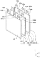
도 4 는 본 발명의 실시형태의 2 차 전지의 정극판 및 부극판의 적층 상태를 나타내는 사시도이다.
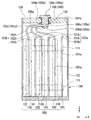
도 5 는 본 발명의 실시형태의 2 차 전지의 정극판을 나타내는 정면도이다.
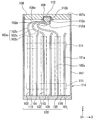
도 6 은 본 발명의 실시형태의 2 차 전지의 부극판을 나타내는 정면도이다.
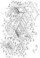
도 7 은 본 발명의 실시형태의 2 차 전지 제조 장치의 개요를 나타내는 사시도이다.
도 8 은 본 발명의 실시형태의 2 차 전지 제조 장치에 있어서, 안내 부재의 상세를 나타내는 단면도이다.
도 9 는 본 발명의 실시형태의 2 차 전지 제조 장치에 있어서, 안내 부재 착탈 수단의 상세를 나타내는 단면도이다.
도 10 은 본 발명의 실시형태의 2 차 전지 제조 장치에 있어서, 수용 수단의 상세를 나타내는 단면도이다.
도 11 은 본 발명의 실시형태의 2 차 전지의 제조 장치에 있어서, 덮개체 반송 동작을 설명하는 설명도이다.
도 12 는 본 발명의 실시형태의 2 차 전지의 제조 장치에 있어서, 안내 부재 장착 동작을 설명하는 설명도이다.
도 13 은 본 발명의 실시형태의 2 차 전지의 제조 장치에 있어서, 적층 동작을 설명하는 설명도이다.
도 14 는 본 발명의 실시형태의 2 차 전지의 제조 장치에 있어서, 매다는 동작을 설명하는 설명도이다.
도 15 는 본 발명의 실시형태의 2 차 전지의 제조 장치에 있어서, 적층 고정 동작을 설명하는 설명도이다.
도 16 은 본 발명의 실시형태의 2 차 전지의 제조 장치에 있어서, 안내 부재 제거 동작을 설명하는 설명도이다.
도 17 은 본 발명의 실시형태의 2 차 전지의 제조 장치에 있어서, 단자 고정 동작을 설명하는 설명도이다.
도 18 은 본 발명의 실시형태의 2 차 전지의 제조 장치에 있어서, 수용 동작을 설명하는 설명도이다.
도 19 는 본 발명의 실시형태의 2 차 전지의 제조 장치에 있어서, 케이스 본체의 개구부를 덮개체로 폐색하는 동작을 설명하는 설명도이다.
도 20 은 본 발명의 다른 실시형태의 2 차 전지를 나타내는 분해 측면도이다.
도 21 은 본 발명의 실시형태의 2 차 전지에 있어서, 정극판 및 부극판의 다른 예를 나타내는 정면도이다.
도 22 는 본 발명의 실시형태의 2 차 전지에 있어서, 안내 부재의 다른 예를 나타내는 측면도이다.BRIEF DESCRIPTION OF THE DRAWINGS It is a perspective view which cut | disconnected a part which shows the whole secondary battery of embodiment of this invention.
FIG. 2 is a cross-sectional view taken along the cutting line AA of FIG. 1.
3 is a cross-sectional view taken along the cutting line BB of FIG. 1.
It is a perspective view which shows the lamination state of the positive electrode plate and negative electrode plate of the secondary battery of embodiment of this invention.
It is a front view which shows the positive electrode plate of the secondary battery of embodiment of this invention.
6 is a front view showing a negative electrode plate of a secondary battery according to the embodiment of the present invention.
It is a perspective view which shows the outline | summary of the secondary battery manufacturing apparatus of embodiment of this invention.
It is sectional drawing which shows the detail of a guide member in the secondary battery manufacturing apparatus of embodiment of this invention.
It is sectional drawing which shows the detail of a guide member removal means in the secondary battery manufacturing apparatus of embodiment of this invention.
It is sectional drawing which shows the detail of a accommodating means in the secondary battery manufacturing apparatus of embodiment of this invention.
It is explanatory drawing explaining the lid body conveyance operation | movement in the manufacturing apparatus of the secondary battery of embodiment of this invention.
It is explanatory drawing explaining the guide member attachment | operation operation in the manufacturing apparatus of the secondary battery of embodiment of this invention.
It is explanatory drawing explaining the lamination | stacking operation in the manufacturing apparatus of the secondary battery of embodiment of this invention.
It is explanatory drawing explaining the operation to suspend in the manufacturing apparatus of the secondary battery of embodiment of this invention.
It is explanatory drawing explaining the lamination | stacking fixing operation in the manufacturing apparatus of the secondary battery of embodiment of this invention.
It is explanatory drawing explaining the guide member removal operation | movement in the manufacturing apparatus of the secondary battery of embodiment of this invention.
It is explanatory drawing explaining the terminal fixing operation in the manufacturing apparatus of the secondary battery of embodiment of this invention.
It is explanatory drawing explaining the accommodating operation in the manufacturing apparatus of the secondary battery of embodiment of this invention.
It is explanatory drawing explaining the operation | movement which closes the opening part of a case main body with a cover body in the manufacturing apparatus of the secondary battery of embodiment of this invention.
20 is an exploded side view showing a secondary battery according to another embodiment of the present invention.
21 is a front view illustrating another example of the positive electrode plate and the negative electrode plate in the secondary battery of the embodiment of the present invention.
It is a side view which shows another example of a guide member in the secondary battery of embodiment of this invention.
본 발명의 실시형태를 도 1 내지 도 15 에 기초하여 설명한다. 도 1 내지 도 6 은, 이 실시형태의 2 차 전지를 나타낸다. 도 1 내지 도 3 에 나타내는 바와 같이, 본 실시형태의 2 차 전지 (100) 는, 정극판 (101) 과 부극판 (102) 이 교대로 적층된 전극체 (103) 와, 그 전극체 (103) 를 수용하는 케이스 (104) 와, 그 케이스 (104) 에 내부의 정극판 (101) 및 부극판 (102) 각각과 대응하여 형성된 정극 단자 (105) 및 부극 단자 (106) 를 구비하고 있다. 케이스 (104) 는, 전극체 (103) 의 적층 방향이 되는 X 방향과 직교하는 Z 방향으로 개구부 (107a) 를 갖는 케이스 본체 (107) 와, 그 케이스 본체 (107) 의 개구부 (107a) 를 폐색하는 덮개체 (108) 를 갖는다. 그리고, 정극 단자 (105) 및 부극 단자 (106) 는, 덮개체 (108) 에 절연 슬리브 (109) 를 개재하여 장착되어 있다. 정극 단자 (105) 및 부극 단자 (106) 의 일단부 (105a, 106a) 는, 케이스 (104) 의 외부로 돌출되는 한편, 타단부 (105b, 106b) 는, 케이스 (104) 의 내부로 돌출되어, 각각 대응하는 정극판 (101) 또는 부극판 (102) 과 접속되어 있다.An embodiment of the present invention will be described based on FIGS. 1 to 15. 1 to 6 show the secondary battery of this embodiment. 1 to 3, the
정극판 (101) 및 부극판 (102) 각각은, 대략 판상이고 직사각형인 본체부 (101a, 102a) 와, 본체부 (101a, 102a) 의 가장자리 끝으로부터 돌출되는 탭 (101b, 102b, 102c) 을 갖는다. 정극판 (101) 및 부극판 (102) 의 탭 (101b, 102b, 102c) 은, 적층 방향이 되는 X 방향과 직교하고, 케이스 (104) 의 내부에 수용된 상태에서 정극 단자 (105) 및 부극 단자 (106) 를 향하는 단자 접속 방향이 되는 Z 방향으로 돌출되어 있다. 정극판 (101) 및 부극판 (102) 중, 일방의 부극판 (102) 의 본체부 (102a) 는, 절연재로 형성된 세퍼레이터 (110) 로 덮여 있고, 이로써 정극판 (101) 과 부극판 (102) 은, 그 사이에 세퍼레이터 (110) 가 배치 형성되어 절연된 상태에서 적층되어, 전극체 (103) 를 구성하고 있다.Each of the
또한, 전극체 (103) 의 가장자리 끝에는, 절연재로 이루어지는 고정용 테이프 (111) 가 복수 지점 첩착 (貼着) 되어 있고, 이로써 적층된 정극판 (101) 및 부극판 (102) 이 위치가 어긋나지 않도록 고정되어 있다. 본 실시형태에서는, 고정용 테이프 (111) 는, Y 방향 및 Z 방향과 직교하는 X 방향으로 전극판 (정극판 (101), 부극판 (102)) 이 순차 적층되어 이루어지는 전극체 (103) 의 양 가장자리 끝에, X 방향을 따라 2 지점씩 형성되어 있다.In addition, at the edge end of the
또한, 도 4 에 나타내는 바와 같이, 정극판 (101) 및 부극판 (102) 의 탭 (101b, 102b, 102c) 이 돌출되는 위치는, X 방향에서 보았을 때, 정극판 (101) 끼리, 부극판 (102) 끼리 각각 일치되어 있는 한편, 정극판 (101) 과 부극판 (102) 은 서로 상이하도록 설정되어 있다. 이로써 전극체 (103) 로서 구성된 상태에서는, 정극판 (101) 의 탭 (101b) 끼리가 묶여진 정극 탭 다발 (103a) 과, 부극판 (102) 의 탭 (102b, 102c) 끼리가 각각 묶여진 부극 탭 다발 (103b, 103c) 로 구성되어 있다. 여기에서, 각 탭 (101b, 102b, 102c) 에는 관통공 (101c, 102d, 102e) 이 형성되어 있고, 정극 탭 다발 (103a), 부극 탭 다발 (103b, 103c) 을 구성한 상태에서 서로 연통되어 있다.In addition, as shown in FIG. 4, the position where the
또한, 도 5 및 도 6 에 나타내는 바와 같이, 정극판 (101) 및 부극판 (102) 의 각 탭 (101b, 102b, 102c) 은, 각각 본체부 (101a, 102a) 의 중심선 (L101, L102) 에 대해 대략 대칭이 되도록 하여 1 개 또는 2 개 이상이 배치되어 있다. 구체적으로는 정극판 (101) 의 본체부 (101a) 에는, 1 개의 탭 (101b) 이 Z 방향을 따른 중심선 (L101) 에 대해 선대칭으로 배치되어 있다. 또한, 부극판 (102) 의 본체부 (102a) 에는, 2 개의 탭 (102b, 102c) 이 Z 방향을 따른 중심선 (L102) 에 대해 선대칭으로 배치되어 있다. 또한, 여기에서, 중심선이란, 정극판 또는 부극판의 중심을 통과하는 탭의 돌출 방향 (Z 방향) 의 선을 말한다.5 and 6, the
그리고, 도 1 및 도 2 에 나타내는 바와 같이, 정극판 (101) 의 1 개의 탭 (101b) 은, 접속용 탭으로서, 묶여져 정극 탭 다발 (103a) 을 구성하고 있다. 한편, 정극 단자 (105) 의 타단부 (105b) 의 단면으로부터는, 관통공 (101c) 에 삽입 통과되는 축부 (105c) 와, 축부 (105c) 의 선단으로부터 플랜지 형상으로 확경된 확경부 (105d) 가 형성되어 있고, 관통공 (101c) 에 축부 (105c) 가 삽입 통과된 정극 탭 다발 (103a) 은, 그 확경부 (105d) 와 타단부 (105b) 사이에 끼워 넣어져 고정되어 있다.1 and 2, one
마찬가지로, 부극판 (102) 의 2 개의 탭 (102b, 102c) 중의 일방의 탭 (102b) 은, 접속용 탭으로서, 묶여져 부극 탭 다발 (103b) 을 구성하고 있다. 한편, 부극 단자 (106) 의 타단부 (106b) 의 단면으로부터는, 관통공 (102d) 에 삽입 통과된 축부 (106c) 와, 축부 (106c) 의 선단으로부터 플랜지 형상으로 확경된 확경부 (106d) 가 형성되어 있고, 관통공 (102d) 에 축부 (106c) 가 삽입 통과된 부극 탭 다발 (103b) 은, 그 확경부 (106d) 와 타단부 (106b) 사이에 끼워 넣어져 고정되어 있다.Similarly, one of the
또한, 도 1 및 도 3 에 나타내는 바와 같이, 케이스 (104) 의 덮개체 (108) 에 있어서, 부극판 (102) 의 2 개의 탭 (102b, 102c) 중의 타방의 탭 (102c) 에 대응하는 위치에는 더미 단자 (112) 가 형성되어 있다. 더미 단자 (112) 는, 부극 단자 (106) 의 타단부 (106b) 에 상당하는 타단부 (112b) 만을 갖는 것으로서, 케이스 (104) 의 외측으로 돌출되는 선단부 (106a) 에 상당하는 구성을 갖지 않는 구성으로 되어 있다.1 and 3, a position corresponding to the
그리고, 더미 단자 (112) 의 타단부 (112b) 의 단면에는, 정극 단자 (105) 및 부극 단자 (106) 와 동일하게 축부 (112c) 및 확경부 (112d) 가 형성되어 있다. 부극판 (102) 의 2 개의 탭 (102b, 102c) 중의 타방의 탭 (102c) 은, 더미 탭으로서, 묶여져 부극 탭 다발 (103c) 을 구성하고, 관통공 (102e) 에 더미 단자 (112) 의 축부 (112c) 가 삽입 통과되어, 타단부 (112b) 와 확경부 (112d) 사이에 끼워 넣어져 고정되어 있다. 또한, 정극 단자 (105), 부극 단자 (106) 및 더미 단자 (112) 각각에 있어서의 확경부 (105d, 106d, 112d) 는, 후술하는 제조 장치에서도 설명하는 바와 같이 대응하는 축부 (105d, 106c, 112c) 의 일부를 소성 변형시킴으로써 형성되어 있다.And the
다음으로, 이와 같은 2 차 전지 (100) 를 제조하기 위한 2 차 전지 제조 장치 (1) 를 설명한다.Next, the secondary
도 7 은 이 실시형태의 2 차 전지 제조 장치 (1) 를 나타낸다. 도 7 에 나타내는 바와 같이, 이 실시형태의 2 차 전지 제조 장치 (1) 는, 정극판 (101) 및 부극판 (102) 이 재치되는 작업대 (2) 와, 그 작업대 (2) 에 전극체 (103) 를 구성하는 정극판 (101) 및 부극판 (102) 을 각각 반송하는 전극판 반송 수단 (3) 과, 작업대 (2) 로 덮개체 (108) 를 반송하는 덮개체 반송 수단 (4) 과, 작업대 (2) 위의 전극체 (103) 를 기립시키는 기립 수단 (5) 과, 적층된 정극판 (101) 및 부극판 (102) 을 일체가 되도록 고정시키는 적층 고정 수단 (6) 과, 각 탭 (101b, 102b, 102c) 을 각 단자에 고정시키는 탭 고정 수단 (7) 과, 전극체 (103) 를 케이스 (104) 의 내부에 수용시키는 수용 수단 (8) 을 구비한다.7 shows the secondary
작업대 (2) 는, 다이 본체 (21) 와, 그 다이 본체 (21) 위에 배치되고, 정극판 (101) 및 부극판 (102) 이 재치되는 재치판 (22) 을 갖는다. 재치판 (22) 은, 정극판 (101) 및 부극판 (102) 의 탭 (101b, 102b, 102c) 이 돌출되는 Z 방향을 도 7 중에 나타내는 P 방향으로 하도록 재치된다.The work table 2 has a die
그리고, 재치판 (22) 은, 덮개체 (108) 를 끼워 맞출 수 있도록 오목 형상으로 형성된 오목부를 구비한 덮개 고정부 (22a) 와, 덮개 고정부 (22a) 로부터 P 방향의 P2 측에 배치되고, 정극판 (101) 및 부극판 (102) 이 재치되는 전극판 배치부 (22b) 를 갖는다.And the mounting
덮개 고정부 (22a) 에는, 덮개체 (108) 를 끼워 맞출 수 있도록, 덮개체 (108) 의 X 방향을 따라 폭 (도 1 참조) 과 대략 동등한 P 방향의 폭의 오목부가 형성되어 있다. 이 오목부의 길이 방향은 P 방향과 직교하는 Q 방향에 있다. 덮개체 반송 수단 (4) 에 의해 덮개체 (108) 가 파지된 상태에서 이 덮개체 (108) 를 덮개 고정부 (22a) 에 끼워 맞출 수 있도록, 당해 오목부는 덮개체 (108) 의 Y 방향의 폭 (도 1 참조) 보다 큰 길이를 갖도록 설계되어 있다.In the
또한, 전극판 배치부 (22b) 에는, P 방향과 직교하는 Q 방향을 따라 홈 (22c) 이 형성되어 있다. 홈 (22c) 은, 재치판 (22) 의 양측 가장자리까지 관통하도록 형성되어 있고, 본 실시형태에서는 P 방향을 따라 2 개 배열되어 있다.Moreover, the groove |
또한, 재치판 (22) 의 P 방향 P2 측의 가장자리 끝에는, Q 방향을 따라 제 1 회전축 (51) 이 형성되어 있음과 함께, 제 1 회전축 (51) 을 회전시키는 도시되지 않은 회전 구동부 (제 1 회전 구동부) 가 형성되어 있다. 그리고, 재치판 (22) 은, 다이 본체 (21) 위에서 제 1 회전축 (51) 둘레에, 덮개 고정부 (22a) 가 상측이 되도록 하여, 적층된 전극체 (103) 와 함께 일어서도록 회전 운동할 수 있다. 제 1 회전축 (51) 과 제 1 회전 구동부로, 전극체 (103) 를 기립시키는 기립 수단 (5) 이 구성된다.Moreover, the 1st
전극판 반송 수단 (3) 은, 정극판 (101) 을 반송하는 정극판 반송부 (31) 와, 부극판 (102) 을 반송하는 부극판 반송부 (32) 를 갖고, 정극판 반송부 (31) 와 부극판 반송부 (32) 는 Q 방향으로 작업대 (2) 를 사이에 두고 양측에 형성되어 있다. 정극판 반송부 (31) 및 부극판 반송부 (32) 는, 각각 대응하는 정극판 (101) 또는 부극판 (102) 을 수취하는 전극판 수취 위치 (M1, M2) 와 작업대 (2) 의 전극판 배치부 (22b) 사이에서 이동할 수 있는 전극판 반송 아암부 (31a, 32a) 와, 전극판 반송 아암부 (31a, 32a) 의 선단에 형성되고 정극판 (101) 또는 부극판 (102) 을 착탈할 수 있는 전극판 핸드부 (31b, 32b) 와, 전극판 반송 아암부 (31a, 32a) 에 대해 전극판 핸드부 (31b, 32b) 를 상하 방향이 되는 R 방향으로 위치 조정하는 정극판 배치부 및 부극판 배치부인 전극판 상하 위치 조정부 (31c, 32c) 를 갖는다. 전극판 핸드부 (31b, 32b) 는, 예를 들어, 진공 흡착에 의해 정극판 (101) 또는 부극판 (102) 을 흡착할 수 있는 흡착 패드이다.The electrode
여기에서, 정극판 (101) 및 부극판 (102) 은, 대응하는 전극판 수취 위치 (M1, M2) 로, 예를 들어 전극판 반송용 벨트 컨베이어 (11, 12) 에 의해 순차 반송된다.Here, the
또한, 정극판 (101) 및 부극판 (102) 은, 상기 반송 전에 장척 형상의 전극 시트를 타발하여 형성된다. 이 때, 각각의 본체부와 일체 형성되는 탭에는, 당해 타발과 동시에 각각 상기 관통공이 형성된다. 구체적으로는 동일한 형으로 본체부, 탭 및 관통공이 동시에 형성된다.In addition, the
종래는 정극판과 부극판을 적층한 후에 각 탭을 묶고, 그 후, 관통공을 형성했기 때문에, 버 등이 혼입되어 전지 고장을 일으킬 가능성이 있었다. 그러나, 상기 서술한 바와 같이 정극판 (101) 및 부극판 (102) 을 형성시에 동시에 관통공을 형성하기 때문에 버의 발생을 방지할 수 있다. 이 이유를 상세하게 서술하면, 다수의 탭을 묶어 형빼기를 실시하면 버가 발생하기 쉽지만, 1 개의 탭에만 형빼기를 하여 관통공을 형성하는 경우에는, 처음부터 버는 발생하기 어렵기 때문이다.Conventionally, since the tabs were bundled after laminating the positive electrode plate and the negative electrode plate, and thereafter, through holes were formed, burrs or the like could be mixed to cause battery failure. However, since the through-holes are formed at the same time as forming the
또한, 정극판과 부극판 각각에 대해, 각각 동일한 형으로 관통공을 형성하기 때문에, 일방의 전극판에 착목했을 때, 예를 들어 적층되는 복수의 정극판 (또는 복수의 부극판) 의 각각의 탭에 있어서의 관통공의 위치를 통일할 수 있다. 즉, 복수의 정극판의 각각의 탭에 있어서의 관통공의 위치 어긋남을 방지할 수 있어, 결과적으로 양 전극판의 적층시에 위치 맞춤을 양호한 정밀도로 실시할 수 있다.In addition, since through holes are formed in the same shape for each of the positive electrode plate and the negative electrode plate, each of a plurality of positive electrode plates (or a plurality of negative electrode plates) stacked, for example, when stacked on one electrode plate. The position of the through hole in the tab can be unified. That is, the position shift of the through hole in each tab of the some positive electrode plate can be prevented, and as a result, alignment can be performed at the time of lamination | stacking of both electrode plates with good precision.
전극판 반송용 벨트 컨베이어 (11, 12) 각각은, 대응하는 정극판 반송부 (31) 또는 부극판 반송부 (32) 에 의해 정극판 (101) 또는 부극판 (102) 을 전극판 수취 위치 (M1, M2) 로부터 작업대 (2) 위로 반송, 재치했을 때, 각 탭 (101b, 102b, 102c) 이 돌출되는 방향이 P 방향의 P1 측이 되도록, 대응하는 정극판 (101) 또는 부극판 (102) 을 전극판 수취 위치 (M1, M2) 까지 반송한다.Each of the
보다 구체적으로는 본 실시형태에서는, 정극판 반송부 (31) 및 부극판 반송부 (32) 의 각 전극판 반송 아암부 (31a, 32a) 는, 각각의 회전축 둘레에 개략 90 도 회전 이동함으로써, 전극판 수취 위치 (M1, M2) 로부터 작업대 (2) 의 전극판 배치부 (22a) 위까지 이동할 수 있도록 되어 있다. 이 때문에, 이와 같은 정극판 반송부 (31) 및 부극판 반송부 (32) 의 구성에서는, 각 전극판 반송용 벨트 컨베이어 (11, 12) 는, 각각 Q 방향을 따라 작업대 (2) 로부터 멀어지는 방향으로 탭 (101b, 102b, 102c) 을 돌출시키도록 하여, 대응하는 정극판 (101) 또는 부극판 (102) 을 반송한다.More specifically, in this embodiment, each electrode plate
또한, 덮개체 반송 수단 (4) 은, 작업대 (2) 에 대해, 재치되는 정극판 (101) 및 부극판 (102) 의 탭 (101b, 102b, 102c) 이 돌출되는 P 방향의 P1 측에 인접하여 형성되어 있다. 덮개체 반송 수단 (4) 은, P 방향을 따라 배치 형성된 덮개체 반송 가이드부 (41) 와, 덮개체 반송 가이드부 (41) 를 따라, 덮개체 (108) 를 수취하는 덮개 수취 위치 (N) 와 작업대 (2) 사이에서 이동할 수 있는 덮개체 슬라이더 (42) 와, 덮개체 슬라이더 (42) 에 형성되고 덮개체 (108) 를 착탈할 수 있는 덮개체 핸드부 (43) 와, 덮개체 슬라이더 (42) 에 대해 덮개체 핸드부 (43) 를 R 방향으로 위치 조정하는 덮개체 상하 위치 조정부 (44) 를 갖는다.In addition, the cover body conveying means 4 adjoins the P1 side of the P direction which the
덮개체 핸드부 (43) 는, Q 방향을 따라 배치된 기부 (43a) 와, 그 기부 (43a) 를 따라 슬라이드할 수 있는 한 쌍의 협지편 (43b) 을 갖는다. 그리고, 기부 (43a) 를 따라 한 쌍의 협지편 (43b) 간의 서로의 이간 거리를 좁힘으로써, 덮개체 (108) 를 협지할 수 있도록 되어 있다. 또한, 덮개체 핸드부 (43) 는, 상기 정극판 (101) 이나 부극판 (102) 과 동일하게 진공 흡착에 의한 흡착 패드로 해도 된다.The lid | cover
여기에서, 덮개체 (108) 는, 덮개 수취 위치 (N) 에, 예를 들어 덮개체용 벨트 컨베이어 (13) 에 의해 순차 반송된다. 또, 덮개체 (108) 의 덮개체용 벨트 컨베이어 (13) 에 의해 반송될 때의 자세는, 조립했을 때의 내면 (108a) 이 상방이 되도록 배치된다.Here, the
또한, 덮개체용 벨트 컨베이어 (13) 에 의해 덮개 수취 위치 (N) 로 반송될 때의 덮개체 (108) 의 정극 단자 (105), 부극 단자 (106) 및 더미 단자 (112) 각각은, 확경부 (105d, 106d, 112d) 를 구비하고 있지 않아, 소성하여 확경부 (105d, 106d, 112d) 가 되기 전의 선단 부분을 포함하여 타단부 (105b, 106b) 의 단면으로부터 축부 (105c, 106c, 112c) 가 돌출된다. 그리고, 돌출된 이들 축부의 선단면으로부터는 축부 (105c, 106c, 112c) 보다 소직경으로 소성하여 확경부 (105d, 106d, 112d) 의 일부가 되는 선단 소직경부 (105e, 106e, 112e) 가 형성되어 있다.In addition, each of the
또, 적층 고정 수단 (6) 은, 기립 수단 (5) 에 의해 기립된 전극체 (103) 를 임시 고정시키는 임시 고정 수단 (61) 과, 임시 고정된 전극체 (103) 를 고정용 테이프 (111) 로 고정시키는 테이프 첩착 수단 (62) 으로 구성되어 있다.Moreover, the lamination | stacking fixing means 6 fixes the temporary fixing means 61 which temporarily fixes the
임시 고정 수단 (61) 은, 작업대 (2) 의 다이 본체 (21) 위에서 재치판 (22) 옆 (P 방향의 P2 측) 에 배치된 협지판 (63) 과, 그 협지판 (63) 의 P 방향의 P1 측의 가장자리 끝에 Q 방향을 따라 형성되고 다이 본체 (21) 위에서 협지판 (63) 을 회전 운동할 수 있게 하는 제 2 회전축 (64) 과, 제 2 회전축 (64) 을 회전 구동시키는 도시되지 않은 회전 구동부 (제 2 회전 구동부) 를 갖는다. 협지판 (63) 은, 제 2 회전축 (64) 둘레를 회전했을 때에, 기립 수단 (5) 에 의해 기립된 재치판 (22) 사이에서 재치판 (22) 위의 전극체 (103) 를 끼워 넣을 수 있는 위치에 형성되어 있다. 또한, 협지판 (63) 위에는, 재치판 (22) 에 형성되는 홈 (22c) 과 대향하는 위치에 동일하게 홈 (63a) 이 형성되어 있다. 당해 홈 (63a) 도 Q 방향을 따라 양 가장자리 끝까지 관통하도록 형성되어 있다.The temporary fixing means 61 is the holding
또, 테이프 첩착 수단 (62) 은, 작업대 (2) 를 사이에 두고 Q 방향 양측에 각각 형성되어 있고, 전극체 (103) 에 고정용 테이프 (111) 를 첩착하는 첩착 기구 (65) 와, 첩착 기구 (65) 를 Q 방향을 따라 작업대 (2) 를 향하여 진퇴시키는 진퇴 기구 (66) 를 갖는다. 진퇴 기구 (66) 는, Q 방향을 따라 배치 형성된 진퇴 가이드부 (66a) 와, 선단에 첩착 기구 (65) 가 형성되고, 진퇴 가이드부 (66a) 에 의해 Q 방향을 따라 진퇴하는 진퇴 부재 (66b) 를 갖는다. 진퇴 부재 (66b) 에는, 재치판 (22) 및 협지판 (63) 의 2 개씩의 홈 (22c, 63a) 과 대응하여 2 개의 첩착 기구 (65) 가 상하로 배열되도록 형성되어 있다.Moreover, the tape sticking means 62 is formed in the Q direction both sides with the
첩착 기구 (65) 는, 전극체 (103) 의 두께와 대응하는 길이로 설정되고 또한 P 방향을 따라 배치 형성된 기편 (基片)(65a) 과, 기편 (65a) 의 양단으로부터 Q 방향으로 돌출되는 한 쌍의 돌편 (突片) (65b, 65b) 을 갖고, 기편 (65a) 및 한 쌍의 돌편 (65b, 65b) 에 의해 전체적으로 U 자 형상으로 형성되어 있다.The
그리고, 진퇴 기구 (66) 에 의해 첩착 기구 (65) 가 작업대 (2) 를 향하여 진출함으로써, 기립 수단 (5) 에 의해 기립한 재치판 (22) 의 홈 (22c), 및 재치판 (22) 에 대향하도록 회전 운동시킨 협지판 (63) 의 홈 (63a) 각각에 돌편 (65b) 을 삽입시킬 수 있도록 되어 있다. 또, 돌편 (65b) 은, 기편 (65a) 을 따라 슬라이드할 수 있도록 구성되어 있다.And the groove |
첩착 기구 (65) 를 형성하는 U 자 내측이 되는 부분에는, 일방의 돌편 (65b) 으로부터 기편 (65a) 을 거쳐 타방의 돌편 (65b) 에 걸치도록, 또한, 내측에 점착부가 향하도록 하여 고정용 테이프 (111) 가 배치되어 있다.In the part which becomes the U-shaped inner side which forms the
이 구성에 의해, 상기 서술한 바와 같이 홈 (63a) 각각에 돌편 (65b) 이 삽입된 후, 쌍의 돌편 (65b) 이 서로 슬라이드되어 전극체 (103) 를 사이에 두고 압압됨으로써, 전극체 (103) 에 고정용 테이프 (111) 을 첩착할 수 있다.According to this configuration, after the
또, 협지판 (63) 에 있어서, 재치판 (22) 에 형성되는 덮개 고정부 (22a) 와 대응하는 위치에는, 덮개 고정부 (22a) 에 고정되는 덮개체 (108) 의 정극 단자 (105), 부극 단자 (106) 및 더미 단자 (112) 에 대응하는 위치에, 후술하는 안내 부재 (14) 를 착탈시키기 위한 안내 부재 착탈 수단 (9) 이 각각 형성되어 있다.Moreover, in the clamping
여기에서, 도 8 에 나타내는 바와 같이, 안내 부재 (14) 는, 본 실시형태에서는 원추형으로 형성되어 있고, 기단이 되는 저면 (14a) 에는, 아직 확경부 (105d, 106d, 112d) 가 형성되어 있지 않은 덮개체 (108) 의 정극 단자 (105), 부극 단자 (106) 및 더미 단자 (112) 의 각각의 선단 소직경부 (105e, 106e, 112e) 에 끼워 맞출 수 있는 오목부 (14b) 가 형성되어 있다. 또, 안내 부재 (14) 의 저면 (14a) 에 있어서의 직경은, 각 축부 (105d, 106c, 112c) 의 직경과 대략 동일하게 설정되어 있다.Here, as shown in FIG. 8, the
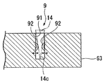
도 9 에 나타내는 바와 같이, 안내 부재 착탈 수단 (9) 은, 구체적으로는 안내 부재 (14) 의 선단부 (14c) 가 삽입되는 피삽입부 (91) 와, 그 피삽입부 (91) 내에 형성되어 삽입된 안내 부재 (14) 의 선단부 (14c) 를 협지할 수 있는 척부 (92) 를 갖는다. 그리고, 도 7 에 나타내는 바와 같이, 기립 수단 (5) 에 의해 기립한 재치판 (22) 과 협지판 (63) 을 대향시킨 상태에서, 피삽입부 (91) 는, 재치판 (22) 의 덮개 고정부 (22a) 에 끼워 맞춰진 덮개체 (108) 의 정극 단자 (105), 부극 단자 (106) 및 더미 단자 (112) 에 대향하고, 이들 각 단자의 안내 부재 (14) 가 각각 대응하는 피삽입부 (91) 에 삽입되기 때문에, 각 단자와 피삽입부 (91) 내부의 척부 (92) 사이에서 안내 부재 (14) 를 주고 받을 수 있도록 되어 있다.As shown in FIG. 9, the guide member detachment means 9 is specifically provided in the to-
도 7 에 나타내는 바와 같이, 탭 고정 수단 (7) 은, 재치판 (22) 의 P 방향의 P1 측에 형성된 가압판 (7a) 과, 재치판 (22) 의 P 방향의 P1 측의 가장자리 끝에 형성되고 또한 Q 방향을 축심으로 하여 가압판 (7a) 을 회전시키는 제 3 회전축 (7b) 과, 제 3 회전축 (7b) 을 회전 구동시키는 도시되지 않은 회전 구동부 (제 3 회전 구동부) 를 갖는다.As shown in FIG. 7, the tab fixing means 7 is formed at the edge end of the
그리고, 후술하는 바와 같이 정극판 (101) 및 부극판 (102) 이 재치판 (22) 에 적층되고 또한 안내 부재 (14) 가 정극 단자 (105), 부극 단자 (106) 및 더미 단자 (112) 로부터 떼어내어진 후에, 제 3 회전축 (7b) 둘레에 가압판 (7a) 을 회전시킴으로써, 덮개 고정부 (22a) 에 고정된 덮개체 (108) 의 정극 단자 (105), 부극 단자 (106) 및 더미 단자 (112) 의 축부 (105d, 106c, 112c) 의 선단 부분을 가압판 (7a) 에 의해 압압하고, 코킹하여, 확경부 (105d, 106d, 112d) 를 형성할 수 있도록 되어 있다.As described later, the
수용 수단 (8) 은, P 방향을 따라 배치 형성된 수용용 가이드부 (81) 와, 수용용 가이드부 (81) 를 따라, 작업대 (2) 위로부터 전극체 (103) 를 케이스 본체 (107) 에 수용하는 수용 위치 (S) 까지 이동할 수 있는 수용용 슬라이더 (82) 와, 수용용 슬라이더 (82) 에 형성되고 덮개체 (108) 를 착탈할 수 있는 수용용 핸드부 (83) 와, 수용용 슬라이더 (82) 에 대해 수용용 핸드부 (83) 를 R 방향으로 위치 조정하는 수용용 상하 위치 조정부 (84) 를 갖는다.The accommodating means 8 carries the
여기에서, 케이스 본체 (107) 는, 수용 위치 (S) 에, 예를 들어 케이스 본체용 벨트 컨베이어 (16) 에 의해 순차 반송된다. 또, 케이스 본체 (107) 의 케이스 본체용 벨트 컨베이어 (16) 에 의해 반송될 때의 자세는, 개구부 (107a) 가 상방을 향하도록 설정되어 있다.Here, the case
수용용 핸드부 (83) 는, Q 방향을 따라 배치된 기부 (83a) 와, 당해 기부 (43a) 를 따라 슬라이드할 수 있는 한 쌍의 협지편 (83b) 을 갖는다. 그리고, 기부 (43a) 를 따라 한 쌍의 협지편 (83b) 의 서로의 이간 거리를 좁힘으로써, 덮개체 (108) 를 Q 방향으로 협지할 수 있도록 되어 있다.The
여기에서, 도 10 에 나타내는 바와 같이, 수용용 핸드부 (83) 의 한 쌍의 협지편 (83b) 각각에는, 덮개체 (108) 를 협지하는 위치에 회전할 수 있도록 지지된 맞닿음판 (83c) 이 배치되어 있다. 이 때문에, 한 쌍의 협지편 (83b) 으로 덮개체 (108) 를 협지할 때에는, 맞닿음판 (83c) 이 덮개체 (108) 에 각각 맞닿게 되어, 맞닿음판 (83c) 의 회전에 의해 협지편 (83b) 에 대한 덮개체 (108) 의 방향을 변경할 수 있도록 되어 있다.Here, as shown in FIG. 10, the
다음으로, 본 실시형태의 2 차 전지 (100) 의 제조 장치 (1) 의 동작에 대하여 도 11 내지 도 18 을 참조하여 설명한다.Next, operation | movement of the
먼저, 준비 공정으로서, 상기 정극판 (101) 및 부극판 (102) 을 준비함과 함께, 덮개체 (108) 및 케이스 본체 (107) 를 준비한다. 그리고, 준비된 정극판 (101) 및 부극판 (102) 은, 각각 대응하는 전극판 반송용 벨트 컨베이어 (11, 12) 에 의해 각 전극판 수취 위치 (M1, M2) 로 순차 반송된다. 또한, 준비된 덮개체 (108) 는, 덮개체용 벨트 컨베이어 (13) 에 의해 덮개 수취 위치 (N) 로 순차 반송된다. 또한, 준비된 케이스 본체 (107) 는, 케이스 본체용 벨트 컨베이어 (16) 에 의해 수용 위치 (S) 로 순차 반송된다.First, as a preparation process, the said
여기에서, 덮개 수취 위치 (N) 로 반송되는 덮개체 (108) 는, 정극 단자 (105), 부극 단자 (106) 및 더미 단자 (112) 가 확경부 (105d, 106d, 112d) 를 구비하고 있지 않아, 축부 (105c, 106c, 112c) 의 단면으로부터 선단 소직경부 (105e, 106e, 112e) 가 돌출된 구성으로 되어 있다.Here, in the
그리고, 도 11 에 나타내는 바와 같이, 덮개체 반송 수단 (4) 에 의해 덮개 수취 위치 (N) 로 반송된 덮개체 (108) 를 작업대 (2) 의 재치판 (22) 의 덮개 고정부 (22a) 까지 반송한다. 즉, 덮개 수취 위치 (N) 에서, 덮개체 반송 수단 (4) 의 한 쌍의 협지편 (43b) 에 의해 덮개체 (108) 를 협지한다. 그리고, 협지한 덮개체 (108) 를 P 방향을 따라 작업대 (2) 의 재치판 (22) 에 있어서 덮개 고정부 (22a) 의 상방까지 반송한다. 그리고, 덮개체 상하 조정부 (44) 에 의해 덮개체 (108) 를 강하시킴으로써, 덮개체 (108) 는 덮개 고정부 (22a) 에 내면 (108a) 을 상방으로 받도록 하여 끼워 맞춰져 고정된다.And as shown in FIG. 11, the
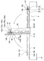
다음으로, 도 12 에 나타내는 바와 같이, 작업대 (2) 위의 덮개체 (108) 의 정극 단자 (105), 부극 단자 (106) 및 더미 단자 (112) 각각에 안내 부재 (14) 를 장착한다. 안내 부재 (14) 는, 협지판 (63) 에 형성된 안내 부재 착탈 수단 (9) 의 피삽입부 (91) 에 선단부 (14c) 가 삽입되고 척부 (92) 에 의해 협지된 상태에 있다. 그리고, 기립 수단 (5) 의 제 1 회전축 (51) 둘레에 재치판 (22) 을 회전시킴과 함께, 임시 고정 수단 (61) 의 제 2 회전축 (64) 둘레에 협지판 (63) 을 회전시켜, 재치판 (22) 과 협지판 (63) 을 대향시킨다. 이로써, 피삽입부 (91) 에 삽입된 안내 부재 (14) 의 저면 (14a) 의 오목부 (14b) 가, 덮개 고정부 (22a) 에 고정된 덮개체 (108) 의 정극 단자 (105), 부극 단자 (106) 및 더미 단자 (112) 의 각각의 선단 소직경부 (105e, 106e, 112e) 에 끼워 맞춰진다. 이 상태에서, 안내 부재 착탈 수단 (9) 의 척부 (92) 에 의한 안내 부재 (14) 가 협지된 상태를 해제한다.Next, as shown in FIG. 12, the
그리고, 제 2 회전축 (64) 둘레에 회전시켜 협지판 (63) 을 기립한 상태로부터 원래의 상태로 되돌림으로써, 안내 부재 (14) 는, 각 선단 소직경부 (105e, 106e, 112e) 에 장착된 채로 피삽입부 (91) 로부터 이탈된다. 그리고, 재치판 (22) 도 제 1 회전축 (51) 둘레에 회전시켜, 기립한 상태로부터 원래의 상태로 되돌린다.And the
다음으로, 도 13 에 나타내는 바와 같이, 적층 공정으로서, 서로의 탭 (101b, 102b, 102c) 이 동일 방향 (P 방향의 P1측) 으로 돌출되도록 하여 정극판 (101) 및 부극판 (102) 을 교대로 적층시켜 간다. 즉, 먼저, 전극판 반송 수단 (3) 의 정극판 반송부 (31) 와 부극판 반송부 (32) 중, 예를 들어 정극판 반송부 (31) 가 구동된다. 정극판 반송부 (31) 는, 대응하는 전극판 수취 위치 (M1) 로 반송되는 정극판 (101) 을 전극판 핸드부 (31b) 로 파지하고 나서 전극판 반송 아암부 (31a) 를 회전시킴으로써, 작업대 (2) 의 전극판 배치부 (22b) 상방까지 정극판 (101) 을 이동시킨다.Next, as shown in FIG. 13, as a lamination process, the
그리고, 이 상태에서, 전극판 상하 위치 조정부 (31c) (정극판 배치부) 에 의해, 파지한 정극판 (101) 을 전극판 배치부 (22b) 에 강하시킴으로써, 정극판 (101) 은, 탭 (101b) 의 관통공 (101c) 이 정극 단자 (105) 의 축부 (105d) 에 삽입되면서 전극판 배치부 (22b) 에 배치된다. 이 때, 정극 단자 (105) 는 안내 부재 (14) 가 장착되어 선단이 날카로워진 형상임과 함께, 정극 단자 (105) 측으로 감에 따라 확경되어 감으로써, 탭 (101b) 의 관통공 (101c) 에 최소한의 반송 정밀도로 용이하게 정극 단자 (105) 의 축부 (105d) 를 삽입할 수 있게 하면서, 정확하게 위치 조정할 수 있게 된다.In this state, the
다음으로, 부극판 반송부 (32) 가 구동된다.Next, the negative electrode
부극판 반송부 (32) 는, 대응하는 전극판 수취 위치 (M1) 로 반송되는 부극판 (102) 을 전극판 핸드부 (32b) 로 파지하고 나서 전극판 반송 아암부 (32a) 를 회전시킴으로써, 작업대 (2) 의 전극판 배치부 (22b) 상방까지 정극판 (101) 을 이동시킨다.The negative electrode
그리고, 이 상태에서, 전극판 상하 위치 조정부 (32c) (부극판 배치부) 에 의해, 파지한 부극판 (102) 을 전극판 배치부 (22b) 에 강하시킴으로써, 부극판 (102) 은, 탭 (102b) 의 관통공 (102d) 이 부극 단자 (106) 의 축부 (106c) 에, 탭 (102c) 의 관통공 (102e) 이 더미 단자 (112) 의 축부 (112c) 에 각각 삽입되면서 전극판 배치부 (22b) 에 배치된다.In this state, the
이 때에도 부극 단자 (106) 및 더미 단자 (112) 각각에 안내 부재 (14) 가 장착되어 있음으로써, 탭 (102b, 102c) 의 관통공 (102d, 102e) 에 최소한의 반송 정밀도로 용이하게 부극 단자 (106) 의 축부 (106c, 112c) 를 삽입할 수 있게 하면서, 정확하게 위치 조정할 수 있게 된다.Also in this case, the
그리고, 정극판 반송부 (31) 및 부극판 반송부 (32) 에 의한 정극판 (101) 및 부극판 (102) 의 반송을 교대로 반복함으로써, 재치판 (22) 위에는, 각각 탭 (101b, 102b, 102c) 의 관통공 (101c, 102d, 102e) 에, 대응하는 정극 단자 (105), 부극 단자 (106) 또는 더미 단자 (112) 의 축부 (105d, 106c, 112c) 가 삽입 통과된 상태에서, 정극판 (101) 과 부극판 (102) 이 교대로 적층되어 전극체 (13) 가 구성된다.And by repeating the conveyance of the
다음으로, 도 14 에 나타내는 바와 같이, 전극체 (103) 의 정극 탭 다발 (103a) 및 부극 탭 다발 (103b, 103c) 을 각각 지지하여, 정극판 (101) 및 부극판 (102) 을 매단다. 즉, 기립 수단 (5) 은, 제 1 회전축 (51) 둘레에 재치판 (22) 를 회전시켜 기립시킨다. 이 때, 정극판 (101) 및 부극판 (102) 의 각 탭 (101b, 102b, 102c) 의 관통공 (101c, 102d, 102e) 에 정극 단자 (105), 부극 단자 (106) 및 더미 단자 (112) 의 각 축부 (105d, 106c, 112c) 가 삽입 통과되어 있음으로써, 정극 탭 다발 (103a) 및 부극 탭 다발 (103b, 103c) 각각은, 각 축부 (105d, 106c, 112c) 에 지지된 상태에서 매달린다.Next, as shown in FIG. 14, the positive
또한, 기립 수단 (5) 에 의한 재치판 (22) 의 기립 상태로서는, 대략 연직 상태가 되도록 해도 되지만, 정극판 (101) 과 부극판 (102) 의 적층 상태를 유지시키기 위해 약간 경사진 상태인 것이 바람직하다. 여기에서, 정극판 (101) 및 부극판 (102) 각각에 있어서, 탭 (101b, 102b, 102c) 은, 정극판 (101) 및 부극판 (102) 의 중심선 (L101, L102) 에 대해 선대칭으로 형성되어 있다. 이 때문에, 정극 탭 다발 (103a) 및 부극 탭 다발 (103b, 103c) 로 지지되어 매달린 정극판 (101) 및 부극판 (102) 각각은, 중력의 작용에 의해, 서로의 중심선 (L101, L102) 방향이 일치하도록 자동적으로 위치 결정된다. 서로의 중심선의 방향뿐만 아니라 위치도 일치 또는 중첩되도록 하면, 정극판 (101) 과 부극판 (102) 은 서로의 대략 중심 위치에서 중첩되도록 위치 결정되어 적층되기 때문에, 적층 어긋남의 영향을 감소 또는 방지하는 관점에서 보다 바람직하다.In addition, although the standing state of the mounting
이 때, 정극판 (101) 및 부극판 (102) 의 탭은 서로 중첩되지 않는 위치에 배치되어 있기 때문에, 정극판 (101) 및 부극판 (102) 의 탭이 접촉하여 단락되는 것이 방지된다.At this time, since the tabs of the
여기에서, 기립 수단 (5) 은, 예를 들어 진동 모터 등의 기진부를 갖는 것으로 해도 된다. 이와 같이 기진부를 구비함으로써, 재치판 (22) 위에서 정극판 (101) 및 부극판 (102) 을 위치 결정할 때, 진동을 부여할 수 있어, 그 진동에 의해 서로 적층된 정극판 (101) 과 부극판 (102) 사이에 작용하는 마찰력을 저감시켜 위치 결정을 보다 효과적으로 실시하는, 즉 적층 어긋남을 효과적으로 방지할 수 있다.Here, the standing means 5 may have vibrating parts, such as a vibration motor, for example. By providing the vibrating portion as described above, when positioning the
다음으로, 정극판 (101) 및 부극판 (102) 이 적층된 상태에서 일체가 되도록 고정시킨다.Next, the
먼저, 도 14 에 나타내는 바와 같이, 적층 고정 수단 (6) 에 있어서 임시 고정 수단 (61) 에 의해 전극체 (103) 의 임시 고정을 실시한다. 즉, 제 2 회전축 (64) 둘레에 협지판 (63) 을 회전시켜 재치판 (22) 과 대향시킴으로써, 재치판 (22) 과 협지판 (63) 사이에서 전극체 (103) 를 끼워 넣는다. 이로써 전극체 (103) 를 구성하는 정극판 (101) 및 부극판 (102) 은, 상기 매달음에 의한 위치 결정 실시 후에 있어서의 적층 상태로부터 변위되지 않도록 임시 고정된다.First, as shown in FIG. 14, the temporary fixing means 61 is temporarily fixed in the laminated fixing means 6. That is, the
다음으로, 도 15 에 나타내는 바와 같이, 테이프 첩착 수단 (62) 에 의해 전극체 (103) 에 고정용 테이프 (111) 를 첩착함으로써 전극체 (103) 를 일체로 한다. 즉, 전극체 (103) 가 재치판 (22) 및 협지판 (63) 에 협지된 상태인 채, 테이프 첩착 수단 (62) 의 진퇴 기구 (66) 에 의해, 첩착 기구 (65) 를 작업대 (2) 를 향하여 진출시켜 돌편 (65b) 을 재치판 (22) 및 협지판 (63) 의 각 홈 (22c, 63a) 에 삽입시킨다.Next, as shown in FIG. 15, the
이 상태에서 한 쌍의 돌편 (65b) 끼리의 폭을 좁힘으로써, 돌편 (65b) 사이에 배치된 전극체 (103) 의 가장자리 끝에 U 자 상으로 고정용 테이프 (111) 가 첩착되고, 전극체 (103) 는, 상기 매달음에 의한 위치 결정 실시 후에 있어서의 적층 상태인 채로 일체가 되도록 고정된다. In this state, by narrowing the width of the pair of
다음으로, 덮개체 (108) 의 정극 단자 (105), 부극 단자 (106) 및 더미 단자 (112) 각각으로부터 안내 부재 (14) 를 떼어낸다. 즉, 전극체 (103) 를 재치판 (22) 및 협지판 (63) 으로 협지한 상태에서는, 안내 부재 (14) 의 선단부 (14c) 는, 안내 부재 착탈 수단 (9) 의 피삽입부 (91) 에 삽입된 상태에 있다 (도 14 참조). 그리고, 이 상태인 채, 척부 (92) 에 의해 안내 부재 (14) 를 협지시킨다. 다음으로, 제 1 회전축 (51) 둘레에 협지판 (63) 을 회전시켜 재치판 (22) 으로부터 이간시키도록 하면, 도 16 에 나타내는 바와 같이, 척부 (92) 에 협지된 안내 부재 (14) 는, 장착되어 있던 정극 단자 (105), 부극 단자 (106) 및 더미 단자 (112) 로부터 이탈되어 협지판 (63) 과 함께 퇴피되게 되고, 재치판 (22) 측에는, 정극 탭 다발 (103a) 및 부극 탭 다발 (103b, 103c) 로부터 축부 (105d, 106c, 112c) 의 선단측이 돌출된 상태가 된다. 또한, 협지판 (63) 과 함께 퇴피된 안내 부재 (14) 는, 다른 새로운 2 차 전지 (100) 의 조립시에 이용된다.Next, the
그리고, 기립 수단 (5) 의 제 1 회전축 (51) 둘레에 재치판 (22) 을 회전시켜, 재치판 (22) 을 다이 본체 (21) 위에 재치된 상태로 되돌린다.Then, the mounting
다음으로, 도 17 에 나타내는 바와 같이, 정극 탭 다발 (103a) 및 부극 탭 다발 (103b, 103c) 을 대응하는 각 단자에 고정시킨다. 즉, 탭 고정 수단 (7) 의 가압판 (7a) 을 제 3 회전축 (7b) 둘레에 회전시켜 재치판 (22) 과 대향하도록 한다. 이로써, 탭 (101b, 102b, 102c) 으로부터 돌출된 축부 (105d, 106c, 112c) 의 선단측은 선단 소직경부 (105e, 106e, 112e) 도 포함하여 압압되어 소성변형되어, 확경부 (105d, 106d, 112d) 가 형성된다. 이 때문에, 각 탭 (101b, 102b, 102c) 은, 관통공 (101c, 102d, 102e) 에, 대응하는 축부 (105d, 106c, 112c) 가 삽입 통과된 채 확경부 (105d, 106d, 112d) 와 타단부 (105c, 106c, 112c) 사이에 끼워 넣어져 고정된 상태가 된다.Next, as shown in FIG. 17, the positive
다음으로, 전극체 (103) 를 케이스 본체 (107) 에 수용한다. 즉, 도 18에 나타내는 바와 같이, 수용 수단 (8) 에 있어서 수용용 핸드부 (83) 의 한 쌍의 협지편 (83b) 을, 덮개 고정부 (22a) 에 있어서, 덮개체 (108) 의 Q 방향 양측에 형성된 간극에 삽입하여, 덮개체 (108) 를 협지시킨다. 그리고, 수용용 상하 위치 조정부 (84) 에 의해 수용용 핸드부 (83) 를 상방으로 이동시킴으로써, 수용용 핸드부 (83) 에 협지된 덮개체 (108) 는, 덮개 고정부 (22a) 로부터 이탈되고, 또한 덮개체 (108) 의 정극 단자 (105), 부극 단자 (106) 및 더미 단자 (112) 에 고정된 정극 단자 (105) 및 부극 단자 (106) 로 이루어지는 전극체 (103) 도 이탈된다. 이 때문에, 덮개체 (108) 및 전극체 (103) 는, 수용 수단 (8) 에 의해, 수용용 핸드부 (83) 로 파지된 상태에서 매달려 P 방향을 따라 이동하여, 수용 위치 (S) 까지 반송된다. 그리고, 수용 위치 (S) 에 있어서, 케이스 본체 (107) 상방으로부터 수용용 상하 위치 조정부 (84) 에 의해 강하됨으로써, 전극체 (103) 는, 케이스 본체 (107) 의 개구부 (107a) 로부터 내부로 삽입되어 간다.Next, the
그리고, 도 19 에 나타내는 바와 같이, 또한 수용용 상하 위치 조정부 (84) 에 의해 전극체 (103) 및 덮개체 (108) 를 강하시킴으로써, 전극체 (103) 가 케이스 본체 (107) 에 완전히 수용됨과 함께, 정극 탭 다발 (103a) 및 부극 탭 다발 (103b, 103c) 도 접히면서 케이스 본체 (107) 의 내부에 수용되어, 덮개체 (108) 가 케이스 본체 (107) 의 개구부 (107a) 에 배치된다. 이 때, 덮개체 (108) 는, 상기한 바와 같이 수용 수단 (8) 의 수용용 핸드부 (83) 에 형성된 맞닿음판 (83c) 에 의해 수용용 핸드부 (83) 에 대해 회전할 수 있기 때문에, 케이스 본체 (107) 의 개구부 (107a) 를 닫도록 방향을 바꾸면서, 그 개구부 (107a) 에 배치되고, 케이스 본체 (107) 가 폐색된다.And as shown in FIG. 19, the
이상과 같이, 본 실시형태의 2 차 전지의 제조 장치 (1) 에 의하면, 정극판 (101) 및 부극판 (102) 으로서, 본체부 (101a, 102a) 의 중심선 (L101, L102) 에 대해 선대칭이 되도록 하여 탭이 1 개 또는 2 개 이상 형성되어 있는 것을 사용하여, 기립 수단 (5) 에 의해 상기 매달음을 실시함으로써, 정극판 (101) 과 부극판 (102) 의 크기가 상이해도, 적층 어긋남 없이 양호한 정밀도로, 또한, 효율적으로 적층하여 2 차 전지 (100) 를 제조할 수 있다.As described above, according to the
또한, 정극판 (101) 및 부극판 (102) 을 적층시키는 작업대 (2) 의 재치판 (22) 에 덮개 고정부 (22a) 가 형성되어 있음으로써, 덮개체 반송 수단 (4) 에 의해 반송한 덮개체 (108) 를 작업대 (2) 위에서 덮개 고정부 (22a) 에 고정시킬 수 있다. 이 때문에, 전극판 반송 수단 (3) 에 의해 정극판 (101) 및 부극판 (102) 을 반송하고, 각각의 탭 (101b, 102b, 102c) 을 덮개체 (108) 위에 고정시킬 수 있게 된다.Moreover, since the
그리고, 상기 매달음시, 기립 수단 (5) 에 의해, 정극판 (101) 및 부극판 (102) 을, 덮개체 (108) 에 지지된 상태인 채 서로 위치 결정시킬 수 있다.At the time of the suspension, the standing means 5 allows the
또한, 전극판 반송 수단 (3) 으로 정극판 (101) 및 부극판 (102) 을 반송하여, 각각의 탭 (101b, 102b, 102c) 의 관통공 (101c, 102d, 102e) 에, 대응하는 정극 단자 (105) 또는 부극 단자 (106) 를 삽입 통과시킬 때, 이들 정극 단자 (105) 및 부극 단자 (106) 에 추 형상의 안내 부재 (14) 가 고정되어 있음으로써, 최소한의 반송 정밀도로 용이하게, 탭 (101b, 102b, 102c) 의 관통공 (101c, 102d, 102e) 에 정극 단자 (105) 또는 부극 단자 (106) 를 삽입 통과시킬 수 있다. 또한, 정극판 (101) 및 부극판 (102) 을 적층한 후에는, 안내 부재 착탈 수단 (9) 에 의해 안내 부재 (14) 를 떼어냄으로써, 그 후의 탭 고정 수단 (7) 의 동작에 있어서 안내 부재 (14) 가 지장이 되는 경우도 없다.In addition, the
또한, 상기한 바와 같이, 본 발명의 2 차 전지 (100) 및 2 차 전지 제조 장치 (1) 의 실시형태에 대하여 설명했지만, 이들은 일례에 지나지 않고, 여러가지 다른 실시형태를 생각할 수 있다.In addition, as mentioned above, although embodiment of the
도 20 은, 2 차 전지에 대한 다른 실시형태를 나타내고 있다. 도 20 에 나타내는 바와 같이, 이 실시형태의 2 차 전지 (200) 에서는, 케이스 (201) 가, 적층 방향 X 의 일방측에 개구부 (202a) 를 갖는 케이스 본체 (202) 와, 개구부 (202a) 를 폐색하는 덮개체 (203) 를 갖는다. 덮개체 (203) 는, 개구부 (202a) 를 폐색하는 구성이기 때문에, 케이스 본체 (202) 에 수용되는 정극판 (101) 및 부극판 (102) 보다 큰 면을 갖는다. 그리고, 본 실시형태에서도, 덮개체 (203) 에, 정극 단자 (105), 부극 단자 (106) 및 더미 단자 (112) 가 형성되어 있다. 여기에서는, 덮개체 (203) 를 관통하는 정극 단자 (105), 부극 단자 (106) 및 더미 단자 (112) 도 X 방향으로 돌출된다.20 shows another embodiment of the secondary battery. As shown in FIG. 20, in the
도 20 에 나타내는 2 차 전지 (200) 에서는, 탭 (101b, 102b, 102c) 뿐만 아니라, 본체부 (101a, 102a) 도 덮개체 (203) 위에 재치하도록 하여 정극판 (101) 및 부극판 (102) 을 교대로 적층해 갈 수 있다. 이 때문에, 덮개체 (203) 와 전극체 (103) 를 일체로 하여 보다 용이하게 취급할 수 있다.In the
또한, 케이스 본체 (107) 에 전극체 (103) 를 수용 공정할 때, 매단 전극체 (103) 를 반송?삽입할 필요는 없어, 덮개체 (202) 의 상방으로부터 케이스 본체 (202) 를 씌우는 것만으로 좋기 때문에, 작업이 보다 용이해진다.In addition, when carrying out the process of accommodating the
또한, 덮개체 (203) 로 케이스 본체 (202) 의 개구부 (202a) 를 폐색한 후에도, 탭 (101b, 102b, 102c) 은, 작게 접히지 않고, 방향을 바꾸지 않고 배치 형성시킬 수 있다. 이 때문에, 케이스 (201) 에 수용된 상태에서, 탭 (101b, 102b, 102c) 에 휨이 작용하여 인장 응력이나 압축 응력이 발생하여 파손될 우려도 없다.Moreover, even after the
또한, 상기 실시형태에 있어서, 정극판 (101) 은, 하나의 탭 (101b) 을 갖고, 부극판 (102) 은, 2 개의 탭 (102b, 102c) 을 갖는 것으로 했지만, 이것에 한정되지 않는다. 도 21 에 나타내는 바와 같이, 부극판 (102) 뿐만 아니라, 정극판 (101) 도 2 개의 탭 (101b, 101d) 을 갖고, 그 일방을 접속용 탭으로 하고, 타방을 더미 탭으로 해도 된다.In addition, in the said embodiment, although the
나아가서는, 탭은 2 개에 한정되지 않고, 3 개 이상으로 해도 된다. 적어도 정극판, 부극판은, 적층되었을 때 서로 위치가 상이한, 즉 서로 중첩되지 않는 1 개 또는 2 개 이상의 탭을 갖고 있고, 이들 각 전극판의 각 중심선 (L101, L102) 에 대해 선대칭이 되도록 배치되어 있으면 된다.Further, the tab is not limited to two, but may be three or more. At least the positive electrode plate and the negative electrode plate have one or two or more tabs that are different from each other when stacked, that is, do not overlap each other, and are arranged so as to be line-symmetric with respect to the respective centerlines L101 and L102 of these electrode plates. It is enough.
이 구성에 의해, 상기와 같이 매달 때 중력의 작용에 의해 서로의 중심선의 방향을 일치시키도록 하여 양호한 정밀도로 위치 결정하여 적층된다.By this structure, it positions and stacks with good precision so that the direction of center line of each other may be matched by the action of gravity at the time of suspension as mentioned above.
또한, 예를 들어 전기 자동차 등의 이동체의 전력 모터 구동용으로서 당해 2 차 전지가 삽입되고, 중심선 방향의 진동이 발생한 경우에, 정극 본체부와 정극판의 탭의 접속 부분에서 정극 본체부에 회전력이 가해지는 것이 방지되고, 또, 부극 본체부와 부극판의 탭의 접속 부분에서 부극 본체부에 회전력이 가해지는 것이 방지되기 때문에, 이들 접속 부분에 있어서의 파단 등이 방지되어, 결과적으로 2 차 전지의 고장을 방지할 수도 있다.Further, for example, when the secondary battery is inserted for driving a power motor of a moving object such as an electric vehicle, and vibration in the center line direction occurs, the rotational force is applied to the positive electrode body portion at the connection portion of the tab of the positive electrode body portion and the positive electrode plate. Since this is prevented from being applied, and rotational force is prevented from being applied to the negative electrode body portion at the connection portion of the tab of the negative electrode body portion and the negative electrode plate, breakage at these connection portions is prevented, and as a result, secondary Failure of the battery can also be prevented.
정극판 또는 부극판의 일방의 전극판의 탭이 도 4 의 정극판과 같이 1 개 밖에 형성되어 있지 않은 경우에는, 당해 탭의 폭은 타방의 전극판의 탭의 폭보다 넓게 설계하는 것이 바람직하다. 폭을 넓게 설계함으로써 강도를 높일 수 있으므로, 상기 파단을 보다 효과적으로 방지할 수 있다.When only one tab of one electrode plate of the positive electrode plate or negative electrode plate is formed as in the positive electrode plate of FIG. 4, the width of the tab is preferably designed to be wider than the width of the tab of the other electrode plate. . By designing a wide width, the strength can be increased, so that the fracture can be prevented more effectively.
정극판 또는 부극판이 주머니 형상 세퍼레이터로 감싸여 있는 경우에는, 이 주머니 형상 세퍼레이터를 포함하는 정극판 또는 부극판의 중심선에 대해 선대칭이 되도록 상기 탭이 배치된다.When the positive electrode plate or the negative electrode plate is wrapped with the bag-shaped separator, the tab is disposed so as to be line-symmetric with respect to the center line of the positive electrode plate or the negative electrode plate including the bag-shaped separator.
또, 상기 제조 장치에 있어서, 덮개체 (108) 를 작업대 (2) 위에 배치한 다음에, 정극판 (101) 및 부극판 (102) 의 각 탭 (101b, 102b, 102c) 의 각각의 관통공 (101c, 102d, 102e) 을 정극 단자 (105), 부극 단자 (106) 및 더미 단자 (112) 에 접속시켜 가는 것으로 했지만 이것에 한정되지 않는다.Moreover, in the said manufacturing apparatus, after arrange | positioning the
예를 들어, 정극판 (101) 과 부극판 (102) 을 적층한 후에 다른 지지 부재 에 의해 각 탭 (101b, 102b, 102c) 을 지지하여 매달고, 이 매다는 것에 의해 위치 결정된 전극체 (103) 의 적층 상태를 고정한 후에, 정극 탭 다발 (103a) 및 부극 탭 다발 (103b, 103c) 에, 덮개체 (108) 의 정극 단자 (105), 부극 단자 (106) 및 더미 단자 (112) 각각을 접속하도록 해도 된다.For example, after laminating the
단자 접속시, 더미 단자 (112) 를 이용하여 더미 탭인 탭 (102c) 도 단자 접속하는 것으로 했지만, 단자 접속하지 않는 것으로 해도 된다.At the time of terminal connection, although the
안내 부재 (14) 는, 정극판 (101) 과 부극판 (102) 의 적층을 실시하기 전에, 안내 부재 (14) 를 각 단자에 장착시키는 것으로 했지만, 이것에 한정되지 않는다. 예를 들어, 덮개 수취 위치에서 주고 받는 덮개체에 이미 장착되어 있는 것으로 해도 된다. 이 경우에는, 안내 부재 (14) 를 착탈하기 위한 안내 부재 착탈 수단 (9) 을 구비할 필요는 없고, 적어도 안내 부재 (14) 를 제거할 수 있는 안내 부재 제거 수단을 구비하고 있으면 된다. 또, 사용하는 안내 부재 (14) 는, 원추형인 것으로 했지만, 여러가지 형상의 것을 적용할 수 있다.Although the
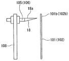
또한, 도 22 에 나타내는 안내 부재 (18) 와 같이, 상기와 같이 매달 때, 상측에 위치하는 능선이, 단자의 축선에 대략 평행하는 원추 형상으로 해도 된다. 이 경우에는, 용이하게 적층을 실시할 수 있음과 함께, 상기 매다는 것을 실시할 때의 정극판 (101) 및 부극판 (102) 의 위치 결정 정밀도를 더욱 향상시킬 수 있다.In addition, like the
이상, 본 발명의 실시형태에 대하여 도면을 참조하여 상세히 서술했지만, 구체적인 구성은 이 실시형태에 한정되지 않고, 본 발명의 요지를 일탈하지 않는 범위의 설계 변경 등도 포함된다.As mentioned above, although embodiment of this invention was described in detail with reference to drawings, a specific structure is not limited to this embodiment, The design change etc. of the range which do not deviate from the summary of this invention are included.
산업상 이용가능성Industrial availability
본 발명의 2 차 전지 제조 장치에 의하면, 정극판과 부극판의 크기가 상이한 2 차 전지여도, 양호한 정밀도로 위치 결정되어 적층된 2 차 전지를 제조할 수 있다.According to the secondary battery manufacturing apparatus of this invention, even if it is a secondary battery from which the magnitude | size of a positive electrode plate and a negative electrode plate differs, the secondary battery which has been positioned and laminated with good precision can be manufactured.
본 발명의 2 차 전지에 의하면, 정극 본체부와 정극판의 탭의 접속 부분 또는 부극 본체부와 부극판의 탭의 접속 부분에 있어서의 파단 등의 고장을 방지할 수 있다.According to the secondary battery of the present invention, failures such as breakage in the connecting portion of the tab of the positive electrode body portion and the positive electrode plate or the connecting portion of the tab of the negative electrode body portion and the negative electrode plate can be prevented.
1 : 2 차 전지 제조 장치
2 : 작업대
22a : 덮개체 고정부
3 : 전극판 반송 수단
4 : 덮개체 반송 수단
5 : 기립 수단
6 : 적층 고정 수단
8 : 수용 수단
9 : 안내 부재 착탈 수단 (안내 부재 제거 수단)
14 : 안내 부재
31c : 전극판 상하 위치 조정부 (정극판 배치부)
32c : 전극판 상하 위치 조정부 (부극판 배치부)
100 : 2 차 전지
101 : 정극판
101a : 본체부
101b, 101d : 탭
101c : 관통공
102 : 부극판
102a : 본체부
102b, 102c : 탭
102d, 102e : 관통공
103 : 전극체
104 : 케이스
105 : 정극 단자
106 : 부극 단자
107 : 케이스 본체
107a : 개구부
108 : 덮개체1: secondary battery manufacturing apparatus
2: work table
22a: cover body fixing part
3: electrode plate conveying means
4: cover body conveying means
5: standing means
6: laminated fixing means
8: accommodation means
9: guide member detachment means (guide member removal means)
14: guide member
31c: electrode plate up and down position adjustment part (positive electrode plate arrangement)
32c: Up and down position adjustment part of the electrode plate (negative electrode plate arrangement)
100: secondary battery
101: positive electrode plate
101a: main body
101b, 101d: tab
101c: through hole
102: negative electrode plate
102a: main body
102b, 102c: tab
102d, 102e: Through Hole
103: electrode body
104: case
105: positive electrode terminal
106: negative electrode terminal
107: case body
107a: opening
108: cover body
Claims (4)
상기 전극체를 수용하는 케이스와,
정극 단자 및 부극 단자가 형성되고, 상기 케이스에 끼워 맞추는 덮개를 갖고,
상기 정극판은, 대략 판상의 정극 본체부와, 상기 정극판의 중심선에 대해 선대칭으로 배치되고 또한 상기 정극 본체부로부터 상기 중심선을 따르는 돌출 방향으로 돌출되고 또한 상기 정극 본체부 및 상기 정극 단자에 접속된 제 1 탭을 구비하고,
상기 부극판은, 대략 판상의 부극 본체부와, 상기 부극판의 중심선에 대해 선대칭으로 배치되고 또한 상기 부극 본체부로부터 상기 돌출 방향으로 돌출되고 또한 상기 부극 본체부 및 상기 부극 단자에 접속된 제 2 탭을 구비하고,
상기 제 1 및 제 2 탭은 상기 적층되었을 때 서로 중첩되지 않는 위치에 배치되어 있는, 2 차 전지.An electrode body in which a positive electrode plate and a negative electrode plate are alternately laminated via a separator;
A case accommodating the electrode body;
A positive electrode terminal and a negative electrode terminal are formed, and have a lid fitted to the case,
The positive electrode plate is arranged in line symmetry with respect to the substantially plate-shaped positive electrode body portion and the center line of the positive electrode plate, and protrudes from the positive electrode body portion in the protruding direction along the center line and is connected to the positive electrode body portion and the positive electrode terminal. A first tab,
The said negative electrode plate is arranged in line symmetry with respect to the substantially plate-shaped negative electrode main body part and the centerline of the said negative electrode plate, and protrudes in the said projection direction from the said negative electrode main body part, and is connected to the said negative electrode main body part and the said negative electrode terminal With a tab,
And the first and second tabs are arranged in positions not overlapping each other when the stacked.
상기 덮개에 형성된 더미 단자를 추가로 갖고,
상기 제 2 탭은 접속용 탭과 더미 탭을 구비하고,
상기 접속용 탭이 상기 부극 단자에 접속됨과 함께 상기 더미 탭이 상기 더미 단자에 접속되어 있는, 2 차 전지.The method of claim 1,
Further having a dummy terminal formed in the cover,
The second tab has a connection tab and a dummy tab,
A secondary battery, wherein the connection tab is connected to the negative electrode terminal and the dummy tab is connected to the dummy terminal.
제 1 관통공이 형성된 탭을 구비한 정극판으로서 상기 탭은 상기 정극판의 중심선에 대해 선대칭으로 배치되어 있는 정극판을 상기 덮개 고정부에 반송하는 정극판 반송부와,
상기 반송된 정극판의 상기 제 1 관통공을 상기 정극 단자의 축부에 삽입하는 정극판 배치부와,
제 2 관통공이 형성된 탭을 구비한 부극판으로서 상기 탭은 상기 부극판의 중심선에 대해 선대칭으로 배치되어 있는 부극판을 상기 덮개 고정부에 반송하는 부극판 반송부와,
상기 반송된 부극판의 상기 제 2 관통공을 상기 부극 단자의 축부에 삽입하여 상기 정극판에 상기 부극판을 적층하는 부극판 배치부와,
상기 덮개 고정부에 의해 고정된 상기 덮개체를 기립시킴으로써 상기 적층된 상기 정극판 및 상기 부극판을 매달아 위치 결정하는 기립 수단을 갖는, 2 차 전지 제조 장치.A lid fixing part for fixing the lid formed with shaft portions of the positive electrode terminal and the negative electrode terminal, respectively, upward;
A positive electrode plate having a tab on which a first through hole is formed, the tab including a positive electrode plate conveying unit for conveying a positive electrode plate arranged in line symmetry with respect to a center line of the positive electrode plate to the cover fixing part;
A positive electrode plate placing portion for inserting the first through hole of the conveyed positive electrode plate into the shaft portion of the positive electrode terminal;
A negative electrode plate having a tab having a second through hole, the tab including a negative electrode plate conveying portion for conveying a negative electrode plate arranged in line symmetry with respect to a center line of the negative electrode plate to the lid fixing portion;
A negative electrode plate disposing portion for inserting the second through hole of the conveyed negative electrode plate into the shaft portion of the negative electrode terminal to stack the negative electrode plate on the positive electrode plate;
And a standing-up means for suspending and positioning the laminated positive electrode plate and the negative electrode plate by standing the cover body fixed by the lid fixing part.
상기 위치 결정된 상기 정극판과 상기 부극판을 서로 테이프로 고정시키는 적층 고정 수단과,
상기 테이프로 고정된 상기 정극판과 상기 부극판을 상기 덮개체와 끼워 맞추는 케이스에 수용하는 수용 수단을 추가로 갖는, 2 차 전지 제조 장치.The method of claim 3, wherein
Laminated fixing means for fixing the positioned positive electrode plate and the negative electrode plate to each other with tape;
The secondary battery manufacturing apparatus further includes the accommodating means which accommodates the said positive electrode plate and the said negative electrode plate fixed by the said tape in the case which fits with the said cover body.
Applications Claiming Priority (3)
| Application Number | Priority Date | Filing Date | Title |
|---|---|---|---|
| JP2010030421A JP5055394B2 (en) | 2010-02-15 | 2010-02-15 | Secondary battery and secondary battery manufacturing equipment |
| JPJP-P-2010-030421 | 2010-02-15 | ||
| PCT/JP2011/053126 WO2011099620A1 (en) | 2010-02-15 | 2011-02-15 | Secondary cell and secondary cell production device |
Publications (2)
| Publication Number | Publication Date |
|---|---|
| KR20120046292A true KR20120046292A (en) | 2012-05-09 |
| KR101332960B1 KR101332960B1 (en) | 2013-11-25 |
Family
ID=44367883
Family Applications (1)
| Application Number | Title | Priority Date | Filing Date |
|---|---|---|---|
| KR1020127004923A Expired - Fee Related KR101332960B1 (en) | 2010-02-15 | 2011-02-15 | Secondary cell and secondary cell production device |
Country Status (7)
| Country | Link |
|---|---|
| US (1) | US20120148913A1 (en) |
| EP (1) | EP2538483A1 (en) |
| JP (1) | JP5055394B2 (en) |
| KR (1) | KR101332960B1 (en) |
| CN (1) | CN203085688U (en) |
| TW (1) | TW201205917A (en) |
| WO (1) | WO2011099620A1 (en) |
Families Citing this family (28)
| Publication number | Priority date | Publication date | Assignee | Title |
|---|---|---|---|---|
| JP5796681B2 (en) * | 2012-06-28 | 2015-10-21 | 新神戸電機株式会社 | Secondary battery |
| WO2014013992A1 (en) * | 2012-07-17 | 2014-01-23 | 新神戸電機株式会社 | Secondary battery collector structure and secondary battery |
| KR101609425B1 (en) * | 2013-09-26 | 2016-04-05 | 주식회사 엘지화학 | Method of manufacturing electrode assembly using magazine |
| JP6191430B2 (en) * | 2013-12-09 | 2017-09-06 | 株式会社豊田自動織機 | Power storage device manufacturing apparatus and power storage device manufacturing method |
| JP6197630B2 (en) * | 2013-12-19 | 2017-09-20 | 株式会社豊田自動織機 | Manufacturing apparatus for adhering holding tape to electrode assembly and method for adhering holding tape to electrode assembly |
| WO2015112257A1 (en) * | 2014-01-27 | 2015-07-30 | The Penn State Research Foundation | Sandwich panels with battery cores |
| JP6330586B2 (en) * | 2014-09-03 | 2018-05-30 | 株式会社豊田自動織機 | Positioning structure |
| JP6413806B2 (en) * | 2015-01-30 | 2018-10-31 | 株式会社豊田自動織機 | Manufacturing method of power storage device and main alignment jig used in the manufacturing method |
| JP6464820B2 (en) * | 2015-02-27 | 2019-02-06 | 株式会社豊田自動織機 | Method for manufacturing power storage device |
| JP6627419B2 (en) * | 2015-10-28 | 2020-01-08 | 株式会社豊田自動織機 | Electrode lamination device |
| JP7075712B2 (en) * | 2016-03-18 | 2022-05-26 | 古河機械金属株式会社 | Electrode terminals for sheet-type lithium-ion batteries and sheet-type lithium-ion batteries |
| CN108140872B (en) * | 2016-07-12 | 2021-02-02 | 株式会社Lg化学 | Electrode assembly including electrode plate having bonded additional tab formed thereon |
| CN109690827A (en) | 2016-09-22 | 2019-04-26 | 苹果公司 | Current collector for stacked cell design |
| WO2018195372A1 (en) | 2017-04-21 | 2018-10-25 | Cougeller Research Llc | Battery cell with electrolyte diffusion material |
| US11888112B2 (en) | 2017-05-19 | 2024-01-30 | Apple Inc. | Rechargeable battery with anion conducting polymer |
| US11862801B1 (en) | 2017-09-14 | 2024-01-02 | Apple Inc. | Metallized current collector for stacked battery |
| US11335977B1 (en) | 2017-09-21 | 2022-05-17 | Apple Inc. | Inter-cell connection materials |
| KR102415121B1 (en) | 2017-09-22 | 2022-06-30 | 삼성에스디아이 주식회사 | Battery pack |
| US11043703B1 (en) | 2017-09-28 | 2021-06-22 | Apple Inc. | Stacked battery components and configurations |
| KR102278998B1 (en) * | 2017-12-26 | 2021-07-20 | 주식회사 엘지에너지솔루션 | Manufacturing system and manufacturing method of secondary battery |
| JP6994160B2 (en) * | 2018-04-16 | 2022-02-04 | トヨタ自動車株式会社 | Battery manufacturing method and battery manufacturing system |
| WO2019239560A1 (en) * | 2018-06-14 | 2019-12-19 | 国立大学法人東北大学 | Power storage element and storage battery using same |
| KR102814247B1 (en) * | 2019-10-01 | 2025-05-29 | 주식회사 엘지에너지솔루션 | Electrode Assembly for Secondary Battery Comprising Different-type Electrode |
| US11677120B2 (en) | 2020-09-08 | 2023-06-13 | Apple Inc. | Battery configurations having through-pack fasteners |
| US11600891B1 (en) | 2020-09-08 | 2023-03-07 | Apple Inc. | Battery configurations having balanced current collectors |
| US11588155B1 (en) | 2020-09-08 | 2023-02-21 | Apple Inc. | Battery configurations for cell balancing |
| US20240291117A1 (en) * | 2022-04-11 | 2024-08-29 | Lg Energy Solution, Ltd. | Prismatic secondary battery having improved safety |
| US20240128488A1 (en) * | 2022-10-17 | 2024-04-18 | Rivian Ip Holdings, Llc | Battery assembly systems and methods |
Family Cites Families (10)
| Publication number | Priority date | Publication date | Assignee | Title |
|---|---|---|---|---|
| JPS634551A (en) * | 1986-06-24 | 1988-01-09 | Matsushita Electric Ind Co Ltd | Lead-acid battery |
| JP3553755B2 (en) * | 1997-02-17 | 2004-08-11 | 三洋電機株式会社 | Prismatic storage battery |
| JP3749024B2 (en) * | 1998-09-28 | 2006-02-22 | 三洋電機株式会社 | battery |
| JP4850996B2 (en) * | 2000-04-28 | 2012-01-11 | パナソニック株式会社 | Electrode plate unit and battery |
| JP2002289168A (en) * | 2001-03-27 | 2002-10-04 | Shin Kobe Electric Mach Co Ltd | Control valve type lead storage battery |
| JP2003045498A (en) | 2001-08-02 | 2003-02-14 | Mitsubishi Heavy Ind Ltd | Secondary battery, its manufacturing method and its manufacturing apparatus |
| JP4615835B2 (en) * | 2003-07-29 | 2011-01-19 | パナソニック株式会社 | Battery manufacturing method |
| JP2006339054A (en) | 2005-06-03 | 2006-12-14 | Enerstruct Kk | Lithium secondary battery |
| JP5398192B2 (en) | 2008-07-29 | 2014-01-29 | 日本発條株式会社 | Stabilizer device and manufacturing method thereof |
| US8841020B2 (en) * | 2010-10-27 | 2014-09-23 | Medtronic, Inc. | Electrochemical cell with a direct connection between a feedthrough pin and an electrode stack |
-
2010
- 2010-02-15 JP JP2010030421A patent/JP5055394B2/en not_active Expired - Fee Related
-
2011
- 2011-02-15 US US13/391,550 patent/US20120148913A1/en not_active Abandoned
- 2011-02-15 CN CN2011900001466U patent/CN203085688U/en not_active Expired - Fee Related
- 2011-02-15 EP EP11742359A patent/EP2538483A1/en not_active Withdrawn
- 2011-02-15 KR KR1020127004923A patent/KR101332960B1/en not_active Expired - Fee Related
- 2011-02-15 WO PCT/JP2011/053126 patent/WO2011099620A1/en not_active Ceased
- 2011-02-15 TW TW100104973A patent/TW201205917A/en unknown
Also Published As
| Publication number | Publication date |
|---|---|
| CN203085688U (en) | 2013-07-24 |
| JP5055394B2 (en) | 2012-10-24 |
| TW201205917A (en) | 2012-02-01 |
| JP2011165620A (en) | 2011-08-25 |
| WO2011099620A1 (en) | 2011-08-18 |
| EP2538483A1 (en) | 2012-12-26 |
| US20120148913A1 (en) | 2012-06-14 |
| KR101332960B1 (en) | 2013-11-25 |
Similar Documents
| Publication | Publication Date | Title |
|---|---|---|
| KR101332960B1 (en) | Secondary cell and secondary cell production device | |
| EP3709431B1 (en) | Secondary battery charging/discharging device | |
| EP2535966A1 (en) | Secondary cell, and production device and production method for secondary cell | |
| EP3367470A1 (en) | Battery pack and method for producing battery pack | |
| EP2583787B1 (en) | Workpiece-positioning device and workpiece manufacturing method | |
| EP4604235A1 (en) | Insulating boot mounting system and usage method therefor, and battery pack production method | |
| JP2010113997A (en) | Stacking method and stacking device of cell of fuel cell | |
| JP2019009055A (en) | Battery module manufacturing equipment | |
| KR20180113291A (en) | Multi-cell tab cutting apparatus and method | |
| JP6675270B2 (en) | Component delivery device and wire harness manufacturing device including the same | |
| JP2016022539A (en) | Laminate cover mounting device | |
| JP7563294B2 (en) | Rotor Manufacturing Equipment | |
| CN217412962U (en) | Positioning mechanism and welding positioning device | |
| CN216720031U (en) | Lamination device and lithium battery production equipment | |
| JP2017103159A (en) | Assembly jig and assembly method | |
| JP2011217488A (en) | Manufacturing method for stator using split core, and stator manufacturing apparatus | |
| KR102895437B1 (en) | Battery module | |
| CN218311594U (en) | Welding equipment | |
| EP4057408A2 (en) | Apparatus for manufacturing battery cell | |
| CN216411634U (en) | Optical fiber cutting device | |
| WO2024117403A1 (en) | Laminated core manufacturing apparatus and laminated core manufacturing method | |
| CN218311951U (en) | Punching mechanism and welding equipment | |
| JP6713894B2 (en) | Transfer device and transfer method | |
| JP3432440B2 (en) | Harness mounting device and mounting method | |
| CN218559665U (en) | Circuit board placing frame |
Legal Events
| Date | Code | Title | Description |
|---|---|---|---|
| A201 | Request for examination | ||
| P11-X000 | Amendment of application requested |
St.27 status event code: A-2-2-P10-P11-nap-X000 |
|
| P13-X000 | Application amended |
St.27 status event code: A-2-2-P10-P13-nap-X000 |
|
| PA0105 | International application |
St.27 status event code: A-0-1-A10-A15-nap-PA0105 |
|
| PA0201 | Request for examination |
St.27 status event code: A-1-2-D10-D11-exm-PA0201 |
|
| PG1501 | Laying open of application |
St.27 status event code: A-1-1-Q10-Q12-nap-PG1501 |
|
| E902 | Notification of reason for refusal | ||
| PE0902 | Notice of grounds for rejection |
St.27 status event code: A-1-2-D10-D21-exm-PE0902 |
|
| E13-X000 | Pre-grant limitation requested |
St.27 status event code: A-2-3-E10-E13-lim-X000 |
|
| P11-X000 | Amendment of application requested |
St.27 status event code: A-2-2-P10-P11-nap-X000 |
|
| P13-X000 | Application amended |
St.27 status event code: A-2-2-P10-P13-nap-X000 |
|
| E701 | Decision to grant or registration of patent right | ||
| PE0701 | Decision of registration |
St.27 status event code: A-1-2-D10-D22-exm-PE0701 |
|
| GRNT | Written decision to grant | ||
| PR0701 | Registration of establishment |
St.27 status event code: A-2-4-F10-F11-exm-PR0701 |
|
| PR1002 | Payment of registration fee |
St.27 status event code: A-2-2-U10-U12-oth-PR1002 Fee payment year number: 1 |
|
| PG1601 | Publication of registration |
St.27 status event code: A-4-4-Q10-Q13-nap-PG1601 |
|
| PN2301 | Change of applicant |
St.27 status event code: A-5-5-R10-R11-asn-PN2301 |
|
| PN2301 | Change of applicant |
St.27 status event code: A-5-5-R10-R14-asn-PN2301 |
|
| LAPS | Lapse due to unpaid annual fee | ||
| PC1903 | Unpaid annual fee |
St.27 status event code: A-4-4-U10-U13-oth-PC1903 Not in force date: 20161120 Payment event data comment text: Termination Category : DEFAULT_OF_REGISTRATION_FEE |
|
| PC1903 | Unpaid annual fee |
St.27 status event code: N-4-6-H10-H13-oth-PC1903 Ip right cessation event data comment text: Termination Category : DEFAULT_OF_REGISTRATION_FEE Not in force date: 20161120 |
|
| R18-X000 | Changes to party contact information recorded |
St.27 status event code: A-5-5-R10-R18-oth-X000 |
|
| P22-X000 | Classification modified |
St.27 status event code: A-4-4-P10-P22-nap-X000 |
|
| P22-X000 | Classification modified |
St.27 status event code: A-4-4-P10-P22-nap-X000 |