JP2017103159A - Assembly jig and assembly method - Google Patents
Assembly jig and assembly method Download PDFInfo
- Publication number
- JP2017103159A JP2017103159A JP2015236817A JP2015236817A JP2017103159A JP 2017103159 A JP2017103159 A JP 2017103159A JP 2015236817 A JP2015236817 A JP 2015236817A JP 2015236817 A JP2015236817 A JP 2015236817A JP 2017103159 A JP2017103159 A JP 2017103159A
- Authority
- JP
- Japan
- Prior art keywords
- wall
- heat transfer
- side wall
- transfer plate
- main surface
- Prior art date
- Legal status (The legal status is an assumption and is not a legal conclusion. Google has not performed a legal analysis and makes no representation as to the accuracy of the status listed.)
- Withdrawn
Links
- 238000000034 method Methods 0.000 title claims abstract description 46
- NJPPVKZQTLUDBO-UHFFFAOYSA-N novaluron Chemical compound C1=C(Cl)C(OC(F)(F)C(OC(F)(F)F)F)=CC=C1NC(=O)NC(=O)C1=C(F)C=CC=C1F NJPPVKZQTLUDBO-UHFFFAOYSA-N 0.000 claims abstract description 11
- 238000001179 sorption measurement Methods 0.000 claims description 16
- 230000010354 integration Effects 0.000 claims description 5
- 238000002360 preparation method Methods 0.000 claims description 3
- 238000003825 pressing Methods 0.000 description 17
- 230000000452 restraining effect Effects 0.000 description 14
- 238000004519 manufacturing process Methods 0.000 description 11
- 239000000446 fuel Substances 0.000 description 9
- 238000010030 laminating Methods 0.000 description 4
- 230000007246 mechanism Effects 0.000 description 3
- 230000001070 adhesive effect Effects 0.000 description 2
- 238000006073 displacement reaction Methods 0.000 description 2
- 238000003780 insertion Methods 0.000 description 2
- 230000037431 insertion Effects 0.000 description 2
- 238000003475 lamination Methods 0.000 description 2
- HBBGRARXTFLTSG-UHFFFAOYSA-N Lithium ion Chemical compound [Li+] HBBGRARXTFLTSG-UHFFFAOYSA-N 0.000 description 1
- 239000000853 adhesive Substances 0.000 description 1
- 230000007248 cellular mechanism Effects 0.000 description 1
- 238000010586 diagram Methods 0.000 description 1
- 230000017525 heat dissipation Effects 0.000 description 1
- 229910001416 lithium ion Inorganic materials 0.000 description 1
- 239000000463 material Substances 0.000 description 1
- 229910052751 metal Inorganic materials 0.000 description 1
- 239000002184 metal Substances 0.000 description 1
- 239000011255 nonaqueous electrolyte Substances 0.000 description 1
Images


Classifications
-
- Y—GENERAL TAGGING OF NEW TECHNOLOGICAL DEVELOPMENTS; GENERAL TAGGING OF CROSS-SECTIONAL TECHNOLOGIES SPANNING OVER SEVERAL SECTIONS OF THE IPC; TECHNICAL SUBJECTS COVERED BY FORMER USPC CROSS-REFERENCE ART COLLECTIONS [XRACs] AND DIGESTS
- Y02—TECHNOLOGIES OR APPLICATIONS FOR MITIGATION OR ADAPTATION AGAINST CLIMATE CHANGE
- Y02E—REDUCTION OF GREENHOUSE GAS [GHG] EMISSIONS, RELATED TO ENERGY GENERATION, TRANSMISSION OR DISTRIBUTION
- Y02E60/00—Enabling technologies; Technologies with a potential or indirect contribution to GHG emissions mitigation
- Y02E60/10—Energy storage using batteries
Landscapes
- Secondary Cells (AREA)
- Battery Mounting, Suspending (AREA)
Abstract
Description
本発明は、組付け治具、及び、組付け方法に関する。 The present invention relates to an assembly jig and an assembly method.
特許文献1には、燃料電池支持機構が記載されている。この燃料電池支持機構は、複数のセルを含む積層部品を積層してなる燃料電池スタックと、燃料電池スタックにおける積層部品の変位を拘束するための板状の外部拘束部材と、を備える。
特許文献1に記載された燃料電池支持機構においては、燃料電池スタックが外部からの荷重を受けると判定された場合、板状の外部拘束部材を燃料電池スタックの側面に接触させることにより、積層部品の積層方向に交差する方向への変位を一括して拘束する。これにより、積層部品の当該方向への位置ずれの抑制が図られる。
In the fuel cell support mechanism described in
ここで、上記の燃料電池スタックといった電池モジュールにおいては、隣り合うセルの間に板状の熱伝導部材を介在させることが考えられる。このような電池モジュールは、熱伝導部材の表面(伝熱面)を外部部品に接触させることにより、熱伝導部材を介して電池セルから外部部品への放熱を促すことができる。したがって、このような電池モジュールにおいては、複数の伝熱面を外部部品に確実に接触させるために、伝熱面同士の位置合わせが重要となる。 Here, in a battery module such as the fuel cell stack described above, it is conceivable to interpose a plate-like heat conducting member between adjacent cells. Such a battery module can promote heat dissipation from the battery cell to the external component via the heat conductive member by bringing the surface (heat transfer surface) of the heat conductive member into contact with the external component. Therefore, in such a battery module, it is important to align the heat transfer surfaces in order to reliably bring the plurality of heat transfer surfaces into contact with the external components.
しかしながら、セルや熱伝導部材等の積層部品には、公差の範囲において寸法にバラつきがある。したがって、特許文献1に記載の燃料電池機構のように、板状の拘束部材を用いて複数の積層部品(セル等)を一括して拘束した場合には、積層部品の寸法のバラつきに起因して、伝熱面同士を正確に位置合わせすることが困難である。これに対して、本発明者の知見によれば、電池モジュールの製造の際に、積層部品を個別に位置合わせの基準面に押し当てる等の手当てを行えば、積層部品の寸法のバラつきに依らずに伝熱面同士を正確に位置合わせすることが可能である。ただし、その場合には、積層部品を個別に押圧するために、大掛かりな装置が必要とも考えられる。
However, laminated parts such as cells and heat conducting members have variations in dimensions within a tolerance range. Therefore, as in the fuel cell mechanism described in
そこで、本発明は、大掛かりな装置を用いることなく伝熱面同士を正確に位置合わせすることを可能とする組付け治具、及び、組付け方法を提供することを目的とする。 Therefore, an object of the present invention is to provide an assembling jig and an assembling method capable of accurately aligning heat transfer surfaces without using a large-scale apparatus.
上記課題を解決するために、本発明に係る組付け治具は、電池セルと、互いに対向する第1の側壁及び第2の側壁を有し第1の側壁及び第2の側壁の間に電池セルを保持するセルホルダと、第1の側壁及び第2の側壁の間において電池セル上に配置される第1の部分と電池セル及び第2の側壁を介して第1の側壁に対向する第2の部分とを有する伝熱プレートと、を一体的に組み付けるための組付け治具であって、伝熱プレートとセルホルダとが配置される主面を有する台座と、主面に設けられた第1の壁部と、主面に設けられ第1の壁部に対向する第2の壁部と、を備え、第1の壁部は、主面に配置されたセルホルダの第1の側壁に対向する第1の側面を有し、第2の壁部は、主面に配置された伝熱プレートの第2の部分に対向する第2の側面を有し、第1の側面には、第1の側壁を第1の側面に吸着するための吸着孔の第1の開口部が設けられ、第2の側面には、第2の部分を第2の側面に吸着するための吸着孔の第2の開口部が設けられている。 In order to solve the above problems, an assembling jig according to the present invention has a battery cell, a first side wall and a second side wall facing each other, and a battery between the first side wall and the second side wall. A cell holder for holding the cell, a first portion disposed on the battery cell between the first side wall and the second side wall, and a second part facing the first side wall via the battery cell and the second side wall An assembly jig for integrally assembling the heat transfer plate, and a pedestal having a main surface on which the heat transfer plate and the cell holder are arranged, and a first provided on the main surface And a second wall provided on the main surface and facing the first wall, the first wall facing the first side wall of the cell holder disposed on the main surface The second wall portion has a first side surface, and the second wall portion faces the second portion of the heat transfer plate disposed on the main surface. The first side surface is provided with a first opening of an adsorption hole for adsorbing the first side wall to the first side surface, and the second side surface is provided with a second portion. A second opening of the suction hole for suctioning to the second side surface is provided.
この組付け治具は、セルホルダの第1の側壁に対向する第1の側面と、伝熱プレートの第2の部分に対向する第2の側面と、を備え、第1の側面には、吸着孔の第1の開口部が設けられ、第2の側面には、吸着孔の第2の開口部が設けられている。このため、セルホルダの第1の側壁を第1の側面に吸着することによって、第1の側面を基準としてセルホルダを確実に位置決めすることができる。また、伝熱プレートの第2の部分を第2の側面に吸着することによって、第2の側面を基準として伝熱プレートを確実に位置決めすることができる。つまり、セルホルダ及び伝熱プレートの寸法のバラつきに依らず、セルホルダの第1の側壁の外面と伝熱プレートの第2の部分の外面との間隔を、第1の側面と第2の側面との距離に応じて一定にすることができる。したがって、この組付け治具によって電池セルとセルホルダと伝熱プレートとを一体的に組み付けた電池ユニットを積層して電池モジュールを製造する際には、複数の電池ユニットを一括して位置合わせの基準面に押し当てれば、伝熱プレートの外面同士を正確に位置決めすることが可能となる。そして、この伝熱プレートの外面を伝熱面として用いればよい。以上のように、この組付け治具によれば、大掛かりな装置を用いることなく伝熱面同士を正確に位置合わせすることが可能となる。 The assembling jig includes a first side surface facing the first side wall of the cell holder and a second side surface facing the second portion of the heat transfer plate, and the first side surface has an adsorption A first opening of the hole is provided, and a second opening of the suction hole is provided on the second side surface. For this reason, by adsorbing the first side wall of the cell holder to the first side surface, the cell holder can be reliably positioned with reference to the first side surface. In addition, by adsorbing the second portion of the heat transfer plate to the second side surface, the heat transfer plate can be reliably positioned with reference to the second side surface. That is, regardless of variations in the dimensions of the cell holder and the heat transfer plate, the distance between the outer surface of the first side wall of the cell holder and the outer surface of the second portion of the heat transfer plate is determined between the first side surface and the second side surface. It can be made constant according to the distance. Therefore, when a battery module is manufactured by stacking battery units in which battery cells, cell holders, and heat transfer plates are integrally assembled using this assembly jig, a plurality of battery units are collectively aligned. If pressed against the surface, the outer surfaces of the heat transfer plates can be accurately positioned. And what is necessary is just to use the outer surface of this heat-transfer plate as a heat-transfer surface. As described above, according to this assembly jig, it is possible to accurately align the heat transfer surfaces without using a large-scale apparatus.
本発明に係る組付け治具においては、主面には、第1の部分が配置される第1の凹部が設けられていてもよい。この場合、第1の凹部の内面を用いて伝熱プレートの位置決めが可能となる。 In the assembling jig according to the present invention, the main surface may be provided with a first recess in which the first portion is disposed. In this case, the heat transfer plate can be positioned using the inner surface of the first recess.
本発明に係る組付け治具においては、第2の側面には、主面に配置された伝熱プレートの第2の部分に対向する底面を有し、第2の部分が配置される第2の凹部が設けられており、第2の開口部は、底面に設けられていてもよい。この場合、伝熱プレートの第2の部分を第2の凹部内に進入させることによって、伝熱プレートの第2の部分がセルホルダの第2の側壁から離間するように伝熱プレート及びセルホルダを主面上に配置することができる。 In the assembly jig according to the present invention, the second side surface has a bottom surface facing the second portion of the heat transfer plate disposed on the main surface, and the second portion is disposed on the second side surface. The recess may be provided, and the second opening may be provided on the bottom surface. In this case, the heat transfer plate and the cell holder are mainly moved so that the second portion of the heat transfer plate is separated from the second side wall of the cell holder by causing the second portion of the heat transfer plate to enter the second recess. Can be placed on the surface.
本発明に係る組付け治具においては、第1の側面には、複数の第1の開口部が設けられていてもよい。この場合、複数の第1の開口部を用いて、セルホルダの第1の側壁を第1の側面に平行にしながら第1の側面に吸着することができる。 In the assembly jig according to the present invention, a plurality of first openings may be provided on the first side surface. In this case, the first side wall of the cell holder can be adsorbed to the first side surface while being parallel to the first side surface using the plurality of first openings.
本発明に係る組付け治具においては、第1の壁部は、長尺状であり、第1の開口部は、第1の壁部の長手方向に沿って配列されていてもよい。この場合、第1の壁部の長手方向に沿って、セルホルダの第1の側壁を第1の側面に平行にしながら第1の側面に吸着することができる。 In the assembly jig according to the present invention, the first wall portion may be long, and the first opening may be arranged along the longitudinal direction of the first wall portion. In this case, the first side wall of the cell holder can be adsorbed to the first side surface in parallel with the first side surface along the longitudinal direction of the first wall portion.
本発明に係る組付け治具においては、第2の側面には、複数の第2の開口部が設けられていてもよい。この場合、複数の第2の開口部間を用いて、伝熱プレートの第2の部分を第2の側面に平行にしながら第2の側面に吸着することができる。 In the assembly jig according to the present invention, a plurality of second openings may be provided on the second side surface. In this case, the second portion of the heat transfer plate can be adsorbed to the second side surface while being parallel to the second side surface using the space between the plurality of second openings.
本発明に係る組付け治具においては、第2の壁部は、長尺状であり、第2の開口部は、第2の壁部の長手方向に沿って配列されていてもよい。この場合、第2の壁部の長手方向に沿って、伝熱プレートの第2の部分を第2の側面に平行にしながら第2の側面に吸着することができる。 In the assembly jig according to the present invention, the second wall portion may be long, and the second opening may be arranged along the longitudinal direction of the second wall portion. In this case, the second portion of the heat transfer plate can be adsorbed to the second side surface in parallel with the second side surface along the longitudinal direction of the second wall portion.
本発明に係る組付け方法は、電池セルと、互いに対向する第1の側壁及び第2の側壁を有し第1の側壁及び前記第2の側壁の間に電池セルを保持するセルホルダと、第1の側壁及び第2の側壁の間において電池セル上に配置される第1の部分と電池セル及び第2の側壁を介して第1の側壁に対向する第2の部分とを有する伝熱プレートと、を一体的に組み付ける組付け方法であって、主面を有する台座と、主面に設けられ第1の側面を有する第1の壁部と、主面に設けられ第1の側面に対向する第2の側面を有する第2の壁部と、を備える組付け治具を用意する用意工程と、第1の部分が主面側に位置し、且つ、第2の部分が第2の側面側に位置するように、伝熱プレートを主面に配置するプレート配置工程と、プレート配置工程の後に、第1の側壁が第1の側面側に位置し、且つ、第2の側面及び第2の部分側に第2の側壁が位置するように、セルホルダを主面に配置するホルダ配置工程と、ホルダ配置工程の後に、第1の側壁と第2の側壁との間において第1の部分上に電池セルを配置し、電池セルとセルホルダと伝熱プレートとを互いに一体化する一体化工程と、を備え、第1の側面には、第1の側壁を第1の側面に吸着するための吸着孔の第1の開口部が設けられており、第2の側面には、第2の部分を第2の側面に吸着するための吸着孔の第2の開口部が設けられており、プレート配置工程は、伝熱プレートを主面に配置した後に、第2の開口部を介して第2の部分を第2の側面に吸着するプレート吸着工程を有し、ホルダ配置工程は、セルホルダを主面に配置した後に、第1の開口部を介して第1の側壁を第1の側面に吸着するホルダ吸着工程を有する。 An assembling method according to the present invention includes a battery cell, a cell holder having a first side wall and a second side wall facing each other, and holding the battery cell between the first side wall and the second side wall, A heat transfer plate having a first part disposed on the battery cell between the one side wall and the second side wall and a second part facing the first side wall through the battery cell and the second side wall And a pedestal having a main surface, a first wall portion provided on the main surface and having a first side surface, and provided on the main surface and opposed to the first side surface. A preparing step of preparing an assembly jig comprising a second wall portion having a second side surface, a first portion located on a main surface side, and a second portion being a second side surface After the plate placement step of placing the heat transfer plate on the main surface so as to be located on the side, and the plate placement step, A holder arranging step of arranging the cell holder on the main surface such that the side wall of the cell holder is located on the first side surface side and the second side wall is located on the second side surface and the second portion side. After, the battery cell is disposed on the first portion between the first side wall and the second side wall, and the battery cell, the cell holder, and the heat transfer plate are integrated with each other, and The first side surface is provided with a first opening of an adsorption hole for adsorbing the first side wall to the first side surface, and the second side is provided with the second portion on the second side surface. A second opening of the suction hole for adsorbing to the side surface is provided, and the plate placement step includes placing the heat transfer plate on the main surface, and then placing the second part through the second opening. 2 has a plate adsorption process that adsorbs to the side surface, and the holder arrangement process is performed after the cell holder is arranged on the main surface. Having a holder adsorption step of adsorbing a first sidewall through the first opening in the first side surface.
この組付け方法では、プレート配置工程において、組付け治具の主面に配置した伝熱プレートの第2の部分を第2の側面に吸着する。このため、伝熱プレートの第2の部分を第2の側面に吸着することによって、第2の側面を基準として伝熱プレートを確実に位置決めすることができる。また、ホルダ配置工程において、組付け治具の主面に配置したセルホルダの第1の側壁を第1の側面に吸着する。このため、セルホルダの第1の側壁を第1の側面に吸着することによって、第1の側面を基準としてセルホルダを確実に位置決めすることができる。つまり、セルホルダ及び伝熱プレートの寸法のバラつきに依らず、セルホルダの第1の側壁の外面と伝熱プレートの第2の部分の外面との間隔を、第1の側面と第2の側面との距離に応じて一定にすることができる。したがって、この組付け方法によって電池セルとセルホルダと伝熱プレートとを一体的に組み付けた電池ユニットを積層して電池モジュールを製造する際には、複数の電池ユニットを一括して位置合わせの基準面に押し当てれば、伝熱プレートの外面同士を正確に位置決めすることが可能となる。そして、この伝熱プレートの外面同士を伝熱面として用いればよい。以上のように、この組付け方法によれば、大掛かりな装置を用いることなく伝熱面同士を正確に位置合わせすることが可能となる。 In this assembling method, the second part of the heat transfer plate arranged on the main surface of the assembling jig is adsorbed to the second side surface in the plate arranging step. For this reason, by adsorbing the second portion of the heat transfer plate to the second side surface, the heat transfer plate can be reliably positioned with reference to the second side surface. Further, in the holder arranging step, the first side wall of the cell holder arranged on the main surface of the assembly jig is adsorbed on the first side surface. For this reason, by adsorbing the first side wall of the cell holder to the first side surface, the cell holder can be reliably positioned with reference to the first side surface. That is, regardless of variations in the dimensions of the cell holder and the heat transfer plate, the distance between the outer surface of the first side wall of the cell holder and the outer surface of the second portion of the heat transfer plate is determined between the first side surface and the second side surface. It can be made constant according to the distance. Therefore, when a battery module is manufactured by stacking battery units in which battery cells, cell holders, and heat transfer plates are integrally assembled by this assembling method, a plurality of battery units are collectively aligned as a reference plane. If it presses against, it becomes possible to position the outer surfaces of a heat-transfer plate correctly. And what is necessary is just to use the outer surfaces of this heat-transfer plate as a heat-transfer surface. As described above, according to this assembly method, it is possible to accurately align the heat transfer surfaces without using a large-scale apparatus.
本発明によれば、大掛かりな装置を用いることなく伝熱面同士を正確に位置合わせすることを可能とする組付け治具、及び、組付け方法を提供することができる。 According to the present invention, it is possible to provide an assembling jig and an assembling method capable of accurately aligning heat transfer surfaces without using a large-scale apparatus.
以下、本発明に係る組付け治具、及び、組付け方法の一実施形態について、図面を参照して詳細に説明する。なお、図面の説明において、同一の要素同士、或いは相当する要素同士には、同一の符号を付し、重複する説明を省略する場合がある。 DESCRIPTION OF EMBODIMENTS Hereinafter, an embodiment of an assembly jig and an assembly method according to the present invention will be described in detail with reference to the drawings. In the description of the drawings, the same elements or corresponding elements may be denoted by the same reference numerals, and redundant description may be omitted.
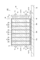
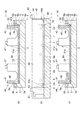
図1は、電池モジュールの模式的な断面図である。図1に示されるように、電池モジュール50は、互いに積層された複数(例えば7個)の電池ユニット10を含む積層体60を備える。電池ユニット10は、それぞれ、電池セル20と、伝熱プレート30と、セルホルダ40と、を有する。電池セル20は、セルホルダ40に保持されている。伝熱プレート30は、互いに隣り合う電池セル20の間に介在されている。
FIG. 1 is a schematic cross-sectional view of a battery module. As shown in FIG. 1, the
電池モジュール50は、積層体60を外部部品に固定するための一対の固定部材70を備えている。外部部品は、ここでは、電池パック100の筐体90である。固定部材70は、電池ユニット10の積層方向(以下、単に「積層方向」という場合がある)における積層体60の両端に配置されている。固定部材70は、積層方向に交差する方向に沿って延びる拘束部72と、積層方向に沿って拘束部72から延設された固定部73と、を含む。拘束部72及び固定部73は、例えば矩形板状である。固定部材70は、拘束部72と固定部73とによって、例えばL字板状に形成されている。
The
拘束部72は、電池セル20に拘束荷重を付加するために用いられる。より具体的には、積層方向における積層体60の両端に配置された一対の拘束部72を、拘束ボルト74及びナット75により互いに締結することによって、積層方向に沿って電池セル20に拘束力が加えられている。
The restraining
固定部73は、積層体60を筐体90に固定するために用いられる。より具体的には、積層体60は、固定部73の底面を筐体90に接触させた状態において、固定部73をボルト76によって締結することにより、筐体90に固定されている。積層体60と筐体90との間には、熱伝導部材(TIM:Thermal Interface Material)80が介在している。熱伝導部材80は、積層体60及び筐体90に密着している。
The fixing
なお、積層方向における積層体60の一端を構成する電池ユニット10と固定部材70との間には、ミドルプレート77が配置されている。また、ミドルプレート77と固定部材70との間には、電池セル20が膨張したときに圧縮される弾性部材78が介在されている。
A
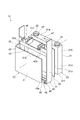
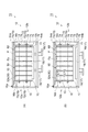
続いて、電池ユニット10の各部について説明する。図2は、図1に示された電池ユニットの分解斜視図である。電池セル20は、例えばリチウムイオン二次電池等の非水電解質二次電池である。電池セル20は、電極組立体(不図示)と、電極組立体を収容する矩形箱状のケース21と、電極組立体の電極(正極及び負極のそれぞれ)に電気的に接続され、ケース21から突出する一対の電極端子22と、を有している。電極組立体は、複数の正極及び負極と、正極と負極との間に配置されたセパレータと、を含む。正極及び負極は、セパレータを介して交互に積層されている。一例として、正極及び負極の積層方向は、電池セル20(電池ユニット10)の積層方向と略一致している。
Next, each part of the
ケース21は、直方体状を呈している。ケース21は、互いに平行な一対の側面21a,21bと、互いに平行な一対の側面21c,21dと、互いに平行な上面21e及び底面21fと、を含む。側面21a,21bは、積層方向に交差する面である。側面21c,21dは、積層方向に沿った面であり、側面21aと側面21bとを接続する面である。側面21a,21bは、側面21c,21dに隣接する別の側面である。電極端子22は、上面21eに設けられる。
The
伝熱プレート30は、例えば、金属により形成されている。伝熱プレート30は、例えば長方形板状の第1の部分31と、例えば長方形板状の第2の部分32と、を有している。この例では、第1の部分31と第2の部分32とは、互いに交差(例えば直交)している。第2の部分32は、第1の部分の一端から延設されている。第2の部分32は、長尺状である。
The
伝熱プレート30は、第1の部分31がケース21の側面21a上に位置し、且つ、第2の部分32が側面21c上に位置するように、電池セル20のケース21に取り付けられている。すなわち、伝熱プレート30は、電池セル20の側面21a、及び側面21aに隣接する別の側面21cにわたって延在している。第1の部分31と側面21aとの間には、絶縁性及び接着性を有するフィルム55が介在されている。フィルム55は、例えば絶縁性の両面テープである。
The
第1の部分31は、フィルム55を介して、側面21a上において電池セル20に熱的に接続されている。一方、第2の部分32は、筐体90に熱的に接続される。より具体的には、第2の部分32は、側面21cと反対側の表面が筐体90上の熱伝導部材80に接触することにより、熱伝導部材80を介して筐体90に熱的に接続される。これにより、伝熱プレート30は、電池セル20と筐体90とを熱的に接続する。以下では、第2の部分32における側面21cと反対側の表面を伝熱面32sと称する。
The
セルホルダ40は、互いに対向する側壁(第1の側壁)41及び側壁(第2の側壁)42と、側壁41,42のそれぞれに連続する上部壁43及び底壁44と、を有している。セルホルダ40においては、側壁41,42と上部壁43及び底壁44とによって、電池セル20が嵌め合される直方体状の空間部が規定されている。側壁41,42は、それぞれ、当該空間部に電池セル20が嵌め合されたときにケース21の側面21c,21d上に配置される。
The
すなわち、セルホルダ40は、側壁41と側壁42との間に電池セル20を保持する。したがって、伝熱プレート30の第1の部分31は、側壁41及び側壁42の間において電池セル20上に配置される。上部壁43は、ケース21の側面21a上に配置される。底壁44は、ケース21の底面21f上に配置される。伝熱プレート30の第2の部分32は、セルホルダ40の側壁42を介してケース21の側面21c上に配置される。すなわち、伝熱プレート30の第2の部分32は、側壁42及び電池セル20を介して側壁41に対向する。
That is, the
側壁41は、長尺状(例えば長方形板状)に形成されている。側壁41は、長手方向の一端側において底壁44に連続すると共に、長手方向の他端側、且つ、短手方向の一端側において上部壁43に連続している。側壁42は、長尺状(例えば長方形板状)に形成されている。側壁42は、長手方向の一端側において底壁44に連続すると共に、長手方向の他端側、且つ、短手方向の一端側において上部壁43に連続している。側壁41と側壁42との間には、それぞれの一端同士を接続するように底壁44に沿って延びる支持壁45が設けられている(以下、図3を併せて参照)。セルホルダ40に保持された電池セル20は、この支持壁45の内面45s及び上部壁43の内面43sに当接することにより支持される。
The
側壁42の短手方向における側壁42の幅は、側壁42の長手方向における一端部及び他端部よりも、一端部と他端部との間の部分において相対的に小さくされている。すなわち、側壁42の短手方向における側端面には、凹部42aが設けられている。伝熱プレート30の第1の部分31は、その内面31aにおいて凹部42aの底面に当接する。このとき、第1の部分31の内面31aは、支持壁45と上部壁43との間においてセルホルダ40内に露出する。
The width of the
すなわち、側壁42の長手方向における凹部42aの長さは、この例では、第2の部分32の長手方向における第1の部分31の長さと同程度以上である。また、このとき、第1の部分31の内面31aは、上部壁43の内面43s及び支持壁45の内面45sと略面一となる。このため、セルホルダ40に保持された電池セル20は、フィルム55を介して、上部壁43の内面43s、支持壁45の内面45s、及び、伝熱プレート30の第1の部分31の内面31aに接触する。すなわち、一例として、凹部42aの深さは、第1の部分31の厚さよりも小さくなっている。
That is, the length of the
また、側壁42の側壁41と反対側の面(外面)には、伝熱プレート30の第2の部分32が配置される凹部42bが設けられている。側壁42の長手方向における凹部42bの長さは、この例では、第2の部分32の長手方向における第2の部分32の長さと同程度となっている。凹部42bの深さは、例えば第2の部分32の厚さよりも小さくなっている。
Further, a
上部壁43は、例えば長方形板状に形成されている。上部壁43と側壁41,42とは、例えば直交している。上部壁43には、電池セル20の電極端子22が収容される2つの端子収容部46が設けられている。また、上部壁43には、端子収容部46に連続する2つの柱部47が設けられている。各柱部47には、拘束ボルト74が挿通される挿通孔が設けられている。
The
底壁44は、例えば長方形板状に形成されている。底壁44の短手方向と側壁41,42の短手方向とは、一致している。底壁44の長手方向における一端側及び他端側のそれぞれには、突出部48が設けられている。各突出部48には、拘束ボルト74が挿通される挿通孔が設けられている。
The
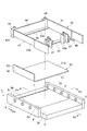
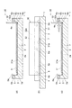
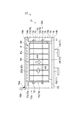
本実施形態に係る組付け治具、及び、組付け方法は、以上のような電池セル20と伝熱プレート30とセルホルダ40とを一体的に組み付けて電池ユニット10を作製するためのものである。引き続いて、本実施形態に係る組付け治具について説明する。図3は、セルホルダ、伝熱プレート、及び組付け治具の模式的な斜視図である。図4の(a),(b)は、本実施形態に係る組付け治具の模式的な断面図である。図4の(a)は、図3のIVa−IVa線に沿った断面であり、図4の(b)は、図3のIVb−IVb線に沿った断面である。図3,4に示されるように、組付け治具1は、台座2と、台座2に設けられた長尺状の壁部(第1の壁部)3と、台座2に設けられ壁部3に対向する長尺状の壁部(第2の壁部)4と、を備えている。
The assembling jig and the assembling method according to the present embodiment are for producing the
台座2は、例えば矩形板状に形成されている。台座2は、伝熱プレート30とセルホルダ40とが配置される主面2aを有している。主面2aには、伝熱プレート30の第1の部分31が配置される凹部(第1の凹部)7が設けられている。壁部3,4の長手方向における凹部7の長さD2は、伝熱プレート30の第2の部分32の長手方向における第1の部分31の長さと同程度になっている。凹部7の深さD3は、第1の部分31の厚さT1よりもセルホルダ40の上部壁43及び支持壁45の厚さT2分、小さくなっている。すなわち、第1の部分31の厚さT1は、凹部7の深さD3と上部壁43の厚さT2とを合わせた大きさと同程度になっている。
The
壁部3は、台座2の主面2aに設けられている。壁部3は、長尺状(例えば長方形板状)に形成されている。壁部3の長手方向の寸法は、セルホルダ40の側壁41の長手方向の寸法に対応している。壁部3は、短手方向の一端側において台座2に連続している。壁部3は、主面2aに配置されたセルホルダ40の側壁41に対向する側面(第1の側面)3aを有している。側面3aには、主面2aに配置されたセルホルダ40の側壁41を側面3aに吸着するための吸着孔5の複数(例えば5個)の開口部(第1の開口部)5aが設けられている。開口部5aは、壁部3の長手方向に沿って、例えば等間隔で配列されている。吸着孔5は、壁部3において側面3aの開口部5aから側面3aの裏側の開口部5bに亘って延び、壁部3を貫通している。開口部5a,5bの形状は、例えば円形である。開口部5bには、吸着孔5内を真空引きするためのポンプが接続される。
The
壁部4は、台座2の主面2aに設けられている。壁部4は、長尺状(例えば長方形板状)に形成されている。壁部4の長手方向の寸法は、伝熱プレート30の第2の部分32の長手方向の寸法に対応している。このため、壁部3の長手方向の寸法は、壁部4の長手方向の寸法よりも大きい。壁部4は、短手方向の一端側において台座2に連続している。壁部4は、主面2aに配置された伝熱プレート30の第2の部分32に対向する側面(第2の側面)4aを有している。側面3a及び側面4aは、例えば、主面2aと略垂直となっており、互いに略平行となっている。側面3a及び側面4aは、主面2aに交差する方向からみて、凹部7を挟んで互いに対向している。側面3aと側面4aとの距離D1は、組付け後の電池ユニット10における、セルホルダ40の側壁41の外面と伝熱プレート30の第2の部分32の外面(伝熱面32a)との間隔を規定する。
The
側面4aには、伝熱プレート30の第2の部分32が配置される底面8aを有する凹部(第2の凹部)8が設けられている。底面8aは、主面2aに配置された伝熱プレート30の第2の部分32に対向している。壁部3,4の長手方向における凹部8の長さD2は、伝熱プレート30の第2の部分32の長手方向における第2の部分32の長さと同程度になっている。側面4aには、主面2aに配置された伝熱プレート30の第2の部分32を側面4aに吸着するための吸着孔6の複数(例えば3個)の開口部(第2の開口部)6aが設けられている。ここでは、開口部6aは、凹部8の底面8aに設けられている。開口部6aは、壁部4の長手方向に沿って、例えば等間隔で配列されている。吸着孔6は、壁部4において凹部8の底面8aの開口部6aから側面4aの裏側の開口部6bに亘って延び、壁部4を貫通している。開口部6a,6bの形状は、例えば円形である。開口部6bには、吸着孔6内を真空引きするためのポンプが接続される。なお、開口部5aの数は、開口部6aの数よりも多い。
The
引き続いて、以上のように構成される組付け治具1を用いた組付け方法の一例について説明する。まず、この組付け方法の概略について説明する。この組付け方法においては、まず、組付け治具1を用意する(用意工程)。続いて、組付け治具1の台座2に伝熱プレート30を配置する(プレート配置工程)。その後に、組付け治具1の台座2にセルホルダ40を配置する(ホルダ配置工程)。その後に、セルホルダ40の側壁41,42間、且つ、伝熱プレート30上に電池セル20を配置し、電池セル20と伝熱プレート30とセルホルダ40とを一体化する(一体化工程)。
Subsequently, an example of an assembly method using the
以下、各工程について詳細に説明する。図5〜7は、本実施形態に係る組付け方法の主要な工程を示す図である。まずプレート配置工程について説明する。図5の(a),(b)に示されるように、組付け治具1の台座2に、伝熱プレート30を配置する。具体的には、主面2a側に第1の部分31が位置し、且つ、側面4a側に伝熱プレート30の第2の部分32が位置するように、伝熱プレート30を主面2aに配置する。このとき、第1の部分31が凹部7に配置されるようにする。伝熱プレート30の第1の部分31の厚さT1は、凹部7の深さD3よりも大きい。このため、第1の部分31は、主面2aから突出する。一方、このとき、第2の部分32を側面4aに当接させる。ここでは、第2の部分32を、凹部8内に配置しつつ底面8aに当接するようにする。
Hereinafter, each step will be described in detail. 5-7 is a figure which shows the main processes of the assembly | attachment method which concerns on this embodiment. First, the plate placement process will be described. As shown in FIGS. 5A and 5B, the
その状態において、開口部6aを介して第2の部分32を側面4aに吸着する(プレート吸着工程)。より具体的には、この工程では、吸着孔6に接続されているポンプを駆動することにより、図5の(c)に示されるように、伝熱プレート30に対して吸着力A1が作用する。この吸着力A1によって、伝熱プレート30の第2の部分32が壁部4の側面4aに吸着される。これにより、伝熱プレート30が、組付け治具1の側面4a(凹部8の底面8a)を基準として確実に位置決めされる。
In this state, the
次に、ホルダ配置工程について説明する。図6の(a),(b)に示されるように、この工程においては、プレート配置工程の後に、伝熱プレート30が配置された組付け治具1の台座2に、セルホルダ40を配置する。具体的には、側面3a側に側壁41が位置し、且つ、側面4a及び第2の部分32側に側壁42が位置するように、セルホルダ40を主面2aに配置する。このとき、上部壁43と支持壁45とが、凹部7を規定する主面2aの平面部に載置されるようにする。換言すれば、上部壁43と支持壁45とが、主面2aに交差する方向からみて凹部7に重複しないようにする。これにより、先の工程により凹部7に配置されている伝熱プレート30の第1の部分31の内面31aが、支持壁45と上部壁43との間においてセルホルダ40内に露出する。ここで、第1の部分31の厚さT1は、凹部7の深さD3と上部壁43及び支持壁45の厚さT2とを合わせた大きさと同程度になっている。このため、第1の部分31の内面31aと、上部壁43の内面43s及び支持壁45の内面45sとが略面一となる。
Next, a holder arrangement process will be described. As shown in FIGS. 6A and 6B, in this step, the
そして、側壁41を側面3aに当接させる。その状態において、開口部5aを介して側壁41を側面3aに吸着する(ホルダ吸着工程)。より具体的には、この工程では、吸着孔5に接続されているポンプを駆動することにより、図6の(c)に示されるように、セルホルダ40に対して吸着力A2が作用する。この吸着力A2によって、セルホルダ40の側壁41が壁部3の側面3aに吸着される。これにより、セルホルダ40が組付け治具1の側面3aを基準として確実に位置決めされる。
Then, the
続いて、一体化工程について説明する。図7の(a),(b)に示されるように、伝熱プレート30及びセルホルダ40が配置された組付け治具1の台座2に、電池セル20を配置する。具体的には、側壁41と側壁42との間において、第1の部分31上に、フィルム55を介して電池セル20を配置する。上述したように、ここでは、伝熱プレート30の第1の部分31の内面31aと上部壁43の内面43s及び支持壁45の内面45sとが略面一とされている。このため、電池セル20は、フィルム55を介して、伝熱プレート30とセルホルダ40との両方に当接する。これにより、電池セル20と伝熱プレート30とセルホルダ40とがフィルム55の接着力により一体的に組み付けられ、電池ユニット10の作製が完了する。ここで作製される電池ユニット10においては、各部品の寸法のバラつきに依らず、セルホルダ40の側壁41の外面と伝熱プレート30の第2の部分32の外面との間隔が、組付け治具1の側面3aと側面4aとの距離D1に応じて一定となる。
Next, the integration process will be described. As shown in FIGS. 7A and 7B, the
なお、開口部5aを用いた吸着は、プレート吸着工程の後にも一体化工程が完了するまで継続される。また、開口部6aを用いた吸着は、ホルダ吸着工程の後にも一体化工程が完了するまで継続される。ただし、これらの吸着は、一の電池ユニット10の作製ごとに一旦停止されてもよいし、複数の電池ユニット10を作製する間にわたって継続されていてもよい。
The suction using the
引き続いて、以上のように作製された複数(ここでは7個)の電池ユニット10を含む電池モジュール50の製造方法の一例について説明する。まず、この製造方法の概略について説明する。この製造方法においては、モジュール組付け治具11を用意する。そして、モジュール組付け治具11上において複数の電池ユニット10を積層することにより、積層体60を構成する(積層工程)。その後、積層体60の両端側から固定部材70を用いて電池ユニット10を拘束することによって、複数の電池ユニット10を一体化する。
Subsequently, an example of a method for manufacturing the
以下、各工程について詳細に説明する。図8〜11は、図1に示された電池モジュールの製造方法の一例を示す図である。図8の(a)に示されるように、例えばモジュール組付け治具11は、本体12と押圧部材17とを備えている。本体12は、底壁13と一対の側壁14a,14bとを有している。底壁13は、所定の方向に沿って延在する長方形板状を呈している。側壁14aは、底壁13の短手方向の一端に立設されている。側壁14bは、底壁13の短手方向の他端に立設されている。側壁14a,14bは、底壁13の長手方向に沿って延在する長方形板状を呈している。側壁14a,14bは、底壁13に対して略垂直とされている。
Hereinafter, each step will be described in detail. FIGS. 8-11 is a figure which shows an example of the manufacturing method of the battery module shown by FIG. As shown in FIG. 8A, for example, the
本体12には、底壁13と側壁14a,14bとによって、直方体状の空間部SPが形成されている。底壁13は、底壁13の長手方向(所定の方向)に沿って延在する長方形状の載置面13sを含む。載置面13sは、空間部SPに臨む面である。側壁14aは、対向面14sを含む。対向面14sは、載置面13sの長手方向に沿って延在する長方形状を呈している。対向面14sは、空間部SPに臨む面である。対向面14sは、載置面13sに載置された電池ユニット10の伝熱面32sに対向する。対向面14sには、対向面14sと略平行な基準面Psを含む板部材Pが設けられている。基準面Psは、空間部SPに臨む面である。
In the
なお、本体12は、長手方向の一端12a側及び他端12b側において開放されている。本体12の側壁14aには、一端12aにおいて当該開放部分を開閉可能なように、ヒンジ16aを介して扉部材16bが取り付けられている。そして、扉部材16bにおける空間部SPに臨む面には支持部材15が設けられている。
The
押圧部材17は、載置面13s上に載置された複数の電池ユニット10を一括して対向面14s及び基準面Ps側に押圧する。そのために、押圧部材17は、押圧部18と操作部19とを含む。押圧部18は、側壁14bに設けられ、空間部SP内に位置している。押圧部18は、ここでは、対向面14sの長手方向に沿って延在する直方体状を呈している。
The pressing
押圧部18は、対向面14sに交差する方向に沿って移動可能に保持されている。操作部19は、押圧部18に接続されると共に、側壁14bを貫通して本体12の外側に至っている。押圧部材17においては、操作部19を操作することにより、押圧部18を対向面14sに接近する方向又は対向面14sから離間する方向に移動させることができる。
The
図8の(a)に示されるように、モジュール組付け治具11の本体12には、1つの固定部材70が配置されている。その状態において、複数の電池ユニット10を載置面13sの長手方向(所定の方向)に沿って載置面13s上に載置する。電池セル20の電極組立体における電極の積層方向を載置面13sの長手方向に略一致させると共に、伝熱プレート30の伝熱面32sが基準面Psに対向するように、複数の電池ユニット10を載置面13s上に載置する。
As shown in FIG. 8A, one fixing
すなわち、図8の(b)に示されるように、まず、本体12の一端12aに保持された固定部材70に当接するように、1つの電池ユニット10を載置面13s上に載置する。その後、図9の(a)に示されるように、複数の電池ユニット10を載置面13s上に順次載置することにより、載置面13s上において積層体60を構成する。
That is, as shown in FIG. 8B, first, one
続いて、図9の(b)に示されるように、押圧部材17によって、載置面13s上に載置された複数の電池ユニット10を、一括して対向面14s及び基準面Ps側に押圧する。より具体的には、操作部19の操作によって、押圧部18をA3方向に移動させることによりそれぞれの電池ユニット10に接触させ、電池ユニット10を押圧する。これにより、伝熱プレート30の伝熱面32sを基準面Psに密着させることができる。
Subsequently, as illustrated in FIG. 9B, the plurality of
続いて、拘束工程においては、図10の(a)に示されるように、本体12の他端12b側において積層体60の端部を構成する電池ユニット10の外側に、2つめの固定部材70を配置する。これにより、電池ユニット10の積層方向における積層体60の両端に固定部材70が配置される。なお、本体12の他端12b側の固定部材70は、側壁14aの対向面14sに当接される。
Subsequently, in the restraining step, as shown in FIG. 10A, the second fixing
また、固定部材70と電池ユニット10との間には、ミドルプレート77が配置される。さらに、ミドルプレート77と電池ユニット10との間には、弾性部材78が配置される。そして、拘束ボルト74により固定部材70同士を締結することにより、積層体60の両側から電池ユニット10の電池セル20に拘束荷重を付加する。これにより電池ユニット10が一体化され、電池モジュール50が作製される。なお、ここでは、押圧部材17による電池ユニット10の押圧を維持している。
A
続く工程においては、電池モジュール50をモジュール組付け治具11から取り出す。そのために、まず、図10の(b)に示されるように、押圧部材17による電池ユニット10の押圧を解除する。ここで、個々の電池ユニット10における伝熱プレート30の伝熱面32sは、対向面14s上の基準面Psに接触している。そして、図11に示されるように、対向面14sから離れる方向(A4方向)に電池モジュール50を移動させる。
In the subsequent process, the
その後、扉部材16bを開いて本体12の一端12aを開放した後に、載置面13sの長手方向に沿って、本体12の他端12bから一端12aに向かう方向(A5方向)に電池モジュール50を移動させ、電池モジュール50をモジュール組付け治具11から取り出す。
Then, after opening the
以上説明したように、組付け治具1は、セルホルダ40の側壁41に対向する側面3aと、伝熱プレート30の第2の部分32に対向する側面4aと、を備え、側面3aには、吸着孔5の開口部5aが設けられ、側面4aには、吸着孔6の開口部6aが設けられている。このため、セルホルダ40の側壁41を側面3aに吸着することによって、側面3aを基準としてセルホルダ40を確実に位置決めすることができる。また、伝熱プレート30の第2の部分32を側面4aに吸着することによって、側面4aを基準として伝熱プレート30を確実に位置決めすることができる。つまり、セルホルダ40及び伝熱プレート30の寸法のバラつきに依らず、セルホルダ40の側壁41の外面と伝熱プレート30の第2の部分32の外面との間隔を、側面3aと側面4aとの距離D1に応じて一定にすることができる。
As described above, the assembling
したがって、この組付け治具1によって電池セル20と伝熱プレート30とセルホルダ40とを一体的に組み付けた電池ユニット10を積層して電池モジュール50を製造する際には、複数の電池ユニット10を一括して位置合わせの基準面Psに押し当てれば、伝熱プレート30の外面同士を正確に位置決めすることが可能となる。そして、この伝熱プレートの外面を伝熱面32sとして用いればよい。以上のように、この組付け治具1によれば、大掛かりな装置を用いることなく伝熱面32s同士を正確に位置合わせすることが可能となる。
Therefore, when manufacturing the
また、組付け治具1においては、主面2aには、第1の部分31が配置される凹部7が設けられている。このため、凹部7の内面を用いて伝熱プレート30の位置決めが可能となる。特に、側面3a,4aに交差する方向に延びる凹部7の内面によって、側面3a,4aの長手方向に沿った伝熱プレート30の位置決めが可能となる。
In the assembling
また、組付け治具1においては、側面4aには、主面2aに配置された伝熱プレート30の伝熱面32sに対向する底面8aを有し、第2の部分32が配置される凹部8が設けられており、開口部6aは、底面8aに設けられている。このため、伝熱プレート30の第2の部分32を凹部8内に進入させることによって、伝熱プレート30の第2の部分32がセルホルダ40の側壁42から離間するように伝熱プレート30及びセルホルダ40を主面2a上に配置することができる。
In the assembling
また、組付け治具1においては、側面3aには、複数の開口部5aが設けられている。このため、複数の開口部5aを用いて、セルホルダ40の側壁42を側面3aに平行にしながら側面3aに吸着することができる。
In the assembling
また、壁部3は、長尺状であり、開口部5aは、壁部3の長手方向に沿って配列されている。このため、壁部3の長手方向に沿って、セルホルダ40の側壁41を側面3aに平行にしながら側面3aに吸着することができる。
The
また、組付け治具1においては、側面4aには、複数の開口部6aが設けられている。このため、複数の開口部6aを用いて、伝熱プレート30の第2の部分32を側面4aに平行にしながら側面4aに吸着することができる。
Moreover, in the
また、壁部4は、長尺状であり、開口部6aは、壁部4の長手方向に沿って配列されている。このため、壁部4の長手方向に沿って、伝熱プレート30の第2の部分32を側面4aに平行にしながら側面4aに吸着することができる。
Moreover, the
ここで、本実施形態に係る組付け方法では、プレート配置工程において、組付け治具1の主面2aに配置した伝熱プレート30の第2の部分32を側面4aに吸着する。また、ホルダ配置工程において、組付け治具1の主面2aに配置したセルホルダ40の側壁41を側面3aに吸着する。このため、伝熱プレート30の第2の部分32を側面4aに吸着することによって、側面4aを基準として伝熱プレート30を確実に位置決めすることができる。また、セルホルダ40の側壁41を側面3aに吸着することによって、側面3aを基準としてセルホルダ40を確実に位置決めすることができる。つまり、セルホルダ40及び伝熱プレート30の寸法のバラつきに依らず、セルホルダ40の側壁41の外面と伝熱プレート30の第2の部分32の外面との間隔を、側面3aと側面4aとの距離D1に応じて一定にすることができる。
Here, in the assembly method according to the present embodiment, the
したがって、本実施形態に係る組付け方法によって電池セル20と伝熱プレート30とセルホルダ40とを一体的に組み付けた電池ユニット10を積層して電池モジュール50を製造する際には、複数の電池ユニット10を一括して位置合わせの基準面Psに押し当てれば、伝熱プレート30の外面同士を正確に位置決めすることが可能となる。そして、この伝熱プレート30の外面同士を伝熱面32sとして用いればよい。以上のように、本実施形態に係る組付け方法によれば、大掛かりな装置を用いることなく伝熱面32s同士を正確に位置合わせすることが可能となる。
Therefore, when manufacturing the
以上の実施形態は、本発明に係る組付け治具、及び、組付け方法の一実施形態を説明したものである。したがって、本発明に係る組付け治具、及び、組付け方法は、上述した組付け治具1、及び、組付け方法に限定されない。本発明に係る組付け治具、及び、組付け方法は、各請求項の要旨を変更しない範囲において、上述した組付け治具1、及び、組付け方法を任意に変更したものとすることができる。
The above embodiment describes one embodiment of the assembling jig and the assembling method according to the present invention. Therefore, the assembling jig and the assembling method according to the present invention are not limited to the assembling
例えば、壁部3,4の側面3a,4aには、その短手方向に配列されるように複数の開口部5a,6aが設けられていても良い。また、開口部5a,6aの形状は、円形に限らず、任意の形状とすることができる。例えば、壁部3,4の長手方向に延びる長方形状(ストライプ状)の開口部5a,6aが、壁部3,4の短手方向に配列されていてもよい。この場合、開口部5a,6aが壁部3,4の長手方向に延びているため、吸着面積が大きくなり、伝熱プレート30及びセルホルダ40が位置決めされた状態を安定して維持することができる。さらに、壁部3,4の短手方向においても伝熱プレート30の第2の部分32とセルホルダ40の側壁41との平行を確保することが可能となる。
For example, a plurality of
1…組付け治具、2…台座、2a…主面、3…壁部(第1の壁部)、4…壁部(第2の壁部)、3a…側面(第1の側面)、4a…側面(第2の側面)、5a…開口部(第1の開口部)、6a…開口部(第2の開口部)、7…凹部(第1の凹部)、8…凹部(第2の凹部)、8a…底面、20…電池セル、30…伝熱プレート、31…第1の部分、32…第2の部分、40…セルホルダ、41…側壁(第1の側壁)、42…側壁(第2の側壁)。
DESCRIPTION OF
Claims (8)
前記伝熱プレートと前記セルホルダとが配置される主面を有する台座と、
前記主面に設けられた第1の壁部と、
前記主面に設けられ前記第1の壁部に対向する第2の壁部と、を備え、
前記第1の壁部は、前記主面に配置された前記セルホルダの前記第1の側壁に対向する第1の側面を有し、
前記第2の壁部は、前記主面に配置された前記伝熱プレートの前記第2の部分に対向する第2の側面を有し、
前記第1の側面には、前記第1の側壁を前記第1の側面に吸着するための吸着孔の第1の開口部が設けられ、
前記第2の側面には、前記第2の部分を前記第2の側面に吸着するための吸着孔の第2の開口部が設けられている、
組付け治具。 A battery cell having a first side wall and a second side wall facing each other, and holding the battery cell between the first side wall and the second side wall; and the first side wall and the second side wall A heat transfer plate having a first portion disposed on the battery cell between two side walls and a second portion facing the first side wall through the battery cell and the second side wall; , An assembly jig for assembling integrally,
A pedestal having a main surface on which the heat transfer plate and the cell holder are disposed;
A first wall provided on the main surface;
A second wall portion provided on the main surface and opposed to the first wall portion,
The first wall portion has a first side surface facing the first side wall of the cell holder disposed on the main surface,
The second wall portion has a second side surface opposed to the second portion of the heat transfer plate disposed on the main surface,
The first side surface is provided with a first opening of an adsorption hole for adsorbing the first side wall to the first side surface,
The second side surface is provided with a second opening of an adsorption hole for adsorbing the second portion to the second side surface.
Assembly jig.
請求項1に記載の組付け治具。 The main surface is provided with a first recess in which the first portion is disposed.
The assembly jig according to claim 1.
前記第2の開口部は、前記底面に設けられている、
請求項1又は2に記載の組付け治具。 The second side surface has a bottom surface facing the second portion of the heat transfer plate disposed on the main surface, and a second recess in which the second portion is disposed is provided. And
The second opening is provided on the bottom surface.
The assembly jig according to claim 1 or 2.
請求項1〜3のいずれか一項に記載の組付け治具。 A plurality of the first openings are provided on the first side surface.
The assembly jig according to any one of claims 1 to 3.
前記第1の開口部は、前記第1の壁部の長手方向に沿って配列されている、
請求項4に記載の組付け治具。 The first wall portion is elongated,
The first openings are arranged along the longitudinal direction of the first wall,
The assembly jig according to claim 4.
請求項1〜5のいずれか一項に記載の組付け治具。 A plurality of the second openings are provided on the second side surface.
The assembly jig according to any one of claims 1 to 5.
前記第2の開口部は、前記第2の壁部の長手方向に沿って配列されている、
請求項6に記載の組付け治具。 The second wall portion is elongated,
The second openings are arranged along the longitudinal direction of the second wall,
The assembly jig according to claim 6.
主面を有する台座と、前記主面に設けられ第1の側面を有する第1の壁部と、前記主面に設けられ前記第1の側面に対向する第2の側面を有する第2の壁部と、を備える組付け治具を用意する用意工程と、
前記第1の部分が前記主面側に位置し、且つ、前記第2の部分が前記第2の側面側に位置するように、前記伝熱プレートを前記主面に配置するプレート配置工程と、
前記プレート配置工程の後に、前記第1の側壁が前記第1の側面側に位置し、且つ、前記第2の側面及び前記第2の部分側に前記第2の側壁が位置するように、前記セルホルダを前記主面に配置するホルダ配置工程と、
前記ホルダ配置工程の後に、前記第1の側壁と前記第2の側壁との間において前記第1の部分上に前記電池セルを配置し、前記電池セルと前記セルホルダと前記伝熱プレートとを互いに一体化する一体化工程と、を備え、
前記第1の側面には、前記第1の側壁を前記第1の側面に吸着するための吸着孔の第1の開口部が設けられており、
前記第2の側面には、前記第2の部分を前記第2の側面に吸着するための吸着孔の第2の開口部が設けられており、
前記プレート配置工程は、前記伝熱プレートを前記主面に配置した後に、前記第2の開口部を介して前記第2の部分を前記第2の側面に吸着するプレート吸着工程を有し、
前記ホルダ配置工程は、前記セルホルダを前記主面に配置した後に、前記第1の開口部を介して前記第1の側壁を前記第1の側面に吸着するホルダ吸着工程を有する、
組付け方法。 A battery cell having a first side wall and a second side wall facing each other, and holding the battery cell between the first side wall and the second side wall; and the first side wall and the second side wall A heat transfer plate having a first portion disposed on the battery cell between two side walls and a second portion facing the first side wall through the battery cell and the second side wall; , Which is an assembly method for integrally assembling,
A pedestal having a main surface, a first wall portion provided on the main surface and having a first side surface, and a second wall provided on the main surface and having a second side surface facing the first side surface A preparation process for preparing an assembly jig comprising:
A plate disposing step of disposing the heat transfer plate on the main surface such that the first portion is positioned on the main surface side and the second portion is positioned on the second side surface;
After the plate arranging step, the first side wall is located on the first side surface side, and the second side wall is located on the second side surface and the second partial side. A holder placement step of placing a cell holder on the main surface;
After the holder arranging step, the battery cell is arranged on the first portion between the first side wall and the second side wall, and the battery cell, the cell holder, and the heat transfer plate are mutually connected. An integration step of integrating,
The first side surface is provided with a first opening of an adsorption hole for adsorbing the first side wall to the first side surface,
The second side surface is provided with a second opening of an adsorption hole for adsorbing the second portion to the second side surface,
The plate arranging step includes a plate adsorption step of adsorbing the second portion to the second side surface through the second opening after arranging the heat transfer plate on the main surface,
The holder arranging step includes a holder adsorption step of adsorbing the first side wall to the first side surface through the first opening after the cell holder is arranged on the main surface.
Assembly method.
Priority Applications (1)
| Application Number | Priority Date | Filing Date | Title |
|---|---|---|---|
| JP2015236817A JP2017103159A (en) | 2015-12-03 | 2015-12-03 | Assembly jig and assembly method |
Applications Claiming Priority (1)
| Application Number | Priority Date | Filing Date | Title |
|---|---|---|---|
| JP2015236817A JP2017103159A (en) | 2015-12-03 | 2015-12-03 | Assembly jig and assembly method |
Publications (1)
| Publication Number | Publication Date |
|---|---|
| JP2017103159A true JP2017103159A (en) | 2017-06-08 |
Family
ID=59015668
Family Applications (1)
| Application Number | Title | Priority Date | Filing Date |
|---|---|---|---|
| JP2015236817A Withdrawn JP2017103159A (en) | 2015-12-03 | 2015-12-03 | Assembly jig and assembly method |
Country Status (1)
| Country | Link |
|---|---|
| JP (1) | JP2017103159A (en) |
Cited By (4)
| Publication number | Priority date | Publication date | Assignee | Title |
|---|---|---|---|---|
| CN107968236A (en) * | 2017-11-27 | 2018-04-27 | 安徽欧鹏巴赫新能源科技有限公司 | Battery core heat dissipation installation fixed structure for battery modules |
| JP2019114366A (en) * | 2017-12-21 | 2019-07-11 | 株式会社Gsユアサ | Power storage device |
| JP2021528810A (en) * | 2019-02-13 | 2021-10-21 | エルジー・ケム・リミテッド | Battery module, its manufacturing method and battery pack containing the battery module |
| US12255299B2 (en) | 2019-02-13 | 2025-03-18 | Lg Energy Solution, Ltd. | Battery module, manufacturing method thereof and battery pack including battery module |
-
2015
- 2015-12-03 JP JP2015236817A patent/JP2017103159A/en not_active Withdrawn
Cited By (6)
| Publication number | Priority date | Publication date | Assignee | Title |
|---|---|---|---|---|
| CN107968236A (en) * | 2017-11-27 | 2018-04-27 | 安徽欧鹏巴赫新能源科技有限公司 | Battery core heat dissipation installation fixed structure for battery modules |
| JP2019114366A (en) * | 2017-12-21 | 2019-07-11 | 株式会社Gsユアサ | Power storage device |
| JP7183540B2 (en) | 2017-12-21 | 2022-12-06 | 株式会社Gsユアサ | power storage device |
| JP2021528810A (en) * | 2019-02-13 | 2021-10-21 | エルジー・ケム・リミテッド | Battery module, its manufacturing method and battery pack containing the battery module |
| JP7086420B2 (en) | 2019-02-13 | 2022-06-20 | エルジー エナジー ソリューション リミテッド | Battery module, its manufacturing method and battery pack containing the battery module |
| US12255299B2 (en) | 2019-02-13 | 2025-03-18 | Lg Energy Solution, Ltd. | Battery module, manufacturing method thereof and battery pack including battery module |
Similar Documents
| Publication | Publication Date | Title |
|---|---|---|
| JP7315544B2 (en) | BATTERY PACK INCLUDING BATTERY PACK FRAME AND PRESSING JIG FOR MANUFACTURING THE SAME | |
| TWI424603B (en) | Tray | |
| JP7149540B2 (en) | Restraining member and battery module | |
| JP6926630B2 (en) | Battery module | |
| JP5423067B2 (en) | Battery module and manufacturing method thereof | |
| CN110337738B (en) | Battery module and method for manufacturing battery module | |
| JP6171925B2 (en) | Battery module manufacturing method | |
| JP6233071B2 (en) | Battery pack and battery pack manufacturing method | |
| JP2017103159A (en) | Assembly jig and assembly method | |
| CN110998908B (en) | Restraint member and battery module | |
| EP4044352A1 (en) | Battery module, battery pack including same and method for manufacturing battery pack | |
| JP6866405B2 (en) | Battery module, manufacturing method of battery module | |
| CN111834657A (en) | Secondary battery module and method for manufacturing the same | |
| JP5991044B2 (en) | Battery module | |
| JP6459511B2 (en) | Assembly jig and assembly method | |
| JP2019117732A (en) | Power storage device | |
| JP2014022239A (en) | Battery pack | |
| JP2018041653A (en) | Battery module | |
| WO2016157919A1 (en) | Battery pack | |
| JP2017041322A (en) | Assembling jig and assembling method | |
| JP2017010879A (en) | Battery pack | |
| JP2017111913A (en) | Battery pack | |
| JP6627264B2 (en) | Cell holder, battery module, and method of manufacturing battery module | |
| KR20230102737A (en) | Rechargeable battery module | |
| JP2017168412A (en) | Method for manufacturing battery module, and battery module |
Legal Events
| Date | Code | Title | Description |
|---|---|---|---|
| A621 | Written request for application examination |
Free format text: JAPANESE INTERMEDIATE CODE: A621 Effective date: 20180906 |
|
| A761 | Written withdrawal of application |
Free format text: JAPANESE INTERMEDIATE CODE: A761 Effective date: 20190529 |