JP2017010879A - Battery pack - Google Patents
Battery pack Download PDFInfo
- Publication number
- JP2017010879A JP2017010879A JP2015127726A JP2015127726A JP2017010879A JP 2017010879 A JP2017010879 A JP 2017010879A JP 2015127726 A JP2015127726 A JP 2015127726A JP 2015127726 A JP2015127726 A JP 2015127726A JP 2017010879 A JP2017010879 A JP 2017010879A
- Authority
- JP
- Japan
- Prior art keywords
- battery
- heat transfer
- battery unit
- disposed
- transfer surface
- Prior art date
- Legal status (The legal status is an assumption and is not a legal conclusion. Google has not performed a legal analysis and makes no representation as to the accuracy of the status listed.)
- Pending
Links
Images


Classifications
-
- Y—GENERAL TAGGING OF NEW TECHNOLOGICAL DEVELOPMENTS; GENERAL TAGGING OF CROSS-SECTIONAL TECHNOLOGIES SPANNING OVER SEVERAL SECTIONS OF THE IPC; TECHNICAL SUBJECTS COVERED BY FORMER USPC CROSS-REFERENCE ART COLLECTIONS [XRACs] AND DIGESTS
- Y02—TECHNOLOGIES OR APPLICATIONS FOR MITIGATION OR ADAPTATION AGAINST CLIMATE CHANGE
- Y02E—REDUCTION OF GREENHOUSE GAS [GHG] EMISSIONS, RELATED TO ENERGY GENERATION, TRANSMISSION OR DISTRIBUTION
- Y02E60/00—Enabling technologies; Technologies with a potential or indirect contribution to GHG emissions mitigation
- Y02E60/10—Energy storage using batteries
Abstract
Description
本発明は、電池パックに関する。 The present invention relates to a battery pack.
特許文献1には、電池パックが記載されている。電池パックは、電池モジュールと、電池モジュールを収容するケースと、電池モジュールとケースとの間に介在する熱伝導部材と、を備えている。電池モジュールは、並設された複数の電池セルを含み、ケースの側壁に固定される。ケースの側壁には、ケースの内側に突出する突出部が設けられている。突出部は、側壁の短手方向における中央部が最も厚くなり、且つ、側壁の短手方向における端に向けて徐々に薄くなるように形成されている。 Patent Document 1 describes a battery pack. The battery pack includes a battery module, a case that houses the battery module, and a heat conduction member that is interposed between the battery module and the case. The battery module includes a plurality of battery cells arranged in parallel, and is fixed to a side wall of the case. The side wall of the case is provided with a protruding portion that protrudes inside the case. The protruding portion is formed such that the central portion in the short side direction of the side wall is the thickest and gradually becomes thinner toward the end in the short side direction of the side wall.
上記の電池パックにおいては、電池モジュールの最も内側に位置する電池セルが突出部の中央部に対向するように、熱伝導部材を介して電池モジュールをケースの側壁に固定している。これにより、突出部の厚さの変化に起因して、熱伝導部材における電池モジュールの内側に位置する電池セルに対応する部分が相対的に薄くなる。その結果、電池モジュールの内側に位置する電池セルからケースの側壁への伝熱性が相対的に高くなるので、電池セル間の温度差が小さくなる。このように、上記技術分野においては、電池セル間の温度差を小さくすることが望まれている。 In the above battery pack, the battery module is fixed to the side wall of the case via the heat conducting member so that the battery cell located on the innermost side of the battery module faces the central portion of the protruding portion. Thereby, due to the change in the thickness of the protrusion, the portion of the heat conducting member corresponding to the battery cell located inside the battery module becomes relatively thin. As a result, since the heat transfer from the battery cell located inside the battery module to the side wall of the case is relatively high, the temperature difference between the battery cells is reduced. Thus, in the said technical field, reducing the temperature difference between battery cells is desired.
本発明は、そのような事情に鑑みてなされてものであり、電池セル間の温度差を小さくすることができる電池パックを提供することを目的とする。 This invention is made in view of such a situation, and it aims at providing the battery pack which can make the temperature difference between battery cells small.
上記課題を解決するために、本発明に係る電池パックは、筐体と、筐体に収容され筐体の内面に固定される電池モジュールと、電池モジュールと内面との間に介在された熱伝導部材と、を備える電池パックであって、電池モジュールは、所定の方向に沿って積層された複数の第1の電池ユニット及び複数の第2の電池ユニットと、所定の方向に沿って第1の電池ユニット及び第2の電池ユニットを拘束する拘束部材と、を有し、所定の方向の一端及び他端において内面に固定され、第1の電池ユニットは、電池セルと、電池セルを保持する第1のホルダと、熱伝導部材を介して電池セルと筐体とを熱的に接続するための第1の伝熱面と、を有し、一端側及び他端側に配置され、第2の電池ユニットは、電池セルと、電池セルを保持する第2のホルダと、熱伝導部材を介して電池セルと筐体とを熱的に接続するための第2の伝熱面と、を有し、一端側の第1の電池ユニットと他端側の第1の電池ユニットとの間に配置され、第2の伝熱面は、第1の伝熱面よりも内面側に突出している。 In order to solve the above-described problems, a battery pack according to the present invention includes a housing, a battery module housed in the housing and fixed to the inner surface of the housing, and a heat conduction interposed between the battery module and the inner surface. A battery pack comprising: a plurality of first battery units and a plurality of second battery units stacked along a predetermined direction; and a first along the predetermined direction. A restraining member that restrains the battery unit and the second battery unit, and is fixed to the inner surface at one end and the other end in a predetermined direction. The first battery unit holds the battery cell and the first battery cell. 1 and a first heat transfer surface for thermally connecting the battery cell and the housing via the heat conducting member, and arranged on one end side and the other end side, The battery unit includes a battery cell and a second holding the battery cell. And a second heat transfer surface for thermally connecting the battery cell and the housing via the heat conducting member, the first battery unit on one end side and the first on the other end side. The second heat transfer surface is disposed between the battery unit and the inner surface side of the first heat transfer surface.
ここで、熱伝導部材を介して筐体の内面に電池モジュールを固定して構成される電池パックにおいては、電池モジュールの各電池セルに熱伝導部材から反力が付与される。このとき、電池モジュールの筐体への固定部分から相対的に遠い電池セルは、当該反力により筐体及び熱伝導部材から離間しやすい。このため、電池モジュールの筐体への固定部分に近い電池セルと遠い電池セルとの間において、温度差が大きくなる場合がある。 Here, in the battery pack configured by fixing the battery module to the inner surface of the housing via the heat conducting member, a reaction force is applied to each battery cell of the battery module from the heat conducting member. At this time, the battery cell relatively far from the fixed portion of the battery module to the housing is likely to be separated from the housing and the heat conducting member due to the reaction force. For this reason, a temperature difference may become large between the battery cell close | similar to the fixed part to the housing | casing of a battery module, and a distant battery cell.
本発明に係る電池パックにおいては、電池モジュールは、熱伝導部材を介在させた状態において、その一端及び他端において筐体に固定される。また、この電池パックにおいては、電池モジュールの一端側及び他端側に第1の電池ユニットが配置されており、それらの間に第2の電池ユニットが配置されている。つまり、第1の電池ユニットの電池セルが、電池モジュールの筐体への固定部分に相対的に近く、第2の電池ユニットの電池セルが、当該固定部分から相対的に遠い。これに対して、第2の電池ユニットの第2の伝熱面は、第1の電池ユニットの第1の伝熱面によりも筐体の内面側に突出している。つまり、この電池パックにおいては、電池モジュールを筐体に固定したときに、その固定部分から相対的に遠い電池セルの伝熱面が、より筐体の内面に近接する。このため、電池モジュールの筐体への固定部分から相対的に遠い電池セルの伝熱面が筐体及び熱伝導部材から離間することが抑制される。よって、電池セル間の温度差を小さくすることができる。 In the battery pack according to the present invention, the battery module is fixed to the housing at one end and the other end in the state where the heat conducting member is interposed. Moreover, in this battery pack, the 1st battery unit is arrange | positioned at the one end side and other end side of a battery module, and the 2nd battery unit is arrange | positioned among them. That is, the battery cell of the first battery unit is relatively close to the fixed part to the housing of the battery module, and the battery cell of the second battery unit is relatively far from the fixed part. On the other hand, the second heat transfer surface of the second battery unit protrudes further toward the inner surface side of the housing than the first heat transfer surface of the first battery unit. That is, in this battery pack, when the battery module is fixed to the casing, the heat transfer surface of the battery cell relatively far from the fixed portion is closer to the inner surface of the casing. For this reason, it is suppressed that the heat transfer surface of the battery cell relatively far from the fixed part to the housing of the battery module is separated from the housing and the heat conducting member. Therefore, the temperature difference between battery cells can be reduced.
本発明に係る電池パックにおいては、電池セルは、所定の方向に交差する第1の面と、所定の方向に沿った第2の面と、を含み、第1のホルダは、第2の面上に配置される第1の壁部を含み、第2のホルダは、第2の面上に配置される第2の壁部を含み、第1の電池ユニットは、第1の面上に配置される第1の本体部と、第1の本体部から所定の方向に延在して第2の面上に配置される第1の延在部と、を含む第1の伝熱プレートを有し、第2の電池ユニットは、第1の面上に配置される第2の本体部と、第2の本体部から所定の方向に延在して第2の面上に配置される第2の延在部と、を含む第2の伝熱プレートを有し、第1の延在部は、第1の壁部を介して第2の面上に配置され、第2の延在部は、第2の壁部を介して第2の面上に配置され、第1の伝熱面は、第1の延在部における第1の壁部と反対側の面であり、第2の伝熱面は、第2の延在部における第2の壁部と反対側の面であり、第2の壁部は、第1の壁部よりも厚くされていてもよい。このように、第2の壁部の厚さを第1の壁部よりも厚くすることにより、簡単な構成で確実に第2の伝熱面を第1の伝熱面よりも突出させることができる。 In the battery pack according to the present invention, the battery cell includes a first surface intersecting with a predetermined direction and a second surface along the predetermined direction, and the first holder has the second surface. The first holder includes a first wall disposed on the second surface, the second holder includes a second wall disposed on the second surface, and the first battery unit is disposed on the first surface. A first heat transfer plate including a first main body portion and a first extension portion extending in a predetermined direction from the first main body portion and disposed on the second surface. The second battery unit includes a second main body portion disposed on the first surface, and a second main body portion disposed on the second surface extending from the second main body portion in a predetermined direction. And a second heat transfer plate including the first extension portion, and the first extension portion is disposed on the second surface via the first wall portion, and the second extension portion is Placed on the second surface through the second wall The first heat transfer surface is a surface opposite to the first wall portion in the first extension portion, and the second heat transfer surface is the second wall portion in the second extension portion. The second wall portion may be thicker than the first wall portion. Thus, by making the thickness of the second wall portion thicker than that of the first wall portion, the second heat transfer surface can be reliably protruded from the first heat transfer surface with a simple configuration. it can.
本発明に係る電池パックにおいては、第1のホルダには、ボルトが挿通される第1の挿通孔が設けられており、第2のホルダには、ボルトが挿通される第2の挿通孔が設けられており、第2の挿通孔と第2の伝熱面との間の距離は、第1の伝熱面と第1の挿通孔との間の距離よりも大きくてもよい。このように、第2の挿通孔と第2の伝熱面との間の距離を、第1の挿通孔と第1の伝熱面との間の距離よりも大きくすることにより、簡単な構成で確実に第2の伝熱面を第1の伝熱面よりも突出させることができる。 In the battery pack according to the present invention, the first holder is provided with a first insertion hole through which a bolt is inserted, and the second holder has a second insertion hole through which the bolt is inserted. It is provided and the distance between the 2nd penetration hole and the 2nd heat transfer surface may be larger than the distance between the 1st heat transfer surface and the 1st penetration hole. Thus, a simple configuration is achieved by making the distance between the second insertion hole and the second heat transfer surface larger than the distance between the first insertion hole and the first heat transfer surface. Thus, the second heat transfer surface can be reliably protruded from the first heat transfer surface.
本発明に係る電池パックにおいては、拘束部材は、一端及び他端に配置された一対のエンドプレートと、一端側においてエンドプレートと第1の電池ユニットとの間に介在された弾性部材と、を有し、一端側の第1の電池ユニットの数は、他端側の第1の電池ユニットの数よりも少なくてもよい。このように、電池モジュールの一端側において、エンドプレートと第1の電池ユニットとの間に弾性部材が介在すると、熱伝導部材から離間しやすい電池セルが一端側にシフトする。このため、一端側の第1の電池ユニットを相対的に少なくして第2の電池ユニットをより一端側まで配置すれば、より一端側においても電池セルが熱伝導部材から離間することが抑制される。よって、このように一端側に弾性部材を設けた場合でも、確実に電池セル間の温度差を小さくすることができる。 In the battery pack according to the present invention, the restraining member includes a pair of end plates disposed at one end and the other end, and an elastic member interposed between the end plate and the first battery unit on the one end side. And the number of first battery units on one end side may be smaller than the number of first battery units on the other end side. Thus, when the elastic member is interposed between the end plate and the first battery unit on one end side of the battery module, the battery cell that is easily separated from the heat conducting member is shifted to one end side. For this reason, if the first battery unit on one end side is relatively reduced and the second battery unit is arranged further to the one end side, the battery cell is suppressed from being separated from the heat conducting member on the one end side. The Therefore, even when the elastic member is provided on the one end side as described above, the temperature difference between the battery cells can be reliably reduced.
本発明によれば、電池セル間の温度差を小さくすることができる電池パックを提供することができる。 ADVANTAGE OF THE INVENTION According to this invention, the battery pack which can make small the temperature difference between battery cells can be provided.
以下、本発明の一実施形態について、図面を参照して詳細に説明する。図面の説明において、同一の要素同士、或いは相当する要素同士には互いに同一の符号を付し、重複する説明を省略する場合がある。なお、以下の図面には、直交座標系Sを示す場合がある。
[第1実施形態]
Hereinafter, an embodiment of the present invention will be described in detail with reference to the drawings. In the description of the drawings, the same elements or corresponding elements may be assigned the same reference numerals, and overlapping descriptions may be omitted. In the following drawings, an orthogonal coordinate system S may be shown.
[First Embodiment]
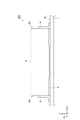
図1は、第1実施形態に係る電池パックの模式的な側面図である。図1に示されるように、第1実施形態に係る電池パック100は、筐体1と、電池モジュール2と、放熱シート(熱伝導部材)3と、固定部材4と、を備えている。電池モジュール2は、筐体1に収容されている。電池モジュール2は、筐体1の内面1sに固定されている。放熱シート3は、筐体1の内面1sと電池モジュール2との間に介在されている。固定部材4は、所定の方向(直交座標系Sのx軸方向)における電池モジュール2の一端2a及び他端2bにおいて、電池モジュール2を筐体1の内面1sに固定している。つまり、電池モジュール2は、所定の方向の一端2a及び他端2bにおいて内面1sに固定されている。
FIG. 1 is a schematic side view of the battery pack according to the first embodiment. As shown in FIG. 1, the
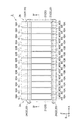
図2は、図1に示された電池モジュールの模式的な側面図である。図2に示されるように、電池モジュール2は、複数の電池ユニット(第1の電池ユニット)10A及び複数の電池ユニット(第2の電池ユニット)10Bと、拘束部材20と、を有する。電池ユニット10A,10Bは、所定の方向に沿って互いに積層されている。すなわち、ここでは、所定の方向は電池ユニット10A,10Bの積層方向である。
FIG. 2 is a schematic side view of the battery module shown in FIG. As shown in FIG. 2, the
電池ユニット10Aは、電池モジュール2の一端2a側及び他端2b側にそれぞれ配置されている。一端2a側の電池ユニット10Aの数、及び、他端2b側の電池ユニット10Aの数は、ここでは互いに同一であり、例えば4つである。電池ユニット10Bは、一端2a側の電池ユニット10Aと他端2b側の電池ユニット10Aのとの間に配置されている。ここでは、電池ユニット10Bは、所定の方向における電池モジュール2の中央部に配置されている。電池ユニット10Bの数は、例えば5つである。
The battery unit 10 </ b> A is disposed on one
拘束部材20は、所定の方向に沿って電池ユニット10A,10Bを互いに拘束する。拘束部材20は、一端2a及び他端2bのそれぞれに配置された一対のエンドプレート21と、エンドプレート21同士を互いに締結する複数の締結部材22と、を含む。締結部材22は、ボルト23とナット24とを含む。ボルト23は、一対のエンドプレート21に架け渡されるようにエンドプレート21及び電池ユニット10A,10Bに挿通される。ナット24は、そのボルト23に螺合されることにより、エンドプレート21同士を締結する。
The restraining
図3は、図2に示された電池ユニットの分解斜視図である。図3の(a)は電池ユニット10Aを示し、図3の(b)は電池ユニット10Bを示している。また、図4は、図2のIV−IV線に沿っての模式的な断面図である。図2〜4に示されるように、電池ユニット10Aは、電池セル11と、セルホルダ(第1のホルダ)30Aと、伝熱プレート(第1の伝熱プレート、第2の伝熱プレート)40と、を有する。
FIG. 3 is an exploded perspective view of the battery unit shown in FIG. 3A shows the
電池セル11は、電極組立体12と、電極組立体12を収容するケース13と、電極組立体12の電極(正極及び負極のそれぞれ)に電気的に接続された一対の端子14と、を有している。電極組立体12は、複数の正極(不図示)及び負極(不図示)と、正極と負極との間に配置されたセパレータ(不図示)と、を含む。正極及び負極は、所定の方向に沿って、セパレータを介して交互に積層されている。
The
ケース13は、直方体状を呈している。ケース13は、互いに対向する一対の側面(第2の面)13a,13bと、互いに対向する一対の側面(第1の面)13c,13dと、互いに対向する上面13e及び底面13fと、を含む。側面13a,13bは、所定の方向に沿った面である。側面13c,13dは、所定の方向に交差する面である。側面13a,13bは、側面13cと側面13dとを互いに接続する。端子14は、上面13eから突出している。
The
セルホルダ30Aは、電池セル11を保持する。より具体的には、セルホルダ30Aは、互いに対向する側壁部31A(第1の壁部)及び側壁部32と、背面部33及び底壁部34と、を含む。側壁部31A,32は、長方形板状を呈している。背面部33は、長方形板状を呈しており、側壁部31A,32の長手方向の一端部において側壁部31Aと側壁部32とを互いに接続している。底壁部34は、長方形板状を呈しており、側壁部31A,32の長手方向の他端部において側壁部31Aと側壁部32とを互いに接続している。
The
セルホルダ30Aにおいては、側壁部31A,32と背面部33及び底壁部34とによって、電池セル11が嵌め合される直方体状の空間部が画成されている。側壁部31A,32は、それぞれ、当該空間部に電池セル11が嵌め合されたときにケース13の側面13a,13b上に配置される。同様に、背面部33は、ケース13の上面13e近傍において、側面13d上に配置される。さらに、底壁部34は、ケース13の底面13f上に配置される。
In the
背面部33には、一対の突設部35が設けられている。突設部35は、直方体状を呈している。突設部35は、所定の方向に沿って延在している。突設部35は、上記空間部に電池セル11が嵌め合されたときに、ケース13の上面13e上であって、一対の端子14の間の位置に配置される。突設部35には、その延在方向に沿った挿通孔(第1の挿通孔)36が形成されている。この挿通孔36には、拘束部材20のボルト23が挿通される。
The
また、底壁部34における側壁部31A,32との接続部分には、一対の突設部37が設けられている。突設部37は、直方体状を呈している。突設部37は、所定の方向に沿って延在している。突設部37は、上記空間部に電池セル11が嵌め合されたときに、ケース13の底面13fにおける側面13a,13b側の端部に配置される。突設部37には、その延在方向に沿った挿通孔38が形成されている。この挿通孔38には、拘束部材20のボルト23が挿通される。
In addition, a pair of projecting
伝熱プレート40は、矩形板状の本体部(第1の本体部、第2の本体部)41と、矩形板状の延在部(第1の延在部、第2の延在部)42と、を含む。伝熱プレート40は、本体部41と延在部42とによってL字板状に形成されている。本体部41は、電池セル11(ケース13)の側面13d上に配置される。延在部42は、本体部41から所定の方向に沿って延び、電池セル11(ケース13)の側面13a上に配置される。特に、延在部42は、セルホルダ30Aの側壁部31Aを介して側面13a上に配置される。
The
伝熱プレート40は、本体部41において電池セル11に接触すると共に、延在部42における側壁部31Aと反対側の面において放熱シート3に接触する。つまり、伝熱プレート40は、電池セル11と筐体1とを熱的に接続する。特に、延在部42における側壁部31Aと反対側の面は、熱伝導部材を介して電池セル11と筐体1とを熱的に接続する伝熱面(第1の伝熱面、第2の伝熱面)40sである。
The
電池ユニット10Bは、電池セル11と、セルホルダ(第2のホルダ)30Bと、伝熱プレート40と、を含む。すなわち、電池ユニット10Bは、セルホルダ30Aに代えてセルホルダ30Bを有する点で電池ユニット10Aと相違しており、その他の点で電池ユニット10Aと同様である。セルホルダ30Bは、側壁部31Aに代えて側壁部(第2の壁部)31Bを含む点でセルホルダ30Aと相違しており、その他の点でセルホルダ30Aと同様である。
Battery unit 10 </ b> B includes a
セルホルダ30Bは、電池セル11を保持する。側壁部31Bは、長方形板状を呈している。セルホルダ30Bにおいては、側壁部31B,32と背面部33及び底壁部34とによって、電池セル11が嵌め合される直方体状の空間部が画成されている。側壁部31Bは、当該空間部に電池セル11が嵌め合されたときにケース13の側面13a上に配置される。伝熱プレート40の延在部42は、セルホルダ30Bの側壁部31Bを介して側面13a上に配置される。
The
ここでも、伝熱プレート40は、本体部41において電池セル11に接触すると共に、延在部42における側壁部31Bと反対側の面において放熱シート3に接触する。つまり、伝熱プレート40は、電池セル11と筐体1とを熱的に接続する。特に、延在部42における側壁部31Bと反対側の面は、熱伝導部材を介して電池セル11と筐体1とを熱的に接続する伝熱面40sである。
Also here, the
ここで、側壁部31Bの厚さTBは、側壁部31Aの厚さTAよりも大きい。したがって、電池ユニット10Bにおける伝熱プレート40の伝熱面40sは、電池ユニット10Aにおける伝熱プレート40の伝熱面40sよりも、筐体1の内面1s側に突出している。換言すれば、側壁部31Bは、電池ユニット10Bにおける伝熱プレート40の伝熱面40sが、電池ユニット10Aにおける伝熱プレート40の伝熱面40sよりも筐体1の内面1s側に突出するように、側壁部31Aよりも厚くされている、さらに換言すれば、電池ユニット10Bにおける伝熱プレート40の伝熱面40sは、電池ユニット10Aにおける伝熱プレート40の伝熱面40sにより規定される平面から電池モジュール2の外側に向けて突出している。
Here, the thickness TB of the
このため、図1に示されるように、電池モジュール2を筐体1に固定したときには、放熱シート3は、電池ユニット10Aが配置される電池モジュール2の一端2a側及び他端2b側において相対的に厚くなり、電池ユニット10Bが配置される電池モジュール2の中央部において相対的に薄くなる。
Therefore, as shown in FIG. 1, when the
以上説明したように、電池パック100においては、電池モジュール2は、放熱シート3を介在させた状態において、一端2a及び他端2bにおいて筐体1に固定される。また、電池パック100においては、電池モジュール2の一端2a側及び他端2b側に電池ユニット10Aが配置されており、それらの間に電池ユニット10Bが配置されている。つまり、電池ユニット10Aの電池セル11が、電池モジュール2の筐体1への固定部分に相対的に近く、電池ユニット10Bの電池セル11が、当該固定部分から相対的に遠い。
As described above, in the
これに対して、電池ユニット10Bの伝熱面40sは、電池ユニット10Aの伝熱面40sによりも筐体1の内面1s側に突出している。つまり、この電池パック100においては、電池モジュール2を筐体1に固定したときに、その固定部分から相対的に遠い電池セル11の伝熱面40sが、より筐体1の内面1sに近接する。このため、電池モジュール2の筐体1への固定部分から相対的に遠い電池セル11の伝熱面40sが筐体1及び放熱シート3から離間することが抑制される。よって、電池セル11間の温度差を小さくすることができる。
On the other hand, the
また、電池パック100においては、電池ユニット10Bにおけるセルホルダ30Bの側壁部31Bの厚さTBを、電池ユニット10Aにおけるセルホルダ30Aの側壁部31Aよりも厚くしている。これにより、簡単な構成で確実に電池ユニット10Bにおける伝熱プレート40の伝熱面40sを電池ユニット10Aにおける伝熱プレート40の伝熱面40sよりも筐体1の内面1s側に突出させることができる。
In the
なお、図5の(a)に示されるように、電池ユニット10Bにおける伝熱プレート40の伝熱面40sを、電池ユニット10Aにおける伝熱プレート40の伝熱面40sよりも筐体1の内面1s側に突出させるに際して、側壁部31Bと延在部42との間に板状のスペーサ39を介在させ、側壁部31B及びスペーサ39の合計の厚さTBを側壁部31Aの厚さTAよりも厚くしてもよい。
As shown in FIG. 5 (a), the
また、図5の(b)に示されるように、電池ユニット10Bにおける伝熱プレート40の伝熱面40sを、電池ユニット10Aにおける伝熱プレート40の伝熱面40sよりも筐体1側に突出させるに際して、電池ユニット10Bにおける伝熱プレート40の延在部42の厚さTDを、電池ユニット10Aにおける伝熱プレート40の延在部42の厚さTCよりも厚くしてもよい。この場合、電池ユニット10Bの伝熱プレート40の全体を厚くしてもよい。
[第2実施形態]
Further, as shown in FIG. 5B, the
[Second Embodiment]
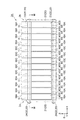
図6は、第2実施形態に係る電池パックの模式的な側面図である。図6に示されるように、第2実施形態に係る電池パック100Aは、電池モジュール2に代えて電池モジュール2Aを備える点で電池パック100と相違しており、その他の点で電池パック100と同様である。図7は、図6に示された電池モジュールの模式的な側面図である。図7に示されるように、電池モジュール2Aは、電池ユニット10Bに代えて電池ユニット(第2の電池ユニット)10Cを有する点で電池モジュール2と相違しており、その他の点で電池モジュール2と同様である。
FIG. 6 is a schematic side view of the battery pack according to the second embodiment. As shown in FIG. 6, the
電池ユニット10Cは、電池ユニット10Aと共に所定の方向に沿って積層されており、拘束部材20により拘束されている。電池ユニット10Cは、所定の方向における電池モジュール2Aの一端2a側の電池ユニット10Aと、他端2b側の電池ユニット10Aとの間に配置されている。ここでは、電池ユニット10Cの数は、例えば5つである。電池ユニット10Cは、セルホルダ30Aに代えてセルホルダ(第2のホルダ)30Cを有する点で電池ユニット10Aと相違しており、その他の点で電池ユニット10Aと同様である。
The battery unit 10 </ b> C is stacked along the battery unit 10 </ b> A along a predetermined direction and is restrained by the restraining
図8は、図7のVIII−VIII線に沿っての模式的な断面図である。図8に示されるように、セルホルダ30Cは、まず、突設部35に代えて突設部35Cを含む点でセルホルダ30Aと相違している。突設部35Cには、挿通孔(第2の挿通孔)36Cが設けられている。ここでは、突設部35C及び挿通孔36Cの形状は、突設部35及び挿通孔36と同様である。これに対して、セルホルダ30Cにおける突設部35C及び挿通孔36Cの設けられた位置は、セルホルダ30Aにおける突設部35及び挿通孔36が設けられた位置と相違している。
FIG. 8 is a schematic cross-sectional view taken along line VIII-VIII in FIG. As shown in FIG. 8, the
より具体的には、突設部35C及び挿通孔36Cは、電池ユニット10Cにおける伝熱面40sと挿通孔36Cとの間の距離DCが、電池ユニット10Aにおける伝熱面40sと挿通孔36との間の距離DAよりも大きくなるように設けられている。したがって、挿通孔36と共に挿通孔36Cにボルト23を挿通したときには、電池ユニット10Cにおける伝熱面40sが、電池ユニット10Aにおける伝熱面40sよりも筐体1の内面1s側に突出する。
More specifically, the protruding
なお、挿通孔36と伝熱面40sとの距離DAは、例えば、挿通孔36の中心線Cと伝熱面40sとの間の距離である。また、挿通孔36Cと伝熱面40sとの距離DCは、例えば、挿通孔36Cの中心線Cと伝熱面40sとの距離である。また、ここでは図示を省略するが、底壁部34側の突設部37及び挿通孔38についても、同様に構成される。
The distance DA between the
したがって、電池ユニット10A,10Cを拘束部材20により一括して拘束すると、伝熱面40sごと電池ユニット10Cが筐体1の内面1s側にシフトする。これにより、図6に示されるように、電池モジュール2Aの全体としては、一端2a側及び他端2b側に比べて中央側において筐体1の内面1s側に突出するように湾曲した形状となる。また、電池モジュール2Aを筐体1に固定したときには、放熱シート3は、電池ユニット10Aが配置される電池モジュール2の一端2a側及び他端2b側において相対的に厚くなり、電池ユニット10Cが配置される電池モジュール2の中央部において相対的に薄くなる。
Therefore, when the
以上説明したように、電池パック100Aにおいても、電池パック100と同様の理由から、電池セル11間の温度差を小さくすることができる。特に、電池パック100Aにおいては、電池ユニット10Cにおける伝熱面40sと挿通孔36Cとの間の距離DCは、電池ユニット10Aにおける伝熱面40sと挿通孔36との間の距離DAよりも大きくされている。このため、挿通孔36と共に挿通孔36Cにボルト23を挿通したときに、電池ユニット10Cにおける伝熱面40sが電池ユニット10Aにおける伝熱面40sよりも筐体1の内面1s側に突出する。このようにすることにより、簡単な構成で確実に電池ユニット10Cの伝熱面40sを電池ユニット10Aの伝熱面40sよりも突出させることができる。
As described above, also in the
以上の実施形態は、本発明に係る電池パックの一実施形態について説明したものである。したがって、本発明に係る電池パックは、上述した電池パック100,100Aに限定されない。本発明に係る電池パックは、各請求項の要旨を変更しない範囲において、上述した電池パック100,100Aを任意に変更したものとすることができる。 The above embodiment describes one embodiment of the battery pack according to the present invention. Therefore, the battery pack according to the present invention is not limited to the above-described battery packs 100 and 100A. In the battery pack according to the present invention, the above-described battery packs 100 and 100A can be arbitrarily changed without changing the gist of each claim.
例えば、電池セル11の膨張を吸収するため、電池モジュール2,2Aに弾性部材を設ける場合がある。その場合、例えば、電池モジュール2,2Aの一端2a側において、エンドプレート21と電池ユニット10A(電池セル11)との間にゴムやスポンジ等の弾性部材を介在させることができる。このように、電池モジュール2,2Aの一端2a側に弾性部材を介在させると、放熱シート3から離間しやすい電池セル11が一端2a側(すなわち、弾性部材が配置された側)にシフトする。
For example, in order to absorb expansion of the
したがって、この場合には、一端2a側の電池ユニット10Aを他端2b側の電池ユニット10Aに比べて少なくし、電池ユニット10B,10Cをより一端2a側まで配置すれば、より一端2a側においても電池セル11が放熱シート3から離間することが抑制される。よって、一端2a側に弾性部材を設けた場合でも、確実に電池セル11間の温度差を小さくすることができる。
Therefore, in this case, if the
なお、この場合、一例として、一端2a側の電池ユニット10Aの数を2つとし、他端2b側の電池ユニット10Aを6つとすれば、電池ユニット10B,10Cの数を変更することなく、一端2a側に偏るように電池ユニット10B,10Cを配置させることができる。上述した電池ユニット10Aの数は、あくまで一例であり、電池ユニット10Aの数は、放熱シート3からの反力の分布や、電池モジュール2,2Aの各部の固定強度の分布等の兼ね合いから、適宜設定することができる。
In this case, as an example, if the number of the
さらに、電池パック100Aにおいては、伝熱プレート40を用いずに、電池ユニット10A,10Cの各電池セル11を直接放熱シート3に接触させる構成としてもよい。この場合、放熱シート3を介して電池セル11と筐体1とを熱的に接続する伝熱面は、例えば、各電池セル11の側面13aとすることができる。
Further, in the
ここで、上記実施形態においては、第1実施形態でセルホルダの壁部の厚さを変更して一部の伝熱面を突出させる態様について説明し、第2実施形態でセルホルダのボルトの挿通孔の位置をシフトさせて一部の伝熱面を突出させる態様について説明した。しかしながら、これらの態様は互いに同時に採用することができる。また、上記実施形態においては、電池ユニット10Aと電池ユニット10B、又は、電池ユニット10Aと電池ユニット10Cのように、伝熱面40sの内面1sへの突出量(内面1sに対する伝熱面40sの位置)が互いに異なる2種類の電池ユニットを用いる場合について説明した。しかしながら、伝熱面40sの突出量が互いに異なる3種類以上の電池ユニットを用いてもよい。
Here, in the said embodiment, the aspect which changes the thickness of the wall part of a cell holder in 1st Embodiment, and protrudes one part heat-transfer surface is demonstrated, The insertion hole of the bolt of a cell holder in 2nd Embodiment The mode of shifting the position of and projecting some heat transfer surfaces has been described. However, these aspects can be employed simultaneously. Moreover, in the said embodiment, like the
以上の実施形態について、以下に付記する。 About the above embodiment, it adds to the following.
(付記1)
所定の方向における一端及び他端において外部部品(例えば電池パックの筐体)に固定される電池モジュールであって、
前記所定の方向に沿って積層された複数の第1の電池ユニット及び複数の第2の電池ユニットと、
前記所定の方向に沿って前記第1の電池ユニット及び前記第2の電池ユニットを拘束する拘束部材と、を備え、
前記第1の電池ユニットは、電池セルと、前記電池セルを保持する第1のホルダと、前記電池セルと前記外部部品とを熱的に接続するための第1の伝熱面と、を有し、前記一端側及び前記他端側に配置され、
前記第2の電池ユニットは、前記電池セルと、前記電池セルを保持する第2のホルダと、前記電池セルと前記筐体とを熱的に接続するための第2の伝熱面と、を有し、前記一端側の前記第1の電池ユニットと前記他端側の前記第1の電池ユニットとの間に配置され、
前記第2の伝熱面は、前記第1の伝熱面よりも前記外部部品側に突出している、
電池モジュール。
(Appendix 1)
A battery module fixed to an external component (for example, a battery pack housing) at one end and the other end in a predetermined direction,
A plurality of first battery units and a plurality of second battery units stacked along the predetermined direction;
A restraining member that restrains the first battery unit and the second battery unit along the predetermined direction,
The first battery unit includes a battery cell, a first holder for holding the battery cell, and a first heat transfer surface for thermally connecting the battery cell and the external component. And disposed on the one end side and the other end side,
The second battery unit includes the battery cell, a second holder for holding the battery cell, and a second heat transfer surface for thermally connecting the battery cell and the housing. And is disposed between the first battery unit on the one end side and the first battery unit on the other end side,
The second heat transfer surface protrudes to the external component side than the first heat transfer surface,
Battery module.
1…筐体、1s…内面、2,2A…電池モジュール、2a…一端、2b…他端、3…放熱シート(熱伝導部材)、10A…電池ユニット(第1の電池ユニット)、10B,10C…電池ユニット(第2の電池ユニット)、11…電池セル、13d…側面(第1の面)、13a…側面(第2の面)、20…拘束部材、21…エンドプレート、23…ボルト、30A…セルホルダ(第1のホルダ)、30B,30C…セルホルダ(第2のホルダ)、31A…側壁部(第1の壁部)、31B…側壁部(第2の壁部)、36…挿通孔(第1の挿通孔)、36C…挿通孔(第2の挿通孔)、40…伝熱プレート(第1の伝熱プレート、第2の伝熱プレート)、40s…伝熱面(第1の伝熱面、第2の伝熱面)、41…本体部(第1の本体部、第2の本体部)、42…延在部(第1の延在部、第2の延在部)、100,100A…電池パック。 DESCRIPTION OF SYMBOLS 1 ... Housing | casing, 1s ... Inner surface, 2, 2A ... Battery module, 2a ... One end, 2b ... Other end, 3 ... Radiation sheet (heat conduction member), 10A ... Battery unit (1st battery unit), 10B, 10C ... battery unit (second battery unit), 11 ... battery cell, 13d ... side surface (first surface), 13a ... side surface (second surface), 20 ... restraining member, 21 ... end plate, 23 ... bolt, 30A ... Cell holder (first holder), 30B, 30C ... Cell holder (second holder), 31A ... Side wall (first wall), 31B ... Side wall (second wall), 36 ... Insertion hole (First insertion hole), 36C ... insertion hole (second insertion hole), 40 ... heat transfer plate (first heat transfer plate, second heat transfer plate), 40s ... heat transfer surface (first Heat transfer surface, second heat transfer surface), 41 ... main body (first main body, second main body) ), 42 ... extending portion (first extending portion, a second extending portion), 100, 100A ... battery pack.
Claims (4)
前記筐体に収容され前記筐体の内面に固定される電池モジュールと、
前記電池モジュールと前記内面との間に介在された熱伝導部材と、
を備える電池パックであって、
前記電池モジュールは、所定の方向に沿って積層された複数の第1の電池ユニット及び複数の第2の電池ユニットと、前記所定の方向に沿って前記第1の電池ユニット及び前記第2の電池ユニットを拘束する拘束部材と、を有し、前記所定の方向の一端及び他端において前記内面に固定され、
前記第1の電池ユニットは、電池セルと、前記電池セルを保持する第1のホルダと、前記熱伝導部材を介して前記電池セルと前記筐体とを熱的に接続するための第1の伝熱面と、を有し、前記一端側及び前記他端側に配置され、
前記第2の電池ユニットは、前記電池セルと、前記電池セルを保持する第2のホルダと、前記熱伝導部材を介して前記電池セルと前記筐体とを熱的に接続するための第2の伝熱面と、を有し、前記一端側の前記第1の電池ユニットと前記他端側の前記第1の電池ユニットとの間に配置され、
前記第2の伝熱面は、前記第1の伝熱面よりも前記内面側に突出している、
電池パック。 A housing,
A battery module housed in the housing and fixed to the inner surface of the housing;
A heat conducting member interposed between the battery module and the inner surface;
A battery pack comprising:
The battery module includes a plurality of first battery units and a plurality of second battery units stacked along a predetermined direction, and the first battery unit and the second battery along the predetermined direction. A restraining member that restrains the unit, and is fixed to the inner surface at one end and the other end in the predetermined direction,
The first battery unit includes a battery cell, a first holder for holding the battery cell, and a first for thermally connecting the battery cell and the housing via the heat conducting member. A heat transfer surface, disposed on the one end side and the other end side,
The second battery unit includes a second battery for thermally connecting the battery cell, the second holder for holding the battery cell, and the battery cell and the housing via the heat conducting member. A heat transfer surface, and is disposed between the first battery unit on the one end side and the first battery unit on the other end side,
The second heat transfer surface protrudes closer to the inner surface than the first heat transfer surface.
Battery pack.
前記第1のホルダは、前記第2の面上に配置される第1の壁部を含み、
前記第2のホルダは、前記第2の面上に配置される第2の壁部を含み、
前記第1の電池ユニットは、前記第1の面上に配置される第1の本体部と、前記第1の本体部から前記所定の方向に延在して前記第2の面上に配置される第1の延在部と、を含む第1の伝熱プレートを有し、
前記第2の電池ユニットは、前記第1の面上に配置される第2の本体部と、前記第2の本体部から前記所定の方向に延在して前記第2の面上に配置される第2の延在部と、を含む第2の伝熱プレートを有し、
前記第1の延在部は、前記第1の壁部を介して前記第2の面上に配置され、
前記第2の延在部は、前記第2の壁部を介して前記第2の面上に配置され、
前記第1の伝熱面は、前記第1の延在部における前記第1の壁部と反対側の面であり、
前記第2の伝熱面は、前記第2の延在部における前記第2の壁部と反対側の面であり、
前記第2の壁部は、前記第1の壁部よりも厚くされている、
請求項1に記載の電池パック。 The battery cell includes a first surface that intersects the predetermined direction, and a second surface along the predetermined direction,
The first holder includes a first wall portion disposed on the second surface,
The second holder includes a second wall portion disposed on the second surface,
The first battery unit is disposed on the second surface extending in the predetermined direction from the first main body portion disposed on the first surface, and the first body portion. A first heat transfer plate including a first extension part,
The second battery unit is disposed on the second surface extending from the second main body portion in the predetermined direction from the second main body portion disposed on the first surface. A second heat transfer plate including a second extension part,
The first extending portion is disposed on the second surface via the first wall portion,
The second extension portion is disposed on the second surface via the second wall portion,
The first heat transfer surface is a surface opposite to the first wall portion in the first extension portion,
The second heat transfer surface is a surface of the second extension portion opposite to the second wall portion,
The second wall is thicker than the first wall,
The battery pack according to claim 1.
前記第2のホルダには、前記ボルトが挿通される第2の挿通孔が設けられており、
前記第2の挿通孔と前記第2の伝熱面との間の距離は、前記第1の伝熱面と前記第1の挿通孔との間の距離よりも大きい、
請求項1又は2に記載の電池パック。 The first holder is provided with a first insertion hole through which a bolt is inserted,
The second holder is provided with a second insertion hole through which the bolt is inserted,
The distance between the second insertion hole and the second heat transfer surface is greater than the distance between the first heat transfer surface and the first insertion hole.
The battery pack according to claim 1 or 2.
前記一端側の前記第1の電池ユニットの数は、前記他端側の前記第1の電池ユニットの数よりも少ない、
請求項1〜3のいずれか一項に記載の電池パック。 The restraining member includes a pair of end plates disposed at the one end and the other end, and an elastic member interposed between the end plate and the first battery unit on the one end side,
The number of the first battery units on the one end side is less than the number of the first battery units on the other end side,
The battery pack according to any one of claims 1 to 3.
Priority Applications (1)
| Application Number | Priority Date | Filing Date | Title |
|---|---|---|---|
| JP2015127726A JP2017010879A (en) | 2015-06-25 | 2015-06-25 | Battery pack |
Applications Claiming Priority (1)
| Application Number | Priority Date | Filing Date | Title |
|---|---|---|---|
| JP2015127726A JP2017010879A (en) | 2015-06-25 | 2015-06-25 | Battery pack |
Publications (1)
| Publication Number | Publication Date |
|---|---|
| JP2017010879A true JP2017010879A (en) | 2017-01-12 |
Family
ID=57761774
Family Applications (1)
| Application Number | Title | Priority Date | Filing Date |
|---|---|---|---|
| JP2015127726A Pending JP2017010879A (en) | 2015-06-25 | 2015-06-25 | Battery pack |
Country Status (1)
| Country | Link |
|---|---|
| JP (1) | JP2017010879A (en) |
Cited By (3)
| Publication number | Priority date | Publication date | Assignee | Title |
|---|---|---|---|---|
| JP2018129240A (en) * | 2017-02-09 | 2018-08-16 | 日産自動車株式会社 | Assembled battery, battery pack, manufacturing method of assembled battery, and manufacturing method of battery pack |
| JP2020080218A (en) * | 2018-11-12 | 2020-05-28 | トヨタ自動車株式会社 | Battery pack |
| CN111712940A (en) * | 2017-12-18 | 2020-09-25 | 日本汽车能源株式会社 | Battery module |
Citations (2)
| Publication number | Priority date | Publication date | Assignee | Title |
|---|---|---|---|---|
| JP2013084444A (en) * | 2011-10-08 | 2013-05-09 | Sanyo Electric Co Ltd | Electric power supply apparatus and vehicle including the same |
| JP2014116193A (en) * | 2012-12-10 | 2014-06-26 | Toyota Industries Corp | Battery module and manufacturing method for the same |
-
2015
- 2015-06-25 JP JP2015127726A patent/JP2017010879A/en active Pending
Patent Citations (2)
| Publication number | Priority date | Publication date | Assignee | Title |
|---|---|---|---|---|
| JP2013084444A (en) * | 2011-10-08 | 2013-05-09 | Sanyo Electric Co Ltd | Electric power supply apparatus and vehicle including the same |
| JP2014116193A (en) * | 2012-12-10 | 2014-06-26 | Toyota Industries Corp | Battery module and manufacturing method for the same |
Cited By (6)
| Publication number | Priority date | Publication date | Assignee | Title |
|---|---|---|---|---|
| JP2018129240A (en) * | 2017-02-09 | 2018-08-16 | 日産自動車株式会社 | Assembled battery, battery pack, manufacturing method of assembled battery, and manufacturing method of battery pack |
| CN111712940A (en) * | 2017-12-18 | 2020-09-25 | 日本汽车能源株式会社 | Battery module |
| US11563251B2 (en) | 2017-12-18 | 2023-01-24 | Vehicle Energy Japan Inc. | Battery module |
| CN111712940B (en) * | 2017-12-18 | 2023-07-18 | 日本汽车能源株式会社 | Battery module |
| JP2020080218A (en) * | 2018-11-12 | 2020-05-28 | トヨタ自動車株式会社 | Battery pack |
| JP7161672B2 (en) | 2018-11-12 | 2022-10-27 | トヨタ自動車株式会社 | assembled battery |
Similar Documents
| Publication | Publication Date | Title |
|---|---|---|
| WO2019151037A1 (en) | Battery module and battery pack | |
| EP2562842B1 (en) | Battery module | |
| US20150064543A1 (en) | Battery module | |
| JP6926630B2 (en) | Battery module | |
| US10333186B2 (en) | Electricity storage pack | |
| JP6627265B2 (en) | Battery pack | |
| CN112952249B (en) | Battery pack | |
| JP2017228364A (en) | Battery pack | |
| WO2019049760A1 (en) | Battery module | |
| JP6380704B2 (en) | Power storage device pack | |
| JP6609989B2 (en) | Battery module | |
| JP2017010879A (en) | Battery pack | |
| CN111712940B (en) | Battery module | |
| JP6819159B2 (en) | Battery module | |
| JP6690452B2 (en) | Battery module | |
| JP7134626B2 (en) | power storage device | |
| JP2015133289A (en) | Battery module and holder for battery module | |
| JP6631869B2 (en) | Power storage device | |
| JP7108909B2 (en) | Restraining member and battery module | |
| JP2018063914A5 (en) | ||
| JP2014022239A (en) | Battery pack | |
| US10069178B2 (en) | Battery cell having connecting protrusion for voltage sensing and battery module comprising the same | |
| JP2014022238A (en) | Battery pack | |
| JP2014086281A (en) | Power storage module | |
| JP2014022237A (en) | Battery pack |
Legal Events
| Date | Code | Title | Description |
|---|---|---|---|
| A621 | Written request for application examination |
Free format text: JAPANESE INTERMEDIATE CODE: A621 Effective date: 20180301 |
|
| A977 | Report on retrieval |
Free format text: JAPANESE INTERMEDIATE CODE: A971007 Effective date: 20181107 |
|
| A131 | Notification of reasons for refusal |
Free format text: JAPANESE INTERMEDIATE CODE: A131 Effective date: 20181113 |
|
| A521 | Request for written amendment filed |
Free format text: JAPANESE INTERMEDIATE CODE: A523 Effective date: 20181221 |
|
| A02 | Decision of refusal |
Free format text: JAPANESE INTERMEDIATE CODE: A02 Effective date: 20190319 |