KR20120037726A - Apparatus for shifting phasor by-directionally and distributedly - Google Patents
Apparatus for shifting phasor by-directionally and distributedly Download PDFInfo
- Publication number
- KR20120037726A KR20120037726A KR1020100099357A KR20100099357A KR20120037726A KR 20120037726 A KR20120037726 A KR 20120037726A KR 1020100099357 A KR1020100099357 A KR 1020100099357A KR 20100099357 A KR20100099357 A KR 20100099357A KR 20120037726 A KR20120037726 A KR 20120037726A
- Authority
- KR
- South Korea
- Prior art keywords
- port
- unit
- twenty
- mos transistor
- electrical signal
- Prior art date
- Legal status (The legal status is an assumption and is not a legal conclusion. Google has not performed a legal analysis and makes no representation as to the accuracy of the status listed.)
- Granted
Links
Images
Classifications
-
- H—ELECTRICITY
- H03—ELECTRONIC CIRCUITRY
- H03H—IMPEDANCE NETWORKS, e.g. RESONANT CIRCUITS; RESONATORS
- H03H11/00—Networks using active elements
- H03H11/02—Multiple-port networks
- H03H11/16—Networks for phase shifting
- H03H11/20—Two-port phase shifters providing an adjustable phase shift
-
- H—ELECTRICITY
- H03—ELECTRONIC CIRCUITRY
- H03H—IMPEDANCE NETWORKS, e.g. RESONANT CIRCUITS; RESONATORS
- H03H11/00—Networks using active elements
- H03H11/02—Multiple-port networks
- H03H11/16—Networks for phase shifting
- H03H11/22—Networks for phase shifting providing two or more phase shifted output signals, e.g. n-phase output
-
- H—ELECTRICITY
- H03—ELECTRONIC CIRCUITRY
- H03H—IMPEDANCE NETWORKS, e.g. RESONANT CIRCUITS; RESONATORS
- H03H7/00—Multiple-port networks comprising only passive electrical elements as network components
- H03H7/01—Frequency selective two-port networks
- H03H7/0115—Frequency selective two-port networks comprising only inductors and capacitors
-
- H—ELECTRICITY
- H03—ELECTRONIC CIRCUITRY
- H03H—IMPEDANCE NETWORKS, e.g. RESONANT CIRCUITS; RESONATORS
- H03H9/00—Networks comprising electromechanical or electro-acoustic elements; Electromechanical resonators
- H03H9/66—Phase shifters
Landscapes
- Cable Transmission Systems, Equalization Of Radio And Reduction Of Echo (AREA)
Abstract
본 발명은 인가되는 전기 신호를 전달하는 제1기준부, 인가되는 전기 신호를, 제1기준부에의해서 전달되는 전기 신호의 위상보다 소정의 각도만큼 천이하여 전달하는 제1천이부, 입력되는 전기 신호를 제1기준부나 제1천이부로 전달하는 제1입출력부, 제1기준부나 제1천이부로부터 인가되는 전기 신호를 전달하는 제2기준부, 제1기준부나 제1천이부로부터 인가되는 전기 신호를, 제2기준부에의해서 전달되는 전기 신호의 위상보다 소정의 각도만큼 천이하여 전달하는 제2천이부, 제1기준부나 제1천이부로부터 인가되는 전기 신호를 제2기준부나 제2천이부로 전달하는 제1포웨이 스위칭부 및 제2기준부나 제2천이부로부터 인가되는 전기 신호를 출력하는 제2입출력부를 포함하는 양방향 분산 위상 천이 장치를 제공한다.The present invention provides a first reference unit for transmitting an applied electric signal, a first transition unit for transferring an applied electric signal by a predetermined angle from a phase of an electric signal transmitted by the first reference unit, and transferring the input electric signal. A first input-output unit that transmits a signal to the first reference unit or the first transition unit, a second reference unit that transmits an electric signal applied from the first reference unit or the first transition unit, and an electricity applied from the first reference unit or the first transition unit The second reference unit or the second transition unit transmits an electrical signal applied from the second transition unit, the first reference unit, or the first transition unit to shift the signal by a predetermined angle from the phase of the electrical signal transmitted by the second reference unit. The present invention provides a bidirectional distributed phase shifting device including a first four-way switching unit for transmitting a second input and output unit for outputting an electrical signal applied from a second reference unit or a second transition unit.
Description
본 발명은 양방향 분산 위상 천이 장치에 관한 것으로서, 보다 상세하게는 인가되는 전기 신호의 위상을 소정의 각도만큼 천이시키기 위해서 다단계로 천이 회로를 구성하는 경우에 포웨이(four-way) 스위칭 소자를 채용한 양방향 분산 위상 천이 장치에 관한 것이다.
BACKGROUND OF THE INVENTION 1. Field of the Invention The present invention relates to a bidirectional distributed phase shifting device, and more particularly, employs a four-way switching element when a transition circuit is configured in multiple stages to shift a phase of an applied electric signal by a predetermined angle. One bidirectional distributed phase shifting device is disclosed.
인가되는 전기 신호의 위상을 소정의 각도만큼 천이시키기 위해서는 일반적으로, 다단계로 천이 회로가 구성된다.In order to shift the phase of an applied electric signal by a predetermined angle, a transition circuit is generally configured in multiple stages.
이러한 다단계의 천이 회로는 종래에는 각각의 천이 회로마다 2 개의 SPDT(Single Pole Double Throw) 스위칭 소자를 채용하고 있었다.Such a multi-stage transition circuit has conventionally employed two single pole double throw (SPDT) switching elements for each transition circuit.
그런데, 각각의 천이 회로마다 2 개의 SPDT 스위칭 장치를 이용하여 연결하는 경우에는 SPDT 각각에서 스위칭 손실이 발생하여 여러 단계의 천이 회로를 연결시키는 것이 어려웠다.
However, when two SPDT switching devices are connected to each transition circuit, switching losses occur in each of the SPDTs, making it difficult to connect the transition circuits of various stages.
따라서 본 발명은 종래 기술의 문제점을 해결하기 위하여 안출된 것으로, 본 발명이 이루고자 하는 기술적 과제는, 인가되는 전기 신호의 위상을 소정의 각도만큼 천이시키기 위해서 다단계로 천이 회로를 구성하는 경우에 포웨이(four-way) 스위칭 소자를 채용한 양방향 분산 위상 천이 장치를 제공하는 것이다.Therefore, the present invention has been made to solve the problems of the prior art, and the technical problem to be achieved by the present invention is to configure the transition circuit in a multi-step in order to shift the phase of the applied electrical signal by a predetermined angle A bidirectional distributed phase shifting device employing a four-way switching element is provided.
본 발명이 이루고자 하는 기술적 과제들은 이상에서 언급한 기술적 과제들로 제한되지 않으며, 언급되지 않은 또 다른 기술적 과제들은 아래의 기재로부터 본 발명이 속하는 기술분야에서 통상의 지식을 가진 자에게 명확하게 이해될 수 있을 것이다.
It is to be understood that both the foregoing general description and the following detailed description are exemplary and explanatory and are not intended to limit the invention to the precise forms disclosed. Other objects, which will be apparent to those skilled in the art, It will be possible.
상기와 같은 목적을 달성하기 위하여 본 발명의 일 실시예에 따른 양방향 분산 위상 천이 장치는 인가되는 전기 신호를 전달하는 제1기준부, 인가되는 전기 신호를, 상기 제1기준부에의해서 전달되는 전기 신호의 위상보다 소정의 각도만큼 천이하여 전달하는 제1천이부, 입력되는 전기 신호를 상기 제1기준부나 상기 제1천이부로 전달하는 제1입출력부, 상기 제1기준부나 상기 제1천이부로부터 인가되는 전기 신호를 전달하는 제2기준부, 상기 제1기준부나 상기 제1천이부로부터 인가되는 전기 신호를, 상기 제2기준부에의해서 전달되는 전기 신호의 위상보다 소정의 각도만큼 천이하여 전달하는 제2천이부, 상기 제1기준부나 상기 제1천이부로부터 인가되는 전기 신호를 상기 제2기준부나 상기 제2천이부로 전달하는 제1포웨이 스위칭부 및 상기 제2기준부나 상기 제2천이부로부터 인가되는 전기 신호를 출력하는 제2입출력부를 포함한다.In order to achieve the above object, a bidirectional distributed phase shifting apparatus according to an embodiment of the present invention includes a first reference unit for transmitting an applied electric signal and an electric signal applied by the first reference unit. A first transition unit for shifting and transmitting a phase by a predetermined angle from the phase of the signal, a first input / output unit for transmitting an input electrical signal to the first reference unit or the first transition unit, from the first reference unit or the first transition unit The second reference unit for transmitting the applied electrical signal, the electrical signal applied from the first reference unit or the first transition unit is transferred by transitioning by a predetermined angle than the phase of the electrical signal transmitted by the second reference unit The second transition unit, the first four-way switching unit and the second reference unit for transmitting an electrical signal applied from the first reference unit or the first transition unit to the second reference unit or the second transition unit. Or a second input / output unit for outputting an electrical signal applied from the second transition unit.
본 발명의 일 실시예에 따른 양방향 분산 위상 천이 장치는 상기 제1기준부 또는 상기 제2기준부 중 어느 하나가 제11커패시터, 상기 제11커패시터에 연결되는 제12커패시터 및 상기 제11커패시터와 상기 제12커패시터의 접점과 접지 사이에 연결되는 제11인덕터를 포함하는 것이 바람직하다.In the bidirectional distributed phase shifting device according to an embodiment of the present invention, either the first reference unit or the second reference unit is an eleventh capacitor, a twelfth capacitor connected to the eleventh capacitor, and the eleventh capacitor and the It is preferable to include an eleventh inductor connected between the contact of the twelfth capacitor and the ground.
본 발명의 일 실시예에 따른 양방향 분산 위상 천이 장치는 상기 제1천이부 또는 상기 제2천이부 중 어느 하나가 제21인덕터, 상기 제21인덕터에 연결되는 제22인덕터 및 상기 제21인덕터와 상기 제22인덕터의 접점과 접지 사이에 연결되는 제21커패시터를 포함하는 것이 바람직하다.In the bidirectional distributed phase shifting device according to an embodiment of the present invention, any one of the first transition unit and the second transition unit may include a twenty-first inductor, a twenty-second inductor connected to the twenty-first inductor, and the twenty-first inductor. It is preferable to include a twenty-first capacitor connected between the contact point of the twenty-second inductor and the ground.
본 발명의 일 실시예에 따른 양방향 분산 위상 천이 장치는 상기 제1기준부 또는 상기 제2기준부 중 어느 하나가 제31인덕터, 상기 제31인덕터에 연결되는 제32인덕터 및 상기 제31인덕터와 상기 제32인덕터의 접점과 접지 사이에 연결되는 제31커패시터를 포함하는 것이 바람직하다.In the bidirectional distributed phase shifting apparatus according to an embodiment of the present invention, one of the first reference unit or the second reference unit may include a thirty-first inductor connected to the thirty-first inductor and the thirty-first inductor. It is preferable to include a thirty-one capacitor connected between the contact point of the thirty-second inductor and the ground.
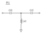
본 발명의 일 실시예에 따른 양방향 분산 위상 천이 장치는 상기 제1천이부 또는 상기 제2천이부 중 어느 하나가 제41커패시터, 상기 제41커패시터에 연결되는 제42커패시터 및 상기 제41커패시터와 상기 제42커패시터의 접점과 접지 사이에 연결되는 제41인덕터를 포함하는 것이 바람직하다.In the bidirectional distributed phase shifting device according to an embodiment of the present invention, any one of the first transition unit and the second transition unit may include a 41 th capacitor, a 42 th capacitor, and the 41 th capacitor and the 41 th capacitor. It is preferable to include a forty-one inductor connected between the contact of the 42nd capacitor and the ground.
본 발명의 일 실시예에 따른 양방향 분산 위상 천이 장치는 상기 제1포웨이 스위칭부가 제11포트와 제21포트사이에 연결되는 제1모스트랜지스터를 포함하며, 상기 제1모스트랜지스터가 턴온되는 경우에 상기 제11포트와 상기 제21포트사이에 전기 신호를 전달하는 제11스위칭부, 상기 제11포트와 제22포트사이에 연결되는 제2모스트랜지스터를 포함하며, 상기 제2모스트랜지스터가 턴온되는 경우에 상기 제11포트와 상기 제22포트사이에 전기 신호를 전달하는 제12스위칭부, 제12포트와 상기 제21포트사이에 연결되는 제3모스트랜지스터를 포함하며, 상기 제3모스트랜지스터가 턴온되는 경우에 상기 제12포트와 상기 제21포트사이에 전기 신호를 전달하는 제21스위칭부 및 상기 제12포트와 상기 제22포트사이에 연결되는 제4모스트랜지스터를 포함하며, 상기 제4모스트랜지스터가 턴온되는 경우에 상기 제12포트와 상기 제22포트사이에 전기 신호를 전달하는 제22스위칭부를 포함하는 것이 바람직하다.The bidirectional distributed phase shifting device according to an embodiment of the present invention includes a first MOS transistor connected between the eleventh port and the twenty-first port, and wherein the first four-way switching unit is turned on when the first MOS transistor is turned on. An eleventh switching unit configured to transfer an electrical signal between the eleventh port and the twenty-first port, and a second MOS transistor connected between the eleventh port and the twenty-second port, and wherein the second MOS transistor is turned on. A twelfth switching unit configured to transfer an electrical signal between the eleventh port and the twenty-second port, and a third MOS transistor connected between the twelfth port and the twenty-first port, wherein the third MOS transistor is turned on. And a fourth switching transistor configured to transfer an electrical signal between the twelfth port and the twenty-first port, and a fourth MOS transistor connected between the twelfth port and the twenty-second port. It is preferable to include a twenty-second switching unit for transmitting an electrical signal between the twelfth port and the twenty-second port when the MOS transistor is turned on.
본 발명의 일 실시예에 따른 양방향 분산 위상 천이 장치는 상기 제1포웨이 스위칭부가 상기 제1모스트랜지스터의 드레인과 상기 제2모스트랜지스터의 드레인에 연결되며 상기 제4모스트랜지스터가 상기 제12포트와 상기 제22포트사이에 전기 신호를 전달하는 경우나 상기 제3모스트랜지스터가 상기 제21포트와 상기 제12포트사이에 전기 신호를 전달하는 경우에 상기 제1모스트랜지스터의 드레인과 접지를 연결시키거나 상기 제2모스트랜지스터의 드레인과 접지를 연결시키는 제11접지부나, 상기 제4모스트랜지스터의 드레인과 상기 제3모스트랜지스터의 소스에 연결되며 상기 제1모스트랜지스터가 상기 제11포트와 상기 제21포트사이에 전기 신호를 전달하는 경우나 상기 제2모스트랜지스터가 상기 제11포트와 상기 제22포트사이에 전기 신호를 전달하는 경우에 상기 제4모스트랜지스터의 드레인과 접지를 연결시키거나 상기 제3모스트랜지스터의 소스와 접지를 연결시키는 제12접지부나, 상기 제3모스트랜지스터의 드레인과 상기 제1모스트랜지스터의 소스에 연결되며 상기 제4모스트랜지스터가 상기 제12포트와 상기 제22포트사이에 전기 신호를 전달하는 경우나 상기 제2모스트랜지스터가 상기 제11포트와 상기 제22포트사이에 전기 신호를 전달하는 경우에 상기 제3모스트랜지스터의 드레인과 접지를 연결시키거나 상기 제1모스트랜지스터의 소스와 접지를 연결시키는 제21접지부나, 상기 제4모스트랜지스터의 소스와 상기 제2모스트랜지스터의 소스에 연결되며 상기 제1모스트랜지스터가 상기 제11포트와 상기 제21포트사이에 전기 신호를 전달하는 경우나 상기 제3모스트랜지스터가 상기 제12포트와 상기 제21포트사이에 전기 신호를 전달하는 경우에 상기 제4모스트랜지스터의 소스와 접지를 연결시키거나 상기 제2모스트랜지스터의 소스와 접지를 연결시키는 제22접지부를 더 포함하는 것이 바람직하다.In the bidirectional distributed phase shifting device according to an embodiment of the present invention, the first four-way switching unit is connected to the drain of the first MOS transistor and the drain of the second MOS transistor, and the fourth MOS transistor is connected to the twelfth port. When the electrical signal is transmitted between the twenty-second port or when the third MOS transistor transmits an electrical signal between the twenty-first port and the twelfth port, the drain and ground of the first MOS transistor are connected. An eleventh ground portion connecting the drain and the ground of the second MOS transistor, or a drain of the fourth MOS transistor and a source of the third MOS transistor, and the first MOS transistor is connected to the eleventh port and the twenty-first port. In the case of transmitting an electrical signal between the second MOS transistor to transfer an electrical signal between the eleventh port and the twenty-second port In this case, the twelfth ground portion connects the drain and ground of the fourth MOS transistor or the source and the ground of the third MOS transistor, or the drain of the third MOS transistor and the source of the first MOS transistor. When the fourth MOS transistor transfers an electrical signal between the twelfth port and the twenty-second port, or when the second MOS transistor transfers an electrical signal between the eleventh port and the twenty-second port. A twenty-first ground portion connecting a drain and a ground of the third MOS transistor or a source and the ground of the first MOS transistor; or a source of the fourth MOS transistor and a source of the second MOS transistor, The transistor transfers an electrical signal between the eleventh port and the twenty-first port; or the third MOS transistor is connected to the twelfth port. It is preferable to further comprise the group 21 in the case of delivering the electrical signal between the first port 22 to the grounding connection to the source and ground of the fourth MOS transistor, or connect the source and ground of the second MOS transistor.
본 발명의 일 실시예에 따른 양방향 분산 위상 천이 장치는 상기 제1포웨이 스위칭부가 상기 제11포트와 상기 제11스위칭부 및 상기 제12스위칭부사이에 배치되어 상기 제11포트의 임피던스를 조절하는 제11임피던스부나, 상기 제12포트와 상기 제21스위칭부 및 상기 제22스위칭부사이에 배치되어 상기 제12포트의 임피던스를 조절하는 제12임피던스부나, 상기 제21포트와 상기 제11스위칭부 및 상기 제21스위칭부사이에 배치되어 상기 제21포트의 임피던스를 조절하는 제21임피던스부나, 상기 제22포트와 상기 제22스위칭부 및 상기 제12스위칭부사이에 배치되어 상기 제22포트의 임피던스를 조절하는 제22임피던스부를 더 포함하는 것이 바람직하다.In the bidirectional distributed phase shifting apparatus according to an embodiment of the present invention, the first poway switching unit is disposed between the eleventh port, the eleventh switching unit, and the twelfth switching unit to adjust the impedance of the eleventh port. An 11-impedance part, a twelfth impedance part disposed between the twelfth port, the twenty-first switching part and the twenty-second switching part to adjust the impedance of the twelfth port, or the twenty-first port, the eleventh switching part, and the twelfth A twenty-first impedance part disposed between the twenty-one switching parts to adjust the impedance of the twenty-first port, or a twenty-second switching part disposed between the twenty-second port and the twenty-second switching part and the twelfth switching part It is preferable to further include an impedance part.
상기와 같은 목적을 달성하기 위하여 본 발명의 다른 실시예에 따른 양방향 분산 위상 천이 장치는 인가되는 전기 신호를 전달하는 제1기준부, 인가되는 전기 신호를, 상기 제1기준부에의해서 전달되는 전기 신호의 위상보다 소정의 각도만큼 천이하여 전달하는 제1천이부, 입력되는 전기 신호를 상기 제1기준부나 상기 제1천이부로 전달하는 제1입출력부, 상기 제1기준부나 상기 제1천이부로부터 인가되는 전기 신호를 전달하는 제2기준부, 상기 제1기준부나 상기 제1천이부로부터 인가되는 전기 신호를, 상기 제2기준부에의해서 전달되는 전기 신호의 위상보다 소정의 각도만큼 천이하여 전달하는 제2천이부, 상기 제1기준부나 상기 제1천이부로부터 인가되는 전기 신호를 상기 제2기준부나 상기 제2천이부로 전달하는 제1포웨이 스위칭부, 상기 제2기준부나 상기 제2천이부로부터 인가되는 전기 신호를 전달하는 제3기준부, 상기 제2기준부나 상기 제2천이부로부터 인가되는 전기 신호를, 상기 제3기준부에의해서 전달되는 전기 신호의 위상보다 소정의 각도만큼 천이하여 전달하는 제3천이부, 상기 제2기준부나 상기 제2천이부로부터 인가되는 전기 신호를 상기 제3기준부나 상기 제3천이부로 전달하는 제2포웨이 스위칭부, 상기 제3기준부나 상기 제3천이부로부터 인가되는 전기 신호를 전달하는 제4기준부, 상기 제3기준부나 상기 제3천이부로부터 인가되는 전기 신호를, 상기 제4기준부에의해서 전달되는 전기 신호의 위상보다 소정의 각도만큼 천이하여 전달하는 제4천이부, 상기 제3기준부나 상기 제3천이부로부터 인가되는 전기 신호를 상기 제4기준부나 상기 제4천이부로 전달하는 제3포웨이 스위칭부, 상기 제4기준부나 상기 제4천이부로부터 인가되는 전기 신호를 전달하는 제5기준부, 상기 제4기준부나 상기 제4천이부로부터 인가되는 전기 신호를, 상기 제5기준부에의해서 전달되는 전기 신호의 위상보다 소정의 각도만큼 천이하여 전달하는 제5천이부, 상기 제4기준부나 상기 제4천이부로부터 인가되는 전기 신호를 상기 제5기준부나 상기 제5천이부로 전달하는 제4포웨이 스위칭부 및 상기 제5기준부나 상기 제5천이부로부터 인가되는 전기 신호를 출력하는 제2입출력부를 포함한다.In order to achieve the above object, a bidirectional distributed phase shifting device according to another embodiment of the present invention includes a first reference unit for transmitting an applied electric signal and an electric signal applied by the first reference unit. A first transition unit for shifting and transmitting a phase by a predetermined angle from the phase of the signal, a first input / output unit for transmitting an input electrical signal to the first reference unit or the first transition unit, from the first reference unit or the first transition unit The second reference unit for transmitting the applied electrical signal, the electrical signal applied from the first reference unit or the first transition unit is transferred by transitioning by a predetermined angle than the phase of the electrical signal transmitted by the second reference unit The second transition unit, a first four-way switching unit for transmitting an electrical signal applied from the first reference unit or the first transition unit to the second reference unit or the second transition unit, the second reference unit (B) a third reference portion for transmitting an electrical signal applied from said second transition portion, an electrical signal applied from said second reference portion or said second transition portion, than the phase of the electrical signal transmitted by said third reference portion; A third transition part transferring a predetermined angle and transferring the electrical signal applied from the second reference part or the second transition part to the third reference part or the third transition part; A fourth reference portion for transmitting an electrical signal applied from the third reference portion or the third transition portion, and an electrical signal applied from the third reference portion or the third transition portion, A fourth transition unit transferring a transition by a predetermined angle from a phase, a third four-way switching unit transferring an electrical signal applied from the third reference unit or the third transition unit to the fourth reference unit or the fourth transition unit,A fifth reference unit which transmits an electrical signal applied from the fourth reference unit or the fourth transition unit, and an electrical signal which is transmitted from the fourth reference unit or the fourth transition unit by the fifth reference unit A fourth transition part that transmits an electric signal applied from the fourth reference part or the fourth transition part to the fifth reference part or the fifth transition part to be transmitted by shifting the phase of the signal by a predetermined angle; And a second input / output unit configured to output an electrical signal applied from the fifth reference unit or the fifth transition unit.
본 발명의 다른 실시예에 따른 양방향 분산 위상 천이 장치는 상기 제1기준부 내지 제5기준부 중 어느 하나가 제11커패시터, 상기 제11커패시터에 연결되는 제12커패시터 및 상기 제11커패시터와 상기 제12커패시터의 접점과 접지 사이에 연결되는 제11인덕터를 포함하는 것이 바람직하다.In the bidirectional distributed phase shifting apparatus according to another embodiment of the present invention, any one of the first reference unit to the fifth reference unit may include an eleventh capacitor, a twelfth capacitor connected to the eleventh capacitor, and the eleventh capacitor and the eleventh capacitor. It is preferable to include an eleventh inductor connected between the contact of the 12 capacitor and the ground.
본 발명의 다른 실시예에 따른 양방향 분산 위상 천이 장치는 상기 제1천이부 내지 제5천이부 중 어느 하나가 제21인덕터, 상기 제21인덕터에 연결되는 제22인덕터 및 상기 제21인덕터와 상기 제22인덕터의 접점과 접지 사이에 연결되는 제21커패시터를 포함하는 것이 바람직하다.In the bidirectional distributed phase shifting device according to another embodiment of the present invention, any one of the first to fifth transition units may include a twenty-first inductor, a twenty-second inductor connected to the twenty-first inductor, and the twenty-first inductor and the twelfth inductor. It is preferable to include a twenty-first capacitor connected between the contact of the 22 inductor and the ground.
본 발명의 다른 실시예에 따른 양방향 분산 위상 천이 장치는 상기 제1기준부 내지 제5기준부 중 어느 하나가 제31인덕터, 상기 제31인덕터에 연결되는 제32인덕터 및 상기 제31인덕터와 상기 제32인덕터의 접점과 접지 사이에 연결되는 제31커패시터를 포함하는 것이 바람직하다.In the bidirectional distributed phase shifting apparatus according to another embodiment of the present invention, any one of the first reference unit to the fifth reference unit may include a thirty-first inductor, a thirty-second inductor connected to the thirty-first inductor, and the thirty-first inductor It is preferable to include a thirty-one capacitor connected between the contact of the 32 inductor and the ground.
본 발명의 다른 실시예에 따른 양방향 분산 위상 천이 장치는 상기 제1천이부 내지 제5천이부 중 어느 하나가 제41커패시터, 상기 제41커패시터에 연결되는 제42커패시터 및 상기 제41커패시터와 상기 제42커패시터의 접점과 접지 사이에 연결되는 제41인덕터를 포함하는 것이 바람직하다.In the bidirectional distributed phase shifting device according to another embodiment of the present invention, any one of the first to fifth transition units may include a 41 th capacitor, a 42 th capacitor connected to the 41 th capacitor, a 41 th capacitor, and the 41 th capacitor. It is preferable to include a forty-one inductor connected between the contact of the 42 capacitor and the ground.
본 발명의 다른 실시예에 따른 양방향 분산 위상 천이 장치는 상기 제1포웨이 스위칭부 내지 제4포웨이 스위칭부 중 어느 하나가 제11포트와 제21포트사이에 연결되는 제1모스트랜지스터를 포함하며, 상기 제1모스트랜지스터가 턴온되는 경우에 상기 제11포트와 상기 제21포트사이에 전기 신호를 전달하는 제11스위칭부, 상기 제11포트와 제22포트사이에 연결되는 제2모스트랜지스터를 포함하며, 상기 제2모스트랜지스터가 턴온되는 경우에 상기 제11포트와 상기 제22포트사이에 전기 신호를 전달하는 제12스위칭부, 제12포트와 상기 제21포트사이에 연결되는 제3모스트랜지스터를 포함하며, 상기 제3모스트랜지스터가 턴온되는 경우에 상기 제12포트와 상기 제21포트사이에 전기 신호를 전달하는 제21스위칭부 및 상기 제12포트와 상기 제22포트사이에 연결되는 제4모스트랜지스터를 포함하며, 상기 제4모스트랜지스터가 턴온되는 경우에 상기 제12포트와 상기 제22포트사이에 전기 신호를 전달하는 제22스위칭부를 포함하는 것이 바람직하다.The bidirectional distributed phase shifting device according to another embodiment of the present invention includes a first MOS transistor in which any one of the first to fourth four-way switching units is connected between the eleventh port and the twenty-first port. And an eleventh switching unit configured to transfer an electrical signal between the eleventh port and the twenty-first port when the first MOS transistor is turned on, and a second MOS transistor connected between the eleventh port and the twenty-second port. And a twelfth switching unit configured to transfer an electrical signal between the eleventh port and the twenty-second port when the second MOS transistor is turned on, and a third MOS transistor connected between the twelfth port and the twenty-first port. And a twenty-first switching unit configured to transfer an electrical signal between the twelfth port and the twenty-first port when the third MOS transistor is turned on, and connected between the twelfth port and the twenty-second port. It includes a fourth morph transistor, it is preferable to include a twenty-second switching unit for transmitting an electrical signal between the twelfth port and the twenty-second port when the fourth morph transistor is turned on.
본 발명의 다른 실시예에 따른 양방향 분산 위상 천이 장치는 상기 제1포웨이 스위칭부 내지 제4포웨이 스위칭부 중 어느 하나가 상기 제1모스트랜지스터의 드레인과 상기 제2모스트랜지스터의 드레인에 연결되며 상기 제4모스트랜지스터가 상기 제12포트와 상기 제22포트사이에 전기 신호를 전달하는 경우나 상기 제3모스트랜지스터가 상기 제21포트와 상기 제12포트사이에 전기 신호를 전달하는 경우에 상기 제1모스트랜지스터의 드레인과 접지를 연결시키거나 상기 제2모스트랜지스터의 드레인과 접지를 연결시키는 제11접지부나, 상기 제4모스트랜지스터의 드레인과 상기 제3모스트랜지스터의 소스에 연결되며 상기 제1모스트랜지스터가 상기 제11포트와 상기 제21포트사이에 전기 신호를 전달하는 경우나 상기 제2모스트랜지스터가 상기 제11포트와 상기 제22포트사이에 전기 신호를 전달하는 경우에 상기 제4모스트랜지스터의 드레인과 접지를 연결시키거나 상기 제3모스트랜지스터의 소스와 접지를 연결시키는 제12접지부나, 상기 제3모스트랜지스터의 드레인과 상기 제1모스트랜지스터의 소스에 연결되며 상기 제4모스트랜지스터가 상기 제12포트와 상기 제22포트사이에 전기 신호를 전달하는 경우나 상기 제2모스트랜지스터가 상기 제11포트와 상기 제22포트사이에 전기 신호를 전달하는 경우에 상기 제3모스트랜지스터의 드레인과 접지를 연결시키거나 상기 제1모스트랜지스터의 소스와 접지를 연결시키는 제21접지부나, 상기 제4모스트랜지스터의 소스와 상기 제2모스트랜지스터의 소스에 연결되며 상기 제1모스트랜지스터가 상기 제11포트와 상기 제21포트사이에 전기 신호를 전달하는 경우나 상기 제3모스트랜지스터가 상기 제12포트와 상기 제21포트사이에 전기 신호를 전달하는 경우에 상기 제4모스트랜지스터의 소스와 접지를 연결시키거나 상기 제2모스트랜지스터의 소스와 접지를 연결시키는 제22접지부를 더 포함하는 것이 바람직하다.In the bidirectional distributed phase shifting apparatus according to another embodiment of the present invention, any one of the first to fourth four-way switching units is connected to the drain of the first MOS transistor and the drain of the second MOS transistor. When the fourth MOS transistor transfers an electrical signal between the twelfth port and the twenty-second port, or when the third MOS transistor transfers an electrical signal between the twenty-first port and the twelfth port. An eleventh ground portion connecting the drain and the ground of the first MOS transistor or the drain and the ground of the second MOS transistor; or a source of the third MOS transistor and the drain of the fourth MOS transistor; The transistor transfers an electrical signal between the eleventh port and the twenty-first port; or the second MOS transistor is connected to the eleventh port. A twelfth ground portion connecting the drain and the ground of the fourth MOS transistor or the source and the ground of the third MOS transistor when the electrical signal is transmitted between the 22nd ports, or the drain of the third MOS transistor And a source of the first MOS transistor, wherein the fourth MOS transistor transmits an electrical signal between the twelfth port and the twenty-second port, or the second MOS transistor is connected to the eleventh port and the twenty-second port. A 21st ground portion connecting the drain and ground of the third MOS transistor or the source and the ground of the first MOS transistor when the electrical signal is transmitted between the source and the second MOS transistor; Is connected to a source of a MOS transistor and the first MOS transistor transfers an electrical signal between the eleventh port and the twenty-first port or phase. A 22nd connecting the source and the ground of the fourth MOS transistor or the source and the ground of the second MOS transistor when the third MOS transistor transmits an electrical signal between the twelfth port and the twenty-first port; It is preferable to further include a ground.
본 발명의 다른 실시예에 따른 양방향 분산 위상 천이 장치는 상기 제1포웨이 스위칭부 내지 제4포웨이 스위칭부 중 어느 하나가 상기 제11포트와 상기 제11스위칭부 및 상기 제12스위칭부사이에 배치되어 상기 제11포트의 임피던스를 조절하는 제11임피던스부나, 상기 제12포트와 상기 제21스위칭부 및 상기 제22스위칭부사이에 배치되어 상기 제12포트의 임피던스를 조절하는 제12임피던스부나, 상기 제21포트와 상기 제11스위칭부 및 상기 제21스위칭부사이에 배치되어 상기 제21포트의 임피던스를 조절하는 제21임피던스부나, 상기 제22포트와 상기 제22스위칭부 및 상기 제12스위칭부사이에 배치되어 상기 제22포트의 임피던스를 조절하는 제22임피던스부를 더 포함하는 것이 바람직하다.
In the bidirectional distributed phase shifting apparatus according to another embodiment of the present invention, any one of the first to fourth four-way switching units is disposed between the eleventh port, the eleventh switching unit, and the twelfth switching unit. And an eleventh impedance part for adjusting the impedance of the eleventh port, or a twelfth impedance part arranged between the twelfth port, the twenty-first switching part and the twenty-second switching part to adjust the impedance of the twelfth port, It is arranged between the 21st port and the eleventh switching unit and the 21st switching unit to adjust the impedance of the 21st port, or between the 22nd port and the 22nd switching unit and the 12th switching unit It is preferable to further include a twenty-second impedance unit for adjusting the impedance of the twenty-second port.
본 발명의 실시예들에 따른 양방향 분산 위상 천이 장치는 인가되는 전기 신호의 위상을 소정의 각도만큼 천이시키기 위해서 다단계로 천이 회로를 구성하는 경우에 포웨이(four-way) 스위칭 소자를 채용하여 연결함으로써, 각각의 천이 회로에서 스위칭 손실을 효과적으로 감소시킬 수 있다.
The bidirectional distributed phase shifting device according to embodiments of the present invention employs a four-way switching element in a multi-step transition circuit for shifting a phase of an applied electric signal by a predetermined angle. By doing so, it is possible to effectively reduce the switching loss in each transition circuit.
도 1은 본 발명의 일 실시예에 따른 양방향 분산 위상 천이 장치의 회로도.
도 2는 도 1의 양방향 분산 위상 천이 장치의 일 실시예에 따른 제1기준부의 회로도.
도 3은 도 1의 양방향 분산 위상 천이 장치의 일 실시예에 따른 제1천이부의 회로도.
도 4는 도 1의 양방향 분산 위상 천이 장치의 다른 실시예에 따른 제1기준부의 회로도.
도 5는 도 1의 양방향 분산 위상 천이 장치의 다른 실시예에 따른 제1천이부의 회로도.
도 6은 도 1의 양방향 분산 위상 천이 장치의 제1포웨이 스위칭부의 회로도.1 is a circuit diagram of a bidirectional distributed phase shifting device according to an embodiment of the present invention.
FIG. 2 is a circuit diagram of a first reference unit according to an exemplary embodiment of the bidirectional distributed phase shifting device of FIG. 1. FIG.
3 is a circuit diagram of a first transition unit according to an exemplary embodiment of the bidirectional distributed phase shift device of FIG. 1.
4 is a circuit diagram of a first reference unit according to another exemplary embodiment of the bidirectional distributed phase shift device of FIG. 1.
5 is a circuit diagram of a first transition unit according to another exemplary embodiment of the bidirectional distributed phase shift device of FIG. 1.
FIG. 6 is a circuit diagram of a first poway switching unit of the bidirectional distributed phase shift device of FIG. 1. FIG.
이하 첨부된 도면을 참조로 본 발명의 바람직한 실시 예를 상세히 설명하기로 한다. 기타 실시예들의 구체적인 사항들은 상세한 설명 및 도면들에 포함되어 있다. 본 발명의 장점 및 특징, 그리고 그것들을 달성하는 방법은 첨부되는 도면과 함께 상세하게 후술되어 있는 실시예들을 참조하면 명확해질 것이다. 명세서 전체에 걸쳐 동일 참조 부호는 동일 구성 요소를 지칭한다.Hereinafter, preferred embodiments of the present invention will be described in detail with reference to the accompanying drawings. Specific details of other embodiments are included in the detailed description and the drawings. Advantages and features of the present invention, and methods for achieving them will be apparent with reference to the embodiments described below in detail in conjunction with the accompanying drawings. Like reference numerals refer to like elements throughout.
도 1은 본 발명의 일 실시예에 따른 양방향 분산 위상 천이 장치의 회로도이며, 도 2는 도 1의 양방향 분산 위상 천이 장치의 제1천이부의 회로도이고, 도 3은 도 1의 양방향 분산 위상 천이 장치의 제1포웨이 스위칭부의 회로도이다.1 is a circuit diagram of a bidirectional distributed phase shift device according to an embodiment of the present invention, FIG. 2 is a circuit diagram of a first transition unit of the bidirectional distributed phase shift device of FIG. 1, and FIG. 3 is a bidirectional distributed phase shift device of FIG. 1. Is a circuit diagram of a first four-way switching unit.
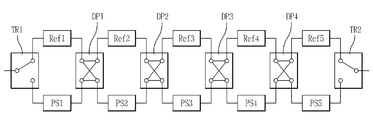
본 발명의 일 실시예에 따른 실시간 스위칭 장치는 도 1에 도시된 것처럼, 제1기준부(Ref1), 제1천이부(PS1), 제1입출력부(TR1), 제2기준부(Ref2), 제2천이부(PS2), 제1포웨이 스위칭부(DP1), 제3기준부(Ref3), 제3천이부(PS3), 제2포웨이 스위칭부(DP2), 제4기준부(Ref4), 제4천이부(PS4), 제3포웨이 스위칭부(DP3), 제5기준부(Ref5), 제5천이부(PS5), 제4포웨이 스위칭부(DP4) 및 제2입출력부(TR2)를 포함하여 구성될 수 있다.As shown in FIG. 1, the real-time switching device according to an exemplary embodiment of the present invention may include a first reference unit Ref1, a first transition unit PS1, a first input / output unit TR1, and a second reference unit Ref2. , The second transition unit PS2, the first four way switching unit DP1, the third reference unit Ref3, the third transition unit PS3, the second four way switching unit DP2, and the fourth reference unit ( Ref4), fourth transition unit PS4, third four-way switching unit DP3, fifth reference unit Ref5, fifth transition unit PS5, fourth four-way switching unit DP4 and second input / output It may be configured to include a portion (TR2).
제1기준부(Ref1)는 인가되는 전기 신호를 전달하며, 제1천이부(PS1)는 인가되는 전기 신호를, 제1기준부(Ref1)에의해서 전달되는 전기 신호의 위상보다 소정의 각도만큼 천이하여 전달한다.The first reference unit Ref1 transmits an applied electric signal, and the first transition unit PS1 transmits the applied electric signal by a predetermined angle from the phase of the electric signal transmitted by the first reference unit Ref1. Transmit and transfer.
제1입출력부(TR1)는 입력되는 전기 신호를 제1기준부(Ref1)나 제1천이부(PS1)로 전달하며, SPDT(Single Pole Double Throw) 스위칭 소자를 이용하여 구성할 수 있다.The first input / output unit TR1 transmits an input electrical signal to the first reference unit Ref1 or the first transition unit PS1, and may be configured by using a single pole double throw (SPDT) switching element.
제2기준부(Ref2)는 제1기준부(Ref1)나 제1천이부(PS1)로부터 인가되는 전기 신호를 전달하며, 제2천이부(PS2)는 제1기준부(Ref1)나 제1천이부(PS1)로부터 인가되는 전기 신호를, 제2기준부(Ref2)에의해서 전달되는 전기 신호의 위상보다 소정의 각도만큼 천이하여 전달하고, 제1포웨이 스위칭부(DP1)는 제1기준부(Ref1)나 제1천이부(PS1)로부터 인가되는 전기 신호를 제2기준부(Ref2)나 제2천이부(PS2)로 전달한다.The second reference unit Ref2 transmits an electrical signal applied from the first reference unit Ref1 or the first transition unit PS1, and the second transition unit PS2 is the first reference unit Ref1 or the first reference unit Ref2. The electrical signal applied from the transition unit PS1 is transferred by a predetermined angle from the phase of the electrical signal transmitted by the second reference unit Ref2, and the first four-way switching unit DP1 transmits the first reference. The electrical signal applied from the unit Ref1 or the first transition unit PS1 is transmitted to the second reference unit Ref2 or the second transition unit PS2.
제3기준부(Ref3)는 제2기준부(Ref2)나 제2천이부(PS2)로부터 인가되는 전기 신호를 전달하며, 제3천이부(PS3)는 제2기준부(Ref2)나 제2천이부(PS2)로부터 인가되는 전기 신호를, 제3기준부(Ref3)에의해서 전달되는 전기 신호의 위상보다 소정의 각도만큼 천이하여 전달하고, 제2포웨이 스위칭부(DP2)는 제2기준부(Ref2)나 제2천이부(PS2)로부터 인가되는 전기 신호를 제3기준부(Ref3)나 제3천이부(PS3)로 전달한다.The third reference unit Ref3 transmits an electrical signal applied from the second reference unit Ref2 or the second transition unit PS2, and the third transition unit PS3 is the second reference unit Ref2 or the second. The electrical signal applied from the transition unit PS2 is transferred by a predetermined angle from the phase of the electrical signal transmitted by the third reference unit Ref3, and the second four-way switching unit DP2 transmits the second reference. The electrical signal applied from the unit Ref2 or the second transition unit PS2 is transmitted to the third reference unit Ref3 or the third transition unit PS3.
제4기준부(Ref4)는 제3기준부(Ref3)나 제3천이부(PS3)로부터 인가되는 전기 신호를 전달하며, 제4천이부(PS4)는 제3기준부(Ref3)나 제3천이부(PS3)로부터 인가되는 전기 신호를, 제4기준부(Ref4)에의해서 전달되는 전기 신호의 위상보다 소정의 각도만큼 천이하여 전달하고, 제3포웨이 스위칭부(DP3)는 제3기준부(Ref3)나 제3천이부(PS3)로부터 인가되는 전기 신호를 제4기준부(Ref4)나 제4천이부(PS4)로 전달한다.The fourth reference unit Ref4 transmits an electrical signal applied from the third reference unit Ref3 or the third transition unit PS3, and the fourth transition unit PS4 is the third reference unit Ref3 or the third. The electrical signal applied from the transition unit PS3 is transferred by a predetermined angle from the phase of the electrical signal transmitted by the fourth reference unit Ref4, and the third four-way switching unit DP3 transmits the third reference. The electrical signal applied from the unit Ref3 or the third transition unit PS3 is transmitted to the fourth reference unit Ref4 or the fourth transition unit PS4.
제5기준부(Ref5)는 제4기준부(Ref4)나 제4천이부(PS4)로부터 인가되는 전기 신호를 전달하며, 제5천이부(PS5)는 제4기준부(Ref4)나 제4천이부(PS4)로부터 인가되는 전기 신호를, 제5기준부(Ref5)에의해서 전달되는 전기 신호의 위상보다 소정의 각도만큼 천이하여 전달하고, 제4포웨이 스위칭부(DP4)는 제4기준부(Ref4)나 제4천이부(PS4)로부터 인가되는 전기 신호를 제5기준부(Ref5)나 제5천이부(PS5)로 전달한다.The fifth reference unit Ref5 transmits an electrical signal applied from the fourth reference unit Ref4 or the fourth transition unit PS4, and the fifth transition unit PS5 is the fourth reference unit Ref4 or the fourth. The electrical signal applied from the transition unit PS4 is transferred by a predetermined angle from the phase of the electrical signal transmitted by the fifth reference unit Ref5, and the fourth four-way switching unit DP4 transmits the fourth reference. The electrical signal applied from the unit Ref4 or the fourth transition unit PS4 is transmitted to the fifth reference unit Ref5 or the fifth transition unit PS5.
제2입출력부(TR2)는 제5기준부(Ref5)나 제5천이부(PS5)로부터 전달되는 전기 신호를 출력하며, SPDT(Single Pole Double Throw) 스위칭 소자를 이용하여 구성할 수 있다.The second input / output unit TR2 outputs an electrical signal transmitted from the fifth reference unit Ref5 or the fifth transition unit PS5, and may be configured using a single pole double throw (SPDT) switching element.
본 발명의 일 실시예에 따른 양방향 분산 위상 천이 장치는 반드시 제1입출력부(TR1)를 통해서 전기 신호가 입력되고 제2입출력부(TR2)를 통해서 전기 신호가 출력될 필요는 없으며, 필요에 따라서 제1입출력부(TR1)를 통해서 전기 신호가 입력되고 제2입출력부(TR2)를 통해서 전기 신호가 출력될 수도 있고, 제2입출력부(TR2)를 통해서 전기 신호가 입력되고 제1입출력부(TR1)를 통해서 전기 신호가 출력될 수도 있다.In the bidirectional distributed phase shifting apparatus according to an embodiment of the present invention, an electrical signal is not necessarily input through the first input / output unit TR1 and an electrical signal is not output through the second input / output unit TR2. An electrical signal may be input through the first input / output unit TR1 and an electrical signal may be output through the second input / output unit TR2, or an electrical signal may be input through the second input / output unit TR2, and the first input / output unit ( An electrical signal may be output through TR1).
도 2를 참조하여, 제1기준부(Ref1)에 대해서 상세하게 설명한다.With reference to FIG. 2, the 1st reference part Ref1 is demonstrated in detail.
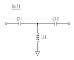
제1기준부(Ref1)는 도 2에 도시된 것처럼, 제11커패시터(C11), 제11커패시터(C11)에 연결되는 제12커패시터(C12) 및 제11커패시터(C11)와 제12커패시터(C12)의 접점과 접지 사이에 연결되는 제11인덕터(L11)를 포함한다.As shown in FIG. 2, the first reference unit Ref1 may include the twelfth capacitor C12, the eleventh capacitor C11, and the eleventh capacitor C11 and the twelfth capacitor C12, which are connected to the eleventh capacitor C11, the eleventh capacitor C11, and the like. It includes an eleventh inductor (L11) connected between the contact point and the ground.
여기에서, 제2기준부 내지 제5기준부(Ref2, Ref3, Ref4, Ref5)는 제1기준부(Ref1)와 동일하게 구성될 수 있다.Here, the second reference unit to the fifth reference unit (Ref2, Ref3, Ref4, Ref5) may be configured in the same way as the first reference unit (Ref1).
도 3을 참조하여, 제1천이부(PS1)에 대해서 상세하게 설명한다.Referring to FIG. 3, the first transition unit PS1 will be described in detail.
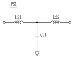
제1천이부(PS1)는 도 3에 도시된 것처럼, 제21인덕터(L21), 제21인덕터(L21)에 연결되는 제22인덕터(L22) 및 제21인덕터(L21)와 제22인덕터(L22)의 접점과 접지 사이에 연결되는 제21커패시터(C21)를 포함하며, 제21인덕터(L21)의 인덕턴스, 제22인덕터(L22)의 인덕턴스 및 제21커패시터(C21)의 커패시턴스를 조정하여 천이되는 위상 각도를 조절할 수 있다.As shown in FIG. 3, the first transition unit PS1 includes the twenty-second inductor L21, the twenty-second inductor L22 connected to the twenty-first inductor L21, and the twenty-first inductor L21 and the twenty-second inductor L22. And a twenty-first capacitor (C21) connected between the contact point and the ground, and the transition to the inductance of the twenty-first inductor (L21), the inductance of the twenty-second inductor (L22) and the capacitance of the twenty-first capacitor (C21) Phase angle can be adjusted.
여기에서, 제2천이부 내지 제5천이부(PS2, PS3, PS4, PS5)는 제1천이부(PS1)와 동일하게 구성될 수 있다.Here, the second to fifth transition parts PS2, PS3, PS4, and PS5 may be configured in the same manner as the first transition part PS1.
도 4를 참조하여, 다른 실시예에 따른 제1기준부(Ref1)에 대해서 상세하게 설명한다.Referring to FIG. 4, the first reference unit Ref1 according to another embodiment will be described in detail.
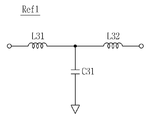
제1기준부(Ref1)는 도 4에 도시된 것처럼, 제31인덕터(L31), 제31인덕터(L31)에 연결되는 제32인덕터(L32) 및 제31인덕터(L31)와 제32인덕터(L32)의 접점과 접지 사이에 연결되는 제31커패시터(C31)를 포함한다.As shown in FIG. 4, the first reference part Ref1 includes a thirty-first inductor L31, a thirty-second inductor L32 connected to the thirty-first inductor L31, a thirty-first inductor L31, and a thirty-second inductor L32. And a thirty-first capacitor C31 connected between the contact point and the ground.
여기에서, 제2기준부 내지 제5기준부(Ref2, Ref3, Ref4, Ref5)는 제1기준부(Ref1)와 동일하게 구성될 수 있다.Here, the second reference unit to the fifth reference unit (Ref2, Ref3, Ref4, Ref5) may be configured in the same way as the first reference unit (Ref1).
도 5를 참조하여 다른 실시예에 따른 제1천이부(PS1)에 대해서 자세하게 설명한다.The first transition unit PS1 according to another embodiment will be described in detail with reference to FIG. 5.
제1천이부(PS1)는 도 5에 도시된 것처럼, 제41커패시터(C41), 제41커패시터(C41)에 연결되는 제42커패시터(C42) 및 제41커패시터(C41)와 제42커패시터(C42)의 접점과 접지 사이에 연결되는 제41인덕터(L41)를 포함하며, 제41커패시터(C41)의 커패시턴스, 제42커패시터(C42)의 커패시턴스 및 제41인덕터(L41)의 인덕턴스를 조정하여 천이되는 위상 각도를 조절할 수 있다.As illustrated in FIG. 5, the first transition unit PS1 includes the forty-first capacitor C42, the forty-first capacitor C42, and the forty-first capacitor C41 and the forty-second capacitor C42 connected to the forty-first capacitor C41 and the forty-first capacitor C41. And a forty-first inductor L41 connected between the contact point and the ground, and are adjusted by adjusting the capacitance of the forty-first capacitor C41, the capacitance of the forty-second capacitor C42, and the inductance of the forty-first inductor L41. Phase angle can be adjusted.
여기에서, 제2천이부 내지 제5천이부(PS2, PS3, PS4, PS5)는 제1천이부(PS1)와 동일하게 구성될 수 있다.Here, the second to fifth transition parts PS2, PS3, PS4, and PS5 may be configured in the same manner as the first transition part PS1.
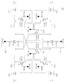
도 6을 참조하여, 제1포웨이 스위칭부(DP1)에 대해서 상세하게 설명한다.Referring to FIG. 6, the first four-way switching unit DP1 will be described in detail.
제1포웨이 스위칭부(DP1)는 제11스위칭부(1110), 제12스위칭부(1120), 제21스위칭부(1210) 및 제22스위칭부(1220)를 포함한다.The first four-way switching unit DP1 includes an
제11스위칭부(1110)는 제11포트(P11)와 제21포트(P21)사이에 연결되는 제1모스트랜지스터(M1)를 포함하며, 제1모스트랜지스터(M1)가 턴온되는 경우에 제11포트(P11)와 제21포트(P21)사이에 전기 신호를 전달한다.The
여기에서, 저항(R1111)은 바이어스 전압(Bias111)을 전달하기 위한 것이며, 저항(R1112)은 누설 전류를 억제하기 위한 것이다.Here, the resistor R1111 is for delivering the bias voltage Bias111, and the resistor R1112 is for suppressing the leakage current.
제12스위칭부(1120)는 제11포트(P11)와 제22포트(P22)사이에 연결되는 제2모스트랜지스터(M2)를 포함하며, 제2모스트랜지스터(M2)가 턴온되는 경우에 제11포트(P11)와 제22포트(P22)사이에 전기 신호를 전달한다.The
여기에서, 저항(R1121)은 바이어스 전압(Bias112)을 전달하기 위한 것이며, 저항(R1122)은 누설 전류를 억제하기 위한 것이다.Here, the resistor R1121 is for delivering the bias voltage Bis112, and the resistor R1122 is for suppressing the leakage current.
제21스위칭부(1210)는 제12포트(P12)와 상기 제21포트(P21)사이에 연결되는 제3모스트랜지스터(M3)를 포함하며, 제3모스트랜지스터(M3)가 턴온되는 경우에 제12포트(P12)와 제21포트(P21)사이에 전기 신호를 전달한다.The twenty-
여기에서, 저항(R1211)은 바이어스 전압(Bias121)을 전달하기 위한 것이며, 저항(R1212)은 누설 전류를 억제하기 위한 것이다.Here, the resistor R1211 is for delivering the bias voltage Bias121, and the resistor R1212 is for suppressing the leakage current.
제22스위칭부(1220)는 제12포트(P12)와 제22포트(P22)사이에 연결되는 제4모스트랜지스터(M4)를 포함하며, 제4모스트랜지스터(M4)가 턴온되는 경우에 제12포트(P12)와 제22포트(P22)사이에 전기 신호를 전달한다.The twenty-
여기에서, 저항(R1221)은 바이어스 전압(Bias122)을 전달하기 위한 것이며, 저항(R1222)은 누설 전류를 억제하기 위한 것이다.Here, the resistor R1221 is for delivering the bias voltage Bias122, and the resistor R1222 is for suppressing the leakage current.
한편, 제1모스트랜지스터(M1)의 드레인과 제2모스트랜지스터(M2)의 드레인에 연결되며, 제4모스트랜지스터(M4)가 제12포트(P12)와 제22포트(P22)사이에 전기 신호를 전달하는 경우나 제3모스트랜지스터(M3)가 제21포트(P21)와 제12포트(P12)사이에 전기 신호를 전달하는 경우에, 제1모스트랜지스터(M1)의 드레인과 접지를 연결시키거나 제2모스트랜지스터(M2)의 드레인과 접지를 연결시키는 제11접지부(2110)가 더 포함될 수 있으며, 이러한 제11접지부(2110)는 제5모스트랜지스터(M5)를 포함할 수 있다.Meanwhile, the drain of the first MOS transistor M1 and the drain of the second MOS transistor M2 are connected, and the fourth MOS transistor M4 is an electrical signal between the twelfth port P12 and the twenty-second port P22. In the case of transmitting the or when the third MOS transistor M3 transmits an electrical signal between the twenty-first port P21 and the twelfth port P12, the drain and ground of the first MOS transistor M1 may be connected. Alternatively, an
여기에서, 저항(R2111)은 바이어스 전압(Bias211)을 전달하기 위한 것이며, 저항(R2112)은 누설 전류를 억제하기 위한 것이다.Here, the resistor R2111 is for transmitting the bias voltage Bis211 and the resistor R2112 is for suppressing the leakage current.
상술한 것처럼, 제4모스트랜지스터(M4)가 제12포트(P12)와 제22포트(P22)사이에 전기 신호를 전달하는 경우나 제3모스트랜지스터(M3)가 제21포트(P21)와 제12포트(P12)사이에 전기 신호를 전달하는 경우에, 제11접지부(2110)가 제1모스트랜지스터(M1)의 드레인과 접지를 연결시키거나 제2모스트랜지스터(M2)의 드레인과 접지를 연결시킴으로써, 제4모스트랜지스터(M4)가 제12포트(P12)와 제22포트(P22)사이에 전기 신호를 전달하는 경우나 제3모스트랜지스터(M3)가 제21포트(P21)와 제12포트(P12)사이에 전기 신호를 전달하는 경우에, 전기 신호가 제12포트(P12)와 제22포트(P22)사이나 제21포트(P21)와 제12포트(P12)사이에서 누설되는 것을 효과적으로 억제할 수 있다.As described above, when the fourth MOS transistor M4 transmits an electrical signal between the twelfth port P12 and the twenty-second port P22, or when the third MOS transistor M3 is connected to the twenty-first port P21 and the first port. When the electrical signal is transmitted between the twelve ports P12, the
또한, 제4모스트랜지스터(M4)의 드레인과 제3모스트랜지스터(M3)의 소스에 연결되며, 제1모스트랜지스터(M1)가 제11포트(P11)와 제21포트(P21)사이에 전기 신호를 전달하는 경우나 제2모스트랜지스터(M2)가 제11포트(P11)와 제22포트(P22)사이에 전기 신호를 전달하는 경우에, 제4모스트랜지스터(M4)의 드레인과 접지를 연결시키거나 제3모스트랜지스터(M3)의 소스와 접지를 연결시키는 제12접지부(2120)가 더 포함될 수 있으며, 이러한 제12접지부(2120)는 제6모스트랜지스터(M6)를 포함할 수 있다.In addition, the drain of the fourth MOS transistor M4 and the source of the third MOS transistor M3 are connected, and the first MOS transistor M1 is an electrical signal between the eleventh port P11 and the twenty-first port P21. In this case, the second MOS transistor M2 transmits an electrical signal between the eleventh port P11 and the twenty-second port P22, and connects the drain and ground of the fourth MOS transistor M4. Alternatively, a
여기에서, 저항(R2121)은 바이어스 전압(Bias212)을 전달하기 위한 것이며, 저항(R2122)은 누설 전류를 억제하기 위한 것이다.Here, the resistor R2121 is for transmitting the bias voltage Bis212 and the resistor R2122 is for suppressing the leakage current.
상술한 것처럼, 제1모스트랜지스터(M1)가 제11포트(P11)와 제21포트(P21)사이에 전기 신호를 전달하는 경우나 제2모스트랜지스터(M2)가 제11포트(P11)와 제22포트(P22)사이에 전기 신호를 전달하는 경우에, 제12접지부(2120)가 제4모스트랜지스터(M4)의 드레인과 접지를 연결시키거나 제3모스트랜지스터(M3)의 소스와 접지를 연결시킴으로써, 제1모스트랜지스터(M1)가 제11포트(P11)와 제21포트(P21)사이에 전기 신호를 전달하는 경우나 제2모스트랜지스터(M2)가 제11포트(P11)와 제22포트(P22)사이에 전기 신호를 전달하는 경우에, 전기 신호가 제11포트(P11)와 제21포트(P21)사이나 제11포트(P11)와 제22포트(P22)사이에서 누설되는 것을 효과적으로 억제할 수 있다.As described above, when the first MOS transistor M1 transmits an electrical signal between the eleventh port P11 and the twenty-first port P21, or the second MOS transistor M2 is connected to the eleventh port P11 and the first port. When the electrical signal is transferred between the 22 ports P22, the
또한, 제3모스트랜지스터(M3)의 드레인과 제1모스트랜지스터(M1)의 소스에 연결되며, 제4모스트랜지스터(M4)가 제12포트(P12)와 제22포트(P22)사이에 전기 신호를 전달하는 경우나 제2모스트랜지스터(M2)가 제11포트(P11)와 제22포트(P22)사이에 전기 신호를 전달하는 경우에, 제3모스트랜지스터(M3)의 드레인과 접지를 연결시키거나 제1모스트랜지스터(M1)의 소스와 접지를 연결시키는 제21접지부(2210)가 더 포함될 수 있으며, 이러한 제21접지부(2210)는 제7모스트랜지스터(M7)를 포함할 수 있다.In addition, the drain of the third MOS transistor M3 and the source of the first MOS transistor M1 are connected, and the fourth MOS transistor M4 is an electrical signal between the twelfth port P12 and the twenty-second port P22. When the second MOS transistor M2 transmits an electrical signal between the eleventh port P11 and the twenty-second port P22, the drain and the ground of the third MOS transistor M3 are connected to each other. Alternatively, a twenty-
여기에서, 저항(R2211)은 바이어스 전압(Bias221)을 전달하기 위한 것이며, 저항(R2212)은 누설 전류를 억제하기 위한 것이다.Here, the resistor R2211 is for transmitting the bias voltage Bias221, and the resistor R2212 is for suppressing the leakage current.
상술한 것처럼, 제4모스트랜지스터(M4)가 제12포트(P12)와 제22포트(P22)사이에 전기 신호를 전달하는 경우나 제2모스트랜지스터(M2)가 제11포트(P11)와 제22포트(P22)사이에 전기 신호를 전달하는 경우에, 제21접지부(2210)가 제3모스트랜지스터(M3)의 드레인과 접지를 연결시키거나 제1모스트랜지스터(M1)의 소스와 접지를 연결시킴으로써, 제4모스트랜지스터(M4)가 제12포트(P12)와 제22포트(P22)사이에 전기 신호를 전달하는 경우나 제2모스트랜지스터(M2)가 제11포트(P11)와 제22포트(P22)사이에 전기 신호를 전달하는 경우에, 전기 신호가 제12포트(P12)와 제22포트(P22)사이나 제11포트(P11)와 제22포트(P22)사이에서 누설되는 것을 효과적으로 억제할 수 있다.As described above, when the fourth MOS transistor M4 transmits an electrical signal between the twelfth port P12 and the twenty-second port P22, or the second MOS transistor M2 is connected to the eleventh port P11 and the eleventh port P11. When the electrical signal is transferred between the 22 ports P22, the twenty-
또한, 제4모스트랜지스터(M4)의 소스와 제2모스트랜지스터(M2)의 소스에 연결되며, 제1모스트랜지스터(M1)가 제11포트(P11)와 제21포트(P21)사이에 전기 신호를 전달하는 경우나 제3모스트랜지스터(M3)가 제12포트(P12)와 제21포트(P21)사이에 전기 신호를 전달하는 경우에, 제4모스트랜지스터(M4)의 소스와 접지를 연결시키거나 제2모스트랜지스터(M2)의 소스와 접지를 연결시키는 제22접지부(2220)가 더 포함될 수 있으며, 이러한 제22접지부(2220)는 제8모스트랜지스터(M8)를 포함할 수 있다.In addition, the source of the fourth MOS transistor M4 and the source of the second MOS transistor M2 are connected, and the first MOS transistor M1 is an electrical signal between the eleventh port P11 and the twenty-first port P21. In the case of transmitting a signal or when the third MOS transistor M3 transmits an electrical signal between the twelfth port P12 and the twenty-first port P21, the source and the ground of the fourth MOS transistor M4 are connected. Alternatively, a twenty-
여기에서, 저항(R2221)은 바이어스 전압(Bias222)을 전달하기 위한 것이며, 저항(R2222)은 누설 전류를 억제하기 위한 것이다.Here, the resistor R2221 is for delivering the bias voltage Bis222, and the resistor R2222 is for suppressing the leakage current.
상술한 것처럼, 제1모스트랜지스터(M1)가 제11포트(P11)와 제21포트(P21)사이에 전기 신호를 전달하는 경우나 제3모스트랜지스터(M3)가 제12포트(P12)와 제21포트(P21)사이에 전기 신호를 전달하는 경우에, 제22접지부(2220)가 제4모스트랜지스터(M4)의 소스와 접지를 연결시키거나 제2모스트랜지스터(M2)의 소스와 접지를 연결시킴으로써, 제1모스트랜지스터(M1)가 제11포트(P11)와 제21포트(P21)사이에 전기 신호를 전달하는 경우나 제3모스트랜지스터(M3)가 제12포트(P12)와 제21포트(P21)사이에 전기 신호를 전달하는 경우에, 전기 신호가 제11포트(P11)와 제21포트(P21)사이나 제12포트(P12)와 제21포트(P21)사이에서 누설되는 것을 효과적으로 억제할 수 있다.As described above, when the first MOS transistor M1 transmits an electrical signal between the eleventh port P11 and the twenty-first port P21, or the third MOS transistor M3 is connected to the twelfth port P12 and the first port. When the electrical signal is transferred between the 21 ports P21, the
한편, 제11포트(P11)와 제11스위칭부(1110) 및 제12스위칭부(1120)사이에 배치되어, 제11포트(P11)의 임피던스를 조절하는 제11임피던스부(3110)가 더 포함될 수 있으며, 구체적으로, 제11임피던스부(3110)는 제1인덕터(L1)를 포함할 수 있다.Meanwhile, an
이러한 제11임피던스부(3110)는 제1모스트랜지스터(M1)나 제2모스트랜지스터(M2)에 의해서 발생되는 기생 커패시턴스를 상쇄시킬 수 있다.The
또한, 제12포트(P12)와 제21스위칭부(1210) 및 제22스위칭부(1220)사이에 배치되어, 상기 제12포트(P12)의 임피던스를 조절하는 제12임피던스부(3120)가 더 포함될 수 있으며, 구체적으로, 제12임피던스부(3120)는 제2인덕터(L2)를 포함할 수 있다.In addition, a
이러한 제12임피던스부(3120)는 제4모스트랜지스터(M4)나 제3모스트랜지스터(M3)에 의해서 발생되는 기생 커패시턴스를 상쇄시킬 수 있다.The
또한, 제21포트(P21)와 제11스위칭부(1110) 및 제21스위칭부(1210)사이에 배치되어, 제21포트(P21)의 임피던스를 조절하는 제21임피던스부(3210)가 더 포함될 수 있으며, 구체적으로, 제21임피던스부(3210)는 제3인덕터(L3)를 포함할 수 있다.In addition, a twenty-
이러한 제21임피던스부(3210)는 제1모스트랜지스터(M1)나 제3모스트랜지스터(M3)에 의해서 발생되는 기생 커패시턴스를 상쇄시킬 수 있다.The twenty-
또한, 제22포트(P22)와 제22스위칭부(1220) 및 제12스위칭부(1120)사이에 배치되어, 제22포트(P22)의 임피던스를 조절하는 제22임피던스부(3220)가 더 포함될 수 있으며, 구체적으로, 제22임피던스부(3220)는 제4인덕터(L4)를 포함할 수 있다.Further, a twenty-
이러한 제22임피던스부(3220)는 제4모스트랜지스터(M4)나 제2모스트랜지스터(M2)에 의해서 발생되는 기생 커패시턴스를 상쇄시킬 수 있다.The
여기에서, 제2포웨이 스위칭부(DP2) 내지 제4포웨이 스위칭부(DP2, DP3, DP4)는 제1포웨이 스위칭부(DP1)와 동일하게 구성하는 것이 바람직하다.Here, the second four-way switching unit DP2 to fourth four-way switching unit DP2, DP3, DP4 may be configured in the same manner as the first four-way switching unit DP1.
한편, 본 발명의 일 실시예에 따른 양방향 분산 위상 천이 장치는 반드시 제1기준부 내지 제5기준부(Ref1,Ref2, Ref3, Ref4, Ref5)나 제1천이부 내지 제5천이부(PS1, PS2, PS3, PS4, PS5)를 포함할 필요는 없으며, 필요에 따라서 지연 회로를 2 단계로 구성하거나 3 단계로 구성하거나 4 단계로 구성할 수 있다.On the other hand, in the bidirectional distributed phase shifting apparatus according to an embodiment of the present invention, the first reference unit to the fifth reference unit (Ref1, Ref2, Ref3, Ref4, Ref5) or the first transition unit to the fifth transition unit (PS1, It is not necessary to include PS2, PS3, PS4, PS5, and the delay circuit can be configured in two stages, three stages, or four stages as necessary.
예를 들어, 지연 회로가 2 단계로 구성될 경우에는 제1입출력부(TR1), 제1기준부(Ref1), 제1천이부(PS1), 제2기준부(Ref2), 제2천이부(PS2), 제1포웨이 스위칭부(DP1) 및 제2입출력부(TR2)를 포함하여 구성될 수 있으며, 지연 회로가 3 단계로 구성될 경우에는 제1입출력부(TR1), 제1기준부(Ref1), 제1천이부(PS1), 제2기준부(Ref2), 제2천이부(PS2), 제1포웨이 스위칭부(DP1), 제3기준부(Ref3), 제3천이부(PS3), 제2포웨이 스위칭부(DP2) 및 제2입출력부(TR2)를 포함하여 구성될 수 있고, 지연 회로가 4 단계로 구성될 경우에는 제1입출력부(TR1), 제1기준부(Ref1), 제1천이부(PS1), 제2기준부(Ref2), 제2천이부(PS2), 제1포웨이 스위칭부(DP1), 제3기준부(Ref3), 제3천이부(PS3), 제2포웨이 스위칭부(DP2), 제4기준부(Ref4), 제4천이부(PS4), 제3포웨이 스위칭부(DP3) 및 제2입출력부(TR2)를 포함하여 구성될 수 있다.
For example, when the delay circuit is configured in two stages, the first input / output unit TR1, the first reference unit Ref1, the first transition unit PS1, the second reference unit Ref2, and the second transition unit (PS2), the first four-way switching unit (DP1) and the second input and output unit (TR2) can be configured, if the delay circuit is composed of three stages, the first input and output unit (TR1), the first reference Ref1, first transition part PS1, second reference part Ref2, second transition part PS2, first poway switching part DP1, third reference part Ref3, third transition Unit PS3, the second four-way switching unit DP2, and the second input / output unit TR2, and the first input / output unit TR1 and the first input / output unit when the delay circuit is configured in four stages. Reference part Ref1, first transition part PS1, second reference part Ref2, second transition part PS2, first poway switching part DP1, third reference part Ref3, third The transition unit PS3, the second four-way switching unit DP2, the fourth reference unit Ref4, the fourth transition unit PS4, the third four-way switching unit DP3, and the second input / output unit TR2 It can be configured to include.
이상, 본 발명을 본 발명의 원리를 예시하기 위한 바람직한 실시예와 관련하여 설명하고 도시하였지만, 본 발명은 그와 같이 도시되고 설명된 그대로의 구성 및 작용으로 한정되는 것이 아니다. While the present invention has been particularly shown and described with reference to exemplary embodiments thereof, it is to be understood that the invention is not limited to the disclosed exemplary embodiments.
오히려, 첨부된 청구범위의 사상 및 범주를 일탈함이 없이 본 발명에 대한 다수의 변경 및 수정이 가능함을 당업자들은 잘 이해할 수 있을 것이다.Rather, it will be apparent to those skilled in the art that many changes and modifications to the present invention are possible without departing from the spirit and scope of the appended claims.
따라서, 그러한 모든 적절한 변경 및 수정과 균등물들도 본 발명의 범위에 속하는 것으로 간주되어야 할 것이다.
Accordingly, all such appropriate modifications and changes, and equivalents thereof, should be regarded as within the scope of the present invention.
Claims (16)
인가되는 전기 신호를, 상기 제1기준부에의해서 전달되는 전기 신호의 위상보다 소정의 각도만큼 천이하여 전달하는 제1천이부;
입력되는 전기 신호를 상기 제1기준부나 상기 제1천이부로 전달하는 제1입출력부;
상기 제1기준부나 상기 제1천이부로부터 인가되는 전기 신호를 전달하는 제2기준부;
상기 제1기준부나 상기 제1천이부로부터 인가되는 전기 신호를, 상기 제2기준부에의해서 전달되는 전기 신호의 위상보다 소정의 각도만큼 천이하여 전달하는 제2천이부;
상기 제1기준부나 상기 제1천이부로부터 인가되는 전기 신호를 상기 제2기준부나 상기 제2천이부로 전달하는 제1포웨이 스위칭부; 및
상기 제2기준부나 상기 제2천이부로부터 인가되는 전기 신호를 출력하는 제2입출력부를 포함하는 양방향 분산 위상 천이 장치.
A first reference unit for transmitting an applied electric signal;
A first transition unit which transfers the applied electric signal by a predetermined angle from a phase of the electric signal transmitted by the first reference unit;
A first input / output unit configured to transfer an input electrical signal to the first reference unit or the first transition unit;
A second reference unit configured to transfer an electrical signal applied from the first reference unit or the first transition unit;
A second transition unit which transfers the electrical signal applied from the first reference unit or the first transition unit by a predetermined angle from the phase of the electrical signal transmitted by the second reference unit;
A first four-way switching unit transferring an electrical signal applied from the first reference unit or the first transition unit to the second reference unit or the second transition unit; And
And a second input / output unit configured to output an electrical signal applied from the second reference unit or the second transition unit.
상기 제1기준부 또는 상기 제2기준부 중 어느 하나는
제11커패시터;
상기 제11커패시터에 연결되는 제12커패시터; 및
상기 제11커패시터와 상기 제12커패시터의 접점과 접지 사이에 연결되는 제11인덕터를 포함하는 것을 특징으로 하는 양방향 분산 위상 천이 장치.
The method of claim 1,
Any one of the first reference unit or the second reference unit
An eleventh capacitor;
A twelfth capacitor connected to the eleventh capacitor; And
And an eleventh inductor connected between the contact point of the eleventh capacitor and the twelfth capacitor and the ground.
상기 제1천이부 또는 상기 제2천이부 중 어느 하나는
제21인덕터;
상기 제21인덕터에 연결되는 제22인덕터; 및
상기 제21인덕터와 상기 제22인덕터의 접점과 접지 사이에 연결되는 제21커패시터를 포함하는 것을 특징으로 하는 양방향 분산 위상 천이 장치.
The method of claim 1,
Any one of the first transition part or the second transition part
A twenty-first inductor;
A twenty-second inductor connected to the twenty-first inductor; And
And a twenty-first capacitor connected between the contact point of the twenty-first inductor and the twenty-second inductor and a ground.
상기 제1기준부 또는 상기 제2기준부 중 어느 하나는
제31인덕터;
상기 제31인덕터에 연결되는 제32인덕터; 및
상기 제31인덕터와 상기 제32인덕터의 접점과 접지 사이에 연결되는 제31커패시터를 포함하는 것을 특징으로 하는 양방향 분산 위상 천이 장치.
The method of claim 1,
Any one of the first reference unit or the second reference unit
Thirty-one inductors;
A thirty-second inductor connected to the thirty-first inductor; And
And a thirty-one capacitor connected between the contact point of the thirty-first inductor and the thirty-second inductor and a ground.
상기 제1천이부 또는 상기 제2천이부 중 어느 하나는
제41커패시터;
상기 제41커패시터에 연결되는 제42커패시터; 및
상기 제41커패시터와 상기 제42커패시터의 접점과 접지 사이에 연결되는 제41인덕터를 포함하는 것을 특징으로 하는 양방향 분산 위상 천이 장치.
The method of claim 1,
Any one of the first transition part or the second transition part
A 41 th capacitor;
A 42nd capacitor connected to the 41st capacitor; And
And a forty-one inductor connected between the contact point of the forty-first capacitor and the forty-second capacitor and the ground.
상기 제1포웨이 스위칭부는
제11포트와 제21포트사이에 연결되는 제1모스트랜지스터를 포함하며, 상기 제1모스트랜지스터가 턴온되는 경우에 상기 제11포트와 상기 제21포트사이에 전기 신호를 전달하는 제11스위칭부;
상기 제11포트와 제22포트사이에 연결되는 제2모스트랜지스터를 포함하며, 상기 제2모스트랜지스터가 턴온되는 경우에 상기 제11포트와 상기 제22포트사이에 전기 신호를 전달하는 제12스위칭부;
제12포트와 상기 제21포트사이에 연결되는 제3모스트랜지스터를 포함하며, 상기 제3모스트랜지스터가 턴온되는 경우에 상기 제12포트와 상기 제21포트사이에 전기 신호를 전달하는 제21스위칭부; 및
상기 제12포트와 상기 제22포트사이에 연결되는 제4모스트랜지스터를 포함하며, 상기 제4모스트랜지스터가 턴온되는 경우에 상기 제12포트와 상기 제22포트사이에 전기 신호를 전달하는 제22스위칭부를 포함하는 것을 특징으로 하는 양방향 분산 위상 천이 장치.
The method of claim 1,
The first four-way switching unit
An eleventh switching unit including a first MOS transistor connected between the eleventh port and the twenty-first port, and transferring an electrical signal between the eleventh port and the twenty-first port when the first MOS transistor is turned on;
A twelfth switching part including a second MOS transistor connected between the eleventh port and the twenty-second port and transferring an electrical signal between the eleventh port and the twenty-second port when the second MOS transistor is turned on; ;
And a third MOS transistor connected between the twelfth port and the twenty-first port, wherein the twenty-first switching unit transfers an electrical signal between the twelfth port and the twenty-first port when the third MOS transistor is turned on. ; And
A twenty-second switching device comprising a fourth MOS transistor connected between the twelfth port and the twenty-second port, and transferring an electrical signal between the twelfth port and the twenty-second port when the fourth morph transistor is turned on; Bidirectional distributed phase shifting device, characterized in that it comprises a portion.
상기 제1포웨이 스위칭부는 상기 제1모스트랜지스터의 드레인과 상기 제2모스트랜지스터의 드레인에 연결되며 상기 제4모스트랜지스터가 상기 제12포트와 상기 제22포트사이에 전기 신호를 전달하는 경우나 상기 제3모스트랜지스터가 상기 제21포트와 상기 제12포트사이에 전기 신호를 전달하는 경우에 상기 제1모스트랜지스터의 드레인과 접지를 연결시키거나 상기 제2모스트랜지스터의 드레인과 접지를 연결시키는 제11접지부나, 상기 제4모스트랜지스터의 드레인과 상기 제3모스트랜지스터의 소스에 연결되며 상기 제1모스트랜지스터가 상기 제11포트와 상기 제21포트사이에 전기 신호를 전달하는 경우나 상기 제2모스트랜지스터가 상기 제11포트와 상기 제22포트사이에 전기 신호를 전달하는 경우에 상기 제4모스트랜지스터의 드레인과 접지를 연결시키거나 상기 제3모스트랜지스터의 소스와 접지를 연결시키는 제12접지부나, 상기 제3모스트랜지스터의 드레인과 상기 제1모스트랜지스터의 소스에 연결되며 상기 제4모스트랜지스터가 상기 제12포트와 상기 제22포트사이에 전기 신호를 전달하는 경우나 상기 제2모스트랜지스터가 상기 제11포트와 상기 제22포트사이에 전기 신호를 전달하는 경우에 상기 제3모스트랜지스터의 드레인과 접지를 연결시키거나 상기 제1모스트랜지스터의 소스와 접지를 연결시키는 제21접지부나, 상기 제4모스트랜지스터의 소스와 상기 제2모스트랜지스터의 소스에 연결되며 상기 제1모스트랜지스터가 상기 제11포트와 상기 제21포트사이에 전기 신호를 전달하는 경우나 상기 제3모스트랜지스터가 상기 제12포트와 상기 제21포트사이에 전기 신호를 전달하는 경우에 상기 제4모스트랜지스터의 소스와 접지를 연결시키거나 상기 제2모스트랜지스터의 소스와 접지를 연결시키는 제22접지부를 더 포함하는 것을 특징으로 양방향 분산 위상 천이 장치.
The method according to claim 6,
The first four-way switching unit is connected to the drain of the first MOS transistor and the drain of the second MOS transistor and the fourth MOS transistor transfers an electrical signal between the twelfth port and the twenty-second port or the An eleventh connecting the drain and the ground of the first MOS transistor or the drain and the ground of the second MOS transistor when the third MOS transistor transfers an electrical signal between the twenty-first port and the twelfth port; A ground portion, a drain of the fourth MOS transistor and a source of the third MOS transistor, wherein the first MOS transistor transfers an electrical signal between the eleventh port and the twenty-first port, or the second MOS transistor. Is connected to the ground and the drain of the fourth MOS transistor when the electrical signal is transferred between the eleventh port and the twenty-second port. A twelfth ground portion that connects or connects the source of the third MOS transistor and ground, or the drain of the third MOS transistor and the source of the first MOS transistor, and the fourth MOS transistor is connected to the twelfth port and the first MOS transistor. When the electrical signal is transferred between the 22 ports or when the second MOS transistor transmits the electrical signal between the eleventh port and the twenty-second port, the drain and ground of the third MOS transistor are connected to each other. A twenty-first ground portion connecting a source of the first MOS transistor and a ground; or a source of the fourth MOS transistor and a source of the second MOS transistor, wherein the first MOS transistor is connected between the eleventh port and the twenty-first port. The fourth when the electrical signal is transmitted or when the third MOS transistor transfers the electrical signal between the twelfth port and the twenty-first port. 22 ground bidirectional dispersion phase, characterized in that it further comprises a shift device for connecting the source to ground and the switch transistor, or connect the source and ground of the second MOS transistor.
상기 제1포웨이 스위칭부는 상기 제11포트와 상기 제11스위칭부 및 상기 제12스위칭부사이에 배치되어 상기 제11포트의 임피던스를 조절하는 제11임피던스부나, 상기 제12포트와 상기 제21스위칭부 및 상기 제22스위칭부사이에 배치되어 상기 제12포트의 임피던스를 조절하는 제12임피던스부나, 상기 제21포트와 상기 제11스위칭부 및 상기 제21스위칭부사이에 배치되어 상기 제21포트의 임피던스를 조절하는 제21임피던스부나, 상기 제22포트와 상기 제22스위칭부 및 상기 제12스위칭부사이에 배치되어 상기 제22포트의 임피던스를 조절하는 제22임피던스부를 더 포함하는 것을 특징으로 양방향 분산 위상 천이 장치.
The method according to claim 6,
The first four-way switching unit may be disposed between the eleventh port, the eleventh switching unit, and the twelfth switching unit to adjust an impedance of the eleventh port, or the twelfth port and the twenty-first switching unit And a twelfth impedance part disposed between the twenty-second switching part to adjust the impedance of the twelfth port, or between the twenty-first port and the eleventh switching part and the twenty-first switching part to adjust the impedance of the twenty-first port. And a twenty-first impedance unit or a twenty-second impedance unit disposed between the twenty-second port, the twenty-second switching unit, and the twelfth switching unit to adjust the impedance of the twenty-second port.
인가되는 전기 신호를, 상기 제1기준부에의해서 전달되는 전기 신호의 위상보다 소정의 각도만큼 천이하여 전달하는 제1천이부;
입력되는 전기 신호를 상기 제1기준부나 상기 제1천이부로 전달하는 제1입출력부;
상기 제1기준부나 상기 제1천이부로부터 인가되는 전기 신호를 전달하는 제2기준부;
상기 제1기준부나 상기 제1천이부로부터 인가되는 전기 신호를, 상기 제2기준부에의해서 전달되는 전기 신호의 위상보다 소정의 각도만큼 천이하여 전달하는 제2천이부;
상기 제1기준부나 상기 제1천이부로부터 인가되는 전기 신호를 상기 제2기준부나 상기 제2천이부로 전달하는 제1포웨이 스위칭부;
상기 제2기준부나 상기 제2천이부로부터 인가되는 전기 신호를 전달하는 제3기준부;
상기 제2기준부나 상기 제2천이부로부터 인가되는 전기 신호를, 상기 제3기준부에의해서 전달되는 전기 신호의 위상보다 소정의 각도만큼 천이하여 전달하는 제3천이부;
상기 제2기준부나 상기 제2천이부로부터 인가되는 전기 신호를 상기 제3기준부나 상기 제3천이부로 전달하는 제2포웨이 스위칭부;
상기 제3기준부나 상기 제3천이부로부터 인가되는 전기 신호를 전달하는 제4기준부;
상기 제3기준부나 상기 제3천이부로부터 인가되는 전기 신호를, 상기 제4기준부에의해서 전달되는 전기 신호의 위상보다 소정의 각도만큼 천이하여 전달하는 제4천이부;
상기 제3기준부나 상기 제3천이부로부터 인가되는 전기 신호를 상기 제4기준부나 상기 제4천이부로 전달하는 제3포웨이 스위칭부;
상기 제4기준부나 상기 제4천이부로부터 인가되는 전기 신호를 전달하는 제5기준부;
상기 제4기준부나 상기 제4천이부로부터 인가되는 전기 신호를, 상기 제5기준부에의해서 전달되는 전기 신호의 위상보다 소정의 각도만큼 천이하여 전달하는 제5천이부;
상기 제4기준부나 상기 제4천이부로부터 인가되는 전기 신호를 상기 제5기준부나 상기 제5천이부로 전달하는 제4포웨이 스위칭부; 및
상기 제5기준부나 상기 제5천이부로부터 인가되는 전기 신호를 출력하는 제2입출력부를 포함하는 양방향 분산 위상 천이 장치.
A first reference unit for transmitting an applied electric signal;
A first transition unit which transfers the applied electric signal by a predetermined angle from a phase of the electric signal transmitted by the first reference unit;
A first input / output unit configured to transfer an input electrical signal to the first reference unit or the first transition unit;
A second reference unit configured to transfer an electrical signal applied from the first reference unit or the first transition unit;
A second transition unit which transfers the electrical signal applied from the first reference unit or the first transition unit by a predetermined angle from the phase of the electrical signal transmitted by the second reference unit;
A first four-way switching unit transferring an electrical signal applied from the first reference unit or the first transition unit to the second reference unit or the second transition unit;
A third reference unit which transmits an electric signal applied from the second reference unit or the second transition unit;
A third transition unit which transfers the electrical signal applied from the second reference unit or the second transition unit by a predetermined angle from the phase of the electrical signal transmitted by the third reference unit;
A second four-way switching unit transferring an electrical signal applied from the second reference unit or the second transition unit to the third reference unit or the third transition unit;
A fourth reference unit which transmits an electric signal applied from the third reference unit or the third transition unit;
A fourth transition unit which transfers the electrical signal applied from the third reference unit or the third transition unit by a predetermined angle from the phase of the electrical signal transmitted by the fourth reference unit;
A third four-way switching unit transferring an electrical signal applied from the third reference unit or the third transition unit to the fourth reference unit or the fourth transition unit;
A fifth reference unit configured to transfer an electrical signal applied from the fourth reference unit or the fourth transition unit;
A fifth transition unit which transfers the electrical signal applied from the fourth reference unit or the fourth transition unit by a predetermined angle from the phase of the electrical signal transmitted by the fifth reference unit;
A fourth four-way switching unit transferring an electrical signal applied from the fourth reference unit or the fourth transition unit to the fifth reference unit or the fifth transition unit; And
And a second input / output unit configured to output an electrical signal applied from the fifth reference unit or the fifth transition unit.
상기 제1기준부 내지 제5기준부 중 어느 하나는
제11커패시터;
상기 제11커패시터에 연결되는 제12커패시터; 및
상기 제11커패시터와 상기 제12커패시터의 접점과 접지 사이에 연결되는 제11인덕터를 포함하는 것을 특징으로 하는 양방향 분산 위상 천이 장치.
The method of claim 9,
Any one of the first reference unit to the fifth reference unit
An eleventh capacitor;
A twelfth capacitor connected to the eleventh capacitor; And
And an eleventh inductor connected between the contact point of the eleventh capacitor and the twelfth capacitor and the ground.
상기 제1천이부 내지 제5천이부 중 어느 하나는
제21인덕터;
상기 제21인덕터에 연결되는 제22인덕터; 및
상기 제21인덕터와 상기 제22인덕터의 접점과 접지 사이에 연결되는 제21커패시터를 포함하는 것을 특징으로 하는 양방향 분산 위상 천이 장치.
The method of claim 9,
Any one of the first to fifth transition parts
A twenty-first inductor;
A twenty-second inductor connected to the twenty-first inductor; And
And a twenty-first capacitor connected between the contact point of the twenty-first inductor and the twenty-second inductor and a ground.
상기 제1기준부 내지 제5기준부 중 어느 하나는
제31인덕터;
상기 제31인덕터에 연결되는 제32인덕터; 및
상기 제31인덕터와 상기 제32인덕터의 접점과 접지 사이에 연결되는 제31커패시터를 포함하는 것을 특징으로 하는 양방향 분산 위상 천이 장치.
The method of claim 9,
Any one of the first reference unit to the fifth reference unit
Thirty-one inductors;
A thirty-second inductor connected to the thirty-first inductor; And
And a thirty-one capacitor connected between the contact point of the thirty-first inductor and the thirty-second inductor and a ground.
상기 제1천이부 내지 제5천이부 중 어느 하나는
제41커패시터;
상기 제41커패시터에 연결되는 제42커패시터; 및
상기 제41커패시터와 상기 제42커패시터의 접점과 접지 사이에 연결되는 제41인덕터를 포함하는 것을 특징으로 하는 양방향 분산 위상 천이 장치.
The method of claim 9,
Any one of the first to fifth transition parts
A 41 th capacitor;
A 42nd capacitor connected to the 41st capacitor; And
And a forty-one inductor connected between the contact point of the forty-first capacitor and the forty-second capacitor and the ground.
상기 제1포웨이 스위칭부 내지 제4포웨이 스위칭부 중 어느 하나는
제11포트와 제21포트사이에 연결되는 제1모스트랜지스터를 포함하며, 상기 제1모스트랜지스터가 턴온되는 경우에 상기 제11포트와 상기 제21포트사이에 전기 신호를 전달하는 제11스위칭부;
상기 제11포트와 제22포트사이에 연결되는 제2모스트랜지스터를 포함하며, 상기 제2모스트랜지스터가 턴온되는 경우에 상기 제11포트와 상기 제22포트사이에 전기 신호를 전달하는 제12스위칭부;
제12포트와 상기 제21포트사이에 연결되는 제3모스트랜지스터를 포함하며, 상기 제3모스트랜지스터가 턴온되는 경우에 상기 제12포트와 상기 제21포트사이에 전기 신호를 전달하는 제21스위칭부; 및
상기 제12포트와 상기 제22포트사이에 연결되는 제4모스트랜지스터를 포함하며, 상기 제4모스트랜지스터가 턴온되는 경우에 상기 제12포트와 상기 제22포트사이에 전기 신호를 전달하는 제22스위칭부를 포함하는 것을 특징으로 하는 양방향 분산 위상 천이 장치.
The method of claim 9,
Any one of the first four-way switching unit and the fourth four-way switching unit
An eleventh switching unit including a first MOS transistor connected between the eleventh port and the twenty-first port, and transferring an electrical signal between the eleventh port and the twenty-first port when the first MOS transistor is turned on;
A twelfth switching part including a second MOS transistor connected between the eleventh port and the twenty-second port and transferring an electrical signal between the eleventh port and the twenty-second port when the second MOS transistor is turned on; ;
And a third MOS transistor connected between the twelfth port and the twenty-first port, wherein the twenty-first switching unit transfers an electrical signal between the twelfth port and the twenty-first port when the third MOS transistor is turned on. ; And
A twenty-second switching device comprising a fourth MOS transistor connected between the twelfth port and the twenty-second port, and transferring an electrical signal between the twelfth port and the twenty-second port when the fourth morph transistor is turned on; Bidirectional distributed phase shifting device, characterized in that it comprises a portion.
상기 제1포웨이 스위칭부 내지 제4포웨이 스위칭부 중 어느 하나는
상기 제1모스트랜지스터의 드레인과 상기 제2모스트랜지스터의 드레인에 연결되며 상기 제4모스트랜지스터가 상기 제12포트와 상기 제22포트사이에 전기 신호를 전달하는 경우나 상기 제3모스트랜지스터가 상기 제21포트와 상기 제12포트사이에 전기 신호를 전달하는 경우에 상기 제1모스트랜지스터의 드레인과 접지를 연결시키거나 상기 제2모스트랜지스터의 드레인과 접지를 연결시키는 제11접지부나, 상기 제4모스트랜지스터의 드레인과 상기 제3모스트랜지스터의 소스에 연결되며 상기 제1모스트랜지스터가 상기 제11포트와 상기 제21포트사이에 전기 신호를 전달하는 경우나 상기 제2모스트랜지스터가 상기 제11포트와 상기 제22포트사이에 전기 신호를 전달하는 경우에 상기 제4모스트랜지스터의 드레인과 접지를 연결시키거나 상기 제3모스트랜지스터의 소스와 접지를 연결시키는 제12접지부나, 상기 제3모스트랜지스터의 드레인과 상기 제1모스트랜지스터의 소스에 연결되며 상기 제4모스트랜지스터가 상기 제12포트와 상기 제22포트사이에 전기 신호를 전달하는 경우나 상기 제2모스트랜지스터가 상기 제11포트와 상기 제22포트사이에 전기 신호를 전달하는 경우에 상기 제3모스트랜지스터의 드레인과 접지를 연결시키거나 상기 제1모스트랜지스터의 소스와 접지를 연결시키는 제21접지부나, 상기 제4모스트랜지스터의 소스와 상기 제2모스트랜지스터의 소스에 연결되며 상기 제1모스트랜지스터가 상기 제11포트와 상기 제21포트사이에 전기 신호를 전달하는 경우나 상기 제3모스트랜지스터가 상기 제12포트와 상기 제21포트사이에 전기 신호를 전달하는 경우에 상기 제4모스트랜지스터의 소스와 접지를 연결시키거나 상기 제2모스트랜지스터의 소스와 접지를 연결시키는 제22접지부를 더 포함하는 것을 특징으로 양방향 분산 위상 천이 장치.
15. The method of claim 14,
Any one of the first four-way switching unit and the fourth four-way switching unit
The fourth MOS transistor is connected to the drain of the first MOS transistor and the drain of the second MOS transistor, and the fourth MOS transistor transfers an electrical signal between the twelfth port and the twenty-second port, or the third MOS transistor is connected to the drain of the second MOS transistor. An eleventh ground portion connecting the drain and ground of the first MOS transistor or the drain and ground of the second MOS transistor when the electrical signal is transferred between the 21 port and the twelfth port, or the fourth MOS Connected to a drain of a transistor and a source of the third MOS transistor, wherein the first MOS transistor transfers an electrical signal between the eleventh port and the twenty-first port, or the second MOS transistor is connected to the eleventh port and the When the electrical signal is transferred between the 22nd port, the drain and the ground of the fourth MOS transistor are connected or the third MOS transistor is connected. 12th ground portion connecting the source and the ground of the capacitor, or the drain of the third MOS transistor and the source of the first MOS transistor, and the fourth MOS transistor is an electrical signal between the twelfth port and the twenty-second port. Or when the second MOS transistor transfers an electrical signal between the eleventh port and the twenty-second port, connects the drain and ground of the third MOS transistor, or the source of the first MOS transistor. A 21st ground portion connecting a ground or a source of the fourth MOS transistor and a source of the second MOS transistor, and the first MOS transistor transfers an electrical signal between the eleventh port and the twenty-first port. Or when the third MOS transistor transfers an electrical signal between the twelfth port and the twenty-first port, the third MOS transistor contacts the source of the fourth MOS transistor. To connect the ground of claim 22, or bi-directional dispersed phase characterized in that it further comprises a shift device for connecting the source and ground of the second MOS transistor.
상기 제1포웨이 스위칭부 내지 제4포웨이 스위칭부 중 어느 하나는
상기 제11포트와 상기 제11스위칭부 및 상기 제12스위칭부사이에 배치되어 상기 제11포트의 임피던스를 조절하는 제11임피던스부나, 상기 제12포트와 상기 제21스위칭부 및 상기 제22스위칭부사이에 배치되어 상기 제12포트의 임피던스를 조절하는 제12임피던스부나, 상기 제21포트와 상기 제11스위칭부 및 상기 제21스위칭부사이에 배치되어 상기 제21포트의 임피던스를 조절하는 제21임피던스부나, 상기 제22포트와 상기 제22스위칭부 및 상기 제12스위칭부사이에 배치되어 상기 제22포트의 임피던스를 조절하는 제22임피던스부를 더 포함하는 것을 특징으로 양방향 분산 위상 천이 장치.15. The method of claim 14,
Any one of the first four-way switching unit and the fourth four-way switching unit
An eleventh impedance part disposed between the eleventh port, the eleventh switching part, and the twelfth switching part to adjust the impedance of the eleventh port, or between the twelfth port, the twenty-first switching part, and the twenty-second switching part; A twelfth impedance part disposed to adjust the impedance of the twelfth port, or a twenty-first impedance part disposed between the twenty-first port, the eleventh switching part, and the twenty-first switching part to adjust the impedance of the twenty-first port, or And a twenty-second impedance unit disposed between the twenty-second port, the twenty-second switching unit, and the twelfth switching unit to adjust the impedance of the twenty-second port.
Priority Applications (1)
| Application Number | Priority Date | Filing Date | Title |
|---|---|---|---|
| KR1020100099357A KR101164076B1 (en) | 2010-10-12 | 2010-10-12 | Apparatus for shifting phasor by-directionally and distributedly |
Applications Claiming Priority (1)
| Application Number | Priority Date | Filing Date | Title |
|---|---|---|---|
| KR1020100099357A KR101164076B1 (en) | 2010-10-12 | 2010-10-12 | Apparatus for shifting phasor by-directionally and distributedly |
Publications (2)
| Publication Number | Publication Date |
|---|---|
| KR20120037726A true KR20120037726A (en) | 2012-04-20 |
| KR101164076B1 KR101164076B1 (en) | 2012-07-12 |
Family
ID=46138766
Family Applications (1)
| Application Number | Title | Priority Date | Filing Date |
|---|---|---|---|
| KR1020100099357A Active KR101164076B1 (en) | 2010-10-12 | 2010-10-12 | Apparatus for shifting phasor by-directionally and distributedly |
Country Status (1)
| Country | Link |
|---|---|
| KR (1) | KR101164076B1 (en) |
Family Cites Families (1)
| Publication number | Priority date | Publication date | Assignee | Title |
|---|---|---|---|---|
| JPH11168354A (en) | 1997-12-04 | 1999-06-22 | Mitsubishi Electric Corp | Variable phase shifter |
-
2010
- 2010-10-12 KR KR1020100099357A patent/KR101164076B1/en active Active
Also Published As
| Publication number | Publication date |
|---|---|
| KR101164076B1 (en) | 2012-07-12 |
Similar Documents
| Publication | Publication Date | Title |
|---|---|---|
| CN109616723A (en) | A high-precision phase shifter for 5G millimeter-wave base stations | |
| US8248302B2 (en) | Reflection-type phase shifter having reflection loads implemented using transmission lines and phased-array receiver/transmitter utilizing the same | |
| US7724107B2 (en) | Phase shifter having switchable signal paths where one signal path includes no shunt capacitor and inductor | |
| US8907745B2 (en) | Transistor switches with single-polarity control voltage | |
| US6600294B1 (en) | Switched reactance phase shifters | |
| KR20100051813A (en) | Switching device with reduced intermodulation distortion | |
| CN103888119B (en) | Radio frequency switch circuit | |
| AU2012263691A1 (en) | High frequency switch | |
| US8909171B2 (en) | RF antenna switch circuit, high frequency antenna component, and mobile communication device | |
| US20140152395A1 (en) | Low phase shift voltage variable attenuator | |
| KR101164076B1 (en) | Apparatus for shifting phasor by-directionally and distributedly | |
| CN102487276B (en) | double-pole double-throw switch device | |
| CN102882498B (en) | Resistance shares switching circuit | |
| KR101144864B1 (en) | True time delay apparatus | |
| JP2016063478A (en) | High frequency switch device | |
| CN107528132A (en) | Inductor-adjustable apparatus, electronic equipment and the adjustable method of inductance | |
| CN203788253U (en) | A Microwave Single Pole Multiple Throw Switch | |
| KR101616597B1 (en) | High frequency switch | |
| KR101164075B1 (en) | Apparatus for attenuating distributedly and bi-directionally | |
| KR101079842B1 (en) | Four Way Switching Device | |
| WO2012168778A2 (en) | A phase shifter for high power signal amplifying circuit and a method for shifting phase | |
| US8970282B2 (en) | High frequency switch | |
| WO2013084066A1 (en) | A selection circuit and an amplifier comprising the same | |
| EP4152514A1 (en) | Radio-frequency chip | |
| KR102880253B1 (en) | Phase shift attenuator using out-of-phase signal synthesis |
Legal Events
| Date | Code | Title | Description |
|---|---|---|---|
| A201 | Request for examination | ||
| PA0109 | Patent application |
St.27 status event code: A-0-1-A10-A12-nap-PA0109 |
|
| PA0201 | Request for examination |
St.27 status event code: A-1-2-D10-D11-exm-PA0201 |
|
| D13-X000 | Search requested |
St.27 status event code: A-1-2-D10-D13-srh-X000 |
|
| D14-X000 | Search report completed |
St.27 status event code: A-1-2-D10-D14-srh-X000 |
|
| E701 | Decision to grant or registration of patent right | ||
| PE0701 | Decision of registration |
St.27 status event code: A-1-2-D10-D22-exm-PE0701 |
|
| PG1501 | Laying open of application |
St.27 status event code: A-1-1-Q10-Q12-nap-PG1501 |
|
| GRNT | Written decision to grant | ||
| PR0701 | Registration of establishment |
St.27 status event code: A-2-4-F10-F11-exm-PR0701 |
|
| PR1002 | Payment of registration fee |
St.27 status event code: A-2-2-U10-U11-oth-PR1002 Fee payment year number: 1 |
|
| PG1601 | Publication of registration |
St.27 status event code: A-4-4-Q10-Q13-nap-PG1601 |
|
| PN2301 | Change of applicant |
St.27 status event code: A-5-5-R10-R11-asn-PN2301 |
|
| PN2301 | Change of applicant |
St.27 status event code: A-5-5-R10-R14-asn-PN2301 |
|
| PN2301 | Change of applicant |
St.27 status event code: A-5-5-R10-R13-asn-PN2301 St.27 status event code: A-5-5-R10-R11-asn-PN2301 |
|
| FPAY | Annual fee payment |
Payment date: 20150710 Year of fee payment: 4 |
|
| PR1001 | Payment of annual fee |
St.27 status event code: A-4-4-U10-U11-oth-PR1001 Fee payment year number: 4 |
|
| FPAY | Annual fee payment |
Payment date: 20160630 Year of fee payment: 5 |
|
| PR1001 | Payment of annual fee |
St.27 status event code: A-4-4-U10-U11-oth-PR1001 Fee payment year number: 5 |
|
| R18-X000 | Changes to party contact information recorded |
St.27 status event code: A-5-5-R10-R18-oth-X000 |
|
| P22-X000 | Classification modified |
St.27 status event code: A-4-4-P10-P22-nap-X000 |
|
| R18-X000 | Changes to party contact information recorded |
St.27 status event code: A-5-5-R10-R18-oth-X000 |
|
| FPAY | Annual fee payment |
Payment date: 20170703 Year of fee payment: 6 |
|
| PR1001 | Payment of annual fee |
St.27 status event code: A-4-4-U10-U11-oth-PR1001 Fee payment year number: 6 |
|
| R18-X000 | Changes to party contact information recorded |
St.27 status event code: A-5-5-R10-R18-oth-X000 |
|
| FPAY | Annual fee payment |
Payment date: 20180703 Year of fee payment: 7 |
|
| PR1001 | Payment of annual fee |
St.27 status event code: A-4-4-U10-U11-oth-PR1001 Fee payment year number: 7 |
|
| FPAY | Annual fee payment |
Payment date: 20190701 Year of fee payment: 8 |
|
| PR1001 | Payment of annual fee |
St.27 status event code: A-4-4-U10-U11-oth-PR1001 Fee payment year number: 8 |
|
| PR1001 | Payment of annual fee |
St.27 status event code: A-4-4-U10-U11-oth-PR1001 Fee payment year number: 9 |
|
| PR1001 | Payment of annual fee |
St.27 status event code: A-4-4-U10-U11-oth-PR1001 Fee payment year number: 10 |
|
| R18-X000 | Changes to party contact information recorded |
St.27 status event code: A-5-5-R10-R18-oth-X000 |
|
| PR1001 | Payment of annual fee |
St.27 status event code: A-4-4-U10-U11-oth-PR1001 Fee payment year number: 11 |
|
| PR1001 | Payment of annual fee |
St.27 status event code: A-4-4-U10-U11-oth-PR1001 Fee payment year number: 12 |
|
| PR1001 | Payment of annual fee |
St.27 status event code: A-4-4-U10-U11-oth-PR1001 Fee payment year number: 13 |
|
| R18-X000 | Changes to party contact information recorded |
St.27 status event code: A-5-5-R10-R18-oth-X000 |
|
| PR1001 | Payment of annual fee |
St.27 status event code: A-4-4-U10-U11-oth-PR1001 Fee payment year number: 14 |
|
| PN2301 | Change of applicant |
St.27 status event code: A-5-5-R10-R13-asn-PN2301 St.27 status event code: A-5-5-R10-R11-asn-PN2301 |
|
| R11 | Change to the name of applicant or owner or transfer of ownership requested |
Free format text: ST27 STATUS EVENT CODE: A-5-5-R10-R11-ASN-PN2301 (AS PROVIDED BY THE NATIONAL OFFICE) |
|
| R13 | Change to the name of applicant or owner recorded |
Free format text: ST27 STATUS EVENT CODE: A-5-5-R10-R13-ASN-PN2301 (AS PROVIDED BY THE NATIONAL OFFICE) |
|
| PN2301 | Change of applicant |
St.27 status event code: A-5-5-R10-R11-asn-PN2301 |
|
| R11 | Change to the name of applicant or owner or transfer of ownership requested |
Free format text: ST27 STATUS EVENT CODE: A-5-5-R10-R11-ASN-PN2301 (AS PROVIDED BY THE NATIONAL OFFICE) |