KR20120031663A - Vehicle emergency warning light - Google Patents
Vehicle emergency warning light Download PDFInfo
- Publication number
- KR20120031663A KR20120031663A KR1020100093174A KR20100093174A KR20120031663A KR 20120031663 A KR20120031663 A KR 20120031663A KR 1020100093174 A KR1020100093174 A KR 1020100093174A KR 20100093174 A KR20100093174 A KR 20100093174A KR 20120031663 A KR20120031663 A KR 20120031663A
- Authority
- KR
- South Korea
- Prior art keywords
- support
- case
- vehicle
- fastening
- display unit
- Prior art date
- Legal status (The legal status is an assumption and is not a legal conclusion. Google has not performed a legal analysis and makes no representation as to the accuracy of the status listed.)
- Abandoned
Links
- 238000003780 insertion Methods 0.000 claims abstract description 30
- 230000037431 insertion Effects 0.000 claims abstract description 30
- 230000004397 blinking Effects 0.000 claims abstract description 5
- 230000008878 coupling Effects 0.000 claims description 5
- 238000010168 coupling process Methods 0.000 claims description 5
- 238000005859 coupling reaction Methods 0.000 claims description 5
- 238000000034 method Methods 0.000 claims 3
- 238000012856 packing Methods 0.000 description 14
- 238000009434 installation Methods 0.000 description 7
- 238000007664 blowing Methods 0.000 description 3
- 239000000463 material Substances 0.000 description 3
- 230000000694 effects Effects 0.000 description 2
- 206010039203 Road traffic accident Diseases 0.000 description 1
- 230000015556 catabolic process Effects 0.000 description 1
- 239000000696 magnetic material Substances 0.000 description 1
- 238000012986 modification Methods 0.000 description 1
- 230000004048 modification Effects 0.000 description 1
- 238000006467 substitution reaction Methods 0.000 description 1
- 229920003002 synthetic resin Polymers 0.000 description 1
- 239000000057 synthetic resin Substances 0.000 description 1
Images


Classifications
-
- B—PERFORMING OPERATIONS; TRANSPORTING
- B60—VEHICLES IN GENERAL
- B60Q—ARRANGEMENT OF SIGNALLING OR LIGHTING DEVICES, THE MOUNTING OR SUPPORTING THEREOF OR CIRCUITS THEREFOR, FOR VEHICLES IN GENERAL
- B60Q7/00—Arrangement or adaptation of portable emergency signal devices on vehicles
-
- B—PERFORMING OPERATIONS; TRANSPORTING
- B60—VEHICLES IN GENERAL
- B60Q—ARRANGEMENT OF SIGNALLING OR LIGHTING DEVICES, THE MOUNTING OR SUPPORTING THEREOF OR CIRCUITS THEREFOR, FOR VEHICLES IN GENERAL
- B60Q1/00—Arrangement of optical signalling or lighting devices, the mounting or supporting thereof or circuits therefor
- B60Q1/26—Arrangement of optical signalling or lighting devices, the mounting or supporting thereof or circuits therefor the devices being primarily intended to indicate the vehicle, or parts thereof, or to give signals, to other traffic
- B60Q1/2615—Arrangement of optical signalling or lighting devices, the mounting or supporting thereof or circuits therefor the devices being primarily intended to indicate the vehicle, or parts thereof, or to give signals, to other traffic mounted on the vehicle body, e.g. with magnets
-
- B—PERFORMING OPERATIONS; TRANSPORTING
- B60—VEHICLES IN GENERAL
- B60Q—ARRANGEMENT OF SIGNALLING OR LIGHTING DEVICES, THE MOUNTING OR SUPPORTING THEREOF OR CIRCUITS THEREFOR, FOR VEHICLES IN GENERAL
- B60Q1/00—Arrangement of optical signalling or lighting devices, the mounting or supporting thereof or circuits therefor
- B60Q1/26—Arrangement of optical signalling or lighting devices, the mounting or supporting thereof or circuits therefor the devices being primarily intended to indicate the vehicle, or parts thereof, or to give signals, to other traffic
- B60Q1/50—Arrangement of optical signalling or lighting devices, the mounting or supporting thereof or circuits therefor the devices being primarily intended to indicate the vehicle, or parts thereof, or to give signals, to other traffic for indicating other intentions or conditions, e.g. request for waiting or overtaking
- B60Q1/52—Arrangement of optical signalling or lighting devices, the mounting or supporting thereof or circuits therefor the devices being primarily intended to indicate the vehicle, or parts thereof, or to give signals, to other traffic for indicating other intentions or conditions, e.g. request for waiting or overtaking for indicating emergencies
-
- B—PERFORMING OPERATIONS; TRANSPORTING
- B60—VEHICLES IN GENERAL
- B60Y—INDEXING SCHEME RELATING TO ASPECTS CROSS-CUTTING VEHICLE TECHNOLOGY
- B60Y2200/00—Type of vehicle
- B60Y2200/10—Road Vehicles
- B60Y2200/11—Passenger cars; Automobiles
-
- Y—GENERAL TAGGING OF NEW TECHNOLOGICAL DEVELOPMENTS; GENERAL TAGGING OF CROSS-SECTIONAL TECHNOLOGIES SPANNING OVER SEVERAL SECTIONS OF THE IPC; TECHNICAL SUBJECTS COVERED BY FORMER USPC CROSS-REFERENCE ART COLLECTIONS [XRACs] AND DIGESTS
- Y10—TECHNICAL SUBJECTS COVERED BY FORMER USPC
- Y10S—TECHNICAL SUBJECTS COVERED BY FORMER USPC CROSS-REFERENCE ART COLLECTIONS [XRACs] AND DIGESTS
- Y10S362/00—Illumination
- Y10S362/80—Light emitting diode
Landscapes
- Engineering & Computer Science (AREA)
- Mechanical Engineering (AREA)
- Lighting Device Outwards From Vehicle And Optical Signal (AREA)
Abstract
본 발명에 따르면, 일정크기의 내부공간이 형성된 케이스와, 복수 개의 전구가 기호(Sign) 또는 문자 형태로 배치되어 상기 케이스의 앞면에 장착되는 광원부와, 온/오프 동작에 의해 상기 광원부를 선택적으로 점멸시키는 스위치부 및, 상기 케이스의 양 측단에 장착되며 수직방향으로 통공된 지지대삽입공이 형성된 체결부를 포함하는 제1표시부; 상기 지지대삽입공에 상단부가 삽입되며, 하단부에는 차량의 외부면 또는 지지판에 부착되는 자석이 구비되어, 상기 제1표시부가 일정높이에 위치하도록 지지하며 상기 제1표시부와 체결되는 지지부; 삼각형의 판 형상으로 형성되되, 상기 케이스의 하단부 및 상기 지지부의 측부와 각각 체결되어 상기 제1표시부의 하부에 수직방향으로 장착되며, 앞면에는 빛을 반사시키는 반사판 또는 빛을 발광하는 전구가 구비된 제2표시부;를 포함하는 차량용 비상경고등을 개시 한다.According to the present invention, a case in which a predetermined size of internal space is formed, a plurality of light bulbs arranged in a sign or letter form and mounted on the front of the case, and the light source unit selectively by an on / off operation. A first display unit including a switch unit for blinking and a fastening unit mounted to both side ends of the case and having a support insertion hole formed in a vertical direction; An upper end portion is inserted into the support insertion hole, and a lower end portion is provided with a magnet attached to an outer surface of the vehicle or a support plate to support the first display portion at a predetermined height and is coupled to the first display portion; It is formed in a triangular plate shape, is fastened to the lower side of the case and the side of the support, respectively, is mounted in the vertical direction on the lower portion of the first display portion, the front surface is provided with a reflector or a light bulb for emitting light Disclosed is a vehicle emergency warning light including a second display.
Description
본 발명은 차량용 비상경고등에 관한 것으로, 보다 상세하게는 차량의 고장이나 사고 발생시 상기 차량의 트렁크, 천정 및 적재함 배면 등의 외부면에 부착하여 사용하거나 차량에서 이격된 위치에 설치하여 비상신호 수단로 사용할 수 있으며, 안전 삼각대 형상의 제2표시부를 장착할 수 있는 차량용 비상경고등에 관한 것이다.
The present invention relates to an emergency warning for a vehicle, and more particularly, in the event of a failure or an accident of a vehicle, it is attached to an external surface such as the trunk, ceiling and the back of the loading box of the vehicle, or installed at a position separated from the vehicle as an emergency signal means. The present invention relates to an emergency warning light for a vehicle which can be used and which can be equipped with a second display of the safety tripod shape.
일반적으로 차량을 운행하는 과정에서 차량이 고장나거나 사고가 발생하여 차량을 정지하여야 할 경우, 차량이 정지한 지점 또는 사고가 발생한 지점으로부터 100 미터 이상 떨어진 곳에 고장자동차 표지를 설치하도록 도로교통법 66조에서 규정하고 있다.In general, if a vehicle breaks down or an accident occurs and the vehicle is to be stopped in the course of operating the vehicle, the Article 66 of the Road Traffic Act requires the installation of a broken vehicle sign at least 100 meters away from the point where the vehicle stopped or the accident occurred. It is prescribed.
따라서, 이와 같이 차량의 정지지점 및 사고지점을 미리 알려주는 비상신호수단인 고장자동차 표지로서 안전 삼각대(Safety Tripod)를 이용하게 되는데, 종래의 안전 삼각대는 그 외부면에 반사시트를 부착하여 후속차량의 운전자 눈에 쉽게 식별되도록 하였다.Therefore, a safety tripod is used as a breakdown vehicle sign that is an emergency signal means for notifying a vehicle's stop point and an accident point in advance. In a conventional safety tripod, a subsequent vehicle is attached to a reflective sheet on its outer surface. The driver's eyes were easily identified.
그러나, 이와 같은 안전 삼각대는 도로 바닥에 놓여진 상태로 설치되기 때문에 야간 및 우천시 또는 고속으로 주행하는 후속차량의 운전자 시야에 잘 들어오지 않아 이를 보지 못하는 경우가 허다하며 이로 인해 원치 않던 추가적인 교통사고가 발생할 우려가 많으며, 상기 안전 삼각대는 강풍 또는 후속차량이 주행하면서 발생하는 공기압력에 의해 쉽게 넘어지거나 파손될 수 있는 문제점이 있었다.
However, since these safety tripods are installed on the floor of the road, they are often difficult to see because they are difficult to see in the driver's view of a subsequent vehicle traveling at night, in rainy weather, or at high speed, which may cause an additional unwanted traffic accident. There are many, the safety tripod has a problem that can easily fall or be damaged by the air pressure generated while driving a strong wind or a subsequent vehicle.
본 발명은 전술한 바와 같은 문제점을 해결하기 위한 것으로, 후속차량의 운전자가 원거리에서도 차량용 비상경고등을 용이하게 식별할 수 있음은 물론, 강풍 또는 후속차량의 공기압력에 의해 넘어지지 않을 정도의 설치 고정력을 가지며, 안전 삼각대의 기능을 대신하는 제2표시부를 장착할 수 있는 차량용 비상경고등을 제공하는 데 그 목적이 있다.
The present invention is to solve the problems as described above, the driver of the following vehicle can easily identify the emergency warning for the vehicle even at a long distance, as well as installation fixing force to the extent that does not fall by strong wind or air pressure of the subsequent vehicle. The purpose of the present invention is to provide an emergency warning light for a vehicle that can be equipped with a second display unit instead of the function of a safety tripod.
상기의 목적을 달성하기 위한 본 발명에 따른 차량용 비상경고등은, 일정크기의 내부공간이 형성된 케이스와, 복수 개의 전구가 기호(Sign) 또는 문자 형태로 배치되어 상기 케이스의 앞면에 장착되는 광원부와, 온/오프 동작에 의해 상기 광원부를 선택적으로 점멸시키는 스위치부 및, 상기 케이스의 양 측단에 장착되며 수직방향으로 통공된 지지대삽입공이 형성된 체결부를 포함하는 제1표시부; 상기 지지대삽입공에 상단부가 삽입되며, 하단부에는 차량의 외부면 또는 지지판에 부착되는 자석이 구비되어, 상기 제1표시부가 일정높이에 위치하도록 지지하며 상기 제1표시부와 체결되는 지지부; 삼각형의 판 형상으로 형성되되, 상기 케이스의 하단부 및 상기 지지부의 측부와 각각 체결되어 상기 제1표시부의 하부에 수직방향으로 장착되며, 앞면에는 빛을 반사시키는 반사판 또는 빛을 발광하는 전구가 구비된 제2표시부;를 포함한다.Emergency warning light for a vehicle according to the present invention for achieving the above object, the case is formed with a predetermined size of internal space, a plurality of light bulbs are arranged in the form of a sign (Sign) or a letter (light source) is mounted on the front of the case; A first display part including a switch part for selectively blinking the light source part by an on / off operation, and a fastening part mounted at both side ends of the case and having a support insertion hole formed in a vertical direction; An upper end portion is inserted into the support insertion hole, and a lower end portion is provided with a magnet attached to an outer surface of the vehicle or a support plate to support the first display portion at a predetermined height and is coupled to the first display portion; It is formed in a triangular plate shape, is fastened to the lower side of the case and the side of the support, respectively, is mounted in the vertical direction on the lower portion of the first display portion, the front surface is provided with a reflector or a light bulb for emitting light And a second display unit.
여기서, 상기 제2표시부는, 상기 케이스의 하단부에 형성된 체결고리A와 상기 제2표시부의 상부 모서리를 상호 연결하는 탄성부재A에 의해 상기 제1표시부와 체결되며, 상기 지지부의 측부에 형성된 체결고리B와 상기 제2표시부의 측부 모서리를 상호 연결하는 탄성부재B에 의해 상기 지지부와 체결될 수 있다.Here, the second display portion is fastened to the first display portion by the fastening ring A formed at the lower end of the case and the elastic member A interconnecting the upper edge of the second display portion, the fastening ring formed on the side of the support portion The support part may be fastened by an elastic member B that interconnects B and side edges of the second display part.
또한, 상기 지지부는, 상단부가 상기 지지대삽입공에 삽입되는 지지대와, 상기 지지대의 하단부가 삽입되는 삽입공형성되며 상기 자석이 내장되는 고정부 및, 상기 고정부에서 일방향으로 연장된 형태로 결합되며, 상기 차량의 외부면 또는 지지판을 지지하여 상기 지지부의 유동을 고정시키는 하나 이상의 보조지지대를 포함하며, 상기 보조지지대의 일측에는 상기 삽입공a가 형성된 방향과 직교되는 방향으로 상기 지지대의 하단부가 삽입되는 삽입공B가 형성될 수 있다.In addition, the support portion, the upper end portion is inserted into the support insertion hole, the insertion hole is formed is inserted into the lower end of the support and is fixed to the magnet is built-in, and is coupled in a form extending in one direction from the fixing portion And at least one auxiliary support for supporting the outer surface or the support plate of the vehicle to fix the flow of the support, wherein one side of the auxiliary support is inserted at a lower end of the support in a direction orthogonal to the direction in which the insertion hole a is formed. Insertion holes B can be formed.
한편, 상기 제1표시부는, 상기 체결부의 일측면에는 상기 케이스의 양 측단에 형성된 체결공에 삽입되어 체결너트와 회전결합하는 체결나사부가 형성되어, 상기 체결나사부와 체결너트의 상호 결합에 의해 상기 체결부가 상기 케이스의 양 측단에 장착되며, 상기 체결부의 일측면에는 상기 체결나사부와 인접한 위치에 상기 케이스의 양 측단에 형성된 호(Arc) 형상의 안내홈에 삽입되는 돌기부가 형성되어, 상기 안내홈의 내부에서 상기 돌기부가 슬라이딩 이동하며 상기 체결나사부를 중심으로 상기 케이스가 회동될 수 있다.
On the other hand, the first display portion, the one side of the fastening portion is formed with a fastening screw portion is inserted into the fastening holes formed on both side ends of the case and is coupled to the fastening nut, by the mutual coupling of the fastening screw portion and the fastening nut A fastening part is mounted on both side ends of the case, and one side of the fastening part is provided with a protrusion part inserted into an arc-shaped guide groove formed at both side ends of the case at a position adjacent to the fastening screw part. The protrusion may slide in the interior of the case and the case may be rotated around the fastening screw.
본 발명에 따른 차량용 비상경고등에 의하면,According to the emergency warning for vehicles according to the present invention,
첫째, 제1표시부와 함께 안전 삼각대 형상의 제2표시부를 장착 가능하여, 도로상에서 고장 또는 사고 인하여 정지할 경우 고장자동차 표지에 대한 규정을 준수할 수 있으므로 안전 삼각대를 별도로 설치하여야 하는 불편함을 방지할 수 있다.First, it is possible to install the second display part of the shape of the safety tripod together with the first display part, to prevent the inconvenience of having to install a safety tripod separately because it can comply with the regulations on the sign of the broken car when stopping on the road due to a failure or accident can do.
둘째, LED 전구를 광원으로 이용하여 경고내용을 표시하며, 차량의 트렁크, 천정 및 적재함 배면 등 차량의 높은 위치에 부착하여 사용될 수 있으므로, 후속차량의 운전자가 원거리에서도 용이하게 식별할 수 있다.Second, the warning light is displayed using the LED bulb as a light source, and can be used by being attached to a high position of the vehicle such as the trunk of the vehicle, the ceiling, and the back of the loading box, so that the driver of the subsequent vehicle can be easily identified from a long distance.
셋째, 경고내용이 표시되는 제1표시부의 설치높이를 조절할 수 있음은 물론, 상기 제1표시부의 경고내용의 표시방향을 상방 또는 하방으로 조절 가능하므로 도로상황 또는 비상상황에 따라 다양한 각도로 경고내용을 표시할 수 있다.Third, the installation height of the first display unit displaying the warning contents can be adjusted, and the display direction of the warning contents of the first display unit can be adjusted upward or downward, so that the warning contents can be changed at various angles according to the road situation or emergency situation. Can be displayed.
넷째, 지지부에 내장된 자석에 의해 설치된 상태가 견고하게 고정됨은 물론, 보조지지대 및 풍공 등의 구성을 통해 고정력이 더욱 증가되거나 바람에 의한 저항력이 감소되므로 강풍 또는 후속차량에 의한 공기압력에 의해서도 넘어지지 않는 효과를 제공한다.Fourth, the state installed by the magnet embedded in the support is not only firmly fixed, but also by the configuration of the auxiliary support and the air hole, such as the fixing force is further increased or the resistance by the wind is reduced, so even by the air pressure caused by strong winds or subsequent vehicles Provides an ineffective effect.
다섯째, 차량용 비상경고등을 사용하지 않을 때에는, 각 구성품들을 접거나 분리하여 케이스에 보관할 수 있으므로 운반 및 보관이 용이한 장점이 있다.Fifth, when not using the emergency warning lights for vehicles, there is an advantage that it is easy to transport and storage because each component can be stored in a case by folding or separating.
여섯째, 제1표시부에 표시되는 화살표의 방향을 상황에 따라 변경할 수 있으므로 사용자 편의를 극대화할 수 있다.Sixth, since the direction of the arrow displayed on the first display unit can be changed according to the situation, user convenience can be maximized.
일곱째, 표시부와 지지부가 상호 체결되는 상태에서 승용차의 트렁크 또는 천정 등의 외부면에 지지부가 수평상태로 부착할 수 있음은 물론, 트럭과 같이 수평상태로의 부착이 제한되는 경우에는 적재함의 배면에 상기 지지부가 수직상태로 부착할 수 있으므로 사용자의 차종에 관계없이 장착하여 사용할 수 있다.Seventh, in the state in which the display unit and the support unit are fastened to each other, the support unit may be horizontally attached to the outer surface of the trunk or the ceiling of a passenger car. Since the support can be attached in a vertical state, it can be mounted and used regardless of the vehicle model of the user.
여덟째, 차량용 비상경고등의 배면부가 일정각도로 각이 진 형태로 돌출되어 형성됨으로써, 후방에서 발생하는 강풍 또는 차량의 주행에 따른 공기압력을 분산시킬 수 있으므로 보다 견고하게 설치된 상태를 유지할 수 있다.
Eighth, since the rear portion of the vehicle emergency warning light is formed to protrude in an angle at a predetermined angle, it is possible to disperse the air pressure according to the strong wind generated from the rear or the running of the vehicle can be maintained more firmly installed.
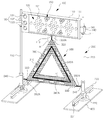
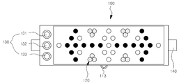
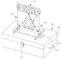
도 1은 본 발명의 바람직한 실시예에 따른 차량용 비상경고등의 전체 구성을 나타낸 사시도,
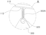
도 2는 도 1의 A에 대한 부분 확대도,
도 3은 본 발명의 바람직한 실시예에 따른 차량용 비상경고등의 전체 구성을 나타낸 분리 사시도,
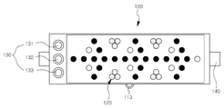
도 4a는 본 발명의 바람직한 실시예에 따른 제1표시부의 구성을 나타낸 평면도, 정면도 및 측면도,
도 4b는 본 발명의 바람직한 실시예에 따른 케이스에 체결부가 장착되는 구성을 나타낸 분리 사시도,
도 5는 본 발명의 바람직한 실시예에 따른 지지부의 구성을 나타낸 분리 사시도,
도 6a 내지 도 6c는 본 발명의 바람직한 실시예에 따른 스위치부의 온/오프 동작에 의해 광원부가 선택적으로 점등되는 상태를 나타낸 정면도,
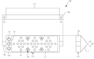
도 7은 본 발명의 바람직한 실시예에 따른 보관박스에 각 구성품이 분리 보관된 상태를 나타낸 사시도,
도 8은 본 발명의 바람직한 실시예에 따른 차량용 비상경고등이 보관박스의 상부에 장착된 상태를 나타낸 사시도,
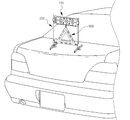
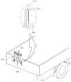
도 9a 및 도 9b는 본 발명의 바람직한 실시예에 따른 차량용 비상경고등이 차량의 트렁크 및 적재함의 배면에 장착된 상태를 나타낸 사시도,
도 10a 내지 도 10c는 본 발명의 바람직한 실시예에 따른 케이스가 체결부의 체결나사부를 중심으로 회동되는 동작상태를 나타낸 측면도이다.1 is a perspective view showing the overall configuration of a vehicle emergency warning light according to a preferred embodiment of the present invention,
2 is an enlarged view of a portion of A of FIG. 1;
3 is an exploded perspective view showing the overall configuration of a vehicle emergency warning light according to an embodiment of the present invention,
4A is a plan view, a front view, and a side view showing a configuration of a first display unit according to a preferred embodiment of the present invention;
Figure 4b is an exploded perspective view showing a configuration that the fastening portion is mounted to the case according to an embodiment of the present invention,
Figure 5 is an exploded perspective view showing the configuration of the support according to a preferred embodiment of the present invention,
6A to 6C are front views showing a state in which a light source unit is selectively turned on by an on / off operation of a switch unit according to a preferred embodiment of the present invention;
Figure 7 is a perspective view showing a state in which each component is stored separately in a storage box according to an embodiment of the present invention,
8 is a perspective view showing a state in which an emergency warning light for a vehicle is mounted on an upper portion of a storage box according to a preferred embodiment of the present invention;
9A and 9B are perspective views illustrating a state in which a vehicle emergency warning light is mounted on a trunk of a vehicle and a rear surface of a loading box according to a preferred embodiment of the present invention;
10A to 10C are side views illustrating an operating state in which a case is rotated about a fastening screw part of a fastening part according to an exemplary embodiment of the present invention.
상술한 본 발명의 목적, 특징들 및 장점은 다음의 상세한 설명을 통하여 보다 분명해질 것이다. 이하, 본 발명의 바람직한 실시예를 첨부한 도면에 의거하여 설명하면 다음과 같다.The objects, features and advantages of the present invention described above will become more apparent from the following detailed description. Hereinafter, preferred embodiments of the present invention will be described with reference to the accompanying drawings.
도 1은 본 발명의 바람직한 실시예에 따른 차량용 비상경고등의 전체 구성을 나타낸 사시도, 도 2는 도 1의 A에 대한 부분 확대도, 도 3은 본 발명의 바람직한 실시예에 따른 차량용 비상경고등의 전체 구성을 나타낸 분리 사시도, 도 4a는 본 발명의 바람직한 실시예에 따른 제1표시부의 구성을 나타낸 평면도, 정면도 및 측면도, 도 4b는 본 발명의 바람직한 실시예에 따른 케이스에 체결부가 장착되는 구성을 나타낸 분리 사시도, 도 5는 본 발명의 바람직한 실시예에 따른 지지부의 구성을 나타낸 분리 사시도, 도 6a 내지 도 6c는 본 발명의 바람직한 실시예에 따른 스위치부의 온/오프 동작에 의해 광원부가 선택적으로 점등되는 상태를 나타낸 정면도, 도 7은 본 발명의 바람직한 실시예에 따른 보관박스에 각 구성품이 분리 보관된 상태를 나타낸 사시도, 도 8은 본 발명의 바람직한 실시예에 따른 차량용 비상경고등이 보관박스의 상부에 장착된 상태를 나타낸 사시도, 도 9a 및 도 9b는 본 발명의 바람직한 실시예에 따른 차량용 비상경고등이 차량의 트렁크 및 적재함의 배면에 장착된 상태를 나타낸 사시도, 도 10a 내지 도 10c는 본 발명의 바람직한 실시예에 따른 케이스가 체결부의 체결나사부를 중심으로 회동되는 동작상태를 나타낸 측면도이다.1 is a perspective view showing the overall configuration of a vehicle emergency warning light according to a preferred embodiment of the present invention, Figure 2 is a partially enlarged view of the A of Figure 1, Figure 3 is an overall vehicle emergency warning light according to a preferred embodiment of the present invention 4A is a plan view, a front view, and a side view showing a configuration of a first display unit according to a preferred embodiment of the present invention, and FIG. 4B is a configuration in which a fastening portion is mounted to a case according to a preferred embodiment of the present invention. 5 is an exploded perspective view showing a configuration of a support according to a preferred embodiment of the present invention, Figures 6a to 6c is a light source selectively turned on by the on / off operation of the switch unit according to a preferred embodiment of the present invention 7 is a perspective view showing a state in which each component is separately stored in a storage box according to a preferred embodiment of the present invention. 8 is a perspective view showing a state in which a vehicle emergency warning light is mounted on an upper portion of a storage box according to a preferred embodiment of the present invention. FIGS. 9A and 9B are views illustrating a trunk and a storage box of a vehicle emergency warning light according to a preferred embodiment of the present invention. 10A to 10C are side views illustrating a state in which a case according to a preferred embodiment of the present invention is rotated about a fastening screw part of a fastening part.
도 1 내지 도 10c에 도시된 바와 같이, 본 발명의 바람직한 실시예에 따른 차량용 비상경고등은, 제1표시부(100), 지지부(200) 및 제2표시부(300)를 포함한다.As illustrated in FIGS. 1 to 10C, the vehicle emergency warning lamp according to the preferred embodiment of the present invention includes a
먼저, 상기 제1표시부(100)는, 후속하는 차량의 운전자에게 우회하는 방향 또는 현재의 비상상황에 대한 경고내용을 표시하는 표시판으로서, 일정크기의 내부공간이 형성된 케이스(110)와, 복수 개의 전구(121)가 기호(Sign) 또는 문자 형태로 배치되어 상기 케이스(110)의 앞면(111)에 장착되는 광원부(120)와, 온/오프 동작에 의해 상기 광원부(120)를 선택적으로 점멸시키는 스위치부(130) 및, 상기 케이스(110)의 양 측단에 장착되며 수직방향으로 통공된 지지대삽입공(141)이 형성된 체결부(140)를 포함하여 구비된다.First, the
여기서, 상기 케이스(110)는, 제1표시부(100)의 외관을 형성하여 각 구성품을 외부로부터 보호하는 구성요소로서, 제품의 경량화를 위해 경질의 합성수지 재질로 형성되며 우천시와 같은 악천후에도 사용할 수 있도록 케이스(110)의 내부는 밀봉되도록 구비되는 것이 바람직하다. 또한, 상기 케이스(110)의 앞면(111)은 후속하는 차량의 진행방향과 대향하도록 설치되며, 배면부(112)는 도 4a에 도시된 바와 같이 일정각도(θ)로 각이 진 형태로 돌출되어 형성될 수 있다. 이로 인하여 본 발명에 따른 차량용 비상경고등이 도로상에 설치되어 운용될 경우, 상기 제1표시부(100)의 후방으로 불어오는 강풍 또는 차량의 주행에 따른 공기압력을 상하로 분산시킬 수 있으므로 보다 견고하게 설치된 상태를 유지할 수 있다.Here, the
또한, 상기 전구(121)는 휘도 및 절전성을 고려하여 LED를 광원으로 이용하는 것이 바람직하고, 상기 전구(121)가 배치되는 특정 기호 또는 문자 형태는, 일반적으로 도로상에서 차량이 사고 또는 고장에 의해 정지하게 되는 경우에 후속하는 차량에게 이러한 상황을 안내하거나 경고하기 위한 내용의 기호 또는 문자의 형태로서, 상기 기호는 도 6a 내지 도 6c에 도시된 바와 같이 일방향 또는 양방향을 나타내는 ←, →, ↔ 등의 화살표를 포함하여 정지차량을 우회하기 위한 방향을 지시하기 위한 여러가지 형태의 방향지시 기호 및, 주의 상황을 나타내는 ※, ! 등의 주의기호가 포함될 수 있으며, 상기 문자는 정지 및 사고차량의 발생 및 우회 방향을 안내하는 문자로서 '우회', '사고발생', '위험', '비상' 및 '서행' 등의 내용으로 표시될 수 있다.In addition, it is preferable that the
즉, 상기 광원부(110)는, 현재 상황을 안내 및 경고하기 위해 상술한 바와 같은 다양한 형태의 특정 기호 또는 문자의 형태로 배치된 복수 개의 LED 전구(121)들의 조합체를 의미한다.That is, the
상기 스위치부(130)는, 상기 광원부(120)를 선택적으로 점멸시키기 위해 조작되는 사용자 입력수단으로서, 광원부(120)의 구동을 작동(On) 또는 차단(Off)시키기 위한 온/오프 스위치(131)와, 상기 광원부(120)가 구동된 상태에서 상기 광원부(120)에서 표시되는 화살표의 방향 또는 안내되는 문자의 종류를 선택하기 위한 출력선택 스위치(132)를 포함하여 구비되며, 케이스(110)의 내부에 장착된 구동회로 및 배터리에 의해 사용자 입력에 대응하여 광원부(120)를 선택적으로 점멸시키며, 토클스위치, 락커스위치, 푸쉬버튼스위치 등의 형태로 형성될 수 있다. 따라서, 상기 스위치부(130)는, 후속차량의 운전자에게 효과적으로 화살표의 지시방향을 안내하기 위해 상기 전구(121)가 일방향을 지시하는 화살표 형태로 배치되는 것이 바람직하다. 이때, 상기 정지차량이 도로의 중앙차선에서 정지되었을 경우, 상기 정지차량을 우회하는 방향은 중앙차선의 양쪽차선 방향으로 지시되어야 하는 경우가 발생할 수 있다. 이러한 경우, 상기 스위치부(130)를 조작하여 도 6a 내지 도 6c와 같이 단 방향 또는 양 방향으로 화살표의 방향이 향하도록 제어할 수 있다.The
여기서, 상기 광원부(120)는, 사용자의 조작에 따라 점등되어 주변을 조명하는 조명부(150)를 더 포함하며, 상기 스위치부(130)는, 상기 조명부(150)를 선택적으로 점멸시키기 위해 조작되는 조명스위치(133)를 더 포함할 수 있다.Here, the
상기 조명부(150)는 도 1에 도시된 바와 같이 케이스(110)의 앞면(111)에 장착된 조명수단으로서 백색 또는 황색 등의 고휘도 LED를 광원으로 이용함과 동시에 빛을 분산시키기 위한 확산판이 함께 구비되는 것이 바람직하며, 도면에는 세 개의 전구가 하나의 그룹을 이루어 상부와 하부에 각 2개 그룹으로 위치하여 구비된 것으로 도시되었으나, 이에 국한되는 것은 아니며 조명하고자 하는 조명구역의 범위 및 사용의 편의성을 고려하여 복수 개의 전구가 케이스(110)의 앞면(111), 측면, 상면, 하면 및 배면부(112)에 위치하여 장착될 수 있음은 물론이다.As shown in FIG. 1, the
상기 체결부(140)는, 상기 지지부(200)를 제1표시부(100)의 양 측에 체결시킬 수 있도록 상기 제1표시부(100)의 양 측단에 장착되는 구성요소로서, 내부에는 상기 지지부(200)의 지지대(210)의 상단부가 관통삽입되도록 수직방향으로 통공된 지지대삽입공(141)이 형성된다. 즉, 상기 체결부(140)에 형성된 지지대삽입공(141)에 지지대(210)가 각각 삽입됨으로써 상기 제1표시부(100)의 하중이 상기 지지부(200)에 지지되는 상태로 상기 제1표시부(100)와 지지부(200)가 상호 체결되는 것이다.The
여기서, 상기 체결부(140)는, 도 4a 및 도 4b에 도시된 바와 같이, 상기 체결부(140)의 일측면에는 상기 케이스(110)의 양 측단에 형성된 체결공(114)에 삽입되어 체결너트(144)와 회전결합하는 체결나사부(142)가 형성되어, 상기 체결나사부(142)와 체결너트(144)의 상호 결합에 의해 상기 체결부(140)가 상기 케이스(110)의 양 측단에 장착되며, 상기 체결부(140)의 일측면에는 상기 체결나사부(142)와 인접한 위치에 상기 케이스(110)의 양 측단에 형성된 호(Arc) 형상의 안내홈(114)에 삽입되는 돌기부(143)가 형성되어, 상기 안내홈(114)의 내부에서 상기 돌기부(143)가 슬라이딩 이동하며 상기 체결나사부(142)를 중심으로 상기 케이스(110)가 회동되도록 구비된다.Here, the
즉, 상기 체결나사부(142)는, 상기 케이스(110)의 측단벽(116)을 사이에 두고 상기 케이스(110)의 내측에서 회전삽입되는 체결너트(144)와 체결되어 상기 체결부(140)를 케이스(110)의 양 측단에 장착시키기 위한 수단으로서의 기능을 수행하며, 상기 돌기부(143)와 안내홈(115)은, 상기 케이스(110)가 체결나사부(142)를 중심으로 상기 광원부(120)의 표시방향이 상방 또는 하방을 지향하도록 회동하되, 일정 각도 이상으로 회동되지 않도록 안내홈(115)의 양단에 상기 돌기부(143)가 걸리게 되어 케이스(110)의 회동 범위를 제한하기 위한 수단이다.That is, the
또한, 상기 체결너트(144)는, 상기 케이스(110)의 측단벽(116)을 사이에 두고 상기 체결너트(144)에 회전삽입하되, 상기 체결너트(144)와 측단벽(116) 사이에는 상기 케이스(110)가 상기 체결나사부(142)를 중심으로 회동하더라도 상기 체결나사부(142)와 체결너트(144)의 회전결합이 풀어지지 않도록 상기 체결나사부(142)에 관통삽입되는 와셔(142)가 구비되는 것이 바람직하다.In addition, the fastening nut 144 is rotationally inserted into the fastening nut 144 with the side end wall 116 of the
따라서, 도 10a에 도시된 바와 같이, 상기 체결부(140)의 지지대삽입공(141)에 지지부(200)가 삽입된 상태에서 케이스(110)가 회전하지 않게 되면, 상기 제1표시부(100)의 표시방향은 직전방을 항게게 된다. 또한, 도 10b 및 도 10c에 도시된 바와 같이, 상기 체결나사부(142)를 중심으로 상기 케이스(110)가 시계방향 또는 반시계방향으로 회전하게 되면 회전한 각도에 대응하는 일정 각도로 상기 제1표시부(100)의 표시방향은 상부 또는 하부를 지향하여 안내 및 경고 내용을 표시할 수 있다. Therefore, as shown in FIG. 10A, when the
상기 지지부(200)는, 상기 제1표시부(100)와 체결되어 제1표시부(100)의 하중을 지지하는 구성요소로서, 상기 지지대삽입공(141)에 상단부가 삽입되며, 하단부에는 차량의 외부면 또는 지지판(400)에 부착되는 자석(222)이 구비되어, 상기 제1표시부(100)가 일정높이에 위치하도록 제1표시부(100)와 체결된다.The
여기서, 상기 지지부(200)는, 상단부가 상기 지지대삽입공(141)에 삽입되며 하단부는 고정부(220)의 삽입공A(221)에 삽입되는 막대형상의 지지대(210)와, 상기 지지대(210)의 하단부가 삽입되는 삽입공A(221)가 형성되며 상기 자석(222)이 내장되는 고정부(220) 및, 상기 고정부(220)에서 일방향으로 연장된 형태로 결합되며, 상기 차량의 외부면 또는 지지판(400)을 지지하여 상기 지지부(200)의 유동을 고정시키는 하나 이상의 보조지지대(230)를 포함한다. 또한, 보조지지대(230)의 일측에는 삽입공A(221)가 형성된 방향과 직교되는 방향으로 연장된 형태로 상기 고정부(220)에 결합되는 것이 바람직한데, 이로 인해 상기 제1표시부(100)에 가해지는 강풍 또는 후속차량에 의한 공기압력에 의해 차량용 비상경고등이 유동되는 현상을 방지할 수 있다. 즉, 도 1과 같이, 상기 보조지지대(230)가 상기 제1표시부(100) 및 제2표시부(300)와 직교된 상태로 장착되므로 차량용 비상경고등이 전방 또는 후방으로 전복되는 것을 방지할 수 있는 것이다.Here, the
또한, 상기 제1표시부(100)는 체결부(140)에 지지부(200)의 지지대(210)가 삽입되어 체결되되, 상기 지지대(210)가 삽입된 상태에서 일정 높이에 위치하도록 상기 지지대(210)에 관통 삽입되어 상기 지지대(210)의 외주연을 둘러싸는 형태로 구비되는 멈춤패킹(211)에 상기 체결부(140)의 하단부가 지지된다.In addition, the
즉, 본 발명에 따른 차량용 비상경고등은, 후속차량의 운전자가 원거리에서도 용이하게 식별할 수 있도록 제1표시부(100)의 설치높이를 조절할 수 있는데, 이를 위해 상기 지지부(200)는 상기 지지대(210)의 일측에 상기 체결부(140)를 지지하는 멈춤패킹(211)이 삽입되어 구비되는 것이다.That is, the emergency warning light for a vehicle according to the present invention may adjust the installation height of the
상기 멈춤패킹(211)은, 지지대(210)의 일 위치에서 상기 체결부(140)의 하단부를 지지한 상태로 고정될 수 있도록 고무재질로 형성되며, 상기 지지대(210)가 삽입되는 내부 통공의 직경은 상기 지지대(210)의 외경보다 작은 크기로 형성되는 것이 바람직하다.The stop packing 211 is formed of a rubber material so that it can be fixed in a state supporting the lower end of the
따라서, 상기 멈춤패킹(211)은 상기 지지대(210)의 외부면과 상기 통공의 내부면이 접촉됨에 따라 발생하는 마찰력에 의해 상기 체결부(140)의 하중을 지지한 상태로 고정될 수 있으며, 고무재질로 형성되기 때문에 사용자가 상기 멈춤패킹(211)에 상기 일정크기의 힘으로 상기 지지대(210)의 길이방향으로 작용력을 가하는 경우 상기 멈춤패킹(211)의 내경이 늘어나면서 고정된 일 위치를 조절할 수 있는 것이다.Therefore, the stop packing 211 may be fixed while supporting the load of the
여기서, 상기 멈춤패킹(211)은 도 3에 도시된 바와 같이 상기 지지대(210)의 외부면과의 마찰력을 증대시키기 위해 복수 개로 구비될 수 있는데, 이 경우 상기 제1표시부(100)의 설치위치를 조절하기 위해서는 최상부 또는 최하부에 위치한 멈춤패킹(211)부터 위치를 이동시킨 후 인접한 멈춤패킹(211) 순으로 위치를 이동시켜 변경하고자 하는 위치로 조절할 수 있다. 즉, 상기 복수 개의 멈춤패킹(211)은 개별 단위로 위치 이동하여 전체의 멈춤패킹(211)을 이동시킬 수 있다.Here, the stop packing 211 may be provided in plurality in order to increase the friction with the outer surface of the
한편, 상기 지지대(210)가 지지대삽입공(141)에 삽입되는 경우, 상기 지지부(200)의 단면이 원형일 경우에는 상기 지지대삽입공(141) 내에서 상기 지지대(210)가 회전하게 되어 각 구성품간의 결합상태에 유동이 발생할 수 있다.On the other hand, when the
따라서, 본 발명에 따른 차량용 비상경고등에서는, 도 5에 도시된 바와 같이, 지지대(210)의 외부면의 일측이 각이 진 형태로 형성할 수 있으며, 상기 지지대(210)의 단면의 형태와 대응하도록 지지대삽입공(141)의 내부 형태를 형성할 수 있다. 이로 인하여, 상기 지지대(210)가 지지대삽입공(141)의 내부에 삽입된 상태에서 회전하는 현상을 방지할 수 있는 것이다.
Therefore, in the vehicle emergency warning light according to the present invention, as shown in Figure 5, one side of the outer surface of the
상기 제2표시부(300)는, 상기 제1표시부(100)와 함께 후속하는 차량의 운전자에게 비상상황을 나타내기 위한 비상표지 부재로서, 상기 케이스(110)의 하단부 및 지지부(200)의 측부와 각각 체결되어 상기 제1표시부(100)의 하부에 장착되되, 앞면에는 빛을 반사시키는 반사판(310) 또는 빛을 발광하는 전구가 구비된다. 여기서, 상기 제2표시부(300)는 통상적인 안전 삼각대와 같은 삼각형의 형상으로 형성될 수 있는데, 이때, 상기 제2표시부(300)의 중앙 및 테두리에는 제2표시부(300)를 향해 불어오는 바람 또는 공기압력이 통과할 수 있도록 제1통공(340A) 및 제2통공(340B)이 형성될 수 있다. 이로 인해, 상기 바람 또는 공기압력에 대항하는 제2표시부(300)의 마찰력이 감소되어 차량용 비상경고등이 전방 또는 후방으로 넘어지는 현상을 방지할 수 있다.The
또한, 상기 제2표시부(300)의 반사판(310)에는 상기 반사판(310)의 형상이 원거리에서도 명확하게 보일 수 있도록 상기 반사판(310)의 갖는 색상과 대비되는 색상으로 상기 반사판(310)의 중앙을 따라 삼각형상으로 형성되는 대비라인부(360)가 배치될 수 있다.In addition, the
더불어, 상기 제2표시부(300)는, 삼각형의 판 형상으로 형성되되, 상기 케이스(110)의 하단부에 형성된 체결고리A(113)와 상기 제2표시부(300)의 상부 모서리를 상호 연결하는 탄성부재A(350A)에 의해 상기 제1표시부(100)와 체결되며, 상기 지지부(200)에 구비된 고정부(220)의 측부에 형성된 체결고리B(240)와 상기 제2표시부(300)의 양 측부 모서리를 상호 연결하는 탄성부재B(350B)에 의해 상기 지지부(200)와 체결된다. 여기서, 상기 탄성부재A(350A) 및 탄성부재B(350B)는 상기 제1표시부(100)와 제2표시부(300), 지지부(200)와 제2표시부(300)를 각각 연결하는 연결부재로서, 상기 제1표시부(100), 제2표시부(300) 및 지지부(200)가 각각 체결된 상태에서 상기 제2표시부(300)를 향해 불어오는 바람 또는 공기 압력에 의해 상기 제2표시부(300)가 전후로 반동하며 상기 바람 또는 공기 압력에 대항하는 마찰력이 감소되도록 일정 크기의 탄성력이 구비될 수 있으며, 보다 바람직하게는 양단에 연결고리가 형성된 용수철의 형태로 형성될 수 있다.In addition, the
즉, 상기 탄성부재A(350A)의 일단은 제1표시부(100)의 하단부의 체결고리A(113)에 삽입되어 체결되며 타단은 제2표시부(300)의 상부 모서리에 형성된 체결구A(320)에 삽입되어 체결됨으로써 상기 제2표시부(300)의 상부가 제2표시부(300)의 하부에 지지되어 장착되며, 상기 탄성부재B(350B)의 일단은 상기 고정부(220)의 체결고리B(240)에 삽입되어 체결되며 타단은 제2표시부(300)의 양 측단 모서리에 형성된 체결구B(330)에 삽입되어 체결됨으로써 상기 제2표시부(300)의 양 측부가 상기 지지부(200)에 지지되어 장착되는 것이다.That is, one end of the
한편, 상기 보관박스(500)는, 내부에 상기 제1표시부(100), 지지부(200) 및 제2표시부(300) 등이 보관되는 내부공간이 형성되며, 외부면에는 상기 지지부(200)의 자석이 부착되도록 자성(Magnetic)의 재질로 형성된 지지판(400)을 포함하여 구비될 수 있다.On the other hand, the
즉, 도 7 및 도 8에 도시된 바와 같이, 상기 내부공간에는 상기 제1표시부(100), 지지부(200) 및 제2표시부(300) 등의 각 구성품을 분리 또는 결합한 상태의 상기 각 구성품의 외형과 동일한 형상의 홈이 형성되어 상기 홈에 상기 각 구성품이 취부된다.That is, as shown in FIG. 7 and FIG. 8, each of the components of the
이때, 도 7에 도시된 바와 같이 상기 각 구성품은 각각 일부분이 노출된 형태로 상기 홈에 삽입됨으로써 사용자가 각 구성품을 용이하게 꺼내거나 삽입할 수 있도록 구비되는 것이 바람직하다. 또한, 상기 보관박스(500)의 일측에는 내부공간을 개방 또는 커버할 수 있도록 하는 덮개(530)가 구비되며, 상기 덮개(530)는 잠금장치(510)에 의해 선택적으로 잠금상태가 고정되도록 구비될 수 있다.In this case, as shown in FIG. 7, the respective components may be inserted into the grooves with portions partially exposed so that the user may easily remove or insert the respective components. In addition, one side of the
더불어, 본 발명에 따른 차량용 비상경고등은, 정지차량의 외부면 즉, 차량의 트렁크, 천정 및 적재함 등에 장착이 불가할 경우에, 도 8에 도시된 바와 같이 상기 보관박스(500)의 상부 외부면에 구비된 상기 지지판(400)에 상기 지지부(200)의 자석(222)이 부착됨으로써 상기 보관박스(500)에 의해 지지되어 고정 설치될 수 있다.In addition, the emergency warning light for a vehicle according to the present invention, when it is impossible to mount on the outer surface of the stationary vehicle, that is, the trunk, the ceiling and the storage box of the vehicle, as shown in Figure 8 the upper outer surface of the
여기서, 도 8에는 상기 지지판(400)이 사각의 납작한 바(Bar) 형상으로 형성되어, 복수 개의 지지부(200)가 동시에 장착되는 실시예를 도시하고 있으나, 이에 국한되지 않고 상기 지지판(400)은 원형 또는 다각형의 형상으로 형성되거나 두 개 이상으로 구비되어, 도 1과 같이 각각의 지지부(200)가 개별적으로 부착되어 장착될 수 있음은 물론이다. 또한, 상기 보관박스(500)의 외부에는 사용자가 용이하게 휴대 및 운반할 수 있도록 손잡이(520)가 장착될 수 있다.8 illustrates an embodiment in which the
또한, 상기 지지판(400)은 상기 보관박스(500)의 상부에 장착될 수 있으며, 상기 보관박스(500)의 내부에 차량용 비상경고등의 각 구성품과 함께 보관될 수도 있다.In addition, the
즉, 본 발명에 따른 차량용 비상경고등을 정지한 차량과 이격하여 전방에 설치될 경우, 도 1과 같이 상기 지지판(400)을 도로의 지면 위에 배치한 상태에서 상기 지지판(400)의 상부에 지지부(200)를 부착하여 차량용 비상경고등을 설치할 수도 있는 것이다.
That is, when the vehicle emergency warning light according to the present invention is installed in the front spaced apart from the stopped vehicle, as shown in Figure 1 the
다음으로는, 본 발명의 바람직한 실시예에 따른 차량용 비상경고등의 동작원리를 설명하기로 한다.Next, the operation principle of an emergency warning light for a vehicle according to a preferred embodiment of the present invention will be described.
본 발명의 차량용 비상경고등은, 평상시 보관 및 운반이 용이하도록 상기 보관박스(500)의 내부공간에 보관될 수 있다. 도로상에서 차량이 고장나거나 사고가 발생하여 후속차량의 운전자에게 비상 상황임을 알려야 할 상황이 발생할 경우, 운전자는 상기 보관박스(500)에 보관된 차량용 비상경고등의 각 구성품을 꺼내어 각 구성품을 상호 결합한다.Emergency warning light for a vehicle of the present invention may be stored in the inner space of the
먼저, 지지부(200)의 고정부(220)에 보조지지대(230) 및 지지대(210)를 각각 삽입하여 장착하며, 제1표시부(100)가 장착될 설치 높이를 고려하여 상기 지지대(210) 상의 일 위치에 멈춤패킹(211)을 배치시킨 후, 상기 지지대(210)의 상단부를 체결부(140)의 지지대삽입공(141)에 삽입하되 상기 멈춤패킹(211)과 상기 체결부(140)의 하단부가 접촉되도록 장착함으로써 상기 제1표시부(100)와 지지부(200)를 상호 체결시킨다. 이때, 제1표시부(100)의 표시방향을 고려하여 상기 케이스(110)의 양 측단에 장착된 체결부(140)의 체결나사부(142)를 중심으로 상기 케이스(110)를 시계방향 또는 반시계방향으로 회전시켜 표시방향을 결정한다.First, the
이후, 제1표시부(100)의 체결고리A(113)와 제2표시부(300)의 상부 모서리의 체결구A(320), 상기 고정부(220)의 체결고리B(240)와 제2표시부(300)의 측부 모서리의 체결구B(330)를 탄성부재A(350A) 및 탄성부재B(350B)를 이용하여 각각 연결함으로써, 상기 제1표시부(100)의 하부에 제2표시부(300)가 배치된 상태에서, 제2표시부(300)의 상부는 제1표시부(100)의 하단부에 지지되며 제2표시부(300)의 양 측부는 지지부(200)의 측부에 지지되도록 상기 제1표시부(100), 지지부(200) 및 제2표시부(300)가 상호 체결한다.Thereafter, the
상기와 같이, 제1표시부(100), 지지부(200) 및 제2표시부(300)의 결합이 완료되면, 스위치부(130)의 온/오프 스위치(131)를 조작하여 광원부(120)가 작동하도록 구동시키며, 출력선택 스위치(132)를 조작하여 현재의 비상상황에서 적절한 기호 또는 문자를 선택한 후, 정지차량의 차종 또는 상황에 따라 트렁크, 천정 및 적재함 등의 차량 외부면에 상기 지지부(200)에 내장된 자석(222)을 부착시켜 본 발명에 따른 차량용 비상경고등을 고정 설치할 수 있다. As described above, when coupling of the
이때, 도 9a에 도시된 바와 같이, 상기 차량용 비상경고등이 장착될 차량의 외부면이 트렁크 또는 천정 등과 같이 수평면인 경우에는, 상기 지지대(210)의 하단부가 고정부(220)의 삽입공A(221)에 삽입되어 체결되며, 도 9b와 같이 상기 차량이 트럭과 같이 트렁크 및 천정 등에 부착하기가 제한되는 경우에는 상기 지지대(210)의 하단부를 고정부(220)의 삽입공B(231)에 삽입하여 체결할 수 있다.In this case, as shown in Figure 9a, when the outer surface of the vehicle to be mounted the emergency warning light for the vehicle is a horizontal plane, such as a trunk or ceiling, the lower end of the
즉, 본 발명에 따른 차량용 비상경고등은, 승용차의 트렁크 또는 천정 등의 상부면에 지지부(200)가 수평상태로 부착할 수 있음은 물론, 트럭과 같이 수평상태로의 부착이 제한되는 경우에는 적재함의 측부면에 상기 지지부(200)가 수직상태로 부착할 수 있으므로 사용자의 차종에 관계없이 사용 가능한 효과를 구현할 수 있는 것이다.That is, the vehicle emergency warning light according to the present invention, the
한편, 본 발명의 차량용 비상경고등을 차량의 외부면에 장착하여 운용하기가 제한되는 경우에는, 상기 보관박스(500)의 외부에 장착된 지지판(400)에 상기 지지부(200)의 자석(222)을 부착하거나, 상기 지지판(400)을 도로상에 배치한 상태에서 상기 지지판(400)의 상부에 차량용 비상경고등을 장착함으로써 정지차량과 이격되어 설치운용할 수 있다. On the other hand, when mounting the vehicle emergency warning light of the present invention is limited to the operation of the outer surface of the vehicle, the
상술한 바와 같이 본 발명의 바람직한 실시예에 따른 차량용 비상경고등의 구성에 의해, 제1표시부(100)와 함께 안전 삼각대 형상의 제2표시부(300)를 장착 가능하여, 도로상에서 고장 또는 사고 인하여 차량이 정지할 경우 고장자동차 표지에 대한 규정을 준수할 수 있으므로 안전 삼각대를 별도로 설치하여야 하는 불편함을 방지할 수 있음은 물론, LED 전구(121)를 광원으로 이용하여 경고내용을 표시하며, 차량의 트렁크, 천정 및 적재함 배면 등 차량의 높은 위치에 부착하여 사용될 수 있으므로, 후속차량의 운전자가 원거리에서도 용이하게 식별할 수 있다.As described above, by the configuration of the vehicle emergency warning lamp according to the preferred embodiment of the present invention, the
또한, 경고내용이 표시되는 제1표시부(100)의 설치높이를 조절할 수 있음은 물론, 상기 제1표시부(100)의 경고내용이 표시되는 각도를 상방 또는 하방으로 조절 가능하므로 도로상황 또는 비상상황에 따라 다양한 방식으로 경고내용을 표시할 수 있으며, 지지부(200)에 내장된 자석(222)에 의해 설치된 상태가 견고하게 고정됨은 물론, 보조지지대(230), 제1통공(340A), 제2통공(340B), 탄성부재A(350A) 및 탄성부재B(350B) 등의 구성을 통해 고정력이 더욱 증가되거나 바람에 의한 저항력이 감소되므로 강풍 또는 후속차량에 의한 공기압력에 의해서도 넘어지지 않는 효과를 제공한다.In addition, it is possible to adjust the installation height of the
이상에서 설명한 본 발명은 전술한 실시예 및 첨부된 도면에 의해 한정되는 것이 아니고, 본 발명의 기술적 사상을 벗어나지 않는 범위 내에서 여러 가지 치환, 변형 및 변경이 가능함은 본 발명이 속하는 기술분야에서 통상의 지식을 가진 자에게 명백할 것이다.
The present invention described above is not limited to the above-described embodiment and the accompanying drawings, and various substitutions, modifications, and changes are possible within the scope without departing from the technical spirit of the present invention. It will be evident to those who have knowledge of.
100...제1표시부 110...케이스
120...광원부 130...스위치부
140...체결부 200...지지부
210...지지대 220...고정부
230...보조지지대 300...제2표시부
310...반사판 400...지지판
500...보관박스100 ...
120 ...
140.
210 ... support 220 ... government
230 ...
310 ...
500 ... Storage Box
Claims (4)
상기 지지대삽입공(141)에 상단부가 삽입되며, 하단부에는 차량의 외부면 또는 지지판(400)에 부착되는 자석(222)이 구비되어, 상기 제1표시부(100)가 일정높이에 위치하도록 지지하며 상기 제1표시부(100)와 체결되는 지지부(200);
삼각형의 판 형상으로 형성되되, 상기 케이스(110)의 하단부 및 상기 지지부(200)의 측부와 각각 체결되어 상기 제1표시부(100)의 하부에 수직방향으로 장착되며, 앞면에는 빛을 반사시키는 반사판(310) 또는 빛을 발광하는 전구가 구비된 제2표시부(300);를 포함하는 차량용 비상경고등.
A case 110 having a predetermined size of internal space, a plurality of light bulbs 121 disposed in the form of a sign or a letter, and mounted on the front surface 111 of the case 110, and on A switch unit 130 for selectively blinking the light source unit 120 by an on / off operation, and a fastening unit 140 formed on both side ends of the case 110 and having a support insertion hole 141 through the vertical direction. A first display unit 100 including);
An upper end is inserted into the support insertion hole 141, and a lower end is provided with a magnet 222 attached to an outer surface of the vehicle or the support plate 400 to support the first display unit 100 at a predetermined height. A support part 200 coupled to the first display part 100;
It is formed in a triangular plate shape, is fastened to the lower end of the case 110 and the side of the support portion 200, respectively, mounted in a vertical direction on the lower portion of the first display unit 100, the reflecting plate reflecting light on the front surface Emergency warning lamp for a vehicle comprising a; 310 or the second display unit 300 is provided with a light bulb for emitting light.
상기 제2표시부(300)는,
상기 케이스(110)의 하단부에 형성된 체결고리A(113)와 상기 제2표시부(300)의 상부 모서리를 상호 연결하는 탄성부재A(350A)에 의해 상기 제1표시부(100)와 체결되며,
상기 지지부(200)의 측부에 형성된 체결고리B(240)와 상기 제2표시부(300)의 측부 모서리를 상호 연결하는 탄성부재B(350B)에 의해 상기 지지부(200)와 체결되는 것을 특징으로 하는 차량용 비상경고등.
The method of claim 1,
The second display unit 300,
It is fastened with the first display unit 100 by an elastic member A (350A) that interconnects the upper edge of the second display unit 300 and the fastening ring A 113 formed at the lower end of the case 110,
The fastening ring B 240 formed at the side of the support part 200 and the support member 200 are fastened by an elastic member B 350B interconnecting the side edges of the second display part 300. Car emergency warning lights.
상기 지지부(200)는,
상단부가 상기 지지대삽입공(141)에 삽입되는 지지대(210)와,
상기 지지대(210)의 하단부가 삽입되는 삽입공a(221)가 형성되며 상기 자석(222)이 내장되는 고정부(220) 및,
상기 고정부(220)에서 일방향으로 연장된 형태로 결합되며, 상기 차량의 외부면 또는 지지판(400)을 지지하여 상기 지지부(200)의 유동을 고정시키는 하나 이상의 보조지지대(230)를 포함하며,
상기 보조지지대(230)의 일측에는 상기 삽입공a(221)가 형성된 방향과 직교되는 방향으로 상기 지지대(210)의 하단부가 삽입되는 삽입공B(231)가 형성된 것을 특징으로 하는 차량용 비상경고등.
The method of claim 1,
The support part 200,
A support 210 having an upper end inserted into the support insertion hole 141;
An insertion hole a 221 into which the lower end of the support 210 is inserted is formed, and a fixing part 220 in which the magnet 222 is embedded;
It is coupled in the form extending in one direction from the fixing portion 220, and includes one or more auxiliary support 230 for supporting the outer surface or the support plate 400 of the vehicle to fix the flow of the support 200,
Emergency warning light for a vehicle, characterized in that the insertion hole B (231) is formed at one side of the auxiliary support 230 is inserted into the lower end of the support 210 in a direction orthogonal to the direction in which the insertion hole a (221) is formed.
상기 제1표시부(100)는,
상기 체결부(140)의 일측면에는 상기 케이스(110)의 양 측단에 형성된 체결공(114)에 삽입되어 체결너트(144)와 회전결합하는 체결나사부(142)가 형성되고, 상기 체결나사부(142)와 체결너트(144)의 상호 결합에 의해 상기 체결부(140)가 상기 케이스(110)의 양 측단에 장착되며,
상기 체결부(140)의 일측면에는 상기 체결나사부(142)와 인접한 위치에 상기 케이스(110)의 양 측단에 형성된 호(Arc) 형상의 안내홈(114)에 삽입되는 돌기부(143)가 형성되어, 상기 안내홈(114)의 내부에서 상기 돌기부(143)가 슬라이딩 이동하며 상기 체결나사부(142)를 중심으로 상기 케이스(110)가 회동되는 것을 특징으로 하는 차량용 비상경고등. The method of claim 1,
The first display unit 100,
On one side of the fastening part 140, a fastening screw part 142 is inserted into the fastening holes 114 formed at both side ends of the case 110 to rotate with the fastening nut 144, and the fastening screw part ( 142 and the fastening nut 144 by mutual coupling the fastening portion 140 is mounted on both side ends of the case 110,
On one side surface of the fastening part 140 is formed a protrusion 143 is inserted into the arc-shaped guide groove 114 formed on both side ends of the case 110 at a position adjacent to the fastening screw unit 142. The emergency warning light for a vehicle, characterized in that the projection 143 is sliding in the guide groove 114 and the case 110 is rotated around the fastening screw 142.
Priority Applications (1)
| Application Number | Priority Date | Filing Date | Title |
|---|---|---|---|
| KR1020100093174A KR20120031663A (en) | 2010-09-27 | 2010-09-27 | Vehicle emergency warning light |
Applications Claiming Priority (1)
| Application Number | Priority Date | Filing Date | Title |
|---|---|---|---|
| KR1020100093174A KR20120031663A (en) | 2010-09-27 | 2010-09-27 | Vehicle emergency warning light |
Publications (1)
| Publication Number | Publication Date |
|---|---|
| KR20120031663A true KR20120031663A (en) | 2012-04-04 |
Family
ID=46135056
Family Applications (1)
| Application Number | Title | Priority Date | Filing Date |
|---|---|---|---|
| KR1020100093174A Abandoned KR20120031663A (en) | 2010-09-27 | 2010-09-27 | Vehicle emergency warning light |
Country Status (1)
| Country | Link |
|---|---|
| KR (1) | KR20120031663A (en) |
Cited By (5)
| Publication number | Priority date | Publication date | Assignee | Title |
|---|---|---|---|---|
| KR101388267B1 (en) * | 2014-02-10 | 2014-04-22 | 권재경 | Supporting apparatus of safety indicator for vehicle |
| CN103863179A (en) * | 2014-03-18 | 2014-06-18 | 四川金堂海纳生物医药技术研究所 | Safety ceiling lamp specially used for taxies |
| KR200481999Y1 (en) * | 2015-07-30 | 2016-12-06 | 김진권 | Roll type safety sign device for car that is easy to installation |
| CN108382298A (en) * | 2018-03-28 | 2018-08-10 | 南京亚欣照明有限公司 | A kind of alarming device that municipal traffic is observed with nighttime emergency parking |
| WO2019004577A1 (en) * | 2017-06-27 | 2019-01-03 | 김인수 | Vehicle folding emergency warning lamp |
-
2010
- 2010-09-27 KR KR1020100093174A patent/KR20120031663A/en not_active Abandoned
Cited By (5)
| Publication number | Priority date | Publication date | Assignee | Title |
|---|---|---|---|---|
| KR101388267B1 (en) * | 2014-02-10 | 2014-04-22 | 권재경 | Supporting apparatus of safety indicator for vehicle |
| CN103863179A (en) * | 2014-03-18 | 2014-06-18 | 四川金堂海纳生物医药技术研究所 | Safety ceiling lamp specially used for taxies |
| KR200481999Y1 (en) * | 2015-07-30 | 2016-12-06 | 김진권 | Roll type safety sign device for car that is easy to installation |
| WO2019004577A1 (en) * | 2017-06-27 | 2019-01-03 | 김인수 | Vehicle folding emergency warning lamp |
| CN108382298A (en) * | 2018-03-28 | 2018-08-10 | 南京亚欣照明有限公司 | A kind of alarming device that municipal traffic is observed with nighttime emergency parking |
Similar Documents
| Publication | Publication Date | Title |
|---|---|---|
| JP3187899U (en) | Safety device for automatic lighting enhancement and warning when the vehicle door is opened | |
| US20050072350A1 (en) | Emergency signaling device | |
| KR101932959B1 (en) | Vehicle Emergency notification device for prevention of secondary accident and its method | |
| KR101314937B1 (en) | Triangle Band equipped in a Vehicle with Surface Radiation LED | |
| KR20120031663A (en) | Vehicle emergency warning light | |
| US20140300463A1 (en) | Multiple Color Hazard Warning/Signaling Device for Trailing End of Trunk Lid | |
| US9096978B2 (en) | Expandable roadside safety apparatus | |
| KR101219104B1 (en) | Street light apparatus for pedestrian crossing | |
| KR101506400B1 (en) | Car emergency display device using folding fan | |
| KR20120036112A (en) | Emergency lamp for car | |
| KR101097001B1 (en) | Crosswalk street lights to prevent vehicle accidents | |
| KR101775496B1 (en) | Roll type flexible LED emergency indicator light for vehicle | |
| CN107206935B (en) | Safe tripod | |
| US6466128B1 (en) | Vehicle door step equipped with warning indicator devices | |
| US20140352601A1 (en) | Disabled vehicle safety apparatus | |
| KR101982496B1 (en) | Apparatus For Emergency Lamp Shaped Like Umbrella | |
| KR101337335B1 (en) | Bollard | |
| KR101823654B1 (en) | Foldable emergency indicator light for vehicle | |
| KR20230112875A (en) | One-touch safety tripod for car | |
| KR20150031947A (en) | Vehicle-mounted type warning triangle device | |
| KR20170085669A (en) | Notification device risk for a vehicle having various mounting structures and display functions | |
| KR102048306B1 (en) | Safety sign board for car | |
| KR20120006152A (en) | Vehicle emergency warning light | |
| KR101731435B1 (en) | Arrow signs for car | |
| KR200390328Y1 (en) | A safe signal board for vehicles with high brightness light emitting diodes |
Legal Events
| Date | Code | Title | Description |
|---|---|---|---|
| A201 | Request for examination | ||
| PA0109 | Patent application |
Patent event code: PA01091R01D Comment text: Patent Application Patent event date: 20100927 |
|
| PA0201 | Request for examination | ||
| PG1501 | Laying open of application | ||
| E902 | Notification of reason for refusal | ||
| PE0902 | Notice of grounds for rejection |
Comment text: Notification of reason for refusal Patent event date: 20120509 Patent event code: PE09021S01D |
|
| E701 | Decision to grant or registration of patent right | ||
| PE0701 | Decision of registration |
Patent event code: PE07011S01D Comment text: Decision to Grant Registration Patent event date: 20120928 |
|
| NORF | Unpaid initial registration fee | ||
| PC1904 | Unpaid initial registration fee |