KR20120009132A - Mount bush of stabilizer bar for vehicle - Google Patents
Mount bush of stabilizer bar for vehicle Download PDFInfo
- Publication number
- KR20120009132A KR20120009132A KR1020100070996A KR20100070996A KR20120009132A KR 20120009132 A KR20120009132 A KR 20120009132A KR 1020100070996 A KR1020100070996 A KR 1020100070996A KR 20100070996 A KR20100070996 A KR 20100070996A KR 20120009132 A KR20120009132 A KR 20120009132A
- Authority
- KR
- South Korea
- Prior art keywords
- bush
- stabilizer bar
- insert
- sliding bearing
- rubber
- Prior art date
Links
Images


Classifications
-
- B—PERFORMING OPERATIONS; TRANSPORTING
- B60—VEHICLES IN GENERAL
- B60G—VEHICLE SUSPENSION ARRANGEMENTS
- B60G21/00—Interconnection systems for two or more resiliently-suspended wheels, e.g. for stabilising a vehicle body with respect to acceleration, deceleration or centrifugal forces
- B60G21/02—Interconnection systems for two or more resiliently-suspended wheels, e.g. for stabilising a vehicle body with respect to acceleration, deceleration or centrifugal forces permanently interconnected
- B60G21/04—Interconnection systems for two or more resiliently-suspended wheels, e.g. for stabilising a vehicle body with respect to acceleration, deceleration or centrifugal forces permanently interconnected mechanically
- B60G21/05—Interconnection systems for two or more resiliently-suspended wheels, e.g. for stabilising a vehicle body with respect to acceleration, deceleration or centrifugal forces permanently interconnected mechanically between wheels on the same axle but on different sides of the vehicle, i.e. the left and right wheel suspensions being interconnected
- B60G21/055—Stabiliser bars
-
- B—PERFORMING OPERATIONS; TRANSPORTING
- B60—VEHICLES IN GENERAL
- B60G—VEHICLE SUSPENSION ARRANGEMENTS
- B60G21/00—Interconnection systems for two or more resiliently-suspended wheels, e.g. for stabilising a vehicle body with respect to acceleration, deceleration or centrifugal forces
- B60G21/02—Interconnection systems for two or more resiliently-suspended wheels, e.g. for stabilising a vehicle body with respect to acceleration, deceleration or centrifugal forces permanently interconnected
- B60G21/04—Interconnection systems for two or more resiliently-suspended wheels, e.g. for stabilising a vehicle body with respect to acceleration, deceleration or centrifugal forces permanently interconnected mechanically
- B60G21/05—Interconnection systems for two or more resiliently-suspended wheels, e.g. for stabilising a vehicle body with respect to acceleration, deceleration or centrifugal forces permanently interconnected mechanically between wheels on the same axle but on different sides of the vehicle, i.e. the left and right wheel suspensions being interconnected
-
- B—PERFORMING OPERATIONS; TRANSPORTING
- B62—LAND VEHICLES FOR TRAVELLING OTHERWISE THAN ON RAILS
- B62D—MOTOR VEHICLES; TRAILERS
- B62D21/00—Understructures, i.e. chassis frame on which a vehicle body may be mounted
-
- B—PERFORMING OPERATIONS; TRANSPORTING
- B62—LAND VEHICLES FOR TRAVELLING OTHERWISE THAN ON RAILS
- B62D—MOTOR VEHICLES; TRAILERS
- B62D21/00—Understructures, i.e. chassis frame on which a vehicle body may be mounted
- B62D21/02—Understructures, i.e. chassis frame on which a vehicle body may be mounted comprising longitudinally or transversely arranged frame members
Abstract
Description
본 발명은 자동차의 현가장치에 적용되는 스테빌라이저 바의 마운트 부시에 관한 것으로서, 보다 상세하게는 미끄럼 베어링 구조를 이용하여 고질적 문제인 소음과 마찰을 저감시켜 자동차의 상품성 및 연비를 증대시키고, 내부로 이물질이 침투하여 미끄럼 베어링의 성능을 저하시키는 것을 방지할 수 있도록 한 자동차용 스테빌리이저 바의 마운트 부시에 관한 것이다.The present invention relates to a mount bush of a stabilizer bar applied to a suspension device of a vehicle, and more particularly, by using a sliding bearing structure to reduce noise and friction, which is a chronic problem, to increase the merchandise and fuel economy of a vehicle, and to provide foreign substances therein. The present invention relates to a mount bush of an automobile stabilizer bar capable of preventing penetration and deterioration of a sliding bearing.
자동차의 독립식 현가장치에 적용되는 스테빌라이저 바는 선회 또는 거친 노면의 주행시 차체의 롤 모션을 억제하여 차체의 평형을 유지시키는 일종의 비틀림 스프링이다.The stabilizer bar, which is applied to an independent suspension of a vehicle, is a torsion spring that maintains the balance of the vehicle body by suppressing the roll motion of the vehicle body when turning or driving on rough roads.
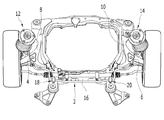
이러한 스테빌라이저 바의 일반적인 구성을 살펴보면, 도 1에서와 같이, 스테빌라이저 바(2)는 그 양단에 각각 컨트롤 링크(4)(6)를 개재시켜 로워 컨트롤 아암(8)(10) 또는 스트러트 어셈블리(12)(14)에 연결되고, 그 내측의 직선부 양측 부분이 서브 프레임(16)에 마운팅 부시(18)(20)를 개재시켜 고정된다.Looking at the general configuration of such a stabilizer bar, as shown in Figure 1, stabilizer bar (2) has a lower control arm (8) (10) or strut assembly, respectively, through control links (4) (6) at both ends thereof. (12) and (14), and both sides of the straight portion inside thereof are fixed to the subframe (16) via mounting bushes (18) and (20).
상기와 같은 스테빌라이저 바(2)는 차체의 롤링시 발생하는 좌우 휠을 지지하는 보조 스프링 기능을 하면서 좌우 휠이 동위상으로 움직일 때에는 힘을 받지 않고, 역위상으로 움직이는 경우에는 비틀림 탄성력에 의해 좌우 휠의 움직임을 구속하여 차체의 롤 거동을 억제하는 역할을 수행하게 된다.The
예컨대, 선회시 선회 외측 휠이 바운드를 하고, 선회 내측 휠이 리바운드를 할 때, 이들 양 휠의 움직임을 같게 하는 작용을 하여 차체의 기울기를 억제하게 되며, 반대로 좌우 휠이 동시에 같은 방향으로 동작될 때에는 작용하지 않게 되는 것이다.For example, when the turning outer wheel is bound and the turning inner wheel rebounds when turning, the movement of both wheels is made equal to suppress the inclination of the vehicle body. It will not work.
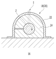
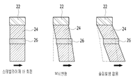
그리고 상기 스테빌라이저 바(2)의 직선부 양측을 서브 프레임(16)에 고정시켜 주는 마운팅 부시(18)(20)는 통상적으로 도 2의 A에 도시된 윤활 부시 타입의 마운트 부시와, 도 2의 B에 도시된 중철 부시 타입의 마운트 부시가 채용되고 있다.In addition, mounting
상기 윤활 부시 타입의 마운트 부시는 도 2의 A에서와 같이, 브라켓(22)과 윤활 성분이 첨가된 고무부시(24)로 구성되어 상기 브라켓(22)이 상기 고무부시(24)를 감싸는 형태로 차체 또는 서브 프레임(16)에 고정된다. The lubrication bush type mount bush is composed of a
또한 상기 고무부시(24)의 중앙부에는 원형 단면을 갖는 스테빌라이저 바(2)가 관통하는 형태로 고정되어 스테빌라이저 바(2)의 거동으로 인한 소음이나 진동을 차단하게 되며, 상기 고무부시(24)는 스테빌라이저 바(2)에 대한 압축력의 크기에 따라 롤 강성 크기에도 큰 영향을 미치게 된다.In addition, the stabilizer bar (2) having a circular cross section is fixed to the center portion of the rubber bush (24) to block the noise or vibration caused by the behavior of the stabilizer bar (2), the rubber bush (24) ) Has a great influence on the roll stiffness depending on the size of the compressive force on the
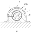
그리고 상기 중철 부시 타입의 마운트 부시는 도 2의 B에서와 같이, 상기 윤활 부시 타입의 마운트 부시와 마찬가지로 브라켓(22)과 고무부시(24)로 이루어지되, 상기 고무부시(24)의 내부에 중철 부시(26)를 삽입하여 스테빌리아저 바(2)의 회전시 슬립이 발생되지 않도록 하는 구조로 이루어진다.And the saddle stitch bush type mount bush is made of a
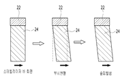
그러나 상기 윤활 부시 타입의 마운트 부시는 도 3의 A에서와 같이 스테빌라이저 바의 회전시 초기 대략 2 ~ 3°구간에서 고무부시의 변형이 발생한 후 슬립이 발생된다.However, in the lubrication bush type mount bush, as shown in FIG. 3A, slip occurs after the deformation of the rubber bush occurs in the initial approximately 2 to 3 ° section during rotation of the stabilizer bar.
상기와 같이 슬립이 발생된다고 하는 것은 소음 발생을 의미하며, 고무 노화가 진행될수록 소음이 커진다는 문제점을 내포하고 있다.As described above, the occurrence of slip means noise generation, and includes a problem that the noise increases as the rubber ages.
그리고 중철 부시 타입의 마운트 부시는 도 3의 B에서와 같이 슬립 발생이 없는 구조로서 소음 문제는 해결할 수 있으나, 회전방향 토크가 비례하여 증대되므로 차량의 거동이 과도한 경우 마찰이 증대되어 연비에 불리하다는 문제점을 내포하고 있다.In addition, the saddle-stitch bush-type mount bush has a structure without slip as shown in B of FIG. 3, but the noise problem can be solved. There is a problem.
따라서 본 발명은 상기와 같은 문제점을 해결하기 위하여 발명된 것으로서, 본 발명의 목적은 미끄럼 베어링 구조를 이용하여 고질적 문제인 소음과 마찰을 저감시켜 자동차의 상품성 및 연비를 증대시키고, 내부로 이물질이 침투하여 미끄럼 베어링의 성능을 저하시키는 것을 방지할 수 있도록 한 자동차용 스테빌리이저 바의 마운트 부시에 관한 것이다.Therefore, the present invention has been invented to solve the above problems, the object of the present invention by using a sliding bearing structure to reduce the noise and friction, which is a chronic problem, to increase the merchandise and fuel economy of the car, foreign matter penetrates into the interior The present invention relates to a mounting bush of an automobile stabilizer bar that can prevent the performance of a sliding bearing from being deteriorated.
상기 목적을 실현하기 위하여 본 발명은 청구범위 제1항에서와 같이, 스테빌라이저 바(102)의 직선부 양측을 서브 프레임(차체;104) 고정시켜 주는 마운트 부시(100)를 형성함에 있어서, In order to realize the above object, in the present invention, as in
스테빌라이저 바(102)의 고정부위에 직접 사출 형성되는 인서트(110)와; 좌,우 한쌍의 베어링(121)(122)으로 이루어져 상기 인서트(110)의 외주면에 윤활층을 가지고 결합되는 미끄럼 베어링(120)과; 상,하 고무부재(131)(132)로 이루어져 상기 미끄럼 베어링(120)의 외주측을 감싸는 형태로 결합되며, 양단부에 2차 시일링이 이루어지는 시일링 구조를 갖는 고무부시(130)와; 상기 고무부시(130)를 감싸면서 서브 프레임(차체)에 고정되는 브라켓(140)을 포함하여 이루어지는 자동차용 스테빌라이저 바의 마운트 부시를 제공한다.An
상기에서 인서트(110)는 청구범위 제2항에서와 같이, 스테빌라이저 바(102)의 외주면에 일정 길이를 갖고 직접 사출 성형되며, 양단부에 대직경의 플랜지(111)(112)가 형성되고, 중앙에 소정의 둘레턱(113)이 형성되며, 상기 둘레턱(113)과 양 플랜지(111)(112)사이에는 윤활제가 충진될 수 있는 둘레홈(114)이 형성됨을 특징으로 한다.In the
상기에서 미끄럼 베어링(120)은 청구범위 제3항에서와 같이, 좌,우 한쌍의 베어링(121)(122)으로 이루어지며, 상기 인서트(110)의 둘레턱(113)을 기준으로 양측에 배치되고, 양단부에는 고무부시(130)를 고정시켜 줄 수 있도록 상기 인서트(110)의 플랜지(111)(112) 보다 작은 플랜지(123)(124)가 형성됨을 특징으로 한다.In the sliding bearing 120 is made of a pair of left and
상기에서 미끄럼 베어링(120)을 형성하는 좌,우 베어링(121)(122)은 청구범위 제4항에서와 같이, 축방향으로 형성되는 일정 형태의 절개부(125)(126)에 의하여 오픈형으로 이루어짐을 특징으로 한다.The left and
상기에서 미끄럼 베어링(120)의 외주측에 배치되는 고무부시(130)는 청구범위 제5항에서와 같이, 상,하 고무부재(131)(132)로 이루어지며, 미끄럼 베어링(120)과 접촉되는 내경부의 안쪽에 내철(133)(134)이 매몰 형성됨을 특징으로 한다.The
상기에서 고무부시(130)를 형성하는 상,하 고무부재(131)(132)의 양단부에는 청구범위 제6항에서와 같이, 이물질 투입 및 그리스 누유 방지를 위한 립(Lip;135, 136)이 형성됨을 특징으로 한다.In both ends of the upper and
상기에서 립(135)(136)은 청구범위 제7항에서와 같이, 뿌리부가 단부 보다 두껍게 형성되고, 상기 립(135)(136)의 단부까지 상기 내철(133)(134)을 연장하여 매몰되도록 함을 특징으로 한다.In the lip (135) 136, the root portion is formed thicker than the end, as in claim 7, wherein the inner convex (133) 134 extending to the end of the rip (135) 136 It is characterized by.
상기에서 립(135)(136)의 내경부에는 청구범위 제8항에서와 같이, 인서트(110)의 양 플랜지(111)(112) 외측 모서리 부분을 압착할 수 있는 제1 시일링 턱(137)(138)을 형성하고, 양 플랜지(111)(112)의 외주면에 형성된 시일링 홈(115)(116)에 안착될 수 있는 제2 시일링 턱(139)(140)을 형성함을 특징으로 한다.In the inner diameter portion of the lip (135) 136 as described in
상기와 같이 구성되는 본 발명에 의하면, 인서트(110)가 스테빌라이저 바(102)에 직접 사출하는 방식으로 제작되는 바, 스테빌라이저 바(102)의 이탈 방지용 클램프 역할을 수행하고, 중앙 둘레턱(113)에 의하여 미끄럼 베어링(120)의 이탈을 방지할 수 있게 된다.According to the present invention configured as described above, the
그리고 인서트(110)와 미끄럼 베어링(120) 사이에 윤활제인 그리스가 충전되는 바, 전 거동 구간 마찰을 최소화할 수 있게 되며, 기동 토크 구간의 최소화로 소음 발생을 방지할 수 있게 된다.And the grease which is a lubricant is filled between the
또한, 미끄럼 베어링(120)이 한쌍의 좌,우 베어링(121)(122)으로 이루어짐과 동시에 오픈형으로 이루어짐으로써, 공차 관리 및 조립성이 향상된다.In addition, since the sliding bearing 120 is made of a pair of left and
그리고 고무부시(130)의 내경부에 내철(133)(134)이 적용됨으로써, 미끄럼 베어링(120)을 변형없는 형태로 고정시켜주게 되며, 특히 상기 립(135)(136)에 의하여 재1, 2 시일링 턱(137)(138),(139)(140)에 의하여 이물질 침투 및 그리스 누유를 방지할 수 있는 바, 미끄럼 베어링(120)의 성능 저하를 방지할 수 있게 된다.And by applying the
또한, 내철(133)(134)이 립(135)(136) 부분까지 연장되어 립(135)(136)을 지지하여 주게 되는 바, 차량의 롤 거동시 립(135)(136)의 변형을 최소화할 수 있게 되는 시일링 효과를 높일 수 있게 되는 것이다.In addition, the
이 도면들은 본 발명의 예시적인 실시예를 설명하는데 참조하기 위한 것으로서, 본 발명의 기술적 사상을 첨부한 도면에 한정해서 해석하여서는 안된다.
도 1은 본 발명의 적용부위를 설명하기 위한 일반적인 독립 현가장치의 일 예를 보인 평면도.
도 2의 A, B는 일반적인 스테빌라이저 바 마운트 부시의 실시예를 보인 단면도.
도 3은 도 2 A, B의 Ⅰ,Ⅱ 부분의 미소 부위 변화 추이를 설명하기 위한 단면도.
도 4는 본 발명에 의한 마운트 부시의 사시도.
도 5는 본 발명에 의한 마운트 부시의 분해 사시도.
도 6은 본 발명에 의한 마운트 부시의 단면도.
도 7은 도 6의 Ⅲ 부분에 대한 확대도이다.These drawings are for reference in describing exemplary embodiments of the present invention, and the technical spirit of the present invention should not be construed as being limited to the accompanying drawings.
1 is a plan view showing an example of a general independent suspension for explaining the application of the present invention.
2A and 2B are sectional views showing an embodiment of a general stabilizer bar mount bush.
FIG. 3 is a cross-sectional view for explaining a change in minute portions of the I and II portions of FIGS. 2A and 2B. FIG.
4 is a perspective view of a mount bush according to the present invention;
5 is an exploded perspective view of the mount bush according to the present invention.
6 is a cross-sectional view of the mount bush according to the present invention.
FIG. 7 is an enlarged view of part III of FIG. 6.
이하, 첨부한 도면을 참고로 하여 본 발명의 실시예에 대하여 본 발명이 속하는 기술 분야에서 통상의 지식을 가진 자가 용이하게 실시할 수 있도록 상세히 설명한다. 그러나 본 발명은 여러 가지 유사한 형태로 구현될 수 있으며 여기에서 설명하는 실시예에 한정되지 않는다.Hereinafter, exemplary embodiments of the present invention will be described in detail with reference to the accompanying drawings so that those skilled in the art may easily implement the present invention. As those skilled in the art would realize, the described embodiments may be modified in various different ways, all without departing from the spirit or scope of the present invention.
본 발명을 명확하게 설명하기 위해서 설명과 관계없는 부분은 생략하였으며, 명세서 전체를 통하여 동일 또는 유사한 구성요소에 대해서는 동일한 참조 부호를 부여함을 전제한다.Parts not related to the description are omitted in order to clearly describe the present invention, and the same reference numerals are used to designate the same or similar elements throughout the specification.
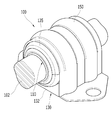
도 4 내지 도 7은 본 발명에 의한 스테빌라이저 바의 마운트 부시에 대한 일 실시예를 도시한 것으로서, 부호 100은 마운트 부시 전체를 지칭한다.4 to 7 illustrate an embodiment of a mount bush of a stabilizer bar according to the present invention, and
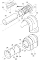
상기 마운트 부시(100)는 도 4 및 도 5에서와 같이, 인서트(110), 미끄럼 베어링(120), 고무부시(130), 브라켓(150)을 포함하여 이루어진다.4 and 5, the
상기에서 인서트(110)는 원통형 부재로서 플라스틱 재질로 이루어지며, 마운트하고자 하는 스테빌라이저 바(102)의 소정 위치 외주연에 직접 사출 형성된다.The
그리고 인서트(110)의 양단부에 대직경의 플랜지(111)(112)가 형성되며, 중앙의 외주연에는 소정의 둘레턱(113)이 형성되어 미끄럼 베어링(120)을 지지하는 역할을 수행하게 된다.In addition,
또한, 상기 둘레턱(113)과 양 플랜지(111)(112) 사이에는 일정 폭과 일정 깊이를 갖는 둘레홈(114)이 형성되어 윤활제인 그리스가 충전될 수 있도록 하였다. In addition, a
상기 인서트(110)와 슬립이 발생하며, 클램프 역할을 수행하는 상기 미끄럼 베어링(120)은 테프론 계열의 저마찰 소재{BI-MESH :테프론+동메쉬}로 이루어진다.The
상기 테프론 계열의 저마찰 소재는 경량화 및 조립성이 우수하다는 장점이 있고, 높은 내하중과 저 마찰계수, 낮은 열팽창, 열전도성, 성형성, 내화학성이 우수하다는 특징이 있다.The low friction material of the Teflon series has the advantages of light weight and excellent assembly, and has the characteristics of high load resistance, low coefficient of friction, low thermal expansion, thermal conductivity, moldability, and chemical resistance.
그리고 상기 미끄럼 베어링(120)은 좌,우 한쌍의 베어링(121)(122)으로 이루어지며, 상기 인서트(110)의 둘레턱(113)을 기준으로 양측에 배치되고, 양단부에는 상기 인서트(110)의 플랜지(111)(112) 보다 작은 플랜지(123)(124)가 형성되어 고부무시(130)를 고정시켜 주는 역할을 수행하게 된다.The sliding bearing 120 includes a pair of left and
또한, 상기 미끄럼 베어링(120)을 형성하는 좌,우 베어링(121)(122)은 축방향으로 소정 형태의 절개부(125)(126)에 의하여 오픈형으로 이루어져 상기 인서트(110)와의 조립이 용이하도록 구성된다.In addition, the left and
상기 미끄럼 베어링(120)의 외주측에 배치되는 고무부시(130)는 상,하 고무부재(131)(132)로 이루어지며, 내경부 안쪽 즉, 미끄럼 베어링(120)과 접촉되는 상,하 고무부재(131)(132)의 안쪽에는 내철(133)(134)이 매몰 형성되어 미끄럼 베어링(120)을 지지하게 된다.The
또한, 상기 고무부시(130)를 형성하는 상,하 고무부재(131)(132)의 양단부측면에는 이물질 침입 및 그리스 누유 방지를 위하여 도 6에서와 같이 립(Lip;135, 136)을 형성하였다. In addition, both ends of the upper and
상기 립(135)(136)을 형성함에 있어서는 립(135)(136)의 단부가 인서트(110)의 양 플랜지(111)(112)의 외경부와 강하게 탄성적으로 밀착이 이루어질 수 있도록 형성된다.In forming the
이를 위하여 본 발명에서는 상기 립(135)(136)의 뿌리부를 단부 보다 두껍게 형성하고, 립(135)(136)의 단부까지 상기 내철(133)(134)을 연장하여 매몰되도록 함으로써, 립(135)(136)의 강성을 확보토록 하였다.To this end, in the present invention, the root portion of the
또한, 도 7에서와 같이 상기 립(135)(136)의 단부 내경부에는 제1 시일링 턱(137)(138)을 형성하여 인서트(110)의 양 플랜지(111)(112) 외측 모서리 부분을 압착할 수 있도록 하였으며, 상기 양 플랜지(111)(112)의 외주면과 접촉되는 내경부에는 제2 시일링 턱(139)(140)을 형성하여 양 플랜지(111)(112)의 외주면에 형성된 시일링 홈(115)(116)에 안착될 수 있도록 하였다.In addition, as shown in FIG. 7, first sealing
이에 따라 상기 제1 시일링 턱(137)(138)이 외부로부터 침투하는 수분 및 이물질을 1차적으로 차단하게 되며, 상기 제2 시일링 턱(139)(140)이 인서트(110) 및 상,하 고무부재(131)(132)를 타고 침투하는 수분 및 이물질을 2차적으로 차단함과 동시에 누유를 방지함으로써, 완전한 시일링 성능을 확보할 수 있도록 하였다.Accordingly, the first sealing
상기 브라켓(150)은 차체 또는 서브 프레임(104)과 맞닿는 하측 고무부재(106)의 하면을 제외한 전체를 감싸는 형태로 이루어져 차체 또는 서브 프레임에 고정된다.The
이때 고무부시(130)의 외측면은 단면에서 볼 때 파형으로 형성하고, 브라켓(150) 또한 대응되는 파형 단면으로 형성함으로써, 고무부시(130)와 브라켓(150)의 고정력을 더욱 견고하게 하였다.At this time, the outer surface of the
이에 따라 상기와 같이 구성되는 마운트 부시(100)는 도 4 및 도 6과 같은 형태로 스테빌리이저 바(102)를 차체 또는 서브 프레임에 고정시켜 줄 수 있게 되는 것이다.Accordingly, the
그러면 인서트(110)가 스테빌라이저 바(102)에 직접 사출하는 방식으로 제작되는 바, 스테빌라이저 바(102)의 이탈 방지용 클램프 역할을 수행하고, 중앙 둘레턱(113)에 의하여 미끄럼 베어링(120)의 이탈을 방지할 수 있게 되는 것이다. Then, the
그리고 인서트(110)와 미끄럼 베어링(120) 사이에 윤활제인 그리스가 충전되는 바, 전 거동 구간 마찰을 최소화할 수 있게 되며, 기동 토크 구간의 최소화로 소음 발생을 방지할 수 있게 된다.And the grease which is a lubricant is filled between the
또한, 미끄럼 베어링(120)이 한쌍의 좌,우 베어링(121)(122)으로 이루어짐과 동시에 오픈형으로 이루어짐으로써, 공차 관리 및 조립성이 향상된다.In addition, since the sliding
그리고 고무부시(130)의 내경부에 내철(133)(134)이 적용됨으로써, 미끄럼 베어링(120)을 변형없는 형태로 고정시켜주게 되며, 특히 상기 립(135)(136)에 의하여 재1, 2 시일링 턱(137)(138),(139)(140)에 의하여 이물질 침투 및 그리스 누유를 방지할 수 있는 바, 미끄럼 베어링(120)의 성능 저하를 방지할 수 있게 된다.And by applying the
또한, 내철(133)(134)이 립(135)(136) 부분까지 연장되어 립(135)(136)을 지지하여 주게 되는 바, 차량의 롤 거동시 립(135)(136)의 변형을 최소화할 수 있게 되는 시일링 효과를 높일 수 있게 되는 것이다.In addition, the
그리고 상기의 구성에 의하여 고무부재의 두께를 축소할 수 있는 바, 고무부재의 노화에 따른 고무부재의 경화 영향도 축소되어 소음 발생을 줄일 수 있게 된다.In addition, by the above configuration, the thickness of the rubber member can be reduced, and the effect of hardening of the rubber member due to aging of the rubber member is also reduced to reduce the occurrence of noise.
이상을 통해 본 발명의 바람직한 실시예에 대하여 설명하였지만, 본 발명은 이에 한정되는 것이 아니고 특허청구범위와 발명의 상세한 설명 및 첨부한 도면의 범위 안에서 여러 가지로 변형하여 실시하는 것이 가능하고 이 또한 본 발명의 범위에 속하는 것은 당연하다.Although the preferred embodiments of the present invention have been described above, the present invention is not limited thereto, and various modifications and changes can be made within the scope of the claims and the detailed description of the invention and the accompanying drawings. Naturally, it belongs to the scope of the invention.
100...마운트 부시 102...스테빌리이저 바
110...인서트 111,112,123,124...플랜지
113...둘레턱 114...둘레홈
115,116...시일링 홈 120...미끄럼 베어링
121,122...좌,우 베어링 125,126...절개부
130...고무부시 131,132...상,하 고무부재
133,134...내철 135,136...립
137,138...제1 시일링 턱 139,140...제2 시일링 턱100 ... mount
110 ... Insert 111,112,123,124 ... Flange
113 ...
115,116 ... seal
121,122 ... left and right bearings 125,126 ... incisions
130 ... rubber bush 131,132 ... upper / lower rubber member
133,134 Staples 135,136
137,138 ... 1st sealing jaw 139,140 ... 2nd sealing jaw
Claims (8)
스테빌라이저 바(102)의 고정부위에 직접 사출 형성되는 인서트(110)와;
좌,우 한쌍의 베어링(121)(122)으로 이루어져 상기 인서트(110)의 외주면에 윤활층을 가지고 결합되는 미끄럼 베어링(120)과;
상,하 고무부재(131)(132)로 이루어져 상기 미끄럼 베어링(120)의 외주측을 감싸는 형태로 결합되며, 양단부에 2차 시일링이 이루어지는 시일링 구조를 갖는 고무부시(130)와;
상기 고무부시(130)를 감싸면서 서브 프레임(차체)에 고정되는 브라켓(140)을 포함하여 이루어짐을 특징으로 하는 자동차용 스테빌라이저 바의 마운트 부시.In forming the mount bush 100 for fixing both sides of the straight portion of the stabilizer bar 102 to the sub-frame (car body) 104,
An insert 110 which is directly injection-molded at the fixed portion of the stabilizer bar 102;
A sliding bearing 120 having a left and right pair of bearings 121 and 122 coupled to the outer circumferential surface of the insert 110 with a lubricating layer;
A rubber bush 130 having upper and lower rubber members 131 and 132 coupled to surround the outer circumferential side of the sliding bearing 120 and having a sealing structure in which secondary sealing is made at both ends;
Mounting bush of the stabilizer bar for a vehicle, characterized in that made of a rubber bush 130, including a bracket 140 is fixed to the sub-frame (car body).
Priority Applications (1)
| Application Number | Priority Date | Filing Date | Title |
|---|---|---|---|
| KR1020100070996A KR101592349B1 (en) | 2010-07-22 | 2010-07-22 | Mount bush of stabilizer bar for vehicle |
Applications Claiming Priority (1)
| Application Number | Priority Date | Filing Date | Title |
|---|---|---|---|
| KR1020100070996A KR101592349B1 (en) | 2010-07-22 | 2010-07-22 | Mount bush of stabilizer bar for vehicle |
Publications (2)
| Publication Number | Publication Date |
|---|---|
| KR20120009132A true KR20120009132A (en) | 2012-02-01 |
| KR101592349B1 KR101592349B1 (en) | 2016-02-11 |
Family
ID=45834083
Family Applications (1)
| Application Number | Title | Priority Date | Filing Date |
|---|---|---|---|
| KR1020100070996A KR101592349B1 (en) | 2010-07-22 | 2010-07-22 | Mount bush of stabilizer bar for vehicle |
Country Status (1)
| Country | Link |
|---|---|
| KR (1) | KR101592349B1 (en) |
Cited By (3)
| Publication number | Priority date | Publication date | Assignee | Title |
|---|---|---|---|---|
| KR101315678B1 (en) * | 2012-10-16 | 2013-10-08 | 대원강업주식회사 | Bush for mounting stabilizer bar for vehicle |
| KR101454906B1 (en) * | 2013-04-23 | 2014-11-04 | 주식회사 일진 | Torsion bar supporting unit and manufacturing method thereof |
| KR20160076029A (en) * | 2014-12-22 | 2016-06-30 | 주식회사 센트랄 | Bush and Method for manufacturing the bush |
Families Citing this family (1)
| Publication number | Priority date | Publication date | Assignee | Title |
|---|---|---|---|---|
| KR102213288B1 (en) | 2019-01-26 | 2021-02-05 | 장순길 | Stabilizer for vehicle |
Citations (4)
| Publication number | Priority date | Publication date | Assignee | Title |
|---|---|---|---|---|
| KR20050008351A (en) * | 2003-07-15 | 2005-01-21 | 현대자동차주식회사 | mounting apparatus of stabilizer |
| US20050286821A1 (en) * | 2004-06-28 | 2005-12-29 | Zf Friedrichshafen Ag | Annular disk for a sliding bearing |
| JP2006076410A (en) * | 2004-09-08 | 2006-03-23 | Mitsubishi Fuso Truck & Bus Corp | Suspension structure of vehicle equipped with multi-layer bushing |
| JP2010023642A (en) * | 2008-07-18 | 2010-02-04 | Nhk Spring Co Ltd | Stabilizer device |
-
2010
- 2010-07-22 KR KR1020100070996A patent/KR101592349B1/en active IP Right Grant
Patent Citations (4)
| Publication number | Priority date | Publication date | Assignee | Title |
|---|---|---|---|---|
| KR20050008351A (en) * | 2003-07-15 | 2005-01-21 | 현대자동차주식회사 | mounting apparatus of stabilizer |
| US20050286821A1 (en) * | 2004-06-28 | 2005-12-29 | Zf Friedrichshafen Ag | Annular disk for a sliding bearing |
| JP2006076410A (en) * | 2004-09-08 | 2006-03-23 | Mitsubishi Fuso Truck & Bus Corp | Suspension structure of vehicle equipped with multi-layer bushing |
| JP2010023642A (en) * | 2008-07-18 | 2010-02-04 | Nhk Spring Co Ltd | Stabilizer device |
Cited By (3)
| Publication number | Priority date | Publication date | Assignee | Title |
|---|---|---|---|---|
| KR101315678B1 (en) * | 2012-10-16 | 2013-10-08 | 대원강업주식회사 | Bush for mounting stabilizer bar for vehicle |
| KR101454906B1 (en) * | 2013-04-23 | 2014-11-04 | 주식회사 일진 | Torsion bar supporting unit and manufacturing method thereof |
| KR20160076029A (en) * | 2014-12-22 | 2016-06-30 | 주식회사 센트랄 | Bush and Method for manufacturing the bush |
Also Published As
| Publication number | Publication date |
|---|---|
| KR101592349B1 (en) | 2016-02-11 |
Similar Documents
| Publication | Publication Date | Title |
|---|---|---|
| KR101550598B1 (en) | Mount bush of stabilizer bar for vehicle | |
| KR20130014237A (en) | Mount bush of stabilizer bar for vehicle | |
| US8292312B2 (en) | Stabilizer bushing for vehicle | |
| KR101592347B1 (en) | Mount bush of stabilizer bar for vehicle | |
| RU2531205C2 (en) | Articulated and/or bearing assembly with elastic gasket | |
| US9546705B2 (en) | Bush | |
| US8434770B2 (en) | Transverse link on a motor vehicle | |
| KR20120009132A (en) | Mount bush of stabilizer bar for vehicle | |
| JP2008127014A (en) | Bump stopper for control torque, and suspension leg of steering wheel for automobile | |
| CN102171484A (en) | Vibration-damping rubber member and process for producing same | |
| KR20110132744A (en) | Mount bush of stabilizer bar for vehicle | |
| KR101322426B1 (en) | Pillow ball bush for vehicle | |
| KR101791555B1 (en) | Mounting bush for stabilizer bar | |
| KR20120015195A (en) | Mount bush of stabilizer bar for vehicle | |
| JP2010054017A (en) | Vibration absorbing device | |
| CN105102246B (en) | For the vehicle bridge guide bearing being coupled in back axle on the vehicle structure of motor vehicle | |
| KR20110132743A (en) | Mount bush of stabilizer bar for vehicle | |
| US20180281578A1 (en) | Roll restrictor system for an automotive powertrain | |
| US10227089B2 (en) | Front axle of vehicle capable of reducing vibration | |
| KR20210062133A (en) | Bush apparatus of stabilizerbar for vehicle | |
| KR20200111852A (en) | Bush apparatus of stabilizerbar for vehicle | |
| JP3704422B2 (en) | Steering bush | |
| KR20120012207A (en) | Mount bush of stabilizer bar for vehicle | |
| KR102463446B1 (en) | Stabilizer bush | |
| US7878462B1 (en) | Cable constraining device for reduced cable wear |
Legal Events
| Date | Code | Title | Description |
|---|---|---|---|
| A201 | Request for examination | ||
| E902 | Notification of reason for refusal | ||
| E701 | Decision to grant or registration of patent right | ||
| GRNT | Written decision to grant | ||
| FPAY | Annual fee payment |
Payment date: 20190130 Year of fee payment: 4 |