KR20120006984A - Galvanic cell having a frame and method for the production of said galvanic cell - Google Patents
Galvanic cell having a frame and method for the production of said galvanic cell Download PDFInfo
- Publication number
- KR20120006984A KR20120006984A KR1020117022491A KR20117022491A KR20120006984A KR 20120006984 A KR20120006984 A KR 20120006984A KR 1020117022491 A KR1020117022491 A KR 1020117022491A KR 20117022491 A KR20117022491 A KR 20117022491A KR 20120006984 A KR20120006984 A KR 20120006984A
- Authority
- KR
- South Korea
- Prior art keywords
- cell
- frame
- package
- cells
- galvanic
- Prior art date
Links
Images


Classifications
-
- H—ELECTRICITY
- H01—ELECTRIC ELEMENTS
- H01M—PROCESSES OR MEANS, e.g. BATTERIES, FOR THE DIRECT CONVERSION OF CHEMICAL ENERGY INTO ELECTRICAL ENERGY
- H01M10/00—Secondary cells; Manufacture thereof
- H01M10/04—Construction or manufacture in general
- H01M10/0413—Large-sized flat cells or batteries for motive or stationary systems with plate-like electrodes
-
- H—ELECTRICITY
- H01—ELECTRIC ELEMENTS
- H01M—PROCESSES OR MEANS, e.g. BATTERIES, FOR THE DIRECT CONVERSION OF CHEMICAL ENERGY INTO ELECTRICAL ENERGY
- H01M50/00—Constructional details or processes of manufacture of the non-active parts of electrochemical cells other than fuel cells, e.g. hybrid cells
- H01M50/10—Primary casings, jackets or wrappings of a single cell or a single battery
- H01M50/102—Primary casings, jackets or wrappings of a single cell or a single battery characterised by their shape or physical structure
- H01M50/105—Pouches or flexible bags
-
- H—ELECTRICITY
- H01—ELECTRIC ELEMENTS
- H01M—PROCESSES OR MEANS, e.g. BATTERIES, FOR THE DIRECT CONVERSION OF CHEMICAL ENERGY INTO ELECTRICAL ENERGY
- H01M50/00—Constructional details or processes of manufacture of the non-active parts of electrochemical cells other than fuel cells, e.g. hybrid cells
- H01M50/10—Primary casings, jackets or wrappings of a single cell or a single battery
- H01M50/116—Primary casings, jackets or wrappings of a single cell or a single battery characterised by the material
- H01M50/117—Inorganic material
- H01M50/119—Metals
-
- H—ELECTRICITY
- H01—ELECTRIC ELEMENTS
- H01M—PROCESSES OR MEANS, e.g. BATTERIES, FOR THE DIRECT CONVERSION OF CHEMICAL ENERGY INTO ELECTRICAL ENERGY
- H01M50/00—Constructional details or processes of manufacture of the non-active parts of electrochemical cells other than fuel cells, e.g. hybrid cells
- H01M50/10—Primary casings, jackets or wrappings of a single cell or a single battery
- H01M50/116—Primary casings, jackets or wrappings of a single cell or a single battery characterised by the material
- H01M50/121—Organic material
-
- H—ELECTRICITY
- H01—ELECTRIC ELEMENTS
- H01M—PROCESSES OR MEANS, e.g. BATTERIES, FOR THE DIRECT CONVERSION OF CHEMICAL ENERGY INTO ELECTRICAL ENERGY
- H01M50/00—Constructional details or processes of manufacture of the non-active parts of electrochemical cells other than fuel cells, e.g. hybrid cells
- H01M50/10—Primary casings, jackets or wrappings of a single cell or a single battery
- H01M50/116—Primary casings, jackets or wrappings of a single cell or a single battery characterised by the material
- H01M50/124—Primary casings, jackets or wrappings of a single cell or a single battery characterised by the material having a layered structure
- H01M50/126—Primary casings, jackets or wrappings of a single cell or a single battery characterised by the material having a layered structure comprising three or more layers
-
- H—ELECTRICITY
- H01—ELECTRIC ELEMENTS
- H01M—PROCESSES OR MEANS, e.g. BATTERIES, FOR THE DIRECT CONVERSION OF CHEMICAL ENERGY INTO ELECTRICAL ENERGY
- H01M50/00—Constructional details or processes of manufacture of the non-active parts of electrochemical cells other than fuel cells, e.g. hybrid cells
- H01M50/10—Primary casings, jackets or wrappings of a single cell or a single battery
- H01M50/172—Arrangements of electric connectors penetrating the casing
- H01M50/174—Arrangements of electric connectors penetrating the casing adapted for the shape of the cells
- H01M50/178—Arrangements of electric connectors penetrating the casing adapted for the shape of the cells for pouch or flexible bag cells
-
- H—ELECTRICITY
- H01—ELECTRIC ELEMENTS
- H01M—PROCESSES OR MEANS, e.g. BATTERIES, FOR THE DIRECT CONVERSION OF CHEMICAL ENERGY INTO ELECTRICAL ENERGY
- H01M50/00—Constructional details or processes of manufacture of the non-active parts of electrochemical cells other than fuel cells, e.g. hybrid cells
- H01M50/20—Mountings; Secondary casings or frames; Racks, modules or packs; Suspension devices; Shock absorbers; Transport or carrying devices; Holders
- H01M50/204—Racks, modules or packs for multiple batteries or multiple cells
- H01M50/207—Racks, modules or packs for multiple batteries or multiple cells characterised by their shape
- H01M50/211—Racks, modules or packs for multiple batteries or multiple cells characterised by their shape adapted for pouch cells
-
- H—ELECTRICITY
- H01—ELECTRIC ELEMENTS
- H01M—PROCESSES OR MEANS, e.g. BATTERIES, FOR THE DIRECT CONVERSION OF CHEMICAL ENERGY INTO ELECTRICAL ENERGY
- H01M50/00—Constructional details or processes of manufacture of the non-active parts of electrochemical cells other than fuel cells, e.g. hybrid cells
- H01M50/20—Mountings; Secondary casings or frames; Racks, modules or packs; Suspension devices; Shock absorbers; Transport or carrying devices; Holders
- H01M50/258—Modular batteries; Casings provided with means for assembling
-
- H—ELECTRICITY
- H01—ELECTRIC ELEMENTS
- H01M—PROCESSES OR MEANS, e.g. BATTERIES, FOR THE DIRECT CONVERSION OF CHEMICAL ENERGY INTO ELECTRICAL ENERGY
- H01M50/00—Constructional details or processes of manufacture of the non-active parts of electrochemical cells other than fuel cells, e.g. hybrid cells
- H01M50/50—Current conducting connections for cells or batteries
- H01M50/543—Terminals
- H01M50/547—Terminals characterised by the disposition of the terminals on the cells
- H01M50/55—Terminals characterised by the disposition of the terminals on the cells on the same side of the cell
-
- H—ELECTRICITY
- H01—ELECTRIC ELEMENTS
- H01M—PROCESSES OR MEANS, e.g. BATTERIES, FOR THE DIRECT CONVERSION OF CHEMICAL ENERGY INTO ELECTRICAL ENERGY
- H01M50/00—Constructional details or processes of manufacture of the non-active parts of electrochemical cells other than fuel cells, e.g. hybrid cells
- H01M50/50—Current conducting connections for cells or batteries
- H01M50/543—Terminals
- H01M50/552—Terminals characterised by their shape
- H01M50/553—Terminals adapted for prismatic, pouch or rectangular cells
- H01M50/557—Plate-shaped terminals
-
- Y—GENERAL TAGGING OF NEW TECHNOLOGICAL DEVELOPMENTS; GENERAL TAGGING OF CROSS-SECTIONAL TECHNOLOGIES SPANNING OVER SEVERAL SECTIONS OF THE IPC; TECHNICAL SUBJECTS COVERED BY FORMER USPC CROSS-REFERENCE ART COLLECTIONS [XRACs] AND DIGESTS
- Y02—TECHNOLOGIES OR APPLICATIONS FOR MITIGATION OR ADAPTATION AGAINST CLIMATE CHANGE
- Y02E—REDUCTION OF GREENHOUSE GAS [GHG] EMISSIONS, RELATED TO ENERGY GENERATION, TRANSMISSION OR DISTRIBUTION
- Y02E60/00—Enabling technologies; Technologies with a potential or indirect contribution to GHG emissions mitigation
- Y02E60/10—Energy storage using batteries
-
- Y—GENERAL TAGGING OF NEW TECHNOLOGICAL DEVELOPMENTS; GENERAL TAGGING OF CROSS-SECTIONAL TECHNOLOGIES SPANNING OVER SEVERAL SECTIONS OF THE IPC; TECHNICAL SUBJECTS COVERED BY FORMER USPC CROSS-REFERENCE ART COLLECTIONS [XRACs] AND DIGESTS
- Y02—TECHNOLOGIES OR APPLICATIONS FOR MITIGATION OR ADAPTATION AGAINST CLIMATE CHANGE
- Y02P—CLIMATE CHANGE MITIGATION TECHNOLOGIES IN THE PRODUCTION OR PROCESSING OF GOODS
- Y02P70/00—Climate change mitigation technologies in the production process for final industrial or consumer products
- Y02P70/50—Manufacturing or production processes characterised by the final manufactured product
-
- Y—GENERAL TAGGING OF NEW TECHNOLOGICAL DEVELOPMENTS; GENERAL TAGGING OF CROSS-SECTIONAL TECHNOLOGIES SPANNING OVER SEVERAL SECTIONS OF THE IPC; TECHNICAL SUBJECTS COVERED BY FORMER USPC CROSS-REFERENCE ART COLLECTIONS [XRACs] AND DIGESTS
- Y10—TECHNICAL SUBJECTS COVERED BY FORMER USPC
- Y10T—TECHNICAL SUBJECTS COVERED BY FORMER US CLASSIFICATION
- Y10T29/00—Metal working
- Y10T29/49—Method of mechanical manufacture
- Y10T29/49002—Electrical device making
- Y10T29/49108—Electric battery cell making
Abstract
막 형태의 패키지를 가진 전극 스택으로 이루어지고 상기 패키지로부터 2개 이상의 전도체들이 돌출되는 갈바닉 셀용 프레임은 셀의 제조시 셀의 패키지와 견고하게 결합될 수 있도록 형성된다. 이러한 갈바닉 셀의 제조시, 프레임은 패키지의 폐쇄시 패키지와 견고하게 결합된다. The galvanic cell frame, consisting of an electrode stack with a package in the form of a film and from which two or more conductors protrude from the package, is formed to be firmly coupled to the cell's package in the manufacture of the cell. In the manufacture of such galvanic cells, the frame is firmly engaged with the package upon closure of the package.
Description
본 발명은 프레임을 구비한 갈바닉 셀 및 이 갈바닉 셀의 제조 방법에 관한 것이다. 직사각형 플랫 셀들(배터리 셀들, 커패시터들 등)이 공지되어 있으며, 상기 셀의 전기 화학적으로 작용하는 내용물은 2면이 플라스틱 코팅된 예컨대 얇은 알루미늄 막과 같은 막 형태의 패키지에 의해 둘러싸이고, 상기 패키지를 통해 플레이트 형태의 전기 연결부들(소위 "전도체")이 안내된다. 다른 셀 구조들과는 달리, 이러한 셀들의 패키지는 전기 전도성을 갖지 않는데, 왜냐하면 전도체들은 절연 상태로 패키지를 통해 안내되기 때문이다. 이렇게 구성된 배터리 셀들은 파우치- 또는 커피 백-셀들이라고도 한다. The present invention relates to a galvanic cell with a frame and a method for producing the galvanic cell. Rectangular flat cells (battery cells, capacitors, etc.) are known and the electrochemically working contents of the cell are surrounded by a package in the form of a film such as a thin aluminum film coated on two sides with a plastic coating, The electrical connections in the form of plates (so-called "conductors") are guided through. Unlike other cell structures, the package of these cells is not electrically conductive because the conductors are guided through the package in an insulated state. The battery cells thus configured are also called pouch- or coffee bag-cells.
예컨대 전기 자동차 또는 하이브리드 자동차에서 다양하게 적용되는 경우, 개별 갈바닉 셀들이 직렬 또는 병렬 접속되고 종종 관련 전자 장치와 함께 하나의 하우징 내에 놓인다. 막 내로 용접되는 파우치 셀들의 종종 매우 크지 않은 기계적 부하 용량으로 인해, 상기 파우치 셀들이 종종 배터리 하우징 내로 직접 조립될 수 없고 먼저 적합한 지지 구조물들에 의해 기계적으로 안정화되어야 한다.In various applications, for example in electric or hybrid vehicles, the individual galvanic cells are connected in series or in parallel and are often placed in one housing together with the associated electronics. Due to the often not very large mechanical load capacity of the pouch cells welded into the membrane, the pouch cells often cannot be assembled directly into the battery housing and must first be mechanically stabilized by suitable supporting structures.
본 발명의 과제는 갈바닉 셀들의 사용 및 처리를 용이하게 하고, 상기 갈바닉 셀의 패키지 막의 민감성과 관련된 문제를 완화하거나 가능한 해결하는 것이다.The problem of the present invention is to facilitate the use and processing of galvanic cells and to mitigate or possibly solve the problems associated with the sensitivity of the package film of the galvanic cells.
상기 과제는 독립 청구항들 중 하나에 따른 프레임, 갈바닉 셀 또는 그 제조 방법에 의해 달성될 수 있다.This object can be achieved by a frame, a galvanic cell or a method of manufacturing the same according to one of the independent claims.
본 발명에 따라, 갈바닉 셀용 프레임이 제공된다. 셀은 실질적으로 전극 스택 및 막 형태의 패키지로 이루어지고, 상기 패키지로부터 2개 이상의 전도체들이 돌출한다. 프레임은 셀의 제조시 셀의 패키지와 견고하게 결합될 수 있도록 형성된다. 갈바닉 셀의 제조를 위한 본 발명에 따른 방법에서, 패키지의 폐쇄시 프레임이 패키지와 견고하게 결합된다. According to the invention, a frame for a galvanic cell is provided. The cell consists essentially of a package in the form of an electrode stack and a film, from which two or more conductors protrude. The frame is formed to be firmly coupled to the package of the cell in the manufacture of the cell. In the method according to the invention for the production of galvanic cells, the frame is rigidly coupled with the package upon closing of the package.
하기에는 발명의 이하 설명에서 사용되는 표현들이 설명된다.In the following, the expressions used in the following description of the invention are described.
적층 스택은 모든 방식의 갈바닉 셀의 전기 화학적으로 작용하는 내용물에 대한 표현으로서 사용된다. 반대로, 셀의 패키지는 전극 스택을 주변으로부터 폐쇄하는, 전기 화학적 반응에 참여하지 않는 재료이다.Stacked stacks are used as a representation of the electrochemically acting content of galvanic cells in all manner. In contrast, a package of cells is a material that does not participate in an electrochemical reaction, which closes the electrode stack from the surroundings.
막 형태의 패키지는, 바람직하게는 적은 량의 재료를 사용해서 전극 스택을 주변으로부터 효과적으로 차단하고 폐쇄하는 목적을 달성하는 모든 형태의 패키지들 또는 포함물이다. 폐쇄는 재료 및 전류의 전달을 막아야 한다. 상기 표현은 일반적 막뿐 아니라 특히 플라스틱 코팅된 금속 막도 포함한다.Packages in the form of membranes are preferably all forms of packages or inclusions which serve the purpose of effectively shielding and closing the electrode stack from the surroundings using a small amount of material. The closure should prevent the transfer of material and current. The expression includes not only general membranes but also especially plastic coated metal membranes.
본 발명에서 전도체는 패키지를 통해 외부로 안내됨으로써 셀 내로 또는 셀 밖으로 전하의 전달이 이루어지는 전기 컨덕터이다. In the present invention, a conductor is an electrical conductor through which a charge is transferred into or out of a cell by being guided out through the package.
본 발명에서 프레임은 셀을 주변 영향에 대해 기계적으로 안정화하기에 적합하고 셀의 제조시 셀의 패키지와 견고하게 결합될 수 있는 모든 구조적 장치이다. 전술 했듯이, 프레임은 갈바닉 셀을 기계적으로 안정화시키는 기능을 실질적으로 하는 바람직하게는 실질적으로 프레임 형태의 장치이다.In the present invention, the frame is any structural device suitable for mechanically stabilizing the cell against ambient influences and capable of being rigidly coupled with the package of the cell in the manufacture of the cell. As mentioned above, the frame is preferably a substantially frame-shaped device that substantially serves to mechanically stabilize the galvanic cell.
이하에는 본 발명이 바람직한 실시예들 및 도면들을 참조로 더 자세히 설명된다.The invention is described in more detail below with reference to preferred embodiments and figures.
본 발명에 의해, 갈바닉 셀들의 사용 및 처리가 용이해지고, 패키지 막의 민감성과 관련된 문제가 완화되고 가능한 해결될 수 있다. With the present invention, the use and processing of galvanic cells is facilitated, and the problems associated with the sensitivity of the package film can be alleviated and possibly solved.
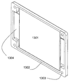
도 1은 통합된 프레임을 갖는 본 발명에 따른 셀의 실시예의 정면도.
도 2는 동일 실시예의 배면도.
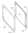
도 3은 상기 셀의 정면 분해도.
도 4는 상기 셀의 배면 분해도.
도 5는 프레임이 외부로 연장되는 패키지 막의 내부면과 용접되는 본 발명의 실시예.
도 6은 프레임이 2개의 막들의 실링 영역에서 프레임이 패키지 막의 외부면과 용접되는 본 발명의 실시예.
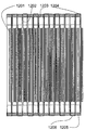
도 7은 갈바닉 셀들의 전형적 패키지 막의 일반적 구성.
도 8은 본 발명의 실시예에 따른 갈바닉 셀들로 이루어진 셀 블록의 구성.
도 9는 타이 로드용 홀을 가진 프레임, 및 프레임 둘레에서 부분적으로 휘어져서 압력 끼워 맞춤식으로 접촉되는 전도체들을 포함한 본 발명의 실시예에 따른 갈바닉 셀.
도 10은 도 9에 도시된 셀의 분해도.
도 11은 타이 로드가 도시되지 않은 개별 셀들로 이루어진 셀 블록.
도 12는 도 11에 도시된 셀 블록의 단면도.
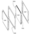
도 13은 전도체들이 막의 용접을 위해 서로 평행하게 돌출되고 압력 끼워 맞춤식으로 접촉되는 다른 실시예에 따른 본 발명에 따른 셀.
도 14는 도 13에 도시된 셀의 분해도.
도 15는 상기 셀의 다른 분해도.
도 16은 본 발명의 실시예에 따른 갈바닉 셀의 다양한 단면도들.
도 17은 본 발명의 실시예에 따른 셀의 프레임 영역이 확대된 단면도.
도 18은 도 13에 따른 셀들로 이루어진 셀 블록.
도 19는 도 20에 도시되는 단면도의 절개를 설명하기 위한 단면도 및 도 16에 도시되는 단면도들의 절개를 설명하기 위한 다른 단면도.
도 20은 도 18에 도시된 셀 블록의 단면도.
도 21은 도 20의 확대 부분도. 1 is a front view of an embodiment of a cell according to the invention with an integrated frame;
2 is a rear view of the same embodiment.
3 is a front exploded view of the cell;
4 is a rear exploded view of the cell;
5 is an embodiment of the invention in which the frame is welded with the inner surface of the package membrane extending outwardly.
6 shows an embodiment of the invention in which the frame is welded with the outer surface of the package membrane in the sealing region of the two membranes.
7 is a general configuration of a typical package film of galvanic cells.
8 is a configuration of a cell block consisting of galvanic cells according to an embodiment of the present invention.
9 shows a galvanic cell in accordance with an embodiment of the present invention comprising a frame having a tie rod hole, and conductors that are partially bent around the frame and are in pressure fit contact.
10 is an exploded view of the cell shown in FIG. 9;
Fig. 11 is a cell block made up of individual cells with no tie rods shown.
12 is a cross-sectional view of the cell block shown in FIG.
13 is a cell according to the invention according to another embodiment in which the conductors protrude parallel to each other and are pressure-fitted in contact with each other for welding of the membrane.
14 is an exploded view of the cell shown in FIG. 13;
15 is another exploded view of the cell.
16 shows various cross-sectional views of a galvanic cell in accordance with an embodiment of the present invention.
17 is an enlarged cross-sectional view of a frame region of a cell according to an embodiment of the present invention.
18 is a cell block consisting of the cells according to FIG.
FIG. 19 is a sectional view for explaining the sectional view shown in FIG. 20 and another sectional view for illustrating the sectional views shown in FIG. 16;
20 is a sectional view of the cell block shown in FIG. 18;
21 is an enlarged partial view of FIG. 20;
본 발명은 막 형태의 패키지를 가진 전극 스택으로 실질적으로 이루어지고 상기 패키지로부터 2개 이상의 전도체들이 돌출하는 갈바닉 셀에 관한 것이다. 본 발명에 따라, 이러한 갈바닉 셀은 셀의 제조시 셀의 패키지와 견고하게 결합될 수 있게 형성되는 프레임에 의해 안정화된다. 본 발명의 몇몇의 실시예들이 적합하게 형성되면, 갈바닉 셀이 배터리 내로의 조립시에야 비로소 프레임 또는 틀과의 결합에 의해서 안정화되는 것이 아니라, 셀이 셀 블록 내로 조립 전에 이미 본 발명에 따른 프레임에 의해 안정화되는 장점을 갖는다. 결과적으로 프레임이 패키지의 폐쇄시 이미 셀과 결합되는 본 발명에 따른 방법은 셀이 다른 제조 공정 동안, 즉 충전, 성형, 계획에 따른 에이징("에이징") 또는 소위 "그레이딩" 동안 기계적 영향으로부터 보호되는 장점도 갖는다.The present invention relates to a galvanic cell consisting essentially of an electrode stack with a package in the form of a membrane, from which two or more conductors protrude from the package. According to the invention, these galvanic cells are stabilized by a frame which is formed to be firmly coupled with the package of the cell in the manufacture of the cell. When some embodiments of the present invention are suitably formed, the galvanic cell is not stabilized by engagement with the frame or frame until assembly into the battery, but before the cell is assembled into the cell block, It has the advantage of being stabilized by. As a result, the method according to the invention, in which the frame is already associated with the cell upon closure of the package, protects the cell from mechanical influences during other manufacturing processes, ie during filling, molding, planned aging ("aging") or so-called "grading". It also has the advantage of being.
셀의 본 발명에 따른 프레임 결합을 형성하기 위해 용도에 따라 예컨대 접착과 같은 소재 결합식 방법 또는 유사한 방법이 적합하다. 바람직하게 프레임은 접합 파트너들 사이에 있는 열 가소성 층의 부분적인 용융 및 압력 하에서 후속 냉각에 의해 이루어지는 고온 프레스 또는 고온 실링에 의해 패키지 막과 결합될 수 있고, 상기 패키지 막에는 종종 상응하는 적합한 코팅이 주어진다.Depending on the application, a material-bonded method or similar method is suitable for forming the frame bond according to the invention of the cell, for example. Preferably the frame can be combined with the package membrane by a hot press or a high temperature seal made by subsequent cooling under partial melting and pressure of the thermoplastic layer between the bonding partners, the package membrane often having a corresponding suitable coating. Is given.
고온 실링이라는 표현은 패키지 재료들(예컨대 결합 막들)의 열 가소성 용융 층들을 바람직하게는 고온 프레스에 의해 결합하는 방법이다. 고온 실링은 패키기 기술에서 막들의 용접에 중요한 방법이다. 실질적으로 하기 2가지 방식으로 구분된다. The expression hot sealing is a method of joining thermoplastic melt layers of package materials (eg bonding films), preferably by hot pressing. High temperature sealing is an important method for the welding of membranes in packaging technology. Substantially, it is divided into two ways.
a) 콘택 실링이라고도 하는, 실링 플랜지들 간의 고온 로드 또는 고온 스페이서에 의한 실링.a) Sealing by hot rods or hot spacers between the sealing flanges, also called contact sealing.
b) 임펄스(impulse) 실링.b) impulse sealing.
첫번째 방식에서 바람직하게는 이동하는 실링 플랜지가 가열된 로드를 포함한다. 바람직하게는 고정된 하부 실링 플랜지에 탄성 재료로 이루어진 표면이 종종 제공됨으로써, 실링 시임의 울퉁불퉁함이 보상된다. 이러한 방식의 실링 엘리먼트들은 파우치(패키지)의 제조 및 폐쇄를 위한 여러 구매 가능한 기계들에서, 그리고 성형-, 충전-, 및 폐쇄-기계들에서 사용된다.In the first manner the moving sealing flange preferably comprises a heated rod. Preferably the surface of the elastic material is preferably provided on the fixed lower sealing flange, thereby compensating for the irregularities of the sealing seam. Sealing elements in this manner are used in various commercially available machines for the manufacture and closure of pouches (packages) and in forming-, filling- and closing-machines.
실링 시임이 매우 긴 경우, 모든 실링 면에 걸쳐 동일한 압력을 보장하기 위해 고온 로드들은 사이즈가 아주 정확하고 편차 없이 가공되어야 한다. 더 깨끗한 실링 시임들을 얻기 위해 막들은 실링 공구 내로 도입되기 전에 스트레칭 장치들에 의해 평편해진다. 다른 가능성은 톱형 실링 면을 가진 고온 로드들의 사용이지만, 이 경우 홀을 형성할 위험이 있다.If the sealing seam is very long, the hot rods must be very accurate in size and machined without deviation to ensure the same pressure across all sealing surfaces. The membranes are flattened by stretching devices before they are introduced into the sealing tool to obtain cleaner sealing seams. Another possibility is the use of hot rods with a top sealing face, but in this case there is a risk of forming a hole.
고정된, 차가운 실링 플랜지의 탄성 표면을 위해서는 실리콘 고무가 바람직한 것으로 나타났다. 대응 압력 빔은 종종 조금 볼록한 형태를 갖는다. 실링 과정 동안 실링 시임의 중간에서 먼저 압력이 형성되고 상기 압력이 공구의 폐쇄시 테두리로 퍼진다. 이렇게 최적의 실링 시임이 형성된다. 또한, 수증기의 생성에 의해 실링 시임을 손상시킬 수 있는 작은 액체 방울들은 실링 영역으로부터 밀려나온다.Silicone rubber has been shown to be desirable for the elastic surface of fixed, cold sealing flanges. Corresponding pressure beams often have a slightly convex shape. During the sealing process a pressure is first established in the middle of the sealing seam and the pressure spreads to the rim upon closing of the tool. Thus an optimal sealing seam is formed. In addition, small liquid droplets that can damage the sealing seam by the generation of water vapor are pushed out of the sealing area.
임펄스 실링의 경우, 실링 빔들의 온도가 잠시 동안만 유지되고 전체 실링 사이클 동안 유지되지 않는다. 필요한 열은 2개의 실링 플랜지들 상의 2개의 작은 저항 소자들에 의해 형성된다.In the case of impulse sealing, the temperature of the sealing beams is only maintained for a while and not for the entire sealing cycle. The required heat is formed by two small resistance elements on the two sealing flanges.
실링 공구가 실링될 막에 걸쳐 폐쇄되면, 짧은 전류 펄스에 의해 용접이 이루어진다. 고온 로드 실링에 비해 열 작용 시간이 짧고 초과 열이 즉시 배출된다. 공구의 실링 면이 내열성 재료로 이루어진 얇은 절연 막에 의해 커버되므로, 실링된 재료의 고정 접착이 방지된다. When the sealing tool is closed over the film to be sealed, welding is made by a short current pulse. Compared to the hot rod seal, the heat acting time is shorter and excess heat is discharged immediately. Since the sealing surface of the tool is covered by a thin insulating film made of a heat resistant material, fixed adhesion of the sealed material is prevented.
패키지 막이 프레임에 넓게 결합됨으로써, 구조물의 부하시 쉽게 생성될 수 있는 기계적 응력 피크가 방지된다. 프레임과의 결합을 패키지 막의 내부면 상에서 이루어질 수 있고, 상기 내부면은 종종 폴리프로필렌으로 코팅된다. 도 5에는 패키지 막의 내부면과 프레임의 결합이 도시된다. The package membrane is widely bonded to the frame, thereby avoiding mechanical stress peaks that can easily be created upon loading of the structure. Coupling with the frame can be made on the inner surface of the package membrane, which is often coated with polypropylene. 5 shows the engagement of the frame with the inner surface of the package membrane.
본 발명의 다른 실시예에 따라 프레임을 패키지의 외부 면과 결합하는 것도 가능하고, 상기 외부 면은 종종 폴리아미드로 코팅된다. 본 발명의 이러한 실시예는 도 6에 도시된다.According to another embodiment of the invention it is also possible to combine the frame with the outer face of the package, which is often coated with polyamide. This embodiment of the invention is shown in FIG. 6.
또한, 하나의 단계에서 셀의 폐쇄, 즉 패키지 막의 2부분들의 결합 및 프레임과의 결합이 이루어지는 장점이 있다.In addition, there is an advantage in that the closing of the cell in one step, ie the joining of the two parts of the package membrane and the joining of the frame.
본 발명에 따른 갈바닉 셀들로 이루어진 셀 블록의 구성을 간소화하기 위해, 노우즈 또는 오목부들 같은 상응하는 형태 엘리먼트들을 포함하는 프레임이 제공되는 것이 바람직하고, 상기 형태 엘리먼트들은 프레임의 예컨대 2개의 측면들 상에, 서로 맞물리고 이로써 셀들이 적합하게 정렬됨으로써 셀 블록의 조립을 지원하도록 배치된다.In order to simplify the construction of a cell block of galvanic cells according to the invention, it is preferred that a frame is provided comprising corresponding shaped elements such as noses or recesses, the shaped elements being on eg two sides of the frame. , The cells are arranged to support assembly of the cell block by engaging each other and thereby the cells are properly aligned.
본 발명에 따른 프레임들의 적합한 위치에 바람직하게는 보어들 또는 다른 관통부들이 제공될 수 있고, 상기 보어들 또는 관통부들을 통해, 셀 블록을 결속시키는 타이 로드들이 삽입될 수 있다. Bore or other penetrations may preferably be provided in a suitable position of the frames according to the invention, through which the tie rods that bind the cell block may be inserted.
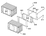
도 1 내지 도 4에는 프레임이 바람직하게는 플라스틱으로 이루어지며 패키기 막의 내부 면과 고온 프레스에 의해 결합되는, 본 발명의 바람직한 실시예가 도시된다. 이 실시예에서 프레임과 결합되는 패키지 막의 절반은 도 5에 도시되듯이 다른 절반 위에 있다. 1 to 4 show a preferred embodiment of the invention in which the frame is preferably made of plastic and is bonded by hot press with the inner face of the package membrane. In this embodiment, one half of the package film combined with the frame is on top of the other half as shown in FIG.
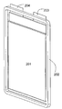
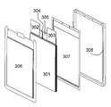
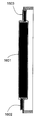
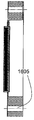
도 1에는 셀(103)의 패키지와 결합된 통합 프레임(102)을 포함하는 이 실시예에 따른 셀의 사시도가 도시된다. 패키지로부터 셀의 전도체(101)가 돌출한다. 도 2에는 동일한 셀의 다른 측면이 도시된다. 도면 번호들 201, 202 및 203은 셀의 전도체, 프레임 및 패키지를 나타낸다. 통합 프레임을 가진 셀의 분해도가 도 3에 도시된다. 셀 헤드의 2개의 전극 번들들(304, 305)과 전기 접속되고 전도체들(302, 303)이 장착되는 셀 스택(301)은 부분들(306 및 307)을 가지는 패키지 막에 의해 폐쇄되고, 상기 패키지 막은 프레임(308)에 의해 기계적으로 안정화된다. 다른 측면의 상응하는 분해도는 도 4에 도시된다. 여기에서도 전극 번들들(404, 405) 및 상기 전극 번들들에 장착된 전도체들(402, 403)을 가진 전극 스택(401)이 막 패키지의 2개의 부분들(406, 407)에 의해 둘러싸이고 프레임(408)에 의해 안정화된다.1 shows a perspective view of a cell according to this embodiment comprising an
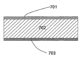
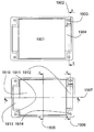
갈바닉 셀을 위한 전형적 패키지 막의 구성은 도 7에 도시된다. 알루미늄 막(702)은 하나의 측면이 폴리아미드(701)로, 그리고 다른 측면이 폴리프로필렌(703)으로 코팅된다. 다른 재료들, 층들 또는 코팅들을 가진 다른 막들도 당연히 가능하다.The configuration of a typical package film for a galvanic cell is shown in FIG. The
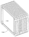
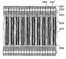
통합 프레임을 가진 본 발명에 따른 갈바닉 셀들로 이루어진 셀 블록의 바람직한 실시예가 도 8에 도시된다. 완성된 셀 블록(801)은 구성 중인 셀 블록(802)에, 도면 번호 803을 갖는, 프레임을 포함한 셀 같은 다른 셀들이 추가되도록 구성된다. 셀(803)은 프레임(807)과 압력 끼워 맞춤식으로 결합되는 전도체들(805, 806)을 포함한 원래 셀(804)로 이루어진다. 전체 셀 블록의 안정화를 위해 타이 로드(808, 809, 810 및 811)는 프레임 내의 상응하는 보어들을 통해 안내된다.A preferred embodiment of a cell block of galvanic cells according to the invention with an integrated frame is shown in FIG. 8. The completed
프레임들이 셀들의 센터링 또는 정렬을 용이하게 하는 노우즈 또는 홈들과 같은 구조를 포함하도록 구현되면, 보어들을 통한 타이 로드의 안내도 훨씬 더 용이해진다. 이 실시예에서 전도체들은 중량 절감식으로 프레임 둘레에 놓이거나 또는 그 둘레로 휘어있으므로 중실 콘택 스트립이 생략될 수 있다.If the frames are implemented to include structures such as noses or grooves that facilitate the centering or alignment of the cells, the guidance of the tie rods through the bores is much easier. In this embodiment, the conductors are placed around or bent around the frame in a weight-saving manner so that the solid contact strip can be omitted.
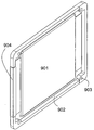
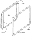
도 9에는 프레임 둘레에 놓이는 전도체들을 포함하는 셀이 상세하게 도시된다. 셀(901)은 프레임(902) 둘레에 놓인 전도체(904)를 포함한다. 프레임에는 타이 로드들의 관통 안내를 위한 홀(903)이 제공된다. 도 10에는 동일한 셀이 분해도로 도시된다. 도면에 도시된 것과 다르게, 전도체(1004)는 프레임(1002)의 장착 후에야 프레임 둘레로 휜다. 도 11에는 이 실시예의 갈바닉 셀들로 이루어진 셀 블록이 도시된다. 9 shows in detail a cell comprising conductors placed around the frame.
도 12에는 도 11에 도시된 셀 블록의 단면도가 도시된다. 셀(1201)의 셀 헤드(1202) 상에 전도체(1204)가 장착되고, 상기 전도체는 프레임(1205) 둘레로 휘고 인접한 셀의 전도체와 전기 접촉한다. 셀(1201)의 대향 배치된 전도체는 프레임(1205) 둘레로 휘지 않으므로 인접한 셀의 전도체(1206)로부터 전기 절연되고, 상기 전도체는 그 다음에 인접한 셀의 전도체와 다시 전기 접촉한다. 이로써, 셀 블록 구성시 전도체들의 적합한 전기 접속이 다른 보조 수단 없이 실제로 달성될 수 있다.12 is a cross-sectional view of the cell block shown in FIG. 11.
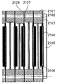
도 13에 도시된 본 발명의 실시예는 더 적은 공간을 필요로 한다. 셀(1301)의 전도체들(1304)은 용접을 위해 서로 평행하게 패키지로부터 돌출되고 압력 끼워 맞춤식으로 서로 접촉한다. 프레임(1302)은 타이 로드의 관통을 위한 보어(1303)를 포함한다. 이러한 실시예의 분해도는 도 14에 도시된다. 셀(1401)의 패키지는 에지들에 프레임(1402)과의 고온 프레스에 적합한 특수 면들(1405)을 포함한다. 셀의 전도체들(1404)은 적합한 접촉이 자동으로 이루어지도록 배치된다. 셀의 패키지 에지들은 상응하는 관통부들(1403)과 합동으로 프레임(1402) 내에 배치되는 타이 로드의 관통을 위한 홀들(1406)을 포함한다. 이 실시예의 분해도는 도 15에 도시된다. 전도체들(1502, 1503)을 포함한 전극 스택(1501)이 패키지의 상부(1506), 프레임(1508) 및 패키지의 하부(1507) 사이에서 둘러싸인다. 패키지의 상부 및 하부는 도 15에 도시되는 형태 엘리먼트들을 포함하고, 상기 형태 엘리먼트들은 전도체들의 적합한 자동 접촉을 지원한다. The embodiment of the present invention shown in FIG. 13 requires less space. The
도 16에는 도 19 하부에 도시된 갈바닉 셀의 3가지 상이한 단면도들 16a, 16b 및 16c가 도시된다. 여기에서, 도 16a는 라인(1907)을 따라 절개된 단면도를 도시하고, 도 16b는 라인(1906)을 따라 절개된 단면도를 도시하고, 도 16c는 라인(1905)에 따라 절개된 단면도를 도시한다. 도 16a는 셀 헤드들(1602 및 1603)을 포함한 셀 스택(1601)을 도시하고, 도 16b는 프레임(1604)을 통과하는 관통부(1605)를 도시하고, 도 16c는 도 16a에 대해 수직으로 이루어진 셀의 단면도를 도시한다. FIG. 16 shows three different cross-sectional views 16a, 16b and 16c of the galvanic cell shown at the bottom of FIG. 19. Here, FIG. 16A shows a cross-sectional view taken along
도 17에는 본 발명의 실시예의 프레임 영역의 확대 단면도가 도시된다. 셀(1701)의 패키지 막(1702, 1703)의 2부분들과 결합되는 프레임들(1704)이 도시된다. 도 18에는 본 발명의 실시예에 따른 셀들로 이루어진 셀 스택이 도시된다. 도 20에는 도 19의 상부에 도시되는 절개에 따른 셀 블록의 단면도가 도시된다. 도 19에는 도 20의 부분의 확대도가 도시되고, 여기에는 본 발명의 실시예에서 공간이 좀 더 효율적으로 사용되는 것이 도 20에서보다 더 잘 도시된다. 도 21의 상부에 잘 도시된, 인접한 셀의 전도체(2108)와 전기 접촉하는 전도체(2107)의 특수한 형태 디자인에 의해, 셀 블록의 거의 갭 없는 구성이 얻어진다. 셀 스택(2104), 패키지(2105)의 하부면, 패키지(2106)의 상부면, 관통부(2102)를 포함하는 프레임(2101) 또는 프레임(2103)이 도시된다.17 is an enlarged cross-sectional view of the frame region of the embodiment of the present invention.
101, 201: 전도체
102, 202: 프레임
103, 203: 셀
801: 셀 블록
901: 셀
902, 1002: 프레임
904, 1004: 전도체101, 201: conductor
102, 202: frame
103, 203 cells
801: cell block
901: cell
902, 1002: frame
904, 1004: conductor
Claims (12)
상기 프레임은 상기 셀의 제조시 상기 셀의 상기 패키지와 견고하게 결합될 수 있도록 형성되는 것을 특징으로 하는 프레임.A frame for a galvanic cell comprising a package in the form of a membrane, wherein the two or more conductors protrude from the package, substantially consisting of an electrode stack.
And the frame is formed so as to be firmly coupled with the package of the cell during manufacture of the cell.
상기 패키지의 폐쇄시 프레임이 상기 패키지와 견고하게 결합되는 것을 특징으로 하는 갈바닉 셀의 제조 방법.A method of manufacturing a galvanic cell in which an electrode stack is enclosed in a film-shaped package and two or more conductors protrude from the package.
The method of manufacturing a galvanic cell, characterized in that the frame is firmly coupled to the package when the package is closed.
Applications Claiming Priority (2)
| Application Number | Priority Date | Filing Date | Title |
|---|---|---|---|
| DE102009010794A DE102009010794A1 (en) | 2009-02-27 | 2009-02-27 | Galvanic cell with frame and method for its production |
| DE102009010794.0 | 2009-02-27 |
Publications (1)
| Publication Number | Publication Date |
|---|---|
| KR20120006984A true KR20120006984A (en) | 2012-01-19 |
Family
ID=42167305
Family Applications (1)
| Application Number | Title | Priority Date | Filing Date |
|---|---|---|---|
| KR1020117022491A KR20120006984A (en) | 2009-02-27 | 2010-03-01 | Galvanic cell having a frame and method for the production of said galvanic cell |
Country Status (8)
| Country | Link |
|---|---|
| US (1) | US20120135288A1 (en) |
| EP (1) | EP2401779A1 (en) |
| JP (1) | JP2012519349A (en) |
| KR (1) | KR20120006984A (en) |
| CN (1) | CN102334211A (en) |
| BR (1) | BRPI1007834A2 (en) |
| DE (1) | DE102009010794A1 (en) |
| WO (1) | WO2010097242A1 (en) |
Families Citing this family (16)
| Publication number | Priority date | Publication date | Assignee | Title |
|---|---|---|---|---|
| DE102010034545A1 (en) | 2010-08-17 | 2012-02-23 | Li-Tec Battery Gmbh | Electrochemical cell with at least one pressure relief device |
| DE102010055610A1 (en) * | 2010-12-22 | 2012-06-28 | Daimler Ag | Battery with a stack of several prismatic battery cells |
| US8980465B2 (en) * | 2011-01-05 | 2015-03-17 | Samsung Sdi Co., Ltd. | Battery pack |
| JP2014032789A (en) * | 2012-08-02 | 2014-02-20 | Nissan Motor Co Ltd | Thin battery |
| JP2014063598A (en) * | 2012-09-03 | 2014-04-10 | Nec Energy Devices Ltd | Battery pack |
| KR101934396B1 (en) * | 2012-10-30 | 2019-01-02 | 삼성에스디아이 주식회사 | Battery assembly |
| US9711770B2 (en) | 2012-11-27 | 2017-07-18 | Apple Inc. | Laminar battery system |
| US10141600B2 (en) | 2013-03-15 | 2018-11-27 | Apple Inc. | Thin film pattern layer battery systems |
| CN105186040A (en) * | 2014-06-23 | 2015-12-23 | 台达电子工业股份有限公司 | Battery making method |
| US10930915B2 (en) | 2014-09-02 | 2021-02-23 | Apple Inc. | Coupling tolerance accommodating contacts or leads for batteries |
| US20160093837A1 (en) * | 2014-09-30 | 2016-03-31 | Apple Inc. | Efficient Battery Pouch |
| US9755198B2 (en) * | 2015-10-07 | 2017-09-05 | Lg Chem, Ltd. | Battery cell assembly |
| CN105591060B (en) * | 2016-02-25 | 2019-09-03 | 宁德时代新能源科技股份有限公司 | Power battery pack device |
| KR20200070944A (en) * | 2018-12-10 | 2020-06-18 | 현대자동차주식회사 | Elastomer cell frame for fuel cell and manufacturing method thereof and unit cell comprising thereof |
| DE102018221539A1 (en) * | 2018-12-12 | 2020-06-18 | Robert Bosch Gmbh | Battery module unit comprising at least two battery cells |
| US11824220B2 (en) | 2020-09-03 | 2023-11-21 | Apple Inc. | Electronic device having a vented battery barrier |
Family Cites Families (13)
| Publication number | Priority date | Publication date | Assignee | Title |
|---|---|---|---|---|
| CA1068780A (en) * | 1977-05-31 | 1979-12-25 | Thomas J. Dougherty | Storage battery with folded plates and separators |
| US5487958A (en) * | 1993-12-06 | 1996-01-30 | Tura; Drew | Interlocking frame system for lithium-polymer battery construction |
| EP0814529A1 (en) * | 1996-06-19 | 1997-12-29 | Koninklijke Philips Electronics N.V. | Thin card containing flat accumulator and connecting devices |
| US20040067416A1 (en) * | 2002-10-07 | 2004-04-08 | Maclean Gregory K. | Protective frame for rechargeable battery cells |
| JP4570888B2 (en) * | 2004-03-18 | 2010-10-27 | 富士重工業株式会社 | Power storage device |
| JP2006019075A (en) * | 2004-06-30 | 2006-01-19 | Nissan Motor Co Ltd | Flat type battery and battery pack using its battery |
| JP4457812B2 (en) * | 2004-08-30 | 2010-04-28 | 新神戸電機株式会社 | Battery pack and module battery |
| JP4457931B2 (en) * | 2005-03-17 | 2010-04-28 | トヨタ自動車株式会社 | Battery module |
| KR101042132B1 (en) * | 2005-03-23 | 2011-06-16 | 에스케이이노베이션 주식회사 | Case for high power rechargeable lithium battery |
| KR100880386B1 (en) * | 2005-06-03 | 2009-01-23 | 주식회사 엘지화학 | Secondary Battery of Novel Structure and Battery Pack Having the Same |
| JP4909895B2 (en) * | 2005-06-17 | 2012-04-04 | 日本電気株式会社 | Electrical device assembly and film-covered electrical device structure |
| JP4829587B2 (en) * | 2005-10-14 | 2011-12-07 | 日本電気株式会社 | Electrical device assembly and manufacturing method thereof |
| JP5398273B2 (en) * | 2009-01-09 | 2014-01-29 | Fdk株式会社 | Power storage module |
-
2009
- 2009-02-27 DE DE102009010794A patent/DE102009010794A1/en not_active Withdrawn
-
2010
- 2010-03-01 CN CN201080009624XA patent/CN102334211A/en active Pending
- 2010-03-01 WO PCT/EP2010/001260 patent/WO2010097242A1/en active Application Filing
- 2010-03-01 BR BRPI1007834A patent/BRPI1007834A2/en not_active IP Right Cessation
- 2010-03-01 EP EP10707466A patent/EP2401779A1/en not_active Withdrawn
- 2010-03-01 JP JP2011551446A patent/JP2012519349A/en active Pending
- 2010-03-01 KR KR1020117022491A patent/KR20120006984A/en not_active Application Discontinuation
- 2010-03-01 US US13/203,252 patent/US20120135288A1/en not_active Abandoned
Also Published As
| Publication number | Publication date |
|---|---|
| WO2010097242A1 (en) | 2010-09-02 |
| BRPI1007834A2 (en) | 2016-02-23 |
| DE102009010794A1 (en) | 2010-09-02 |
| JP2012519349A (en) | 2012-08-23 |
| EP2401779A1 (en) | 2012-01-04 |
| CN102334211A (en) | 2012-01-25 |
| US20120135288A1 (en) | 2012-05-31 |
Similar Documents
| Publication | Publication Date | Title |
|---|---|---|
| KR20120006984A (en) | Galvanic cell having a frame and method for the production of said galvanic cell | |
| US10622597B2 (en) | Battery cell having outer edge sealed portion with sealed lines and battery cell sealing apparatus for manufacture thereof | |
| US20120214055A1 (en) | Galvanic cell comprising a frame, and method for the production thereof | |
| US10547034B2 (en) | Sealing apparatus of pouch-type secondary battery | |
| JP4728758B2 (en) | Electric device module manufacturing method and electric device module | |
| US20120082888A1 (en) | Electrochemical device and process of manufacturing same | |
| EP3070779B1 (en) | Method for manufacturing film-packaged cell | |
| US20140356689A1 (en) | Battery module and battery unit | |
| JP2013145756A (en) | Thin battery and battery pack | |
| JP7088410B2 (en) | Power storage module | |
| JP5605831B2 (en) | Electronic component, electronic device, and method of manufacturing electronic component | |
| US20160028071A1 (en) | Light-Weight Bipolar Valve Regulated Lead Acid Batteries and Method | |
| JP2010165686A (en) | Energy storing module and frame for the same | |
| CN102918615A (en) | Electrochemical device | |
| JP6862639B2 (en) | Heat block | |
| JP2006164922A (en) | Power storage device and member used for manufacture of the same | |
| JP4666131B2 (en) | LAMINATE FILM HEAT FUSION METHOD, FILM PACKAGE BATTERY MANUFACTURING METHOD, AND LAMINATE FILM HEAT FUSION DEVICE | |
| KR101546002B1 (en) | electrochemical energy storage device | |
| US20220416377A1 (en) | Manufacturing method of pouch battery | |
| JP4019229B2 (en) | Battery manufacturing method | |
| JP2017154760A (en) | Seal bar, seal bar system, and method of manufacturing bag-like article | |
| JP2021044079A (en) | Power storage module, and manufacturing method of power storage module | |
| JP2003123731A (en) | Rectangular sealed battery | |
| JP2006128009A (en) | Power storage module and this frame for modules | |
| JP2017228381A (en) | Battery and manufacturing method of battery |
Legal Events
| Date | Code | Title | Description |
|---|---|---|---|
| WITN | Application deemed withdrawn, e.g. because no request for examination was filed or no examination fee was paid |