JP2012519349A - Galvanic battery having a frame and manufacturing method thereof - Google Patents
Galvanic battery having a frame and manufacturing method thereof Download PDFInfo
- Publication number
- JP2012519349A JP2012519349A JP2011551446A JP2011551446A JP2012519349A JP 2012519349 A JP2012519349 A JP 2012519349A JP 2011551446 A JP2011551446 A JP 2011551446A JP 2011551446 A JP2011551446 A JP 2011551446A JP 2012519349 A JP2012519349 A JP 2012519349A
- Authority
- JP
- Japan
- Prior art keywords
- battery
- frame
- packaging material
- foil
- galvanic
- Prior art date
- Legal status (The legal status is an assumption and is not a legal conclusion. Google has not performed a legal analysis and makes no representation as to the accuracy of the status listed.)
- Pending
Links
Images


Classifications
-
- H—ELECTRICITY
- H01—ELECTRIC ELEMENTS
- H01M—PROCESSES OR MEANS, e.g. BATTERIES, FOR THE DIRECT CONVERSION OF CHEMICAL ENERGY INTO ELECTRICAL ENERGY
- H01M10/00—Secondary cells; Manufacture thereof
- H01M10/04—Construction or manufacture in general
- H01M10/0413—Large-sized flat cells or batteries for motive or stationary systems with plate-like electrodes
-
- H—ELECTRICITY
- H01—ELECTRIC ELEMENTS
- H01M—PROCESSES OR MEANS, e.g. BATTERIES, FOR THE DIRECT CONVERSION OF CHEMICAL ENERGY INTO ELECTRICAL ENERGY
- H01M50/00—Constructional details or processes of manufacture of the non-active parts of electrochemical cells other than fuel cells, e.g. hybrid cells
- H01M50/10—Primary casings, jackets or wrappings of a single cell or a single battery
- H01M50/102—Primary casings, jackets or wrappings of a single cell or a single battery characterised by their shape or physical structure
- H01M50/105—Pouches or flexible bags
-
- H—ELECTRICITY
- H01—ELECTRIC ELEMENTS
- H01M—PROCESSES OR MEANS, e.g. BATTERIES, FOR THE DIRECT CONVERSION OF CHEMICAL ENERGY INTO ELECTRICAL ENERGY
- H01M50/00—Constructional details or processes of manufacture of the non-active parts of electrochemical cells other than fuel cells, e.g. hybrid cells
- H01M50/10—Primary casings, jackets or wrappings of a single cell or a single battery
- H01M50/116—Primary casings, jackets or wrappings of a single cell or a single battery characterised by the material
- H01M50/117—Inorganic material
- H01M50/119—Metals
-
- H—ELECTRICITY
- H01—ELECTRIC ELEMENTS
- H01M—PROCESSES OR MEANS, e.g. BATTERIES, FOR THE DIRECT CONVERSION OF CHEMICAL ENERGY INTO ELECTRICAL ENERGY
- H01M50/00—Constructional details or processes of manufacture of the non-active parts of electrochemical cells other than fuel cells, e.g. hybrid cells
- H01M50/10—Primary casings, jackets or wrappings of a single cell or a single battery
- H01M50/116—Primary casings, jackets or wrappings of a single cell or a single battery characterised by the material
- H01M50/121—Organic material
-
- H—ELECTRICITY
- H01—ELECTRIC ELEMENTS
- H01M—PROCESSES OR MEANS, e.g. BATTERIES, FOR THE DIRECT CONVERSION OF CHEMICAL ENERGY INTO ELECTRICAL ENERGY
- H01M50/00—Constructional details or processes of manufacture of the non-active parts of electrochemical cells other than fuel cells, e.g. hybrid cells
- H01M50/10—Primary casings, jackets or wrappings of a single cell or a single battery
- H01M50/116—Primary casings, jackets or wrappings of a single cell or a single battery characterised by the material
- H01M50/124—Primary casings, jackets or wrappings of a single cell or a single battery characterised by the material having a layered structure
- H01M50/126—Primary casings, jackets or wrappings of a single cell or a single battery characterised by the material having a layered structure comprising three or more layers
-
- H—ELECTRICITY
- H01—ELECTRIC ELEMENTS
- H01M—PROCESSES OR MEANS, e.g. BATTERIES, FOR THE DIRECT CONVERSION OF CHEMICAL ENERGY INTO ELECTRICAL ENERGY
- H01M50/00—Constructional details or processes of manufacture of the non-active parts of electrochemical cells other than fuel cells, e.g. hybrid cells
- H01M50/10—Primary casings, jackets or wrappings of a single cell or a single battery
- H01M50/172—Arrangements of electric connectors penetrating the casing
- H01M50/174—Arrangements of electric connectors penetrating the casing adapted for the shape of the cells
- H01M50/178—Arrangements of electric connectors penetrating the casing adapted for the shape of the cells for pouch or flexible bag cells
-
- H—ELECTRICITY
- H01—ELECTRIC ELEMENTS
- H01M—PROCESSES OR MEANS, e.g. BATTERIES, FOR THE DIRECT CONVERSION OF CHEMICAL ENERGY INTO ELECTRICAL ENERGY
- H01M50/00—Constructional details or processes of manufacture of the non-active parts of electrochemical cells other than fuel cells, e.g. hybrid cells
- H01M50/20—Mountings; Secondary casings or frames; Racks, modules or packs; Suspension devices; Shock absorbers; Transport or carrying devices; Holders
- H01M50/204—Racks, modules or packs for multiple batteries or multiple cells
- H01M50/207—Racks, modules or packs for multiple batteries or multiple cells characterised by their shape
- H01M50/211—Racks, modules or packs for multiple batteries or multiple cells characterised by their shape adapted for pouch cells
-
- H—ELECTRICITY
- H01—ELECTRIC ELEMENTS
- H01M—PROCESSES OR MEANS, e.g. BATTERIES, FOR THE DIRECT CONVERSION OF CHEMICAL ENERGY INTO ELECTRICAL ENERGY
- H01M50/00—Constructional details or processes of manufacture of the non-active parts of electrochemical cells other than fuel cells, e.g. hybrid cells
- H01M50/20—Mountings; Secondary casings or frames; Racks, modules or packs; Suspension devices; Shock absorbers; Transport or carrying devices; Holders
- H01M50/258—Modular batteries; Casings provided with means for assembling
-
- H—ELECTRICITY
- H01—ELECTRIC ELEMENTS
- H01M—PROCESSES OR MEANS, e.g. BATTERIES, FOR THE DIRECT CONVERSION OF CHEMICAL ENERGY INTO ELECTRICAL ENERGY
- H01M50/00—Constructional details or processes of manufacture of the non-active parts of electrochemical cells other than fuel cells, e.g. hybrid cells
- H01M50/50—Current conducting connections for cells or batteries
- H01M50/543—Terminals
- H01M50/547—Terminals characterised by the disposition of the terminals on the cells
- H01M50/55—Terminals characterised by the disposition of the terminals on the cells on the same side of the cell
-
- H—ELECTRICITY
- H01—ELECTRIC ELEMENTS
- H01M—PROCESSES OR MEANS, e.g. BATTERIES, FOR THE DIRECT CONVERSION OF CHEMICAL ENERGY INTO ELECTRICAL ENERGY
- H01M50/00—Constructional details or processes of manufacture of the non-active parts of electrochemical cells other than fuel cells, e.g. hybrid cells
- H01M50/50—Current conducting connections for cells or batteries
- H01M50/543—Terminals
- H01M50/552—Terminals characterised by their shape
- H01M50/553—Terminals adapted for prismatic, pouch or rectangular cells
- H01M50/557—Plate-shaped terminals
-
- Y—GENERAL TAGGING OF NEW TECHNOLOGICAL DEVELOPMENTS; GENERAL TAGGING OF CROSS-SECTIONAL TECHNOLOGIES SPANNING OVER SEVERAL SECTIONS OF THE IPC; TECHNICAL SUBJECTS COVERED BY FORMER USPC CROSS-REFERENCE ART COLLECTIONS [XRACs] AND DIGESTS
- Y02—TECHNOLOGIES OR APPLICATIONS FOR MITIGATION OR ADAPTATION AGAINST CLIMATE CHANGE
- Y02E—REDUCTION OF GREENHOUSE GAS [GHG] EMISSIONS, RELATED TO ENERGY GENERATION, TRANSMISSION OR DISTRIBUTION
- Y02E60/00—Enabling technologies; Technologies with a potential or indirect contribution to GHG emissions mitigation
- Y02E60/10—Energy storage using batteries
-
- Y—GENERAL TAGGING OF NEW TECHNOLOGICAL DEVELOPMENTS; GENERAL TAGGING OF CROSS-SECTIONAL TECHNOLOGIES SPANNING OVER SEVERAL SECTIONS OF THE IPC; TECHNICAL SUBJECTS COVERED BY FORMER USPC CROSS-REFERENCE ART COLLECTIONS [XRACs] AND DIGESTS
- Y02—TECHNOLOGIES OR APPLICATIONS FOR MITIGATION OR ADAPTATION AGAINST CLIMATE CHANGE
- Y02P—CLIMATE CHANGE MITIGATION TECHNOLOGIES IN THE PRODUCTION OR PROCESSING OF GOODS
- Y02P70/00—Climate change mitigation technologies in the production process for final industrial or consumer products
- Y02P70/50—Manufacturing or production processes characterised by the final manufactured product
-
- Y—GENERAL TAGGING OF NEW TECHNOLOGICAL DEVELOPMENTS; GENERAL TAGGING OF CROSS-SECTIONAL TECHNOLOGIES SPANNING OVER SEVERAL SECTIONS OF THE IPC; TECHNICAL SUBJECTS COVERED BY FORMER USPC CROSS-REFERENCE ART COLLECTIONS [XRACs] AND DIGESTS
- Y10—TECHNICAL SUBJECTS COVERED BY FORMER USPC
- Y10T—TECHNICAL SUBJECTS COVERED BY FORMER US CLASSIFICATION
- Y10T29/00—Metal working
- Y10T29/49—Method of mechanical manufacture
- Y10T29/49002—Electrical device making
- Y10T29/49108—Electric battery cell making
Landscapes
- Chemical & Material Sciences (AREA)
- Chemical Kinetics & Catalysis (AREA)
- Electrochemistry (AREA)
- General Chemical & Material Sciences (AREA)
- Engineering & Computer Science (AREA)
- Manufacturing & Machinery (AREA)
- Inorganic Chemistry (AREA)
- Battery Mounting, Suspending (AREA)
- Sealing Battery Cases Or Jackets (AREA)
- Connection Of Batteries Or Terminals (AREA)
- Primary Cells (AREA)
Abstract
箔状の包装材を備える電極積層体から構成され、包装材から少なくとも2つの導体が延出している、ガルバニ電池用のフレームが、電池の製造時に電池の包装材と固着できるように構成されている。このようなガルバニ電池の製造において、包装材を密閉するときにフレームが包装材と固着される。 A frame for a galvanic battery, which is composed of an electrode laminate including a foil-shaped packaging material and has at least two conductors extending from the packaging material, is configured to be able to be fixed to the packaging material of the battery at the time of manufacturing the battery. Yes. In manufacturing such a galvanic cell, the frame is fixed to the packaging material when the packaging material is sealed.
Description
本発明は、フレームを備えるガルバニ電池およびその製造方法に関する。電気化学的に有効な内容物が箔状の包装材、例えば両面にプラスチックコーティングを施された薄いアルミニウム箔によって取り囲まれ、この包装材を貫通して薄板形状の電気接続線(いわゆる「導体」)が延在している、平型で長方形に形成された電池(バッテリ電池や蓄電器など)が知られている。他の電池構造形態とは異なり、導体が絶縁状態で包装材を貫通して延在しているので、そのような電池の包装材は電圧を導かない。そのように構成されたバッテリ電池は、パウチ型電池またはコーヒーバック型電池とも呼ばれる。 The present invention relates to a galvanic battery including a frame and a manufacturing method thereof. The electrochemically effective contents are surrounded by a foil-like packaging material, for example a thin aluminum foil with a plastic coating on both sides, and through this packaging material a thin plate-shaped electrical connection line (so-called `` conductor '') A battery (battery battery, capacitor, etc.) that is flat and rectangular is known. Unlike other battery structure configurations, such battery packaging does not conduct voltage because the conductor extends in an insulated manner through the packaging. The battery battery configured as such is also called a pouch-type battery or a coffee bag-type battery.
例えば電気自動車やハイブリッド自動車における様々な用途において、多くの場合、個々のガルバニ電池が直列および/または並列に接続され、付属の電子機器と共に筐体内にある。箔で包装されたパウチ型電池は、多くの場合、機械的耐性が非常に高いわけではないので、バッテリ筐体に直接組み込むことはできないことが多く、まず適切な支持構造によって機械的に安定させなければならない。 In various applications, for example, in electric vehicles and hybrid vehicles, individual galvanic cells are often connected in series and / or in parallel and are in a housing with attached electronics. Pouch-type batteries wrapped in foil are often not very mechanically resistant and cannot often be integrated directly into the battery housing, and are first mechanically stabilized by a suitable support structure. There must be.
本発明の課題は、ガルバニ電池の使用および取扱いを容易にすること、およびその包装箔の脆弱性に伴う問題を緩和する、またはできるだけ解決することである。この課題は、独立請求項のいずれか一項に記載の製造物(Erzeugnis)または方法によって解決される。 The object of the present invention is to facilitate the use and handling of galvanic cells and to mitigate or solve as much as possible the problems associated with the fragility of the packaging foil. This problem is solved by a product (Erzeugnis) or method according to any one of the independent claims.
本発明によれば、ガルバニ電池用のフレームが提供される。ここで、電池は、実質的に電極積層体(Elektrodenstapel)と箔状の包装材とから構成され、包装材から少なくとも2つの導体が延出している。フレームは、電池の製造時に電池の包装材と固着(fest verbinden)できるように構成されている。本発明によるガルバニ電池の製造方法では、包装材を密閉するときにフレームが包装材と固着される。 According to the present invention, a frame for a galvanic battery is provided. Here, the battery is substantially composed of an electrode laminate (Elektrodenstapel) and a foil-like packaging material, and at least two conductors extend from the packaging material. The frame is configured to be fest verbinden with the battery packaging during battery manufacture. In the method for manufacturing a galvanic cell according to the present invention, the frame is fixed to the packaging material when the packaging material is sealed.
以下、本発明のさらなる説明で使用するいくつかの概念を説明する。 In the following, some concepts used in the further description of the invention will be explained.
概念「電極積層体」は、任意の構造のガルバニ電池の電気化学的に有効な内容物を表すものとして使用する。それに対し、電池の「包装材」は、電極積層体を環境から隔離する、電気化学反応に関与しない材料を意味する。 The concept “electrode stack” is used to represent the electrochemically effective contents of a galvanic cell of any structure. In contrast, the “packaging material” of a battery means a material that isolates the electrode laminate from the environment and does not participate in an electrochemical reaction.
これに関連して「箔状の包装材」というとき、それは、好ましくは少ない材料使用量で電極積層体を周囲から有効に遮蔽し隔離するという目的を満たす、あらゆる種類の包装材または外被(Einschluessen)を意味するものとする。隔離は、ここでは、物質および電流の移動を妨げるように作用するものとする。ただしまた、この概念「箔状の包装材」は、通常の意味での箔のみを含むのではなく、特にプラスチックコーティングを施された金属箔も含む。 In this context, “foil-like packaging material” refers to any type of packaging material or jacket (that preferably fulfills the purpose of effectively shielding and isolating the electrode stack from the surroundings with low material usage). Einschluessen). Isolation shall here act to prevent the movement of material and current. However, this concept “foil-shaped packaging material” does not include only foils in the usual sense, but also includes metal foils with a plastic coating in particular.
「導体」とは、本発明の意味では、電池へまたは電池から電荷を移動できるように包装材を貫通して外に延在する電気導体を意味する。 “Conductor” means, in the sense of the present invention, an electrical conductor that extends out through the packaging so that charge can be transferred to or from the battery.
本発明の意味での「フレーム」は、環境からの影響に対して電池を機械的に安定させるのに適し、電池の製造時に電池の包装材と固着できるあらゆる構造的機構を意味するものとする。用語の選択が既に示唆するように、フレームは、好ましくは実質的に枠形の機構であり、実質的にガルバニ電池に機械的安定性を与えることがその役割である。本発明の有利な変形形態は従属請求項から明らかである。 “Frame” in the sense of the present invention is intended to mean any structural mechanism that is suitable for mechanically stabilizing the battery against environmental influences and that can be secured to the packaging material of the battery during the manufacture of the battery. . As the term selection already suggests, the frame is preferably a substantially frame-shaped mechanism, whose role is to provide mechanical stability to the galvanic cell substantially. Advantageous variants of the invention are evident from the dependent claims.
以下、本発明を、好ましい例示的実施形態に基づいて図面を用いて、より詳細に説明する。 Hereinafter, the present invention will be described in more detail with reference to the drawings based on preferred exemplary embodiments.
本発明は、箔状の包装材を備える電極積層体から実質的に構成され、包装材から少なくとも2つの導体が延出している、ガルバニ電池を基礎とする。本発明によれば、そのようなガルバニ電池を、電池の製造時に電池の包装材と固着できるように構成されたフレームによって安定させる。本発明のいくつかの実施形態の対応する形態では、バッテリへの取付け時になって初めて、そのときに行うべきフレームまたは枠との結合によってガルバニ電池が安定にされるのではなく、電池ブロックへの取付け前に、本発明によるフレームによって電池が既に安定しているという利点がある。したがって包装材を密閉するとき既にフレームが電池と結合されている本発明に係る方法は、電池が既に他の製造工程において、すなわち電池の充填時、成形時、計画的エージング時、またはいわゆる「グレーディング(grading)」時に機械的な影響から既に保護されているという利点をさらに有する。 The present invention is based on a galvanic cell which is substantially composed of an electrode laminate comprising a foil-like packaging material, and at least two conductors extend from the packaging material. According to the present invention, such a galvanic cell is stabilized by a frame configured to be able to be fixed to the battery packaging material during the manufacture of the battery. In a corresponding form of some embodiments of the present invention, the galvanic battery is not stabilized only by attachment to the frame or frame to be performed at that time, but only when it is attached to the battery. The advantage is that the battery is already stable by the frame according to the invention before installation. Thus, the method according to the invention, in which the frame is already joined to the battery when sealing the packaging material, the battery is already in another manufacturing process, i.e. when the battery is filled, molded, planned aging or so-called "grading". It has the further advantage that it is already protected from mechanical influences when “grading”.
本発明による電池とフレームとの結合を確立するために、用途に応じて、特に例えば接着などの材料結合法(stoffschluessige Verfahren)または同様の方法が適している。好ましくは、フレームは熱圧着または熱封止(Heisssiegelung)によって包装箔と結合させることもでき、これは、好ましくは、両方の接合部位(Fuegepartner)間にある熱可塑性層を部分的に溶融し、続いて圧力をかけながら冷却することによって行われる。包装箔は、いずれにせよ、そのような結合に適した対応するコーティングを施されていることが多い。 In order to establish a bond between the battery and the frame according to the invention, depending on the application, in particular a material bonding method such as gluing (stoffschluessige Verfahren) or a similar method is suitable. Preferably, the frame can also be bonded to the packaging foil by thermocompression or heat sealing (Heisssiegelung), which preferably partially melts the thermoplastic layer between both joint parts (Fuegepartner), Subsequently, cooling is performed while applying pressure. In any case, the packaging foil is often provided with a corresponding coating suitable for such bonding.
概念「熱封止」は、好ましくは熱圧着によって包装材料(例えば複合箔)の熱可塑性溶融層を結合させる方法を意味する。包装技術において、熱封止は、箔を溶接するための1つの重要な方法である。実質的に以下の2つのタイプに分けられる。
a)封止ジョー間で加熱ロッドまたは加熱棒を用いる封止(接触封止とも呼ばれる)
b)インパルス式封止
The concept “heat sealing” means a method of bonding thermoplastic melt layers of packaging material (eg composite foil), preferably by thermocompression bonding. In packaging technology, heat sealing is one important method for welding foils. It can be divided into the following two types.
a) Sealing using a heating rod or heating rod between sealing jaws (also called contact sealing)
b) Impulse sealing
第1のタイプにおいては、好ましくは可動の封止ジョーが、加熱されたロッドを支持する。好ましくは固定した下側封止ジョーは、封止継ぎ目の凹凸をならすために、弾性材料から構成される表面を備えていることが多い。この種の封止要素は、袋の製造および密閉用の多くの市販の機械、ならびに成形機、充填機、および密閉機で使用される。 In the first type, preferably a movable sealing jaw supports the heated rod. Preferably, the fixed lower sealing jaws are often provided with a surface made of an elastic material in order to smooth out the sealing seams. This type of sealing element is used in many commercial machines for bag making and sealing, as well as molding machines, filling machines and sealing machines.
封止継ぎ目が非常に長い場合には、封止面全体にわたって一様な圧力を保証するために、加熱ロッドを非常に正確な寸法で、いかなる誤差もないように加工しなければならないことが多い。整然とした封止継ぎ目を実現するために、多くの場合、封止ツールに入れる前に延伸装置によって箔を平坦にする。別の方法として、鋸状の封止面を有する加熱ロッドを使用することができるが、これは箔に穴を開ける危険がある。 If the sealing seam is very long, the heating rod often has to be machined with very accurate dimensions and without any error in order to ensure a uniform pressure across the sealing surface. . In order to achieve an orderly sealing seam, the foil is often flattened by a stretching device prior to entering the sealing tool. As an alternative, a heating rod with a serrated sealing surface can be used, but this has the risk of perforating the foil.
固定した低温の封止ジョーの弾性表面にはシリコーンゴムが適していることが分かっている。この背圧棒材は、わずかに反った形状にされることがよくある。封止プロセスにおいて、まず封止継ぎ目の中央で圧力が生成され、ツールを閉じるときにこの圧力が縁部に向かって広がる。それにより最適な封止継ぎ目が生成されることになる。さらに、小さな液滴があれば封止領域から押し出されるはずである。そのような液滴があれば、水蒸気の発生によって封止継ぎ目が破壊されてしまう。 It has been found that silicone rubber is suitable for the elastic surface of the fixed cold sealing jaw. This back pressure bar is often slightly warped. In the sealing process, a pressure is first generated in the middle of the sealing seam and this pressure spreads towards the edge when the tool is closed. This produces an optimal sealing seam. Furthermore, any small droplets should be pushed out of the sealed area. If there are such droplets, the sealing seam will be destroyed by the generation of water vapor.
インパルス式封止では、封止棒材の温度は短時間しか維持されず、封止サイクル全体にわたっては維持されない。必要な熱は、両方の封止ジョーにある2つの小さな抵抗素子によって発生させられる。 In impulse sealing, the temperature of the sealing bar is only maintained for a short time and not throughout the sealing cycle. The necessary heat is generated by two small resistive elements on both sealing jaws.
封止すべき箔を挟んで封止ツールが閉じるとすぐに、短い電流インパルスによって溶接が行われる。加熱ロッドによる封止に比べ、熱が作用する時間が短く、余剰の熱はすぐに排除される。耐熱性材料から構成される薄い絶縁箔でツールの封止面を更に覆って、封止された材料がくっつかないようにすることができる。 As soon as the sealing tool closes with the foil to be sealed, welding is performed with a short current impulse. Compared to sealing with a heating rod, the time during which the heat acts is short, and excess heat is immediately eliminated. The sealing surface of the tool can be further covered with a thin insulating foil composed of a refractory material so that the sealed material does not stick.
包装箔をフレームに大面積で結合させることにより、構造に負荷がかかったときに通常なら発生しやすい機械的応力ピークをほぼ防ぐことができる。フレームへの結合は包装箔の内面で行うことができ、この内面はポリプロピレンでコーティングされていることが多い。図5は、フレームと包装箔の内面とのそのような結合を示す。 By bonding the wrapping foil to the frame in a large area, it is possible to substantially prevent mechanical stress peaks that would normally occur when the structure is loaded. Bonding to the frame can be done on the inner surface of the packaging foil, which is often coated with polypropylene. FIG. 5 shows such a connection between the frame and the inner surface of the packaging foil.
本発明の別の実施形態によれば、フレームを包装材の外面と結合することもでき、この外面はポリアミドでコーティングされていることが多い。本発明のそのような実施形態は図6に示されている。 According to another embodiment of the present invention, the frame can also be bonded to the outer surface of the wrapping material, which is often coated with polyamide. Such an embodiment of the present invention is shown in FIG.
さらに、電池の密閉、すなわち包装箔の両部分の結合と、フレームとの結合とを1つの作業ステップで行うことが有利である。 Furthermore, it is advantageous to carry out the sealing of the battery, i.e. the joining of both parts of the packaging foil and the joining with the frame in one working step.
本発明に係るガルバニ電池から構成される電池ブロックの組立てを容易にするために、フレームに、対応する形状要素(Formelement)、例えば突起部または陥凹部を設けることが有利であり、したがってそれが好ましい。これらは、対応する形状要素同士が適切に嵌合することができるように例えばフレームの両面に設けられ、したがって電池の所期の位置合わせを容易にすることによって電池ブロックの組付けを助ける。 In order to facilitate the assembly of a battery block comprising a galvanic cell according to the invention, it is advantageous to provide the frame with a corresponding form element, for example a protrusion or a recess, which is therefore preferred . These are provided, for example, on both sides of the frame so that the corresponding shape elements can be properly fitted, thus assisting the assembly of the battery block by facilitating the intended alignment of the battery.
本発明によるフレームには、適切な箇所に孔または他の開口を設けることが好ましく、そこを通して通しボルト(Zuganker)を挿入することができ、これらの通しボルトが電池ブロックを一体に保持する。 The frame according to the invention is preferably provided with holes or other openings at appropriate locations, through which through bolts can be inserted, these through bolts holding the battery block together.
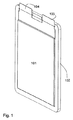
図1〜図4は、本発明の好ましい例示的実施形態を示し、ここで、フレームは好ましくはプラスチックから形成され、熱圧着によって包装箔の内面と結合されている。この例示的実施形態では、図5に示すように、フレームと結合された包装箔の半分が他方の半分を取り囲んで覆う。 1-4 show a preferred exemplary embodiment of the present invention, wherein the frame is preferably formed from plastic and bonded to the inner surface of the packaging foil by thermocompression bonding. In this exemplary embodiment, as shown in FIG. 5, half of the packaging foil combined with the frame surrounds and covers the other half.
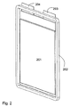
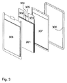
図1は、電池の包装材101と結合された一体型フレーム102を備えるこの例示的実施形態による電池の斜視図である。包装材から電池の導体103、104が突出している。図2は、同じ電池を反対側から示す。対応して、参照符号201、参照符号202、および参照符号203;204は、電池の包装材、フレーム、および導体を表す。図3は、一体型フレームを備えるこの電池の分解図を示す。2つの電極束304、305を有する電池頭部と導電接続され、かつ導体302、303が取り付けられている電池積層体301が、部分306および部分307を備える包装箔によって両側から密閉され、包装箔はフレーム308によって機械的に安定にされている。図4は、反対側からの対応する分解図を示す。ここでもまた、電極束404、405を有し、導体402、403が取り付けられた電極積層体401が、箔状包装材の2つの部分406、407によって包まれて封じ込められ、フレーム408によって安定にされている。
FIG. 1 is a perspective view of a battery according to this exemplary embodiment comprising an
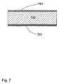
図7は、ガルバニ電池用の典型的な包装箔の基本構造を示す。アルミニウム箔702の一方の側にポリアミド701がコーティングされ、他方の側にポリプロピレン703がコーティングされている。当然、別の材料、層、またはコーティングを備える別の箔も可能である。
FIG. 7 shows the basic structure of a typical packaging foil for galvanic cells. One side of the aluminum foil 702 is coated with
図8は、一体型フレームを備える本発明に係るガルバニ電池から構成される電池ブロックの好ましい一実施形態を示す。完成形の電池ブロック801は、組立て段階にある電池ブロック802に、更なる電池、例えば参照符号803を付された電池をフレームと共に追加することによって構成される。電池803は、本来の電池804に導体805、806を取り付けたものから構成され、これがフレーム807と摩擦結合される。電池ブロック全体を安定させるために、通しボルト808、809、810、および811が、対応する孔を通してフレームに貫入される。
FIG. 8 shows a preferred embodiment of a battery block composed of a galvanic battery according to the present invention having an integral frame. The completed
電池の中心合わせまたは位置合わせを容易にする構造、例えば突起部や溝を備えるようにフレームが形成されている場合、孔を通した通しボルトの貫入もかなり容易になる。この実施形態では、導体が、重量節減のためフレームの周りに巻き付けられまたは折り曲げられ、それによりかさばったコンタクトストリップ(massive Kontaktleiste)が不要になる。 If the frame is formed with a structure that facilitates centering or alignment of the battery, for example, a protrusion or a groove, the penetration of the through bolt through the hole is considerably facilitated. In this embodiment, the conductor is wrapped or folded around the frame to save weight, thereby eliminating the need for bulky contact strips.
図9は、フレームの周りに導体を巻き付けたそのような電池の詳細図である。電池901は、フレーム902の周りに巻き付けられた導体904を有する。フレームには、通しボルトを貫入するための穴903が設けられている。図10は、同じ電池を分解図で示す。図9に示されているものとは異なり、フレーム1002の取付け後に初めて導体1004がフレームの周りで折り曲げられる。図11は、この実施形態のガルバニ電池から構成される電池ブロックを示す。
FIG. 9 is a detailed view of such a battery with a conductor wrapped around the frame. The
図12は、図11に示す電池ブロックの断面図である。電池1201の電池頭部1202に導体1204が取り付けられ、導体1204が、フレーム1205の周りで折り曲げられ、隣接する電池の導体と電気的に接触している。電池1201の反対側の導体は、フレーム1205の周りに折り曲げられておらず、したがって、隣接する電池の導体1206から電気的に絶縁され、この導体1206は、次に隣接する電池の導体と電気的に接触している。このようにして、電池ブロックの組立て時に、実質的に更なる補助手段なしで、導体の所期の電気的接続を達成することができる。
12 is a cross-sectional view of the battery block shown in FIG. A
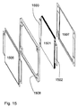
図13に示す本発明の実施形態は、更に小さい空間しか必要としない。電池1301の導体1304は、溶接部と平行に包装材から延出して摩擦接触している。フレーム1302は、通しボルトの貫入用の孔1303を有する。図14はこの実施形態の分解図を示す。電池1401の包装材は、その隅に、フレーム1402との熱圧着に適した特別な平面1405を有する。この場合、電池の導体1404は、自動的に所期の接触が成されるように配置される。さらに、電池の包装材の隅に、通しボルトの貫入用の穴1406を設けることができ、これらは、フレーム1402の対応する開口1403と位置をぴったり重ね合わせて配置されている。図15は、この例示的実施形態の分解図を示す。導体1502、1503を備える電極積層体1501が、包装材の上側部分1506と、フレーム1508と、包装材の下側部分1507との間に封じ込められる。包装材の上側部分および下側部分は、図15に示される形状要素を備え、これらの形状要素は、導体が自動的に所期通りに接触するように助ける。
The embodiment of the invention shown in FIG. 13 requires less space. The
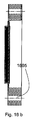
図16は、図19の下側に示したガルバニ電池の3つの異なる切断面16a、16b、および16cを示す。ここで、図16aは、線1907に沿った切断線による断面を示し、図16bは、線1906に沿った切断線による断面を示し、図16cは、線1905に沿った切断線による断面を示す。図16aは、電池頭部1602および電池頭部1603を備える電池積層体1601を示し、図16bは、フレーム1604を通る開口1605を示し、図16cは、電池を通る、図16aに垂直に延在する断面を示す。
FIG. 16 shows three different cut surfaces 16a, 16b and 16c of the galvanic cell shown at the bottom of FIG. Here, FIG. 16a shows a cross section with a cutting line along
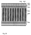
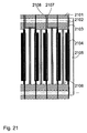
図17は、本発明のこの例示的実施形態のフレーム領域の拡大断面図である。電池1701の包装箔の両部分1702、1703と結合されたフレーム1704が図示されている。図18は、本発明のこの実施形態に係る電池から構成される電池積層体を示す。図20は、図19の上側に示した切断線による電池ブロックの断面を示す。図21は、この断面図の一部の拡大図であり、本発明のこの実施形態では空間が更に効率的に使用されることが図20よりも明瞭に見て取れる。図21の上側に見られる、隣接する電池の導体2108と電気的に接触する導体2107の特別な形態により、ほぼ隙間のない電池ブロック構造が可能になる。電池積層体2104と、包装材の下部2105と、包装材の上部2106と、開口2102を有するフレーム2101およびフレーム2103が認められる。
FIG. 17 is an enlarged cross-sectional view of the frame region of this exemplary embodiment of the present invention. A
101 包装材
102 一体型フレーム
103、104 導体
201 包装材
202 フレーム
203、204 導体
301 電池積層体
302、303 導体
304、305 電極束
306、307 包装箔の部分
308 フレーム
701 ポリアミド
702 アルミニウム箔
703 ポリプロピレン
801 完成形の電池ブロック
802 組立て段階にある電池ブロック
803 電池
804 本来の電池
805、806 導体
807 フレーム
808、809、810、811 通しボルト
901 電池
902 フレーム
903 穴
904 導体
1201 電池
1202 電池頭部
1204 導体
1205 フレーム
1206 導体
1301 電池
1302 フレーム
1303 孔
1304 導体
1701 電池
1702、1703 包装箔の部分
1704 フレーム
101 Packaging materials
102 Integrated frame
103, 104 conductors
201 Packaging materials
202 frames
203, 204 conductors
301 Battery stack
302, 303 conductors
304, 305 Electrode bundle
306, 307 Packaging foil part
308 frames
701 Polyamide
702 aluminum foil
703 polypropylene
801 Complete battery block
802 Battery block in the assembly stage
803 battery
804 Original battery
805, 806 conductor
807 frames
808, 809, 810, 811 through bolt
901 battery
902 frames
903 holes
904 conductor
1201 battery
1202 Battery head
1204 conductor
1205 frames
1206 conductor
1301 battery
1302 frames
1303 hole
1304 conductor
1701 battery
1702, 1703 Packaging foil part
1704 frames
Claims (12)
Applications Claiming Priority (3)
| Application Number | Priority Date | Filing Date | Title |
|---|---|---|---|
| DE102009010794.0 | 2009-02-27 | ||
| DE102009010794A DE102009010794A1 (en) | 2009-02-27 | 2009-02-27 | Galvanic cell with frame and method for its production |
| PCT/EP2010/001260 WO2010097242A1 (en) | 2009-02-27 | 2010-03-01 | Galvanic cell having a frame and method for the production of said galvanic cell |
Publications (2)
| Publication Number | Publication Date |
|---|---|
| JP2012519349A true JP2012519349A (en) | 2012-08-23 |
| JP2012519349A5 JP2012519349A5 (en) | 2013-04-04 |
Family
ID=42167305
Family Applications (1)
| Application Number | Title | Priority Date | Filing Date |
|---|---|---|---|
| JP2011551446A Pending JP2012519349A (en) | 2009-02-27 | 2010-03-01 | Galvanic battery having a frame and manufacturing method thereof |
Country Status (8)
| Country | Link |
|---|---|
| US (1) | US20120135288A1 (en) |
| EP (1) | EP2401779A1 (en) |
| JP (1) | JP2012519349A (en) |
| KR (1) | KR20120006984A (en) |
| CN (1) | CN102334211A (en) |
| BR (1) | BRPI1007834A2 (en) |
| DE (1) | DE102009010794A1 (en) |
| WO (1) | WO2010097242A1 (en) |
Cited By (1)
| Publication number | Priority date | Publication date | Assignee | Title |
|---|---|---|---|---|
| WO2014034932A1 (en) * | 2012-09-03 | 2014-03-06 | Necエナジーデバイス株式会社 | Battery pack |
Families Citing this family (15)
| Publication number | Priority date | Publication date | Assignee | Title |
|---|---|---|---|---|
| DE102010034545A1 (en) | 2010-08-17 | 2012-02-23 | Li-Tec Battery Gmbh | Electrochemical cell with at least one pressure relief device |
| DE102010055610A1 (en) * | 2010-12-22 | 2012-06-28 | Daimler Ag | Battery with a stack of several prismatic battery cells |
| US8980465B2 (en) | 2011-01-05 | 2015-03-17 | Samsung Sdi Co., Ltd. | Battery pack |
| JP2014032789A (en) * | 2012-08-02 | 2014-02-20 | Nissan Motor Co Ltd | Thin battery |
| KR101934396B1 (en) * | 2012-10-30 | 2019-01-02 | 삼성에스디아이 주식회사 | Battery assembly |
| US9711770B2 (en) | 2012-11-27 | 2017-07-18 | Apple Inc. | Laminar battery system |
| US10141600B2 (en) | 2013-03-15 | 2018-11-27 | Apple Inc. | Thin film pattern layer battery systems |
| CN105186040A (en) * | 2014-06-23 | 2015-12-23 | 台达电子工业股份有限公司 | Battery making method |
| US10930915B2 (en) | 2014-09-02 | 2021-02-23 | Apple Inc. | Coupling tolerance accommodating contacts or leads for batteries |
| US20160093837A1 (en) * | 2014-09-30 | 2016-03-31 | Apple Inc. | Efficient Battery Pouch |
| US9755198B2 (en) * | 2015-10-07 | 2017-09-05 | Lg Chem, Ltd. | Battery cell assembly |
| CN105591060B (en) * | 2016-02-25 | 2019-09-03 | 宁德时代新能源科技股份有限公司 | Power battery pack device |
| KR20200070944A (en) * | 2018-12-10 | 2020-06-18 | 현대자동차주식회사 | Elastomer cell frame for fuel cell and manufacturing method thereof and unit cell comprising thereof |
| DE102018221539A1 (en) * | 2018-12-12 | 2020-06-18 | Robert Bosch Gmbh | Battery module unit comprising at least two battery cells |
| US11824220B2 (en) | 2020-09-03 | 2023-11-21 | Apple Inc. | Electronic device having a vented battery barrier |
Citations (7)
| Publication number | Priority date | Publication date | Assignee | Title |
|---|---|---|---|---|
| JP2006019075A (en) * | 2004-06-30 | 2006-01-19 | Nissan Motor Co Ltd | Flat type battery and battery pack using its battery |
| JP2006066322A (en) * | 2004-08-30 | 2006-03-09 | Shin Kobe Electric Mach Co Ltd | Battery pack and module battery |
| JP2006260967A (en) * | 2005-03-17 | 2006-09-28 | Toyota Motor Corp | Battery module |
| WO2006135008A1 (en) * | 2005-06-17 | 2006-12-21 | Nec Lamilion Energy, Ltd. | Electric device assembly and electric device with film outer covering |
| JP2007109548A (en) * | 2005-10-14 | 2007-04-26 | Nec Corp | Electric device assembly and its manufacturing method |
| JP2008535157A (en) * | 2005-03-23 | 2008-08-28 | エスケー エネルギー 株式会社 | Case for high-power rechargeable lithium battery |
| JP2010161044A (en) * | 2009-01-09 | 2010-07-22 | Fdk Corp | Power storage module |
Family Cites Families (6)
| Publication number | Priority date | Publication date | Assignee | Title |
|---|---|---|---|---|
| CA1068780A (en) * | 1977-05-31 | 1979-12-25 | Thomas J. Dougherty | Storage battery with folded plates and separators |
| US5487958A (en) * | 1993-12-06 | 1996-01-30 | Tura; Drew | Interlocking frame system for lithium-polymer battery construction |
| EP0814529A1 (en) * | 1996-06-19 | 1997-12-29 | Koninklijke Philips Electronics N.V. | Thin card containing flat accumulator and connecting devices |
| US20040067416A1 (en) * | 2002-10-07 | 2004-04-08 | Maclean Gregory K. | Protective frame for rechargeable battery cells |
| JP4570888B2 (en) * | 2004-03-18 | 2010-10-27 | 富士重工業株式会社 | Power storage device |
| KR100880386B1 (en) * | 2005-06-03 | 2009-01-23 | 주식회사 엘지화학 | Secondary Battery of Novel Structure and Battery Pack Having the Same |
-
2009
- 2009-02-27 DE DE102009010794A patent/DE102009010794A1/en not_active Withdrawn
-
2010
- 2010-03-01 WO PCT/EP2010/001260 patent/WO2010097242A1/en active Application Filing
- 2010-03-01 JP JP2011551446A patent/JP2012519349A/en active Pending
- 2010-03-01 CN CN201080009624XA patent/CN102334211A/en active Pending
- 2010-03-01 BR BRPI1007834A patent/BRPI1007834A2/en not_active IP Right Cessation
- 2010-03-01 US US13/203,252 patent/US20120135288A1/en not_active Abandoned
- 2010-03-01 KR KR1020117022491A patent/KR20120006984A/en not_active Application Discontinuation
- 2010-03-01 EP EP10707466A patent/EP2401779A1/en not_active Withdrawn
Patent Citations (7)
| Publication number | Priority date | Publication date | Assignee | Title |
|---|---|---|---|---|
| JP2006019075A (en) * | 2004-06-30 | 2006-01-19 | Nissan Motor Co Ltd | Flat type battery and battery pack using its battery |
| JP2006066322A (en) * | 2004-08-30 | 2006-03-09 | Shin Kobe Electric Mach Co Ltd | Battery pack and module battery |
| JP2006260967A (en) * | 2005-03-17 | 2006-09-28 | Toyota Motor Corp | Battery module |
| JP2008535157A (en) * | 2005-03-23 | 2008-08-28 | エスケー エネルギー 株式会社 | Case for high-power rechargeable lithium battery |
| WO2006135008A1 (en) * | 2005-06-17 | 2006-12-21 | Nec Lamilion Energy, Ltd. | Electric device assembly and electric device with film outer covering |
| JP2007109548A (en) * | 2005-10-14 | 2007-04-26 | Nec Corp | Electric device assembly and its manufacturing method |
| JP2010161044A (en) * | 2009-01-09 | 2010-07-22 | Fdk Corp | Power storage module |
Cited By (3)
| Publication number | Priority date | Publication date | Assignee | Title |
|---|---|---|---|---|
| WO2014034932A1 (en) * | 2012-09-03 | 2014-03-06 | Necエナジーデバイス株式会社 | Battery pack |
| JPWO2014034932A1 (en) * | 2012-09-03 | 2016-08-08 | Necエナジーデバイス株式会社 | Battery pack |
| US9634307B2 (en) | 2012-09-03 | 2017-04-25 | Nec Energy Devices, Ltd. | Battery pack |
Also Published As
| Publication number | Publication date |
|---|---|
| KR20120006984A (en) | 2012-01-19 |
| US20120135288A1 (en) | 2012-05-31 |
| DE102009010794A1 (en) | 2010-09-02 |
| BRPI1007834A2 (en) | 2016-02-23 |
| CN102334211A (en) | 2012-01-25 |
| WO2010097242A1 (en) | 2010-09-02 |
| EP2401779A1 (en) | 2012-01-04 |
Similar Documents
| Publication | Publication Date | Title |
|---|---|---|
| JP2012519349A (en) | Galvanic battery having a frame and manufacturing method thereof | |
| JP6721053B2 (en) | Power storage device and method of manufacturing power storage device | |
| JP5046956B2 (en) | Method for manufacturing electrical device assembly | |
| JP5303974B2 (en) | Assembled battery | |
| JP5495192B2 (en) | Film exterior electrical device and battery pack | |
| JP2013502672A (en) | Galvanic battery with frame and method for manufacturing the same | |
| JP5195208B2 (en) | Battery and battery manufacturing method | |
| JP5290520B2 (en) | Thin battery, assembled battery, and method of manufacturing thin battery | |
| JP4690013B2 (en) | Connection apparatus and electrical device assembly using the same | |
| JP2006221938A (en) | Film packaged electric storage device | |
| US10879573B2 (en) | Energy storage apparatus and method of manufacturing energy storage apparatus | |
| KR20160110206A (en) | Laminate type battery and manufacturing method thereof | |
| CN105390741B (en) | Bracket component, lithium ion battery, the assembly method of lithium ion battery | |
| JP5034152B2 (en) | Assembled battery | |
| JP5876380B2 (en) | Method for manufacturing laminated aluminum material and method for manufacturing sealed battery including the same | |
| JP6862639B2 (en) | Heat block | |
| JP2006164922A (en) | Power storage device and member used for manufacture of the same | |
| JP2018041818A (en) | Power storage device, power storage module, and method for manufacturing power storage module | |
| KR101546002B1 (en) | electrochemical energy storage device | |
| JP5725113B2 (en) | Battery pack and film-covered electrical device | |
| JP2010211944A (en) | Power storage device and power storage module | |
| JP4708771B2 (en) | Film exterior electrical device case and film exterior electrical device with case | |
| JP2003331798A (en) | Cladding film for sealing electrode body and sealing method of cladding film | |
| JP5086204B2 (en) | Capacitor module and manufacturing method thereof | |
| JP6077312B2 (en) | Secondary battery |
Legal Events
| Date | Code | Title | Description |
|---|---|---|---|
| A521 | Request for written amendment filed |
Free format text: JAPANESE INTERMEDIATE CODE: A523 Effective date: 20130212 |
|
| A621 | Written request for application examination |
Free format text: JAPANESE INTERMEDIATE CODE: A621 Effective date: 20130212 |
|
| A977 | Report on retrieval |
Free format text: JAPANESE INTERMEDIATE CODE: A971007 Effective date: 20140228 |
|
| A131 | Notification of reasons for refusal |
Free format text: JAPANESE INTERMEDIATE CODE: A131 Effective date: 20140304 |
|
| A02 | Decision of refusal |
Free format text: JAPANESE INTERMEDIATE CODE: A02 Effective date: 20140729 |