KR20200070944A - Elastomer cell frame for fuel cell and manufacturing method thereof and unit cell comprising thereof - Google Patents
Elastomer cell frame for fuel cell and manufacturing method thereof and unit cell comprising thereof Download PDFInfo
- Publication number
- KR20200070944A KR20200070944A KR1020180158663A KR20180158663A KR20200070944A KR 20200070944 A KR20200070944 A KR 20200070944A KR 1020180158663 A KR1020180158663 A KR 1020180158663A KR 20180158663 A KR20180158663 A KR 20180158663A KR 20200070944 A KR20200070944 A KR 20200070944A
- Authority
- KR
- South Korea
- Prior art keywords
- elastic
- frame
- insert
- cell
- fuel cell
- Prior art date
Links
- 239000000446 fuel Substances 0.000 title claims abstract description 54
- 238000004519 manufacturing process Methods 0.000 title claims abstract description 21
- 229920001971 elastomer Polymers 0.000 title abstract 6
- 239000000806 elastomer Substances 0.000 title abstract 6
- 239000012495 reaction gas Substances 0.000 claims abstract description 59
- 239000000498 cooling water Substances 0.000 claims abstract description 40
- 239000012528 membrane Substances 0.000 claims abstract description 37
- 238000009792 diffusion process Methods 0.000 claims abstract description 23
- 239000007789 gas Substances 0.000 claims abstract description 23
- 238000000034 method Methods 0.000 claims abstract description 21
- 238000000926 separation method Methods 0.000 claims description 26
- 239000000853 adhesive Substances 0.000 claims description 23
- 230000001070 adhesive effect Effects 0.000 claims description 23
- 229920002725 thermoplastic elastomer Polymers 0.000 claims description 14
- 230000004927 fusion Effects 0.000 claims description 13
- 238000007789 sealing Methods 0.000 claims description 9
- 238000002360 preparation method Methods 0.000 claims description 8
- 238000003825 pressing Methods 0.000 claims description 6
- 238000005304 joining Methods 0.000 claims description 3
- 238000002844 melting Methods 0.000 claims description 3
- 230000008018 melting Effects 0.000 claims description 3
- 238000000465 moulding Methods 0.000 claims description 2
- 230000002093 peripheral effect Effects 0.000 claims description 2
- 210000004027 cell Anatomy 0.000 description 90
- 239000000758 substrate Substances 0.000 description 7
- 239000000463 material Substances 0.000 description 6
- 239000005518 polymer electrolyte Substances 0.000 description 6
- 239000001257 hydrogen Substances 0.000 description 4
- 229910052739 hydrogen Inorganic materials 0.000 description 4
- XLYOFNOQVPJJNP-UHFFFAOYSA-N water Substances O XLYOFNOQVPJJNP-UHFFFAOYSA-N 0.000 description 4
- 239000002826 coolant Substances 0.000 description 3
- 239000004033 plastic Substances 0.000 description 3
- UFHFLCQGNIYNRP-UHFFFAOYSA-N Hydrogen Chemical compound [H][H] UFHFLCQGNIYNRP-UHFFFAOYSA-N 0.000 description 2
- QVGXLLKOCUKJST-UHFFFAOYSA-N atomic oxygen Chemical compound [O] QVGXLLKOCUKJST-UHFFFAOYSA-N 0.000 description 2
- 239000003054 catalyst Substances 0.000 description 2
- 238000001816 cooling Methods 0.000 description 2
- 238000010586 diagram Methods 0.000 description 2
- 230000000694 effects Effects 0.000 description 2
- 239000003792 electrolyte Substances 0.000 description 2
- -1 hydrogen cations Chemical class 0.000 description 2
- 230000010354 integration Effects 0.000 description 2
- 238000003475 lamination Methods 0.000 description 2
- 239000001301 oxygen Substances 0.000 description 2
- 229910052760 oxygen Inorganic materials 0.000 description 2
- 210000003850 cellular structure Anatomy 0.000 description 1
- 230000006835 compression Effects 0.000 description 1
- 238000007906 compression Methods 0.000 description 1
- 230000007547 defect Effects 0.000 description 1
- 238000007599 discharging Methods 0.000 description 1
- 238000011038 discontinuous diafiltration by volume reduction Methods 0.000 description 1
- 238000010438 heat treatment Methods 0.000 description 1
- 230000001939 inductive effect Effects 0.000 description 1
- 238000001746 injection moulding Methods 0.000 description 1
- 238000010248 power generation Methods 0.000 description 1
- 239000000376 reactant Substances 0.000 description 1
- 239000000126 substance Substances 0.000 description 1
- 229920001169 thermoplastic Polymers 0.000 description 1
- 239000004416 thermosoftening plastic Substances 0.000 description 1
- 239000013585 weight reducing agent Substances 0.000 description 1
Images


Classifications
-
- H—ELECTRICITY
- H01—ELECTRIC ELEMENTS
- H01M—PROCESSES OR MEANS, e.g. BATTERIES, FOR THE DIRECT CONVERSION OF CHEMICAL ENERGY INTO ELECTRICAL ENERGY
- H01M8/00—Fuel cells; Manufacture thereof
- H01M8/10—Fuel cells with solid electrolytes
- H01M8/1004—Fuel cells with solid electrolytes characterised by membrane-electrode assemblies [MEA]
-
- H—ELECTRICITY
- H01—ELECTRIC ELEMENTS
- H01M—PROCESSES OR MEANS, e.g. BATTERIES, FOR THE DIRECT CONVERSION OF CHEMICAL ENERGY INTO ELECTRICAL ENERGY
- H01M8/00—Fuel cells; Manufacture thereof
- H01M8/02—Details
- H01M8/0271—Sealing or supporting means around electrodes, matrices or membranes
- H01M8/0273—Sealing or supporting means around electrodes, matrices or membranes with sealing or supporting means in the form of a frame
-
- H—ELECTRICITY
- H01—ELECTRIC ELEMENTS
- H01M—PROCESSES OR MEANS, e.g. BATTERIES, FOR THE DIRECT CONVERSION OF CHEMICAL ENERGY INTO ELECTRICAL ENERGY
- H01M8/00—Fuel cells; Manufacture thereof
- H01M8/24—Grouping of fuel cells, e.g. stacking of fuel cells
- H01M8/241—Grouping of fuel cells, e.g. stacking of fuel cells with solid or matrix-supported electrolytes
- H01M8/242—Grouping of fuel cells, e.g. stacking of fuel cells with solid or matrix-supported electrolytes comprising framed electrodes or intermediary frame-like gaskets
-
- H—ELECTRICITY
- H01—ELECTRIC ELEMENTS
- H01M—PROCESSES OR MEANS, e.g. BATTERIES, FOR THE DIRECT CONVERSION OF CHEMICAL ENERGY INTO ELECTRICAL ENERGY
- H01M8/00—Fuel cells; Manufacture thereof
- H01M8/02—Details
- H01M8/0202—Collectors; Separators, e.g. bipolar separators; Interconnectors
- H01M8/0258—Collectors; Separators, e.g. bipolar separators; Interconnectors characterised by the configuration of channels, e.g. by the flow field of the reactant or coolant
-
- H—ELECTRICITY
- H01—ELECTRIC ELEMENTS
- H01M—PROCESSES OR MEANS, e.g. BATTERIES, FOR THE DIRECT CONVERSION OF CHEMICAL ENERGY INTO ELECTRICAL ENERGY
- H01M8/00—Fuel cells; Manufacture thereof
- H01M8/02—Details
- H01M8/0202—Collectors; Separators, e.g. bipolar separators; Interconnectors
- H01M8/0267—Collectors; Separators, e.g. bipolar separators; Interconnectors having heating or cooling means, e.g. heaters or coolant flow channels
-
- H—ELECTRICITY
- H01—ELECTRIC ELEMENTS
- H01M—PROCESSES OR MEANS, e.g. BATTERIES, FOR THE DIRECT CONVERSION OF CHEMICAL ENERGY INTO ELECTRICAL ENERGY
- H01M8/00—Fuel cells; Manufacture thereof
- H01M8/02—Details
- H01M8/0271—Sealing or supporting means around electrodes, matrices or membranes
- H01M8/0286—Processes for forming seals
-
- H—ELECTRICITY
- H01—ELECTRIC ELEMENTS
- H01M—PROCESSES OR MEANS, e.g. BATTERIES, FOR THE DIRECT CONVERSION OF CHEMICAL ENERGY INTO ELECTRICAL ENERGY
- H01M8/00—Fuel cells; Manufacture thereof
- H01M8/04—Auxiliary arrangements, e.g. for control of pressure or for circulation of fluids
- H01M8/04007—Auxiliary arrangements, e.g. for control of pressure or for circulation of fluids related to heat exchange
- H01M8/04067—Heat exchange or temperature measuring elements, thermal insulation, e.g. heat pipes, heat pumps, fins
- H01M8/04074—Heat exchange unit structures specially adapted for fuel cell
-
- H—ELECTRICITY
- H01—ELECTRIC ELEMENTS
- H01M—PROCESSES OR MEANS, e.g. BATTERIES, FOR THE DIRECT CONVERSION OF CHEMICAL ENERGY INTO ELECTRICAL ENERGY
- H01M8/00—Fuel cells; Manufacture thereof
- H01M8/04—Auxiliary arrangements, e.g. for control of pressure or for circulation of fluids
- H01M8/04082—Arrangements for control of reactant parameters, e.g. pressure or concentration
- H01M8/04089—Arrangements for control of reactant parameters, e.g. pressure or concentration of gaseous reactants
-
- H—ELECTRICITY
- H01—ELECTRIC ELEMENTS
- H01M—PROCESSES OR MEANS, e.g. BATTERIES, FOR THE DIRECT CONVERSION OF CHEMICAL ENERGY INTO ELECTRICAL ENERGY
- H01M8/00—Fuel cells; Manufacture thereof
- H01M8/04—Auxiliary arrangements, e.g. for control of pressure or for circulation of fluids
- H01M8/04082—Arrangements for control of reactant parameters, e.g. pressure or concentration
- H01M8/04201—Reactant storage and supply, e.g. means for feeding, pipes
-
- H—ELECTRICITY
- H01—ELECTRIC ELEMENTS
- H01M—PROCESSES OR MEANS, e.g. BATTERIES, FOR THE DIRECT CONVERSION OF CHEMICAL ENERGY INTO ELECTRICAL ENERGY
- H01M8/00—Fuel cells; Manufacture thereof
- H01M8/10—Fuel cells with solid electrolytes
- H01M8/1016—Fuel cells with solid electrolytes characterised by the electrolyte material
- H01M8/1018—Polymeric electrolyte materials
-
- H—ELECTRICITY
- H01—ELECTRIC ELEMENTS
- H01M—PROCESSES OR MEANS, e.g. BATTERIES, FOR THE DIRECT CONVERSION OF CHEMICAL ENERGY INTO ELECTRICAL ENERGY
- H01M8/00—Fuel cells; Manufacture thereof
- H01M8/24—Grouping of fuel cells, e.g. stacking of fuel cells
- H01M8/2465—Details of groupings of fuel cells
- H01M8/2483—Details of groupings of fuel cells characterised by internal manifolds
-
- H—ELECTRICITY
- H01—ELECTRIC ELEMENTS
- H01M—PROCESSES OR MEANS, e.g. BATTERIES, FOR THE DIRECT CONVERSION OF CHEMICAL ENERGY INTO ELECTRICAL ENERGY
- H01M8/00—Fuel cells; Manufacture thereof
- H01M8/10—Fuel cells with solid electrolytes
- H01M2008/1095—Fuel cells with polymeric electrolytes
-
- Y—GENERAL TAGGING OF NEW TECHNOLOGICAL DEVELOPMENTS; GENERAL TAGGING OF CROSS-SECTIONAL TECHNOLOGIES SPANNING OVER SEVERAL SECTIONS OF THE IPC; TECHNICAL SUBJECTS COVERED BY FORMER USPC CROSS-REFERENCE ART COLLECTIONS [XRACs] AND DIGESTS
- Y02—TECHNOLOGIES OR APPLICATIONS FOR MITIGATION OR ADAPTATION AGAINST CLIMATE CHANGE
- Y02E—REDUCTION OF GREENHOUSE GAS [GHG] EMISSIONS, RELATED TO ENERGY GENERATION, TRANSMISSION OR DISTRIBUTION
- Y02E60/00—Enabling technologies; Technologies with a potential or indirect contribution to GHG emissions mitigation
- Y02E60/30—Hydrogen technology
- Y02E60/50—Fuel cells
-
- Y—GENERAL TAGGING OF NEW TECHNOLOGICAL DEVELOPMENTS; GENERAL TAGGING OF CROSS-SECTIONAL TECHNOLOGIES SPANNING OVER SEVERAL SECTIONS OF THE IPC; TECHNICAL SUBJECTS COVERED BY FORMER USPC CROSS-REFERENCE ART COLLECTIONS [XRACs] AND DIGESTS
- Y02—TECHNOLOGIES OR APPLICATIONS FOR MITIGATION OR ADAPTATION AGAINST CLIMATE CHANGE
- Y02P—CLIMATE CHANGE MITIGATION TECHNOLOGIES IN THE PRODUCTION OR PROCESSING OF GOODS
- Y02P70/00—Climate change mitigation technologies in the production process for final industrial or consumer products
- Y02P70/50—Manufacturing or production processes characterised by the final manufactured product
Abstract
Description
본 발명은 연료전지용 탄성체 셀 프레임 및 그 제조방법과 이를 이용한 단위 셀에 관한 것으로서, 더욱 상세하게는 한 쌍의 시트형 탄성체 프레임을 사용하여 별도의 접착부재 없이 막전극접합체 및 기체확산층과 일체로 접합되며, 반응가스 및 냉각수를 유동시키는 채널을 형성하는 연료전지용 탄성체 셀 프레임 및 그 제조방법과 이를 이용한 단위 셀에 관한 것이다.The present invention relates to an elastic cell frame for a fuel cell and a method for manufacturing the same and a unit cell using the same, and more specifically, a pair of sheet-like elastic frames is used to integrally join the membrane electrode assembly and the gas diffusion layer without a separate adhesive member. , It relates to an elastic cell frame for a fuel cell forming a channel through which the reaction gas and cooling water flow, and a manufacturing method thereof and a unit cell using the same.
연료전지는 연료가 가지고 있는 화학 에너지를 스택 내에서 전기 화학적으로 반응시켜 전기 에너지로 변환하는 일종의 발전장치로서, 산업용, 가정용 및 차량의 구동 전력을 공급할 뿐만 아니라 휴대용 장치와 같은 소형 전자 제품의 전력공급에 사용될 수 있으며, 최근 고효율의 청정 에너지원으로 점차 그 사용영역이 확대되고 있다.A fuel cell is a kind of power generation device that converts chemical energy of a fuel into electrical energy by electrochemically reacting in a stack, as well as supplying driving power for industrial, household, and vehicle, as well as powering small electronic products such as portable devices. It can be used in recent years, and its use area is gradually expanding as a high-efficiency clean energy source.
일반적인 연료전지의 단위 셀은 가장 안쪽에 막전극접합체(MEA: Membrane-Electrode Assembly)가 위치하는데, 이 막전극접합체는 수소 양이온(Proton)을 이동시켜 줄 수 있는 고분자 전해질막과, 이 고분자 전해질막 양면에 수소와 산소가 반응할 수 있도록 도포된 촉매층, 즉 공기극(cathode) 및 연료극(anode)으로 구성되어 있다.A unit cell of a typical fuel cell is located inside the membrane electrode assembly (MEA: Membrane-Electrode Assembly), which is a polymer electrolyte membrane capable of moving hydrogen cations (Proton), and this polymer electrolyte membrane. It is composed of a catalyst layer applied so that hydrogen and oxygen can react on both sides, that is, a cathode and an anode.
또한, 상기 막전극접합체의 일면과 타면, 즉 공기극 및 연료극이 위치한 바깥 부분에는 반응가스를 공급하고 반응에 의해 발생된 생성수를 배출하는 한 쌍의 분리판이 배치된다. 이때 막전극접합체와 분리판 사이에는 반응가스 및 생성수의 유동을 확산시키거나 원활하게 하는 기체확산층(GDL: Gas Diffusion Layer)이 개재될 수 있다.In addition, a pair of separating plates for supplying a reaction gas and discharging the generated water generated by the reaction are disposed on one surface and the other surface of the membrane electrode assembly, that is, the outside where the cathode and the anode are located. At this time, a gas diffusion layer (GDL) may be interposed between the membrane electrode assembly and the separation plate to diffuse or facilitate the flow of reaction gas and generated water.
한편, 종래에는 단위 셀의 기밀 유지 및 적층 공정에서의 편의를 위하여 막전극접합체와 가스켓을 일체화시킨 막-전극-가스켓 접합체(Membrane-Electrode-Gasket Assembly, MEGA)를 제작하여 사용하기도 하였다.Meanwhile, a membrane-electrode-gasket assembly (MEGA) in which a membrane electrode assembly and a gasket are integrated is manufactured and used in the prior art for convenience in airtightness and lamination of unit cells.
또한, 최근에는 막전극접합체에 기체확산층을 접합한 인서트와 가스켓을 일체화시킨 일체형 프레임이 제안되기도 하였다.In addition, an integrated frame in which an insert and a gasket in which a gas diffusion layer is bonded to a membrane electrode assembly are integrated is recently proposed.
하지만, 종래의 일체형 프레임은 플라스틱 재질의 프레임과 인서트를 접착제를 사용하여 접합시켰다. 또한, 종래의 일체형 프레임을 사용하여 단위 셀을 제작하는 경우에 분리판과 일체형 프레임의 접합을 위하여 별도의 접착 부재 및 실링 부재가 필요하였다. 이러한 공정은 재료비용 및 생산비용을 상승시키는 원인이 되었다.However, in the conventional one-piece frame, the plastic frame and the insert were bonded using an adhesive. In addition, in the case of manufacturing a unit cell using a conventional integral frame, a separate adhesive member and a sealing member were required for bonding the separation plate and the integral frame. This process has caused the cost of materials and production to increase.
상기의 배경기술로서 설명된 사항들은 본 발명의 배경에 대한 이해 증진을 위한 것일 뿐, 이 기술분야에서 통상의 지식을 가진자에게 이미 알려진 종래기술에 해당함을 인정하는 것으로 받아들여져서는 안 될 것이다.The above descriptions as background arts are only for improving understanding of the background of the present invention, and should not be accepted as acknowledging that they correspond to the prior arts already known to those skilled in the art.
본 발명은 한 쌍의 시트형 탄성체 프레임을 사용하여 별도의 접착부재 없이 막전극접합체 및 기체확산층과 일체로 접합되는 연료전지용 탄성체 셀 프레임 및 그 제조방법과 이를 이용한 단위 셀을 제공한다.The present invention provides an elastic cell frame for a fuel cell that is integrally bonded to a membrane electrode assembly and a gas diffusion layer without a separate adhesive member using a pair of sheet-like elastic frames, and a manufacturing method and a unit cell using the same.
또한, 본 발명은 반응가스 및 냉각수를 유동시키는 채널을 형성하는 연료전지용 탄성체 셀 프레임 및 그 제조방법과 이를 이용한 단위 셀을 제공한다.In addition, the present invention provides an elastic cell frame for a fuel cell forming a channel through which reaction gas and cooling water flow, and a manufacturing method thereof and a unit cell using the same.
본 발명의 일 실시형태에 따른 연료전지용 탄성체 셀 프레임은 연료전지의 단위 셀을 구성하는 셀 프레임으로서, 막전극접합체와, 그 양면에 배치되는 한 쌍의 기체확산층이 접합된 인서트와; 상기 인서트의 외곽영역에서 상기 인서트의 테두리 하면과 상면에 각각 배치되는 한 쌍의 시트형 탄성체 프레임이 상호 간에 열융착되어 일체로 형성되고, 상기 인서트가 배치되는 반응면 관통홀이 형성되며, 상기 반응면 관통홀의 외곽영역에는 반응가스 및 냉각수가 유입되는 복수의 유입매니폴드 관통홀이 형성되고, 타측에는 반응가스 및 냉각수가 배출되는 복수의 배출매니폴드 관통홀이 형성되며, 상기 복수의 유입매니폴드 관통홀 중 적어도 어느 하나 이상과 반응면 관통홀 사이 영역에는 반응가스 및 냉각수가 유동되는 유로를 형성하는 유입 랜드돌기가 형성되고, 상기 복수의 배출매니폴드 관통홀 중 적어도 어느 하나 이상과 반응면 관통홀 사이 영역에는 반응가스 및 냉각수가 유동되는 경로를 형성하는 배출 랜드돌기가 형성되는 탄성체 프레임을 포함한다.An elastic cell frame for a fuel cell according to an embodiment of the present invention is a cell frame constituting a unit cell of a fuel cell, comprising: a membrane electrode assembly and an insert in which a pair of gas diffusion layers disposed on both sides thereof are joined; In the outer region of the insert, a pair of sheet-like elastic frames respectively disposed on the lower surface and the upper surface of the insert are heat-sealed to each other and integrally formed, and a reaction surface through-hole in which the insert is disposed is formed, and the reaction surface A plurality of inlet manifold through-holes through which reaction gas and cooling water are introduced are formed in an outer region of the through hole, and a plurality of outlet manifold through-holes through which reaction gas and cooling water are discharged are formed on the other side, and through the plurality of inlet manifolds. Inlet land protrusions forming a flow path through which reaction gas and cooling water flow are formed in a region between at least one of the holes and a reaction surface through hole, and at least one of the plurality of discharge manifold through holes and a reaction surface through hole The inter-region includes an elastic frame in which discharge land protrusions forming a path through which reaction gas and cooling water flow are formed.
상기 탄성체 프레임은, 상기 인서트의 외곽영역에서 상기 인서트의 테두리 하면 및 측면을 둘러싸도록 배치되고, 상기 반응면 관통홀의 내주면에는 상기 인서트의 하면 및 측면을 감싸는 단턱부가 형성되며, 상기 복수의 유입매니폴드 관통홀 중 적어도 어느 하나 이상의 외곽영역과 상기 복수의 배출매니폴드 관통홀 중 적어도 어느 하나 이상의 외곽영역에는 상기 단턱부와 연통되는 안착홈부가 형성되는 제 1 탄성체 프레임과; 상기 인서트의 테두리 상면을 둘러싸도록 배치되면서, 상기 안착홈부에 대응되는 형상으로 연장부가 형성되어 상기 인서트의 테두리에서 상기 탄성체 프레임의 단턱부의 내주면과 안착홈부에 대면되는 제 2 탄성체 프레임으로 이루어지는 것을 특징으로 한다.The elastic frame is disposed in the outer region of the insert so as to surround the bottom and side surfaces of the insert, and an inner circumferential surface of the reaction surface through-hole is formed with a stepped portion surrounding the bottom and side surfaces of the insert, and the plurality of inflow manifolds A first elastic body frame in which at least one outer region of the through-hole and at least one outer region of the plurality of discharge manifold through-holes form a seating groove communicating with the stepped portion; It is arranged so as to surround the upper surface of the rim of the insert, the extension portion is formed in a shape corresponding to the seating groove portion is made of a second elastic frame facing the inner circumferential surface and the seating groove portion of the stepped portion of the elastic frame at the rim of the insert do.
상기 인서트, 제 1 탄성체 프레임 및 제 2 탄성체 프레임 사이에는, 상기 제 1 탄성체 프레임의 단턱부와 상기 인서트의 하면이 대면되어 열융착되는 제 1 융착부와; 상기 제 2 탄성체 프레임, 상기 인서트의 상면 및 안착홈부가 대면되어 열융착되는 제 2 융착부와; 상기 제 1 탄성체 프레임의 단턱부와 상기 인서트의 측면이 대면되어 열융착되는 제 3 융착부가 형성되는 것을 특징으로 한다.Between the insert, the first elastic frame and the second elastic frame, a first fusion portion that is heat-sealed to the lower face of the insert and the stepped portion of the first elastic frame; A second fusion part that is heat-sealed by facing the second elastic frame, the upper surface of the insert and the seating groove; It is characterized in that a third fusion part that is heat-sealed is formed by facing the side of the insert and the stepped portion of the first elastic frame.
상기 제 1 탄성체 프레임과 제 2 탄성체 프레임은 상호 간에 대면되는 영역이 서로 대응되는 경사면을 형성하는 것을 특징으로 한다.The first elastic body frame and the second elastic body frame are characterized in that the regions facing each other form an inclined surface corresponding to each other.
상기 제 1 탄성체 프레임과 제 2 탄성체 프레임은 상호 간에 대면되는 영역이 서로 대응되는 요철구조로 형성되는 것을 특징으로 한다.The first elastic body frame and the second elastic body frame are characterized in that the regions facing each other are formed with uneven structures corresponding to each other.
상기 탄성체 프레임을 형성하는 한 쌍의 시트형 탄성체 프레임은 열가소성 탄성체(TPE)로 형성되는 것을 특징으로 한다.The pair of sheet-like elastic frames forming the elastic frame is characterized in that it is formed of a thermoplastic elastomer (TPE).
상기 유입 랜드돌기 및 배출 랜드돌기는 단면의 폭이 돌출되는 방향으로 점점 좁아지는 것을 특징으로 한다.The inflow land projection and the exhaust land projection are characterized in that the width of the cross section is gradually narrowed in the protruding direction.
한편, 본 발명이 일 실시형태에 따른 연료전지용 탄성체 셀 프레임의 제조방법은 연료전지 스택의 단위 셀을 구성하는 셀 프레임을 제조하는 방법으로서, 막전극접합체의 양면에 각각 기체확산층을 접합하여 인서트를 준비하는 인서트 준비단계와; 반응가스 및 냉각수가 유동되는 경로를 형성하는 유입 랜드돌기 및 배출 랜드돌기가 형성된 한 쌍의 시트형 탄성체 프레임을 준비하는 탄성체 프레임 준비단계와; 상기 인서트를 사이에 두고 상기 한 쌍의 탄성체 프레임을 배치하는 배치단계와; 상기 한 쌍의 탄성체 프레임에 열을 가하면서 압착하여 상호 간을 열융착시켜서 일체로 형성하는 접합단계를 포함한다.On the other hand, the method of manufacturing an elastic cell frame for a fuel cell according to an embodiment of the present invention is a method of manufacturing a cell frame constituting a unit cell of a fuel cell stack, wherein a gas diffusion layer is bonded to both sides of a membrane electrode assembly to insert an insert. An insert preparation step of preparing; An elastic frame preparation step of preparing a pair of sheet-like elastic frames formed with inflow land projections and exhaust land projections forming a path through which reaction gas and cooling water flow; An arrangement step of arranging the pair of elastic frames with the insert in between; It includes a bonding step of pressing the heat while applying heat to the frame of the pair of elastic bodies to mutually heat-seal each other.
상기 탄성체 프레임 준비단계에서 상기 탄성체 프레임은 열가소성 탄성체(TPE)를 시트의 형태로 성형하여 준비하는 것을 특징으로 한다.In the step of preparing the elastic frame, the elastic frame is characterized by preparing a thermoplastic elastomer (TPE) in the form of a sheet.
상기 접합단계는 상기 한 쌍의 탄성체 프레임 사이에 상기 인서트가 개재된 상태에서 상기 한 쌍의 탄성체 프레임이 서로 대면되는 영역 중 일부 또는 전부에 열을 가하면서 압착하여 한 쌍의 탄성체 프레임을 접합시키는 것을 특징으로 한다.In the bonding step, bonding the pair of elastic frames by pressing while applying heat to some or all of the regions where the pair of elastic frames face each other while the insert is interposed between the pair of elastic frames It is characterized by.
상기 접합단계에서 한 쌍의 탄성체 프레임에 가해지는 열은 상기 탄성체 프레임의 용융온도보다 높은 온도인 것을 특징으로 한다.The heat applied to the pair of elastic frames in the bonding step is characterized in that the temperature is higher than the melting temperature of the elastic frame.
상기 접합단계에서는 별도의 접착부재 없이 한 쌍의 탄성체 프레임이 상호 간에 열융착되면서 접합되는 것을 특징으로 한다.In the joining step, a pair of elastic frames are joined while being heat-sealed to each other without a separate adhesive member.
한편, 본 발명의 일 실시형태에 따른 연료전지용 단위 셀은 막전극접합체와; 상기 인서트의 외곽영역에서 상기 인서트의 테두리 하면과 상면에 각각 배치되는 한 쌍의 시트형 탄성체 프레임이 상호 간에 열융착되어 일체로 형성되고, 상기 인서트가 배치되는 반응면 관통홀이 형성되며, 상기 반응면 관통홀의 외곽영역에는 반응가스 및 냉각수가 유입되는 복수의 유입매니폴드 관통홀이 형성되고, 타측에는 반응가스 및 냉각수가 배출되는 복수의 배출매니폴드 관통홀이 형성되며, 상기 복수의 유입매니폴드 관통홀 중 적어도 어느 하나 이상과 반응면 관통홀 사이 영역에는 반응가스 및 냉각수가 유동되는 유로를 형성하는 유입 랜드돌기가 형성되고, 상기 복수의 배출매니폴드 관통홀 중 적어도 어느 하나 이상과 반응면 관통홀 사이 영역에는 반응가스 및 냉각수가 유동되는 경로를 형성하는 배출 랜드돌기가 형성되는 탄성체 프레임을 포함하는 탄성체 셀 프레임과; 상기 탄성체 셀 프레임의 양면에 배치되어 반응가스 및 냉각수의 유동을 유도하는 한 쌍의 분리판을 포함한다.Meanwhile, a unit cell for a fuel cell according to an embodiment of the present invention includes a membrane electrode assembly; In the outer region of the insert, a pair of sheet-like elastic frames respectively disposed on the lower surface and the upper surface of the insert are heat-sealed to each other and integrally formed, and a reaction surface through-hole in which the insert is disposed is formed, and the reaction surface A plurality of inlet manifold through-holes through which reaction gas and cooling water are introduced are formed in an outer region of the through hole, and a plurality of outlet manifold through-holes through which reaction gas and cooling water are discharged are formed on the other side, and through the plurality of inlet manifolds. Inlet land protrusions forming a flow path through which reaction gas and cooling water flow are formed in a region between at least one of the holes and a reaction surface through hole, and at least one of the plurality of discharge manifold through holes and a reaction surface through hole An elastic cell frame including an elastic body frame in which discharge land protrusions forming a path through which reaction gas and cooling water flow are formed; It is disposed on both sides of the elastic cell frame and includes a pair of separation plates that induce the flow of reaction gas and cooling water.
상기 탄성체 셀 프레임과 분리판은 상기 탄성체 셀 프레임이 열융착되어 접합되는 것을 특징으로 한다.The elastic cell frame and the separating plate are characterized in that the elastic cell frame is heat-sealed and joined.
상기 유입 랜드돌기 및 배출 랜드돌기가 상기 분리판에 접하면서 반응가스 및 냉각수가 유동되는 채널이 형성되는 것을 특징으로 한다.It characterized in that a channel through which the reaction gas and the coolant flows is formed while the inlet land protrusion and the outlet land protrusion contact the separation plate.
상기 분리판은 상기 탄성체 셀 프레임의 유입 랜드돌기 및 배출 랜드돌기가 접하는 영역에 상기 유입 랜드돌기 및 배출 랜드돌기의 단부 형상에 대응되는 인입홈이 형성되는 것을 특징으로 한다.The separating plate is characterized in that an inlet groove corresponding to the end shape of the inlet land protrusion and the outlet land protrusion is formed in a region in contact with the inlet land protrusion and the outlet land protrusion of the elastic cell frame.
상기 분리판은 상기 탄성체 셀 프레임의 유입 랜드돌기 및 배출 랜드돌기가 접하는 영역을 둘러싸는 가이드 돌기가 형성되는 것을 특징으로 한다.The separation plate is characterized in that a guide protrusion is formed surrounding an area where the inlet and protrusion land protrusions of the elastic cell frame contact.
본 발명의 실시예에 따르면 다음과 같은 효과가 있다.According to an embodiment of the present invention has the following effects.
첫째, 분리판 또는 인서트와의 계면 접합을 위해 별도의 접착 부재가 불필요하고, 이에 따라 재료비 저감 및 접착제 도포 공정 등을 삭제하여 제조 비용을 절감할 수 있다.First, a separate adhesive member is not required for interfacial bonding with the separator or insert, and accordingly, the manufacturing cost can be reduced by reducing the material cost and the adhesive application process.
둘째, 별도의 실링 부재 없이 반응영역의 기밀을 확보할 수 있고, 실링 부재가 불필요하게 됨에 따라 재료비 저감 및 씰링 부재 성형 공정 등을 삭제하여 제조 비용을 절감할 수 있다.Second, the airtightness of the reaction region can be secured without a separate sealing member, and the manufacturing cost can be reduced by eliminating the material cost and sealing member forming process as the sealing member becomes unnecessary.
셋째, 반응영역에서 생성된 수분이 전해질막을 통하여 셀 외부로 확산되는 것을 원천 차단할 수 있기에 셀 간 전기적 쇼트를 방지할 수 있고, 수분에 누출에 의한 연료전지 스택이 부식되는 것을 방지할 수 있다.Third, it is possible to prevent the electrical short circuit between cells because the source generated from the diffusion of water generated in the reaction region to the outside of the cell through the electrolyte membrane can be prevented, and the fuel cell stack due to leakage of water can be prevented from being corroded.
넷째, 반응영역 이외의 영역에 사용되던 전해질막을 사용하지 않아도 되기 때문에, 재료비 측면에서 원가를 절감시킬 수 있다.Fourth, since it is not necessary to use the electrolyte membrane used in a region other than the reaction region, cost can be reduced in terms of material cost.
다섯째, 종래의 플라스틱 프레임 대비 셀 피치 저감에 유리하고, 부피 저감을 통한 스택 소형화를 이룰 수 있다. Fifth, it is advantageous for reducing the cell pitch compared to the conventional plastic frame, and it is possible to achieve a compact size of the stack through volume reduction.
여섯째, 종래의 플라스틱 프레임에 접착 부재 및 실링 부재를 사용하는 것과 비교하여 중량 저감의 효과를 기대할 수 있다.Sixth, the effect of weight reduction can be expected compared with the use of an adhesive member and a sealing member in a conventional plastic frame.
일곱째, 연료전지의 스택 적층시 일체화 공정 축소로 생산 라인 단순화 및 스택 생산성(셀 적층성)을 향상시킬 수 있다.Seventh, it is possible to simplify the production line and improve stack productivity (cell stackability) by reducing the integration process when stacking fuel cells in a stack.
여덟째, 단위 셀 구성 부품을 금형 내 안착 후 열융착하여 일체화함으로써, 인서트와의 접합 정밀도를 향상시킬 수 있어 불량률 저감 및 대량생산을 기대할 수 있다.Eighth, it is possible to improve the bonding precision with the insert by integrating the unit cell component parts after being seated in the mold and heat-sealing, thereby reducing defect rates and expecting mass production.
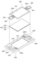
도 1은 본 발명의 일 실시예에 따른 연료전지용 탄성체 셀 프레임을 보여주는 분해사시도이고,
도 2는 본 발명의 일 실시예에 따른 연료전지용 탄성체 셀 프레임을 보여주는 분해사시도이며,
도 3a 및 도 3b는 본 발명의 일 실시예에 따른 연료전지용 탄성체 셀 프레임을 보여주는 요부 단면도이고,
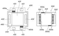
도 4 및 도 5는 본 발명의 다른 실시예에 따른 연료전지용 탄성체 셀 프레임을 보여주는 구성도이며,
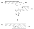
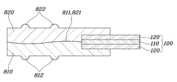
도 6 내지 도 8은 본 발명의 다양한 실시예에 따른 제 1 탄성체 프레임과 제 2 탄성체 프레임의 접촉면 관계를 보여주는 요부 단면 구성도이고,
도 9는 본 발명의 다양한 실시예에 따른 제 1 탄성체 프레임과 제 2 탄성체 프레임의 접촉면 관계를 보여주는 평면 구성도이며,
도 10 내지 도 13은 본 발명의 다양한 실시예에 따른 탄성체 셀 프레임과 분리판의 연결 관계를 보여주는 요부 단면도이다.1 is an exploded perspective view showing an elastic cell frame for a fuel cell according to an embodiment of the present invention,
2 is an exploded perspective view showing an elastic cell frame for a fuel cell according to an embodiment of the present invention,
3A and 3B are sectional views of main parts showing an elastic cell frame for a fuel cell according to an embodiment of the present invention;
4 and 5 is a block diagram showing an elastic cell frame for a fuel cell according to another embodiment of the present invention,
6 to 8 are cross-sectional views of main parts showing a contact surface relationship between a first elastic frame and a second elastic frame according to various embodiments of the present invention,
9 is a plan view showing a contact surface relationship between the first elastic frame and the second elastic frame according to various embodiments of the present invention;
10 to 13 are sectional views of main parts showing a connection relationship between an elastic cell frame and a separation plate according to various embodiments of the present disclosure.
이하, 첨부된 도면을 참조하여 본 발명의 실시예를 더욱 상세히 설명하기로 한다. 그러나 본 발명은 이하에서 개시되는 실시예에 한정되는 것이 아니라 서로 다른 다양한 형태로 구현될 것이며, 단지 본 실시예들은 본 발명의 개시가 완전하도록 하며, 통상의 지식을 가진 자에게 발명의 범주를 완전하게 알려주기 위해 제공되는 것이다. 도면상에서 동일 부호는 동일한 요소를 지칭한다.Hereinafter, embodiments of the present invention will be described in more detail with reference to the accompanying drawings. However, the present invention is not limited to the embodiments disclosed below, but will be implemented in various different forms, and only the present embodiments allow the disclosure of the present invention to be complete, and the scope of the invention to those skilled in the art is completely It is provided to inform you. The same reference numerals in the drawings refer to the same elements.
도 1은 본 발명의 일 실시예에 따른 연료전지용 탄성체 셀 프레임을 보여주는 분해사시도이고, 도 2는 본 발명의 일 실시예에 따른 연료전지용 탄성체 셀 프레임을 보여주는 분해사시도이며, 도 3a 및 도 3b는 본 발명의 일 실시예에 따른 연료전지용 탄성체 셀 프레임을 보여주는 요부 단면도이다. 이때, 도 3a는 도 1의 A-A선에 대한 단면이고, 도 3b는 도 1의 B-B선에 대한 단면이다.1 is an exploded perspective view showing an elastic cell frame for a fuel cell according to an embodiment of the present invention, and FIG. 2 is an exploded perspective view showing an elastic cell frame for a fuel cell according to an embodiment of the present invention, FIGS. 3A and 3B are It is a sectional view of the main parts showing an elastic cell frame for a fuel cell according to an embodiment of the present invention. At this time, FIG. 3A is a cross-section taken along line A-A in FIG. 1, and FIG. 3B is a cross-section taken along line B-B in FIG. 1.
도면에 도시된 바와 같이 본 발명의 일 실시예에 따른 연료전지용 탄성체 셀 프레임은 한 쌍의 분리판과 함께 연료전지의 단위 셀을 구성하는 요소로서, 막전극접합체(110)와 그 양면에 배치되는 한 쌍의 기체확산층(120)이 접합된 인서트(100)와; 열융착에 의해 상기 인서트(100)의 외곽영역에 일체로 형성되면서 분리판(10)과의 접촉에 의해 반응가스 및 냉각수가 유동되는 채널이 형성되는 탄성체 프레임(210, 220)을 포함한다.As shown in the figure, an elastic cell frame for a fuel cell according to an embodiment of the present invention is an element constituting a unit cell of a fuel cell together with a pair of separator plates, and is disposed on both sides of the
인서트(100)는 막전극접합체(110)와 한 쌍의 기체확산층(120)을 적층시킨 접합체로서, 바람직하게는 막전극접합체(110)의 일면 및 타면에 기체확산층(120)이 각각 배치되어 적층된다.The
막전극접합체(110)는 수소 양이온(Proton)을 이동시켜 줄 수 있는 고분자 전해질막과, 이 고분자 전해질막 양면에 수소와 산소가 반응할 수 있도록 도포된 촉매층, 즉 공기극(cathode) 및 연료극(anode)으로 구성되는 일반적인 막전극접합체로 구현된다.The
기체확산층(120)은 분리판을 통하여 유동되는 반응가스를 막전극접합체(110)로 확산시키면서 통과시키는 수단으로서, 기재 단독으로 이루어지거나 기재와, 기재의 일면으로 형성되는 미세기공층(MPL)으로 이루어진다. 이때 기재 및 미세기공층의 소재는 일반적인 기체확산층에 적용되는 소재로 구현된다.The
탄성체 프레임(200, 300)은 인서트(100)의 기밀 유지 및 적층 공정에서의 편의를 위하여 인서트(100)의 외곽영역에 일체로 형성되는 수단으로서, 탄성체 프레임(200, 300)은 소정의 형상을 유지하면서 별도의 접착부재 없이 열융착에 의해 접착하기 위하여 열가소성 탄성체(TPE; Thermo Plastic Elastomer)로 형성된다.The elastic frame (200, 300) is a means that is integrally formed in the outer region of the
특히, 탄성체 프레임(200, 300)은 인서트(100)가 배치되는 반응면 관통홀(210, 310)이 형성되며, 반응면 관통홀(210, 310)의 외곽영역에는 반응가스 및 냉각수가 유입되는 복수의 유입매니폴드 관통홀(220, 322a)이 형성되고, 타측에는 반응가스 및 냉각수가 배출되는 복수의 배출매니폴드 관통홀(230, 322b)이 형성된다. 그리고, 복수의 유입매니폴드 관통홀(220, 322a) 중 적어도 어느 하나 이상과 반응면 관통홀(210, 310) 사이 영역에는 반응가스 및 냉각수가 유동되는 유로를 형성하는 유입 랜드돌기(260a, 321a)가 형성되고, 복수의 배출매니폴드 관통홀(230, 322b) 중 적어도 어느 하나 이상과 반응면 관통홀(210, 310) 사이 영역에는 반응가스 및 냉각수가 유동되는 경로를 형성하는 배출 랜드돌기(260b, 321b)가 형성된다.In particular, the elastic frame (200, 300) is formed through the reaction surface through-holes (210, 310) in which the
부연하자면, 탄성체 프레임(200, 300)은 인서트(100)의 외곽영역에서 인서트(100)의 테두리 하면과 상면에 각각 배치되는 한 쌍의 시트형 탄성체 프레임(200, 300)이 상호 간에 열융착되어 일체로 형성된다. 여기서 인서트(100)의 '외곽영역'이란 인서트(100)의 가장자리 영역과 그 주변의 공간을 포함하는 영역을 의미하고, 인서트(100)의 '테두리'란 인서트(100)의 가장자리 영역을 의미한다.In other words, the elastic frame (200, 300) is a pair of sheet-like elastic frame (200, 300) disposed on the lower surface and the upper surface of the edge of the insert (100) in the outer region of the insert (100) are integrally heat-sealed to each other It is formed of. Here, the'outer area' of the
예를 들어, 도 2에 도시된 바와 같이 탄성체 프레임(200, 300)은 인서트(100)의 테두리 하면 및 측면을 둘러싸도록 배치되는 제 1 탄성체 프레임(200)과; 인서트(100)의 테두리 상면을 둘러싸도록 배치되는 제 2 탄성체 프레임(300)으로 이루어진다. 이때 인서트(100)의 테두리에서 제 1 탄성체 프레임(200)과 제 2 탄성체 프레임(300)이 서로 중첩된다.For example, as shown in FIG. 2, the
부연하자면, 제 1 탄성체 프레임(200)은 인서트(100)의 외곽영역에서 인서트(100)의 테두리 하면 및 측면을 둘러싸도록 배치되는데, 이때 제 1 탄성체 프레임(200)에는 인서트(100)가 배치되는 제 1 반응면 관통홀(210)이 형성되고, 제 1 반응면 관통홀(210)의 내주면에는 인서트(100)의 하면 및 측면을 감싸는 단턱부(240)가 형성된다. 그리고, 복수의 제 1 유입매니폴드 관통홀(220) 중 적어도 어느 하나 이상의 외곽영역과 복수의 제 2 배출매니폴드 관통홀(230) 중 적어도 어느 하나 이상의 외곽영역에는 단턱부(240)와 연통되는 안착홈부(250)가 형성된다. 예를 들어 도 2에 도시된 바와 같이 안착홈부(250)는 제 1 탄성체 프레임(200)의 일측에 3개가 일렬로 형성되는 제 1 유입매니폴드 관통홀(220)과 제 1 탄성체 프레임(200)의 타측에 3개가 일렬로 형성되는 제 1 배출매니폴드 관통홀(230) 중 각각 중앙에 형성되어 냉각수가 유동되는 제 1 유입매니폴드 관통홀(220)과 제 1 배출매니폴드 관통홀(230)의 외곽영역에 형성될 수 있다.In other words, the first
그리고, 제 1 탄성체 프레임(200)에 형성된 3 개의 제 1 유입매니폴드 관통홀(220) 중 반응가스가 유동되는 제 1 유입매니폴드 관통홀(220)과 제 1 반응면 관통홀(210) 사이 영역에는 반응가스가 유동되는 유로를 형성하는 제 1 유입 랜드돌기(260a)가 형성되고, 제 1 탄성체 프레임(200)에 형성된 3 개의 제 1 배출매니폴드 관통홀(230) 중 반응가스가 유동되는 제 1 배출매니폴드 관통홀(230)과 제 1 반응면 관통홀(210) 사이 영역에는 반응가스가 유동되는 유로를 형성하는 제 1 배출 랜드돌기(260b)가 형성된다.And, between the first inlet manifold through-
그리고, 제 2 탄성체 프레임(300)은 인서트(100)의 테두리 상면을 둘러싸도록 배치되는데, 이때 제 2 탄성체 프레임(300)에는 인서트(100)가 배치되는 제 2 반응면 관통홀(310)이 형성되고, 제 1 탄성체 프레임(200)에 형성된 안착홈부(250)에 대응되는 형상으로 연장부(320)가 형성되어 인서트(100)의 테두리에서 제 1 탄성체 프레임(200)에 형성된 단턱부(240)의 내주면과 안착홈부(250)에 대면되도록 형성된다.In addition, the second
이때 제 2 탄성체 프레임(300)의 연장부(320)에는 제 1 탄성체 프레임(200)에 형성된 제 1 유입 매니폴드 관통홀(220) 및 제 1 배출매니폴드 관통홀(230)에 대응되는 형상 및 위치에 제 2 유입 매니폴드 관통홀(322a) 및 제 2 배출매니폴드 관통홀(322b)이 형성된다. 이때 제 2 유입 매니폴드 관통홀(322a) 및 제 2 배출매니폴드 관통홀(322b)의 개수는 연장부가 형성되는 영역에 형성된 제 1 유입 매니폴드 관통홀(220) 및 제 1 배출매니폴드 관통홀(230)의 개수에 대응되도록 형성된다.At this time, the shape corresponding to the first inlet manifold through-
그리고, 제 2 탄성체 프레임(300)의 연장부(320) 중 제 2 유입매니폴드 관통홀(322a)과 제 2 반응면 관통홀(310) 사이 영역에는 반응가스가 유동되는 유로를 형성하는 제 2 유입 랜드돌기(321a)가 형성되고, 제 2 탄성체 프레임(300)의 연장부(320) 중 제 2 배출매니폴드 관통홀(322b)과 제 2 반응면 관통홀(310) 사이 영역에는 반응가스가 유동되는 유로를 형성하는 제 2 배출 랜드돌기(321b)가 형성된다.In addition, a second flow path forming a flow path through which the reaction gas flows is formed in the region between the second inflow manifold through-
한편, 인서트(100), 제 1 탄성체 프레임(200) 및 제 2 탄성체 프레임(300) 사이에는, 각각 서로 대면되는 계면에 열융착에 의한 융착부가 형성되어 상호간에 견고한 접합 및 일체화가 이루어진다.On the other hand, between the
부연하자면, 도 3a에 도시된 바와 같이 제 1 탄성체 프레임(200)의 단턱부(240)와 인서트(100)의 하면이 대면되어 열융착되는 제 1 융착부(H1)와; 제 2 탄성체 프레임(300), 인서트(100)의 상면 및 안착홈부(250)가 대면되어 열융착되는 제 2 융착부(H2)와; 제 1 탄성체 프레임(200)의 단턱부(240)와 인서트(100)의 측면이 대면되어 열융착되는 제 3 융착부(H3)가 형성된다.In more detail, as shown in FIG. 3A, a first fusion part H1 in which a bottom surface of the first
한편, 본 발명에 따른 탄성체 프레임은 그 형상을 변경하여 구현될 수 있다.Meanwhile, the elastic frame according to the present invention may be implemented by changing its shape.
도 4 및 도 5는 본 발명의 다른 실시예에 따른 연료전지용 탄성체 셀 프레임을 보여주는 구성도이다.4 and 5 is a block diagram showing an elastic cell frame for a fuel cell according to another embodiment of the present invention.
먼저, 도 4에 도시된 바와 같이 본 발명의 다른 실시예에 따른 연료전지용 탄성체 셀 프레임은 전술된 실시예와 마찬가지로 인서트(100)와 탄성체 프레임(200, 300)을 포함한다. 이때 인서트(100)는 전술된 실시예의 인서트(100)와 동일하다.First, as shown in FIG. 4, the fuel cell elastic cell frame according to another embodiment of the present invention includes the
그리고, 탄성체 프레임(200, 300)도 전술된 실시예와 마찬가지로 제 1 탄성체 프레임(200)과 제 2 탄성체 프레임(300)으로 이루어진다. 다만, 제 1 탄성체 프레임(200)에 형성되는 안착홈부(250)의 위치 및 개수와 제 2 탄성체 프레임(300)에 형성되는 연장부(320)의 위치 및 개수가 변경된다.And, the elastic frame (200, 300) is also made of the first
예를 들어, 도 4에 도시된 바와 같이 제 1 탄성체 프레임(200)에 형성되는 안착홈부(250)는 3개가 형성된 제 1 유입매니폴드 관통홀(220) 중 양측 측방에 형성되어 반응가스를 유동시키는 제 1 유입매니폴드 관통홀(220)의 외곽영역에 형성될 수 있다. 그리고, 제 1 탄성체 프레임(200)에 형성된 3 개의 제 1 유입매니폴드 관통홀(220) 중 반응가스가 유동되는 제 1 유입매니폴드 관통홀(220)과 제 1 반응면 관통홀(210) 사이 영역에는 반응가스가 유동되는 유로를 형성하는 제 1 유입 랜드돌기(260a)가 형성되고, 제 1 탄성체 프레임(200)에 형성된 3 개의 제 1 배출매니폴드 관통홀(230) 중 반응가스가 유동되는 제 1 배출매니폴드 관통홀(230)과 제 1 반응면 관통홀(210) 사이 영역에는 반응가스가 유동되는 유로를 형성하는 제 1 배출 랜드돌기(260b)가 형성된다.For example, as illustrated in FIG. 4, seating
그리고, 제 2 탄성체 프레임(300)은 인서트(100)가 배치되는 제 2 반응면 관통홀(310)이 형성되고, 제 1 탄성체 프레임(200)에 형성된 안착홈부(250)에 대응되는 형상으로 연장부(320)가 형성되어 인서트(100)의 테두리에서 제 1 탄성체 프레임(200)에 형성된 단턱부(240)의 내주면과 안착홈부(250)에 대면되도록 형성된다.In addition, the second
이때 제 2 탄성체 프레임(300)의 연장부(320)에는 제 1 탄성체 프레임(200)에 형성된 제 1 유입 매니폴드 관통홀(220) 및 제 1 배출매니폴드 관통홀(230)에 대응되는 형상 및 위치에 제 2 유입 매니폴드 관통홀(322a) 및 제 2 배출매니폴드 관통홀(322b)이 형성된다. 그리고, 제 2 탄성체 프레임(300)의 연장부(320) 중 제 2 유입매니폴드 관통홀(322a)과 제 2 반응면 관통홀(310) 사이 영역에는 반응가스가 유동되는 유로를 형성하는 제 2 유입 랜드돌기(321a)가 형성되고, 제 2 탄성체 프레임(300)의 연장부(320) 중 제 2 배출매니폴드 관통홀(322b)과 제 2 반응면 관통홀(310) 사이 영역에는 반응가스가 유동되는 유로를 형성하는 제 2 배출 랜드돌기(321b)가 형성된다.At this time, the shape corresponding to the first inlet manifold through-
다음으로, 도 5에 도시된 바와 같이 본 발명의 또 다른 실시예에 따른 연료전지용 탄성체 셀 프레임은 전술된 실시예와 마찬가지로 인서트(100)와 탄성체 프레임(400, 500을) 포함한다. 이때 인서트는 전술된 실시예의 인서트(100)와 동일하다.Next, as shown in FIG. 5, the elastic cell frame for a fuel cell according to another embodiment of the present invention includes an
그리고, 탄성체 프레임(400, 500)도 전술된 실시예와 마찬가지로 제 1 탄성체 프레임(400)과, 제 2 탄성체 프레임(500)으로 이루어진다. 다만, 탄성체 프레임(400, 500)에 형성되는 복수의 유입매니폴드 관통홀(421, 422)과 복수의 배출매니폴드 관통홀(431, 432)의 위치 변경에 따라 제 1 탄성체 프레임(400)에 형성되는 안착홈부(460)의 위치 및 개수와 제 2 탄성체 프레임(500)의 형상이 변경된다.And, the elastic frame (400, 500) is also made of the first
예를 들어, 도 5에 도시된 바와 같이 제 1 탄성체 프레임(400)에는 인서트(100)가 배치되는 제 1 반응면 관통홀(410)이 형성되고, 제 1 반응면 관통홀(410)의 내주면에는 인서트(100)의 하면 및 측면을 감싸는 단턱부(440)가 형성된다. 그리고, 도면을 기준으로 제 1 탄성체 프레임(400)에는 반응가스가 유동되는 2개의 제 1 유입매니폴드 관통홀(421)이 상부에 형성되고, 냉각수가 유동되는 1개의 제 1 유입매니폴드 관통홀(422)이 좌측부에 형성되며, 냉각수가 유동되는 1개의 제 1 배출매니폴드 관통홀(432)이 우측부에 형성되고, 반응가스가 유동되는 2개의 제 1 배출매니폴드 관통홀(431)이 하부에 형성된다.For example, as illustrated in FIG. 5, a first reaction surface through
또한, 제 1 탄성체 프레임(400)에는 냉각수가 유동되는 제 1 유입매니폴드 관통홀(422) 및 제 1 배출매니폴드 관통홀(432)의 외곽영역과 인서트(100)의 외곽영역에 해당되는 영역에 안착홈부(460)가 형성된다.In addition, the first
그리고, 제 1 탄성체 프레임(400)에는 반응가스가 유동되는 제 1 유입매니폴드 관통홀(421)과 제 1 반응면 관통홀(410) 사이 영역에 반응가스가 유동되는 유로를 형성하는 제 1 유입 랜드돌기(450a)가 형성되고, 제 1 탄성체 프레임(400)에는 반응가스가 유동되는 제 1 배출매니폴드 관통홀(431)과 제 1 반응면 관통홀(410) 사이 영역에 반응가스가 유동되는 유로를 형성하는 제 1 배출 랜드돌기(450b)가 형성된다. 이때 제 2 탄성체 프레임(500)에는 상기 제 1 유입 랜드돌기(450a) 및 제 1 배출 랜드돌기(450b)와 인서트(100)가 배치된 영역 사이를 연장시키는 제 1 유입연장 랜드돌기(550a) 및 제 1 배출연장 랜드돌기(550b)가 형성될 수 있다.In addition, a first inflow to form a flow path through which the reaction gas flows in the region between the first inlet manifold through-
그리고, 제 2 탄성체 프레임(500)는 제 1 탄성체 프레임(400)에 형성된 단턱부(440) 및 안착홈부(460)이 형성되는 영역에 대응되는 형상으로 이루어져서, 인서트(100)가 배치되는 제 2 반응면 관통홀(510)이 형성된다.In addition, the second
그리고, 제 2 탄성체 프레임(500)에는 제 1 탄성체 프레임(400)에 형성된 제 1 유입 매니폴드 관통홀(422) 및 제 1 배출매니폴드 관통홀(432)에 대응되는 형상 및 위치에 제 2 유입 매니폴드 관통홀(521) 및 제 2 배출매니폴드 관통홀(522)이 형성된다. 그리고, 제 2 탄성체 프레임(500)에는 제 2 유입매니폴드 관통홀(521)과 제 2 반응면 관통홀(510) 사이 영역에 냉각수가 유동되는 유로를 형성하는 제 2 유입 랜드돌기(530a)가 형성되고, 제 2 배출매니폴드 관통홀(522)과 제 2 반응면 관통홀(510) 사이 영역에는 냉각수가 유동되는 유로를 형성하는 제 2 배출 랜드돌기(530b)가 형성된다.Then, the second
한편, 본 발명은 탄성체 프레임을 형성하는 한 쌍의 시트형 탄성체 프레임의 계면 형상을 변경하여 상호 간의 접착력을 향상시킬 수 있다.On the other hand, the present invention can improve the adhesion between each other by changing the interface shape of the pair of sheet-like elastic frame forming the elastic frame.
도 6 내지 도 8은 본 발명의 다양한 실시예에 따른 제 1 탄성체 프레임과 제 2 탄성체 프레임의 접촉면 관계를 보여주는 요부 단면 구성도이고,6 to 8 are cross-sectional views of main parts showing a contact surface relationship between a first elastic frame and a second elastic frame according to various embodiments of the present invention,
도 6 내지 도 8은 도 1의 C-C선에 대한 단면에 해당되는 도면이다.6 to 8 are views corresponding to cross-sections taken along line C-C in FIG. 1.
먼저, 도 6에 도시된 바와 같이 제 1 탄성체 프레임(610)과 제 2 탄성체 프레임(620)은 상호 간에 대면되는 영역이 서로 대응되는 경사면(612, 621)을 형성할 수 있다.First, as illustrated in FIG. 6, the first
예를 들어 제 2 탄성체 프레임(620)의 측부를 경사면(621)으로 형성하고, 제 1 탄성체 프레임(610) 중 단턱부(611)가 형성되는 내주면을 제 2 탄성체 프레임(620)의 측부 경사면(621)에 대응되는 경사면(612)으로 형성할 수 있다. 이렇게 상호간의 계면을 경사면(612, 621)으로 형성하여 계면의 면적을 확장시킴으로써 상호 간의 접착력을 향상시킬 수 있다.For example, a side of the second
또한, 도 7에 도시된 바와 같이 제 1 탄성체 프레임(710)과 제 2 탄성체 프레임(720)은 상호 간에 대면되는 영역이 서로 대응되는 요철구조로 형성될 수 있다.In addition, as illustrated in FIG. 7, the first
예를 들어 제 2 탄성체 프레임(720)의 측면 및 하면에 다수의 접착돌기(721)를 형성하고, 제 1 탄성체 프레임(710)의 내주면 및 단턱부(711) 중 접착돌기(721)가 형성된 위치에 대응되는 위치에 상기 접착돌기(721)가 인입되는 접착홈(712)을 형성할 수 있다. 이렇게 상호간의 계면에 형성된 접착돌기(721)와 접합홈(712)의 구조에 의해 계면의 면적을 확장시킴으로써 상호 간의 접착력을 향상시킬 수 있다.For example, a plurality of
이때 접착돌기(721) 및 접합홈(712)의 단면 형상은 도 7에 도시된 바와 같이 반원형으로 형성될 수 있지만, 이에 한정되지 않고 사각형, 삼각형 및 타원형과 같이 다양한 형상으로 변경되어 구현될 수 있다.At this time, the cross-sectional shape of the
또한, 도 8에 도시된 바와 같이 제 1 탄성체 프레임(810)과 제 2 탄성체 프레임(820)은 상호 간에 대면되는 영역을 곡면(811, 821)으로 형성하여 제 1 탄성체 프레임(810)과 제 2 탄성체 프레임(820)의 계면 면적을 확장시킬 수 있다.In addition, as illustrated in FIG. 8, the first
그리고, 도 9는 본 발명의 다양한 실시예에 따른 제 1 탄성체 프레임과 제 2 탄성체 프레임의 접촉면 관계를 보여주는 평면 구성도로서, 도 1의 C-C선 영역의 평면도를 보여주는 구성도이다.And, FIG. 9 is a plan view showing the relationship between the contact surfaces of the first elastic frame and the second elastic frame according to various embodiments of the present invention, and is a schematic view showing a plan view of the region C-C of FIG. 1.
도 9에 도시된 바와 같이 제 1 탄성체 프레임(910)과 제 2 탄성체 프레임(920)은 상호 간에 대면되는 영역이 서로 대응되는 요철구조로 형성될 수 있다.As illustrated in FIG. 9, the first elastic frame 910 and the second
예를 들어 제 1 탄성체 프레임(910)과 제 2 탄성체 프레임(920)은 상호 간에 대면되는 측면에는 다수의 접착돌기(912, 921)와 이에 대응되는 접착홈(911, 922)이 형성되어 서로 인입되어 접촉된다. 이렇게 상호 간의 계면에 형성된 접착돌기(912, 921)와 접합홈(911, 922)의 구조에 의해 계면의 면적을 확장시킴으로써 상호 간의 접착력을 향상시킬 수 있다.For example, the first elastic frame 910 and the second
이때도 마찬가지로 접착돌기(912, 921)와 접합홈(911, 922)의 단면 형상은 도 9에 도시된 바와 같이 반원형으로 형성될 수 있지만, 이에 한정되지 않고 사각형, 삼각형 및 타원형과 같이 다양한 형상으로 변경되어 구현될 수 있다.In this case, similarly, the cross-sectional shape of the
한편, 도 8에 도시된 바와 같이 탄성체 프레임에는 분리판과의 기밀 및 접착을 위한 수단이 형성될 수 있다.Meanwhile, as illustrated in FIG. 8, a means for airtightness and adhesion to the separating plate may be formed on the elastic frame.
예를 들어 제 1 탄성체 프레임(810)의 하면에는 인서트(100)의 외곽영역을 따라 인서트(100)를 둘러싸는 적어도 하나 이상의 제 1 돌기씰(812)이 형성된다. 그리고 제 2 탄성체 프레임(820)의 상면에는 인서트(100)의 외곽영역을 따라 인서트(100)를 둘러싸는 적어도 하나 이상의 제 2 돌기씰(822)이 형성된다.For example, at least one
한편, 상기와 같이 구성되는 연료전지용 탄성체 셀 프레임을 제조하는 방법에 대하여 설명한다.Meanwhile, a method of manufacturing an elastic cell frame for a fuel cell configured as described above will be described.
본 발명의 일 실시예에 따른 연료전지용 탄성체 셀 프레임의 제조방법은 막전극접합체의 양면에 각각 기체확산층을 접합하여 인서트를 준비하는 인서트 준비단계와; 반응가스 및 냉각수가 유동되는 경로를 형성하는 유입 랜드돌기 및 배출 랜드돌기가 형성된 한 쌍의 시트형 탄성체 프레임을 준비하는 탄성체 프레임 준비단계와; 상기 인서트를 사이에 두고 상기 한 쌍의 탄성체 프레임을 배치하는 배치단계와; 상기 한 쌍의 탄성체 프레임에 열을 가하면서 압착하여 상호 간을 열융착시켜서 일체로 형성하는 접합단계를 포함한다.A method of manufacturing an elastic cell frame for a fuel cell according to an embodiment of the present invention includes an insert preparation step of preparing an insert by bonding a gas diffusion layer to both surfaces of a membrane electrode assembly; An elastic frame preparation step of preparing a pair of sheet-like elastic frames formed with inflow land projections and exhaust land projections forming a path through which reaction gas and cooling water flow; An arrangement step of arranging the pair of elastic frames with the insert in between; It includes a bonding step of pressing the heat while applying heat to the frame of the pair of elastic bodies to mutually heat-seal each other.
인서트 준비단계는 막전극접합체와 기체확산층을 접합하여 인서트를 준비하는 단계이다.The insert preparation step is a step of preparing an insert by bonding a membrane electrode assembly and a gas diffusion layer.
이때 막전극접합체는 고분자 전해질막과, 이 고분자 전해질막 양면에 공기극(cathode) 및 연료극(anode)이 형성되는 일반적인 막전극접합체를 준비한다.At this time, the membrane electrode assembly prepares a polymer electrolyte membrane and a general membrane electrode assembly in which an anode and a cathode are formed on both sides of the polymer electrolyte membrane.
또한, 기체확산층도 기재 단독으로 이루어지거나 기재와, 기재의 일면으로 형성되는 미세기공층(MPL)으로 이루어지는 일반적인 기체확산층을 준비한다. In addition, the gas diffusion layer is also made of a substrate alone or a general gas diffusion layer comprising a substrate and a microporous layer (MPL) formed on one surface of the substrate is prepared.
그리고, 막전극접합체의 양면에 기체확산층을 적층하여 인서트를 준비한다.Then, a gas diffusion layer is laminated on both surfaces of the membrane electrode assembly to prepare an insert.
탄성체 프레임 준비단계는 인서트의 상면과 하면에 배치되는 시트 형태의 탄성체 프레임을 준비하는 단계이다.The elastic frame preparation step is a step of preparing a sheet-shaped elastic frame disposed on the upper and lower surfaces of the insert.
이때 탄성체 프레임은 열가소성 탄성체(TPE; Thermo Plastic Elastomer)를 시트의 형태로 성형하여 준비한다. 이때 바람직하게는 열가소성 탄성체를 사출성형에 의해 시트 형태로 성형하여 탄성체 프레임을 준비한다.At this time, the elastic frame is prepared by molding a thermoplastic elastomer (TPE; Thermo Plastic Elastomer) in the form of a sheet. At this time, preferably, the thermoplastic elastic body is molded into a sheet form by injection molding to prepare an elastic body frame.
배치단계는 인서트의 테두리가 제 1 탄성체 프레임 및 제 2 탄성체 프레임과 중첩되도록 배치한다. 바람직하게는 인서트의 테두리 하면이 제 1 탄성체 프레임의 단턱부에 안착되고, 해당 영역을 제 2 탄성체 프레임이 덮는 형태로 배치된다.In the arranging step, the rim of the insert overlaps the first elastic frame and the second elastic frame. Preferably, the lower surface of the rim of the insert is seated on the stepped portion of the first elastic frame, and is disposed in a form that the second elastic frame covers the area.
접합단계는 한 쌍의 탄성체 프레임과 인서트를 탄성체 프레임의 열융착에 의해 상호 간에 접합시키는 단계이다.The bonding step is a step of bonding a pair of elastic frames and inserts to each other by heat-sealing the elastic frame.
이를 위하여 핫프레스 금형 내에 한 쌍의 탄성체 프레임과 인서트를 안착시킨다. 이때 인서트는 한 쌍의 탄성체 프레임 사이에 개재되도록 배치한다.To this end, a pair of elastic frames and inserts are seated in a hot press mold. At this time, the insert is arranged to be interposed between the pair of elastic frames.
그리고, 핫프레스 금형을 작동시켜 인서트의 외곽영역에 해당되는 영역 중 일부 또는 전부에 열을 가하면서 압착시킴으로서 한 쌍의 탄성체 프레임이 접합되는 동시에 한 쌍의 탄성체 프레임과 인서트로 서로 접합된다.Then, by operating the hot press mold and pressing while applying heat to some or all of the areas corresponding to the outer region of the insert, a pair of elastic frames are joined together, and a pair of elastic frames and inserts are joined to each other.
그래서, 한 쌍의 탄성체 프레임과 인서트는 별도의 접착부재 없이도 그 계면에서 탄성체 프레임이 열융착되면서 접합된다.Thus, the pair of elastic frames and inserts are joined while the elastic frame is heat-sealed at the interface without a separate adhesive member.
이때 한 쌍의 탄성체 프레임과 인서트의 견고한 접합을 위하여 한 쌍의 탄성체 프레임에 가해지는 열은 상기 탄성체 프레임의 용융온도보다 높은 온도인 것이 바람직하다.At this time, it is preferable that the heat applied to the pair of elastic frames is higher than the melting temperature of the elastic frame in order to securely bond the pair of the elastic frames and the insert.
한편, 상기와 같이 구성되는 연료전지용 탄성체 셀 프레임은 분리판과 함께 연료전지용 단위 셀을 구성한다.On the other hand, the elastic cell frame for a fuel cell configured as described above constitutes a unit cell for a fuel cell together with a separation plate.
부연하자면, 연료전지용 단위 셀은 막전극접합체와, 그 양면에 배치되는 한 쌍의 기체확산층이 접합된 인서트와; 상기 인서트의 외곽영역에서 상기 인서트의 테두리 하면과 상면에 각각 배치되는 한 쌍의 시트형 탄성체 프레임이 상호 간에 열융착되어 일체로 형성되는 탄성체 프레임을 포함하는 탄성체 셀 프레임과; 상기 탄성체 셀 프레임의 양면에 배치되어 반응가스 및 냉각수를 유동을 유도하는 한 쌍의 분리판을 포함한다.In other words, the unit cell for a fuel cell includes a membrane electrode assembly and an insert in which a pair of gas diffusion layers disposed on both sides thereof are joined; An elastic cell frame including an elastic frame in which a pair of sheet-like elastic frames disposed on the lower and upper edges of the insert in the outer region of the insert are heat-sealed to each other; It is disposed on both sides of the elastic cell frame and includes a pair of separation plates for inducing flow of reaction gas and cooling water.
이때 탄성체 셀 프레임은 전술된 다양한 실시예에 따라 다양하게 변경되어 구현되는 탄성체 셀 프레임이 적용될 수 있다.At this time, the elastic cell frame may be applied to the elastic cell frame implemented in various ways according to the various embodiments described above.
그리고, 탄성체 셀 프레임과 분리판의 접합은 탄성체 셀 프레임과 분리판을 대면하여 적층한 상태에서 탄성체 셀 프레임이 열융착되면서 이루어질 수 있다. 이때 탄성체 셀 프레임과 분리판 사이에는 열융착 없이 적층된 상태로 유지될 수 있다.In addition, the bonding of the elastic cell frame and the separation plate may be achieved while the elastic cell frame is heat-sealed while being stacked facing the elastic cell frame and the separation plate. At this time, between the elastic cell frame and the separation plate may be maintained in a stacked state without thermal fusion.
또한, 분리판의 냉각면에 가스켓이 형성된 경우에는 탄성체 셀 프레임과 분리판을 대면하여 적층한 상태에서 가스켓에 형성된 영역의 가열에 의해 가스켓과 탄성체 셀 프레임이 열융착되면서 이루어질 수 있고, 서로 다른 단위 셀에 구성되어 서로 인접되는 분리판의 냉각면끼지 대면되는 경우에는 분리판끼리 용접하거나 접착제에 의해 접착시킬 수 있다.In addition, when the gasket is formed on the cooling surface of the separation plate, the gasket and the elastic cell frame may be heat-sealed by heating the region formed on the gasket in a state in which the elastic cell frame and the separation plate are stacked, and different units are formed. When the cooling surfaces of the separation plates adjacent to each other constituted in the cell face each other, the separation plates may be welded together or adhered by an adhesive.
특히, 본 발명의 실시예에 따른 연료전지용 단위 셀은 유입 랜드돌기 및 배출 랜드돌기가 분리판에 접하면서 반응가스 및 냉각수가 유동되는 채널이 형성된다.In particular, in the unit cell for a fuel cell according to an embodiment of the present invention, a channel through which reactant gas and coolant flows is formed while the inflow land protrusion and the exhaust land protrusion contact the separation plate.
이렇게 채널을 형성하기 위한 유입 랜드돌기 및 배출 랜드돌기의 형상과 분리판의 형상은 다양하게 변경되어 실시될 수 있다.In this way, the shape of the inlet and protrusion land protrusions for forming the channel and the shape of the separation plate may be variously implemented.
도 10 내지 도 13은 본 발명의 다양한 실시예에 따른 탄성체 셀 프레임과 분리판의 연결 관계를 보여주는 요부 단면도이다.10 to 13 are sectional views of main parts showing a connection relationship between an elastic cell frame and a separation plate according to various embodiments of the present disclosure.
유입 랜드돌기와 배출 랜드돌기는 그 형상을 동일하게 구현할 수 있기 때문에 이하에는 유입 랜드돌기를 예로 하여 설명한다.Since the inflow land projection and the exhaust land projection can be embodied in the same shape, the inflow land projection is described below as an example.
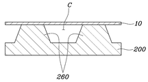
도 10 및 도 11에 도시된 바와 같이 유입 랜드돌기(260)는 제 1 탄성체 프레임(200)에 분리판(10) 방향으로 돌출되도록 형성되되, 그 단면의 폭이 돌출되는 방향으로 점점 좁아지는 것이 바람직하다. 이때 유입 랜드돌기(260)의 형상은 다양하게 변경되어 실시될 수 있을 것이다. 이렇게 유입 랜드돌기(260)의 단면 폭을 점점 좁아지게 형성하는 이유는 제 1 탄성체 프레임(200)과 분리판(10)의 적층 및 접합을 위하여 제 1 탄성체 프레임(200)과 분리판(10)을 압착하는 경우에 제 1 탄성체 프레임(200)이 압축에 의한 변형으로 채널(C)이 막히지 않도록 하기 위함이다.10 and 11, the
또한, 도 12 및 도 13과 같이 제 1 탄성체 프레임과 분리판을 압착하는 경우에 유입 랜드돌기의 형상을 유지시키면서 그 위치가 변경되는 것을 방지하기 위하여 분리판의 형상을 변경시킬 수 있다.In addition, as shown in FIGS. 12 and 13, when compressing the first elastic frame and the separation plate, the shape of the separation plate may be changed in order to prevent the position from being changed while maintaining the shape of the inflow land protrusion.
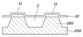
예를 들어 도 12에 도시된 바와 같이 분리판(10)은 유입 랜드돌기(260)가 접하는 영역에 유입 랜드돌기(260)의 단부 형상에 대응되는 인입홈(11)이 형성될 수 있다.For example, as illustrated in FIG. 12, the
또한, 도 13에 도시된 바와 같이 분리판(10)은 유입 랜드돌기(260)가 접하는 영역을 둘러싸는 가이드 돌기(12)가 형성될 수 있다.In addition, as shown in FIG. 13, the
본 발명을 첨부 도면과 전술된 바람직한 실시예를 참조하여 설명하였으나, 본 발명은 그에 한정되지 않으며, 후술되는 특허청구범위에 의해 한정된다. 따라서, 본 기술분야의 통상의 지식을 가진 자라면 후술되는 특허청구범위의 기술적 사상에서 벗어나지 않는 범위 내에서 본 발명을 다양하게 변형 및 수정할 수 있다.Although the present invention has been described with reference to the accompanying drawings and the preferred embodiments described above, the present invention is not limited thereto, and is limited by the claims below. Therefore, one of ordinary skill in the art can variously modify and modify the present invention without departing from the technical spirit of the claims to be described later.
100: 인서트
110: 막전극접합체(MEA)
120: 기체확산층(GDL)
200,300,400,500,610,620,710,720,810,820,910,920: 탄성체 프레임
210, 310, 410, 510: 반응면 관통홀
220, 322a, 421, 422: 유입매니폴드 관통홀
230, 322b, 431, 432: 배출매니폴드 관통홀
240: 단턱부
250: 연장홈부
260a, 321a, 450a: 유입 랜드돌기
260b, 321b, 450b: 배출 랜드돌기
H1 ~ H3: 융착부100: insert
110: membrane electrode assembly (MEA)
120: gas diffusion layer (GDL)
200,300,400,500,610,620,710,720,810,820,910,920: elastic frame
210, 310, 410, 510: through hole of reaction surface
220, 322a, 421, 422: inlet manifold through hole
230, 322b, 431, 432: exhaust manifold through hole
240: step
250: extended groove
260a, 321a, 450a: inflow land projection
260b, 321b, 450b: exhaust land projection
H1 ~ H3: Fusion part
Claims (17)
막전극접합체와, 그 양면에 배치되는 한 쌍의 기체확산층이 접합된 인서트와;
상기 인서트의 외곽영역에서 상기 인서트의 테두리 하면과 상면에 각각 배치되는 한 쌍의 시트형 탄성체 프레임이 상호 간에 열융착되어 일체로 형성되고, 상기 인서트가 배치되는 반응면 관통홀이 형성되며, 상기 반응면 관통홀의 외곽영역에는 반응가스 및 냉각수가 유입되는 복수의 유입매니폴드 관통홀이 형성되고, 타측에는 반응가스 및 냉각수가 배출되는 복수의 배출매니폴드 관통홀이 형성되며, 상기 복수의 유입매니폴드 관통홀 중 적어도 어느 하나 이상과 반응면 관통홀 사이 영역에는 반응가스 및 냉각수가 유동되는 유로를 형성하는 유입 랜드돌기가 형성되고, 상기 복수의 배출매니폴드 관통홀 중 적어도 어느 하나 이상과 반응면 관통홀 사이 영역에는 반응가스 및 냉각수가 유동되는 경로를 형성하는 배출 랜드돌기가 형성되는 탄성체 프레임을 포함하는 연료전지용 탄성체 셀 프레임.
A cell frame constituting a unit cell of a fuel cell,
A membrane electrode assembly and an insert in which a pair of gas diffusion layers disposed on both sides are bonded;
In the outer region of the insert, a pair of sheet-like elastic frames respectively disposed on the lower surface and the upper surface of the insert are heat-sealed to each other and integrally formed, and a reaction surface through-hole in which the insert is disposed is formed, and the reaction surface A plurality of inlet manifold through-holes through which reaction gas and cooling water are introduced are formed in an outer region of the through hole, and a plurality of outlet manifold through-holes through which reaction gas and cooling water are discharged are formed on the other side, and through the plurality of inlet manifolds. Inlet land protrusions forming a flow path through which reaction gas and cooling water flow are formed in a region between at least one of the holes and a reaction surface through hole, and at least one of the plurality of discharge manifold through holes and a reaction surface through hole An elastic cell frame for a fuel cell including an elastic body frame in which discharge land protrusions forming a path through which reaction gas and cooling water flow are formed.
상기 탄성체 프레임은
상기 인서트의 외곽영역에서 상기 인서트의 테두리 하면 및 측면을 둘러싸도록 배치되고, 상기 반응면 관통홀의 내주면에는 상기 인서트의 하면 및 측면을 감싸는 단턱부가 형성되며, 상기 복수의 유입매니폴드 관통홀 중 적어도 어느 하나 이상의 외곽영역과 상기 복수의 배출매니폴드 관통홀 중 적어도 어느 하나 이상의 외곽영역에는 상기 단턱부와 연통되는 안착홈부가 형성되는 제 1 탄성체 프레임과;
상기 인서트의 테두리 상면을 둘러싸도록 배치되면서, 상기 안착홈부에 대응되는 형상으로 연장부가 형성되어 상기 인서트의 테두리에서 상기 탄성체 프레임의 단턱부의 내주면과 안착홈부에 대면되는 제 2 탄성체 프레임으로 이루어지는 연료전지용 탄성체 셀 프레임.
The method according to claim 1,
The elastic frame
In the outer region of the insert is disposed to surround the lower surface and the side surface of the insert, the inner peripheral surface of the reaction surface through-hole is formed with a stepped portion surrounding the lower surface and side surface of the insert, at least any one of the plurality of inlet manifold through-holes A first elastic frame in which one or more outer regions and at least one outer region of the plurality of discharge manifold through holes are formed with seating grooves communicating with the stepped portions;
While being arranged to surround the upper surface of the rim of the insert, an extension is formed in a shape corresponding to the seating groove, and an elastic body for a fuel cell made of a second elastic frame facing the seating groove and the inner circumferential surface of the stepped portion of the elastic frame at the rim of the insert Cell frame.
상기 인서트, 제 1 탄성체 프레임 및 제 2 탄성체 프레임 사이에는,
상기 제 1 탄성체 프레임의 단턱부와 상기 인서트의 하면이 대면되어 열융착되는 제 1 융착부와;
상기 제 2 탄성체 프레임, 상기 인서트의 상면 및 안착홈부가 대면되어 열융착되는 제 2 융착부와;
상기 제 1 탄성체 프레임의 단턱부와 상기 인서트의 측면이 대면되어 열융착되는 제 3 융착부가 형성되는 것을 특징으로 하는 연료전지용 탄성체 셀 프레임.
The method according to claim 2,
Between the insert, the first elastic frame and the second elastic frame,
A first fusion part that is heat-sealed when the lower end of the first elastic frame and the lower surface of the insert face each other;
A second fusion part that is heat-sealed by facing the second elastic frame, the upper surface of the insert and the seating groove;
An elastic cell frame for a fuel cell, characterized in that a third fused portion is formed by heat-sealing a short side of the first elastic frame and a side surface of the insert.
상기 제 1 탄성체 프레임과 제 2 탄성체 프레임은 상호 간에 대면되는 영역이 서로 대응되는 경사면을 형성하는 것을 특징으로 하는 연료전지용 탄성체 셀 프레임.
The method according to claim 2,
The first elastic body frame and the second elastic body frame is an elastic cell frame for a fuel cell, characterized in that the regions facing each other form an inclined surface corresponding to each other.
상기 제 1 탄성체 프레임과 제 2 탄성체 프레임은 상호 간에 대면되는 영역이 서로 대응되는 요철구조로 형성되는 것을 특징으로 하는 연료전지용 탄성체 셀 프레임.
The method according to claim 2,
The first elastic frame and the second elastic frame is an elastic cell frame for a fuel cell, characterized in that the regions facing each other are formed with an uneven structure corresponding to each other.
상기 탄성체 프레임을 형성하는 한 쌍의 시트형 탄성체 프레임은 열가소성 탄성체(TPE)로 형성되는 것을 특징으로 하는 연료전지용 탄성체 셀 프레임.
The method according to claim 1,
A pair of sheet-shaped elastic frame forming the elastic frame is a fuel cell elastic cell frame, characterized in that formed of a thermoplastic elastomer (TPE).
상기 유입 랜드돌기 및 배출 랜드돌기는 단면의 폭이 돌출되는 방향으로 점점 좁아지는 것을 특징으로 하는 연료전지용 탄성체 셀 프레임.
The method according to claim 1,
The inflow land projection and the discharge land projection is an elastic cell frame for a fuel cell, characterized in that the width of the cross-section is gradually narrowed in the protruding direction.
막전극접합체의 양면에 각각 기체확산층을 접합하여 인서트를 준비하는 인서트 준비단계와;
반응가스 및 냉각수가 유동되는 경로를 형성하는 유입 랜드돌기 및 배출 랜드돌기가 형성된 한 쌍의 시트형 탄성체 프레임을 준비하는 탄성체 프레임 준비단계와;
상기 인서트를 사이에 두고 상기 한 쌍의 탄성체 프레임을 배치하는 배치단계와;
상기 한 쌍의 탄성체 프레임에 열을 가하면서 압착하여 상호 간을 열융착시켜서 일체로 형성하는 접합단계를 포함하는 연료전지용 탄성체 셀 프레임의 제조방법.
A method of manufacturing a cell frame constituting a unit cell of a fuel cell stack,
An insert preparation step of preparing an insert by bonding a gas diffusion layer to both surfaces of the membrane electrode assembly;
An elastic frame preparation step of preparing a pair of sheet-like elastic frames formed with inflow land projections and exhaust land projections forming a path through which reaction gas and cooling water flow;
An arrangement step of arranging the pair of elastic frames with the insert in between;
A method of manufacturing an elastic cell frame for a fuel cell, comprising a joining step of heat-sealing each other by pressing while applying heat to the pair of elastic frames.
상기 탄성체 프레임 준비단계에서 상기 탄성체 프레임은 열가소성 탄성체(TPE)를 시트의 형태로 성형하여 준비하는 것을 특징으로 하는 연료전지용 탄성체 셀 프레임의 제조방법.
The method according to claim 8,
In the step of preparing the elastic frame, the elastic frame is prepared by molding and preparing a thermoplastic elastomer (TPE) in the form of a sheet.
상기 접합단계는 상기 한 쌍의 탄성체 프레임 사이에 상기 인서트가 개재된 상태에서 상기 한 쌍의 탄성체 프레임이 사로 대면되는 영역 중 일부 또는 전부에 열을 가하면서 압착하여 한 쌍의 탄성체 프레임을 접합시키는 것을 특징으로 하는 연료전지용 탄성체 셀 프레임의 제조방법.
The method according to claim 8,
In the bonding step, bonding the pair of elastic frames by pressing while applying heat to some or all of the regions where the pair of elastic frames are faced with the insert interposed between the pair of elastic frames is interposed. Method of manufacturing an elastic cell frame for a fuel cell, characterized in that.
상기 접합단계에서 한 쌍의 탄성체 프레임에 가해지는 열은 상기 탄성체 프레임의 용융온도보다 높은 온도인 것을 특징으로 하는 연료전지용 탄성체 셀 프레임의 제조방법.
The method according to claim 8,
A method of manufacturing an elastic cell frame for a fuel cell, characterized in that the heat applied to the pair of elastic frames in the bonding step is higher than the melting temperature of the elastic frame.
상기 접합단계에서는 별도의 접착부재 없이 한 쌍의 탄성체 프레임이 상호 간에 열융착되면서 접합되는 것을 특징으로 하는 연료전지용 탄성체 셀 프레임의 제조방법.
The method according to claim 8,
In the bonding step, a method of manufacturing an elastic cell frame for a fuel cell, characterized in that a pair of elastic frames are joined while being heat-sealed to each other without a separate adhesive member.
상기 탄성체 셀 프레임의 양면에 배치되어 반응가스 및 냉각수의 유동을 유도하는 한 쌍의 분리판을 포함하는 연료전지용 단위 셀.
A membrane electrode assembly; In the outer region of the insert, a pair of sheet-like elastic frames respectively disposed on the lower surface and the upper surface of the insert are heat-sealed to each other and integrally formed, and a reaction surface through-hole in which the insert is disposed is formed, and the reaction surface A plurality of inlet manifold through-holes through which reaction gas and cooling water are introduced are formed in an outer region of the through hole, and a plurality of outlet manifold through-holes through which reaction gas and cooling water are discharged are formed on the other side, and through the plurality of inlet manifolds. Inlet land protrusions forming a flow path through which reaction gas and cooling water flow are formed in a region between at least one of the holes and a reaction surface through hole, and at least one of the plurality of discharge manifold through holes and a reaction surface through hole An elastic cell frame including an elastic body frame in which discharge land protrusions forming a path through which reaction gas and cooling water flow are formed;
A unit cell for a fuel cell including a pair of separator plates disposed on both sides of the elastic cell frame to induce the flow of reaction gas and cooling water.
상기 탄성체 셀 프레임과 분리판은 상기 탄성체 셀 프레임이 열융착되어 접합되는 것을 특징으로 하는 연료전지용 단위 셀.
The method according to claim 13,
The elastic cell frame and the separation plate are unit cells for a fuel cell, characterized in that the elastic cell frame is heat-sealed and joined.
상기 유입 랜드돌기 및 배출 랜드돌기가 상기 분리판에 접하면서 반응가스 및 냉각수가 유동되는 채널이 형성되는 것을 특징으로 하는 연료전지용 단위 셀.
The method according to claim 13,
A unit cell for a fuel cell, characterized in that a channel through which reaction gas and cooling water flows is formed while the inflow land protrusion and the exhaust land protrusion contact the separation plate.
상기 분리판은 상기 탄성체 셀 프레임의 유입 랜드돌기 및 배출 랜드돌기가 접하는 영역에 상기 유입 랜드돌기 및 배출 랜드돌기의 단부 형상에 대응되는 인입홈이 형성되는 것을 특징으로 하는 연료전지용 단위 셀.
The method according to claim 15,
The separator is a unit cell for a fuel cell, characterized in that an inlet groove corresponding to an end shape of the inlet land protrusion and the outlet land protrusion is formed in a region in contact with the inlet land protrusion and the outlet land protrusion of the elastic cell frame.
상기 분리판은 상기 탄성체 셀 프레임의 유입 랜드돌기 및 배출 랜드돌기가 접하는 영역을 둘러싸는 가이드 돌기가 형성되는 것을 특징으로 하는 연료전지용 단위 셀.
The method according to claim 15,
The separator is a unit cell for a fuel cell, characterized in that a guide protrusion is formed surrounding an area in contact with the inflow and outgoing land protrusions of the elastic cell frame.
Priority Applications (4)
| Application Number | Priority Date | Filing Date | Title |
|---|---|---|---|
| KR1020180158663A KR20200070944A (en) | 2018-12-10 | 2018-12-10 | Elastomer cell frame for fuel cell and manufacturing method thereof and unit cell comprising thereof |
| US16/548,614 US11050074B2 (en) | 2018-12-10 | 2019-08-22 | Elastomeric cell frame for fuel cell and manufacturing method thereof, and unit cell using the same |
| CN201910881565.8A CN111293329B (en) | 2018-12-10 | 2019-09-18 | Elastic cell frame of fuel cell, manufacturing method thereof and unit cell using the same |
| DE102019215468.9A DE102019215468A1 (en) | 2018-12-10 | 2019-10-09 | Elastomer cell frame for fuel cell and manufacturing process therefor as well as unit cell with it |
Applications Claiming Priority (1)
| Application Number | Priority Date | Filing Date | Title |
|---|---|---|---|
| KR1020180158663A KR20200070944A (en) | 2018-12-10 | 2018-12-10 | Elastomer cell frame for fuel cell and manufacturing method thereof and unit cell comprising thereof |
Publications (1)
| Publication Number | Publication Date |
|---|---|
| KR20200070944A true KR20200070944A (en) | 2020-06-18 |
Family
ID=70776537
Family Applications (1)
| Application Number | Title | Priority Date | Filing Date |
|---|---|---|---|
| KR1020180158663A KR20200070944A (en) | 2018-12-10 | 2018-12-10 | Elastomer cell frame for fuel cell and manufacturing method thereof and unit cell comprising thereof |
Country Status (4)
| Country | Link |
|---|---|
| US (1) | US11050074B2 (en) |
| KR (1) | KR20200070944A (en) |
| CN (1) | CN111293329B (en) |
| DE (1) | DE102019215468A1 (en) |
Families Citing this family (5)
| Publication number | Priority date | Publication date | Assignee | Title |
|---|---|---|---|---|
| JP7310786B2 (en) * | 2020-11-20 | 2023-07-19 | トヨタ自動車株式会社 | Fuel cell |
| JP7456373B2 (en) * | 2020-12-25 | 2024-03-27 | トヨタ自動車株式会社 | Fuel cell and its manufacturing method |
| EP4181245A1 (en) * | 2021-11-12 | 2023-05-17 | AVL List GmbH | Frame device for a fuel stack and fuel cell device comprising the same |
| DE102022208819A1 (en) | 2022-08-25 | 2024-03-07 | Robert Bosch Gesellschaft mit beschränkter Haftung | Electrochemical cell, fuel cell stack and method for producing an electrochemical cell |
| CN116014200A (en) * | 2022-12-09 | 2023-04-25 | 大连海事大学 | Positive and negative electrode frame integrated flow field structure of high-power density flow battery |
Citations (2)
| Publication number | Priority date | Publication date | Assignee | Title |
|---|---|---|---|---|
| JP2017212126A (en) | 2016-05-26 | 2017-11-30 | トヨタ自動車株式会社 | Fuel cell |
| KR20180011716A (en) | 2016-07-25 | 2018-02-02 | 도요타지도샤가부시키가이샤 | Fuel-cell unit cell and manufacturing method therefor |
Family Cites Families (13)
| Publication number | Priority date | Publication date | Assignee | Title |
|---|---|---|---|---|
| JP3940920B2 (en) * | 2000-11-21 | 2007-07-04 | Nok株式会社 | Fuel cell components |
| EP1633010B1 (en) * | 2003-05-12 | 2016-04-27 | Mitsubishi Materials Corporation | Composite porous body, member for gas diffusion layer, cell member, and their manufacturing methods |
| KR100801430B1 (en) * | 2006-10-16 | 2008-02-05 | 현대하이스코 주식회사 | Seperator for fuel cell, fuel cell system having the sames and fuel cell stack |
| JP4719771B2 (en) * | 2007-06-11 | 2011-07-06 | パナソニック株式会社 | Electrode-membrane-frame assembly for fuel cell and manufacturing method thereof, and polymer electrolyte fuel cell and manufacturing method thereof |
| DE102009010794A1 (en) * | 2009-02-27 | 2010-09-02 | Li-Tec Battery Gmbh | Galvanic cell with frame and method for its production |
| JP5660256B1 (en) * | 2013-04-18 | 2015-01-28 | パナソニックIpマネジメント株式会社 | Solid polymer electrolyte fuel cell |
| JP2015113984A (en) | 2013-12-09 | 2015-06-22 | 株式会社知的未来 | Leg part environment regulation device |
| KR101620155B1 (en) * | 2014-01-22 | 2016-05-12 | 현대자동차주식회사 | Fuel cell and manufacturing method thereof |
| JP6534250B2 (en) | 2014-09-03 | 2019-06-26 | 保土谷化学工業株式会社 | Host material for delaying phosphor, organic light emitting device and compound |
| JP6237675B2 (en) * | 2015-03-03 | 2017-11-29 | トヨタ自動車株式会社 | FUEL CELL SINGLE CELL AND METHOD FOR PRODUCING FUEL CELL SINGLE CELL |
| JP6547731B2 (en) * | 2016-12-13 | 2019-07-24 | トヨタ自動車株式会社 | Fuel cell stack |
| KR20180070777A (en) * | 2016-12-16 | 2018-06-27 | 현대자동차주식회사 | Cell frame for fuelcell |
| JP6783695B2 (en) * | 2017-04-07 | 2020-11-11 | トヨタ自動車株式会社 | Manufacturing method of fuel cell single cell |
-
2018
- 2018-12-10 KR KR1020180158663A patent/KR20200070944A/en not_active Application Discontinuation
-
2019
- 2019-08-22 US US16/548,614 patent/US11050074B2/en active Active
- 2019-09-18 CN CN201910881565.8A patent/CN111293329B/en active Active
- 2019-10-09 DE DE102019215468.9A patent/DE102019215468A1/en active Pending
Patent Citations (2)
| Publication number | Priority date | Publication date | Assignee | Title |
|---|---|---|---|---|
| JP2017212126A (en) | 2016-05-26 | 2017-11-30 | トヨタ自動車株式会社 | Fuel cell |
| KR20180011716A (en) | 2016-07-25 | 2018-02-02 | 도요타지도샤가부시키가이샤 | Fuel-cell unit cell and manufacturing method therefor |
Also Published As
| Publication number | Publication date |
|---|---|
| DE102019215468A1 (en) | 2020-06-10 |
| CN111293329B (en) | 2024-03-15 |
| US20200185747A1 (en) | 2020-06-11 |
| CN111293329A (en) | 2020-06-16 |
| US11050074B2 (en) | 2021-06-29 |
Similar Documents
| Publication | Publication Date | Title |
|---|---|---|
| US10811715B2 (en) | Fuel-cell unit cell and manufacturing method therefor | |
| KR20200070944A (en) | Elastomer cell frame for fuel cell and manufacturing method thereof and unit cell comprising thereof | |
| JP5615875B2 (en) | Electrolyte membrane / electrode structure with resin frame for fuel cells | |
| JP5855442B2 (en) | Manufacturing method of electrolyte membrane / electrode structure with resin frame for fuel cell | |
| CN113611888B (en) | Fuel cell | |
| JP4852840B2 (en) | Separator | |
| JP7257851B2 (en) | Elastic cell frame for fuel cell, manufacturing method thereof, and unit cell using same | |
| KR20200072198A (en) | Elastomer cell frame for fuel cell and manufacturing method thereof and unit cell comprising thereof | |
| KR20200132294A (en) | Elastomer cell frame for fuel cell and Manufacturing method thereof and Fuel cell stack comprising thereof | |
| JP4880995B2 (en) | Fuel cell module and fuel cell stack | |
| KR20210015384A (en) | Elastomeric cell frame for fuel cell and manufacturing method thereof and unit cell comprising thereof | |
| CN112751054A (en) | Unit cell of fuel cell | |
| CN112993307A (en) | Elastomeric cell frame for fuel cell | |
| US20040159543A1 (en) | Electrochemical cell plate with integral seals | |
| JP6241594B2 (en) | Membrane electrode assembly with frame, single fuel cell and fuel cell stack | |
| JP6229874B2 (en) | Membrane electrode assembly with frame, single fuel cell and fuel cell stack | |
| KR20220008627A (en) | Elastomeric cell frame for fuel cell and Unit cell and Fuel cell stack comprising the same | |
| JP7236913B2 (en) | Fuel cell separator assembly and fuel cell stack including the same | |
| JP4172350B2 (en) | Fuel cell separator | |
| KR20210076468A (en) | Elastomeric cell frame for fuel cell and manufacturing method thereof and unit cell comprising thereof | |
| JP2021018963A (en) | Manufacturing method of fuel battery single cell | |
| JP2017117722A (en) | Gasket for fuel cell and manufacturing method therefor | |
| JP2005228500A (en) | Manufacturing method of fuel cell stack |
Legal Events
| Date | Code | Title | Description |
|---|---|---|---|
| A201 | Request for examination | ||
| E902 | Notification of reason for refusal |