KR20110088514A - Electroactive polymer transducers for tactile feedback devices - Google Patents
Electroactive polymer transducers for tactile feedback devices Download PDFInfo
- Publication number
- KR20110088514A KR20110088514A KR1020117010172A KR20117010172A KR20110088514A KR 20110088514 A KR20110088514 A KR 20110088514A KR 1020117010172 A KR1020117010172 A KR 1020117010172A KR 20117010172 A KR20117010172 A KR 20117010172A KR 20110088514 A KR20110088514 A KR 20110088514A
- Authority
- KR
- South Korea
- Prior art keywords
- electroactive polymer
- transducer
- film
- actuator
- inertial
- Prior art date
Links
- 229920001746 electroactive polymer Polymers 0.000 title claims abstract description 215
- 238000000034 method Methods 0.000 claims abstract description 44
- 230000000694 effects Effects 0.000 claims abstract description 21
- 229920000642 polymer Polymers 0.000 claims description 38
- 238000006073 displacement reaction Methods 0.000 claims description 34
- 230000033001 locomotion Effects 0.000 claims description 33
- 229920002595 Dielectric elastomer Polymers 0.000 claims description 13
- 238000001914 filtration Methods 0.000 claims description 10
- 230000005236 sound signal Effects 0.000 claims description 9
- 230000004913 activation Effects 0.000 claims description 8
- 229920006254 polymer film Polymers 0.000 claims description 8
- 230000001131 transforming effect Effects 0.000 claims 1
- 230000001953 sensory effect Effects 0.000 abstract description 23
- 239000010408 film Substances 0.000 description 137
- 239000010410 layer Substances 0.000 description 95
- 239000000463 material Substances 0.000 description 31
- 230000004044 response Effects 0.000 description 24
- 239000012528 membrane Substances 0.000 description 17
- 230000008878 coupling Effects 0.000 description 14
- 238000010168 coupling process Methods 0.000 description 14
- 238000005859 coupling reaction Methods 0.000 description 14
- 238000013461 design Methods 0.000 description 14
- 239000003989 dielectric material Substances 0.000 description 12
- 230000008859 change Effects 0.000 description 10
- 230000009471 action Effects 0.000 description 9
- 230000006870 function Effects 0.000 description 9
- 238000004519 manufacturing process Methods 0.000 description 9
- 230000004048 modification Effects 0.000 description 9
- 238000012986 modification Methods 0.000 description 9
- 241000699666 Mus <mouse, genus> Species 0.000 description 8
- 230000005684 electric field Effects 0.000 description 8
- 239000007772 electrode material Substances 0.000 description 8
- 230000001976 improved effect Effects 0.000 description 8
- 230000008901 benefit Effects 0.000 description 7
- 230000035807 sensation Effects 0.000 description 7
- 230000004888 barrier function Effects 0.000 description 6
- 229920001971 elastomer Polymers 0.000 description 6
- OKTJSMMVPCPJKN-UHFFFAOYSA-N Carbon Chemical compound [C] OKTJSMMVPCPJKN-UHFFFAOYSA-N 0.000 description 5
- 238000003491 array Methods 0.000 description 5
- 230000000712 assembly Effects 0.000 description 5
- 238000000429 assembly Methods 0.000 description 5
- 238000006243 chemical reaction Methods 0.000 description 5
- 230000003213 activating effect Effects 0.000 description 4
- 239000012790 adhesive layer Substances 0.000 description 4
- 239000004020 conductor Substances 0.000 description 4
- 239000000806 elastomer Substances 0.000 description 4
- 230000007613 environmental effect Effects 0.000 description 4
- 229910052751 metal Inorganic materials 0.000 description 4
- 239000002184 metal Substances 0.000 description 4
- 239000002245 particle Substances 0.000 description 4
- 230000001681 protective effect Effects 0.000 description 4
- 229910001285 shape-memory alloy Inorganic materials 0.000 description 4
- 230000000007 visual effect Effects 0.000 description 4
- 229910052799 carbon Inorganic materials 0.000 description 3
- 230000008602 contraction Effects 0.000 description 3
- 238000010586 diagram Methods 0.000 description 3
- 238000005553 drilling Methods 0.000 description 3
- 239000011888 foil Substances 0.000 description 3
- 239000000499 gel Substances 0.000 description 3
- 230000003993 interaction Effects 0.000 description 3
- 230000008961 swelling Effects 0.000 description 3
- XEEYBQQBJWHFJM-UHFFFAOYSA-N Iron Chemical compound [Fe] XEEYBQQBJWHFJM-UHFFFAOYSA-N 0.000 description 2
- PXHVJJICTQNCMI-UHFFFAOYSA-N Nickel Chemical compound [Ni] PXHVJJICTQNCMI-UHFFFAOYSA-N 0.000 description 2
- PPBRXRYQALVLMV-UHFFFAOYSA-N Styrene Chemical compound C=CC1=CC=CC=C1 PPBRXRYQALVLMV-UHFFFAOYSA-N 0.000 description 2
- 238000013459 approach Methods 0.000 description 2
- 230000002457 bidirectional effect Effects 0.000 description 2
- 230000015572 biosynthetic process Effects 0.000 description 2
- 230000006835 compression Effects 0.000 description 2
- 238000007906 compression Methods 0.000 description 2
- 229920001577 copolymer Polymers 0.000 description 2
- 238000005516 engineering process Methods 0.000 description 2
- 239000006260 foam Substances 0.000 description 2
- 239000004519 grease Substances 0.000 description 2
- 230000001771 impaired effect Effects 0.000 description 2
- 230000006872 improvement Effects 0.000 description 2
- 238000007373 indentation Methods 0.000 description 2
- 239000004973 liquid crystal related substance Substances 0.000 description 2
- 239000011159 matrix material Substances 0.000 description 2
- 230000007935 neutral effect Effects 0.000 description 2
- 230000002093 peripheral effect Effects 0.000 description 2
- 229920001690 polydopamine Polymers 0.000 description 2
- 229920001296 polysiloxane Polymers 0.000 description 2
- 238000004382 potting Methods 0.000 description 2
- 238000003825 pressing Methods 0.000 description 2
- 230000008569 process Effects 0.000 description 2
- 230000009467 reduction Effects 0.000 description 2
- 230000002441 reversible effect Effects 0.000 description 2
- 239000005060 rubber Substances 0.000 description 2
- 229910052710 silicon Inorganic materials 0.000 description 2
- 239000010703 silicon Substances 0.000 description 2
- 238000012546 transfer Methods 0.000 description 2
- 230000001960 triggered effect Effects 0.000 description 2
- WBTMFEPLVQOWFI-UHFFFAOYSA-N 1,3-dichloro-5-(2,5-dichlorophenyl)benzene Chemical compound ClC1=CC=C(Cl)C(C=2C=C(Cl)C=C(Cl)C=2)=C1 WBTMFEPLVQOWFI-UHFFFAOYSA-N 0.000 description 1
- 229920004439 Aclar® Polymers 0.000 description 1
- NIXOWILDQLNWCW-UHFFFAOYSA-M Acrylate Chemical compound [O-]C(=O)C=C NIXOWILDQLNWCW-UHFFFAOYSA-M 0.000 description 1
- 229910001369 Brass Inorganic materials 0.000 description 1
- 229920000049 Carbon (fiber) Polymers 0.000 description 1
- 239000004215 Carbon black (E152) Substances 0.000 description 1
- VYZAMTAEIAYCRO-UHFFFAOYSA-N Chromium Chemical compound [Cr] VYZAMTAEIAYCRO-UHFFFAOYSA-N 0.000 description 1
- RYGMFSIKBFXOCR-UHFFFAOYSA-N Copper Chemical compound [Cu] RYGMFSIKBFXOCR-UHFFFAOYSA-N 0.000 description 1
- JOYRKODLDBILNP-UHFFFAOYSA-N Ethyl urethane Chemical compound CCOC(N)=O JOYRKODLDBILNP-UHFFFAOYSA-N 0.000 description 1
- YCKRFDGAMUMZLT-UHFFFAOYSA-N Fluorine atom Chemical compound [F] YCKRFDGAMUMZLT-UHFFFAOYSA-N 0.000 description 1
- 241000699670 Mus sp. Species 0.000 description 1
- 229920001328 Polyvinylidene chloride Polymers 0.000 description 1
- BQCADISMDOOEFD-UHFFFAOYSA-N Silver Chemical compound [Ag] BQCADISMDOOEFD-UHFFFAOYSA-N 0.000 description 1
- 230000001133 acceleration Effects 0.000 description 1
- 150000001252 acrylic acid derivatives Chemical class 0.000 description 1
- NIXOWILDQLNWCW-UHFFFAOYSA-N acrylic acid group Chemical group C(C=C)(=O)O NIXOWILDQLNWCW-UHFFFAOYSA-N 0.000 description 1
- 239000000654 additive Substances 0.000 description 1
- 239000000853 adhesive Substances 0.000 description 1
- 238000004026 adhesive bonding Methods 0.000 description 1
- 230000001070 adhesive effect Effects 0.000 description 1
- 229910052782 aluminium Inorganic materials 0.000 description 1
- XAGFODPZIPBFFR-UHFFFAOYSA-N aluminium Chemical compound [Al] XAGFODPZIPBFFR-UHFFFAOYSA-N 0.000 description 1
- 239000010951 brass Substances 0.000 description 1
- 239000004917 carbon fiber Substances 0.000 description 1
- 229910021393 carbon nanotube Inorganic materials 0.000 description 1
- 239000002041 carbon nanotube Substances 0.000 description 1
- 230000015556 catabolic process Effects 0.000 description 1
- 229910052804 chromium Inorganic materials 0.000 description 1
- 239000011651 chromium Substances 0.000 description 1
- 238000004040 coloring Methods 0.000 description 1
- 239000002131 composite material Substances 0.000 description 1
- 238000009833 condensation Methods 0.000 description 1
- 230000005494 condensation Effects 0.000 description 1
- 239000000470 constituent Substances 0.000 description 1
- 238000010276 construction Methods 0.000 description 1
- 239000000356 contaminant Substances 0.000 description 1
- 229910052802 copper Inorganic materials 0.000 description 1
- 239000010949 copper Substances 0.000 description 1
- 238000004132 cross linking Methods 0.000 description 1
- 238000005520 cutting process Methods 0.000 description 1
- 125000004122 cyclic group Chemical group 0.000 description 1
- 238000013479 data entry Methods 0.000 description 1
- 230000026058 directional locomotion Effects 0.000 description 1
- 238000009826 distribution Methods 0.000 description 1
- 230000005489 elastic deformation Effects 0.000 description 1
- 239000013536 elastomeric material Substances 0.000 description 1
- 238000009429 electrical wiring Methods 0.000 description 1
- 230000008713 feedback mechanism Effects 0.000 description 1
- 238000010304 firing Methods 0.000 description 1
- 239000012530 fluid Substances 0.000 description 1
- 239000011737 fluorine Substances 0.000 description 1
- 229910052731 fluorine Inorganic materials 0.000 description 1
- 239000011521 glass Substances 0.000 description 1
- 229910021389 graphene Inorganic materials 0.000 description 1
- 238000003306 harvesting Methods 0.000 description 1
- 229930195733 hydrocarbon Natural products 0.000 description 1
- 150000002430 hydrocarbons Chemical class 0.000 description 1
- 238000002513 implantation Methods 0.000 description 1
- 230000001939 inductive effect Effects 0.000 description 1
- 229910052742 iron Inorganic materials 0.000 description 1
- 238000003475 lamination Methods 0.000 description 1
- 230000000670 limiting effect Effects 0.000 description 1
- 238000005259 measurement Methods 0.000 description 1
- 230000007246 mechanism Effects 0.000 description 1
- 239000002905 metal composite material Substances 0.000 description 1
- 229910001092 metal group alloy Inorganic materials 0.000 description 1
- 150000002739 metals Chemical class 0.000 description 1
- VNWKTOKETHGBQD-UHFFFAOYSA-N methane Chemical compound C VNWKTOKETHGBQD-UHFFFAOYSA-N 0.000 description 1
- 239000000203 mixture Substances 0.000 description 1
- 239000000178 monomer Substances 0.000 description 1
- 238000000465 moulding Methods 0.000 description 1
- 239000002070 nanowire Substances 0.000 description 1
- 229910052759 nickel Inorganic materials 0.000 description 1
- 239000012811 non-conductive material Substances 0.000 description 1
- 230000003287 optical effect Effects 0.000 description 1
- 230000010355 oscillation Effects 0.000 description 1
- 239000005022 packaging material Substances 0.000 description 1
- 230000036961 partial effect Effects 0.000 description 1
- 230000000149 penetrating effect Effects 0.000 description 1
- 230000000704 physical effect Effects 0.000 description 1
- 239000004033 plastic Substances 0.000 description 1
- 229920003023 plastic Polymers 0.000 description 1
- 239000005023 polychlorotrifluoroethylene (PCTFE) polymer Substances 0.000 description 1
- 229920000728 polyester Polymers 0.000 description 1
- 229920000098 polyolefin Polymers 0.000 description 1
- 229920002635 polyurethane Polymers 0.000 description 1
- 239000004814 polyurethane Substances 0.000 description 1
- 239000005033 polyvinylidene chloride Substances 0.000 description 1
- 230000010349 pulsation Effects 0.000 description 1
- 238000004080 punching Methods 0.000 description 1
- 230000002829 reductive effect Effects 0.000 description 1
- 230000003014 reinforcing effect Effects 0.000 description 1
- 239000011347 resin Substances 0.000 description 1
- 229920005989 resin Polymers 0.000 description 1
- 238000007789 sealing Methods 0.000 description 1
- 230000035939 shock Effects 0.000 description 1
- 229920002379 silicone rubber Polymers 0.000 description 1
- 239000004945 silicone rubber Substances 0.000 description 1
- 229910052709 silver Inorganic materials 0.000 description 1
- 239000004332 silver Substances 0.000 description 1
- 238000004513 sizing Methods 0.000 description 1
- 238000001228 spectrum Methods 0.000 description 1
- 239000003351 stiffener Substances 0.000 description 1
- 230000000638 stimulation Effects 0.000 description 1
- 239000000126 substance Substances 0.000 description 1
- 239000000725 suspension Substances 0.000 description 1
- 230000001360 synchronised effect Effects 0.000 description 1
- 229920002725 thermoplastic elastomer Polymers 0.000 description 1
- 239000010409 thin film Substances 0.000 description 1
- WFKWXMTUELFFGS-UHFFFAOYSA-N tungsten Chemical compound [W] WFKWXMTUELFFGS-UHFFFAOYSA-N 0.000 description 1
- 229910052721 tungsten Inorganic materials 0.000 description 1
- 239000010937 tungsten Substances 0.000 description 1
- 230000037303 wrinkles Effects 0.000 description 1
Images


Classifications
-
- G—PHYSICS
- G06—COMPUTING; CALCULATING OR COUNTING
- G06F—ELECTRIC DIGITAL DATA PROCESSING
- G06F3/00—Input arrangements for transferring data to be processed into a form capable of being handled by the computer; Output arrangements for transferring data from processing unit to output unit, e.g. interface arrangements
- G06F3/01—Input arrangements or combined input and output arrangements for interaction between user and computer
- G06F3/016—Input arrangements with force or tactile feedback as computer generated output to the user
-
- B—PERFORMING OPERATIONS; TRANSPORTING
- B06—GENERATING OR TRANSMITTING MECHANICAL VIBRATIONS IN GENERAL
- B06B—METHODS OR APPARATUS FOR GENERATING OR TRANSMITTING MECHANICAL VIBRATIONS OF INFRASONIC, SONIC, OR ULTRASONIC FREQUENCY, e.g. FOR PERFORMING MECHANICAL WORK IN GENERAL
- B06B1/00—Methods or apparatus for generating mechanical vibrations of infrasonic, sonic, or ultrasonic frequency
- B06B1/02—Methods or apparatus for generating mechanical vibrations of infrasonic, sonic, or ultrasonic frequency making use of electrical energy
- B06B1/06—Methods or apparatus for generating mechanical vibrations of infrasonic, sonic, or ultrasonic frequency making use of electrical energy operating with piezoelectric effect or with electrostriction
- B06B1/0688—Methods or apparatus for generating mechanical vibrations of infrasonic, sonic, or ultrasonic frequency making use of electrical energy operating with piezoelectric effect or with electrostriction with foil-type piezoelectric elements, e.g. PVDF
-
- H—ELECTRICITY
- H02—GENERATION; CONVERSION OR DISTRIBUTION OF ELECTRIC POWER
- H02N—ELECTRIC MACHINES NOT OTHERWISE PROVIDED FOR
- H02N2/00—Electric machines in general using piezoelectric effect, electrostriction or magnetostriction
- H02N2/02—Electric machines in general using piezoelectric effect, electrostriction or magnetostriction producing linear motion, e.g. actuators; Linear positioners ; Linear motors
-
- H—ELECTRICITY
- H10—SEMICONDUCTOR DEVICES; ELECTRIC SOLID-STATE DEVICES NOT OTHERWISE PROVIDED FOR
- H10N—ELECTRIC SOLID-STATE DEVICES NOT OTHERWISE PROVIDED FOR
- H10N30/00—Piezoelectric or electrostrictive devices
- H10N30/01—Manufacture or treatment
- H10N30/06—Forming electrodes or interconnections, e.g. leads or terminals
- H10N30/063—Forming interconnections, e.g. connection electrodes of multilayered piezoelectric or electrostrictive parts
-
- H—ELECTRICITY
- H10—SEMICONDUCTOR DEVICES; ELECTRIC SOLID-STATE DEVICES NOT OTHERWISE PROVIDED FOR
- H10N—ELECTRIC SOLID-STATE DEVICES NOT OTHERWISE PROVIDED FOR
- H10N30/00—Piezoelectric or electrostrictive devices
- H10N30/20—Piezoelectric or electrostrictive devices with electrical input and mechanical output, e.g. functioning as actuators or vibrators
- H10N30/206—Piezoelectric or electrostrictive devices with electrical input and mechanical output, e.g. functioning as actuators or vibrators using only longitudinal or thickness displacement, e.g. d33 or d31 type devices
-
- H—ELECTRICITY
- H10—SEMICONDUCTOR DEVICES; ELECTRIC SOLID-STATE DEVICES NOT OTHERWISE PROVIDED FOR
- H10N—ELECTRIC SOLID-STATE DEVICES NOT OTHERWISE PROVIDED FOR
- H10N30/00—Piezoelectric or electrostrictive devices
- H10N30/50—Piezoelectric or electrostrictive devices having a stacked or multilayer structure
-
- H—ELECTRICITY
- H10—SEMICONDUCTOR DEVICES; ELECTRIC SOLID-STATE DEVICES NOT OTHERWISE PROVIDED FOR
- H10N—ELECTRIC SOLID-STATE DEVICES NOT OTHERWISE PROVIDED FOR
- H10N30/00—Piezoelectric or electrostrictive devices
- H10N30/80—Constructional details
- H10N30/85—Piezoelectric or electrostrictive active materials
- H10N30/857—Macromolecular compositions
-
- H—ELECTRICITY
- H10—SEMICONDUCTOR DEVICES; ELECTRIC SOLID-STATE DEVICES NOT OTHERWISE PROVIDED FOR
- H10N—ELECTRIC SOLID-STATE DEVICES NOT OTHERWISE PROVIDED FOR
- H10N30/00—Piezoelectric or electrostrictive devices
- H10N30/80—Constructional details
- H10N30/87—Electrodes or interconnections, e.g. leads or terminals
- H10N30/872—Connection electrodes of multilayer piezoelectric or electrostrictive devices, e.g. external electrodes
- H10N30/874—Connection electrodes of multilayer piezoelectric or electrostrictive devices, e.g. external electrodes embedded within piezoelectric or electrostrictive material, e.g. via connections
Abstract
분리 발생되는 청각 신호에 의해 발생되는 음향과 동시에 사용자 인터페이스 장치 내에서 햅틱 효과를 생성하는 전기활성 트랜스듀서 및 방법과, 사용자 인터페이스 장치 내에서의 감각 피드백 용도를 위한 전기활성 중합체 트랜스듀서가 개시된다.Electroactive transducers and methods for generating haptic effects in a user interface device simultaneously with sound generated by a separately generated auditory signal, and electroactive polymer transducers for sensory feedback applications in a user interface device are disclosed.
Description
관련 출원Related application
본 출원은 발명의 명칭이 "ELECTRO ACTIVE POLYMER TRANSDUCERS FOR HAPTIC FEEDBACK"인, 2008년 11월 4일자로 출원된 미국 가출원 제61/111,316호 및 발명의 명칭이 "FILTER SOUND DRIVE WAVEFORM FOR EPAM HAPTICS AND EPAM ACTUATION PASSIVE FILM COUPLING"인 2008년 11월 4일자로 출원된 미국 가출원 제61/111,319호의 정규 출원이고, 이의 전문은 본원에 참고로 포함된다.This application is directed to US Provisional Application No. 61 / 111,316, filed Nov. 4, 2008, entitled "ELECTRO ACTIVE POLYMER TRANSDUCERS FOR HAPTIC FEEDBACK," and entitled "FILTER SOUND DRIVE WAVEFORM FOR EPAM HAPTICS AND EPAM ACTUATION." PASSIVE FILM COUPLING "is a regular application of US Provisional Application No. 61 / 111,319, filed November 4, 2008, the entirety of which is incorporated herein by reference.
발명의 분야Field of invention
본 발명은 감각 피드백을 제공하기 위한 전기활성 중합체 트랜스듀서의 사용에 관한 것이다.The present invention relates to the use of electroactive polymer transducers to provide sensory feedback.
오늘날 사용되는 매우 다양한 장치는 전기 에너지를 기계적 에너지로 변환시키기 위한 여러 종류의 액츄에이터에 의존한다. 역으로, 많은 전력 발생 장치가 기계 작용을 전기 에너지로 변환시킴으로써 작동한다. 이러한 방식으로 기계적 에너지를 수확하기 위해 채용되면, 동일한 유형의 액츄에이터는 발전기로 불릴 수 있다. 유사하게, 구조물이 진동 또는 압력과 같은 물리적 자극을 측정 목적으로 전기 신호로 변환시키도록 채용될 때, 이는 센서로서 기술될 수 있다. 또한, "트랜스듀서"라는 용어는 장치들 중 임의의 하나를 총칭하도록 사용될 수 있다.A wide variety of devices in use today rely on several types of actuators for converting electrical energy into mechanical energy. Conversely, many power generating devices work by converting mechanical action into electrical energy. When employed to harvest mechanical energy in this manner, actuators of the same type can be called generators. Similarly, when a structure is employed to convert a physical stimulus, such as vibration or pressure, into an electrical signal for measurement purposes, it can be described as a sensor. The term "transducer" may also be used to generically refer to any one of the devices.
다수의 설계 고려 사항이 트랜스듀서의 제작을 위해, "전기활성 중합체"(EAP)로도 불리는, 개선된 유전성 엘라스토머 물질의 선택 및 사용을 선호한다. 이러한 고려 사항은 전위력, 전력 밀도, 전력 변환/소비, 크기, 중량, 비용, 응답 시간, 듀티 사이클, 서비스 요건, 환경적 충격 등을 포함한다. 이와 같이, 많은 용도에서, EAP 기술은 압전 장치, 형상 기억 합금(SMA) 및 모터 및 솔레노이드와 같은 전자기 장치에 대한 이상적인 대체물을 제공한다.Many design considerations favor the selection and use of improved dielectric elastomeric materials, also referred to as "electroactive polymers" (EAPs), for the fabrication of transducers. These considerations include potential power, power density, power conversion / consumption, size, weight, cost, response time, duty cycle, service requirements, and environmental impact. As such, in many applications, EAP technology provides an ideal substitute for piezoelectric devices, shape memory alloys (SMA) and electromagnetic devices such as motors and solenoids.
EAP 장치 및 그의 용도의 예는 미국 특허 제7,394,282호; 제7,378,783호; 제7,368,862호; 제7,362,032호; 제7,320,457호; 제7,259,503호; 제7,233,097호; 제7,224,106호; 제7,211,937호; 제7,199,501호; 제7,166,953호; 제7,064,472호; 제7,062,055호; 제7,052,594호; 제7,049,732호; 제7,034,432호; 제6,940,221호; 제6,911,764호; 제6,891,317호; 제6,882,086호; 제6,876,135호; 제6,812,624호; 제6,809,462호; 제6,806,621호; 제6,781,284호; 제6,768,246호; 제6,707,236호; 제6,664,718호; 제6,628,040호; 제6,586,859호; 제6,583,533호; 제6,545,384호; 제6,543,110호; 제6,376,971호 및 제6,343,129호; 및 미국 특허 출원 공개 제2008/0157631호; 제2008/0116764호; 제2008/0022517호; 제2007/0230222호; 제2007/0200468호; 제2007/0200467호; 제2007/0200466호; 제2007/0200457호; 제2007/0200454호; 제2007/0200453호; 제2007/0170822호; 제2006/0238079호; 제2006/0208610호; 제2006/0208609호; 및 제2005/0157893호, 및 2009년 1월 22일자로 출원된 미국 특허 출원 제12/358,142호; 및 PCT 공개 공보 제WO 2009/067708호에 설명되어 있고, 이의 전문은 본원에 참고로 포함된다. Examples of EAP devices and their uses are described in US Pat. No. 7,394,282; 7,378,783; 7,378,783; No. 7,368,862; 7,362,032; 7,362,032; 7,320,457; 7,320,457; 7,259,503; 7,259,503; No. 7,233,097; No. 7,224,106; No. 7,211,937; No. 7,199,501; No. 7,166,953; 7,064,472; 7,064,472; 7,062,055; 7,062,055; 7,052,594; 7,049,732; 7,049,732; 7,034,432; 7,034,432; 6,940,221; 6,940,221; 6,911,764; 6,911,764; 6,891,317; 6,891,317; 6,882,086; No. 6,876,135; No. 6,812,624; No. 6,809,462; 6,806,621; 6,806,621; No. 6,781,284; No. 6,768,246; No. 6,707,236; 6,664,718; 6,664,718; 6,628,040; 6,628,040; 6,586,859; 6,586,859; 6,583,533; No. 6,545,384; No. 6,543,110; 6,376,971 and 6,343,129; And US Patent Application Publication No. 2008/0157631; US2008 / 0116764; US2008 / 0022517; US2007 / 0230222; US2007 / 0200468; US2007 / 0200467; US2007 / 0200466; US2007 / 0200457; US2007 / 0200454; US2007 / 0200453; US2007 / 0170822; US2006 / 0238079; US2006 / 0208610; US2006 / 0208609; And US Patent Application No. 12 / 358,142, filed Jan. 2005/0157893, and Jan. 22, 2009; And PCT Publication No. WO 2009/067708, the entirety of which is incorporated herein by reference.
EAP 트랜스듀서는 변형 가능한 특징을 가지며 얇은 엘라스토머 유전 물질에 의해 분리된 2개의 전극을 포함한다. 전압차가 전극에 인가될 때, 반대로 대전된 전극들은 서로 끌어당겨서, 그들 사이의 중합체 유전체 층을 압축시킨다. 전극들이 함께 더 가까이 당겨짐에 따라, 유전성 중합체 필름은 그가 (x 및 y 축을 따라) 평면 방향으로 팽창하므로, 더 얇아지고 (z 축 성분이 수축하고), 즉 필름의 변위는 평면내이다. EAP 필름은 또한 (z 축을 따른) 필름 구조물에 대해 직교 방향으로의 이동을 생성하도록 구성될 수 있고, 즉 필름의 변위는 평면외이다. 미국 특허 출원 제2005/0157893호는 표면 변형 또는 두께 모드 변형으로도 불리는, 그러한 평면외 변위를 제공하는 EAP 필름 구성을 개시한다.EAP transducers have deformable features and include two electrodes separated by a thin elastomeric dielectric material. When a voltage difference is applied to the electrodes, the oppositely charged electrodes attract each other, compressing the polymer dielectric layer between them. As the electrodes are pulled closer together, the dielectric polymer film becomes thinner (as the z-axis component contracts) as it expands in the planar direction (along the x and y axes), ie the displacement of the film is in plane. The EAP film can also be configured to produce movement in the orthogonal direction relative to the film structure (along the z axis), ie the displacement of the film is out of plane. US Patent Application 2005/0157893 discloses an EAP film construction that provides such out-of-plane displacement, also called surface deformation or thickness mode deformation.
EAP 필름의 재료 및 물리적 특성은 트랜스듀서가 겪는 표면 변형을 맞춤화하기 위해 변경되고 제어될 수 있다. 더 구체적으로, 중합체 필름과 전극 재료 사이의 상대 탄성, 중합체 필름과 전극 재료 사이의 상대 두께 및/또는 (국소화된 활성 및 불활성 영역을 제공하기 위한) 중합체 필름 및/또는 전극 재료의 물리적 패턴, 및 전체적으로 EAP 필름 상에 가해지는 장력 또는 예비 스트레인과 같은 인자와, 필름에 인가되는 전압 또는 필름 상에서 유도되는 커패시턴스의 양이 활성 모드에 있을 때의 필름의 표면 특징부를 맞춤화하기 위해 제어되고 변경될 수 있다.The material and physical properties of the EAP film can be changed and controlled to customize the surface deformation experienced by the transducer. More specifically, the relative elasticity between the polymer film and the electrode material, the relative thickness between the polymer film and the electrode material and / or the physical pattern of the polymer film and / or electrode material (to provide localized active and inactive regions), and The factors, such as the tension or prestrain strain exerted on the EAP film as a whole, and the voltage applied to the film or the amount of capacitance induced on the film can be controlled and altered to customize the surface features of the film when in active mode. .
그러한 표면 변형 EAP 필름에 의해 제공되는 이점으로부터 유익을 얻을 많은 트랜스듀서 기반 용도가 존재한다. 하나의 그러한 용도는 사용자 인터페이스 장치 내에서 햅틱 피드백 (사용자의 신체에 인가되는 힘을 통한 사용자에게의 정보의 전달)을 생성하기 위한 EAP 필름의 사용을 포함한다. 전형적으로 사용자에 의해 개시되는 힘에 응답하는, 햅틱 피드백을 채용하는 많은 공지된 사용자 인터페이스 장치가 있다. 햅틱 피드백을 채용할 수 있는 사용자 인터페이스 장치의 예는 키보드, 터치 스크린, 컴퓨터 마우스, 트랙볼, 스타일러스 스틱, 조이스틱 등을 포함한다. 이러한 유형의 인터페이스 장치에 의해 제공되는 햅틱 피드백은 사용자가 (예컨대, 스크린의 터치에 의해) 직접적으로, (예컨대, 휴대전화가 지갑 또는 가방 속에서 진동할 때와 같은 진동 효과에 의해) 간접적으로, 또는 (예컨대, 전통적인 의미에서 압력 교란은 생성하지만 청각 신호는 발생시키지 않는 이동체의 작용에 의해) 달리 감지되는, 진동, 펄스, 탄성력 등과 같은 물리적 감각의 형태이다.There are many transducer based applications that would benefit from the benefits provided by such surface modified EAP films. One such use involves the use of an EAP film to generate haptic feedback (transfer of information to the user through forces applied to the user's body) within the user interface device. There are many known user interface devices employing haptic feedback, which typically respond to forces initiated by a user. Examples of user interface devices that may employ haptic feedback include keyboards, touch screens, computer mice, trackballs, stylus sticks, joysticks, and the like. Haptic feedback provided by this type of interface device can be directly or indirectly (e.g., by vibrating effects, such as when the phone vibrates in a purse or bag) by the user (e.g., by touch of a screen). Or in the form of physical sensations such as vibrations, pulses, elastic forces, etc., which are otherwise sensed (eg, by the action of a moving body that produces pressure disturbances but does not generate an auditory signal in the traditional sense).
흔히, 햅틱 피드백을 구비한 사용자 인터페이스 장치는 사용자에 의해 개시되는 작용을 "수신하는" 입력 장치 및 작용이 개시되었다는 것을 표시하는 햅틱 피드백을 제공하는 출력 장치일 수 있다. 실제로, 사용자 인터페이스 장치의 몇몇 접촉되거나 터치되는 부분 또는 표면, 예컨대 버튼의 위치는 사용자에 의해 인가되는 힘에 의해 적어도 하나의 자유도를 따라 변화되고, 이때 인가되는 힘은 접촉되는 부분이 위치를 변화시키고 햅틱 피드백을 이루게 하기 위해 어떤 최소의 임계치에 도달해야 한다. 접촉되는 부분의 위치 변화의 달성 또는 등록은 사용자에 의해 작용되는 장치의 접촉되는 부분 상에 부가되는 응답 힘 (예컨대, 튀어오름, 진동, 맥동)을 일으키고, 힘은 터치에 대한 사용자의 감각을 통해 사용자에게 전달된다.Often, a user interface device with haptic feedback may be an input device that "receives" an action initiated by a user and an output device that provides haptic feedback indicating that the action has been initiated. In practice, the position of some touched or touched portions or surfaces, such as buttons, of the user interface device is changed along at least one degree of freedom by the force applied by the user, where the applied force changes the position Some minimum threshold must be reached to achieve haptic feedback. Achievement or registration of a change in the position of the contacted portion causes a response force (e.g., spring, vibration, pulsation) to be added on the contacted portion of the device being acted upon by the user, the force being through the user's sense of touch Is delivered to the user.
튀어 오름 또는 "2상" 유형의 햅틱 피드백을 채용하는 사용자 인터페이스 장치의 하나의 일반적인 예는 버튼 또는 마우스이다. 버튼은 인가되는 힘이 소정의 임계치에 도달하면 이동하고, 이러한 시점에서 버튼은 상대적으로 쉽게 하방으로 이동한 다음 정지하고, 이의 집합적인 느낌이 버튼을 "클릭"하는 것으로서 정의된다. 사용자 인가 힘은 사용자에 의해 느껴지는 응답 (그렇지만 대향) 힘에서와 같이, 버튼 표면에 대해 직각인 축을 실질적으로 따른다.One common example of a user interface device employing a haptic feedback of spring or "two phase" type is a button or a mouse. The button moves when the applied force reaches a certain threshold, at which point the button moves down relatively easily and then stops, and its collective feeling is defined as "clicking" the button. The user application force substantially follows the axis perpendicular to the button surface, as in the response (but opposing) force felt by the user.
다른 예에서, 사용자가 터치 스크린 상에 입력을 기입하면, 스크린은 전형적으로 청각적 암시신호와 함께/청각적 암시신호가 없이 스크린 상에서의 그래픽 변화에 의해 입력을 확인한다. 터치 스크린은 색 또는 형상 변화와 같은 스크린 상에서의 시각적 암시신호에 의해 그래픽 피드백을 제공한다. 터치 패드는 스크린 상의 커서에 의해 시각적 피드백을 제공한다. 상기 암시신호가 피드백을 제공하지만, 손가락 작동식 입력 장치로부터의 가장 직관적이며 효과적인 피드백은 키보드 키의 만입부 또는 마우스 휠의 만입부와 같은 촉각적인 것이다. 따라서, 터치 스크린 상에 햅틱 피드백을 통합하는 것이 바람직하다.In another example, when a user enters an input on a touch screen, the screen typically confirms the input by changing the graphic on the screen with / without an acoustic suggestion. The touch screen provides graphical feedback by visual cues on the screen, such as color or shape changes. The touch pad provides visual feedback by the cursor on the screen. Although the implied signal provides feedback, the most intuitive and effective feedback from a finger operated input device is tactile, such as indentation of a keyboard key or indentation of a mouse wheel. Therefore, it is desirable to integrate haptic feedback on the touch screen.
햅틱 피드백 능력은 특히 데이터 입력의 맥락에서, 사용자 생산성 및 효율을 개선하는 것으로 공지되어 있다. 사용자에게 전달되는 햅틱 감각의 특징 및 품질에 대한 추가의 개선이 그러한 생산성 및 효율을 추가로 증가시킬 수 있음이 본 발명자에 의해 믿어진다. 그러한 개선이 제조가 용이하며 비용 효과적이고, 공지된 햅틱 피드백 장치의 공간, 크기 및/또는 질량 요건을 추가하지 않고, 바람직하게는 감소시키는 감각 피드백 메커니즘에 의해 제공되는 것이 더욱 유익하다.Haptic feedback capabilities are known to improve user productivity and efficiency, particularly in the context of data entry. It is believed by the inventors that further improvements in the quality and quality of the haptic sensations delivered to the user can further increase such productivity and efficiency. It is more advantageous that such an improvement is provided by a sensory feedback mechanism that is easy to manufacture, cost effective, and preferably reduces, without adding to the space, size and / or mass requirements of known haptic feedback devices.
발명의 요약Summary of the Invention
본 발명은 감각 용도를 위한 전기활성 트랜스듀서를 포함하는 장치, 시스템 및 방법을 포함한다. 하나의 변경예에서, 감각 피드백을 갖는 사용자 인터페이스 장치가 제공된다. 본 발명의 하나의 이점은 입력이 소프트웨어 또는 장치 또는 관련 구성요소에 의해 발생되는 다른 신호에 의해 트리거링될 때마다 사용자 인터페이스 장치의 사용자에게 햅틱 피드백을 제공하는 것이다.The present invention includes devices, systems and methods that include electroactive transducers for sensory use. In one variation, a user interface device having sensory feedback is provided. One advantage of the present invention is to provide haptic feedback to the user of the user interface device whenever the input is triggered by software or other signals generated by the device or related components.
하나의 예에서, 액츄에이터는 장치에 의해 분리 발생되는 청각 신호에 의해 구동될 수 있다. 따라서, 본 발명은 분리 발생되는 청각 신호에 의해 발생되는 음향과 동시에 사용자 인터페이스 장치 내에서 햅틱 효과를 생성하는 방법을 포함한다. 이러한 방법의 하나의 변경예는 필터링 회로에 청각 신호를 전달하는 단계; 소정의 진동수 아래의 진동수의 범위를 필터링함으로써 햅틱 구동 신호를 생성하도록 청각 신호를 변경하는 단계; 및 전원이 청각 신호에 의해 발생되는 음향과 동시에 햅틱 효과를 구동하도록 전기활성 중합체 트랜스듀서를 작동시키도록 전기활성 중합체 트랜스듀서에 커플링된 전원에 햅틱 구동 신호를 제공하는 단계를 포함한다.In one example, the actuator can be driven by an auditory signal generated separately by the device. Accordingly, the present invention includes a method for generating a haptic effect in a user interface device simultaneously with sound generated by a separately generated auditory signal. One variation of this method includes delivering an audio signal to a filtering circuit; Altering the auditory signal to produce a haptic drive signal by filtering a range of frequencies below a predetermined frequency; And providing a haptic drive signal to a power source coupled to the electroactive polymer transducer to operate the electroactive polymer transducer such that the power source drives the haptic effect simultaneously with the sound generated by the auditory signal.
방법은 필터링된 신호를 사용하여 음향 효과를 발생시키기 위해 전기활성 중합체 트랜스듀서를 구동하는 단계를 포함할 수 있다. 전형적으로, 소정의 진동수는 전기활성 중합체 액츄에이터의 최적 진동수를 포함한다. 몇몇 EPAM 장치에 대해, 이러한 소정의 진동수는 200 Hz를 포함한다.The method may include driving an electroactive polymer transducer to generate an acoustic effect using the filtered signal. Typically, the predetermined frequency includes the optimum frequency of the electroactive polymer actuator. For some EPAM devices, this predetermined frequency includes 200 Hz.
다른 변경예에서, 방법은 단상 액츄에이터를 위한 햅틱 신호를 생성하도록 청각 신호의 청각 파형의 포지티브 부분을 필터링하는 단계를 포함한다. 다른 변경예에서, 방법은 2상 전기활성 중합체 액츄에이터를 사용하는 단계를 포함하고, 청각 신호를 변경하는 단계는 전기활성 중합체 트랜스듀서의 제1 위상을 구동하도록 청각 신호의 청각 파형의 포지티브 부분을 필터링하는 단계, 및 전기활성 중합체 트랜스듀서의 성능을 개선하기 위해 전기활성 중합체 트랜스듀서의 제2 위상을 구동하도록 청각 신호의 청각 파형의 네거티브 부분을 역전시키는 단계를 포함한다.In another variation, the method includes filtering the positive portion of the auditory waveform of the auditory signal to produce a haptic signal for the single phase actuator. In another variation, the method includes using a two-phase electroactive polymer actuator, wherein modifying the auditory signal filters the positive portion of the auditory waveform of the auditory signal to drive a first phase of the electroactive polymer transducer. And reversing the negative portion of the auditory waveform of the auditory signal to drive a second phase of the electroactive polymer transducer to improve the performance of the electroactive polymer transducer.
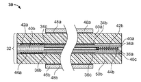
다음의 개시는 유전성 엘라스토머 층을 포함하는 전기활성 중합체 필름 - 유전성 엘라스토머 층의 일부분은 제1 및 제2 전극 사이에서 연신되고, 전극들의 적어도 하나의 중첩 부분은 활성 필름 영역을 형성하고, 필름의 적어도 하나의 잔여 부분은 불활성 필름 영역을 형성함 -; 불활성 필름 영역의 적어도 일부분 상에 배치되고 제1 전극에 전기적으로 커플링된 제1 전도성 층, 및 불활성 필름 영역의 적어도 일부분 상에 배치되고 제2 전극에 전기적으로 커플링된 제2 전도성 층; 및 전기활성 중합체 층의 하나의 면의 적어도 일부분 위에서 연장하는 적어도 하나의 수동 비압축성 중합체 층 - 활성 영역의 활성화는 비압축성 수동 중합체 층의 두께 치수를 변화시킴 - 을 포함하는 트랜스듀서를 또한 포함한다.The following disclosure discloses an electroactive polymer film comprising a dielectric elastomer layer, wherein a portion of the dielectric elastomer layer is stretched between the first and second electrodes, at least one overlapping portion of the electrodes forms an active film region, and at least a portion of the film One remaining portion forms an inert film region; A first conductive layer disposed on at least a portion of the inert film region and electrically coupled to the first electrode, and a second conductive layer disposed on at least a portion of the inert film region and electrically coupled to the second electrode; And at least one passive incompressible polymer layer extending over at least a portion of one side of the electroactive polymer layer, wherein activation of the active region changes the thickness dimension of the incompressible passive polymer layer.
트랜스듀서는 제1 및 제2 수동 비압축성 중합체 층을 선택적으로 포함할 수 있고, 제1 및 제2 수동 비압축성 중합체 층은 전기활성 중합체 필름의 각각의 면 상에 위치된다.The transducer can optionally include a first and a second passive incompressible polymer layer, wherein the first and second passive incompressible polymer layer are located on each side of the electroactive polymer film.
다른 변경예에서, 트랜스듀서 어셈블리는 전기활성 중합체 필름의 적어도 2개의 적층된 층 - 각각의 전기활성 중합체 필름은 얇은 유전성 엘라스토머 층을 포함하고, 유전성 엘라스토머 층의 일부분은 제1 및 제2 전극 사이에 삽입되고, 전극들의 중첩 부분은 활성 필름 영역을 형성하고 필름의 잔여 부분은 불활성 필름 영역을 형성하고, 전기활성 중합체 필름의 각각의 층의 활성 필름 영역들은 정렬되어 적층되고, 전기활성 중합체 필름의 각각의 층의 불활성 필름 영역들은 정렬되어 적층됨 -; 각각의 전기활성 중합체 필름의 불활성 필름 영역의 적어도 일부분 상에 배치되고 그의 제1 전극에 전기적으로 커플링된 제1 전도성 층, 및 각각의 전기활성 중합체 필름의 불활성 필름 영역의 적어도 일부분 상에 배치되고 그의 제2 전극에 전기적으로 커플링된 제2 전도성 층; 및 전기활성 중합체 필름의 각각의 노출된 면 위의 수동 비압축성 중합체 층 - 활성 영역의 활성화는 수동 비압축성 중합체 층의 두께 치수를 변화시킴 - 을 포함할 수 있다.In another variation, the transducer assembly includes at least two laminated layers of electroactive polymer film, each electroactive polymer film comprising a thin dielectric elastomer layer, wherein a portion of the dielectric elastomer layer is disposed between the first and second electrodes. Inserted, the overlapping portions of the electrodes form the active film region and the remaining portion of the film form the inert film region, the active film regions of each layer of the electroactive polymer film aligned and stacked, and each of the electroactive polymer films Inert film regions of the layer of layers are aligned and stacked; A first conductive layer disposed on at least a portion of the inert film region of each electroactive polymer film and electrically coupled to its first electrode, and disposed on at least a portion of the inert film region of each electroactive polymer film and A second conductive layer electrically coupled to its second electrode; And a passive incompressible polymer layer on each exposed side of the electroactive polymer film, wherein activation of the active region changes the thickness dimension of the passive incompressible polymer layer.
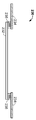
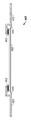
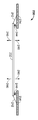
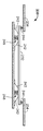
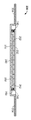
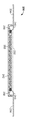
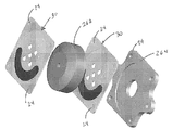
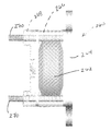
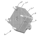
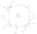
다음의 개시는 관성 전기활성 중합체 트랜스듀서를 또한 포함한다. 하나의 변경예에서, 관성 전기활성 중합체 트랜스듀서는 상부 및 하부 프레임 구성요소 사이에서 연신되는 전기활성 중합체 필름 - 프레임의 중심 부분이 전기활성 중합체 필름의 중심 표면을 노출하도록 개방됨 -; 전기활성 중합체 필름의 중심 표면 상의 제1 출력 부재; 및 출력 디스크에 고정된 적어도 하나의 관성 질량체 - 전기활성 중합체 필름 상의 제1 및 제2 전극을 가로지른 전압차의 인가는 중합체 필름의 변위를 일으켜서, 관성 질량체가 이동하게 함 - 를 포함한다.The following disclosure also includes inertial electroactive polymer transducers. In one variation, the inertial electroactive polymer transducer is an electroactive polymer film drawn between the upper and lower frame components, wherein the central portion of the frame is open to expose the central surface of the electroactive polymer film; A first output member on the central surface of the electroactive polymer film; And at least one inertial mass fixed to the output disk, wherein the application of the voltage difference across the first and second electrodes on the electroactive polymer film causes displacement of the polymer film, causing the inertial mass to move.
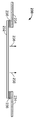
관성 전기활성 중합체 트랜스듀서의 추가의 변경예는 상부 및 하부 제2 프레임 구성요소 사이에 삽입된 제2 전기활성 중합체 필름 - 제2 프레임의 중심 부분이 전기활성 중합체 필름의 제2 중심 표면을 노출하도록 개방됨 -; 및 전기활성 중합체 필름의 중심 표면 상의 제2 출력 부재 - 관성 질량체는 제1 및 제2 출력 부재 사이에 고정되어 위치됨 - 를 포함한다.A further variation of the inertial electroactive polymer transducer is a second electroactive polymer film inserted between the upper and lower second frame components, such that the central portion of the second frame exposes the second central surface of the electroactive polymer film. Opened-; And a second output member on the central surface of the electroactive polymer film, wherein the inertial mass is fixedly positioned between the first and second output members.
본 장치 및 시스템은 많은 유형의 입력 장치 내에 채용될 수 있으므로 더 큰 유연성을 제공하고, 복수의 입력 요소로부터 피드백을 제공한다. 시스템은 또한 장치의 기계적 복잡성 또는 장치의 질량 및 중량을 실질적으로 추가하지 않으므로, 유리하다. 시스템은 또한 임의의 기계적 활주 또는 회전 요소가 없이 그의 기능을 달성하여, 시스템을 내구적이며, 조립이 간단하고, 쉽게 제조될 수 있게 한다.The apparatus and system can be employed within many types of input devices, providing greater flexibility and providing feedback from multiple input elements. The system is also advantageous as it does not substantially add the mechanical complexity of the device or the mass and weight of the device. The system also achieves its function without any mechanical slides or rotating elements, making the system durable, simple to assemble and easily manufactured.
본 발명은 컴퓨터, 전화, PDA, 비디오 게임 콘솔, GPS 시스템, 키오스크 장치 등을 위한 터치 패드, 터치 스크린 또는 키패드 등을 포함하지만 이들로 제한되지 않는 임의의 유형의 사용자 인터페이스 장치 내에 채용될 수 있다.The present invention may be employed in any type of user interface device including but not limited to touch pads, touch screens or keypads for computers, telephones, PDAs, video game consoles, GPS systems, kiosk devices, and the like.
본 발명의 다른 세부 사항에 관하여, 재료 및 대안적인 관련 구성은 관련 기술 분야의 당업자의 수준 내에서 채용될 수 있다. 이는 일반적으로 또는 논리적으로 채용되는 바와 같이 추가의 작용의 측면에서 본 발명의 방법에 기초한 태양에 대해 유효할 수 있다. 또한, 본 발명이 다양한 특징을 선택적으로 포함하는 여러 예를 참조하여 설명되었지만, 본 발명은 본 발명의 각각의 변경예에 대해 고려되는 것으로 설명되거나 표시된 것으로 제한되어서는 안된다. 다양한 변화가 설명된 본 발명에 대해 이루어질 수 있고, (본 명세서에서 언급되었든지 또는 간단하게 하기 위해 포함되지 않았든지 간에) 등가물이 본 발명의 진정한 사상 및 범주로부터 벗어남이 없이 대체될 수 있다. 도시된 임의의 개수의 개별 부품 또는 하위 어셈블리는 그들의 설계에 있어서 통합될 수 있다. 그러한 변화 등은 조립을 위한 설계의 원리에 의해 취해지거나 안내될 수 있다.With respect to other details of the invention, materials and alternative related configurations may be employed within the level of those skilled in the art. This may be valid for aspects based on the methods of the present invention in terms of further action as generally or logically employed. In addition, while the present invention has been described with reference to various examples that optionally include various features, the present invention should not be limited to what has been described or indicated as being considered for each variation of the invention. Various changes may be made to the described invention, and equivalents (whether referred to herein or not included for the sake of simplicity) may be substituted without departing from the true spirit and scope of the invention. Any number of individual parts or subassemblies shown may be integrated in their design. Such changes and the like can be taken or guided by the principles of the design for assembly.
본 발명의 이들 및 다른 특징, 목적 및 이점은 아래에서 더 상세하게 설명되는 바와 같은 본 발명의 세부를 읽을 때 본 기술 분야의 당업자에게 명백해질 것이다.These and other features, objects, and advantages of the present invention will become apparent to those skilled in the art upon reading the details of the present invention as described in more detail below.
본 발명은 첨부된 개략적인 도면과 관련하여 읽힐 때 다음의 상세한 설명으로부터 가장 잘 이해된다. 이해를 돕기 위해, 동일한 도면 부호는 도면들에 대해 공통된 유사한 요소를 표시하도록 (실질적인 경우에) 사용되었다. 다음이 도면에 포함되어 있다.
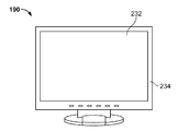
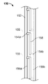
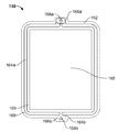
도 1a 및 1b는 EAP 트랜스듀서가 디스플레이 스크린 또는 센서 및 장치의 본체에 커플링되었을 때 햅틱 피드백을 채용할 수 있는 사용자 인터페이스의 몇몇 예를 도시한다.
도 2a 및 2b는 사용자 입력에 대한 햅틱 피드백과 반응하는 표면을 갖는 디스플레이 스크린을 포함하는 사용자 인터페이스 장치의 단면도를 도시한다.
도 3a 및 3b는 활성 가스켓으로 형성된 활성 EAP를 갖는 가요성 멤브레인에 의해 덮인 디스플레이 스크린을 갖는 사용자 인터페이스 장치의 다른 변경예의 단면도를 도시한다.
도 4는 디스플레이 스크린의 모서리 둘레에 위치된 스프링 편위식 EAP 멤브레인을 갖는 사용자 인터페이스 장치의 추가의 변경예의 단면도를 도시한다.
도 5는 디스플레이 스크린이 다수의 순응성 가스켓을 사용하여 프레임에 커플링되고 디스플레이를 위한 구동력이 다수의 EAP 액츄에이터 다이어프램인, 사용자 인터페이스 장치의 단면도를 도시한다.
도 6a 및 6b는 디스플레이 사이에 커플링된 주름진 EAP 멤브레인 또는 필름을 갖는 사용자 인터페이스(230)의 단면도를 도시한다.
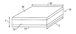
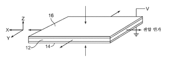
도 7a 및 7b는 본 발명의 일 실시양태에 따른 전압의 인가 전후의 트랜스듀서의 상부 사시도를 도시한다.
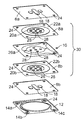
도 8a 및 8b는 사용자 인터페이스 장치 내에서 사용하기 위한 감각 피드백 장치의 분해된 상부 및 저면 사시도를 각각 도시한다.
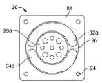
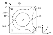
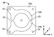
도 9a는 본 발명의 조립된 전기활성 중합체 액츄에이터의 평면도이고; 도 9b 및 9c는 각각 도 8a의 액츄에이터의 필름 부분의 평면도 및 저면도이며, 특히 액츄에이터의 2상 구성을 도시한다.
도 9d 및 9e는 장치의 프레임으로부터 이격된 디스플레이 스크린의 표면을 가로질러 위치하기 위한 전기활성 중합체 트랜스듀서의 어레이의 하나의 예를 도시한다.
도 9f 및 9g는 각각 본 명세서에서 개시되는 바와 같은 사용자 인터페이스 장치 내에서 사용하기 위한 액츄에이터의 어레이의 분해도 및 조립도이다.
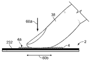
도 10은 사람 손가락이 장치의 접촉 표면과 작동식으로 접촉하는, 사용자 인터페이스 장치의 측면도를 도시한다.
도 11a 및 11b는 단상 모드로 작동될 때의 도 9a-9c의 액츄에이터의 힘-스트로크 관계 및 전압 응답 곡선을 각각 그래프로 도시한다.
도 12a 및 12b는 2상 모드로 작동할 때의 도 9a-9c의 액츄에이터의 힘-스트로크 관계 및 전압 응답 곡선을 각각 그래프로 도시한다.
도 13은 감각 피드백 장치를 작동시키기 위한, 전원 및 제어 전자 장치를 포함하는, 전자 회로의 블록 선도이다.
도 14a 및 14b는 사용자 입력 장치에 커플링된 EAP 액츄에이터의 평면 어레이의 하나의 예의 부분 단면도를 도시한다.
도 15a 및 15b는 트랜스듀서가 활성화될 때 작업 출력을 제공하기 위한 중합체 표면 특징부를 이용하는 액츄에이터로서 채용된 표면 변형 EAP 트랜스듀서를 개략적으로 도시한다.
도 16a 및 16b는 본 발명의 액츄에이터의 예시적인 구성의 단면도이다.
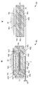
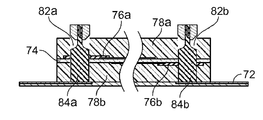
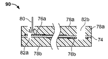
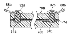
도 17a-17d는 인쇄 회로 기판(PCB) 또는 가요성 커넥터에 커플링하도록 본 트랜스듀서 내에 전기적 연결부를 만들기 위한 공정의 다양한 단계를 도시한다.
도 18a-18d는 전선에 커플링하도록 본 트랜스듀서 내에 전기적 연결부를 만들기 위한 공정의 다양한 단계를 도시한다.
도 19는 관통형 전기 접속부를 갖는 본 트랜스듀서의 단면도이다.
도 20a 및 20b는 각각 버튼-유형 액츄에이터 내에서의 용도에 대한, 두께 모드 트랜스듀서 및 전극 패턴의 평면도이다.
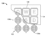
도 21은 도 6a 및 6b의 버튼-유형 액츄에이터의 어레이를 채용한 키패드의 상부 절결도를 도시한다.
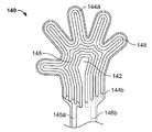
도 22는 사람 손 형태의 신규한 액츄에이터 내에서 사용하기 위한 두께 모드 트랜스듀서의 평면도를 도시한다.
도 23은 연속 스트립 구성의 두께 모드 트랜스듀서의 평면도를 도시한다.
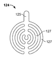
도 24는 가스켓형 액츄에이터 내에서의 용도에 대한 두께 모드 트랜스듀서의 평면도를 도시한다.
도 25a-25d는 다양한 유형의 가스켓형 액츄에이터를 채용한 터치 스크린의 단면도이다.
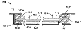
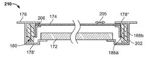
도 26a 및 26b는 트랜스듀서의 활성 및 수동 영역의 상대 위치가 상기 실시양태로부터 역전된 본 발명의 두께 모드 트랜스듀서의 다른 실시양태의 단면도이다.
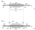
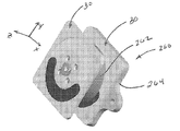
도 27a-27d는 전기활성 관성 트랜스듀서의 하나의 예를 도시한다.
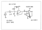
도 28a는 전기활성 중합체 액츄에이터에 대한 최적의 햅틱 진동수 내에서 작동하도록 청각 신호를 조절하기 위한 회로의 하나의 예를 도시한다.
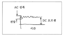
도 28b는 도 28a의 회로에 의해 필터링된 수정된 햅틱 신호의 하나의 예를 도시한다.
도 28c 및 28f는 단상 및 2상 전기활성 트랜스듀서를 위한 신호를 생성하기 위한 추가의 회로를 도시한다.
도 28e 및 28f는 장치 본체 내에 하나 이상의 전기활성 중합체 액츄에이터를 가지며 관성 질량체에 커플링된 장치의 하나의 예를 도시한다.
도면에 도시된 것으로부터의 본 발명의 변경예가 고려된다.The invention is best understood from the following detailed description when read in conjunction with the accompanying schematic drawings. For ease of understanding, the same reference numerals have been used (in practical cases) to indicate similar elements common to the figures. The following is included in the drawings.
1A and 1B show some examples of a user interface that may employ haptic feedback when an EAP transducer is coupled to a display screen or sensor and the body of the device.
2A and 2B illustrate cross-sectional views of a user interface device including a display screen having a surface that reacts with haptic feedback for user input.
3A and 3B show cross-sectional views of another variation of a user interface device having a display screen covered by a flexible membrane having an active EAP formed from an active gasket.
4 shows a cross-sectional view of a further variation of a user interface device having a spring biased EAP membrane positioned around an edge of the display screen.
5 shows a cross-sectional view of a user interface device wherein the display screen is coupled to the frame using multiple compliant gaskets and the driving force for the display is multiple EAP actuator diaphragms.
6A and 6B show cross-sectional views of
7A and 7B illustrate a top perspective view of a transducer before and after application of a voltage in accordance with one embodiment of the present invention.
8A and 8B show exploded top and bottom perspective views, respectively, of a sensory feedback device for use within a user interface device.
9A is a top view of the assembled electroactive polymer actuator of the present invention; 9B and 9C are top and bottom views, respectively, of the film portion of the actuator of FIG. 8A, and in particular show a two-phase configuration of the actuator.
9D and 9E show one example of an array of electroactive polymer transducers for positioning across the surface of a display screen spaced from the frame of the device.
9F and 9G are exploded and assembled views, respectively, of an array of actuators for use within a user interface device as disclosed herein.
10 illustrates a side view of a user interface device with a human finger in operative contact with a contact surface of the device.
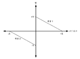
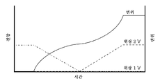
11A and 11B graphically depict the force-stroke relationship and voltage response curves of the actuators of FIGS. 9A-9C when operated in single phase mode, respectively.
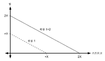
12A and 12B graphically depict the force-stroke relationship and voltage response curves of the actuators of FIGS. 9A-9C when operating in two phase mode, respectively.
13 is a block diagram of an electronic circuit, including a power supply and a control electronics, for operating a sensory feedback device.
14A and 14B show partial cross-sectional views of one example of a planar array of EAP actuators coupled to a user input device.
15A and 15B schematically illustrate a surface modified EAP transducer employed as an actuator using polymer surface features to provide a work output when the transducer is activated.
16A and 16B are cross-sectional views of exemplary configurations of the actuator of the present invention.
17A-17D illustrate various steps in the process for making electrical connections within the present transducer to couple to a printed circuit board (PCB) or flexible connector.
18A-18D illustrate various stages of the process for making electrical connections within the present transducer to couple to wires.
19 is a sectional view of the present transducer with a through-type electrical connection.
20A and 20B are plan views of thickness mode transducers and electrode patterns, respectively, for use in button-type actuators.
FIG. 21 shows a top cutaway view of a keypad employing the array of button-type actuators of FIGS. 6A and 6B.
22 shows a top view of a thickness mode transducer for use in a novel actuator in the form of a human hand.
23 shows a top view of a thickness mode transducer in a continuous strip configuration.
24 shows a top view of a thickness mode transducer for use in a gasketed actuator.
25A-25D are cross-sectional views of touch screens employing various types of gasketed actuators.
26A and 26B are cross-sectional views of another embodiment of the thickness mode transducer of the present invention in which the relative positions of the active and passive regions of the transducer are reversed from the above embodiment.
27A-27D illustrate one example of an electroactive inertial transducer.
28A shows one example of circuitry for adjusting the auditory signal to operate within an optimal haptic frequency for an electroactive polymer actuator.
FIG. 28B shows one example of a modified haptic signal filtered by the circuit of FIG. 28A.
28C and 28F show additional circuitry for generating signals for single phase and two phase electroactive transducers.
28E and 28F illustrate one example of a device having one or more electroactive polymer actuators in the device body and coupled to an inertial mass.
Modifications of the invention from those shown in the figures are contemplated.
발명의 상세한 설명Detailed description of the invention
본 발명의 장치, 시스템 및 방법이 이제 첨부된 도면을 참조하여 상세하게 설명된다.The apparatus, system and method of the present invention are now described in detail with reference to the accompanying drawings.
위에서 기술한 바와 같이, 사용자 인터페이스를 요구하는 장치는 장치의 사용자 스크린 상에서의 햅틱 피드백의 사용에 의해 개선될 수 있다. 도 1a 및 1b는 그러한 장치(190)의 단순한 예를 도시한다. 각각의 장치는 사용자가 데이터를 입력하거나 보기 위한 디스플레이 스크린(232)을 포함한다. 디스플레이 스크린은 장치의 본체 또는 프레임(234)에 커플링된다. 명확하게는, 임의의 개수의 장치가 휴대용 (예컨대, 휴대 전화, 컴퓨터, 제조 장비 등)이든지 다른 비휴대용 구조물 (예컨대, 정보 디스플레이 패널의 스크린, 현금 입출금기 스크린 등)에 고정되든 지에 관계없이 본 발명의 범주 내에 포함된다. 본 발명의 목적으로, 디스플레이 스크린은 터치패드형 장치를 또한 포함할 수 있고, 사용자 입력 또는 상호 작용은 실제 터치패드 (예컨대, 랩탑 컴퓨터 터치패드)로부터 떨어진 모니터 또는 장소 상에서 발생한다.As described above, devices requiring a user interface can be improved by the use of haptic feedback on the user screen of the device. 1A and 1B show a simple example of such a
다수의 설계 고려 사항은 특히 디스플레이 스크린(232)의 햅틱 피드백을 추구할 때 트랜스듀서의 제작을 위해, "전기활성 중합체"(EAP)로도 불리는, 개선된 유전성 엘라스토머 물질의 선택 및 사용을 선호한다. 이러한 고려 사항은 전위력, 전력 밀도, 전력 변환/소비, 크기, 중량, 비용, 응답 시간, 듀티 사이클, 서비스 요건, 환경적 충격 등을 포함한다. 이와 같이, 많은 용도에서, EAP 기술은 압전 장치, 형상 기억 합금(SMA), 및 모터 및 솔레노이드와 같은 전자기 장치에 대한 이상적인 대체물을 제공한다.Many design considerations favor the selection and use of improved dielectric elastomer materials, also referred to as "electroactive polymers" (EAPs), especially for the fabrication of transducers when seeking haptic feedback of
EAP 트랜스듀서는 탄성 특징을 가지며 얇은 엘라스토머 유전 물질에 의해 분리된 2개의 얇은 필름 전극을 포함한다. 전압차가 전극에 인가될 때, 반대로 대전된 전극들은 서로 끌어당겨서, 그들 사이의 중합체 유전체 층을 압축시킨다. 전극들이 함께 더 가까이 당겨짐에 따라, 유전성 중합체 필름은 그가 평면 방향으로 팽창하므로 (x 및 y 축 성분이 팽창하므로), 더 얇아진다 (z 축 성분이 수축한다).EAP transducers have two thin film electrodes that are elastic and are separated by a thin elastomeric dielectric material. When a voltage difference is applied to the electrodes, the oppositely charged electrodes attract each other, compressing the polymer dielectric layer between them. As the electrodes are pulled closer together, the dielectric polymer film becomes thinner (since the z and y axis components expand) as it expands in the planar direction (the z axis components shrink).
도 2a-2b는 디스플레이 스크린 상의 정보, 제어, 또는 자극에 응답하여 사용자에 의해 물리적으로 터치되는 표면을 갖는 디스플레이 스크린(232)을 갖는 사용자 인터페이스 장치(230)의 일부분을 도시한다. 디스플레이 스크린(232)은 액정 디스플레이(LCD), 유기 발광 다이오드(OLED) 등과 같은 임의의 유형의 터치 패드 또는 스크린 패널일 수 있다. 또한, 인터페이스 장치(230)의 변경예는 이미지가 스크린 상에 전치되는 "더미" 스크린 (예컨대, 프로젝터 또는 영상막)과 같은 디스플레이 스크린(232)을 포함할 수 있고, 스크린은 보편적인 모니터 또는 일반적인 간판 또는 디스플레이와 같은 고정된 정보를 갖는 스크린도 포함할 수 있다.2A-2B illustrate portions of a
어떠한 경우에도, 디스플레이 스크린(232)은 프레임(234) (또는 하우징 또는 직접 연결 또는 하나 이상의 접지 요소에 의해 장치에 스크린을 기계적으로 연결하는 임의의 다른 구조물), 및 프레임 또는 하우징(234)에 스크린(232)을 커플링시키는 전기활성 중합체(EAP) 트랜스듀서(236)를 포함한다. 본 명세서에서 기술되는 바와 같이, EAP 트랜스듀서는 스크린(232)의 모서리를 따라 있을 수 있거나, EAP 트랜스듀서의 어레이가 프레임 또는 하우징(234)으로부터 이격된 스크린(232)의 부분과 접촉하여 위치될 수 있다.In any case, the
도 2a 및 2b는 봉지된 EAP 트랜스듀서(236)가 활성 가스켓을 형성하는 기본적인 사용자 인터페이스 장치를 도시한다. 임의의 개수의 활성 가스켓 EAP(236)가 터치 스크린(232)과 프레임(234) 사이에 커플링될 수 있다. 전형적으로, 충분한 활성 가스켓 EAP(236)가 원하는 햅틱 감각을 생성하도록 제공된다. 그러나, 개수는 흔히 특정 용도에 의존하여 변할 것이다. 장치의 변경예에서, 터치 스크린(232)은 디스플레이 스크린 또는 센서 플레이트를 포함할 수 있다 (디스플레이 스크린은 센서 플레이트 후방에 있을 것임).2A and 2B illustrate a basic user interface device in which encapsulated
도면은 터치 스크린(232)을 불활성 상태와 활성 상태 사이에서 순환시키는 사용자 인터페이스 장치(230)를 도시한다. 도 2a는 터치 스크린(232)이 불활성 상태에 있는 사용자 인터페이스 장치(230)를 도시한다. 그러한 상태에서, 전기장이 EAP 트랜스듀서(236)에 인가되지 않아서, 트랜스듀서가 휴지 상태에 있도록 허용한다. 도 2b는 일부 사용자 입력이 EAP 트랜스듀서(236)를, 트랜스듀서(236)가 디스플레이 스크린(232)을 화살표(238)에 의해 도시된 방향으로 이동하게 하는 활성 상태로 트리거링한 후의 사용자 인터페이스 장치(230)를 도시한다. 대안적으로, 하나 이상의 EAP 트랜스듀서(236)의 변위는 디스플레이 스크린(232)의 방향성 이동을 생성하도록 변할 수 있다 (예컨대, 전체 디스플레이 스크린(232)이 균일하게 이동하기보다는, 스크린(232)의 하나의 영역이 다른 영역보다 더 큰 정도로 변위할 수 있음). 명확하게는, 사용자 인터페이스 장치(230)에 커플링된 제어 시스템이 원하는 진동수로 EAP(236)를 순환시키고/거나 EAP(236)의 변형의 양을 변경하도록 구성될 수 있다.The figure shows a
도 3a 및 3b는 디스플레이 스크린(232)을 보호하도록 기능하는 가요성 멤브레인(240)에 의해 덮인 디스플레이 스크린(232)을 갖는 사용자 인터페이스 장치(230)의 다른 변경예를 도시한다. 다시, 장치는 기부 또는 프레임(234)에 디스플레이 스크린(232)을 커플링시키는 다수의 활성 가스켓 EAP(236)를 포함할 수 있다. 사용자 입력에 응답하여, 스크린(232)은 멤브레인(240)과 함께, 전기장이 EAP(236)에 인가될 때 변위하여, 장치(230)가 활성 상태로 진입하도록 변위를 일으킨다.3A and 3B show another variation of the
도 4는 디스플레이 스크린(232)의 모서리 둘레에 위치된 스프링 편위식 EAP 멤브레인(242)을 갖는 사용자 인터페이스 장치(230)의 추가의 변경예를 도시한다. EAP 멤브레인(242)은 스크린의 주변부 둘레에 또는 스크린이 사용자에게 햅틱 피드백을 생성하도록 허용하는 위치 내에만 위치될 수 있다. 이러한 변경예에서, 수동 순응성 가스켓 또는 스프링(244)이 스크린(232)에 대항하여 힘을 제공하여, EAP 멤브레인(242)을 인장 상태에 둔다. 멤브레인(242)에 전기장을 제공할 때 (다시, 신호가 사용자 입력에 의해 발생되면), EAP 멤브레인(242)은 이완되어 스크린(232)의 변위를 일으킨다. 화살표(246)에 의해 표시된 바와 같이, 사용자 입력 장치(230)는 가스켓(244)에 의해 제공되는 편위에 대해 임의의 방향으로 스크린(232)의 이동을 생성하도록 구성될 수 있다. 또한, 일부 EAP 멤브레인(242)의 작동은 스크린(232)의 불균일 이동을 생성한다.4 shows a further variation of the
도 5는 사용자 인터페이스 장치(230)의 또 다른 변경예를 도시한다. 이러한 예에서, 디스플레이 스크린(232)은 다수의 순응성 가스켓(244)을 사용하여 프레임(234)에 커플링되고, 디스플레이(232)를 위한 구동력은 다수의 EAP 액츄에이터 다이어프램(248)이다. EAP 액츄에이터 다이어프램(248)은 스프링 편위식이고, 전기장의 인가 시에, 디스플레이 스크린을 구동할 수 있다. 도시된 바와 같이, EAP 액츄에이터 다이어프램(248)은 스프링의 각 면 상에서 대향하는 EAP 멤브레인을 갖는다. 그러한 구성에서, EAP 액츄에이터 다이어프램(248)의 대향 면들을 활성화하는 것은 중립 점에서 어셈블리를 강성으로 만든다. EAP 액츄에이터 다이어프램(248)은 사람의 팔의 이동을 제어하는 대향하는 이두박근 및 삼두박근처럼 작용한다. 도시되지는 않았지만, 미국 특허 출원 제11/085,798호 및 제11/085,804호에 개시되어 있는 바와 같이, 액츄에이터 다이어프램(248)은 2상 출력 작용을 제공하고/거나 더 강건한 용도에서의 사용을 위해 출력을 증폭시키도록 적층될 수 있다.5 illustrates another modification of the
도 6a 및 6b는 EAP 필름(242) 내에 주름 또는 접힘부를 수용하도록 다수의 지점 또는 접지 요소(252)에서 디스플레이(232)와 프레임(234) 사이에 커플링된 EAP 멤브레인 또는 필름(242)을 갖는 사용자 인터페이스(230)의 다른 변경예를 도시한다. 도 6b에 도시된 바와 같이, EAP 필름(242)에 대한 전기장의 인가는 주름의 방향으로의 변위를 일으키고, 프레임(234)에 대해 디스플레이 스크린(232)을 변형시킨다. 사용자 인터페이스(230)는 디스플레이(232)와 프레임(234) 사이에 커플링된 편위 스프링(250) 및/또는 디스플레이 스크린(232)의 일부분 (또는 전부)를 덮는 가요성 보호 멤브레인(240)을 선택적으로 포함할 수 있다.6A and 6B have an EAP membrane or
위에서 논의된 도면들은 EAP 필름 또는 트랜스듀서를 채용하는 그러한 촉각 피드백 장치의 예시적인 구성을 개략적으로 도시하는 것으로 기술되었다. 많은 변경예가 본 발명의 범주 내에 있고, 예를 들어, 장치의 변경예에서, EAP 트랜스듀서는 전체 스크린 또는 패드 어셈블리보다는 센서 플레이트 또는 요소 (예컨대, 사용자 입력 시에 트리거링되고 EAP 트랜스듀서에 신호를 제공하는 것)만을 이동시키도록 구현될 수 있다.The figures discussed above have been described as schematically illustrating an exemplary configuration of such a tactile feedback device employing an EAP film or transducer. Many variations are within the scope of the present invention, for example, in a variation of the device, the EAP transducer is triggered at the user input and provides a signal to the EAP transducer rather than the entire screen or pad assembly. Only).
임의의 용도에서, EAP 부재에 의한 디스플레이 스크린 또는 센서 플레이트의 피드백 변위는 전적으로 측방 이동으로서 감지되는 평면내일 수 있거나, (수직 변위로서 감지되는) 평면외일 수 있다. 대안적으로, EAP 트랜스듀서 재료는 플레이트 요소의 각도 변위를 제공하기 위해 주소 지정/이동 가능한 섹션들을 독립적으로 제공하도록 단편화될 수 있다. 또한, 임의의 개수의 EAP 트랜스듀서 또는 필름이 (상기에 열거된 특허 출원 및 특허에 개시되어 있는 바와 같이) 본 명세서에서 설명되는 사용자 인터페이스 장치 내에 통합될 수 있다.In any application, the feedback displacement of the display screen or sensor plate by the EAP member may be in-plane, which is perceived solely as lateral movement, or may be out-of-plane (sensed as vertical displacement). Alternatively, the EAP transducer material can be fragmented to independently provide addressable / movable sections to provide angular displacement of the plate element. In addition, any number of EAP transducers or films may be incorporated into the user interface device described herein (as disclosed in the patent applications and patents listed above).
본 명세서에서 설명되는 장치의 변경예는 장치의 전체 센서 플레이트 (또는 디스플레이 스크린)이 촉각 피드백 요소로서 작용하도록 허용한다. 이는 광범위한 유연성을 허용한다. 예를 들어, 스크린은 가상 키 스트로크에 응답하여 한번 반발할 수 있거나, 스크린 상의 슬라이드 바와 같은 스크롤 요소에 대해 응답하여 연속된 반발을 출력할 수 있어서, 스크롤 휠의 기계적 멈춤쇠를 효과적으로 모의한다. 제어 시스템의 사용에 의해, 3차원 아웃라인(outline)이 스크린 상의 사용자 손가락의 정확한 위치를 판독하고 스크린 패널을 이에 따라 3D 구조를 모의하도록 이동시킴으로써 합성될 수 있다. 충분한 스크린 변위 및 스크린의 상당한 질량이 주어지면, 스크린의 반복된 오실레이션은 휴대 전화의 진동 기능을 대체할 수도 있다. 그러한 기능성은 텍스트의 브라우징(browsing)에 적용될 수 있고, 이때 텍스트의 1줄의 스크롤링(수직)이 촉각적 "요철"에 의해 표현되어 멈춤쇠를 모의한다. 비디오 게임의 맥락에서, 본 발명은 종래 기술의 비디오 게임 시스템에서 채용된 오실레이팅 진동 모터에 대해 증가된 상호 작용 및 더 미세한 움직임을 제공한다. 터치 패드의 경우에, 사용자 상호 작용 및 접근성이 물리적 암시신호를 제공함으로써, 특히 시각 장애인에 대해 개선될 수 있다.Modifications of the device described herein allow the entire sensor plate (or display screen) of the device to act as a tactile feedback element. This allows for a wide range of flexibility. For example, the screen may react once in response to a virtual key stroke or output a continuous reaction in response to a scroll element such as a slide bar on the screen, effectively simulating a mechanical detent of the scroll wheel. By using a control system, a three-dimensional outline can be synthesized by reading the exact position of the user's finger on the screen and moving the screen panel accordingly to simulate the 3D structure. Given sufficient screen displacement and significant mass of the screen, repeated oscillation of the screen may replace the vibration function of the mobile phone. Such functionality can be applied to the browsing of text, where a single line of scrolling (vertical) of text is represented by a tactile "unevenness" to simulate a detent. In the context of video games, the present invention provides increased interaction and finer motion for oscillating oscillating motors employed in prior art video game systems. In the case of touch pads, user interaction and accessibility can be improved by providing physical cues, especially for the visually impaired.
EAP 트랜스듀서는 인가된 전압에 비례하여 변위하도록 구성될 수 있고, 이는 본 촉각 피드백 장치와 함께 사용되는 제어 시스템의 프로그래밍을 용이하게 한다. 예를 들어, 소프트웨어 알고리즘이 픽셀 그레이스케일을 EAP 트랜스듀서 변위로 변환시킬 수 있고, 이에 의해 스크린 커서의 팁 아래의 픽셀 그레이스케일 값이 연속적으로 측정되고, EAP 트랜스듀서에 의한 비례 변위로 변환된다. 터치 패드를 가로질러 손가락을 이동시킴으로써, 거친 3D 질감을 느끼거나 감지할 수 있다. 유사한 알고리즘이 웹 페이지 상에서 적용될 수 있고, 이때 아이콘의 경계는 아이콘 위에서 손가락을 이동시킬 때, 페이지 질감의 요철 또는 버징(buzzing) 버튼으로서 사용자에게 피드백된다. 정상 사용자에 대해, 이는 웹 서핑 중에 완전히 새로운 감각 경험을 제공할 것이고, 시각 장애인에 대해, 이는 필수적인 피드백을 추가할 것이다.The EAP transducer can be configured to displace in proportion to the applied voltage, which facilitates programming of the control system used with the present tactile feedback device. For example, a software algorithm may convert pixel grayscale to EAP transducer displacement, whereby the pixel grayscale value under the tip of the screen cursor is measured continuously and converted to proportional displacement by the EAP transducer. By moving your finger across the touchpad, you can feel or sense a rough 3D texture. Similar algorithms can be applied on the web page, where the border of the icon is fed back to the user as an uneven or buzzing button of the page texture as the finger moves over the icon. For normal users, this will provide a whole new sensory experience while surfing the web, and for the visually impaired, this will add essential feedback.
EAP 트랜스듀서는 다수의 이유로 그러한 용도에 대해 이상적이다. 예를 들어, 그의 가벼운 중량 및 최소 구성요소들 때문에, EAP 트랜스듀서는 매우 낮은 프로파일을 제공하고, 이와 같이 감각/햅틱 피드백 용도에서의 사용에 대해 이상적이다.EAP transducers are ideal for such applications for a number of reasons. For example, because of its light weight and minimal components, the EAP transducer provides a very low profile and is thus ideal for use in sensory / haptic feedback applications.
도 7a 및 7b는 EAP 필름 또는 멤브레인(10) 구조물의 하나의 예를 도시한다. 얇은 엘라스토머 유전체 필름 또는 층(12)이 순응성 또는 연신 가능 전극 플레이트 또는 층(14, 16) 사이에 삽입되어, 용량성 구조물 또는 필름을 형성한다. 유전체 층과 복합 구조물의 길이("l") 및 폭("w")은 구조물의 두께("t")보다 훨씬 더 크다. 전형적으로, 유전체 층은 약 10 ㎛ 내지 약 100 ㎛ 범위 내의 두께를 갖고, 구조물의 총 두께는 약 25 ㎛ 내지 약 10 ㎝의 범위 내이다. 추가로, 전극이 액츄에이터에 기여하는 추가의 강성이 상대적으로 낮은 탄성 계수를 갖는 유전체 층(12)의 강성보다 대체로 더 낮고, 즉 약 100 MPa보다 더 낮고 더욱 전형적으로 약 10 MPa보다 더 낮지만, 각각의 전극보다 더 두꺼울 수 있도록, 전극(14, 16)의 탄성 계수, 두께, 및/또는 미세 기하학적 형상을 선택하는 것이 바람직하다. 이러한 순응성 용량성 구조물과 함께 사용하기에 적합한 전극은 기계적 피로로 인한 파손이 없이 약 1%보다 더 큰 주기적 스트레인을 견딜 수 있는 것이다.7A and 7B illustrate one example of an EAP film or
도 7b에서 보이는 바와 같이, 전압이 전극을 가로질러 인가될 때, 2개의 전극(14, 16) 내의 상이한 전하가 서로 끌어 당겨지고, 이러한 정전기 인력은 (Z 축을 따라) 유전체 필름(12)을 압축시킨다. 유전체 필름(12)은 이에 의해 전기장의 변화에 의해 변형된다. 전극(14, 16)이 순응성이므로, 이들은 유전체 층(12)과 함께 형상을 변화시킨다. 일반적으로, 변형은 유전체 필름(12)의 일부분의 임의의 변위, 팽창, 수축, 비틀림, 선 또는 면적 스트레인, 또는 임의의 다른 변형을 말한다. 용량성 구조물(10)이 채용되는 형상 맞춤 구성, 예컨대 프레임 (집합적으로, "트랜스듀서"로 불림)에 의존하여, 이러한 변형은 기계적 작업을 생성하도록 사용될 수 있다. 여러 상이한 트랜스듀서 구성이 전술한 특허 참조 문헌에 개시되고 설명되어 있다.As shown in FIG. 7B, when voltage is applied across the electrodes, different charges in the two
전압이 인가되면, 트랜스듀서 필름(10)은 기계적 힘이 변형을 구동하는 정전기 힘과 균형을 이룰 때까지 계속하여 변형된다. 기계적 힘은 유전체 층(12)의 탄성 복원력, 전극(14, 16)의 순응성 또는 연신성, 및 트랜스듀서(10)에 커플링된 장치 및/또는 부하에 의해 제공되는 임의의 외부 저항을 포함한다. 인가된 전압의 결과인 트랜스듀서(10)의 결과적인 변형은 또한 엘라스토머 물질의 유전 상수 및 그의 크기 및 강성과 같은 다수의 다른 인자에 의존할 수 있다. 전압차 및 유도된 전하의 제거는 반대 효과를 일으킨다.When a voltage is applied, the
몇몇 경우에, 전극(14, 16)은 필름의 총 면적에 대해 유전체 필름(12)의 제한된 부분을 덮을 수 있다. 이는 유전체의 모서리 둘레에서의 전기적 파괴를 방지하거나 그의 소정의 부분 내에서 맞춤화형 변형을 달성하도록 행해질 수 있다. 활성 영역 외부의 유전 물질(활성 영역은 그러한 부분의 변형을 가능케 하기에 충분한 정전기 힘을 갖는 유전 물질의 부분임)은 변형 중에 활성 영역 상에서 외부 스프링력으로서 작용하게 될 수 있다. 더 구체적으로, 활성 영역 외부의 재료는 그의 수축 또는 팽창에 의해 활성 영역 변형에 저항하거나 향상시킬 수 있다.In some cases,
유전체 필름(12)은 예비 스트레인될 수 있다. 예비 스트레인은 전기 에너지와 기계적 에너지 사이의 변환을 개선하고, 즉 예비 스트레인은 유전체 필름(12)이 더 많이 변형하여 더 큰 기계적 작업을 제공하도록 허용한다. 필름의 예비 스트레인은 예비 스트레인 이전의 일 방향으로의 치수에 대한 예비 스트레인 이후의 일 방향으로의 치수의 변화로서 설명될 수 있다. 예비 스트레인은 유전체 필름의 탄성 변형을 포함할 수 있고, 예를 들어, 인장 시에 필름을 연신시키고 연신된 상태에서 모서리들 중 하나 이상을 고정시킴으로써 형성될 수 있다. 예비 스트레인은 필름의 경계에 또는 필름의 일부분에 대해서만 부여될 수 있고, 강성 프레임을 사용함으로써 또는 필름의 일부분은 강화시킴으로써 구현될 수 있다.
도 7a 및 7b의 트랜스듀서 구조 및 다른 유사한 순응성 구조와 그의 구성의 세부는 본 명세서에 개시된 참조된 특허 및 간행물들 중 많은 것에 더 상세하게 설명되어 있다.The details of the transducer structures and other similar compliant structures and configurations thereof of FIGS. 7A and 7B are described in more detail in many of the referenced patents and publications disclosed herein.
위에서 설명된 EAP 필름에 추가하여, 감각 또는 햅틱 피드백 사용자 인터페이스 장치는 측방 이동을 생성하도록 설계된 EAP 트랜스듀서를 포함할 수 있다. 예를 들어, 다양한 구성요소가, 도 8a 및 8b에 도시된 바와 같이 위에서부터 아래로, (위에서 기술한 바와 같이) 전기 에너지를 기계적 에너지로 변환시키는 탄성 필름 형태의 전기활성 중합체(EAP) 트랜스듀서(10)를 갖는 액츄에이터(30)를 포함한다. 결과적인 기계적 에너지는 여기서 디스크(28) 형태인 출력 부재의 물리적 "변위"의 형태이다.In addition to the EAP film described above, the sensory or haptic feedback user interface device can include an EAP transducer designed to produce lateral movement. For example, various components may be used in an electroactive polymer (EAP) transducer in the form of an elastic film that converts electrical energy into mechanical energy (as described above) from top to bottom, as shown in FIGS. 8A and 8B. And an
도 9a-9c를 참조하면, EAP 트랜스듀서 필름(10)은 얇은 탄성 전극(32a, 32b; 34a, 34b)의 2개의 작동 쌍을 포함하고, 여기서 각각의 작동 쌍은 (예컨대, 아크릴레이트, 실리콘, 우레탄, 열가소성 엘라스토머, 탄화수소 고무, 함불소 엘라스토머 등으로 만들어진) 엘라스토머 유전성 중합체(26)의 얇은 층에 의해 분리된다. 전압차가 각각의 작동 쌍의 반대 전하 전극을 가로질러 (즉, 전극(32a, 32b)을 가로질러 그리고 전극(34a, 34b)을 가로질러) 인가될 때, 대향 전극들은 서로 끌어당겨서 그들 사이의 유전성 중합체 층(26)을 압축시킨다. 전극들이 함께 더 가까이 당겨짐에 따라, 유전성 중합체(26)는 그가 평면 방향으로 팽창하므로 (즉, x 및 y 축 성분이 팽창하므로) 더 얇아진다 (즉, z 축 성분이 수축한다) (축 기준에 대해서는 도 9b 및 9c 참조). 또한, 각각의 전극을 가로질러 분포되는 유사 전하가 그러한 전극 내에 매립된 전도성 입자들이 서로 밀어내게 하여, 탄성 전극 및 유전체 필름의 팽창에 기여한다. 유전체 층(26)은 이에 의해 전기장의 변화에 의해 변형된다. 전극 재료가 또한 순응성이므로, 전극 층은 유전체 층(26)과 함께 형상을 변화시킨다. 일반적으로, 변형은 유전체 층(26)의 일부분의 임의의 변위, 팽창, 수축, 비틀림, 선 또는 면적 스트레인, 또는 임의의 다른 변형을 말한다. 이러한 변형은 기계적 작업을 생성하도록 사용될 수 있다.9A-9C, the
트랜스듀서(20) 제작 시에, 탄성 필름이 2개의 대향하는 강성 프레임 면(8a, 8b)에 의해 연신되고 예비 스트레인된 상태로 유지된다. 예비 스트레인은 중합체 층(26)의 유전 강도를 개선하여, 전기 에너지와 기계적 에너지 사이의 변환을 개선하고, 즉 예비 스트레인은 필름이 더 많이 변형되고 더 큰 기계적 작업을 제공하도록 허용하는 것이 관찰되었다. 전형적으로, 전극 재료는 중합체 층을 예비 스트레인시킨 후에 도포되지만, 미리 도포될 수도 있다. 본 명세서에서 동일면 전극 쌍으로 불리는 층(26)의 동일한 면 상에 제공된 2개의 전극, 즉 유전체 층(26)의 상부 면(26a) 상의 전극(32a, 34a)(도 9b 참조) 및 유전체 층(26)의 하부 면(26b) 상의 전극(32b, 34b)(도 9c 참조)은 불활성 영역 또는 갭(25)에 의해 서로로부터 전기적으로 절연된다. 중합체 층의 대향 면들 상의 대향 전극들이 작동 전극 쌍의 2개의 세트, 즉 하나의 작동 전극 쌍에 대한 전극(32a, 32b) 및 다른 작동 전극 쌍에 대한 전극(34a, 34b)을 형성한다. 각각의 동일면 전극 쌍은 바람직하게는 동일한 극성을 갖고, 각각의 작동 전극 쌍의 전극들의 극성은 서로 반대이고, 즉 전극(32a, 32b)은 반대로 대전되고, 전극(34a, 34b)은 반대로 대전된다. 각각의 전극은 전압원(도시되지 않음)에 대한 전기적 연결을 위해 구성된 전기 접속 부분(35)을 갖는다.In fabricating the
도시된 실시양태에서, 전극 각각은 반원형 구성을 갖고, 여기서 동일면 전극 쌍은 유전체 층(26)의 각각의 면 상에서 중심 배치된, 강성 출력 디스크(20a, 20b)를 수용하기 위한 실질적으로 원형인 패턴을 형성한다. 기능이 아래에서 설명되는 디스크(20a, 20b)은 중합체 층(26)의 중심 노출된 외측 표면(26a, 26b)에 고정되어, 그들 사이에 층(26)을 삽입한다. 디스크와 필름 사이의 커플링은 기계식이거나 접착 결합에 의해 제공될 수 있다. 일반적으로, 디스크(20a, 20b)는 트랜스듀서 프레임(22a, 22b)에 대해 크기가 결정될 것이다. 더 구체적으로, 프레임의 내측 환상 직경에 대한 디스크 직경의 비율은 트랜스듀서 필름(10)에 인가되는 응력을 적절하게 분배하도록 될 것이다. 프레임 직경에 대한 디스크 직경의 비율이 클수록, 피드백 신호의 힘 또는 이동은 더 크고, 디스크의 선형 변위는 더 낮다. 대안적으로, 비율이 낮을수록, 출력 힘은 더 낮고, 선형 변위는 더 크다.In the illustrated embodiment, each of the electrodes has a semicircular configuration, wherein the coplanar electrode pairs are substantially circular patterns for receiving
전극 구성에 의존하여, 트랜스듀서(10)는 단상 또는 2상 모드로 기능할 수 있다. 구성된 방식에서, 위에서 설명된 본 감각 피드백 장치의 출력 구성요소, 즉 2개의 커플링된 디스크(20a, 20b)의 기계적 변위는 수직이 아닌 측방이다. 바꾸어 말하면, 감각 피드백 신호가 사용자 인터페이스의 디스플레이 표면(232)에 대해 직각이고 (반대 또는 상향 방향으로의) 사용자 손가락(38)에 의해 인가되는 (도 10에서 화살표(60a)에 의해 표시된) 입력 힘에 대해 평행한 방향으로의 힘인 것 대신에, 본 발명의 감각/햅틱 피드백 장치의 (도 10에서 양방향 화살표(60b)에 의해 표시된) 감지되는 피드백 또는 출력 힘은 디스플레이 표면(232)에 대해 평행하고 입력 힘(60a)에 대해 직각 방향이다. 트랜스듀서(10)의 평면에 대해 직각인 축에 대한 그리고 트랜스듀서가 작동되는 디스플레이 표면(232) 모드(즉, 단상 또는 2상)의 위치에 대한 전극 쌍의 회전 정렬에 의존하여, 이러한 측방 이동은 360° 이내에서 임의의 방향 또는 방향들일 수 있다. 예를 들어, 측방 피드백 운동은 사용자 손가락 (또는 손하부 또는 파지 등)의 전방 방향에 대해 측면 방향 또는 상하 방향일 수 있다 (양자는 2상 작동임). 본 기술 분야의 당업자가 햅틱 피드백 장치의 접촉 표면에 대해 횡방향이거나 직각인 피드백 변위를 제공하는 소정의 다른 액츄에이터 구성을 인식할 것이지만, 이렇게 구성된 장치의 전체 프로파일은 전술한 설계보다 더 클 수 있다.Depending on the electrode configuration, the
도 9d-9g는 장치의 디스플레이 스크린을 가로질러 위치될 수 있는 전기활성 중합체의 어레이의 하나의 예를 도시한다. 이러한 예에서, EAP 필름 어레이(200)(도 9f 참조)의 전압 및 접지 측(200a, 200b)이 각각 본 발명이 촉각 피드백 장치 내에서 사용하기 위한 EAP 액츄에이터의 어레이 내에서 사용된다. 필름 어레이(200)는 공간 및 전력 효율을 증가시키고 제어 회로를 단순화하기 위한 매트릭스 구성으로 제공되는 전극 어레이를 포함한다. EAP 필름 어레이의 고전압 측(200a)은 유전체 필름(208) 물질 상에서 (도 9d에 도시된 방향에 따르면) 수직으로 이어지는 전극 패턴(202)을 제공한다. 각각의 패턴(202)은 한 쌍의 고전압 라인(202a, 202b)을 포함한다. EAP 필름 어레이의 대향 또는 접지 측(200b)은 고전압 전극에 대해 횡방향으로, 즉 수평으로 이어지는 전극 패턴(206)을 제공한다. 각각의 패턴(206)은 한 쌍의 접지 라인(206a, 206b)을 포함한다. 대향하는 고전압 및 접지 라인(202a, 206a; 202b, 206b)의 각각의 쌍은 대향 전극 쌍의 활성화가 화살표(212)에 의해 도시된 방향으로의 2상 출력 운동을 제공하도록 분리되어 활성화 가능한 전극 쌍을 제공한다. (유전체 필름(208)의 상부 및 하부 면 상의 전극들의 교차 패턴을 예시하는) 조립된 EAP 필름 어레이(200)가 EAP 트랜스듀서(222)의 어레이(204)의 분해도로 도 9f에서 제공되고, EAP 트랜스듀서의 어레이는 도 9g에서 그의 조립된 형태로 도시되어 있다. EAP 필름 어레이(200)는 대향하는 프레임 어레이(214a, 214b) 사이에 삽입되고, 2개의 어레이 각각 내의 각각의 개별 프레임 세그먼트(216)는 개방 영역 내의 중심 위치된 출력 디스크(218)에 의해 형성된다. 프레임/디스크 세그먼트(216) 및 전극 구성의 각각의 조합은 EAP 트랜스듀서(222)를 형성한다. 원하는 액츄에이터의 용도 및 유형에 의존하여, 구성요소들의 추가의 층이 트랜스듀서 어레이(204)에 추가될 수 있다. 트랜스듀서 어레이(220)는 예를 들어, 디스플레이 스크린, 센서 표면, 또는 터치 패드와 같은 사용자 인터페이스 어레이 내에 전체적으로 통합될 수 있다.9D-9G illustrate one example of an array of electroactive polymers that may be positioned across the display screen of the device. In this example, the voltage and
감각/햅틱 피드백 장치(2)를 단상 모드로 작동시킬 때, 액츄에이터(30)의 전극의 단지 하나의 작동 쌍이 임의의 일 시점에서 활성화된다. 액츄에이터(30)의 단상 작동은 단일 고전압 전원을 사용하여 제어될 수 있다. 단일 선택된 작동 전극 쌍에 인가되는 전압이 증가됨에 따라, 트랜스듀서 필름의 활성화된 부분(반부)이 팽창할 것이고, 이에 의해 출력 디스크(20)를 트랜스듀서 필름의 불활성 부분의 방향으로 평면내에서 이동시킨다. 도 11a는 2개의 작동 전극 쌍을 단상 모드로 교대로 활성화할 때의 중립 위치에 대한 액츄에이터(30)의 감각 피드백 신호(즉, 출력 디스크 변위)의 힘-스트로크 관계를 도시한다. 도시된 바와 같이, 출력 디스크의 각각의 힘 및 변위는 서로 동일하지만 반대 방향이다. 도 11b는 이러한 단상 모드로 작동될 때의 액츄에이터의 출력 변위에 대한 인가 전압의 결과적인 비선형 관계를 도시한다. 공유된 유전체 필름에 의한 2개의 전극 쌍의 "기계적" 커플링은 출력 디스크를 반대 방향으로 이동시키도록 될 수 있다. 따라서, 양 전극 쌍이 작동될 때, 서로 독립적일 지라도, 제1 작동 전극 쌍에 대한 전압의 인가(위상 1)는 출력 디스크(20)를 일 방향으로 이동시킬 것이고, 제2 작동 전극 쌍에 대한 전압의 인가(위상 2)는 출력 디스크(20)를 반대 방향으로 이동시킬 것이다. 도 11b의 다양한 그래프가 반영하는 바와 같이, 전압이 선형으로 변경됨에 따라, 액츄에이터의 변위는 비선형이다. 변위 중의 출력 디스크의 가속은 또한 햅틱 피드백 효과를 향상시키기 위해 2개의 위상의 동기화된 작동을 통해 제어될 수 있다. 액츄에이터는 또한 출력 디스크의 더 복잡한 운동을 가능케 하도록 독립적으로 활성화될 수 있는 2개 초과의 위상으로 분할될 수 있다.When operating the sensory /
출력 부재 또는 구성요소의 더 큰 변위를 이루고, 사용자에게 더 큰 감각 피드백 신호를 제공하기 위해, 액츄에이터(30)는 2상 모드로, 즉 액츄에이터의 양 부분을 동시에 활성화하여 작동된다. 도 12a는 액츄에이터가 2상 모드로 작동될 때의 출력 디스크의 감각 피드백 신호의 힘-스트로크 관계를 도시한다. 도시된 바와 같이, 이러한 모드에서의 액츄에이터의 2개의 부분(32, 34)의 힘 및 스트로크는 동일한 방향이고, 단상 모드로 작동될 때의 액츄에이터의 힘 및 스트로크보다 2배 크기를 갖는다. 도 12b는 이러한 2상 모드로 작동될 때의 액츄에이터의 출력 변위에 대한 인가 전압의 결과적인 선형 관계를 도시한다. 도 13의 블록 선도(40)에 도시된 방식에서와 같이, 액츄에이터의 기계적으로 커플링된 부분(32, 34)을 연속하여 전기적으로 연결하고, 그들의 공통 노드(55)를 제어함으로써, 공통 노드(55)의 전압과 (임의의 구성의) 출력 부재의 변위 (또는 차단력) 사이의 관계는 선형 상관 관계에 접근한다. 이러한 작동 모드에서, 액츄에이터(30)의 2개의 부분(32, 34)의 비선형 전압 응답은 서로 효과적으로 소거되어 선형 전압 응답을 생성한다. 제어 회로(44) 및 액츄에이터의 각각의 부분에 대해 하나씩인 스위치 어셈블리(46a, 46b)의 사용에 의해, 이러한 선형 관계는 액츄에이터의 성능이 제어 회로에 의해 스위치 어셈블리에 공급되는 다양한 유형의 파형의 사용에 의해 미세 조절되고 변조되도록 허용한다. 회로(40)를 사용하는 다른 이점은 감각 피드백 장치를 작동시키기 위해 필요한 스위치 회로 및 전원의 개수를 감소시키는 능력이다. 회로(40)의 사용이 없으면, 2개의 독립된 전원 및 4개의 스위치 어셈블리가 요구될 것이다. 따라서, 회로의 복잡성 및 비용이 감소되고, 제어 전압과 액츄에이터 변위 사이의 관계가 개선, 즉 더 선형이 된다.In order to achieve greater displacement of the output member or component and to provide a greater sensory feedback signal to the user, the
다양한 유형의 메커니즘이 원하는 감각 피드백(60b)을 이루기 위해 사용자로부터의 입력 힘(60a)을 전달하도록 채용될 수 있다 (도 10 참조). 예를 들어, 용량성 또는 저항성 센서(50)(도 13 참조)가 사용자에 의해 입력되는 사용자 접촉 표면 상에 가해지는 기계적 힘을 감지하도록 사용자 인터페이스 패드(4) 내에 수용될 수 있다. 센서(50)로부터의 전기적 출력(52)은 제어 회로(44)에 공급되고, 이는 결국 스위치 어셈블리(46a, 46b)가 제어 회로에 의해 제공되는 모드 및 파형에 따라 전원(42)으로부터 감각 피드백 장치의 각각의 트랜스듀서 부분(32, 34)으로 전압을 인가하도록 트리거링한다.Various types of mechanisms may be employed to transmit the
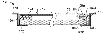
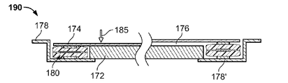
본 발명의 다른 변경예는 EAP 필름 상에서 발생할 수 있는 습기 또는 수분 응축의 임의의 효과를 최소화하기 위한 EAP 액츄에이터의 밀폐식 밀봉을 포함한다. 아래에서 설명되는 다양한 실시양태에 대해, EAP 액츄에이터는 촉각 피드백 장치의 다른 구성요소로부터 실질적으로 분리되어 장벽 필름 내에 밀봉된다. 장벽 필름 또는 케이싱은 밀봉된 필름 내로의 수분의 누출을 최소화하기 위해 바람직하게는 열 밀봉되는 호일 등으로 만들어질 수 있다. 장벽 필름 또는 케이싱의 일부는 케이싱 내부의 액츄에이터의 케이싱 외부의 지점에 대한 개선된 기계적 커플링을 허용하도록 순응성 재료로 만들어질 수 있다. 이러한 장치 실시양태 각각은 밀폐식으로 밀봉된 액츄에이터 패키지 내에서의 임의의 훼손을 최소화하면서, 사용자 입력 표면, 예컨대 키패드의 접촉 표면에 대한 액츄에이터의 출력 부재의 피드백 운동의 커플링을 가능케 한다. 사용자 인터페이스 접촉 표면에 액츄에이터의 운동을 커플링시키기 위한 다양한 예시적인 수단이 또한 제공된다. 방법론에 관하여, 본 방법은 설명된 장치의 사용과 관련된 기구 및/또는 활동 각각을 포함할 수 있다. 이와 같이, 설명된 장치의 사용에 관계된 방법론이 본 발명의 일부를 형성한다. 다른 방법은 그러한 장치의 제작에 초점을 맞출 수 있다.Another variation of the invention involves the hermetic sealing of an EAP actuator to minimize any effects of moisture or moisture condensation that may occur on the EAP film. For the various embodiments described below, the EAP actuator is substantially separated from other components of the haptic feedback device and sealed in the barrier film. The barrier film or casing may be made of a foil or the like which is preferably heat sealed to minimize the leakage of moisture into the sealed film. A portion of the barrier film or casing may be made of a compliant material to allow improved mechanical coupling to a point outside the casing of the actuator inside the casing. Each of these device embodiments enable coupling of the feedback movement of the output member of the actuator to the user input surface, such as the contact surface of the keypad, while minimizing any tampering within the hermetically sealed actuator package. Various exemplary means for coupling the movement of the actuator to the user interface contact surface are also provided. With regard to the methodology, the method may include each of the instruments and / or activities associated with the use of the described apparatus. As such, the methodology involved in the use of the described apparatus forms part of the present invention. Other methods can focus on the fabrication of such a device.
도 14a는 사용자 입력 장치(190)에 커플링된 EAP 액츄에이터(204)의 평면 어레이의 하나의 예를 도시한다. 도시하는 바와 같이, EAP 액츄에이터(204)의 어레이는 스크린(232)의 일부분을 덮고, 스탠드오프(256)를 거쳐 장치(190)의 프레임(234)에 커플링된다. 이러한 변경예에서, 스탠드오프(256)는 액츄에이터(204) 및 스크린(232)의 이동을 위한 클리어런스를 허용한다. 장치(190)의 하나의 변경예에서, 액츄에이터(204)의 어레이는 원하는 용도에 의존하여 사용자 인터페이스 표면 또는 스크린(232) 후방의 복수의 이산된 액츄에이터 또는 액츄에이터의 어레이일 수 있다. 도 14b는 도 14a의 장치(190)의 저면도를 도시한다. 화살표(254)에 의해 도시된 바와 같이, EAP 액츄에이터(204)는 스크린(232)에 대해 수직인 방향으로의 이동에 대안적으로 또는 그와 조합하여 축을 따른 스크린(232)의 이동을 허용할 수 있다.14A shows one example of a planar array of
지금까지 설명된 트랜스듀서/액츄에이터 실시양태는 EAP 트랜스듀서 필름의 활성 영역 (즉, 중첩 전극들을 포함하는 영역) 및 불활성 영역에 커플링된 수동 층(들)을 갖는다. 트랜스듀서/액츄에이터가 또한 강성 출력 구조물을 채용한 경우에, 그러한 구조물은 활성 영역 위에서 상주하는 수동 층의 영역 위에 위치되었다. 아울러, 이러한 실시양태의 활성/활성화 가능 영역은 불활성 영역에 대해 중심에 위치되었다. 본 발명은 다른 트랜스듀서/액츄에이터 구성을 또한 포함한다. 예를 들어, 수동 층(들)은 활성 영역만을 또는 불활성 영역만을 덮을 수 있다. 추가로, EAP 필름의 불활성 영역은 활성 영역에 대해 중심에 위치될 수 있다.The transducer / actuator embodiment described so far has a passive layer (s) coupled to an active region (ie, a region comprising overlapping electrodes) and an inactive region of the EAP transducer film. In case the transducer / actuator also employed a rigid output structure, such structure was located above the area of the passive layer residing above the active area. In addition, the active / activatable regions of this embodiment were centered relative to the inactive region. The invention also includes other transducer / actuator configurations. For example, the passive layer (s) may cover only active regions or only inactive regions. In addition, the inactive region of the EAP film can be centered relative to the active region.
도 15a 및 15b를 참조하면, 본 발명의 일 실시양태에 따른, 전기 에너지를 기계적 에너지로 변환시키기 위한 표면 변형 EAP 액츄에이터(10)의 개략도가 제공된다. 액츄에이터(10)는 얇은 엘라스토머 유전성 중합체 층(14) 및 각각 그의 상부 및 하부 표면의 일부 상에서 유전체(14)에 부착된 상부 및 하부 전극(16a, 16b)을 갖는 EAP 트랜스듀서(12)를 포함한다. 유전체 및 적어도 2개의 전극을 포함하는 트랜스듀서(12)의 부분은 본 명세서에서 활성 영역으로 불린다. 본 발명의 트랜스듀서들 중 임의의 하나는 하나 이상의 활성 영역을 가질 수 있다.15A and 15B, a schematic diagram of a surface modified
전압차가 반대로 대전된 전극(16a, 16b)을 가로질러 인가될 때, 반대 전극들은 서로 끌어당겨서, 그들 사이의 유전성 중합체 층(14)의 부분을 압축시킨다. 전극(16a, 16b)이 (z 축을 따라) 함께 더 가까이 당겨짐에 따라, 이들 사이의 유전체 층(14)의 부분은 그가 (x 및 y 축을 따라) 평면 방향으로 팽창하므로 더 얇아진다. 비압축성 중합체, 즉 응력 하에서 실질적으로 일정한 체적을 갖는 중합체에 대해 또는 프레임 등 내의 다른 압축 가능한 중합체에 대해, 이러한 작용은 활성 영역 (즉, 전극에 의해 덮인 영역) 외부의, 특히 활성 영역의 모서리의 주변부 둘레의, 즉 바로 둘레의 순응성 유전 물질이 (트랜스듀서 필름에 의해 형성된 평면에 대해 직교) 두께 방향으로 평면외로 변위되거나 부풀게 한다. 이러한 부풀음은 유전성 표면 특징부(24a-24d)를 생성한다. 평면외 표면 특징부(24)가 활성 영역에 대해 상대적으로 국소적으로 도시되어 있지만, 평면외 특징부는 도시된 바와 같이 항상 국소화되는 것은 아니다. 몇몇 경우에, 중합체가 예비 스트레인되면, 표면 특징부(24a-24b)는 유전 물질의 불활성 부분의 표면 영역 위에 분포된다.When a voltage difference is applied across the oppositely charged
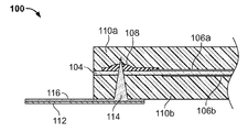
본 트랜스듀서의 표면 특징부의 수직 프로파일 및/또는 가시성을 증폭시키기 위해, 선택적인 수동 층이 트랜스듀서 필름 구조물의 하나 또는 양 면에 추가될 수 있고, 여기서 수동 층은 EAP 필름 표면 영역의 전부 또는 일부분을 덮는다. 도 15a 및 15b의 액츄에이터 실시양태에서, 상부 및 하부 수동 층(18a, 18b)은 EAP 필름(12)의 상부 및 하부 면에 각각 부착된다. 액츄에이터의 활성화 및 유전체 층(12)의 결과적인 표면 특징부(24a-24d)는 도 15b에서 도면 부호(26a-26d)에 의해 표시된 바와 같이, 수동 층(18a, 18b)의 추가된 두께에 의해 증폭된다.To amplify the vertical profile and / or visibility of the surface features of the present transducer, an optional passive layer can be added to one or both sides of the transducer film structure, where the passive layer is all or part of the EAP film surface area. To cover. In the actuator embodiments of FIGS. 15A and 15B, top and bottom
상승된 중합체/수동 층 표면 특징부(26a-26d)에 추가하여, EAP 필름(12)은 하나 또는 양 전극(16a, 16b)이 유전체 층의 두께 아래로 만입되도록 구성될 수 있다. 이와 같이, 만입된 전극 또는 그의 일부는 EAP 필름(12)의 작동 및 유전 물질(14)의 결과적인 변형 시에 전극 표면 특징부를 제공한다. 전극(16a, 16c)은 중합체 표면 특징부, 전극 표면 특징부, 및/또는 수동 층 표면 특징부를 포함할 수 있는 맞춤화형 트랜스듀서 필름 표면 특징부를 생성하도록 패턴화되거나 설계될 수 있다.In addition to the elevated polymer / passive layer surface features 26a-26d, the
도 15a 및 15b의 액츄에이터 실시양태(10)에서, 하나 이상의 구조물(20a, 20b)이 순응성 수동 슬래브와 강성 기계적 구조물 사이에서 작업을 커플링시키고 액츄에이터의 작업 출력을 유도하는 것을 용이하게 하도록 제공된다. 여기서, (플랫폼, 바, 레버, 로드 등의 형태일 수 있는) 상부 구조물(20a)은 출력 부재로서 작용하고, 하부 구조물(20b)은 접지부와 같은 고정되거나 강성인 구조물(22)에 액츄에이터(10)를 커플링시키도록 역할한다. 이러한 출력 구조물은 이산된 구성요소들일 필요가 없고, 액츄에이터가 구동하도록 의도된 구조물과 통합되거나 일체일 수 있다. 구조물(20a, 20b)은 또한 수동 층(18a, 18b)에 의해 형성된 표면 특징부(26a-26d)의 주변부 또는 형상을 형성하도록 역할한다. 도시된 실시양태에서, 집합적 액츄에이터 스택이 도 15b에 도시된 바와 같이, 액츄에이터의 불활성 부분의 두께의 증가를 생성하지만, 작동 시에 액츄에이터가 겪는 높이의 실효 변화(Δh)는 마이너스이다.In the
본 발명의 EAP 트랜스듀서는 원하는 두께 모드 작동을 제공하기 위한 임의의 적합한 구성을 가질 수 있다. 예를 들어, 하나 초과의 EAP 필름 층이 통합된 감지 능력을 갖는 키보드 키와 같은 더 복잡한 용도에서 사용하기 위한 트랜스듀서를 제작하는데 사용될 수 있고, 여기서 추가의 EAP 필름 층이 용량성 센서로서 채용될 수 있다.The EAP transducer of the present invention may have any suitable configuration for providing the desired thickness mode operation. For example, more than one EAP film layer can be used to fabricate transducers for use in more complex applications, such as keyboard keys with integrated sensing capability, where additional EAP film layers can be employed as capacitive sensors. Can be.
도 16a는 본 발명에 따른 이중 EAP 필름 층(34)을 갖는 적층된 트랜스듀서(32)를 채용한 액츄에이터(30)를 도시한다. 이중 층은 2개의 유전성 엘라스토머 필름을 포함하고, 상부 필름(34a)은 각각 상부 및 하부 전극(34b, 34c) 사이에 삽입되고, 하부 필름(36a)은 각각 상부 및 하부 전극(36b, 36c) 사이에 삽입된다. 전도성 트레이스 또는 층(일반적으로, "버스 바(bus bar)"로 불림)의 쌍이 전원의 고전압 측 및 접지 측(도시되지 않음)에 전극을 커플링시키기 위해 제공된다. 버스 바는 각각의 EAP 필름의 "불활성" 부분 (즉, 상부 및 하부 전극들이 중첩하지 않는 부분) 상에 위치된다. 상부 및 하부 버스 바(42a, 42b)는 유전체 층(34a)의 상부 및 하부 면 상에 각각 위치되고, 상부 및 하부 버스 바(44a, 44b)는 유전체 층(36a)의 상부 및 하부 면 상에 각각 위치된다. 유전체(34a)의 상부 전극(34b) 및 유전체(36a)의 하부 전극(36c), 즉 2개의 외향 전극들은 전도성 엘라스토머 비아(via)(68a)(도 16b에 도시됨)를 통한 버스 바(42a, 44a)의 상호 커플링에 의해 공통으로 극성화되고, 비아의 형성은 도 17a-17d에 대해 아래에서 더 상세하게 설명된다. 유전체(34a)의 하부 전극(34c) 및 유전체(36a)의 상부 전극(36b), 즉 2개의 내향 전극들 또한 (도 16b에 도시된) 전도성 엘라스토머 비아(68b)를 통한 버스 바(42b, 44b)의 상호 커플링에 의해 공통으로 극성화된다. 포팅(potting) 재료(66a, 66b)가 비아(68a, 68b)를 밀봉하도록 사용된다. 액츄에이터를 작동시킬 때, 각각의 전극 쌍의 대향 전극들은 전압이 인가되면 함께 당겨진다. 안전을 목적으로, 접지 전극은 임의의 관통 물체를 그가 고전압 전극에 도달하기 전에 접지시켜서 충격 위험을 제거하기 위해 스택의 외부에 위치될 수 있다. 2개의 EAP 필름 층은 필름-필름 접착제(40b)에 의해 함께 접착될 수 있다. 접착 층은 성능을 향상시키기 위한 수동 또는 슬래브 층을 선택적으로 포함할 수 있다. 상부 수동 층 또는 슬래브(50a) 및 하부 수동 층(52b)은 접착 층(40a) 및 접착 층(40c)에 의해 트랜스듀서 구조물에 접착된다. 출력 바(46a, 46b)가 각각 접착 층(48a, 48b)에 의해 상부 및 하부 수동 층에 각각 커플링될 수 있다.16A shows an
본 발명의 액츄에이터는 임의의 적합한 개수의 트랜스듀서 층을 채용할 수 있고, 이때 층의 개수는 짝수 또는 홀수일 수 있다. 홀수의 구성에서, 하나 이상의 공통 접지 전극 및 버스 바가 사용될 수 있다. 추가로, 안전이 문제가 덜 되는 경우에, 고전압 전극은 특정 용도를 더 잘 수용하기 위해 트랜스듀서 스택의 외부에 위치될 수 있다.The actuator of the present invention may employ any suitable number of transducer layers, where the number of layers may be even or odd. In odd configurations, one or more common ground electrodes and bus bars may be used. In addition, where safety is less of a concern, high voltage electrodes can be located outside of the transducer stack to better accommodate a particular application.
작동하기 위해서, 액츄에이터(30)는 전원 및 제어 전자 장치(모두 도시되지 않음)에 전기적으로 커플링되어야 한다. 이는 전원 또는 중간 연결부에 고전압 및 접지 비아(68a, 68b)를 커플링시키는 액츄에이터 또는 PCB 또는 가요성 커넥터(62) 상의 전기 트레이스 또는 와이어에 의해 달성될 수 있다. 액츄에이터(30)는 그를 습도 및 환경 오염물로부터 밀봉하기 위해 보호 장벽 재료 내에 패키징될 수 있다. 여기서, 보호 장벽은 외부 힘 및 스트레인 및/또는 환경 노출로부터 액츄에이터를 보호하기 위해 PCB/가요성 커넥터(62) 둘레에서 바람직하게는 밀봉되는 상부 및 하부 커버(60, 64)를 포함한다. 몇몇 실시양태에서, 보호 장벽은 밀폐성 시일을 제공하도록 불투과성일 수 있다. 커버는 액츄에이터(30)를 물리적 손상에 대해 차폐하기 위한 다소 강성인 형태를 가질 수 있거나, 액츄에이터(30)의 작동 변위를 위한 공간을 허용하도록 순응성일 수 있다. 하나의 구체적인 실시양태에서, 상부 커버(60)는 성형된 호일로 만들어지고, 하부 커버(64)는 순응성 호일로 만들어지며, 그 반대도 가능하고, 2개의 커버는 그 다음 보드/커넥터(62)에 열 밀봉된다. 금속화된 중합체 필름, PVDC, 아클라(Aclar), 스티렌 또는 올레핀계 공중합체, 폴리에스테르 및 폴리올레핀과 같은 많은 다른 패키징 재료가 또한 사용될 수 있다. 순응성 재료는 액츄에이터 출력을 변환시키는 출력 구조물 또는 구조물들, 여기서 바(46b)를 덮도록 사용된다.In order to operate,
방금 설명된 액츄에이터(30)와 같은, 본 발명의 적층된 액츄에이터/트랜스듀서 구조물의 전도성 구성요소/층은 일반적으로 구조물을 통해 형성된 전기 비아(도 16b의 68a, 68b)에 의해 커플링된다. 도 17a-19는 비아를 형성하기 위한 본 발명의 다양한 방법을 도시한다.Conductive components / layers of the stacked actuator / transducer structures of the present invention, such as the
도 16b의 액츄에이터(30) 내에서 채용되는 유형의 전도성 비아의 형성이 도 17a-17d를 참조하여 설명된다. (여기서, 수동 층(78a, 78b) 사이에 집합적으로 삽입된, 유전체 층(74)의 불활성 부분의 대향 면들 상에 위치된 직경 방향으로 위치된 버스 바(76a, 76b)를 갖는 단일 필름 트랜스듀서로부터 구성된) 액츄에이터(70)의 PCB/가요성 커넥터(72)로의 라미네이션 이전 또는 이후에, 적층된 트랜스듀서/액츄에이터 구조물(70)은 도 17b에 도시된 바와 같이, 비아 홀(82a, 82b)을 형성하도록 그의 전체 두께를 통해 PCB(72)까지 레이저 드릴링(80)된다. 기계적 드릴링, 펀칭, 몰딩, 관통, 및 코어링과 같은 비아 홀을 생성하기 위한 다른 방법이 또한 사용될 수 있다. 비아 홀은 그 다음 도 17c에 도시된 바와 같이, 전도성 물질, 예컨대 실리콘 내의 탄소 입자로, 주입에 의한 것과 같은 임의의 적합한 분배 방법에 의해 충전된다. 그 다음, 도 17d에 도시된 바와 같이, 전도성으로 충전된 비아(84a, 84b)는 비아의 노출된 단부를 전기적으로 절연시키기 위해, 임의의 양립 가능한 비전도성 물질, 예컨대 실리콘으로 선택적으로 포팅(86a, 86b)된다. 대안적으로, 비전도성 테이프가 노출된 비아 위에 위치될 수 있다.The formation of conductive vias of the type employed in the
표준 전기 배선이 전원 및 전자 장치에 액츄에이터를 커플링시키기 위해 PCB 또는 가요성 커넥터 대신에 사용될 수 있다. 그러한 실시양태에서 전원으로의 전기 비아 및 전기 연결부를 형성하는 다양한 단계가 도 18a-18d에 도시되어 있고, 도 17a-17d의 것과 유사한 구성요소 및 단계는 동일한 도면 부호를 갖는다. 여기서, 도 18a에 도시된 바와 같이, 비아 홀(82a, 82b)은 버스 바(84a, 84b)가 도달될 정도로 액츄에이터 두께 내의 깊이까지만 드릴링되면 된다. 비아 홀은 그 다음 도 18b에 도시된 바와 같이, 전도성 물질로 충전되고, 그 후에 와이어 리드(88a, 88b)가 도 18c에 도시된 바와 같이, 충진된 전도성 물질 내로 삽입된다. 전도성으로 충전된 비아 및 와이어 리드는 그 다음 도 18d에 도시된 바와 같이, 포팅될 수 있다.Standard electrical wiring can be used in place of a PCB or flexible connector to couple actuators to power sources and electronics. Various steps for forming electrical vias and electrical connections to a power source in such embodiments are shown in FIGS. 18A-18D, and components and steps similar to those of FIGS. 17A-17D have the same reference numerals. Here, as shown in FIG. 18A, the via
도 19는 본 발명의 트랜스듀서 내에 전도성 비아를 제공하는 다른 방법을 도시한다. 트랜스듀서(100)는 전극(106a, 106b) 사이에 삽입되고, 결국 수동 중합체 층(110a, 110b) 사이에 삽입되는 부분을 갖는 유전체 층(104)을 포함하는 유전체 필름을 갖는다. 전도성 버스 바(108)가 EAP 필름의 불활성 영역 상에 제공된다. 관통 구성을 갖는 전도성 접속부(114)가 트랜스듀서의 일 면을 통해 버스 바 재료(108)를 투과하는 깊이까지 수동으로 또는 달리 구동된다. 전도성 트레이스(116)가 관통 접속부(114)의 노출 단부로부터 PCB/가요성 커넥터(112)를 따라 연장한다. 비아를 형성하는 이러한 방법은 비아 홀을 드릴링하는 단계, 비아 홀을 충전하는 단계, 비아 홀 내에 전도성 와이어를 위치시키는 단계, 및 비아 홀을 포팅하는 단계를 제거하므로 특히 효율적이다.19 illustrates another method of providing conductive vias in the transducer of the present invention.
본 발명의 두께 모드 EAP 트랜스듀서는 임의의 적합한 구성 및 표면 특징부 외형을 갖는 다양한 액츄에이터 용도에서 사용 가능하다. 도 20a-24는 예시적인 두께 모드 트랜스듀서/액츄에이터 용도를 도시한다.The thickness mode EAP transducer of the present invention can be used in a variety of actuator applications having any suitable configuration and surface feature geometry. 20A-24 illustrate exemplary thickness mode transducer / actuator applications.
도 20a는 사용자가 장치, 예컨대 키보드, 터치 스크린, 전화 등과 물리적으로 접촉하는 촉각 또는 햅틱 피드백 용도에서 사용하기 위한 버튼 액츄에이터에 대해 이상적인 둥근 구성을 갖는 두께 모드 트랜스듀서(120)를 도시한다. 트랜스듀서(120)는 얇은 엘라스토머 유전성 중합체 층(122) 및 도 20b의 독립된 도면에 가장 잘 도시된 상부 및 하부 전극 패턴(124a, 124b)(하부 전극 패턴은 점선으로 도시됨)으로부터 형성된다. 전극 패턴(124) 각각은 동심 패턴을 형성하는 복수의 대향하여 연장하는 핑거 부분(127)을 갖는 스템 부분(125)을 제공한다. 2개의 전극의 스템은 둥근 유전체 층(122)의 대향 측 상에서 서로에 대해 직경 방향으로 위치되고, 여기서 그들 각각의 핑거 부분들은 도 20a에 도시된 패턴을 생성하도록 서로 병치 정렬된다. 이러한 실시양태의 대향 전극 패턴들이 동일하며 서로 대칭이지만, 대향 전극 패턴들이 형상 및/또는 그들이 점유하는 표면적의 양에 있어서, 비대칭인 다른 실시양태가 고려된다. 2개의 전극 재료가 중첩하지 않는 트랜스듀서 재료의 부분은 트랜스듀서의 불활성 부분(128a, 128b)을 형성한다. 전기 접속부(126a, 126b)가 전원 및 제어 전자 장치(모두 도시되지 않음)에 트랜스듀서를 전기적으로 커플링시키기 위해 2개의 전극 스템 부분 각각의 기부에 제공된다. 트랜스듀서가 활성화될 때, 대향하는 전극 핑거들이 함께 당겨져서, 그들 사이의 유전 물질(122)을 압축시키고, 트랜스듀서의 불활성 부분(128a, 128b)은 필요하다면 버튼의 주변부 둘레에 및/또는 버튼 내부에 표면 특징부를 형성하도록 부푼다.20A illustrates a
버튼 액츄에이터는 단일 입력 또는 접촉 표면 형태일 수 있거나, 복수의 접촉 표면을 갖는 어레이 형식으로 제공될 수 있다. 어레이 형태로 구성될 때, 도 20a의 버튼 트랜스듀서는 다양한 사용자 인터페이스 장치, 예컨대 컴퓨터 키보드, 전화, 계산기 등을 위한, 도 21에 도시된 바와 같은 키패드 액츄에이터(130) 내에서 사용하기에 이상적이다. 트랜스듀서 어레이(132)는 상호 연결된 전극 패턴의 상부 어레이(136a) 및 전극 패턴의 (점선으로 도시된) 하부 어레이(136b)를 포함하고, 2개의 어레이는 서로 대향하여, 설명된 바와 같은 활성 및 불활성 부분을 갖는 도 20a의 동심 트랜스듀서 패턴을 생성한다. 키보드 구조물은 트랜스듀서 어레이(132) 위의 수동 층(134) 형태일 수 있다. 수동 층(134)은 사용자가 그의 손가락을 개별 키패드와 촉각적으로 정렬시키는 것을 가능케 하고/거나 활성화 시에 각각의 버튼의 주변부의 부풀음을 추가로 증폭시키기 위해 수동 상태에서 상승될 수 있는, 키 경계부(138)와 같은 그 자신의 표면 특징부를 가질 수 있다. 키가 눌리면, 키가 놓여 있는 개별 트랜스듀서가 활성화되어, 위에서 설명된 바와 같이 두께 모드 부풀음을 일으켜서, 사용자에게 촉각적 감각을 제공한다. 임의의 개수의 트랜스듀서가 이러한 방식으로 제공되고 사용되는 키패드(134)의 유형 및 크기를 수용하도록 이격될 수 있다. 그러한 트랜스듀서 어레이에 대한 제작 기술의 예가 발명의 명칭이 "ELECTROACTIVE POLYMER TRANSDUCERS FOR SENSORY FEEDBACK APPLICATIONS"인 2008년 6월 27일자로 출원된 미국 특허 출원 제12/163,554호에 개시되어 있고, 이의 전문은 본원에 참고로 포함된다. The button actuators may be in the form of a single input or contact surface, or may be provided in an array with a plurality of contact surfaces. When configured in an array, the button transducer of FIG. 20A is ideal for use within
본 기술 분야의 당업자는 본 발명의 두께 모드 트랜스듀서가 대칭일 필요가 없고 임의의 구성 및 형상을 취할 수 있음을 이해할 것이다. 본 트랜스듀서는 도 22에 도시된 신규한 손 장치(140)와 같은, 임의의 상상할 수 있는 신규한 용도에서 사용될 수 있다. 유사한 손 형상의 상부 및 하부 전극 패턴(144a, 144b)(저면 패턴은 점선으로 도시됨)을 갖는 사람 손 형태의 유전 물질(142)이 제공된다. 전극 패턴 각각은 각각 버스 바(146a, 146b)에 전기적으로 커플링되고, 이는 결국 전원 및 제어 전자 장치(모두 도시되지 않음)에 전기적으로 커플링된다. 여기서, 대향하는 전극 패턴들은 서로 끼워지기보다는 서로 정렬되거나 중첩되고, 이에 의해 교대하는 활성 및 불활성 영역을 생성한다. 이와 같이, 전반적으로 패턴의 내부 및 외부 모서리 상에서만 상승된 표면 특징부를 생성하는 대신에, 상승된 표면 특징부는 손 프로파일 전체에 걸쳐, 즉 불활성 영역 상에 제공된다. 이러한 예시적인 용도의 표면 특징부는 촉각 피드백보다는 시각 피드백을 제공할 수 있음을 알아야 한다. 시각 피드백은 착색, 반사 재료 등에 의해 향상될 수 있음이 고려된다.Those skilled in the art will understand that the thickness mode transducer of the present invention need not be symmetrical and can take any configuration and shape. The transducer may be used in any conceivable novel application, such as the
본 발명의 트랜스듀서 필름은 특히 트랜스듀서 전극 패턴이 균일하거나 반복되는 경우에, 일반적으로 사용되는 웹-기반 제조 기술에 의해, 효율적으로 대량 생산될 수 있다. 도 23에 도시된 바와 같이, 트랜스듀서 필름(150)은 유전 물질(152)의 스트립 상에 침착되거나 형성된 연속적인 상부 및 하부 전기 버스(156a, 156b)를 갖는 연속적인 스트립 형식으로 제공될 수 있다. 더 전형적으로, 두께 모드 특징부는 각각의 버스 바(156a, 156b)에 전기적으로 커플링된 상부 및 하부 전극 패턴(154a, 154b)에 의해 형성된 이산되지만 (즉, 연속적이지 않지만) 반복되는 활성 영역(158)에 의해 형성되고; 그의 크기, 길이, 형상, 및 패턴은 특정 용도에 대해 맞춤화될 수 있다. 그러나, 활성 영역(들)이 연속적인 패턴으로 제공될 수 있음이 고려된다. 전극 및 버스 패턴은 공지된 웹-기반 제조 기술에 의해 형성될 수 있고, 개별 트랜스듀서는 그 다음 선택된 단일화 라인(155)을 따라 스트립(150)을 절단하는 것과 같은 공지된 기술에 의해 단일화된다. 활성 영역이 스트립을 따라 연속적으로 제공되는 경우에, 스트립은 전극을 단락시키는 것을 회피하기 위해 고도의 정밀도로 절단되도록 요구됨을 알아야 한다. 이러한 전극의 절단 단부는 포팅을 요구할 수 있거나, 트래킹(tracking) 문제를 회피하기 위해 에칭될 수 있다. 버스(156a, 156b)의 절단된 단자는 그 다음 결과적인 액츄에이터의 작동을 가능케 하도록 전원/제어부에 커플링된다.The transducer film of the present invention can be efficiently mass-produced by the commonly used web-based manufacturing technique, especially when the transducer electrode pattern is uniform or repeated. As shown in FIG. 23, the
단일화 이전 또는 이후에, 스트립 또는 단일화된 스트립 부분은 다층 구조를 제공하도록 임의의 개수의 다른 트랜스듀서 필름 스트립/스트립 부분과 함께 적층될 수 있다. 적층된 구조물은 그 다음 출력 바 등과 같은, 액츄에이터의 강성 기계적 구성요소에, 필요하다면, 라미네이팅되고 기계적으로 커플링될 수 있다.Before or after unification, the strip or unified strip portions may be laminated with any number of other transducer film strips / strip portions to provide a multilayer structure. The laminated structure can then be laminated and mechanically coupled, if necessary, to the rigid mechanical component of the actuator, such as an output bar or the like.
도 24는 본 트랜스듀서의 다른 변경예를 도시하고, 여기서 트랜스듀서(160)는 스트립의 대향 면들 상의 상부 및 하부 전극(164a, 164b)이 직사각형 패턴으로 배열되어 개방 영역(165)을 에워싸는, 유전 물질(162)의 스트립에 의해 형성된다. 전극 각각은 전원 및 제어 전자 장치(모두 도시되지 않음)에 커플링하기 위한 전기 접점(168a, 168b)을 갖는 전기 버스(166a, 166b) 내에서 각각 종결된다. 둘러싸인 영역(165)을 가로질러 연장하는 수동 층(도시되지 않음)이 트랜스듀서 필름의 각 면 상에 채용될 수 있어서, 출력 바(도시되지 않음)의 환경적 보호 및 기계적 커플링을 위한 가스켓 구성을 형성한다. 구성된 바와 같이, 트랜스듀서의 활성화는 트랜스듀서 스트립의 내부 및 외부 주변부(169)를 따른 표면 특징부 및 활성 영역(164a, 164b)의 두께 감소를 생성한다. 가스켓 액츄에이터는 연속적인 단일 액츄에이터일 필요가 없음을 알아야 한다. 하나 이상의 이산된 액츄에이터가 또한 비-활성 순응성 가스켓 재료로 선택적으로 밀봉될 수 있는 영역의 주변부를 라이닝하도록 사용될 수 있다.FIG. 24 shows another variation of the present transducer, where transducer 160 is a dielectric, in which top and
다른 가스켓형 액츄에이터가 위에서 참조된 미국 특허 출원 제12/163,554호에 개시되어 있다. 이러한 유형의 액츄에이터는 휴대형 멀티미디어 장치, 의료용 기기, 키오스크 또는 자동차 계기판, 완구 및 다른 신규한 제품 등 내에서의 용도를 위한 터치 센서 플레이트, 터치 패드 및 터치 스크린과 같은 감각 (예컨대, 햅틱 또는 진동) 피드백 용도에 대해 적합하다.Another gasketed actuator is disclosed in US patent application Ser. No. 12 / 163,554, referenced above. Actuators of this type are sensory (eg, haptic or vibrational) feedback such as touch sensor plates, touch pads, and touch screens for use in portable multimedia devices, medical devices, kiosks or automotive dashboards, toys, and other new products. It is suitable for use.
도 25a-25d는 본 발명의 두께 모드 액츄에이터의 변경예를 채용한 터치 스크린의 단면도이고, 유사한 도면 부호가 4개의 도면에 걸쳐 유사한 구성요소를 표시한다. 도 25a를 참조하면, 터치 스크린 장치(170)는 전형적으로 유리 또는 플라스틱 재료로 만들어진 터치 센서 플레이트(174), 및 선택적으로 액정 디스플레이(LCD)(172)를 포함할 수 있다. 둘은 함께 적층되고, 그들 사이에 개방 공간(176)을 형성하는 EAP 두께 모드 액츄에이터(180)에 의해 이격된다. 집합적인 적층된 구조물은 프레임(178)에 의해 함께 유지된다. 액츄에이터(180)는 전극 쌍(184a, 184b)에 의해 중심에 삽입된 유전체 필름 층(182)에 의해 형성된 트랜스듀서 필름을 포함한다. 트랜스듀서 필름은 결국 상부 및 하부 수동 층(186a, 186b) 사이에 삽입되고, 아울러 터치 플레이트(174) 및 LCD(172)에 각각 기계적으로 커플링된 한 쌍의 출력 구조물(188a, 188b) 사이에 유지된다. 도 25a의 우측은 액츄에이터가 불활성일 때의 LCD와 터치 플레이트의 상대 위치를 도시하고, 도 25a의 좌측은 액츄에이터가 활성일 때, 즉 사용자가 화살표(175)의 방향으로 터치 플레이트(174)를 눌렀을 때의 구성요소들의 상대 위치를 도시한다. 도면의 좌측으로부터 명백한 바와 같이, 액츄에이터(180)가 활성화될 때, 전극(184a, 184b)은 함께 당겨져서, 그들 사이의 유전체 필름(182)의 부분을 압축시키며 활성 영역 외부에서 유전 물질 및 수동 층(186a, 186b) 내에 표면 특징부를 생성하고, 표면 특징부는 출력 블록(188a, 188b)에 기인한 압축력에 의해 추가로 향상된다. 이와 같이, 표면 특징부는 터치 플레이트를 누르는 것에 응답하여 촉각적 감각을 사용자에게 제공하는 화살표(175)와 반대 방향으로 터치 플레이트(174) 상에 약간의 힘을 제공한다.25A-25D are cross-sectional views of a touch screen employing a variation of the thickness mode actuator of the present invention, wherein like reference numerals denote similar components throughout the four views. Referring to FIG. 25A, the
도 25b의 터치 스크린 장치(190)는 도 25a와 유사한 구성을 갖고, 차이점은 LCD(172)는 전체가 직사각형 (또는 정사각형 등) 형상의 두께 모드 액츄에이터(180)에 의해 에워싸인 내부 영역 내에 존재하는 것이다. 이와 같이, (도면의 우측에 도시되어 있는 바와 같이) 장치가 불활성 상태일 때의 LCD(172)와 터치 플레이트(174) 사이의 간격(176)은 도 25a의 실시양태보다 상당히 더 작아서, 더 낮은 프로파일의 설계를 제공한다. 아울러, 액츄에이터의 하부 출력 구조물(188b)은 프레임(178)의 후방 벽(178') 상에 직접 놓인다. 2개의 실시양태 사이의 구조적 차이점에 관계없이, 장치(190)는 액츄에이터 표면 특징부가 터치 플레이트를 누르는 것에 응답하여 화살표(185)와 반대 방향으로 약간의 촉각적 힘을 제공하는 점에서 장치(170)와 유사하게 기능한다.The
방금 설명된 2개의 터치 스크린 장치는 그들이 단일 방향으로 기능하므로 단상 장치이다. 본 가스켓형 액츄에이터 중 둘 (또는 그 이상)이 도 25c에서와 같이 2상 (2방향성) 터치 스크린 장치(200)를 생성하도록 나란히 사용될 수 있다. 장치(200)의 구성은 도 25b의 장치와 유사하지만, 터치 플레이트(174) 위에 놓이는 제2 두께 모드 액츄에이터(180')가 추가된다. 2개의 액츄에이터 및 터치 플레이트(174)는 추가된 내측으로 연장하는 상부 견부(178")를 갖는 프레임(178)에 의해 적층된 관계로 유지된다. 이와 같이, 터치 플레이트(174)는 각각 액츄에이터(180, 180')의 최내측 출력 블록(188a, 188b') 사이에 직접 삽입되고, 액츄에이터(180')의 최외측 출력 블록(188b, 188a')은 각각 프레임 부재(178', 178")를 지지한다. 이러한 둘러싸인 가스켓 배열은 공간(176) 내의 광학 경로를 먼지 및 찌꺼기가 없게 유지한다. 여기서, 도면의 좌측은 활성 상태의 하부 액츄에이터(180) 및 수동 상태의 상부 액츄에이터(180')를 도시하고, 이때 센서 플레이트(174)는 화살표(195)의 방향으로 LCD(172)를 향해 이동하게 된다. 역으로, 도면의 우측은 수동 상태의 하부 액츄에이터(180) 및 활성 상태의 상부 액츄에이터(180')를 도시하고, 이때 센서 플레이트(174)는 화살표(195')의 방향으로 LCD(172)로부터 멀리 이동하게 된다.The two touch screen devices just described are single phase devices because they function in a single direction. Two (or more) of the present gasketed actuators may be used side by side to create a two-phase (bidirectional)
도 25d는 전극이 터치 센서 플레이트에 대해 직교 배향되어 있는 한 쌍의 두께 모드 스트립 액츄에이터(180)를 갖는 다른 2상 터치 센서 장치(210)를 도시한다. 여기서, 터치 플레이트(174)의 2상 또는 2방향성 이동은 화살표(205)에 의해 표시된 바와 같이 평면내이다. 그러한 평면내 운동을 가능케 하기 위해, 액츄에이터(180)는 그의 EAP 필름의 평면이 LCD(172) 및 터치 플레이트(174)에 대해 직교되도록 위치된다. 그러한 위치를 유지하기 위해, 액츄에이터(180)는 프레임(178)의 측벽(202)과 터치 플레이트(174)가 놓이는 내측 프레임 부재(206) 사이에 유지된다. 내측 프레임 부재(206)가 액츄에이터(180)의 출력 블록(188a)에 고정되지만, 터치 플레이트(174)는 평면내 또는 측방 운동을 허용하도록 외측 프레임(178)에 대해 "부유"한다. 이러한 구성은 터치 플레이트(174)에 의한 2상 평면외 운동에 대해 필수적인 추가된 클리어런스를 제거하므로, 상대적으로 콤팩트하고 낮은 프로파일의 설계를 제공한다. 2개의 액츄에이터는 2상 운동을 위해 반대로 작동한다. 플레이트(174) 및 브라켓(206)의 조합된 어셈블리는 액츄에이터 스트립(180)을 프레임(178)의 측벽(202)에 대해 약간 압축되게 유지한다. 하나의 액츄에이터가 활성일 때, 그는 추가로 압축되거나 얇아지고, 다른 액츄에이터는 저장된 압축력으로 인해 팽창한다. 이는 플레이트 어셈블리를 활성 액츄에이터를 향해 이동시킨다. 플레이트는 제1 액츄에이터를 탈활성화하고 제2 액츄에이터를 활성화함으로써 반대 방향으로 이동한다.25D shows another two-phase
도 26a 및 26b는 트랜스듀서의 불활성 영역이 활성 영역(들)에 대해 내부에 또는 중심에 위치되는, 즉 EAP 필름의 중심 부분에 중첩 전극들이 없는 변경예를 도시한다. 두께 모드 액츄에이터(360)는 필름의 중심 부분(365)이 수동이며 전극 재료가 없는, 전극 층(364a, 364b) 사이에 삽입된 유전 물질(362)을 포함하는 EAP 트랜스듀서 필름을 포함한다. EAP 필름은 집합적으로 카트리지 구성을 제공하는 상부 및 하부 프레임 부재(366a, 366b) 중 적어도 하나에 의해 긴장되거나 연신된 상태로 유지된다. 필름의 수동 부분(365)의 상부 및 하부 면 중 적어도 하나를 덮는 것은 각각 그 위에 장착된 선택적인 강성 구속물 또는 출력 부재(370a, 370b)를 갖는 수동 층(368a, 368b)이다. EAP 필름이 카트리지 프레임(366)에 의해 그의 주변부에서 구속되면, 활성화될 때 (도 26b 참조), EAP 필름의 압축은 전술한 액츄에이터 실시양태에서와 같이 외측으로가 아닌, 화살표(367a, 367b)에 의해 도시된 바와 같이, 필름 재료가 내측으로 수축하게 한다. 압축된 EAP 필름은 수동 재료(368a, 368b) 상에 충돌하여, 그의 직경이 감소하고 그의 높이가 증가하게 한다. 구성의 이러한 변화는 각각 출력 부재(370a, 370b) 상에 외향력을 적용한다. 앞서 설명된 액츄에이터 실시양태에서와 같이, 수동으로 커플링된 필름 액츄에이터들은 다중상 작동을 제공하고/거나 액츄에이터의 출력 힘 및/또는 스트로크를 증가시키도록, 적층되거나 평탄한 관계로 복수로 제공될 수 있다.26A and 26B show a variation in which the inactive region of the transducer is located internally or centered relative to the active region (s), ie there are no overlapping electrodes in the central portion of the EAP film. The
성능은 유전체 필름 및/또는 수동 재료를 예비 스트레인시킴으로써 향상될 수 있다. 액츄에이터는 키 또는 버튼 장치로서 사용될 수 있고, 멤브레인 스위치와 같은 센서 장치와 적층 또는 통합될 수 있다. 하부 출력 부재 또는 하부 전극은 회로를 완성하기 위해 멤브레인 스위치에 충분한 압력을 제공하도록 사용될 수 있거나, 하부 출력 부재가 전도성 층을 가지면 회로를 직접 완성할 수 있다. 다중 액츄에이터가 키패드 또는 키보드와 같은 용도에 대해 어레이로 사용될 수 있다.Performance can be improved by prestraining the dielectric film and / or passive material. The actuator can be used as a key or button device and can be stacked or integrated with a sensor device such as a membrane switch. The bottom output member or bottom electrode can be used to provide sufficient pressure to the membrane switch to complete the circuit, or can directly complete the circuit if the bottom output member has a conductive layer. Multiple actuators can be used in an array for applications such as keypads or keyboards.
미국 특허 출원 공개 제2005/0157893호에 개시되어 있는 다양한 유전성 엘라스토머 및 전극 재료가 본 발명의 두께 모드 트랜스듀서와 함께 사용하기에 적합하다. 대체로, 유전성 엘라스토머는 정전기 힘에 응답하여 변형되거나 변형이 전기장의 변화를 일으키는, 실리콘 고무 및 아크릴과 같은, 임의의 실질적으로 절연성인, 순응성 중합체를 포함한다. 적절한 중합체를 설계 또는 선택하는데 있어서, 최적의 재료, 물리적 및 화학적 특성을 고려할 수 있다. 그러한 특성은 (임의의 측쇄를 포함한) 단량체, 첨가제, 가교 커플링 정도, 결정성, 분자량 등의 신중한 선택에 의해 맞춰질 수 있다.Various dielectric elastomers and electrode materials disclosed in US Patent Application Publication No. 2005/0157893 are suitable for use with the thickness mode transducer of the present invention. In general, dielectric elastomers include any substantially insulating, compliant polymer, such as silicone rubber and acrylic, which deform in response to electrostatic forces or where the deformation causes a change in electric field. In designing or selecting suitable polymers, optimal material, physical and chemical properties can be considered. Such properties can be tailored by careful selection of monomers (including optional side chains), additives, degree of crosslinking coupling, crystallinity, molecular weight and the like.
상기 미국 특허 출원 공개에서 설명되고 사용하기에 적합한 전극은 금속 트레이스 및 전하 분배 층, 조직화된 전극, 탄소 그리스 또는 은 그리스와 같은 전도성 그리스, 콜로이드성 현탁액, 전도성 카본블랙과 같은 높은 종횡비의 전도성 물질, 탄소 섬유, 탄소 나노튜브, 그래핀(graphene) 및 금속 나노와이어, 및 이온 전도성 물질들의 혼합물을 포함하는 구조화된 전극을 포함한다. 전극은 탄소 또는 다른 전도성 입자를 함유하는 엘라스토머 매트릭스와 같은 순응성 재료로 만들어질 수 있다. 본 발명은 또한 금속 및 반강성 전극을 채용할 수 있다.Suitable electrodes for use and described in the US patent application publications include metal trace and charge distribution layers, organized electrodes, conductive greases such as carbon grease or silver grease, colloidal suspensions, high aspect ratio conductive materials such as conductive carbon black, Structured electrodes comprising carbon fibers, carbon nanotubes, graphene and metal nanowires, and mixtures of ionically conductive materials. The electrode can be made of a compliant material, such as an elastomeric matrix containing carbon or other conductive particles. The present invention may also employ metal and semi-rigid electrodes.
본 트랜스듀서 내에서 사용하기 위한 예시적인 수동 층 재료는 예를 들어, 실리콘, 스티렌계 또는 올레핀계 공중합체, 폴리우레탄, 아크릴레이트, 고무, 연질 중합체, 연질 엘라스토머 (겔), 연질 중합체 발포체, 또는 중합체/겔 하이브리드를 포함하지만 이들로 제한되지 않는다. 수동 층(들) 및 유전체 층의 상대 탄성 및 두께는 원하는 출력 (예컨대, 의도된 표면 특징부의 실효 두꺼움 또는 얇음)을 달성하도록 선택되고, 그러한 출력 응답은 선형 (예컨대, 수동 층 두께가 활성화될 때의 유전체 층의 두께에 비례하여 증폭됨) 또는 비선형 (예컨대, 수동 및 유전체 층들이 가변 비율로 얇아지거나 두꺼워짐)이 되도록 설계될 수 있다.Exemplary passive layer materials for use in the present transducers are, for example, silicone, styrenic or olefinic copolymers, polyurethanes, acrylates, rubbers, soft polymers, soft elastomers (gels), soft polymer foams, or Polymer / gel hybrids, but are not limited to these. The relative elasticity and thickness of the passive layer (s) and dielectric layer are selected to achieve the desired output (eg, effective thick or thin of the intended surface feature), and such output response is linear (eg, when passive layer thickness is activated). Amplified in proportion to the thickness of the dielectric layer) or nonlinear (eg, passive and dielectric layers are thinned or thickened at variable rates).
방법론에 관하여, 본 방법은 설명된 장치의 사용과 관련된 기구 및/또는 활동 각각을 포함한다. 이와 같이, 설명된 장치의 사용에 관계된 방법론이 본 발명의 일부를 형성한다. 다른 방법은 그러한 장치의 제작에 초점을 맞출 수 있다.With regard to the methodology, the method includes each of the instruments and / or activities associated with the use of the described apparatus. As such, the methodology involved in the use of the described apparatus forms part of the present invention. Other methods can focus on the fabrication of such a device.
본 발명의 다른 세부 사항에 관하여, 재료 및 대안적인 관련 구성은 관련 기술 분야의 당업자의 수준 내에서 채용될 수 있다. 이는 일반적으로 또는 논리적으로 채용되는 바와 같이 추가의 작용의 측면에서 본 발명의 방법에 기초한 태양에 대해 유효할 수 있다. 또한, 본 발명이 다양한 특징을 선택적으로 포함하는 여러 예를 참조하여 설명되었지만, 본 발명은 본 발명의 각각의 변경예에 대해 고려되는 것으로 설명되거나 표시된 것으로 제한되어서는 안된다. 다양한 변화가 설명된 본 발명에 대해 이루어질 수 있고, (본 명세서에서 언급되었든지 또는 간단하게 하기 위해 포함되지 않았든지 간에) 등가물이 본 발명의 진정한 사상 및 범주로부터 벗어남이 없이 대체될 수 있다. 도시된 임의의 개수의 개별 부품 또는 하위 어셈블리가 그들의 설계에 있어서 통합될 수 있다. 그러한 변화 등은 조립을 위한 설계의 원리에 의해 취해지거나 안내될 수 있다.With respect to other details of the invention, materials and alternative related configurations may be employed within the level of those skilled in the art. This may be valid for aspects based on the methods of the present invention in terms of further action as generally or logically employed. In addition, while the present invention has been described with reference to various examples that optionally include various features, the present invention should not be limited to what has been described or indicated as being considered for each variation of the invention. Various changes may be made to the described invention, and equivalents (whether referred to herein or not included for the sake of simplicity) may be substituted without departing from the true spirit and scope of the invention. Any number of individual parts or subassemblies shown may be integrated in their design. Such changes and the like can be taken or guided by the principles of the design for assembly.
다른 변경예에서, 카트리지 어셈블리 또는 액츄에이터(360)는 진동 버튼, 키, 터치패드, 마우스, 또는 다른 인터페이스 내에서 햅틱 응답을 제공하는데 사용하기에 적합할 수 있다. 그러한 예에서, 액츄에이터(360)의 커플링은 비압축성 출력 기하학적 형상부를 채용한다. 이러한 변경예는 출력 기하학적 형상부 내로 성형된 비압축성 재료를 사용함으로써 전기활성 중합체 다이어프램 카트리지의 결합된 중심 구속물의 대안을 제공한다.In other variations, the cartridge assembly or
중심 디스크가 없는 전기활성 중합체 액츄에이터에서, 작동은 전극 기하학적 형상부의 중심 내의 수동 필름의 상태를 변화시켜서, 응력 및 스트레인(힘 및 변위)을 감소시킨다. 이러한 감소는 단일 방향뿐만 아니라, 필름의 평면 내의 모든 방향에서 발생한다. 전기활성 중합체의 방전 시에, 수동 필름은 그 다음 원래의 응력 및 스트레인 에너지 상태로 복귀한다. 전기활성 중합체 액츄에이터는 비압축성 재료(응력 하에서 실질적으로 일정한 체적을 갖는 것)로 구성될 수 있다. 액츄에이터(360)는 불활성 영역(365) 내의 액츄에이터(360)의 중심에서 수동 필름 영역에 결합된 비압축성 출력 패드(368a, 368b)와 함께 조립되어, 중심 디스크를 대체한다. 이러한 구성은 출력 패드를 수동 부분(365)과의 그의 경계에서 압축시킴으로써 에너지를 전달하도록 사용될 수 있다. 이는 출력 패드(368a, 368b)를 부풀게 하여, 편평 필름에 대해 직교 방향으로의 작동을 생성한다. 비압축성 기하학적 형상부는 작동 중에 그의 변화의 배향을 제어하기 위해 다양한 표면에 구속물을 추가함으로써 추가로 향상될 수 있다. 상기 예에 대해, 출력 패드의 상부 표면을 구속하기 위한 비순응성 강성화재를 추가하는 것은 그러한 표면이 그의 치수를 변화시키는 것을 방지하여, 출력 패드의 원하는 치수에 대한 기하학적 변화에 초점을 맞춘다.In electroactive polymer actuators without a center disk, operation changes the state of the passive film in the center of the electrode geometry, thereby reducing stress and strain (forces and displacements). This reduction occurs not only in a single direction, but in all directions in the plane of the film. Upon discharge of the electroactive polymer, the passive film then returns to its original stress and strain energy state. The electroactive polymer actuator can be composed of an incompressible material (having a substantially constant volume under stress).
위에서 설명된 변경예는 또한 작동 시에 전기활성 중합체 유전성 엘라스토머의 2축 응력 및 스트레인 상태 변화의 커플링; 작동 방향에 대해 직교인 전달 작동; 성능을 최적화하기 위한 비압축성 기하학적 형상부의 설계를 허용할 수 있다. 위에서 설명된 변경예는 임의의 햅틱 피드백 (마우스, 제어기, 스크린, 패드, 버튼, 키보드 등)에 대해 다이어프램, 평면, 관성 구동, 두께 모드, 하이브리드 (첨부된 발명에 설명되어 있는 평면 및 두께 모드의 조합), 및 롤을 포함한 다양한 트랜스듀서 플랫폼을 포함할 수 있다. 이러한 변경예는 사용자 인터페이스 표면, 예컨대 터치 스크린, 키패드, 버튼 또는 키 캡의 특정 부분을 이동시키거나, 전체 장치를 이동시킬 수 있다.Modifications described above also include coupling of biaxial stress and strain state changes of the electroactive polymer dielectric elastomer in operation; Transfer operation orthogonal to the direction of operation; It may allow the design of incompressible geometries to optimize performance. The above-described modifications include diaphragm, plane, inertial drive, thickness mode, and hybrid (plane and thickness modes described in the attached invention) for any haptic feedback (mouse, controller, screen, pad, button, keyboard, etc.). Combinations), and various transducer platforms, including rolls. Such modifications may move certain portions of the user interface surface, such as touch screens, keypads, buttons or keycaps, or may move the entire device.
상이한 장치 구현예들이 상이한 EAP 플랫폼을 요구할 수 있다. 예를 들어, 하나의 예에서, 두께 모드 액츄에이터의 스트립은 키보드 상의 버튼에 대해 키 클릭 감각을 제공하기 위한 터치 스크린, 하이브리드 또는 평면 액츄에이터에 대한 평면외 운동, 또는 마우스 및 제어기 내에서 럼블러(rumbler) 피드백을 제공하기 위한 관성 구동 설계를 제공할 수 있다.Different device implementations may require different EAP platforms. For example, in one example, a strip of thickness mode actuator may be a touch screen to provide key click sensation for a button on a keyboard, an out-of-plane motion for a hybrid or planar actuator, or a rumbler in a mouse and controller. Provide an inertial drive design to provide feedback.
도 27a는 다양한 사용자 인터페이스 장치에 햅틱 피드백을 제공하기 위한 트랜스듀서의 다른 변경예를 도시한다. 이러한 변경예에서, 질량체 또는 중량체(262)가 전기활성 중합체 액츄에이터(30)에 커플링된다. 도시된 중합체 액츄에이터가 필름 카트리지 액츄에이터를 포함하지만, 장치의 대안적인 변경예는 위에서 개시된 EAP 특허 및 출원에 설명되어 있는 바와 같은 스프링 편위식 액츄에이터를 채용할 수 있다.27A illustrates another variation of the transducer for providing haptic feedback to various user interface devices. In this variation, mass or
도 27b는 도 27a의 트랜스듀서 어셈블리의 분해도를 도시한다. 도시된 바와 같이, 관성 트랜스듀서 어셈블리(260)는 2개의 액츄에이터(30) 사이에 삽입된 질량체(262)를 포함한다. 그러나, 장치의 변경예는 질량체의 각 면 상에서 의도된 용도에 의존하여 하나 이상의 액츄에이터를 포함한다. 도시된 바와 같이, 액츄에이터(들)은 관성 질량체(262)에 커플링되고, 기부 플레이트 또는 플랜지에 의해 고정된다. 액츄에이터(30)의 작동은 액츄에이터에 대한 x-y 배향으로의 질량체의 이동을 일으킨다. 추가의 변경예에서, 액츄에이터는 질량체(262)의 수직 또는 z 축 이동을 제공하도록 구성될 수 있다.FIG. 27B shows an exploded view of the transducer assembly of FIG. 27A. As shown, the
도 27c는 도 27a의 관성 트랜스듀서 어셈블리(260)의 측면도를 도시한다. 이러한 도면에서, 어셈블리는 액츄에이터(30) 및 관성 질량체(262)를 둘러싸는 중심 하우징(266) 및 상부 하우징(268)을 갖는 것으로 도시되어 있다. 또한, 어셈블리(260)는 하우징 및 액츄에이터 내의 개방부 또는 비아(24)를 통해 연장하는 고정 수단 또는 체결구(270)를 갖는 것으로 도시되어 있다. 비아(24)는 복수의 기능을 수행할 수 있다. 예를 들어, 비아는 장착만을 목적으로 할 수 있다. 대안적으로 또는 조합하여, 비아는 회로 보드, 가요성 회로 또는 기계적 접지부에 액츄에이터를 전기적으로 커플링시킬 수 있다. 도 27d는 도 27c의 관성 트랜스듀서 어셈블리(260)의 사시도를 도시하고, 여기서 관성 질량체(도시되지 않음)는 하우징 어셈블리(264, 266, 268) 내에 위치된다. 하우징 어셈블리의 부품들은 복수의 기능을 수행할 수 있다. 예를 들어, 기계적 지지부 및 장착 및 부착 특징부를 제공하는 것에 추가하여, 부품은 액츄에이터 카트리지를 손상시킬 수 있는 x, y, 및/또는 z 방향으로의 관성 질량체의 과도한 운동을 방지하기 위한 기계적 멈춤부로서 역할하는 특징부를 포함할 수 있다. 예를 들어, 하우징은 관성 질량체의 과도한 이동을 제한하기 위한 상승된 표면을 포함할 수 있다. 도시된 예에서, 상승된 표면은 비아(24)를 포함하는 하우징의 부분을 포함할 수 있다. 대안적으로, 비아(24)는 그를 통해 위치된 임의의 체결구(270)가 관성 질량체의 이동을 제한하기 위한 효과적인 멈춤부로서 기능하도록 선택적으로 위치될 수 있다.FIG. 27C shows a side view of the
하우징 어셈블리(264, 266)는 또한 취급 시에 전기적 충격을 방지하기 위해 액츄에이터의 모서리를 덮는 통합된 립(lip) 또는 연장부를 구비하여 설계될 수 있다. 이러한 부품들 중 임의의 하나 또는 전부가 또한 소비자 전자 장치의 하우징과 같은 더 큰 어셈블리의 하우징의 일부로서 통합될 수 있다. 예를 들어, 도시된 하우징이 사용자 인터페이스 장치 내에 고정되는 분리된 구성요소로서 도시되어 있지만, 트랜스듀서의 대안적인 변경예는 실제 사용자 인터페이스 장치의 하우징과 일체이거나 그의 일부인 하우징 어셈블리를 포함한다. 예를 들어, 컴퓨터 마우스의 본체가 관성 트랜스듀서 어셈블리를 위한 하우징으로서 역할하도록 구성될 수 있다.
관성 질량체(262)는 또한 복수의 기능을 수행할 수 있다. 그가 도 27a 및 27b에서 원형으로 도시되어 있지만, 관성 질량체의 변경예는 x, y, 및/또는 z 방향으로의 그의 운동을 제한하는 기계적 멈춤부로서 역할하는 통합된 특징부를 갖도록 더 복잡한 형상을 갖도록 제작될 수 있다. 예를 들어, 도 27e는 관성 질량체(262)가 하우징(264)의 멈춤부 또는 다른 특징부와 맞물리는 성형된 표면(263)을 갖는, 관성 트랜스듀서 어셈블리의 변경예를 도시한다. 도시된 변경예에서, 관성 질량체(262)의 표면(263)은 체결구(270)와 맞물린다. 따라서, 관성 질량체(262)의 변위는 성형된 표면(263)과 멈춤부 또는 체결구(270) 사이의 갭으로 제한된다. 중량체의 질량은 전체 어셈블리의 공진 진동수를 맞추도록 선택될 수 있고, 구성 재료는 임의의 조밀 재료일 수 있지만, 바람직하게는 요구되는 체적 및 비용을 최소화하도록 선택된다. 적합한 재료는 구리, 철, 텅스텐, 알루미늄, 니켈, 크롬 및 황동과 같은 금속 및 금속 합금을 포함하고, 중합체/금속 복합 재료, 수지, 유체, 겔, 또는 다른 재료가 사용될 수 있다.
전기활성 중합체 햅틱 장치에 대한 필터 음향 구동 파형Filter Acoustic Drive Waveforms for Electroactive Polymer Haptic Devices
본 명세서에서 설명된 본 발명의 방법 및 장치의 다른 변경예는 피드백을 개선하기 위한 방식으로 액츄에이터를 구동하는 것을 포함한다. 하나의 그러한 예에서, 햅틱 액츄에이터는 음향 신호에 의해 구동된다. 그러한 구성은 상이한 유형의 햅틱 감각들을 생성하기 위해 파형을 발생시키기 위한 분리된 프로세서에 대한 필요를 제거한다. 대신에, 햅틱 장치는 기존의 청각 신호를 변형된 햅틱 신호로 변형시키기 위한, 예컨대 진동수 스펙트럼의 상이한 부분들을 필터링 또는 증폭시키기 위한 하나 이상의 회로를 채용할 수 있다. 그러므로, 변형된 햅틱 신호는 그 다음 액츄에이터를 구동한다. 하나의 예에서, 변형된 햅틱 신호는 상이한 감각 효과들을 달성하기 위해 액츄에이터를 트리거링하도록 전원을 구동한다. 이러한 접근은 자동으로 임의의 청각 신호와 상호 관련되고 동기화되는 이점을 갖고, 이는 게임 제어기 또는 휴대형 게임 콘솔과 같은 햅틱 장치 내에서 음악 또는 음향 효과로부터의 피드백을 강화할 수 있다.Another variation of the method and apparatus of the present invention described herein includes driving the actuator in a manner to improve feedback. In one such example, the haptic actuator is driven by an acoustic signal. Such a configuration eliminates the need for a separate processor to generate a waveform to generate different types of haptic sensations. Instead, the haptic device may employ one or more circuits to transform an existing auditory signal into a modified haptic signal, such as to filter or amplify different portions of the frequency spectrum. Therefore, the modified haptic signal then drives the actuator. In one example, the modified haptic signal drives the power source to trigger the actuator to achieve different sensory effects. This approach has the advantage of automatically correlating and synchronizing any auditory signal, which can enhance feedback from music or sound effects within a haptic device such as a game controller or a handheld game console.
도 28a는 전기활성 중합체 액츄에이터에 대한 최적 햅틱 진동수 내에서 작동하도록 청각 신호를 조절하기 위한 회로의 하나의 예를 도시한다. 도시된 회로는 도 28b에 도시된 것과 유사한 신호를 생성하기 위해 진폭 컷오프, DC 오프셋 조정, 및 AC 파형 피크-피크 크기 조정에 의해 청각 신호를 변형시킨다. 소정의 변경예에서, 전기활성 중합체 액츄에이터는 2상 전기활성 중합체 액츄에이터를 포함하고, 청각 신호를 변경하는 단계는 전기활성 중합체 트랜스듀서의 제1 위상을 구동하기 위해 청각 신호의 청각 파형의 포지티브 부분을 필터링하는 단계, 및 전기활성 중합체 트랜스듀서의 성능을 개선하기 위해 전기활성 중합체 트랜스듀서의 제2 위상을 구동하기 위해 청각 신호의 청각 파형의 네거티브 부분을 역전시키는 단계를 포함한다. 예를 들어, 사인파 형태의 원천 청각 신호는 (예컨대, 클립핑에 의해) 사각파로 변환될 수 있어서, 햅틱 신호는 최대 액츄에이터 힘 출력을 생성하는 사각파이다.28A shows one example of a circuit for adjusting the auditory signal to operate within an optimal haptic frequency for an electroactive polymer actuator. The circuit shown transforms the auditory signal by amplitude cutoff, DC offset adjustment, and AC waveform peak-peak sizing to produce a signal similar to that shown in FIG. 28B. In certain variations, the electroactive polymer actuator comprises a two-phase electroactive polymer actuator, and wherein modifying the auditory signal comprises driving the positive portion of the auditory waveform of the auditory signal to drive a first phase of the electroactive polymer transducer. Filtering, and inverting the negative portion of the auditory waveform of the auditory signal to drive a second phase of the electroactive polymer transducer to improve the performance of the electroactive polymer transducer. For example, a sinusoidal source acoustic signal may be converted to a square wave (eg, by clipping) such that the haptic signal is a square wave that produces the maximum actuator force output.
다른 예에서, 회로는 햅틱 효과를 구동하기 위해 청각 신호의 청각 파형의 전부 또는 일부를 사용하기 위해 청각 신호의 진동수를 필터링하기 위한 하나 이상의 정류기를 포함할 수 있다. 도 28c는 청각 신호의 청각 파형의 포지티브 부분을 필터링하도록 설계된 회로의 변경예를 도시한다. 회로는 다른 변경예에서, 2개의 위상을 갖는 액츄에이터에 대해 도 28d에 도시된 회로와 조합될 수 있다. 도시된 바와 같이, 도 28c의 회로는 액츄에이터의 하나의 위상을 구동하기 위해 청각 파형의 포지티브 부분을 필터링할 수 있고, 도 28d에 도시된 회로는 2상 햅틱 액츄에이터의 다른 위상을 구동하기 위해 청각 파형의 네거티브 부분을 역전시킬 수 있다. 결과는 2상 액츄에이터가 더 큰 액츄에이터 성능을 갖는 것이다.In another example, the circuit may include one or more rectifiers for filtering the frequency of the audio signal to use all or part of the audio waveform of the audio signal to drive the haptic effect. FIG. 28C shows a variation of a circuit designed to filter the positive portion of an auditory waveform of an auditory signal. The circuit can be combined with the circuit shown in FIG. 28D for an actuator with two phases in another variation. As shown, the circuit of FIG. 28C can filter the positive portion of the acoustic waveform to drive one phase of the actuator, and the circuit shown in FIG. 28D can sense the acoustic waveform to drive another phase of the two-phase haptic actuator. You can reverse the negative part of. The result is that two-phase actuators have greater actuator performance.
다른 구현예에서, 청각 신호의 임계치가 액츄에이터를 구동하는 2차 회로의 작동을 트리거링하도록 사용될 수 있다. 임계치는 청각 신호의 진폭, 진동수, 또는 특정 패턴에 의해 한정될 수 있다. 2차 회로는 특정 진동수를 출력하도록 설정된 오실레이터 회로와 같은 고정된 응답을 가질 수 있거나, 복수의 한정된 트리거에 기초한 복수의 응답을 가질 수 있다. 몇몇 변경예에서, 응답은 특정 트리거에 기초하여 미리 결정될 수 있다. 그러한 경우에, 저장된 응답 신호가 특정 트리거에서 제공될 수 있다. 이러한 방식으로, 원천 신호를 변형시키는 대신에, 회로는 원천 신호의 하나 이상의 특징에 의존하여 소정의 응답을 트리거링한다. 2차 회로는 제한된 지속 시간의 응답을 출력하기 위한 타이머를 또한 포함할 수 있다.In another implementation, a threshold of the audio signal can be used to trigger the operation of the secondary circuit that drives the actuator. The threshold may be defined by the amplitude, frequency, or specific pattern of the auditory signal. The secondary circuit may have a fixed response, such as an oscillator circuit set to output a particular frequency, or may have a plurality of responses based on a plurality of defined triggers. In some variations, the response may be predetermined based on the specific trigger. In such a case, a stored response signal may be provided at a particular trigger. In this way, instead of modifying the source signal, the circuit triggers a predetermined response depending on one or more features of the source signal. The secondary circuit may also include a timer for outputting a response of limited duration.
많은 시스템은 음향에 대한 능력을 갖는 햅틱 장치의 구현예로부터 이득을 얻을 수 있다 (예컨대, 컴퓨터, 스마트폰, PDA, 전자 게임). 이러한 변경예에서, 필터링된 음향은 전기활성 중합체 햅틱 장치에 대한 구동 파형으로서 역할한다. 이러한 시스템 내에서 보통 사용되는 음향 파일은 햅틱 피드백 액츄에이터 설계에 대한 최적의 진동수 범위만을 포함하도록 필터링될 수 있다. 도 28e 및 28f는 마우스 본체(400) 내에 하나 이상의 전기활성 중합체 액츄에이터(402)를 가지며 관성 질량체(404)에 커플링된 장치(400), 이러한 경우에 컴퓨터 마우스의 하나의 그러한 예를 도시한다.Many systems can benefit from implementations of haptic devices with the ability to sound (eg, computers, smartphones, PDAs, electronic games). In this variation, the filtered sound serves as the drive waveform for the electroactive polymer haptic device. Acoustic files commonly used within such systems can be filtered to include only the optimum frequency range for the haptic feedback actuator design. 28E and 28F show one such example of a device 400, in this case a computer mouse, having one or more
현재의 시스템은 200 Hz 미만의 최적 진동수에서 작동한다. 산탄총 발포음 또는 폐문음과 같은 음향 파형은 사용되는 200 Hz 미만의 이러한 음향으로부터의 진동수만을 허용하도록 저대역 필터링될 수 있다. 이러한 필터링된 파형은 그 다음 햅틱 피드백 액츄에이터를 구동하는 EPAM 전원에 입력 파형으로서 공급된다. 이러한 예가 게임 제어기 내에서 사용되면, 산탄총 발포음 또는 폐문음은 햅틱 피드백 액츄에이터와 동시에 발생하여, 게임 플레이어에게 강화된 경험을 제공한다.Current systems operate at optimum frequencies below 200 Hz. Acoustic waveforms such as shotgun foam or closed sound can be low band filtered to allow only frequencies from these sounds below 200 Hz used. This filtered waveform is then supplied as an input waveform to the EPAM power supply that drives the haptic feedback actuator. When such an example is used within the game controller, shotgun firing or closing sounds occur simultaneously with the haptic feedback actuator, providing an enhanced experience for the game player.
하나의 변경예에서, 기존의 음향 신호의 사용은 분리 발생되는 청각 신호에 의해 발생되는 음향과 동시에 사용자 인터페이스 장치 내에서 햅틱 효과를 생성하는 방법을 허용할 수 있다. 예를 들어, 방법은 필터링 회로에 청각 신호를 전달하는 단계; 소정의 진동수 아래의 진동수의 범위를 필터링함으로써 햅틱 구동 신호를 생성하도록 청각 신호를 변경하는 단계; 및 전원이 청각 신호에 의해 발생되는 음향과 동시에 햅틱 효과를 구동하도록 전기활성 중합체 트랜스듀서를 작동시키도록 전기활성 중합체 트랜스듀서에 커플링된 전원에 햅틱 구동 신호를 제공하는 단계를 포함할 수 있다.In one variation, the use of an existing acoustic signal may allow a method of generating a haptic effect within the user interface device simultaneously with the sound generated by the separately generated auditory signal. For example, the method may comprise communicating an audio signal to a filtering circuit; Altering the auditory signal to produce a haptic drive signal by filtering a range of frequencies below a predetermined frequency; And providing a haptic drive signal to a power source coupled to the electroactive polymer transducer to operate the electroactive polymer transducer such that the power source drives the haptic effect simultaneously with the sound generated by the auditory signal.
방법은 음향 효과 및 햅틱 응답을 동시에 발생시키도록 전기활성 중합체 트랜스듀서를 구동하는 단계를 추가로 포함할 수 있다.The method may further comprise driving the electroactive polymer transducer to simultaneously produce an acoustic effect and a haptic response.
본 발명의 다른 세부 사항에 관하여, 재료 및 대안적인 관련 구성은 관련 기술 분야의 당업자의 수준 내에서 채용될 수 있다. 이는 일반적으로 또는 논리적으로 채용되는 바와 같이 추가의 작용의 측면에서 본 발명의 방법에 기초한 태양에 대해 유효할 수 있다. 또한, 본 발명이 다양한 특징을 선택적으로 포함하는 여러 예를 참조하여 설명되었지만, 본 발명은 본 발명의 각각의 변경예에 대해 고려되는 것으로 설명되거나 표시된 것으로 제한되어서는 안된다. 다양한 변화가 설명된 본 발명에 대해 이루어질 수 있고, (본 명세서에서 언급되었든지 또는 간단하게 하기 위해 포함되지 않았든지 간에) 등가물이 본 발명의 진정한 사상 및 범주로부터 벗어남이 없이 대체될 수 있다. 도시된 임의의 개수의 개별 부품 또는 하위 어셈블리가 그들의 설계에 있어서 통합될 수 있다. 그러한 변화 등은 조립을 위한 설계의 원리에 의해 취해지거나 안내될 수 있다.With respect to other details of the invention, materials and alternative related configurations may be employed within the level of those skilled in the art. This may be valid for aspects based on the methods of the present invention in terms of further action as generally or logically employed. In addition, while the present invention has been described with reference to various examples that optionally include various features, the present invention should not be limited to what has been described or indicated as being considered for each variation of the invention. Various changes may be made to the described invention, and equivalents (whether referred to herein or not included for the sake of simplicity) may be substituted without departing from the true spirit and scope of the invention. Any number of individual parts or subassemblies shown may be integrated in their design. Such changes and the like can be taken or guided by the principles of the design for assembly.
또한, 설명된 본 발명의 변경예의 임의의 선택적인 특징은 독립적으로 또는 본 명세서에서 설명된 특징들 중 임의의 하나 이상과 조합하여 설명되고 청구될 수 있음이 고려된다. 단수 항목에 대한 참조는 복수의 동일한 항목이 존재할 가능성을 포함한다. 더 구체적으로, 본 명세서 및 첨부된 청구범위에서 사용되는 바와 같이, 단수 형태("a", "an", "said" 및 "the")는 달리 구체적으로 언급되지 않으면 복수의 대상을 포함한다. 바꾸어 말하면, 관사의 사용은 상기의 설명 및 하기의 청구범위에서 대상 항목의 "적어도 하나"를 허용한다. 청구범위는 임의의 선택적인 요소를 배제하도록 작성될 수 있음을 또한 알아야 한다. 이와 같이, 이러한 기술은 청구 요소의 언급 또는 "부정적인" 제한의 사용과 관련하여 "전적으로", "단지" 등과 같은 배타적인 용어의 사용에 대한 선행 기준으로서 역할하도록 의도된다. 그러한 배타적인 용어의 사용이 없으면, 청구범위 내의 "포함하는"이라는 용어는 주어진 개수의 요소가 청구범위 내에서 열거되는지의 여부에 관계없이, 임의의 추가의 요소의 포함을 허용하거나, 특징의 추가는 청구범위에서 설명되는 요소의 특질을 변환하는 것으로 간주될 수 있다. 달리 말하자면, 본 명세서에서 구체적으로 한정되지 않으면, 본 명세서에서 사용되는 모든 기술적 및 과학적 용어는 청구범위 유효성을 유지하면서 가능한 한 넓은 일반적으로 이해되는 의미가 주어져야 한다.In addition, it is contemplated that any optional feature of the variations of the invention described may be described and claimed independently or in combination with any one or more of the features described herein. Reference to a singular item includes the possibility that there are a plurality of identical items. More specifically, as used in this specification and the appended claims, the singular forms “a”, “an”, “said” and “the” include plural objects unless specifically stated otherwise. In other words, the use of an article permits "at least one" of the subject matter in the description above and in the claims below. It is also to be understood that the claims may be devised to exclude any optional element. As such, this description is intended to serve as a prerequisite for the use of exclusive terms such as "all", "only", etc. in connection with the mention of a claim element or the use of "negative" limitations. Without the use of such exclusive terms, the term "comprising" in the claims allows the inclusion of any additional element, or addition of features, whether or not a given number of elements are enumerated in the claims. May be considered to translate a characteristic of an element described in the claims. In other words, unless specifically defined herein, all technical and scientific terms used herein should be given the broadest understood meanings as broad as possible while maintaining the validity of the claims.
전체적으로, 본 발명의 범위는 제공된 예에 의해 제한되어서는 안된다.In total, the scope of the present invention should not be limited by the examples provided.
Claims (28)
소정의 진동수 아래의 진동수의 범위를 필터링함으로써 햅틱 구동 신호를 생성하도록 청각 신호를 변경하는 단계; 및
전원이 청각 신호에 의해 발생되는 음향과 동시에 햅틱 효과를 구동하도록 전기활성 중합체 트랜스듀서를 작동시키도록 전기활성 중합체 트랜스듀서에 커플링된 전원에 햅틱 구동 신호를 제공하는 단계
를 포함하는, 분리 발생되는 청각 신호에 의해 발생되는 음향과 동시에 사용자 인터페이스 장치 내에서 햅틱 효과를 생성하는 방법.Delivering an audio signal to a filtering circuit;
Altering the auditory signal to produce a haptic drive signal by filtering a range of frequencies below a predetermined frequency; And
Providing a haptic drive signal to a power source coupled to the electroactive polymer transducer to operate the electroactive polymer transducer to drive the haptic effect simultaneously with the sound generated by the audio signal.
And generating a haptic effect within the user interface device simultaneously with the sound generated by the separately generated auditory signal.
청각 신호의 특징에 기초하여 햅틱 구동 신호를 발생시키는 단계; 및
전원이 전기활성 중합체 트랜스듀서의 햅틱 출력 진동수를 제어함으로써 햅틱 효과를 구동하도록 전기활성 중합체 트랜스듀서를 작동시키도록 전기활성 중합체 트랜스듀서에 커플링된 전원에 햅틱 구동 신호를 제공하는 단계
를 포함하는, 분리 발생되는 청각 신호에 의해 발생되는 음향과 동시에 사용자 인터페이스 장치 내에서 햅틱 효과를 생성하는 방법.Delivering an audio signal to a triggering circuit;
Generating a haptic drive signal based on the characteristic of the auditory signal; And
Providing a haptic drive signal to a power source coupled to the electroactive polymer transducer to operate the electroactive polymer transducer to drive the haptic effect by controlling the haptic output frequency of the electroactive polymer transducer.
And generating a haptic effect within the user interface device simultaneously with the sound generated by the separately generated auditory signal.
불활성 필름 영역의 적어도 일부분 상에 배치되고 제1 전극에 전기적으로 커플링된 제1 전도성 층, 및 불활성 필름 영역의 적어도 일부분 상에 배치되고 제2 전극에 전기적으로 커플링된 제2 전도성 층; 및
전기활성 중합체 필름의 일 면의 적어도 일부분 위에서 연장하는 적어도 하나의 수동 비압축성 중합체 층 - 활성 영역의 활성화는 비압축성 수동 중합체 층의 두께 치수를 변화시킴 -
을 포함하는 트랜스듀서.An electroactive polymer film comprising a dielectric elastomer layer, wherein a portion of the dielectric elastomer layer is stretched between the first and second electrodes, at least one overlapping portion of the electrodes forming an active film region, and at least one remaining portion of the film Forming an inert film region;
A first conductive layer disposed on at least a portion of the inert film region and electrically coupled to the first electrode, and a second conductive layer disposed on at least a portion of the inert film region and electrically coupled to the second electrode; And
At least one passive incompressible polymer layer extending over at least a portion of one side of the electroactive polymer film, wherein activation of the active region changes the thickness dimension of the incompressible passive polymer layer
Transducer comprising a.
각각의 전기활성 중합체 필름의 불활성 필름 영역의 적어도 일부분 상에 배치되고 그의 제1 전극에 전기적으로 커플링된 제1 전도성 층, 및 각각의 전기활성 중합체 필름의 불활성 필름 영역의 적어도 일부분 상에 배치되고 그의 제2 전극에 전기적으로 커플링된 제2 전도성 층; 및
전기활성 중합체 필름의 각각의 노출된 면 위의 수동 비압축성 중합체 층 - 활성 영역의 활성화는 수동 비압축성 중합체 층의 두께 치수를 변화시킴 -
을 포함하는 트랜스듀서 어셈블리.At least two laminated layers of electroactive polymer film, each electroactive polymer film comprising a thin dielectric elastomer layer, a portion of the dielectric elastomer layer being inserted between the first and second electrodes, the overlapping portion of the electrodes being active Forming a film region, the remaining portion of the film forming an inert film region, the active film regions of each layer of the electroactive polymer film aligned and stacked, and the inactive film regions of each layer of the electroactive polymer film aligned Stacked;
A first conductive layer disposed on at least a portion of the inert film region of each electroactive polymer film and electrically coupled to its first electrode, and disposed on at least a portion of the inert film region of each electroactive polymer film and A second conductive layer electrically coupled to its second electrode; And
Passive incompressible polymer layer on each exposed side of the electroactive polymer film, activation of the active region changes the thickness dimension of the passive incompressible polymer layer.
Transducer assembly comprising a.
전기활성 중합체 필름의 중심 표면 상의 제1 출력 부재; 및
출력 디스크에 고정된 적어도 하나의 관성 질량체 - 전기활성 중합체 필름 상의 제1 및 제2 전극을 가로지른 전압차의 인가가 중합체 필름의 변위를 일으켜서 관성 질량체가 이동하게 함 -
을 포함하는 관성 전기활성 중합체 트랜스듀서.An electroactive polymer film drawn between the upper and lower frame components, the central portion of the frame being open to expose the central surface of the electroactive polymer film;
A first output member on the central surface of the electroactive polymer film; And
At least one inertial mass fixed to the output disk, wherein application of a voltage difference across the first and second electrodes on the electroactive polymer film causes displacement of the polymer film causing the inertial mass to move
Inertial electroactive polymer transducer comprising a.
전기활성 중합체 필름의 중심 표면 상의 제2 출력 부재 - 관성 질량체는 제1 및 제2 출력 부재 사이에 고정되어 위치됨 -
를 추가로 포함하는 관성 전기활성 중합체 트랜스듀서.The method of claim 16, wherein the second electroactive polymer film inserted between the upper and lower second frame components, wherein the central portion of the second frame is open to expose the second central surface of the electroactive polymer film; And
A second output member on the central surface of the electroactive polymer film, wherein the inertial mass is fixedly positioned between the first and second output members
An inertial electroactive polymer transducer further comprising.
Applications Claiming Priority (4)
| Application Number | Priority Date | Filing Date | Title |
|---|---|---|---|
| US11131608P | 2008-11-04 | 2008-11-04 | |
| US11132908P | 2008-11-04 | 2008-11-04 | |
| US61/111,329 | 2008-11-04 | ||
| US61/111,316 | 2008-11-04 |
Publications (1)
| Publication Number | Publication Date |
|---|---|
| KR20110088514A true KR20110088514A (en) | 2011-08-03 |
Family
ID=42153226
Family Applications (1)
| Application Number | Title | Priority Date | Filing Date |
|---|---|---|---|
| KR1020117010172A KR20110088514A (en) | 2008-11-04 | 2009-11-04 | Electroactive polymer transducers for tactile feedback devices |
Country Status (8)
| Country | Link |
|---|---|
| US (1) | US20120126959A1 (en) |
| EP (1) | EP2353066A4 (en) |
| JP (1) | JP2012508421A (en) |
| KR (1) | KR20110088514A (en) |
| CN (1) | CN102272702A (en) |
| CA (1) | CA2742289A1 (en) |
| MX (1) | MX2011004620A (en) |
| WO (1) | WO2010054014A1 (en) |
Cited By (1)
| Publication number | Priority date | Publication date | Assignee | Title |
|---|---|---|---|---|
| US11322677B2 (en) | 2016-05-18 | 2022-05-03 | Koninklijke Philips N.V. | Actuator device based on an electroactive polymer |
Families Citing this family (121)
| Publication number | Priority date | Publication date | Assignee | Title |
|---|---|---|---|---|
| US7952261B2 (en) | 2007-06-29 | 2011-05-31 | Bayer Materialscience Ag | Electroactive polymer transducers for sensory feedback applications |
| US9370640B2 (en) | 2007-09-12 | 2016-06-21 | Novasentis, Inc. | Steerable medical guide wire device |
| US8222799B2 (en) * | 2008-11-05 | 2012-07-17 | Bayer Materialscience Ag | Surface deformation electroactive polymer transducers |
| US8686951B2 (en) | 2009-03-18 | 2014-04-01 | HJ Laboratories, LLC | Providing an elevated and texturized display in an electronic device |
| GB2473265A (en) | 2009-09-07 | 2011-03-09 | Sonovia Ltd | Flexible PCB mounting for ultrasonic transducers |
| JP5026486B2 (en) * | 2009-09-29 | 2012-09-12 | 日本写真印刷株式会社 | Mounting structure of touch input device with pressure sensitive sensor |
| US8487759B2 (en) | 2009-09-30 | 2013-07-16 | Apple Inc. | Self adapting haptic device |
| CN102088680B (en) * | 2009-12-07 | 2014-11-26 | 梁耀峰 | Wired and wireless sensing network-based universal mobile communication system |
| WO2011090780A1 (en) * | 2010-01-20 | 2011-07-28 | Northwestern University | Method and apparatus for increasing the forces applied to bare a finger on a haptic surface |
| US20110199342A1 (en) | 2010-02-16 | 2011-08-18 | Harry Vartanian | Apparatus and method for providing elevated, indented or texturized sensations to an object near a display device or input detection using ultrasound |
| US10013058B2 (en) | 2010-09-21 | 2018-07-03 | Apple Inc. | Touch-based user interface with haptic feedback |
| US10120446B2 (en) | 2010-11-19 | 2018-11-06 | Apple Inc. | Haptic input device |
| US11314344B2 (en) * | 2010-12-03 | 2022-04-26 | Razer (Asia-Pacific) Pte. Ltd. | Haptic ecosystem |
| US8704647B2 (en) * | 2010-12-21 | 2014-04-22 | Electronics And Telecommunications Research Institute | Haptic feedback case for electronic equipment |
| EP2659328B1 (en) | 2010-12-31 | 2020-07-29 | Nokia Technologies Oy | Apparatus and method for a sound generating device combined with a display unit |
| US8717152B2 (en) | 2011-02-11 | 2014-05-06 | Immersion Corporation | Sound to haptic effect conversion system using waveform |
| KR20140008416A (en) | 2011-03-01 | 2014-01-21 | 바이엘 인텔렉쳐 프로퍼티 게엠베하 | Automated manufacturing processes for producing deformable polymer devices and films |
| US10108288B2 (en) | 2011-05-10 | 2018-10-23 | Northwestern University | Touch interface device and method for applying controllable shear forces to a human appendage |
| EP3605280B1 (en) | 2011-05-10 | 2022-12-14 | North Western University | A touch interface device having an electrostatic multitouch surface and method for controlling the device |
| US9201528B2 (en) | 2011-06-07 | 2015-12-01 | Stmicroelectronics Sa | Method of manufacturing a vibratory actuator for a touch panel with haptic feedback |
| FR2976370A1 (en) | 2011-06-07 | 2012-12-14 | St Microelectronics Grenoble 2 | METHOD FOR CONTROLLING AN OBJECT INTENDED TO BE TAKEN BY HAND USING A HAPTIC RETURN |
| FR2976193A1 (en) * | 2011-06-07 | 2012-12-14 | St Microelectronics Grenoble 2 | Method for manufacturing vibratory actuator for e.g. resistive type touch panel of mobile terminal, involves forming first vibratory actuator element, coupling interface and electrodes, and forming first multilayer structure on substrate |
| WO2012177719A2 (en) | 2011-06-21 | 2012-12-27 | Northwestern University | Touch interface device and method for applying lateral forces on a human appendage |
| CH705539A1 (en) * | 2011-09-06 | 2013-03-15 | Empa | A dielectric actuator. |
| US8830174B1 (en) * | 2011-09-28 | 2014-09-09 | Amazon Technologies, Inc. | Variable profile input button |
| KR101602663B1 (en) * | 2011-10-10 | 2016-03-14 | 한국전자통신연구원 | Electronic device case for supporting tactile feedback and operating method thereof |
| WO2013099743A1 (en) * | 2011-12-27 | 2013-07-04 | 株式会社村田製作所 | Tactile presentation device |
| EP2624099B1 (en) * | 2012-02-03 | 2019-11-13 | Immersion Corporation | Method and system for sound to haptic effect conversion using waveform |
| EP2828901B1 (en) | 2012-03-21 | 2017-01-04 | Parker Hannifin Corporation | Roll-to-roll manufacturing processes for producing self-healing electroactive polymer devices |
| KR20150002811A (en) | 2012-04-12 | 2015-01-07 | 바이엘 머티리얼사이언스 아게 | Eap transducers with improved performance |
| WO2013154720A1 (en) | 2012-04-13 | 2013-10-17 | Tk Holdings Inc. | Pressure sensor including a pressure sensitive material for use with control systems and methods of using the same |
| KR20150031285A (en) | 2012-06-18 | 2015-03-23 | 바이엘 인텔렉쳐 프로퍼티 게엠베하 | Stretch frame for stretching process |
| US9705068B2 (en) | 2012-06-19 | 2017-07-11 | Novasentis, Inc. | Ultra-thin inertial actuator |
| US9183710B2 (en) | 2012-08-03 | 2015-11-10 | Novasentis, Inc. | Localized multimodal electromechanical polymer transducers |
| EP2885868A4 (en) * | 2012-08-16 | 2016-04-13 | Bayer Ip Gmbh | Rolled and compliant dielectric elastomer actuators |
| US9317146B1 (en) * | 2012-08-23 | 2016-04-19 | Rockwell Collins, Inc. | Haptic touch feedback displays having double bezel design |
| US9368005B2 (en) | 2012-08-31 | 2016-06-14 | Immersion Corporation | Sound to haptic effect conversion system using mapping |
| US9696223B2 (en) * | 2012-09-17 | 2017-07-04 | Tk Holdings Inc. | Single layer force sensor |
| US9178509B2 (en) | 2012-09-28 | 2015-11-03 | Apple Inc. | Ultra low travel keyboard |
| US9590193B2 (en) | 2012-10-24 | 2017-03-07 | Parker-Hannifin Corporation | Polymer diode |
| BR112015009951A2 (en) * | 2012-11-06 | 2017-07-11 | Koninklijke Philips Nv | drive device for moving equipment, medical examination system, touch area sensor, method for moving equipment, computer program element, and, computer readable medium |
| US9164586B2 (en) | 2012-11-21 | 2015-10-20 | Novasentis, Inc. | Haptic system with localized response |
| US9170650B2 (en) | 2012-11-21 | 2015-10-27 | Novasentis, Inc. | EMP actuators for deformable surface and keyboard application |
| US9269885B2 (en) | 2012-11-21 | 2016-02-23 | Novasentis, Inc. | Method and localized haptic response system provided on an interior-facing surface of a housing of an electronic device |
| US9357312B2 (en) | 2012-11-21 | 2016-05-31 | Novasentis, Inc. | System of audio speakers implemented using EMP actuators |
| US9053617B2 (en) | 2012-11-21 | 2015-06-09 | Novasentis, Inc. | Systems including electromechanical polymer sensors and actuators |
| GB2508639A (en) * | 2012-12-06 | 2014-06-11 | Pss Belgium Nv | A loudspeaker diaphragm electro-actively driven at its edges |
| WO2014089388A2 (en) | 2012-12-07 | 2014-06-12 | Bayer Materialscience Ag | Electroactive polymer actuated aperture |
| US10088936B2 (en) | 2013-01-07 | 2018-10-02 | Novasentis, Inc. | Thin profile user interface device and method providing localized haptic response |
| US9913321B2 (en) * | 2013-01-25 | 2018-03-06 | Energyield, Llc | Energy harvesting container |
| WO2014117125A1 (en) | 2013-01-28 | 2014-07-31 | Bayer Materialscience Llc | Electroactive polymer actuators and feedback system therefor |
| US9991076B2 (en) | 2013-01-28 | 2018-06-05 | Massachusetts Institute Of Technology | Electromechanical device |
| US9117347B2 (en) | 2013-02-25 | 2015-08-25 | Nokia Technologies Oy | Method and apparatus for a flexible housing |
| US10521015B2 (en) | 2013-03-01 | 2019-12-31 | Nokia Technologies Oy | Control apparatus for a tactile audio display |
| WO2015020698A2 (en) | 2013-03-15 | 2015-02-12 | Bayer Materialscience Ag | Electroactive polymer actuated air flow thermal management module |
| WO2014160757A2 (en) | 2013-03-26 | 2014-10-02 | Bayer Materialscience Ag | Independent tunig of audio devices employing electroactive polymer actuators |
| KR102061748B1 (en) | 2013-05-07 | 2020-01-03 | 삼성디스플레이 주식회사 | Display device |
| JP6851197B2 (en) | 2013-05-30 | 2021-03-31 | ティーケー ホールディングス インク.Tk Holdings Inc. | Multidimensional trackpad |
| US20150034469A1 (en) * | 2013-08-05 | 2015-02-05 | Samsung Display Co., Ltd. | Formable input keypad and display device using the same |
| CN104423541B (en) * | 2013-08-22 | 2017-06-16 | 瑞昱半导体股份有限公司 | Audio devices and audio application method with sense of touch compensation function |
| US10125758B2 (en) | 2013-08-30 | 2018-11-13 | Novasentis, Inc. | Electromechanical polymer pumps |
| US9507468B2 (en) | 2013-08-30 | 2016-11-29 | Novasentis, Inc. | Electromechanical polymer-based sensor |
| US9833596B2 (en) | 2013-08-30 | 2017-12-05 | Novasentis, Inc. | Catheter having a steerable tip |
| US9779592B1 (en) | 2013-09-26 | 2017-10-03 | Apple Inc. | Geared haptic feedback element |
| US9886093B2 (en) | 2013-09-27 | 2018-02-06 | Apple Inc. | Band with haptic actuators |
| US9928950B2 (en) | 2013-09-27 | 2018-03-27 | Apple Inc. | Polarized magnetic actuators for haptic response |
| WO2015047364A1 (en) | 2013-09-29 | 2015-04-02 | Pearl Capital Developments Llc | Devices and methods for creating haptic effects |
| US10236760B2 (en) | 2013-09-30 | 2019-03-19 | Apple Inc. | Magnetic actuators for haptic response |
| CN105612476B (en) | 2013-10-08 | 2019-09-20 | Tk控股公司 | Self-alignment stereognosis tactile multi-touch Multifunctional switch panel |
| US9666391B2 (en) | 2013-10-22 | 2017-05-30 | Novasentis, Inc. | Retractable snap domes |
| US9317118B2 (en) * | 2013-10-22 | 2016-04-19 | Apple Inc. | Touch surface for simulating materials |
| CN105814510B (en) | 2013-12-10 | 2019-06-07 | 苹果公司 | Band body attachment mechanism with haptic response |
| KR102143352B1 (en) * | 2013-12-13 | 2020-08-11 | 엘지디스플레이 주식회사 | Monolithic haptic type touch screen, manufacturing method thereof and display device includes of the same |
| US9547339B2 (en) * | 2014-03-27 | 2017-01-17 | Intel Corporation | Smart flexible display |
| DE112014006608B4 (en) | 2014-04-21 | 2024-01-25 | Apple Inc. | Methods, systems and electronic devices for determining force distribution for multi-touch input devices of electronic devices |
| US9652946B2 (en) | 2014-05-02 | 2017-05-16 | Novasentis, Inc. | Hands-free, wearable vibration devices and method |
| DE102015209639A1 (en) | 2014-06-03 | 2015-12-03 | Apple Inc. | Linear actuator |
| US9696806B2 (en) * | 2014-07-02 | 2017-07-04 | Immersion Corporation | Systems and methods for multi-output electrostatic haptic effects |
| DE102014116708A1 (en) * | 2014-07-23 | 2016-01-28 | Physik Instrumente (Pi) Gmbh & Co. Kg | actuator device |
| US10831292B2 (en) * | 2014-08-04 | 2020-11-10 | Nextinput, Inc. | Force sensitive touch panel devices |
| US9576446B2 (en) | 2014-08-07 | 2017-02-21 | Novasentis, Inc. | Ultra-thin haptic switch with lighting |
| US9972768B2 (en) | 2014-08-15 | 2018-05-15 | Novasentis, Inc. | Actuator structure and method |
| KR102143310B1 (en) | 2014-09-02 | 2020-08-28 | 애플 인크. | Haptic notifications |
| US10466826B2 (en) | 2014-10-08 | 2019-11-05 | Joyson Safety Systems Acquisition Llc | Systems and methods for illuminating a track pad system |
| US10353467B2 (en) | 2015-03-06 | 2019-07-16 | Apple Inc. | Calibration of haptic devices |
| AU2016100399B4 (en) | 2015-04-17 | 2017-02-02 | Apple Inc. | Contracting and elongating materials for providing input and output for an electronic device |
| JP6510927B2 (en) * | 2015-07-31 | 2019-05-08 | 住友理工株式会社 | Tactile vibration presentation device |
| US10299366B2 (en) * | 2015-08-06 | 2019-05-21 | International Business Machines Corporation | Tamper detection circuits |
| US10905334B2 (en) * | 2015-08-31 | 2021-02-02 | Koninklijke Philips N.V. | Electroactive polymer sensors and sensing methods |
| JP6589053B2 (en) * | 2015-08-31 | 2019-10-09 | コーニンクレッカ フィリップス エヌ ヴェKoninklijke Philips N.V. | Actuators and sensor devices based on electroactive polymers |
| CN107925333B (en) | 2015-09-08 | 2020-10-23 | 苹果公司 | Linear actuator for use in an electronic device |
| US10345905B2 (en) * | 2015-09-08 | 2019-07-09 | Apple Inc. | Electronic devices with deformable displays |
| US10802588B2 (en) | 2015-09-17 | 2020-10-13 | Qualcomm Incorporated | Deflecting film with mechanical protrusion for actuation and tactile feedback |
| BR112018008198A2 (en) * | 2015-10-27 | 2018-10-23 | Koninklijke Philips N.V. | probe device, catheter and system |
| US10039080B2 (en) | 2016-03-04 | 2018-07-31 | Apple Inc. | Situationally-aware alerts |
| US10268272B2 (en) | 2016-03-31 | 2019-04-23 | Apple Inc. | Dampening mechanical modes of a haptic actuator using a delay |
| US10390156B2 (en) | 2016-05-09 | 2019-08-20 | Subpac, Inc. | Tactile sound device having active feedback system |
| WO2017216107A1 (en) * | 2016-06-13 | 2017-12-21 | Koninklijke Philips N.V. | Electroactive polymer actuator device and driving method |
| KR20190020735A (en) * | 2016-06-24 | 2019-03-04 | 나노포트 테크놀로지 인크. | Haptic Feedback Actuator, Electronic Device Utilizing It, and How It Works |
| WO2018002028A1 (en) * | 2016-06-27 | 2018-01-04 | Preh Gmbh | Touch-sensitive input device with improved haptic generation |
| DE102016124275A1 (en) * | 2016-12-13 | 2018-06-14 | Brose Fahrzeugteile Gmbh & Co. Kommanditgesellschaft, Bamberg | Method for controlling a motor-driven closure element arrangement of a motor vehicle |
| US10719129B2 (en) * | 2017-06-21 | 2020-07-21 | Nanoport Technology Inc. | Compound haptic effects using multimodal tactile feedback actuator |
| KR102312125B1 (en) * | 2017-07-03 | 2021-10-12 | 엘지디스플레이 주식회사 | Display apparatus |
| US10622538B2 (en) | 2017-07-18 | 2020-04-14 | Apple Inc. | Techniques for providing a haptic output and sensing a haptic input using a piezoelectric body |
| AT15914U1 (en) * | 2017-07-26 | 2018-09-15 | Epcos Ag | Device that provides haptic feedback and device with the device |
| US10416772B2 (en) | 2017-09-06 | 2019-09-17 | Apple Inc. | Electrical haptic output array |
| US10585482B2 (en) * | 2017-09-27 | 2020-03-10 | Apple Inc. | Electronic device having a hybrid conductive coating for electrostatic haptics |
| US10775890B2 (en) | 2017-09-27 | 2020-09-15 | Apple Inc. | Electronic device having a piezoelectric body for friction haptics |
| US10248211B1 (en) | 2017-09-28 | 2019-04-02 | Apple Inc. | Ground-shifted touch input sensor for capacitively driving an electrostatic plate |
| GB201803084D0 (en) * | 2018-02-26 | 2018-04-11 | Cambridge Mechatronics Ltd | Haptic button with SMA |
| TWI671509B (en) * | 2018-01-05 | 2019-09-11 | 財團法人工業技術研究院 | Tactile sensor |
| US10345910B1 (en) * | 2018-06-15 | 2019-07-09 | Immersion Corporation | Haptic actuator assembly with a spring pre-load device |
| US10599223B1 (en) | 2018-09-28 | 2020-03-24 | Apple Inc. | Button providing force sensing and/or haptic output |
| US10691211B2 (en) | 2018-09-28 | 2020-06-23 | Apple Inc. | Button providing force sensing and/or haptic output |
| US10921892B2 (en) * | 2019-02-04 | 2021-02-16 | Subpac, Inc. | Personalized tactile output |
| JP2020167656A (en) * | 2019-03-28 | 2020-10-08 | 住友理工株式会社 | Transducer device and transducer system |
| US11380470B2 (en) | 2019-09-24 | 2022-07-05 | Apple Inc. | Methods to control force in reluctance actuators based on flux related parameters |
| US11422629B2 (en) | 2019-12-30 | 2022-08-23 | Joyson Safety Systems Acquisition Llc | Systems and methods for intelligent waveform interruption |
| KR20210088371A (en) * | 2020-01-06 | 2021-07-14 | 주식회사 비햅틱스 | Tactile stimulation providing system |
| US20210387869A1 (en) * | 2020-06-10 | 2021-12-16 | Robert Bosch Gmbh | Systems for water decalcification |
| US11809631B2 (en) | 2021-09-21 | 2023-11-07 | Apple Inc. | Reluctance haptic engine for an electronic device |
Family Cites Families (15)
| Publication number | Priority date | Publication date | Assignee | Title |
|---|---|---|---|---|
| US20050192727A1 (en) * | 1994-05-09 | 2005-09-01 | Automotive Technologies International Inc. | Sensor Assemblies |
| US5684722A (en) * | 1994-09-21 | 1997-11-04 | Thorner; Craig | Apparatus and method for generating a control signal for a tactile sensation generator |
| US5977685A (en) * | 1996-02-15 | 1999-11-02 | Nitta Corporation | Polyurethane elastomer actuator |
| US7196688B2 (en) * | 2000-05-24 | 2007-03-27 | Immersion Corporation | Haptic devices using electroactive polymers |
| US7623114B2 (en) * | 2001-10-09 | 2009-11-24 | Immersion Corporation | Haptic feedback sensations based on audio output from computer devices |
| US6703550B2 (en) * | 2001-10-10 | 2004-03-09 | Immersion Corporation | Sound data output and manipulation using haptic feedback |
| US20040230090A1 (en) * | 2002-10-07 | 2004-11-18 | Hegde Anant V. | Vascular assist device and methods |
| EP1665880B1 (en) * | 2003-09-03 | 2012-12-05 | SRI International | Surface deformation electroactive polymer transducers |
| US20050215764A1 (en) * | 2004-03-24 | 2005-09-29 | Tuszynski Jack A | Biological polymer with differently charged portions |
| US9046922B2 (en) * | 2004-09-20 | 2015-06-02 | Immersion Corporation | Products and processes for providing multimodal feedback in a user interface device |
| US7521847B2 (en) * | 2005-03-21 | 2009-04-21 | Artificial Muscle, Inc. | High-performance electroactive polymer transducers |
| US7834527B2 (en) * | 2005-05-05 | 2010-11-16 | SmartMotion Technologies, Inc. | Dielectric elastomer fiber transducers |
| WO2007117649A2 (en) * | 2006-04-06 | 2007-10-18 | Immersion Corporation | Systems and methods for enhanced haptic effects |
| US7979146B2 (en) * | 2006-04-13 | 2011-07-12 | Immersion Corporation | System and method for automatically producing haptic events from a digital audio signal |
| US8174512B2 (en) * | 2006-06-02 | 2012-05-08 | Immersion Corporation | Hybrid haptic device utilizing mechanical and programmable haptic effects |
-
2009
- 2009-11-04 CN CN2009801542438A patent/CN102272702A/en active Pending
- 2009-11-04 US US13/127,140 patent/US20120126959A1/en not_active Abandoned
- 2009-11-04 KR KR1020117010172A patent/KR20110088514A/en not_active Application Discontinuation
- 2009-11-04 CA CA2742289A patent/CA2742289A1/en not_active Abandoned
- 2009-11-04 EP EP09825374.3A patent/EP2353066A4/en not_active Withdrawn
- 2009-11-04 WO PCT/US2009/063307 patent/WO2010054014A1/en active Application Filing
- 2009-11-04 MX MX2011004620A patent/MX2011004620A/en active IP Right Grant
- 2009-11-04 JP JP2011535652A patent/JP2012508421A/en active Pending
Cited By (1)
| Publication number | Priority date | Publication date | Assignee | Title |
|---|---|---|---|---|
| US11322677B2 (en) | 2016-05-18 | 2022-05-03 | Koninklijke Philips N.V. | Actuator device based on an electroactive polymer |
Also Published As
| Publication number | Publication date |
|---|---|
| WO2010054014A1 (en) | 2010-05-14 |
| US20120126959A1 (en) | 2012-05-24 |
| EP2353066A1 (en) | 2011-08-10 |
| CA2742289A1 (en) | 2010-05-14 |
| EP2353066A4 (en) | 2014-10-15 |
| MX2011004620A (en) | 2011-05-31 |
| CN102272702A (en) | 2011-12-07 |
| JP2012508421A (en) | 2012-04-05 |
Similar Documents
| Publication | Publication Date | Title |
|---|---|---|
| KR20110088514A (en) | Electroactive polymer transducers for tactile feedback devices | |
| US20130207793A1 (en) | Electroactive polymer transducers for tactile feedback devices | |
| US20130044049A1 (en) | Electroactive polymer transducers for tactile feedback devices | |
| US20120206248A1 (en) | Flexure assemblies and fixtures for haptic feedback | |
| JP5684713B2 (en) | Surface deformation electroactive polymer converter | |
| KR20100122896A (en) | Electroactive polymer transducers for tactile feedback devices | |
| TW201126377A (en) | Electroactive polymer transducers for tactile feedback devices | |
| TWI439919B (en) | Electroactive polymer transducers for tactile feedback devices |
Legal Events
| Date | Code | Title | Description |
|---|---|---|---|
| A201 | Request for examination | ||
| E902 | Notification of reason for refusal | ||
| E601 | Decision to refuse application |