KR20110081973A - Optical sensor - Google Patents
Optical sensor Download PDFInfo
- Publication number
- KR20110081973A KR20110081973A KR1020117008108A KR20117008108A KR20110081973A KR 20110081973 A KR20110081973 A KR 20110081973A KR 1020117008108 A KR1020117008108 A KR 1020117008108A KR 20117008108 A KR20117008108 A KR 20117008108A KR 20110081973 A KR20110081973 A KR 20110081973A
- Authority
- KR
- South Korea
- Prior art keywords
- range
- sensor
- radiation
- angle
- microreflector
- Prior art date
Links
- 230000003287 optical effect Effects 0.000 title claims abstract description 29
- 230000005855 radiation Effects 0.000 claims description 69
- 230000005670 electromagnetic radiation Effects 0.000 claims description 29
- 230000008878 coupling Effects 0.000 claims description 12
- 238000010168 coupling process Methods 0.000 claims description 12
- 238000005859 coupling reaction Methods 0.000 claims description 12
- 238000000034 method Methods 0.000 claims description 11
- 238000009826 distribution Methods 0.000 claims description 9
- 125000006850 spacer group Chemical group 0.000 claims description 3
- 230000001678 irradiating effect Effects 0.000 claims description 2
- 239000012634 fragment Substances 0.000 claims 1
- 229910052751 metal Inorganic materials 0.000 description 17
- 239000002184 metal Substances 0.000 description 17
- 239000000463 material Substances 0.000 description 8
- 230000007423 decrease Effects 0.000 description 7
- 238000001514 detection method Methods 0.000 description 7
- 238000004519 manufacturing process Methods 0.000 description 6
- XEEYBQQBJWHFJM-UHFFFAOYSA-N Iron Chemical compound [Fe] XEEYBQQBJWHFJM-UHFFFAOYSA-N 0.000 description 4
- 230000009286 beneficial effect Effects 0.000 description 4
- 230000008901 benefit Effects 0.000 description 4
- 238000004049 embossing Methods 0.000 description 4
- 150000002739 metals Chemical class 0.000 description 4
- 229910045601 alloy Inorganic materials 0.000 description 3
- 239000000956 alloy Substances 0.000 description 3
- 238000013461 design Methods 0.000 description 3
- 230000000694 effects Effects 0.000 description 3
- 239000011888 foil Substances 0.000 description 3
- 238000001746 injection moulding Methods 0.000 description 3
- 238000005304 joining Methods 0.000 description 3
- 230000036961 partial effect Effects 0.000 description 3
- 239000004065 semiconductor Substances 0.000 description 3
- 238000007493 shaping process Methods 0.000 description 3
- PXHVJJICTQNCMI-UHFFFAOYSA-N Nickel Chemical compound [Ni] PXHVJJICTQNCMI-UHFFFAOYSA-N 0.000 description 2
- 229910052782 aluminium Inorganic materials 0.000 description 2
- XAGFODPZIPBFFR-UHFFFAOYSA-N aluminium Chemical compound [Al] XAGFODPZIPBFFR-UHFFFAOYSA-N 0.000 description 2
- 230000005540 biological transmission Effects 0.000 description 2
- 230000008859 change Effects 0.000 description 2
- 238000010924 continuous production Methods 0.000 description 2
- 230000006378 damage Effects 0.000 description 2
- 238000010586 diagram Methods 0.000 description 2
- 229910052742 iron Inorganic materials 0.000 description 2
- 239000004033 plastic Substances 0.000 description 2
- 230000008569 process Effects 0.000 description 2
- 230000002829 reductive effect Effects 0.000 description 2
- VYZAMTAEIAYCRO-UHFFFAOYSA-N Chromium Chemical compound [Cr] VYZAMTAEIAYCRO-UHFFFAOYSA-N 0.000 description 1
- RYGMFSIKBFXOCR-UHFFFAOYSA-N Copper Chemical compound [Cu] RYGMFSIKBFXOCR-UHFFFAOYSA-N 0.000 description 1
- BQCADISMDOOEFD-UHFFFAOYSA-N Silver Chemical compound [Ag] BQCADISMDOOEFD-UHFFFAOYSA-N 0.000 description 1
- ATJFFYVFTNAWJD-UHFFFAOYSA-N Tin Chemical compound [Sn] ATJFFYVFTNAWJD-UHFFFAOYSA-N 0.000 description 1
- HCHKCACWOHOZIP-UHFFFAOYSA-N Zinc Chemical compound [Zn] HCHKCACWOHOZIP-UHFFFAOYSA-N 0.000 description 1
- 230000001133 acceleration Effects 0.000 description 1
- 238000012512 characterization method Methods 0.000 description 1
- 229910052804 chromium Inorganic materials 0.000 description 1
- 239000011651 chromium Substances 0.000 description 1
- 239000000470 constituent Substances 0.000 description 1
- 238000011109 contamination Methods 0.000 description 1
- 229910052802 copper Inorganic materials 0.000 description 1
- 239000010949 copper Substances 0.000 description 1
- 238000013500 data storage Methods 0.000 description 1
- 230000003247 decreasing effect Effects 0.000 description 1
- 238000011156 evaluation Methods 0.000 description 1
- 210000000744 eyelid Anatomy 0.000 description 1
- PCHJSUWPFVWCPO-UHFFFAOYSA-N gold Chemical compound [Au] PCHJSUWPFVWCPO-UHFFFAOYSA-N 0.000 description 1
- 229910052737 gold Inorganic materials 0.000 description 1
- 239000010931 gold Substances 0.000 description 1
- 238000002347 injection Methods 0.000 description 1
- 239000007924 injection Substances 0.000 description 1
- 239000000976 ink Substances 0.000 description 1
- 238000003780 insertion Methods 0.000 description 1
- 230000037431 insertion Effects 0.000 description 1
- 238000007689 inspection Methods 0.000 description 1
- 230000000670 limiting effect Effects 0.000 description 1
- 229910052759 nickel Inorganic materials 0.000 description 1
- 230000035699 permeability Effects 0.000 description 1
- 239000002985 plastic film Substances 0.000 description 1
- 229920006255 plastic film Polymers 0.000 description 1
- 238000007781 pre-processing Methods 0.000 description 1
- 238000007639 printing Methods 0.000 description 1
- 238000012545 processing Methods 0.000 description 1
- 230000001681 protective effect Effects 0.000 description 1
- 230000011514 reflex Effects 0.000 description 1
- 230000002441 reversible effect Effects 0.000 description 1
- 230000035945 sensitivity Effects 0.000 description 1
- 229910052709 silver Inorganic materials 0.000 description 1
- 239000004332 silver Substances 0.000 description 1
- 229920001169 thermoplastic Polymers 0.000 description 1
- 239000012815 thermoplastic material Substances 0.000 description 1
- 239000004416 thermosoftening plastic Substances 0.000 description 1
- 239000011135 tin Substances 0.000 description 1
- 229910052718 tin Inorganic materials 0.000 description 1
- 229920006352 transparent thermoplastic Polymers 0.000 description 1
- 229910052725 zinc Inorganic materials 0.000 description 1
- 239000011701 zinc Substances 0.000 description 1
Images


Classifications
-
- G—PHYSICS
- G01—MEASURING; TESTING
- G01N—INVESTIGATING OR ANALYSING MATERIALS BY DETERMINING THEIR CHEMICAL OR PHYSICAL PROPERTIES
- G01N21/00—Investigating or analysing materials by the use of optical means, i.e. using sub-millimetre waves, infrared, visible or ultraviolet light
-
- G—PHYSICS
- G07—CHECKING-DEVICES
- G07D—HANDLING OF COINS OR VALUABLE PAPERS, e.g. TESTING, SORTING BY DENOMINATIONS, COUNTING, DISPENSING, CHANGING OR DEPOSITING
- G07D7/00—Testing specially adapted to determine the identity or genuineness of valuable papers or for segregating those which are unacceptable, e.g. banknotes that are alien to a currency
- G07D7/06—Testing specially adapted to determine the identity or genuineness of valuable papers or for segregating those which are unacceptable, e.g. banknotes that are alien to a currency using wave or particle radiation
- G07D7/12—Visible light, infrared or ultraviolet radiation
- G07D7/121—Apparatus characterised by sensor details
-
- G—PHYSICS
- G01—MEASURING; TESTING
- G01J—MEASUREMENT OF INTENSITY, VELOCITY, SPECTRAL CONTENT, POLARISATION, PHASE OR PULSE CHARACTERISTICS OF INFRARED, VISIBLE OR ULTRAVIOLET LIGHT; COLORIMETRY; RADIATION PYROMETRY
- G01J1/00—Photometry, e.g. photographic exposure meter
- G01J1/10—Photometry, e.g. photographic exposure meter by comparison with reference light or electric value provisionally void
-
- B—PERFORMING OPERATIONS; TRANSPORTING
- B42—BOOKBINDING; ALBUMS; FILES; SPECIAL PRINTED MATTER
- B42D—BOOKS; BOOK COVERS; LOOSE LEAVES; PRINTED MATTER CHARACTERISED BY IDENTIFICATION OR SECURITY FEATURES; PRINTED MATTER OF SPECIAL FORMAT OR STYLE NOT OTHERWISE PROVIDED FOR; DEVICES FOR USE THEREWITH AND NOT OTHERWISE PROVIDED FOR; MOVABLE-STRIP WRITING OR READING APPARATUS
- B42D25/00—Information-bearing cards or sheet-like structures characterised by identification or security features; Manufacture thereof
- B42D25/20—Information-bearing cards or sheet-like structures characterised by identification or security features; Manufacture thereof characterised by a particular use or purpose
- B42D25/29—Securities; Bank notes
-
- B—PERFORMING OPERATIONS; TRANSPORTING
- B42—BOOKBINDING; ALBUMS; FILES; SPECIAL PRINTED MATTER
- B42D—BOOKS; BOOK COVERS; LOOSE LEAVES; PRINTED MATTER CHARACTERISED BY IDENTIFICATION OR SECURITY FEATURES; PRINTED MATTER OF SPECIAL FORMAT OR STYLE NOT OTHERWISE PROVIDED FOR; DEVICES FOR USE THEREWITH AND NOT OTHERWISE PROVIDED FOR; MOVABLE-STRIP WRITING OR READING APPARATUS
- B42D25/00—Information-bearing cards or sheet-like structures characterised by identification or security features; Manufacture thereof
- B42D25/30—Identification or security features, e.g. for preventing forgery
- B42D25/328—Diffraction gratings; Holograms
-
- G—PHYSICS
- G06—COMPUTING; CALCULATING OR COUNTING
- G06K—GRAPHICAL DATA READING; PRESENTATION OF DATA; RECORD CARRIERS; HANDLING RECORD CARRIERS
- G06K19/00—Record carriers for use with machines and with at least a part designed to carry digital markings
- G06K19/06—Record carriers for use with machines and with at least a part designed to carry digital markings characterised by the kind of the digital marking, e.g. shape, nature, code
- G06K19/08—Record carriers for use with machines and with at least a part designed to carry digital markings characterised by the kind of the digital marking, e.g. shape, nature, code using markings of different kinds or more than one marking of the same kind in the same record carrier, e.g. one marking being sensed by optical and the other by magnetic means
- G06K19/083—Constructional details
- G06K19/086—Constructional details with markings consisting of randomly placed or oriented elements, the randomness of the elements being useable for generating a unique identifying signature of the record carrier, e.g. randomly placed magnetic fibers or magnetic particles in the body of a credit card
-
- G—PHYSICS
- G07—CHECKING-DEVICES
- G07D—HANDLING OF COINS OR VALUABLE PAPERS, e.g. TESTING, SORTING BY DENOMINATIONS, COUNTING, DISPENSING, CHANGING OR DEPOSITING
- G07D7/00—Testing specially adapted to determine the identity or genuineness of valuable papers or for segregating those which are unacceptable, e.g. banknotes that are alien to a currency
- G07D7/06—Testing specially adapted to determine the identity or genuineness of valuable papers or for segregating those which are unacceptable, e.g. banknotes that are alien to a currency using wave or particle radiation
- G07D7/12—Visible light, infrared or ultraviolet radiation
-
- B42D2035/50—
Abstract
본 발명은 랜덤하게 분포 및/또는 배향된 마이크로반사기에 의해 형성된 특징적인 반사 패턴을 검출하기 위한 광학 센서에 관한 것이다. 본 발명은 또한 물체를 식별하고/거나 인증하기 위한 본 발명에 따른 센서의 용도에 관한 것이다.The present invention relates to optical sensors for detecting characteristic reflective patterns formed by randomly distributed and / or oriented microreflectors. The invention also relates to the use of a sensor according to the invention for identifying and / or authenticating an object.
Description
본 발명은 랜덤하게 분포 및/또는 배향된 마이크로반사기(microreflector)에 의해 형성된 특징적인 반사 패턴을 검출하기 위한 광학 센서에 관한 것이다. 본 발명은 또한 물체를 식별하고/거나 인증하기 위한 본 발명에 따른 센서의 용도에 관한 것이다.The present invention relates to optical sensors for detecting characteristic reflective patterns formed by randomly distributed and / or oriented microreflectors. The invention also relates to the use of a sensor according to the invention for identifying and / or authenticating an object.
위조 방지를 위해, 현재 신분증명 카드(identity card), 지폐, 제품 등에는 특수한 지식 및/또는 고도의 기술적 노력에 의해서만 복사될 수 있는 요소가 제공된다. 그러한 요소는 본 명세서에서 보안 요소(security element)로 지칭된다. 보안 요소는 바람직하게 보호될 물체에 분리 불가능하게 결합된다. 보안 요소가 오용될 수 없도록 하기 위해, 물체로부터 보안 요소를 분리하려고 하는 시도는 바람직하게는 보안 요소의 파괴로 이어진다.In order to prevent forgery, identity cards, bills, products and the like are now provided with elements that can only be copied by special knowledge and / or high technical effort. Such elements are referred to herein as security elements. The security element is preferably inseparably coupled to the object to be protected. In order to ensure that the secure element cannot be misused, attempts to detach the secure element from the object preferably lead to the destruction of the secure element.
물체의 진위(authenticity)는 하나 이상의 보안 요소의 존재에 기초하여 점검될 수 있다.The authenticity of an object can be checked based on the presence of one or more security elements.
예를 들어 워터마크(watermark), 특수 잉크, 길로쉬 패턴(guilloche pattern), 마이크로스크립트(microscript) 및 홀로그램과 같은 광학 보안 요소가 세계적으로 확립되어 있다. 문서 보호에 특히 적합한 그러나 배타적이지 않은 광학 보안 요소의 개관이 다음의 문헌[Rudolf L. van Renesse, Optical Document Security, Third Edition, Artech House Boston/London, 2005 (pp. 63-259)]에 의해 제공된다.For example, optical security elements such as watermarks, special inks, guilloche patterns, microscripts and holograms are established worldwide. An overview of optical security elements that are particularly suitable for document protection but not exclusively is provided by Rudolf L. van Renesse, Optical Document Security, Third Edition, Artech House Boston / London, 2005 (pp. 63-259). do.
현대의 컬러 복사기에 의해 또는 고해상도 스캐너 및 컬러 레이저 프린터에 의해 생성될 수 있는 복제품의 고품질 및 손쉬운 입수 가능성 때문에, 광학 보안 요소의 위조 보안책을 지속적으로 개선할 필요가 있다.Because of the high quality and easy availability of replicas that can be produced by modern color copiers or by high resolution scanners and color laser printers, there is a need to continuously improve counterfeit security measures of optical security elements.
상이한 시야각에서 상이한 광학적 인상을 생성하는 광학 가변 보안 요소가 또한 알려져 있다. 이 유형의 보안 요소는 예를 들어 상이한 시야각에서 상이한 이미지를 재구성하는 광학 회절 구조물을 갖는다. 그러한 효과는 보통의 그리고 널리 보급되어 있는 복사 및 프린팅 기술에 의해 복제될 수 없다.Optically variable security elements are also known which produce different optical impressions at different viewing angles. This type of security element has an optical diffraction structure which reconstructs, for example, different images at different viewing angles. Such effects cannot be duplicated by ordinary and widespread copying and printing techniques.
그러한 회절 광학 보안 요소의 구체적인 일 실시양태가 독일 특허 DE10126342C1호에 기술되어 있다. 이른바 엠보싱 홀로그램(embossed hologram)이 이 경우에 포함된다. 엠보싱 홀로그램은 광 회절 구조물이 엠보싱 다이로 전사되는 3차원 릴리프 구조물(relief structure)로 변환된다는 사실에 의해 구별된다. 상기 엠보싱 다이는 플라스틱 필름의 마스터 홀로그램(master hologram)으로서 엠보싱될 수 있다. 따라서 대량의 보안 요소를 비용 효율적으로 생산하는 것이 가능하다. 그러나, 유익하지 않은 점은 이 방법으로 생산된 보안 요소는 항상 동일한 엠보싱 홀로그램을 갖는다는 것이다. 엠보싱 홀로그램은 차별화될 수 없다. 이것은 먼저 위조자가 위조품을 위한 다수의 엠보싱 홀로그램을 얻기 위해 단일의 마스터 홀로그램을 복사/위조하기만 하면 된다는 것을 의미한다. 다음으로, 엠보싱 홀로그램의 구별 불가능성 때문에 물체가 엠보싱 홀로그램에 의해 개별화될 수 없다.One specific embodiment of such a diffractive optical security element is described in German patent DE10126342C1. So-called embossed holograms are included in this case. Embossing holograms are distinguished by the fact that the light diffraction structure is converted into a three-dimensional relief structure which is transferred to an embossing die. The embossing die may be embossed as a master hologram of a plastic film. Therefore, it is possible to produce a large amount of security elements cost-effectively. However, it is not beneficial that security elements produced in this way always have the same embossed hologram. Embossing holograms cannot be differentiated. This means that the counterfeit first needs only to copy / forge a single master hologram to obtain multiple embossed holograms for the counterfeit. Next, the object cannot be individualized by the embossed hologram because of the indistinguishability of the embossed hologram.
더 나은 위조 방지 보호와 개별 물체의 추적 및 식별 가능성의 이유 때문에, 개별화를 가능하게 하는 보안 요소를 사용하는 것이 바람직하다.For reasons of better anti-counterfeiting protection and traceability and identification of individual objects, it is desirable to use security elements that enable individualization.
독일 특허 DE102007044146A1호는 최대 길이가 200 ㎛ 미만이고 두께가 2 내지 10 ㎛인 이른바 금속 식별 박판(lamina)이 그 안에 도입되는 투명 열가소성 물질을 개시하고 있다. 그 물질은 예를 들어 신분증명 카드와 같은 카드 유형의 데이터 기억 매체에 필름의 형태로 보안 요소로서 사용될 수 있다. 금속 식별 박판은 관통 구멍 및 회절 구조물을 가질 수 있다. 독일 특허 DE102007044146A1호는 현미경 아래에서 금속 식별 박판을 관찰함으로써 물체의 진위가 점검될 수 있음을 기술하고 있다.German patent DE102007044146A1 discloses a transparent thermoplastic material in which a so-called metal identification lamina having a maximum length of less than 200 μm and a thickness of 2 to 10 μm is introduced therein. The material can be used as a security element in the form of a film on a card type data storage medium, for example an identification card. The metal identification sheet may have through holes and diffractive structures. German patent DE102007044146A1 describes that the authenticity of an object can be checked by observing a sheet of metal identification under a microscope.
현미경에 의해 진위를 점검하는 것에 관해 유익하지 않은 점은 고도의 노력이 필요하다는 것이다. 공급망의 계속적인 보호를 위해, 진위가 여러 장소에서 신속하고 확실하게 확인될 수 있는 것이 필요하다.The unfavorable thing about checking the authenticity by the microscope is that it requires a lot of effort. For the continued protection of the supply chain, it is necessary that the authenticity can be quickly and reliably checked in various places.
예를 들어 바코드와 같은 광학 코드가 제품 추적을 위해 통상적으로 사용된다(트랙 앤드 트레이스 ( track and trace )). 이 경우에, 바코드는 전적으로 보안 특징부를 전혀 갖지 않은 물체를 식별 및 추적하기 위한 특징부이다. 바코드는 복사 및 위조가 간단하다. 제품 추적을 위한 또한 위조 방지 보호를 위한 특징부들의 조합이 RFID 칩에 의해 제공되지만, RFID 칩은 상대적으로 높은 가격, 느린 판독 속도 및 전자기 간섭장(interference field)에 대한 민감함 때문에 제한된 범위로만 사용될 수 있다. 따라서, 먼저 공급망을 따라 자동 제품 추적을 가능하게 하고, 다음으로 또한 기계에 의한 진위 점검을 수행할 수 있기 위해, 기계에 의해 보안 요소를 판독할 수 있는 것이 바람직할 것이다.For example, an optical code such as a bar code is typically used for tracking products (track-and-trace (track and trace )) . In this case, the barcode is a feature for identifying and tracking objects that have no security features at all. Barcodes are simple to copy and forge. Although a combination of features for product tracking and also for anti-counterfeiting protection is provided by the RFID chip, the RFID chip can only be used in a limited range due to its relatively high price, slow reading speed and sensitivity to electromagnetic interference fields. Can be. Therefore, it would be desirable to be able to read the security element by the machine in order to be able to firstly enable automatic product tracking along the supply chain and then also to carry out an authenticity check by the machine.
종래 기술을 감안하여, 본 발명의 목적은 개별 특징부에 기초하여 물체가 식별 및/또는 인증되는 것을 가능하게 하는 장치를 제공하는 것이다. 장치는 제품 추적을 위해 사용될 수 있어야 한다. 장치는 제조가 간단하고 비용 효율적이며, 취급이 직관적이고 간단하며, 유연성 있게 사용할 수 있고 확장가능하여야 하며, 재생가능하고 이동할 수 있는 결과를 산출하여야 하며, 연속 생산에 적합해야 한다.In view of the prior art, it is an object of the present invention to provide an apparatus that enables an object to be identified and / or authenticated based on individual features. The device must be able to be used for product tracking. The device must be simple and cost effective to manufacture, intuitive and simple to handle, flexible to use and expandable, produce reproducible and mobile results, and be suitable for continuous production.
놀랍게도 독일 특허 DE102007044146 A1호에 기술되어 있는 물질이 금속 식별 박판의 랜덤한 분포 및/또는 배향에 기초하여 확실하게 식별 및 인증될 수 있음을 알았다. 이 목적을 위해, 금속 식별 박판은 전자기 방사선에 의해 조사된다. 상이한 각도로 랜덤하게 분포 및/또는 배향된 금속 식별 박판에서 반사되는 방사선이 적합한 검출기에 의해 검출된다. 이렇게 얻어진 반사 패턴은 금속 식별 박판의 랜덤한 분포 및/또는 배향의 특징이며, 금속 식별 박판이 결합된 물체의 확실한 식별 및/또는 인증을 가능하게 한다. 이것은 아직 공개되지 않고 이에 의해 참조되는 국제 특허 출원 PCT/EP/2009/000450호에 상세하게 기술되어 있다. 국제 특허 출원 PCT/EP/2009/000450호에서, 금속 식별 박판은 일반적으로 마이크로반사기로 지칭된다.It has surprisingly been found that the material described in German patent DE102007044146 A1 can be reliably identified and authenticated based on the random distribution and / or orientation of the metal identification sheet. For this purpose, the metal identification sheet is irradiated by electromagnetic radiation. The radiation reflected from the metal identification foils randomly distributed and / or oriented at different angles is detected by a suitable detector. The reflection pattern thus obtained is characteristic of the random distribution and / or orientation of the metal identification foils, and enables reliable identification and / or authentication of the object to which the metal identification foils are bonded. This is described in detail in international patent application PCT / EP / 2009/000450, which has not yet been published and is referenced by it. In international patent application PCT / EP / 2009/000450, metal identification thin plates are generally referred to as micro reflectors.
본 발명은 랜덤하게 분포 및/또는 배향된 마이크로반사기를 포함하는 물체의 조사에 의해 형성되는 특징적인 반사 패턴을 검출하기 위한 센서에 관한 것이다.The present invention relates to a sensor for detecting a characteristic reflection pattern formed by irradiation of an object comprising a randomly distributed and / or oriented microreflector.
본 발명에 따른 센서는 적어도 다음의 구성 요소, The sensor according to the invention comprises at least the following components,
- 전자기 방사선이 각도 α로 물체 위로 투과될 수 있는 방식으로 배열되는, 전자기 방사를 위한 방사선원,A radiation source for electromagnetic radiation, arranged in such a way that electromagnetic radiation can be transmitted over the object at an angle α,
- 각도 δ로 물체로부터 반사되는 방사선이 검출되는 방식으로 배열되는, 반사된 방사선을 픽업(pick up)하기 위한 광검출기A photodetector for picking up the reflected radiation, arranged in such a way that the radiation reflected from the object at an angle δ is detected
를 포함하며, 각도 α 및 δ의 크기가 상이한(|α|≠|δ|) 것을 특징으로 한다.It includes, characterized in that the size of the angles α and δ are different (| α | ≠ | δ |).
본 발명에 따른 센서는 전자기 방사선이 각도 α로 물체의 표면 위로 투과될 수 있는 방식으로 구현된다. 각도 α는 표면에 대한 법선, 즉 물체의 표면에 수직한 직선 - 이하, 표면 법선으로도 지칭됨 - 에 관한 것이다. 각도 α는 0°내지 60°의 범위, 바람직하게는 15°내지 40°의 범위, 특히 바람직하게는 20°내지 35°의 범위, 아주 특히 바람직하게는 25°내지 30°의 범위에 있다.The sensor according to the invention is implemented in such a way that electromagnetic radiation can be transmitted over the surface of the object at an angle α. The angle α relates to the normal to the surface, ie a straight line perpendicular to the surface of the object, hereinafter also referred to as surface normal. The angle α is in the range from 0 ° to 60 °, preferably in the range from 15 ° to 40 °, particularly preferably in the range from 20 ° to 35 °, very particularly preferably in the range from 25 ° to 30 °.
본 발명에 따른 센서에서, 전자기 방사를 위한 방사선원 또는 생략하여 방사선원(radiation source)으로서, 원칙적으로 사용되는 마이크로반사기에 의해 적어도 부분적으로 반사되는 그러한 방사선을 방출하는 전자기 방사를 위한 모든 방사선원을 사용하는 것이 가능하다. 부분 반사는 적어도 50%의 반사율, 즉 방사된 방사 강도의 적어도 50%가 마이크로반사기에 의해 반사됨을 의미하는 것으로 이해된다.In the sensor according to the invention, it is possible to use, as a radiation source for electromagnetic radiation or for short, a radiation source, any radiation source for electromagnetic radiation which emits such radiation at least partially reflected by a microreflector used in principle. It is possible. Partial reflection is understood to mean reflectance of at least 50%, ie at least 50% of the emitted radiation intensity is reflected by the micro reflector.
마이크로반사기가 물질 안에 매설되는 경우, 사용되는 전자기 방사선은 적어도 부분적으로 물질을 통과할 수 있어야 하며, 즉 물질은 사용되는 전자기 방사선에 대해 적어도 부분적으로 투명해야 한다. 부분 투명은 적어도 50%의 투과율, 즉 방사된 방사 강도의 적어도 50%가 물질을 통과함을 의미하는 것으로 이해된다.If the microreflector is embedded in the material, the electromagnetic radiation used must be able to pass through the material at least partially, ie the material must be at least partially transparent to the electromagnetic radiation used. Partial transparency is understood to mean that at least 50% of transmission, ie at least 50% of the emitted radiation intensity passes through the material.
방사원은 바람직하게는 300 nm 내지 1000 nm의 범위, 바람직하게는 350 nm 내지 800 nm 범위의 전자기 방사선을 방출한다.The radiation source preferably emits electromagnetic radiation in the range from 300 nm to 1000 nm, preferably in the range from 350 nm to 800 nm.
본 발명에 따른 센서는 1개 내지 6개의 방사원, 바람직하게는 1개 내지 4개의 방사원, 특히 바람직하게는 1개 또는 2개의 방사원을 포함한다.The sensor according to the invention comprises 1 to 6 radiation sources, preferably 1 to 4 radiation sources, particularly preferably 1 or 2 radiation sources.
본 발명에 따른 센서의 컴팩트하고 비용 효율적인 디자인 및 큰 신호-대-노이즈 비(ratio)에 관해서, 레이저 다이오드가 방사원으로서 선호된다. 레이저 다이오드는 널리 알려져 있으며, 레이저 다이오드는 고도로 도핑된 p-n 접합부가 높은 전류 밀도에서 작동되는 반도체 구성 요소이다. 반도체 물질의 선택은 방출되는 파장을 결정한다. 가시광선을 방출하는 레이저 다이오드가 바람직하게 사용된다.With regard to the compact and cost effective design of the sensor according to the invention and the large signal-to-noise ratio, laser diodes are preferred as radiation sources. Laser diodes are well known, and laser diodes are semiconductor components whose highly doped p-n junctions operate at high current densities. The choice of semiconductor material determines the wavelength emitted. Laser diodes emitting visible light are preferably used.
1등급 또는 2등급의 레이저가 특히 바람직하게 사용된다. 등급은 표준 DIN EN 60825-1에 따른 레이저 보호 등급을 의미하는 것으로 이해되며, 레이저는 눈 및 피부에 대한 위험성에 따라 등급으로 분류된다. 1등급은 조사 값(irradiation value)이 연속 조사시에도 허용가능한 최대 조사 값 미만인 레이저를 포함한다. 1등급 레이저 스캐너는 위험하지 않으며, 장치 상의 대응 등급 증명물 이외에, 어떠한 추가의 보호 조치도 필요하지 않다. 2등급은 지속 시간이 0.25 ms 미만인 조사가 눈에 해롭지 않은 가시 영역의 레이저를 포함한다(0.25 ms의 지속 시간은 더 긴 조사로부터 눈을 자동으로 보호할 수 있는 눈감음 반사(eyelid closing reflex)에 대응함). 특히 바람직한 실시양태에서, 600 nm 내지 780 nm의 파장을 갖는 2등급 레이저 다이오드가 사용된다.
본 발명에 따른 센서는 하나 이상의 각도로 물체로부터 반사되는 전자기 방사선이 하나 이상의 광검출기에 의해 검출될 수 있는 방식으로 구현된다.The sensor according to the invention is implemented in such a way that electromagnetic radiation reflected from an object at one or more angles can be detected by one or more photodetectors.
반사 패턴을 검출하기 위해, 본 발명에 따른 센서는 마이크로반사기를 포함하는 물체에 관해 일정 거리에 이동된다. 이 경우에, 물체는 전자기 방사선에 의해 조사된다. 본 발명에 따르면 물체의 표면이 방사선의 일부를 직접 반사하기 때문에, 광검출기는 표면으로부터 반사되는 방사선의 영역에 위치하지 않는다. 이것은 물체의 표면으로부터 직접 반사되는 방사선이 강해 마이크로반사기로부터의 추가 반사가 겨우 식별될 수 있거나 전혀 식별될 수 없기 때문이다. 신호-대-노이즈 비를 증가시키기 위해, 광검출기는 오히려 그것의 반사 표면이 물체의 표면에 평행하게 있지 않은 마이크로반사기로부터의 반사된 방사선을 검출하는 영역에 위치한다. 그것의 반사 표면이 물체의 표면에 평행하게 있지 않은 그러한 마이크로반사기의 검출은, 항상 물체의 표면에 평행하게 있는, 예를 들어 증착된 금속 스폿(spot)을 갖는 위조품이 확실하게 식별될 수 있는 이점을 추가로 갖는다. 물체의 표면에 관한 반사 표면의 위치는 본 명세서에서 배향으로도 지칭된다.In order to detect the reflection pattern, the sensor according to the invention is moved at a certain distance with respect to the object containing the microreflector. In this case, the object is irradiated by electromagnetic radiation. According to the invention, since the surface of the object directly reflects a portion of the radiation, the photodetector is not located in the region of radiation reflected from the surface. This is because the radiation reflected directly from the surface of the object is so strong that additional reflections from the microreflector can barely be identified or not at all. In order to increase the signal-to-noise ratio, the photodetector is rather located in the area for detecting reflected radiation from a micro reflector whose reflective surface is not parallel to the surface of the object. The detection of such microreflectors whose reflecting surface is not parallel to the surface of the object has the advantage that counterfeits which are always parallel to the surface of the object, for example with deposited metal spots, can be reliably identified. Have additional. The position of the reflective surface relative to the surface of the object is also referred to herein as an orientation.
반사 법칙에 따라, 표면 법선에 대해 입사각 α로 물체의 표면에 입사하는 전자기 방사선은 표면 법선에 대해 반사각 β로 표면으로부터 반사되고, |α|=|β|이며, 즉 입사각 α및 반사각 β의 크기는 동일하다. 본 발명에 따르면, 적어도 하나의 광검출기가 표면 법선에 대해 각도 δ로 배열되며, 여기서 각도 α 및 δ의 크기는 상이하다(|α|≠|δ|).According to the law of reflection, the electromagnetic radiation incident on the surface of the object at the angle of incidence α with respect to the surface normal is reflected from the surface at the angle of reflection β with respect to the surface normal and is | α | = | β |, that is, the magnitude of the angle of incidence α and the angle of reflection β Is the same. According to the invention, at least one photodetector is arranged at an angle δ with respect to the surface normal, wherein the magnitudes of the angles α and δ are different (| α | ≠ | δ |).
바람직하게는, 본 발명에 따른 센서 내의 광검출기는 직접 반사되는 빔의 주위에 각도 γ로 배열된다. 각도 γ의 크기는 각도 α의 크기의 선택에 의존한다. 각도 γ의 크기는 5°내지 60°의 범위, 바람직하게는 5°내지 30°의 범위, 특히 바람직하게는 10°내지 20°의 범위에 있으며, 여기서 항상 다음의 |α|-γ≥0 및 |α|+γ≤90°이 유효하도록 의도된다.Preferably, the photodetector in the sensor according to the invention is arranged at an angle γ around the beam which is reflected directly. The magnitude of the angle γ depends on the choice of the magnitude of the angle α. The magnitude of the angle γ is in the range of 5 ° to 60 °, preferably in the range of 5 ° to 30 °, particularly preferably in the range of 10 ° to 20 °, where always the following | α | -γ≥0 and | Α | + γ≤90 ° is intended to be effective.
이것으로부터 당연히 각도 δ의 크기는 |α|±5° 내지 |α|±60°의 범위, 바람직하게는 |α|±5° 내지 |α|±30°의 범위, 특히 바람직하게는 |α|±10° 내지 |α|±20°의 범위에 있으며, 여기서 항상 δ≥0 및 δ≤90°는 유효하다. Of course, the magnitude of the angle δ is in the range of | α | ± 5 ° to | α | ± 60 °, preferably in the range of | α | ± 5 ° to | α | ± 30 °, particularly preferably | α | In the range of ± 10 ° to | α | ± 20 °, where δ ≧ 0 and δ ≦ 90 ° are always effective.
본 발명에 따른 센서 내의 광검출기의 개수는 방사원당 1개 내지 6개, 바람직하게는 방사원당 1개 내지 4개, 특히 바람직하게는 방사원당 1개 또는 2개이다.The number of photodetectors in the sensor according to the invention is 1 to 6 per radiation source, preferably 1 to 4 per radiation source, particularly preferably 1 or 2 per radiation source.
바람직한 일 실시양태에서, 표면으로부터 직접 반사되는 빔의 주위에 각도 γ1 및 γ2로 배열되는 2개의 광검출기가 방사원마다 사용된다. γ1=-γ2가 바람직하게 유효하다. 광검출기 및 관련 방사원이 바람직하게는 한 평면에 위치한다.In one preferred embodiment, two photodetectors are used per radiation source arranged at angles γ 1 and γ 2 around the beam which is reflected directly off the surface. γ 1 = -γ 2 is preferably effective. The photodetector and associated radiation source are preferably located in one plane.
본 발명에 따른 센서에 사용되는 광검출기는 원칙적으로 전자기 방사선을 전기 신호로 변환하는 모든 전자 구성 요소일 수 있다. 본 발명에 따른 센서의 컴팩트하고 비용 효율적인 디자인에 관해, 포토다이오드 또는 포토트랜지스터가 선호된다. 포토다이오드는 p-n 접합부 또는 핀(pin) 접합부에서 전자기 방사선을 내부 광전 효과에 의해 전류로 변환하는 반도체 다이오드이다. 포토트랜지스터는, pnp 또는 npn 층 순서를 갖고 베이스-콜렉터 공핍층(depletion layer)의 pn 접합부가 전자기 방사선에 영향을 받기 쉬운 양극성 트랜지스터이다. 그것은 연결된 증폭기 트랜지스터를 갖는 포토다이오드와 유사하다.The photodetector used in the sensor according to the invention can in principle be any electronic component that converts electromagnetic radiation into an electrical signal. For the compact and cost effective design of the sensor according to the invention, photodiodes or phototransistors are preferred. Photodiodes are semiconductor diodes that convert electromagnetic radiation into electrical current by internal photoelectric effects at p-n junctions or pin junctions. Phototransistors are bipolar transistors having a pnp or npn layer order and whose pn junctions of the base-collector depletion layer are susceptible to electromagnetic radiation. It is similar to a photodiode with an amplifier transistor connected.
본 발명에 따른 센서는 선형 빔 프로파일을 생성하는 광학 요소를 갖는다. 용어 광학 요소는 전자기 방사를 위한 방사원과 적어도 하나의 광검출기 사이의 빔 경로에 배열되며 빔 프로파일을 변경(포커싱(focusing), 빔 성형(shaping))하기 위해 사용되는 구성 요소를 의미한다. 특히, 광학 요소는 렌즈, 다이어프램(diaphragm), 회절 광학 요소 등이다.The sensor according to the invention has an optical element for producing a linear beam profile. The term optical element means a component arranged in a beam path between a radiation source for electromagnetic radiation and at least one photodetector and used to change the beam profile (focusing, beam shaping). In particular, the optical elements are lenses, diaphragms, diffractive optical elements and the like.
빔 프로파일은 단면에서의 2차원 강도 분포를 의미하는 것으로 이해된다. 마이크로반사기가 위치되는 평면에 있는 그 단면은 바람직하게는 빔 프로파일의 특성 평가를 위해 사용된다. 바람직한 일 실시양태에서, 그 단면은 센서의 초점에 위치한다.Beam profile is understood to mean a two-dimensional intensity distribution in the cross section. The cross section in the plane in which the microreflector is located is preferably used for the characterization of the beam profile. In one preferred embodiment, the cross section is located at the focal point of the sensor.
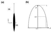
강도는 빔의 단면 중심에서 가장 높고 밖을 향해 감소한다. 이 경우에, 선형 빔 프로파일의 경우 강도의 구배는 제1 방향에서 가장 낮고, 제1 방향에 수직하게 연장하는 제2 방향에서 가장 높다. 선형 빔 프로파일의 강도 분포는 바람직하게는 대칭이어서, 초점에서의 단면 프로파일은 하나의 축이 최고 강도 구배에 평행하게 연장하고 나머지 다른 축이 최저 강도 구배에 평행하게 연장하는 2개의 상호 수직한 축에 의해 특징지워질 수 있다.The intensity is highest at the center of the cross section of the beam and decreases outward. In this case, for the linear beam profile, the gradient of intensity is the lowest in the first direction and the highest in the second direction extending perpendicular to the first direction. The intensity distribution of the linear beam profile is preferably symmetric such that the cross-sectional profile at the focal point is on two mutually perpendicular axes, one axis extending parallel to the highest intensity gradient and the other axis extending parallel to the lowest intensity gradient. Can be characterized.
단면 프로파일의 폭 - 또는 그 밖에 빔 폭 - 은 이하에서 강도가 중심에서의 값의 절반으로 떨어지는, 최저 강도 구배의 방향에서 단면 프로파일의 중심으로부터의 거리를 의미하는 것으로 이해된다.The width of the cross-sectional profile-or else the beam width-is understood below to mean the distance from the center of the cross-sectional profile in the direction of the lowest intensity gradient, in which the intensity drops to half of the value at the center.
또한, 단면 프로파일의 두께 - 또는 그 밖에 빔 두께 - 는 강도가 중심에서의 값의 절반으로 떨어지는, 최고 강도 구배의 방향에서 단면 프로파일의 중심으로부터의 거리를 의미하는 것으로 이해된다.Further, the thickness of the cross-sectional profile-or else the beam thickness-is understood to mean the distance from the center of the cross-sectional profile in the direction of the highest intensity gradient, in which the intensity drops to half of the value at the center.
빔 폭 및 빔 두께는 바람직하게는 반사 패턴이 검출되도록 의도되는 물체 내의 마이크로반사기의 크기 및 밀집도에 적합화된다. 이 경우에, 빔 두께는 바람직하게는 마이크로반사기의 평균 크기의 자릿수(order of magnitude)를 갖는다. 빔 폭은 바람직하게는 2개의 마이크로반사기 사이의 평균 거리의 자릿수를 갖는다.The beam width and beam thickness are preferably adapted to the size and density of the microreflector in the object for which the reflective pattern is intended to be detected. In this case, the beam thickness preferably has an order of magnitude of the microreflector. The beam width preferably has the number of digits of the average distance between the two microreflectors.
평균 크기는 산술 평균을 의미하는 것으로 이해된다. 자릿수는 두 크기가 10 미만 그리고 0.1 초과의 인자만큼 서로 차이가 나거나 동일함을 의미하는 것으로 이해된다.Mean size is understood to mean the arithmetic mean. The number of digits is understood to mean that the two sizes differ or are equal to each other by a factor of less than 10 and greater than 0.1.
본 발명에 따른 센서의 바람직한 일 실시양태에서, 빔 폭은 2.5 mm 내지 7 mm의 범위, 바람직하게는 3 mm 내지 6.5 mm의 범위, 특히 바람직하게는 4 mm 내지 6 mm의 범위, 아주 특히 바람직하게는 4.5 mm 내지 5.5 mm의 범위에 있다.In a preferred embodiment of the sensor according to the invention, the beam width is in the range of 2.5 mm to 7 mm, preferably in the range of 3 mm to 6.5 mm, particularly preferably in the range of 4 mm to 6 mm, very particularly preferably Is in the range of 4.5 mm to 5.5 mm.
빔 두께는 5 ㎛ 내지 1000 ㎛의 범위에 있다. 큰 신호-대-노이즈 비를 얻기 위해 그리고 정밀 구조물을 형성하기 위해, 5 ㎛ 내지 50 ㎛의 작은 빔 두께가 유익하다. 물체에 입사하는 단면 프로파일의 크기가 감소할수록, 강도가 더 작은 면적에 걸쳐 분포되기 때문에 신호-대-노이즈 비는 증가한다. 단면 프로파일의 크기가 감소함에 따라, 더욱 더 정밀한 구조물이 형성될 수 있다. 그러나 단면 프로파일의 크기가 감소함에 따라, 재생가능한 신호를 얻는 것이 점점 더 어려워진다는 것을 경험적으로 알았다. 이것은 명백히 마이크로반사기를 갖는 물체가 감소하는 단면 프로파일에 관해 더 이상 충분히 정밀하게 위치설정될 수 없다는 사실 때문이다. 재개된 반사 패턴의 검출시 영역을 충분히 정밀하게 맞히는 것이 명백히 점점 더 어려워진다. 물체 위에 포커싱된 빔의 경우에, 바람직한 빔 두께는 5 ㎛ 내지 50 ㎛의 범위, 바람직하게는 10 ㎛ 내지 40 ㎛의 범위, 특히 바람직하게는 20 ㎛ 내지 30 ㎛의 범위에 있다. 초점은 바람직하게는 센서로부터 0.5 mm 내지 10 mm의 거리에 위치한다.The beam thickness is in the range of 5 μm to 1000 μm. In order to obtain large signal-to-noise ratios and to form precision structures, small beam thicknesses of 5 μm to 50 μm are beneficial. As the size of the cross-sectional profile incident on the object decreases, the signal-to-noise ratio increases because the intensity is distributed over a smaller area. As the size of the cross-sectional profile is reduced, more precise structures can be formed. However, experience has shown that as the size of the cross-sectional profile decreases, it becomes increasingly difficult to obtain a reproducible signal. This is apparently due to the fact that objects with microreflectors can no longer be precisely positioned with respect to the decreasing cross-sectional profile. Obviously it becomes increasingly difficult to hit the area sufficiently precisely upon detection of the resumed reflection pattern. In the case of a beam focused on an object, the preferred beam thickness is in the range of 5 μm to 50 μm, preferably in the range of 10 μm to 40 μm, particularly preferably in the range of 20 μm to 30 μm. The focal point is preferably located at a distance of 0.5 mm to 10 mm from the sensor.
놀랍게도 빔 두께 및 빔 폭에 관한 전술된 범위가 한편으로는 재생 가능성을 위해 충분히 정밀한 위치설정을 얻기에, 다른 한편으로는 충분히 정밀한 인증을 위해 충분한 신호-대-노이즈 비를 얻기에 매우 적합하다는 것을 알았다.Surprisingly, the aforementioned ranges in terms of beam thickness and beam width are very well suited for obtaining enough precise positioning for reproducibility on the one hand and for sufficient signal-to-noise ratio for sufficiently precise authentication on the other hand. okay.
빔 폭 및 빔 두께의 선택에 영향을 미칠 수 있는 추가의 관점이 있다. 따라서, 본 발명에 따른 센서의 매우 컴팩트한 디자인이 렌즈에 의한 빔의 포커싱을 생략함으로써 실현될 수 있다. 대신에, 선형 빔 프로파일이 다이어프램에 의해 생성된다. 이 바람직한 실시양태가 도 5에 도시되어 있다. 여기서 빔 두께는 200 ㎛ 내지 1000 ㎛의 범위, 바람직하게는 200 ㎛ 내지 400 ㎛의 범위에 있으며, 빔 폭은 2 mm 내지 5 mm의 범위, 바람직하게는 2.5 mm 내지 3.5 mm의 범위에 있다.There is an additional aspect that can influence the choice of beam width and beam thickness. Thus, a very compact design of the sensor according to the invention can be realized by omitting the focusing of the beam by the lens. Instead, a linear beam profile is created by the diaphragm. This preferred embodiment is shown in FIG. 5. The beam thickness here is in the range of 200 μm to 1000 μm, preferably in the range of 200 μm to 400 μm and the beam width is in the range of 2 mm to 5 mm, preferably in the range of 2.5 mm to 3.5 mm.
본 발명에 따른 센서는 바람직하게는 복수의 센서를 결합하기 위한 또는 센서를 마운트(mount)에 결합하기 위한 수단을 갖는다.The sensor according to the invention preferably has means for joining a plurality of sensors or for coupling the sensors to a mount.
이 수단은 2개 이상의 센서가 사전결정된 방식으로 서로 결합되는 것을 가능하게 한다. 바람직하게는, 센서는 일측 상에 양의 결합 수단을 갖고 대향측 상에 음의 결합 수단을 가져, 센서는 규정된 방식으로 양측 상에서 각각의 추가 센서에 결합될 수 있으며, 여기서 추가 센서는 다음에는 아직 자유로운 측 상에서 추가 센서에도 또한 결합될 수 있다. 이 모듈 원리는 사전규정된 방식의 다수의 센서의 결합을 가능하게 한다. 고려되는 양의 결합 수단은, 예를 들어 음의 결합 수단으로서의 컷아웃(cutout)에 삽입될 수 있는 돌출부를 포함한다. 당해 분야의 숙련자에게 알려져 있는 추가의 결합 수단, 예를 들어 삽입 레일 등을 생각할 수 있다. 복수의 센서는 바람직하게는 센서들 모두의 빔 폭이 선을 따라 배열되는 방식으로 서로 결합된다.This means enables two or more sensors to be coupled to each other in a predetermined manner. Preferably, the sensor has positive coupling means on one side and negative coupling means on the opposite side such that the sensor can be coupled to each additional sensor on both sides in a defined manner, where the additional sensor is then It can also be coupled to additional sensors on the free side. This modular principle allows the combination of multiple sensors in a predefined manner. Positive engagement means contemplated include protrusions that can be inserted into a cutout, for example as negative coupling means. Additional coupling means known to those skilled in the art, for example insertion rails, can be envisioned. The plurality of sensors are preferably coupled to each other in such a way that the beam widths of all the sensors are arranged along a line.
2개 이상의 센서의 결합은 가역적인 방식으로 실행되며, 즉 결합은 분리가능하다. 결합 수단은 또한 본 발명에 따른 센서를 마운트에 설치하기 위해 사용될 수 있다.The joining of two or more sensors is performed in a reversible manner, ie the joining is detachable. Coupling means can also be used for mounting the sensor according to the invention to the mount.
다양한 센서의 결합이 다음이 이점을 제공한다.The combination of various sensors offers the following advantages:
■ 복수의 센서의 결합의 결과로서, 검출을 위한 지속 시간이 동일하게 남아 있는 상태에서, 더 많은 반사 데이터를 기록하고 따라서 식별 및/또는 인증 동안 보안을 증가시키는 것이 가능하다.As a result of the combination of multiple sensors, with the duration for detection remaining the same, it is possible to record more reflection data and thus increase security during identification and / or authentication.
소정 시간 간격으로 인증될 물체의 하나의 표면 영역 대신에, 결합된 센서들의 경우에 복수의 영역이 동일 시간 간격으로 조사되고 반사된 방사선이 검출된다. 따라서, 물체를 특징짓는 더 많은 양의 데이터가 기록된다. 이것은 다수의 유사한 물체들로부터 하나의 물체가 확실하게 식별 및 인증될 수 있는 정밀도를 증가시킨다.Instead of one surface area of the object to be authenticated at predetermined time intervals, in the case of combined sensors a plurality of areas are irradiated at the same time interval and the reflected radiation is detected. Thus, a larger amount of data characterizing the object is recorded. This increases the precision with which one object can be reliably identified and authenticated from multiple similar objects.
복수의 센서의 본 발명에 따른 분리가능한 결합은 사용자에게 각각의 응용에 대해 유연성 있게 반응할 수 있는 가능성을 제공한다. 식별 및/또는 인증 동안 더 높은 보안이 요구되는 경우, 2개 이상의 센서가 서로 결합될 수 있으며, 간단한 방식으로, 더 많은 양의 데이터가 동일하게 남아 있는 시간 간격에서 검출될 수 있다. 대조적으로, 예를 들어 간단한 인증의 점검만이 요구되는 경우, 개개의 센서가 사용될 수 있다.The separable combination according to the invention of a plurality of sensors gives the user the possibility to respond flexibly for each application. If higher security is required during identification and / or authentication, two or more sensors may be combined with each other and, in a simple manner, detected in a time interval in which a larger amount of data remains the same. In contrast, individual sensors can be used, for example, if only a simple check of authentication is required.
■ 복수의 센서의 결합의 결과로서, 복수의 물체를 동시에 검출하는 것이 가능하다. 예로서, 다수의 센서를 생산 설비에 설치하는 것이 가능하다. 제품은 예를 들어 컨베이어 벨트에 의해 고속으로 운반된다. 이 제품을 나중에 식별 및/또는 인증할 수 있기 위해, 특징적인 반사 패턴이 검출되고 예를 들어 데이터베이스에 저장되어야 한다. 이 목적을 위해, 검출 동안 처리량을 증가시키기 위해 복수의 센서를 결합하는 것이 유익하다. 제품들이 너무 멀리 떨어져 있어 서로 직접 결합된 센서들에 의해 더 이상 개별적으로 검출될 수 없는 경우 센서들을 스페이서에 의해 결합하는 것을 생각할 수 있다. 결합 수단은 센서들이 서로에 관해 규정된 위치를 취하는 방식으로 센서들을 서로 결합하는 것을 가능하게 한다. 결과로서, 데이터 획득 동안 재생 가능성이 증가되며 개별 제품들이 나중에 확실하게 식별 및/또는 인증될 수 있다.■ As a result of the combination of a plurality of sensors, it is possible to detect a plurality of objects at the same time. By way of example, it is possible to install multiple sensors in a production facility. The product is conveyed at high speed, for example by a conveyor belt. In order to be able to identify and / or authenticate this product later, characteristic reflection patterns must be detected and stored in a database, for example. For this purpose, it is beneficial to combine multiple sensors to increase throughput during detection. It is conceivable to combine the sensors by a spacer if the products are too far apart and can no longer be individually detected by the sensors directly coupled to each other. The coupling means make it possible to couple the sensors to each other in such a way that the sensors take a defined position with respect to each other. As a result, reproducibility is increased during data acquisition and individual products can be reliably identified and / or certified later.
본 발명은 마찬가지로 직접 또는 스페이서에 의해 가역적으로 서로 결합된 2개 이상의 센서를 포함하는 장치에 관한 것이다.The invention likewise relates to a device comprising two or more sensors directly or reversibly coupled to one another by a spacer.
본 발명에 따른 센서의 바람직한 일 실시양태에서, 센서는 광학 구성 요소가 그 안에 도입되는 하우징을 갖는다. 추가의 구성 요소, 예를 들어 레이저를 위한 제어 전자 기기, 신호 전처리 전자 기기, 완전 평가 전자 기기 등이 센서의 하우징 안에 도입될 수 있다. 하우징은 바람직하게는 또한 센서를 제어하기 위해 그리고/또는 특징적인 반사 패턴의 검출 및 추가 처리를 위해 본 발명에 따른 센서가 그것에 의해 연결될 수 있는 연결 케이블을 제어 유닛 및/또는 데이터 획득 유닛에 고정하는 역할을 한다.In one preferred embodiment of the sensor according to the invention, the sensor has a housing into which the optical component is introduced. Additional components, for example control electronics for the laser, signal preprocessing electronics, complete evaluation electronics and the like can be introduced into the housing of the sensor. The housing preferably also secures the connection cable to the control unit and / or the data acquisition unit, to which the sensor according to the invention can be connected, for controlling the sensor and / or for the detection and further processing of the characteristic reflection pattern. Play a role.
센서는 바람직하게는 또한, 하우징과 함께 손상 및 오염으로부터 광학 구성 요소를 보호하는 윈도우를 갖는다. 윈도우는 사용되는 방사원의 파장에 대해 적어도 부분적으로 투명하다.The sensor preferably also has a window with the housing that protects the optical component from damage and contamination. The window is at least partially transparent to the wavelength of the radiation source used.
본 발명에 따른 센서는 물체를 식별하고/거나 인증하기 위해 제어 및 데이터 획득 유닛과의 조합에 적합하다. 따라서, 본 발명은 또한 물체를 식별하고/거나 인증하기 위한 방법의 본 발명에 따른 센서의 용도에 관한 것이다.The sensor according to the invention is suitable for combination with a control and data acquisition unit for identifying and / or authenticating an object. The invention therefore also relates to the use of a sensor according to the invention of a method for identifying and / or authenticating an object.
식별은 사람 또는 물체를 명확하게 인지하는 역할을 하는 과정을 의미하는 것으로 이해된다. 인증은 주장된 동일성을 점검(검증)하는 과정을 의미하는 것으로 이해된다. 물체, 서류, 사람 또는 데이터를 인증하는 것은 이들이 진정한 것임을, 즉 이들이 변경되지 않았고, 복사되지 않았으며 그리고/또는 위조되지 않았음을 확인하는 것이다.Identification is understood to mean a process that serves to clearly recognize a person or object. Certification is understood to mean the process of checking (validating) claimed identity. Authenticating an object, document, person or data is to confirm that they are true, that is, they have not been altered, copied and / or forged.
식별 및/또는 인증되도록 의도되는 물체는, 물체에 설치되고/거나 물체 안에 도입되며 랜덤하게 분포 및/또는 배향되는 마이크로반사기를 포함한다. 이 경우에, 마이크로반사기 자체가 물체에 결합될 수 있다. 마이크로반사기를 바람직하게는 비가역적으로 물체에 결합된 보안 요소(예를 들어, 라벨) 안에 도입하는 것이 마찬가지로 가능하다. 그러한 보안 요소의 예가 독일 특허 DE102007044146A1호 또는 아직 공개되지 않은 국제 특허 출원 PCT/EP2009/000450호에 기술되어 있다.Objects intended to be identified and / or authenticated include microreflectors installed in and / or introduced into the object and randomly distributed and / or oriented. In this case, the micro reflector itself can be coupled to the object. It is likewise possible to introduce microreflectors into a security element (eg a label) which is preferably irreversibly coupled to the object. Examples of such security elements are described in German patent DE102007044146A1 or international patent application PCT / EP2009 / 000450, which is not yet published.
마이크로반사기는 방사된 전자기 방사선을 특징적인 방식으로 반사하는 적어도 하나의 표면을 포함하는 것을 특징으로 한다. 특징적인 반사는 적어도 하나의 파장을 갖는 전자기 방사선이 입사각에 의해 사전규정된 적어도 하나의 방향으로 반사되며, 여기서 적어도 하나의 파장을 갖는 반사된 방사선의 비율이 적어도 하나의 파장을 갖는 흡수 및 투과된 방사선의 비율의 합계보다 더 큰 것을 특징으로 한다. 따라서 적어도 하나의 표면의 반사율은 50%보다 크고, 여기서 반사율은 표면에 충돌하는 적어도 하나의 파장을 갖는 전자기 방사선의 강도에 대한, 표면으로부터 반사되는 적어도 하나의 파장을 갖는 전자기 방사선의 강도의 비를 의미하는 것으로 이해되어야 한다. 그러한 표면은 이하에서 반사 표면으로 지칭된다.The microreflector is characterized by including at least one surface that reflects the emitted electromagnetic radiation in a characteristic manner. Characteristic reflection is that electromagnetic radiation with at least one wavelength is reflected in at least one direction predefined by the angle of incidence, where the proportion of reflected radiation with at least one wavelength is absorbed and transmitted with at least one wavelength It is characterized in that it is larger than the sum of the ratios of the radiations. Thus the reflectance of at least one surface is greater than 50%, where the reflectance is the ratio of the intensity of the electromagnetic radiation with at least one wavelength reflected from the surface to the intensity of the electromagnetic radiation with at least one wavelength impinging on the surface. It should be understood as meaning. Such surfaces are referred to below as reflective surfaces.
마이크로반사기의 반사 표면은 크기가 1*10-14 m2 내지 1*10-5 m2이다. 바람직하게는, 반사 표면의 크기는 1*10-12 m2 내지 1*10-6 m2, 특히 바람직하게는 1*10-10 m2 내지 1*10-7 m2의 범위에 있다.The reflective surface of the microreflector has a size of 1 * 10 -14 m 2 to 1 * 10 -5 m 2 . Preferably, the size of the reflective surface is in the range of 1 * 10 −12 m 2 to 1 * 10 −6 m 2 , particularly preferably 1 * 10 −10 m 2 to 1 * 10 −7 m 2 .
바람직한 일 실시양태에서, 마이크로반사기는 최대 길이가 200 ㎛ 미만이고 두께가 2 내지 10 ㎛이며, 원형 형상, 타원형 형상 또는 n-각형 형상 - 여기서, n≥3 - 이다. 여기서 및 이하에서, 타원형은 엄격하게 수학적인 의미로 이해되어서는 안 된다. 직사각형 또는 평행사변형 또는 사다리꼴 또는 둥근 코너를 갖는 대체로 n-변 형태가 여기서 그리고 이하에서 마찬가지로 타원형으로 이해되어야 한다.In one preferred embodiment, the microreflector has a maximum length of less than 200 μm and a thickness of 2 to 10 μm and a circular shape, elliptical shape or n-square shape, where n ≧ 3. Here and below, ellipsoid should not be understood in a strictly mathematical sense. A generally n-sided shape with rectangular or parallelogram or trapezoidal or rounded corners should be understood as elliptical here and hereafter.
바람직한 일 실시양태에서, 마이크로반사기는 적어도 하나의 금속성 구성 요소를 포함한다. 시리즈 알루미늄, 구리, 니켈, 은, 금, 크롬, 아연, 주석 또는 이들 금속 중 적어도 2개로 구성된 합금으로부터의 금속이 바람직하게 포함된다. 마이크로반사기는 금속 또는 합금으로 코팅될 수 있거나 전적으로 금속/합금으로 구성될 수 있다.In one preferred embodiment, the microreflector comprises at least one metallic component. Metals from series aluminum, copper, nickel, silver, gold, chromium, zinc, tin or alloys composed of at least two of these metals are preferably included. Microreflectors may be coated with metals or alloys or may consist entirely of metals / alloys.
바람직한 일 실시양태에서, 예로서 국제 특허 공개 WO 2005/078530 A1호에 기술되어 있는 바와 같은 금속 식별 박판이 마이크로반사기로서 사용된다. 금속 식별 박판은 반사 표면을 갖는다. 다수의 그러한 금속 식별 박판이 투명 층에 랜덤하게 분포 및/또는 배향되는 경우, 투명 층의 조사시 특징적인 반사 패턴이 발생하며, 이 패턴은 식별 및 인증을 위해 사용될 수 있다.In one preferred embodiment, a metal identification sheet as described by way of example in WO 2005/078530 A1 is used as the microreflector. The metal identification sheet has a reflective surface. When a large number of such metal identification thin plates are randomly distributed and / or oriented in the transparent layer, a characteristic reflection pattern occurs upon irradiation of the transparent layer, which can be used for identification and authentication.
랜덤한 분포 및/또는 배향은 투명 층 내에서의 개별 마이크로반사기의 위치 및/또는 개별 마이크로반사기의 배향이 생산 공정에 의해 예견할 수 있는 방식으로 설정될 수 없음을 의미하는 것으로 이해된다. 독일 특허 DE102007044146A1호에 기술되어 있는 바와 같은 마이크로반사기를 포함하는 열가소성 물질을 제조하기 위한 방법이, 투명 층 안에 마이크로반사기의 랜덤한 분포 및/또는 배향을 형성하기에 적합하다. 개별 마이크로반사기의 위치 및/또는 배향은 생산 공정 동안 랜덤하게 변동된다. 따라서 개별 마이크로반사기의 위치 및/또는 배향은 간단한 방식으로 복제될 수 없다.Random distribution and / or orientation is understood to mean that the position of the individual microreflectors and / or the orientation of the individual microreflectors in the transparent layer cannot be set in a predictable manner by the production process. The method for producing a thermoplastic comprising a microreflector as described in German patent DE102007044146A1 is suitable for forming a random distribution and / or orientation of the microreflector in the transparent layer. The position and / or orientation of the individual microreflectors varies randomly during the production process. Thus the position and / or orientation of the individual microreflectors cannot be duplicated in a simple manner.
그러한 보안 요소에 의해 제공되는 높은 보호는, 그러한 보안 요소가 지극히 고도의 노력에 의해서만 복제될 수 있다는 사실에 기초하고 있다.The high protection provided by such security elements is based on the fact that such security elements can only be replicated by extremely high efforts.
이 경우에, 랜덤은 엄격하게 수학적인 의미로 이해되어서는 안 된다. 랜덤은 개별 마이크로반사기의 위치 및 배향의 정확한 예측 가능성을 불가능하게 만드는 랜덤한 요소가 있음을 의미한다. 그러나, 마이크로반사기가 바람직한 위치 및/또는 배향을 갖는 것을 생각할 수 있다. 생산 공정에 의해 결정될 수 있는 분포가 이 바람직한 위치 및/또는 바람직한 배향의 주위에 형성된다. 그러나, 개별 마이크로반사기의 위치 및/또는 배향은 확실히 알 수 없는 상태로 유지된다.In this case, random should not be understood in a strictly mathematical sense. Random means that there is a random element that makes it impossible to accurately predict the position and orientation of individual microreflectors. However, it is conceivable that the micro reflector has the desired position and / or orientation. A distribution that can be determined by the production process is formed around this preferred location and / or preferred orientation. However, the position and / or orientation of the individual microreflectors remains reliably unknown.
마이크로반사기는, 전자기 방사를 위한 방사원, 적어도 하나의 반사기의 적어도 하나의 반사 표면, 및 반사되는 전자기 방사선을 위한 검출기를 포함하는 장치가 반사 법칙을 따르는 경우, 적어도 하나의 파장을 갖는 전자기 방사선을 반사하는 특성을 갖는다.The microreflector reflects electromagnetic radiation having at least one wavelength when a device comprising a radiation source for electromagnetic radiation, at least one reflective surface of the at least one reflector, and a detector for reflected electromagnetic radiation conforms to the law of reflection It has the characteristic to
물체를 인증하기 위한 방법은 적어도 다음의 단계를 포함한다.The method for authenticating an object includes at least the following steps.
(A) 센서에 관해 물체를 배향하는 단계, (A) orienting the object relative to the sensor,
(B) 전자기 방사선으로 물체의 적어도 일부분을 조사하는 단계,(B) irradiating at least a portion of the object with electromagnetic radiation,
(C) 마이크로반사기에서 반사되는 방사선을 검출하는 단계,(C) detecting the radiation reflected from the microreflector,
(D) 센서에 관한 물체의 상대 위치를 변경하는 단계,(D) changing the relative position of the object with respect to the sensor,
(E) 적절한 경우 단계 (B), (C) 및 (D)를 다수회 반복하는 단계,(E) repeating steps (B), (C) and (D) as many times as appropriate,
(F) 상대 위치에 따라 검출된 반사 패턴과 적어도 하나의 원하는 패턴을 비교하는 단계,(F) comparing the detected reflection pattern with the at least one desired pattern according to the relative position,
(G) 단계 (F)에서의 비교 결과에 따라 물체의 진위에 관한 통지를 출력하는 단계.(G) outputting a notification regarding the authenticity of the object according to the comparison result in step (F).
바람직하게는, 상이한 위치에서 및/또는 상이한 배향 각도로 번쩍이는 마이크로반사기가 방사원(레이저) 및 광검출기에 관한 물체의 상대 위치의 함수로서 기록되도록, 인증될 물체 및/또는 센서는 서로에 관해 이동된다.Preferably, the objects and / or sensors to be authenticated with respect to each other are such that the microreflectors flashing at different positions and / or at different orientation angles are recorded as a function of the relative positions of the objects with respect to the radiation source (laser) and the photodetector. Is moved.
위치의 변화는 가속 방식 또는 감속 방식으로 일정 속도에서 연속적으로, 또는 불연속적으로, 즉 예를 들어 계단 방식으로 실행될 수 있다.The change of position can be carried out continuously or discontinuously at a constant speed, i. E. In a stepwise manner, in an acceleration or deceleration manner.
단계 (E)에서의 단계 (B), (C) 및 (D)의 반복은 충분한 개수의 마이크로반사기가 검출될 때까지 수행된다. 이 충분한 개수는 각각의 응용에 의해 사전규정된다. 다수의 상이한 물체들이 있고, 그 각각의 개별 물체가 확실하게, 즉 예를 들어 99% 초과의 가능성으로 인증되는 것이 의도되는 경우, 개별 물체의 반사 패턴은 충분히 차별화되어야 한다. 2개의 상이한 물체로부터의 반사 패턴이 동일할 가능성은 반사 패턴을 기록하기 위해 검출되는 마이크로반사기의 개수에 따라 감소한다. 이 점에서, 차별화될 물체의 개수 및 물체가 그 정도로 인증되도록 의도되는 확실성이 검출될 마이크로반사기의 개수를 결정한다.The repetition of steps (B), (C) and (D) in step (E) is performed until a sufficient number of microreflectors are detected. This sufficient number is predefined by each application. If there are a large number of different objects and each individual object is intended to be reliably authenticated, ie with a probability of greater than 99%, for example, the reflection pattern of the individual objects must be sufficiently differentiated. The likelihood of reflection patterns from two different objects being the same decreases with the number of microreflectors detected to record the reflection pattern. In this regard, the number of objects to be differentiated and the certainty that the objects are intended to be authenticated to that extent determine the number of microreflectors to be detected.
인증 동안, 현재 검출된 반사 패턴과 생각하고 있는 물체의 반사 패턴(원하는 패턴) 사이의 이른바 1:1 매칭(matching)은 단계 (F)에서 일어난다. 반사 패턴은 센서에 관한 물체의 위치에 의존하는 방식으로 검출되는 마이크로반사기로부터의 반사물을 의미한다. 따라서 반사 패턴은 예를 들어 마이크로반사기로부터 반사되는 방사선의 강도 - 상기 강도는 상이한 위치에서, 상이한 각도에서 측정됨 - 가 기록되어 있는 수치표(numerical table)의 형태로 존재한다. 그러한 수치표는 원하는 수치표와 직접 비교될 수 있다. 원하는 패턴과의 비교가 수행되기 전에 수학적인 조작에 의해 측정된 강도 분포로부터 반사 패턴의 상이한 표현을 생성하는 것이 마찬가지로 가능하다.During authentication, a so-called 1: 1 matching between the currently detected reflection pattern and the reflection pattern (desired pattern) of the object under consideration takes place in step (F). By reflection pattern is meant a reflection from a micro reflector that is detected in a manner that depends on the position of the object with respect to the sensor. The reflection pattern thus exists in the form of a numerical table in which the intensity of the radiation reflected from the microreflector, for example, is measured at different angles at different locations. Such numerical tables can be compared directly with the desired numerical tables. It is likewise possible to produce different representations of the reflection pattern from the intensity distribution measured by mathematical manipulations before the comparison with the desired pattern is performed.
인증 동안, 먼저 예를 들어 물체에 결합된 바코드에 기초하여 물체의 동일성을 결정하고, 그 다음에 현재 측정된 반사 패턴과 식별된 물체에 할당된 반사 패턴 사이의 비교에 의해 할당의 정확성을 확인하는 것을 생각할 수 있다.During authentication, first of all, the identity of the object is determined based on, for example, a bar code bound to the object, and then the accuracy of the assignment is checked by comparison between the currently measured reflection pattern and the reflection pattern assigned to the identified object. You can think of it.
센서는 마찬가지로 특징적인 반사 패턴에 기초하여 물체를 직접 식별하기 위해 사용될 수 있다. 본 발명에 따른 센서의 도움으로 물체를 식별하는 방법은 적어도 앞서 논의된 실시양태에서 인증 방법을 위해 이미 논의된 단계 (A) 내지 (G)를 포함하며, 단계 (G)에서 진위에 관한 통지 대신에 물체의 동일성에 관한 통지가 실행된다:The sensor can likewise be used to directly identify an object based on the characteristic reflection pattern. The method of identifying an object with the aid of a sensor according to the invention comprises steps (A) to (G) already discussed for the authentication method in at least the embodiments discussed above, in place of notification of authenticity in step (G). The notification about the identity of the object is executed at:
(G) 단계 (F)에서의 비교 결과에 따라 물체의 동일성에 관한 통지를 출력하는 단계.(G) outputting a notification regarding the identity of the object according to the comparison result in step (F).
본 발명에 따른 방법의 단계 (F)에서, 고려중인 물체의 반사 패턴은 먼저 이미 결정된 반사 패턴과 비교된다. 이 점에서, 물체의 동일성이 반사 패턴에 의해 결정되고, 고려중인 반사 패턴과 이미 검출된 물체의 반사 패턴 - 데이터베이스에 저장되어 있음 - 전부의 매칭이 실행된다(1:n 매칭).In step (F) of the method according to the invention, the reflection pattern of the object under consideration is first compared with the already determined reflection pattern. At this point, the identity of the object is determined by the reflection pattern, and matching of the reflection pattern under consideration and the reflection pattern of the already detected object-stored in the database-is performed (1: n matching).
본 발명에 따른 센서의 사용은 물체의 식별 및/또는 인증이 기계에 의해 수행되거나 기계에 의해 지지될 수 있는 이점을 제공하며, 물체가 주장된 물체에 대응하는 가능성의 양적 평가를 가능하게 한다. 기계 수행 및 지지는 물체의 특징적인 반사 패턴에 기초하여 더 짧은 시간 안에 그리고 예를 들어 독일 특허 DE102007044146A1호에 기술되어 있는 바와 같이 현미경의 도움을 받는 (전적으로) 사람-기반의 수행보다 더 낮은 비용으로 다수의 물체의 점검을 가능하게 한다. 또한, 기계 수행 또는 기계 지지는 상이한 시간에 인증된 반사 패턴들의 비교를 가능하게 한다. 그것에 의해 물체의 추적이 가능하게 된다(트랙 앤드 트레이스).The use of the sensor according to the invention provides the advantage that the identification and / or authentication of the object can be carried out or supported by the machine, and enables the quantitative assessment of the likelihood that the object corresponds to the claimed object. Mechanical performance and support is based on the characteristic reflection pattern of the object in less time and at lower cost than (all) human-based performance with the aid of a microscope as described, for example, in German patent DE102007044146A1. Allows inspection of multiple objects. In addition, machine performance or machine support enables comparison of authorized reflection patterns at different times. This allows tracking of the object ( track and trace ).
본 발명을 제한하지 않고서 구체적이고 예시적인 실시양태에 기초하여 본 발명이 아래에서 더 상세하게 설명된다.The present invention is described in more detail below on the basis of specific and exemplary embodiments without limiting the invention.
도 1a 및 도 1b는 광학 구성 요소를 갖고 있지 않는 본 발명에 따른 센서의 바람직한 실시양태를 사시도로 보여주는 도면이다.
도 2는 본 발명에 따른 센서의 블록을 단면도로 보여주는 도면이다.
도 3은 커버를 갖고 있는 하우징을 보여주는 도면이다.
도 4는 선형 빔 프로파일의 개략도이다.
도 5는 본 발명에 따른 센서의 바람직한 실시양태의 개략도이다.
도 6은 선형 빔 프로파일을 생성하기 위한 평철(planoconvex) 원통형 렌즈를 보여주는 도면이다.
[부호의 설명]
1 센서
10 블록
11 부싱
12 부싱
13 부싱
14 외측 표면에 대한 법선
15 반사각
18 외측 표면
20 초점
30 유지 요소
50 하우징
51 부싱, 결합 수단
52 부싱, 결합 수단
55 케이블 부싱
60 커버
62 컷아웃
70 방사원
80 광검출기
90 다이어프램
100 입사 빔
110 반사 빔
200 표면
300 평철 원통형 렌즈
α 입사각
β 반사각1a and 1b show in perspective view a preferred embodiment of a sensor according to the invention without an optical component.
2 is a cross-sectional view of a block of a sensor according to the present invention.
3 shows a housing with a cover.
4 is a schematic diagram of a linear beam profile.
5 is a schematic diagram of a preferred embodiment of a sensor according to the invention.
6 shows a planoconvex cylindrical lens for producing a linear beam profile.
[Description of the code]
1 sensor
10 blocks
11 bushing
12 bushing
13 bushing
14 Normal to outer surface
15 reflection angles
18 outer surface
20 focus
30 retaining elements
50 housing
51 bushing, coupling means
52 bushings, coupling means
55 cable bushing
60 covers
62 cutouts
70 radiation sources
80 photodetector
90 diaphragm
100 incident beam
110 reflective beam
200 surfaces
300 flat iron cylindrical lens
α incident angle
β reflection angle
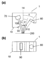
도 1a 및 도 1b는 광학 구성 요소를 갖고 있지 않는 본 발명에 따른 센서(1)를 사시도로 보여준다. 도 2는 도 1a 및 도 1b로부터의 센서(1)를 단면도로 보여준다.1a and 1b show in perspective view a
센서(1)의 주요 요소는 블록(10)에 의해 형성되며, 블록은 바람직하게는 1개 또는 2개의 단편으로 구현되고 본 발명에 따른 센서의 광학 구성 요소 전부를 수용하는 역할을 한다.The main element of the
광학 구성 요소는 레이저 및 포토다이오드 자체를 비롯하여 방사원과 광검출기 사이의 빔 경로에 배열되는 센서의 모든 구성 요소를 의미하는 것으로 이해된다. 광학 요소는 빔 성형 및 포커싱의 역할을 하는 각종 광학 구성 요소를 이룬다. 특히, 렌즈, 다이어프램, 회절 광학 요소 등이 광학 요소로 지칭된다.Optical components are understood to mean all components of the sensor arranged in the beam path between the radiation source and the photodetector, including the laser and photodiode itself. Optical elements form various optical components that serve as beam shaping and focusing. In particular, lenses, diaphragms, diffractive optical elements and the like are referred to as optical elements.
광학 블록(10)은 특정 외측 표면(18)을 포함하며, 특정 외측 표면은 물체의 특징적인 반사 패턴의 검출 동안 상기 물체로 지향된다. 블록(1)은 특정 외측 표면(18) - 이하, 간단하게 외측 표면으로 지칭됨 - 의 방향으로 서로를 향해 연장하는 부싱(bushing)(11, 12, 13)을 포함한다. 제1 부싱(11)은 방사원을 수용하는 역할을 한다. 이 부싱(11)은 외측 표면에 대한 법선에 대해 각도 αA로 연장한다. 외측 표면에 대한 법선 또는 생략하여 외측 표면 법선은, 외측 표면에 수직하며 부싱의 방향으로 지향되는 직선이다.
각도 αA는 0°내지 60°의 범위, 바람직하게는 15° 내지 40°의 범위, 특히 바람직하게는 20° 내지 35°의 범위, 아주 특히 바람직하게는 25° 내지 30°의 범위이다. 본 예에서는 각도 αA = 27°이다.The angle α A is in the range from 0 ° to 60 °, preferably in the range from 15 ° to 40 °, particularly preferably in the range from 20 ° to 35 °, very particularly preferably in the range from 25 ° to 30 °. In this example, the angle α A = 27 °.
물체를 식별하고/거나 인증하기 위해 본 발명에 따른 센서를 사용할 때, 센서는 바람직하게는 물체의 표면과 외측 표면이 서로 평행하게 연장하는 방식으로 물체의 표면에 관해 배향된다. 이 경우에, 전자기 방사선이 표면 법선에 대해 각도 α로 물체의 표면에 입사한다. 이 경우에, 각도 αA는 입사 방사선의 입사각 α에 대응한다.When using the sensor according to the invention for identifying and / or authenticating an object, the sensor is preferably oriented with respect to the surface of the object in such a way that the surface of the object and the outer surface extend parallel to each other. In this case, electromagnetic radiation is incident on the surface of the object at an angle α with respect to the surface normal. In this case, the angle α A corresponds to the incident angle α of the incident radiation.
입사 방사선의 일부가 표면 법선에 대해 반사각 β로 표면에서 다시 직접 분산된다. 반사 법칙에 따라, α=-β가 유효하다.A portion of the incident radiation is dispersed directly back at the surface at a reflection angle β with respect to the surface normal. According to the law of reflection, α = -β is valid.
본 발명에 따르면, 적어도 하나의 광검출기가 반사각 β에 대해 각도 γ로 배열된다. 이 목적을 위해, 본 발명에 따른 센서의 블록은 광검출기를 수용하기 위한 적어도 하나의 추가 대응 부싱(12, 13)을 포함한다.According to the invention, at least one photodetector is arranged at an angle γ with respect to the reflection angle β. For this purpose, the block of the sensor according to the invention comprises at least one further corresponding
본 발명에 따른 센서의 블록은 광검출기를 수용하기 위한 추가 부싱을 포함할 수 있다. 도시된 특히 바람직한 실시양태에서, 블록은 엄밀하게 광검출기를 수용하기 위한 2개의 부싱(12, 13)을 포함한다. 이 부싱들은 방사원을 위한 부싱(11)과 함께 한 평면에 위치한다. 그것들은 바람직하게는 외측 표면 법선에 대해 각도 γ1 및 γ2로 연장한다. 광검출기는 외측 표면을 향해 지향되는 방식으로 부싱 안에 배열된다. 각도 γ1 및 γ2는 5°내지 60°의 범위, 바람직하게는 5°내지 30°의 범위, 특히 바람직하게는 10°내지 20°의 범위에 있으며, 이하의 기술은 항상 i=1 및 i=2에 대해 α-γi≥0, α+γi≤90°이 유효하도록 의도된다. 본 예에서, 각도는 γ1=-13.5°이고 γ2=13.5°이다.The block of sensors according to the invention may comprise an additional bushing for receiving the photodetector. In the particularly preferred embodiment shown, the block strictly includes two
부싱(11, 12, 13) 모두가 바람직하게는 한 평면에 위치한다.Both
방사원 및 2개의 광검출기를 수용하기 위한 부싱을 갖는 블록을 포함하는, 도 1a, 도 1b 및 도 2에 도시된 본 발명에 따른 센서의 실시양태는, 광학 구성 요소가 간단한 방식이지만 그럼에도 불구하고 서로에 관해 규정된 방식으로 배열될 수 있는 이점을 제공한다. 바람직하게는, 방사원을 위한 부싱 안에 스톱(stop)이 위치된다. 방사원은 상기 스톱에 대항하여 부싱 안에 밀어 넣어져, 방사원은 블록 및 2개의 추가 부싱에 관해 사전규정된 고정 위치를 취한다. 방사원이 그것에 이미 접속되어 있는 빔 성형 및 포커싱을 위한 광학 요소를 갖는 경우 - 이것은 예를 들어 현재 구매가능한 레이저 방사원의 경우에 대체로 통상적임 - 방사원의 고정의 결과로서, 동시에 방사원의 초점이 확실하게 고정된다. 광검출기를 수용하기 위한 추가 부싱에 마찬가지로 스톱이 제공될 수 있으며, 여기서 광검출기의 위치는 방사원의 위치보다 덜 정밀해야 한다.Embodiments of the sensor according to the invention shown in FIGS. 1A, 1B and 2, which include a block having a radiation source and a bushing for receiving two photodetectors, each of which has an optical component in a simple manner but nevertheless It provides an advantage that can be arranged in a prescribed manner with respect to. Preferably, a stop is located in the bushing for the radiation source. The radiation source is pushed into the bushing against the stop so that the radiation source takes a predefined fixed position with respect to the block and two further bushings. If the radiation source has optical elements for beam shaping and focusing already connected to it-this is usually common, for example in the case of laser radiation sources currently available-as a result of the fixation of the radiation source, at the same time the focus of the radiation source is reliably fixed do. An additional bushing for receiving the photodetector may likewise be provided with a stop, where the position of the photodetector should be less precise than the position of the radiation source.
블록(10)은 예를 들어 사출 성형 방법에 의해 간단한 방법으로 플라스틱으로부터 1개 또는 2개의 단편으로 제조될 수 있다. 구성 요소는 사출 성형 방법에 의해 단시간에 대량으로 고정밀도로 제조될 수 있다. 이것은 충분히 정밀한 구성 요소의 비용 효율적인 연속 생산을 가능하게 한다. 부싱은 이미 사출 주형(mould) 안에 제공되어 있거나, 나중에 예를 들어 드릴 구멍(drilled hole)에 의해 블록 안으로 도입될 수 있다. 바람직하게는, 블록의 구성 부품 모두가 사출 성형 방법의 일 단계에서 이미 제조된다. 예를 들어 알루미늄 또는 플라스틱으로부터의 블록을 밀링하고 드릴 구멍에 의해 부싱을 실현하는 것을 마찬가지로 생각할 수 있다. 당업계의 숙련자에게 알려져 있는 규정된 부싱을 갖는 블록을 제조하기 위한 추가 방법을 생각할 수 있다.The
본 발명에 따른 센서(1)는 또한 부싱(11, 12, 13)의 중심 축들이 블록(10)의 외측에 위치한 지점(20)에서 교차한다는 점에서 특징이 있다(도 2 참조). 놀랍게도 중심 축들의 교차 지점(20)이 외측 표면으로부터 0.5 내지 10 mm의 거리에 위치하는 경우 반사 패턴의 검출에 유익하다는 것을 알았다. 바람직한 일 실시양태에서, 교차 지점(20)은 동시에 초점이다.The
마이크로반사기에 의해 물체의 표면에 생성된 반사 패턴을 검출하기 위해, 본 발명에 따른 센서는 상응하여 상기 물체 위의 소정 거리에 안내되어, 중심 축들의 교차 지점이 물체의 표면 상에 위치한다.In order to detect the reflection pattern generated on the surface of the object by the microreflector, the sensor according to the invention is correspondingly guided a certain distance above the object such that the intersection of the central axes is located on the surface of the object.
전술된 0.5 내지 10 mm의 거리 범위의 경우에, 방사원 및 광검출기에 관해 검출될 물체의 그 표면의 위치설정이 간단하고 충분히 정밀한 방법으로 가능하다. 센서와 물체 사이의 거리가 증가하면, 표면의 사전규정된 영역을 검출할 수 있기 위해 물체의 표면에 관한 센서의 각도가 점점 더 정확히 준수되어야 하며, 그 결과 위치설정을 수행하기 위한 요건이 증가한다.In the case of the distance range of 0.5 to 10 mm described above, the positioning of that surface of the object to be detected with respect to the radiation source and the photodetector is possible in a simple and sufficiently precise manner. As the distance between the sensor and the object increases, the angle of the sensor with respect to the surface of the object must be observed more and more accurately in order to be able to detect a predefined area of the surface, which in turn increases the requirements for performing positioning. .
또한, 방사 강도는 방사원으로부터의 거리가 증가함에 따라 감소하여, 센서와 물체 사이의 증가하는 거리 때문에, 물체에 도달하는 상응하여 감소된 방사 강도는 방사원의 더 높은 출력에 의해 보충되어야 할 것이다. 그러나, 본 발명에 따른 센서는 바람직하게는 광범위한 보호 조치 없이 센서를 작동시킬 수 있도록 하기 위해 1등급 또는 2등급 레이저를 갖추고 있다. 이것은 센서가 "개방"형이기 때문에(즉, 레이저 빔은 센서로부터 방해받지 않고 방출됨) 특히 유효하다. 이것은 방사원의 출력이 임의로 증가될 수 없음을 의미한다. 이 점에서, 0.5 내지 10 mm의 본 발명에 따른 짧은 거리가 유익하다.In addition, the radiation intensity decreases as the distance from the radiation source increases, and because of the increasing distance between the sensor and the object, the correspondingly reduced radiation intensity reaching the object will have to be compensated for by the higher output of the radiation source. However, the sensor according to the invention is preferably equipped with a
도 1a, 도 1b 및 도 2의 블록(10)은 또한 윈도우를 수용 및 고정하기 위한 유지 수단(30)을 포함한다. 윈도우(도면에 도시되지 않음)는 사용되는 방사원의 파장에 대해 적어도 부분 투과성이다. 부분 투과성은 적어도 50%의 투과율, 즉 방사된 방사 강도의 50%가 윈도우를 통과함을 의미하는 것으로 이해된다.
도 3의 (a) 및 도 3의 (b)는 도 1a, 도 1b 및 도 2로부터의 센서가 그 안으로 도입될 수 있는 하우징(50)을 사시도로 보여준다. 도 3의 (c)는 하우징과 관련된 커버(60)를 보여준다. 하우징은 부싱(51, 52)을 갖는다. 부싱은 복수의 센서를 분리가능하게 서로 결합하기 위해 또는 센서를 마운트에 고정하기 위해 결합 수단으로서 사용될 수 있다. 커버(60)는 대응 컷아웃(cutout)(62)을 갖는다. 케이블 부싱(55)을 통해, 센서가 반사 데이터를 기록하기 위해 제어 전자기기 및/또는 컴퓨터 유닛에 연결된다.3 (a) and 3 (b) show in perspective view a
도 5는 본 발명에 따른 센서(1)의 추가의 바람직한 실시양태를 개략도로 보여준다. 도 5의 (a)는 센서를 측면으로부터 단면도로 보여주며, 도 5의 (b)는 표면(200)에 면하는 밑면으로부터 센서를 보여준다.5 shows a schematic view of a further preferred embodiment of the
센서(1)는 방사원(70) 및 광검출기(80)를 포함한다. 센서(1)의 외측 표면(18)이 물체의 표면(200) 위에 평행하게 안내되는 경우, 방사선(100)은 법선(14)에 대해 각도 α로 표면(200)에 입사한다. 표면(200)에서 반사되는 방사선(110)은 법선(14)에 대해 각도 β로 복귀된다. 반사 법칙에 따라, |α|=|β|가 유효하다. 광검출기는 각도 α 및 δ의 크기가 상이한 방식으로(|α|≠|δ|) 본 발명에 따라 배열되기 때문에, 반사된 방사선(110)은 광검출기(80)에 충돌하지 않는다.The
본 예에서, 선형 빔 프로파일은 다이어프램(90)에 의해 생성된다. 센서(외측 표면(18))와 물체(표면(200)) 사이의 거리는 바람직하게는 0.2 내지 10 mm이다.In this example, the linear beam profile is generated by the
도 4의 (a) 및 도 4의 (b)는 빔폭 SB 및 빔 두께 SD를 갖는 선형 빔 프로파일을 예시한다. 도 4의 (a)는 초점에서의 빔의 2차원 단면 프로파일을 예시한다. 최고 강도는 단면 프로파일의 중심에 존재한다. 강도 Ⅰ는 밖을 향해 감소하며, 여기서 중심으로부터의 거리 A가 증가함에 따라 강도 Ⅰ가 최대 정도까지 감소하는 제1 방향(x)과, 제1 방향(x)에 수직하며 중심으로부터의 거리 A가 증가함에 따라 강도 Ⅰ가 최소 정도까지 감소하는 추가의 방향(y)이 있다. 도 4의 (b)는 중심으로부터의 거리 A의 함수로서 강도 프로파일 Ⅰ을 보여준다. 빔 폭 및 빔 두께는 강도 Ⅰ가 중심에서의 최대값의 50%로 떨어지는 중심으로부터의 거리로서 규정되며, 여기서 빔 폭은 y-방향으로 놓여 있고 빔 두께는 x-방향으로 놓여 있다.4 (a) and 4 (b) illustrate a linear beam profile with beamwidth SB and beam thickness SD. 4A illustrates a two-dimensional cross-sectional profile of the beam at the focal point. The highest strength is at the center of the cross-sectional profile. The intensity I decreases outwards, where the first direction x in which the intensity I decreases to a maximum degree as the distance A from the center increases, and the distance A from the center perpendicular to the first direction x is There is an additional direction y with increasing intensity I to a minimum. 4 (b) shows the intensity profile I as a function of the distance A from the center. The beam width and beam thickness are defined as the distance from the center where the intensity I drops to 50% of the maximum at the center, where the beam width lies in the y-direction and the beam thickness lies in the x-direction.
도 6은 어떻게 선형 빔 프로파일이 평철 원통형 렌즈(300)의 도움으로 생성될 수 있는지를 예로서 보여준다. 원통형 렌즈(300)는 한 평면에서 수렴 렌즈로서 작용한다(도 6의 (b)). 한 평면에 수직한 평면에서, 상기 렌즈는 굴절 효과를 갖지 않는다. 동축 근사에서, 다음의 공식이 그러한 렌즈의 초점 길이 f에 관해 유효하다. 6 shows by way of example how a linear beam profile can be generated with the aid of the flat iron

여기서, R은 원통 반경이고 n은 물질의 굴절률이다.Where R is the cylinder radius and n is the refractive index of the material.
Claims (15)
- 전자기 방사선이 각도 α로 물체 위로 투과될 수 있는 방식으로 배열되는, 전자기 방사를 위한 방사원, 및
- 각도 δ로 물체로부터 반사되는 방사선이 검출되는 방식으로 배열되는, 반사되는 방사선을 픽업(pick up)하기 위한 광검출기
를 포함하며, 각도 α및 δ의 크기가 상이한(|α|≠| δ|) 것을 특징으로 하는, 조사(irradiation)시 랜덤하게 분포 및/또는 배향된 마이크로반사기(microreflector)에 의해 물체 안에 또는 물체 상에 생성되는 반사 패턴을 검출하기 위한 센서.At least
A radiation source for electromagnetic radiation, arranged in such a way that electromagnetic radiation can be transmitted over the object at an angle α, and
A photodetector for picking up the reflected radiation, arranged in such a way that the radiation reflected from the object at an angle δ is detected
An object within or by an object with a randomly distributed and / or oriented microreflector upon irradiation, characterized in that the magnitudes of the angles α and δ are different (| α | ≠ | δ |). Sensor for detecting a reflection pattern generated on the image.
(A) 센서 또는 장치에 대해 물체를 배향하는 단계,
(B) 전자기 방사선으로 물체의 적어도 일부분을 조사하는 단계,
(C) 마이크로반사기에서 반사되는 방사선을 검출하는 단계,
(D) 센서 또는 장치에 대한 물체의 상대 위치를 변경하는 단계,
(E) 적절한 경우 단계 (B), (C) 및 (D)를 다수회 반복하는 단계,
(F) 상대 위치에 따라 검출된 반사 패턴과 적어도 하나의 원하는 패턴을 비교하는 단계, 및
(G) 단계 (F)에서의 비교 결과에 따라 물체의 동일성 및/또는 진위에 관한 통지를 출력하는 단계
를 포함하는 용도.The method according to any one of claims 12 to 14,
(A) orienting an object relative to the sensor or device,
(B) irradiating at least a portion of the object with electromagnetic radiation,
(C) detecting the radiation reflected from the microreflector,
(D) changing the relative position of the object relative to the sensor or device,
(E) repeating steps (B), (C) and (D) as many times as appropriate,
(F) comparing the detected reflection pattern with at least one desired pattern according to the relative position, and
(G) outputting a notification regarding the identity and / or authenticity of the object according to the comparison result in step (F)
Use comprising a.
Applications Claiming Priority (2)
| Application Number | Priority Date | Filing Date | Title |
|---|---|---|---|
| DE102008051409.8 | 2008-10-11 | ||
| DE102008051409A DE102008051409A1 (en) | 2008-10-11 | 2008-10-11 | security element |
Publications (1)
| Publication Number | Publication Date |
|---|---|
| KR20110081973A true KR20110081973A (en) | 2011-07-15 |
Family
ID=41211857
Family Applications (1)
| Application Number | Title | Priority Date | Filing Date |
|---|---|---|---|
| KR1020117008108A KR20110081973A (en) | 2008-10-11 | 2009-04-17 | Optical sensor |
Country Status (8)
| Country | Link |
|---|---|
| US (1) | US20110176137A1 (en) |
| EP (1) | EP2338148A1 (en) |
| JP (1) | JP2012505532A (en) |
| KR (1) | KR20110081973A (en) |
| CN (1) | CN102171730A (en) |
| DE (1) | DE102008051409A1 (en) |
| TW (1) | TW201029860A (en) |
| WO (1) | WO2010040422A1 (en) |
Families Citing this family (16)
| Publication number | Priority date | Publication date | Assignee | Title |
|---|---|---|---|---|
| DE102009017668A1 (en) * | 2009-04-16 | 2010-10-21 | Bayer Technology Services Gmbh | Optical sensor for identifying and / or authenticating objects |
| DE102009025061A1 (en) | 2009-06-10 | 2010-12-16 | Bayer Technology Services Gmbh | Method for generating e.g. barcode of paper to identify object, involves combining signatures with object, storing signatures in specific form in radio-frequency identification-chip and comparing signatures with reference signatures |
| DE102009059054A1 (en) | 2009-12-18 | 2011-06-22 | Bayer Technology Services GmbH, 51373 | Method for generating signature for e.g. banknote, involves scanning area of surface of article, receiving scanning signal, generating signature from received scanning signal, and storing signature in form for subsequent comparison purposes |
| DE102010015014A1 (en) | 2010-04-14 | 2011-10-20 | Bayer Technology Services Gmbh | Optical scanner |
| DE102010021380A1 (en) * | 2010-05-25 | 2011-12-01 | Bayer Technology Services Gmbh | Identification of objects |
| JP5707909B2 (en) * | 2010-12-06 | 2015-04-30 | 大日本印刷株式会社 | Method for producing fine particles |
| JP2012121173A (en) * | 2010-12-06 | 2012-06-28 | Dainippon Printing Co Ltd | Taggant particle group, anti-counterfeit ink comprising the same, anti-counterfeit toner, anti-counterfeit sheet, and anti-counterfeit medium |
| DE102010062959A1 (en) | 2010-12-13 | 2012-06-14 | Bayer Technology Services Gmbh | position sensing |
| FR2977051B1 (en) * | 2011-06-21 | 2013-11-29 | Advanced Track & Trace | METHOD AND DEVICE FOR MANUFACTURING LABELS FOR AUTHENTICATION AND ASSOCIATION OF A SIGNATURE |
| DE102012022216A1 (en) * | 2012-11-13 | 2014-05-15 | Giesecke & Devrient Gmbh | Device and method for checking value documents |
| AT516687B1 (en) * | 2014-12-18 | 2016-12-15 | Ait Austrian Inst Technology | Photometric DOVID comparison |
| AT519594A1 (en) * | 2017-02-02 | 2018-08-15 | Ait Austrian Inst Tech Gmbh | Method for creating a unique identifier from a printing unit |
| JP7131552B2 (en) * | 2017-05-26 | 2022-09-06 | 凸版印刷株式会社 | IDENTIFICATION DEVICE, IDENTIFICATION METHOD, AND IDENTIFICATION PROGRAM |
| US10396831B2 (en) | 2017-08-03 | 2019-08-27 | James F. Brown | Apparatus for converting broad band electromagnetic energy to narrow band electromagnetic energy |
| DE102017128258A1 (en) * | 2017-09-14 | 2019-03-14 | Schattdecor Ag | Method of manufacturing and protecting against inadmissible duplication of decor paper or films |
| JP6652118B2 (en) * | 2017-12-12 | 2020-02-19 | 日本電気株式会社 | Automatic teller machine, terminal device, and medium reading method |
Family Cites Families (35)
| Publication number | Priority date | Publication date | Assignee | Title |
|---|---|---|---|---|
| US3365517A (en) | 1965-04-08 | 1968-01-23 | Union Carbide Corp | Mixtures of polycarbonates and polyarylene polyethers |
| DE2305413C2 (en) | 1973-02-03 | 1982-05-13 | Bayer Ag, 5090 Leverkusen | Branched aromatic polyaryl ether sulfones |
| DE2517033A1 (en) | 1975-04-17 | 1976-11-04 | Basf Ag | Degradation of aflatoxins in feeding stuffs - using ammonium salts of aliphatic acids ammonium bicarbonate, urea or a mixt. of these |
| DE2531240C2 (en) | 1975-07-12 | 1984-07-26 | Bayer Ag, 5090 Leverkusen | Process for the production of diffusing light disks |
| DE2735092A1 (en) | 1977-08-04 | 1979-02-15 | Bayer Ag | Branched poly:aryl:sulphone and high mol. wt. polycarbonate mixt. - extrudable to high strength films resistant to unsaturated polyester solns. and stress corrosion |
| DE2735144A1 (en) | 1977-08-04 | 1979-02-15 | Bayer Ag | Linear poly:aryl:sulphone and high mol. wt. polycarbonate mixt. - extrudable to high strength films resistant to unsaturated polyester solns. and stress corrosion |
| US4252443A (en) * | 1979-08-09 | 1981-02-24 | Domtar Inc. | Blackening sensor |
| DE3010143C2 (en) | 1980-03-15 | 1982-05-06 | Bayer Ag, 5090 Leverkusen | Plastic composite laminate, its manufacture and uses |
| US4368240A (en) | 1981-07-27 | 1983-01-11 | Nauta Roll Corporation | High gloss rubber roll |
| CH653162A5 (en) * | 1981-10-27 | 1985-12-13 | Landis & Gyr Ag | DEVICE for currency authentication DOCUMENTS. |
| JPS60220940A (en) * | 1983-05-20 | 1985-11-05 | Hitachi Ltd | Automatic examining unit for foreign object |
| US4893932A (en) * | 1986-05-02 | 1990-01-16 | Particle Measuring Systems, Inc. | Surface analysis system and method |
| IT1250847B (en) * | 1991-10-15 | 1995-04-21 | Urmet Spa | BANKNOTE VALIDATION APPARATUS |
| JPH07202256A (en) * | 1993-12-28 | 1995-08-04 | Olympus Optical Co Ltd | Optical integrated sensor |
| GB9513361D0 (en) * | 1995-06-30 | 1995-09-06 | Farrall Andrew J | A security device |
| DE19536043A1 (en) | 1995-09-28 | 1997-04-10 | Hoechst Ag | Polyolefin film with cycloolefin polymer, process for its production and its use |
| KR100220961B1 (en) | 1996-04-11 | 1999-09-15 | 사또 아끼오 | Laminated film and packaging material |
| CA2244018C (en) | 1997-08-06 | 2009-05-26 | Hsm Holographic Systems Muenchen Gmbh | An apparatus for the manufacture of individual holograms to make documents secure |
| US6201601B1 (en) * | 1997-09-19 | 2001-03-13 | Kla-Tencor Corporation | Sample inspection system |
| US6621570B1 (en) * | 1999-03-04 | 2003-09-16 | Inspex Incorporated | Method and apparatus for inspecting a patterned semiconductor wafer |
| JP4643785B2 (en) * | 2000-02-24 | 2011-03-02 | 株式会社トプコン | Surface inspection device |
| DE10126342C1 (en) | 2001-05-30 | 2003-01-30 | Hsm Gmbh | Optical element and method for its production |
| US6898943B2 (en) * | 2001-08-06 | 2005-05-31 | Yamatake Corporation | Method of controlling temperature/humidity or temperature and device for controlling temperature/humidity or temperature |
| DE10232245B4 (en) | 2002-07-17 | 2008-06-12 | Leonhard Kurz Gmbh & Co. Kg | Optically variable element with varying spacer layer thickness |
| JP4030830B2 (en) | 2002-08-13 | 2008-01-09 | 日本電気株式会社 | Striped image examination apparatus and striped image examination method |
| DE10260638B4 (en) | 2002-12-23 | 2005-08-11 | Siemens Ag | Method for determining a number of matching minutiae of two fingerprints |
| DE10260642B4 (en) | 2002-12-23 | 2007-12-20 | Siemens Ag | Method for creating a reference for fingerprints and comparing fingerprints |
| JP3719435B2 (en) | 2002-12-27 | 2005-11-24 | セイコーエプソン株式会社 | Fingerprint verification method and fingerprint verification device |
| US7002675B2 (en) * | 2003-07-10 | 2006-02-21 | Synetics Solutions, Inc. | Method and apparatus for locating/sizing contaminants on a polished planar surface of a dielectric or semiconductor material |
| CZ2004234A3 (en) * | 2004-02-12 | 2005-03-16 | Optaglio S. R. O. | Metallic identification chip and process for producing thereof |
| AU2005220385B2 (en) | 2004-03-12 | 2010-07-15 | Ingenia Holdings Limited | Authenticity verification methods, products and apparatuses |
| GB2417592B (en) | 2004-08-13 | 2006-07-26 | Ingenia Technology Ltd | Authenticity verification of articles |
| WO2006028077A1 (en) * | 2004-09-07 | 2006-03-16 | National Printing Bureau, Incorporated Administrative Agency | Ovd examination method and examination instrument |
| JP4797005B2 (en) * | 2007-09-11 | 2011-10-19 | 株式会社日立ハイテクノロジーズ | Surface inspection method and surface inspection apparatus |
| DE102007044146A1 (en) * | 2007-09-12 | 2009-03-19 | Bayer Materialscience Ag | Thermoplastic with metal identification plate |
-
2008
- 2008-10-11 DE DE102008051409A patent/DE102008051409A1/en not_active Withdrawn
-
2009
- 2009-04-17 EP EP09776545A patent/EP2338148A1/en not_active Withdrawn
- 2009-04-17 JP JP2011530376A patent/JP2012505532A/en active Pending
- 2009-04-17 US US13/122,170 patent/US20110176137A1/en not_active Abandoned
- 2009-04-17 WO PCT/EP2009/002809 patent/WO2010040422A1/en active Application Filing
- 2009-04-17 KR KR1020117008108A patent/KR20110081973A/en not_active Application Discontinuation
- 2009-04-17 CN CN2009801400884A patent/CN102171730A/en active Pending
- 2009-10-09 TW TW098134225A patent/TW201029860A/en unknown
Also Published As
| Publication number | Publication date |
|---|---|
| TW201029860A (en) | 2010-08-16 |
| EP2338148A1 (en) | 2011-06-29 |
| CN102171730A (en) | 2011-08-31 |
| DE102008051409A1 (en) | 2010-04-15 |
| WO2010040422A8 (en) | 2011-03-31 |
| WO2010040422A1 (en) | 2010-04-15 |
| US20110176137A1 (en) | 2011-07-21 |
| JP2012505532A (en) | 2012-03-01 |
Similar Documents
| Publication | Publication Date | Title |
|---|---|---|
| KR20110081973A (en) | Optical sensor | |
| JP5253360B2 (en) | Authenticity verification methods, products and equipment | |
| CN101743130B (en) | Authenticity validation subject, authenticity validation chip reader, and authenticity judging method | |
| KR100403420B1 (en) | Device for recognizing diffraction optical markings | |
| US20050047593A1 (en) | Method for guaranteeing the authenticity of documents | |
| US9355296B2 (en) | Authentication of articles | |
| CN109291684B (en) | Chip card module, method for manufacturing the same, method for inspecting the same, and chip card | |
| US20120140292A1 (en) | Identification and/or authentication of articles by means of their surface properties | |
| US20100091268A1 (en) | Method and apparatus for inspection of security articles incorporating a diffractive optical projection element | |
| JP2004077954A (en) | Medium and method for confirming authenticity | |
| US20170092033A1 (en) | Apparatus and method | |
| KR102003164B1 (en) | Method of manufacturing an anti-counterfeit apparatus | |
| JP3182518B2 (en) | Recording medium and its reading device | |
| KR101685617B1 (en) | Apparatus of detecting anti-counterfeiting pattern | |
| AU2005204064B2 (en) | Method and apparatus for inspection of security articles | |
| JPH03175595A (en) | Collation system |
Legal Events
| Date | Code | Title | Description |
|---|---|---|---|
| N231 | Notification of change of applicant | ||
| WITN | Application deemed withdrawn, e.g. because no request for examination was filed or no examination fee was paid |