KR20110053993A - Spectroscopic sensors - Google Patents
Spectroscopic sensors Download PDFInfo
- Publication number
- KR20110053993A KR20110053993A KR1020117005389A KR20117005389A KR20110053993A KR 20110053993 A KR20110053993 A KR 20110053993A KR 1020117005389 A KR1020117005389 A KR 1020117005389A KR 20117005389 A KR20117005389 A KR 20117005389A KR 20110053993 A KR20110053993 A KR 20110053993A
- Authority
- KR
- South Korea
- Prior art keywords
- radiation
- sources
- range
- sample
- long
- Prior art date
Links
- 230000005855 radiation Effects 0.000 claims abstract description 560
- 238000001228 spectrum Methods 0.000 claims abstract description 232
- 230000003595 spectral effect Effects 0.000 claims abstract description 168
- 238000000034 method Methods 0.000 claims abstract description 108
- 238000000862 absorption spectrum Methods 0.000 claims description 120
- 238000005286 illumination Methods 0.000 claims description 81
- QVGXLLKOCUKJST-UHFFFAOYSA-N atomic oxygen Chemical compound [O] QVGXLLKOCUKJST-UHFFFAOYSA-N 0.000 claims description 66
- 239000001301 oxygen Substances 0.000 claims description 66
- 229910052760 oxygen Inorganic materials 0.000 claims description 66
- 238000004891 communication Methods 0.000 claims description 38
- 238000002835 absorbance Methods 0.000 claims description 32
- 230000036961 partial effect Effects 0.000 claims description 16
- 108010054147 Hemoglobins Proteins 0.000 claims description 15
- 102000001554 Hemoglobins Human genes 0.000 claims description 15
- 239000000853 adhesive Substances 0.000 claims description 15
- 230000001070 adhesive effect Effects 0.000 claims description 15
- 238000004458 analytical method Methods 0.000 claims description 12
- 238000001514 detection method Methods 0.000 claims description 12
- 238000005534 hematocrit Methods 0.000 claims description 12
- 230000036284 oxygen consumption Effects 0.000 claims description 10
- 230000001225 therapeutic effect Effects 0.000 claims description 6
- XLYOFNOQVPJJNP-UHFFFAOYSA-N water Substances O XLYOFNOQVPJJNP-UHFFFAOYSA-N 0.000 claims description 2
- 239000000523 sample Substances 0.000 description 345
- 239000010410 layer Substances 0.000 description 86
- 238000005259 measurement Methods 0.000 description 86
- 210000003205 muscle Anatomy 0.000 description 70
- 230000000875 corresponding effect Effects 0.000 description 52
- 210000001519 tissue Anatomy 0.000 description 43
- 239000000835 fiber Substances 0.000 description 33
- 230000006870 function Effects 0.000 description 32
- 238000000985 reflectance spectrum Methods 0.000 description 29
- 238000012360 testing method Methods 0.000 description 27
- 238000010586 diagram Methods 0.000 description 23
- 239000000463 material Substances 0.000 description 20
- 230000001965 increasing effect Effects 0.000 description 18
- 230000003287 optical effect Effects 0.000 description 18
- 238000003860 storage Methods 0.000 description 18
- 230000004044 response Effects 0.000 description 16
- 238000012544 monitoring process Methods 0.000 description 15
- 239000013307 optical fiber Substances 0.000 description 15
- 238000009826 distribution Methods 0.000 description 14
- 230000000694 effects Effects 0.000 description 13
- 238000012937 correction Methods 0.000 description 12
- INGWEZCOABYORO-UHFFFAOYSA-N 2-(furan-2-yl)-7-methyl-1h-1,8-naphthyridin-4-one Chemical compound N=1C2=NC(C)=CC=C2C(O)=CC=1C1=CC=CO1 INGWEZCOABYORO-UHFFFAOYSA-N 0.000 description 11
- 239000012790 adhesive layer Substances 0.000 description 11
- 210000004369 blood Anatomy 0.000 description 11
- 239000008280 blood Substances 0.000 description 11
- 108010002255 deoxyhemoglobin Proteins 0.000 description 11
- 230000002829 reductive effect Effects 0.000 description 11
- 238000011282 treatment Methods 0.000 description 11
- 230000001419 dependent effect Effects 0.000 description 10
- 238000010438 heat treatment Methods 0.000 description 10
- 238000010606 normalization Methods 0.000 description 8
- 230000010412 perfusion Effects 0.000 description 8
- 229920000995 Spectralon Polymers 0.000 description 7
- 230000007423 decrease Effects 0.000 description 7
- 238000002474 experimental method Methods 0.000 description 7
- 230000002452 interceptive effect Effects 0.000 description 7
- 238000005457 optimization Methods 0.000 description 7
- 230000008569 process Effects 0.000 description 7
- 230000035939 shock Effects 0.000 description 7
- 238000004611 spectroscopical analysis Methods 0.000 description 7
- 238000010521 absorption reaction Methods 0.000 description 6
- 230000001276 controlling effect Effects 0.000 description 6
- 239000004033 plastic Substances 0.000 description 6
- 229920003023 plastic Polymers 0.000 description 6
- 241001465754 Metazoa Species 0.000 description 5
- 230000000740 bleeding effect Effects 0.000 description 5
- 230000000295 complement effect Effects 0.000 description 5
- 238000002790 cross-validation Methods 0.000 description 5
- 239000006185 dispersion Substances 0.000 description 5
- 210000002414 leg Anatomy 0.000 description 5
- 238000004519 manufacturing process Methods 0.000 description 5
- 238000012545 processing Methods 0.000 description 5
- 108010064719 Oxyhemoglobins Proteins 0.000 description 4
- XUIMIQQOPSSXEZ-UHFFFAOYSA-N Silicon Chemical compound [Si] XUIMIQQOPSSXEZ-UHFFFAOYSA-N 0.000 description 4
- 230000002159 abnormal effect Effects 0.000 description 4
- 230000003213 activating effect Effects 0.000 description 4
- 238000003491 array Methods 0.000 description 4
- 230000008901 benefit Effects 0.000 description 4
- 230000017531 blood circulation Effects 0.000 description 4
- 238000009529 body temperature measurement Methods 0.000 description 4
- 230000008859 change Effects 0.000 description 4
- 239000003814 drug Substances 0.000 description 4
- 239000012530 fluid Substances 0.000 description 4
- 208000014674 injury Diseases 0.000 description 4
- 230000033001 locomotion Effects 0.000 description 4
- 230000035515 penetration Effects 0.000 description 4
- 238000007781 pre-processing Methods 0.000 description 4
- 238000011084 recovery Methods 0.000 description 4
- 229910052710 silicon Inorganic materials 0.000 description 4
- 239000010703 silicon Substances 0.000 description 4
- 206010024119 Left ventricular failure Diseases 0.000 description 3
- 206010053648 Vascular occlusion Diseases 0.000 description 3
- 208000027418 Wounds and injury Diseases 0.000 description 3
- BJQHLKABXJIVAM-UHFFFAOYSA-N bis(2-ethylhexyl) phthalate Chemical compound CCCCC(CC)COC(=O)C1=CC=CC=C1C(=O)OCC(CC)CCCC BJQHLKABXJIVAM-UHFFFAOYSA-N 0.000 description 3
- 230000036772 blood pressure Effects 0.000 description 3
- 238000004364 calculation method Methods 0.000 description 3
- 210000004027 cell Anatomy 0.000 description 3
- 238000001816 cooling Methods 0.000 description 3
- 230000006378 damage Effects 0.000 description 3
- 238000013500 data storage Methods 0.000 description 3
- 230000034994 death Effects 0.000 description 3
- 231100000517 death Toxicity 0.000 description 3
- 229940079593 drug Drugs 0.000 description 3
- 238000000295 emission spectrum Methods 0.000 description 3
- 210000004185 liver Anatomy 0.000 description 3
- 210000000056 organ Anatomy 0.000 description 3
- 238000011160 research Methods 0.000 description 3
- 230000000717 retained effect Effects 0.000 description 3
- 230000035945 sensitivity Effects 0.000 description 3
- 239000007779 soft material Substances 0.000 description 3
- 230000002123 temporal effect Effects 0.000 description 3
- 238000012549 training Methods 0.000 description 3
- 230000009466 transformation Effects 0.000 description 3
- 238000000844 transformation Methods 0.000 description 3
- WFKWXMTUELFFGS-UHFFFAOYSA-N tungsten Chemical compound [W] WFKWXMTUELFFGS-UHFFFAOYSA-N 0.000 description 3
- 229910052721 tungsten Inorganic materials 0.000 description 3
- 239000010937 tungsten Substances 0.000 description 3
- 208000021331 vascular occlusion disease Diseases 0.000 description 3
- 230000000007 visual effect Effects 0.000 description 3
- 208000010444 Acidosis Diseases 0.000 description 2
- 229920000877 Melamine resin Polymers 0.000 description 2
- 102000036675 Myoglobin Human genes 0.000 description 2
- 108010062374 Myoglobin Proteins 0.000 description 2
- 241000283973 Oryctolagus cuniculus Species 0.000 description 2
- 206010040047 Sepsis Diseases 0.000 description 2
- 230000007950 acidosis Effects 0.000 description 2
- 208000026545 acidosis disease Diseases 0.000 description 2
- 230000003321 amplification Effects 0.000 description 2
- 238000000540 analysis of variance Methods 0.000 description 2
- 230000000386 athletic effect Effects 0.000 description 2
- 230000005540 biological transmission Effects 0.000 description 2
- 230000015572 biosynthetic process Effects 0.000 description 2
- 238000004422 calculation algorithm Methods 0.000 description 2
- 239000002131 composite material Substances 0.000 description 2
- 238000004590 computer program Methods 0.000 description 2
- 238000011161 development Methods 0.000 description 2
- 238000005516 engineering process Methods 0.000 description 2
- 238000001914 filtration Methods 0.000 description 2
- 230000000004 hemodynamic effect Effects 0.000 description 2
- 230000001976 improved effect Effects 0.000 description 2
- 229940028435 intralipid Drugs 0.000 description 2
- 230000001788 irregular Effects 0.000 description 2
- 210000003734 kidney Anatomy 0.000 description 2
- 239000004973 liquid crystal related substance Substances 0.000 description 2
- 230000013011 mating Effects 0.000 description 2
- JDSHMPZPIAZGSV-UHFFFAOYSA-N melamine Chemical compound NC1=NC(N)=NC(N)=N1 JDSHMPZPIAZGSV-UHFFFAOYSA-N 0.000 description 2
- 229910044991 metal oxide Inorganic materials 0.000 description 2
- 150000004706 metal oxides Chemical class 0.000 description 2
- 210000001087 myotubule Anatomy 0.000 description 2
- 238000003199 nucleic acid amplification method Methods 0.000 description 2
- 238000006213 oxygenation reaction Methods 0.000 description 2
- 208000017983 photosensitivity disease Diseases 0.000 description 2
- 231100000434 photosensitization Toxicity 0.000 description 2
- 238000010187 selection method Methods 0.000 description 2
- 239000004065 semiconductor Substances 0.000 description 2
- 125000006850 spacer group Chemical group 0.000 description 2
- 210000002784 stomach Anatomy 0.000 description 2
- 238000003786 synthesis reaction Methods 0.000 description 2
- 238000002560 therapeutic procedure Methods 0.000 description 2
- 210000000689 upper leg Anatomy 0.000 description 2
- 230000002792 vascular Effects 0.000 description 2
- 210000001835 viscera Anatomy 0.000 description 2
- 229920001817 Agar Polymers 0.000 description 1
- 208000031104 Arterial Occlusive disease Diseases 0.000 description 1
- 208000017667 Chronic Disease Diseases 0.000 description 1
- 206010009192 Circulatory collapse Diseases 0.000 description 1
- 208000028399 Critical Illness Diseases 0.000 description 1
- 206010019280 Heart failures Diseases 0.000 description 1
- JVTAAEKCZFNVCJ-UHFFFAOYSA-M Lactate Chemical compound CC(O)C([O-])=O JVTAAEKCZFNVCJ-UHFFFAOYSA-M 0.000 description 1
- HBBGRARXTFLTSG-UHFFFAOYSA-N Lithium ion Chemical compound [Li+] HBBGRARXTFLTSG-UHFFFAOYSA-N 0.000 description 1
- 208000034486 Multi-organ failure Diseases 0.000 description 1
- 208000010718 Multiple Organ Failure Diseases 0.000 description 1
- 238000004497 NIR spectroscopy Methods 0.000 description 1
- 208000012641 Pigmentation disease Diseases 0.000 description 1
- FAPWRFPIFSIZLT-UHFFFAOYSA-M Sodium chloride Chemical compound [Na+].[Cl-] FAPWRFPIFSIZLT-UHFFFAOYSA-M 0.000 description 1
- 238000000692 Student's t-test Methods 0.000 description 1
- 239000006096 absorbing agent Substances 0.000 description 1
- 230000009471 action Effects 0.000 description 1
- 239000008272 agar Substances 0.000 description 1
- 238000013459 approach Methods 0.000 description 1
- 208000021328 arterial occlusion Diseases 0.000 description 1
- 230000008033 biological extinction Effects 0.000 description 1
- 210000000601 blood cell Anatomy 0.000 description 1
- 210000004204 blood vessel Anatomy 0.000 description 1
- 210000004556 brain Anatomy 0.000 description 1
- 244000309466 calf Species 0.000 description 1
- 239000003990 capacitor Substances 0.000 description 1
- 230000015556 catabolic process Effects 0.000 description 1
- 230000005779 cell damage Effects 0.000 description 1
- 208000037887 cell injury Diseases 0.000 description 1
- 230000001684 chronic effect Effects 0.000 description 1
- 239000003086 colorant Substances 0.000 description 1
- 230000001447 compensatory effect Effects 0.000 description 1
- 230000003750 conditioning effect Effects 0.000 description 1
- 238000007796 conventional method Methods 0.000 description 1
- 230000002596 correlated effect Effects 0.000 description 1
- 230000008878 coupling Effects 0.000 description 1
- 238000010168 coupling process Methods 0.000 description 1
- 238000005859 coupling reaction Methods 0.000 description 1
- 239000002178 crystalline material Substances 0.000 description 1
- 230000003247 decreasing effect Effects 0.000 description 1
- 230000007850 degeneration Effects 0.000 description 1
- 238000006731 degradation reaction Methods 0.000 description 1
- 230000001934 delay Effects 0.000 description 1
- 238000013461 design Methods 0.000 description 1
- 229920001971 elastomer Polymers 0.000 description 1
- 210000003743 erythrocyte Anatomy 0.000 description 1
- 239000011094 fiberboard Substances 0.000 description 1
- 239000000446 fuel Substances 0.000 description 1
- 239000000499 gel Substances 0.000 description 1
- 239000011521 glass Substances 0.000 description 1
- GPRLSGONYQIRFK-UHFFFAOYSA-N hydron Chemical compound [H+] GPRLSGONYQIRFK-UHFFFAOYSA-N 0.000 description 1
- 230000006872 improvement Effects 0.000 description 1
- 238000001727 in vivo Methods 0.000 description 1
- 230000001939 inductive effect Effects 0.000 description 1
- 238000002329 infrared spectrum Methods 0.000 description 1
- 238000001802 infusion Methods 0.000 description 1
- 230000010354 integration Effects 0.000 description 1
- 210000000936 intestine Anatomy 0.000 description 1
- 238000011835 investigation Methods 0.000 description 1
- 239000004816 latex Substances 0.000 description 1
- 229920000126 latex Polymers 0.000 description 1
- 230000000670 limiting effect Effects 0.000 description 1
- 229910001416 lithium ion Inorganic materials 0.000 description 1
- 230000037323 metabolic rate Effects 0.000 description 1
- 229910052751 metal Inorganic materials 0.000 description 1
- 239000002184 metal Substances 0.000 description 1
- 229910052987 metal hydride Inorganic materials 0.000 description 1
- 150000002739 metals Chemical class 0.000 description 1
- 239000000203 mixture Substances 0.000 description 1
- 238000012821 model calculation Methods 0.000 description 1
- 238000012986 modification Methods 0.000 description 1
- 230000004048 modification Effects 0.000 description 1
- 238000012806 monitoring device Methods 0.000 description 1
- 208000029744 multiple organ dysfunction syndrome Diseases 0.000 description 1
- 230000007935 neutral effect Effects 0.000 description 1
- 229910052759 nickel Inorganic materials 0.000 description 1
- PXHVJJICTQNCMI-UHFFFAOYSA-N nickel Substances [Ni] PXHVJJICTQNCMI-UHFFFAOYSA-N 0.000 description 1
- -1 nickel metal hydride Chemical class 0.000 description 1
- 230000010355 oscillation Effects 0.000 description 1
- 238000001139 pH measurement Methods 0.000 description 1
- 239000000123 paper Substances 0.000 description 1
- 238000005192 partition Methods 0.000 description 1
- 230000037368 penetrate the skin Effects 0.000 description 1
- 230000000737 periodic effect Effects 0.000 description 1
- 230000002093 peripheral effect Effects 0.000 description 1
- 230000036314 physical performance Effects 0.000 description 1
- 230000035479 physiological effects, processes and functions Effects 0.000 description 1
- 230000002035 prolonged effect Effects 0.000 description 1
- 230000001902 propagating effect Effects 0.000 description 1
- 102000004169 proteins and genes Human genes 0.000 description 1
- 108090000623 proteins and genes Proteins 0.000 description 1
- 230000009467 reduction Effects 0.000 description 1
- 230000001105 regulatory effect Effects 0.000 description 1
- 238000005316 response function Methods 0.000 description 1
- 239000005060 rubber Substances 0.000 description 1
- 229920006395 saturated elastomer Polymers 0.000 description 1
- 238000011896 sensitive detection Methods 0.000 description 1
- 238000000926 separation method Methods 0.000 description 1
- 210000002027 skeletal muscle Anatomy 0.000 description 1
- 239000011780 sodium chloride Substances 0.000 description 1
- 239000007784 solid electrolyte Substances 0.000 description 1
- 230000005236 sound signal Effects 0.000 description 1
- 238000011425 standardization method Methods 0.000 description 1
- 238000007619 statistical method Methods 0.000 description 1
- 238000009662 stress testing Methods 0.000 description 1
- 238000007920 subcutaneous administration Methods 0.000 description 1
- 210000004003 subcutaneous fat Anatomy 0.000 description 1
- 239000000758 substrate Substances 0.000 description 1
- 238000001356 surgical procedure Methods 0.000 description 1
- 230000002459 sustained effect Effects 0.000 description 1
- 230000009885 systemic effect Effects 0.000 description 1
- 230000035488 systolic blood pressure Effects 0.000 description 1
- 238000012353 t test Methods 0.000 description 1
- 230000019432 tissue death Effects 0.000 description 1
- 230000000287 tissue oxygenation Effects 0.000 description 1
- 230000008736 traumatic injury Effects 0.000 description 1
- 238000002604 ultrasonography Methods 0.000 description 1
- 230000036325 urinary excretion Effects 0.000 description 1
- 239000002023 wood Substances 0.000 description 1
Images


Classifications
-
- G—PHYSICS
- G01—MEASURING; TESTING
- G01J—MEASUREMENT OF INTENSITY, VELOCITY, SPECTRAL CONTENT, POLARISATION, PHASE OR PULSE CHARACTERISTICS OF INFRARED, VISIBLE OR ULTRAVIOLET LIGHT; COLORIMETRY; RADIATION PYROMETRY
- G01J3/00—Spectrometry; Spectrophotometry; Monochromators; Measuring colours
-
- A—HUMAN NECESSITIES
- A61—MEDICAL OR VETERINARY SCIENCE; HYGIENE
- A61B—DIAGNOSIS; SURGERY; IDENTIFICATION
- A61B5/00—Measuring for diagnostic purposes; Identification of persons
- A61B5/145—Measuring characteristics of blood in vivo, e.g. gas concentration, pH value; Measuring characteristics of body fluids or tissues, e.g. interstitial fluid, cerebral tissue
- A61B5/1455—Measuring characteristics of blood in vivo, e.g. gas concentration, pH value; Measuring characteristics of body fluids or tissues, e.g. interstitial fluid, cerebral tissue using optical sensors, e.g. spectral photometrical oximeters
-
- A—HUMAN NECESSITIES
- A61—MEDICAL OR VETERINARY SCIENCE; HYGIENE
- A61B—DIAGNOSIS; SURGERY; IDENTIFICATION
- A61B5/00—Measuring for diagnostic purposes; Identification of persons
- A61B5/14—Devices for taking samples of blood ; Measuring characteristics of blood in vivo, e.g. gas concentration within the blood, pH-value of blood
-
- A—HUMAN NECESSITIES
- A61—MEDICAL OR VETERINARY SCIENCE; HYGIENE
- A61B—DIAGNOSIS; SURGERY; IDENTIFICATION
- A61B5/00—Measuring for diagnostic purposes; Identification of persons
- A61B5/145—Measuring characteristics of blood in vivo, e.g. gas concentration, pH value; Measuring characteristics of body fluids or tissues, e.g. interstitial fluid, cerebral tissue
- A61B5/1455—Measuring characteristics of blood in vivo, e.g. gas concentration, pH value; Measuring characteristics of body fluids or tissues, e.g. interstitial fluid, cerebral tissue using optical sensors, e.g. spectral photometrical oximeters
- A61B5/14551—Measuring characteristics of blood in vivo, e.g. gas concentration, pH value; Measuring characteristics of body fluids or tissues, e.g. interstitial fluid, cerebral tissue using optical sensors, e.g. spectral photometrical oximeters for measuring blood gases
- A61B5/14552—Details of sensors specially adapted therefor
-
- G—PHYSICS
- G01—MEASURING; TESTING
- G01J—MEASUREMENT OF INTENSITY, VELOCITY, SPECTRAL CONTENT, POLARISATION, PHASE OR PULSE CHARACTERISTICS OF INFRARED, VISIBLE OR ULTRAVIOLET LIGHT; COLORIMETRY; RADIATION PYROMETRY
- G01J3/00—Spectrometry; Spectrophotometry; Monochromators; Measuring colours
- G01J3/28—Investigating the spectrum
- G01J3/42—Absorption spectrometry; Double beam spectrometry; Flicker spectrometry; Reflection spectrometry
-
- A—HUMAN NECESSITIES
- A61—MEDICAL OR VETERINARY SCIENCE; HYGIENE
- A61B—DIAGNOSIS; SURGERY; IDENTIFICATION
- A61B2562/00—Details of sensors; Constructional details of sensor housings or probes; Accessories for sensors
- A61B2562/02—Details of sensors specially adapted for in-vivo measurements
- A61B2562/0233—Special features of optical sensors or probes classified in A61B5/00
- A61B2562/0238—Optical sensor arrangements for performing transmission measurements on body tissue
-
- A—HUMAN NECESSITIES
- A61—MEDICAL OR VETERINARY SCIENCE; HYGIENE
- A61B—DIAGNOSIS; SURGERY; IDENTIFICATION
- A61B2562/00—Details of sensors; Constructional details of sensor housings or probes; Accessories for sensors
- A61B2562/02—Details of sensors specially adapted for in-vivo measurements
- A61B2562/0233—Special features of optical sensors or probes classified in A61B5/00
- A61B2562/0242—Special features of optical sensors or probes classified in A61B5/00 for varying or adjusting the optical path length in the tissue
-
- A—HUMAN NECESSITIES
- A61—MEDICAL OR VETERINARY SCIENCE; HYGIENE
- A61B—DIAGNOSIS; SURGERY; IDENTIFICATION
- A61B2562/00—Details of sensors; Constructional details of sensor housings or probes; Accessories for sensors
- A61B2562/04—Arrangements of multiple sensors of the same type
-
- A—HUMAN NECESSITIES
- A61—MEDICAL OR VETERINARY SCIENCE; HYGIENE
- A61B—DIAGNOSIS; SURGERY; IDENTIFICATION
- A61B2562/00—Details of sensors; Constructional details of sensor housings or probes; Accessories for sensors
- A61B2562/04—Arrangements of multiple sensors of the same type
- A61B2562/046—Arrangements of multiple sensors of the same type in a matrix array
-
- A—HUMAN NECESSITIES
- A61—MEDICAL OR VETERINARY SCIENCE; HYGIENE
- A61B—DIAGNOSIS; SURGERY; IDENTIFICATION
- A61B5/00—Measuring for diagnostic purposes; Identification of persons
- A61B5/0059—Measuring for diagnostic purposes; Identification of persons using light, e.g. diagnosis by transillumination, diascopy, fluorescence
- A61B5/0082—Measuring for diagnostic purposes; Identification of persons using light, e.g. diagnosis by transillumination, diascopy, fluorescence adapted for particular medical purposes
-
- A—HUMAN NECESSITIES
- A61—MEDICAL OR VETERINARY SCIENCE; HYGIENE
- A61B—DIAGNOSIS; SURGERY; IDENTIFICATION
- A61B5/00—Measuring for diagnostic purposes; Identification of persons
- A61B5/145—Measuring characteristics of blood in vivo, e.g. gas concentration, pH value; Measuring characteristics of body fluids or tissues, e.g. interstitial fluid, cerebral tissue
- A61B5/14539—Measuring characteristics of blood in vivo, e.g. gas concentration, pH value; Measuring characteristics of body fluids or tissues, e.g. interstitial fluid, cerebral tissue for measuring pH
-
- A—HUMAN NECESSITIES
- A61—MEDICAL OR VETERINARY SCIENCE; HYGIENE
- A61B—DIAGNOSIS; SURGERY; IDENTIFICATION
- A61B5/00—Measuring for diagnostic purposes; Identification of persons
- A61B5/41—Detecting, measuring or recording for evaluating the immune or lymphatic systems
- A61B5/412—Detecting or monitoring sepsis
-
- A—HUMAN NECESSITIES
- A61—MEDICAL OR VETERINARY SCIENCE; HYGIENE
- A61B—DIAGNOSIS; SURGERY; IDENTIFICATION
- A61B5/00—Measuring for diagnostic purposes; Identification of persons
- A61B5/68—Arrangements of detecting, measuring or recording means, e.g. sensors, in relation to patient
- A61B5/6801—Arrangements of detecting, measuring or recording means, e.g. sensors, in relation to patient specially adapted to be attached to or worn on the body surface
Landscapes
- Health & Medical Sciences (AREA)
- Life Sciences & Earth Sciences (AREA)
- Physics & Mathematics (AREA)
- Spectroscopy & Molecular Physics (AREA)
- Surgery (AREA)
- Animal Behavior & Ethology (AREA)
- Pathology (AREA)
- Engineering & Computer Science (AREA)
- Biomedical Technology (AREA)
- Heart & Thoracic Surgery (AREA)
- Medical Informatics (AREA)
- Molecular Biology (AREA)
- Veterinary Medicine (AREA)
- Biophysics (AREA)
- General Health & Medical Sciences (AREA)
- Public Health (AREA)
- Optics & Photonics (AREA)
- General Physics & Mathematics (AREA)
- Hematology (AREA)
- Immunology (AREA)
- Vascular Medicine (AREA)
- Measurement Of The Respiration, Hearing Ability, Form, And Blood Characteristics Of Living Organisms (AREA)
- Investigating Or Analysing Materials By Optical Means (AREA)
- Analysing Materials By The Use Of Radiation (AREA)
Abstract
센서들이 여기에서 제시되며, 상기 센서들은, (a) 전자 프로세서를 포함하는 회로 기판; (b) 다수의 복사 소스들 ― 각각의 소스는 상기 회로 기판에 부착됨 ―; 및 (c) 상기 회로 기판에 부착된 스펙트럼 검출기 ― 상기 스펙트럼 검출기는 상기 다수의 복사 소스들 중 하나 이상으로부터 도출된 복사를 분석하도록 구성됨 ― 를 포함한다. 사용 동안에, 상기 센서들은 대상의 몸체의 일부분 상에 착용되도록 구성된다. 상기 전자 프로세서는, 상기 다수의 복사 소스들 중 둘 이상의 복사 소스들이 입사 복사를 상기 대상으로 지향시키도록 하고, 상기 스펙트럼 검출기가 상기 대상으로부터의 복사를 분석하도록 하고 상기 대상으로부터의 상기 복사에 기반하여 상기 대상의 하나 이상의 특성들을 결정하도록 구성된다. 이러한 센서들을 제조하고 사용하기 위한 방법들이 또한 제시된다.Sensors are presented herein, the sensors comprising: (a) a circuit board comprising an electronic processor; (b) a plurality of radiation sources, each source attached to the circuit board; And (c) a spectrum detector attached to the circuit board, the spectrum detector configured to analyze radiation derived from one or more of the plurality of radiation sources. During use, the sensors are configured to be worn on a portion of the body of the subject. The electronic processor causes two or more of the plurality of radiation sources to direct incident radiation to the object, and causes the spectral detector to analyze radiation from the object and based on the radiation from the object. And determine one or more characteristics of the object. Methods for making and using such sensors are also presented.
Description
본 발명은 센서들에 관한 것이며, 더욱 상세하게는, 샘플 특성들을 측정하기 위한 분광기 센서들에 관한 것이다.The present invention relates to sensors, and more particularly to spectroscopic sensors for measuring sample characteristics.
본 출원은 2008년 8월 7일자로 출원된 미국 가출원 시리얼 번호 61/087,084호에 대한 우선권을 주장하며, 그 전체 콘텐츠는 본 명세서에 참조에 의해 통합된다.This application claims the benefit of US Provisional Serial No. 61 / 087,084, filed August 7, 2008, the entire content of which is incorporated herein by reference.
본 발명은 NSBRI(National Space Biomedical Research Institute) 보조금 번호 SMS00004 하에서 그리고 미 육군 의학 연구 및 물자사령부 계약 번호 W81XWH06-1-0545 하에서 정부 지원으로 이루어졌다. 정부가 본 발명의 특정 권리들을 갖는다.The invention was made with government support under the National Space Biomedical Research Institute (NSBRI) grant number SMS00004 and under US Army Medical Research and Materials Command Agreement No. W81XWH06-1-0545. The government has certain rights in the invention.
근적외선 복사는 일반적으로 근조직들 내의 혈관들을 조명하기 위해 피부 및 지방의 층들을 통과할 수 있다. 상기 복사는 적혈구들 내의 헤모글로빈, 근섬유들 내의 미오글로빈, 수분, 및 혈장 내의 다른 단백질들에 의해 흡광될 수 있다. 복사는 근섬유들 및 혈구들 모두에 의해 산재되고, 산재된 복사는 상기 산재된 복사의 파장 의존성을 결정하기 위해 검출되고 분석될 수 있다. 근조직들 내의 다양한 흡광 컴포넌트들의 흡광도 스펙트럼은 상기 조직들로 전달된 입사 복사의 스펙트럼들 및 상기 조직들로부터의 상기 산재된 복사를 비교함으로써 결정될 수 있다. 특정 샘플들에 대하여, 흡광도 스펙트럼에서의 특정한 스펙트럼 특징들이 근조직들 내의 특정한 컴포넌트들에 할당될 수 있다(예컨대, 특정한 스펙트럼 시그너처들이 헤모글로빈 및/또는 미오글로빈에 의한 흡광도에 할당될 수 있다).Near-infrared radiation can generally pass through layers of skin and fat to illuminate blood vessels in muscle tissues. The radiation can be absorbed by hemoglobin in red blood cells, myoglobin in muscle fibers, moisture, and other proteins in plasma. The radiation is scattered by both myofibers and blood cells, and the scattered radiation can be detected and analyzed to determine the wavelength dependence of the scattered radiation. The absorbance spectra of various absorbance components in muscle tissues can be determined by comparing the spectra of incident radiation delivered to the tissues and the scattered radiation from the tissues. For certain samples, specific spectral characteristics in the absorbance spectrum can be assigned to specific components in the muscle tissues (eg, specific spectral signatures can be assigned to absorbance by hemoglobin and / or myoglobin).
본 명세서에는 인간들 및 동물들의 조직들을 포함하는 샘플들의 근적외선(near-infrared) 스펙트럼들을 측정하고, 상기 스펙트럼들에 기반하여 상기 샘플들의 하나 이상의 특성들을 결정하기 위한 디바이스들, 예컨대 센서들과 방법들이 기재된다. 특히, 여기에서 제시되는 장치는 다수의 복사 소스(radiation source)들, 스펙트럼 검출기 및 전자 프로세서를 포함하는 회로 기판(circuit board)-기반 센서들을 포함하며, 상기 전자 프로세서는 상기 소스들 및 검출기를 제어하고 샘플들의 흡광도(absorbance) 스펙트럼들을 계산하기 위해 상기 검출기로부터의 스펙트럼 정보를 프로세싱하고 상기 흡광도 스펙트럼들에 기반하여 상기 샘플들의 특성들을 결정한다.Described herein are devices, such as sensors and methods, for measuring near-infrared spectra of samples including human and animal tissues, and determining one or more characteristics of the samples based on the spectra. do. In particular, the apparatus presented herein includes circuit board-based sensors comprising a plurality of radiation sources, a spectrum detector and an electronic processor, the electronic processor controlling the sources and the detector. And process the spectral information from the detector to calculate absorbance spectra of the samples and determine the properties of the samples based on the absorbance spectra.
상기 센서들은 상이한 소스-검출기 거리들에서 복사 소스들을 포함할 수 있다. 특히, 상기 센서들은 다중 장-거리 소스들을 포함할 수 있고, 그 각각은 샘플을 조명(illuminate)할 수 있고, 상기 조명에 뒤따라서 상기 샘플로부터의 산재된 복사가 측정될 수 있다. 상기 샘플의 장-거리 소스 조명으로부터 도출된 산재된 복사 스펙트럼들은 통상적으로 상기 샘플 내의 양쪽 근조직들로부터의 그리고 상기 센서 및 상기 근조직들 사이에 포지셔닝된(positioned) 피부 및/또는 지방의 층들로부터의 스펙트럼 기여들을 포함한다. 흡광도 스펙트럼들은 상기 산재된 복사 스펙트럼들을 상기 장-거리 소스들로부터의 입사 복사(incident radiation) 스펙트럼들과 비교함으로써 상기 산재된 복사 스펙트럼들로부터 생성될 수 있다.The sensors may include radiation sources at different source-detector distances. In particular, the sensors can include multiple long-range sources, each of which can illuminate a sample, and the scattered radiation from the sample can be measured following the illumination. Scattered radiant spectra derived from long-distance source illumination of the sample are typically from both muscle tissues in the sample and from layers of skin and / or fat positioned between the sensor and the muscle tissues. Include contributions. Absorbance spectra can be generated from the scattered radiation spectra by comparing the scattered radiation spectra with incident radiation spectra from the long-range sources.
뒤따르는 논의에서는, 샘플들의 흡광도 스펙트럼들에 대한 참조가 이루어진다. 그러나, 본 명세서에 기재된 장치 및 방법들은 또한 측정된 산재된 복사 스펙트럼들로부터 반사율 스펙트럼들을 도출하는데 사용될 수 있다. 일반적으로, 반사율 및 흡광도는 단순한 수학적 변환에 의해 관련되고, 본 명세서에 기재된 장치 및 방법들은 샘플들로부터 도출된 반사율 및/또는 흡광도 정보와 호환 가능하게 사용될 수 있다. 스펙트럼 산재된 복사 정보를 샘플에 대한 반사율 및/또는 흡광도 스펙트럼들로 전환시키기 위한 방법들은 예컨대 미국 특허출원 공개공보 번호 US 2008/0097173호에서 기재되며, 그 전체 콘텐츠가 본 명세서에 참조에 의해 통합된다.In the discussion that follows, reference is made to the absorbance spectra of the samples. However, the apparatus and methods described herein can also be used to derive reflectance spectra from the measured scattered radiant spectra. In general, reflectance and absorbance are related by simple mathematical transformations, and the devices and methods described herein can be used interchangeably with reflectance and / or absorbance information derived from samples. Methods for converting spectral scattered radiant information into reflectance and / or absorbance spectra for a sample are described, for example, in US Patent Application Publication No. US 2008/0097173, the entire contents of which are incorporated herein by reference. .
상기 센서들은 또한 통상적으로 하나 이상의 단-거리 소스들을 포함하고, 상기 하나 이상의 단-거리 소스들은 상기 샘플들을 조명할 수 있고, 상기 조명에 뒤따라서 상기 샘플로부터의 산재된 복사가 측정될 수 있다. 통상적으로, 상기 샘플의 단-거리 소스 조명으로부터 도출된 산재된 복사 스펙트럼들은 사실상 단지 상기 센서 및 상기 근조직들 사이에 포지셔닝된 피부 및/또는 지방의 층들로부터의 스펙트럼 기여들을 포함한다. 위와 같이, 흡광도 스펙트럼들은 산재된 복사 스펙트럼들을 상기 단-거리 소스들로부터의 입사 복사 스펙트럼들과 비교함으로써 상기 산재된 복사 스펙트럼들로부터 생성될 수 있다. 또한, 장-거리 및 단-거리 조명 소스들 모두로부터 도출된 흡광도 스펙트럼들을 결합함으로써, 흡광도 스펙트럼들은 간섭하는 피부 및/또는 지방 층들에 기인한 스펙트럼 기여들을 감소시키도록 정정될 수 있다.The sensors also typically include one or more short-range sources, the one or more short-range sources can illuminate the samples, and the scattered radiation from the sample can be measured following the illumination. Typically, scattered radiant spectra derived from short-range source illumination of the sample actually comprise spectral contributions from layers of skin and / or fat positioned only between the sensor and the muscle tissue. As above, absorbance spectra can be generated from the scattered radiation spectra by comparing scattered radiation spectra with incident radiation spectra from the short-range sources. In addition, by combining absorbance spectra derived from both long-range and short-range illumination sources, the absorbance spectra can be corrected to reduce spectral contributions due to interfering skin and / or fat layers.
다수의 장-거리 소스들을 포함하는 센서들에서, 전자 프로세서는 샘플의 조명을 위해 특정한 장-거리 소스를 선택하도록 구성될 수 있다. 통상적으로, 전자 프로세서는 샘플의 다중 흡광도 스펙트럼들(피부 및/또는 지방 층들을 겹치기 위해 정정된 것이든 또는 정정되지 않은 것이든)을 측정하도록 구성되며, 여기서 흡광도 스펙트럼들의 각각의 흡광도 스펙트럼은 상기 장-거리 소스들 중 하나에 의한 샘플의 조명에 뒤따라서 측정된다. 상기 프로세서는 흡광도 스펙트럼들의 각각을 샘플 내의 주요 발색단들(예컨대, 산소가 제공되거나 산소가 제거된 헤모글로빈 및 수분)에 대한 테일러 시리즈(Taylor series) 모델에 피팅시킨다. 그런 다음에 상기 프로세서는 각각의 피트(fit)에 대한 제곱 평균 에러를 결정하고, 샘플 스펙트럼이 추가적인 샘플 측정들에 대한 적어도 최소 적합성 기준들을 충족시킨다면 최소 측정 에러를 갖는 샘플 스펙트럼들을 산출하는 장-거리 소스를 선택한다. 샘플의 하나 이상의 흡광도 스펙트럼들은 그런 다음에 상기 선택된 장-거리 소스로부터의 복사를 통해 상기 샘플을 조명하고 상기 샘플로부터의 산재된 복사에 기반하여 흡광도 스펙트럼들을 결정함으로써 획득될 수 있다.In sensors that include multiple long-range sources, the electronic processor may be configured to select a particular long-range source for illumination of the sample. Typically, the electronic processor is configured to measure multiple absorbance spectra of the sample (whether corrected or uncorrected to overlap the skin and / or fat layers), where each absorbance spectrum of the absorbance spectra is measured in the field. The measurement is followed by illumination of the sample by one of the distance sources. The processor fits each of the absorbance spectra to a Taylor series model for the main chromophores in the sample (eg, hemoglobin and moisture with or without oxygen). The processor then determines the squared mean error for each fit and produces a long-range that yields sample spectra with the minimum measurement error if the sample spectrum meets at least minimum conformance criteria for additional sample measurements. Select the source. One or more absorbance spectra of a sample may then be obtained by illuminating the sample through radiation from the selected long-distance source and determining absorbance spectra based on scattered radiation from the sample.
대안적으로 또는 부가하여, 적절한 장-거리 소스를 선택하기 위해, 상기 프로세서는 일부 실시예들에서 샘플의 예상된 스펙트럼 및/또는 상기 샘플의 스펙트럼 내의 특정한 특징들의 예상된 스펙트럼 형태를 식별(예컨대, 저장소 또는 메모리 유닛으로부터 측정하거나 검색)할 수 있고, 예상된 스펙트럼들 및 측정된 스펙트럼들 사이(또는 상기 예상된 스펙트럼들의 특정 부분들 및 상기 측정된 스펙트럼들 사이)의 관련성(correspondence)을 결정하기 위해 상기 측정된 흡광도 스펙트럼들 각각을 분석할 수 있다. 통상적으로, 상기 프로세서는 그런 다음에 상기 샘플의 예상된 스펙트럼 또는 상기 샘플의 스펙트럼 특징 형태에 가장 가깝게 대응하는 측정된 흡광도 스펙트럼 또는 스펙트럼 특징 형태를 생성하는 장-거리 소스를 조명 소스로서 선택한다. 위와 같이, 상기 샘플의 하나 이상의 흡광도 스펙트럼들은 그런 다음에 상기 선택된 장-거리 소스로부터의 복사를 통해 샘플을 조명하고 상기 샘플로부터의 산재된 복사에 기반하여 흡광도 스펙트럼들을 결정함으로써 획득될 수 있다.Alternatively or in addition, in order to select a suitable long-range source, the processor may in some embodiments identify (eg, predict the spectral shape of the expected spectrum of the sample and / or specific features within the spectrum of the sample). Measure or retrieve from a storage or memory unit) to determine the correlation between expected spectra and measured spectra (or between specific portions of the expected spectra and the measured spectra). Each of the measured absorbance spectra can be analyzed. Typically, the processor then selects as the illumination source a long-range source that produces a measured absorbance spectrum or spectral feature shape that most closely corresponds to the expected spectrum of the sample or the spectral feature shape of the sample. As above, one or more absorbance spectra of the sample may then be obtained by illuminating the sample through radiation from the selected long-distance source and determining absorbance spectra based on scattered radiation from the sample.
일반적으로, 제1 양상에서, 본 발명은, (a) 전자 프로세서를 포함하는 회로 기판; (b) 다수의 복사 소스들 ― 각각의 소스는 상기 회로 기판에 부착됨 ―; 및 (c) 상기 회로 기판에 부착된 스펙트럼 검출기 ― 상기 스펙트럼 검출기는 상기 다수의 복사 소스들 중 하나 이상으로부터 도출된 복사를 분석하도록 구성됨 ― 을 포함하는 센서들을 특징으로 한다. 사용 동안에, 상기 센서는 대상(subject)의 몸체의 일부분 상에 착용되도록 구성된다. 추가로, 상기 전자 프로세서는, 상기 다수의 복사 소스들 중 둘 이상으로 하여금 입사 복사를 대상으로 지향(direct)시키도록 하고 상기 스펙트럼 검출기로 하여금 대상으로부터의 복사를 분석하고 상기 대상으로부터의 복사에 기반하여 대상의 하나 이상의 특성들을 결정하도록 하기 위해 구성된다.In general, in a first aspect, the present invention provides an apparatus comprising: (a) a circuit board comprising an electronic processor; (b) a plurality of radiation sources, each source attached to the circuit board; And (c) a spectrum detector attached to the circuit board, the spectrum detector configured to analyze radiation derived from one or more of the plurality of radiation sources. During use, the sensor is configured to be worn on a portion of the body of the subject. In addition, the electronic processor causes two or more of the plurality of radiation sources to direct incident radiation to an object and causes the spectral detector to analyze radiation from an object and based on radiation from the object. To determine one or more characteristics of the object.
추가적인 양상에서, 본 발명은, (a) 샘플에 직접 부착되고 상기 샘플에 부착될 때 상기 샘플의 적어도 일부분에 대응하는 형태를 추정하도록 구성된 접착 표면을 포함하는 연성 장착 멤버(flexible mounting member); 및 (b) 상기 장착 멤버에 부착된 다수의 복사 소스들, 스펙트럼 검출기, 및 전자 프로세서를 포함하는 센서들을 특징으로 한다. 상기 전자 프로세서는 상기 복사 소스들 중 적어도 두 개로 하여금 입사 복사를 샘플로 지향시키도록 하고 상기 스펙트럼 검출기로 하여금 상기 샘플로부터의 복사를 분석하고 상기 샘플로부터의 복사에 기반하여 상기 샘플의 하나 이상의 특성들을 결정하도록 하기 위해 구성될 수 있다.In a further aspect, the present invention provides a kit comprising: (a) a flexible mounting member comprising an adhesive surface attached directly to a sample and configured to estimate a shape corresponding to at least a portion of the sample when attached to the sample; And (b) sensors comprising a plurality of radiation sources, a spectrum detector, and an electronic processor attached to the mounting member. The electronic processor causes at least two of the radiation sources to direct incident radiation to a sample and causes the spectral detector to analyze the radiation from the sample and to modify one or more characteristics of the sample based on the radiation from the sample. Can be configured to make a decision.
다른 양상에서, 본 발명은, (a) 다수의 복사 소스들 ― 상기 복사 소스들의 각각은 입사 복사를 통해 샘플을 조명하도록 포지셔닝됨 ―; (b) 입사 복사에 대한 응답으로 상기 샘플로부터 산재된 복사를 분석하도록 구성된 스펙트럼 검출기; 및 (c) 상기 다수의 복사 소스들 중 하나를 선택하고 상기 선택된 복사 소스로부터의 입사 복사에 기반하여 상기 샘플의 흡광도 스펙트럼을 측정하도록 구성된 적어도 하나의 전자 프로세서를 포함하는 센서들을 특징으로 한다. 상기 다수의 복사 소스들 중 하나를 선택하는 것은, 다수의 샘플 흡광도 스펙트럼들을 측정하는 것 ― 각각의 흡광도 스펙트럼은 상기 다수의 복사 소스들 중 하나에 의한 상기 샘플의 조명에 대응함 ―, 상기 다수의 흡광도 스펙트럼들의 각각에서 스펙트럼 특징의 예상된 형태 및 측정된 형태 사이의 상관을 결정하는 것을 포함할 수 있다.In another aspect, the present invention provides an apparatus comprising: (a) a plurality of radiation sources, each of the radiation sources positioned to illuminate a sample via incident radiation; (b) a spectral detector configured to analyze radiation scattered from the sample in response to incident radiation; And (c) at least one electronic processor configured to select one of the plurality of radiation sources and to measure the absorbance spectrum of the sample based on incident radiation from the selected radiation source. Selecting one of the plurality of radiation sources comprises measuring a plurality of sample absorbance spectra, each absorbance spectrum corresponding to illumination of the sample by one of the plurality of radiation sources; Determining the correlation between the expected form of the spectral feature and the measured form in each of the spectra.
추가적인 양상에서, 본 발명은, (a) 적어도 하나의 전자 프로세서를 포함하는 회로 기판; (b) 상기 회로 기판에 부착된 복사 소스; 및 (c) 상기 회로 기판에 부착된 다수의 스펙트럼 검출기들 ― 각각의 스펙트럼 검출기는 상기 복사 소스로부터 도출된 복사를 분석하도록 구성됨 ― 을 포함하는 센서들을 특징으로 한다. 상기 전자 프로세서(들)는 상기 복사 소스로 하여금 입사 복사를 샘플로 지향시키도록 하고 상기 다수의 스펙트럼 검출기들 중 둘 이상으로 하여금 상기 샘플로부터 산재된 복사를 분석하고 상기 산재된 복사에 기반하여 상기 샘플의 하나 이상의 특성들을 결정하도록 하기 위해 구성될 수 있다.In a further aspect, the present invention provides an apparatus comprising: (a) a circuit board comprising at least one electronic processor; (b) a radiation source attached to the circuit board; And (c) a plurality of spectral detectors attached to the circuit board, each spectral detector configured to analyze radiation derived from the radiation source. The electronic processor (s) causes the radiation source to direct incident radiation to a sample and allows two or more of the plurality of spectral detectors to analyze the scattered radiation from the sample and based on the scattered radiation May be configured to determine one or more characteristics of the.
다른 양상에서, 본 발명은, 샘플에 직접 부착되고 상기 샘플의 적어도 일부분에 대응하는 형태를 추정하도록 구성된 일회용(disposable) 장착 멤버, 및 다수의 복사 소스들, 스펙트럼 검출기, 및 상기 장착 멤버에 부착된 적어도 하나의 전자 프로세서를 포함하는 센서들을 특징으로 한다. 상기 전자 프로세서(들)는 상기 다수의 복사 소스들 중 둘 이상으로 하여금 입사 복사를 샘플로 지향시키도록 하고 상기 스펙트럼 검출기로 하여금 상기 샘플로부터 산재된 복사를 분석하고 상기 산재된 복사에 기반하여 상기 샘플의 하나 이상의 특성들을 결정하도록 하기 위해 구성될 수 있다.In another aspect, the invention provides a disposable mounting member attached directly to a sample and configured to estimate a shape corresponding to at least a portion of the sample, and a plurality of radiation sources, a spectrum detector, and attached to the mounting member. Characterized by sensors comprising at least one electronic processor. The electronic processor (s) causes two or more of the plurality of radiation sources to direct incident radiation to a sample and causes the spectral detector to analyze the scattered radiation from the sample and based on the scattered radiation May be configured to determine one or more characteristics of the.
추가적인 양상에서, 본 발명은 집적 회로 기판과, 상기 회로 기판에 부착된 다수의 복사 소스들, 스펙트럼 검출기, 및 적어도 하나의 전자 프로세서를 포함한 입을 수 있는 어셈블리를 포함하는 장치를 특징으로 한다. 동작 동안에, 상기 어셈블리는 인간의 몸체의 일부분에 착용된다. 상기 전자 프로세서는 상기 다수의 복사 소스들 중 적어도 일부로 하여금 상기 몸체의 일부분 상으로 입사되도록 복사를 지향시키도록 하고 산재된 복사에 기반하여 상기 몸체의 일부분의 하나 이상의 특성들을 결정하도록 하기 위해 구성된다.In a further aspect, the present invention features an apparatus comprising an integrated circuit board and a wearable assembly comprising a plurality of radiation sources, a spectrum detector, and at least one electronic processor attached to the circuit board. During operation, the assembly is worn on a portion of the human body. The electronic processor is configured to direct at least some of the plurality of radiation sources to be incident on a portion of the body and to determine one or more characteristics of the portion of the body based on scattered radiation.
센서들 및/또는 장치의 실시예들은 하기의 특징들 중 하나 이상을 포함할 수 있다.Embodiments of sensors and / or apparatus may include one or more of the following features.
전자 프로세서는 입사 복사를 생성하기 위한 복사 소스들 중 적어도 하나를 선택적으로 조절하도록 구성될 수 있다. 전자 프로세서는 선택된 스펙트럼 형태를 갖는 입사 복사를 생성하기 위해 (ⅰ) 복사 소스들 각각의 듀티 사이클(duty cycle), 및 (ⅱ) 상기 복사 소스들 각각에 공급되는 전기 구동 전류 중 적어도 하나를 선택적으로 조절하도록 구성될 수 있다. 상기 전자 프로세서는 대상에 의한 입사 복사의 흡광을 보상하기 위해 복사 소스들을 조절하도록 구성될 수 있고, 여기서 상기 보상은 대상의 흡광도 스펙트럼에 기반하여 복사 소스들을 조절하는 것을 포함한다. 상기 전자 프로세서는 (ⅰ) 복사 소스들 중에서 상이한 방출 강도들을 정정하거나, 또는 (ⅱ) 검출기에 의한 스펙트럼 검출 효율성에서의 변동들을 정정하기 위해 복사 소스들을 조절하도록 구성될 수 있다. 상기 전자 프로세서는 복사 소스들 각각이 선택된 스펙트럼 프로파일을 갖도록 상기 복사 소스들 각각을 조절하도록 구성될 수 있다.The electronic processor may be configured to selectively adjust at least one of the radiation sources for generating incident radiation. The electronic processor selectively selects at least one of (i) a duty cycle of each of the radiation sources, and (ii) an electrical drive current supplied to each of the radiation sources to produce an incident radiation having a selected spectral shape. It can be configured to adjust. The electronic processor may be configured to adjust the radiation sources to compensate for absorption of incident radiation by the object, wherein the compensation includes adjusting the radiation sources based on the absorbance spectrum of the object. The electronic processor may be configured to (i) correct the different emission intensities among the radiation sources, or (ii) adjust the radiation sources to correct variations in spectral detection efficiency by the detector. The electronic processor may be configured to adjust each of the radiation sources such that each of the radiation sources has a selected spectral profile.
복사 소스들은 검출기로부터 9㎜ 이하의 거리에 포지셔닝된 단-거리 소스, 및 검출기로부터 10㎜ 이상의 거리에 각각 포지셔닝된 적어도 두 개의 장-거리 소스들을 포함할 수 있다. 상기 복사 소스들은 적어도 두 개의 단-거리 소스들 및 적어도 세 개의 장-거리 소스들을 포함할 수 있다.The radiation sources may include short-range sources positioned at a distance of 9 mm or less from the detector, and at least two long-range sources each positioned at a distance of 10 mm or more from the detector. The radiation sources may comprise at least two short-range sources and at least three long-range sources.
전자 프로세서는, 장-거리 소스들 각각에 의해 생성된 입사 복사를 통해 대상을 조명하고 상기 장-거리 소스들 각각에 의한 조명에 대응하는 대상의 흡광도 스펙트럼을 측정하고 상기 측정된 흡광도 스펙트럼들을 상기 장-거리 소스들 중 선택된 장-거리 소스와 비교함으로써, 입사 복사의 적어도 일부분을 생성하기 위해 장-거리 소스들 중 하나를 선택하도록 구성될 수 있다. 상기 비교하는 것은, (a) 상기 장-거리 소스들 각각에 대하여, 상기 장-거리 소스에 대응하는 흡광도 스펙트럼을 대상의 흡광도 스펙트럼에 대한 테일러 시리즈 모델에 피팅하는 것; 및 (b) 상기 흡광도 스펙트럼 및 상기 모델 사이의 최소 평균 에러에 대응하는 장-거리 소스를 선택하는 것을 포함할 수 있다. 상기 비교하는 것은, 장-거리 소스들에 대응하는 흡광도 스펙트럼들을 피팅시키기에 앞서, 흡광도 스펙트럼들을 정규화하는 것을 포함할 수 있다. 상기 비교하는 것은, 장-거리 소스들에 대응하는 흡광도 스펙트럼들을 피팅시키기에 앞서, 대상을 단-거리 소스로부터의 복사에 노출시킴으로써 획득된 흡광도 스펙트럼으로부터 도출된 정보를 이용하여 상기 대상 내의 피부 및 지방의 층들에 기인한 스펙트럼 효과들을 감소시키기 위해 장-거리 소스들에 대응하는 흡광도 스펙트럼들 각각을 정정하는 것을 포함할 수 있다. The electronic processor illuminates the object through incident radiation generated by each of the long-range sources, measures an absorbance spectrum of the object corresponding to illumination by each of the long-range sources, and measures the measured absorbance spectra into the field. By comparing with the selected long-distance source of the distance sources, it may be configured to select one of the long-distance sources to produce at least a portion of the incident radiation. The comparing includes (a) fitting, for each of the long-range sources, an absorbance spectrum corresponding to the long-range source to a Taylor series model for the absorbance spectrum of the subject; And (b) selecting a long-distance source corresponding to the minimum mean error between the absorbance spectrum and the model. The comparing may include normalizing the absorbance spectra prior to fitting the absorbance spectra corresponding to the long-distance sources. The comparing is performed using the information derived from the absorbance spectra obtained by exposing the subject to radiation from a short-range source prior to fitting the absorbance spectra corresponding to long-distance sources to skin and fat in the subject. Correcting each of the absorbance spectra corresponding to the long-range sources to reduce spectral effects due to the layers of.
장-거리 소스를 선택하는 것은, 상기 선택된 장-거리 소스가 최소 적합성 기준들을 충족시키는지의 여부를 결정하는 것을 포함할 수 있다. 상기 선택된 장-거리 소스가 최소 적합성 기준들을 충족시키는지의 여부를 결정하는 것은, 모델 피팅 에러들의 평균 값 μ 및 표준 편차 σ를 결정하는 것을 포함하고, 여기서 전자 프로세서는 상기 모델 및 상기 선택된 장-거리 소스에 대응하는 흡광도 스펙트럼 사이의 평균 에러가 인터벌(μ-3σ, μ+3σ) 내에 있다면 상기 장-거리 소스를 선택하도록 구성될 수 있다.Selecting a long-range source can include determining whether the selected long-range source meets minimum suitability criteria. Determining whether the selected long-distance source meets minimum suitability criteria includes determining an average value μ and a standard deviation σ of model fitting errors, wherein the electronic processor determines the model and the selected long-distance It may be configured to select the long-distance source if the mean error between absorbance spectra corresponding to the source is within an interval (μ-3σ, μ + 3σ).
센서들은 둘 이상의 단-거리 소스들을 포함하는 복사 소스들을 포함할 수 있고, 전자 프로세서는, (a) 단-거리 소스들 각각에 의해 생성된 입사 복사를 통해 대상을 조명하고; (b) 단-거리 소스들 각각에 대응하는 흡광도 스펙트럼들을 측정하고; (c) 단-거리 소스들에 대응하는 스펙트럼들 각각을 이용하여 장-거리 소스들에 대응하는 스펙트럼들 각각을 정정하고; (d) 상기 정정된 스펙트럼들을 대상의 흡광도 스펙트럼에 대한 테일러 시리즈 모델에 피팅시키고 상기 정정된 스펙트럼들 각각 및 모델 사이의 피팅 에러를 결정하고; 및 (e) 상기 정정된 스펙트럼들 중에서 최소 피팅 에러에 대응하는 단-거리 소스 및 장-거리 소스를 포함하는 조합을 식별함으로써, 입사 복사의 적어도 일부분을 생성하기 위해 단-거리 소스 및 장-거리 소스의 조합을 선택하도록 구성될 수 있다.The sensors may include radiation sources that include two or more short-range sources, and the electronic processor may (a) illuminate the object through incident radiation generated by each of the short-range sources; (b) measuring absorbance spectra corresponding to each of the short-range sources; (c) correct each of the spectra corresponding to the long-range sources using each of the spectra corresponding to the short-range sources; (d) fitting the corrected spectra to a Taylor series model for an absorbance spectrum of a subject and determine a fitting error between each of the corrected spectra and a model; And (e) identifying a combination comprising a short-range source and a long-range source corresponding to the minimum fitting error among the corrected spectra, thereby producing at least a portion of the incident radiation to produce at least a portion of the short-range source and the long-range. It can be configured to select a combination of sources.
전자 프로세서는, 장-거리 소스들 중 하나에 의한 대상의 조명으로부터 도출된 샘플로부터의 복사에 기반하여 대상의 제1 흡광도 스펙트럼을 측정하고, 단-거리 소스들 중 하나 이상에 의한 대상의 조명으로부터 도출된 샘플로부터의 복사에 기반하여 대상의 제2 흡광도 스펙트럼을 측정하고, 상기 제2 흡광도 스펙트럼에 기반하여 상기 제1 흡광도 스펙트럼을 정정함으로써, 대상의 정정된 흡광도 스펙트럼을 측정하도록 구성될 수 있다.The electronic processor measures the first absorbance spectrum of the subject based on radiation from a sample derived from the subject's illumination by one of the long-range sources, and determines the subject's first absorbance spectrum from the subject's illumination by one or more of the short-range sources. And measure the corrected absorbance spectrum of the object by measuring the second absorbance spectrum of the object based on the radiation from the derived sample and correcting the first absorbance spectrum based on the second absorbance spectrum.
센서들은 비-일회용 부분 및 일회용 부분을 포함할 수 있고, 여기서 일회용 부분은 비-일회용 부분과 접촉하고 샘플에 직접 부착되도록 구성된 접착 표면을 갖는 연성 층을 포함한다. 상기 센서들은 상기 센서의 비-일회용 부분 상에 포지셔닝된 단-거리 복사 소스, 및 상기 센서의 일회용 부분 상에 포지셔닝된 둘 이상의 장-거리 복사 소스들을 포함할 수 있다.The sensors can include a non-disposable portion and a disposable portion, where the disposable portion includes a soft layer having an adhesive surface configured to contact and contact the non-disposable portion directly to the sample. The sensors may include short-range radiation sources positioned on the non-disposable portion of the sensor, and two or more long-range radiation sources positioned on the disposable portion of the sensor.
상기 센서들은 디스플레이 유닛을 포함할 수 있고, 여기서 상기 디스플레이 유닛은 상기 다수의 복사 소스들에 의해 입사 복사가 방출되는 표면의 반대편에 있는 센서의 표면 상에 포지셔닝된다. 상기 디스플레이 유닛은 대상의 하나 이상의 특성들 중 적어도 일부의 값들을 디스플레이하도록 구성될 수 있다. 상기 디스플레이는 대상의 하나 이상의 특성들 중 사전에 측정된 값들을 디스플레이하도록 추가로 구성될 수 있다.The sensors may comprise a display unit, wherein the display unit is positioned on the surface of the sensor opposite the surface from which incident radiation is emitted by the plurality of radiation sources. The display unit may be configured to display values of at least some of the one or more characteristics of the object. The display may be further configured to display previously measured values of one or more characteristics of the object.
센서들은 데이터를 센서로 전송하고 데이터를 센서로부터 전송받도록 구성된 무선 전송기 및 수신기를 포함하는 통신 인터페이스를 포함할 수 있고, 여기서 상기 센서는 데이터를 네트워크를 경유하여 전송하도록 구성된다.The sensors may include a communication interface including a wireless transmitter and a receiver configured to transmit data to and receive data from the sensor, wherein the sensor is configured to transmit data via a network.
상기 하나 이상의 특성들은 대상의 산소 포화도(oxygen saturation), 산소 분압(oxygen tension), pH, 헤마토크리트(hematocrit), 헤모글로빈 농도(hemoglobin concentration), 무산소 임계치(anaerobic threshold), 수분 함량(water content), 및 산소 소비량(oxygen consumption) 중 적어도 하나를 포함할 수 있다.One or more of the above characteristics may include the subject's oxygen saturation, oxygen tension, pH, hematocrit, hemoglobin concentration, anaerobic threshold, water content, and It may include at least one of oxygen consumption (oxygen consumption).
전자 프로세서는 넌-제로(non-zero) 측정 검출기 신호 강도를 대상으로부터의 복사의 분석 동안에 신호 강도들의 미리 결정된 범위 내에 유지되도록 구성될 수 있다. 검출기 신호 강도를 미리 결정된 범위 내에서 유지시키는 것은, 신호 강도를 제어하기 위해 검출기의 전자 이득 및 신호 획득 시간 중 적어도 하나를 조절하는 것을 포함할 수 있다. 검출기 신호 강도를 미리 결정된 범위 내에서 유지시키는 것은, 입사 복사를 대상으로 지향시키기 위해 다수의 복사 소스들 중 상이한 복사 소스를 선택하는 것을 포함할 수 있다. 다수의 복사 소스들 중 상이한 복사 소스를 선택하는 것은, 검출기로부터 10㎜ 이상의 거리에 포지셔닝된 복사 소스들 중에서 상기 복사 소스들로부터 상이한 복사 소스를 선택하는 것을 포함할 수 있다. 다수의 복사 소스들 중 상이한 복사 소스를 선택하는 것은, 검출기로부터 9㎜ 이하의 거리에 포지셔닝된 복사 소스들 중에서 상기 복사 소스들로부터 상이한 복사 소스를 선택하는 것을 포함할 수 있다.The electronic processor may be configured to maintain the non-zero measurement detector signal strength within a predetermined range of signal intensities during analysis of radiation from the subject. Maintaining the detector signal strength within a predetermined range may include adjusting at least one of the electronic gain and signal acquisition time of the detector to control the signal strength. Maintaining the detector signal strength within a predetermined range may include selecting a different radiation source among a plurality of radiation sources to direct incident radiation to the object. Selecting a different radiation source among a plurality of radiation sources may include selecting a different radiation source from the radiation sources among the radiation sources positioned at a distance of 10 mm or more from the detector. Selecting a different radiation source among the plurality of radiation sources may include selecting a different radiation source from the radiation sources among the radiation sources positioned at a distance of 9 mm or less from the detector.
전자 프로세서는 치료용 디바이스(therapeutic device)를 제어하기 위해 대상의 하나 이상의 특성들에 관한 정보를 상기 치료용 디바이스에 제공하도록 구성될 수 있다.The electronic processor may be configured to provide the therapeutic device with information regarding one or more characteristics of the subject to control the therapeutic device.
장착 멤버는 샘플과 접촉하는 제1 일회용 부분과, 다수의 복사 소스들, 검출기, 및 전자 프로세서가 부착되는 제2 비-일회용 부분을 포함할 수 있고, 여기서 상기 일회용 부분은 근적외선 복사에 적어도 부분적으로 투과적이고 윈도우를 형성하며, 상기 복사 소스들에 의해 생성된 입사 복사가 샘플에 도달하기 위해 상기 윈도우를 통과한다.The mounting member may comprise a first disposable portion in contact with the sample and a second non-disposable portion to which a plurality of radiation sources, a detector, and an electronic processor are attached, wherein the disposable portion is at least partially at near infrared radiation. Transmissive and forming a window, the incident radiation produced by the radiation sources passes through the window to reach the sample.
일부 실시예들에서, 다수의 복사 소스들은 회로 기판에 직접 부착될 수 있다. 특정 실시예들에서, 다수의 복사 소스들은 회로 기판에 고정적으로 부착될 수 있다. 일부 실시예들에서, 다수의 복사 소스들은 대상과 직접 접촉하거나, 또는 센서 및 대상 사이에 포지셔닝된 재료의 층(예컨대, 접착 층)과 직접 접촉한다. 복사 소스들은 회로 기판에 전기적으로 직접 접촉될 수 있다.In some embodiments, multiple radiation sources can be attached directly to a circuit board. In certain embodiments, multiple radiation sources can be fixedly attached to a circuit board. In some embodiments, the plurality of radiation sources are in direct contact with the object, or in direct contact with a layer of material (eg, an adhesive layer) positioned between the sensor and the object. The radiation sources can be in electrical direct contact with the circuit board.
특정 실시예들에서, 센서들은 다수의 스펙트럼 검출기들 및 하나 이상의 복사 소스들을 포함할 수 있다.In certain embodiments, the sensors may include multiple spectrum detectors and one or more radiation sources.
상기 센서들은 회로 기판에 부착된 전원을 포함할 수 있다. 상기 전원은 배터리를 포함할 수 있다. 상기 배터리는 충전가능한 배터리 및 일회용 배터리 중 하나일 수 있다. 예컨대, 상기 배터리는 충전가능한 배터리일 수 있고, 상기 센서는 배터리의 충전 동안에 센서를 지원하도록 구성된 장치를 포함할 수 있다.The sensors may include a power source attached to a circuit board. The power source may include a battery. The battery may be one of a rechargeable battery and a disposable battery. For example, the battery may be a rechargeable battery, and the sensor may include a device configured to support the sensor during charging of the battery.
센서들은 샘플에 직접 부착되도록 구성될 수 있다. 상기 센서의 적어도 일부분은 연성일 수 있고, 상기 센서는 샘플의 형태에 적응되도록 구성될 수 있다.The sensors can be configured to attach directly to the sample. At least a portion of the sensor may be flexible and the sensor may be configured to adapt to the shape of the sample.
검출기는 전하 결합 소자를 포함할 수 있다. 대안적으로, 또는 부가하여, 상기 검출기는 상보성 금속산화막 반도체-기반 디바이스를 포함할 수 있다. 상기 검출기는 선형 가변 필터를 포함할 수 있다.The detector may comprise a charge coupled device. Alternatively, or in addition, the detector may comprise a complementary metal oxide semiconductor-based device. The detector may comprise a linear variable filter.
센서의 최대 크기는 15cm 미만(예컨대, 8cm 미만)일 수 있다. 검출기의 반치폭(FWHM : full width at half maximum) 스펙트럼 해상도는 10.0㎚ 이하(예컨대, 2.0㎚ 이하, 0.5㎚ 이하)일 수 있다.The maximum size of the sensor may be less than 15 cm (eg, less than 8 cm). The full width at half maximum (FWHM) spectral resolution of the detector may be 10.0 nm or less (eg, 2.0 nm or less, 0.5 nm or less).
다수의 복사 소스들 중 적어도 일부는 발광 다이오드들을 포함할 수 있다. 예컨대, 다수의 복사 소스들 중 각각의 복사 소스는 하나 이상의 발광 다이오드들을 포함할 수 있다. 다수의 복사 소스들 중 적어도 일부는 다중 발광 다이오드들을 포함할 수 있다. 대안적으로, 또는 부가하여, 다수의 복사 소스들 중 적어도 일부는 백열 소스들을 포함할 수 있다.At least some of the plurality of radiation sources may include light emitting diodes. For example, each of the plurality of radiation sources may comprise one or more light emitting diodes. At least some of the plurality of radiation sources may include multiple light emitting diodes. Alternatively, or in addition, at least some of the plurality of radiation sources may include incandescent sources.
상기 발광 다이오드들에 의해 방출된 복사는 근적외선 복사를 포함할 수 있다. 근적외선 복사는 600㎚ 내지 1100㎚ 사이의 파장들을 포함하는 복사를 포함할 수 있다. 다중 발광 다이오드들은 25㎚ 이상(예컨대, 100㎚ 이상, 500㎚ 이상)의 반치폭(FWHM) 스펙트럼 대역폭을 갖는 입사 복사를 생성하도록 구성될 수 있다.The radiation emitted by the light emitting diodes may comprise near infrared radiation. Near-infrared radiation can include radiation comprising wavelengths between 600 nm and 1100 nm. Multiple light emitting diodes can be configured to produce incident radiation having a full width at half maximum (FWHM) spectral bandwidth of at least 25 nm (eg, at least 100 nm, at least 500 nm).
전자 프로세서(들)는 입사 복사를 생성하기 위해 발광 다이오드들 중 적어도 일부를 선택적으로 조절하도록 구성될 수 있다. 발광 다이오드들 중 적어도 일부를 선택적으로 조절하는 것은, 상기 발광 다이오드들에 의해 방출된 복사의 강도를 조절하는 것을 포함할 수 있다. 발광 다이오드들은 상기 발광 다이오드들의 듀티 사이클을 조절함으로써 조절될 수 있다. 발광 다이오드들은 상기 발광 다이오드들에 공급되는 구동 전류를 조절함으로써 조절될 수 있다. 발광 다이오드들은 다수의 복사 소스들로부터의 총 출력 복사 강도를 증가시키거나 감소시키기 위해 조절될 수 있다.The electronic processor (s) may be configured to selectively adjust at least some of the light emitting diodes to produce incident radiation. Selectively adjusting at least some of the light emitting diodes may include adjusting the intensity of radiation emitted by the light emitting diodes. Light emitting diodes can be adjusted by adjusting the duty cycle of the light emitting diodes. The light emitting diodes can be adjusted by adjusting the driving current supplied to the light emitting diodes. The light emitting diodes can be adjusted to increase or decrease the total output radiation intensity from multiple radiation sources.
발광 다이오드들은 샘플에 의한 입사 복사의 흡광도를 보상하기 위해 조절될 수 있다. 흡광도에 대한 보상은 샘플의 복사 흡광도 스펙트럼 내에서 선택된 흡광도 대역들에 기반하여 발광 다이오드들 중 적어도 일부를 조절하는 것을 포함할 수 있다. 전자 프로세서(들)는 선택된 스펙트럼 형태를 갖는 입사 복사를 생성하기 위해 다중 발광 다이오드들 중 적어도 일부의 출력 강도를 조절하도록 구성될 수 있다. 입사 복사의 스펙트럼 형태는 샘플에 의한 입사 복사의 흡광도를 적어도 부분적으로 정정하기 위해 선택될 수 있다. 입사 복사의 스펙트럼 형태는 다중 발광 다이오드들 중에서 상이한 방출 강도들을 적어도 부분적으로 정정하기 위해 선택될 수 있다. 입사 복사의 스펙트럼 형태는 검출기에 의한 스펙트럼 검출 효율성에서의 변동들을 적어도 부분적으로 정정하기 위해 선택될 수 있다.The light emitting diodes can be adjusted to compensate for the absorbance of the incident radiation by the sample. Compensation for absorbance can include adjusting at least some of the light emitting diodes based on selected absorbance bands within the radiant absorbance spectrum of the sample. The electronic processor (s) may be configured to adjust the output intensity of at least some of the multiple light emitting diodes to produce incident radiation having a selected spectral shape. The spectral form of incident radiation can be selected to at least partially correct the absorbance of the incident radiation by the sample. The spectral form of incident radiation can be selected to at least partially correct for different emission intensities among multiple light emitting diodes. The spectral form of incident radiation can be selected to at least partially correct for variations in spectral detection efficiency by the detector.
복사 소스들 중 적어도 일부는 검출기로부터 9㎜ 이하(예컨대, 검출기로부터 8㎜ 이하, 7㎜ 이하, 6㎜ 이하, 5㎜ 이하, 4㎜ 이하, 3㎜ 이하, 2.5㎜ 이하)의 거리에 포지셔닝된 단-거리 소스들을 포함할 수 있다. 센서는 하나 이상의 단-거리 소스들(예컨대, 두 개 이상의 단-거리 소스들, 세 개 이상의 단-거리 소스들, 다섯 개 이상의 단-거리 소스들, 일곱 개 이상의 단-거리 소스들, 일곱 개보다 더 많은 개수의 단-거리 소스들)을 포함할 수 있다.At least some of the radiation sources are positioned at a distance of 9 mm or less (eg, 8 mm or less, 7 mm or less, 6 mm or less, 5 mm or less, 4 mm or less, 3 mm or less, 2.5 mm or less) from the detector. It may include short-range sources. The sensor may include one or more short-range sources (eg, two or more short-range sources, three or more short-range sources, five or more short-range sources, seven or more short-range sources, seven More short-range sources).
복사 소스들 중 적어도 일부는 검출기로부터 10㎜ 이상(예컨대, 검출기로부터 20㎜ 이상, 검출기로부터 50㎜ 이상)의 거리에 포지셔닝된 장-거리 소스들을 포함할 수 있다. 장-거리 소스들 각각은 다른 장-거리 소스들에 대하여 검출기로부터 상이한 거리에 포지셔닝될 수 있다.At least some of the radiation sources may include long-range sources positioned at a distance of at least 10 mm (eg, at least 20 mm from the detector, at least 50 mm from the detector) from the detector. Each of the long-range sources may be positioned at a different distance from the detector relative to other long-range sources.
다수의 복사 소스들 중 적어도 일부는 다중 복사 방출 엘리먼트들을 포함하는 패키지들을 포함할 수 있다. 다수의 복사 소스들 중 적어도 일부의 각각은 둘 이상의 패키지들을 포함할 수 있다. 상기 패키지들 중 적어도 일부는 둘 이상의 복사 방출 엘리먼트들을 포함할 수 있다.At least some of the plurality of copy sources may include packages that include multiple copy emission elements. Each of at least some of the plurality of copy sources may include two or more packages. At least some of the packages may include two or more radiation emitting elements.
전자 프로세서(들)는 입사 복사를 생성하기 위해 둘 이상의 장-거리 소스들 중 하나를 선택하도록 구성될 수 있다. 전자 프로세서(들)는 샘플의 흡광도 스펙트럼에서의 스펙트럼 특징에 기반하여 장-거리 소스를 선택하거나, 또는 샘플의 스펙트럼 내의 흡광도 대역의 예상된 형태 및 측정된 형태 사이의 상관에 기반하여 장-거리 소스를 선택하도록 구성될 수 있다. 상기 흡광도 대역의 측정된 형태는 장-거리 소스로부터의 입사 복사를 샘플로 지향시키고 상기 샘플로부터 산재된 복사를 측정함으로써 결정될 수 있다.The electronic processor (s) may be configured to select one of two or more long-range sources to produce incident radiation. The electronic processor (s) selects a long-distance source based on the spectral characteristics in the absorbance spectrum of the sample, or the long-distance source based on the correlation between the expected and measured forms of the absorbance band within the spectrum of the sample. Can be configured to select. The measured shape of the absorbance band can be determined by directing incident radiation from a long-distance source to the sample and measuring the radiation scattered from the sample.
추가적인 실시예들에서, 전자 프로세서(들)는, 장-거리 소스들 각각에 의해 생성된 입사 복사를 통해 샘플을 조명하고 장-거리 소스들 각각으로부터의 입사 복사에 기반하여 샘플의 흡광도 스펙트럼을 측정하고 장-거리 소스들 중 하나를 선택하기 위해 흡광도 스펙트럼들을 비교함으로써, 장-거리 소스를 선택하도록 구성될 수 있다. 상기 비교하는 것은, (ⅰ) 장-거리 소스들 각각에 대하여, 장-거리 소스에 대응하는 흡광도 스펙트럼을 흡광도 스펙트럼에 대한 모델(예컨대, 테일러 시리즈 모델, 또는 다른 타입의 모델)에 피팅시키고, 흡광도 스펙트럼 및 모델 사이의 에러들을 결정하는 것; 및 (ⅱ) 흡광도 스펙트럼 및 모델 사이의 최소 평균 에러에 대응하는 장-거리 소스를 선택하는 것을 포함할 수 있다. 상기 비교하는 것은 또한, 피팅시키기에 앞서, 단-거리 소스들 중 하나 이상에 의해 생성된 입사 복사를 통해 샘플을 조명함으로써 측정된 흡광도 정보에 기반하여 장-거리 소스들에 대응하는 스펙트럼들 각각을 정정하는 것을 포함할 수 있다. 일부 실시예들에서, 상기 비교하는 것은 또한 대응하는 스펙트럼 및 모델 사이의 에러가 최소 적합성 기준들을 충족시키는 장-거리 소스를 선택하는 것을 포함할 수 있다. 상기 최소 적합성 기준들은 에러들의 평균 값의 3σ 내에 있는 모델에 대하여 에러를 갖는 스펙트럼을 포함할 수 있다.In further embodiments, the electronic processor (s) illuminates the sample through incident radiation generated by each of the long-range sources and measures the absorbance spectrum of the sample based on the incident radiation from each of the long-range sources. And compare the absorbance spectra to select one of the long-range sources, thereby selecting the long-range source. The comparing includes (i) for each of the long-distance sources, fitting an absorbance spectrum corresponding to the long-distance source to a model for the absorbance spectrum (eg, Taylor series model, or another type of model), Determining errors between the spectrum and the model; And (ii) selecting a long-range source corresponding to the minimum mean error between the absorbance spectrum and the model. The comparing also prioritizes each of the spectra corresponding to the long-distance sources based on absorbance information measured by illuminating the sample via incident radiation generated by one or more of the short-range sources. Correction may be included. In some embodiments, the comparing may also include selecting a long-range source where the error between the corresponding spectrum and the model meets the minimum suitability criteria. The minimum suitability criteria may include spectra with errors for the model within 3σ of the mean value of the errors.
여전히 다른 실시예들에서, 전자 프로세서(들)는, 장-거리 소스들 중 하나로부터 도출된 산재된 조명 복사에 기반하여 샘플의 제1 흡광도 스펙트럼을 측정하고 단-거리 소스들 중 하나 이상으로부터 도출된 산재된 조명 복사에 기반하여 샘플의 제2 흡광도 스펙트럼을 측정하고 상기 제2 흡광도 스펙트럼에 기반하여 상기 제1 흡광도 스펙트럼을 정정함으로써, 샘플의 정정된 흡광도 스펙트럼을 측정하도록 구성될 수 있다. 상기 제1 흡광도 스펙트럼은 샘플 내의 피부 착색(pigmentation)의 스펙트럼 효과들을 감소시키기 위해 정정될 수 있다. 대안적으로, 또는 부가하여, 상기 제1 흡광도 스펙트럼은 샘플 내의 지방의 스펙트럼 효과들을 감소시키기 위해 정정될 수 있다.In still other embodiments, the electronic processor (s) measures the first absorbance spectrum of the sample based on scattered illumination radiation derived from one of the long-range sources and derives from one or more of the short-range sources. And measure the corrected absorbance spectrum of the sample by measuring a second absorbance spectrum of the sample based on the interspersed illumination radiation and correcting the first absorbance spectrum based on the second absorbance spectrum. The first absorbance spectrum can be corrected to reduce the spectral effects of skin pigmentation in the sample. Alternatively, or in addition, the first absorbance spectrum can be corrected to reduce the spectral effects of fat in the sample.
전자 프로세서(들)는 또한 장-거리 소스들 중 적어도 세 개로부터의 산재된 조명 복사에 기반하여 샘플의 적어도 세 개의 정정된 흡광도 스펙트럼들을 측정하도록 구성될 수 있다.The electronic processor (s) may also be configured to measure at least three corrected absorbance spectra of the sample based on scattered illumination radiation from at least three of the long-range sources.
특정 실시예들에서, 센서들은 샘플에 상기 센서를 부착시키기 위해 포지셔닝되는 접착 엘리먼트를 포함할 수 있다. 상기 접착 엘리먼트는 일회용일 수 있다. 다른 실시예들에서, 상기 센서들은 일회용이거나 비-일회용일 수 있다. 대안적으로, 상기 센서들은 비-일회용 부분 및 상기 비-일회용 부분에 연결된 일회용 부분을 포함할 수 있다.In certain embodiments, the sensors can include an adhesive element positioned to attach the sensor to a sample. The adhesive element may be disposable. In other embodiments, the sensors may be disposable or non-disposable. Alternatively, the sensors may include a non-disposable portion and a disposable portion connected to the non-disposable portion.
상기 다수의 복사 소스들은 검출기의 포지션에 대하여 하나 이상의 단-거리 복사 소스들 및 하나 이상의 장-거리 복사 소스들을 포함할 수 있고, 단-거리 소스들 각각은 비-일회용 부분 상에 포지셔닝될 수 있고, 장-거리 소스들 각각은 일회용 부분 상에 포지셔닝될 수 있다. 센서들은 일회용 배터리를 포함하는 전원을 포함할 수 있고, 여기서 일회용 배터리는 일회용 부분 상에 포지셔닝된다. 대안적으로, 센서들은 일회용 배터리를 포함하는 전원을 포함할 수 있고, 여기서 일회용 배터리는 비-일회용 부분 상에 포지셔닝된다.The plurality of radiation sources may include one or more short-range radiation sources and one or more long-range radiation sources with respect to the position of the detector, each of the short-range sources may be positioned on a non-disposable portion and , Each of the long-distance sources can be positioned on the disposable portion. The sensors can include a power source that includes a disposable battery, where the disposable battery is positioned on the disposable portion. Alternatively, the sensors can include a power source that includes a disposable battery, where the disposable battery is positioned on the non-disposable portion.
다양한 실시예들에서, 센서들은 샘플에 부착시키도록 구성된 슬리브를 포함할 수 있고, 상기 슬리브는 센서를 수용하도록 구성된 포켓을 포함한다. 상기 슬리브는 근적외선 복사에 적어도 부분적으로 투과적일 수 있다.In various embodiments, the sensors can include a sleeve configured to attach to the sample, wherein the sleeve includes a pocket configured to receive the sensor. The sleeve may be at least partially transparent to near infrared radiation.
센서들은 디스플레이 유닛을 포함할 수 있다. 상기 디스플레이 유닛은 다수의 복사 소스들에 의해 입사 복사가 방출되는 표면의 반대편에 있는 센서의 표면 상에 포지셔닝될 수 있다.The sensors can include a display unit. The display unit can be positioned on the surface of the sensor opposite the surface from which incident radiation is emitted by a plurality of radiation sources.
특정 실시예들에서, 센서들은 통신 인터페이스를 포함할 수 있거나, 또는 통신 인터페이스를 포함한다. 상기 통신 인터페이스는 센서로부터의 데이터를 전송하고 센서로 송신된 데이터를 수신하도록 구성된 무선 전송기 및 수신기를 포함할 수 있다. 상기 통신 인터페이스는 센서로부터의 데이터를 전송하고 센서로 송신된 데이터를 수신하도록 구성된 포트를 포함할 수 있다. 센서들은 통신 인터페이스를 통해 외부 디바이스로 데이터를 전송하도록 구성될 수 있다. 상기 센서들은 상기 통신 인터페이스를 통해 네트워크로 데이터를 전송하도록 구성될 수 있다. 상기 네트워크는 인터넷일 수 있다. 상기 네트워크는 모바일 전화 네트워크일 수 있다. 지원 장치는 통신 인터페이스를 포함할 수 있고, 상기 센서들은 배터리의 충전 동안에 상기 지원 장치로 데이터를 전송하도록 구성될 수 있다. In certain embodiments, the sensors can include a communication interface or include a communication interface. The communication interface may include a wireless transmitter and receiver configured to transmit data from the sensor and receive data sent to the sensor. The communication interface may include a port configured to transmit data from the sensor and receive data sent to the sensor. The sensors can be configured to send data to an external device via a communication interface. The sensors may be configured to transmit data to the network via the communication interface. The network may be the Internet. The network may be a mobile telephone network. The support device can include a communication interface, and the sensors can be configured to send data to the support device during charging of the battery.
상기 하나 이상의 특성들은 샘플의 산소 포화도, 산소 분압, pH, 헤마토크리트, 헤모글로빈 농도, 무산소 임계치, 수분 함량, 및 산소 소비량 중 적어도 하나를 포함할 수 있다. 상기 샘플은 근조직을 포함할 수 있다. 상기 샘플은 인간 또는 동물의 일부분을 포함할 수 있다. 상기 샘플은 센서 및 근조직 사이에 포지셔닝된 피부 및 지방 층들을 포함할 수 있다.The one or more characteristics may include at least one of oxygen saturation, oxygen partial pressure, pH, hematocrit, hemoglobin concentration, anoxic threshold, moisture content, and oxygen consumption of the sample. The sample may comprise muscle tissue. The sample may comprise part of a human or animal. The sample may comprise skin and fat layers positioned between the sensor and the muscle tissue.
상기 센서들은 회로 기판, 다수의 복사 소스들, 검출기를 둘러싸는 하우징을 포함할 수 있고, 상기 하우징은 샘플을 포함하는 대상에 부착되도록 구성된다.The sensors may include a circuit board, a plurality of radiation sources, a housing surrounding the detector, the housing configured to be attached to a subject containing a sample.
센서들은 샘플의 산소 포화도, 산소 분압, pH, 수분 함량, 및 헤마토크리트 중 적어도 하나의 값들을 외부 시스템으로 전송하도록 구성될 수 있고, 상기 외부 시스템은 샘플을 포함하는 대상 내의 산소 포화도, 산소 분압, pH, 수분 함량, 헤마토크리트 중 적어도 하나를 제어하도록 구성될 수 있다.The sensors may be configured to transmit values of at least one of oxygen saturation, oxygen partial pressure, pH, moisture content, and hematocrit of the sample to an external system, the external system comprising oxygen saturation, oxygen partial pressure, pH in a subject comprising the sample. It may be configured to control at least one of the moisture content, hematocrit.
다양한 실시예들에서, 다수의 복사 소스들 중 하나를 선택하는 것은 다수의 소스들 각각에 의해 생성된 입사 복사를 통해 샘플을 조명하는 것, 소스들 각각으로부터의 입사 복사에 기반하여 샘플의 흡광도 스펙트럼을 측정하는 것, 및 소스들 중 하나를 선택하기 위해 흡광도 스펙트럼들을 비교하는 것을 포함할 수 있다.In various embodiments, selecting one of the plurality of radiation sources is to illuminate the sample through incident radiation generated by each of the plurality of sources, absorbance spectrum of the sample based on the incident radiation from each of the sources And measuring the absorbance spectra to select one of the sources.
다수의 복사 소스들 중 하나를 선택하는 것은, 스펙트럼 특징의 예상된 형태 및 측정된 형태 사이의 최근접 상관에 대응하는 복사 소스를 선택하는 것을 포함할 수 있다. 상기 스펙트럼 특징은 흡광도 대역일 수 있다.Selecting one of the plurality of radiation sources may include selecting a radiation source that corresponds to the nearest correlation between the expected and measured form of the spectral feature. The spectral feature may be an absorbance band.
센서들 및/또는 장치의 실시예들은 또한 적절하다면 본 명세서에 기재된 다른 특징들 중 임의의 특징을 포함할 수 있다.Embodiments of sensors and / or apparatus may also include any of the other features described herein as appropriate.
다른 양상에서, 본 발명은 하나 이상의 샘플 특성들을 측정하기 위한 방법들을 특징으로 하고, 상기 방법들은 다수의 복사 소스들 중 하나를 선택하는 것, 상기 선택된 소스로부터의 복사를 샘플 상으로 입사되도록 지향시키는 것, 및 검출된 복사에 기반하여 하나 이상의 샘플 특성들을 결정하는 것을 포함한다. 상기 선택하는 것은, (a) 다수의 복사 소스들 중 각각의 복사 소스에 대하여, 복사 소스로부터의 복사에 샘플을 노출시킴으로써 샘플의 흡광도 스펙트럼을 측정하는 것; (b) 흡광도 스펙트럼들을 샘플의 흡광도에 대한 모델에 피팅시키고, 상기 모델에 대하여 각각의 스펙트럼에 대한 평균 피팅 에러를 결정하는 것; 및 (c) 최소 평균 피트 에러를 갖는 스펙트럼에 대응하는 소스를 선택하는 것을 포함한다.In another aspect, the invention features methods for measuring one or more sample characteristics, the methods comprising selecting one of a plurality of radiation sources, directing radiation from the selected source to be incident on a sample One, and determining one or more sample characteristics based on the detected radiation. The selection includes (a) measuring, for each of the plurality of radiation sources, an absorbance spectrum of the sample by exposing the sample to radiation from the radiation source; (b) fitting absorbance spectra to a model for absorbance of the sample and determining an average fitting error for each spectrum for the model; And (c) selecting a source corresponding to the spectrum with the minimum mean pit error.
상기 방법들의 실시예들은 하기의 특징들 중 하나 이상을 포함할 수 있다.Embodiments of the methods may include one or more of the following features.
상기 모델은 테일러 시리즈 모델일 수 있다. 상기 선택하는 것은 상기 평균 피팅 에러들을 결정하기에 앞서 흡광도 스펙트럼들 각각을 정규화하는 것을 포함할 수 있다. 상기 선택하는 것은, 상기 평균 피팅 에러들을 결정하기에 앞서 샘플 내의 피부 및 지방 층들에 기인한 스펙트럼 효과들을 감소시키기 위해 흡광도 스펙트럼들 각각을 정정하는 것을 포함할 수 있다. 상기 선택하는 것은, 피팅 에러들에 관련된 평균 값 μ 및 표준 편차 값 σ을 결정하는 것과, 소스에 대응하는 상기 흡광도 스펙트럼으로부터 결정된 평균 피팅 에러가 인터벌(μ-3σ, μ+3σ) 내에 있는 소스를 선택하는 것을 포함할 수 있다.The model may be a Taylor series model. The selection may include normalizing each of the absorbance spectra prior to determining the average fitting errors. The selection may include correcting each of the absorbance spectra to reduce spectral effects due to skin and fat layers in the sample prior to determining the average fitting errors. The selecting includes determining a mean value μ and a standard deviation value σ related to the fitting errors, and selecting a source whose average fitting error determined from the absorbance spectrum corresponding to the source is within an interval μ-3σ, μ + 3σ. May include selecting.
상기 방법은, 샘플로부터의 복사의 검출 동안에, 검출된 복사 신호의 강도를 0보다 더 크고 신호 강도들의 미리 결정된 범위 내에서 유지시키는 것을 포함할 수 있다. 상기 신호 강도를 미리 결정된 범위 내에서 유지시키는 것은, 복사가 신호 강도를 제어하기 위해 검출되는 동안에, 검출기의 전자 이득 및 신호 획득 시간 중 적어도 하나를 조절하는 것을 포함할 수 있다. 상기 신호 강도를 미리 결정된 범위 내에서 유지시키는 것은, 복사를 샘플로 지향시키기 위해 다수의 복사 소스들 중 상이한 복사 소스를 선택하는 것을 포함할 수 있다.The method may include, during detection of radiation from a sample, keeping the intensity of the detected radiation signal greater than zero and within a predetermined range of signal intensities. Maintaining the signal strength within a predetermined range may include adjusting at least one of the electronic gain and signal acquisition time of the detector while radiation is detected to control the signal strength. Maintaining the signal strength within a predetermined range may include selecting a different radiation source among a plurality of radiation sources to direct the radiation to the sample.
상기 방법들은 산소 포화도, 산소 분압, pH, 수분 함량, 및 헤마토크리트 중 적어도 하나의 값들을 외부 시스템으로 전송하는 것을 포함할 수 있고, 여기서 상기 외부 시스템은 샘플을 포함하는 대상 내의 산소 포화도, 산소 분압, pH, 수분 함량, 및 헤마토크리트 중 적어도 하나를 제어하도록 구성된다.The methods may include transferring values of at least one of oxygen saturation, oxygen partial pressure, pH, moisture content, and hematocrit to an external system, where the external system includes oxygen saturation, oxygen partial pressure, and at least one of pH, moisture content, and hematocrit.
상기 방법들의 실시예들은 또한 적절하다면 본 명세서에 기재된 다른 단계들 및/또는 특징들 중 임의의 것을 포함할 수 있다.Embodiments of the methods may also include any of the other steps and / or features described herein as appropriate.
본 기재의 다양한 실시예들은 뒤따르는 장점들 중 하나 이상을 포함할 수 있다.Various embodiments of the present disclosure can include one or more of the following advantages.
일부 실시예들에서, 본 명세서에 기재된 센서들은 조명 소스들로부터의 입사 복사를 샘플에 커플링시키거나 및/또는 샘플로부터의 산재된 복사를 검출기에 커플링시키기 위해 광섬유들을 사용하지 않는다. 통상적으로, 광섬유들은 부서지기 쉬울 수 있고 사용 동안에 파손되기 쉽다. 광섬유들을 정확한 허용치들까지 제조하는 것은 어렵고 시간 소모적이며 값비쌀 수 있다. 추가로, 소스들, 샘플, 및 검출기 사이의 복사의 광섬유 커플링을 포함하는 센서들은 시간에 따른 상기 광섬유들의 퇴화를 고려하기 위해 주기적인 재조정으로부터 이득을 얻을 수 있다. 본 명세서에 기재된 센서들은 소스들로부터의 복사를 샘플에 커플링시키고 샘플로부터의 복사를 샘플을 통해, 공기를 통해 그리고 다양한 크기의 광학 엘리먼트들을 통해 검출기에 커플링시킨다. 이러한 복사 전파 매체는 동일한 제조 제약들, 비용들, 및 광섬유들이 통상적으로 가질 수 있는 퇴보에 종속적이지 않다.In some embodiments, the sensors described herein do not use optical fibers to couple incident radiation from illumination sources to a sample and / or couple scattered radiation from a sample to a detector. Typically, optical fibers can be fragile and brittle during use. Fabricating optical fibers to exact tolerances can be difficult, time consuming and expensive. In addition, sensors including fiber optic coupling of radiation between sources, samples, and detectors may benefit from periodic readjustment to account for the degradation of the fibers over time. The sensors described herein couple radiation from sources to the sample and radiation from the sample to the detector through the sample, through the air and through optical elements of various sizes. Such radiation propagation medium is not dependent on the same manufacturing constraints, costs, and degeneration that optical fibers may typically have.
특정 실시예들에서, 본 명세서에 기재된 센서들은 전자 및 광학 컴포넌트들 모두를 포함하는 모든 고체-상태 컴포넌트들을 포함한다. 그 결과, 컴포넌트들은 통상적으로, 필요하다면 큰 제조 런(run)들에서, 신뢰성 있고 및/또는 값싸게 제조될 수 있다. 컴포넌트들의 대량 제조는 사용한 후에 부분적으로 또는 완전히 처분할 수 있는 충분히 값싼 센서들을 산출할 수 있다. 일부 실시예들에서, 예컨대, 센서들은 일회용인 접착 패드를 이용하여 몸체 파트에 부착된다. 특정 실시예들에서, 전체 센서는 밀봉된 하나로 된 유닛으로서 형성되고, 사용 이후에 처분될 수 있다. 일부 실시예들에서, 센서의 일부분(예컨대, 장-거리 조명 소스들만을 포함하는 일부분)은 일회용인 반면에, 센서의 나머지는 재사용될 수 있다.In certain embodiments, the sensors described herein include all solid-state components, including both electronic and optical components. As a result, components can typically be manufactured reliably and / or inexpensively, in large manufacturing runs, if necessary. Mass production of components can yield sufficiently inexpensive sensors that can be partially or fully disposed of after use. In some embodiments, for example, the sensors are attached to the body part using an adhesive pad that is disposable. In certain embodiments, the entire sensor is formed as a sealed unit and can be disposed of after use. In some embodiments, a portion of the sensor (eg, a portion containing only long-distance lighting sources) is disposable while the rest of the sensor can be reused.
일부 실시예들에서, 센서의 복사 소스들 중 일부 또는 전부는 다중 발광 다이오드(LED)들을 포함하고, 센서의 전자 프로세서는 선택된 스펙트럼 특성들을 갖는 입사 복사를 생성하기 위해 LED들 중 일부 또는 전부의 통합된 출력 강도를 조절할 수 있다. 예컨대, LED들 중 일부 또는 전부의 강도들은 샘플에 의해 다른 것들보다 특정 파장들에서 입사 복사의 더 강한 흡광도; 검출기 내에서 가변 파장-의존 검출 효율성; 가변 파장-의존 및 다이오드-의존 방출 강도들을 보상하도록 조절될 수 있다. 그 결과, 입사 복사의 스펙트럼 특성들은 샘플이 강하게 입사 복사를 흡광하는 전자기 스펙트럼의 일부분들 내에서 향상된 선택도를 제공하도록 조절될 수 있다. In some embodiments, some or all of the radiation sources of the sensor include multiple light emitting diodes (LEDs), and the electronic processor of the sensor incorporates some or all of the LEDs to produce incident radiation having selected spectral characteristics. Output intensity can be adjusted. For example, the intensities of some or all of the LEDs may include a stronger absorbance of incident radiation at certain wavelengths than others by the sample; Variable wavelength-dependent detection efficiency within the detector; It can be adjusted to compensate for variable wavelength- and diode-dependent emission intensities. As a result, the spectral characteristics of the incident radiation can be adjusted to provide improved selectivity within portions of the electromagnetic spectrum where the sample strongly absorbs incident radiation.
통상적으로, 센서들은 비교적 넓은 대역폭을 갖는 입사 복사를 집합적으로 방출하도록 구성되는 다중 LED들을 포함한다. 따라서, 스펙트럼 검출기는 비교적 많은 개수의 파장들에서 산재된 복사를 샘플링하도록 구성될 수 있고, 그러므로 비교적 높은 스펙트럼 해상도를 제공할 수 있다. 부가하여, 샘플의 흡광도 스펙트럼들이 비교적 많은 개수의 파장들에서 결정될 수 있기 때문에, 흡광도 스펙트럼들은 샘플 내의 피부 및 지방 층들로부터 발생하는 스펙트럼 기여들을 감소시키거나 및/또는 제거하기 위해 정정될 수 있다.Typically, sensors include multiple LEDs that are configured to collectively emit incident radiation with a relatively wide bandwidth. Thus, the spectral detector can be configured to sample scattered radiation at a relatively large number of wavelengths and thus provide a relatively high spectral resolution. In addition, since the absorbance spectra of the sample can be determined at a relatively large number of wavelengths, the absorbance spectra can be corrected to reduce and / or eliminate spectral contributions resulting from skin and fat layers in the sample.
특정 실시예들에서, 센서들은 비교적 높은 온도 안정성을 갖는 선형 가변 필터(LVF) 또는 가변 패브리 페로 에탈론(FPE)을 포함하는 스펙트럼 검출기를 포함한다. 예컨대, LVF의 구조로 인해, LVF의 온도 안정성은 통상적으로 그레이팅-기반 시스템들과 같은 특정한 다른 타입들의 스펙트럼 검출기들의 온도 안정성보다 더 높다. 그 결과, 본 명세서에 기재된 센서들은 통상적으로, 검출기를 재-조정할 필요 없이 넓은 범위의 온도들에 걸쳐서 사용될 수 있다.In certain embodiments, the sensors include a spectral detector comprising a linear variable filter (LVF) or a variable Fabry Perot Etalon (FPE) with relatively high temperature stability. For example, due to the structure of the LVF, the temperature stability of the LVF is typically higher than the temperature stability of certain other types of spectral detectors, such as grating-based systems. As a result, the sensors described herein can typically be used over a wide range of temperatures without the need to re-adjust the detector.
본 명세서에 기재된 센서들은 휴대가능하고 심지어 입을 수 있으며, 회로 기판을 포함할 수 있고, 상기 회로 기판 상에는 다중 복사 소스들, 스펙트럼 검출기, 전자 프로세서, 통신 인터페이스, 및 전원을 포함하는 센서 컴포넌트들이 장착된다. 그 결과, 센서들은 의복 아래에 또는 의복의 일부로서 착용될 수 있고, 운동 트레이닝 동안과 같은 환경들에서, 환자 모니터링에서, 재활치료 및 야전의학에서, 및 환자 운송 동안에, 착용자에 가해지는 부담 또는 방해가 비교적 거의 없이 사용될 수 있다. 센서들은 또한 더욱 전통적인 모니터링 디바이스들에 대하여 상대적으로 거의 불편함 없이 동물들에 의해 착용될 수 있다.The sensors described herein are portable and even wearable and can include a circuit board, on which are mounted sensor components including multiple radiation sources, spectrum detectors, electronic processor, communication interface, and power source. . As a result, the sensors can be worn under or as part of a garment, and the burden or obstruction on the wearer in environments such as during exercise training, in patient monitoring, in rehabilitation and field medicine, and during patient transportation. Can be used with relatively little. The sensors can also be worn by animals with relatively little inconvenience for more traditional monitoring devices.
그렇지 않다고 정의되지 않는 한, 본 명세서에 사용되는 모든 기술적 및 과학적 용어들은 본 기재가 속하는 기술분야의 당업자에 의해 공통적으로 이해되는 바와 동일한 의미를 갖는다. 비록 본 명세서에 기재된 것들과 유사하거나 대등한 방법들 및 재료들이 본 기재의 구현 또는 테스트에서 사용될 수 있더라도, 적절한 방법들 및 재료들이 아래에서 기술된다. 본 명세서에서 언급되는 모든 공보들, 특허출원들, 특허들, 및 다른 참조들은 참조에 의해 그들 전체가 통합된다. 상충하는 경우, 정의들을 포함하는 본 명세가 제어할 것이다. 부가하여, 재료들, 방법들, 및 예들은 단지 예시적이며 제한하는 것으로 의도되지 않는다.Unless defined otherwise, all technical and scientific terms used herein have the same meaning as commonly understood by one of ordinary skill in the art to which this description belongs. Although methods and materials similar or equivalent to those described herein can be used in the implementation or testing of the present disclosure, suitable methods and materials are described below. All publications, patent applications, patents, and other references mentioned herein are incorporated by reference in their entirety. In case of conflict, the present specification, including definitions, will control. In addition, the materials, methods, and examples are illustrative only and not intended to be limiting.
하나 이상의 실시예들의 세부사항들이 동반된 도면들 및 상세한 설명에서 아래에 전개된다. 다른 특징들 및 장점들은 상세한 설명, 도면들, 및 청구범위로부터 명백해질 것이다.Details of one or more embodiments are set forth below in the accompanying drawings and the description. Other features and advantages will be apparent from the description, drawings, and claims.
도 1A 및 도 1B는 각각 센서의 실시예의 하단 및 상단의 개략적인 도면들이다.
도 1C는 센서의 다른 실시예의 하단의 개략적인 도면이다.
도 2는 샘플의 표면에 부착된 센서를 보여주는 개략도이다.
도 3A 및 도 3B는 센서 하우징을 보여주는 센서의 뷰들이다.
도 4는 검출기의 실시예를 보여주는 개략도이다.
도 5는 집광(collimating) 엘리먼트를 포함하는 검출기의 측면도를 보여주는 개략도이다.
도 6A는 접착 패드를 이용한 센서의 샘플로의 부착을 보여주는 개략도이다.
도 6B는 복사 소스들이 장착된 일회용 멤버를 이용한 센서의 샘플로의 부착을 보여주는 개략도이다.
도 7은 접착 패치를 이용하여 샘플에 고정되는 센서를 보여주는 개략도이다.
도 8은 센서를 샘플에 부착하는데 사용되는 슬리브를 보여주는 개략도이다.
도 9는 센서에 대한 충전 받침의 실시예를 보여주는 개략도이다.
도 10은 센서에 대한 조정 체크 및 소스 선택 절차 내의 단계들을 나타내는 흐름도이다.
도 11은 센서를 사용하는 측정 절차 내의 단계들을 나타내는 흐름도이다.
도 12A-12D는 대상의 몸체 상의 상이한 포지션들에서 측정된 인간 테스트 대상에 대한 반사율 스펙트럼들의 도면들이다.
도 13A는 대상의 몸체 상의 상이한 위치들에서 및 상이한 소스-검출기 간격(spacing)들에서 수행된 스펙트럼 반사율 측정들에 기반한 테스트 대상에 대한 산소 포화도의 계산된 값들을 비교하는 바 차트이다.
도 13B는 도 13A에 도시된 산소 포화도의 값들과 연관된 에러들을 피팅하는 테일러 시리즈 모델을 보여주는 바 차트이다.
도 14A는 테스트 대상에 대하여 측정된 반사율 스펙트럼들의 시간적 시퀀스를 보여주는 도면이다.
도 14B는 도 14A에 도시된 스펙트럼들의 시간적 시퀀스와 연관된 에러들을 피팅하는 테일러 시리즈 모델을 보여주는 도면이다.
도 15는 다수의 LED들로부터의 방출된 복사의 측정된 스펙트럼이고, 여기서 각각의 LED는 전원으로부터 동일한 퍼센트 구동 전류를 수신한다.
도 16은 다수의 LED들로부터의 방출된 복사의 측정된 스펙트럼이고, 여기서 LED들 중 일부는 전원으로부터 상이한 퍼센트 구동 전류들을 수신한다.
도 17은 샘플로부터 반사율 스펙트럼들의 측정 동안에 시간의 함수로서 샘플 온도를 보여주는 도면이다.
도 18은 센서에 대하여 결정된 평균 이득 레벨들을 보여주는 도면이다.
도 19A-19B는 긴 소스-검출기 거리를 이용하여 광섬유 프로브(fiber optic probe) 및 센서에 대한 명목 반사율 표준의 함수로서 측정된 빛 강도를 보여주는 도면들이다.
도 20A-20B는 짧은 소스-검출기 거리를 이용하여 광섬유 프로브 및 센서에 대한 명목 반사율 표준의 함수로서 측정된 빛 강도를 보여주는 도면들이다.
도 21은 상이한 센서 조정 방법들을 이용하여 측정된 파장 조정 곡선들을 보여주는 도면이다.
도 22는 동맥 폐색 테스트 프로토콜 동안에 시간에 따라 획득된 반사율 스펙트럼들의 시리즈를 보여주는 도면이다.
도 23은 혈관 폐색 테스트 포토토콜 동안에 도 22의 반사율 스펙트럼들로부터 도출된 시간의 함수로서 산소 포화도의 도면이다.
도 24는 조직 팬텀들의 시리즈에 대한 지방 두께의 함수로서 예측된 반사된 복사 강도를 보여주는 그래프이다.
도 25A-25B는 짧은 소스-검출기 간격을 이용하여 중간-톤 및 어두운-톤 조직 팬텀들에 대한 지방 두께의 함수로서 센서-측정된 반사된 복사 강도를 각각 보여주는 도면들이다.
도 26A-26B는 긴 소스-검출기 간격을 이용하여 중간-톤 및 어두운-톤 조직 팬텀들에 대한 지방 두께의 함수로서 센서-측정된 반사된 복사 강도를 각각 보여주는 도면들이다.
도 27은 짧은 소스-검출기 간격을 이용하여 중간-톤 및 어두운-톤 조직 팬텀들에 대한 지방 두께의 함수로서 광섬유 프로브-측정된 반사된 복사 강도를 보여주는 도면들이다.
도 28은 긴 소스-검출기 간격을 이용하여 중간-톤 및 어두운-톤 조직 팬텀들에 대한 지방 두께의 함수로서 광섬유 프로브-측정된 반사된 복사 강도를 보여주는 도면들이다.
도 29는 광섬유 프로브 및 센서에 대한 테스트 프로토콜 동안에 상이한 지점들에서의 근육 산소 포화도의 계산된 값들을 보여주는 바 차트이다.
도 30은 테스트 대상 내의 근육 pH의 알려진 값들 및 센서에 의해 측정된 반사율 스펙트럼들로부터 도출된 근육 pH의 값들 사이의 관련성을 보여주는 도면이다.
도 31은 검출기의 반대편 측면들 상에서 단-거리 및 장-거리 복사 소스들을 포함하는 센서의 실시예의 개략도이다.
도 32는 상이한 방향들을 따라서 검출기로부터 이격된 단-거리 및 장-거리 복사 소스들을 포함하는 센서의 실시예의 개략도이다.
도 33은 환형 복사 소스들을 포함하는 센서의 실시예의 개략도이다.
도 34는 하나의 복사 소스 및 다중 검출기들을 포함하는 센서의 실시예의 개략도이다.
도 35는 다중 단-거리 소스들을 포함하는 센서의 실시예의 개략도이다.1A and 1B are schematic views of the bottom and top of an embodiment of a sensor, respectively.
1C is a schematic diagram of the bottom of another embodiment of a sensor.
2 is a schematic diagram showing a sensor attached to the surface of a sample.
3A and 3B are views of the sensor showing the sensor housing.
4 is a schematic diagram showing an embodiment of a detector.
5 is a schematic view showing a side view of a detector including a collimating element.
6A is a schematic diagram showing attachment of a sensor to a sample using an adhesive pad.
6B is a schematic diagram showing attachment of a sensor to a sample using a disposable member equipped with radiation sources.
7 is a schematic diagram showing a sensor secured to a sample using an adhesive patch.
8 is a schematic showing a sleeve used to attach a sensor to a sample.
9 is a schematic diagram showing an embodiment of a charging base for a sensor.
10 is a flowchart showing steps in an adjustment check and source selection procedure for a sensor.
11 is a flowchart showing steps in a measurement procedure using a sensor.
12A-12D are diagrams of reflectance spectra for a human test subject measured at different positions on the body of the subject.
FIG. 13A is a bar chart comparing calculated values of oxygen saturation for a test subject based on spectral reflectance measurements performed at different locations on the body of the subject and at different source-detector spacings.
FIG. 13B is a bar chart showing a Taylor series model fitting errors associated with the values of oxygen saturation shown in FIG. 13A.
FIG. 14A shows a temporal sequence of measured reflectance spectra for a test subject. FIG.
FIG. 14B is a diagram showing a Taylor series model fitting errors associated with the temporal sequence of spectra shown in FIG. 14A.
FIG. 15 is a measured spectrum of emitted radiation from multiple LEDs, where each LED receives the same percentage drive current from the power source.
FIG. 16 is a measured spectrum of emitted radiation from multiple LEDs, where some of the LEDs receive different percentage drive currents from the power source.
17 shows sample temperature as a function of time during measurement of reflectance spectra from a sample.
18 shows average gain levels determined for a sensor.
19A-19B are diagrams showing light intensity measured as a function of nominal reflectance standard for fiber optic probes and sensors using long source-detector distances.
20A-20B show light intensities measured as a function of nominal reflectance standard for fiber optic probes and sensors using a short source-detector distance.
21 shows wavelength adjustment curves measured using different sensor adjustment methods.
FIG. 22 shows a series of reflectance spectra obtained over time during an arterial occlusion test protocol.
FIG. 23 is a plot of oxygen saturation as a function of time derived from the reflectance spectra of FIG. 22 during vascular occlusion test phototocol.
24 is a graph showing the predicted reflected radiation intensity as a function of fat thickness for a series of tissue phantoms.
25A-25B are diagrams showing sensor-measured reflected radiation intensity as a function of fat thickness for mid-tone and dark-tone tissue phantoms using short source-detector spacing, respectively.
26A-26B are diagrams showing sensor-measured reflected radiation intensity as a function of fat thickness for mid-tone and dark-tone tissue phantoms using long source-detector spacing, respectively.
FIG. 27 is a diagram showing optical fiber probe-measured reflected radiation intensity as a function of fat thickness for mid-tone and dark-tone tissue phantoms using short source-detector spacing.
FIG. 28 is a diagram showing optical fiber probe-measured reflected radiation intensity as a function of fat thickness for mid-tone and dark-tone tissue phantoms using long source-detector spacing.
29 is a bar chart showing calculated values of muscle oxygen saturation at different points during the test protocol for the fiber optic probe and sensor.
30 is a diagram showing the relationship between known values of muscle pH in a test subject and values of muscle pH derived from reflectance spectra measured by a sensor.
31 is a schematic diagram of an embodiment of a sensor that includes short-range and long-range radiation sources on opposite sides of the detector.
32 is a schematic diagram of an embodiment of a sensor including short-range and long-range radiation sources spaced apart from a detector along different directions.
33 is a schematic diagram of an embodiment of a sensor including annular radiation sources.
34 is a schematic diagram of an embodiment of a sensor including one radiation source and multiple detectors.
35 is a schematic diagram of an embodiment of a sensor that includes multiple short-range sources.
다양한 도면들에서 같은 참조 부호들은 같은 엘리먼트들을 표시한다.Like reference symbols in the various drawings indicate like elements.
본 명세서에는 특히 인간 대상들을 포함하는 샘플들의 특성들을 결정하기 위한 센서들 및 연관된 방법들이 기재된다. 상기 센서들은 통상적으로 샘플들로부터의 근적외선 흡광도 또는 반사율 스펙트럼들을 측정하고 상기 흡광도 또는 반사율 스펙트럼들에 기반하여 하나 이상의 샘플 파라미터들을 계산하도록 구성되며, 그러나 이들로 제한되지는 않는다. 상기 센서들은 비교적 작고, 회로 기판을 포함할 수 있으며, 상기 회로 기판 상에는 모든 센서 컴포넌트들이 장착된다. 그 결과, 상기 센서들은 심지어 비교적 높은 물리적 압력의 기간들 동안에도 인간 대상에 의한 연장된 착용에 대해 특히 잘 받아들여질 수 있다.Disclosed herein are sensors and associated methods for determining characteristics of samples, in particular comprising human subjects. The sensors are typically configured to measure near infrared absorbance or reflectance spectra from samples and calculate one or more sample parameters based on the absorbance or reflectance spectra, but are not limited to these. The sensors are relatively small and can include a circuit board, on which all sensor components are mounted. As a result, the sensors can be particularly well accepted for prolonged wear by human subjects even during periods of relatively high physical pressure.
도 1A 및 도 1B는 센서(10)의 하단 표면 및 상단 표면을 각각 보여주는 개략도들이다. 센서(10)는 스펙트럼 검출기(12), 두 개의 단-거리 복사 소스들(14a 및 14b), 그리고 여섯 개의 장-거리 복사 소스들(16a, 16b, 16c, 16d, 16e, 및 16f)을 포함한다. 검출기(12) 및 복사 소스들(14a-14b 및 16a-16f)은 회로 기판(18)에 장착된다. 단-거리 복사 소스들(14a 및 14b) 각각은 하나 이상의 패키지들을 포함할 수 있고, 각각의 패키지는 조명 복사를 생성하는 하나 이상의 엘리먼트들을 포함할 수 있다. 유사하게, 장-거리 복사 소스들(16a-16f) 각각은 하나 이상의 패키지들을 포함할 수 있고, 각각의 패키지는 조명 복사를 생성하는 하나 이상의 엘리먼트들을 포함할 수 있다.1A and 1B are schematic views showing the bottom surface and the top surface of the
도 1A 및 도 1B가 두 개의 단-거리 소스들(14a 및 14b), 그리고 여섯 개의 장-거리 소스들(16a-16f)을 포함하는 센서(10)의 실시예를 나타내는 반면에, 더욱 일반적으로, 센서(10)는 임의의 개수의 단-거리 복사 소스들 및 임의의 개수의 장-거리 복사 소스들을 포함할 수 있다. 예컨대, 일부 실시예들에서, 센서(10)는 하나 이상의 단-거리 복사 소스들(예컨대, 두 개 이상의 단-거리 복사 소스들, 세 개 이상의 단-거리 복사 소스들, 네 개 이상의 단-거리 복사 소스들, 다섯 개 이상의 단-거리 복사 소스들, 여섯 개 이상의 단-거리 복사 소스들, 여덟 개 이상의 단-거리 복사 소스들, 또는 훨씬 더 많은 개수의 단-거리 복사 소스들)을 포함할 수 있다. 특정 실시예들에서, 센서(10)는 하나 이상의 장-거리 복사 소스들(예컨대, 두 개 이상의 장-거리 복사 소스들, 세 개 이상의 장-거리 복사 소스들, 네 개 이상의 장-거리 복사 소스들, 다섯 개 이상의 장-거리 복사 소스들, 여섯 개 이상의 장-거리 복사 소스들, 여덟 개 이상의 장-거리 복사 소스들, 또는 훨씬 더 많은 개수의 장-거리 복사 소스들)을 포함할 수 있다.1A and 1B show an embodiment of a
센서(10) 내의 단-거리 및 장-거리 소스들은 회로 기판(18)에 직접 부착될 수 있다. 즉, 상기 소스들은 전기 와이어들 또는 케이블들, 또는 광섬유들을 통해 회로 기판(18)에 연결되는 것이 아니라 회로 기판(18)에 직접 장착될 수 있다. 일부 실시예들에서, 단-거리 및 장-거리 소스들은 회로 기판(18)에 직접 솔더링될 수 있다(예컨대, 소스들 및 회로 기판(18)을 분리하는 스페이서 또는 다른 엘리먼트를 사용하지 않고서). 특정 실시예들에서, 단-거리 및 장-거리 소스들은 회로 기판에 고정적으로 부착될 수 있다(예컨대, 소스들 및 회로 기판(18) 사이에 고정된 공간 관계가 존재하도록 회로 기판(18) 상에 장착될 수 있다). 고정된 부착 덕분에, 소스들이 케이블 또는 섬유에 의해 부착된다면 발생하는 것과 같이 회로 기판(18)과 무관하게 움직이지 않는다. 대신에, 소스들은 회로 기판(18)에 있어서 소스들의 포지션이 변경되지 않도록 회로 기판(18)에 견고하게 부착된다.Short-range and long-range sources in the
일반적으로, 단-거리 및 장-거리 복사 소스들 각각은 하나 이상의 패키지들(예컨대, 두 개 이상의 패키지들, 세 개 이상의 패키지들, 네 개 이상의 패키지들, 다섯 개 이상의 패키지들, 여섯 개 이상의 패키지들, 또는 훨씬 더 많은 개수의 패키지들)을 포함할 수 있다. 패키지들 각각은 조명 복사를 생성하는 하나 이상의 엘리먼트들(예컨대, 둘 이상의 엘리먼트들, 셋 이상의 엘리먼트들, 넷 이상의 엘리먼트들, 또는 훨씬 더 많은 개수의 엘리먼트들)을 포함할 수 있다. 추가로, 상이한 파장들에서 복사를 방출하는 엘리먼트들이 샘플 검출기에 따라, 상이한 공간 위치들에 포지셔닝될 수 있다. 예컨대, 검출기(12)가 상이한 공간 위치들에서 상이한 파장들을 리졸브(resolve)하도록 구성된다면, 단-거리 및 장-거리 소스들 중 일부 또는 전부 내의 엘리먼트들 및/또는 패키지들은 검출기(12)의 구성에 직접 대응하거나 또는 반대로 대응하도록 포지셔닝될 수 있다.In general, each of the short-range and long-range copy sources may include one or more packages (eg, two or more packages, three or more packages, four or more packages, five or more packages, six or more packages). , Or a much larger number of packages). Each of the packages may include one or more elements (eg, two or more elements, three or more elements, four or more elements, or a much larger number of elements) that produce an illumination copy. In addition, elements that emit radiation at different wavelengths may be positioned at different spatial locations, depending on the sample detector. For example, if
일부 실시예들에서, 단-거리 및 장-거리 복사 소스들 중 일부 내의 패키지들의 개수는 가변할 수 있다. 예컨대, 검출기(12)로부터 추가로 포지셔닝되는 소스들은 충분한 산재된 복사 강도가 검출기(12)에 의해 측정된다는 것을 보장하기 위해 더 많은 개수의 패키지들을 포함할 수 있다. 일반적으로, 단-거리 및/또는 장-거리 소스들 중 임의의 것은 임의의 개수의 패키지들을 포함할 수 있고, 패키지들의 개수는 샘플이 입사 복사의 목적되는 분포에 의해 충분히 조명된다는 것을 보장하기 위해 그리고 검출기(12)가 샘플로부터의 산재된 복사의 적절한 측정들을 획득한다는 것을 보장하기 위해 선택된다. 예로서, 일부 실시예들에서, 검출기(12)로부터 추가로 포지셔닝되는 장-거리 소스는 검출기(12)에 근접하게 포지셔닝되는 장-거리 소스보다 1.5배 많은 패키지들(예컨대, 2.0배 많은 패키지들, 2.5배 많은 패키지들, 3.0배 많은 패키지들, 3.5배 많은 패키지들, 4.0배 많은 패키지들)을 포함할 수 있다.In some embodiments, the number of packages in some of the short-range and long-range copy sources may vary. For example, sources further positioned from
각각의 단-거리 및 장-거리 복사 소스의 패키지들 내의 엘리먼트들은 통상적으로, 상기 엘리먼트들이 활성화될 때(예컨대 빛을 방출할 때), 상기 엘리먼트들에 의해 집합적으로 생성된 빛의 스펙트럼이 조명 복사의 목적되는 스펙트럼 분포에 대응하도록 선택된다. 스펙트럼 분포는 특정한 엘리먼트들을 단-거리 및/또는 장-거리 소스들 내에 포지셔닝시킴으로써 변경될 수 있고, 그래서 샘플이 특정 스펙트럼 분포들에 따라서 조명될 수 있다. 일부 실시예들에서, 예컨대, 하나 이상의 단-거리 및/또는 장-거리 소스들에 대한 조명 스펙트럼은 상기 스펙트럼의 특정한 구역들 내에서 센서(10)의 측정 선택도가 앞서 논의된 바와 같이 향상되도록 선택될 수 있다. Elements within the packages of each short-range and long-range radiation source typically illuminate when the elements are activated (e.g., emit light), the spectrum of light collectively generated by the elements is illuminated. It is chosen to correspond to the desired spectral distribution of the radiation. The spectral distribution can be changed by positioning certain elements within short-range and / or long-range sources, so that the sample can be illuminated according to the specific spectral distributions. In some embodiments, for example, the illumination spectrum for one or more short-range and / or long-range sources is such that the measurement selectivity of the
도 1A에 도시된 바와 같이, 복사 소스들(14a-14b 및 16a-16f)의 방출 윈도우들, 그리고 검출기(12)의 복사 진입 표면은 센서(10)의 하단 표면 상에서 노출된다.As shown in FIG. 1A, the emission windows of the
센서(10)는 또한 전자 프로세서(20), 광학 애플리케이션들 프로세서(22), 광학 디스플레이 유닛(24), 전원(26), 및 통신 인터페이스(28)를 포함한다. 프로세서들(20 및 22), 디스플레이(24), 전원(26), 및 인터페이스(28)는 도 1B에 도시된 바와 같이 회로 기판(18)의 상부 표면에 장착된다. 일부 실시예들에서, 프로세서(22)는 센서(10) 내에 포함되지 않는다; 대신에, 프로세서(22)는 통신 인터페이스(28)를 통해 센서(10)와 통신하고 본 명세서에 기재된 프로세서(22)(또는 프로세서(20))의 기능 중 일부 또는 전부를 수행하는 외부 컴퓨팅 디바이스(예컨대, 퍼스널 컴퓨터)의 일부이다.The
일부 실시예들에서, 장-거리 복사 소스들 중 일부(또는 전부)는 적절한 커넥터를 통해 회로 기판(18)과 상호작용하는 별도 회로 기판 상에 장착될 수 있다. 도 1C는 제1 회로 기판(18) 및 제2 회로 기판(19)을 포함하는 센서(10)의 하단의 개략도를 나타낸다. 제1 회로 기판(18)은 검출기(12) 및 두 개의 단-거리 소스들(14a-14b)을 포함한다. 제2 회로 기판(19)은 다섯 개의 장-거리 소스들(16a-16e)을 포함한다. 커넥터(21)는 제1 및 제2 회로 기판들을 연결시키고, 회로 기판들 사이의 통신(예컨대, 데이터 및 제어 신호들의 교환)을 허가한다. 통상적으로, 예컨대, 프로세서(20)(및 선택적으로 프로세서(22))는 제1 회로 기판(18) 상에 위치되고, 커넥터(21)를 통해 장-거리 소스들(16a-16e)과 통신한다. In some embodiments, some (or all) of the long-range radiation sources may be mounted on a separate circuit board that interacts with the
특정 실시예들에서, 전원(26)은 제1 회로 기판(18) 상에 장착되고, 커넥터(21)를 통해 소스들(16a-16e)과 통신할 수 있다. 전원(26)은 예컨대 재충전가능한 배터리를 포함할 수 있다. 일부 실시예들에서, 전원(26)은 일회용 배터리를 포함할 수 있다. 예컨대 도 1C에 도시된 실시예에서, 일회용 배터리는 제1 회로 기판(18) 상에 포지셔닝되거나 제1 회로 기판(18)에 연결될 수 있다. 대안적으로, 일회용 배터리는 제2 회로 기판(19) 상에 포지셔닝되거나 제2 회로 기판(19)에 연결될 수 있다. 제2 회로 기판(19)이 일회용 회로 기판이라면, 배터리는 제2 회로 기판(19)과 동일한 시간에 처분될 수 있다.In certain embodiments, the
도 2는 샘플(30) 상에 장착된 센서(10)의 개략도를 나타낸다. 샘플(30)은 피부(32)의 하나 이상의 층들, 지방(34)의 피하층, 및 기저(underlying) 근조직(36)을 포함한다. 센서(10)는 복사 소스들(14a-14b) 중 적어도 하나(예컨대, 전부) 및 복사 소스들(16a-16f) 중 적어도 하나에 의해 생성된 복사(38)를 근조직(36)상에 입사되도록 지향시킴으로써 근조직(36)을 심문(interrogate)하도록 구성된다. 산재된 복사(40)는 상기 산재된 복사의 스펙트럼을 결정하기 위해 검출기(12)(미도시)에 의해 수신되고 분석된다. 산재된 복사 스펙트럼은 그런 다음에 근조직(36)의 흡광도 스펙트럼을 결정하기 위해 전자 프로세서(20) 및/또는 프로세서(22)(미도시)에 의해 프로세싱된다. 상기 흡광도 스펙트럼에 기반하여, 전자 프로세서(20 및/또는 22)는 샘플(30) 및 특히 샘플(30) 내의 근조직(36))의 하나 이상의 특성들을 결정할 수 있다.2 shows a schematic diagram of a
일반적으로, 샘플(30)로부터의 산재된 복사에 관한 파장-의존 정보를 통상 포함하는 검출기(12)에 의해 측정된 산재된 복사 스펙트럼은 전자 프로세서에 의해 근조직(36)의 흡광도 스펙트럼으로 잘 알려진 방법들을 이용하여 전환될 수 있다. 앞서 언급된 바와 같이, 뒤따르는 논의에서는, 샘플(30)과 같은 샘플들의 흡광도 스펙트럼들에 대한 참조가 이루어진다. 그러나, 본 명세서에 기재되는 장치 및 방법들은 또한 측정된 산재된 복사로부터 반사율 스펙트럼들을 도출하는데 사용될 수 있다; 반사율 및 흡광도는 단순한 수학적 변환에 의해 관련된다. 스펙트럼 산재된 복사 정보를 샘플에 대한 반사율 및 흡광도 스펙트럼들로 전환시키기 위한 방법들이 예컨대 미국 특허출원 공개공보 번호 US 2008/0097173호에서 개시된다.In general, the scattered radiation spectrum measured by
산재된 복사 정보를 흡광도 및/또는 반사율 스펙트럼들로 전환시키는 것에 부가하여, 프로세서(20 및/또는 22)는 (예컨대, 메모리 유닛들, 자기 저장 유닛들, 및/또는 광학 저장 유닛들 내에 저장된 조정 공식들 및/또는 데이터를 이용하여) 샘플(30)에 대한 생리적으로 중요한 파라미터들의 측정들을 획득하기 위해 흡광도 스펙트럼들을 분석하도록 구성될 수 있다. 일반적으로, 프로세서(20 및/또는 22)는 본 명세서에서 논의되는 분석 단계들 중 임의의 분석 단계를 수행하도록 구성될 수 있다.In addition to converting the scattered radiation information into absorbance and / or reflectance spectra, the
일부 실시예들에서, 샘플(30)에 대한 하나 이상의 흡광도 스펙트럼들은 샘플 내의 pH(예컨대, 근조직 pH)를 결정하기 위해 분석될 수 있다. 조직 pH를 결정하기 위한 시스템들 및 방법들은 예컨대 "Optical Measurement of Tissue pH"로 명명된 미국 특허 번호 5,813,403호에서 개시되며, 그 전체 콘텐츠가 본 명세서에 참조에 의해 통합된다.In some embodiments, one or more absorbance spectra for
특정 실시예들에서, 샘플(30)에 대한 하나 이상의 흡광도 스펙트럼들은 샘플 내의 혈관 헤마토크리트를 결정하기 위해 분석될 수 있다. 혈관 헤마토크리트를 결정하기 위한 시스템들 및 방법들은 예컨대 "Noninvasive Optical Measurement of Blood Hematocrit"로 명명된 미국 특허 번호 6,006,119호에서 개시되며, 그 전체 콘텐츠가 본 명세서에 참조에 의해 통합된다.In certain embodiments, one or more absorbance spectra for
일부 실시예들에서, 샘플(30)에 대한 하나 이상의 흡광도 스펙트럼들은 헤모글로빈 농도, 및/또는 수분 함량, 및/또는 산소 분압 및/또는 조직 산소 포화도와 같은 양(quantity)들을 결정하기 위해 분석될 수 있다. 이러한 양들을 결정하기 위한 시스템들 및 방법들은 예컨대 미국 특허출원 공개공보 번호 US 2008/0097173호, 및 미국 특허 번호 6,766,188호에서 개시되며, 각각의 전체 콘텐츠가 본 명세서에 참조에 의해 통합된다.In some embodiments, one or more absorbance spectra for
특정 실시예들에서, 샘플(30)에 대한 하나 이상의 흡광도 스펙트럼들은 샘플 내의 무산소 임계치 및/또는 대사율(예컨대, 산소 소비율)과 같은 양들을 결정하기 위해 분석될 수 있다. 이러한 양들을 결정하기 위한 시스템들 및 방법들은 예컨대 2008년 7월 14일자로 출원되고 "Physical Performance Monitoring and Monitors"로 명명된 미국 특허출원 시리얼 번호 12/172,942호에서 개시되며, 그 전체 콘텐츠가 본 명세서에 참조에 의해 통합된다.In certain embodiments, one or more absorbance spectra for
일부 실시예들에서, 샘플(30)에 대한 하나 이상의 흡광도 스펙트럼들은 샘플(30) 내의 관심대상인 조직의 온도와 같은 추가적인 양들을 결정하기 위해 분석될 수 있다. 부가하여, 프로세서(20 및/또는 22)는 예컨대 센서(10)가 부착되는 샘플 표면의 온도를 효과적으로 모니터링하는 하드웨어-기반 온도 모니터를 포함할 수 있다.In some embodiments, one or more absorbance spectra for
통상적으로, 센서(10)는 하우징을 포함하고, 상기 하우징은 회로 기판(18)과 같은 컴포넌트들을 둘러싸고 단-거리 및 장-거리 소스들에 의해 생성된 복사가 하우징으로부터 나오도록 허가하는 개구들도 포함하며 샘플로부터의 산재된 복사가 검출기(12) 상으로 입사되도록 허가한다. 도 3A 및 도 3B는 하우징(11)을 포함하는 센서(10)의 하단 뷰 및 상단 뷰를 각각 보여준다. 하우징(11)의 하단 표면 내에 형성된 개구들은 도 3A에 도시된 바와 같이 장-거리 소스들(16a-16e), 단-거리 소스들(14a-14b), 및 검출기(12)를 노출시킨다. 하우징(11)의 측방향 표면 내에 형성된 개구들(17a 및 17b)은 통신 인터페이스(28) 및 전원(26)으로의 연결을 각각 허가한다. 루프들(15)은 하우징(11)을 샘플(예컨대, 대상의 팔 또는 다리)에 고정시키기 위해 스트랩(예컨대, 벨크로TM 스트랩 또는 다른 타입의 스트랩)과 같은 패스너를 수용한다.Typically, the
통상적으로, 센서(10)의 크기들은 종래 스펙트럼 디바이스들의 대응하는 크기들보다 더 작다. 도 3B를 참조하면, 센서(10)의 하우징은 최대 크기 L, 상기 최대 크기 L에 수직인 방향으로 측정된 최대 폭 W, 상기 최대 크기 L 및 상기 최대 폭 W 모두에 수직인 방향으로 측정된 두께 T를 갖는 하단 표면을 포함한다.Typically, the sizes of the
센서(10)의 크기들 L, W, 및 T는 센서(10) 내에 포함된 다양한 컴포넌트들(예컨대, 복사 소스들, 프로세서들, 디스플레이 유닛, 전원의 개수들 및 공간 포지션)에 따라 가변할 수 있다. 도 3A 및 도 3B에 도시된 실시예에서, 크기들 L, W, 및 T는 각각 대략 110㎜, 55㎜, 및 20㎜이다.The sizes L, W, and T of the
그러나, 일반적으로, 센서(10)의 크기들 L, W, 및 T는 다양한 실시예들에서 상이할 수 있다. 일부 실시예들에서, 최대 크기 L은 15㎜ 이상(예컨대, 20㎜ 이상, 30㎜ 이상, 40㎜ 이상, 50㎜ 이상, 60㎜ 이상, 70㎜ 이상, 80㎜ 이상) 및/또는 150㎜ 이하(예컨대, 140㎜ 이하, 130㎜ 이하, 120㎜ 이하, 110㎜ 이하, 100㎜ 이하, 90㎜ 이하)일 수 있다. 특정 실시예들에서, 최대 폭 W는 10㎜ 이상(예컨대, 15㎜ 이상, 20㎜ 이상, 25㎜ 이상, 30㎜ 이상, 35㎜ 이상, 40㎜ 이상) 및/또는 75㎜ 이하(예컨대, 70㎜ 이하, 65㎜ 이하, 60㎜ 이하, 55㎜ 이하, 50㎜ 이하, 45㎜ 이하)일 수 있다.However, in general, the sizes L, W, and T of the
일부 실시예들에서, 두께 T는 5㎜ 이상(예컨대, 10㎜ 이상, 15㎜ 이상, 20㎜ 이상) 및/또는 30㎜ 이하(25㎜ 이하)일 수 있다. 통상적으로, 센서(10)는 충분히 얇아서(예컨대, 두께 T가 충분히 작아서), 센서(10)가 과도한 불편함 없이 인간 또는 동물 대상에 의해 편하게 착용될 수 있다. 인간 대상들의 경우, 이러한 센서들은 예컨대 의복 아래에 편하게 착용될 수 있다.In some embodiments, thickness T may be at least 5 mm (eg, at least 10 mm, at least 15 mm, at least 20 mm) and / or at most 30 mm (up to 25 mm). Typically, the
검출기(12)는 파장의 함수로서 입력 복사를 분석하도록 구성된 스펙트럼 검출기이다. 특정 실시예들에서, 예컨대, 검출기(12)는 선형 포토다이오드 어레이, 전하 결합 소자(CCD) 또는 상보성 금속산화막 반도체(CMOS)와 같은 복사 검출기에 커플링된 선형 가변 필터 또는 가변 패브리 페로 에탈론(FPE)를 포함할 수 있다. 도 4는 선형 어레이 CCD 검출기(50)에 커플링된 선형 가변 필터(LVF)(54)를 포함하는 검출기(12)의 개략도이다. LVF(54)는 필수적으로 쐐기형 대역통과 필터이고, 에탈론 또는 간섭 대역통과 필터로서 집합적으로 기능하는 미러 층들(42 및 44), 스페이서 층(46), 및 기판(48)을 포함한다. 복사(52)(예컨대, 집광된 복사)는 도 4에 도시된 z-방향을 따라서 검출기(12) 상으로 입사된다. LVF들과 같은 대역통과 간섭 필터들 및 가변 대역통과 필터들의 설계, 동작 및 기능은 예컨대 JDS 유니페이스에 의해 발행된 "Interference Filter Handbook"(제2판)에 개시되며, 그 전체 콘텐츠가 본 명세서에 참조에 의해 통합된다.
일부 실시예들에서, 검출기(12)는 센서(10)의 폭 W의 방향으로 측정된, 2㎜ 이상(예컨대, 4㎜ 이상, 6㎜ 이상, 8㎜ 이상, 10㎜ 이상, 12㎜ 이상) 및/또는 20㎜ 이하(예컨대, 18㎜ 이하, 16㎜ 이하, 14㎜ 이하)의 길이를 갖는다. 특정 실시예들에서, 검출기(12)는 센서(10)의 두께 T의 방향으로 측정된, 0.1㎜ 이상(예컨대, 0.2㎜ 이상, 0.3㎜ 이상, 0.5㎜ 이상, 1.0㎜ 이상, 2.0㎜ 이상) 및/또는 5.0㎜ 이하(예컨대, 4.0㎜ 이하, 3.0㎜ 이하, 2.5㎜ 이하)의 두께를 갖는다.In some embodiments, the
일부 실시예들에서, 검출기(12)는 센서(10)의 길이 L의 방향으로 측정된, 1.0㎜ 이상(예컨대, 1.5㎜ 이상, 2.0㎜ 이상, 2.5㎜ 이상) 및/또는 4.0㎜ 이하(예컨대, 3.5㎜ 이하, 3.0㎜ 이하)의 폭을 갖는다.In some embodiments, the
LVF들, FPE들, 및 CCD 검출기들과 같은 디바이스들은 일반적으로 튼튼하고 시간에 따라 주목할만하게 퇴보하지 않는다. 그 결과, 이러한 디바이스들의 스펙트럼 특성들은 통상적으로 비교적 일정하게 유지되며, 시간에 따라 검출기(12)의 재-조정을 수행할 필요가 제거된다. 부가하여, LVF들, FPE들, 및 CCD 검출기들은 온도 변동들의 영향력 아래에서 비교적 안정적이다. 통상적으로, LVF(54)의 층들은 온도에서의 보통의 변화들로 주목할만하게 팽창하거나 수축하지 않는 다양한 비결정질 또는 결정질 재료들로 형성된다. 그 결과, LVF(54)의 스펙트럼 필터링 특성들은 보통의 온도 변화들에 대하여 비교적 변화되지 않고서 유지되며, 검출기(12)는 가변 온도 동작에 대하여 통상적으로 조정될 필요가 없다.Devices such as LVFs, FPEs, and CCD detectors are generally robust and do not remarkably deteriorate over time. As a result, the spectral characteristics of these devices typically remain relatively constant, eliminating the need to perform re-adjustment of the
일반적으로, 검출기(12)는 다양한 타입들의 스펙트럼 검출기들을 포함할 수 있다. 예컨대, 검출기(12)는 하나 이상의 회절격자들 및/또는 프리즘들과 같은 파장-분산 엘리먼트에 커플링된 복사 감지 엘리먼트(예컨대, 포토다이오드 어레이 및/또는 CCD 및/또는 CMOS 디바이스)를 포함하는 검출기들을 포함할 수 있다. 부가하여, 검출기(12)는 인입 복사의 파장-감지 검출 및/또는 분석을 제공하는데 사용되는 다른 타입들의 분산 및/또는 필터링 엘리먼트들(예컨대, 회절 광학 엘리먼트들, 액정-기반 필터들, 대역통과 필터들, 튜너블 에탈론(tunable etalon)들)을 포함할 수 있다.In general,
특정 실시예들에서, 검출기(12)의 반치폭(FWHM) 스펙트럼 해상도는 10.0㎜ 이하(예컨대, 8.0㎜ 이하, 6.0㎜ 이하, 5.0㎜ 이하, 4.0㎜ 이하, 3.0㎜ 이하, 2.0㎜ 이하, 1.0㎜ 이하, 0.5㎜ 이하, 0.25㎜ 이하)이다. 일반적으로, FWHM 스펙트럼 해상도는 활성 검출기 엘리먼트들(예컨대, CCD 검출기 상의 픽셀들)의 개수 및 검출기 내의 광학 엘리먼트들의 파장-분산 능력에 따라 좌우된다.In certain embodiments, the full width at half maximum (FWHM) spectral resolution of
일부 실시예들에서, 센서(10)는 샘플(30)로부터 산란된 복사가 검출기(12) 상으로 입사되는 각도들의 범위를 효과적으로 제어하도록 구성되는 하나 이상의 광학 엘리먼트들을 포함할 수 있다. 예컨대, 도 5는 검출기(12)의 표면(예컨대, 샘플(30)로부터 산란된 복사를 수신하는 검출기(12)의 표면)에 부착된 집광 엘리먼트(56)를 포함하는 센서(10)를 보여준다. 검출기(12)는 예컨대, LVF를 포함할 수 있고, 집광 엘리먼트(56)는 LVF에 직접 부착될 수 있다. 검출기(12)는 또한 예컨대 LVF의 반대편 표면에 커플링된 CCD 검출기를 포함할 수 있다. 전체 어셈블리 ― 집광 엘리먼트(56), LVF, 및 CCD 검출기 ― 는 도 5에 도시된 바와 같이 회로 기판(18) 상에 장착될 수 있다. 집광 엘리먼트(56)는 산란된 복사가 검출기(12) 상으로 입사되는 각도들의 범위를 제어하기 위해 샘플(30)로부터 산란된 복사(40)를 집광하기 위해 기능한다. LVF(54)의 스펙트럼 통과대역의 FWHM 스펙트럼 폭 및/또는 형태와 같은 LVF(54)의 스펙트럼 대역통과 특성들은 인입 복사의 입사의 각도에 따라 좌우된다. 특히, LVF(54) 상에서 산란된 복사의 입사의 각도에서의 변화들은 CCD 검출기(50)를 따라서 하나 이상의 포지션들에서의 통과대역 파장의 청색-이동, 및/또는 LVF(54)에서의 스펙트럼 해상도의 손실(예컨대, 통과대역 폭의 증가)을 야기할 수 있다. 집광 엘리먼트(56)를 통해 입사의 각도들의 범위를 제어함으로써, 검출기(12)의 스펙트럼 특성들은 비교적 긴 사용 기간들에 걸쳐서 재생될 수 있다.In some embodiments,
일반적으로, 다양한 상이한 집광 엘리먼트들(56)이 센서(10) 내에서 사용될 수 있다. 예시적 집광 엘리먼트들은 피버 페이스플레이트(fiber faceplate)들(예컨대, 광섬유 윈도우들), 집광 홀 디바이스들, 굴절율 구배(GRIN) 렌즈들, 피버 번들들, 렌즈 어레이들, 광학 윈도우들(형상화된 광학 윈도우들 포함), 및 다른 유사 디바이스들을 포함한다.In general, a variety of different
센서(10)는 통상적으로 다수의 복사 소스들을 포함한다. 일부 실시예들에서, 복사 소스들 중 일부 또는 전부는 발광 다이오드(LED)들을 포함한다. 센서(10)의 복사 소스들 중 일부(또는 전부)는 샘플(30)을 조명하기 위해 비교적 넓은 대역폭 입사 복사를 제공할 수 있다. 이러한 복사를 제공하기 위해, 복사 소스들은 하나 이상의 LED들을 포함할 수 있다. 예컨대, 특정 실시예들에서, 일부 복사 소스들은 단일 광대역 LED를 포함할 수 있다. 일부 실시예들에서, 특정 복사 소스들은 다중 LED들을 포함할 수 있다. 다중 LED들은 상이한 중심 파장들 및/또는 스펙트럼 대역폭들을 갖는 복사를 각각 방출할 수 있다. 일부 실시예들에서, 다중 LED들 중 일부는 동일한 중심 파장 및/또는 대역폭을 갖는 복사를 방출할 수 있다.
예컨대, 도 1A에 도시된 실시예에서, 소스들(14a-14b 및 16a-16f) 각각은 여섯 개의 LED들을 포함하고, 상기 LED들은 735㎚, 780㎚, 810㎚, 850㎚, 890㎚, 및 940㎚의 중심 방출 파장들을 각각 갖는다. 상기 여섯 개의 LED들은 함께 상기 LED들을 구동하거나/전력공급하는데 사용된 방법에 따라, 총 복사 전력의 대략 500㎽까지 전달(deliver up)하도록 전력공급될 수 있다. 도 1A에 도시된 실시예에서, LED들은 약 2㎜의 폭을 갖는 표면-장착 기술 디바이스들로서 맞춤 패키징된다. 각각의 패키지는 최대 세 개의 LED 다이들(복사-방출 엘리먼트들)을 수용하도록 구성될 수 있다. 상기 여섯 개의 LED들은 두 개의 LED 패키지들 중에서 분포된다; 한 패키지는 세 개의 LED 다이들을 포함하고, 다른 하나는 두 개의 LED 다이들을 포함한다. LED들은 통상적으로 전원(26)으로부터 3.5V 내지 5V 사이의 레귤레이팅된 서플라이에 의해 전력공급된다. 일부 실시예들에서, 전원(26)은 예컨대 6V 이상을 전달하는 변압기 블록일 수 있다.For example, in the embodiment shown in FIG. 1A, the
일부 실시예들에서, 복사 소스들(14a-14b 및 16a-16f) 중 임의의 하나 이상의 복사 소스들은 다른 타입들의 복사 방출 엘리먼트들을 포함할 수 있다. 예컨대, 복사 소스들은 백열(예컨대, 텅스텐 필라멘트) 램프들을 포함할 수 있다. 적절한 램프들은 예컨대 국제 조명 기술(피바디, MA)로부터 상용화된 길웨이 모델들 T-1 및 T-1 1/4를 포함한다. 이러한 램프들은 비교적 낮은 동작 전압(5V), 동작 전류(0.06A)를 갖고, 최대 200,000 동작 시간을 제공할 수 있다. 부가하여, 램프들은 근적외선 복사 출력에서의 비교적 사소한 감소들 그리고 안정성 및 수명에서의 비교적 큰 증가들을 갖고서 3.5V에서 동작될 수 있다. 유사 램프 모델들이 또한 예컨대 웰치 알린(스캐니텔레스 폴즈, NY)과 같은 회사들로부터 상용화된다.In some embodiments, any one or more of the
일반적으로, 센서(10)의 복사 소스들 중 일부 또는 전부는 임의의 개수의 복사 방출 엘리먼트들(예컨대, LED들, 텅스텐 램프들)을 포함할 수 있다. 일부 실시예들에서, 예컨대, 복사 소스들은 하나 이상의 복사 방출 엘리먼트들(예컨대, 두 개 이상의 복사 방출 엘리먼트들, 세 개 이상의 복사 방출 엘리먼트들, 다섯 개 이상의 복사 방출 엘리먼트들, 일곱 개 이상의 복사 방출 엘리먼트들, 아홉 개 이상의 복사 방출 엘리먼트들)을 포함할 수 있다.In general, some or all of the radiation sources of the
일부 실시예들에서, 단-거리 및/또는 장-거리 복사 소스들 중 일부(및/또는 단-거리 및/또는 장-거리 복사 소스들 내 패키지들 중 일부) 내의 복사 방출 엘리먼트들의 개수는 가변할 수 있다. 예컨대, 검출기(12)로부터 추가로 포지셔닝되는 소스들은 충분한 산재된 복사 강도가 검출기(12)에 의해 측정된다는 것을 보장하기 위해 더 많은 개수의 복사 방출 엘리먼트들을 갖는 패키지들을 포함할 수 있다. 일반적으로, 단-거리 및/또는 장-거리 소스들의 패키지들 중 임의의 패키지는 임의의 개수의 복사 방출 엘리먼트들을 포함할 수 있고, 이때 엘리먼트들의 개수는 샘플이 입사 복사의 목적되는 분포를 통해 충분히 조명된다는 것을 보장하기 위해 그리고 검출기(12)가 샘플로부터의 산재된 복사의 적절한 측정들을 획득한다는 것을 보장하기 위해 선택된다.In some embodiments, the number of radiation emitting elements in some of the short- and / or long-range radiation sources (and / or some of the packages in the short- and / or long-range radiation sources) is variable. can do. For example, sources further positioned from
센서(10)의 복사 소스들 중 일부 또는 전부가 다중 복사 방출 엘리먼트들을 포함할 때, 전자 프로세서(20)는 다중 엘리먼트들에 의해 생성된 출력 복사의 특성들을 제어하기 위해 복사 방출 엘리먼트들을 조절하도록 구성될 수 있다. 특히, 예컨대, 센서(10)의 특정 복사 소스들이 다중 LED들을 포함할 때, 프로세서(20)는 소스들에 의해 생성된 복사의 전체 분포를 제어하기 위해 개별 LED들 각각으로부터의 방출된 복사 강도를 제어할 수 있다. 방출된 복사 강도의 제어는 예컨대 디지털-대-아날로그 컨버터(DAC)를 통해 달성될 수 있으며, 상기 디지털-대-아날로그 컨버터(DAC)는 프로세서(20 및/또는 22)로부터의 디지털 제어 신호를 주어진 복사 소스 엘리먼트에 인가되는 아날로그 제어 전압으로 전환시킨다. 적절한 해상도(예컨대, 14-비트)의 DAC를 이용하여, 개별 LED들의 방출 강도들에 대한 비교적 정교한 제어가 달성될 수 있고, 지속파 방출이 구현될 수 있다.When some or all of the radiation sources of the
대안적으로, 일부 실시예들에서, 개별 LED들의 직접적인 디지털 제어는 프로세서(20 및/또는 22)에 의해 LED들의 펄스 폭 변조(PWM)를 통해 달성될 수 있다. 펄스 폭 변조는 변조된(예컨대, 펄스된) LED 출력을 제공한다. PWM 제어 하에서, 선택된 시간적 윈도우에 걸쳐서 LED 출력의 통합된 강도가, 변조된 신호의 듀티 사이클에 의해 정의된 바와 같이, 최대 값(항상 온(on))으로부터 제로(항상 오프(off))로 제어된다. 이러한 한계치들 사이의 방출 강도들은 프로세서(20 및/또는 22)에 의한 LED들의 고 주파수 펄싱에 의해 구현된다. 펄스들이 LED들에 의해 방출되는 레이트를 제어함으로써, LED들의 듀티 사이클이 조절될 수 있다. 예컨대, 특정한 LED의 방출 강도를 상기 LED의 최대 값으로부터 상기 최대 값의 절반으로 감소시키기 위해, 상기 LED의 듀티 사이클이 50%로 감소된다.Alternatively, in some embodiments, direct digital control of the individual LEDs may be accomplished by pulse width modulation (PWM) of the LEDs by the
특정 실시예들에서, 개별 LED들의 방출 강도들이 고정된다. 즉, LED들 각각에 대한 적절한 방출 강도들은 특정한 측정 애플리케이션에 기반하여 결정되고, 각각에 대하여 목적되는 강도 출력을 달성하기 위한 LED들 각각에 공급되는 전류가 결정된다(예 3에서 추가로 논의되는 바와 같음). 각각의 LED에 대한 적절한 구동 전류들이 결정된 이후, 각각의 LED에 대하여 적절한 구동 전류를 유지시키기 위해 LED들 각각에 대한 구동 회로 안으로 저항기들이 도입될 수 있다. LED들의 특정한 선택에 대한 적절한 구동 전류들(및 저항기들)의 결정은 일단 조정 센서를 이용하여 이루어질 수 있고, LED들의 동일한 조합을 이용하여 구축된 후속 센서들은 미리-결정된 저항기들의 세트를 포함할 수 있다; 각각의 센서의 별도 조정이 요구되지 않는다.In certain embodiments, the emission intensities of the individual LEDs are fixed. That is, the appropriate emission intensities for each of the LEDs are determined based on the particular measurement application, and the current supplied to each of the LEDs to achieve the desired intensity output for each is determined (as discussed further in Example 3). equivalence). After the appropriate drive currents for each LED have been determined, resistors can be introduced into the drive circuit for each of the LEDs to maintain the proper drive current for each LED. Determination of appropriate drive currents (and resistors) for a particular selection of LEDs can be made once using the adjustment sensor, and subsequent sensors built using the same combination of LEDs can include a set of pre-determined resistors. have; No separate adjustment of each sensor is required.
프로세서(20 및/또는 22)는 다양한 이유들로 다중 복사 방출 엘리먼트들로부터의 방출된 복사 강도를 제어하도록 구성될 수 있다. 예컨대, 특정 실시예들에서, 복사 방출 엘리먼트들 중 일부의 강도들은 다른 것들의 강도들보다 더 높을 수 있다. 특정 복사 방출 엘리먼트들의 강도들을 제어(예컨대, 감소)함으로써, 샘플로 지향된 조명 복사의 스펙트럼 프로파일이 예컨대 더욱 균일하게 이루어질 수 있거나, 또는 상기 스펙트럼 프로파일이 더욱 일반적으로 목적되는(및 알려진) 형태를 추정하도록 수정될 수 있다. 알려진 형태를 갖는 조명 복사를 이용함으로써, 샘플로부터의 측정된 산재된 복사 내에서 예컨대 관심대상인 스펙트럼 특징들을 식별하기가 더 쉬워질 수 있다.The
다른 예로서, 일부 실시예들에서, 입사 복사에 대한 검출기(12)의 감도는 상기 복사의 파장의 함수로서 가변할 수 있다. 따라서, 조명 복사의 스펙트럼 프로파일은 검출기 감도에서의 이러한 변화들로부터 발생하는 측정된 산재된 복사 스펙트럼들에서의 스펙트럼 특징들을 감소시키거나 제어하기 위해 선택될 수 있다. 위와 같이, 조명 복사의 스펙트럼 프로파일을 선택하는 것은, 프로세서(20 및/또는 22)의 제어 하에서 다른 복사 방출기들에 대하여 특정 복사 방출기들로부터의 방출된 복사 강도를 증가시키거나 및/또는 감소시키는 것을 포함할 수 있다.As another example, in some embodiments, the sensitivity of the
추가적인 예로서, 일부 실시예들에서, 샘플(예컨대, 샘플(30))은 하나 이상의 잘 알려진 파장들에서 입사 복사를 흡광하는 부분(moiety)들을 포함할 수 있다. 측정된 산재된 복사에서의 신호-대-잡음비를 향상시키기 위해(그리고 심지어, 흡광의 파장들에서의 산재된 복사의 측정을 가능하게 하기 위해), 특정 복사 방출기들의 방출 강도들은 다른 복사 방출기들에 대하여 증가하거나 및/또는 감소될 수 있다. 특히, 흡광 대역들에 속하는 복사를 방출하는 복사 방출기들의 방출 강도들은 다른 방출기들의 방출 강도들에 대하여 증가될 수 있다(또는 다른 방출기들의 강도들이 흡광 대역들 내에서 방출하는 방출기들의 방출 강도들에 대하여 감소될 수 있다).As a further example, in some embodiments, the sample (eg, sample 30) may include moieties that absorb incident radiation at one or more well-known wavelengths. In order to improve the signal-to-noise ratio in the measured scattered radiation (and even to enable the measurement of scattered radiation at wavelengths of absorption), the emission intensities of certain radiation emitters Increase and / or decrease with respect to the In particular, the emission intensities of the radiation emitters that emit radiation belonging to the absorption bands can be increased with respect to the emission intensities of the other emitters (or for the emission intensities of the emitters in which the intensities of the other emitters emit within the absorption bands). Can be reduced).
통상적으로, 예컨대, 센서(10)의 각각의 복사 소스는 다중 복사 파장들을 포함하는 복사를 방출한다. 일부 실시예들에서, 각각의 소스로부터의 방출된 복사의 FWHM 스펙트럼 대역폭은 10㎚ 이상(예컨대, 15㎚ 이상, 20㎚ 이상, 50㎚ 이상, 100㎚ 이상, 200㎚ 이상, 300㎚ 이상, 400㎚ 이상, 500㎚ 이상, 700㎚ 이상)이다. 각각의 소스에 의해 방출된 복사의 사용가능한 범위는 검출기(12)의 투과(transmission) 범위에 의해 결정될 수 있다. 특정 실시예들에서, 예컨대, 검출기(12)는 600㎚로부터 1100㎚까지의 투과 범위를 갖는 LVF를 포함한다. 방출된 복사의 사용가능한 범위는, 일부 실시예들에서, 검출기(12) 내의 파장 분산 엘리먼트에 커플링된 검출기의 스펙트럼 응답에 따라 좌우될 수 있다. 예컨대, 통상 실리콘으로 형성되는 포토다이오드 어레이들, CCD 어레이들, 및 CMOS 어레이들은 약 1100㎚에서 상부 한계치에 도달하는 사용가능한 스펙트럼 응답을 갖는다. 다른 재료들로 형성된 검출기들은 훨씬 더 긴 파장들에서 샘플 응답들을 측정하는데 사용될 수 있다.Typically, for example, each radiation source of the
일반적으로, 센서(10)의 각각의 복사 소스는 중심 파장을 갖는 복사를 방출한다. 각각의 소스로부터의 방출된 복사의 중심 파장은 600㎚ 내지 1100㎚ 사이(예컨대, 650㎚ 내지 1050㎚ 사이, 700㎚ 내지 1000㎚ 사이, 750㎚ 내지 1000㎚ 사이, 800㎚ 내지 1000㎚, 800㎚ 내지 1100㎚ 사이)일 수 있다.In general, each radiation source of the
각각의 복사 소스(예컨대, 소스들(14a-14b 및 16a-16f))는 LED들 및/또는 텅스텐 필라멘트들과 같은 하나 이상의 복사 방출기들을 포함한다. 복사 방출기들은 전부 동일한 중심 방출 파장에서 방출할 수 있거나, 또는 상기 방출기들 중 일부는 상이한 파장들에서 방출할 수 있다. 대안적으로, 또는 부가하여, 복사 방출기들은 전부 상이한 FWHM 방출 대역폭들을 가질 수 있거나, 또는 상기 방출기들 중 적어도 일부는 동일한 대역폭들을 가질 수 있다.Each radiation source (eg,
일반적으로, 각각의 방출기는 600㎚ 내지 1100㎚ 사이(예컨대, 650㎚ 내지 1050㎚ 사이, 700㎚ 내지 1000㎚ 사이, 750㎚ 내지 1000㎚ 사이, 800㎚ 내지 1000㎚, 800㎚ 내지 1100㎚ 사이)의 중심 방출 파장을 갖는 복사를 방출한다. 통상적으로, 예컨대, 각각의 방출기는 3㎚ 이상(예컨대, 5㎚ 이상, 10㎚ 이상, 15㎚ 이상, 20㎚ 이상, 30㎚ 이상, 40㎚ 이상, 50㎚ 이상, 60㎚ 이상, 80㎚ 이상, 100㎚ 이상, 150㎚ 이상, 200㎚ 이상)의 FWHM 방출 대역폭을 갖는다.In general, each emitter is between 600 nm and 1100 nm (eg, between 650 nm and 1050 nm, between 700 nm and 1000 nm, between 750 nm and 1000 nm, between 800 nm and 1000 nm and between 800 nm and 1100 nm). Emits radiation with a central emission wavelength of. Typically, for example, each emitter is at least 3 nm (eg, at least 5 nm, at least 10 nm, at least 15 nm, at least 20 nm, at least 30 nm, at least 40 nm, at least 50 nm, at least 60 nm, at least 80 nm). , 100 nm or more, 150 nm or more, 200 nm or more).
센서(10)는 단-거리 소스들(14a-14b) 및 장-거리 소스들(16a-16f) 모두를 포함한다. 단-거리 소스들은 도 1A에 도시된 바와 같이 검출기(12)로부터 x-방향을 따라서 측정된 거리(s)에 포지셔닝된다. 통상적으로, 예컨대, s는 약 2.5㎜이다. 그러나, 일반적으로, s는 0.5㎜ 이상(예컨대, 1.0㎜ 이상, 1.5㎜ 이상, 2.0㎜ 이상, 2.5㎜ 이상, 3.0㎜ 이상, 4.0㎜ 이상, 5.0㎜ 이상) 및/또는 10.0㎜ 이하(예컨대, 9.0㎜ 이하, 8.0㎜ 이하, 7.0㎜ 이하, 6.0㎜ 이하)일 수 있다.
도 1A에 도시된 바와 같이, 특정 실시예들에서, 센서(10)는 두 개의 단-거리 소스들(14a-14b)을 포함한다. 단-거리 소스들의 개수는 통상적으로, 단-거리 소스들이 샘플을 조명하는데 사용될 때, 검출기(12)가 샘플로부터의 산재된 복사를 통해 비교적 균일하게 조명된다는 것을 보장하기 위해 선택된다. 따라서, 일반적으로, 센서(10)는 하나 이상의 단-거리 소스들을 포함할 수 있다. 예컨대, 일부 실시예들에서, 센서(10)는 검출기(12)의 일 측 상에 포지셔닝된 영 개부터 네 개의 단-거리 소스들을 포함할 수 있다. 영 개부터 네 개의 단-거리 소스들은 또한 검출기(12)의 다른 측 상에 포지셔닝될 수도 있다. 소스들 각각은 앞서 논의된 바와 같이 하나 이상의 패키지들을 포함할 수 있고, 패키지들 각각은 하나 이상의 복사 방출 엘리먼트들을 포함할 수 있다.As shown in FIG. 1A, in certain embodiments,
특정 실시예들 ― 예컨대, 센서(10)가 연장된 길이 L을 갖는 경우 ― 에서, 검출기(12)의 각각의 측 상의 단-거리 소스들의 개수는 훨씬 더 클 수 있다(예컨대, 다섯 개 이상, 여섯 개 이상, 일곱 개 이상, 여덟 개 이상, 아홉 개 이상, 열 개 이상).In certain embodiments—eg, when
센서(10)는 또한 다수의 장-거리 소스들(16a-16f)을 포함한다. 일부 실시예들에서, 도 1A에 도시된 바와 같이, 센서(10)는 여섯 개의 장-거리 소스들(16a-16f)을 포함한다. 특정한 복사 소스로부터의 입사 복사가 샘플을 침투하여 샘플 내의 관심대상인 조직으로부터 검출된 산재된 복사를 생성해 내는 깊이는 일반적으로 복사 소스 및 검출기 사이의 선형 거리에 관련된다. 그러므로, 센서(10)의 장-거리 소스들 각각은 일반적으로 샘플 표면 아래 특정 깊이까지 샘플의 심문에 대응한다. 통상적으로, 샘플(30)의 표면 아래 근조직(36)을 충분히 조명하기 위해 겹쳐진 층들을 침투할 수 있는 복사를 생성하는 장-거리 소스를 선택하여, 근육으로부터 반사된 빛이 검출기(12)에 의해 적절히 측정될 수 있도록 함으로써, 샘플(30) 내의 근조직(36)을 조명하기 위해 적절한 장-거리 소스가 선택된다. 일반적으로, 센서(10)는 샘플의 표면 아래 다양한 깊이들에서의 조직들의 측정을 가능하게 하기 위해 임의의 개수의 장-거리 소스들을 포함할 수 있다. 특정 실시예들에서, 예컨대, 센서(10)는 하나 이상의 장-거리 소스들(예컨대, 두 개 이상의 장-거리 소스들, 세 개 이상의 장-거리 소스들, 네 개 이상의 장-거리 소스들, 다섯 개 이상의 장-거리 소스들, 일곱 개 이상의 장-거리 소스들, 아홉 개 이상의 장-거리 소스들, 또는 훨씬 더 많은 개수의 장-거리 소스들)을 포함할 수 있다. 장-거리 소스들 전부는 도 1A에 도시된 바와 같이 검출기(12)로부터 x-방향을 따라서 측정된 상이한 거리들에 포지셔닝될 수 있거나, 또는 소스들 중 적어도 일부는 검출기(12)로부터 동일한 거리에 포지셔닝될 수 있다.
통상적으로, 장-거리 소스들 중 임의의 것과 검출기(12) 사이의 최단 거리는 도 1A에 도시된 바와 같이 d이다. 단-거리 소스들 각각은 검출기(12)로부터 d 미만의 거리에 포지셔닝되고, 장-거리 소스들 각각은 검출기(12)로부터 d 이상의 거리에 포지셔닝되며, 상기 거리들은 x-방향으로 측정된다. 일부 실시예들에서, d는 5㎜ 이상(예컨대, 6㎜ 이상, 8㎜ 이상, 10㎜ 이상, 12㎜ 이상, 14㎜ 이상, 16㎜ 이상, 18㎜ 이상, 20㎜ 이상, 22.5㎜ 이상, 25㎜ 이상, 27.5㎜ 이상, 30.0㎜ 이상, 35.0㎜ 이상, 40㎜ 이상, 50㎜ 이상)이다.Typically, the shortest distance between any of the long-range sources and the
다시 도 1A를 참조하면, 일부 실시예들에서, 장-거리 소스들 각각 사이의 간격(h)은 동일하며, 그래서 각각의 연속적인 장-거리 소스가 검출기(12)로부터 추가적인 거리 증분(h)만큼 옮겨진다. 도 1A에 도시된 실시예에서, 예컨대, 여섯 개의 장-거리 소스들(16a-16f)은 검출기(12)로부터 x-방향을 따라서 측정된 각각 25㎜, 30㎜, 35㎜, 40㎜, 및 45㎜의 거리들에 포지셔닝된다.Referring again to FIG. 1A, in some embodiments, the spacing h between each of the long-distance sources is the same, so that each successive long-distance source has an additional distance increment h from the
특정 실시예들에서, 장-거리 소스들 각각 사이의 간격들은 전부 동일하지 않다. 예컨대, 센서(10)는 장-거리 소스들의 제1 그룹 및 장-거리 소스들의 제2 그룹을 포함할 수 있고, 상기 제1 그룹 및 제2 그룹의 각각의 멤버는 동일 그룹의 다른 멤버들에 비교적 가깝지만 다른 그룹 내의 소스들로부터 비교적 더 멀리 포지셔닝된다.In certain embodiments, the spacings between each of the long-range sources are not all the same. For example,
일반적으로, 임의의 두 개의 장-거리 복사 소스 엘리먼트들 사이의 간격(h)은 0.5㎜ 이상(예컨대, 1.0㎜ 이상, 2.0㎜ 이상, 3.0㎜ 이상, 4.0㎜ 이상, 5.0㎜ 이상, 7.5㎜ 이상, 10.0㎜ 이상, 12.5㎜ 이상, 15.0㎜ 이상, 17.5㎜ 이상, 20.0㎜ 이상, 30.0㎜ 이상, 40.0㎜ 이상, 50.0㎜ 이상, 60.0㎜ 이상, 70.0㎜ 이상, 100㎜ 이상, 150㎜ 이상, 또는 훨씬 더 멀리)일 수 있다. Generally, the spacing h between any two long-range radiation source elements is at least 0.5 mm (eg at least 1.0 mm, at least 2.0 mm, at least 3.0 mm, at least 4.0 mm, at least 5.0 mm, at least 7.5 mm). 10.0 mm or more, 12.5 mm or more, 15.0 mm or more, 17.5 mm or more, 20.0 mm or more, 30.0 mm or more, 40.0 mm or more, 50.0 mm or more, 60.0 mm or more, 70.0 mm or more, 100 mm or more, 150 mm or more, or Can be much further).
통상적으로, 단-거리 소스들은 도 1 A에 도시된 바와 같이 검출기(12)로부터 x-방향을 따라서 측정된 거리(s)만큼 이격된다. 일반적으로, 간격(s)은 0.5㎜ 이상(예컨대, 1.0㎜ 이상, 2.0㎜ 이상, 3.0㎜ 이상, 4.0㎜ 이상, 6.0㎜ 이상, 8.0㎜ 이상, 10.0㎜ 이상, 15.0㎜ 이상, 20.0㎜ 이상, 또는 훨씬 더 멀리)일 수 있다. 다중 단-거리 소스들이 센서(10) 내에 구현될 때, 다중 단-거리 소스들은 x-방향을 따라서 균일하게 이격될 수 있거나, 일부 또는 모든 단-거리 소스들 사이의 간격들이 상이할 수 있다. 일반적으로, 임의의 두 개의 단-거리 소스들 사이의 간격은 0.5㎜ 이상(예컨대, 1.0㎜ 이상, 2.0㎜ 이상, 3.0㎜ 이상, 4.0㎜ 이상, 6.0㎜ 이상, 8.0㎜ 이상, 10.0㎜ 이상, 15.0㎜ 이상, 20.0㎜ 이상, 또는 훨씬 더 멀리)일 수 있다. Typically, the short-range sources are spaced apart from the
일부 실시예들에서, 회로 기판(18)은 연성일 수 있고, 샘플의 형태에 적어도 부분적으로 상보적인 형태를 가정하면 샘플의 표면에 부착될 때 변형될 수 있다. 특정 실시예들에서, 예컨대, 회로 기판(18)은 플렉스(flex) 회로기판일 수 있다. 일부 실시예들에서, 회로 기판(18)은 하나 이상의 연성 플라스틱 재료들과 같은 하나 이상의 변형가능한 재료들로 형성될 수 있다.In some embodiments, the
특정 실시예들에서, 회로 기판(18)은 비교적 견고하고 변형에 저항적일 수 있다. 회로 기판(18)은 예컨대, 다양한 센서 복사 소스들 및 검출기(12) 사이의 거리들이 회로 기판(18)의 변형에 의해 심각하게 왜곡되지 않는다는 것을 보장하기 위해 비교적 견고하게 유지되는 특정 타입들의 경성 플라스틱 재료들로 형성될 수 있다.In certain embodiments,
일부 실시예들에서, 회로 기판(18)은, 한 방향 ― 도 1A에서 x-방향 ― 을 따른 회로 기판의 변형이 사용 동안에 쉽게 발생하지 않도록 형성될 수 있다. 그 결과, 검출기(12) 그리고 단-거리 및 장-거리 소스들 사이의 상대적 거리들이 유지될 수 있고, 겹쳐진 피부 및 지방 층들의 효과들을 감소시키기 위한 측정된 스펙트럼들의 정확하면서 재생가능한 정정이 수행될 수 있다는 것이 보장된다. 그러나, 부가하여, 회로 기판(18)은 샘플(예컨대, 대상의 팔 또는 다리)의 형태에 부합하도록 자신의 에지들에서 변형될 수 있어서, 센서(10)는 대상에 의해 편하면서 방해받지 않고서 착용될 수 있다.In some embodiments, the
일부 실시예들에서, 회로 기판(18)은 두 개의 상이한 회로 기판 컴포넌트들로 형성된다. 제1의 비교적 경성인 컴포넌트는 프로세서들, 복사 소스들, 검출기들, 전원들, 인터페이스들, 및 디스플레이들을 포함하는 센서(10)의 다양한 컴포넌트들이 부착되는 장착 멤버에 대응한다. 제2의 비교적 연성인 컴포넌트는 상기 제1 컴포넌트에 부착되고 샘플과 접촉한다. 두 개의 부분으로 된 구조를 사용함으로써, 센서(10)는 다양한 복사 소스들 및 검출기(12) 사이의 거리들이 사용 동안에 비교적 일정하게 유지된다는 것을 보장하지만, 센서가 부착되는 샘플의 표면에 적어도 부분적으로 상보적인 형태를 가정한다.In some embodiments,
특정 실시예들에서, 센서(10)는 접착 패드 또는 접착 층과 같은 접착 엘리먼트를 통해 샘플(30)에 부착될 수 있다. 도 6A는 접착 층(58)을 이용하여 샘플(30)에 부착되는 센서(10)의 개략도를 보여준다. 접착 층(58)은 센서(10)(예컨대, 하우징(11)의 하단 표면) 및 샘플(30)의 표면 사이에 포지셔닝된다. 일부 실시예들에서, 층(58)은 페이스트 또는 센서(10)를 샘플에 붙이기 위해 샘플의 표면 및/또는 센서(10)의 하단 표면에 적용될 수 있는 유사 성분에 의해 형성될 수 있다.In certain embodiments,
일부 실시예들에서, 접착 층(58)은 일회용일 수 있고, 두 개-층 센서(10)의 일부분을 형성할 수 있다. 예컨대, 도 6B에 도시된 바와 같이, 센서(10)는 회로 기판(18) 및 하우징(11) 내에서 둘러싸여 상기 회로 기판(18) 상에 장착된 컴포넌트들을 포함하는 제1 비-일회용 부분과, 접착 층(58)(그리고 아마도 다른 층들)을 포함하는 제2 일회용 부분을 포함할 수 있다. 사용 이후에, 센서(10)의 일회용 부분은 폐기될 수 있고, 비-일회용 부분은 미래 사용을 위해 보유된다. 접착 층(58)은 연성 재료로서 구현될 수 있고, 상기 연성 재료 상에는 복사 소스들(예컨대, 장-거리 소스들)의 일부가 장착된다. 단-거리 소스들은 회로 기판(18) 상에 장착될 수 있고 하우징(11) 내에서 둘러싸인다. 층(58)이 사용 이후에 처분될 때, 단-거리 소스들은 하우징(11) 내에서 보유된다. 추가적인 측정들을 만들기 위해 센서(10)를 사용하기에 앞서 새로운 층(58)이 하우징(11)에 부착될 수 있다.In some embodiments,
하우징(11) 및 샘플(30) 사이에 포지셔닝된 접착 층(58)은 근적외선 복사에 적어도 부분적으로 투과적이다. 예컨대, 도 6의 센서가 사용중일 때, 센서(10)의 하나 이상의 복사 소스들에 의해 생성된 복사는 접착 층(58)을 통과하여 샘플(30) 상으로 입사된다. 샘플(30)로부터의 산재된 복사는 또한 검출기(12) 상으로 입사되기 이전에 접착 층(58)을 통과한다.The
특정 실시예들에서, 층(58)은 다층 구조로서 구현될 수 있다. 예컨대, 층(58)은 두 개의 층들을 포함할 수 있다: 비교적 유연성이 없고 센서(10)의 컴포넌트들(예컨대, 복사 소스들, 프로세서들, 검출기들, 및 다른 회로) 중 일부 또는 전부를 지지하는 제1 층, 그리고 상기 제1 층과 접촉하고 샘플과 접촉하도록 구성된 제2 층. 상기 제2 층은 접착 층일 수 있고, 샘플에 적용될 때 제2 층이 샘플의 표면에 매칭되기 위해 변형되도록 유연할 수 있다. 많은 상이한 재료들이 제1 층 및 제2 층을 형성하기 위해 사용될 수 있다. 예컨대, 제1 층은 하나 이상의 금속들, 플라스틱들(예컨대, 고-밀도 플라스틱들), 고분자 재료들, 및 종이-기반 및/또는 나무-기반 재료들(예컨대, 섬유판)을 포함할 수 있다. 제2 층은 하나 이상의 플라스틱 재료들, 고분자 재료들, 고무, 라텍스, 겔(gel)들, 및 다른 타입들의 연성 재료들을 포함할 수 있다.In certain embodiments,
다양한 상이한 일회용 및 비-일회용 구성들이 가능하다. 일부 실시예들에서, 예컨대, 제1 층 및 제2 층 모두가 일회용이다(예컨대, 센서(10)의 전부가 일회용이다). 특정 실시예들에서, 어느 층도 일회용이 아니다. 여전히 추가로, 일부 실시예들에서, 상기 층들 중 하나(예컨대, 제2 층)가 일회용인 반면에, 다른 층(예컨대, 제1 층)은 아니다. 통상적으로, 두 개-층 구조에서, 제1 층 및 제2 층 모두 중에서 적어도 일부분들이 위에서 논의된 바와 같이 근적외선 복사에 적어도 부분적으로 투과적이거나, 또는 근적외선 복사가 층들을 통과하도록 허용하기 위해 상기 층들 내에 포지셔닝된 윈도우를 포함한다.Various different disposable and non-disposable configurations are possible. In some embodiments, for example, both the first layer and the second layer are disposable (eg, all of the
일부 실시예들에서, 도 7에 도시된 바와 같이, 센서(10)는 접착 패치(60)를 이용하여 샘플(30)에 부착될 수 있다. 접착 패치(60)는 샘플(30)의 표면에 들러붙는 접착 부분들(62a 및 62b)을 포함하며, 그 결과 센서(10) 및 샘플(30)의 표면 사이의 접촉이 유지된다. 접착 패치(60)는 통신 인터페이스(28)에 의해 전송된 무선 통신 신호들에 적어도 부분적으로 투과적일 수 있다. In some embodiments, as shown in FIG. 7,
일부 실시예들에서, 센서(10)는 완전히 일회용일 수 있다. 센서(10)의 샘플(30)로의 부착, 하나 이상의 흡광도 스펙트럼들의 측정, 그리고 샘플(30)의 하나 이상의 특성들의 계산 이후, 센서(10)는 샘플로부터 탈착되고 폐기될 수 있다. In some embodiments,
일부 실시예들에서, 센서(10)의 일부분이 일회용일 수 있다. 예컨대, 도 1C를 참조하면, 센서(10)는 검출기(12) 및 단-거리 소스들을 포함하는 제1 회로 기판(18)과, 장-거리 소스들을 포함하는 제2 회로 기판(19)을 포함할 수 있다. 제2 회로 기판(19)은 일회용 회로 기판일 수 있다. 센서(10)의 사용 이후, 제2 회로 기판(19)(장-거리 소스들 포함)이 제1 회로 기판(18)으로부터 탈착될 수 있고 폐기될 수 있는 반면에, 제1 회로 기판(18)은 후속 사용을 위해 보유된다. 특정 실시예들에서, 전자 컴포넌트들 중 대부분 또는 전부가 센서(10)의 일회용 부분 상에 포지셔닝될 수 있다. 예컨대, 센서(10)는 일회용 회로 기판을 포함할 수 있고, 상기 일회용 회로 기판에 단-거리 및 장-거리 소스들이 모두, 프로세서(예컨대, 프로세서(20 및/또는 22), 전자 메모리, 전원(예컨대, 일회용 배터리), 및/또는 앞서 기재된 다른 전자 컴포넌트들과 함께 부착된다. 센서(10)의 사용 이후, 일회용 회로 기판 및 상기 부착된 전자 컴포넌트들 전부는 폐기될 수 있고, 센서(10)의 나머지 부분은 후속 사용을 위해 보유될 수 있다.In some embodiments, a portion of
특정 실시예들에서, 센서(10)는 상보적 슬리브를 이용하여 샘플에 부착될 수 있다. 도 8은 샘플(30)의 표면에 부착되는 슬리브(64)의 개략도를 보여준다. 예컨대, 슬리브(64)는 운동중이거나 유산소 활동을 수행중이거나 또는 의료적 치료를 받는 중인 환자의 팔 또는 다리에 부착될 수 있다.In certain embodiments,
슬리브(64)는 센서를 수용하도록 크기가 정해지는 내부 포켓(68)을 포함한다. 센서(10)는 화살표(66)에 의해 도시된 방향을 따라서 센서(10)를 포켓(68) 안으로 삽입함으로써 샘플(30)에 부착될 수 있다. 통상적으로, 슬리브(64)는 플라스틱 재료와 같은 연성 재료로부터 형성된다. 슬리브(64)의 적어도 일부분(예컨대, 하부 부분(70))이 센서(10)의 하나 이상의 복사 소스들에 의해 생성된 복사에 및/또는 통신 인터페이스(28)에 의해 생성된 무선 통신 신호들에 적어도 부분적으로 투과적일 수 있다. 동작 동안에, 하나 이상의 소스들로부터의 입사 복사는 슬리브(64)의 하부 부분(70)을 통과해 샘플(30) 안으로 통과한다. 샘플(30)로부터의 산재된 복사는 검출기(12) 상으로 입사되기 이전에 부분(70)을 통과한다.
센서(10)는 전원(26)을 포함한다. 일부 실시예들에서, 예컨대, 전원(26)은 병원 또는 치료 센터 전원과 같은 외부 소스 및/또는 변압기 블록을 포함할 수 있는 종래 벽 소켓으로부터 전력을 수신하는 커넥터(예컨대, 플러그)일 수 있다. 특정 실시예들에서, 전원(26)은 종래 전력 커넥터 또는 컴퓨터와 같은 외부 프로세싱 디바이스에 연결되는 USB 커넥터와 같은 커넥터일 수 있다. 센서(10)는 커넥터를 통해 외부 프로세싱 디바이스로부터 전기 전력을 수신하도록 구성될 수 있다. 전원(26)은 또한 일반적으로, 변압기들, 저항기들, 커패시터들, 인덕터들, 트랜지스터들, 및 다른 회로 엘리먼트들과 같은 다양한 타입들의 전자 전력 컨디셔닝 디바이스들을 포함할 수 있다.
특정 실시예들에서, 전원(26)은 배터리, 광전지 셀, 연료 셀, 또는 다른 타입의 독립형 소스와 같은 자족형 전원일 수 있다. 전원(26)에 대한 적절한 배터리 타입들은 예컨대 니켈 메탈 수소 배터리들, 리튬 이온 배터리들, 및 고체전해질(주요) 배터리들을 포함한다. 일부 실시예들에서, 전원 배터리들은 재충전가능할 수 있고, 센서(10)가 사용중이지 않을 때 재충전될 수 있다. 특정 실시예들에서, 전원 배터리들은 다양한 타입들의 일회용 배터리들일 수 있다.In certain embodiments,
특정 실시예들에서, 전원(26)은 환자에 의해 착용되는(예컨대, 환자의 팔 또는 다리에 착용되거나, 또는 하나 이상의 스트랩들을 통해 환자에 부착되는) 배터리와 같은 휴대용 전원에 연결되는 커넥터를 포함할 수 있다. 이러한 어레인지먼트는 배터리가 회로 기판(18)에 직접 부착된다면 그렇지 않다면 이용가능한 것보다 더 크고 더 높은 용량의 배터리를 갖는 센서(10)의 사용을 허용할 수 있다.In certain embodiments,
일부 실시예들에서, 전원(26)은 예컨대 모바일 전화 배터리와 유사한 교체가능한 배터리를 포함할 수 있다. 센서(10)는 배터리가 전기 전류를 회로 기판(18)에 부착된 컴포넌트들에 공급할 수 있도록 하기 위해 교체가능한 배터리의 일부분과 메이팅(mating)되는 커넥터를 포함할 수 있다. 커넥터는 교체가능한 배터리를 지지하는 받침의 일부분을 형성할 수 있다. 그러면 하나의 교체가능한 배터리는 예컨대 이전 배터리를 제거하고 새로운 배터리를 받침 안으로 슬라이딩함으로써 다른 배터리로 쉽게 교체될 수 있다.In some embodiments, the
특정 실시예들에서, 전원(26)이 배터리와 같은 재충전가능한 컴포넌트를 포함할 때, 재충전가능한 컴포넌트가 충전되는 동안에 충전 받침이 센서(10)를 지지하도록 구성될 수 있다. 도 9는 충전 받침(72)의 개략도를 나타내며, 상기 충전 받침(72)은 멤버(76) 및 전력 커넥터(74)를 포함한다. 지지 멤버(76)는 수직 그루브들을 포함하고, 상기 수직 그루브들 안으로 센서(10)의 에지들이 수용되며, 센서(10)가 충전 받침(72)에 있어서 비교적 고정된 포지션 내에서 유지된다. 전력 커넥터(74)는 센서(10)의 전원(26) 상의 메이팅 커넥터와 관여(engage)된다; 전원(26)은 통상적으로 예컨대 재충전가능한 배터리이다. 전원(26)을 재충전시키기 위해 전력이 전력 커넥터(74)를 통해 전원(26)에 공급된다. 받침(72)은 예컨대, 전원(26)이 완충 조건에 가까울 때를 감지하고 과충전을 방지하기 위해 전원(26)으로의 전력 흐름을 제한하는 전력-제한 회로들을 포함할 수 있다.In certain embodiments, when the
센서(10)는 전자 프로세서(20)를 포함하고, 선택적으로 하나 이상의 추가적인 애플리케이션들 프로세서들(예컨대, 애플리케이션들 프로세서(22))을 포함한다. 프로세서들은 일반적으로, 복사 소스들이 입사 복사를 생성하도록 명령하고 검출기(12)가 산재된 복사를 수신하여 분석하도록 명령하고 검출기(12)로부터 수신된 데이터에 다양한 수학적 연산들을 수행하는 것을 포함하여, 모든 센서 기능들을 조정(coordinate)한다. 프로세서들은 또한 제어 신호들을 다양한 센서 컴포넌트들에 전달하고, 센서 컴포넌트들로부터 상태 신호들을 수신하고, 동작 전력의 센서 컴포넌트들로의 전달 및 전원(26)으로부터의 전력의 공급을 모니터링하고, 디스플레이될 데이터를 디스플레이(24)에 송신하고, 통신 인터페이스(28)를 통해 통신 신호들을 외부 디바이스들에 전송하고 수신하는 것을 일반적으로 담당한다. 센서(10)가 하나 이상의 애플리케이션들 프로세서들(22)을 포함한다면, 이러한 기능들 중 일부는 애플리케이션들 프로세서들에 의해 제공될 수 있다. 특히, 애플리케이션들 프로세서들은 앞서 논의된 바와 같이 데이터로부터 하나 이상의 샘플 특성들을 도출하기 위해 검출기(12)로부터 수신되는 상기 데이터에 수학적 연산들을 수행하도록 구성될 수 있다. 일반적으로, 프로세서 기능들은 목적되는 바와 같이 다양한 프로세서들 중에서 분산될 수 있다; 프로세서 기능들의 분산을 일반적으로 지배하는 주요 기준은 비교적 효율적인 센서 동작을 유지하는 것을 포함하며, 여기서 상당한 프로세서-관련 지연들 없이 그리고 전력 소모량을 비교적 낮게 유지(예컨대, 프로세서 클록 레이트들을 비교적 낮게 유지하고 냉각 디바이스들의 사용을 피함으로써)하는 것이 가능하다.
일반적으로, 본 명세서에 기재된 방법들은 프로세서(20) 및/또는 하나 이상의 애플리케이션들 프로세서들(22)에 의해 수행된다. 특히, 구성, 제어, 또는 분석 단계들 중 임의의 것이 센서(10)의 하나 이상의 프로세서들에 의해 자동으로 수행될 수 있다. 프로세서(20) 및/또는 하나 이상의 애플리케이션들 프로세서들(22)은 샘플(30)의 흡광도 스펙트럼들을 측정하고 샘플의 산소 분압, 산소 포화도, pH, 헤마토그리트, 헤모글로빈 농도, 무산소 임계치, 및 산소 소비량을 포함하는 샘플(30)의 하나 이상의 특성들을 상기 흡광도 스펙트럼들로부터 도출하도록 구성될 수 있다.In general, the methods described herein are performed by
특정 실시예들에서, 센서(10)는 프로세서를 포함하지 않는다. 예컨대, 센서(10)는 커넥터를 포함할 수 있고, 상기 커넥터를 통해 제어 신호들, 구성 신호들, 데이터, 및 분석 결과들이 다른 디바이스(예컨대, 컴퓨터, 개인용 디지털 보조기, 제어 유닛, 모바일 전화기, 원격 제어와 같은 다른 계산 디바이스, 또는 다른 그러한 디바이스) 내의 프로세서에 전달될 수 있다.In certain embodiments,
일부 실시예들에서, 센서(10)는 디스플레이(24)를 포함할 수 있다. 디스플레이(24)는 일반적으로, 예컨대 저-전력 액정 또는 유기 LED 디스플레이와 같은 임의의 타입의 디스플레이일 수 있다. 디스플레이(24)는 프로세서(20) 또는 애플리케이션 프로세서들(22) 중 임의의 것으로부터 데이터를 수신할 수 있고, 센서를 착용하고 있는 대상 및/또는 대상을 모니터링하고 있는 운영자에게 데이터를 디스플레이할 수 있다. 상기 수신 및 디스플레이된 데이터는 샘플 정보, 조정 정보, 샘플의 흡광도 스펙트럼들로부터 계산된 다양한 파라미터들의 값들, 및 다른 타입들의 데이터를 포함할 수 있다. 디스플레이는 하우징(11) 내에 통합될 수 있거나 및/또는 하우징(11)으로부터 떨어져 위치되고 통신 인터페이스(28)(예컨대, 신호 케이블 및/또는 무선 전송기-수신기 조합을 포함할 수 있음)를 통해 센서(10)의 하나 이상의 프로세서들과 통신하도록 구성될 수 있다.In some embodiments,
특정 실시예들에서, 센서(10)는 디스플레이(24)를 이용하여 추세 정보를 디스플레이하도록 구성될 수 있다. 시간 기간에 걸쳐 측정되는 하나 이상의 파라미터들의 사전에-측정된 값들(사용자-선택가능할 수 있음)이 시간에 따른 상기 하나 이상의 파라미터들의 진화를 보여주기 위해 예컨대 그래픽 형식으로 디스플레이될 수 있다. 개별 파라미터들에 대한 추세 정보는 상이한 축들 상에 디스플레이될 수 있다. 대안적으로, 또는 부가하여, 특정 파라미터들에 대한 추세 정보는 예컨대 파라미터들 사이의 관계들을 보여주기 위해 공통 축 상에서 (예컨대, 상이한 색들로, 및/또는 상이한 심볼들을 이용하여) 디스플레이될 수 있다. 센서(10)는 추세 라인들을 파라미터들 중 임의의 파라미터에 대하여 측정된 데이터 지점들에 피팅시키도록 구성될 수 있다. 추가로, 센서(10)는 하나 이상의 파라미터들에 대한 추세 선들이 특정 기준들(예컨대, 특정 거리보다 더 가까운 접근, 교차, 특정량보다 더 많은 분기, 특정 방향들 내에서의 변화 기울기, 특정량보다 더 많은 변화 곡률)을 충족시킬 때 시스템 운영자에게 경보(예컨대, 청각적 경보, 시각적 경보, 또는 둘 다)를 표현할 수 있다. 센서(10)는 하나 이상의 파라미터들의 값들이 특정 기준들을 충족시킬 때(예컨대, 사전-결정된 및/또는 사용자-선택가능한 임계치들에 도달할 때) 경보를 시스템 운영자에게 표현할 수 있다.In certain embodiments,
센서(10)는 또한 통신 인터페이스(28)를 포함한다. 일반적으로, 센서(10)는 폭넓게 다양한 상이한 타입들의 통신 인터페이스들을 포함할 수 있고, 하나보다 많은 개수의 타입의 통신 인터페이스를 포함할 수 있다. 예컨대, 특정 실시예들에서, 통신 인터페이스(28)는 직렬 통신 인터페이스 및/또는 USB 인터페이스와 같은 포트를 포함한다. 일부 실시예들에서, 통신 인터페이스(28)는 병렬 통신 인터페이스, 또는 혼합된 직렬/병렬 통신 인터페이스를 포함한다.
일부 실시예들에서, 통신 인터페이스(28)는 무선 전송기 단독 또는 무선 전송기 및 수신기 모두를 포함하는 무선 통신 인터페이스를 포함할 수 있다. 센서(10) 상의 무선 통신 인터페이스들은 무선 주파수들, 적외선 주파수들, 마이크로파 주파수들, 및 다른 주파수들에서 데이터를 전송하거나 및/또는 수신하도록 구성될 수 있다.In some embodiments,
센서(10)는 무선 및 유선 통신 인터페이스들 모두를 통해 데이터를 다양한 외부 디바이스들로 전송하고 수신하도록 구성될 수 있다. 예컨대, 데이터는 컴퓨터들, 개인용 디지털 보조기들, 휴대폰들, 및/또는 스마트폰들, 및 다른 전용 프로세싱 디바이스들과 같은 외부 프로세싱 디바이스들에 전송될 수 있다. 데이터는 또한 플래시 드라이브들, 자기 및/또는 광학 저장 디바이스들을 포함하는 저장 유닛들에 전송될 수도 있다. 저장 디바이스들은 또한 예컨대 대상에 의해 착용(예컨대, 대상의 허리 둘레)될 수 있는 휴대용 저장 디바이스들일 수 있거나, 대상의 의복 내에 내장될 수 있다(예컨대, 대상의 신발 속에 내장된 칩-기반 저장 디바이스). 추가로, 데이터는 구내망들, 공중망들, 로컬 및/또는 광역 네트워크들, 모바일 전화 및/또는 데이터 네트워크들, 및 인터넷을 포함하는 하나 이상의 네트워크들을 경유하여 디바이스들에 전송될 수 있다.
데이터는 또한 의료진, 체육 트레이너들, 대상 착용 센서(10), 및 분석된 데이터를 관찰하기 위한 다른 사람에 의해 사용될 수 있는 하나 이상의 디스플레이 디바이스들에 전송될 수도 있다. 통상적으로, 디스플레이 디바이스들에 전송되는 데이터는 샘플의 흡광도 스펙트럼들로부터 도출된 하나 이상의 파라미터들을 포함한다. 네트워크들 및/또는 저장 디바이스들에 전송되는 데이터는 하나 이상의 계산된 파라미터들을 포함할 수 있고, 예컨대 측정된 흡광도 스펙트럼들과 센서 조정 및/또는 구성 정보를 포함할 수 있다.The data may also be transmitted to one or more display devices that may be used by medical personnel, athletic trainers, object wearing
도 9에 도시된 바와 같이, 센서(10)에 대한 충전 받침이 제공되는 곳에서, 충전 받침은 또한 (예컨대, 전원(26)의 충전 동안에) 데이터를 센서(10)로부터 수신하기 위한 통신 인터페이스를 포함할 수 있다. 충전 받침의 통신 인터페이스는 상기 수신된 데이터를 저장 디바이스들, 디스플레이 디바이스들, 및 다양한 네트워크들에 전송하도록 구성될 수 있다. 데이터를 다른 디바이스들에 전송하기 위한 고-전력 통신 인터페이스를 포함하는 충전 받침(72)에 데이터를 전송하기 위한 센서(10) 상의 비교적 저-전력 통신 인터페이스의 사용은 센서(10)의 전체 전력 소모량을 감소시킬 수 있다.As shown in FIG. 9, where a charging stand for the
앞서 논의된 바와 같이, 센서(10)는 통상적으로 다수의 장-거리 복사 소스들을 포함하고, 상기 다수의 장-거리 복사 소스들 각각은 샘플(30)의 표면 아래 상이한 깊이에서의 조직들(예컨대, 근조직(36))의 심문에 대응한다. 사용에 앞서, 센서(10)는 통상적으로 (예컨대, 표준화 체크 루틴을 수행함으로써) 표준에 대하여 조정되고, 그런 다음에 사용을 위해 샘플(대상의 몸체의 일부분과 같은)에 부착되고 활성화된다. 센서(10)는 통상적으로, 초기 측정 단계에서, 샘플 조명을 위한 적절한 장-거리 복사 소스를 선택하도록 구성된다.As discussed above, the
도 10은 센서(10)에 대한 표준화 또는 참조 체크 및 소스 선택 절차에서의 다양한 단계들을 나타내는 흐름도(100)이다. 제1 단계(102)에서, 센서(10) 상의 단-거리 및 장-거리 복사 소스들 각각이 시간에 따라 복사 방출 특성들에서의 변화들을 정정하도록 조정된다. 조정은 통상적으로 참조 표면을 센서(10)의 하단 표면(예컨대, 사용 동안에 샘플(30)과 접촉하는 표면)에 닿도록(against) 위치시키는 단계들을 포함한다. 각각의 단-거리 및 장-거리 복사 소스는 그런 다음에 이번에는 선택된 지속기간 동안에 활성화되고, 각각의 소스로부터의 복사가 참조 표준 상으로 입사된다. 각각의 복사 소스에 대한 참조 표준으로부터의 반사된 복사의 강도는 검출기(12)에 의해 측정되고, 상기 측정된 강도 값들은 저장된다. 검출기(12)의 다크 전류 신호(예컨대, 검출기(12) 상에 입사된 복사가 없음)가 또한 측정되고 저장된다.10 is a
그런 다음에 상기 측정된 반사된 복사 강도 값들은 예컨대 애플리케이션들 프로세서(22) 내에 저장된 각각의 복사 소스에 대한 참조 강도 값들과 비교된다. 참조 강도 값들은 센서(10)의 제조 시간에 측정된 값들에 대응할 수 있다. 복사 소스들 중 임의의 복사 소스의 통합된 복사 강도 및/또는 파장-의존 강도가 변화했다면, 변화된 방출 특성들을 갖는 소스들로부터의 복사를 통한 샘플의 조명으로부터 도출된 측정된 데이터의 이후의 프로세싱 동안의 사용을 위해 정정 인자들이 계산되고 저장될 수 있다.The measured reflected radiation intensity values are then compared, for example, with reference intensity values for each radiation source stored in
복사 소스들을 표준화한 이후, 단계(104)에서, 센서는 샘플(예컨대, 인간 대상의 팔 또는 다리)에 부착되고, 시스템 최적화 루틴이 전자 프로세서(20)에 의해 수행된다. 센서(10)는 일반적으로 앞서 논의된 부착 디바이스들 중 임의의 것을 사용하여 대상의 몸체에 부착될 수 있다. 시스템 최적화는 적어도 복사 강도 카운트들의 특정된 넘버가 검출기(12)에 의해 측정되지만, 최대 특정된 강도보다 더 높지는 않다는 것을 보장한다. 통상적으로, 예컨대, 시스템 최적화는, 검출기의 동적 범위의 상당한 부분이 산재된 복사 신호들을 측정하는데 사용되도록 수행된다.After normalizing the radiation sources, in
시스템 최적화는 검출기(12)에 의한 측정된 신호들(예컨대, 검출기 이득)의 전자 증폭의 조절, 검출기(12) 상에서의 신호 획득 시간들(예컨대, 측정 통합 시간들)의 조절, 선택된 단-거리 및/또는 장-거리 복사 소스들 및/또는 그들 안의 복사 방출기들의 방출 강도들의 조절, 그리고 이러한 다양한 기술들의 조합들을 포함할 수 있다. 샘플(30)로부터의 산재된 복사 스펙트럼들은 적절하다면 검출기 전자 이득, 신호 획득 시간들, 및 조명 시간들(예컨대, 듀티 사이클들)에 기반하여 정규화될 수 있다. 적당한 산재된 복사 강도가 대상에 대한 목적되는 스펙트럼 대역 내에서 측정될 수 있다면, 검출기(12)에 의한 전자 신호 증폭은 특히 구현하기에 간단할 수 있다.System optimization may include adjusting electronic amplification of measured signals (eg, detector gain) by
통상적으로, 위의 조절들 중 일부 또는 전부는 샘플로부터의 측정 데이터를 수집하기에 앞서 센서를 적절한 동작 구성 내에 위치시킨다. 조절들은 교번적인 방식으로 수행될 수 있고, 여기서 다른 파라미터(예컨대, 복사 소스들의 강도들 중 하나 이상)의 조절에 뒤따라서 한 개의 파라미터(예컨대, 검출기 이득)가 조절된다. 파라미터들 각각은 센서에 대한 적절한 동작 구성을 달성하기 위해 전자 프로세서(20)에 의해 한 번보다 더 많이 조절될 수 있다. 예로서, 복사 소스들 중 하나 이상에 대한 신호 획득 시간들을 조절하기 위해, 전자 프로세서(20)는 미리 결정된 시간 인터벌 동안에 단-거리 또는 장-거리 소스들 중 하나로부터의 빛을 통해 샘플을 선택적으로 조명할 수 있고, 그런 다음에 검출기(12)를 이용하여 산재하는 빛을 측정할 수 있다. 상기 미리 결정된 시간 인터벌에 대응하는 산재된 복사의 강도를 측정함으로써, 상기 선택된 단-거리 또는 장-거리 소스에 대한 적절한 시간 획득이 결정될 수 있다. 일반적으로, 임의의 특정한 소스에 대하여, 검출기(12)의 동적 범위를 거의 ― 그러나 완전히는 아닌 ― 채우는 산재된 빛을 측정하는 것이 목적될 수 있다. 예컨대, 검출기(12)가 최대 4000 강도 카운트들의 동적 범위를 갖는다면, 전자 프로세서(20)는, 소스들 중 임의의 한 소스로부터의 복사를 통한 샘플의 조명에 대응하는 측정된 산재된 빛이 측정된 강도 또는 대략 3500 카운트들을 갖도록, 소스들 각각에 대하여 신호 획득 시간들을 조절하도록 구성될 수 있다.Typically, some or all of the above adjustments place the sensor in an appropriate operating configuration prior to collecting measurement data from the sample. The adjustments can be performed in an alternating manner, where one parameter (eg, detector gain) is adjusted following the adjustment of another parameter (eg, one or more of the intensities of the radiation sources). Each of the parameters may be adjusted more than once by the
프로세서(20)는 적절한 스케일링 인자를 상기 미리 결정된 시간 인터벌에 적용시킴으로써 각각의 소스에 대하여 적절한 신호 획득 시간을 결정하고, 여기서 상기 스케일링 인자는 미리 결정된 시간 인터벌 동안에 산재된 복사의 강도에 기반한다. 예로서, 선택된 복사 소스에 대하여, 50㎳의 미리 결정된 시간 인터벌 동안의 샘플의 노출 및 상기 시간 인터벌 동안의 샘플로부터의 산재된 복사의 측정은 700 카운트들의 총 복사 강도를 산출할 수 있다. 상기 선택된 복사 소스에 대한 대략 3500 카운트들의 강도에 도달하기 위해, 프로세서(20)는 3500/700=5의 스케일링 인자가 상기 미리 결정된 시간 인터벌에 적용되어야 한다는 것을 계산한다. 따라서, 프로세서(20)는 상기 선택된 복사 소스에 대한 적절한 신호 획득 시간이 5×50㎳=250㎳이라고 결정한다. 프로세서(20)는 센서 상의 다른 단-거리 및/또는 장-거리 소스들 중 일부 또는 전부에 대하여 적절한 신호 획득 시간의 결정을 반복할 수 있다. 상기 미리 결정된 시간 인터벌 및/또는 타겟 산재된 복사 강도(예컨대, 3500 카운트들)는 프로세서(20)에 의해 자동으로 선택될 수 있거나, 또는 이러한 정보는 시스템 운영자에 의해 수동으로 입력될 수 있다.
일부 샘플들에 대하여, 특히 신호 획득 시간들이 비교적 길게 될 때, 가열(heating)이 발생할 수 있다. 일부 실시예들에서, 특정한 소스들에 대한 신호 획득 시간의 선택은, 적절한 산재된 복사 강도들이 과도한 샘플 가열 없이 측정된다는 것을 보장하기 위해, 검출기(12)의 전자 이득의 조절과 커플링될 수 있다. 일부 실시예들에서, 센서는 수동으로-결정되거나 또는 자동으로-결정된 최대 신호 획득 시간(예컨대, 1000㎳ 또는 500㎳)을 포함할 수 있다. 특정한 복사 소스에 대한 신호 획득 시간이 최대 신호 획득 시간을 초과한다면, 검출기(12)의 전자 이득은, 상기 선택된 소스로부터의 복사를 통한 조명에 대응하는 산재된 복사를 검출할 때 증가될 수 있다. 특히, 검출기(12)의 전자 이득은 증분적으로 증가될 수 있고, 위에서 논의된 절차는 더 높은 이득 셋팅에서 새로운(예컨대, 더 낮은) 신호 획득 시간을 결정하기 위해 상기 선택된 복사 소스에 대하여 반복될 수 있다. 단-거리 및/또는 장-거리 소스들 중 임의의 소스에 대하여, 검출기(12)의 이득을 증분시키고 신호 획득 시간을 재결정하는 프로세스가 적절한 획득 시간(예컨대, 최대 신호 획득 시간보다 더 낮은)이 검출기(12)의 특정한 이득 셋팅에서 결정될 때까지 반복될 수 있다.For some samples, heating may occur, especially when the signal acquisition times become relatively long. In some embodiments, the selection of signal acquisition time for certain sources may be coupled with the adjustment of the electronic gain of
일반적으로, 최대 신호 획득 시간은 상이한 복사 소스들에 대하여 가변할 수 있는데, 그 이유는 특정한 소스들로부터의 복사가 다른 소스들로부터의 복사보다 더 큰 정도까지 샘플을 가열시킬 수 있기 때문이다. 복사 소스들 각각에 대한 최대 신호 획득 시간들, 전자 이득 셋팅들, 및 결정된 신호 획득 시간들은 예컨대 센서의 온-보드 데이터 저장 유닛 내에 또는 외부 저장 디바이스나 매체 내에 저장될 수 있다.In general, the maximum signal acquisition time may vary for different radiation sources because the radiation from certain sources can heat the sample to a greater extent than the radiation from other sources. Maximum signal acquisition times, electronic gain settings, and determined signal acquisition times for each of the radiation sources may be stored, for example, in the on-board data storage unit of the sensor or in an external storage device or medium.
일부 실시예들에서, 센서는 측정들 동안에 과도한 샘플 가열을 방지하기 위해 샘플의 온도를 측정하는데 사용될 수 있는 온도 모니터를 포함할 수 있다. 위에서 논의된 바와 같이, 프로세서(20) 및/또는 프로세서(22)는 샘플의 온도를 모니터링하는데 사용될 수 있는 내부 온도 센서를 포함할 수 있다. 내부 온도 센서는 예컨대, 회로 엘리먼트의 온도가 변화하므로 재생가능한 방식으로 변화하는 저항을 갖는 상기 회로 엘리먼트를 포함할 수 있다. 상기 회로 엘리먼트의 저항이 변화하므로, 상기 회로 엘리먼트를 통해 전파되는 전기 신호들도 변화한다. 프로세서(20) 및/또는 프로세서(22)는 전기 신호들 내에서 이러한 변화들을 검출할 수 있고, 상기 전기 신호들 내에서의 변화들을 회로 엘리먼트의(그리고 예컨대 센서가 샘플에 부착될 때 샘플의) 온도 측정으로 전환시키는 소프트웨어 명령들을 포함할 수 있다.In some embodiments, the sensor can include a temperature monitor that can be used to measure the temperature of the sample to prevent excessive sample heating during the measurements. As discussed above,
대안적으로, 도 1A에 도시된 바와 같이, 온도 센서(15)가 센서(10)의 하단 표면 상에 장착될 수 있다. 온도 센서(15)는 프로세서(20)에 전자적으로 커플링될 수 있고, 샘플의 온도에 관한 정보를 프로세서(20)에 제공할 수 있다. 프로세서(20)는 샘플이 입사 복사에 노출되는 동안에 과도한 가열로 고통받지 않는다는 것을 보장하기 위하여 신호 획득 시간, 검출기 이득, 및 빛 소스 선택을 조절하기 위해 이러한 온도 정보를 사용할 수 있다.Alternatively, as shown in FIG. 1A, a
특정 실시예들에서, 시스템 최적화 단계는 또한 소스들 각각 내의 LED들 및/또는 패키지들에 의해 생성된 복사의 강도들의 조절을 포함할 수 있다. 예컨대, 특정한 소스 내의 개별 LED들 및/또는 패키지들의 출력 복사 강도들은, 특정한 소스가 샘플을 조명하기 위해 제공하는 입사 복사가 특정한 스펙트럼 분포를 갖는다는 것을 보장하기 위해 조절될 수 있다. 일부 실시예들에서, 패키지들 및/또는 LED들은 스펙트럼 파장들의 특정한 범위에 걸쳐서 거의 일정한 강도를 갖는 입사 복사의 스펙트럼 분포를 생성하기 위해 조절될 수 있다. 특정 실시예들에서, 패키지들 및/또는 LED들은 다른 스펙트럼들 내에서보다 중심 스펙트럼 내에서 더욱 강렬한 입사 복사의 스펙트럼 분포를 생성하기 위해 조절될 수 있다; 예컨대, 강한 샘플 흡광도에 대응하는 스펙트럼 구역들 내의 입사 복사의 강도는 비-흡광된 스펙트럼 구역들 내에서보다 더 크게 조절될 수 있어서, 상기 강하게-흡광된 구역들 내의 산재된 복사는 검출기(12)를 이용하여 측정하기에 충분히 강하다. 일부 실시예들에서, 검출기(12)의 검출 효율성은 파장의 함수로서 가변할 수 있다. 입사 복사의 강도는 검출 효율성에서의 이러한 변화들을 보상하기 위해 조절될 수 있다; 예컨대, 검출 효율성이 낮은 스펙트럼 구역들에서, 입사 복사 강도는 이러한 구역들 내에서의 측정된 산재된 복사 신호들을 증가시키기 위해 따라서 증가될 수 있다.In certain embodiments, the system optimization step may also include adjusting the intensities of the radiation generated by the LEDs and / or packages in each of the sources. For example, the output radiation intensities of individual LEDs and / or packages within a particular source can be adjusted to ensure that the incident radiation that a particular source provides to illuminate the sample has a particular spectral distribution. In some embodiments, packages and / or LEDs may be adjusted to produce a spectral distribution of incident radiation having an almost constant intensity over a particular range of spectral wavelengths. In certain embodiments, packages and / or LEDs may be adjusted to produce a spectral distribution of incident radiation that is more intense in the center spectrum than in other spectra; For example, the intensity of incident radiation in the spectral regions corresponding to the strong sample absorbance can be adjusted more than in the non-absorbed spectral regions, so that the scattered radiation in the strongly-absorbed regions is detected by the
일부 실시예들에서, 패키지들 및/또는 LED들에 의해 생성된 복사의 강도들의 조절은 또한 특정 스펙트럼 구역들 내에서 입사 복사를 방출하는 특정 패키지들을 활성화시키거나 또는 비-활성화시키는 것을 포함할 수 있다. 예컨대, 단-거리 소스들은 특정 파장 구역들 내에서(예컨대, 간섭하는 피부 및 지방 층들에 대하여 정정하는데 사용되는 산재된 복사를 산출하는 파장 구역들 내에서) 추가적인 입사 복사를 제공하기 위해, 이러한 파장 구역들 내에서 방출하는 패키지들 및/또는 LED들을 활성화시킴으로써 조절될 수 있다. 대안적으로, 또는 부가하여, 단-거리 소스들은 간섭하는 피부 및 지방 층들을 정정하는데 사용되는 산재된 복사를 산출하지 않는 파장 구역들 내에서 복사를 방출하는 패키지들 및/또는 LED들을 비-활성화시키도록 구성될 수 있다.In some embodiments, adjustment of the intensities of radiation generated by the packages and / or LEDs may also include activating or deactivating certain packages emitting incident radiation within certain spectral regions. have. For example, short-range sources can provide such incident radiation within certain wavelength regions (eg, within wavelength regions that produce scattered radiation used to correct for interfering skin and fat layers). It can be adjusted by activating packages and / or LEDs emitting within the zones. Alternatively, or in addition, short-range sources deactivate the packages and / or LEDs that emit radiation within wavelength regions that do not produce scattered radiation used to correct interfering skin and fat layers. It can be configured to.
일반적으로, 패키지들 및/또는 LED들로부터 방출된 복사 강도는, 앞서 기재된 바와 같이, 패키지들 및/또는 LED들에 인가되는 제어 전압들을 가변시킴으로써, 및/또는 패키지들 및/또는 LED들의 듀티 사이클을 가변시킴으로써 조절될 수 있다. 일부 실시예들에서, 다양한 단-거리 및 장-거리 소스들은 단-거리 및 장-거리 소스들 모두가 동일하거나 거의 동일한 상대적 스펙트럼 강도 분포를 갖는 입사 복사를 생성하도록 조절될 수 있다. 특정 실시예들에서, 단-거리 소스들 중 일부 또는 전부, 및/또는 장-거리 소스들 중 일부 또는 전부는 상이한 상대적 스펙트럼 강도 분포들을 갖는 입사 복사를 생성하기 위해 조절될 수 있다. 단-거리 및 장-거리 소스들 각각에 대한 제어 파라미터들 및 목적되는 스펙트럼 강도 값들은 예컨대 센서의 온-보드 데이터 저장 유닛 내에 또는 외부 저장 디바이스나 매체 내에 저장될 수 있다.In general, the radiation intensity emitted from packages and / or LEDs is determined by varying the control voltages applied to the packages and / or LEDs, and / or the duty cycle of the packages and / or LEDs, as described above. Can be adjusted by varying. In some embodiments, various short-range and long-range sources can be adjusted to produce incident radiation with both short-range and long-range sources having the same or nearly identical relative spectral intensity distribution. In certain embodiments, some or all of the short-range sources, and / or some or all of the long-range sources may be adjusted to produce an incident radiation with different relative spectral intensity distributions. Control parameters and desired spectral intensity values for each of the short-range and long-range sources can be stored, for example, in the on-board data storage unit of the sensor or in an external storage device or medium.
시스템 최적화 루틴의 일부인 다양한 조절들은 일반적으로 적절한 장-거리 소스의 선택 이전에 또는 이후에 수행될 수 있다. 도 10에서, 시스템 최적화 루틴은 장-거리 소스를 선택하기에 앞서 발생한다. 그러나, 일부 실시예들에서, 적절한 장-거리 소스가 먼저 선택될 수 있고, 그런 다음에 단-거리 소스와 장-거리 소스들 중 임의의 하나 이상의 장-거리 소스(예컨대, 선택된 장-거리 소스) 모두에 대한 시스템의 다양한 동작 파라미터들 ― 방출된 복사의 신호 획득 시간, 전자 검출기 이득, 및 상대적 스펙트럼 프로파일을 포함함 ― 이 결정될 수 있다.Various adjustments that are part of the system optimization routine may generally be performed before or after the selection of the appropriate long-range source. In FIG. 10, a system optimization routine occurs prior to selecting a long-range source. However, in some embodiments, an appropriate long-distance source may be selected first, and then any one or more long-distance sources (eg, selected long-distance sources) of short-range and long-range sources. Various operating parameters of the system for all, including signal acquisition time, electron detector gain, and relative spectral profile of the emitted radiation, can be determined.
선택적 단계(106)에서, 샘플은 그런 다음에 단-거리 소스들 중 일부 또는 전부로부터의 방출된 복사를 통해 조명되고, 샘플로부터의 산재된 복사가 검출기(12)에 의해 측정된다. 파장-의존 산재된 복사 강도 데이터가 프로세서(20)(및/또는 프로세서(22))에 의해 수신되고, 상기 프로세서는 단-거리 조명에 대응하는 샘플에 대한 흡광도(또는 반사율) 스펙트럼을 결정한다(위에서 논의된 바와 같이, 흡광도 및 반사율은 단순한 수학적 변환에 의해 관련되고, 필수적으로 샘플에 관한 동일한 정보를 제공한다).In
다음 단계(108)에서, 샘플은 장-거리 복사 소스들 중 선택된 하나의 장-거리 복사 소스로부터의 방출된 복사를 통해 조명되고, 샘플로부터의 산재된 복사는 검출기(12)에 의해 측정되고, 프로세서(20)는 상기 선택된 장-거리 조명에 대응하는 샘플의 흡광도 스펙트럼을 결정한다. 이 절차는 이번에는 장-거리 복사 소스들 각각에 대하여 반복되며, 그래서 흡광도 스펙트럼들의 시리즈가 획득되고, 그 각각은 샘플의 상이한 장-거리 조명에 대응한다.In the
선택적 단계(110)에서, 장-거리 조명 스펙트럼들 각각은 겹쳐진 피부 및 지방 층들의 스펙트럼 효과들을 감소시키기 위해 정정된다. 도 2에 도시된 바와 같이, 예컨대, 샘플(30)은 통상적으로 근조직(36)과 같은 관심대상인 조직들과 피부(32) 및 피하지방(34)의 겹쳐진 층들을 포함한다. 피부 및 지방의 층들은, 관심대상인 근조직과 관련되지 않고 스펙트럼들로부터 계산되는 샘플 파라미터들의 정확도를 감소시킬 수 있는 스펙트럼 효과들을 생성할 수 있다. 따라서, 단-거리 조명에 대응하는 스펙트럼들로부터의 데이터는, 겹쳐진 층들에 기인한 스펙트럼 효과들이 감소되는 정정된 장-거리 조명 스펙트럼을 제공하기 위해 장-거리 조명 스펙트럼들 중 하나로부터의 데이터와 결합된다. 이 프로세스는 정정된 장-거리 조명 스펙트럼들의 세트를 생성하기 위해 장-거리 조명 스펙트럼들 각각에 대하여 반복된다.In
장-거리 조명 스펙트럼들 데이터를 정정하는 것은, 통상적으로 장-거리 데이터를 단-거리 조명 스펙트럼으로부터 도출된 스펙트럼 컴포넌트들에 대하여 직교화하는 것을 포함한다. 이러한 정정들을 구현하기 위한 시스템들 및 방법들은 예컨대 미국 특허출원 공개공보 번호 US 2007/0038041호에 기재되며, 그 전체 콘텐츠가 본 명세서에 참조에 의해 통합된다.Correcting long-range illumination spectra data typically includes orthogonalizing the long-range data with spectral components derived from the short-range illumination spectrum. Systems and methods for implementing such corrections are described, for example, in US Patent Application Publication No. US 2007/0038041, the entire contents of which are incorporated herein by reference.
단계(112)에서, 정정된(또는 단계들(106 및 110)이 생략된다면 정정되지 않은) 장-거리 조명 스펙트럼들이 샘플의 후속 스펙트럼 측정들에 대하여 특정한 장-거리 소스를 선택하기 위해 분석된다. 앞서 논의된 바와 같이, 장-거리 복사 소스들 각각은 샘플의 표면 아래에 선택된 깊이까지 효과적으로 프로브(probe)한다. 따라서, 특정한 장-거리 소스의 선택은 필수적으로, 관심대상인 조직(예컨대, 근조직(36))을 가장 효과적으로 조명하는 장-거리 소스를 선택하는 것에 대응할 수 있다.In
적절한 장-거리 소스를 선택하기 위해 프로세서(20)에 의해 여러 방법들이 구현될 수 있다. 일부 실시예들에서, 예컨대, 정정된 및/또는 정정되지 않은 장-거리 조명 스펙트럼들은 상기 스펙트럼들에 기반하여 특정한 장-거리 소스를 수동으로 선택하는 시스템 운영자에게 제시된다. 장-거리 소스의 운영자의 선택은 예컨대 상이한 조명 스펙트럼들의 형태를 포함하는 다양한 기준들에 기반할 수 있다.Various methods may be implemented by the
일부 실시예들에서, 적절한 장-거리 소스의 선택은 대단히 또는 거의 완벽하게 자동화될 수 있다. 프로세서(20)는 다양한 장-거리 소스들에 대응하는 정정된 및/또는 정정되지 않은 조명 스펙트럼들의 분석에 기반하여 특정한 장-거리 소스를 선택하도록 구성될 수 있다. 특정 실시예들에서, 예컨대, 프로세서(20)는, 정정된 및/또는 정정되지 않은 조명 스펙트럼들을 샘플 내의 주요 발색단들에 대한 테일러 시리즈-기반 모델에 피팅시키고 그런 다음에 상기 모델 및 조명 스펙트럼들 각각 사이의 에러를 결정함으로써 특정한 장-거리 소스를 선택할 수 있다. 그런 다음에 프로세서(20)는 최소 에러를 생성하는 장-거리 소스를 선택한다. 테일러 시리즈 모델은 부분적으로 샘플 내의 다양한 발색단들의 성질에 따라 다수의 기능 형태들을 취할 수 있다. 구현될 수 있는 적절한 모델들은 예컨대 미국 특허 번호 7,532,9198호에 개시되며, 그 전체가 본 명세서에 참조에 의해 통합된다. 예로서, 샘플로부터 산재되거나 또는 방출된 복사의 파장 λ의 함수로서 빛 감쇠 스펙트럼 ![]()
![]()

이고, 여기서 ![]()
![]()
![]()
![]()
![]()
![]()
![]()
![]()
![]()
![]()
![]()
![]()
![]()
![]()
일반적으로, 테일러 시리즈 모델 피팅 에러들은 증가하는 소스-검출기 거리에 의해 증가한다. 따라서, 장-거리 소스가 완전히 최소 피팅 에러 기준에 기반하여 선택된다면, 검출기(12)에 가장 가까운 장-거리 소스가 최고 우선순위로 선택될 확률을 가질 수 있다. 장-거리 소스 선택 알고리즘으로부터 경로-길이 관련 효과들을 제거하기 위해, 조명 스펙트럼들은 피팅에 앞서 테일러 시리즈-기반 모델에 피팅하는 것에 정규화될 수 있다. 다양한 상이한 정규화 방법들이 프로세서(20)에 의해 구현될 수 있다. 일부 실시예들에서, 예컨대, 프로세서(20)는 특정한 스펙트럼 내의 각각의 흡광도 값을 상기 스펙트럼 내의 최대 흡광도 값으로 나눔으로써 상기 조명 스펙트럼들을 정규화시킨다. 신호 획득 시간에 의한 정규화 및 각각의 특정한 스펙트럼 내의 평균 값에 의한 정규화를 포함하는 다른 정규화 방법들이 또한 프로세서(20)에 의해 구현될 수 있다.In general, Taylor series model fitting errors increase with increasing source-detector distance. Thus, if the long-distance source is selected based entirely on the minimum fitting error criterion, the long-distance source closest to the
정규화에 뒤따라서, 상기 정규화된 조명 스펙트럼들로부터 계산된 테일러 시리즈 모델 피팅 에러들은 일반적으로, 상이한 소스들의 가변 광학 경로 길이들 및 상이한 장-거리 소스들에 대응하는 측정된 신호들의 상이한 규모(magnitude)들에 기인한 효과들로부터 자유롭다. 대신에, 테일리 시리즈 모델 피팅 에러들은 샘플 내의 산소 포화도를 결정하기 위한 다양한 조명 스펙트럼들의 적절성에 대한 정확한 메트릭들이다. 그러므로, 정규화된 조명 스펙트럼들에 기반하여 최소 테일러 시리즈 모델 피팅 에러를 생성하는 장-거리 소스를 선택하는 것은, 샘플 내의 타겟(예컨대, 근조직)의 스펙트럼을 가장 정확하게 생성하는 장-거리 소스를 선택하는 것과 유사하다.Following normalization, Taylor series model fitting errors calculated from the normalized illumination spectra are generally different magnitudes of measured signals corresponding to variable optical path lengths of different sources and different long-range sources. Free from effects caused by Instead, the Taylor series model fitting errors are accurate metrics for the suitability of various illumination spectra for determining oxygen saturation in a sample. Therefore, selecting a long-distance source that generates a minimum Taylor series model fitting error based on normalized illumination spectra selects a long-distance source that most accurately produces a spectrum of a target (eg, muscle tissue) in the sample. Similar to
장-거리 소스가 대응하는 스펙트럼으로부터 도출된 테일러 시리즈 모델 피팅 에러에 기반하여 장-거리 소스들 중 하나를 선택하는 것과 함께, 상기 소스로부터의 입사 복사를 통해 샘플을 조명함으로써 측정된 데이터의 품질이 "3σ" 방법을 이용하여 최소 적절성 기준(minimum suitability criterion)에 대하여 체크된다. 상기 3σ 방법을 구현하기 위해, 프로세서(20)는 장-거리 소스들 전부에 대한 테일러 시리즈 모델 피팅 에러들의 표준 편차에 대응하는 양 σ의 값을 결정한다. 프로세서(20)는 또한 장-거리 소스들 전부에 대한 테일러 시리즈 모델 피팅 에러들의 평균 값 μ를 결정한다. μ 및 σ의 결정은 예컨대 사전에-측정된 스펙트럼들 및 그들의 연관된 피팅 에러들에 기반할 수 있다.With the long-distance source selecting one of the long-distance sources based on the Taylor series model fitting error derived from the corresponding spectrum, the quality of the measured data is measured by illuminating the sample through the incident radiation from the source. The minimum suitability criterion is checked using the "3σ" method. To implement the 3σ method,
프로세서(20)는, 모든 측정 파장들에 걸쳐서 테일러 시리즈 모델 피팅 에러들 및 테일러 시리즈 모델 피팅 에러들의 평균 값 사이의 차이들의 자승합(sum of squared differences)을 계산하고 상기 차들의 자승합을 측정 파장들의 개수로 나누고 그 몫의 제곱근을 취함으로써, 각각의 스펙트럼(예컨대, 특정한 장-거리 소스에 대응하는 각각의 스펙트럼)에 대한 테일러 시리즈 모델 피팅 에러의 평균평방근(RMS)을 결정한다. 프로세서(20)는 특정한 스펙트럼에 대한 테일러 시리즈 모델 피팅 에러의 RMS 값을 테일러 시리즈 모델 피팅 에러들의 평균 값 μ와 비교한다. RMS 값이 평균 값 μ에 중심이 있는 에러 인터벌 내에 놓이고 평균 값의 어느 일 측 상에 3σ의 폭(예컨대, 인터벌(μ-3σ, μ+3σ) 내)을 갖는다면, 프로세서(20)는 적어도 99% 신뢰도 레벨의 경우에 분석되고 있는 특정한 스펙트럼에 대응하는 장-거리 소스로부터의 복사를 통해 샘플을 조명함으로써 측정된 샘플 스펙트럼들이 샘플에 대한 하나 이상의 양들의 정확한 결정들을 만들기 위한 적절한 품질을 갖는다고 결론짓는다. 상기 분석되고 있는 특정한 스펙트럼에 대응하는 장-거리 소스는 그런 다음에 상기 장-거리 소스로부터의 복사를 통한 조명에 대한 응답으로 샘플로부터의 산재된 복사를 측정함으로써 샘플로부터의 데이터를 수집하는데 사용될 수 있다.The
그러나, 특정한 스펙트럼에 대한 테일러 시리즈 모델 피팅 에러의 RMS 값이 위의 인터벌 내에 속하지 않는다면, 프로세서(20)는 대응하는 장-거리 소스가 샘플로부터 충분한 품질의 데이터를 수집하는데 사용될 수 없다고 결정한다. 이러한 방식으로, 프로세서(20)는 임의의 특정한 장-거리 소스에 대하여 최소 적절성 기준을 구축하기 위해 3σ 방법을 구현한다: 대응하는 장-거리 소스에 의한 샘플의 조명으로부터 도출된 스펙트럼에 대한 테일러 시리즈 모델 피팅 에러의 RMS 값은 인터벌(μ-3σ, μ+3σ) 내에 속해야 한다.However, if the RMS value of the Taylor series model fitting error for a particular spectrum does not fall within the above interval,
상기 3σ 방법은 장-거리 소스 선택 프로세스 내에서 다양한 지점들에서 구현될 수 있다. 일부 실시예들에서, 테일러 시리즈 모델 피팅 에러들이 특정한 장-거리 소스에 대응하는 각각의 스펙트럼에 대하여 결정된 이후, 스펙트럼은 상기 스펙트럼이 최소 적절성 기준을 충족시킨다는 것을 확실히 하기 위해 체크될 수 있다; 상기 기준을 충족시키지 않는 장-거리 소스들은 추가적인 고려로부터 제거될 수 있다. 모든 스펙트럼들이 체크되었고 상기 기준을 충족시키는 스펙트럼들만이 보유된 이후, 최소 RMS 테일러 시리즈 모델 피팅 에러에 대응하는 장-거리 소스가 사용을 위해 선택될 수 있다.The 3σ method can be implemented at various points within the long-range source selection process. In some embodiments, after Taylor series model fitting errors are determined for each spectrum corresponding to a particular long-range source, the spectrum may be checked to ensure that the spectrum meets the minimum adequacy criterion; Long-distance sources that do not meet the criteria can be eliminated from further consideration. After all spectra have been checked and only those spectra that meet the criteria are retained, a long-range source corresponding to the minimum RMS Taylor series model fitting error can be selected for use.
특정 실시예들에서, 테일러 시리즈 모델 피팅 에러들은 먼저 장-거리 소스들 각각에 대응하는 스펙트럼들에 대하여 결정될 수 있다. 프로세서(20)는 최소 RMS 테일러 시리즈 모델 피팅 에러를 갖는 스펙트럼을 선택하고, 상기 스펙트럼이 최소 적절성 기준을 충족시킨다는 것을 확실히 하기 위해 상기 3σ 방법을 이용하여 상기 스펙트럼을 체크한다. 상기 기준이 충족된다면, 대응하는 장-거리 소스는 추가적인 사용을 위해 선택된다. 상기 기준이 충족되지 않는다면, 프로세서(20)는 차순위로 작은 RMS 테일러 시리즈 모델 피팅 에러를 갖는 스펙트럼을 평가하고 이 스펙트럼에 대응하는 장-거리 소스가 추가적인 샘플 측정들을 위해 적절한 조명 소스인지의 여부를 결정하기 위해 최소 기준 체크를 반복한다. 최소 RMS 테일러 시리즈 모델 피팅 에러에 대응하고 최소 적절성 기준을 충족시키는 장-거리 소스가 식별될 때까지 전체 프로세스가 추가로 반복된다. 그런 다음에 이러한 장-거리 소스는 샘플 정보의 측정을 위해 샘플에 입사 복사를 제공하는데 사용된다.In certain embodiments, Taylor series model fitting errors may first be determined for spectra corresponding to each of the long-range sources.
다른 기준들이 또한 부가하여 또는 대안으로서 적절한 장-거리 소스를 선택하는데 사용될 수 있다. 예컨대, 일부 실시예들에서, 장-거리 소스들 각각에 대한 신호 획득 시간들은 장-거리 소스들 중 하나의 선택에 영향을 줄 수 있다. 일반적으로, 신호 획득 시간은 증가하는 소스-검출기 간격과 함께 증가하는 것으로 관찰되었다. 따라서, 여러 장-거리 소스들이 비교될만한 테일러 시리즈 모델 피팅 에러들로 조명 스펙트럼들을 생성하는 곳에서, 그리고 소스들 각각이 상기 3σ 방법에 따라 타겟(예컨대, 근조직) 스펙트럼들을 정확하게 획득하기에 충분히 높은 품질 데이터를 생성하는 곳에서, 프로세서(20)는 예컨대, 신호 획득 시간을 감소시키기 위해 검출기에 가장 가까운 장-거리 소스를 선택하도록 구성될 수 있다.Other criteria may also be used to select an appropriate long-range source in addition or as an alternative. For example, in some embodiments, signal acquisition times for each of the long-range sources can affect the selection of one of the long-range sources. In general, the signal acquisition time was observed to increase with increasing source-detector interval. Thus, where several long-range sources produce illumination spectra with comparable Taylor series model fitting errors, and high enough quality for each of the sources to accurately acquire target (eg, muscle tissue) spectra according to the 3σ method. Where generating data,
특정 실시예들에서, 적절한 장-거리 소스를 선택하기 위해 다른 방법들이 사용된다. 예컨대, 장-거리 스펙트럼들은 어느 스펙트럼이 관심대상인 조직의 예상된 스펙트럼에 가장 가깝게 대응하는지를 결정하기 위해 분석될 수 있다. 상기 비교는 전체 측정된 및 예상된 스펙트럼들에 기반하거나, 또는 스펙트럼들 내의 선택된 스펙트럼 특징들(예컨대, 특정한 파장들에서의 흡광도 피크들과 같은)에 기반할 수 있다. 너무 짧은 깊이들을 조사하는 것에 대응하는 장-거리 소스들은 일반적으로 불량으로 리졸브 된 스펙트럼 특징들을 생성할 것이다.In certain embodiments, other methods are used to select a suitable long-range source. For example, long-range spectra can be analyzed to determine which spectra correspond most closely to the expected spectra of the tissue of interest. The comparison may be based on the overall measured and expected spectra, or based on selected spectral characteristics (eg, absorbance peaks at specific wavelengths) within the spectra. Long-range sources corresponding to investigating too short depths will generally produce poorly resolved spectral features.
일반적으로, 적절한 장-거리 소스를 선택하기 위한 방법들 중 임의의 방법은 피부 및 지방의 간섭하는 층들에 기인한 스펙트럼 효과들을 고려하기 위해 측정된 장-거리 스펙트럼들의 정정과 함께 또는 상기 정정 없이 사용될 수 있다. 즉, 일부 실시예들에서, 장-거리 스펙트럼들을 비교하기에 앞서, 장-거리 스펙트럼들은 단-거리 소스들에 의한 샘플 조명에 기반하여 측정된 하나 이상의 샘플 흡광도 스펙트럼들로부터 도출된 정보를 이용하여 정정될 수 있다. 이러한 정정들은 샘플 내의 관심대상인 타겟(예컨대, 근조직) 및 센서 사이에 포지셔닝된 피부 및 지방 층들의 효과들을 감소시키거나 제거하는데 사용될 수 있다. 그러나, 특정 실시예들에서, 장-거리 스펙트럼들은 간섭하는 피부 및 지방 층들에 대한 정정을 수행하지 않고도 비교될 수 있다. 정정을 수행할 것인지 수행하지 않을 것인지에 관한 결정은 시스템 운영자에 의해(예컨대, 사용자-선택가능한 옵션으로서, 및/또는 센서로부터의 프롬프트에 대한 응답으로) 이루어질 수 있거나, 또는 상기 결정은 예컨대 장-거리 스펙트럼들의 특성들에 기반하여 센서에 의해 자동으로 이루어질 수 있다.In general, any of the methods for selecting an appropriate long-distance source may be used with or without correction of the measured long-distance spectra to account for spectral effects due to interfering layers of skin and fat. Can be. That is, in some embodiments, prior to comparing long-distance spectra, the long-distance spectra may be derived using information derived from one or more sample absorbance spectra measured based on sample illumination by short-range sources. Can be corrected. Such corrections may be used to reduce or eliminate the effects of skin and fat layers positioned between the target of interest (eg, muscle tissue) and the sensor in the sample. However, in certain embodiments, long-distance spectra can be compared without performing corrections for interfering skin and fat layers. The decision as to whether or not to perform the correction may be made by the system operator (eg as a user-selectable option and / or in response to a prompt from the sensor), or the decision may be made, for example, for long-distance It can be made automatically by the sensor based on the characteristics of the spectra.
수학적 알고리즘들이 측정된 및 예상된 스펙트럼들 사이 또는 측정된 및 예상된 스펙트럼들의 특정 특징들 사이의 상관들을 계산하거나 및/또는 추정하기 위해 적용될 수 있다. 일부 실시예들에서, 예상된 스펙트럼들로 수용될만한 상관을 갖는 측정된 스펙트럼들을 생성하는 최단 프로브 깊이에 대응하는 장-거리 소스가 샘플의 후속 심문을 위해 선택된다. 적절한 것으로 보이는 장-거리 소스가 발견되지 않는다면, 센서(10)는 시각적 및/또는 청각적 신호 형태로 경보와, 센서의 포지션을 체크 및 조절하기 위한 프롬프트를 시스템 운영자에게 제공한다. 어느 결과이든지 단계(114)에서 절차의 종료를 유도한다.Mathematical algorithms can be applied to calculate and / or estimate correlations between measured and expected spectra or between specific features of the measured and expected spectra. In some embodiments, a long-distance source corresponding to the shortest probe depth that produces measured spectra with an acceptable correlation to the expected spectra is selected for subsequent interrogation of the sample. If no long-range source appears to be suitable, the
일부 실시예들에서, 센서(10)는 공간적으로-리졸브 된 분광기(SRS : spatially-resolved spectroscopy)에 대하여 사용될 수 있으며, 여기서 적어도 세 개의 상이한 장-거리 복사 소스들에 기반한 스펙트럼들이 다양한 샘플 특성들을 결정하기 위해 분석된다. 센서(10)가 SRS 모드에서 동작될 때, 적어도 세 개의 상이한 장-거리 소스들이 상기 장-거리 소스들에 대하여 샘플의 예상된 및 측정된 스펙트럼들 및/또는 스펙트럼 특징들 사이의 관련성들에 기반하여 후속 조명을 위해 선택된다. 적어도 세 개의 적절한 장-거리 소스들이 발견될 수 없다면, 센서(10)는 시각적 및/또는 청각적 경보와, 센서의 배치를 체크하기 위한 프롬프트를 제공한다.In some embodiments,
특정 실시예들에서, 센서가 다중 단-거리 소스들을 포함하는 곳에서, (예컨대, 피부 및 지방의 간섭하는 층들에 대하여 장-거리 스펙트럼들을 정정하기 위해)상기 센서는 샘플 조명에 대하여 적절한 단-거리 소스를 선택하도록 구성될 수 있다. 적절한 단-거리 소스를 선택하기 위해 다양한 방법들이 사용될 수 있다. 일부 실시예들에서, 단-거리 소스의 선택은 장-거리 소스의 선택과 함께 수행될 수 있다. 위에서 논의된 바와 같이, 상이한 장-거리 소스들에 대응하는 다수의 장-거리 스펙트럼들이 획득된다. 단-거리 소스들 각각에 대응하는 단-거리 스펙트럼들이 또한 획득된다. 그런 다음에 각각의 장-거리 스펙트럼은 이번에는 단-거리 스펙트럼들 중 각각의 단-거리 스펙트럼을 이용하여 정정(예컨대, 직교화)된다. 장-거리 및 단-거리 스펙트럼들 각각의 쌍에 대하여, 정정된 장-거리 스펙트럼이 테일러 시리즈-기반 모델에 피팅되고, 모델 피팅 에러가 결정된다. 장-거리 및 단-거리 스펙트럼들의 쌍들 각각으로부터 정정된 장-거리 스펙트럼들이 피팅되고 모델 피팅 에러가 결정된 이후, 상기 정정된 장-거리 스펙트럼들은 위에서 논의된 3σ 방법을 이용하여 체크되고, 상기 3σ 방법에 대응하는 최소 적절성 기준을 충족시키는 스펙트럼들을 산출하지 않는 단-거리 및 장-거리 소스들의 조합들이 추가적인 고려로부터 제거된다. 그런 다음에 센서(10)는, 최소 피팅 에러를 갖는 스펙트럼들을 산출하는 단-거리 및 장-거리 소스들의 조합을, 이 조합을 이용하여 측정된 스펙트럼들이 상기 3σ 방법의 최소 기준을 충족한다면, 선택한다.In certain embodiments, where the sensor comprises multiple short-range sources, the sensor is suitable for sample illumination (eg, to correct long-range spectra for interfering layers of skin and fat). It may be configured to select a distance source. Various methods can be used to select a suitable short-range source. In some embodiments, the selection of the short-range source may be performed with the selection of the long-range source. As discussed above, multiple long-range spectra corresponding to different long-range sources are obtained. Short-range spectra corresponding to each of the short-range sources are also obtained. Each long-range spectrum is then corrected (eg, orthogonalized) using each short-range spectrum of the short-range spectra this time. For each pair of long-range and short-range spectra, the corrected long-range spectra are fitted to the Taylor series-based model, and a model fitting error is determined. After the corrected long-range spectra from each of the pairs of long-range and short-range spectra are fitted and a model fitting error is determined, the corrected long-range spectra are checked using the 3σ method discussed above, and the 3σ method Combinations of short-range and long-range sources that do not yield spectra that meet the minimum adequacy criterion corresponding to are eliminated from further consideration. The
일부 실시예들에서, 적절한 단-거리 소스의 선택이 시스템 운영자에 의해 수동으로 수행될 수 있다. 센서(10)는 예컨대 시스템 운영자가 적절한 단-거리 소스를 선택할 것을 요청하는 프롬프트를 디스플레이할 수 있다. 단-거리 소스 선택은 또한 운영자가 센서(10)에 (예컨대, 프롬프팅을 이용하여 또는 프롬프팅 없이) 입력하는 하나 이상의 구성 셋팅들을 통해 달성될 수도 있다. 센서(10)는 시스템 운영자가 적절한 단-거리 소스를 선택하도록 보조하기 위해 단-거리 센서들로 측정된 하나 이상의 샘플 흡광도 스펙트럼들을 운영자에게 디스플레이할 수 있다.In some embodiments, the selection of an appropriate short-range source can be performed manually by the system operator.
도 10과 관련하여 위에서 논의된 표준화 루틴(예컨대, 단계(102))은 선택적이며, 본 명세서에 기재된 측정들을 수행하기 위해 센서(10)를 이용하기에 앞서 요구되지 않는다. 일부 실시예들에서, 예컨대, 센서(10)는 사용되기에 앞서 표준화되지 않는다. 대신에, 센서(10)는 비-표준화된 구성에서 사용될 수 있거나, 또는 사용하기에 앞서 센서(10)를 구성하기 위해 표준화 정보가 검색(예컨대, 시스템 메모리와 같은 온-보드 저장 유닛 또는 외부 저장 유닛으로부터)되어 사용될 수 있다. 그런 다음에 센서(10)는 선택적으로 도 10과 관련하여 위에서 논의된 바와 같이 적절한 장-거리 소스를 선택하도록 구성될 수 있다.The normalization routine (eg, step 102) discussed above with respect to FIG. 10 is optional and is not required prior to using the
적절한 장-거리 복사 소스(또는 소스들)의 선택에 뒤따라서, 샘플로부터 스펙트럼 데이터의 측정 및 상기 스펙트럼 데이터로부터의 하나 이상의 파라미터들의 계산이 시작할 수 있다. 도 11은 측정 단계들의 시리즈를 포함하는 흐름도(200)를 보여준다. 제1 단계(202)에서, 도 10의 단계(106)와 관련하여 논의된 바와 같이, 단-거리 복사 소스들이 활성화되고 샘플의 단-거리 흡광도 스펙트럼이 결정된다. 그런 다음에, 단계(204)에서, 도 10의 단계(108)와 유사한 방식으로, 선택된 장-거리 복사 소스가 활성화되고 샘플의 장-거리 흡광도 스펙트럼이 결정된다. 단계(206)에서, 도 10의 단계(110)에 따라서, 장-거리 스펙트럼 데이터를 단-거리 스펙트럼으로부터 도출된 스펙트럼 컴포넌트들에 대하여 직교화함으로써 피부 및 지방 층들에 기인한 스펙트럼 효과들을 감소시키기 위해 장-거리 스펙트럼이 정정된다.Following the selection of the appropriate long-range radiation source (or sources), the measurement of the spectral data from the sample and the calculation of one or more parameters from the spectral data can begin. 11 shows a
단계(208)에서, 상기 정정된 장-거리 스펙트럼 데이터에 기반하여 프로세서(20)에 의해 하나 이상의 샘플 파라미터들이 계산된다. 앞서 논의된 바와 같이, 계산된 파라미터들은 샘플의 산소 포화도, 산소 분압, pH, 헤마토크리트, 헤모글로빈 농도, 무산소 임계치, 수분 함량, 및 산소 소비량 중 하나 이상을 포함할 수 있다. 단계(210)에서, 측정된 데이터 및/또는 계산된 파라미터들은 하나 이상의 저장 유닛들에 저장될 수 있거나 및/또는 하나 이상의 외부 디바이스들 또는 네트워크들에 전송된다. 디스플레이(24)가 존재한다면(또는 다른 디스플레이가 센서(10)에 링크된다면), 상기 디스플레이가 새롭게 측정된 및/또는 계산된 값들로 업데이트될 수 있다. 앞서 논의된 바와 같이, 추세 정보 ― 상기 하나 이상의 파라미터들의 사전에-측정된 값들을 포함함 ― 가 사용자-선택가능한 시간 윈도우에 대한 디스플레이(24) 상에서 디스플레이될 수 있다. 추세 정보는 센서에 의해 상기 하나 이상의 파라미터들 중 추가적인 값들이 측정되므로 디스플레이(24) 상에서 업데이트될 수 있다.In
결정 단계(212)에서, 프로세서(20 및/또는 22)는 샘플을 계속 모니터링할지 또는 (예컨대, 사용자에 의해 개시된 인터럽트 신호에 대한 응답으로) 데이터 획득을 종료할지의 여부를 결정한다. 샘플 데이터의 측정이 계속될 것이라면, 흐름 제어는 단계(202)로 리턴하고 측정 절차는 반복된다. 측정이 종료될 것이라면, 절차는 단계(214)에서 종료된다.At
프로세서(20)는 데이터 획득 동안에 추가적인 자동화된 기능들의 시리즈를 수행할 수 있다. 일부 실시예들에서, 예컨대, 프로세서(20)는 샘플에 대하여 측정된 스펙트럼 데이터가 최대 강도 임계치를 초과하거나 또는 최소 강도 임계치 미만으로 떨어지는지의 여부를 결정하도록 구성된다. 상기 임계치들은 시스템 운영자에 의해 수동으로 입력되거나, 프로세서(20)에 의해 자동으로 결정되거나, 또는 센서 메모리 또는 저장 유닛으로부터 또는 외부 저장 디바이스나 매체로부터 프로세서(20)에 의해 검색될 수 있다. 스펙트럼 데이터가 최대 강도 임계치를 초과하는지의 여부를 테스트하기 위해, 스펙트럼 데이터는 흡광도 스펙트럼으로 전환되기 이전에 분석된다. 프로세서(20)는 측정된 스펙트럼 데이터 내의 최고 강도 값을 최대 강도 임계치와 비교한다. 최고 강도 값이 최대 강도 임계치를 초과하지 않으면, 스펙트럼 데이터는 흡광도 스펙트럼으로 전환되고, 상기 흡광도 스펙트럼은 그런 다음에 프로세서(20)에 의해 추가로 분석된다. 그러나, 최고 강도 값이 최대 강도 임계치를 초과한다면, 스펙트럼 데이터는 흡광도 스펙트럼으로 전환되지 않고 추가적인 스펙트럼 데이터(예컨대, 다른 조명 스펙트럼)가 상기 선택된 장-거리 소스로부터의 입사 복사를 샘플로 지향시키고 상기 샘플로부터 산재된 빛을 측정함으로써 획득된다.The
프로세서(20)는 그런 다음에 상기 추가적인 스펙트럼 데이터 내의 최고 강도 값과 최대 강도 임계치를 비교한다. 상기 추가적인 스펙트럼 데이터 내의 최고 강도 값이 최대 강도 임계치를 초과하지 않는다면, 상기 추가적인 스펙트럼 데이터는 흡광도 스펙트럼으로 전환되고, 상기 흡광도 스펙트럼은 그런 다음에 프로세서(20)에 의해 추가로 분석된다. 그러나, 상기 추가적인 스펙트럼 데이터 내의 최고 강도 값이 최대 강도 임계치를 초과한다면, 스펙트럼 데이터는 흡광도 스펙트럼으로 전환되지 않는다. 그런 다음에 프로세서(20)는 장-거리 소스에 대한 신호 획득 시간을 재-결정하고, 특정 실시예들에서, 단-거리 소스들 중 일부 또는 전부에 대하여 신호 획득 시간을 재-결정할 수 있다. 통상적으로, 장-거리 소스에 대한 신호 획득 시간은 검출기(12)에 의해 측정된 산재된 복사의 축적된 강도를 추가로 제한시키기 위해 감소될 것이다.The
검출기(12)에 의해 측정된 산재된 복사 신호들이 너무 작은지의 여부를 결정하기 위해, 프로세서(20)는 측정된 스펙트럼 강도 값들 각각을 최소 강도 임계치와 비교한다. 측정된 스펙트럼 강도 값들 중 어느 것도 최소 강도 임계치 미만이 아니라면, 프로세서(20)는 스펙트럼 데이터를 샘플에 대한 흡광도 스펙트럼으로 전환시키고, 상기 흡광도 스펙트럼을 추가로 분석한다. 그러나, 측정된 스펙트럼 강도 값들 중 하나 이상이 최소 강도 임계치 미만이라면, 스펙트럼 데이터는 흡광도 스펙트럼으로 전환되지 않는다. 대신에, 프로세서(20)는 선택된 장-거리 소스로부터의 입사 복사를 샘플로 지향시키고 샘플로부터의 산재된 빛을 검출기(12)를 통해 측정함으로써 추가적인 스펙트럼 데이터(예컨대, 다른 조명 스펙트럼)를 획득한다.To determine whether the scattered radiated signals measured by the
프로세서(20)는 그런 다음에 상기 추가적인 스펙트럼 데이터와 최소 강도 임계치를 비교한다. 상기 추가적인 스펙트럼 데이터 내의 측정된 스펙트럼 강도 값들 중 어느 것도 최소 강도 임계치 미만이 아니라면, 프로세서(20)는 상기 추가적인 스펙트럼 데이터를 샘플에 대한 흡광도 스펙트럼으로 전환시키고, 상기 흡광도 스펙트럼을 추가로 분석한다. 그러나, 상기 추가적인 스펙트럼 데이터 내의 측정된 스펙트럼 강도 값들 중 하나 이상이 최소 강도 임계치 미만이라면, 스펙트럼 데이터는 흡광도 스펙트럼으로 전환되지 않는다. 대신에, 프로세서(20)는 그런 다음에 장-거리 소스에 대한 신호 획득 시간을 재-결정하고, 특정 실시예들에서, 단-거리 소스들 중 일부 또는 전부에 대하여 신호 획득 시간을 재-결정할 수 있다. 통상적으로, 장-거리 소스에 대한 신호 획득 시간은 검출기(12)에 의해 측정된 산재된 복사의 축적된 강도를 증가시키기 위해 증가될 것이다.
일부 실시예들에서, 검출기의 전자 이득의 조절이 단-거리 소스들 및/또는 선택된 장-거리 소스에 대한 신호 획득 시간의 재-결정 대신에 또는 상기 재-결정과 함께 사용될 수 있다. 예컨대, 검출기(12)에 의해 측정된 복사의 강도를 감소시키기 위해, 프로세서(20)는 선택된 장-거리 복사 소스의 시간 획득 시간을 감소시키거나, 샘플로부터의 산재된 복사가 상기 선택된 장-거리 소스로부터의 입사 복사를 통해 샘플의 조명에 뒤따라서 측정될 때 검출기(12)의 전자 이득을 감소시키거나, 또는 둘 다를 수행하도록 구성될 수 있다. 반대로, 검출기(12)에 의해 측정된 복사의 강도를 증가시키기 위해, 프로세서(20)는 선택된 장-거리 복사 소스의 신호 획득 시간을 증가시키거나, 샘플로부터의 산재된 복사가 상기 선택된 장-거리 소스로부터의 입사 복사를 통해 샘플의 조명에 뒤따라서 측정될 때 검출기(12)의 전자 이득을 증가시키거나, 또는 둘 다를 수행하도록 구성될 수 있다. In some embodiments, adjustment of the electronic gain of the detector may be used in place of or in conjunction with re-determination of signal acquisition time for short-range sources and / or selected long-range sources. For example, to reduce the intensity of the radiation measured by the
특정 실시예들에서, 상이한 장-거리 소스의 선택은 단-거리 소스들 및/또는 선택된 장-거리 소스에 대한 신호 획득 시간의 재-결정, 및/또는 검출기의 전자 이득의 조절 대신에 또는 함께 사용될 수 있다. 예컨대, 측정된 스펙트럼 데이터의 강도를 증가시키기 위해 신호 획득 시간을 증가시키거나 및/또는 전자 이득을 증가시키는 것에 부가하여, 프로세서(20)는 샘플을 조명하기 위한 새로운 장-거리 소스를 선택하도록 구성될 수 있다. 선택된 장-거리 소스는 초기 장-거리 소스보다 검출기(12)에 더 가까울 수 있다. 대안적으로, 측정된 스펙트럼 데이터의 강도를 감소시키기 위해 신호 획득 시간을 감소시키거나 및/또는 전자 이득을 감소시키는 것에 부가하여, 프로세서(20)는 샘플을 조명하기 위한 새로운 장-거리 소스를 선택하도록 구성될 수 있다. 선택된 장-거리 소스는 초기 장-거리 소스보다 검출기(12)로부터 더 떨어져 있을 수 있다.In certain embodiments, the selection of different long-range sources is instead or together with re-determination of signal acquisition time for short-range sources and / or selected long-range sources, and / or adjustment of the electronic gain of the detector. Can be used. For example, in addition to increasing signal acquisition time and / or increasing electronic gain to increase the intensity of the measured spectral data,
전자 이득 조절들 및 상이한 장-거리 소스들의 선택은 선택된 장-거리 소스에 대한 신호 획득 시간이 이미 비교적 길 때 특히 유용하다. 긴 신호 획득 시간들은 샘플의 가열을 유도할 수 있고, 스펙트럼 데이터에 기반한 다양한 샘플 특성들의 값들의 부정확한 결정을 유도하는 잘못된 스펙트럼 데이터가 산출된다. 이러한 에러들을 피하기 위해, 신호 획득 시간은 비교적 소량들(또는 전혀 없음)만큼 증가될 수 있는 반면에, 전자 이득 및 선택된 장-거리 소스와 같은 다른 시스템 파라미터들이 대신에 조절될 수 있다. 통상적으로, 이득 조절들이 먼저 프로세서(20)에 의해 이루어지고, 이러한 조절들이 목적되는 측정 강도 범위 내에서 및/또는 샘플을 상당히 가열함 없이 스펙트럼 데이터를 산출하기에 불충분하다면, 프로세서(20)는 샘플을 조명하기 위해 상이한 장-거리 복사 소스를 선택할 수 있다.Electronic gain adjustments and the selection of different long-range sources are particularly useful when the signal acquisition time for the selected long-range source is already relatively long. Long signal acquisition times can lead to heating of the sample, resulting in incorrect spectral data leading to inaccurate determination of the values of the various sample characteristics based on the spectral data. To avoid these errors, the signal acquisition time can be increased by relatively small amounts (or none at all), while other system parameters such as electronic gain and selected long-range source can be adjusted instead. Typically, the gain adjustments are first made by the
신호 획득 시간, 전자 이득, 및 선택된 장-거리 소스 중 하나 이상의 조절들은 또한 스펙트럼 데이터의 측정 동안에 샘플에서의 변화들을 보상하기 위해 사용될 수 있다. 예컨대, 샘플이 인간 대상 내의 조직인 곳에서, 대상이 운동중일 때, 혈류 및 다른 생리적 파라미터들에서의 상당한 변화들이 발생할 수 있다. 이러한 변화들은 검출기(12)에 의해 측정된 산재된 빛의 양을 증가시키거나 또는 감소시킴으로써 스펙트럼 측정들에 영향을 줄 수 있다. 본 명세서에 기재된 센서들은 상기 변화들의 효과들을 보상하기 위해 신호 획득 시간, 전자 이득, 및 선택된 장-거리 소스와 같은 파라미터들을 조절함으로써 이러한 변화들을 보상할 수 있다.The adjustments of signal acquisition time, electronic gain, and one or more of the selected long-distance source may also be used to compensate for changes in the sample during measurement of the spectral data. For example, where the sample is tissue in a human subject, significant changes in blood flow and other physiological parameters may occur when the subject is in motion. These changes can affect spectral measurements by increasing or decreasing the amount of scattered light measured by
상기 조절들 및 분석 단계들 중 임의의 것은 시스템 운영자의 개입에 의해 또는 운영자 개입 없이 프로세서(20)에 의해 완전히 자동으로 수행될 수 있다. 일부 실시예들에서, 예컨대, 프로세서(20)는 스펙트럼 데이터가 획득되는대로 실시간으로 또는 거의 실시간으로 상기 스펙트럼 데이터를 검사하고, 신호 강도들의 목적되는 범위 내에 속하는 측정 신호들을 산출하기 위해 센서의 다양한 동작 파라미터들을 적절하게 조절하도록 구성된다.Any of the above adjustments and analysis steps may be performed completely automatically by the
일부 실시예들에서, 센서(10)는 도 1A에 도시된 어레인지먼트와 상이한 어레인지먼트들 내에서 복사 소스들(예컨대, 단-거리 및/또는 장-거리 복사 소스들)을 포함할 수 있다. 예컨대, 도 31은 다수의 단-거리 복사 소스들(14)로부터 검출기(12)의 반대편 측 상에 배열된 다수의 장-거리 복사 소스들(16)을 포함하는 센서(10)의 하단 뷰를 보여준다. 도 32는 센서의 x-방향을 따라서 검출기(12)로부터 이격된 다수의 단-거리 복사 소스들(14), 및 센서의 y-방향을 따라서 검출기(12)로부터 이격된 다수의 장-거리 복사 소스들(16)을 포함하는 센서(10)의 하단 뷰를 보여준다. 도 33은 대략 원형 형태를 갖고 환형 단-거리 복사 소스(14) 및 다수의 환형 장-거리 복사 소스들(16)을 포함하는 센서(10)의 하단 뷰를 보여준다.In some embodiments,
일반적으로, 센서(10)의 실시예들은 임의의 개수의 단-거리 소스들 및 임의의 개수의 장-거리 소스들을 포함할 수 있다. 다양한 소스들은 원형 또는 호-형태들, 정사각형, 직사각형, 및/또는 다른 규칙적이거나 비규칙적인 형태들을 포함하는 상이한 형태들을 가질 수 있다. 복사 소스들은 일반적으로, 복사 소스들의 분포가 본 명세서에 기재된 센서(10)의 기능과 일치한다면, 서로에 대하여 임의의 방식으로 분포될 수 있다.In general, embodiments of
특정 실시예들에서, 센서(10)는 다중 검출기들을 포함할 수 있다. 예컨대, 센서(10)의 실시예들은 단일 복사 소스 및 다중 검출기들, 또는 다중 복사 소스들 및 다중 검출기들을 포함할 수 있다. 도 34는 단일 복사 소스(25) 및 다수의 검출기들(23a-23f)을 포함하는 센서(10)의 하단 뷰를 보여준다. 복사 소스(25)는 일반적으로 예컨대 소스들(14a-14c 및 16a-16e)과 관련하여 본 명세서에 기재된 특성들 중 임의의 특성을 가질 수 있다. 검출기들(23a-23f) 각각은 통상적으로, 예컨대 검출기(12)와 관련하여 본 명세서에 기재된 특성들 중 임의의 특성을 가질 수 있다.In certain embodiments,
검출기(23a)가 짧은 소스-검출기 간격에 대응하는 반면에, 검출기들(23b-23f) 각각은 긴 소스-검출기 간격에 대응한다. 검출기들(23b-23f)에 의해 검출된 산재된 복사는 앞서 논의된 바와 같이 샘플 표면 아래에서 상이한 프로브 깊이들에 대응한다. 따라서, 도 34에서 센서(10)의 동작은 예컨대 도 1A에서 센서(10)의 동작과 일반적으로 유사하다. 장-거리 검출기들(23b-23f) 중 하나는 도 10의 절차와 유사한 절차에 따라 샘플 내의 관심대상인 조직으로부터 산재된 복사를 검출하기 위해 선택된다. 샘플의 장-거리 조명에 대응하는 스펙트럼들 ― 검출기들(23b-23f)에 의해 측정됨 ― 은 검출기(23a)에 의해 측정된 단-거리 스펙트럼 데이터로부터 도출된 스펙트럼 컴포넌트들에 대한 직교화에 의해 피부 및 지방 층들의 스펙트럼 효과들을 감소시키기 위해 정정된다. 도 34에서 센서(10)의 다른 특성들 및 특징들은 일반적으로 본 명세서에 기재된 다른 센서들의 특성들 및 특징들과 유사하다.While
도 34에서 검출기들의 개수 및 포지션들은 일반적으로 목적되는대로 선택될 수 있다. 임의의 개수의 검출기들이 센서(10)의 하단 표면 상에, 도 31-33에 도시된 실시예들에서의 복사 소스들의 배치와 유사한 방식으로 포지셔닝될 수 있다. 검출기들(23a-23f)은 일반적으로, 원형, 환형, 직사각형, 정사각형, 및 다른 규칙적이거나 및/또는 비규칙적인 형태들을 포함하는 폭넓게 다양한 형태들을 가질 수 있다. 검출기들(23a-23f)의 개수들, 포지션들, 및 형태들은 본 명세서에 기재된 센서(10)의 기능과 일치되도록 선택된다.The number and positions of the detectors in FIG. 34 may generally be selected as desired. Any number of detectors may be positioned on the bottom surface of the
일부 실시예들에서, 센서(10)는 다중 단-거리 소스들을 포함할 수 있다. 단-거리 소스들 중 일부는 다른 단-거리 소스들에 대하여 검출기로부터 상이하게 이격될 수 있다. 도 35는 다수의 단-거리 소스들(34a-34c) 및 다수의 장-거리 소스들(36a-36f)을 포함하는 센서(10)의 예시적 실시예를 나타낸다. 단-거리 소스들(34a-34c)은 각각 검출기(32)에 대하여 상이하게 이격된다. 예컨대, 일부 실시예들에서, 검출기(32)에 있어서 소스들(34a-34c)의 간격들(s)은 각각 6㎜, 3㎜, 및 9㎜이다. 일반적으로, 센서(10)는 샘플 스펙트럼들을 측정하거나 및/또는 측정된 장-거리 스펙트럼들을 정정하기 위한 적당한 단-거리 입사 복사를 제공하기 위해 임의의 방식으로 검출기(32)로부터 이격된 임의의 개수의 단-거리 센서들을 포함할 수 있다.In some embodiments,
애플리케이션들Applications
본 명세서에 기재된 센서들은 인간 및 동물 대상들 모두를 모니터링하기 위한 다양한 상이한 애플리케이션들에서 사용될 수 있다. 각자의 비교적 낮은 프로파일, 작은 사이즈 및 무게, 그리고 자족형 성질 때문에, 센서들은 대상들 상에 부담이 되는 이동 제약들을 가하지 않고도 편리하게 착용될 수 있다. The sensors described herein can be used in a variety of different applications for monitoring both human and animal subjects. Because of their relatively low profile, small size and weight, and self-sufficient nature, the sensors can be conveniently worn without placing burdensome travel constraints on the objects.
일부 실시예들에서, 본 명세서에 기재된 센서들은 트레이닝 요법을 경험중인 운동선수와 같이 운동을 수행중인 대상을 모니터링하는데 사용될 수 있다. 무산소 임계치, 산소 소비량, 및 근육 온도와 같은 관련 근조직 특성들을 측정함으로써, 요법의 진행(progress)이 뒤따르고 평가될 수 있다. 트레이닝 동안에, 센서는 운동선수에 의해 착용될 수 있고 거의 실시간 측정 결과들이 무선으로 모니터링 스테이션에 전송될 수 있으며, 그곳에서 코치, 트레이너, 의사, 또는 다른 사람이 운동선수의 진행 및 상태를 모니터링할 수 있다.In some embodiments, the sensors described herein can be used to monitor a subject performing an exercise, such as an athlete experiencing a training therapy. By measuring relevant muscle tissue characteristics such as anoxic threshold, oxygen consumption, and muscle temperature, the progress of therapy can be followed and evaluated. During training, sensors can be worn by the athlete and near real-time measurement results can be transmitted wirelessly to the monitoring station, where a coach, trainer, doctor or other person can monitor the athlete's progress and status. have.
유사한 방식으로, 센서들은 상해 이후의 육체적 재활 또는 평가 센터 내의 스트레스 테스팅을 경험중인 대상들을 모니터링하는데 사용될 수 있다. 센서들은 재활 프로그램의 효과성에 관련된 데이터를 제공할 수 있고, 육체적 노력의 기간들 동안에 대상의 상태의 모니터링을 제공할 수 있다. 센서들은 예컨대 디스플레이 및/또는 데이터 저장 유닛들에 연결되는 하나 이상의 와이어들을 통해 또는 무선으로 데이터를 전송할 수 있다. 디스플레이 유닛들은 런닝 머신 및 운동용 자전거들과 같은 운동용 장비의 다양한 일부분들 안에 만들어질 수 있고, 센서들은 대상의 모니터링이 발생하는대로 이러한 디바이스들 중 일부 또는 전부에 데이터를 전송할 수 있다.In a similar manner, sensors can be used to monitor subjects who are experiencing physical rehabilitation after injury or stress testing in an assessment center. The sensors can provide data related to the effectiveness of the rehabilitation program and can provide monitoring of the subject's condition during periods of physical effort. The sensors may, for example, transmit data wirelessly or via one or more wires connected to display and / or data storage units. Display units can be made in various parts of athletic equipment, such as treadmills and exercise bikes, and sensors can send data to some or all of these devices as monitoring of the subject occurs.
특정 실시예들에서, 센서들은 위험하거나 및/또는 긴장이 많은 활동들에 관여된 개인들의 상태를 모니터링하는데 사용될 수 있다. 예컨대, 센서들은 군인들 및/또는 우주비행사들을 모니터링하는데 사용될 수 있다. 출혈은 군인 죽음의 주요 원인이다. 군인들이 주요 상해에도 불구하고 살아남을 수 있도록 돕기 위해, 심각하게 상해를 입은 군인들은 신속히 식별되고 적절한 소생 기술들이 적용되어야 한다. 상당한 혈액 손실은 쇼크를 유도하며, 쇼크는 이번에는 부적절한 장기 관류(perfusion) 및 조직 산소첨가를 생성한다. 쇼크로부터의 소생은 핵심 장기들의 가용 산소 및 산소 요구량들 사이의 불일치를 정정한다. 따라서, 한 시간 이내의 출혈에 대한 신속한 응답 ― 쇼크로부터의 소생을 포함함 ― 은 심혈관 허탈 및 죽음을 방지할 수 있다. 쇼크를 평가하기 위한 종래 방법들 ― 혈압, 심박, 요배설량, 그리고 산소운반 및 소비량, 혈중 젖산, 동맥 pH, 및 염기 과잉과 같은 산소 운반의 침투성 수치(systemic measure)들과 같은 파라미터들의 측정을 포함함 ― 은 쇼크의 시작 및/또는 종점과 소생에 대한 응답에 관하여 불확실한 마커들을 제공할 수 있다.In certain embodiments, sensors can be used to monitor the status of individuals involved in dangerous and / or tense activities. For example, sensors can be used to monitor soldiers and / or astronauts. Bleeding is a major cause of soldier death. To help soldiers survive major injuries, seriously injured soldiers must be quickly identified and appropriate resuscitation techniques applied. Significant blood loss leads to shock, which in turn creates inadequate organ perfusion and tissue oxygenation. Resuscitation from shock corrects discrepancies between the available oxygen and oxygen demands of key organs. Thus, a quick response to bleeding within an hour, including resuscitation from shock, can prevent cardiovascular collapse and death. Conventional methods for assessing shock include measurement of parameters such as blood pressure, heart rate, urinary excretion, and systemic measures of oxygen transport such as oxygen transport and consumption, blood lactate, arterial pH, and excess base May provide uncertain markers regarding the start and / or end of the shock and the response to resuscitation.
말초 근조직 내의 산소의 부분 압력 및/또는 산소 포화도의 측정들은, 혈압을 보존하면서, 골격근들 및 내부 장기들(예컨대, 간, 위, 창자, 신장)로부터 나오는 혈액을 심장 및 뇌로 돌리는 혈류역학의 보상성 응답(hemodynamic compensatory response)들의 마커들로서, 중심성 혈량(central blood volume)에서의 변화들에 관련된다. 이와 같이, 이러한 양들은 쇼크의 시작에 앞서 내부 출혈의 표시(혈압의 감소)를 제공할 수 있고, 출혈 동안에 적절한 소생의 더욱 정확한 조기 표시를 제공할 수 있다. 본 명세서에 기재된 센서들은 근조직 내의 산소의 부분 압력 및/또는 산소 포화도의 실시간 또는 거의 실시간 수치들을 제공하는데 사용될 수 있고, 그러므로 대부분 출혈 쇼크를 진행시킬 위험에 있는 군인들의 조기 식별을 위해 사용될 수 있다. 근육 산소첨가의 감소가 신속히 반전되지 않으면, 환자의 근육 pH가 감소한다. 정상 레벨의 근육 pH의 회복 없이 정상 근육 산소를 회복시키기 위한 소생은 나쁜 환자 결과들을 유도할 수 있다. 이와 같이, 본 명세서에 기재된 센서들은 근육 산소 포화도/부분 압력, 및/또는 pH의 지속적인 모니터링을 허가하고, 센서들로부터 제어 센서들로 전송되는 데이터는 예컨대 상해들이 입혀질 때 치료를 위한 필요에 대한 지원 인력에게 경보하는데 사용될 수 있다. 본 명세서에 기재된 센서들은 일부 실시예들에서 군인들 및/또는 우주비행사들에 의해 착용된 의복 안에 통합될 수 있고, 이러한 개인들의 훨씬 더 방해받지 않는 모니터링이 이루어진다. 소생이 발생할 때, 어떤 경우들에서는 치료용 디바이스들 상의 전자 제어기들에 입력을 제공함으로써, 소생 치료를 명령하기 위해, 센서들은 근육 산소 포화도/부분 압력 및/또는 pH를 모니터링하는데 사용될 수 있고, 이로써 환자 결과들이 향상된다. 본 명세서에 기재된 센서들로부터 입력 정보 및/또는 제어 신호들을 수신할 수 있는 치료용 디바이스들은 예컨대 주입 펌프(예컨대, 하나 이상의 약물들 및/또는 혈액이나 생리식염수와 같은 유체들을 전달하기 위한), 인공호흡기, 및 유체들을 환자에게 전달하거나 및/또는 환자의 상태를 모니터링하도록 구성된 다른 디바이스들을 포함한다.Measurements of the partial pressure and / or oxygen saturation of oxygen in peripheral muscle tissue compensate for hemodynamics that return blood from skeletal muscles and internal organs (eg, liver, stomach, intestines, kidneys) to the heart and brain while preserving blood pressure As markers of hemodynamic compensatory responses, it relates to changes in the central blood volume. As such, these amounts may provide an indication of internal bleeding (reduction of blood pressure) prior to the onset of shock and may provide a more accurate early indication of proper resuscitation during bleeding. The sensors described herein can be used to provide real-time or near real-time readings of the partial pressure and / or oxygen saturation of oxygen in the muscle tissue, and can therefore be used for early identification of soldiers who are most at risk of developing bleeding shock. If the decrease in muscle oxygenation is not reversed rapidly, the patient's muscle pH decreases. Resuscitation to restore normal muscle oxygen without recovering normal levels of muscle pH can lead to poor patient outcomes. As such, the sensors described herein permit continuous monitoring of muscle oxygen saturation / partial pressure, and / or pH, and the data transmitted from the sensors to the control sensors may be used for treatment needs, such as when injuries are incurred. Can be used to alert support personnel. The sensors described herein may be incorporated into garments worn by soldiers and / or astronauts in some embodiments, and much more unobtrusive monitoring of such individuals is achieved. When resuscitation occurs, in some cases sensors can be used to monitor muscle oxygen saturation / partial pressure and / or pH to command resuscitation treatment by providing input to electronic controllers on the therapeutic devices. Patient results are improved. Therapeutic devices capable of receiving input information and / or control signals from the sensors described herein include, for example, an infusion pump (eg, for delivering one or more drugs and / or fluids such as blood or saline), artificial A respirator and other devices configured to deliver fluids to a patient and / or monitor a patient's condition.
일부 실시예들에서, 본 명세서에 기재된 센서들은 병원들 내의 치료 설비들 내(예컨대, 수술실들, 응급실들, 및 집중 케어 유닛들 내)에서, 환자 운반 동안에(예컨대, 에어 및 지상 앰뷸런스들 내), 및 현장에서 위독 환자들 및/또는 만성 환자들을 모니터링하는데 사용될 수 있다. 센서들은 또한 의원들, 클리닉들에서, 및 환자의 집에서 환자 모니터링을 위해 사용될 수 있다. 의사들, 간호사들, 및 다른 의료진이 환자들의 상태를 모니터링할 수 있고 긴급 상태들 시 또는 다른 중요한 이벤트들 시 적절한 동작들을 취할 수 있도록, 데이터는 센서들로부터 모니터링 스테이션들로 전송될 수 있다. 데이터는 앰뷸런스로부터 수신 병원으로 환자의 도착에 앞서 직접 전송될 수 있으며, 그래서 병원 스태프는 도착 즉시 환자를 치료할 준비가 될 수 있다. 일부 애플리케이션들에서, 심부전과 같은 만성 질환들을 갖는 환자들은 본 명세서에 기재된 센서들을 집에서 지속적으로 또는 간헐적으로, 치료 개입이 제안되거나 및/또는 필요한 지점까지 그들의 육체적 상태가 악화될 때 의사에게 경보하기 위해 사용할 수 있다.In some embodiments, the sensors described herein may be used in treatment facilities in hospitals (eg, in operating rooms, emergency rooms, and intensive care units), during patient transportation (eg, in air and ground ambulances). , And on-site monitoring of critically ill patients and / or chronic patients. Sensors can also be used for patient monitoring in clinics, clinics, and at the patient's home. Data can be sent from the sensors to the monitoring stations so that doctors, nurses, and other medical personnel can monitor the patient's condition and take appropriate actions in case of emergency or other critical events. Data can be sent directly from the ambulance to the receiving hospital prior to the patient's arrival, so the hospital staff can be ready to treat the patient immediately upon arrival. In some applications, patients with chronic diseases, such as heart failure, may use the sensors described herein to continuously or intermittently alert the doctor when their physical condition worsens to the point where treatment intervention is proposed and / or needed. Can be used for
본 명세서에 기재된 센서들은 외상성 상해들, 패혈증을 갖는 환자들, 수술을 경험중인 환자들의 모니터링 및 치료를 동반하는 애플리케이션들에 특히 잘 맞는다. 이러한 상태들 각각에 공통적인 한 가지 인자는 죽음들 및 합병증들이 종종 장차들, 간, 위 및 신장과 같은 핵심 장기들로의 나쁜 혈류 ― 통상적으로 나쁜 조직 관류로 불림 ― 의 결과란 것이다. 나쁜 조직 관류가 조기에 인지된다면, 나쁜 조직 관류는 적절한 부피들의 유체를 전달하고 필요하다면 혈류를 향상시키기 위한 약들을 전달함으로써 치료될 수 있다. 그러나, 나쁜 조직 관류가 치료되지 않은 상태로 계속된다면, 나쁜 조직 관류는 조직 산증(낮은 조직 pH)을 야기할 수 있고, 조직 산증은 세포 손상 및 조직 죽음을 유도한다. 이는 패혈증 및 다발성 장기 부전의 원인들 중 하나이고, 긴 입원들, 값비싼 의학 치료, 및 높은 치사율을 야기할 수 있다.The sensors described herein are particularly well suited for applications involving the monitoring and treatment of traumatic injuries, patients with sepsis, patients undergoing surgery. One factor common to each of these conditions is that deaths and complications are often the result of bad blood flow, usually called bad tissue perfusion, to key organs such as the liver, liver, stomach and kidneys. If bad tissue perfusion is recognized early, bad tissue perfusion can be treated by delivering appropriate volumes of fluid and, if necessary, by delivering drugs to improve blood flow. However, if bad tissue perfusion continues untreated, bad tissue perfusion can cause tissue acidosis (low tissue pH), and tissue acidosis leads to cell damage and tissue death. This is one of the causes of sepsis and multiple organ failure and can cause long hospitalizations, expensive medical treatment, and high mortality.
본 명세서에 기재된 센서들은, 대상의 조직으로부터 산재된 복사의 측정들에 기반하여, 내부 장기 산소첨가의 대리 측정을 제공하는 근육 산소 레벨들을 결정할 수 있다. 이는, 나쁜 조직 관류의 조기 식별을 유도할 수 있다. 센서들은 또한, 환자 치료 동안에 임계치 레벨들 위로 통상 유지되어야 하는 근육 pH 및 근육 산소 포화도를 결정할 수 있다. 이러한 센서들로부터의 출력은 유체들, 약들 또는 조직 관류를 향상시키고 조직 산소 및 pH의 적절한 레벨들을 회복하는데 목표를 둔 다른 치료들을 전달하는 다른 장비에 연결될 수 있다. 이러한 센서들로부터의 출력은 근육 산소, pH 및 헤마토크리트가 미리-정의된 레벨들에서 유지되도록 이러한 치료 장비를 제어하는데 사용될 수 있다. 본 명세서에 기재된 센서들에 의해 결정된 다른 특성들은 또한 평가될 수 있고 급성으로 및 만성으로 고통받는 환자들 모두에 대하여 관리된 치료 프로그램들을 평가하는데 사용될 수 있다.The sensors described herein can determine muscle oxygen levels that provide a surrogate measure of internal organ oxygenation based on measurements of radiation scattered from the subject's tissue. This may lead to early identification of bad tissue perfusion. Sensors can also determine muscle pH and muscle oxygen saturation, which should normally be maintained above threshold levels during patient treatment. The output from these sensors can be connected to other equipment that delivers fluids, drugs or other treatments aimed at improving tissue perfusion and restoring appropriate levels of tissue oxygen and pH. The output from these sensors can be used to control such treatment equipment such that muscle oxygen, pH and hematocrit are maintained at pre-defined levels. Other properties determined by the sensors described herein can also be evaluated and used to evaluate managed treatment programs for both acutely and chronically suffering patients.
하드웨어 및 소프트웨어 구현Hardware and software implementation
본 명세서에 기재된 방법 단계들 및 절차들은 하드웨어로 또는 소프트웨어로, 또는 둘의 조합으로 구현될 수 있다. 특히, 프로세서(20)(및/또는 프로세서(22)와 같은 센서(10)의 다른 프로세서들)는 위에서 논의된 방법들 중 임의의 방법을 수행하기 위한 소프트웨어 및/또는 하드웨어 명령들을 포함할 수 있다. 방법들은 본 명세서에 기재된 방법 단계들 및 도면들에 뒤따라서 표준 프로그래밍 기술들을 이용하여 컴퓨터 프로그램들 내에서 구현될 수 있다. 본 명세서에 기재된 기능들을 수행하기 위해 입력 데이터에 프로그램 코드가 적용된다. 프린터, 또는 디스플레이 디바이스와 같은 하나 이상의 출력 디바이스들, 또는 예컨대 원격 모니터링을 위해 웹사이트로의 접속을 이용하는 컴퓨터 모니터 상의 웹페이지에 출력 정보가 적용된다.The method steps and procedures described herein may be implemented in hardware, in software, or in a combination of the two. In particular, the processor 20 (and / or other processors of the
각각의 프로그램은 프로세서와 통신하기 위해 고급 프로시저 또는 객체 지향 프로그래밍 언어로 바람직하게 구현된다. 그러나, 프로그램들은 목적된다면 어셈블리 또는 기계어로 구현될 수 있다. 어떠한 경우에서든, 언어는 컴파일링되거나 해석된 언어일 수 있다. 각각의 컴퓨터 프로그램은 본 명세서에 기재된 절차들을 수행하기 위해 프로세서를 구성하고 동작시키기 위해, 저장 매체 또는 프로세서에 의해 판독가능한 디바이스(예컨대, 전자 메모리)에 저장될 수 있다.Each program is preferably implemented in a high level procedure or object oriented programming language to communicate with a processor. However, programs may be implemented in assembly or machine language, if desired. In any case, the language can be a compiled or interpreted language. Each computer program may be stored in a storage medium or in a device (eg, an electronic memory) readable by the processor to configure and operate a processor to perform the procedures described herein.
예시들Examples
본 발명은 하기의 예시들에서 추가로 설명되며, 이러한 예시들은 청구범위에 기재되는 본 발명의 범위를 제한하려는 의도가 아니다.The invention is further illustrated in the following examples, which are not intended to limit the scope of the invention described in the claims.
예시 1Example 1
테일러 시리즈 모델 피팅 에러들의 규모 및 분포를 평가하기 위해, 성인들이 바로 누운 자세로 있는 동안에, 근적외선 스펙트럼 반사율 측정들이 몸체의 상이한 부분들 상에서 여섯 명의 성인 대상들로부터 획득되었다. 각각의 대상 상의 다중 측정 위치들은 대상의 피부 및 관심대상인 근조직과 상기 위치들 사이의 간섭하는 지방 층이 5㎜로부터 20㎜까지의 두께의 범위에 걸쳐 있도록 선택되었다. 지방 두께 측정들은 초음파 스캐너(SonoSite, Bothell, WA)를 이용하여 양적으로 결정되었다. 각각의 대상 상의 각각의 위치에서, 다섯 번 또는 여섯 번 중복 측정들이 수행되었다. 중복 스펙트럼들은 정규화되었고 그런 다음에 테일러 시리즈 모델에 피팅되었고, 테일러 시리즈 모델 피팅 에러들은 측정된 스펙트럼들 및 테일러 시리즈 모델 사이의 표준 오차(root mean-square error)(예컨대, 에러들의 자승합의 몫의 제곱근을 각각의 스펙트럼 내의 개별 파장 지점들의 개수로 나눔)로서 결정되었다. 모든 측정들 및 에러들이 결정된 이후, 평균 피팅 에러 및 피팅 에러들의 표준 편차가 각각의 위치에 대하여 중복 측정들로부터 결정되었다.To assess the magnitude and distribution of Taylor series model fitting errors, near-infrared spectral reflectance measurements were obtained from six adult subjects on different parts of the body while the adults were in the lying position. Multiple measurement locations on each subject were selected such that the subject's skin and muscle tissue of interest and the interfering fat layer between the locations span a thickness ranging from 5 mm to 20 mm. Fat thickness measurements were determined quantitatively using an ultrasound scanner (SonoSite, Bothell, WA). At each position on each subject, five or six duplicate measurements were taken. Redundant spectra were normalized and then fitted to the Taylor series model, and the Taylor series model fitting errors were the root mean-square error (e.g., the quotient of the sum of squares of errors) between the measured spectra and the Taylor series model. Square root divided by the number of individual wavelength points in each spectrum). After all the measurements and errors were determined, the mean fitting error and standard deviation of the fitting errors were determined from duplicate measurements for each location.
대상들 중 하나에 대한 예시적 스펙트럼들이 도 12A-12D에 도시된다. 스펙트럼들은 상이한 소스-검출기 분리들(L1=30㎜, L2=35㎜, L3=40㎜, L4=45㎜, L5=50㎜)에서 대상의 종아리(도 12A, 지방 두께 9.4㎜), 어깨(도 12B, 지방 두께 9.4㎜), 상위 넓적다리(도 12C, 지방 두께 13.1㎜), 및 일반 넓적다리(도 12D, 지방 두께 9.6㎜) 상에서 수행된 측정들에 대응한다. 지방 두께 및 측정 위치에서의 차이들에도 불구하고, 스펙트럼들 전부는 유사한 형태들을 갖고, 이때 최대 흡광도는 760㎚ 근처이다; 다양한 소스-검출기 간격들의 함수로서 사소한 차이들이 존재한다. 최대 지방 두께(도 12C)에 대응하는 스펙트럼들은 더 작은 지방 두께에 대응하는 스펙트럼들보다 더 큰 분산(variance)을 나타내는 것으로 보인다.Exemplary spectra for one of the objects are shown in FIGS. 12A-12D. Spectra were measured at different source-detector separations (L1 = 30 mm, L2 = 35 mm, L3 = 40 mm, L4 = 45 mm, L5 = 50 mm), with the subject's calf (FIG. 12A, fat thickness 9.4 mm), shoulder ( 12B, fat thickness 9.4 mm), upper thigh (FIG. 12C, fat thickness 13.1 mm), and measurements performed on normal thighs (FIG. 12D, fat thickness 9.6 mm). Despite the differences in fat thickness and measurement position, all of the spectra have similar shapes, with a maximum absorbance near 760 nm; There are minor differences as a function of the various source-detector intervals. Spectra corresponding to maximum fat thickness (FIG. 12C) appear to exhibit greater variance than spectra corresponding to smaller fat thickness.
도 12A-12D에 도시된 스펙트럼들로부터 도출된 산소 포화도의 측정들 및 상기 산소 포화도 측정들과 연관된 피팅 에러들이 도 13A 및 도 13B에 각각 도시된다. 일반적으로, 대상 상의 다양한 위치들 및 지방 두께들에 대하여 결정된 산소 포화도 측정들은 도 13A에서 규모에 있어서 유사하다. 이는, 테일러 시리즈 모델 피팅이 어느 장-거리 소스가 샘플 측정들을 위해 선택되는지를 결정하기 위한 신뢰성 있는 방법이라고 제안한다. 일반적으로, 테일러 시리즈 모델 피팅 에러들(그리고 산소 포화도 측정들)은, 입사 복사가 피부/지방 층을 통과해 근육으로 침투하고 단-거리 정정(예컨대, 직교화)이 피부 및 지방으로부터 스펙트럼 기여들을 적절하게 감소시키거나 제거한다면, 지방 두께와 무관하다. 이 예에서, 상이한 지방 두께들이 계산된 산소 포화도 값들을 상당히 변화시키지 않는다는 관찰은, 빛 침투가 적절하고 피부 및 지방 정정이 충분하다고 제안한다.Measurements of oxygen saturation derived from the spectra shown in FIGS. 12A-12D and fitting errors associated with the oxygen saturation measurements are shown in FIGS. 13A and 13B, respectively. In general, oxygen saturation measurements determined for various locations and fat thicknesses on the subject are similar in scale in FIG. 13A. This suggests that Taylor series model fitting is a reliable way to determine which long-distance source is selected for sample measurements. In general, Taylor series model fitting errors (and oxygen saturation measurements) indicate that incident radiation penetrates through the skin / fat layer into the muscle and short-distance correction (eg, orthogonalization) results in spectral contributions from skin and fat. If properly reduced or eliminated, it is independent of fat thickness. In this example, the observation that different fat thicknesses do not significantly change the calculated oxygen saturation values suggests that light penetration is adequate and skin and fat correction is sufficient.
부가하여, 테일러 시리즈 모델 피팅 에러들을 결정하도록 구성된 전자 프로세서에 의해, 산소 포화도의 잘못된 측정들을 산출하는 스펙트럼들이 식별될 수 있고 비교적 쉽게 추가적인 고려로부터 제거될 수 있다. 측정된 데이터 세트로부터 비정상 스펙트럼들을 제거할 실행가능성을 검사하기 위해, 34명의 상이한 성인 인간 대상들로부터의 근적외선 스펙트럼 반사율 스펙트럼들이 운동 기간들 동안에 콤팩트한 분광기(Ocean Optics사로부터 상용화된 Ocean Optics USB2000, 더니든, FL)에 커플링된 광섬유 프로브를 이용하여 30㎜의 소스-검출기 간격에서 획득되었다. 도 14A는 34명의 대상들 중 하나에 대하여 측정된 다수의 스펙트럼들을 보여준다. 측정된 스펙트럼들 각각이 정규화되었고 테일러 시리즈 모델에 피팅되었고, 테일러 시리즈 피팅 에러가 계산되었다.In addition, by an electronic processor configured to determine Taylor series model fitting errors, spectra that yield false measurements of oxygen saturation can be identified and removed relatively easily from further consideration. To examine the feasibility to remove abnormal spectra from the measured data set, near-infrared spectral reflectance spectra from 34 different adult human subjects were compact spectroscopy (Ocean Optics USB2000, commercialized from Ocean Optics) during exercise periods. , At a source-detector spacing of 30 mm using an optical fiber probe coupled to FL). 14A shows the multiple spectra measured for one of the 34 subjects. Each of the measured spectra was normalized and fitted to the Taylor series model, and the Taylor series fitting error was calculated.
스펙트럼들 각각에 대한 테일러 시리즈 피팅 에러들이 도 14B에 도시된다. 에러 플롯으로부터, 대상에 대하여 수집된 스펙트럼들 중에서 두 개(첫 번째와 마지막으로 레코딩된 스펙트럼들)가 비정상적이었던 것이 명백하다; 이러한 스펙트럼들이 산소 포화도를 결정하는데 사용된다면, 결과들은 잘못되기 쉬울 것이다. 그러므로, 이러한 두 개의 스펙트럼들에 대하여 계산된 테일러 시리즈 피팅 에러의 비정상적으로 큰 값들은 비정상 스펙트럼들의 정확한 예측변수로서 동작한다. 전자 프로세서는 위에서 논의된 테일러 시리즈 피팅 절차를 구현할 수 있고, 그런 다음에, 미리 결정된 또는 사전 신호 레벨과 스레솔딩(thresholding)하거나 비교하는 것과 같은 프로세스에 의해, 잘못된 계산된 파라미터 값들을 산출하기 쉬운 측정된 데이터 세트로부터의 스펙트럼들을 쉽게 식별하여 제거할 수 있다.Taylor series fitting errors for each of the spectra are shown in FIG. 14B. From the error plot, it is evident that two of the spectra collected for the subject (first and last recorded spectra) were abnormal; If these spectra are used to determine oxygen saturation, the results will likely be wrong. Therefore, abnormally large values of Taylor series fitting error calculated for these two spectra act as accurate predictors of the abnormal spectra. The electronic processor may implement the Taylor series fitting procedure discussed above, and then, by a process such as threading or comparing a predetermined or pre-signal level, measurements that are likely to yield incorrectly calculated parameter values. Spectra from the data set can be easily identified and removed.
예시 2Example 2
다중 개별 LED들을 활성화시킴으로써 입사 복사 스펙트럼의 합성을 검사하기 위해, LED들의 두 개의 상이한 세트들을 이용한 연구가 수행되었다. LED들의 제1 세트는 하기의 피크 파장들에서 방출하도록 구성된 다이오드들을 포함했다: 735, 810, 850, 850, 890, 및 940㎜. LED들의 제2 세트는 하기의 파장들에서 방출하도록 구성된 다이오드들을 포함했다: 735, 780, 810, 850, 890, 및 940㎜. LED들의 세트들 각각에 대하여, 세트 내의 LED들 각각에 인가된 구동 전류는 LED들 각각에 대한 최대 구동 전류의 조절가능한 프랙션(fraction)이었다. 이 연구에서, 상기 프랙션은 세트 내의 개별 LED들 각각에 대하여 동등하도록 조절되었다. LED들 각각으로부터의 방출을 포함한 각각의 세트에 대한 스펙트럼은 99% SPECTRALON® 반사율 표준으로부터 반사된 빛을 검출하기 위해 30㎜ 소스-검출기 간격을 이용하여 측정되었다. 도 15는 LED들의 제2 세트의 측정된 스펙트럼을 보여준다. 도 15에 도시된 스펙트럼은 비교적 부드러운 입사 복사 스펙트럼이 관심대상인 특정한 파장 구역 내에서 다중 LED들을 동시에 활성화시킴으로써 획득될 수 있다고 제안한다. 혈액의 근적외선 스펙트럼 측정들에 대하여, 가장 중요한 파장은 대략 760㎚, 즉 디옥시헤모글로빈의 최대 흡광도의 파장이다. 도 15에서 760㎚의 부근에서의 스펙트럼 강도는 그러나 보통의 감소를 나타낸다. 추가로, 940㎚에서 방출하는 LED는 측정된 입사 복사에 상당한 강도를 기여하는 것으로 보이지 않는다. 따라서, 개별 LED 소스들의 상이한 분산은 특히 상기 940㎚ LED가 760㎚에 가까운 피크 방출 파장을 갖는 LED로 교체되는 경우에 혈액의 근적외선 반사율 스펙트럼들을 측정하기에 더욱 적절한 합성 스펙트럼을 산출할 수 있다. 센서의 특정한 애플리케이션들에 따라, LED들의 상이한 분산들이 스펙트럼의 근적외선 구역 내에서 측정된 신호들의 품질을 향상시키기 위한 사용을 위해 선택될 수 있다.To examine the synthesis of the incident radiation spectrum by activating multiple individual LEDs, a study was conducted using two different sets of LEDs. The first set of LEDs included diodes configured to emit at the following peak wavelengths: 735, 810, 850, 850, 890, and 940 mm. The second set of LEDs included diodes configured to emit at the following wavelengths: 735, 780, 810, 850, 890, and 940 mm. For each of the sets of LEDs, the drive current applied to each of the LEDs in the set was an adjustable fraction of the maximum drive current for each of the LEDs. In this study, the fraction was adjusted to be equivalent for each of the individual LEDs in the set. Spectrum for each of the sets including the emissions from the LED each of 30㎜ source to 99% to detect the light reflected from the reflectance standard SPECTRALON ® was measured by using a detector spacing. 15 shows the measured spectrum of the second set of LEDs. The spectrum shown in FIG. 15 suggests that a relatively soft incident radiation spectrum can be obtained by simultaneously activating multiple LEDs within a particular wavelength region of interest. For near infrared spectral measurements of blood, the most important wavelength is approximately 760 nm, that is, the wavelength of the maximum absorbance of deoxyhemoglobin. In FIG. 15 the spectral intensity in the vicinity of 760 nm however shows a modest decrease. In addition, LEDs emitting at 940 nm do not appear to contribute significant intensity to measured incident radiation. Thus, the different dispersion of the individual LED sources can yield a more suitable composite spectrum for measuring the near infrared reflectance spectra of blood, especially when the 940 nm LED is replaced with an LED having a peak emission wavelength close to 760 nm. Depending on the particular applications of the sensor, different dispersions of LEDs can be selected for use to improve the quality of the signals measured within the near infrared region of the spectrum.
예시 3Example 3
LED들의 세트로부터의 스펙트럼 방출은 LED들의 개별 방출 스펙트럼들 및 검출기의 스펙트럼 응답의 콘볼루션이다. 도 15에 도시된 바와 같이, 심지어 LED들 각각이 대략 동등하게 전체 방출 스펙트럼에 기여할 때에도, 스펙트럼의 특정 일부분들 내의 측정된 방출된 복사는 예컨대 검출기의 스펙트럼 응답 함수에 기인하여 스펙트럼의 다른 부분들에서보다 강도에 있어서 더 약할 수 있다. 예로서, 도 15에서, 약 700㎚ 내지 780㎚ 사이의 복사 강도는 780㎚ 내지 860㎚ 사이의 복사 강도보다 더 약하다.The spectral emission from the set of LEDs is the convolution of the individual emission spectra of the LEDs and the spectral response of the detector. As shown in FIG. 15, even when each of the LEDs contribute approximately equally to the overall emission spectrum, the measured emitted radiation within certain portions of the spectrum is measured in other parts of the spectrum, for example due to the spectral response function of the detector. May be weaker in strength. For example, in FIG. 15, the radiation intensity between about 700 nm and 780 nm is weaker than the radiation intensity between 780 nm and 860 nm.
그러나, 여러 LED들의 결합된 출력의 스펙트럼 강도 프로파일을 조절하기 위해, 상이한 구동 전압들이 스펙트럼의 상이한 부분들 내에서 방출되는 복사의 상대량을 조절하기 위해 상이한 LED들에 인가될 수 있다. 대안적으로, 또는 부가하여, 개별 LED들 각각의 듀티 사이클은 사전에 논의된 바와 같이 조절될 수 있다. 예시 2에서, 제1 세트 및 제2 세트의 LED들은 각각의 LED가 동일한 세트 내의 다른 LED들과 그 최대 구동 전류의 동일한 퍼센트를 수신하도록 조절되었다. 그러나, 이 예에서, 제2 세트 내의 개별 LED들에 인가되는 구동 전류들(또는, 대안적으로 또는 부가하여, 제2 세트 내의 LED들의 듀티 사이클들)은 다이오드 세트에 대하여 측정된 방출 스펙트럼 내에서 700㎚ 내지 780㎚ 사이의 스펙트럼 강도를 증가시키도록 조절되었다. 상기 세트 내의 개별 다이오드들은 하기의 구동 전류들(각각의 LED에 대한 최대 구동 전류의 퍼센트로서 표현됨)로 조절되었다: 735㎚, 35%; 780㎚, 15%; 810㎚, 15%; 850㎚, 15%; 890㎚, 15%; 및 940㎚, 15%. 조절된 LED들은 도 16에 도시된 바와 같은 합성 방출된 복사 스펙트럼을 산출한다. 도 16에서, 760㎚에서의 스펙트럼 강도에 대한 700-780㎚으로부터의 스펙트럼 강도의 양(amount)은 도 15의 합성 스펙트럼에 대하여 증가했다. 따라서, LED들에 인가되는 구동 전류들, LED들의 듀티 사이클, 또는 둘 다를 조절함으로써, 각각의 LED로부터의 출력이 제어되고, 입사 복사의 완전한 스펙트럼 프로파일에 걸쳐서 제어가 제공되고, 특정 하드웨어 및/또는 스펙트럼-가변 검출기 응답과 같은 내재적 측정 제한들을 보상하는 것이 허가된다.However, to adjust the spectral intensity profile of the combined output of the various LEDs, different driving voltages may be applied to the different LEDs to adjust the relative amount of radiation emitted within the different portions of the spectrum. Alternatively, or in addition, the duty cycle of each of the individual LEDs can be adjusted as previously discussed. In Example 2, the first and second sets of LEDs were adjusted such that each LED received the same percentage of its maximum drive current as other LEDs in the same set. However, in this example, the drive currents (or, alternatively or in addition, duty cycles of the LEDs in the second set) applied to the individual LEDs in the second set are within the emission spectrum measured for the diode set. It was adjusted to increase the spectral intensity between 700 nm and 780 nm. Individual diodes in the set were adjusted with the following drive currents (expressed as a percentage of the maximum drive current for each LED): 735 nm, 35%; 780 nm, 15%; 810 nm, 15%; 850 nm, 15%; 890 nm, 15%; And 940 nm, 15%. The adjusted LEDs yield a synthetic emitted radiation spectrum as shown in FIG. 16. In FIG. 16, the amount of spectral intensity from 700-780 nm to spectral intensity at 760 nm increased with respect to the composite spectrum of FIG. 15. Thus, by adjusting the drive currents applied to the LEDs, the duty cycle of the LEDs, or both, the output from each LED is controlled, control is provided over the complete spectral profile of incident radiation, and the specific hardware and / or It is permitted to compensate for inherent measurement constraints such as spectral-variable detector response.
예시 4Example 4
일반적으로, 입사 복사의 증가하는 양(amount)들을 제공함으로써, 본 명세서에 기재된 센서들 상의 하나 이상의 소스들은 더 강한 반사율 신호들을 측정하고, 이로써 검출된 신호들에 기반하여 파라미터들의 더욱 정확한 결정들이 유도된다. 그러나, LED들은 동작 동안에 열을 생성하고, 장-거리 소스들을 이용하여 입사 복사의 증가하는 양(amount)들을 제공하는 것은 예컨대 환자의 피부의 가열을 유도할 수 있고, 이는 잘못되기 쉬운 측정된 복사 신호들에 기반한 파라미터들의 결정을 생성할 수 있다. 산소 포화도와 같은 파라미터들의 값들을 정확하게 결정하기에 충분한 품질의 측정된 반사율 스펙트럼들을 산출하기 위해 입사 복사의 충분한 양(quantity)의 제공을 유도하는 동작 조건들을 구축할 때, 환자의 피부의 과도한 가열을 방지하기 위한 보호가 취해져야 한다.In general, by providing increasing amounts of incident radiation, one or more sources on the sensors described herein measure stronger reflectance signals, thereby inducing more accurate determinations of parameters based on the detected signals. do. However, the LEDs generate heat during operation, and providing increasing amounts of incident radiation using long-distance sources can lead to, for example, heating of the patient's skin, which is a probable measured radiation. It may generate a determination of parameters based on the signals. Excessive heating of the patient's skin when establishing operating conditions that lead to the provision of a sufficient quantity of incident radiation to yield measured reflectance spectra of sufficient quality to accurately determine values of parameters such as oxygen saturation Protection should be taken to prevent.
실험들의 시리즈에서, 샘플 가열의 효과는 샘플을 LED들의 세트로부터의 입사 복사에 노출시키고 동시에 상기 세트에 의해 생성된 복사의 전체 강도를 조절함으로써 조사되었다. 강도 조절들은 LED들에 인가되는 최대 동작 전류의 퍼센트(예컨대, 0부터 100%까지)를 제어함으로써, 그리고 노출 시간(예컨대, LED들이 입사 복사를 생성하고 검출기가 샘플로부터 반사율 스펙트럼들을 측정하는 동안의 시간량)을 제어함으로써 수행되었다. LED들에 의해 생성된 입사 복사의 양(amount)은 LED들의 듀티 사이클을 조절함으로써, 또는 LED들 각각에 대한 구동 회로들 내의 고정 저항기들을 변경함으로써 제어될 수 있었다.In a series of experiments, the effect of sample heating was investigated by exposing the sample to incident radiation from a set of LEDs and simultaneously adjusting the overall intensity of the radiation produced by the set. Intensity adjustments control the percentage of maximum operating current applied to the LEDs (eg, from 0 to 100%), and the exposure time (eg, while the LEDs generate incident radiation and the detector measures the reflectance spectra from the sample). By controlling the amount of time). The amount of incident radiation produced by the LEDs could be controlled by adjusting the duty cycle of the LEDs or by changing the fixed resistors in the drive circuits for each of the LEDs.
초기에, 5000㎳ 미만의 노출 시간들로 모든 LED들의 균일한 강도 조명을 야기하는 동작 조건들이 식별되었다. 이 구성에서 LED들 각각에 공급되는 구동 전류들은, 각각의 LED에 대한 최대 전류의 퍼센트로서, 하기와 같다: 735㎚, 35%; 780㎚, 15%; 810㎚, 15%; 850㎚, 15%; 890㎚, 15%; 940㎚, 15%.Initially, operating conditions were identified that resulted in uniform intensity illumination of all LEDs with exposure times of less than 5000 microseconds. The drive currents supplied to each of the LEDs in this configuration are, as a percentage of the maximum current for each LED, as follows: 735 nm, 35%; 780 nm, 15%; 810 nm, 15%; 850 nm, 15%; 890 nm, 15%; 940 nm, 15%.
그런 다음에, 샘플 온도가 40℃를 초과하지 않는다는 것을 보장하기 위해, 샘플에 대한 최대 허용가능 노출 시간 및 적절한 듀티 사이클을 결정하기 위한 온도 연구가 수행되었다. 온도 연구들은 초기에 실리콘 팬텀 샘플들 상에서 수행되었다. LED들에 대하여 결정된 동작 조건들은 그런 다음에, 피부 및 근육에서의 혈류에 대한 온도의 영향들을 평가하기 위해, 인간 테스트 대상 상에서의 추가적인 실험들에 의해 확증되었다. 모든 실험들에서, 두 개의 미세열전대들이 사용되었다. 제1 열전대는 센서 상의 다수의 장-거리 소스들을 커버하는 유리 윈도우에 부착되었다; 이 열전대는 LED 온도의 측정을 산출했다. 제2 열전대는 센서 근처이지만 센서의 바로 아래는 아닌 포지션에서 팬텀 또는 테스트 대상에 부착되었다. 제2 열전대는 샘플 온도의 측정을 산출했다.Then, to ensure that the sample temperature does not exceed 40 ° C., a temperature study was conducted to determine the maximum allowable exposure time and appropriate duty cycle for the sample. Temperature studies were initially performed on silicon phantom samples. The operating conditions determined for the LEDs were then confirmed by additional experiments on human test subjects to assess the effects of temperature on blood flow in the skin and muscles. In all experiments, two microcouples were used. The first thermocouple was attached to a glass window covering a plurality of long-range sources on the sensor; This thermocouple calculated the measurement of the LED temperature. The second thermocouple was attached to the phantom or test object at a position near the sensor but not directly below the sensor. The second thermocouple calculated the measurement of the sample temperature.
연구 동안에, 모든 열전대들로부터의 온도 판독들이 40℃ 미만으로 유지되면서 동시에 LED들의 동작 조건들을 조절하는 것이 목표였다. 온도 측정들은 30분 동안에 수집되었다. 도 17은 열전대들 각각으로부터의 온도 측정 데이터 그리고 인간 테스트 대상에 대하여, 시간의 함수로서, 둘 사이의 계산된 차이를 도시한다. 실리콘 팬텀 연구들로부터, 노출 시간이 대략 4000㎳의 최대치로 제한되어야 하고 연속적인 측정들 사이에 30초 지연이 구현되어야 한다는 것이 결정되었다. 이러한 프로토콜이 인간 테스트 대상 상에서 평가되었고, 4.5℃의 피부 온도 증가를 생성했지만, 대상의 피부 온도는 40℃ 미만으로 유지되었다. 온도 측정들에서 관찰된 오실레이션들은 샘플의 4000㎳ 노출의 연속 사이클들로부터 야기되었고, 26초 냉각 기간이 뒤따랐다. 냉각 기간 동안의 온도 완화는 측정들의 시퀀스 동안의 전체 온도 증가와 비교할 때 비교적 작다.During the study, the goal was to adjust the operating conditions of the LEDs simultaneously while keeping the temperature readings from all thermocouples below 40 ° C. Temperature measurements were collected for 30 minutes. FIG. 17 shows the calculated difference between the two, as a function of time, for the temperature measurement data from each of the thermocouples and for the human test subject. From silicon phantom studies, it was determined that the exposure time should be limited to a maximum of approximately 4000 microseconds and a 30 second delay should be implemented between successive measurements. This protocol was evaluated on human test subjects and produced a skin temperature increase of 4.5 ° C., but the skin temperature of the subject remained below 40 ° C. Oscillations observed in the temperature measurements resulted from successive cycles of 4000 kPa exposure of the sample, followed by a 26 second cooling period. The temperature relaxation during the cooling period is relatively small compared to the overall temperature increase during the sequence of measurements.
예시 5Example 5
일부 경우들에서, 4000㎳의 최대 노출 시간들은 산소 포화도와 같은 파라미터들의 측정들을 추출하기에 충분한 품질의 스펙트럼 데이터를 획득하기에 너무 작을 수 있다. 이러한 어려움을 극복하기 위하여, 샘플로부터의 비교적 약한 반사율 신호들의 검출을 향상시키기 위해 검출기의 전자 이득을 증가시키는 것이 가능할 수 있다. 이러한 증가된 감도는 샘플 노출 시간을 증가시키지 않고도 달성될 수 있고, 이로써 추가적인 샘플 가열이 방지된다. 검출기 이득을 증가시키는 것은 예컨대, 피부 표면 및 관심대상인 조직 사이의 지방의 얇은 층들 및/또는 비교적 어두운 피부를 갖는 대상들에 대하여 특히 유용할 수 있다.In some cases, the maximum exposure times of 4000 ms can be too small to obtain spectral data of sufficient quality to extract measurements of parameters such as oxygen saturation. To overcome this difficulty, it may be possible to increase the electronic gain of the detector to improve the detection of relatively weak reflectance signals from the sample. This increased sensitivity can be achieved without increasing the sample exposure time, thereby preventing further sample heating. Increasing the detector gain can be particularly useful, for example, for subjects with thin layers of fat and / or relatively dark skin between the skin surface and the tissue of interest.
스펙트럼 반사율 측정들에 관한 상이한 이득 셋팅들의 효과를 조사하기 위한 연구가 수행되었다. 세 개의 상이한 검출기 이득 셋팅들이 사용되었다(명목상으로, 1.35X, 1.68X, 및 2.0X). 측정들은 실리콘 팬텀 샘플 상에서 그리고 99% SPECTRALON® 반사율 표준 상에서 수행되었다. 측정들은, 여섯 개의 상이한 장-거리 소스들 각각에 대응하는 반사율 스펙트럼들을 매번 수집하면서, 여섯 차례 반복되었다. 검출기가 포화시키지 않았다는 것을 보장하기 위해, 전자 이득은 명목상 2.0X 셋팅에 대하여 조절되었고 입사 복사 강도는 약 3500 카운트들의 검출기 반사율 신호를 산출하기 위해 조절되었다. 세 개의 이득 레벨들 각각에서의 측정들은 전자 이득 없는 측정들에 대하여 정규화되었다.A study was conducted to investigate the effect of different gain settings on spectral reflectance measurements. Three different detector gain settings were used (nominally, 1.35X, 1.68X, and 2.0X). Measurements were performed on silicon phantom samples and on a 99% SPECTRALON ® reflectance standard. The measurements were repeated six times, collecting each time the reflectance spectra corresponding to each of the six different long-range sources. To ensure that the detector was not saturated, the electronic gain was adjusted for a nominal 2.0X setting and the incident radiation intensity was adjusted to yield a detector reflectance signal of about 3500 counts. The measurements at each of the three gain levels were normalized to the measurements without electronic gain.
도 18은 30㎜에서의 소스-검출기 간격에서 조명된 99% SPECTRALON® 반사율 표준에 대한 측정 결과들을 나타낸다. 결과들은 SPECTRALON® 표준 및 팬텀 샘플의 경우 다른 소스-검출기 간격들에서 유사했다. 도 18은 이득이 없는 세 개의 상이한 이득 레벨들(스펙트럼 엔벨로프 형태 중 대부분을 제거하기 위해 정규화됨) 각각에서의 반사율 스펙트럼을 나타낸다. 결과적 이득 스펙트럼들은 거의 파장 의존성이 없음을 드러낸다(예컨대, 도 18에서, 세로 축 상의 픽셀 포지션은 파장과 상관된다). 첫 번째 여덟 개의 픽셀들에서 상이한 이득 레벨들에 대한 결과들 중에서 어떤 변화가 보인다; 따라서, 이러한 픽셀들은 계산된 평균 이득들에 포함되지 않는다. 픽셀들 15-120이 도 18에 도시된 이득 평균들을 결정하는데 사용되었다.FIG. 18 shows measurement results for a 99% SPECTRALON ® reflectance standard illuminated at source-detector spacing at 30 mm. The results were similar at different source-detector intervals for the SPECTRALON ® standard and phantom samples. FIG. 18 shows reflectance spectra at each of three different gain levels without gain (normalized to remove most of the spectrum envelope form). The resulting gain spectra show little wavelength dependence (eg, in FIG. 18, the pixel position on the vertical axis is correlated with the wavelength). Some variation is seen among the results for different gain levels in the first eight pixels; Thus, these pixels are not included in the calculated average gains. Pixels 15-120 were used to determine the gain averages shown in FIG.
계산된 이득 평균들에 기반하면, 이러한 측정들 내에서 사용된 특정산 센서에 대하여, 1.35X의 명목 이득 셋팅이 실제로 1.44X의 이득을 산출하는 것으로 보인다. 유사하게, 1.68X의 명목 이득 셋팅은 1.80X의 실제 이득을 산출하고, 2.0X의 명목 이득 셋팅은 2.34X의 실제 이득을 산출한다. 전술된 방법은, 검출기 전자 이득의 파장 의존성을 조사하고 다른 센서들에 대하여 다양한 이득 셋팅들을 조정하는데 사용될 수 있다.Based on the calculated gain averages, for a particular sensor used in these measurements, the nominal gain setting of 1.35X appears to actually yield a gain of 1.44X. Similarly, a nominal gain setting of 1.68X yields an actual gain of 1.80X and a nominal gain setting of 2.0X yields an actual gain of 2.34X. The method described above can be used to investigate the wavelength dependence of the detector electronic gain and adjust various gain settings for other sensors.
예시 6Example 6
사용에 앞서, 본 명세서에 기재된 센서들은 통상적으로 정확한 파장-특정 측정들을 제공하기 위해 조정된다. 센서들은 샘플로부터 반사된 빛 강도 대 반사율 표준으로부터 반사된 측정된 빛 강도의 비율을 계산함으로써 반사율 및/또는 흡광도 스펙트럼들을 결정한다. 본 명세서에 기재된 센서들의 조정 안정성을 평가하기 위해, 예시적 센서를 99% SPECTRALON® 반사율 표준(Labsphere사로부터 상용화됨, 노스서튼, NH)에 대하여 표준화시키기 위한 연구가 수행되었다. 상기 99% 반사율 표준으로부터 반사된 복사는 센서의 소스들로부터 방출된 복사의 대략적인 수치를 제공했다. 센서의 조정은 동일한 연구 내에서 수행된 광섬유-기반 프로브의 조정과 비교되었다. 센서 및 광섬유 프로브 모두에 대하여, 50% 및 2% SPECTRALON® 반사율 표준들(역시 Labsphere사로부터 상용화됨)로부터 반사된 복사를 측정하기 위한 실험들이 수행되었다. Prior to use, the sensors described herein are typically calibrated to provide accurate wavelength-specific measurements. The sensors determine reflectance and / or absorbance spectra by calculating the ratio of the light intensity reflected from the sample to the measured light intensity reflected from the reflectance standard. In order to evaluate the adjustment stability of the sensors disclosed herein, (as commercially available from Labsphere captured, North Sutton, NH) an exemplary sensor 99% SPECTRALON reflectance ® standard studies were performed for normalization with respect to the. The radiation reflected from the 99% reflectance standard provided an approximate number of radiation emitted from the sources of the sensor. The adjustment of the sensor was compared with the adjustment of the fiber-based probes performed within the same study. For both the sensor and the fiber optic probe, it was performed by 50% and 2% SPECTRALON reflectance ® standard experiments to measure the radiation reflected from the (also commercially available search from Labsphere Inc.).
광섬유 프로브를 조정하기 위해, 각각의 반사율 표준 위의 고정 거리에 프로브가 포지셔닝되었고, 복사 소스가 입사 빛을 생성하기 위해 활성화되었고, 상기 프로브는 반사율 표준으로부터 반사된 입사 빛을 측정하는데 사용되었다. 반사율 표준 위의 프로브의 높이는, 프로브 높이에서의 작은 변화들에 가능한 한 민감하지 않은 스펙트럼 반사율 측정들을 산출하기 위해 선택되었다. 일반적으로, 상이한 높이들은 장-거리 및 단-거리 소스들에 대하여 이러한 조건을 달성한다. 이전 실험들에서, 광섬유 프로브에 대한 적절한 높이들은 단-거리 조명에 대하여 11㎜이고 장-거리 조명에 대하여 75㎜으로 결정되었다. 이러한 높이들은 본 연구에서 추가적인 조사 없이 사용되었다.To adjust the fiber optic probes, a probe was positioned at a fixed distance above each reflectance standard, a radiation source was activated to produce incident light, and the probe was used to measure incident light reflected from the reflectance standard. The height of the probe above the reflectance standard was chosen to yield spectral reflectance measurements as insensitive to small changes in probe height as possible. In general, different heights achieve this condition for long- and short-range sources. In previous experiments, the appropriate heights for the fiber optic probes were determined to be 11 mm for short-range illumination and 75 mm for long-range illumination. These heights were used without further investigation in this study.
예시적 센서는 상기 99%, 50%, 및 2% 반사율 표준들에 대하여 유사한 방식으로 조정되었다. 센서에 대하여, 단-거리 조명에 대한 반사율 표준들 위의 적절한 높이가 16㎜로 결정되었고, 장-거리 조명의 경우, 적절한 높이는 65㎜으로 결정되었다. 연구는, 상기 선택된 높이들이 장-거리 소스-검출기 간격에서의 차이들에 가장 민감하지 않은 측정된 데이터를 산출한 높이들이라는 추가적인 제약 하에서, 센서 상의 단거리 및 장거리 소스들의 모든 쌍들에 대하여 반복되었다. The example sensor was adjusted in a similar manner to the 99%, 50%, and 2% reflectance standards. For the sensor, the appropriate height above the reflectance standards for short-range illumination was determined to be 16 mm, and for long-range illumination, the appropriate height was determined to be 65 mm. The study was repeated for all pairs of short range and long range sources on the sensor, under the additional constraint that the selected heights yielded measured data that are least sensitive to differences in long-range source-detector spacing.
알려진 반사율 표준들에 대하여 광섬유 프로브를 표준화함으로써, 유사한 프로브들에 대하여 개발된 조정 공식들은, 예컨대 Soyemi 등에 의해 저술된 "Standardization method for correcting spectral differences across multiple units of a portable near infrared-based medical monitor"(Proc.SPIE 5702:135-142(2005년)) 및 미국 특허출원 공개공보 번호 US 2007/0112258호에 설명된 바와 같이 본 연구 내의 프로브에게 전달될 수 있었고, 각각의 전체 콘텐츠는 본 명세서에 참조에 의해 통합된다. 조정 프로세스는 예컨대 광학 컴포넌트들에서의 제조-유도된 변동성으로부터 야기된 상이한 프로브들 중에서 변화들에 대한 보상을 허가한다.By standardizing fiber optic probes against known reflectance standards, the calibration formulas developed for similar probes are described, for example, in "Standardization method for correcting spectral differences across multiple units of a portable near infrared-based medical monitor" (see, eg, Soyemi et al. Proc. SPIE 5702: 135-142 (2005) and US Patent Application Publication No. US 2007/0112258, which may be delivered to the probes within this study, the entire contents of which are incorporated herein by reference. Are incorporated by The adjustment process permits compensation for changes among different probes resulting from, for example, manufacturing-induced variability in optical components.
다른 시스템들(예컨대, 본 명세서에 기재된 타입의 다른 센서들 및/또는 광섬유 프로브들)에 대하여 개발된 조정 공식들이 본 연구에서의 센서에 전달될 수 있는지의 여부를 검사하기 위해, 샘플의 단-거리 및 장-거리 조명 모두에 대하여, 센서의 측정된 응답의 선형성이 다섯 개의 상이한 파장들(725㎚, 760㎚, 800㎚, 840㎚, 및 880㎚)에서의 상이한 반사율 표준들에 대하여 조사되었다. 도 19A 및 도 19B는 상기 다섯 개의 상이한 파장들 각각에서, 광섬유 프로브 및 센서 각각에 대한 상이한 반사율 표준들로부터의 강도 측정들을 나타낸다. 도 19A 및 도 19B는 30㎜의 소스-검출기 간격에 대응한다. 이러한 도면들에 도시된 바와 같이, 광섬유 프로브 및 센서 모두의 측정된 강도 응답은 상기 표준들의 명목 반사율에 의해 대략 선형으로 스케일링된다. 따라서, 조정 공식들은 비선형 검출기 응답에 기인한 상당한 에러들 없이 광섬유 프로브 및 센서 모두에 성공적으로 전달될 수 있다.In order to check whether calibration formulas developed for other systems (eg, other sensors and / or fiber optic probes of the type described herein) can be delivered to the sensor in this study, For both distance and long-range illumination, the linearity of the measured response of the sensor was examined for different reflectance standards at five different wavelengths (725 nm, 760 nm, 800 nm, 840 nm, and 880 nm). . 19A and 19B show intensity measurements from different reflectance standards for each of the five different wavelengths for each of the optical fiber probe and sensor. 19A and 19B correspond to a source-detector spacing of 30 mm. As shown in these figures, the measured intensity response of both the fiber optic probe and the sensor is scaled approximately linearly by the nominal reflectance of the standards. Thus, adjustment formulas can be successfully delivered to both the fiber optic probe and the sensor without significant errors due to the nonlinear detector response.
도 20A 및 도 20B는 광섬유 프로브 및 센서 각각에 대하여 3㎜의 소스-검출기 간격에서 상이한 반사율 표준들로부터의 강도 측정들을 나타낸다. 광섬유 프로브 및 센서 모두의 측정된 강도 응답은 상기 표준들의 명목 반사율로 대략 선형으로 스케일링되며, 그래서 조정 공식들은 단-거리 조명에 대하여 프로브 및 센서 모두에 성공적으로 전달될 수 있다. 20A and 20B show intensity measurements from different reflectance standards at a source-detector spacing of 3 mm for each optical fiber probe and sensor. The measured intensity response of both the fiber optic probe and the sensor is scaled approximately linearly with the nominal reflectance of the above standards, so adjustment formulas can be successfully delivered to both the probe and the sensor for short-range illumination.
센서들은 특정 검출기 픽셀들을 복사의 특정한 파장들에 맵핑하기 위해 통상적으로 파장-조정된다. 파장-의존 측정들을 위해 본 명세서에 기재된 센서들을 조정하는데 다양한 방법들이 사용될 수 있다. 상이한 파장 조정 방법들을 평가하기 위한 연구가 수행되었다. 조정 방법들은 테스트 대상의 반사율 스펙트럼에서 단일 스펙트럼 피크에 각각 참조된다. 테스트 대상은 10분 동안 혈관 폐색에 노출되었고, 일분 기간의 운동이 뒤따랐다. 대상의 혈액 내의 대부분의 헤모글로빈은 이러한 절차를 통해 디옥시헤모글로빈으로 전환되었다; 디옥시헤모글로빈은 760㎚에서 특유의 흡광도 피크를 갖는다.Sensors are typically wavelength-adjusted to map specific detector pixels to specific wavelengths of radiation. Various methods can be used to adjust the sensors described herein for wavelength-dependent measurements. A study was conducted to evaluate different wavelength adjustment methods. The adjustment methods are each referenced to a single spectral peak in the reflectance spectrum of the test subject. The test subjects were exposed to vascular occlusion for 10 minutes, followed by a one minute period of exercise. Most of the hemoglobin in the subject's blood was converted to deoxyhemoglobin via this procedure; Deoxyhemoglobin has a characteristic absorbance peak at 760 nm.
두 개의 상이한 복사 소스들이 파장 조정을 위한 입사 복사를 제공하기 위해 사용되었다. 제1 소스는 여섯 개의 근적외선 LED들을 포함했다. 제2 소스는 세 개의 근적외선 레이저 다이오드들을 포함했다. 레이저 다이오드들은 통상적으로 LED들보다 더 협소한 스펙트럼 방출 피크들을 갖는다. 개별 LED들 및 레이저 다이오드들의 방출 피크들의 실제 파장들은 조정된 분광기(Ocean Optics사로부터 상용화된 Ocean Optics USB2000, 더니든, FL)를 이용하여 측정되었다. 특정한 실험 내에서 선택된 복사 소스는 센서를 직접 조명하거나 또는 센서로부터 65㎜의 거리만큼 이격된 99% 반사율 표준을 조명하기 위해 사용되었다. 양쪽 타입들의 조명에 대하여, 복사 소스는 센서의 검출기와 동일한 수평 평면 내에 포지셔닝되고 검출기로부터 30㎜만큼 이격된다. 센서는 표준으로부터 반사된 복사 또는 직접 조명을 측정하는데 사용되었다.Two different radiation sources were used to provide incident radiation for wavelength adjustment. The first source included six near infrared LEDs. The second source included three near infrared laser diodes. Laser diodes typically have narrower spectral emission peaks than LEDs. The actual wavelengths of the emission peaks of the individual LEDs and laser diodes were measured using a calibrated spectrometer (Ocean Optics USB2000, Dunedin, FL commercially available from Ocean Optics). Radiation sources selected within certain experiments were used to illuminate the sensor directly or to illuminate a 99% reflectance standard spaced at a distance of 65 mm from the sensor. For both types of illumination, the radiation source is positioned in the same horizontal plane as the detector of the sensor and spaced 30 mm from the detector. The sensor was used to measure radiation or direct illumination reflected from the standard.
도 21은 두 개의 상이한 센서들("V2" 및 "V5")에 대하여 복사 소스들 및 조명 지오메트리들의 상이한 조합들에 대한 파장 조정 결과들을 나타낸다. 각각의 센서에 대하여, 직접 조명은 반사율 표준으로부터 반사된 빛을 통한 조명보다 약간 상이한 픽셀 포지션에서 760㎚ 피크의 검출을 유도한다. 이러한 스펙트럼 결과들이 인간 조직 샘플로부터 레코딩된 파장 조정 측정들과 비교될 때, LED들로부터 생성되고 반사율 표준으로부터 반사된 복사의 검출이 인간 조직 샘플 내에서 760㎚에서의 디옥시헤모글로빈 피크의 포지션을 가장 신뢰성 있게 재생한 조정을 생성했다는 것이 관찰되었다. 이론에 의해 바운드되는 것을 바라지 않고서, 이러한 조정 방법이 가장 정확한 결과들을 생성했고 그 이유는 실제 조직 샘플들이 조명되고 그들의 스펙트럼들이 측정될 때 상기 조정 방법이 실험적 조건들에 가장 가깝게 근사화하기 때문이라는 것이 믿어진다. 따라서, LED-기반 조명 및 99% 반사율 표준으로부터의 반사된 빛의 검출이 파장에 대하여 본 명세서에 기재된 센서들을 조정하는데 사용되기 위해 선택된 방법이다.21 shows wavelength adjustment results for different combinations of radiation sources and illumination geometries for two different sensors ("V2" and "V5"). For each sensor, direct illumination induces detection of 760 nm peak at slightly different pixel positions than illumination through light reflected from the reflectance standard. When these spectral results are compared to wavelength adjustment measurements recorded from human tissue samples, detection of radiation generated from the LEDs and reflected from the reflectance standard simulates the position of the deoxyhemoglobin peak at 760 nm in the human tissue sample. It was observed that it produced a reliably reproduced adjustment. Without wishing to be bound by theory, it is believed that this calibration method produced the most accurate results because the calibration method approximates the experimental conditions most closely when the actual tissue samples are illuminated and their spectra are measured. Lose. Thus, detection of reflected light from LED-based illumination and 99% reflectance standards is the method of choice for use in adjusting the sensors described herein with respect to wavelength.
연구의 과정 동안에, 메인 피크 ― 위의 디옥시헤모글로빈에 기여됨 ― 는 약간 상이한 파장들로 이동했다. 예컨대, 피크는 폐색의 종료 근처에서 및 운동 동안에 760㎚에 가깝게 보였고, 회복 동안에 760㎚로부터 더 떨어진 파장들로 이동했다. 이러한 효과를 증명하는 예시적 반사율 스펙트럼이 도 22에 도시된다. 도 22에 도시된 스펙트럼들 각각은 산소 포화도 파라미터에 의해 정의된 비율로 디옥시헤모글로빈 및 옥시헤모글로빈 모두의 순수한 스펙트럼들의 혼합을 포함한다. 760㎚에서의 디옥시헤모글로빈 피크는 1.67mM-1㎝-1의 몰 흡광 계수를 갖는다. 800㎚ 내지 900㎚ 사이에서, 디옥시헤모글로빈이 대략 0.8mM-1㎝-1의 흡광 계수를 갖는 반면에, 옥시헤모글로빈 흡광도는 800㎚에서의 약 0.8mM-1㎝-1로부터 900㎚에서의 약 1.34mM-1㎝-1까지 증가한다. 옥시헤모글로빈의 농도가 회복 동안에 증가하므로, 760㎚보다 더 큰 파장들에서의 흡광도는 760㎚ 미만의 파장들에서의 흡광도에 대하여 증가하기 시작하고, 그래서 전체 스펙트럼 피크가 더 긴 파장들로 이동한다. 도 23은 도 22에 도시된 반사율 스펙트럼으로부터 계산되고 시간의 함수로서 도시된 산소 포화도를 나타낸다. 폐색 동안에, 산소 포화도가 떨어지고 대상의 혈액 내의 디옥시헤모글로빈의 비율이 증가하므로, 디옥시헤모글로빈 피크는 760㎚에 가깝게 이동한다. 회복 동안에, 산소 포화도가 증가하고 대상의 혈액 내의 옥시헤모글로빈의 비율이 증가하므로, 디옥시헤모글로빈 피크는 760㎚로부터 추가로 떨어져 이동한다.During the course of the study, the main peak, which contributes to the deoxyhemoglobin above, shifted to slightly different wavelengths. For example, the peak appeared close to 760 nm near the end of the occlusion and during exercise, and shifted to wavelengths further away from 760 nm during recovery. An example reflectance spectrum demonstrating this effect is shown in FIG. 22. Each of the spectra shown in FIG. 22 includes a mixture of pure spectra of both deoxyhemoglobin and oxyhemoglobin at the rate defined by the oxygen saturation parameter. The deoxyhemoglobin peak at 760 nm has a molar extinction coefficient of 1.67 mM -1 cm -1 . Between 800 nm and 900 nm, deoxyhemoglobin has an absorption coefficient of approximately 0.8 mM −1 cm −1 , while oxyhemoglobin absorbance is between about 0.8 mM −1 cm −1 at 800 nm and about 900 nm at 900 nm. Increases to 1.34 mM −1 cm −1 . As the concentration of oxyhemoglobin increases during recovery, absorbance at wavelengths greater than 760 nm begins to increase for absorbance at wavelengths less than 760 nm, so the full spectral peak shifts to longer wavelengths. FIG. 23 shows the oxygen saturation calculated from the reflectance spectrum shown in FIG. 22 and plotted as a function of time. During occlusion, the deoxyhemoglobin peak shifts close to 760 nm because oxygen saturation falls and the proportion of deoxyhemoglobin in the subject's blood increases. During recovery, the deoxyhemoglobin peak shifts further away from 760 nm as oxygen saturation increases and the proportion of oxyhemoglobin in the subject's blood increases.
예시 7Example 7
본 명세서에 기재된 센서들에 의해 제공된 다양한 소스-검출기 간격들은 다양한 두께들의 겹쳐진 지방 층들을 포함하는 조직들의 비-외과적 심문을 허가한다. 센서 상에서 다양한 소스들로부터의 복사의 침투 깊이를 결정하기 위한 연구가 수행되었다. 2개-층(two-layer) 팬텀들이 예컨대 Yang 등에 의해 저술된 "Simultaneous correction of skin color and fat thickness for tissue spectroscopy using a two-distance fiber optic probe and orthogonalization techniques"(Optics Letters, 30: 2269-2271(2005년))에 기재된 방법들을 이용하여 준비되었고, 그 전체 콘텐츠가 참조에 의해 통합된다. 팬텀들에서, 감소된 산재 계수![]()
![]()
도 25A 및 도 25B는 중간-톤(도 25A) 및 어두운-톤(도 25B) 피부를 각각 갖는 팬텀들에 대하여 지방 두께의 함수로서 측정된 반사된 복사 강도를 나타낸다. 이러한 도면들에서, 작은 지방 두께들에서의 더 낮은 안정기 구역이 빠지고, 입사 복사의 어느 것도 흡광하는 지지 재료를 침투하지 않는다는 것이 표시된다. 이러한 상황이 목적될 수 있다; 단-거리 스펙트럼들이 관심대상인 조직에 의한 복사 흡광으로부터의 기여들을 포함한다면, 이러한 기여들은 잘못된 데이터를 산출하고 관심대상인 타겟만을 표현하는 상기 정정된 데이터로부터 제거될 것이다. 도 25A-25B에서의 스펙트럼들은 6㎜ 내지 8㎜의 지방 두께들 사이에서 평평하게 되는 것으로 보이며, 단-거리 조명(특정한 선택된 단거리에서의)이 최대 6-8㎜의 두께들의 겹쳐진 피부 및 지방 층들의 효과들을 감소시키는데 사용될 수 있다는 것이 표시된다.25A and 25B show the reflected radiation intensity measured as a function of fat thickness for phantoms with mid-tone (FIG. 25A) and dark-tone (FIG. 25B) skins, respectively. In these figures it is indicated that the lower ballast zone at small fat thicknesses is missing and none of the incident radiation penetrates the absorbing support material. This situation can be aimed at; If short-range spectra include contributions from radiant absorption by the tissue of interest, these contributions will be removed from the corrected data yielding false data and representing only the target of interest. The spectra in FIGS. 25A-25B appear to be flat between fat thicknesses of 6 mm to 8 mm, with short-distance illumination (at certain selected short distances) overlaid skin and fat layer of thicknesses up to 6-8 mm It is indicated that it can be used to reduce their effects.
도 27은 도 25A 및 도 25B에서와 동일한 팬텀들에 대하여, 그러나 광섬유 프로브를 이용하여 측정된, 지방 두께의 함수로서 반사된 복사 강도를 나타낸다. 상기 광섬유 결과들은 또한 도 25A-25B에서와 동일한 단-거리 조명에 대하여 입사 복사가 6-8㎜의 깊이까지 침투한다는 것을 표시한다.FIG. 27 shows the reflected radiation intensity as a function of fat thickness, for the same phantoms as in FIGS. 25A and 25B but measured using a fiber optic probe. The optical fiber results also indicate that incident radiation penetrates to a depth of 6-8 mm for the same short-range illumination as in FIGS. 25A-25B.
장-거리 조명 실험들이 또한 조직 팬텀들 상에서 수행되었다. 광섬유 프로브 및 센서 모두가 30㎜의 소스-검출기 간격에서 반사율 스펙트럼을 획득하는데 사용되었다. 도 26A 및 도 26B는 중간-톤 및 어두운-톤 피부 팬텀들에 대하여, 센서로 측정된, 장-거리 조명에 대한 지방 두께의 함수로서 반사된 복사 강도를 나타낸다. 도 28은 광섬유 프로브를 이용하여 획득된 유사한 조건들 하에서 측정 결과들을 나타낸다. 도 26A-26B 및 도 28에서의 데이터는, 장-거리 입사 복사가 적어도 8-10㎜의 지방 두께들을 침투하고 여전히 밑에 있는 타겟으로부터 상당한 양(amount)의 신호를 제공한다는 것을 보여준다. 심지어 더 두꺼운 지방 두께들에 대해서도, 반사된 복사의 측정된 강도들은 상위 안정기에 도달하지 않았고, 지방 층 아래의 조직들에 관한 추가적인 정보가 획득될 수 있다는 것이 표시된다.Long-range illumination experiments were also performed on tissue phantoms. Both fiber optic probes and sensors were used to acquire reflectance spectra at a source-detector spacing of 30 mm. 26A and 26B show the reflected radiation intensity as a function of fat thickness for long-distance illumination, measured with a sensor, for mid-tone and dark-tone skin phantoms. 28 shows measurement results under similar conditions obtained using a fiber optic probe. The data in FIGS. 26A-26B and 28 show that long-range incident radiation penetrates fat thicknesses of at least 8-10 mm and still provides a significant amount of signal from the underlying target. Even for thicker fat thicknesses, the measured intensities of the reflected radiation did not reach the upper plateau, indicating that additional information about tissues below the fat layer could be obtained.
타겟 침투 의존성이 또한 측정들의 시리즈에서 조사되었다. 근육, 지방, 및 피부의 층들을 포함하는 삼-층 팬텀들이 예컨대 Yang 등에 의해 저술된 "Removal of analyte-irrelevant variation in near infrared tissue spectra"(분광기에 적용됨, 60: 1070-1077(2006년))에 기재된 방법들에 따라 제작되었고, 그 전체 콘텐츠가 본 명세서에 참조에 의해 통합된다. 근육 층 내의 흡광기는 먹물이었고, 근육 층의 산재 계수는 20% 인트라리피드를 첨가함으로써 조절되었다. 세 개의 상이한 농도들의 멜라민이 밝은 피부 톤, 중간 피부 톤, 및 어두운 피부 톤을 생성하기 위해 피부 층들 내에서 사용되었다. 새로운 근육 층들이 제작될 때마다 새로운 지방 및 피부 층들이 제작되었다. 모든 팬텀들은 밤새 얼려졌고 수분 손실을 피하기 위해 밀봉되었다. 다양한 근육, 지방, 및 피부 층들의 합성이 표 1, 2, 및 3에 각각 도시된다.Target penetration dependence was also investigated in the series of measurements. Three-layer phantoms containing layers of muscle, fat, and skin are described, for example, by "Removal of analyte-irrelevant variation in near infrared tissue spectra" (applied to spectroscope, 60: 1070-1077 (2006)). And the entire contents thereof are incorporated herein by reference. The absorber in the muscle layer was ink, and the scatter coefficient of the muscle layer was adjusted by adding 20% intralipid. Three different concentrations of melamine were used in the skin layers to produce light skin tone, medium skin tone, and dark skin tone. Every time new muscle layers were made, new fat and skin layers were produced. All phantoms were frozen overnight and sealed to avoid moisture loss. The synthesis of various muscle, fat, and skin layers is shown in Tables 1, 2, and 3, respectively.


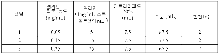
근육만을 표현하는 재료들 및 근육, 지방, 및 피부를 표현하는 재료들로 구성된 팬텀들이 본 명세서에 기재된 센서들 중 예시적인 센서 및 광섬유 프로브 모두를 이용하여 동시에 측정되었다. 단-거리 소스에 의해 생성된 입사 복사의 강도를 감소시키기 위해 센서의 단-거리 소스에 중립 밀도 필터가 부착되었다. 센서에 대하여 선택된 단-거리 및 장-거리 소스들 각각의 출력 복사 강도들은 각각의 소스 내의 LED들 각각에 인가된 구동 전류들을 제어함으로써 조절되었다. 각각의 LED에 대하여 최대 구동 전류의 퍼센트로서 표현되는, 단-거리 소스 LED들에 인가된 구동 전류들은 하기와 같다: 735㎚, 17%; 780㎚, 5%; 810㎚, 2%; 850㎚, 2%; 890㎚, 2%; 및 940㎚, 2%. 각각의 LED에 대하여 최대 구동 전류의 퍼센트로서 표현된, 장-거리 소스 LED들에 인가된 구동 전류들은 하기와 같다: 735㎚, 35%; 780㎚, 15%; 810㎚, 15%; 850㎚, 15%; 890㎚, 15%; 및 940㎚, 15%.Phantoms composed of muscle-only materials and muscle, fat, and skin-expressing materials were simultaneously measured using both the exemplary sensor and fiber optic probes of the sensors described herein. A neutral density filter was attached to the short-range source of the sensor to reduce the intensity of the incident radiation produced by the short-range source. The output radiation intensities of each of the short-range and long-range sources selected for the sensor were adjusted by controlling the drive currents applied to each of the LEDs in each source. The drive currents applied to the short-range source LEDs, expressed as a percentage of the maximum drive current for each LED, are as follows: 735 nm, 17%; 780 nm, 5%; 810 nm, 2%; 850 nm, 2%; 890 nm, 2%; And 940 nm, 2%. The drive currents applied to the long-range source LEDs, expressed as a percentage of maximum drive current for each LED, are as follows: 735 nm, 35%; 780 nm, 15%; 810 nm, 15%; 850 nm, 15%; 890 nm, 15%; And 940 nm, 15%.
센서 및 광섬유 프로브를 이용하여 측정들을 착수하기 이전에, 센서 및 프로브의 단-거리 및 장-거리 소스들 모두는 위에서 논의된 바와 같이 99%, 50%, 및 2% SPECTRALON® 반사율 표준들에 대하여 정정되었다. 측정 획득 시간들은 가능한 한 센서의 검출기 상에서 많은 강도 카운트들을 달성하도록 선택된다. 모든 참조 및 샘플 스펙트럼들은 스펙트럼들에 기반하여 추가적인 계산들을 수행하기에 앞서 상기 획득 시간들에 따라 정규화되었다.Prior to undertaking measurements using sensors and fiber optic probes, both short-range and long-range sources of the sensor and probe were tested for 99%, 50%, and 2% SPECTRALON ® reflectance standards as discussed above. Corrected. Measurement acquisition times are chosen to achieve as many intensity counts as possible on the detector of the sensor. All reference and sample spectra were normalized according to the acquisition times before performing further calculations based on the spectra.
광섬유 프로브 및 센서 모두를 이용한 삼-층 팬텀들로부터의 스펙트럼들의 측정 및 정규화에 뒤따라서, 상기 스펙트럼들은 각각의 측정된 팬텀 내에서 잉크 농도를 예측하기 위해 부분최소자승법(PLS : partial least squares method)들을 이용하여 분석되었다. 각각의 세트 내의 스펙트럼들의 총 개수는 90이었다. 장-거리 스펙트럼들은 앤더슨의 방법(예컨대, Yang 등에 의해 저술된 "Simultaneous correction of skin color and fat thickness for tissue spectroscopy using a two-distance fiber optic probe and orthogonalization technique"(Optics Letters 30: 2269-2271(2005년)), 및 미국 특허 번호 7,532,919호 참조, 각각의 전체 콘텐츠가 참조에 의해 통합됨)에 따라 단-거리 스펙트럼들을 이용하여 직교화되었다. 다음으로, 상기 직교화된 스펙트럼들은 필요하다면 PCALC에 의해 프로세싱되었고, 교차 검증을 이용한 PLS 모델이 계산되었다. 모든 스펙트럼들 및 농도들은 평균이 중심에 왔다(mean centered). 교차 검증 방법은 모든 스펙트럼들이 예측될 때까지 각각의 패스에서 모든 샘플 스펙트럼들 중 20%의 랜덤 그룹들을 배제시키는 것을 포함했다. 모든 스펙트럼들의 교차 검증은 20번 반복들 동안에 반복되었고 평균된 결과들이 보고되었다. 모델 계산들은 교차-검증의 표준 오차(RMSECV : root mean-square error of cross-validation) 값들 및 평균된 상관 계수(R2)를 획득하기 위해 네 번 반복되었다.Following the measurement and normalization of the spectra from the three-layer phantoms using both fiber optic probes and sensors, the spectra are partially least squares (PLS) methods for predicting ink concentration within each measured phantom. Were analyzed using the The total number of spectra in each set was 90. Long-range spectra are described by Anderson's method (e.g., "Simultaneous correction of skin color and fat thickness for tissue spectroscopy using a two-distance fiber optic probe and orthogonalization technique" (Optics Letters 30: 2269-2271 (2005). Year)), and US Pat. No. 7,532,919, the entire contents of each being incorporated by reference) orthogonalized using short-range spectra. Next, the orthogonalized spectra were processed by PCALC if necessary, and a PLS model using cross validation was calculated. All spectra and concentrations were mean centered. The cross validation method involved excluding 20% of random groups of all sample spectra in each pass until all spectra were predicted. Cross-validation of all spectra was repeated for 20 iterations and averaged results were reported. Model calculations were repeated four times to obtain the root mean-square error of cross-validation (RMSECV) values and the averaged correlation coefficient (R 2 ).
샘플 스펙트럼들의 잔차도들이 스펙트럼 이상 후보들에 대하여, Q 잔차(residual)들, 호텔링(Hotelling) T2 잔차들, Y 스튜던트 잔차(Studentized residual)들, 및 레버리지 플롯들을 이용하여 검사되었다. 스펙트럼들 및 PLS 모델 사이에 피트(fit)의 결핍을 식별하기 위해 Q 잔차들이 사용되었다. 측정된 농도 및 예측된 농도 사이에 큰 차이들을 갖는 스펙트럼들을 식별하기 위해 Y 스튜던트 잔차들이 사용되었다. 호텔링 T2 잔차들 및 레버리지 플롯들이 개별 스펙트럼 및 다른 스펙트럼들 사이의 차이들을 식별하기 위해 사용되었다. 샘플들의 나머지의 잔차들보다 훨씬 더 큰 잔차들을 갖는 샘플이 측정 에러를 표시하기 위해 취해졌다.Residual plots of sample spectra were examined using Q residuals, Hotelling T 2 residuals, Y Studentized residuals, and leverage plots for spectral anomaly candidates. Q residuals were used to identify the lack of fit between the spectra and the PLS model. Y Student residuals were used to identify spectra with large differences between the measured and predicted concentrations. Hoteling T 2 residuals and leverage plots were used to identify differences between the individual spectra and other spectra. A sample with much larger residuals than the rest of the samples was taken to indicate a measurement error.
전술된 분석은 상이한 프리-프로세싱을 이용한 스펙트럼들 및 두 개의 상이한 기구들(예컨대, 두 개의 상이한 센서들)을 이용하여 측정된 스펙트럼들에 대하여 반복되었다. 기구들 사이의 RMSECV 차이들이 통계적으로 유의한지의 여부를 결정하기 위해, 농도 잔차들의 형식적인 통계적 분석이 PCALC 이후 스펙트럼들의 직교화된 세트(앤더슨 직교화)에 대하여 수행되었다. 사용된 방법은 각각의 분광기로부터 두 개의 그룹들로 조직화된 각각의 샘플 스펙트럼에 대한 농도 잔차들의 두-방식의 고정 효과들 ANOVA 테스트였다. 잔차들은 특정한 샘플 및 기구에 대한 평균 값과 상기 샘플 및 기구에 대하여 측정된 값들 사이의 차이들의 제곱으로서 계산되었다. 상기 두 개의 세트들로부터의 이상 샘플들이 각각의 그룹 내의 동등한 샘플 개수들(83)을 보장하기 위해 분석 이전에 세트들 모두로부터 제거되었다.The above-described analysis was repeated for spectra using different pre-processings and spectra measured using two different instruments (eg, two different sensors). To determine whether RMSECV differences between instruments are statistically significant, a formal statistical analysis of concentration residuals was performed on an orthogonalized set of spectra (Anderson orthogonalization) after PCALC. The method used was a two-way fixed effects ANOVA test of concentration residuals for each sample spectrum organized into two groups from each spectrometer. Residuals were calculated as the square of the differences between the mean value for a particular sample and instrument and the values measured for that sample and instrument. Abnormal samples from the two sets were removed from all sets prior to analysis to ensure equivalent sample numbers 83 in each group.
광섬유 프로브로 측정된 스펙트럼들에 대한 PLS 분석으로부터의 결과들이 표 4에 도시된다. PCALC 프리프로세싱을 적용하는 것은 일반적으로 R2 및 RMSECV 값들에 의해 측정된 바와 같은 농도 예측을 향상시키는 것으로 보인다. 직교화가 PCALC 프리프로세싱보다 결과들의 향상에 더욱 기여하는 것으로 보였다. 팬텀들의 이러한 세트에 대하여 직교화가 피부 및 지방 층들로부터 스펙트럼 간섭을 제거시키거나 감소시키는 반면에 PCALC는 감소된 산재 계수에서의 변화들로부터 발생하는 근육 층으로부터 발생한 스펙트럼 변화들을 감소시킨다. 조사된 팬텀들은 단 두 개의 상이한 감소된 산재 계수들을 포함했고, 상기 상이한 계수들의 값들은 여전히 비교적 가까웠다.The results from the PLS analysis on the spectra measured with the fiber optic probes are shown in Table 4. Applying PCALC preprocessing generally appears to improve concentration prediction as measured by R 2 and RMSECV values. Orthogonality appeared to contribute more to the improvement of results than PCALC preprocessing. For this set of phantoms orthogonalization removes or reduces spectral interference from the skin and fat layers, while PCALC reduces spectral changes resulting from the muscle layer resulting from changes in the reduced scatter coefficient. The phantoms examined included only two different reduced scattering coefficients, and the values of the different coefficients were still relatively close.

조사된 팬텀들에서, 먹물에 의한 입사 복사의 강한 흡광도는 조사될 수 있는 농도 범위를 제한시킨다. 그 결과, 연구에서 상이한 팬텀들 사이의 농도 차이들은 비교적 작았다(예컨대, 0.0055, 0.0060, 0.0065, 0.0070, 및 0.0075%가 사용되었다). 이러한 작은 농도 차이들에 기인한 스펙트럼 변화들은 근육 및 지방 층들 내의 입사 복사의 산재와 같은 다른 인자들에 기인한 변화들에 대한 규모에 있어서 비교될만 할 수 있다. 부가하여, 먹물은 근적외선 구역에서 잘 정의된 스펙트럼 흡광도 피크들을 갖지 않는다; 따라서, 먹물의 스펙트럼 기여는 먹물로부터의 산재 기여와 콘볼빙된다. 유사한 문제점들은, 잘-정의된 흡광도 피크들을 갖고 헤모글로빈 스펙트럼들에서의 농도-유도된 변화들이 쉽게 식별되는 인간 테스트 대상들에 대해서 발생하지 않는다.In irradiated phantoms, the strong absorbance of incident radiation by the ink ink limits the concentration range that can be irradiated. As a result, concentration differences between different phantoms in the study were relatively small (eg, 0.0055, 0.0060, 0.0065, 0.0070, and 0.0075% were used). Spectral changes due to these small concentration differences can only be compared in scale for changes due to other factors such as the scattering of incident radiation in the muscle and fat layers. In addition, the ink does not have well defined spectral absorbance peaks in the near infrared region; Thus, the spectral contribution of the ink is convolved with the scatter contribution from the ink. Similar problems do not occur for human test subjects with well-defined absorbance peaks and concentration-induced changes in hemoglobin spectra are easily identified.

표 5는 센서로 측정된 스펙트럼들에 대한 PLS 분석으로부터의 결과들을 나타낸다. 표 4에서와 같이, 표 5의 데이터는 스펙트럼들의 PCALC 프리프로세싱이 센서로 측정된 스펙트럼들에 대하여 스펙트럼 직교화와 같이 향상된 예측 결과들을 제공하는 것을 나타낸다. 신뢰도 레벨 α=0.05에 대한 ANOVA 결과들은 0.769의 p-값을 나타냈고, 유사(그러나 상이한) 센서들에 대한 RMSECV 사이의 차이들이 통계적으로 유의하지 않다는 것이 표시된다.Table 5 shows the results from the PLS analysis on the spectra measured with the sensor. As in Table 4, the data in Table 5 shows that PCALC preprocessing of the spectra provides enhanced prediction results such as spectral orthogonalization for the spectra measured with the sensor. The ANOVA results for confidence level α = 0.05 showed a p-value of 0.769, indicating that the differences between RMSECVs for similar (but different) sensors are not statistically significant.
인간 테스트 대상들 상에서 광섬 유 프로브 및 센서의 성능 사이의 차이들을 검사하기 위해, 테스트 대상들의 그룹은 두 개의 별도 경우들 상에서 동일 테스트 프로토콜에 종속된다. 연구실에 대한 첫 번째 방문시, 각각의 대상은 심장수축기 혈압에 걸쳐서 90㎜에서의 커프스(cuff) 폐색을 포함했고 폐색을 이용한 1분의 주먹쥐기 운동이 뒤따른 테스트 프로토콜을 겪었다. 반사율 스펙트럼들은 광섬유 프로브를 이용하여 측정되었다. 연구실에 대한 두 번째 방문 동안에(적어도 48시간 이후), 각각의 대상은 동일한 프로토콜을 겪었고, 반사율 스펙트럼들은 센서로 측정되었다.To examine the differences between the performance of the optical fiber probe and sensor on human test subjects, the group of test subjects is subject to the same test protocol on two separate cases. On the first visit to the laboratory, each subject underwent a test protocol followed by cuff occlusion at 90 mm across the systolic blood pressure and followed by a minute fist movement using the obstruction. Reflectance spectra were measured using a fiber optic probe. During the second visit to the lab (after at least 48 hours), each subject underwent the same protocol, and the reflectance spectra were measured with a sensor.
센서는 위에서 논의된 바와 같이 세 개의 상이한 반사율 표준들에 대하여 매일 조정되었다. 센서는 의학용 등급 접착제로 각각의 대상의 심지굴근(flexor digitorum profundus)에 부착되었다. 스펙트럼들은 매 30초마다 측정되었고, 근육 산소 포화도는 전체 프로토콜을 통틀어, 예컨대 Yang 등에 의해 저술된 "Quantitative measurement of muscle oxygen saturation without influence from skin and fat using continuous-wave near infrared spectroscopy"(Optics Express 15: 13715-13730(2007년))에 기재된 방법들을 이용하여 계산되었고, 그 전체 콘텐츠는 본 명세서에 참조에 의해 통합된다. 상이한 대상들로부터의 결과들을 비교하기 위해, 연구에서의 네 번의 시점들이 식별되었고, 시점들 각각에서의 대상들 전부에 대한 근육 산소 포화도 값들이 평균되었다. 식별된 시점들은 하기와 같다: 기준선(폐색 이전 최종 3분); 폐색(주먹쥐기 운동 이전 최종 3분); 운동(1분 주먹쥐기 운동 및 폐색); 및 회복(폐색이 릴리스된 이후 첫 3분). 각각의 시점에서 광섬유 프로브 및 센서에 의해 결정된 근육 산소 포화도의 값들은 유의한 것으로 간주된 p<0.05를 갖는 한 쌍의 t-테스트를 이용하여 비교되었다.The sensor was adjusted daily for three different reflectance standards as discussed above. The sensor was attached to the flexor digitorum profundus of each subject with a medical grade adhesive. Spectra were measured every 30 seconds and muscle oxygen saturation was measured throughout the entire protocol, such as "Quantitative measurement of muscle oxygen saturation without influence from skin and fat using continuous-wave near infrared spectroscopy" (Optics Express 15: 13715-13730 (2007), the entire contents of which are incorporated herein by reference. To compare the results from different subjects, four time points in the study were identified, and muscle oxygen saturation values for all of the subjects at each of the time points were averaged. The identified time points were as follows: baseline (last 3 minutes before occlusion); Occlusion (last 3 minutes before fist movement); Exercise (one minute fist movement and occlusion); And recovery (first 3 minutes since occlusion was released). The values of muscle oxygen saturation determined by the fiber optic probe and sensor at each time point were compared using a pair of t-tests with p <0.05 considered significant.
광섬유 프로브 및 센서에 대한 근육 산소 포화도 결과들이 표 6 및 도 29에 도시된다. 상기 테스트 프로토콜의 모든 단계에서, 광섬유 프로브 및 센서로부터 획득된 측정 결과들은 유사하며, 센서가 다양한 애플리케이션들에서 광섬유 프로브에 대한 적절한 교체물이라는 것이 표시된다.Muscle oxygen saturation results for fiber optic probes and sensors are shown in Table 6 and FIG. 29. At all stages of the test protocol, the measurement results obtained from the optical fiber probe and sensor are similar, indicating that the sensor is a suitable replacement for the optical fiber probe in various applications.

측정된 스펙트럼들은 또한 근육 pH를 결정하기 위해 센서를 사용하는 것의 실행가능성을 조사하는데 사용되었다. 통상적으로, 근육 pH를 계산하기 위한 방법은 근육 산소 포화도를 계산하기 위해 사용된 방법보다 반사율 스펙트럼들을 획득하기 위해 사용된 광학 시스템에 따라 더욱 강하게 좌우된다. 근육 pH는 광섬유 프로브에 대하여 개발된 부분최소자승법 모델을 이용하여 측정된 스펙트럼들로부터 계산된다(예컨대, Soller 등에 의해 저술된 "Noninvasive determination of exercise-induced hydrogen ion threshold through direct optical measurement"( 응용 생리학 저널 104: 837-844(2008년)) 참조, 그 전체 콘텐츠는 본 명세서에 참조에 의해 통합됨). 광섬유 프로브 및 센서로 측정된 스펙트럼들에서의 작은 차이들은 상기 프로브에 대하여 개발된 PLS 모델 공식들이 센서로 수집된 스펙트럼들에 직접 적용될 수 없다는 것에 충분히 유의적이었다. The measured spectra were also used to investigate the feasibility of using the sensor to determine muscle pH. Typically, the method for calculating muscle pH depends more strongly on the optical system used to obtain reflectance spectra than the method used to calculate muscle oxygen saturation. Muscle pH is calculated from the spectra measured using a partial least-squares model developed for fiber optic probes (eg, "Noninvasive determination of exercise-induced hydrogen ion threshold through direct optical measurement" by Soller et al., Journal of Applied Physiology 104: 837-844 (2008), the entire contents of which are incorporated herein by reference). Small differences in the spectra measured with the fiber optic probe and sensor were sufficiently significant that the PLS model formulas developed for the probe could not be directly applied to the spectra collected with the sensor.
센서로 측정된 스펙트럼들에 대하여 직접적으로 근육 pH 모델들을 개발하는 실행가능성을 조사하기 위해, 광섬유 프로브를 이용하여 개발된 pH 값들은, 테스트 프로토콜 내의 대응하는 시점들에서 센서를 이용하여 측정된 스펙트럼들에 대하여, PLS 모델 개발에 대한 "알려진" pH 값들로서 사용되었다. 센서를 이용하여 측정된 스펙트럼들은 직교화되었고, 이상(outlier)들은 제거되었다. 모델 정확성은 5번의 데이터 분할들 및 20번 반복들을 이용한 "랜덤 서브세트들" 교차-검증으로 평가되었다. 각각의 별도 테스트 대상에 대하여 모델이 개발되었다.In order to investigate the feasibility of developing muscle pH models directly on the spectra measured with the sensor, the pH values developed using the fiber optic probe are measured with the sensor at the corresponding points in the test protocol. For, it was used as "known" pH values for PLS model development. Spectra measured using the sensor were orthogonalized and outliers were removed. Model accuracy was assessed by "random subsets" cross-validation with 5 data partitions and 20 iterations. A model was developed for each separate test subject.

여섯 명의 테스트 대상들 각각에 대한 정확성 메트릭들이 표 7에 도시된다. 각각의 모델에 대한 R2 값들은 모델의 추세 능력의 표시를 제공하고, RMSECV 값들은 각각의 모델의 정확성의 추정치들을 제공한다. 도 30은 테스트 대상들 중 한 명에 대한 알려진 근육 pH 값 및 계산된 근육 pH 값 사이의 관련성을 나타낸다. 일반적으로, 테스트 대상들 중에서, R2 값은 높고 RMSECV 값들은 측정된 pH의 범위(6.9-7.5)와 비교할 때 낮다. 이러한 결과들은 혈관 폐색 동안의 토끼 근육에서의 pH 측정 전극들을 이용하여 획득된 데이터와 비교될만한다(예컨대, Zhang 등에 의해 저술된 "Partial least-squares modeling of near-infrared reflectance data for noninvasive in vivo determination of deep-tissue pH"(응용 분광학 52: 400-406(1998년))을 참조, 그 전체 콘텐츠가 참조에 의해 본 명세서에 통합됨). 토끼 스펙트럼들이 근조직으로부터 직접 획득된 반면에, 본 연구에서는 피부 및 지방의 층들을 통과해 근조직을 조명하고 모델 개발에 앞서 상기 피부 및 지방 층들로부터의 기여들을 감소시키거나 제거시키기 위해 측정된 스펙트럼들을 정정함으로써 근육 스펙트럼들이 획득되었다. 이는, 추가로, 본 명세서에 기재된 센서들이 반사율 스펙트럼들을 측정하기 위해 사용된 광학 어레인지먼트에 비교적 민감한 파라미터들을 포함하는 폭넓게 다양한 생리학적 파라미터들의 정확한 추정치들을 획득하는데 사용될 수 있다는 것을 제안한다.Accuracy metrics for each of the six test subjects are shown in Table 7. The R 2 values for each model provide an indication of the model's trend capability and the RMSECV values provide estimates of the accuracy of each model. 30 shows the relationship between known muscle pH values and calculated muscle pH values for one of the test subjects. In general, among the test subjects, the R 2 value is high and the RMSECV values are low compared to the range of measured pH (6.9-7.5). These results are comparable with data obtained using pH measurement electrodes in rabbit muscle during vascular occlusion (eg, "Partial least-squares modeling of near-infrared reflectance data for noninvasive in vivo determination, as described by Zhang et al. of deep-tissue pH "(Application Spectroscopy 52: 400-406 (1998)), the entire contents of which are incorporated herein by reference). While rabbit spectra were obtained directly from muscle tissue, this study corrects the measured spectra to illuminate muscle tissue through layers of skin and fat and to reduce or eliminate contributions from the skin and fat layers prior to model development. Thereby muscle spectra were obtained. This further suggests that the sensors described herein can be used to obtain accurate estimates of a wide variety of physiological parameters, including parameters that are relatively sensitive to the optical arrangement used to measure reflectance spectra.
다른 Other 실시예들Examples
다수의 실시예들이 기재되었다. 그럼에도 불구하고, 다양한 수정들이 본 기재의 사상 및 범위로부터 벗어나지 않고도 이루어질 수 있다는 것이 이해될 것이다. 따라서, 다른 실시예들은 하기의 청구범위의 범위 내에 있다.A number of embodiments have been described. Nevertheless, it will be understood that various modifications may be made without departing from the spirit and scope of the present disclosure. Accordingly, other embodiments are within the scope of the following claims.
Claims (30)
전자 프로세서를 포함하는 회로 기판(circuit board);
다수의 복사 소스(radiation source)들 ― 각각의 소스는 상기 회로 기판에 부착됨 ―; 및
상기 회로 기판에 부착된 스펙트럼 검출기 ― 상기 스펙트럼 검출기는 상기 다수의 복사 소스들 중 하나 이상으로부터 도출된 복사를 분석하도록 구성됨 ― 를 포함하며,
사용 동안에, 상기 센서는 대상(subject)의 몸체의 일부분 상에 착용되도록 구성되고,
상기 전자 프로세서는, 상기 다수의 복사 소스들 중 둘 이상의 복사 소스들이 입사 복사(incident radiation)를 상기 대상으로 지향(direct)시키도록 하고, 상기 스펙트럼 검출기가 상기 대상으로부터의 복사를 분석하도록 하고, 상기 대상으로부터의 상기 복사에 기반하여 상기 대상의 하나 이상의 특성들을 결정하도록 구성되는, 센서.As a sensor,
A circuit board comprising an electronic processor;
Multiple radiation sources, each source attached to the circuit board; And
A spectrum detector attached to the circuit board, the spectrum detector configured to analyze radiation derived from one or more of the plurality of radiation sources;
During use, the sensor is configured to be worn on a portion of the body of the subject,
The electronic processor causes two or more radiation sources of the plurality of radiation sources to direct incident radiation to the object, the spectrum detector to analyze radiation from the object, and And determine one or more characteristics of the subject based on the radiation from the subject.
상기 전자 프로세서는 상기 입사 복사를 생성하기 위해 상기 복사 소스들 중 적어도 하나를 선택적으로 조절하도록 구성되는, 센서.The method of claim 1,
The electronic processor is configured to selectively adjust at least one of the radiation sources to generate the incident radiation.
상기 전자 프로세서는 선택된 스펙트럼 형태를 갖는 입사 복사를 생성하기 위해, (ⅰ) 상기 복사 소스들 각각의 듀티 사이클(duty cycle) 및 (ⅱ) 상기 복사 소스들 각각에 공급되는 전기 구동 전류 중 적어도 하나를 선택적으로 조절하도록 구성되는, 센서.The method of claim 2,
The electronic processor generates at least one of (i) a duty cycle of each of the radiation sources and (ii) an electrical drive current supplied to each of the radiation sources to produce an incident radiation having a selected spectral form. And configured to selectively adjust.
상기 복사 소스들은 상기 검출기로부터 9㎜ 이하의 거리에 포지셔닝된(positioned) 단-거리 소스 및 상기 검출기로부터 10㎜ 이상의 거리에 각각 포지셔닝된 적어도 두 개의 장-거리 소스들을 포함하는, 센서.The method of claim 1,
Wherein the radiation sources comprise a short-distance source positioned at a distance of 9 mm or less from the detector and at least two long-distance sources each positioned at a distance of 10 mm or more from the detector.
상기 복사 소스들은 적어도 두 개의 단-거리 소스들 및 적어도 세 개의 장-거리 소스들을 포함하는, 센서.The method of claim 1,
And the radiation sources comprise at least two short-range sources and at least three long-range sources.
상기 전자 프로세서는 상기 입사 복사의 적어도 일부분을 생성하기 위해, 상기 장-거리 소스들 각각에 의해 생성된 입사 복사를 통해 상기 대상을 조명(illuminate)하고 상기 장-거리 소스들 각각에 의한 조명에 대응하는 상기 대상의 흡광도(absorbance) 스펙트럼을 측정하고 상기 장-거리 소스들 중 하나를 선택하기 위해 상기 측정된 흡광도 스펙트럼들을 비교함으로써, 상기 장-거리 소스들 중 하나를 선택하도록 구성되는, 센서.The method of claim 4, wherein
The electronic processor illuminates the object and corresponds to illumination by each of the long-distance sources via an incident radiation generated by each of the long-range sources to produce at least a portion of the incident radiation. And select one of the long-range sources by measuring an absorbance spectrum of the object and comparing the measured absorbance spectra to select one of the long-range sources.
상기 비교하는 것은,
상기 장-거리 소스들 각각에 대하여, 상기 장-거리 소스에 대응하는 흡광도 스펙트럼을 상기 대상의 흡광도 스펙트럼에 대한 테일러 시리즈(Taylor series) 모델에 피팅(fitting)시키고, 상기 흡광도 스펙트럼 및 상기 모델 사이의 평균 에러를 결정하는 것; 및
상기 흡광도 스펙트럼 및 상기 모델 사이의 최소 평균 에러에 대응하는 장-거리 소스를 선택하는 것을 포함하는, 센서.The method according to claim 6,
Compared above,
For each of the long-range sources, an absorbance spectrum corresponding to the long-range source is fitted to a Taylor series model for the absorbance spectrum of the subject, and between the absorbance spectrum and the model Determining mean error; And
Selecting a long-distance source corresponding to the minimum mean error between the absorbance spectrum and the model.
상기 비교하는 것은,
상기 장-거리 소스들에 대응하는 상기 흡광도 스펙트럼들을 피팅시키기에 앞서, 상기 대상 내의 피부 및 지방의 층들에 기인한 스펙트럼 효과들을 감소시키기 위해, 상기 대상을 상기 단-거리 소스로부터의 복사에 노출시킴으로써 획득된 흡광도 스펙트럼으로부터 도출된 정보를 이용하여, 상기 장-거리 소스들에 대응하는 상기 흡광도 스펙트럼들 각각을 정정하는 것을 더 포함하는, 센서.The method of claim 7, wherein
Compared above,
Prior to fitting the absorbance spectra corresponding to the long-range sources, the subject is exposed to radiation from the short-range source to reduce spectral effects due to layers of skin and fat in the subject. And correcting each of the absorbance spectra corresponding to the long-range sources using information derived from the obtained absorbance spectra.
상기 장-거리 소스를 선택하는 것은,
상기 선택된 장-거리 소스가 최소 적절성 기준(minimum suitability criterion)을 충족시키는지의 여부를 결정하는 것을 더 포함하는, 센서.The method of claim 7, wherein
Selecting the long-distance source,
And determining whether the selected long-range source meets a minimum suitability criterion.
상기 선택된 장-거리 소스가 최소 적절성 기준을 충족시키는지의 여부를 결정하는 것은, 모델 피팅 에러들의 평균 값(μ) 및 표준편차(σ)를 결정하는 것을 포함하며,
상기 전자 프로세서는 상기 모델 및 상기 선택된 장-거리 소스에 대응하는 흡광도 스펙트럼 사이의 평균 에러가 인터벌(μ-3σ, μ+3σ) 내에 있다면 상기 장-거리 소스를 선택하도록 구성되는, 센서.The method of claim 9,
Determining whether the selected long-distance source meets the minimum adequacy criterion includes determining an average value (μ) and standard deviation (σ) of model fitting errors,
The electronic processor is configured to select the long-distance source if the mean error between the model and the absorbance spectrum corresponding to the selected long-distance source is within an interval (μ-3σ, μ + 3σ).
상기 복사 소스들은 둘 이상의 단-거리 소스들을 포함하고,
상기 전자 프로세서는,
상기 단-거리 소스들 각각에 의해 생성된 입사 복사를 통해 상기 대상을 조명하고;
상기 단-거리 소스들 각각에 대응하는 흡광도 스펙트럼들을 측정하고;
상기 단-거리 소스들에 대응하는 스펙트럼들 각각을 이용하여 상기 장-거리 소스들에 대응하는 스펙트럼들 각각을 정정하고;
상기 정정된 스펙트럼들을 상기 대상의 흡광도 스펙트럼에 대한 테일러 시리즈 모델에 피팅시키고, 상기 정정된 스펙트럼들 각각 및 상기 모델 사이의 피팅 에러를 결정하고; 그리고
상기 정정된 스펙트럼들 중에서 최소 피팅 에러에 대응하는 단-거리 소스 및 장-거리 소스를 포함하는 조합을 식별함으로써,
상기 입사 복사의 적어도 일부분을 생성하기 위해 단-거리 소스 및 장-거리 소스의 조합을 선택하도록 구성되는, 센서.The method of claim 10,
The radiation sources include two or more short-range sources,
The electronic processor,
Illuminate the object via incident radiation produced by each of the short-range sources;
Measure absorbance spectra corresponding to each of the short-range sources;
Correct each of the spectra corresponding to the long-range sources using each of the spectra corresponding to the short-range sources;
Fitting the corrected spectra to a Taylor series model for the absorbance spectra of the subject, and determining a fitting error between each of the corrected spectra and the model; And
By identifying a combination comprising a short-range source and a long-range source corresponding to a minimum fitting error among the corrected spectra,
And select a combination of short-range and long-range sources to produce at least a portion of the incident radiation.
디스플레이 유닛을 더 포함하며,
상기 디스플레이 유닛은 상기 입사 복사가 상기 다수의 복사 소스들에 의해 방출되는 표면의 반대편에 있는 상기 센서의 표면 상에 포지셔닝되고,
상기 디스플레이 유닛은 상기 대상의 상기 하나 이상의 특성들 중 적어도 일부의 값들과 상기 대상의 상기 하나 이상의 특성들의 앞서 측정된 값들을 디스플레이하도록 구성되는, 센서.The method of claim 1,
Further comprising a display unit,
The display unit is positioned on the surface of the sensor opposite the surface from which the incident radiation is emitted by the plurality of radiation sources,
The display unit is configured to display values of at least some of the one or more characteristics of the object and previously measured values of the one or more characteristics of the object.
상기 센서로 그리고 상기 센서로부터 데이터를 전송하도록 구성되는 무선 전송기 및 수신기를 포함하는 통신 인터페이스를 더 포함하며,
상기 센서는 상기 데이터를 네트워크를 통해 전송하도록 구성되는, 센서.The method of claim 1,
Further comprising a communication interface comprising a wireless transmitter and receiver configured to transmit data to and from the sensor,
The sensor is configured to transmit the data over a network.
상기 하나 이상의 특성들은 상기 대상의 산소 포화도(oxygen saturation), 산소 분압(oxygen tension), pH, 헤마토그리트(hematocrit), 헤모글로빈 농도(hemoglobin concentration), 무산소 임계치(anaerobic threshold), 수분 함량(water content), 및 산소 소비량(oxygen consumption) 중 적어도 하나를 포함하는, 센서.The method of claim 1,
The one or more properties may include oxygen saturation, oxygen tension, pH, hematocrit, hemoglobin concentration, anaerobic threshold, water content of the subject. And at least one of oxygen consumption.
상기 전자 프로세서는 상기 대상으로부터의 상기 복사의 분석 동안에 넌-제로(non-zero) 측정된 검출기 신호 강도를 신호 강도들의 미리 결정된 범위 내에서 유지시키도록 구성되는, 센서.The method of claim 1,
And the electronic processor is configured to maintain a non-zero measured detector signal strength within a predetermined range of signal intensities during analysis of the radiation from the subject.
상기 검출기 신호 강도를 미리 결정된 범위 내에서 유지시키는 것은,
상기 신호 강도를 제어하기 위해 상기 검출기의 전자 이득 및 신호 획득 시간 중 적어도 하나를 조절하는 것을 포함하는, 센서.The method of claim 15,
Maintaining the detector signal strength within a predetermined range,
Adjusting at least one of an electronic gain and a signal acquisition time of the detector to control the signal strength.
상기 검출기 신호 강도를 미리 결정된 범위 내에서 유지시키는 것은,
입사 복사를 상기 대상으로 지향시키기 위해 상기 다수의 복사 소스들 중 상이한 복사 소스를 선택하는 것을 포함하는, 센서.The method of claim 15,
Maintaining the detector signal strength within a predetermined range,
Selecting a different one of said plurality of radiation sources to direct incident radiation to said object.
상기 다수의 복사 소스들 중 상이한 복사 소스를 선택하는 것은,
상기 검출기로부터 10㎜ 이상의 거리에 포지셔닝된 복사 소스들 중에서 상이한 복사 소스를 선택하는 것을 포함하는, 센서.The method of claim 17,
Selecting a different copy source of the plurality of copy sources,
And selecting a different radiation source among radiation sources positioned at a distance of at least 10 mm from the detector.
상기 다수의 복사 소스들 중 상이한 복사 소스를 선택하는 것은,
상기 검출기로부터 9㎜ 이하의 거리에 포지셔닝된 복사 소스들 중에서 상이한 복사 소스를 선택하는 것을 포함하는, 센서.The method of claim 17,
Selecting a different copy source of the plurality of copy sources,
And selecting a different radiation source among radiation sources positioned at a distance of 9 mm or less from the detector.
상기 전자 프로세서는 치료용 디바이스(therapeutic device)를 제어하기 위해 상기 대상의 상기 하나 이상의 특성들에 관한 정보를 상기 치료용 디바이스에 제공하도록 구성되는, 센서.The method of claim 1,
The electronic processor is configured to provide the therapeutic device with information regarding the one or more characteristics of the subject to control a therapeutic device.
샘플에 직접 부착되고 상기 샘플에 부착될 때 상기 샘플의 적어도 일부분에 대응하는 형태를 추정하도록 구성된 접착 표면을 포함하는 연성 장착 멤버(flexible mounting member); 및
상기 장착 멤버에 부착된 전자 프로세서, 다수의 복사 소스들 및 스펙트럼 검출기를 포함하며,
상기 전자 프로세서는 상기 복사 소스들 중 적어도 두 개의 복사 소스들이 입사 복사를 샘플로 지향시키도록 하고, 상기 스펙트럼 검출기가 상기 샘플로부터의 복사를 분석하도록 하고, 상기 샘플로부터의 상기 복사에 기반하여 상기 샘플의 하나 이상의 특성들을 결정하도록 구성되는, 센서.As a sensor,
A flexible mounting member comprising an adhesive surface attached directly to the sample and configured to estimate a shape corresponding to at least a portion of the sample when attached to the sample; And
An electronic processor attached to the mounting member, a plurality of radiation sources, and a spectral detector,
The electronic processor causes at least two of the radiation sources to direct incident radiation to a sample, the spectral detector to analyze the radiation from the sample, and based on the radiation from the sample And determine one or more characteristics of the sensor.
상기 장착 멤버는 상기 샘플과 접촉하는 제1 일회용(disposable) 부분과, 상기 다수의 복사 소스들, 상기 검출기, 및 상기 전자 프로세서가 부착되는 제2 비-일회용 부분을 포함하고, 상기 일회용 부분은 근적외선 복사에 적어도 부분적으로 투과적이고 윈도우 ― 상기 복사 소스들에 의해 생성된 입사 복사가 상기 샘플에 도달하기 위해 상기 윈도우를 통과함 ― 를 형성하는, 센서.The method of claim 21,
The mounting member includes a first disposable portion in contact with the sample and a second non-disposable portion to which the plurality of radiation sources, the detector, and the electronic processor are attached, the disposable portion being near infrared And at least partially transparent to radiation and forming a window, wherein incident radiation produced by the radiation sources passes through the window to reach the sample.
상기 하나 이상의 특성들은 상기 샘플의 산소 분압, 산소 포화도, pH, 헤마토그리트, 헤모글로빈 농도, 무산소 임계치, 수분 함량, 및 산소 소비량 중 적어도 하나를 포함하는, 센서.The method of claim 21,
The one or more characteristics include at least one of oxygen partial pressure, oxygen saturation, pH, hematogrit, hemoglobin concentration, anoxic threshold, moisture content, and oxygen consumption of the sample.
다수의 복사 소스들 중 하나를 선택하는 단계;
상기 선택된 소스로부터의 복사를 상기 샘플 상으로 입사하도록 지향시키는 단계;
상기 샘플로부터의 복사를 검출하는 단계;
상기 검출된 복사에 기반하여 상기 하나 이상의 샘플 특성들을 결정하는 단계를 포함하며,
상기 선택하는 단계는,
상기 다수의 복사 소스들 중 각각의 복사 소스에 대하여, 상기 샘플을 상기 복사 소스로부터의 복사에 노출시킴으로써 상기 샘플의 흡광도 스펙트럼을 측정하는 단계;
상기 흡광도 스펙트럼들을 상기 샘플의 흡광도에 대한 모델에 피팅시키고, 상기 모델에 대하여, 각각의 스펙트럼에 대한 평균 피팅 에러를 결정하는 단계; 및
최소 평균 피트 에러를 갖는 스펙트럼에 대응하는 소스를 선택하는 단계를 포함하는, 하나 이상의 샘플 특성들을 측정하기 위한 방법.A method for measuring one or more sample characteristics, the method comprising:
Selecting one of the plurality of copy sources;
Directing radiation from the selected source to be incident on the sample;
Detecting radiation from the sample;
Determining the one or more sample characteristics based on the detected radiation,
The selecting step,
For each of the plurality of radiation sources, measuring an absorbance spectrum of the sample by exposing the sample to radiation from the radiation source;
Fitting the absorbance spectra to a model for absorbance of the sample and determining, for the model, an average fitting error for each spectrum; And
Selecting a source corresponding to a spectrum having a minimum mean pit error.
상기 선택하는 단계는,
상기 평균 피팅 에러들을 결정하기에 앞서, 상기 샘플 내의 피부 및 지방 층들에 기인한 스펙트럼 효과들을 감소시키기 위해, 상기 흡광도 스펙트럼들 각각을 정정하는 단계를 더 포함하는, 하나 이상의 샘플 특성들을 측정하기 위한 방법.The method of claim 24,
The selecting step,
Prior to determining the average fitting errors, further comprising correcting each of the absorbance spectra to reduce spectral effects due to skin and fat layers in the sample. .
상기 선택하는 단계는,
상기 피팅 에러들에 관련된 평균 값 μ 및 표준편차 값 σ을 결정하는 단계; 및
소스를 선택하는 단계 ― 상기 소스에 대응하는 흡광도 스펙트럼으로부터 결정된 평균 피팅 에러는 인터벌(μ-3σ, μ+3σ) 내에 있음 ― 를 포함하는, 하나 이상의 샘플 특성들을 측정하기 위한 방법.The method of claim 24,
The selecting step,
Determining a mean value μ and a standard deviation value σ related to the fitting errors; And
Selecting a source, wherein the mean fitting error determined from the absorbance spectra corresponding to the source is within an interval (μ-3σ, μ + 3σ).
상기 샘플로부터의 복사의 검출 동안에, 검출된 복사 신호의 강도를 0보다 더 크고 신호 강도들의 미리 결정된 범위 내에 있도록 유지시키는 단계를 더 포함하는, 하나 이상의 샘플 특성들을 측정하기 위한 방법.The method of claim 24,
During detection of radiation from the sample, further comprising maintaining the intensity of the detected radiation signal to be greater than zero and within a predetermined range of signal intensities.
상기 신호 강도를 미리 결정된 범위 내에서 유지시키는 단계는,
상기 검출기의 전자 이득 및 신호 획득 시간 ― 상기 신호 획득 시간 동안에 상기 복사가 상기 신호 강도를 제어하기 위해 검출됨 ― 중 적어도 하나를 조절하는 단계를 포함하는, 하나 이상의 샘플 특성들을 측정하기 위한 방법.The method of claim 27,
Maintaining the signal strength within a predetermined range,
Adjusting at least one of the electronic gain and signal acquisition time of the detector, wherein the radiation is detected to control the signal strength during the signal acquisition time.
상기 신호 강도를 미리 결정된 범위 내에서 유지시키는 단계는,
복사를 상기 샘플로 지향시키기 위해 상기 다수의 복사 소스들 중 상이한 복사 소스를 선택하는 단계를 포함하는, 하나 이상의 샘플 특성들을 측정하기 위한 방법.The method of claim 27,
Maintaining the signal strength within a predetermined range,
Selecting a different one of said plurality of radiation sources to direct radiation to said sample.
상기 하나 이상의 샘플 특성들은 상기 샘플의 산소 포화도, 산소 분압, pH, 헤마토그리트, 헤모글로빈 농도, 무산소 임계치, 수분 함량, 및 산소 소비량 중 적어도 하나를 포함하는, 하나 이상의 샘플 특성들을 측정하기 위한 방법.The method of claim 24,
Wherein the one or more sample characteristics comprise at least one of oxygen saturation, oxygen partial pressure, pH, hematogrit, hemoglobin concentration, anoxic threshold, moisture content, and oxygen consumption of the sample.
Applications Claiming Priority (2)
| Application Number | Priority Date | Filing Date | Title |
|---|---|---|---|
| US8708408P | 2008-08-07 | 2008-08-07 | |
| US61/087,084 | 2008-08-07 |
Publications (1)
| Publication Number | Publication Date |
|---|---|
| KR20110053993A true KR20110053993A (en) | 2011-05-24 |
Family
ID=42153472
Family Applications (1)
| Application Number | Title | Priority Date | Filing Date |
|---|---|---|---|
| KR1020117005389A KR20110053993A (en) | 2008-08-07 | 2009-08-07 | Spectroscopic sensors |
Country Status (7)
| Country | Link |
|---|---|
| US (1) | US9095291B2 (en) |
| EP (2) | EP2323554B1 (en) |
| JP (1) | JP5671460B2 (en) |
| KR (1) | KR20110053993A (en) |
| CN (1) | CN102176864B (en) |
| CA (1) | CA2732996A1 (en) |
| WO (1) | WO2010053617A2 (en) |
Cited By (2)
| Publication number | Priority date | Publication date | Assignee | Title |
|---|---|---|---|---|
| KR20150042261A (en) * | 2012-08-10 | 2015-04-20 | 바이압틱스 인코포레이티드 | Wireless, Handheld, Tissue Oximetry Device |
| KR20180128063A (en) * | 2016-04-20 | 2018-11-30 | 바이압틱스 인코포레이티드 | Oxygen measurement probe with electronically selectable tissue depth analysis |
Families Citing this family (100)
| Publication number | Priority date | Publication date | Assignee | Title |
|---|---|---|---|---|
| US6850788B2 (en) | 2002-03-25 | 2005-02-01 | Masimo Corporation | Physiological measurement communications adapter |
| US7459713B2 (en) | 2003-08-14 | 2008-12-02 | Microptix Technologies, Llc | Integrated sensing system approach for handheld spectral measurements having a disposable sample handling apparatus |
| AU2006241076B2 (en) | 2005-04-25 | 2011-11-24 | University Of Massachusetts | Systems and methods for correcting optical reflectance measurements |
| US8840549B2 (en) | 2006-09-22 | 2014-09-23 | Masimo Corporation | Modular patient monitor |
| US11903682B2 (en) * | 2007-02-27 | 2024-02-20 | J&M Shuler, Inc. | Method and system for monitoring oxygenation levels of a compartment for detecting conditions of a compartment syndrome |
| KR101530233B1 (en) * | 2007-07-13 | 2015-06-19 | 유니버시티 오브 매사추세츠 | Physical Performance Monitoring and Monitors |
| CA2732996A1 (en) | 2008-08-07 | 2010-05-14 | University Of Massachusetts | Spectroscopic sensors |
| FR2939199B1 (en) * | 2008-12-02 | 2011-02-11 | C2 Diagnostics | METHOD AND DEVICE FOR FLOW CYTOMETRY WITHOUT SAGING FLUID |
| WO2010085954A1 (en) * | 2009-01-29 | 2010-08-05 | Leo Pharma A/S | A method for determining the state of a skin disorder using near infrared (nir) spectroscopy |
| US8463346B2 (en) * | 2009-06-10 | 2013-06-11 | Medtronic, Inc. | Absolute calibrated tissue oxygen saturation and total hemoglobin volume fraction |
| US20110208015A1 (en) | 2009-07-20 | 2011-08-25 | Masimo Corporation | Wireless patient monitoring system |
| US9153112B1 (en) | 2009-12-21 | 2015-10-06 | Masimo Corporation | Modular patient monitor |
| WO2011091280A2 (en) | 2010-01-22 | 2011-07-28 | University Of Massachusetts | Methods and systems for analyte measurement |
| US20130317367A1 (en) * | 2010-05-04 | 2013-11-28 | Michael Simms Shuler | Method and system for providing versatile nirs sensors |
| JP5796275B2 (en) * | 2010-06-02 | 2015-10-21 | セイコーエプソン株式会社 | Spectrometer |
| US20120166117A1 (en) | 2010-10-29 | 2012-06-28 | Xia Llc | Method and apparatus for evaluating superconducting tunnel junction detector noise versus bias voltage |
| EP2635185A4 (en) * | 2010-11-03 | 2014-12-24 | Univ Washington Through Its Ct For Com Ization | Determination of tissue oxygenation in vivo |
| US20120184831A1 (en) * | 2011-01-18 | 2012-07-19 | Radiation Monitoring Devices, Inc. | Systems, devices and methods for monitoring hemodynamics |
| WO2012115210A1 (en) * | 2011-02-23 | 2012-08-30 | 国立大学法人静岡大学 | Optical measurement device |
| WO2013023071A1 (en) | 2011-08-11 | 2013-02-14 | Reflectance Medical, Inc. | Patient interface for reusable optical sensor |
| US9943269B2 (en) | 2011-10-13 | 2018-04-17 | Masimo Corporation | System for displaying medical monitoring data |
| JP6104920B2 (en) | 2011-10-13 | 2017-03-29 | マシモ・コーポレイション | Medical surveillance hub |
| US10149616B2 (en) | 2012-02-09 | 2018-12-11 | Masimo Corporation | Wireless patient monitoring device |
| CN102579237B (en) * | 2012-03-08 | 2014-03-12 | 北京龙马负图科技有限公司 | Intermittent pneumatic compression system with venous refilling detecting function |
| US20130237848A1 (en) * | 2012-03-12 | 2013-09-12 | Gary P. Warren | Geometry of a Transcutaneous Sensor |
| WO2013165380A2 (en) * | 2012-04-30 | 2013-11-07 | Empire Technology Development, Llc | Infrared guide stars for endoscopic orienteering |
| WO2013166461A1 (en) | 2012-05-03 | 2013-11-07 | Vioptix, Inc. | Tissue oximetry probe geometry for robust calibration and self-correction |
| CN103536291B (en) * | 2012-07-10 | 2017-04-19 | 花王株式会社 | Body surface sebum distribution testing method |
| US9749232B2 (en) | 2012-09-20 | 2017-08-29 | Masimo Corporation | Intelligent medical network edge router |
| EP3821796A1 (en) * | 2012-09-27 | 2021-05-19 | ivWatch, LLC | Systems and methods for mitigating the effects of tissue blood volume changes to aid in diagnosing infiltration or extravasation in animalia tissue |
| FR2999334B1 (en) * | 2012-12-07 | 2015-01-09 | Sp3H | METHOD AND INSPECTIVE DEVICE FOR ANALYZING FLUID IN A THERMAL ENGINE |
| RU2015127030A (en) | 2012-12-07 | 2017-01-13 | Спзх | ON-BOARD DEVICE AND METHOD FOR ANALYSIS OF A FLUID IN A HEAT ENGINE |
| FR2999333A1 (en) * | 2012-12-07 | 2014-06-13 | Sp3H | Method for controlling spectrometer to analyze e.g. hydrocarbons used as fuel of heat engine in e.g. terrestrial vehicle, involves adjusting integration duration of photosensitive cells to determined value of integration duration |
| JP6396324B2 (en) * | 2013-01-04 | 2018-09-26 | ユニバーシティ オブ リメリック | Differential infrared nanomicroscopy system and method |
| CA2867138C (en) * | 2013-01-22 | 2021-03-02 | Ivwatch, Llc | Geometry of a transcutaneous sensor |
| KR101709032B1 (en) * | 2013-02-01 | 2017-02-23 | 서지 브이. 몬로스 | Hydrogen on-demand fuel system for internal combustion engines |
| US9733155B2 (en) * | 2013-02-01 | 2017-08-15 | Serge V. Monros | On-board diesel emissions diagnostic and monitoring system |
| US9518920B2 (en) | 2013-06-26 | 2016-12-13 | Alentic Microscience Inc. | Sample processing improvements for microscopy |
| US10502666B2 (en) * | 2013-02-06 | 2019-12-10 | Alentic Microscience Inc. | Sample processing improvements for quantitative microscopy |
| US9996954B2 (en) | 2013-10-03 | 2018-06-12 | Covidien Lp | Methods and systems for dynamic display of a trace of a physiological parameter |
| KR102185362B1 (en) * | 2013-10-08 | 2020-12-02 | 삼성전자주식회사 | Ultrasonic probe and medical apparatus including the same |
| US10832818B2 (en) | 2013-10-11 | 2020-11-10 | Masimo Corporation | Alarm notification system |
| CN103605394B (en) * | 2013-10-28 | 2015-04-01 | 上海思源电力电容器有限公司 | Intelligent capacitance regulator |
| CN103610467B (en) * | 2013-11-05 | 2016-08-03 | 李鲁亚 | Parallel near infrared light electrical sensor apparatus and animal organ's tissue detection System and method for |
| WO2015070162A2 (en) * | 2013-11-08 | 2015-05-14 | University Of Houston System | Imaging system for intra-operative and post-operative blood perfusion monitoring |
| JP2017506376A (en) | 2013-11-29 | 2017-03-02 | モティヴ・インコーポレーテッドMotiv Inc. | Wearable computing device |
| US10098576B2 (en) * | 2014-03-14 | 2018-10-16 | Covidien Lp | Regional saturation shock detection method and system |
| USD763938S1 (en) | 2014-04-02 | 2016-08-16 | Cephalogics, LLC | Optical sensor array |
| USD763939S1 (en) | 2014-04-02 | 2016-08-16 | Cephalogics, LLC | Optical sensor array liner with optical sensor array pad |
| CH709493A2 (en) * | 2014-04-14 | 2015-10-15 | Fondarex Sa | Apparatus and method for measuring the moisture in die casting molds. |
| WO2016025430A1 (en) * | 2014-08-11 | 2016-02-18 | The Board Of Trustees Of The University Of Illinois | Epidermal photonic systems and methods |
| US9844341B2 (en) | 2014-08-14 | 2017-12-19 | Zoll Medical Corporation | Patient interface for reusable optical sensor |
| JP6428052B2 (en) * | 2014-08-26 | 2018-11-28 | セイコーエプソン株式会社 | Biological information acquisition apparatus and electronic device |
| JP6606817B2 (en) * | 2014-09-26 | 2019-11-20 | セイコーエプソン株式会社 | measuring device |
| WO2016069862A1 (en) | 2014-10-29 | 2016-05-06 | Zoll Medical Corporation | Measuring myocardial physiologic parameters |
| EP3243444A4 (en) * | 2015-01-07 | 2018-09-19 | National Institute of Advanced Industrial Science and Technology | Brain function measurement device and brain function measurement method |
| US10617347B2 (en) | 2015-03-24 | 2020-04-14 | Zoll Medical Corporation | Using pH and SMO2 from a spectral sensor as an indication of subject down time |
| US10799177B2 (en) * | 2015-03-24 | 2020-10-13 | Zoll Medical Corporation | Estimation of adipose tissue with a modified near infrared spectral sensor |
| EP3283990B1 (en) | 2015-04-15 | 2023-10-25 | NIKE Innovate C.V. | Activity monitoring device with assessment of exercise intensity |
| WO2016196295A1 (en) | 2015-05-29 | 2016-12-08 | Nike Innovate C.V. | Activity monitoring device with assessment of exercise intensity |
| KR102612874B1 (en) | 2015-08-31 | 2023-12-12 | 마시모 코오퍼레이션 | Wireless patient monitoring systems and methods |
| JP6547188B2 (en) | 2015-09-17 | 2019-07-24 | 国立大学法人名古屋大学 | Photosensitivity tester |
| US20180344219A1 (en) * | 2015-09-23 | 2018-12-06 | Koninklijke Philips N.V. | Multi color pulse oximeter |
| US10349875B2 (en) | 2015-09-30 | 2019-07-16 | Zoll Medical Corporation | Non-invasive assessment of physiological parameters of tissue via near infrared spectroscopy to distinguish between arrhythmic and asphyxial arrest |
| US10638960B2 (en) | 2015-10-26 | 2020-05-05 | Reveal Biosensors, Inc. | Optical physiologic sensor methods |
| EP3189782A1 (en) | 2016-01-08 | 2017-07-12 | Oxy4 GmbH | Device and method for the continuous non-invasive determination of physiologic parameters of a test subject |
| JP2019512364A (en) * | 2016-03-03 | 2019-05-16 | ダイノメトリックス インコーポレイテッド ディー/ビー/エー ヒューモン | Tissue oxygen saturation detection and related devices and methods |
| US10722158B2 (en) | 2016-04-20 | 2020-07-28 | Vioptix, Inc. | Handheld oximeter probe with replaceable probe tip |
| TWI765885B (en) | 2016-04-21 | 2022-06-01 | 美商菲歐普提斯公司 | Method and device for determining tissue oxygen saturation with melanin correction |
| US10786187B2 (en) | 2016-04-22 | 2020-09-29 | Vioptix, Inc. | Determining tissue oxygen saturation with quality reporting |
| TWI754641B (en) | 2016-04-22 | 2022-02-11 | 美商菲歐普提斯公司 | Oximeter device and oximeter system having the same |
| CN109313295B (en) * | 2016-06-03 | 2021-10-08 | 3M创新有限公司 | Optical filter with spatially varying microreplicated layer |
| US10617302B2 (en) | 2016-07-07 | 2020-04-14 | Masimo Corporation | Wearable pulse oximeter and respiration monitor |
| JP7146733B2 (en) | 2016-07-18 | 2022-10-04 | ビオプティックス・インコーポレイテッド | Oxygen measurement device with laparoscopic dilation |
| KR102592509B1 (en) * | 2016-07-21 | 2023-10-20 | 삼성전자주식회사 | Wearable device and charger, and light absorbance estimation method |
| US10768497B2 (en) * | 2016-10-03 | 2020-09-08 | Xerox Corporation | Hyperspectral imaging system |
| WO2018071715A1 (en) | 2016-10-13 | 2018-04-19 | Masimo Corporation | Systems and methods for patient fall detection |
| DE102016123846A1 (en) * | 2016-12-08 | 2018-06-14 | Visus Health It Gmbh | Detector tape for X-ray film |
| DE102017101271B4 (en) * | 2017-01-24 | 2020-07-30 | Osram Opto Semiconductors Gmbh | SENSOR FOR DETECTING A HEART RATE AND / OR A BLOOD OXYGEN CONTENT AND METHOD FOR OPERATING A SENSOR |
| JP2018165737A (en) * | 2017-03-28 | 2018-10-25 | 富士通株式会社 | Drive circuit and image projection device |
| MX2020008534A (en) * | 2018-02-15 | 2020-09-18 | Regeneron Pharma | Systems and methods for failure mode detection in process chromatography. |
| US20210000391A1 (en) * | 2018-03-27 | 2021-01-07 | Well Being Digital Limited | A method of selecting the intensity of a light source for monitoring an analyte in blood, and a device thereof |
| EP3782165A1 (en) | 2018-04-19 | 2021-02-24 | Masimo Corporation | Mobile patient alarm display |
| EP4134003A1 (en) * | 2018-05-01 | 2023-02-15 | Whoop, Inc. | Tissue oxygen saturation detection and related apparatus |
| US11331017B2 (en) * | 2019-02-13 | 2022-05-17 | Viavi Solutions Inc. | Calibration-free pulse oximetry |
| KR102244675B1 (en) * | 2019-04-26 | 2021-04-26 | 연세대학교 산학협력단 | Mobile device sensor platform with transcutaneous oxygen partial pressure sensor |
| US11589764B1 (en) | 2019-10-30 | 2023-02-28 | Brigham Young University | Methods and devices for aligning miniaturized spectrometers and impedance sensors in wearable devices |
| US11877845B1 (en) | 2019-10-30 | 2024-01-23 | Brigham Young University | Miniaturized spectrometers on transparent substrates |
| US11471078B1 (en) | 2019-10-30 | 2022-10-18 | Brigham Young University | Miniaturized spectrometers for wearable devices |
| US11630316B1 (en) | 2019-10-30 | 2023-04-18 | Brigham Young University | Miniaturized collimators |
| WO2021142469A1 (en) | 2020-01-10 | 2021-07-15 | Vioptix, Inc. | Medical device with stability measurement reporting |
| US11051729B1 (en) * | 2020-01-17 | 2021-07-06 | Capmet, Inc. | Oxygen saturation measuring device, probe adapted to be used therefor, and oxygen saturation measuring method |
| US20210290177A1 (en) | 2020-03-20 | 2021-09-23 | Masimo Corporation | Wearable device for monitoring health status |
| USD980091S1 (en) | 2020-07-27 | 2023-03-07 | Masimo Corporation | Wearable temperature measurement device |
| USD974193S1 (en) | 2020-07-27 | 2023-01-03 | Masimo Corporation | Wearable temperature measurement device |
| CN112258367A (en) * | 2020-11-13 | 2021-01-22 | 珠海大横琴科技发展有限公司 | Monitoring processing method and device |
| US20220193320A1 (en) * | 2020-12-23 | 2022-06-23 | Fresenius Medical Care Holdings, Inc. | Blood monitoring system for detecting occult hemorrhages |
| KR20230147199A (en) * | 2021-02-25 | 2023-10-20 | 윌리엄 유엔 | integrated sports training |
| USD1000975S1 (en) | 2021-09-22 | 2023-10-10 | Masimo Corporation | Wearable temperature measurement device |
| WO2023222742A1 (en) | 2022-05-19 | 2023-11-23 | Trinamix Gmbh | Spectral sensing device and method for determining at least one item of spectral information |
Family Cites Families (36)
| Publication number | Priority date | Publication date | Assignee | Title |
|---|---|---|---|---|
| US5020112A (en) * | 1989-10-31 | 1991-05-28 | At&T Bell Laboratories | Image recognition method using two-dimensional stochastic grammars |
| JPH0686780A (en) * | 1992-09-09 | 1994-03-29 | Hitachi Ltd | Living body optical measuring instrument |
| WO1994012096A1 (en) * | 1992-12-01 | 1994-06-09 | Somanetics Corporation | Patient sensor for optical cerebral oximeters |
| US5477853A (en) * | 1992-12-01 | 1995-12-26 | Somanetics Corporation | Temperature compensation method and apparatus for spectroscopic devices |
| US5363843A (en) * | 1993-03-16 | 1994-11-15 | Yousef Daneshvar | Special instrument covers |
| JPH06319723A (en) * | 1993-05-13 | 1994-11-22 | Omron Corp | Motion monitor device |
| US5497769A (en) * | 1993-12-16 | 1996-03-12 | I.S.S. (Usa) Inc. | Photosensor with multiple light sources |
| US5582170A (en) | 1994-12-01 | 1996-12-10 | University Of Massachusetts Medical Center | Fiber optic sensor for in vivo measurement of nitric oxide |
| DE19506484C2 (en) * | 1995-02-24 | 1999-09-16 | Stiftung Fuer Lasertechnologie | Method and device for selective non-invasive laser myography (LMG) |
| TW302435B (en) | 1995-05-12 | 1997-04-11 | Ciba Geigy Ag | |
| US5813403A (en) | 1995-11-08 | 1998-09-29 | Soller; Babs R. | Optical measurement of tissue pH |
| JP3790030B2 (en) | 1997-10-30 | 2006-06-28 | コーリンメディカルテクノロジー株式会社 | Reflective photoelectric pulse wave detector |
| US6006119A (en) * | 1998-02-04 | 1999-12-21 | Polestar Technologies, Inc. | Non-invasive optical measurement of blood hematocrit |
| US20020091324A1 (en) * | 1998-04-06 | 2002-07-11 | Nikiforos Kollias | Non-invasive tissue glucose level monitoring |
| US7047054B2 (en) * | 1999-03-12 | 2006-05-16 | Cas Medical Systems, Inc. | Laser diode optical transducer assembly for non-invasive spectrophotometric blood oxygenation monitoring |
| TW453862B (en) * | 1999-08-30 | 2001-09-11 | Cas Medical Systems Inc | Near infrared spectrophotometric monitoring assembly for non-invasive monitoring of blood oxygenation levels in a subjects's body |
| US6564088B1 (en) | 2000-01-21 | 2003-05-13 | University Of Massachusetts | Probe for localized tissue spectroscopy |
| US6640117B2 (en) * | 2000-09-26 | 2003-10-28 | Sensys Medical, Inc. | Method and apparatus for minimizing spectral effects attributable to tissue state variations during NIR-based non-invasive blood analyte determination |
| WO2002069796A2 (en) | 2001-03-01 | 2002-09-12 | University Of Massachusetts | Correction of spectra for subject diversity |
| WO2003032808A2 (en) | 2001-10-15 | 2003-04-24 | University Of Massachusetts | Tissue oxygen measurement system |
| US20040005717A1 (en) | 2002-06-11 | 2004-01-08 | Umass/Worcester | Methods for non-invasive measurement of blood electrolyte concentration |
| US7459713B2 (en) * | 2003-08-14 | 2008-12-02 | Microptix Technologies, Llc | Integrated sensing system approach for handheld spectral measurements having a disposable sample handling apparatus |
| US7245373B2 (en) | 2004-04-26 | 2007-07-17 | University Of Massachusetts | Spectrometer system for optical reflectance measurements |
| US7881892B2 (en) | 2005-01-21 | 2011-02-01 | University Of Massachusetts | Standardization methods for correcting spectral differences across multiple spectroscopic instruments |
| US8055321B2 (en) * | 2005-03-14 | 2011-11-08 | Peter Bernreuter | Tissue oximetry apparatus and method |
| AU2006241076B2 (en) | 2005-04-25 | 2011-11-24 | University Of Massachusetts | Systems and methods for correcting optical reflectance measurements |
| US7419402B2 (en) | 2005-08-10 | 2008-09-02 | Deutsch Engineered Connecting Devices, Inc. | Backshell device for a connector |
| JP2007105316A (en) * | 2005-10-14 | 2007-04-26 | Konica Minolta Sensing Inc | Bioinformation measuring instrument |
| US20070282178A1 (en) * | 2006-04-12 | 2007-12-06 | Weinmann Gerate Fur Medizin Gmbh & Co. Kg | Method and device for the identification of at least one substance of content of a body fluid |
| CN101489482B (en) * | 2006-05-30 | 2012-01-18 | 马萨诸塞大学 | Measuring tissue oxygenation |
| US8098376B2 (en) | 2006-09-07 | 2012-01-17 | William Marsh Rice University | Integrated embedded processor based laser spectroscopic sensor |
| US8068890B2 (en) * | 2006-09-29 | 2011-11-29 | Nellcor Puritan Bennett Llc | Pulse oximetry sensor switchover |
| JP2007196001A (en) * | 2007-03-16 | 2007-08-09 | Hitachi Medical Corp | Optical measuring device for living body |
| KR101530233B1 (en) * | 2007-07-13 | 2015-06-19 | 유니버시티 오브 매사추세츠 | Physical Performance Monitoring and Monitors |
| CA2732996A1 (en) | 2008-08-07 | 2010-05-14 | University Of Massachusetts | Spectroscopic sensors |
| WO2011091280A2 (en) | 2010-01-22 | 2011-07-28 | University Of Massachusetts | Methods and systems for analyte measurement |
-
2009
- 2009-08-07 CA CA2732996A patent/CA2732996A1/en not_active Abandoned
- 2009-08-07 EP EP09825161.4A patent/EP2323554B1/en active Active
- 2009-08-07 US US13/057,617 patent/US9095291B2/en active Active
- 2009-08-07 WO PCT/US2009/053183 patent/WO2010053617A2/en active Application Filing
- 2009-08-07 EP EP19157953.1A patent/EP3556291A1/en active Pending
- 2009-08-07 CN CN200980139542.4A patent/CN102176864B/en active Active
- 2009-08-07 JP JP2011522286A patent/JP5671460B2/en active Active
- 2009-08-07 KR KR1020117005389A patent/KR20110053993A/en not_active Application Discontinuation
Cited By (2)
| Publication number | Priority date | Publication date | Assignee | Title |
|---|---|---|---|---|
| KR20150042261A (en) * | 2012-08-10 | 2015-04-20 | 바이압틱스 인코포레이티드 | Wireless, Handheld, Tissue Oximetry Device |
| KR20180128063A (en) * | 2016-04-20 | 2018-11-30 | 바이압틱스 인코포레이티드 | Oxygen measurement probe with electronically selectable tissue depth analysis |
Also Published As
| Publication number | Publication date |
|---|---|
| CN102176864B (en) | 2014-12-31 |
| US9095291B2 (en) | 2015-08-04 |
| CN102176864A (en) | 2011-09-07 |
| WO2010053617A2 (en) | 2010-05-14 |
| CA2732996A1 (en) | 2010-05-14 |
| EP2323554B1 (en) | 2019-02-20 |
| JP5671460B2 (en) | 2015-02-18 |
| JP2011530351A (en) | 2011-12-22 |
| EP2323554A4 (en) | 2014-03-26 |
| WO2010053617A3 (en) | 2010-07-08 |
| EP3556291A1 (en) | 2019-10-23 |
| EP2323554A2 (en) | 2011-05-25 |
| US20110205535A1 (en) | 2011-08-25 |
Similar Documents
| Publication | Publication Date | Title |
|---|---|---|
| US9095291B2 (en) | Spectroscopic sensors | |
| US11890095B2 (en) | Tissue oximetry probe geometry for robust calibration and self-correction | |
| ES2747822T3 (en) | Medical device | |
| JP6548639B2 (en) | Optical physiological sensor and assembling method | |
| US20130096401A1 (en) | Wireless disposable shock trauma monitoring device | |
| JP2004081427A (en) | Apparatus for measuring water content in living body | |
| US20210204824A1 (en) | A device for measuring blood pressure | |
| WO2008029978A1 (en) | Non-invasive measuring apparatus of subcutaneous fat thickness and method thereof | |
| EP2211692B1 (en) | Method and instrument for the non-invasive measurement of the oxygenation/saturation of biological tissue | |
| KR102290329B1 (en) | Smart biological measurement system | |
| US20220333986A1 (en) | Determining a level of oxygenation of one or more cells | |
| US20240081699A1 (en) | Wireless tissue oxygenation monitoring device | |
| CN114259229A (en) | Multi-parameter vital sign monitoring device and method |
Legal Events
| Date | Code | Title | Description |
|---|---|---|---|
| E601 | Decision to refuse application |