KR20110044940A - Mold system for changing the depth of the cardboard-based container - Google Patents
Mold system for changing the depth of the cardboard-based container Download PDFInfo
- Publication number
- KR20110044940A KR20110044940A KR1020107013407A KR20107013407A KR20110044940A KR 20110044940 A KR20110044940 A KR 20110044940A KR 1020107013407 A KR1020107013407 A KR 1020107013407A KR 20107013407 A KR20107013407 A KR 20107013407A KR 20110044940 A KR20110044940 A KR 20110044940A
- Authority
- KR
- South Korea
- Prior art keywords
- core
- mold
- mold cavity
- container
- cardboard
- Prior art date
Links
Images


Classifications
-
- B—PERFORMING OPERATIONS; TRANSPORTING
- B31—MAKING ARTICLES OF PAPER, CARDBOARD OR MATERIAL WORKED IN A MANNER ANALOGOUS TO PAPER; WORKING PAPER, CARDBOARD OR MATERIAL WORKED IN A MANNER ANALOGOUS TO PAPER
- B31B—MAKING CONTAINERS OF PAPER, CARDBOARD OR MATERIAL WORKED IN A MANNER ANALOGOUS TO PAPER
- B31B50/00—Making rigid or semi-rigid containers, e.g. boxes or cartons
- B31B50/59—Shaping sheet material under pressure
-
- B—PERFORMING OPERATIONS; TRANSPORTING
- B29—WORKING OF PLASTICS; WORKING OF SUBSTANCES IN A PLASTIC STATE IN GENERAL
- B29C—SHAPING OR JOINING OF PLASTICS; SHAPING OF MATERIAL IN A PLASTIC STATE, NOT OTHERWISE PROVIDED FOR; AFTER-TREATMENT OF THE SHAPED PRODUCTS, e.g. REPAIRING
- B29C45/00—Injection moulding, i.e. forcing the required volume of moulding material through a nozzle into a closed mould; Apparatus therefor
- B29C45/14—Injection moulding, i.e. forcing the required volume of moulding material through a nozzle into a closed mould; Apparatus therefor incorporating preformed parts or layers, e.g. injection moulding around inserts or for coating articles
- B29C45/14336—Coating a portion of the article, e.g. the edge of the article
-
- B—PERFORMING OPERATIONS; TRANSPORTING
- B29—WORKING OF PLASTICS; WORKING OF SUBSTANCES IN A PLASTIC STATE IN GENERAL
- B29C—SHAPING OR JOINING OF PLASTICS; SHAPING OF MATERIAL IN A PLASTIC STATE, NOT OTHERWISE PROVIDED FOR; AFTER-TREATMENT OF THE SHAPED PRODUCTS, e.g. REPAIRING
- B29C45/00—Injection moulding, i.e. forcing the required volume of moulding material through a nozzle into a closed mould; Apparatus therefor
-
- B—PERFORMING OPERATIONS; TRANSPORTING
- B31—MAKING ARTICLES OF PAPER, CARDBOARD OR MATERIAL WORKED IN A MANNER ANALOGOUS TO PAPER; WORKING PAPER, CARDBOARD OR MATERIAL WORKED IN A MANNER ANALOGOUS TO PAPER
- B31F—MECHANICAL WORKING OR DEFORMATION OF PAPER, CARDBOARD OR MATERIAL WORKED IN A MANNER ANALOGOUS TO PAPER
- B31F1/00—Mechanical deformation without removing material, e.g. in combination with laminating
-
- B—PERFORMING OPERATIONS; TRANSPORTING
- B65—CONVEYING; PACKING; STORING; HANDLING THIN OR FILAMENTARY MATERIAL
- B65D—CONTAINERS FOR STORAGE OR TRANSPORT OF ARTICLES OR MATERIALS, e.g. BAGS, BARRELS, BOTTLES, BOXES, CANS, CARTONS, CRATES, DRUMS, JARS, TANKS, HOPPERS, FORWARDING CONTAINERS; ACCESSORIES, CLOSURES, OR FITTINGS THEREFOR; PACKAGING ELEMENTS; PACKAGES
- B65D1/00—Containers having bodies formed in one piece, e.g. by casting metallic material, by moulding plastics, by blowing vitreous material, by throwing ceramic material, by moulding pulped fibrous material, by deep-drawing operations performed on sheet material
- B65D1/34—Trays or like shallow containers
-
- B—PERFORMING OPERATIONS; TRANSPORTING
- B29—WORKING OF PLASTICS; WORKING OF SUBSTANCES IN A PLASTIC STATE IN GENERAL
- B29C—SHAPING OR JOINING OF PLASTICS; SHAPING OF MATERIAL IN A PLASTIC STATE, NOT OTHERWISE PROVIDED FOR; AFTER-TREATMENT OF THE SHAPED PRODUCTS, e.g. REPAIRING
- B29C45/00—Injection moulding, i.e. forcing the required volume of moulding material through a nozzle into a closed mould; Apparatus therefor
- B29C45/14—Injection moulding, i.e. forcing the required volume of moulding material through a nozzle into a closed mould; Apparatus therefor incorporating preformed parts or layers, e.g. injection moulding around inserts or for coating articles
- B29C45/14778—Injection moulding, i.e. forcing the required volume of moulding material through a nozzle into a closed mould; Apparatus therefor incorporating preformed parts or layers, e.g. injection moulding around inserts or for coating articles the article consisting of a material with particular properties, e.g. porous, brittle
-
- B—PERFORMING OPERATIONS; TRANSPORTING
- B29—WORKING OF PLASTICS; WORKING OF SUBSTANCES IN A PLASTIC STATE IN GENERAL
- B29K—INDEXING SCHEME ASSOCIATED WITH SUBCLASSES B29B, B29C OR B29D, RELATING TO MOULDING MATERIALS OR TO MATERIALS FOR MOULDS, REINFORCEMENTS, FILLERS OR PREFORMED PARTS, e.g. INSERTS
- B29K2311/00—Use of natural products or their composites, not provided for in groups B29K2201/00 - B29K2309/00, as reinforcement
- B29K2311/12—Paper, e.g. cardboard
-
- B—PERFORMING OPERATIONS; TRANSPORTING
- B29—WORKING OF PLASTICS; WORKING OF SUBSTANCES IN A PLASTIC STATE IN GENERAL
- B29K—INDEXING SCHEME ASSOCIATED WITH SUBCLASSES B29B, B29C OR B29D, RELATING TO MOULDING MATERIALS OR TO MATERIALS FOR MOULDS, REINFORCEMENTS, FILLERS OR PREFORMED PARTS, e.g. INSERTS
- B29K2711/00—Use of natural products or their composites, not provided for in groups B29K2601/00 - B29K2709/00, for preformed parts, e.g. for inserts
- B29K2711/10—Natural fibres, e.g. wool or cotton
-
- B—PERFORMING OPERATIONS; TRANSPORTING
- B31—MAKING ARTICLES OF PAPER, CARDBOARD OR MATERIAL WORKED IN A MANNER ANALOGOUS TO PAPER; WORKING PAPER, CARDBOARD OR MATERIAL WORKED IN A MANNER ANALOGOUS TO PAPER
- B31B—MAKING CONTAINERS OF PAPER, CARDBOARD OR MATERIAL WORKED IN A MANNER ANALOGOUS TO PAPER
- B31B50/00—Making rigid or semi-rigid containers, e.g. boxes or cartons
- B31B50/59—Shaping sheet material under pressure
- B31B50/592—Shaping sheet material under pressure using punches or dies
Abstract
본 발명은 판지-기반 용기 제조용 몰드 시스템(1)에 관한 것으로서; 상기 몰드 시스템은 서로 반대로 반대편에 위치되는 가동식 몰드 하프(10) 및 부동식 몰드 하프(20)를 포함하며; 상기 몰드 시스템은 판지 블랭크로부터 프레싱되는 바닥(57)과, 상기 바닥에 연결되는 벽(59), 및 플라스틱으로 적어도 부분적으로 캐스팅되고 상기 벽의 상부 에지에 연결되며 상기 벽들을 에워싸는 테두리(50)를 포함하는 용기(500)의 제조를 가능하게 하며; 상기 부동식 몰드 하프(20)와 관련하여 이동가능한 상기 가동식 몰드 하프(10)는 코어(41)가 제공된 적어도 코어 판(4)과, 상기 코어(41)와 관련하여 이동가능하고 셧-오프(shutt-off) 표면(5a)을 포함하며 상기 코어(41)를 둘러싸는 평판형 시일 링(5), 및 상기 코어(41)와 상기 시일 링(5) 사이에 위치됨으로써 상기 용기 상에 테두리(50)가 형성될 수 있게 하며 상기 시일 링(5)과 상기 코어(41)와 관련하여 이동될 수 있는 칼라 링(6)을 포함하며; 상기 부동식 몰드 하프(40)는 몰드 공동(71) 및 시일 표면(7a)이 제공된 적어도 몰드 판(7)을 포함한다. 상기 판지-기반 용기 제조용 몰드 시스템(1)에 있어서, 인서트(720)가 상기 몰드 공동(71)의 베이스(71b) 상에 지지되고 상기 베이스에 분리가능하게 부착될 수 있으며, 상기 인서트는 높이(h)만큼 상기 몰드 공동의 깊이(H)를 감소시켜서, 상기 인서트(720)의 연속적인 표면(71b')이 상기 몰드 공동의 새로운 바닥(71b')으로서 작용하며 상기 판지 블랭크의 압착 단계에서 상기 몰드 공동의 내측으로 관통하는 상기 코어(41) 부분의 길이(H)가 상기 코어 판 상의 코어(41)를 더 짧은 코어로 대체하거나, 길이가 변경되지 않는 상기 코어(41)의 베이스 부분(41F)에 길이가 변경될 수 있는 부착 부분(41f)을 분리가능하게 부착함으로써 상기 인서트의 높이(h)만큼 각각 감소될 수 있으며, 서로 대응하는 상기 코어 또는 상기 코어의 부착 부분 및 상기 몰드 공동의 베이스의 인서트(720)가 제조되는 판지 블랭크의 깊이, 즉 상기 용기 벽(59)의 상부 에지로부터 상기 판지 블랭크로부터 프레싱되는 상기 용기 바닥(57)까지의 거리를 변경하는데 사용될 수 있다.The present invention relates to a mold system (1) for making cardboard-based containers; The mold system comprises a movable mold half (10) and a floating mold half (20) located opposite each other; The mold system includes a bottom 57 pressed from a cardboard blank, a wall 59 connected to the floor, and an edge 50 at least partially cast from plastic and connected to the top edge of the wall and surrounding the walls. To enable the manufacture of a container 500 comprising; The movable mold half 10 movable in relation to the floating mold half 20 comprises at least a core plate 4 provided with a core 41 and a movable and shut-off in relation to the core 41. -off) a flat seal ring 5 comprising a surface 5a and surrounding the core 41, and a rim 50 on the container by being positioned between the core 41 and the seal ring 5. Includes a collar ring (6) which can be formed and which can be moved in relation to the seal ring (5) and the core (41); The floating mold half 40 comprises at least a mold plate 7 provided with a mold cavity 71 and a seal surface 7a. In the mold system 1 for producing cardboard-based containers, an insert 720 is supported on the base 71b of the mold cavity 71 and detachably attached to the base, the insert having a height ( h) by reducing the depth H of the mold cavity such that the continuous surface 71b 'of the insert 720 acts as a new bottom 71b' of the mold cavity and in the pressing step of the cardboard blank The length H of the portion of the core 41 penetrating inwardly of the mold cavity replaces the core 41 on the core plate with a shorter core, or the base portion 41F of the core 41 whose length does not change. By detachably attaching the attachment portion 41f, which can be changed in length, by the height h of the insert, respectively, the core or the attachment portion of the core and the base of the mold cavity corresponding to each other. Inser of The depth of the carton blank which 720 is produced, i.e., can be used to change the distance to the container bottom 57 is pressed from the cardboard blank, which continues from the upper edge of the container wall (59).
Description
본 발명은 판지-기반 용기의 깊이를 변경하기 위한 특허청구범위 제 1항의 전제부에 따른 몰드 시스템에 관한 것이며, 상기 몰드 시스템은 가동식 몰드 하프(half) 및 부동식 몰드 하프를 포함하며, 상기 몰드 하프들은 서로 반대로 위치되며, 상기 몰드 시스템은 판지 블랭크로부터 프레싱되는 바닥, 상기 바닥에 연결되는 벽들 및 플라스틱으로 적어도 부분적으로 몰딩되고 상기 벽들의 상부 에지에 연결되며 상기 벽들을 에워싸는 (플라스틱)테두리를 포함하는 용기를 제조하는데 사용될 수 있다.The present invention relates to a mold system according to the preamble of
식품 산업에 있어서, 특히 소위 트레이 팩키지(tray package)가 바닥, 상기 바닥을 감싸며 상방향으로 연장하는 벽, 및 상기 벽의 상부 에지를 감싸며 외측으로 연장하는 테두리(rim)를 갖는 뚜껑 달린 용기로 구성되는 저장 팩키지로서 사용된다. 상기 용기는 테두리에 연결된 뚜껑(lid)에 의해 폐쇄된다. 그와 같은 용기에서, 용기 바닥 및 벽의 재료는 종종 판지를 포함하며, 그 상부에는 플라스틱 및/또는 금속 층이 추가될 수 있어서 적용에 따른 판지의 스팀 및/또는 산소 투과 특성을 변경한다.In the food industry, in particular, a so-called tray package consists of a lidded container having a bottom, a wall extending upwardly surrounding the floor, and a rim extending outwardly surrounding the upper edge of the wall. It is used as a storage package. The container is closed by a lid connected to the rim. In such containers, the material of the container bottom and wall often includes cardboard, on top of which plastic and / or metal layers can be added to alter the steam and / or oxygen permeation properties of the cardboard depending on the application.
일반적으로, 그와 같은 소위 트레이 팩키지가 식품을 저장하는데 사용되며 뚜껑에 의해 밀폐된다. 뚜껑을 팩키지에 부착될 수 있게 하기 위해, 트레이 팩키지로서 사용되는 용기의 에지에는 측벽의 상단부로부터 돌출하여 팩키지를 에워싸는 수평 테두리가 제공되어야 한다. 테두리의 상부 표면 상에는 보통 적합한 코팅이 제공되어서 그에 의해 뚜껑이 팩키지에 밀착 체결될 수 있다. 예를 들어, 뚜껑 부분을 팩키지에 체결하기 위해 열-밀봉가능한(heat-sealable) 재료를 사용하는 것은 매우 일반적이다. 이들 중에서, 음식 팩키지 및 그에 사용되는 팩키지 재료의 예들은 WO 03/033258, EP 1289856, WO 00/21854, 및 US 5425972호의 특허 명세서에 설명되어 있다.Generally, such so-called tray packages are used to store food and are sealed by lids. In order to be able to attach the lid to the package, the edge of the container used as the tray package should be provided with a horizontal rim that projects from the top of the side wall to enclose the package. A suitable coating is usually provided on the upper surface of the rim so that the lid can be tightly fastened to the package. For example, it is very common to use a heat-sealable material to fasten the lid portion to the package. Among these, examples of food packages and package materials used therein are described in the patent specifications of WO 03/033258, EP 1289856, WO 00/21854, and US 5425972.
판지 블랭크(cardboard blank)로부터 프레싱되는 바닥, 상기 바닥에 연결되는 벽 및 상기 벽의 상부 에지에 연결되어 벽을 에워싸며 적어도 부분적으로 플라스틱 캐스팅되는 테두리를 포함하는, 트레이 형상을 갖는 그와 같은 용기는 다양한 방법들에 의해 형성될 수 있다. 출원 공개된 FI 20070973호에는 트레이 팩키지의 제조 방법이 설명되어 있는데, 여기서 상기 용기는 직선의 판지 블랭크로부터 몰드 시스템 내에서 임의의 형상으로 프레싱됨으로써 제조되며, 상기 몰드 시스템은 서로 반대로 위치되는 가동식 몰드 하프 및 부동식 몰드 하프를 포함하며, 상기 부동식 몰드 하프에 대해 이동가능한 가동식 몰드 하프는 코어가 제공된 코어 판과, 상기 코어에 대해 이동가능하며 시일 표면을 가지며 상기 코어를 에워싸는 판형 시일 링, 및 상기 코어와 시일 링에 대해 이동가능하며 상기 코어와 시일 링 사이에 끼워 맞춰지며 상기 용기 상에 테두리를 형성하는데 사용될 수 있는 칼라 링을 포함하며, 상기 부동식 몰드 하프는 몰드 공동 및 시일 표면이 제공된 적어도 몰드 판을 포함한다.Such a container having a tray shape, comprising a floor pressed from a cardboard blank, a wall connected to the floor, and a border connected to the top edge of the wall and enclosing the wall and at least partially plastic casting It can be formed by various methods. Application Publication FI 20070973 describes a method for manufacturing a tray package, wherein the container is manufactured by pressing in a shape in a mold system from a straight cardboard blank, the mold system being movable opposite to each other. And a floating mold half, wherein the movable mold half movable relative to the floating mold half comprises: a core plate provided with a core, a plate-shaped seal ring movable around the core and having a seal surface, and surrounding the core; A collar ring that is movable relative to the seal ring and can be used to fit between the core and the seal ring and can be used to define an edge on the container, wherein the floating mold half includes at least a mold plate provided with a mold cavity and a seal surface. Include.
그와 같은 몰드 시스템에 의해 임의의 형상으로 프레싱되는 판지 블랭크는 부동식 몰드 하프의 몰드 공동의 상부로 이송되며, 가동식 몰드 하프의 코어가 상기 몰드 공동의 내측에 안착되며, 상기 코어와 몰드 공동 사이에 남아 있는 판지 블랭크는 트레이 형상을 갖는 용기로 몰딩된다. 압착 몰딩의 말기 단계에서, 반대 표면으로부터 후방으로 상기 몰드 시스템 안쪽의 상대 표면을 이동시킴으로써 상기 테두리에 대응하는 몰드 공동을 형성하며, 그 후에 캐스팅 재료를 몰드 공동의 내측으로 유입하는 방식으로 상기 몰드가 폐쇄 상태를 유지할 때, 측방향으로 연장하는 플라스틱 재료의 테두리가 팩키지의 측벽의 상부에 몰딩된다. 상기 몰드 공동 내에서 상기 재료는 고정 테두리로 고화되며, 그 후에 상기 몰드는 개방되며 마무리된 용기 형상의 팩키지가 몰드로부터 제거된다.The cardboard blank pressed into any shape by such a mold system is transferred to the top of the mold cavity of the floating mold half, with the core of the movable mold half seated inside the mold cavity, between the core and the mold cavity. The remaining cardboard blank is molded into a container having a tray shape. In the late stage of the compression molding, the mold is formed by moving the relative surface inside the mold system from the opposite surface to the rear to form the mold cavity corresponding to the rim, and then the mold is introduced into the mold cavity in such a way as to flow into the mold cavity. When maintaining the closed state, a rim of laterally extending plastic material is molded on top of the sidewall of the package. Within the mold cavity the material solidifies to a fixed rim, after which the mold is opened and the finished container-shaped package is removed from the mold.
기본 내용으로서 전술한 종래 기술과 더불어, 본 발명의 목적은 더욱 융통성 있는 트레이 팩키지의 제조 방법을 제공하고자 하는 것이며, 동일한 몰드 시스템이 트레이 팩키지로서 사용되며 하나 또는 그보다 많은 격벽이 제공된 다양한 용기를 제조하는데 사용될 수 있으며, 또한 용기의 판지-기반 몸체에는 다양한 엠보싱 또는 상감세공 형상이 제공될 수 있다.In addition to the prior art described above as a basis, it is an object of the present invention to provide a more flexible method of manufacturing a tray package, wherein the same mold system is used as the tray package to produce various containers provided with one or more partitions. It may also be used, and the cardboard-based body of the container may also be provided with various embossing or inlay shapes.
놀랍게도, 몰드 공동 내에 놓여지는 다양한 인서트 및/또는 코어 판에 분리가능하게 부착되며 성형 코어 또는 코어들 내에 분리가능하게 놓이는 부착물에 의해 전술한 몰드 시스템의 (성형)코어 및/또는 몰드 공동을 변경함으로써 제조되는 용기의 길이가 변경될 수 있으며 깊이가 희망에 따라 변경될 수 있다는 것이 관찰되었다.Surprisingly, by modifying the (molding) core and / or mold cavity of the mold system described above by an attachment detachably attached to the various inserts and / or core plates placed in the mold cavity and releasably placed within the molding core or cores. It has been observed that the length of the vessel to be produced can be varied and the depth can be varied as desired.
더욱 엄밀하게, 본 발명은 판지-기반 용기의 깊이를 변경하기 위한 특허청구범위 제 1항에 따른 몰드 시스템에 관한 것이다. 그와 같은 몰드 시스템은 서로 반대로 위치되는 가동식 몰드 하프 및 부동식 몰드 하프를 포함하며, 상기 몰드 시스템은 판지 블랭크로부터 프레싱되는 바닥, 상기 바닥에 연결되는 벽 및 상기 벽의 상부에 연결되어 벽을 에워싸며 적어도 부분적으로 캐스팅되는 테두리를 포함하며, 상기 부동식 몰드 하프에 대해 이동가능한 가동식 몰드 하프는 코어가 제공된 코어 판과, 상기 코어에 대해 이동가능하며 시일 표면을 가지며 상기 코어를 에워싸는 판형 시일 링, 및 상기 코어와 시일 링에 대해 이동가능하며 상기 코어와 시일 링 사이에 끼워 맞춰지며 상기 용기 상에 테두리를 형성하는데 사용될 수 있는 칼라 링을 포함하며, 상기 부동식 몰드 하프는 몰드 공동 및 시일 표면이 제공된 적어도 몰드 판을 포함한다. 상기 몰드 시스템에 있어서, 인서트가 상기 몰드 공동의 베이스 상에 지지되고 베이스에 분리가능하게 부착됨으로써 그의 높이만큼 몰드 공동의 깊이를 감소시켜, 각각 인서트의 연속적인 표면이 몰드 공동의 새로운 바닥으로서 작용하며 상기 판지 블랭크의 프레싱 단계에서 몰드 공동의 내측으로 관통되는 코어 부분의 길이(H)가 단축되며, 상기 인서트의 높이(h)에 의한 상기 코어 판 내에 코어를 단축된 코어로 단축하거나 상기 코어의 베이스 부분에 분리가능하게 부착함으로써 코어의 길이가 변경되지 않고 부착물의 길이가 변경될 수 있으며, 그에 따라 서로 대응하는 상기 코어 또는 상기 코어의 부착물 및 상기 몰드 공동의 베이스의 인서트가 제조될 판지 블랭크의 깊이, 즉 상기 벽의 상부 에지로부터 상기 판지 블랭크로부터 프레싱되는 용기 바닥까지의 거리를 변경하는데 사용될 수 있다.More precisely, the present invention relates to a mold system according to
본 발명의 실시예에서, 상기 몰드 공동의 베이스에 부착되는 인서트는 용기의 판지-기반 몸체 상의 한면 또는 양면 상감세공 또는 엠보싱을 형성하는데 사용될 수 있다.In an embodiment of the invention, an insert attached to the base of the mold cavity can be used to form one or two sided inlays or embossings on the cardboard-based body of the container.
본 발명에서 베이스는 몰드 공동의 평면을 지칭하며, 이에 따라 용기가 제조되며, 용기의 깊이, 즉 테두리로부터 바닥까지의 거리가 가장 크다.In the present invention, the base refers to the plane of the mold cavity, whereby the container is made, with the greatest depth of the container, ie the distance from the edge to the bottom.
본 발명에서, 몰드 공동의 인서트의 길이 방향 및 코어의 길이 방향은 제조된 용기의 바닥에 수직한 직경을 지칭하며, 또한 이와 같이 제조된 용기의 깊이 방향도 지칭한다.In the present invention, the longitudinal direction of the insert of the mold cavity and the longitudinal direction of the core refer to a diameter perpendicular to the bottom of the produced container, and also refer to the depth direction of the container thus produced.
상기 용기 본체의 한면 상감세공 또는 엠보싱 패턴 또는 형상은 단지 상기 몸체의 하나의 표면 상에 형성되는 리세스 또는 돌출부를 지칭한다. 상기 용기 본체의 양면 상감세공 또는 엠보싱 패턴 또는 형상은 판지로부터 프레싱되는 상기 몸체를 통과하는 리세스 또는 돌출부를 지칭하며, 그에 따라 상기 몸체의 한 면 상에 있는 리세스는 상기 몸체의 반대쪽에 있는 보다 작은 크기 및 형상의 돌출부에 항상 대응한다.One side inlay or embossing pattern or shape of the container body merely refers to a recess or protrusion formed on one surface of the body. The double-sided inlay or embossing pattern or shape of the container body refers to a recess or protrusion through the body pressed from the cardboard, so that the recess on one side of the body is more opposite to the body. Always corresponds to protrusions of small size and shape.
본 발명에 따른 방법에 있어서, 상기 판지 블랭크는 (성형)코어와 몰드 공동의 바닥 사이에서 프레싱됨으로써 용기 바닥과 상기 바닥을 에워싸는 벽을 형성한 후에, 플라스틱으로 적어도 부분적으로 이루어지며 상기 벽을 에워싸는 플랜지형 테두리가 캐스팅에 의해 상기 벽의 상부 에지 상에 형성된다. 상기 몰드 공동의 바닥에 부착되는 인서트, 및 상기 코어 판에 부착되고 그 길이가 변화하는 코어, 또는 길이 변화하지 않는 상기 코어의 베이스 부분에 연결되며 길이가 변화하는 부착물이 용기 벽의 상부 에지로부터 상기 판지 블랭크로부터 프레싱되는 용기 바닥까지의 거리를 변경하는데 사용된다.In the method according to the invention, the cardboard blank is pressed between the (molded) core and the bottom of the mold cavity to form a wall enclosing the bottom of the container and the bottom, and then at least partly made of plastic and enclosing the wall. A terrain rim is formed on the upper edge of the wall by casting. An insert attached to the bottom of the mold cavity, and a length variable attachment attached to the core plate and varying in length, or a base portion of the core that does not vary in length, is attached from the upper edge of the vessel wall. It is used to change the distance from the cardboard blank to the bottom of the container being pressed.
대응하는 방법을 사용하여, 한 면 또는 양면의 상감세공 또는 엠보싱 패턴들이 용기의 판지-기반 몸체 상에 형성될 수 있다.Using corresponding methods, one or both inlay or embossing patterns can be formed on the cardboard-based body of the container.
본 발명은 코어 판 상의 성형 코어의 길이가 변경되거나, 길이가 변경되는 부착물이 길이가 변경되지 않는 성형 코어의 베이스 부분에 추가되며, 동시에 길이가 변경될 수 있는 분리가능한 인서트가 몰드 공동의 베이스에 추가된다는 사실에 기초한다. 따라서, 상기 코어의 인서트 또는 부착물이 용기의 깊이, 즉 테두리로부터 바닥까지의 거리를 증가 또는 감소시키는데 사용될 수 있다. 제조되는 용기의 깊이가 감소된다면, 몰드 공동의 길이를 감소시키는 인서트가 몰드 공동의 베이스에 부착되며, 동시에 몰드 공동의 길이 감소에 대응하는 정도로 상기 코어 베이스 부분의 단부에 연결되는 상기 부착물의 길이를 감소시킴으로써 상기 성형 코어가 단축된다. 이러한 방식으로, 트레이 바닥의 표면적은 트레이의 깊이 변화에 무관하게 전과 같이 유지될 수 있다.The present invention adds to the base portion of the forming core the length of the forming core on the core plate, or to which the length changing attachment is added to the base portion of the forming core which does not change length, and at the same time a detachable insert which can be changed in length to the base of the mold cavity. It is based on the fact that it is added. Thus, the insert or attachment of the core can be used to increase or decrease the depth of the container, ie the distance from the edge to the bottom. If the depth of the container to be manufactured is reduced, an insert that reduces the length of the mold cavity is attached to the base of the mold cavity and at the same time the length of the attachment connected to the end of the core base portion to an extent corresponding to the reduction in the length of the mold cavity. By reducing the forming core is shortened. In this way, the surface area of the tray bottom can be maintained as before, regardless of the depth change of the tray.
US 2007/0267374호 특허 명세서, Figs. 161-163에는 몰드 공동의 벽에 연결되고 몰드 공동 내에 위치되는 배플 판이 설명되어 있으나, 이들 배플 판은 제조되는 용기를 몰드 공동에 위치시키는데 사용되는 것이지 용기의 깊이를 조절하기 위한 것이 아니다. 그 이유는 이들 배플 판이 본 발명에 따른 몰드 시스템의 몰드 공동 내에 놓이는 인서트와 구조 및 기능이 상이하기 때문이다.US 2007/0267374 patent specification, Figs. 161-163 describes baffle plates that are connected to the walls of the mold cavities and located within the mold cavities, but these baffle plates are used to position the container being manufactured in the mold cavity, not to control the depth of the container. The reason is that these baffle plates differ in structure and function from the inserts placed in the mold cavities of the mold system according to the invention.
게다가, 전술한 특허 명세서에 설명된 제조 방법은 본 발명과 대치되게, 판지-기반 용기에 넓은 플라스틱 테두리를 제공할 수 없으며, 내부의 캐스팅 공동이 블랭의 몰딩 중에 이미 형성됨으로써 균일한 캐스팅을 보장하는 판지 에지의 체류가 너무 일찍 정지된다. 상기 발명에서, 판지 블랭크는 판지 블랭크가 몰드 공동의 내측으로 미끄럼될 때까지, 시일 링의 시일 표면과 칼라 링의 시일 표면 그리고 이들 시일 표면과 대향하는 상기 몰드 판의 시일 표면 사이에 유지되며, 상기 캐스팅 공동은 이후에 상기 칼라 링을 후방으로, 즉 부동식 전방 몰드로부터 멀어지게 이동하는 방향으로 당김으로써 플라스틱으로 적어도 부분적으로 이루어지고 용기의 벽을 에워싸는 플랜지형 테두리를 제공할 때까지 몰드 시스템 내에서 제조되지 않는다.In addition, the manufacturing method described in the foregoing patent specification, in contrast to the present invention, cannot provide a wide plastic rim in a cardboard-based container, which ensures uniform casting by forming an internal casting cavity already formed during molding of the blank. The stay of the cardboard edge stops too early. In the invention, the cardboard blank is held between the seal surface of the seal ring and the seal surface of the collar ring and the seal surface of the mold plate opposite these seal surfaces until the cardboard blank is slid into the mold cavity. A casting cavity is then produced in the mold system until the collar ring is pulled backwards, i.e., away from the floating front mold, until it provides a flanged rim that is at least partially made of plastic and encloses the wall of the container. It doesn't work.
본 발명의 실시예에 있어서, 상기 표면에 돌출부와 상감세공이 제공되고 몰드 공동 또는 성형 코어에 연결되는 인서트는 성형 코어가 몸체의 성형 단계에서 몰드 공동의 바닥으로 프레싱될 때 상응하는 판지 블랭크를 몰딩한다.In an embodiment of the invention, the insert is provided with protrusions and inlays on the surface and connected to the mold cavity or the molding core, molding the corresponding cardboard blank when the molding core is pressed into the bottom of the mold cavity in the forming step of the body. do.
분리가능한 인서트 및 부착물을 사용함으로써, 제조되는 용기 몸체의 형상과 치수가 전체 코어 판 또는 몰드 판을 새로운 코어 판 또는 몰드 판으로 대체하는 것보다 상당히 빠르게 변경될 수 있다. 이러한 방식으로, 상기 몰드 시스템은 모듈화되며 전체 모듈 시스템의 작동을 변경함이 없이 쉽고 간단하게 변경될 수 있다.By using detachable inserts and attachments, the shape and dimensions of the container body to be manufactured can be changed significantly faster than replacing the entire core plate or mold plate with a new core plate or mold plate. In this way, the mold system is modular and can be easily and simply changed without changing the operation of the entire module system.
본 발명의 바람직한 실시예들이 첨부 도면에 의해 도시되고 첨부 도면의 설명에 의해 본 발명에 의해 제공되는 다른 장점도 설명될 것이다.Preferred embodiments of the invention are illustrated by the accompanying drawings and the other advantages provided by the invention by the description of the accompanying drawings will also be described.
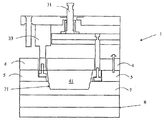
도 1은 횡단면도로 나타낸 몰드 시스템의 분해 측면도이며,
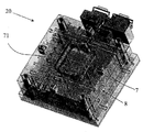
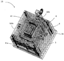
도 2a 및 도 2b는 종래 기술에 따른 몰드 시스템의 사시도이며,
도 2c는 공지된 몰드 시스템에 의해 제공되는 용기의 사시도이며,
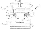
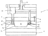
도 3a 내지 도 3d는 용기의 다양한 부분에 대한 제조 단계에서 몰드 시스템의 작동을 도시하는 종단면도이며,
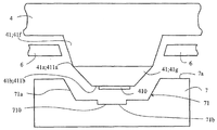
도 4는 각각 용기 몸체를 성형하는 인서트를 포함하는 성형 코어와 몰드 공동의 종단면을 나타내는 측면도이며,
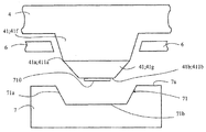
도 5는 단지 하나만이 용기 몸체를 성형하는 인서트를 포함하는 성형 코어와 몰드 공동의 종단면을 나타내는 측면도이며,
도 6은 용기의 깊이를 변경시키기 위해 자기 시스템에 의해 몰드 공동에 인서트가 부착되는 몰드 판의 횡단면을 나타내는 평면도이다.1 is an exploded side view of a mold system in a cross sectional view,
2A and 2B are perspective views of a mold system according to the prior art,
2C is a perspective view of a container provided by a known mold system,
3A-3D are longitudinal cross-sectional views illustrating the operation of the mold system at the manufacturing stage for various portions of the container,
4 is a side view showing a longitudinal section of a forming core and a mold cavity, each comprising an insert for forming a container body,
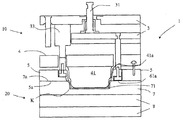
5 is a side view showing a longitudinal section of a mold core and a mold cavity comprising inserts for molding only one container body,
6 is a plan view showing a cross section of a mold plate to which an insert is attached to a mold cavity by a magnetic system to change the depth of the container.
이후에, 상기 몰드 시스템(1)이 먼저 설명되며 도 1 내지 도 3을 참조하여 몰드 시스템의 작동에 대해 설명된다. 칼라 링과 시일 링에 관하여, 도 2a 및 도 2b에 도시된 몰드 시스템은 본 발명에 사용된 것과 동일하지 않으나, 이들은 본 발명에 따른 몰드 시스템의 기본 구조를 도시하고 있다.In the following, the
도 1은 측면도 및 횡단면도로 본 본 발명에 따른 몰드 시스템의 주요 부분에 대한 분해도이다. 상기 몰드 시스템(1)은 가동식 몰드 하프(10) 또는 "후방 몰드" 및 부동식 몰드 하프(20) 또는 "전방 몰드"를 포함한다. 상기 가동식 몰드 하프(10)의 주요 부분은 방출 바아(31)를 포함하는 방출 부분(30)을 포함하며, 상기 방출 부분의 투피스(two-piece) 몸체(3)는 상기 몸체의 부분(3a,3b)들 사이에, 상기 몰드 하프(10,20)들 사이의 압착을 제공하기 위한 공압식 작동기(33)를 포함한다. 상기 가동식 몰드 하프(10)는 평판형 시일 링(5), 평판형 칼라 링(6) 및 (성형)코어(41)가 부착되는 코어 판(4)도 포함한다. 부동식 몰드 하프(20)는 몰드 공동(71)을 포함하며, 평면 판지 블랭크(blank)가 성형되고 팩키지의 일반적인 형상(바닥, 바닥으로부터 연장하는 측면 벽들의 형상, 벽의 경사, 라운딩 등)을 결정하는 몰드 판(7)을 포함한다. 본 발명에서 판지 블랭크는 판지 블랭크 또는 판지-기반 블랭크를 지칭하며, 판지는 배리어 특성을 변경시키기 위해 플라스틱 또는 금속 층으로 코팅될 수 있다. 게다가, 부동식 몰드 하프(20)는 몰드 프레임(8)을 포함하며, 몰드 프레임을 통해 캐스팅 도관이 도 2a 및 도 2b에 상세히 도시한 방식으로 테두리(rim)의 캐스팅 지점으로 이송된다.1 is an exploded view of the main part of a mold system according to the invention in side and cross sectional views. The
시일 링(5)은 성형 코어(41) 주위에 환형으로 위치된다. 시일 링(5)과 성형 코어(41)에 대해 깊이 방향으로 이동가능한 칼라 링(6)은 시일 링(5)과 성형 코어(41) 사이에 배열된다. 본 발명에서 깊이 방향은 코어 판(4)의 표면(4a)에 수직한 방향을 지칭한다. 시일 링(5)은 프레싱 단계의 말기에서 코어(41)의 몰딩 부분의 면(41a)에 일직선이 되는 시일 표면(5a)을 포함한다. 상기 몰딩 부분의 면은 형성된 용기의 테두리의 평면, 즉 몰드 판(7)의 시일 표면(7a)의 평면이 되는 동시에, 몰드 공동(71)의 상부 에지의 평면이 되는 코어(41)의 부분을 지칭한다. 도 1에 도시된 성형 코어(41)의 몰드 부분은 몰드 공동(71) 내측에 끼워 맞춰질 수 있는 코어의 부분이다. 도 1 에 도시된 성형 코어(4)의 장착 부분 및 대응하는 몰드 공동(71)은 둥근 장방형 형상의 횡단면 프로파일을 가짐으로써, 그에 따라 예를 들어 도 5a에 도시된 둥근 장방형의 횡단면을 가지는 용기를 제공할 수 있다. 몰드 공동, 성형 코어 및 용기의 횡단면 프로파일들은 몰드 시스템(1)의 깊이 방향, 즉 몰드 판(7) 및 코어 판(4)의 표면에 수직한 방향으로 본 횡단면을 지칭한다. 성형 코어의 장착 부분과 몰드 공동의 횡단면 프로파일들이 예를 들어, 원의 형태로 변경되면, 원형 횡단면을 갖는 용기가 도 2c에 도시한 바와 같이 각각 얻어진다.The
시일 링(5)의 시일 표면(5a)은 전방 몰드(20)의 몰드 공동(71)을 에워싸는 몰드 판(7)의 대응하는 시일 표면(7a)과 반대이다. 상기 코어(41)는 시일 링(5)의 시일 표면(5a)에 대해 짧은 왕복 운동을 수행할 수 있는 칼라 링(6), 및 상기 시일 링(5)의 시일 표면(5a)의 평면과 그로부터 후방으로 매우 짧은 거리만큼 이동될 수 있는 부동식 몰드 하프(20)로 선회되는 칼라 링(6)의 칼라(61)의 시일 표면(61a)에 의해 추가로 에워싸인다.The
도 2a는 공지된 몰드 시스템(1B)에 사용되는 부동식 몰드 하프(20)를 도시하며 도 2b는 대응하는 가동식 몰드 하프를 도시한다. 이러한 몰드 하프의 기능과 몰드 구조에 관해서, 이러한 몰드 시스템(1B)은 본 발명에 따른 것과 동일한 형태이며, 그 구조는 코어(41)을 에워싸는 시일 링(5) 및 칼라 링(6)의 구조와 관련하여 본 발명에 따른 몰드 시스템으로부터 대부분 벗어난 것이다. 전방에 있는 부동식 몰드 하프(20)에 위치된 것은 트레이 형상을 갖는 리세스, 즉 몰드 공동(71)을 포함하는 몰드 판(7)이다. 부동식 몰드 하프(20)의 몰드 판(7)은 몰드 프레임(8)에 부착되며, 상기 몰드 프레임을 통해서 캐스팅 도관 또는 핫 채널 및 노즐이 후술되는 캐스팅 공동의 내측으로 플라스틱을 도입하기 위해 이송된다. 가동식 몰드 하프(10)도 또한, 성형 코어(41)의 전방에서 코어 판(4)에 부착되는 동일한 것을 포함한다. 코어 판(4)은 가동식 몰드 부분(10)의 배출 부분(30)에 부착된다. 상기 코어(41)는 코어 모듈 부분의 면(41a)과 상기 코어 모듈 부분의 면과 일직선인 시일 표면(61a)으로 연장하는 평판형 칼라 링(6), 및 상기 시일 표면(5a)을 포함하며 상기 칼라 링의 외측에 있고 칼라 링으로 한정되어 있는 평판형 시일 링(5)에 의해 에워싸인다.FIG. 2A shows the floating
도 3a 및 도 3b는 본 발명에 따른 몰드 시스템(1)의 횡단면도를 도시하며, 여기서 몰드 하프는 도 1, 도 2a 및 도 2b를 참조하여 설명한 것과 동일하다. 몰드 시스템(1)은 트레이 팩키지를 프레싱하는 것에서 출발하여 테두리를 캐스트팅하는 것으로 끝나는 트레이 패키지의 성형에 사용된다. 상기 몰드 시스템(1)은 두 개의 몰드 하프(10,20)로 형성되는 압착 몰딩 및 캐스팅을 위한 몰드를 포함하며, 상기 몰드의 목적은 제 1 단계에서, 필수적으로 직선이고 균일한 판지 블랭크로부터 용기형 트레이 팩키지를 몰딩하기 위한 것이다. 캐스팅 기능은 압착 성형되는 팩키지(500)의 벽들의 에지 상에 테두리(50)를 캐스팅하기 위해 몰드 시스템(1)에 통합된다.3a and 3b show a cross-sectional view of a
칼라 링(6)의 칼라(61)의 시일 표면(61a), 즉 부동식 몰드 하프(20)로 선회되는 면(61a)이 시일 링(5)의 시일 표면(5a)과 일직선이 될 때, 공통의 시일 표면이 시일 링의 시일 표면 및 칼라(61)의 면 또는 시일 표면(61)에 의해 형성된다. 몰드가 도 3b 내지 도 3d에 따라 폐쇄될 때(몰드 하프(10,20)가 합체될 때), 부동식 몰드 하프(20)의 몰드 판(7)의 시일 표면(7a) 및 가동식 몰드 하프(10)의 공통의 시일 표면(5a,61a)은 서로 직면하게 되어, 성형될 판지 블랭크(K)가 상기 표면들 사이에 유지되게 된다. 배출 부분(30)의 몸체(30)의 부분(3a,3b)들 사이의 공압식 작동기(33)는 칼라 링(6)에 연결되며 칼라 링(6)을 통해 시일 링(5)과 그에 따라 가동식 몰드 하프(10)의 공통의 시일 표면(5a,61a)을 프레싱함으로써 몰드 하프(10,20) 사이, 즉 부동식 몰드 하프의 시일 표면(7a)과 공통의 시일 표면(5a,61a) 사이에 유지력을 제공한다. 상기 시일 표면들 사이의 판지 블랭크(K) 이외에도 상기 시일 표면(7a) 상에 가해지는 압착력 또는 유지력의 대부분은 시일 링(5)의 시일 표면(5a)에 의해 발생되나, 칼라 링의 칼라(61)의 시일 표면(61a)도 판지 블랭크(K) 상에 유지력을 가한다. 상기 유지력은 압력 매체에 의해 작용하는 압축 공기 실린더와 같은 작동기(33)에 의해 조절될 수 있다. 칼라 링(6)은 시일 링(5)과 코어(41) 사이의 배출 부분(3) 내측에 위치된다.When the
코어(41)를 포함하는 코어 판(4)과 배출 부분(30)의 두 부분으로 이루어지는 몸체(3)가 부동식 몰드 하프(20)에 대해 깊이 방향으로 배출 바아(31)에 의해 이동될 수 있으며, 여기서 깊이 방향은 전술한 것과 동일하다. 따라서 가동식 몰드 하프(10)는 (도 3a에 도시된)전방 위치와 (도 3b 내지 도 3d에 도시된)후방 위치 사이에서 이동한다.A
압축 단계에서, 몰드 시스템 내의 가동식 몰드 하프(10)는 고정식 몰드 하프(20)의 몰드 판(7)의 몰드 공동(71)의 내측으로 판지 블랭크(K)를 프레싱한다. 이를 위해, 가동식 몰드 하프는 코어 판(4) 상에 위치된 성형 코어(41)를 포함하며, 그의 성형 부분이 코어의 면(41a)까지 전술한 몰드 공동(71)의 내측에 끼워 맞춰져서 판지 블랭크가 코어(41)와 상기 공동(41) 사이에서 프레싱됨으로써 트레이 형상이 얻어진다. 가동식 몰드 하프(10)는 본 발명에서 상세히 설명하지 않는 장치에 의해 몰드를 개폐하도록 부동식 몰드에 대해 이동되도록 배열된다. In the compression step, the
도 3a는 몰드를 폐쇄하기 이전의 몰드 시스템(1)을 도시한다. 판지 블랭크(K)는 로봇에 의해 부동식 몰드 하프(20)의 몰드 판(7) 상의 작은 홀더(도시 않음)로 이송된다. 이후에, 상기 몰드는 폐쇄, 즉 상기 코어(41)는 몰드 공동(71)의 내측에서 안정되며 이들 사이에 남아 있는 판지 블랭크(K)가 트레이 형상의 용기로 프레싱된다.3a shows the
상기 공동(71) 내측에 설정한 후에 상기 코어(41)가 블랭크를 성형하기 시작하는 단계가 도 3b에 도시되어 있다. 시일 표면, 즉 시일 링의 시일 표면(5a) 및 칼라 링의 시일 표면(61a)은 작동기(33)의 힘에 의해 판지 블랭크(K) 상에 위치되며 상기 압축 단계에서 부동식 몰드 하프의 몰드 판(7)의 시일 표면(7a)과 상기 시일 표면(5a,61a) 사이의 에지에 블랭크(K)를 유지한다.The step in which the
도 3c는 몰드가 완전히 폐쇄되어 있고, 몰드 하프(10,20)가 서로에 대해 압박되어 있으며 상기 몰드 하프 사이에 있는 판지 블랭크(K)가 트레이로 프레싱되어서, 트레이의 측벽의 상부 에지가 칼라 링(6)의 시일 표면(61a)과 일직선을 이루거나 시일 표면의 약간 전방에 있다. 블랭크의 에지 상의 최후의 유지력은 칼라 링(6)의 칼라(61)의 면(61a)에 의한 것이며, 상기 칼라의 면에 부동식 몰드 하프의 공동(71)을 에워싸는 몰드 판의 시일 표면(7a)이 대면해 있다.3C shows that the molds are fully closed, mold halves 10 and 20 are pressed against each other and the cardboard blank K between the mold halves is pressed into the tray so that the upper edge of the sidewall of the tray is collared. It is in line with the
도 3d는 몰드가 여전히 폐쇄되어 있으나, 부동식 몰드 하프(20)의 시일 표면(71a)으로부터 후방으로, 즉 가동식 몰드 하프(10)의 배출 부분(3)의 방향으로 짧은 거리만큼 이동된 상태를 도시한다. 상기 이동은 예를 들어 배출 모터에 의해 배출 바아(31)를 당김으로써 정밀한 이동을 수행하는 작동기에 의해 제공된다. 그 후 작은 캐스팅 공동(34)이 공동(71)을 에워싸는 시일 표면(7a), 시일 링(5)의 시일 표면(5a), 칼라 링(6)의 칼라(61)의 면(61a) 및 코어(41)의 면(41a) 사이에 남아 있으며, 상기 캐스팅 공동은 트레이의 외측 에지와 접촉하며 트레이를 환형으로 에워싼다. 용융 플라스틱 재료가 이러한 캐스팅 공동(43)으로 이송되면, 상기 플라스틱 재료는 트레이의 측벽으로부터 외측으로 연장하는 플랜지형 테두리를 형성한다. 이러한 형상으로 인해, 칼라 링(6)은 캐스팅 공동(43)의 밀착(tightness)을 확보하기 위해 성형 코어(41)에 대해 밀착된다. 캐스팅 재료의 사출 채널이 부동식 몰드 하프(20)의 몰드 프레임(8)을 통해 배열되며 캐스팅될 플라스틱이 이를 통해 캐스팅 공동(43)으로 이동한다. 사출 채널은 또한, 성형되는 용기의 구조에 따라서 다른 방식으로 사출 채널 내에 도달하도록 배열될 수 있다.FIG. 3D shows the mold still closed but moved back a short distance from the
용융 플라스틱 재료가 캐스팅 공동(43) 내에서 고화된 이후에, 몰드는 다시 개방 위치로 개방될 수 있다. 그 후 배출 부분(3)은 여전히 후방 위치에 있다. 배출 부분(3)이 배출 로드(31)에 의해 전방 위치로 밀리면, 배출 부분은 마무리된 용기를 가동식 몰드 하프(10)로부터 제거하는 동시에, 칼라 링(6)이 전방 위치로 다시 이동될 수 있다. 즉, 도 3a에 도시된 위치를 다시 취하게 된다. 그 후 전방 몰드(20)의 몰드 판(7)의 시일 표면(7a)이 마무리된 용기가 몰드로부터 제거될 때 배출 바아가 밀리게 되는 배출 표면으로서 작동한다. 이 후에, 로봇은 마무리된 용기를 꺼내서 새로운 블랭크(K)와 교체되며, 그 후에 그러한 작동 상태가 전술한 바와 같이 반복된다.After the molten plastic material has solidified in the
몰드 공동으로서 사용함으로써, 그리고 둥근 바닥을 갖는 용기에 적합한 공동 및 해당 몰드 공동의 형상을 적합하게 하도록 성형 코어의 몰드 부분의 형상을 채용함으로써 전술한 몰드 시스템은 둥근 바닥을 포함하며 상기 바닥(57)에 연결되는 상방향으로 연장하는 벽(59)을 포함하며 판지 블랭크로부터 압착 몰딩된 몸체(58)를 포함하는 도 2c에 도시된 용기(500)를 제조하는데 사용될 수 있다. 외측으로 연장하는 플랜지형 플라스틱 테두리(50)가 벽(59)의 상부 에지에 캐스팅된다.By using as a mold cavity and employing the shape of the mold portion of the forming core to fit a cavity suitable for a container having a rounded bottom and the shape of the mold cavity, the above-described mold system comprises a rounded bottom and the bottom 57 It can be used to manufacture the
판지 블랭크로부터 프레싱되는 몸체, 즉 바닥(57) 또는 벽에 양면 장식용 또는 기능성 엠보싱 또는 상감세공(inlaid)함으로써 도 2c에 도시된 용기를 성형할 때, 이러한 성형은 본 발명에 따른 몰드 시스템에 사용되는 성형 코어 및 도 4에 따른 대응하는 성형 공동(71)을 변경함으로써 수행될 수 있다. 도 4는 코어 판(4)에 부착되는 성형 코어(41)를 개략적으로 도시하며, 상기 성형 코어는 두 개의 부분, 즉 그 길이가 변경되지 않고 유지되고 상기 성형 코어의 코어 판(4)에 부착되는 베이스 부분(41f), 및 그 길이가 변경되고 상기 베이스 부분에 부착되는 상기 코어의 부착 부분(41g)으로 이루어진다. 돌기(410)는 부착 부분(41g)의 외측 에지(411b)에 연결되는 동시에, 코어의 외측 에지(41b)로서 작동하며, 상기 돌기는 인서트로서 사용되며 상기 코어의 외측 에지의 평면으로부터 하방향으로, 즉 몰드 판(7)의 시일 표면(7a)의 평면의 방향에 수직하게 지향된다. 도 4는 또한, 코어 판(4) 아래에 위치되고 성형 코어(41)를 에워싸는 칼라 링(6)을 도시한다. 상기 코어(41)의 부착 부분(41g)은 소정의 지점에서 코어의 베이스 부분(41f)에 연결될 수 있으나, 일반적으로 부착 부분(41f)은 도 3a 내지 도 3c에 도시된 방식으로 성형되도록 판지 블랭크(k)가 프레싱될 때 코어의 성형 부분, 즉 몰드 공동(71) 내측에 끼워 맞춰지는 부분을 구성하도록 코어(41)를 형성하는 것이 바람직하다. 그 후 부착 면(411a)은 코어의 면(41a)으로서 기능을 하며 몰드 판(7)의 시일 표면(7a)과 일직선이 되거나 코어(41)가 몰드 공동(71) 내측으로 프레싱될 때 가동식 몰드 하프(10)의 방향으로 시일 표면의 조금 위에 있게 된다. 상기 코어(41)의 부착 부분(41g)은 스크류 체결과 같은 적합한 체결 방식에 의해 코어의 베이스 부분(41f)에 연결된다. 코어의 부착 부분(41g)과 베이스 부분(41f) 사이의 조인트가 형성된 용기의 플라스틱 테두리에 복제되지 않기 때문에, 코어의 베이스 부분(41f)과 코어의 부착 부분(41g)의 상호 체결도 본 기술 분야에 공지된 다른 체결 방법에 의해 실시될 수 있다. 도 4에 따른 몰드 공동과 성형 코어의 쌍에 있어서, 상기 코어의 부착 부분(41g)의 돌기(410)에 대응하는 리세스(710)가 몰드 판(7)의 몰드 공동(71)의 베이스(71b)에 형성된다. 이 경우에, 몰드 공동(71)의 인서트는 실제로, 도 5에 따른 몰드 시스템이 형성될 때, 몰드 공동의 평탄한 베이스(71b)로부터 제거되고 바닥(71b)에 재연결될 수 있는 인서트이며, 여기서 상기 몰드 공동(71)의 바닥(71b)은 평탄하고 그에 따라 판지 블랭크로부터 형성되는 용기 부분의 몸체(58)의 한쪽 면에 형상이 생성된다. 도 4에 따른 성형 코어와 몰드 공동의 쌍이 도 1 내지 도 3에 의해 이전에 설명한 방식으로 용기(500)를 제조하는데 사용될 때, 코어 부착 부분(41g)의 돌기(410)가 압착 단계, 즉 도 3b 및 도 3c에 도시한 작업 단계에서 몰드 공동(71)의 바닥에 프레싱된다. 그 경우에, 상기 돌기(410)는 리세스(710)쪽으로 상기 성형 코어(41)와 몰드 공동(71) 사이에 놓인 판지 블랭크를 밀며, 상기 리세스는 몰드 공동(71)의 바닥(71b)에 있으며 상기 돌기보다 조금 큰 바닥 면적과 돌기와 동일한 형상을 가진다. 따라서, 용기의 내측 리세스가 제조되는 용기(500)의 바닥(57)의 내측 표면에 복제되며, 상기 바닥 외측면의 나머지로부터 하방향으로 연장하는 대응하는 돌출부가 상기 바닥의 외측 표면에 복제된다.When shaping the container shown in FIG. 2C by double-sided decorative or functional embossing or inlaid on a body, ie bottom 57 or wall, pressed from a cardboard blank, such molding is used in a mold system according to the invention. This can be done by changing the forming core and the corresponding forming
도 5에 도시된 성형 코어(41) 및 그와 대향하는 몰드 공동(71)는 도 4에 따른 성형 코어 및 그와 대향하는 몰드 공동은 단지 몰드 공동(71b)의 바닥이 평탄하는 점에서만 상이하다. 상기 베이스에는 베이스를 깊게하는 인서트(710)가 어느 쪽에도 제공되지 않거나, 몰드 공동의 베이스의 분리가능한 인서트(710)가 베이스에 재부착된다. 도 5에 따른 성형 코어와 몰드 공동의 쌍이 용기(500)의 제조에 사용될 때, 코어 부착 부분(41g)의 돌기(410)는 압착 단계에서 몰드 공동(71)의 바닥(71b)으로 프레싱되며 돌기(410)는 성형 코어(41)와 몰드 공동(71) 사이에 있는 판지 블랭크(k)를 도 3a 및 도 3b에 도시한 방식으로 몰드 공동(71)의 평탄한 바닥(71b)쪽으로 민다. 리세스는 제조되는 용기(500)의 바닥의 내측 표면에만 복제되며 바닥(71b)의 외측 표면은 평탄한 상태로 남아 있다.The forming
도 6은 판지 블랭크로부터 프레싱되는 용기(500)의 깊이, 즉 몰드 공동(71)의 베이스(71b) 상에 몰드 공동(71)의 깊이를 감소시키는 분리가능한 인서트(720)를 배열함으로써 벽의 상부 에지로부터 용기 바닥까지의 거리를 변경한 본 발명의 실시예를 도시한다.6 shows the top of the wall by arranging a
도 6은 분리가능한 인서트(720)가 몰드 공동(71)의 베이스의 상부에 부착되는 몰드 판(7)을 도시한다. 상기 몰드 공동의 상부 에지, 즉 몰드 판(7)의 상부 표면(시일 표면)은 베이스(71b)에 의해 한정된 평면으로부터의 높이(H)에 위치되는데, 이는 또한 상기 몰드 공동의 가장 큰 깊이이다. 인서트(720)의 바닥은 베이스(71B) 상에 지지된다. 새로운 인서트(스페이서)가 높이가 h가 되는, 몰드 공동의 베이스(71b)에 추가되면, 상기 인서트(720)의 상부 표면(71b)은 몰드 공동의 새로운 바닥(71b)으로서 작용함으로써, 상기 깊이(H)로부터 새로운 깊이(H-h)로 몰드 공동의 깊이를 감소시킨다. 도 6의 인서트의 형상은 베이스에 의해 한정된 평면으로부터 몰드 공동의 높이(h)까지 몰드 공동(71)의 하부에 있는 벽(71a)과 베이스(71b)에 의해 한정된 공간을 완전히 채우는 몰드 공동의 베이스 상에 밀착되게 끼워질 수 있게 한다. 상기 인서트의 상부 표면(71b)은 연속적이고 평탄함으로써, 몰드 공동의 새로운 바닥으로서 사용될 수 있다. 상기 인서트의 연속적인 상부 표면도 의도된 용기의 바닥(57)의 형상과 관련하여 적합하다면 하방향으로 오목하거나 상방향으로 볼록한 형상을 가질 수 있다.6 shows a
몰드 공동(71)의 깊이가 인서트(720)만큼 감소되어서 몰드 공동(71)의 새로운 깊이가 H-h가 되면, 코어의 베이스 부분(41,41f)의 단부에 연결되고 길이를 변경하지 않은 코어 부착 부분(41g)의 길이는 몰드 공동(71)의 바닥 상에 놓이는 인서트(720)의 높이(h)만큼 감소된다. 그 후, 도 3b에 따른 판지의 압착 단계에서 몰드 공동의 내측으로 관통하는 코어의 성형 부분의 길이는 H-h가 된다.When the depth of the
그 후, 상기 코어는 베이스 부분(41,41f) 및 상기 베이스 부분의 상부에 연결될 수 있는 부착 부분(41g)으로 이루어진다. 이러한 방식으로, 코어의 성형 부분의 길이는 길이를 변경하지 않은 코어 베이스 부분(41)의 길이 및 길이를 변경하고 코어의 베이스 부분의 상부에 연결되는 상기 코어 부착 부분(41g)의 길이를 서로에 대해 대응하게 변경시킴으로써 변경될 수 있다. 이러한 방식으로, 다른 것들 중에서도 트레이 바닥의 표면적은 트레이의 깊이의 변경과 무관하게 전과 같이 유지될 수 있다.The core then consists of a
몰드 공동(71)의 바닥(71b)에 부착되는 도 6에 도시된 인서트(720)는 영구 자석(M)을 포함하는 자석 시스템(S)에 의해 몰드 공동의 바닥(57)에 분리가능하게 연결된다. 스크류 체결과 같은 다른 분리가능한 체결 방법도 사용될 수 있다. 상기 자석 시스템(S)에서, 영구 자석(M)을 에워싸는 절연체(E) 및 자화 가능한 인서트(720)가 몰드 공동(71) 내에 형성된다. 이와는 달리, 상기 자석 시스템(S)은 영구 자석을 에워싸는 자화불가능한 절연체에 의해 절연될 수 있음으로써, 상기 인서트(720)는 자석 시스템(S) 쪽으로 지향된 것과는 달리 표면이 자화 불가능한 코팅으로 코팅될 수 있다. 이러한 해결책은 자석으로 선회되는 것과는 다른 쪽 표면이 자화 불가능한 코팅으로 코팅될 때 자화 가능한 인서트의 자장이 몰드의 작동에 의해 방해받지 않는 장점을 제공한다.The
상기 자석 시스템(S)은 본 예에서 두 개의 철 시이트(Me1)인 비자성 금속(M2)의 양쪽에 있는 자화가능한 금속, 및 알루미늄과 같은 자화불가능한 금속 시이트(Me1) 내의 개구에 끼워 맞춰지며 둥근 횡단면 프로파일을 갖는 영구 자석 로드(M)로 이루어진다. 상기 자석(M)이 개구 내부로 선회되면, 그 변화에 따라 자장이 생성된다. 자석이 선회되어 자장이 철 시이트(Me1)의 방향으로 이동되면, 상기 철 시이트는 자석의 작용을 방해하여 자장이 인서트(720)를 통해 이동하지 못한다. 그 후 상기 자석은 오프 포지션(off position) 상태로 된다. 영구 자석 로드(M)가 반대 방향으로 선회되면, 자장은 비자성 금속(Me2)을 통해 철 시이트(Me1) 쪽으로 이동함으로써, 철 시이트(Me1)는 자장을 강화하며 자석은 온 포지션(on position) 상태가 된다. 자장이 오프 포지션 상태가 되도록 비자성 금속(Me2) 내에 있는 개구 내부의 영구 자석 로드를 선회시킴으로써, 상기 인서트(720)가 서로 신속하게 대체될 수 있다. 자석을 다시 온 포지션 상태로 선회시킴으로써, 인서트(720)는 몰드 공동(71)의 바닥(71b)에 부착될 수 있다.The magnet system S is in this example fitted to the opening in the magnetizable metal sheet Me1, such as aluminum, and the magnetizable metal on both sides of the non-magnetic metal M2, which are two iron sheets Me1, and are rounded. It consists of a permanent magnet rod M with a cross section profile. When the magnet M is pivoted into the opening, a magnetic field is generated according to the change. When the magnet is pivoted and the magnetic field is moved in the direction of the iron sheet Me1, the iron sheet prevents the magnet from working so that the magnetic field cannot move through the
본 발명의 단지 몇몇 실시예만이 위에서 설명되었지만, 특허청구범위에 청구된 본 발명의 범주 내에서 다양한 다른 방식으로 본 발명이 실시될 수 있다는 것은 본 기술 분야의 당업자들에게 분명하다.Although only a few embodiments of the invention have been described above, it will be apparent to those skilled in the art that the invention may be practiced in various other ways within the scope of the invention as claimed in the claims.
따라서, 영구 자석은 또한, 인서트가 몰드 공동의 베이스 상에 놓인다면, 몰드 공동의 절연체 없이도 사용될 수 있으며, 그에 따라 영구 자석은 또한 상당히 작아질 수 있다.Thus, the permanent magnet can also be used without the insulator of the mold cavity if the insert lies on the base of the mold cavity, so that the permanent magnet can also be quite small.
이와 같이, 도 4 및 도 5에 따른 본 발명의 실시예들에서 코어 판(4) 상에 있는 전체 코어가 대체될 수 있다. 그 경우에, 도 4 및 도 5에서 인서트로서 사용된 코어(41)의 돌기(410)는 실제 성형 코어(41)의 외측 에지(41b)에 부착된다. 유사하게, 도 4 및 도 5에 도시된 본 발명의 실시예에서도, 코어(41)의 부착 부분(41g)에는 돌기(410)가 제공되며 몰드 공동(71)의 바닥(71b)에는 상기 돌기(410)에 대응하는 리세스(710)가 제공되며, 상기 몰드 공동(71)의 바닥(71b)에 상방향으로 연장하는 돌기를 제공하고 상기 몰드 코어(41)의 부착 부분(41g)의 외측 에지(411b)에 대응하는 리세스를 제공함으로써 동일한 결과가 얻어진다. 도 6의 코어 판 내에 놓이는 코어(41)의 길이는 주형 공동의 깊이 변화에 따라 채택되어서, 판지 블랭크의 압착 단계에서 몰드 공동의 내측으로 관통하는 코어 부분의 길이가 인서트가 제공된 몰드 공동의 깊이(H-h)와 동일하다.As such, in the embodiments of the invention according to FIGS. 4 and 5, the entire core on the
용기(500)의 벽(59)에도 다양한 한 면 또는 양면 상의 기능성 또는 장식용 엠보싱 또는 상감세공 형상이 제공될 수 있다. 그 경우에, 돌출부와 리세스가 코어(41) 또는 코어의 부착 부분(41g)의 벽 및/또는 상기 코어의 외측 단부 대신에 몰드 공동의 벽(71a) 및 몰드 공동의 바닥(71b)에 놓일 수 있다.The walls 59 of the
Claims (10)
서로 반대로 반대편에 위치되는 가동식 몰드 하프(10) 및 부동식 몰드 하프(20)를 포함하며; 상기 몰드 시스템은 판지 블랭크로부터 프레싱되는 바닥(57)과, 상기 바닥에 연결되는 벽(59), 및 플라스틱으로 적어도 부분적으로 캐스팅되고 상기 벽의 상부 에지에 연결되며 상기 벽들을 에워싸는 테두리(50)를 포함하는 용기(500)의 제조를 가능하게 하며; 상기 부동식 몰드 하프(20)와 관련하여 이동가능한 상기 가동식 몰드 하프(10)는 적어도, 코어(41)가 제공된 코어 판(4)과, 상기 코어(41)와 관련하여 이동가능하고 셧-오프(shutt-off) 표면(5a)을 포함하며 상기 코어(41)를 둘러싸는 평판형 시일 링(5), 및 상기 코어(41)와 상기 시일 링(5) 사이에 위치됨으로써 상기 용기 상에 테두리(50)가 형성될 수 있게 하며 상기 시일 링(5)과 상기 코어(41)와 관련하여 이동될 수 있는 칼라 링(6)을 포함하며; 상기 부동식 몰드 하프(40)는 적어도, 몰드 공동(71) 및 시일 표면(7a)이 제공된 몰드 판(7)을 포함하는; 판지-기반 용기 제조용 몰드 시스템(1)에 있어서,
인서트(720)가 상기 몰드 공동(71)의 베이스(71b) 상에 지지되고 상기 베이스에 분리가능하게 부착될 수 있으며, 상기 인서트는 높이(h)만큼 상기 몰드 공동의 깊이(H)를 감소시켜서, 상기 인서트(720)의 연속적인 표면(71b')이 상기 몰드 공동의 새로운 바닥(71b')으로서 작용하며 상기 판지 블랭크의 압착 단계에서 상기 몰드 공동의 내측으로 관통하는 상기 코어(41) 부분의 길이(H)가 상기 코어 판 상의 코어(41)를 더 짧은 코어로 대체하거나, 길이가 변경되지 않는 상기 코어(41)의 베이스 부분(41F)에 길이가 변경될 수 있는 부착 부분(41f)을 분리가능하게 부착함으로써 상기 인서트의 높이(h)만큼 각각 감소될 수 있으며, 서로 대응하는 상기 코어 또는 상기 코어의 부착 부분 및 상기 몰드 공동의 베이스의 인서트(720)가 제조되는 판지 블랭크의 깊이, 즉 상기 용기 벽(59)의 상부 에지로부터 상기 판지 블랭크로부터 프레싱되는 상기 용기 바닥(57)까지의 거리를 변경하는데 사용될 수 있는 것을 특징으로 하는,
판지-기반 용기 제조용 몰드 시스템.
As mold system 1 for making cardboard-based containers;
A movable mold half 10 and a floating mold half 20 positioned opposite each other; The mold system includes a bottom 57 pressed from a cardboard blank, a wall 59 connected to the floor, and an edge 50 at least partially cast from plastic and connected to the top edge of the wall and surrounding the walls. To enable the manufacture of a container 500 comprising; The movable mold half 10 movable in relation to the floating mold half 20 is at least a core plate 4 provided with a core 41, and movable and shut-off in relation to the core 41. a planar seal ring 5 comprising a shutt-off surface 5a and surrounding the core 41 and between the core 41 and the seal ring 5 so as to provide an edge on the container. A collar ring 6 which allows 50 to be formed and which can be moved in relation to the seal ring 5 and the core 41; The floating mold half 40 comprises at least a mold plate 7 provided with a mold cavity 71 and a seal surface 7a; In a mold system 1 for producing cardboard-based containers,
An insert 720 can be supported on the base 71b of the mold cavity 71 and detachably attached to the base, the insert reducing the depth H of the mold cavity by a height h. The continuous surface 71b 'of the insert 720 acts as a new bottom 71b' of the mold cavity and of the portion of the core 41 that penetrates into the mold cavity in the pressing step of the cardboard blank. The length H replaces the core 41 on the core plate with a shorter core, or the attachment portion 41f whose length can be changed to the base portion 41F of the core 41 whose length does not change. By detachably attaching each can be reduced by the height h of the insert, the depth of the cardboard blank from which the insert 720 of the core or the attachment portion of the core and the base of the mold cavity corresponding to each other is produced, ie The container From the top edge (59), characterized in that that may be used to change the distance to the container bottom 57 is pressed from the cardboard blank,
Mold system for making cardboard-based containers.
상기 인서트(720)는 상기 몰드 공동(71)의 베이스(71b)에 분리가능하게 부착되며, 상기 인서트의 높이는 h이며 상기 몰드 공동의 하부분에 꼭 맞는 형상을 가지며, 상기 몰드 공동은 상기 몰드 공동의 베이스(71b)와 상기 몰드 공동의 베이스에 연결되는 벽(71a)에 의해 제한되며, 상기 인서트(720)는 상기 용기(500)의 테두리(50)와 바닥(57) 사이의 거리를 감소시킬 수 있으며, 상기 용기는 판지 블랭크로부터 프레싱되는 바닥(57) 및 상기 바닥에 연결되는 벽(59)을 포함하며, 상기 테두리(50)는 플라스틱으로 적어도 부분적으로 캐스팅되고 상기 벽의 상부 에지에 연결되며 상기 벽들을 에워싸는 것을 특징으로 하는,
판지-기반 용기 제조용 몰드 시스템.
The method of claim 1,
The insert 720 is detachably attached to the base 71b of the mold cavity 71, the height of the insert is h and has a shape that fits well under the mold cavity, the mold cavity being the mold cavity. Constrained by a wall 71a connected to the base 71b of the mold cavity and the base of the mold cavity, the insert 720 may reduce the distance between the rim 50 and the bottom 57 of the container 500. Wherein the container comprises a bottom 57 pressed from a cardboard blank and a wall 59 connected to the bottom, wherein the rim 50 is at least partially cast from plastic and connected to the top edge of the wall Characterized by surrounding the walls,
Mold system for making cardboard-based containers.
상기 인서트(720)는 상기 몰드 공동(71)의 바닥에 자기적으로 부착될 수 있는 것을 특징으로 하는,
판지-기반 용기 제조용 몰드 시스템.
The method according to claim 1 or 2,
The insert 720 can be magnetically attached to the bottom of the mold cavity 71,
Mold system for making cardboard-based containers.
상기 인서트(720)는 영구 자석(M)에 의해 상기 몰드 공동(71)의 베이스(71b)에 부착될 수 있으며, 상기 영구 자석의 자장은 스위치 온 및 스위치 오프될 수 있는 것을 특징으로 하는,
판지-기반 용기 제조용 몰드 시스템.
The method of claim 3, wherein
The insert 720 may be attached to the base 71b of the mold cavity 71 by a permanent magnet M, and the magnetic field of the permanent magnet may be switched on and off.
Mold system for making cardboard-based containers.
상기 인서트(720)는 영구 자석(M) 및 상기 영구 자석(M)을 둘러싸는 절연체(E)를 포함하는 자석 시스템(S)에 의해 상기 몰드 공동(71)의 베이스(71B)에 부착될 수 있으며, 자화 가능한 상기 인서트(720)는 상기 자석 시스템(S) 내의 상기 몰드 공동(71) 내에 형성되는 것을 특징으로 하는,
판지-기반 용기 제조용 몰드 시스템.
The method according to claim 3 or 4,
The insert 720 may be attached to the base 71B of the mold cavity 71 by a magnet system S comprising a permanent magnet M and an insulator E surrounding the permanent magnet M. FIG. And the magnetizable insert 720 is formed in the mold cavity 71 in the magnet system S,
Mold system for making cardboard-based containers.
상기 자석 시스템(S)은 자화 불가능 재료(Me2)의 양쪽에 있는 자화 가능한 재료(Me1), 및 상기 자화 불가능 재료(Me2) 내의 개구 내측에 끼워 맞춰지는 영구 자석 로드(M)로 이루어지는 것을 특징으로 하는,
판지-기반 용기 제조용 몰드 시스템.
The method of claim 5, wherein
The magnet system S is characterized in that it consists of a magnetizable material Me1 on both sides of the non-magnetizable material Me2 and a permanent magnet rod M fitted inside the opening in the non-magnetic material Me2. doing,
Mold system for making cardboard-based containers.
상기 코어(41)는 길이가 변경되지 않는 베이스 부분(41,41f), 및 상기 베이스 부분(41,41f)의 상부에 연결될 수 있는 상기 코어의 부착 부분(41,41g)으로 이루어지며, 상기 코어의 성형 부분의 길이는 상기 코어의 베이스 부분(41f)의 상부에 추가되는 상기 코어 부착 부분(41g)의 길이를 변경함으로써 변경될 수 있는 것을 특징으로 하는,
판지-기반 용기 제조용 몰드 시스템.
The method according to any one of claims 2 to 4,
The core 41 is composed of a base portion 41, 41f of which length is not changed, and an attachment portion 41, 41g of the core which can be connected to the upper portion of the base portion 41, 41f, and the core Characterized in that the length of the molded part of can be changed by changing the length of the core attachment part 41g added to the top of the base part 41f of the core,
Mold system for making cardboard-based containers.
상기 인서트(720)는 상기 몰드 공동(71)의 바닥에 부착될 수 있으며, 상기 인서트는 상기 판지 블랭크의 깊이, 즉 상기 용기 벽(59)의 상부 에지로부터 상기 판지 블랭크로부터 프레싱되는 상기 용기 바닥(57)까지의 거리를 감소 또는 증가시키는데 사용됨으로써, 상기 용기 바닥의 면적은 변경되지 않고 유지되는 것을 특징으로 하는,
판지-기반 용기 제조용 몰드 시스템.
The method according to any one of claims 1 to 7,
The insert 720 can be attached to the bottom of the mold cavity 71, the insert being pressed from the cardboard blank from the depth of the cardboard blank, ie from the top edge of the container wall 59. Used to decrease or increase the distance to 57), so that the area of the bottom of the container remains unchanged,
Mold system for making cardboard-based containers.
판지 블랭크(K)가 성형 코어(41)와 몰드 공동(71) 사이에서 프레싱됨으로써, 용기 바닥(57) 및 상기 용기 바닥을 에워싸는 벽(59)을 제공하며, 그 후에 상기 벽을 에워싸며 적어도 부분적으로 플라스틱으로 이루어진 플랜지형 테두리(50)가 상기 벽의 상부 에지 상에 캐스팅에 의해 형성되며, 상기 몰드 공동(71)의 바닥 및/또는 상기 코어(41)에 부착되는 인서트(720) 및 상기 코어의 베이스 부분(41f)에 연결되는 부착 부분(41g)이 상기 용기 벽(59)의 상부 에지로부터 상기 판지 블랭크로부터 프레싱되는 용기 바닥(57)까지의 거리를 변경시키는데 사용되는 것을 특징으로 하는,
판지-기반 몸체(58)를 가지는 용기를 제조하는 방법.
A method of manufacturing a container 500 having a cardboard-based body 58 by a mold system according to claim 1,
The cardboard blank K is pressed between the forming core 41 and the mold cavity 71, thereby providing a container bottom 57 and a wall 59 that encloses the container bottom, which then encloses the wall and at least partially. A flanged rim 50 made of plastic is formed by casting on the upper edge of the wall and is attached to the bottom of the mold cavity 71 and / or to the core 41 and the insert 720. The attachment portion 41g connected to the base portion 41f of the is used to change the distance from the upper edge of the container wall 59 to the container bottom 57 pressed from the cardboard blank,
A method of making a container having a cardboard-based body (58).
상기 판지 블랭크(K)는 적어도 상기 판지 블랭크(K)가 몰드 공동(71) 내측으로 미끄럼될 때까지 상기 시일 링의 시일 표면(5a)과 상기 칼라 링의 시일 표면(61a) 그리고 상기 칼라 링과 반대쪽의 몰드 판의 시일 표면(7a) 사이에 유지되며, 이후에 상기 용기 벽을 에워싸고 적어도 부분적으로 플라스틱으로 이루어지는 플랜지형 테두리(50)를 형성할 때까지 캐스팅 공동이 상기 몰드 시스템 내에 제공되지 않는 것을 특징으로 하는,
판지-기반 몸체(58)를 가지는 용기를 제조하는 방법.The method of claim 9,
The cardboard blank K is at least a seal surface 5a of the seal ring and a seal surface 61a of the collar ring and the collar ring until the cardboard blank K is slid into the mold cavity 71. The casting cavity is not provided in the mold system until it is held between the seal surfaces 7a of the opposing mold plate and subsequently forms a flanged rim 50 which encloses the container wall and is at least partly made of plastic. Characterized in that,
A method of making a container having a cardboard-based body (58).
Applications Claiming Priority (3)
| Application Number | Priority Date | Filing Date | Title |
|---|---|---|---|
| FI20080463A FI122782B (en) | 2008-08-12 | 2008-08-12 | A mold system and method for making a board-based container |
| FI20080463 | 2008-08-12 | ||
| PCT/FI2009/050657 WO2010018306A1 (en) | 2008-08-12 | 2009-08-12 | Mould system for changing the depth of a cardboard-based container |
Publications (1)
| Publication Number | Publication Date |
|---|---|
| KR20110044940A true KR20110044940A (en) | 2011-05-03 |
Family
ID=49753716
Family Applications (1)
| Application Number | Title | Priority Date | Filing Date |
|---|---|---|---|
| KR1020107013407A KR20110044940A (en) | 2008-08-12 | 2009-08-12 | Mold system for changing the depth of the cardboard-based container |
Country Status (11)
| Country | Link |
|---|---|
| US (1) | US8623260B2 (en) |
| EP (1) | EP2310193A1 (en) |
| JP (1) | JP5409789B2 (en) |
| KR (1) | KR20110044940A (en) |
| CN (1) | CN101883676B (en) |
| AU (1) | AU2009281037A1 (en) |
| BR (1) | BRPI0905787A2 (en) |
| CA (1) | CA2705377A1 (en) |
| MX (1) | MX2010005942A (en) |
| RU (1) | RU2497678C2 (en) |
| WO (1) | WO2010018306A1 (en) |
Families Citing this family (9)
| Publication number | Priority date | Publication date | Assignee | Title |
|---|---|---|---|---|
| FR2943576B1 (en) * | 2009-03-30 | 2011-03-18 | Saint Gobain | METHOD OF MOLDING A PIECE OF PLASTIC MATERIAL WITH A REPLACED METALLIC REPORTED PIECE BY MAGNETING, DEVICE FOR MOLDING AND USE OF A MAGNET FOR FASTENING SAID PIECE |
| JP5655406B2 (en) * | 2010-07-20 | 2015-01-21 | セントラル硝子株式会社 | Mold for molding and method for producing glass with decorative molding using the mold |
| US20140186479A1 (en) * | 2013-01-03 | 2014-07-03 | Michael Ayotte | Interchangeable molding designs |
| SE539446C2 (en) * | 2013-11-04 | 2017-09-26 | Stora Enso Oyj | Method and apparatus for deep drawing a tray from fiber-based sheet material |
| CN106458371B (en) | 2014-05-08 | 2019-10-11 | 艾福德柏格公司 | Groceries transport packaging system |
| US11453517B2 (en) | 2014-05-08 | 2022-09-27 | Ifoodbag Ab | Grocery transport packaging system |
| SE540678C2 (en) | 2014-10-17 | 2018-10-09 | Stora Enso Oyj | Method and apparatus for deep-drawing a tray from sheet material |
| CN106182714B (en) * | 2016-08-31 | 2019-04-30 | 南通鼎鑫电池有限公司 | A kind of high capacity polymer lithium battery rushes hole grinding tool |
| CN111347719B (en) * | 2019-11-16 | 2022-11-08 | 衡阳恰美纸塑制品有限公司 | Paper bowl production mould |
Family Cites Families (26)
| Publication number | Priority date | Publication date | Assignee | Title |
|---|---|---|---|---|
| US2136308A (en) * | 1936-10-23 | 1938-11-08 | Kimberly Stuart | Method of and apparatus for producing receptacles and the like |
| US3119540A (en) * | 1960-05-04 | 1964-01-28 | Johnson & Johnson | Container |
| US3436008A (en) * | 1968-03-15 | 1969-04-01 | Johnson & Johnson | Container |
| CA1137038A (en) | 1976-09-28 | 1982-12-07 | Jean A. Bodet | Packaging, apparatus and methods of manufacturing said product |
| US4127378A (en) * | 1977-01-17 | 1978-11-28 | Peerless Machine & Tool Corporation | Apparatus for cold-forming plastic sheet |
| US4149841A (en) * | 1978-03-27 | 1979-04-17 | Peerless Machine & Tool Corporation | Apparatus of making a compartment tray |
| JPS5930538B2 (en) | 1978-11-28 | 1984-07-27 | 大日本印刷株式会社 | Container manufacturing method |
| US4381278A (en) * | 1978-12-11 | 1983-04-26 | James River-Dixie/Northern, Inc. | Method for forming a coated paperboard container |
| US5238640A (en) * | 1984-12-10 | 1993-08-24 | Sumitomo Chemical Co., Limited | Method of manufacturing a laminated body |
| US4705471A (en) * | 1985-08-02 | 1987-11-10 | Mobil Oil Corporation | Mold for producing a plate |
| JP3158287B2 (en) * | 1991-05-13 | 2001-04-23 | 旭化成株式会社 | Moving device for movable partition |
| US5425972A (en) * | 1993-04-16 | 1995-06-20 | Westvaco Corporation | Heat sealed, ovenable food carton lids |
| JPH09207173A (en) * | 1996-02-07 | 1997-08-12 | Sharp Corp | Mold for injection molding |
| ITTO980346A1 (en) | 1998-04-24 | 1999-10-24 | Ecopack S P A | PROCESS FOR MANUFACTURING SELF-SUPPORTING PAPER MATERIAL CONTAINERS FOR OVEN COOKING, PRESENTATION AND SALE OF PRO |
| WO2000021854A1 (en) | 1998-10-09 | 2000-04-20 | Blue Ridge Paper Products, Inc. | Oven release food packaging |
| US6932753B1 (en) * | 1998-12-09 | 2005-08-23 | Fort James Corporation | Food serving paperboard container pressing apparatus employing cast-in electrical heaters |
| JP2000255562A (en) * | 1999-03-05 | 2000-09-19 | Toppan Printing Co Ltd | Paper tray |
| JP2000335550A (en) | 1999-05-26 | 2000-12-05 | Toppan Printing Co Ltd | Paper container |
| JP2001079880A (en) * | 1999-09-16 | 2001-03-27 | Tokai Kogyo Co Ltd | Insert molding method and mold used therein |
| US6682676B1 (en) * | 2000-03-15 | 2004-01-27 | Patent Holding Company | Method for molding a thermoplastic sandwich material |
| FI112048B (en) | 2000-04-10 | 2003-10-31 | Stora Enso Oyj | Laminated heat sealable packaging material, food packaging formed therefrom and packaging method |
| TW449463B (en) * | 2000-12-19 | 2001-08-11 | Dai Wen Lung | Method for producing container and device thereof |
| FI117748B (en) | 2001-10-15 | 2007-02-15 | Stora Enso Oyj | The lid of the package, the method of its manufacture and the sealed packaging |
| ATE543550T1 (en) * | 2002-03-15 | 2012-02-15 | Graphic Packaging Int Inc | CONTAINER WITH AN INJECTION MOLDED FEATURE |
| EP2213350B1 (en) * | 2002-10-08 | 2012-08-22 | Graphic Packaging International, Inc. | Method and tool for forming a container having a rim or other feature encapsulated by or formed from injection-molded material. |
| FI122768B (en) | 2007-12-12 | 2012-06-29 | Stora Enso Oyj | Method of forming the package and packaging |
-
2009
- 2009-08-12 KR KR1020107013407A patent/KR20110044940A/en not_active Application Discontinuation
- 2009-08-12 CA CA2705377A patent/CA2705377A1/en not_active Abandoned
- 2009-08-12 JP JP2011522528A patent/JP5409789B2/en not_active Expired - Fee Related
- 2009-08-12 CN CN200980101215XA patent/CN101883676B/en not_active Expired - Fee Related
- 2009-08-12 AU AU2009281037A patent/AU2009281037A1/en not_active Abandoned
- 2009-08-12 MX MX2010005942A patent/MX2010005942A/en not_active Application Discontinuation
- 2009-08-12 WO PCT/FI2009/050657 patent/WO2010018306A1/en active Application Filing
- 2009-08-12 BR BRPI0905787-0A patent/BRPI0905787A2/en not_active IP Right Cessation
- 2009-08-12 EP EP09806490A patent/EP2310193A1/en not_active Withdrawn
- 2009-08-12 RU RU2010121758/12A patent/RU2497678C2/en not_active IP Right Cessation
- 2009-08-12 US US12/743,845 patent/US8623260B2/en not_active Expired - Fee Related
Also Published As
| Publication number | Publication date |
|---|---|
| JP5409789B2 (en) | 2014-02-05 |
| CN101883676B (en) | 2012-11-21 |
| US8623260B2 (en) | 2014-01-07 |
| RU2010121758A (en) | 2012-02-10 |
| BRPI0905787A2 (en) | 2015-07-14 |
| RU2497678C2 (en) | 2013-11-10 |
| EP2310193A1 (en) | 2011-04-20 |
| WO2010018306A1 (en) | 2010-02-18 |
| AU2009281037A1 (en) | 2010-02-18 |
| MX2010005942A (en) | 2010-10-26 |
| CN101883676A (en) | 2010-11-10 |
| JP2011530431A (en) | 2011-12-22 |
| CA2705377A1 (en) | 2010-02-18 |
| US20100270701A1 (en) | 2010-10-28 |
Similar Documents
| Publication | Publication Date | Title |
|---|---|---|
| KR20110044940A (en) | Mold system for changing the depth of the cardboard-based container | |
| KR20110058738A (en) | Mould system for manufacturing a container | |
| RU2471628C2 (en) | Making package and package | |
| US20100283181A1 (en) | Mould system for making a partition in a cardboard-based container | |
| CN102784887B (en) | Lost foam casting die of transmission gear box body of heavy truck | |
| FI122783B (en) | A mold system and method for making a board-based container | |
| FI123085B (en) | Molding system and process for the manufacture of a vessel | |
| CN105619706A (en) | Mold |
Legal Events
| Date | Code | Title | Description |
|---|---|---|---|
| WITN | Application deemed withdrawn, e.g. because no request for examination was filed or no examination fee was paid |