KR20110035868A - Secondary cell - Google Patents
Secondary cell Download PDFInfo
- Publication number
- KR20110035868A KR20110035868A KR1020100083359A KR20100083359A KR20110035868A KR 20110035868 A KR20110035868 A KR 20110035868A KR 1020100083359 A KR1020100083359 A KR 1020100083359A KR 20100083359 A KR20100083359 A KR 20100083359A KR 20110035868 A KR20110035868 A KR 20110035868A
- Authority
- KR
- South Korea
- Prior art keywords
- terminal
- current collector
- counterbore
- secondary battery
- negative electrode
- Prior art date
Links
Images


Classifications
-
- H—ELECTRICITY
- H01—ELECTRIC ELEMENTS
- H01M—PROCESSES OR MEANS, e.g. BATTERIES, FOR THE DIRECT CONVERSION OF CHEMICAL ENERGY INTO ELECTRICAL ENERGY
- H01M50/00—Constructional details or processes of manufacture of the non-active parts of electrochemical cells other than fuel cells, e.g. hybrid cells
- H01M50/50—Current conducting connections for cells or batteries
- H01M50/543—Terminals
- H01M50/547—Terminals characterised by the disposition of the terminals on the cells
- H01M50/55—Terminals characterised by the disposition of the terminals on the cells on the same side of the cell
-
- H—ELECTRICITY
- H01—ELECTRIC ELEMENTS
- H01M—PROCESSES OR MEANS, e.g. BATTERIES, FOR THE DIRECT CONVERSION OF CHEMICAL ENERGY INTO ELECTRICAL ENERGY
- H01M10/00—Secondary cells; Manufacture thereof
- H01M10/05—Accumulators with non-aqueous electrolyte
- H01M10/052—Li-accumulators
- H01M10/0525—Rocking-chair batteries, i.e. batteries with lithium insertion or intercalation in both electrodes; Lithium-ion batteries
-
- H—ELECTRICITY
- H01—ELECTRIC ELEMENTS
- H01M—PROCESSES OR MEANS, e.g. BATTERIES, FOR THE DIRECT CONVERSION OF CHEMICAL ENERGY INTO ELECTRICAL ENERGY
- H01M10/00—Secondary cells; Manufacture thereof
- H01M10/34—Gastight accumulators
- H01M10/345—Gastight metal hydride accumulators
-
- H—ELECTRICITY
- H01—ELECTRIC ELEMENTS
- H01M—PROCESSES OR MEANS, e.g. BATTERIES, FOR THE DIRECT CONVERSION OF CHEMICAL ENERGY INTO ELECTRICAL ENERGY
- H01M50/00—Constructional details or processes of manufacture of the non-active parts of electrochemical cells other than fuel cells, e.g. hybrid cells
- H01M50/10—Primary casings, jackets or wrappings of a single cell or a single battery
- H01M50/172—Arrangements of electric connectors penetrating the casing
-
- H—ELECTRICITY
- H01—ELECTRIC ELEMENTS
- H01M—PROCESSES OR MEANS, e.g. BATTERIES, FOR THE DIRECT CONVERSION OF CHEMICAL ENERGY INTO ELECTRICAL ENERGY
- H01M50/00—Constructional details or processes of manufacture of the non-active parts of electrochemical cells other than fuel cells, e.g. hybrid cells
- H01M50/50—Current conducting connections for cells or batteries
- H01M50/543—Terminals
- H01M50/564—Terminals characterised by their manufacturing process
- H01M50/567—Terminals characterised by their manufacturing process by fixing means, e.g. screws, rivets or bolts
-
- Y—GENERAL TAGGING OF NEW TECHNOLOGICAL DEVELOPMENTS; GENERAL TAGGING OF CROSS-SECTIONAL TECHNOLOGIES SPANNING OVER SEVERAL SECTIONS OF THE IPC; TECHNICAL SUBJECTS COVERED BY FORMER USPC CROSS-REFERENCE ART COLLECTIONS [XRACs] AND DIGESTS
- Y02—TECHNOLOGIES OR APPLICATIONS FOR MITIGATION OR ADAPTATION AGAINST CLIMATE CHANGE
- Y02E—REDUCTION OF GREENHOUSE GAS [GHG] EMISSIONS, RELATED TO ENERGY GENERATION, TRANSMISSION OR DISTRIBUTION
- Y02E60/00—Enabling technologies; Technologies with a potential or indirect contribution to GHG emissions mitigation
- Y02E60/10—Energy storage using batteries
Abstract
Description
본 발명은 2차 전지에 관한 것으로, 특히 전극체의 심체에 부착된 집전체와 단자 간을 레이저 광이나 전자빔 등의 고에너지선의 출력을 그다지 크게 하지 않고도 단시간에 확실히 용접을 실시할 수 있는 구성의 2차 전지에 관한 것이다.BACKGROUND OF THE INVENTION 1. Field of the Invention The present invention relates to a secondary battery, and in particular, between a current collector attached to a core of an electrode body and a terminal, it is possible to reliably weld in a short time without increasing the output of high energy rays such as laser light or electron beam. It relates to a secondary battery.
최근, 환경 보호 운동이 고조되어, 이산화탄소 가스 등의 온난화의 원인이 되는 배기가스의 배출 규제가 강화되고 있다. 그 때문에, 자동차 업계에서는 가솔린, 디젤유, 천연가스 등의 화석 연료를 사용하는 자동차 대신에, 전기자동차 (EV)나 하이브리드 전기자동차 (HEV)의 개발이 활발하게 실시되고 있다. 이와 같은 EV, HEV용 전지로는 니켈-수소 2차 전지나 리튬 이온 2차 전지가 사용되고 있으나, 최근에는 경량이면서, 고용량인 전지가 얻어진다고 하는 것으로부터 리튬 이온 2차 전지 등의 비수 전해질 2차 전지가 많이 이용되기 시작하고 있다.In recent years, environmental protection campaigns have been intensifying, and regulations on emission of exhaust gases, which cause warming of carbon dioxide gas and the like, have been tightened. Therefore, in the automobile industry, development of electric vehicles (EVs) and hybrid electric vehicles (HEVs) has been actively carried out instead of automobiles using fossil fuels such as gasoline, diesel oil and natural gas. As such EV and HEV batteries, nickel-hydrogen secondary batteries and lithium ion secondary batteries are used, but recently, non-aqueous electrolyte secondary batteries such as lithium ion secondary batteries have been obtained because light and high capacity batteries are obtained. Is starting to be used a lot.
EV, HEV 용도에 있어서는 환경 대응뿐만 아니라, 자동차로서의 기본 성능, 즉, 가속 성능이나 등판 성능 등의 주행 능력의 고도화도 필요하게 된다. 이와 같은 요구를 만족시키기 위해서는 단순히 전지 용량을 크게 하는 것뿐만 아니라, 고출력의 전지가 필요하다. 일반적으로, EV, HEV용 비수 전해질 2차 전지는 발전 요소를 알루미늄계 금속제의 각형 외장 캔 내에 수용한 각형 밀폐 전지가 많이 사용되고 있지만, 고출력의 방전을 실시하면 전지에 대전류가 흐르기 때문에 전지의 저 (低)저항화가 필요하여 내부 저항을 최대한 저감시킬 필요가 있다. 그 때문에, 단자부에서의 저저항화를 실현하는 것에 대해서도 여러 가지의 개량을 실시하기 시작하고 있다.In EV and HEV applications, not only environmental response but also advanced driving performance such as acceleration performance, climbing performance, etc. are required. In order to satisfy such demands, not only the battery capacity is increased but also a battery of high output is required. In general, a non-aqueous electrolyte secondary battery for EV and HEV is generally used in a rectangular sealed battery in which a power generation element is contained in an aluminum metal rectangular outer can. However, when a high-output discharge is performed, a large current flows in the battery. I) It is necessary to reduce the internal resistance as much as possible because resistance is needed. For this reason, various improvements have also begun to be made to achieve lower resistance in the terminal portion.
이들 전지의 단자부에서의 저저항화를 실현하는 방법으로는, 종래부터 기계적인 카시메법이 많이 사용되고 있다. 그렇지만, 단순한 기계적인 카시메만으로는 EV나 HEV 등의 진동이 많은 환경하에서는 전기 저항의 경시 변화가 발생하기 때문에 레이저 용접법과의 병용을 실시하고 있다. 여기에서, 하기 특허문헌 1에 개시되어 있는 기계적인 카시메법과 레이저 용접법을 조합하여 집전체와 단자 간을 전기적으로 접합한 예를 도 6을 이용해 설명한다. 또한, 도 6a는 하기 특허문헌 1에 개시되어 있는 집전체와 단자부의 접합부를 상하 반대로 하여 나타낸 단면도이며, 도 6b는 도 6a의 레이저 용접 전의 집전체와 단자의 접합부의 단면도이다.As a method of realizing the low resistance in the terminal part of these batteries, the mechanical casime method is conventionally used. However, only a simple mechanical casime is used in combination with the laser welding method because a change in electrical resistance with time occurs in an environment with high vibration such as EV and HEV. Here, the example which electrically bonded between the electrical power collector and the terminal by combining the mechanical casime method and the laser welding method disclosed by following patent document 1 is demonstrated using FIG. 6A is sectional drawing which showed the junction part of the electrical power collector and terminal part which are disclosed by following patent document 1 up-down, and FIG. 6B is sectional drawing of the junction part of the electrical power collector and terminal before laser welding of FIG. 6A.
하기 특허문헌 1에 개시되어 있는 집전체와 단자의 접합부 (50)는 도 6a에 나타낸 것과 같이, 전지 외장체 (도시하지 않음)에 고정되는 뚜껑판 (蓋板) (51)과, 내측 절연 봉지재 (52) 및 외부 절연 봉지재 (53)와, 발전 요소에 접속된 집전체 (54)와, 리벳 단자 (55)를 구비하고 있다. 내측 절연 봉지재 (52) 및 외부 절연 봉지재 (53)는 관통공을 가지며, 뚜껑판 (51)에 형성된 개공 (開孔)의 내외 양 주변 테두리부에 배치되어 있다. 집전체 (54)는 단자공 및 단자공을 따라 수하 (垂下)하는 돌설체 (突設體) (54a)를 가지며, 내측 절연 봉지재 (52)에 거듭 배치되어 있다. 리벳 단자 (55)는 턱부 (顎部)(55a)로부터 돌접 (突接)한 리벳부 (55b)를 가지고 있다.The
그리고 이 접합부 (50)는 리벳 단자 (55)의 리벳부 (55b)를 뚜껑판 (51)의 외주쪽에서부터 내측 절연 봉지재 (52) 및 외부 절연 봉지재 (53)의 관통공과 뚜껑판 (51)의 개구와 집전체 (54)의 리벳 단자공을 관통하도록 조립하고, 이어서 리벳 단자 (55)의 리벳부 (55b)를 집전체 (54)의 돌설체 (54a)를 압압 (押壓)하도록 카시메한 후, 리벳부 (55b)와 집전체 (54)를 레이저 용접함으로써 용접부 (56)가 형성되도록 하여 제작되고 있다.And the
도 6a에 나타낸 종래예의 카시메법에서는, 도 6b에 나타낸 것과 같이 리벳 단자 (55)의 리벳부 (55b)를 카시메한 후의 카시메부의 선단 (55c)은 선단이 될수록 리벳부 (55b)의 두께가 늘어져 얇아지기 때문에, 집전체 (54)의 돌설체 (54a)와 카시메부의 선단 (55c) 간에 틈새 (57)가 생기고 있다. 그 때문에, 집전체 (54)의 돌설체 (54a)와 카시메부의 선단 (55c)의 용접은 레이저 광을 기울기 약 45°의 방향에서 틈새를 노려 조사하고, 틈새 내에 레이저 광을 중복 반사시켜 카시메부의 선단 (55c)과 집전체 (54)의 돌설체 (54a)를 용융 접합시킴으로써, 도 6a에 나타낸 것과 같은 용접부 (56)를 얻고 있다.In the conventional Kasime method shown in FIG. 6A, as shown in FIG. 6B, the
이 레이저 용접에 있어서는 어시스트 가스가 사용되지만, 이 어시스트 가스가 틈새 내의 용접부 (56)의 주변에 충분히 돌아서 들어가지 않기 때문에, 레이저 조사했을 때에 스퍼터된 금속 미분말이 산화되어 그을음 모양의 금속 산화물 미립자가 피용접 부재에 부착한다. 게다가, 공업적인 전지 제조 시에는 단자부의 레이저 용접은 흘림 작업적으로 실시되기 때문에, 전지의 용접부 (56)와 레이저 조사 위치에 어긋남이 생기는 일이 있다. 이 경우, 레이저 광의 조사 위치가 집전체 (54)의 돌설체 (54a) 쪽으로 벗어나면, 리벳 단자 (55)의 카시메부의 선단 (55c) 쪽에 조사되는 레이저 광이 적어지게 되기 때문에 용융 부족이 발생한다. 반대로, 레이저 광의 조사 위치가 리벳 단자 (55) 카시메부의 선단 (55c) 쪽으로 벗어나면, 카시메부 (55b)의 선단 (55c) 쪽의 표면이 스퍼터되어 버려 정상적으로 레이저 용접이 실시되지 않게 된다. 아울러, 상술한 바와 같은 종래예에 있어서는, 레이저 조사가 피용접 부재에 대해서 기울어진 방향에서 실시되기 때문에 복수 개소를 대칭으로 용접하기 위해서는 피용접 부재를 회전시킬 필요가 있으므로 제조 장치가 복잡화해 버린다는 문제점도 존재한다.In this laser welding, an assist gas is used. However, since the assist gas does not sufficiently turn around the
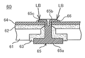
상술한 종래 기술의 문제점을 해결하기 위하여, 하기 특허문헌 2에는 특정한 형상을 가지는 가공 펀치를 이용하여 단자의 카시메부의 선단쪽을 성형함으로써, 집전체와 카시메부의 선단 간에 틈새가 생기지 않도록 하고 나서, 이 카시메부의 선단에 대해서 레이저 광을 조사하여 단자와 집전체를 레이저 용접하도록 이루어진 예를 나타내고 있다. 이 하기 특허문헌 2에 개시되어 있는 집전체와 카시메부의 레이저 용접 방법을 도 7을 이용하여 설명한다. 또한, 도 7a는 하기 특허문헌 2에 개시되어 있는 단자의 카시메부의 선단 가공 공정을 나타내는 단면도이며, 도 7b는 도 7a의 공정 후에 레이저 용접하는 공정을 나타내는 도면이다.In order to solve the above-mentioned problems of the prior art, Patent Document 2 below uses a processing punch having a specific shape to shape the tip side of the casing portion of the terminal so that there is no gap between the current collector and the tip of the casing portion. The example which consists of irradiating a laser beam with respect to the front end of this casing part and carrying out laser welding of a terminal and an electrical power collector is shown. The laser welding method of the electrical power collector and the casime part which are disclosed by this following patent document 2 is demonstrated using FIG. 7A is sectional drawing which shows the front-end | tip process of the casing part of the terminal disclosed by following patent document 2, and FIG. 7B is a figure which shows the process of laser welding after the process of FIG. 7A.
하기 특허문헌 2에 개시되어 있는 집전체와 단자의 접합부 (60)는 전지 외장체 (도시하지 않음)에 고정되는 뚜껑판 (61)과, 내측 절연 봉지재 (62) 및 외부 절연 봉지재 (63)와, 발전 요소에 접속된 집전체 (64)와, 리벳 단자 (65)를 구비하고 있다. 내측 절연 봉지재 (62) 및 외부 절연 봉지재 (63)는 관통공을 가지며, 뚜껑판 (61)에 형성된 개공의 내외 양 주변 테두리부에 배치되어 있다. 집전체 (64)는 내측 절연 봉지재 (62)에 겹쳐 배치되어 있다. 리벳 단자 (65)는 턱부 (65a)로부터 돌접한 리벳부 (65b)를 가지고 있다.The
그리고 이 접합부 (60)는 리벳 단자 (65)의 카시메부 (65b)를 뚜껑판 (61)의 외주쪽에서부터 외부 절연 봉지재 (63), 뚜껑판 (61)의 개구, 내측 절연 봉지재 (62) 및 집전체 (64)의 리벳 단자공을 관통하도록 조립되고, 다음에 리벳 단자 (65)의 카시메부 (65b)를 집전체 (64)를 압압하도록 카시메함으로써 일체화되어 있다. 여기까지의 공정은 실질적으로 도 6에 나타낸 하기 인용문헌 1에 개시되어 있는 것과 마찬가지이다. 다음에, 리벳 단자 (65)의 카시메부 (65b)와 상보적인 오목부를 가지며, 이 오목부의 주변 테두리부에 소정 각도의 경사부 (A1)를 가지는 가공 펀치 (A)를 준비한다. 그리고 가공 펀치 (A)를 카시메부 (65b)의 선단 (65c)에 경사부 (A1)가 맞닿도록 밀어 넣고, 카시메부 (65b)의 선단 (65c)을 부분적으로 변형 가공시켜, 도 7b에 나타낸 것처럼 카시메부 (65b)의 선단 (65c)이 원뿔대부가 되도록 성형한다. 이에 의해, 카시메부 (65b)의 선단 (65c)의 형상은 둔각으로 조정된다.And this
다음에, 카시메부 (65b)의 선단 (65c)의 원뿔대부의 윗면의 수직 방향 또는 그 부근의 방향에서 레이저 광 (LB)을 조사함으로써, 레이저 용접을 실시한다. 이때의 레이저 광 (LB)의 조사 범위는 적어도 집전체 (64)와 카시메부 (65b)의 선단 (65c)의 원뿔대부를 포함한 영역으로 한다. 이 레이저 용접에 의해, 집전체 (64)와 카시메부 (65b)의 선단 (65c)의 원뿔대부의 쌍방으로 조사된 레이저의 에너지가 치우침 없이 전달되어, 용접부에는 양호한 용접 스폿부 (너겟) (66)가 형성된다는 것이다.Next, laser welding is performed by irradiating the laser beam LB in the direction of the vertical direction of the upper surface of the truncated conical part of the
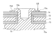
또한, 상술한 종래 기술의 문제점을 해결하기 위해, 하기 특허문헌 3에는 리벳 단자의 카시메부를 특정한 형상을 가지는 가공 펀치를 이용하여 단자의 카시메부의 선단쪽을 박육 (薄肉)으로 성형함과 동시에, 집전체와 카시메부의 선단 간에 틈새가 생기지 않도록 하고 나서, 이 카시메부의 박육부에 대해서 레이저 광을 조사하여 단자와 집전체를 레이저 용접하도록 한 예를 나타내고 있다. 이 하기 특허문헌 3에 개시되어 있는 집전체와 카시메부의 레이저 용접 방법을 도 8을 이용해 설명한다. 또한, 도 8a는 하기 특허문헌 3에 개시되어 있는 리벳 단자의 카시메 공정 후의 상태를 나타내는 단면도이며, 도 8b는 도 8a의 공정 후에 레이저 용접하는 공정을 나타내는 도면이다.In addition, in order to solve the above-mentioned problems of the prior art, Patent Document 3 below uses a processing punch having a specific shape of the rivet terminal to shape the tip side of the casing portion of the terminal into thin and An example is shown in which the gap between the current collector and the tip of the casing portion is prevented from occurring, and then the thin portion of the casing portion is irradiated with laser light to laser weld the terminal and the current collector. The laser welding method of the electrical power collector and the casime part which are disclosed by this following patent document 3 is demonstrated using FIG. 8A is sectional drawing which shows the state after the casime process of the rivet terminal disclosed by following patent document 3, and FIG. 8B is a figure which shows the process of laser welding after the process of FIG. 8A.
하기 특허문헌 3에 개시되어 있는 집전체와 단자의 접합부 (70)도 전지 외장체 (도시하지 않음)에 고정되는 뚜껑판 (71)과, 내측 절연 봉지재 (72) 및 외부 절연 봉지재 (73)와, 발전 요소에 접속된 집전체 (74)와, 리벳 단자 (75)를 구비하고 있다. 내측 절연 봉지재 (72) 및 외부 절연 봉지재 (73)는 관통공을 가지며, 뚜껑판 (71)에 형성된 개공의 내외 양 주변 테두리부에 배치되어 있다. 집전체 (74)는 내측 절연 봉지재 (72)에 거듭 배치되어 있다. 리벳 단자 (75)는 턱부 (75a)로부터 돌접한 카시메부 (75b)를 가지고 있다.The
그리고 이 접합부 (70)는 리벳 단자 (75)의 카시메부 (75b)를 뚜껑판 (71)의 외주쪽에서부터 외부 절연 봉지재 (73)의 관통공, 뚜껑판 (71)의 개구, 내측 절연 봉지재 (72) 및 집전체 (74)의 리벳 단자공을 관통하도록 조립하고, 이어서 리벳 단자 (75)의 카시메부 (75b)를 집전체 (74)를 압압하도록 카시메함으로써 일체화되어 있다. 이때 카시메용 치구로서 주변부가 환상으로 돌출하고 있는 펀치를 사용하면, 리벳 단자 (75)의 카시메부 (75b)에는 환상으로 두께가 얇은 박육부 (75d)가 형성된다. 그러면, 리벳 단자 (75)의 카시메부 (75b)의 박육부 (75d)는 집전체 (74)와 충분히 밀착함과 동시에, 환상으로 표면이 평평한 부분이 형성된다.And this
다음에, 카시메부 (75b)의 박육부 (75d)에 있어서, 수직 방향 또는 그 부근의 방향에서 레이저 광 (LB)을 조사함으로써 레이저 용접을 실시한다. 이때의 레이저 광 (LB)의 조사 범위는 리벳 단자 (75)의 카시메부 (75b)의 박육부 (75d)이면 어디라도 된다. 이 레이저 용접에 의해, 설령 레이저 광의 조사 위치가 어긋나도 카시메부 (75b)의 박육부 (75d)의 표면에 레이저가 확실하게 조사되므로 용접부에는 양호한 너겟 (76)이 형성된다는 것이다.Next, in the
상기 특허문헌 2에 개시되어 있는 접합부 (60)의 구성에 의하면, 레이저 광은 용접부의 윗쪽부터 조사할 수 있으므로, 복수 개소를 대칭으로 레이저 용접하는 경우에도 접합부를 회전시키는 일 없이 용접할 수 있다고 하는 이점이 있다. 하지만, 집전체 (64)와 카시메부 (65b)의 선단 (65c)의 원뿔대부를 포함하는 영역을 용접하고 있기 때문에 레이저 조사 위치가 카시메부쪽으로 어긋나면 카시메부 (65b)의 두께가 두껍기 때문에 양호한 용접을 실시할 수 없게 되고, 또 레이저 조사 위치가 집전체 (64) 쪽으로 어긋나면 용접 부분이 작아지기 때문에 용접부의 강도가 작아진다고 하는 문제점이 존재한다.According to the structure of the
또, 상기 특허문헌 3에 개시되어 있는 접합부 (70)의 구성에 의하면, 상기 특허문헌 2에 개시되어 있는 접합부 (60)의 경우와 마찬가지의 이점을 가지는 것 외에 레이저 용접 위치가 어긋나도 카시메부 (75b)의 두께가 얇기 때문에 양호하게 단자부와 집전체를 레이저 용접하는 것이 가능하다는 이점도 존재하고 있다. 하지만, 상기 특허문헌 3에 개시되어 있는 접합부 (70)는 레이저 광의 조사에 의해서 카시메부 (75b)의 용융 부분이 카시메부 (75b)를 관통한 후에 집전체 (74)가 용융하게 되기 때문에, 레이저 광의 출력을 크게 할 필요가 있는 것 외에 용접 강도를 강하게 하기 위해서는 레이저 광의 조사 시간을 길게 할 필요가 있다고 하는 문제점이 존재한다.Moreover, according to the structure of the
본 발명은 상술한 바와 같은 종래 기술의 문제점을 해결하기 위하여 이루어진 것으로서, 단자와 집전체의 레이저 광이나 전자빔 등의 고에너지선에 의한 용접에 있어서, 고에너지선의 출력을 그다지 크게 하지 않아도 단시간에 확실히 용접을 실시할 수 있고, 설령 고에너지선의 조사 위치가 조금 어긋나더라도 고강도의 용접을 실시할 수 있는 접합부를 구비한 2차 전지를 제공하는 것을 목적으로 한다.SUMMARY OF THE INVENTION The present invention has been made to solve the problems of the prior art as described above. In welding by high energy rays such as laser light or electron beam of a terminal and a current collector, the output of the high energy ray is surely shortened without a great increase. It is an object of the present invention to provide a secondary battery provided with a joining portion which can be welded, and even if the irradiation position of a high energy ray is slightly shifted.
상기 목적을 달성하기 위하여, 본 발명의 2차 전지는 단자가 봉구판에 부착되고, 상기 봉구판이 내부에 전극체를 가지는 외장 캔의 개구부에 밀봉 상태로 고정되며, 상기 단자와 상기 전극체의 집전체가 전기적으로 접속되어 있는 2차 전지에 있어서, 상기 단자는 날밑부 (鍔部)의 한쪽 면이 단자부가 되고, 상기 날밑부의 다른쪽 면에 원통상의 카시메 부재가 각각 형성되어, 상기 원통상의 카시메 부재는 제1 절연부재, 상기 봉구판, 제2 절연부재 및 상기 집전체 각각에 형성된 개구부에 삽통되고, 상기 원통상의 카시메 부재의 선단쪽은 상기 집전체에 형성된 카운터보어 (counterbore) 내에서 확경 (擴徑) 방향으로 카시메되어 있음과 동시에, 상기 카시메 부재의 단부 (端部)에 형성된 다른 부분보다도 박육화된 박육부가 상기 집전체의 카운터보어 내에 감합되고, 상기 단자의 날밑부와, 상기 제1 절연부재와, 상기 봉구판과, 상기 제2 절연부재와, 상기 집전체가 기계적으로 고정되고 있으며, 또한 상기 카시메 부재의 박육부와 상기 집전체의 카운터보어의 감합부가 고에너지선에 의해 용접되어 있는 것을 특징으로 한다.In order to achieve the above object, in the secondary battery of the present invention, a terminal is attached to a sealing plate, and the sealing plate is fixed in a sealed state to an opening of an exterior can having an electrode body therein, and the terminal and the electrode body are housed. In the secondary battery in which the whole is electrically connected, the said terminal has one side of a blade part as a terminal part, and a cylindrical casime member is formed in the other surface of the said blade part, respectively, A conventional casime member is inserted into an opening formed in each of the first insulating member, the sealing plate, the second insulating member, and the current collector, and the tip side of the cylindrical casime member is formed by a counterbore formed in the current collector ( While thinning in the counterbore in the diameter direction and thinner than other portions formed in the end of the casme member, the thinned portion is wound in the counterbore of the current collector. And the blade base of the terminal, the first insulating member, the sealing plate, the second insulating member, and the current collector are mechanically fixed, and the thin part of the casme member and the current collector. The fitting portion of the counterbore is welded by a high energy ray.
본 발명의 2차 전지에 있어서는, 단자의 원통상의 카시메 부재의 선단쪽은 집전체에 형성된 카운터보어 내에서 확경 방향으로 카시메되어 있음과 동시에, 카시메 부재의 단부에 형성된 다른 부분보다도 박육화된 박육부가 집전체의 카운터보어 내에 감합되고, 단자의 날밑부와, 제1 절연부재와, 봉구판과, 제2 절연부재와, 집전체가 기계적으로 고정되어 있기 때문에 단자와 집전체가 기계적으로 강고하게 고정되어 있으므로, 단자와 집전체 간의 전기 저항이 낮아진다. 게다가, 본 발명의 2차 전지에 있어서는 카시메 부재의 단부의 박육부가 집전체의 카운터보어 내에 감합되어 있기 때문에 진동이 가해져도 단자와 집전체가 움직이기 어려워져 단자와 집전체 간의 전기 저항의 변동이 적게 된다.In the secondary battery of the present invention, the tip side of the cylindrical casime member of the terminal is cassime in the diameter direction in the counterbore formed in the current collector, and is thinner than other portions formed at the ends of the casime member. The thin thin portion is fitted into the counterbore of the current collector, and the terminal and the current collector are mechanically fixed because the blade base of the terminal, the first insulating member, the sealing plate, the second insulating member, and the current collector are mechanically fixed. Since it is firmly fixed, the electrical resistance between the terminal and the current collector is lowered. In addition, in the secondary battery of the present invention, since the thin portion at the end of the casing member is fitted into the counterbore of the current collector, the terminal and the current collector become difficult to move even if vibration is applied, and thus the electrical resistance between the terminal and the current collector is reduced. There is little variation.
아울러, 본 발명의 2차 전지에 있어서는, 카시메 부재의 단부의 박육부와 집전체의 카운터보어의 감합부가 레이저 광이나 전자빔 등의 고에너지선에 의해 용접되어 있다. 이 고에너지선에 의한 용접 개소에서는 카시메 부재의 단부의 박육부 표면과 집전체 표면이 직접 용융함으로써 용접되어 있기 때문에, 용융 심도가 얕아도 용접부의 용접 강도는 강고하게 되므로, 고에너지선의 출력은 종래예의 것에 비하여 약해도 되고, 또 고에너지선의 조사 시간은 짧아도 되므로 에너지 절약적으로 제조할 수 있게 된다. 아울러, 본 발명의 2차 전지에 의하면 고에너지선을 카시메 부재의 단부의 박육부와 집전체의 카운터보어의 감합부의 윗쪽에서부터 조사함으로써 용접할 수 있으므로, 대칭적으로 고에너지선에 의해 용접하는 경우에도 고에너지선을 조사하기 위한 조사 헤드를 이동시키는 것만으로 해결되기 때문에 제조 효율이 향상한다.In addition, in the secondary battery of this invention, the thin part of the edge part of a casme member and the fitting part of the counterbore of an electrical power collector are welded by high energy rays, such as a laser beam and an electron beam. In the welding position by this high energy ray, since the thin part surface and the collector surface of the edge part of a casmeme member are welded by direct melting, the welding strength of a weld part becomes strong, even if a melt depth is shallow, and the output of a high energy ray is Since it may be weak compared with the conventional example, and the irradiation time of a high energy ray may be short, it can manufacture energy-savingly. In addition, according to the secondary battery of the present invention, since the high energy ray can be welded by irradiating the thin portion at the end of the casime member and the fitting portion of the counterbore of the current collector, the high energy ray is symmetrically welded by the high energy ray. Even in this case, the manufacturing efficiency is improved because it is solved only by moving the irradiation head for irradiating high energy rays.
또한, 본 발명의 2차 전지는 리튬 이온 전지와 같은 비수 전해질 2차 전지 및 니켈 수소 2차 전지와 같은 수성 전해질 2차 전지 중 어느 쪽에 대해서도 적용 가능하다. In addition, the secondary battery of the present invention can be applied to either a nonaqueous electrolyte secondary battery such as a lithium ion battery and an aqueous electrolyte secondary battery such as a nickel hydrogen secondary battery.
또, 본 발명의 2차 전지에 있어서는 상기 카시메 부재의 단부에 형성된 다른 부분보다도 박육화된 박육부는 상기 카시메 부재의 주변에 부분적으로 형성되어 있는 것이 바람직하다.Moreover, in the secondary battery of this invention, it is preferable that the thin part thinned rather than the other part formed in the edge part of the said casing member is formed in the periphery of the said casing member.
카시메 부재의 단부의 박육부를 주연 테두리부의 전체 주변에 걸쳐서 형성하기 위해서는 카시메 부재의 단부를 박육화할 때 펀치압을 크게 할 필요가 있고, 게다가 펀치압의 증가는 펀치 수명의 저하 및 카시메 부재에 대한 스트레스 증가를 일으키는 원인이 된다. 본 발명의 2차 전지에 의하면, 카시메 부재의 단부의 박육부를 카시메 부재의 주변에 부분적으로 형성되어 있는 것으로 했으므로, 펀치 압력을 낮추어도 양호하게 카시메 부재의 단부를 박육화할 수 있고, 게다가 카시메 부재의 단부의 박육부와 집전체의 카운터보어의 감합부를 전체 주변에 걸쳐서 고에너지선에 의해서 용접하지 않아도 단자와 집전체 간의 저항값이 포화 상태가 되기 때문에 상기 효과를 양호하게 나타내면서도, 고에너지선에 의한 용접 개소의 저감에 수반하여 제조 효율이 향상된다. 또한, 카시메 부재의 단부에 형성된 다른 부분보다도 박육화된 박육부는 전체 주변에 대해서 1/2 이하가 바람직하다.In order to form the thin portion of the end of the casing member over the entire periphery of the peripheral edge portion, it is necessary to increase the punch pressure when the end of the casing member is thinned, and further, the increase in the punch pressure results in a decrease in the punch life and Causes increased stress on absence. According to the secondary battery of the present invention, since the thin portion at the end of the casme member is formed partially around the casme member, the end of the casme member can be thinned even if the punch pressure is lowered. In addition, even when the thin portion at the end of the Cassime member and the fitting portion of the counterbore of the current collector are not welded by high-energy rays over the entire periphery, the resistance value between the terminal and the current collector becomes saturated, and thus the above effect is satisfactory. With the reduction of the welding point by high energy ray, manufacturing efficiency improves. In addition, the thin portion thinner than other portions formed at the end of the casime member is preferably 1/2 or less with respect to the entire periphery.
또, 본 발명의 2차 전지에 있어서는 상기 카운터보어의 평면시 (平面視)의 형상은 원형상 또는 타원 형상이며, 상기 카시메 부재의 단부에 형성된 다른 부분보다도 박육화된 박육부에서의 단자의 중심쪽의 상기 다른 부분과의 단차부의 평면시의 형상은 상기 카운터보어의 테두리와 동일한 방향으로 만곡하는 원호상으로 되어 있는 것이 바람직하다.Moreover, in the secondary battery of this invention, the shape of the planar view of the said counterbore is circular or elliptical shape, and the center of the terminal in the thin part thinner than the other part formed in the edge part of the said casing member It is preferable that the planar shape of the stepped portion with the other part on the side is an arc shape that curves in the same direction as the edge of the counterbore.
카운터보어의 평면시의 형상이 원형상 또는 타원 형상이면, 카시메 부재의 단부의 박육부를 카시메 부재의 일부에만 형성하는 경우 단자 중심쪽이 직선 형상이 되도록 펀치에 의해 박육화하면 카운터보어의 테두리와 박육화한 부분의 최외주쪽의 간격이 일정하지 않게 되고, 박육화한 부분의 최외주쪽의 양단부에 있어서 카운터보어의 테두리와 박육화한 카시메 부재의 단부 간의 틈새 폭이 커져 고에너지선에 의해서 용접할 수 있는 범위가 좁아져 버린다. 본 발명의 2차 전지에 있어서는 카시메 부재의 단부에 형성된 다른 부분보다도 박육화된 박육부에서의 단자 중심쪽의 상기 다른 부분 단차부의 평면시의 형상은 카운터보어의 테두리와 같은 방향으로 만곡하는 원호상으로 되어 있다. 그 때문에, 카시메 부재의 단부에 형성된 다른 부분보다도 박육화된 박육부의 평면시의 형상은 원호상 평면이 된다. 본 발명의 2차 전지에 의하면, 박육화한 카시메 부재의 최외주쪽이 카운터보어의 테두리에 실질적으로 따르도록 형성할 수 있기 때문에 용접 범위를 넓게 할 수 있게 된다.If the planar shape of the counterbore is circular or elliptical, when the thin portion at the end of the casme member is formed only in a part of the casme member, the edge of the counterbore is thinned by a punch so that the terminal center is straight. The gap between the outermost circumference of the thinned portion and the outermost circumference becomes inconsistent, and the gap width between the edge of the counterbore and the end of the thinned Kashime member increases at both ends of the outermost circumference of the thinned portion and is welded by a high energy ray. The range that we can do becomes narrow. In the secondary battery of the present invention, the planar shape of the stepped portion of the other portion of the thinner portion thinner than the other portion formed at the end of the casme member is curved in the same direction as the edge of the counterbore. It is. Therefore, the shape at the time of planarization of the thin part thinner than the other part formed in the edge part of the casime member becomes an arc-shaped plane. According to the secondary battery of the present invention, the outermost circumferential side of the thinned casime member can be formed to substantially conform to the edge of the counterbore, so that the welding range can be widened.
또, 본 발명의 2차 전지에 있어서는, 상기 단자의 중심에서부터 상기 박육부의 방향으로 직선을 그었을 때, 상기 단자의 중심에서부터 상기 직선과 상기 박육부의 단자 중심쪽의 단차부가 교차하는 점까지의 거리를 L1로 하고, 상기 단자 중심에서부터 상기 직선과 카운터보어의 테두리가 교차하는 점까지의 거리를 L2로 했을 때, L1/L2가 0.5 이상 1.0 미만인 관계를 만족시키고, 또 부분적으로 형성한 상기 박육부 전체에 걸쳐 상기 관계를 만족시키고 있는 것이 바람직하다.In the secondary battery of the present invention, when a straight line is drawn in the direction of the thin part from the center of the terminal, the distance from the center of the terminal to the point where the stepped portion of the straight line and the terminal center side of the thin part intersect is crossed. When the distance is L1 and the distance from the center of the terminal to the point where the edge of the straight line and the counterbore intersects is L2, the foil that satisfies the relationship that L1 / L2 is 0.5 or more and less than 1.0 and is partially formed It is preferable to satisfy the said relationship throughout the meat part.
단자 중심에서부터 다른 부분보다도 박육화된 박육부의 방향으로 직선을 그었을 때, L1/L2가 0.5 이상 1.0 미만인 관계를 만족시키고, 또 부분적으로 형성한 박육부 전체에 걸쳐 상기 관계를 만족시키도록 하면, 카시메 부재의 단부에 형성된 다른 부분보다도 박육화된 박육부가 카운터보어의 테두리에 실질적으로 따르도록 형성할 수 있어 레이저 용접할 수 있는 영역의 길이를 길게 할 수 있기 때문에 양호하게 고에너지선에 의해서 용접할 수 있게 된다. 또한, L1/L2가 0.5 미만이면 카시메 부재의 단부의 박육화된 박육부에서의 단자 중심쪽의 다른 부분과의 단차부의 평면시의 형상을 원호상으로 한 것의 효과가 나타나기 어려워진다. 보다 바람직한 L1/L2의 수치 범위는 0.9 이상 1.0 미만이다. 부분적으로 형성한 박육부 전체에 걸쳐 L1/L2가 0.9 이상 1.0 미만이라는 관계를 만족할 수 있도록 하면, 이 부분적으로 형성한 박육부와 카운터보어 테두리 간에 실질적으로 틈새가 생기지 않는 상태로 할 수 있어, 보다 양호하게 고에너지선에 의해 용접할 수 있게 된다.When a straight line is drawn from the center of the terminal in the direction of the thinned portion thinner than other portions, the relationship L1 / L2 is 0.5 or more and less than 1.0, and the above relationship is satisfied throughout the partially formed thin portion. Thinner thinner than other portions formed at the end of the member can be formed so as to substantially conform to the edge of the counterbore, so that the length of the laser weldable area can be lengthened. It becomes possible. Moreover, when L1 / L2 is less than 0.5, the effect of having the arc shape of the planar shape of the step part with the other part of the terminal center side in the thinned thin part of the edge part of a casme member becomes difficult to appear. More preferably, the numerical range of L1 / L2 is 0.9 or more and less than 1.0. By satisfying the relation that L1 / L2 is 0.9 or more and less than 1.0 over the partially formed thin portion, the gap between the partially formed thin portion and the counterbore rim can be made to be substantially free. It is possible to weld by a high energy ray preferably.
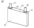
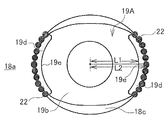
도 1은 각 실시 형태에 공통되는 실시 형태에 관한 2차 전지의 사시도이다.
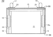
도 2a는 도 1의 2차 전지의 내부 구조를 나타내는 정면도이며, 도 2b는 도 2a의 ⅡB-ⅡB선에 따른 단면도이다.
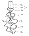
도 3은 각 실시 형태에 공통되는 단자의 조립 전 사시도이다.
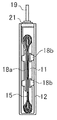
도 4는 각 실시 형태에 공통되는 단자를 조립한 후에 레이저 용접한 후의 부분 단면도이다.
도 5a는 제1 실시 형태의 용접 후 단자의 평면도이며, 도 5b는 제2 실시 형태의 용접 후 단자의 평면도이다.
도 6a는 종래예의 집전체와 단자부의 접합부를 상하 반대로 해서 나타낸 단면도이며, 도 6b는 도 6a의 레이저 용접 전 집전체와 단자의 접합부의 단면도이다.
도 7a는 다른 종래예의 단자의 카시메부의 선단 가공 공정을 나타내는 단면도이며, 도 7b는 도 7a의 공정 후 레이저 용접한 공정을 나타내는 도면이다.
도 8a는 또 다른 종래예의 리벳 단자의 카시메 공정 후의 상태를 나타내는 단면도이며, 도 8b는 도 8a의 공정 후에 레이저 용접하는 공정을 나타내는 도면이다.1 is a perspective view of a secondary battery according to an embodiment common to each embodiment.
FIG. 2A is a front view illustrating the internal structure of the rechargeable battery of FIG. 1, and FIG. 2B is a cross-sectional view taken along line IIB-IIB of FIG. 2A.
3 is a perspective view before assembly of a terminal common to each embodiment.
4 is a partial sectional view after laser welding after assembling the terminals common to each embodiment.
5A is a plan view of the post-welding terminal of the first embodiment, and FIG. 5B is a plan view of the post-welding terminal of the second embodiment.
Fig. 6A is a cross-sectional view showing the junction of the current collector and the terminal portion of the conventional example upside down.
It is sectional drawing which shows the front end process of the casing part of the terminal of another conventional example, and FIG. 7B is a figure which shows the process which carried out the laser welding after the process of FIG.
FIG. 8A is a cross-sectional view showing a state after a casime step of the rivet terminal of another conventional example, and FIG. 8B is a view showing a step of laser welding after the step of FIG. 8A.
이하, 본 발명의 각 실시 형태를 도면을 이용해 설명한다. 다만, 이하에 나타내는 실시 형태는 본 발명의 기술 사상을 구체화하기 위한 2차 전지로서, 고에너지선으로 레이저 광을 사용하여 단자와 집전체를 용접한 각형 비수 전해질 2차 전지를 예시하는 것이며, 본 발명을 이 각형 비수 전해질 2차 전지로 특정하는 것을 의도하는 것이 아니고, 특허 청구 범위에 포함되는 그 외의 실시 형태의 것도 동일하게 적응할 수 있는 것이다.EMBODIMENT OF THE INVENTION Hereinafter, each embodiment of this invention is described using drawing. However, the embodiment shown below is a secondary battery for incorporating the technical idea of this invention, and illustrates the square nonaqueous electrolyte secondary battery which welded the terminal and the electrical power collector using the laser beam with high energy ray, It is not intended to identify the invention as this rectangular nonaqueous electrolyte secondary battery, and other embodiments included in the claims can be similarly adapted.
최초로 본 발명의 각 실시 형태에 공통되는 2차 전지로서의 각형 비수 전해질 2차 전지를 도 1∼도 4를 이용하여 설명한다. 또한, 본 발명에 있어서는 용접에 사용하는 고에너지선으로는 레이저 광 및 전자빔 중 어느 쪽도 사용할 수 있지만, 이하에서는 레이저 광으로 대표하여 설명한다.First, a rectangular nonaqueous electrolyte secondary battery as a secondary battery common to each embodiment of the present invention will be described with reference to FIGS. 1 to 4. In the present invention, either a laser light or an electron beam can be used as the high energy ray used for welding. Hereinafter, the laser light will be described as representative.
이 비수 전해질 2차 전지 (10)는 정극극판과 부극극판이 세퍼레이터 (모두 도시 생략)를 통하여 권회된 편평상의 권회전극체 (11)를 각형의 전지 외장 캔 (12)의 내부에 수용하고, 봉구판 (13)에 의해서 전지 외장 캔 (12)을 밀폐한 것이다.This nonaqueous electrolyte
정극극판은 알루미늄박으로 이루어진 정극심체의 양면에 띠 모양의 알루미늄박이 노출되어 있는 정극심체 노출부 (14)가 형성되도록, 정극 활물질합제를 도포하고, 건조 후에 압연함으로써 제작되어 있다. 또, 부극극판은 구리박으로 이루어진 부극심체의 양면에 띠 모양의 구리박이 노출되어 있는 부극심체 노출부 (15)가 형성되도록 부극 활물질합제를 도포하고, 건조 후에 압연함으로써 제작되어 있다. 그리고 편평상의 권회전극체 (11)는 정극극판 및 부극극판을 권회축 방향의 양 단부에 정극심체 노출부 (14) 및 부극심체 노출부 (15)가 각각 위치하도록 폴리에틸렌제의 다공질 세퍼레이터 (도시 생략)를 통하여 편평상으로 권회함으로써 제작되어 있다.The positive electrode plate is produced by applying a positive electrode active material mixture and rolling after drying so as to form the positive electrode core exposed
이 중, 정극심체 노출부 (14)는 정극집전체 (16)를 통하여 정극단자 (17)에 접속되고, 부극심체 노출부 (15)는 부극집전체 (18a)를 통하여 부극단자 (19)에 접속되어 있다. 정극단자 (17), 부극단자 (19)는 각각 절연부재 (20, 21)를 통하여 봉구판 (13)에 고정되어 있다. 이 비수 전해질 2차 전지 (10)는 편평상의 권회전극체 (11)를 각형의 전지 외장 캔 (12) 내에 삽입한 후, 봉구판 (13)을 전지 외장 캔 (12)의 개구부에 레이저 용접하고, 그 후 전해액 주액공 (도시 생략)으로부터 비수 전해액을 주액하고, 이 전해액 주액공을 밀폐함으로써 제작되어 있다.Among these, the positive electrode core exposed
여기에서, 정극단자 (17) 및 부극단자 (19)의 구체적 구성에 대하여 설명을 하지만, 통상은 정극집전체 (16)가 알루미늄 금속으로 형성되어 있고, 부극집전체 (18a)가 구리 금속으로 형성되어 있다는 점에서 서로 상이하지만, 그 외의 구성은 실질적으로 동일한 것으로, 부극단자 (19)로 대표하여 설명한다.Here, although the specific structure of the
이 부극단자 (19)는 도 3에 나타낸 것처럼, 날밑부 (19a)의 한쪽 방향에 형성된 원통상의 카시메 부재 (19b)와, 날밑부 (19a)의 다른 단쪽 방향에 형성된 단자부 (19c)를 구비하고 있다.As shown in Fig. 3, the
이 원통상의 카시메 부재 (19b)는 제1 절연체로서 개스킷 (21a), 봉구판 (13), 제2 절연체로서 절연부재 (21b) 및 부극집전체 (18a)에 각각 형성된 개구부 내에 삽통되어 조립된다. 또한, 부극집전체 (18a)로는 도 4에 나타낸 바와 같이 부극단자 (19)의 카시메 부재 (19b)가 삽통되는 개구부의 주위에 카운터보어 (18c)가 형성되어 있는 것을 사용하고 있다.This cylindrical casime
이 조립된 상태에서 단자부 (19c)가 하향되도록 도시하지 않은 치구 (Jig) 상에 재치하고, 카시메 부재 (19b)의 선단쪽에서 동일한 방향으로 확경하도록 카시메함과 동시에, 카시메 부재 (19b)의 선단쪽에 다른 카시메 부재 (19b) 보다도 두께가 얇은 박육부 (19d)가 부분적으로 형성되도록 성형한다. 그러면, 카시메 부재 (19b) 단부의 박육부 (19d)는 도 4에 나타낸 것처럼 부극집전체 (18a)와 충분히 밀착하여 표면이 평평하게 됨과 동시에, 카시메 부재 (19b) 단부의 박육부 (19d)는 부극집전체 (18a)의 카운터보어 (18c) 내에 감합된 상태가 된다. 이 상태에서 카시메 부재 (19b) 단부의 박육부 (19d)와 부극집전체 (18a)의 카운터보어 (18c)의 감합부에 레이저 광 (LB)을 조사하고, 카시메 부재 (19b) 단부의 박육부 (19d) 표면과 부극집전체 (18a) 표면을 직접 용융시켜 레이저 용접을 실시함으로써, 각 실시 형태에 공통되는 부극단자 (19)가 얻어진다. 또한, 참조 부호 22는 레이저 용접에 의해서 형성된 너겟을 나타낸다.In this assembled state, the
이 각 실시 형태에 공통되는 부극단자 (19)에 있어서는, 부극단자 (19)의 원통상의 카시메 부재 (19b)의 선단쪽은 부극집전체 (18a)에 형성된 카운터보어 (18c) 내에서 확경 방향으로 카시메되어 있음과 동시에, 다른 부분보다도 박육화된 박육부 (19d)가 형성되며, 이 박육부 (19d)는 부극집전체 (18a)의 카운터보어 (18c) 내에 감합되어 있다. 또한, 부극단자 (19)의 날밑부 (19a)와, 개스킷 (21a)과, 봉구판 (13)과, 절연부재 (21b)와, 부극집전체 (18a)는 서로 기계적으로 고정된 상태로 되어 있다. 그 때문에, 부극단자 (19)와 부극집전체 (18a)는 기계적으로 강고하게 고정되어 있다. 또한, 카시메 부재 (19b) 단부의 박육부 (19d)가 부극집전체 (18a)의 카운터보어 (18c) 내에 감합되어 있기 때문에, 진동이 가해져도 부극단자 (19)와 부극집전체 (18a)가 보다 움직이기 어려워진다.In the
또, 이 부극단자 (19)에 있어서는, 카시메 부재 (19b) 단부의 박육부 (19d)와 부극집전체 (18a)의 카운터보어 (18c)의 감합부가 카시메 부재 (19b) 단부의 박육부 (19d) 표면과 부극집전체 (18a) 표면이 직접 용융하도록 레이저 용접되어 있다. 그 때문에, 용융 심도가 얕아도 용접부의 용접 강도는 강고하게 되므로 레이저 광의 출력은 종래예의 것에 비해서 약한 것이라도 양호하게 레이저 용접을 실시할 수 있고, 게다가 레이저 광의 조사 시간은 짧아도 되므로 에너지 절약적으로 제조할 수 있게 된다. 또한, 레이저 광을 카시메 부재 (19b) 단부의 박육부 (19d)와 부극집전체 (18a)의 카운터보어 (18c)의 감합부의 윗쪽으로부터 조사함으로써 용접할 수 있으므로, 좌우 대칭적으로 레이저 용접할 필요가 있는 경우에도 레이저 광을 조사하기 위해서 레이저 헤드를 이동시키는 것만으로 용접할 수 있게 된다.Moreover, in this
또한, 카시메 부재 (19b) 단부의 박육부 (19d)는 레이저 용접하는 개소에만 형성하면 되기 때문에, 반드시 카시메 부재 (19b) 주변의 전체 주변에 걸쳐 형성할 필요가 없다. 카시메 부재 (19b) 단부의 박육부 (19d)를 카시메 부재 (19b)의 단부 전체 주변에 걸쳐 형성하려면 성형 펀치에 인가하는 펀치압을 크게 할 필요가 있지만, 펀치압의 증가는 펀치 수명의 저하 및 카시메 부재 (19b)에 대한 스트레스 증가를 일으키는 원인이 된다. 그것과는 대조적으로, 카시메 부재 (19b) 단부의 박육부 (19d)를 카시메 부재 (19b) 주변에 부분적으로 형성하면, 성형 펀치에 인가하는 펀치압을 작게 해도 양호하게 박육부 (19d)를 형성하는 것이 가능하게 된다.
Moreover, since the
[제1 실시 형태][First Embodiment]
제1 실시 형태의 부극단자 (19A)의 구성을 도 5a를 이용하여 설명한다. 제1 실시 형태의 부극단자 (19A)는 카시메 부재 (19b)의 선단쪽에 다른 카시메 부재 (19b) 보다도 두께가 얇은 박육부 (19d)가 부분적으로 형성되도록 성형할 때, 성형 펀치로서 부분적으로 원환상의 돌기가 형성되어 있는 것을 사용한 것이다. 또한, 부극집전체 (18a)에 형성하는 카운터보어 (18c)의 평면시의 형상은 원형상 내지 타원 형상으로 되지만, 제1 실시 형태의 부극단자 (19a)에서는 도 5a에 나타낸 것처럼, 평면시에서 타원 형상의 카운터보어 (18c)가 채용되어 있다. 그리고 부분적으로 원환상의 돌기가 형성되어 있는 성형 펀치를 사용하여 부극단자 (19A)의 중심에서부터 박육부 (19d)의 방향으로 직선을 그었을 때, 부극단자 (19A)의 중심에서부터 직선과 박육부 (19d)의 부극단자 (19A) 중심쪽의 단차부 (19e)가 교차하는 점까지의 거리를 L1로 하고, 부극단자 (19A)의 중심에서부터 직선과 카운터보어 (18c)의 테두리가 교차하는 점까지의 거리를 L2로 했을 때, L1/L2가 0.5 이상 1.0 미만인 관계를 만족시키고, 또한 부분적으로 형성한 박육부 (19d) 전체에 걸쳐 L1/L2가 0.5 이상 1.0 미만이라는 관계를 만족하고 있도록 되어 있다.The structure of the
이와 같은 구성으로 하면, 카시메 부재 (19b)의 박육부 (19d)의 단부가 카운터보어 (18c)의 테두리에 실질적으로 따르도록 형성할 수 있어, 레이저 용접할 수 있는 영역의 길이를 길게 할 수 있다. 실험 결과에 의하면, L1/L2의 수치 범위를 0.9 이상 1.0 미만으로 하면, 박육화한 카시메 부재의 단부가 카운터보어의 테두리와의 사이에 실질적으로 틈새가 생기지 않는 상태로 할 수 있어, 보다 양호하게 레이저 용접할 수 있게 된다. 또한, 카운터보어 (18c)의 테두리의 형상과 박육부 (19d)의 부극단자 (19A) 중심쪽의 단차부 (19e)의 형상은 동일한 곡률이 되도록 하는 것이 바람직하다.
With such a configuration, the end portion of the
[제2 실시 형태]Second Embodiment
제2 실시 형태의 부극단자 (19B)의 구성을 도 5b를 이용해 설명한다. 제2실시 형태의 부극단자 (19B)는 카시메 부재 (19b)의 선단쪽에 다른 카시메 부재 (19b) 보다도 두께가 얇은 박육부 (19d)가 부분적으로 형성되도록 성형할 때, 성형 펀치로서 외주쪽은 부분적으로 원형상이고, 부극단자 (19b) 중심쪽이 직선 모양이 되어 있는 것 (도시 생략)을 이용한 것이다. 이와 같은 구성의 펀치를 사용해도, 도 5b에 나타내는 것처럼, 카시메 부재 (19b) 단부의 박육부 (19d) 표면과 부극집전체 (18a) 표면이 직접 용융하도록 레이저 용접하는 것이 가능하다. 단지, 카시메 부재의 박육부 (19d)의 양단부에 있어서, 카운터보어 (18c)의 테두리와 카시메 부재 (19b)의 박육부 (19d) 단부 간의 틈새의 폭이 커지므로, 카시메 부재 (19b) 단부의 박육부 (19d) 표면과 부극집전체 (18a) 표면이 직접 용융하도록 하여 레이저 용접할 수 있는 범위가 좁아져 버리는 일이 있다.The will be described with reference to Figure 5b a second embodiment of the configuration of the negative electrode terminal (19 B). The
그 때문에, 이 제2 실시 형태의 부극단자 (19B)의 경우에도 일단 여러 곳에 걸쳐서 카시메 부재 (19b)의 단부의 박육부 (19d)와 부극집전체 (18a)의 카운터보어 (18c)의 감합부를 레이저 용접할 수 있지만, 레이저 용접할 수 있는 범위가 제1 실시 형태의 부극단자 (19A)의 경우와 비교하면 좁아지는 일이 있으므로, 박육부의 단자 중심쪽의 형상이 직선 모양이 되는 듯한 것은 그다지 바람직한 것은 아니다.Therefore, also in the case of the
이와 같이 해서 제작된 부극단자 (19)는 부극집전체 (18a)가 편평상의 권회전극체 (11)의 부극심체 노출부 (15)에, 예를 들면 저항 용접된다. 그리고 마찬가지로 제작된 정극단자 (17)의 집전체 (16)도 정극심체 노출부 (14)에 저항 용접된다. 그 후, 편평상의 권회전극체 (11)를 전지 외장 캔 (12) 내에 삽입한 후, 봉구판 (13)을 전지 외장 캔 (12)의 개구부에 레이저 용접하고, 그 후 전해액 주액공 (도시하지 않음)으로부터 비수 전해액을 주액하고, 이 전해액 주액공을 밀폐함으로써 실시 형태의 2차 전지로서의 비수 전해질 2차 전지를 얻을 수 있다.In the
또, 상술한 실시 형태에 있어서는, 각형 외장 캔을 이용한 예에 대해서 설명했지만, 외장 캔 형상은 특별히 한정되지 않고, 원통상의 외장 캔을 이용해도 적용 가능하다. 그렇지만, 전지를 조립한 기기의 스페이스 효율을 고려하면, 각형 형상의 외장 캔을 이용하는 것이 바람직하다. 또, 상술한 실시 형태에 있어서는, 편평상의 권회전극체를 이용하는 예에 대해서 설명했지만, 예를 들면, 평판상의 정·부극극판을 세퍼레이터를 통하여 적층한 전극체 등에도 적용할 수 있는 것은 분명하다. 또한, 상술한 실시 형태에 있어서는, 비수 전해질 2차 전지의 경우에 대해서 기술했지만, 수성 전해질 2차 전지의 경우에도 마찬가지로 적용 가능하다.Moreover, in the above-mentioned embodiment, although the example using a rectangular exterior can was demonstrated, the exterior can shape is not specifically limited, It is applicable even if a cylindrical exterior can is used. However, in consideration of the space efficiency of the device in which the battery is assembled, it is preferable to use a rectangular outer can. In addition, in the above-described embodiment, an example in which the flat wound electrode body is used has been described. However, for example, it is obvious that the plate-like positive and negative electrode plates can also be applied to an electrode body in which a separator is laminated. In addition, in the above-described embodiment, the case of the nonaqueous electrolyte secondary battery is described, but it is similarly applicable to the case of the aqueous electrolyte secondary battery.
10: 비수 전해질 2차 전지
11: 권회전극체
12: 전지 외장 캔
13: 봉구판
14: 정극심체 노출부
15: 부극심체 노출부
16: 정극집전체
17: 정극단자
18a: 부극집전체
18c: 카운터보어
19, 19a, 19b: 부극단자
19a: 날밑부
19b: 카시메 부재
19c: 단자부
19d: 박육부
19e: 단차부
20: 절연부재
21a: 개스킷
21b: 절연부재
22: 너겟
LB: 레이저 광10: nonaqueous electrolyte secondary battery
11: wound electrode body
12: battery outer can
13: sealing plate
14: positive core exposed part
15: negative core exposed part
16: positive electrode current collector
17: positive terminal
18a: negative electrode collector
18c: counterbore
19, 19a, 19b: negative terminal
19a: Bottom of blade
19b: Cassime absence
19c: terminal section
19d: thinner
19e: step
20: insulation member
21a: gasket
21b: insulation member
22: nugget
LB: laser light
Claims (4)
상기 카시메 부재의 단부에 형성된 다른 부분보다도 박육화된 박육부는 상기 카시메 부재의 주변에 부분적으로 형성되어 있는 것을 특징으로 하는 2차 전지.The method according to claim 1,
A thinner battery part thinner than other portions formed at the end of the cassime member is partially formed around the cassime member.
상기 카운터보어의 평면시 (平面視)의 형상은 원형상 또는 타원 형상이며,
상기 카시메 부재의 단부에 형성된 다른 부분보다도 박육화된 박육부에서의 단자 중심쪽의 상기 다른 부분과의 단차부의 평면시의 형상은 상기 카운터보어의 테두리와 같은 방향으로 만곡하는 원호상으로 되어 있는 것을 특징으로 하는 2차 전지.The method according to claim 1,
The planar view of the counterbore is circular or elliptical,
The planar shape of the stepped portion with the other portion on the terminal center side in the thinner portion thinner than the other portion formed at the end of the casime member is an arc shape curved in the same direction as the edge of the counterbore. A secondary battery characterized by the above-mentioned.
상기 단자 중심에서부터 상기 박육부의 방향으로 직선을 그었을 때, 상기 단자 중심에서부터 상기 직선과 상기 박육부의 단자 중심쪽의 단차부가 교차하는 점까지의 거리를 L1로 하고, 상기 단자 중심에서부터 상기 직선과 카운터보어의 테두리가 교차하는 점까지의 거리를 L2로 했을 때, L1/L2가 0.5 이상 1.0 미만인 관계를 만족하고 또한, 부분적으로 형성한 상기 박육부의 전체에 걸쳐 상기 관계를 만족하고 있는 것을 특징으로 하는 2차 전지.The method according to claim 3,
When a straight line is drawn from the terminal center in the direction of the thin part, the distance from the terminal center to the point where the stepped portion intersects the straight line and the terminal center side of the thin part is set to L1, and the straight line and the straight line are When the distance to the point where the edge of the counterbore intersects L2 is satisfied, L1 / L2 satisfies the relationship of 0.5 or more and less than 1.0, and satisfies the relationship throughout the partially formed thin portion. Secondary battery.
Applications Claiming Priority (2)
| Application Number | Priority Date | Filing Date | Title |
|---|---|---|---|
| JPJP-P-2009-227254 | 2009-09-30 | ||
| JP2009227254A JP5449961B2 (en) | 2009-09-30 | 2009-09-30 | Secondary battery |
Publications (1)
| Publication Number | Publication Date |
|---|---|
| KR20110035868A true KR20110035868A (en) | 2011-04-06 |
Family
ID=43780741
Family Applications (1)
| Application Number | Title | Priority Date | Filing Date |
|---|---|---|---|
| KR1020100083359A KR20110035868A (en) | 2009-09-30 | 2010-08-27 | Secondary cell |
Country Status (4)
| Country | Link |
|---|---|
| US (2) | US8241786B2 (en) |
| JP (1) | JP5449961B2 (en) |
| KR (1) | KR20110035868A (en) |
| CN (1) | CN102034951B (en) |
Cited By (1)
| Publication number | Priority date | Publication date | Assignee | Title |
|---|---|---|---|---|
| KR20130004041A (en) * | 2011-06-30 | 2013-01-09 | 삼성에스디아이 주식회사 | Rechargeable battery |
Families Citing this family (39)
| Publication number | Priority date | Publication date | Assignee | Title |
|---|---|---|---|---|
| JP5920650B2 (en) | 2010-12-28 | 2016-05-18 | 株式会社Gsユアサ | Electricity storage element |
| JP2012164634A (en) | 2011-01-20 | 2012-08-30 | Gs Yuasa Corp | Electric storage element |
| US8748034B2 (en) * | 2011-04-14 | 2014-06-10 | Gs Yuasa International Ltd. | Battery including baffling member including one of projecting portion and recessed portion extending from lid plate |
| US8989821B2 (en) * | 2011-08-31 | 2015-03-24 | Apple Inc. | Battery configurations for electronic devices |
| JP5699296B2 (en) | 2011-09-12 | 2015-04-08 | 株式会社貴匠技研 | Metal caulking structure and bus bar using this caulking structure |
| US9343716B2 (en) | 2011-12-29 | 2016-05-17 | Apple Inc. | Flexible battery pack |
| JP5856858B2 (en) | 2012-01-27 | 2016-02-10 | 三洋電機株式会社 | Method for manufacturing prismatic secondary battery |
| JP5976340B2 (en) | 2012-02-29 | 2016-08-23 | 三洋電機株式会社 | Method for manufacturing prismatic secondary battery |
| US9812680B2 (en) | 2012-08-30 | 2017-11-07 | Apple Inc. | Low Z-fold battery seal |
| US9136510B2 (en) | 2012-11-26 | 2015-09-15 | Apple Inc. | Sealing and folding battery packs |
| JP6089784B2 (en) | 2013-02-28 | 2017-03-08 | 三洋電機株式会社 | Prismatic secondary battery |
| JP6163783B2 (en) * | 2013-02-28 | 2017-07-19 | 三洋電機株式会社 | Rectangular secondary battery and manufacturing method thereof |
| US10193107B2 (en) | 2013-03-26 | 2019-01-29 | Gs Yuasa International Ltd. | Electric storage device and electric storage apparatus provided with the electric storage device |
| WO2015025388A1 (en) * | 2013-08-22 | 2015-02-26 | 日立オートモティブシステムズ株式会社 | Secondary cell |
| EP3052842B1 (en) * | 2013-09-30 | 2020-01-22 | Danfoss A/S | A method for attaching an object to a valve housing |
| US9593969B2 (en) | 2013-12-27 | 2017-03-14 | Apple Inc. | Concealed electrical connectors |
| US9479007B1 (en) | 2014-02-21 | 2016-10-25 | Apple Inc. | Induction charging system |
| US20150255776A1 (en) | 2014-03-06 | 2015-09-10 | Apple Inc. | Battery Pack System |
| US9455582B2 (en) | 2014-03-07 | 2016-09-27 | Apple Inc. | Electronic device and charging device for electronic device |
| US9917335B2 (en) | 2014-08-28 | 2018-03-13 | Apple Inc. | Methods for determining and controlling battery expansion |
| US10079370B2 (en) | 2014-11-28 | 2018-09-18 | Sanyo Electric Co., Ltd. | Secondary battery |
| JP6569322B2 (en) * | 2015-06-22 | 2019-09-04 | 三洋電機株式会社 | Secondary battery and assembled battery using the same |
| US10269502B2 (en) | 2015-08-25 | 2019-04-23 | Gs Yuasa International Ltd. | Energy storage device including a conductive member penetrating a container and a fixing member covering the conductive member |
| US10181617B2 (en) | 2015-12-14 | 2019-01-15 | Johnson Controls Technology Company | Patterned crimp for battery collector attachment |
| JP6662652B2 (en) * | 2016-02-02 | 2020-03-11 | プライムアースEvエナジー株式会社 | Method of forming secondary battery and insulator |
| WO2017138323A1 (en) * | 2016-02-09 | 2017-08-17 | 株式会社Gsユアサ | Power storage element production method and power storage element |
| US10593926B2 (en) | 2016-04-25 | 2020-03-17 | Gs Yuasa International Ltd. | Energy storage device including a rigidity changing part disposed in a vicinity of a joint portion of a first member and a second member |
| JP6729137B2 (en) * | 2016-07-28 | 2020-07-22 | 三洋電機株式会社 | Secondary battery, manufacturing method thereof, and assembled battery using the same |
| US10637017B2 (en) | 2016-09-23 | 2020-04-28 | Apple Inc. | Flexible battery structure |
| JP6693899B2 (en) * | 2017-03-03 | 2020-05-13 | トヨタ自動車株式会社 | Sealed battery and electrode terminal |
| JP6972834B2 (en) * | 2017-09-22 | 2021-11-24 | 株式会社Gsユアサ | Power storage element |
| JP7291771B2 (en) * | 2018-01-17 | 2023-06-15 | 三洋電機株式会社 | secondary battery |
| JP2019125511A (en) * | 2018-01-17 | 2019-07-25 | トヨタ自動車株式会社 | Sealed battery |
| JP6996308B2 (en) * | 2018-01-17 | 2022-01-17 | 三洋電機株式会社 | Secondary battery and its manufacturing method |
| JP7355506B2 (en) * | 2019-02-21 | 2023-10-03 | 三洋電機株式会社 | secondary battery |
| JP7264077B2 (en) * | 2020-01-31 | 2023-04-25 | トヨタ自動車株式会社 | All-solid battery |
| JP7236422B2 (en) | 2020-11-16 | 2023-03-09 | プライムプラネットエナジー&ソリューションズ株式会社 | BATTERY AND MANUFACTURING METHOD THEREOF |
| JP7032587B1 (en) * | 2021-03-04 | 2022-03-08 | 古河電池株式会社 | Manufacturing method of terminals for storage batteries and storage batteries |
| CN117256074A (en) * | 2022-04-08 | 2023-12-19 | 宁德时代新能源科技股份有限公司 | Connecting element, battery cell, battery and consumer |
Family Cites Families (9)
| Publication number | Priority date | Publication date | Assignee | Title |
|---|---|---|---|---|
| JP3334683B2 (en) * | 1999-06-28 | 2002-10-15 | エヌイーシートーキン株式会社 | Non-aqueous electrolyte secondary battery and method of manufacturing the same |
| JP4304919B2 (en) | 2002-06-04 | 2009-07-29 | 株式会社ジーエス・ユアサコーポレーション | battery |
| JP4124756B2 (en) * | 2003-10-03 | 2008-07-23 | 日立マクセル株式会社 | Sealed battery |
| KR100599732B1 (en) * | 2004-09-21 | 2006-07-12 | 삼성에스디아이 주식회사 | Secondary battery |
| JP5121279B2 (en) | 2007-03-30 | 2013-01-16 | 三洋電機株式会社 | Manufacturing method of sealed battery |
| KR101407772B1 (en) * | 2007-05-25 | 2014-06-18 | 삼성에스디아이 주식회사 | Electorde assembly and secondary battery using the same |
| JP2009076394A (en) * | 2007-09-21 | 2009-04-09 | Toshiba Corp | Battery |
| JP2009087736A (en) | 2007-09-28 | 2009-04-23 | Toshiba Corp | Method for manufacturing terminal device |
| JP5213404B2 (en) | 2007-09-28 | 2013-06-19 | 三洋電機株式会社 | Sealed battery and manufacturing method thereof |
-
2009
- 2009-09-30 JP JP2009227254A patent/JP5449961B2/en active Active
-
2010
- 2010-08-27 KR KR1020100083359A patent/KR20110035868A/en not_active Application Discontinuation
- 2010-09-09 US US12/878,638 patent/US8241786B2/en active Active
- 2010-09-16 CN CN201010289857.1A patent/CN102034951B/en active Active
-
2012
- 2012-07-06 US US13/543,147 patent/US8603670B2/en active Active
Cited By (1)
| Publication number | Priority date | Publication date | Assignee | Title |
|---|---|---|---|---|
| KR20130004041A (en) * | 2011-06-30 | 2013-01-09 | 삼성에스디아이 주식회사 | Rechargeable battery |
Also Published As
| Publication number | Publication date |
|---|---|
| JP5449961B2 (en) | 2014-03-19 |
| US8603670B2 (en) | 2013-12-10 |
| US20110076552A1 (en) | 2011-03-31 |
| CN102034951A (en) | 2011-04-27 |
| CN102034951B (en) | 2014-11-05 |
| US20120270085A1 (en) | 2012-10-25 |
| US8241786B2 (en) | 2012-08-14 |
| JP2011076867A (en) | 2011-04-14 |
Similar Documents
| Publication | Publication Date | Title |
|---|---|---|
| KR20110035868A (en) | Secondary cell | |
| JP5213404B2 (en) | Sealed battery and manufacturing method thereof | |
| JP6806217B2 (en) | Rechargeable battery | |
| KR101124844B1 (en) | Battery and method for manufacturing the same | |
| JP5590391B2 (en) | Secondary battery | |
| JP4401065B2 (en) | Secondary battery and manufacturing method thereof | |
| JP6089784B2 (en) | Prismatic secondary battery | |
| CN106257711B (en) | Secondary battery and battery pack using the same | |
| JPWO2015059826A1 (en) | Prismatic secondary battery | |
| JP6022460B2 (en) | Battery and manufacturing method thereof | |
| KR20080114504A (en) | Sealed battery and preparing method thereof | |
| KR20110035854A (en) | Conducting block for resistance welding, manufacturing method of sealed battery using the conducting block and sealed battery | |
| US9356309B2 (en) | Prismatic battery | |
| JP2016162544A (en) | Secondary battery and manufacturing method for the same | |
| CN107665968B (en) | Secondary battery, method for manufacturing same, and assembled battery using same | |
| JP2023166606A (en) | secondary battery | |
| JP2007250442A (en) | Nonaqueous electrolyte secondary battery | |
| US10381631B2 (en) | Sealed-type battery having a current interrupt device | |
| JP2018101568A (en) | Square secondary battery and manufacturing method thereof | |
| CN109585770B (en) | Secondary battery and method for manufacturing same | |
| JP2018101569A (en) | Square secondary battery and manufacturing method thereof | |
| WO2014068869A1 (en) | Storage battery module | |
| JP2016110701A (en) | Manufacturing method of current interruption mechanism | |
| JP5991347B2 (en) | Rectangular secondary battery and manufacturing method thereof | |
| JPH11238499A (en) | Storage battery and its manufacture |
Legal Events
| Date | Code | Title | Description |
|---|---|---|---|
| WITN | Application deemed withdrawn, e.g. because no request for examination was filed or no examination fee was paid |