JP5590391B2 - Secondary battery - Google Patents
Secondary battery Download PDFInfo
- Publication number
- JP5590391B2 JP5590391B2 JP2010167995A JP2010167995A JP5590391B2 JP 5590391 B2 JP5590391 B2 JP 5590391B2 JP 2010167995 A JP2010167995 A JP 2010167995A JP 2010167995 A JP2010167995 A JP 2010167995A JP 5590391 B2 JP5590391 B2 JP 5590391B2
- Authority
- JP
- Japan
- Prior art keywords
- terminal
- lid
- positive electrode
- secondary battery
- thin flat
- Prior art date
- Legal status (The legal status is an assumption and is not a legal conclusion. Google has not performed a legal analysis and makes no representation as to the accuracy of the status listed.)
- Expired - Fee Related
Links
- 238000003466 welding Methods 0.000 claims description 35
- 238000004804 winding Methods 0.000 claims description 9
- 230000002093 peripheral effect Effects 0.000 claims description 6
- 238000007599 discharging Methods 0.000 claims description 3
- 238000000034 method Methods 0.000 description 29
- 239000011888 foil Substances 0.000 description 12
- 230000000694 effects Effects 0.000 description 6
- 238000002347 injection Methods 0.000 description 6
- 239000007924 injection Substances 0.000 description 6
- WHXSMMKQMYFTQS-UHFFFAOYSA-N Lithium Chemical compound [Li] WHXSMMKQMYFTQS-UHFFFAOYSA-N 0.000 description 5
- 229910052744 lithium Inorganic materials 0.000 description 5
- 229910052782 aluminium Inorganic materials 0.000 description 4
- XAGFODPZIPBFFR-UHFFFAOYSA-N aluminium Chemical compound [Al] XAGFODPZIPBFFR-UHFFFAOYSA-N 0.000 description 4
- 239000007788 liquid Substances 0.000 description 4
- 239000007773 negative electrode material Substances 0.000 description 4
- 239000007774 positive electrode material Substances 0.000 description 4
- RYGMFSIKBFXOCR-UHFFFAOYSA-N Copper Chemical compound [Cu] RYGMFSIKBFXOCR-UHFFFAOYSA-N 0.000 description 3
- 229910052802 copper Inorganic materials 0.000 description 3
- 239000010949 copper Substances 0.000 description 3
- 238000002788 crimping Methods 0.000 description 3
- 238000007789 sealing Methods 0.000 description 3
- 238000004519 manufacturing process Methods 0.000 description 2
- 238000002844 melting Methods 0.000 description 2
- 230000008018 melting Effects 0.000 description 2
- 230000004048 modification Effects 0.000 description 2
- 238000012986 modification Methods 0.000 description 2
- 238000010521 absorption reaction Methods 0.000 description 1
- 239000003792 electrolyte Substances 0.000 description 1
- 239000008151 electrolyte solution Substances 0.000 description 1
- 238000007373 indentation Methods 0.000 description 1
- 239000000463 material Substances 0.000 description 1
- 229910052751 metal Inorganic materials 0.000 description 1
- 239000002184 metal Substances 0.000 description 1
- 230000035515 penetration Effects 0.000 description 1
- 229920013716 polyethylene resin Polymers 0.000 description 1
- 238000002310 reflectometry Methods 0.000 description 1
- 239000011347 resin Substances 0.000 description 1
- 229920005989 resin Polymers 0.000 description 1
Images


Classifications
-
- H—ELECTRICITY
- H01—ELECTRIC ELEMENTS
- H01M—PROCESSES OR MEANS, e.g. BATTERIES, FOR THE DIRECT CONVERSION OF CHEMICAL ENERGY INTO ELECTRICAL ENERGY
- H01M50/00—Constructional details or processes of manufacture of the non-active parts of electrochemical cells other than fuel cells, e.g. hybrid cells
- H01M50/10—Primary casings; Jackets or wrappings
- H01M50/147—Lids or covers
- H01M50/166—Lids or covers characterised by the methods of assembling casings with lids
- H01M50/169—Lids or covers characterised by the methods of assembling casings with lids by welding, brazing or soldering
-
- H—ELECTRICITY
- H01—ELECTRIC ELEMENTS
- H01M—PROCESSES OR MEANS, e.g. BATTERIES, FOR THE DIRECT CONVERSION OF CHEMICAL ENERGY INTO ELECTRICAL ENERGY
- H01M50/00—Constructional details or processes of manufacture of the non-active parts of electrochemical cells other than fuel cells, e.g. hybrid cells
- H01M50/10—Primary casings; Jackets or wrappings
- H01M50/172—Arrangements of electric connectors penetrating the casing
- H01M50/174—Arrangements of electric connectors penetrating the casing adapted for the shape of the cells
- H01M50/176—Arrangements of electric connectors penetrating the casing adapted for the shape of the cells for prismatic or rectangular cells
-
- H—ELECTRICITY
- H01—ELECTRIC ELEMENTS
- H01M—PROCESSES OR MEANS, e.g. BATTERIES, FOR THE DIRECT CONVERSION OF CHEMICAL ENERGY INTO ELECTRICAL ENERGY
- H01M50/00—Constructional details or processes of manufacture of the non-active parts of electrochemical cells other than fuel cells, e.g. hybrid cells
- H01M50/50—Current conducting connections for cells or batteries
- H01M50/528—Fixed electrical connections, i.e. not intended for disconnection
-
- H—ELECTRICITY
- H01—ELECTRIC ELEMENTS
- H01M—PROCESSES OR MEANS, e.g. BATTERIES, FOR THE DIRECT CONVERSION OF CHEMICAL ENERGY INTO ELECTRICAL ENERGY
- H01M50/00—Constructional details or processes of manufacture of the non-active parts of electrochemical cells other than fuel cells, e.g. hybrid cells
- H01M50/50—Current conducting connections for cells or batteries
- H01M50/543—Terminals
- H01M50/547—Terminals characterised by the disposition of the terminals on the cells
- H01M50/55—Terminals characterised by the disposition of the terminals on the cells on the same side of the cell
-
- H—ELECTRICITY
- H01—ELECTRIC ELEMENTS
- H01M—PROCESSES OR MEANS, e.g. BATTERIES, FOR THE DIRECT CONVERSION OF CHEMICAL ENERGY INTO ELECTRICAL ENERGY
- H01M50/00—Constructional details or processes of manufacture of the non-active parts of electrochemical cells other than fuel cells, e.g. hybrid cells
- H01M50/50—Current conducting connections for cells or batteries
- H01M50/543—Terminals
- H01M50/552—Terminals characterised by their shape
- H01M50/553—Terminals adapted for prismatic, pouch or rectangular cells
-
- H—ELECTRICITY
- H01—ELECTRIC ELEMENTS
- H01M—PROCESSES OR MEANS, e.g. BATTERIES, FOR THE DIRECT CONVERSION OF CHEMICAL ENERGY INTO ELECTRICAL ENERGY
- H01M50/00—Constructional details or processes of manufacture of the non-active parts of electrochemical cells other than fuel cells, e.g. hybrid cells
- H01M50/50—Current conducting connections for cells or batteries
- H01M50/543—Terminals
- H01M50/564—Terminals characterised by their manufacturing process
- H01M50/566—Terminals characterised by their manufacturing process by welding, soldering or brazing
-
- Y—GENERAL TAGGING OF NEW TECHNOLOGICAL DEVELOPMENTS; GENERAL TAGGING OF CROSS-SECTIONAL TECHNOLOGIES SPANNING OVER SEVERAL SECTIONS OF THE IPC; TECHNICAL SUBJECTS COVERED BY FORMER USPC CROSS-REFERENCE ART COLLECTIONS [XRACs] AND DIGESTS
- Y02—TECHNOLOGIES OR APPLICATIONS FOR MITIGATION OR ADAPTATION AGAINST CLIMATE CHANGE
- Y02E—REDUCTION OF GREENHOUSE GAS [GHG] EMISSIONS, RELATED TO ENERGY GENERATION, TRANSMISSION OR DISTRIBUTION
- Y02E60/00—Enabling technologies; Technologies with a potential or indirect contribution to GHG emissions mitigation
- Y02E60/10—Energy storage using batteries
Landscapes
- Chemical & Material Sciences (AREA)
- Chemical Kinetics & Catalysis (AREA)
- Electrochemistry (AREA)
- General Chemical & Material Sciences (AREA)
- Engineering & Computer Science (AREA)
- Manufacturing & Machinery (AREA)
- Connection Of Batteries Or Terminals (AREA)
- Sealing Battery Cases Or Jackets (AREA)
Description
本発明は、リチウム二次電池などの二次電池に関する。 The present invention relates to a secondary battery such as a lithium secondary battery.
近年、ハイブリッド自動車や電気自動車等の動力源として大容量(Wh)のリチウム二次電池が開発されており、その中でもエネルギー密度(Wh/kg)の高い角形のリチウム二次電池が注目されている。 2. Description of the Related Art In recent years, large capacity (Wh) lithium secondary batteries have been developed as power sources for hybrid vehicles, electric vehicles, etc. Among them, prismatic lithium secondary batteries with high energy density (Wh / kg) are attracting attention. .
角形のリチウム二次電池においては、正極活物質を塗布した正極箔、負極活物質を塗布した負極箔およびそれぞれを絶縁するためのセパレータを捲回した扁平形状の捲回群を缶に収納し、蓋に設けられ外部に露出した正極端子および負極端子と捲回群とを電気的に接続する。さらに、缶と蓋を封止溶接し、蓋に設けられた注液口から電解液を注液し、注液栓を挿入してレーザ溶接により封止溶接することで二次電池を作製する。 In a rectangular lithium secondary battery, a positive foil coated with a positive electrode active material, a negative electrode foil coated with a negative electrode active material and a flat wound group in which a separator for insulating each is wound is housed in a can, A positive electrode terminal and a negative electrode terminal which are provided on the lid and are exposed to the outside are electrically connected to the wound group. Further, the can and the lid are sealed and welded, the electrolytic solution is injected from a liquid injection port provided in the lid, a liquid injection stopper is inserted, and sealing welding is performed by laser welding to produce a secondary battery.
特許文献1記載の密封電池では、円筒形状の接続端子が、絶縁部材、蓋、ガスケット、集電板のそれぞれに形成された開口部に挿入され、接続端子の中心軸より外周側に広げて、それぞれの部材をかしめることにより固定し、かしめ部の最外周すべてに薄肉部を設けて、薄肉部と集電板とをレーザ溶接する方法が示されている。
In the sealed battery described in
特許文献1の密封電池は、かしめによりそれぞれの部材を固定しており、かしめ部の周縁部は、レーザ溶接の品質を確保するために、薄肉化される。このため、かしめ強度、すなわちそれぞれの部材を固定する強度が低下するおそれがあった。
In the sealed battery of
請求項1の発明による二次電池は、電力を充放電する捲回群と、開口部を有し、前記捲回群が収納される缶と、前記缶の開口部に溶接されて、前記開口部を封止する蓋と、前記捲回群に電気的に接続され、かつ前記蓋を貫通して、前記蓋の外側に突出する正極接続端子および負極接続端子と、前記蓋の外側で、前記正極接続端子および前記負極接続端子に、それぞれ接続された正極外部端子および負極外部端子と、前記正極外部端子および前記負極外部端子を前記蓋に対して電気的に絶縁する絶縁部材と、前記正極接続端子および前記負極接続端子と、前記蓋との隙間をシールするガスケットとを備え、前記正極接続端子および前記負極接続端子には、前記蓋の外側で拡径されたかしめ部が形成され、前記正極外部端子および前記負極外部端子のそれぞれには、前記蓋に沿って、前記かしめ部が接続される部分と、バスバーが接続されるバスバー接続部とが並んで設けられ、前記かしめ部の周縁部には、レーザスポット溶接可能な薄肉平坦部が局所的に形成され、前記正極接続端子のかしめ部における前記薄肉平坦部は、前記正極外部端子のバスバー接続部の対向側にのみ形成され、前記負極接続端子のかしめ部における前記薄肉平坦部は、前記負極外部端子のバスバー接続部の対向側にのみ形成され、前記薄肉平坦部がレーザスポット溶接されていることを特徴とする。
The secondary battery according to the invention of
本発明によれば、良好な溶接品質と、高いかしめ強度を得ることができる。 According to the present invention, good weld quality and high caulking strength can be obtained.
本発明による二次電池の実施形態を図面を参照して説明する。 An embodiment of a secondary battery according to the present invention will be described with reference to the drawings.
[第1実施形態]
[全体構成]
図3に示すように、二次電池100は、缶33に蓋組立体35を挿入した後に、缶33を密封して構成される。蓋組立体35は、図2に示すように、蓋・端子組立体200に捲回群6を組み付けたもので、蓋・端子組立体200は、図12に示すように、蓋11に、正負極外部端子13、32および正負極集電板14、31を装着したものである。蓋11には、注液口11bが設けられ、缶33の密封後、注液口11bから缶33内に電解液(図示省略)が注入され、その後、注液口11bには注液栓34が封止溶接される。
[First Embodiment]
[overall structure]
As shown in FIG. 3, the
正負極外部端子13、32には、貫通孔13b、32bが設けられ、貫通孔13b、32bに挿通されたボルト(図示省略)によって、正負極外部端子13、32はバスバー(図示省略)に接続される。蓋11は、その周縁部が缶33に溶接され、これによって缶3が封止される。
The positive and negative
[蓋組立体]
図2に示すように、蓋組立体35は、蓋・端子組立体200と、蓋・端子組立体200における正負極集電板14、31に接続された捲回群6とで構成されている。正負極集電板14、31は、捲回群6の両端に露出する正負極箔1、3に溶接されている。
[Lid assembly]
As shown in FIG. 2, the
正負極集電板14、31には、溶接部20において、正負極接続端子15、16がそれぞれ溶接され、正負極接続端子15、16は、内側から蓋11を貫通して、外部に突出している。正負極接続端子15、16には、蓋11の外面で、正負極外部端子13、32が取りつけられている。蓋・端子組立体200、特に、正負極集電板14、31および正負極外部端子13、32の蓋11への取りつけ方法の詳細は後述する。
The positive and negative electrode
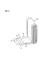
[捲回群]
図1に示すように、捲回群6は、セパレータ5を挟んで正極箔1と負極箔3とを扁平形状に捲回して構成されている。正極箔1は厚さ30μmのアルミニウムであり、負極箔3は厚さ15μmの銅である。また、セパレータ5は多孔質のポリエチレン樹脂である。正極箔1の両面には正極活物質2が塗布されており、負極箔3の両面には負極活物質4が塗布されている。捲回群6の正極活物質2と負極活物質4との間で電力を充放電する。
[Turn-up group]
As shown in FIG. 1, the
[蓋・端子組立体]
図2〜図12を参照して蓋・端子組立体200について詳細に説明する。
とくに図12に示すように、蓋・端子組立体200は、蓋11と、正負極集電板14、31と、正負極接続端子15、16と、ガスケット10と、絶縁部材12と、正負極外部端子13、32とを備え、後述する工程で一体化されている。正負極集電板14、31は、捲回群6の軸方向両端部の側面形状に沿って折曲された金属板であり、正負極箔1、3の材質と同じ、アルミニウム、銅よりなる。
[Lid and terminal assembly]
The lid /
In particular, as shown in FIG. 12, the lid /
以下、正極側の構成について説明する。
図4、5に示されるように、正極集電板14と正極接続端子15は予め溶接部20にて一体化されている。蓋11には、正極接続端子15を挿通する貫通孔11aが穿設されている。正極接続端子15は、貫通孔11aに挿入されて蓋11の外側に突出する軸部15aと、軸部よりも大径の頭部15fとを有する。正極接続端子15は、軸部15aにガスケット10を嵌装した状態で貫通孔11aに挿入され、蓋・端子組立体200が製作された後、ガスケット10は頭部15fによって蓋11の内面に圧接される。すなわち、ガスケット10には貫通孔10aが穿設され、正極接続端子15の軸部15aは貫通孔10aに挿入され、蓋11の下面側から軸部15aが蓋11の貫通孔11aを貫通している。貫通後は、ガスケット10に頭部15fが圧接され、正極接続端子15と蓋11の隙間がシールされる。
Hereinafter, the configuration on the positive electrode side will be described.
As shown in FIGS. 4 and 5, the positive electrode
図4、5に示されるように、正極接続端子15の軸部15aには、蓋11の外側で、絶縁部材12を介して正負極外部端子13が嵌装され、その後、軸部15aには、かしめ工程および溶接工程が施される。これによって、正極接続端子15の軸部15aは、蓋11に対して電気的に絶縁されつつ、正極外部端子13に電気的に接続される。
As shown in FIGS. 4 and 5, the
[かしめ工程]
蓋・端子組立体200の3段階のかしめ工程を、正極側を例にとり、詳述する。
[Caulking process]
The three-step caulking process of the lid /
[1回目のかしめ工程]
図5に示すように、軸部15aの先端部は筒状部15bとされ、先端に向かって開口する有底穴15gが形成されている。
図6に示すように、3段階のうちの1回目のかしめ工程では、平面的な金型21で頭部15fが支持された状態で、有底穴15gに先端円錐形状の金型22が圧入される。これにより、筒状部15bが押し拡げられる。こうして、正極集電板14、ガスケット10、正極外部端子13、絶縁部材12が蓋11に対して仮止めされる。
[First caulking process]
As shown in FIG. 5, the tip portion of the
As shown in FIG. 6, in the first caulking process among the three stages, the tip-shaped
[2回目のかしめ工程]
図7に示すように、2回目のかしめ工程では、平面的な金型23で頭部15fが支持された状態で、筒状部15bに、先端に環状溝24aが形成された金型24が押圧される。このとき、環状溝24a内で筒状部15bが略円盤状に押し拡げられ、拡径されることによって、略円盤状のかしめ部15dが形成される。これによって、正極集電板14、ガスケット10、正極外部端子13、絶縁部材12が蓋11に対して締め付け固定され、一体化される。
[Second caulking process]
As shown in FIG. 7, in the second caulking step, the
[3回目のかしめ工程]
図8に示すように、3回目のかしめ工程では、平面的な金型25で頭部15fが支持された状態で、かしめ部15dの周縁に、金型24を圧接する。金型24は、先端に複数(例えば、円周方向に均等に4個)の円形の突起部26aが形成されており、かしめ部15dの周縁部に、突起部26aによる円形の圧痕(薄肉平坦部)15eが等間隔に4つ形成される。
[The third caulking process]
As shown in FIG. 8, in the third caulking step, the
図9に示すように、薄肉平坦部15eは、レーザスポット溶接によって必要充分な強度で軸部15aが正極外部端子13に固着されるように、最小限の面積、個数に設定される。したがって、薄肉平坦部15eは局所的、間欠的に形成される。薄肉平坦部15eは、かしめ部15dの周縁部全周には形成されないので、薄肉になっていない部分が残り、かしめ部15d全体としてのかしめ強度は高い。
As shown in FIG. 9, the thin
車載用のリチウム二次電池では、使用中に振動荷重および衝撃荷重が電池に作用する。特に、組電池を構成した際に、正極外部端子13は隣の単電池とバスバーにより接続されるため、正極外部端子13のかしめ部15dには大きな荷重が作用する。本実施形態は、かしめ部15dの強度を高めることにより、このような荷重に耐え得る組電池を構成することができる。
In a vehicle-mounted lithium secondary battery, vibration load and impact load act on the battery during use. In particular, when the assembled battery is configured, since the positive electrode
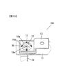
[溶接工程]
3段階のかしめ工程を経た蓋・端子組立体200は、まず、正極側の溶接を行う。
図10、図11に示すように、レーザ溶接により、正極接続端子15と正極外部端子13とが電気的に接続され、薄肉平坦部15eに溶接部30が形成される。前述のとおり、かしめ部15dは充分なかしめ強度を有するので、溶接で溶着強度に配慮する必要はない。
[Welding process]
The lid /
As shown in FIGS. 10 and 11, the positive
レーザ溶接は、複数箇所(4カ所)の薄肉平坦部15eにレーザを照射し、薄肉平坦部15eと正極外部端子13とを溶接する。なお、溶接箇所である薄肉平坦部15eの数量、溶接面積などは二次電池の充放電時の電気的特性に基づき決定される。薄肉平坦部15eが多ければ、薄肉平坦部15eと正極外部端子13との接続抵抗を低減することができる。レーザ溶接は、例えば、YAGレーザ溶接機を用い、20Jのパルスエネルギーでスポット溶接する。また、溶接部のみを局部的にプレスするので薄肉平端部15eと正極外部端子13との間の隙間がなくなり溶接品質が向上する効果もある。
In the laser welding, a plurality of (four) thin
正極側の正極接続端子15はアルミニウム製であるため、薄肉平坦部15eはレーザ光に対する反射率が高い。レーザ光の吸収率を高くするためには、薄肉平坦部15eに対して垂直にレーザ光を入射する必要があり、薄肉平坦部15eの傾斜を最小とし、できるだけ平坦な面とすることが望ましい。
Since the positive
溶接部30の近傍には絶縁部材12が配置されるが、絶縁部材12は樹脂製で融点が低い。このため、できるだけ少ないエネルギーで溶接を実施し、絶縁部材12の溶融を防止する必要がある。溶接エネルギーを低減するには、薄肉平坦部15eをできるだけ薄くすればよい。本実施形態では、薄肉平坦部15eの厚さを0.3mmとして、良好な結果を得た。
Although the insulating
正極側の溶接の完了後、負極側の溶接を行う。
負極側は、正極側と同様、ガスケット10、蓋11、絶縁部材12および負極外部端子32を負極接続端子16によりかしめ固定した後、レーザによるスポット溶接で、負極接続端子16と負極外部端子32とを溶接する。負極接続端子16と負極外部端子32はいずれも銅製であるため、レーザに対する反射率がアルミニウムより低く、例えば、50Jのエネルギーでスポット溶接する。
After completion of the positive electrode side welding, the negative electrode side welding is performed.
On the negative electrode side, the
[第2実施形態]
本発明による二次電池の第2実施形態を図13を参照して説明する。なお、図中、第1実施形態と同一もしくは相当部分には同一符号を付し、相違点を主に説明する。
第2実施形態の二次電池は、薄肉平坦部の個数を第1実施形態の二次電池よりも少数の3個としたものである。
[Second Embodiment]
A second embodiment of the secondary battery according to the present invention will be described with reference to FIG. In the figure, the same or corresponding parts as those in the first embodiment are designated by the same reference numerals, and the differences will be mainly described.
In the secondary battery of the second embodiment, the number of thin flat portions is three, which is a smaller number than the secondary battery of the first embodiment.
図13に示すように、第1実施形態の正極接続端子15と同様に、正極接続端子17の軸部17aに対して、第1実施形態の1回目、2回目のかしめ工程と同様のかしめ工程を実施する。
3回目のかしめ工程では、軸部17aに形成されたかしめ部17dに対して、3個の薄肉平坦部17eを形成し、さらに、第1実施形態と同様の溶接工程によって、薄肉平坦部17eに溶接部30を形成する。
As shown in FIG. 13, like the positive
In the third caulking step, three thin
溶接部30は、かしめ部17dの円周角180度の範囲に、円周角90度ごとに配列され、溶接部30の配列範囲は、正極外部端子13における貫通孔13bに対向している。上述したように、貫通孔13bにはバスバーが接続される。捲回群6が電力を充放電する場合に、電流は正極接続端子15と正極集電板14を通るが、このとき、溶接部30から貫通孔13bに向かう電流パスCFが形成される。この電流パスCFは、3つの溶接部30を、かしめ部17dにおける貫通孔13bに対向する側に配列することによって、最短となり、接続抵抗が低減される。
The welded
なお、溶接部30の範囲を、より狭い円周角の範囲として、すべての溶接部30を、貫通孔13bにより近接させれば、電気抵抗はさらに低減される。但し、かしめ部17dの配置の偏りが大きくなり、かしめ強度に関して不利となる可能性がある。
In addition, if the range of the
本実施形態は、第1実施形態の効果に加え、溶接工程の製造コストを低減し得るという効果を奏する。 In addition to the effects of the first embodiment, this embodiment has an effect that the manufacturing cost of the welding process can be reduced.
[第3実施形態]
本発明による二次電池の第3実施形態を図14を参照して説明する。なお、図中、第1、第2実施形態と同一もしくは相当部分には同一符号を付し、相違点を主に説明する。
第3実施形態は、薄肉平坦部の個数を第1実施形態よりも少数の1個としたものである。
[Third Embodiment]
A third embodiment of the secondary battery according to the present invention will be described with reference to FIG. In the figure, the same or corresponding parts as those in the first and second embodiments are denoted by the same reference numerals, and differences will be mainly described.
In the third embodiment, the number of thin flat portions is one, which is a smaller number than in the first embodiment.
図13に示すように、第1実施形態の正極接続端子15と同様の、正極接続端子17の軸部17aに対して、第1実施形態の1回目、2回目のかしめ工程と同様のかしめ工程を実施する。
3回目のかしめ工程では、軸部17aに形成されたかしめ部17dに対して、1個の薄肉平坦部17eを形成し、さらに、第1実施形態と同様の溶接工程によって、薄肉平坦部17eに溶接部30を形成する。
As shown in FIG. 13, the same caulking process as the first caulking process of the first embodiment with respect to the
In the third caulking step, one thin
溶接部30は、かしめ部17dにおける貫通孔13bに最も近い位置に配置され、電流パスCFは最短である。本実施形態は、第1実施形態の効果に加え、最小限の溶接工程コストにより、電気抵抗を最小化するという効果が得られる。
The welded
[第4実施形態]
本発明による二次電池の第4実施形態を図15、図16を参照して説明する。なお、図中、第1、第2実施形態と同一もしくは相当部分には同一符号を付し、相違点を主に説明する。
第4実施形態は、第2実施形態と同様の溶接部配列において、薄肉平坦部の形状を楕円形としたものである。
[Fourth Embodiment]
A fourth embodiment of the secondary battery according to the present invention will be described with reference to FIGS. In the figure, the same or corresponding parts as those in the first and second embodiments are denoted by the same reference numerals, and differences will be mainly described.
In the fourth embodiment, the thin flat portion has an elliptical shape in the same welded portion arrangement as that of the second embodiment.
図15に示すように、第1実施形態の正極接続端子15と同様の、正極外部端子17の軸部17aに対して、第1実施形態の1回目、2回目のかしめ工程と同様のかしめ工程を実施する。
3回目のかしめ工程では、軸部17aに形成されたかしめ部17dに対して、3個の楕円形の薄肉平坦部17fを形成する。3回目のかしめ工程では、先端に3個の楕円形の突起部26aが形成された金型26(図8参照)を使用する。その後、第1実施形態と同様の溶接工程によって、薄肉平坦部17fに楕円形の溶接部30を形成する。
As shown in FIG. 15, the same caulking process as the first caulking process of the first embodiment with respect to the
In the third caulking step, three oval thin
溶接部30を楕円形とすることによって、溶接部30における溶接面積が増加し、電気抵抗を低減する上で有効である。
本実施形態は、第1実施形態の効果に加え、溶接工程の製造コストを低減でき、かつ電気抵抗が比較的小さいという効果を奏する。
By making the welded
In addition to the effects of the first embodiment, this embodiment has the effects that the manufacturing cost of the welding process can be reduced and the electrical resistance is relatively small.
[変形例]
第2、第3実施形態では、溶接部30の位置を、貫通孔13bに面した側、あるいは近接した位置に配置したが、他の電池との接続手段として、溶接ボルトその他の手段が採用されていた場合には、溶接部30はこの接続手段に面した側、あるいは近接した位置に配置するのがよい。
[Modification]
In the second and third embodiments, the position of the welded
以上説明した二次電池は一例であり、本発明は上記実施形態や変形例に限定されない。 The secondary battery described above is an example, and the present invention is not limited to the above-described embodiments and modifications.
1:正極箔
2:正極活物質
3:負極箔
4:負極活物質
5:セパレータ
6:捲回群
10:ガスケット
10a:貫通孔
11:蓋
11a:貫通孔
11b:注液口
12:絶縁部材
12a:貫通孔
13:正極外部端子
13a:貫通孔
13b:貫通孔
14:正極集電板
15:正極接続端子
15a:軸部
15b:筒状部
15d:かしめ部
15e:薄肉平坦部
15f:頭部
15g:有底穴
16:負極接続端子
17:正極接続端子
17a:軸部
17d:かしめ部
17f:薄肉平坦部
30:溶接部
21:金型
22:金型
23:金型
24:金型
24a:環状溝
25:金型
26:金型
26a:突起部
31:負極集電板
32:負極外部端子
32b:貫通孔
33:缶
34:注液栓
35:蓋組立体
100:二次電池
200:蓋・端子組立体
1: Positive electrode foil 2: Positive electrode active material 3: Negative electrode foil 4: Negative electrode active material 5: Separator 6: Winding group 10:
Claims (5)
開口部を有し、前記捲回群が収納される缶と、
前記缶の開口部に溶接されて、前記開口部を封止する蓋と、
前記捲回群に電気的に接続され、かつ前記蓋を貫通して、前記蓋の外側に突出する正極接続端子および負極接続端子と、
前記蓋の外側で、前記正極接続端子および前記負極接続端子に、それぞれ接続された正極外部端子および負極外部端子と、
前記正極外部端子および前記負極外部端子を前記蓋に対して電気的に絶縁する絶縁部材と、
前記正極接続端子および前記負極接続端子と、前記蓋との隙間をシールするガスケットとを備え、
前記正極接続端子および前記負極接続端子には、前記蓋の外側で拡径されたかしめ部が形成され、
前記正極外部端子および前記負極外部端子のそれぞれには、前記蓋に沿って、前記かしめ部が接続される部分と、バスバーが接続されるバスバー接続部とが並んで設けられ、
前記かしめ部の周縁部には、レーザスポット溶接可能な薄肉平坦部が局所的に形成され、
前記正極接続端子のかしめ部における前記薄肉平坦部は、前記正極外部端子のバスバー接続部の対向側にのみ形成され、
前記負極接続端子のかしめ部における前記薄肉平坦部は、前記負極外部端子のバスバー接続部の対向側にのみ形成され、
前記薄肉平坦部がレーザスポット溶接されていることを特徴とする二次電池。 A winding group for charging and discharging power;
A can having an opening and storing the wound group;
A lid welded to the opening of the can to seal the opening;
A positive connection terminal and a negative connection terminal that are electrically connected to the winding group and penetrate the cover and project outside the cover;
Outside the lid, a positive external terminal and a negative external terminal connected to the positive connection terminal and the negative connection terminal, respectively,
An insulating member that electrically insulates the positive electrode external terminal and the negative electrode external terminal from the lid;
The positive electrode connecting terminal and the negative electrode connecting terminal, and a gasket that seals a gap between the lid,
The positive electrode connection terminal and the negative electrode connection terminal are formed with a caulked portion whose diameter is increased outside the lid,
Each of the positive external terminal and the negative external terminal is provided with a portion along which the caulking portion is connected and a bus bar connecting portion to which a bus bar is connected, along the lid.
A thin flat portion capable of laser spot welding is locally formed on the peripheral edge of the caulking portion,
The thin flat portion in the caulking portion of the positive electrode connection terminal is formed only on the opposite side of the bus bar connection portion of the positive electrode external terminal,
The thin flat portion in the caulking portion of the negative electrode connection terminal is formed only on the opposite side of the bus bar connection portion of the negative electrode external terminal,
A secondary battery, wherein the thin flat portion is laser spot welded.
前記薄肉平坦部は、前記かしめ部の最外周よりも内側に形成されていることを特徴とする二次電池。 The secondary battery according to claim 1,
The secondary battery according to claim 1, wherein the thin flat portion is formed on an inner side of an outermost periphery of the caulking portion .
前記正極接続端子のかしめ部には、少なくとも前記正極外部端子のバスバー接続部に最も近い位置に前記薄肉平坦部が配置され、
前記負極接続端子のかしめ部には、少なくとも前記負極外部端子のバスバー接続部に最も近い位置に前記薄肉平坦部が配置されていることを特徴とする二次電池。 The secondary battery according to claim 1 or 2,
In the caulking portion of the positive electrode connecting terminal, the thin flat portion is arranged at a position closest to the bus bar connecting portion of the positive electrode external terminal,
The secondary battery is characterized in that the thin flat portion is disposed at a position closest to the bus bar connecting portion of the negative external terminal at the caulking portion of the negative connecting terminal .
前記正極接続端子および前記負極接続端子のかしめ部のそれぞれには、前記薄肉平坦部が複数形成されていることを特徴とする二次電池。 The secondary battery according to any one of claims 1 to 3 ,
A secondary battery in which a plurality of the thin flat portions are formed in each of the caulking portions of the positive electrode connecting terminal and the negative electrode connecting terminal .
前記薄肉平坦部は円形または楕円形であることを特徴とする二次電池。 The secondary battery according to any one of claims 1 to 4 ,
The secondary battery according to claim 1, wherein the thin flat portion is circular or elliptical .
Priority Applications (2)
| Application Number | Priority Date | Filing Date | Title |
|---|---|---|---|
| JP2010167995A JP5590391B2 (en) | 2010-07-27 | 2010-07-27 | Secondary battery |
| PCT/JP2011/053971 WO2012014510A1 (en) | 2010-07-27 | 2011-02-23 | Secondary cell |
Applications Claiming Priority (1)
| Application Number | Priority Date | Filing Date | Title |
|---|---|---|---|
| JP2010167995A JP5590391B2 (en) | 2010-07-27 | 2010-07-27 | Secondary battery |
Publications (3)
| Publication Number | Publication Date |
|---|---|
| JP2012028246A JP2012028246A (en) | 2012-02-09 |
| JP2012028246A5 JP2012028246A5 (en) | 2012-08-23 |
| JP5590391B2 true JP5590391B2 (en) | 2014-09-17 |
Family
ID=45529734
Family Applications (1)
| Application Number | Title | Priority Date | Filing Date |
|---|---|---|---|
| JP2010167995A Expired - Fee Related JP5590391B2 (en) | 2010-07-27 | 2010-07-27 | Secondary battery |
Country Status (2)
| Country | Link |
|---|---|
| JP (1) | JP5590391B2 (en) |
| WO (1) | WO2012014510A1 (en) |
Cited By (1)
| Publication number | Priority date | Publication date | Assignee | Title |
|---|---|---|---|---|
| EP4012833A1 (en) | 2020-12-11 | 2022-06-15 | Prime Planet Energy & Solutions, Inc. | Sealed battery and method of manufacturing sealed battery |
Families Citing this family (23)
| Publication number | Priority date | Publication date | Assignee | Title |
|---|---|---|---|---|
| JP5626181B2 (en) * | 2011-11-10 | 2014-11-19 | トヨタ自動車株式会社 | Sealed battery and method for manufacturing the same |
| JP6225421B2 (en) * | 2012-01-27 | 2017-11-08 | 株式会社Gsユアサ | Power storage device and method for manufacturing power storage device |
| JP5976340B2 (en) * | 2012-02-29 | 2016-08-23 | 三洋電機株式会社 | Method for manufacturing prismatic secondary battery |
| JP5668729B2 (en) | 2012-06-25 | 2015-02-12 | トヨタ自動車株式会社 | battery |
| JP5894118B2 (en) | 2012-06-25 | 2016-03-23 | トヨタ自動車株式会社 | battery |
| JP5692173B2 (en) * | 2012-06-27 | 2015-04-01 | トヨタ自動車株式会社 | battery |
| JP2014010992A (en) * | 2012-06-28 | 2014-01-20 | Toyota Motor Corp | Sealed battery and manufacturing method therefor |
| JP5637181B2 (en) | 2012-06-29 | 2014-12-10 | トヨタ自動車株式会社 | Battery, battery manufacturing method, and battery manufacturing mask member |
| CN104412413B (en) * | 2012-06-29 | 2017-05-10 | 丰田自动车株式会社 | Battery |
| JP2014017081A (en) * | 2012-07-06 | 2014-01-30 | Hitachi Vehicle Energy Ltd | Secondary battery |
| JP5682617B2 (en) | 2012-12-25 | 2015-03-11 | トヨタ自動車株式会社 | Sealed battery |
| WO2015025388A1 (en) | 2013-08-22 | 2015-02-26 | 日立オートモティブシステムズ株式会社 | Secondary cell |
| JP6428123B2 (en) | 2014-10-06 | 2018-11-28 | 株式会社Gsユアサ | Electricity storage element |
| US10269502B2 (en) | 2015-08-25 | 2019-04-23 | Gs Yuasa International Ltd. | Energy storage device including a conductive member penetrating a container and a fixing member covering the conductive member |
| JP6573110B2 (en) * | 2015-10-05 | 2019-09-11 | トヨタ自動車株式会社 | Battery manufacturing method |
| JP6911771B2 (en) | 2016-02-09 | 2021-07-28 | 株式会社Gsユアサ | Manufacturing method of power storage element and power storage element |
| JP6796260B2 (en) * | 2017-08-23 | 2020-12-09 | トヨタ自動車株式会社 | Sealed battery |
| JP6970889B2 (en) * | 2017-12-28 | 2021-11-24 | トヨタ自動車株式会社 | Sealed battery |
| JP7245044B2 (en) * | 2018-12-25 | 2023-03-23 | 本田技研工業株式会社 | Solid-state battery cell structure and solid-state battery manufacturing method |
| CN113725559A (en) * | 2020-05-21 | 2021-11-30 | 东莞新能德科技有限公司 | Battery and method for assembling battery |
| JP7218330B2 (en) | 2020-08-06 | 2023-02-06 | プライムアースEvエナジー株式会社 | assembled battery |
| JP7321984B2 (en) * | 2020-09-03 | 2023-08-07 | プライムアースEvエナジー株式会社 | secondary battery |
| CN114069121A (en) * | 2021-11-11 | 2022-02-18 | 新余赣锋电子有限公司 | Pre-compaction battery face lid and button cell |
Family Cites Families (6)
| Publication number | Priority date | Publication date | Assignee | Title |
|---|---|---|---|---|
| JP4304919B2 (en) * | 2002-06-04 | 2009-07-29 | 株式会社ジーエス・ユアサコーポレーション | battery |
| JP5213404B2 (en) * | 2007-09-28 | 2013-06-19 | 三洋電機株式会社 | Sealed battery and manufacturing method thereof |
| JP2009110885A (en) * | 2007-10-31 | 2009-05-21 | Sanyo Electric Co Ltd | Sealed battery and its manufacturing method |
| JP2009283256A (en) * | 2008-05-21 | 2009-12-03 | Toyota Motor Corp | Power supply device and power supply device manufacturing method |
| JP5168007B2 (en) * | 2008-07-25 | 2013-03-21 | トヨタ自動車株式会社 | Battery, vehicle, battery-mounted device, and battery manufacturing method |
| JP5232840B2 (en) * | 2010-09-03 | 2013-07-10 | 日立ビークルエナジー株式会社 | Secondary battery and manufacturing method thereof |
-
2010
- 2010-07-27 JP JP2010167995A patent/JP5590391B2/en not_active Expired - Fee Related
-
2011
- 2011-02-23 WO PCT/JP2011/053971 patent/WO2012014510A1/en active Application Filing
Cited By (1)
| Publication number | Priority date | Publication date | Assignee | Title |
|---|---|---|---|---|
| EP4012833A1 (en) | 2020-12-11 | 2022-06-15 | Prime Planet Energy & Solutions, Inc. | Sealed battery and method of manufacturing sealed battery |
Also Published As
| Publication number | Publication date |
|---|---|
| WO2012014510A1 (en) | 2012-02-02 |
| JP2012028246A (en) | 2012-02-09 |
Similar Documents
| Publication | Publication Date | Title |
|---|---|---|
| JP5590391B2 (en) | Secondary battery | |
| JP6806217B2 (en) | Rechargeable battery | |
| JP6093874B2 (en) | Prismatic secondary battery | |
| JP6089784B2 (en) | Prismatic secondary battery | |
| JP5558569B2 (en) | Battery and battery pack | |
| US7700231B2 (en) | Battery and battery assembly | |
| JP6569322B2 (en) | Secondary battery and assembled battery using the same | |
| US8936861B2 (en) | Sealed battery | |
| JP6208687B2 (en) | Cylindrical secondary battery and manufacturing method thereof | |
| JP5856858B2 (en) | Method for manufacturing prismatic secondary battery | |
| KR20110035868A (en) | Secondary cell | |
| JP2016207510A (en) | Square secondary battery | |
| JP2020107464A (en) | Secondary battery and battery pack | |
| CN107665968B (en) | Secondary battery, method for manufacturing same, and assembled battery using same | |
| JPWO2012169055A1 (en) | Secondary battery | |
| JP2016225014A (en) | Cylindrical secondary battery | |
| JP2020035694A (en) | Secondary battery | |
| US7776469B2 (en) | Secondary battery having a current collecting plate with improved welding characteristics | |
| JP2020205269A (en) | Wound battery | |
| CN109585770B (en) | Secondary battery and method for manufacturing same | |
| CN108232280B (en) | Prismatic secondary battery and method for manufacturing same | |
| JP6878878B2 (en) | Rechargeable battery manufacturing method and rechargeable battery | |
| JP2017183619A (en) | Power storage device | |
| JP6156728B2 (en) | Power storage element and power storage device | |
| JP2016110772A (en) | Cylindrical secondary battery |
Legal Events
| Date | Code | Title | Description |
|---|---|---|---|
| A521 | Request for written amendment filed |
Free format text: JAPANESE INTERMEDIATE CODE: A523 Effective date: 20120705 |
|
| A621 | Written request for application examination |
Free format text: JAPANESE INTERMEDIATE CODE: A621 Effective date: 20120705 |
|
| A131 | Notification of reasons for refusal |
Free format text: JAPANESE INTERMEDIATE CODE: A131 Effective date: 20131119 |
|
| A521 | Request for written amendment filed |
Free format text: JAPANESE INTERMEDIATE CODE: A523 Effective date: 20140120 |
|
| TRDD | Decision of grant or rejection written | ||
| A01 | Written decision to grant a patent or to grant a registration (utility model) |
Free format text: JAPANESE INTERMEDIATE CODE: A01 Effective date: 20140617 |
|
| A711 | Notification of change in applicant |
Free format text: JAPANESE INTERMEDIATE CODE: A712 Effective date: 20140711 |
|
| A61 | First payment of annual fees (during grant procedure) |
Free format text: JAPANESE INTERMEDIATE CODE: A61 Effective date: 20140716 |
|
| R150 | Certificate of patent or registration of utility model |
Ref document number: 5590391 Country of ref document: JP Free format text: JAPANESE INTERMEDIATE CODE: R150 |
|
| R250 | Receipt of annual fees |
Free format text: JAPANESE INTERMEDIATE CODE: R250 |
|
| LAPS | Cancellation because of no payment of annual fees |