KR20110035854A - Conducting block for resistance welding, manufacturing method of sealed battery using the conducting block and sealed battery - Google Patents
Conducting block for resistance welding, manufacturing method of sealed battery using the conducting block and sealed battery Download PDFInfo
- Publication number
- KR20110035854A KR20110035854A KR1020100081288A KR20100081288A KR20110035854A KR 20110035854 A KR20110035854 A KR 20110035854A KR 1020100081288 A KR1020100081288 A KR 1020100081288A KR 20100081288 A KR20100081288 A KR 20100081288A KR 20110035854 A KR20110035854 A KR 20110035854A
- Authority
- KR
- South Korea
- Prior art keywords
- block
- resistance welding
- positive electrode
- core exposed
- sealed battery
- Prior art date
Links
Images


Classifications
-
- H—ELECTRICITY
- H01—ELECTRIC ELEMENTS
- H01M—PROCESSES OR MEANS, e.g. BATTERIES, FOR THE DIRECT CONVERSION OF CHEMICAL ENERGY INTO ELECTRICAL ENERGY
- H01M10/00—Secondary cells; Manufacture thereof
- H01M10/05—Accumulators with non-aqueous electrolyte
-
- B—PERFORMING OPERATIONS; TRANSPORTING
- B23—MACHINE TOOLS; METAL-WORKING NOT OTHERWISE PROVIDED FOR
- B23K—SOLDERING OR UNSOLDERING; WELDING; CLADDING OR PLATING BY SOLDERING OR WELDING; CUTTING BY APPLYING HEAT LOCALLY, e.g. FLAME CUTTING; WORKING BY LASER BEAM
- B23K11/00—Resistance welding; Severing by resistance heating
- B23K11/10—Spot welding; Stitch welding
- B23K11/11—Spot welding
-
- H—ELECTRICITY
- H01—ELECTRIC ELEMENTS
- H01M—PROCESSES OR MEANS, e.g. BATTERIES, FOR THE DIRECT CONVERSION OF CHEMICAL ENERGY INTO ELECTRICAL ENERGY
- H01M10/00—Secondary cells; Manufacture thereof
- H01M10/05—Accumulators with non-aqueous electrolyte
- H01M10/058—Construction or manufacture
- H01M10/0587—Construction or manufacture of accumulators having only wound construction elements, i.e. wound positive electrodes, wound negative electrodes and wound separators
-
- H—ELECTRICITY
- H01—ELECTRIC ELEMENTS
- H01M—PROCESSES OR MEANS, e.g. BATTERIES, FOR THE DIRECT CONVERSION OF CHEMICAL ENERGY INTO ELECTRICAL ENERGY
- H01M50/00—Constructional details or processes of manufacture of the non-active parts of electrochemical cells other than fuel cells, e.g. hybrid cells
- H01M50/50—Current conducting connections for cells or batteries
- H01M50/528—Fixed electrical connections, i.e. not intended for disconnection
-
- Y—GENERAL TAGGING OF NEW TECHNOLOGICAL DEVELOPMENTS; GENERAL TAGGING OF CROSS-SECTIONAL TECHNOLOGIES SPANNING OVER SEVERAL SECTIONS OF THE IPC; TECHNICAL SUBJECTS COVERED BY FORMER USPC CROSS-REFERENCE ART COLLECTIONS [XRACs] AND DIGESTS
- Y02—TECHNOLOGIES OR APPLICATIONS FOR MITIGATION OR ADAPTATION AGAINST CLIMATE CHANGE
- Y02E—REDUCTION OF GREENHOUSE GAS [GHG] EMISSIONS, RELATED TO ENERGY GENERATION, TRANSMISSION OR DISTRIBUTION
- Y02E60/00—Enabling technologies; Technologies with a potential or indirect contribution to GHG emissions mitigation
- Y02E60/10—Energy storage using batteries
-
- Y—GENERAL TAGGING OF NEW TECHNOLOGICAL DEVELOPMENTS; GENERAL TAGGING OF CROSS-SECTIONAL TECHNOLOGIES SPANNING OVER SEVERAL SECTIONS OF THE IPC; TECHNICAL SUBJECTS COVERED BY FORMER USPC CROSS-REFERENCE ART COLLECTIONS [XRACs] AND DIGESTS
- Y02—TECHNOLOGIES OR APPLICATIONS FOR MITIGATION OR ADAPTATION AGAINST CLIMATE CHANGE
- Y02P—CLIMATE CHANGE MITIGATION TECHNOLOGIES IN THE PRODUCTION OR PROCESSING OF GOODS
- Y02P70/00—Climate change mitigation technologies in the production process for final industrial or consumer products
- Y02P70/50—Manufacturing or production processes characterised by the final manufactured product
-
- Y—GENERAL TAGGING OF NEW TECHNOLOGICAL DEVELOPMENTS; GENERAL TAGGING OF CROSS-SECTIONAL TECHNOLOGIES SPANNING OVER SEVERAL SECTIONS OF THE IPC; TECHNICAL SUBJECTS COVERED BY FORMER USPC CROSS-REFERENCE ART COLLECTIONS [XRACs] AND DIGESTS
- Y10—TECHNICAL SUBJECTS COVERED BY FORMER USPC
- Y10T—TECHNICAL SUBJECTS COVERED BY FORMER US CLASSIFICATION
- Y10T29/00—Metal working
- Y10T29/49—Method of mechanical manufacture
- Y10T29/49002—Electrical device making
- Y10T29/49108—Electric battery cell making
- Y10T29/4911—Electric battery cell making including sealing
Abstract
Description
본 발명은 서로 2분할되어 있는 적층된 정극심체(正極芯體) 노출부 및 부극심체(負極芯體) 노출부를 가지는 밀폐전지에 있어서, 각각의 심체 노출부와 집전용 부재와의 사이의 저(低)저항화를 실현할 수 있고, 1회의 용접으로 하면서 안정적으로 저항용접 할 수 있는 저항용접용 통전블록, 이 통전블록을 이용한 밀폐전지의 제조방법 및 밀폐전지에 관한 것이다.The present invention relates to a sealed battery having laminated positive electrode exposed portions and negative electrode exposed portions which are divided into two parts, wherein each core exposed portion and a current collector member are separated from each other. I) Resistance resistance can be realized and the resistance welding energization block can be stably welded with one welding, and the present invention relates to a sealed battery manufacturing method and a sealed battery using the energization block.
최근, 환경보호운동이 고취되어, 이산화탄소 가스 등의 온난화의 원인이 되는 배기가스의 배출규제가 강화되고 있다. 그 때문에, 자동차 업계에서는 가솔린, 디젤유, 천연가스 등의 화석연료를 사용하는 자동차를 바꾸어, 전기자동차(EV)나 하이브리드 전기자동차(HEV)의 개발이 활발하게 행해지고 있다. 이와 같은 EV, HEV용 전지로서는 니켈-수소 2차전지나 리튬이온 2차전지가 사용되고 있지만, 최근은 경량이고 또한 고용량의 전지가 얻어진다는 것 때문에, 리튬이온 2차전지 등의 비수전해질(非水電解質) 2차전지가 많이 이용되도록 되어 있다.In recent years, the environmental protection movement has been promoted, and the restriction on the emission of exhaust gas, which causes warming of carbon dioxide gas and the like, has been tightened. For this reason, in the automobile industry, automobiles using fossil fuels such as gasoline, diesel oil and natural gas have been replaced, and development of electric vehicles (EVs) and hybrid electric vehicles (HEVs) has been actively performed. As such EV and HEV batteries, nickel-hydrogen secondary batteries and lithium ion secondary batteries are used. However, in recent years, non-aqueous electrolytes, such as lithium ion secondary batteries, have been obtained because a battery having a light weight and a high capacity can be obtained. Secondary batteries are to be used a lot.
EV, HEV 용도에서는 환경 대응뿐만이 아니라, 자동차로서의 기본성능, 즉, 가속성능이나 등판(登坂)성능 등의 주행능력의 고도화도 필요하게 된다. 이와 같은 요구를 만족하기 위해서는, 단지 전지용량을 크게 하는 것뿐만 아니라, 고출력의 전지가 필요하다. 일반적으로, EV, HEV용의 비수전해질 2차전지는 발전요소를 알루미늄계 금속제의 각형(角形) 외장캔 내에 수용한 각형 밀폐전지가 많이 사용되고 있지만, 고출력의 방전을 행하면 전지에 대전류가 흐르기 때문에, 전지의 내부저항을 최대한 저감시킬 필요가 있다. 그 때문에, 전지의 발전요소에서의 전극시트의 심체와 집전용 부재와의 사이의 용접불량을 방지하여 내부저항을 저하시키는 것에 대하여도 여러 가지의 개량이 행해져 오고 있다.In EV and HEV applications, not only the environmental response but also the advancement of the driving performance such as the basic performance as an automobile, that is, the acceleration performance and the climbing performance, is required. In order to satisfy such a demand, not only a large battery capacity but also a high output battery is required. Generally, non-aqueous electrolyte secondary batteries for EV and HEV are often used in rectangular sealed batteries in which a power generation element is contained in an aluminum metal rectangular outer can. However, when a high-output discharge causes a large current to flow in the battery, It is necessary to reduce internal resistance of maximally. For this reason, various improvements have been made in reducing the internal resistance by preventing welding defects between the core of the electrode sheet and the current collector member in the battery power generation element.
발전요소에서의 전극시트의 심체와 집전(集電)용 부재를 전기적으로 접합하여 집전하는 방법으로서는 기계적인 코킹(caulking)법, 용접법 등이 있지만, 고출력이 요구되는 전지의 집전방법으로서는 저저항화를 실현하기 쉽고, 또한 경시(經時)변화가 생기기 어렵기 때문에 용접법이 적합하다. 또, 리튬이온 2차전지에서는 저저항화를 실현하기 위해서, 정극시트의 심체 재료 및 집전용 부재의 재료로서는 알루미늄 또는 알루미늄 합금이 사용되고, 부극시트의 심체 재료 및 집전용 부재의 재료로서는 동 또는 동합금이 사용되고 있다. 그러나, 알루미늄, 알루미늄 합금, 동 및 동합금은 그 특성으로서 전기저항이 작고, 열전도율이 크기 때문에, 용접하기 위해서는 매우 큰 에너지가 필요하게 된다.As a method of electrically bonding the core of the electrode sheet and the current collecting member in the power generation element to collect current, there are mechanical caulking and welding methods, but as the current collection method of a battery requiring high output, the resistance is reduced. The welding method is suitable because it is easy to realize and hardly changes with time. In order to achieve low resistance in lithium ion secondary batteries, aluminum or aluminum alloy is used as the core material of the positive electrode sheet and the collector member, and copper or copper alloy is used as the core material of the negative electrode sheet and the collector member. Is being used. However, since aluminum, aluminum alloy, copper, and copper alloy have small electric resistance and high thermal conductivity as their characteristics, very large energy is required for welding.
이와 같은 발전요소의 전극시트의 심체와 집전용 부재와의 사이의 용접방법으로서는, 종래부터 이하의 방법이 알려져 있다.As a welding method between the core of the electrode sheet of such a power generating element and the current collector member, the following method has been known.
(1) 레이저 용접법(하기 특허문헌 1 참조)(1) laser welding method (see Patent Document 1 below)
(2) 초음파 용접법(하기 특허문헌 2 참조)(2) Ultrasonic welding (see Patent Document 2 below)
(3) 저항용접법(하기 특허문헌 3 참조)(3) Resistance welding method (see Patent Document 3 below)
레이저 용접법에서는 피용접재료인 알루미늄, 알루미늄 합금, 동 및 동합금은 금속용접용으로 널리 사용되고 있는 YAG(이트륨-알루미늄-가넷(garnet)) 레이저광에 대한 반사율이 약 90%로 높기 때문에, 고에너지의 레이저광이 필요하다. 또, 알루미늄, 알루미늄 합금, 동 및 동합금을 레이저 용접하면, 표면 상태의 영향에 의해 용접성이 크게 변하는 것, 및, 다른 재질의 레이저 용접의 경우와 마찬가지로, 스퍼터(sputter)의 발생이 불가피하다는 문제점이 존재한다.In the laser welding method, aluminum, aluminum alloy, copper, and copper alloy to be welded have high reflectivity of about 90% for YAG (yttrium-aluminum-garnet) laser light, which is widely used for metal welding. Laser light is necessary. In addition, when laser welding aluminum, aluminum alloy, copper and copper alloy, the weldability is greatly changed by the influence of the surface state, and as in the case of laser welding of other materials, there is a problem that sputtering is inevitable. exist.
초음파 용접에서도 피용접재료인 알루미늄, 알루미늄 합금, 동 및 동합금의 열전도율이 크기 때문에, 큰 에너지가 필요하며, 또, 용접시의 초음파 진동에 의해서 정극 활물질(活物質) 및 부극 활물질의 탈락이 생긴다. 그 때문에, 하기 특허문헌 2에 개시되어 있는 발명에서는 초음파 용접시에 발전요소인 전극체를 압축하여 탈락한 활물질이 전극체 내에 침입하지 않도록 하고 있다.In ultrasonic welding, the thermal conductivity of aluminum, aluminum alloy, copper, and copper alloy, which are the materials to be welded, is large, so that a large amount of energy is required, and the positive electrode active material and the negative electrode active material fall off by ultrasonic vibration during welding. Therefore, in the invention disclosed in Patent Document 2 below, the active material that is compressed by the electrode body as a power generating element during the ultrasonic welding is eliminated so as not to enter the electrode body.
또한, 저항용접에서는 피용접재료인 알루미늄, 알루미늄 합금, 동 및 동합금의 전기저항이 작은 것 및 열전도율이 큰 것으로부터 단시간에 대전류의 투입이 필요한 것, 저항용접시에 저항용접용 전극봉과 집전용 부재와의 융접이 발생하는 일이 있는 것, 용접부 이외에서의 융해(融解)나 스파크의 발생이 생긴다고 하는 문제점이 존재하고 있다.In the case of resistance welding, the electrical resistance of aluminum, aluminum alloy, copper and copper alloy as the material to be welded is small, and the thermal conductivity is large, requiring a large current to be input in a short time, and the electrode and current collector for resistance welding during resistance welding. There exists a problem that fusion with and arising may arise, and melt | dissolution and a spark generate | occur | produce other than a weld part.
상술한 바와 같이 3종류의 용접방법에는 일장일단이 있지만, 생산성 및 경제성을 고려하면, 종래부터 금속간의 용접법으로서 널리 사용되고 있는 저항용접법을 채용하는 것이 바람직하다. 그렇지만, EV, HEV용의 리튬이온 2차전지 등의 전극체는 정극시트와 부극시트가 세퍼레이터를 통하여 감아돌림 내지 적층된 구성을 구비하고 있다. 그리고, 정극시트 또는 부극시트의 심체 노출부는 각각 서로 다른 측에 위치하도록 배치되며, 정극시트의 심체 노출부는 적층되어 정극집전용 부재에 용접되며, 부극시트의 심체 노출부도 적층되어 부극집전용 부재에 용접되어 있다. 이들 정극심체 노출부 및 부극심체 노출부의 적층 매수는 EV, HEV용의 리튬이온 2차전지 등의 용량이 큰 경우에는 매우 많아진다.As described above, the three types of welding methods are one-off. However, in consideration of productivity and economic efficiency, it is preferable to adopt a resistance welding method which is conventionally widely used as a welding method between metals. However, an electrode body such as a lithium ion secondary battery for EV and HEV has a structure in which a positive electrode sheet and a negative electrode sheet are wound or laminated through a separator. The core exposed portions of the positive electrode sheet or the negative electrode sheet are disposed on different sides, respectively, and the core exposed portions of the positive electrode sheet are laminated and welded to the positive electrode collector member, and the core exposed portions of the negative electrode sheet are also laminated to the negative electrode collector member. Welded The number of stacked sheets of the positive electrode core exposed portion and the negative electrode core exposed portion becomes very large when the capacity of a lithium ion secondary battery for EV and HEV is large.
그 때문에, 정극시트의 심체 노출부에 대해서 알루미늄 또는 알루미늄 합금제의 집전용 부재를, 또, 부극시트의 심체 노출부에 대해서 동 또는 동합금제의 집전용 부재를 각각 확실히 저항용접하려면 다대(多大)한 용접에너지를 필요로 한다. 게다가, 저항용접할 때, 용접에너지를 크게 하면, 스퍼터에 의한 먼지 입자의 발생이 증가하고, 이 먼지 입자가 전극체 내부로 이동하는 것에 의해서 내부 단락의 원인이 될 가능성이 증가한다.Therefore, in order to reliably weld resistance collectors made of aluminum or aluminum alloy to the core exposed portions of the positive electrode sheet, and the current collector members made of copper or copper alloy with respect to the core exposed portions of the negative electrode sheets, many It requires one welding energy. In addition, in the case of resistance welding, when the welding energy is increased, the generation of dust particles by the sputter increases, and the possibility of causing an internal short circuit increases by moving the dust particles inside the electrode body.
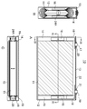
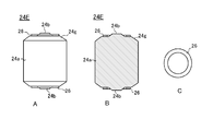
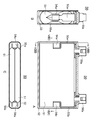
한편, 하기 특허문헌 4에는 정극시트 및 부극시트가 세퍼레이터를 통하여 편평 모양으로 감겨진 전극체에서 세퍼레이터로부터 불거져 나와 있는 각각의 전극의 심체 노출부의 폭을 작게 하기 위해서, 각각의 전극의 심체 노출부를 2개소씩으로 나누어 집전용 부재에 용접한 축전(蓄電)소자의 발명이 개시되어 있다. 여기에서 하기 특허문헌 4에 개시되어 있는 축전소자의 구성을 도 8 및 도 9를 이용하여 설명한다. 또한, 도 8의 A는 하기 특허문헌 4에 개시되어 있는 축전소자로서의 전기 이중층 캐패시터의 단면도 이고, 도 8의 B는 도 8의 A의 VIIIB-VIIIB선에 따른 단면도이며, 도 8의 C는 도 8의 A의 VIIIC-VIIIC선에 따른 단면도이다. 또, 도 9는 도 8에서의 전극의 심체 노출부와 집전용 부재와의 사이의 용접공정도를 나타내는 도면이다.On the other hand, Patent Document 4 discloses a core exposed portion of each electrode in order to reduce the width of the core exposed portion of each electrode that is blown out of the separator in the electrode body in which the positive electrode sheet and the negative electrode sheet are wound in a flat shape through the separator. Disclosed is a power storage element welded to a current collector member divided into parts. Here, the structure of the electrical storage element disclosed by following patent document 4 is demonstrated using FIG. 8 and FIG. 8A is a cross-sectional view of an electric double layer capacitor as a power storage element disclosed in Patent Document 4 below, FIG. 8B is a cross-sectional view taken along the line VIIIB-VIIIB of FIG. 8A, and FIG. It is sectional drawing along the VIIIC-VIIIC line | wire of A of 8. 9 is a diagram showing a welding process diagram between the core exposed portion of the electrode and the current collector member in FIG. 8.
이 축전소자(50)는, 도 8의 A ~ 도 8의 C에 나타낸 바와 같이, 정극시트 및 부극시트가 세퍼레이터(모두 도시생략)를 통하여 편평 모양으로 감겨진 권회(卷回)전극체(51)를 구비하고 있고, 이 권회전극체(51)는 각형의 알루미늄제의 외장캔(52) 내에 배치되어 있다. 또, 이 축전소자(50)의 정극용 집전부재(53a) 및 부극용 집전부재(53b)는 각각 한쪽의 단부에 'コ'자형의 날개부(54a 내지 54b)가 형성되고, 각각 정극시트의 심체 노출부(55a) 내지 부극시트의 심체 노출부(55b)에 접속되며, 다른 쪽의 단부는 각각 정극단자(56a) 내지 부극단자(56b)에 접속되어 있다. 그리고, 정극시트의 심체 노출부(55a)는 묶여져 2분할되고, 각각 한쪽의 'コ'자형의 날개부(54a)의 외면 측의 2개소에 용접되어 있으며, 또, 부극시트의 심체 노출부(55b)도 2분할되어 각각 다른 쪽의 'コ'자형의 날개부(54b)의 외면 측의 2개소에 용접되어 있다.In this
이 용접은, 예를 들면 정극시트 측이면, 도 9에 나타낸 바와 같이, 2분할된 정극시트의 심체 노출부(55a) 중 한쪽을 'コ'자형의 날개부(54a)의 외면에 배치하고, 이 심체 노출부(55a)의 외표면에 초음파 용접장치(도시생략)의 혼(57)을 맞닿게 하여, 'コ'자형의 날개부(54a)의 내면 측에 앤빌(anvil)(58)을 배치함으로써, 초음파 용접이 행해지고 있다. 또한, 2분할된 정극시트의 심체 노출부(55a)의 다른 쪽에 대해서도 동일한 방법으로 초음파 용접이 행해지고 있으며, 또, 부극시트 측에서도 마찬가지이다.As for this welding, if it is a positive electrode sheet side, as shown in FIG. 9, one of the core exposed
상기 특허문헌 4에 개시되어 있는 발명에 의하면, 정극심체 노출부 및 부극심체 노출부의 노출폭을 작게 할 수 있기 때문에, 축전장치의 용적효율이 양호하게 된다고 하는 효과를 발휘한다. 그렇지만, 본 발명에서는 정극시트 내지 부극시트에 정극용 집전부재 내지 부극용 집전부재를 용접하기 위해서는 각각 복수 회의 용접이 필요하고, 또한, 권회전극체의 중앙부에는 용접하기 위한 정극용 집전부재 내지 부극용 집전부재의 'コ'자형의 날개부를 배치하기 위한 개구공간을 필요로 하는 것, 초음파 용접시에 'コ'자형의 날개부의 내부에 앤빌을 배치할 필요가 있는 것 등, 제조설비가 복잡화 한다고 하는 문제점이 존재하고 있다.According to the invention disclosed in Patent Document 4, since the exposure width of the positive electrode core exposed portion and the negative electrode core exposed portion can be reduced, the volumetric efficiency of the power storage device can be improved. However, in the present invention, in order to weld the positive electrode current collector member or the negative electrode current collector member to the positive electrode sheet or the negative electrode sheet, a plurality of weldings are required, respectively, and the positive electrode current collector member for the negative electrode for welding to the center portion of the wound electrode body. The manufacturing facilities are complicated by requiring an opening space for arranging the 'co' wings of the current collecting member, and the need to arrange an anvil inside the 'co' wings during ultrasonic welding. There is a problem.
또, 상기 특허문헌 4에는 전극시트를 접속하는 공정은 초음파 용접법을 이용하는 것이 특히 바람직하다고 기재되어 있지만, 실시예에서의 권회수는 16회(2분할한 한쪽 편에서는 8회)이며, 적층두께는 320㎛로 되어 있다. 그에 대해, EV, HEV용의 리튬이온 2차전지 등의 용량이 큰 밀폐전지에서는 정극심체 노출부 및 부극심체 노출부의 적층 매수는 상기 특허문헌 4에 개시되어 있는 발명의 경우보다 매우 많게 되어 있음과 아울러, 적층두께도 상당히 두꺼워져 있다.In addition, although the process of connecting an electrode sheet is described in the said patent document 4 using an ultrasonic welding method, it is especially preferable, The number of turns in an Example is 16 times (8 times on one side divided into two), and the lamination thickness is It is 320 micrometers. On the other hand, in a sealed battery having a large capacity such as a lithium ion secondary battery for EV and HEV, the number of stacks of the positive electrode core exposed portion and the negative electrode core exposed portion is much larger than that of the invention disclosed in Patent Document 4 above. In addition, the lamination thickness is also considerably thicker.
그 때문에, EV, HEV용의 리튬이온 2차전지 등의 용량이 큰 밀폐전지에서는 적층된 정극심체 노출부 및 부극심체 노출부와 집전용 부재와의 사이의 용접방법으로서, 초음파 용접법을 채용하여 안정되어 용접하기 위해서는 적층된 정극심체 노출부 및 부극심체 노출부를 각각 집전용 부재에 밀착시키기 위한 큰 가압과, 초음파 진동을 적층된 정극심체 노출부 및 부극심체 노출부의 타단 측까지 도달시키기 위한 큰 에너지가 필요하다. 상기 특허문헌 4에 개시되어 있는 발명에서는 'コ'자형의 집전용 부재의 내부에 배치된 앤빌에서 가압 및 초음파 에너지를 받을 필요가 있기 때문에, 앤빌에 상응하는 강성이 필요하고, 게다가, 'コ'자형의 집전용 부재의 내부에 공급할 수 있는 크기의 앤빌에서 큰 가압을 받으면서 더욱 안정된 용접 조건을 찾아내는 것은 기술적으로 매우 곤란하다.Therefore, in a sealed battery having a large capacity such as a lithium ion secondary battery for EV and HEV, ultrasonic welding is adopted as a welding method between the stacked positive electrode core exposed portion and negative electrode core exposed portion and the current collector member. In order to be welded, a large press for closely contacting the stacked core core exposed portion and the negative core core exposed portion to the current collector member and a large energy for reaching ultrasonic vibration to the other end side of the stacked core core exposed portion and the negative core core exposed portion need. In the invention disclosed in Patent Document 4, since it is necessary to receive the pressurized and ultrasonic energy from the anvil disposed inside the 'co' shaped current collecting member, the rigidity corresponding to the anvil is necessary, and furthermore, the 'コ' It is technically very difficult to find more stable welding conditions under great pressure in anvils of a size that can be supplied to the interior of the shaped current collecting member.
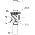
한편, 2분할한 정극시트 혹은 부극시트를 저항용접하는 경우는, 분할한 시트 한쪽씩을 용접하는 방법 혹은 분할한 시트를 동시에 용접하는 시리즈 스폿 용접이 검토되고 있지만, 용접회수의 삭감을 고려하면 시리즈 스폿 용접이 바람직하다. 종래의 시리즈 스폿 용접 기술에서는, 도 10에 나타낸 바와 같이, 용접용의 한 쌍의 저항용접용 전극봉(71 및 72)과 동축상에서 피용접부재(73 및 74)를 2점 용접하는 경우에는 'コ'자형의 용접용 부품(75)을 중간에 개재시켜, 'コ'자형의 용접용 부품(75)의 상하를 용접하는 방법이 주로 이용되고 있었다. 이 방법은, 'コ'자형의 용접용 부품(75)은 판상의 판금으로부터 용이하게 제작할 수 있는 것, 저항용접을 용이하고 안정화시키기 위한 프로젝션의 제작이 용이한 것이기 때문에 널리 일반적으로 이용되고 있다. 그러나, 이 방법에서는 용접용의 전극봉(71 및 72)에 의한 가압에 의한 'コ'자형의 용접용 부품(75)의 변형을 없애기 위해서, 'コ'자형의 용접용 부품의 내부에 가압받이(76)나 통전용으로서 금속블록의 공급을 행하는 등의 대책이 필요하게 되어 용접설비의 복잡화의 과제가 있었다.On the other hand, in the case of resistance welding of two divided positive electrode sheets or negative electrode sheets, a method of welding one divided sheet or a series spot welding in which the divided sheets are welded at the same time has been considered. Welding is preferred. In the conventional series spot welding technique, as shown in FIG. 10, when two-point welding of the to-
본 발명은 상기와 같은 종래 기술의 문제점을 해결하기 위하여 이루어지는 것으로, 서로 2분할되어 있는 적층된 정극심체 노출부 및 부극심체 노출부를 각각의 심체 노출부와 집전용 부재와의 사이의 저저항화를 실현할 수 있어, 1회의 용접이면서 또한 안정적으로 저항용접 할 수 있는 저항용접용 통전블록, 이 통전블록을 이용한 밀폐전지의 제조방법 및 밀폐전지를 제공하는 것을 목적으로 한다.SUMMARY OF THE INVENTION The present invention has been made to solve the above problems of the prior art, and it is possible to reduce the resistance between the core exposed portion and the core exposed portion, which are divided into two parts, and the core exposed portion and the current collector member. It is an object of the present invention to provide a resistance welding energization block capable of realizing and stably welding resistance at the same time, a method of manufacturing a sealed battery using the energization block, and a sealed battery.
상기 목적을 달성하기 위해, 본 발명의 저항용접용의 통전블록은 금속블록의 대향하는 두 개의 면의 각각에 돌기가 형성되어 있는 것을 특징으로 한다.In order to achieve the above object, the conductive block for resistance welding of the present invention is characterized in that the projection is formed on each of the two opposite surfaces of the metal block.
본 발명의 저항용접용의 통전블록에 의하면, 저항용접시에 가압력을 인가해도 금속블록 부분이 변형하기 어렵고, 게다가, 금속블록의 대향하는 두 개의 면의 각각에 돌기가 형성되어 있으므로, 저항용접시에 이 돌기부분이 프로젝션으로서 작용하기 때문에, 전류가 집중하여 발열하기 쉬워지므로, 용접성이 안정화하며, 게다가, 용접부분의 품질이 양호하게 된다. 또한, 본 발명의 저항용접용의 통전블록의 형상은 원기둥 모양, 각기둥 모양, 타원기둥 모양 등, 변형하기 어려운 임의의 형상을 채용할 수 있다.According to the energizing block for resistance welding of the present invention, the metal block portion is hardly deformed even when a pressing force is applied during resistance welding, and in addition, projections are formed on each of the two opposing faces of the metal block. Since the projections act as projections, current tends to concentrate and generate heat, so that weldability is stabilized and the quality of the welded portions is good. In addition, the shape of the energization block for resistance welding of this invention can employ arbitrary shapes which are hard to deform | transform, such as a cylinder shape, a prismatic cylinder shape, and an elliptic cylinder shape.
또, 본 발명의 저항용접용의 통전블록에서는 상기 금속블록의 상기 대향하는 2개의 면과 측면과의 사이의 각부(角部)는 모따기되어 있는 것이 바람직하다.Moreover, in the energization block for resistance welding of this invention, it is preferable that the corner part between two opposing surfaces and side surfaces of the said metal block is chamfered.
본 발명의 저항용접용의 통전블록에 의하면, 금속블록의 대향하는 두 개의 면과 측면과의 사이의 각부가 모따기되어 있으므로, 통전블록을 예를 들면 적층된 심체 노출부의 사이에 삽입하는 경우 등, 유연한 피용접부와 맞닿게 할 때에도 피용접부에 손상을 주는 것이 적게 되어, 용이하게 피용접부와 맞닿게 할 수 있게 되므로, 용접성이 향상한다.According to the current-carrying block for resistance welding of the present invention, since the corners between two opposing surfaces and side surfaces of the metal block are chamfered, for example, when the current-carrying block is inserted between stacked core exposed parts, When making contact with the flexible welded portion, damage to the welded portion is reduced, and the welded portion can be easily brought into contact with the welded portion.
또, 본 발명의 저항용접용의 통전블록에서는 상기 모따기되어 있는 면은 평면으로 되어 있는 것이 바람직하다.Moreover, in the energization block for resistance welding of this invention, it is preferable that the said chamfered surface is planar.
본 발명의 저항용접용의 통전블록에서는 모따기되어 있는 면은 곡면 및 평면의 양 태양을 취할 수 있다. 그렇지만, 모따기되어 있는 면을 평면으로 하면, 각부를 모따기되어 있는 면과 돌기가 형성된 면과의 사이가 피용접부에 대해서 반드시 둔각이 되므로, 본 발명의 저항용접용의 통전블록을 피용접물과 접촉시킬 때, 피용접물과 돌기가 접촉하기 쉬워지므로, 용접성이 향상한다.In the energization block for resistance welding of the present invention, the chamfered surface can take both curved and planar aspects. However, if the chamfered surface is a flat surface, the angle between the chamfered surface and the surface on which the projection is formed is always obtuse with respect to the welded portion. At the time, since the to-be-welded object and a projection become easy to contact, weldability improves.
이 경우에서는, 상기 돌기가 형성되어 있는 2개의 면은 각각 서로 평행한 평면부분이 마련되어 있는 것이 바람직하다.In this case, the two surfaces on which the projections are formed are preferably provided with planar portions parallel to each other.
저항용접용의 통전블록에서 대향하는 2개의 면과 측면과의 사이의 각부가 모따기되어 있는 경우, 돌기가 형성되어 있는 2개의 면에 평탄부분이 마련되지 않으면, 저항용접시에 저항용접용 전극으로 가압되었을 때에 통전블록이 변형하기 쉬워지고, 게다가. 저항용접시에 용융한 돌기부의 일부 혹은 용융한 피용접부재의 일부가 통전블록의 측면 측으로 흐르기 쉬워진다. 그에 대해, 본 발명의 저항용접용의 통전블록에서는 돌기가 형성되어 있는 2개의 면에 평탄부분이 마련되어 있으므로, 저항용접시에 저항용접용 전극으로 가압되었을 때에 통전블록이 변형하기 어려워지고, 또, 저항용접시에 용융변형한 돌기부의 일부 혹은 용융한 피용접부재의 일부가 이 평탄부에 머물러 통전부 블록의 측면방향으로 흘러나오는 것을 억제할 수 있으며, 게다가, 평탄부가 피용접부재와 접하는 면이 되기 때문에 통전블록이 안정화된다. 그 때문에, 본 발명의 저항용접용의 통전블록에 의하면, 신뢰성이 높은 저항용접부를 얻을 수 있게 된다.In the case of resistance welding, if each part between two opposing faces and side faces is chamfered, if a flat part is not provided on the two faces on which protrusions are formed, When pressurized, the energizing block is easily deformed, and moreover. At the time of resistance welding, a part of the molten protrusion part or a part of the molten welded member tends to flow to the side of the energization block. On the other hand, in the energization block for resistance welding of the present invention, since the flat portions are provided on two surfaces on which projections are formed, it is difficult to deform the energization block when pressed by the resistance welding electrode during resistance welding. During resistance welding, it is possible to prevent a part of the melt-deformed protrusion part or a part of the molten welded member from staying in the flat part and flowing out in the lateral direction of the energizing part block. As a result, the energization block is stabilized. Therefore, according to the energization block for resistance welding of this invention, a highly reliable resistance welding part can be obtained.
또, 본 발명의 저항용접용의 통전블록에서는 상기 돌기는 원추대(圓錐臺) 모양 또는 각추대(角錐臺) 모양인 것이 바람직하다.Moreover, in the energization block for resistance welding of this invention, it is preferable that the said protrusion is a truncated cone shape or a truncated cone shape.
본 발명의 저항용접용의 통전블록에 의하면, 저항용접시에 원추대 모양 또는 각추대 모양의 돌기의 선단 측에 전류가 집중하여 프로젝션으로서 작용하기 때문에, 보다 발열하기 쉬워져 용접성이 보다 안정화하고, 게다가, 용접부분의 품질이 보다 양호하게 된다.According to the current-carrying block for resistance welding of the present invention, the current concentrates on the tip side of the cone-shaped or pyramid-shaped projection during resistance welding, and thus acts as a projection, so that it is easier to generate heat and stabilizes weldability more. The quality of the welded portion becomes better.
또, 본 발명의 저항용접용의 통전블록에서는 상기 돌기에는 개구가 형성되어 있는 것이 바람직하다.Moreover, in the energization block for resistance welding of this invention, it is preferable that the opening is formed in the said processus | protrusion.
돌기에 개구가 형성되어 있지 않으면, 돌기부에서 발생한 열이 금속블록 전체로 확산되므로, 돌기의 선단의 온도가 상승하기 어려워진다. 그에 대해, 돌기에 개구가 형성되어 있으면, 그만큼 돌기부에 전류가 집중하기 때문에 돌기부에서 집중적으로 발열하기 쉬워지고, 게다가, 돌기부에서 발생한 열이 금속블록 전체에 확산되는 것을 방해할 수 있기 때문에, 돌기부 및 그 근방이 국부적으로 온도상승하므로, 양호하게 용접접속할 수 있게 된다. 이에 더하여, 돌기에 개구가 형성되어 있으면, 저항용접시에 가압력을 강하게 하면, 돌기의 개구가 붕괴되어 내부에 공동이 형성됨과 아울러, 붕괴된 부분은 돌기의 중앙부에 모이기 때문에, 저항용접시에 흐르는 전류는 일단 돌기의 개구의 주위로 분산된 후에 통전블록의 중앙부에 집중하므로, 돌기부분뿐만이 아니라, 돌기의 중앙부분에서도 양호하게 발열할 수 있어보다 양호하게 저항용접 할 수 있게 된다.If no opening is formed in the projections, heat generated in the projections diffuses to the entire metal block, making it difficult to increase the temperature at the tip of the projections. On the other hand, if an opening is formed in the projection, the current is concentrated in the projection, so that it is easy to generate heat intensively in the projection, and furthermore, since the heat generated in the projection can prevent the diffusion of the entire metal block, the projection and Since the temperature rises locally in the vicinity, welding can be satisfactorily connected. In addition, if an opening is formed in the projection, when the pressing force is increased during resistance welding, the opening of the projection collapses to form a cavity therein, and the collapsed portion gathers at the center of the projection, and thus flows during resistance welding. Since the electric current is concentrated around the central portion of the energization block once it is distributed around the opening of the projection, heat can be satisfactorily generated not only in the projection but also in the central portion of the projection, so that the resistance welding can be performed better.
또, 본 발명의 저항용접용의 통전블록에서는, 상기 개구는 상기 금속블록의 내부까지 연장해 있는 것이 바람직하다.In the energization block for resistance welding of the present invention, the opening preferably extends to the inside of the metal block.
개구가 금속블록의 내부까지 연장해 있으면, 용접시에 저항용접용 전극봉에서 강하게 끼워 돌기의 선단이 붕괴되는 상태로 했을 경우에서도 보다 확실히 돌기 혹은 금속블록의 내부에 공동이 존재하는 상태가 된다. 그 때문에, 돌기부에서 발생한 열이 확산하는 것을 방지하고, 돌기부 및 그 근방을 국부적으로 고온으로 할 수 있다. 또, 돌기 근방의 금속블록의 내부에 공동이 존재함으로써, 돌기부에서 발생한 열이 금속블록 전체로 확산되는 것을 효과적으로 방지할 수 있다. 따라서, 본 발명의 저항용접용의 통전블록에 의하면, 보다 양호하고 또한 확실하게 저항용접 할 수 있게 된다.When the opening extends to the inside of the metal block, even when the tip of the protrusion is strongly collapsed in the resistance welding electrode during welding, the cavity or the cavity is more reliably present inside the metal block. Therefore, the heat generated in the projections can be prevented from diffusing, and the projections and the vicinity thereof can be locally heated to a high temperature. In addition, by the presence of a cavity inside the metal block near the projection, it is possible to effectively prevent the heat generated in the projection from diffusing to the entire metal block. Therefore, according to the energization block for resistance welding of this invention, resistance welding can be performed more reliably and reliably.
또, 본 발명의 저항용접용의 통전블록에서는, 상기 개구는 상기 금속블록을 관통하고 있는 것으로 할 수 있다.In the energization block for resistance welding according to the present invention, the opening may pass through the metal block.
저항용접용의 통전블록은 돌기부분 이외는 저항용접시의 가압력에 의해서도 변형하기 어렵고, 게다가 저항이 작으면 좋다. 본 발명의 저항용접용의 통전블록에 의하면, 개구는 상기 금속블록을 관통하고 있으므로, 금속블록은 통 모양으로 되어 있으므로, 경량이면서 용이하게 상기 효과를 발휘하는 통전블록을 얻을 수 있다.The energizing block for resistance welding is hardly deformable by the pressing force at the time of resistance welding except for the protruding portion, and the resistance may be small. According to the current-carrying block for resistance welding of the present invention, since the opening penetrates through the metal block, the metal block is in the shape of a cylinder, whereby a current-carrying block having a light weight and easy effect can be obtained.
또, 본 발명의 저항용접용의 통전블록에서는, 상기 돌기의 주위에는 환상으로 절연씰재가 형성되어 있는 것이 바람직하다.Moreover, in the energization block for resistance welding of this invention, it is preferable that the insulation sealing material is formed cyclically around the said processus | protrusion.
저항용접용의 통전블록의 돌기의 주위에 환상으로 절연씰재가 형성되어 있으면, 저항용접시에 스퍼터된 고온의 먼지 입자가 발생해도 이 고온의 먼지 입자를 절연씰재와 돌기와의 사이 내지 절연씰재 자체에서 포획할 수 있다. 그 때문에, 본 발명의 저항용접용의 통전블록에 의하면, 저항용접시에 스퍼터된 고온의 먼지 입자가 통전블록의 주위로 비산하기 어려워지기 때문에, 스퍼터된 고온의 먼지 입자에 기인하는 피용접물의 손상 내지 주위에 주는 악영향이 억제된다.If an insulating seal material is formed annularly around the projection of the current-carrying block for resistance welding, even if hot dust particles sputtered during resistance welding are generated, the high temperature dust particles are separated between the insulating seal material and the projections or from the insulating seal material itself. Can be captured. Therefore, according to the energization block for resistance welding of this invention, since the hot dust particle sputtered at the time of resistance welding becomes difficult to scatter around an electricity supply block, damage of the to-be-welded object resulting from sputtered high temperature dust particle is carried out. The adverse effect to the surroundings is suppressed.
또한, 절연씰재는 스퍼터된 고온의 먼지 입자의 포획 특성을 향상시키기 위해서, 절연성 열용착성 수지로 형성하면 된다. 절연씰재로서 절연성 열용착성 수지를 사용하면, 저항용접시에 발생하는 스퍼터된 고온의 먼지 입자는 고체의 절연성 열용착성 수지를 부분적으로 용융함으로써 열이 빼앗겨 급속히 냉각되어 온도가 내려가므로, 용이하게 고체의 절연성 열용착성 수지 중에 포획된다. 또한, 저항용접시에는 전류를 흘리는 시간은 짧고, 게다가, 전류가 흐르는 범위는 좁기 때문에, 절연성 열용착성 수지의 모두가 동시에 용융하는 것은 적다. 그 때문에, 저항용접시에 발생한 스퍼터된 먼지 입자는 다시 절연성 열용착성 수지로부터 비산하는 것이 적게 된다. 또한, 절연성 열용착성 수지는 용착온도가 70 ~ 150℃정도이며, 용해온도는 200℃ 이상인 것이 바람직하다.Moreover, what is necessary is just to form an insulating sealing material with insulating thermosetting resin, in order to improve the trapping characteristic of the hot dust particle sputtered. When insulating thermosetting resin is used as the insulating seal material, sputtered high temperature dust particles generated during resistance welding are easily melted by partially melting the solid insulating thermosetting resin and rapidly cooled to lower the temperature. It is trapped in solid insulating thermosetting resin. In addition, since the time which an electric current flows at the time of resistance welding is short, and the range which an electric current flows is narrow, few of all the insulating thermosetting resins melt | fuse simultaneously. Therefore, the sputtered dust particle which generate | occur | produced at the time of resistance welding is less scattered from an insulating thermosetting resin again. Moreover, it is preferable that welding temperature of insulation thermosetting resin is about 70-150 degreeC, and melting temperature is 200 degreeC or more.
또, 본 발명의 저항용접용의 통전블록에서는, 상기 절연씰재는 높이가 상기 돌기보다도 낮게 되어 있는 것이 바람직하다.Moreover, in the energization block for resistance welding of this invention, it is preferable that the said height of the said insulating seal material is lower than the said processus | protrusion.
저항용접부에 대해서는, 피용접물은 저항용접용 전극에 의해서 통전블록 측을 향해서 가압되기 때문에, 통전블록의 돌기는 피용접부 측으로 파고드는 상태가 된다. 본 발명의 저항용접용 통전블록에 의하면, 절연씰재는 높이가 돌기보다 낮게 되어 있으므로, 저항용접시에는 피용접물과 접하게 되고, 스퍼터된 고온의 먼지 입자가 통전블록의 주위로 튀어나오지 않도록 됨과 아울러, 피용접물이 연질의 것이라도 절연씰재와 접하는 것에 의해서 피용접물에 과도한 변형이 생기기 어려워진다.With respect to the resistance welding portion, the object to be welded is pressed toward the current carrying block side by the electrode for resistance welding, so that the projection of the current carrying block penetrates to the side to be welded. According to the resistance welding energizing block of the present invention, since the insulating seal material is lower than the height of the protrusion, the welding sealant is brought into contact with the object to be welded, and sputtered hot dust particles do not protrude around the energizing block. Even if the to-be-welded material is a soft thing, it will be hard to cause excessive deformation in a to-be-welded material by contacting an insulating sealing material.
또한, 상기 목적을 달성하기 위해, 본 발명의 밀폐전지의 제조방법은 이하의 (1) ~ (5)의 공정을 포함하는 것을 특징으로 한다.Moreover, in order to achieve the said objective, the manufacturing method of the sealed battery of this invention is characterized by including the process of the following (1)-(5).
(1) 정극시트와 부극시트를 세퍼레이터를 통하여 감아돌림 또는 적층함으로써, 양단부에 각각 복수 매의 정극심체 노출부 및 부극심체 노출부가 형성된 편평형 전극체를 제작하는 공정,(1) a step of manufacturing a flat electrode body having a plurality of positive electrode core exposed portions and negative electrode core exposed portions respectively formed at both ends by winding or laminating a positive electrode sheet and a negative electrode sheet through a separator;
(2) 상기 적층된 정극심체 노출부 및 부극심체 노출부 중 적어도 어느 한쪽의 심체 노출부를 2분할하는 공정,(2) dividing the core exposed portion of at least one of the stacked positive core exposed portion and the negative core exposed portion into two;
(3) 상기 2분할된 심체 노출부의 최외측의 양표면에 각각 집전부재 또는 용접 받이부재를 배치함과 아울러, 상기 2분할된 심체 노출부간에 금속블록의 대향하는 두 개의 면의 각각에 돌기가 형성되어 있는 통전블록을 상기 대향하는 두 개의 면의 각각의 돌기가 상기 2분할된 심체 노출부와 접하도록 배치하는 공정,(3) A current collector member or a welding receiving member is disposed on both outermost surfaces of the two divided core exposed portions, and projections are provided on each of two opposite surfaces of the metal block between the two divided core exposed portions. Arranging the energized block formed so that each of the projections of the two opposing faces contacts the divided body exposed portion;
(4) 상기 2분할된 심체 노출부의 최외측의 양표면에 각각 배치되어 있는 집전부재 또는 용접 받이부재간에 한 쌍의 저항용접용 전극을 맞닿게 하는 공정,(4) a step of bringing a pair of resistance welding electrodes into contact between the current collecting member or the welding receiving member disposed on both outermost surfaces of the two divided core exposed portions;
(5) 상기 한 쌍의 저항용접용 전극간에 가압력을 인가하면서 저항용접을 행하는 공정.(5) A step of performing resistance welding while applying a pressing force between the pair of resistance welding electrodes.
본 발명의 밀폐전지의 제조방법에서는 적층된 정극심체 노출부 및 부극심체 노출부 중 적어도 어느 한쪽을 2분할하고, 이 2분할된 심체 노출부의 최외측의 양표면에 각각 집전부재 또는 용접 받이부재를 배치하며, 2분할된 심체 노출부간에 각각 금속블록의 양단에 돌기가 형성되어 있는 통전블록을 양단의 돌기가 2분할된 심체 노출부와 접하도록 배치하고, 심체 노출부의 최외측의 양표면에 각각 배치되어 있는 집전부재 또는 용접 받이부재간에 한 쌍의 저항용접용 전극을 맞닿으며, 한 쌍의 저항용접용 전극간에 가압력을 인가하면서 저항용접을 행하는 공정을 포함하고 있다. 이와 같은 저항용접 공정에서는 저항용접전류는 집전부재 또는 용접 받이부재 → 심체 노출부 → 통전블록 → 심체 노출부 → 집전부재 또는 용접 받이부재로 흐르므로, 한 번의 저항용접으로 한쪽의 전극시트 측의 심체 노출부와 집전부재를 용접할 수 있다.In the method for manufacturing a sealed battery according to the present invention, at least one of the stacked positive core exposed portions and the negative core exposed portions is divided into two, and a current collector member or a welding receiving member is provided on both outermost surfaces of the divided core exposed portions, respectively. And an energizing block having projections formed at both ends of the metal block between the two divided core exposed portions so as to be in contact with the core exposed portion divided into the two divided projections, respectively on both outermost surfaces of the core exposed portion. And a pair of resistance welding electrodes abutting between the current collector member or the welding receiving member arranged, and performing resistance welding while applying a pressing force between the pair of resistance welding electrodes. In this resistance welding process, the resistance welding current flows to the current collecting member or the welding receiving member → core exposed part → the current carrying block → core exposed part → the current collecting member or the welding receiving member, so that the core on one electrode sheet side with one resistance welding The exposed portion and the current collecting member can be welded.
게다가, 통전블록에는 돌기가 형성되어 있기 때문에, 저항용접시에 이 돌기부분에 전류가 집중하기 때문에 발열하기 쉬워지므로, 각각 전극시트의 집전부재 또는 용접 받이부재와 심체 노출부와의 사이 및 심체 노출부와 통전블록의 사이(각각 2개소)의 저항용접부분을 양호하게 저항용접 할 수 있게 된다. 또한, 본 발명에서는 각각의 전극시트의 2분할된 심체 노출부의 최외측의 양표면에 각각 배치되어 있는 것이 용접 받이부재이면, 통전블록을 집전부재로서 접속부재 등을 이용하여 외부단자와 전기적으로 접속하면 좋다. 그 때문에, 본 발명의 밀폐전지의 제조방법에 의하면, 각각의 전극시트의 심체 노출부와 집전부재와의 사이의 전기저항이 낮아지므로, 내부저항이 작은 밀폐전지를 제조할 수 있게 된다.In addition, since projections are formed in the energization block, current is concentrated in the projections during resistance welding, and thus heat generation is easy, so that the current collector member or the welding receiving member of the electrode sheet and the core exposed portion are exposed to each other. Resistance welding between the part and the conduction block (two locations each) can be well welded. In the present invention, if the welding receiving member is disposed on both outermost surfaces of the two-split core exposed portion of each electrode sheet, the current-carrying block is electrically connected to the external terminal using a connecting member or the like as a current collecting member. Do it. Therefore, according to the manufacturing method of the sealed battery of this invention, since the electrical resistance between the core exposed part of each electrode sheet and a collector member becomes low, it becomes possible to manufacture the sealed battery with small internal resistance.
이에 더하여, 본 발명의 밀폐전지의 제조방법에서는 복수 매의 정극심체 노출부 내지 부극심체 노출부는 적층되어 2분할되어 있기 때문에, 하나의 저항용접 개소에서 용접해야 하는 정극심체 노출부 내지 부극심체 노출부의 적층 매수는 반감되어 있고, 보다 적은 전력으로 저항용접 할 수 있게 된다. 또한, 2분할된 심체 노출부의 최외측의 양표면에 각각 집전부재 또는 용접 받이부재를 배치하는 공정과 2분할된 심체 노출부간에 금속블록의 대향하는 두 개의 면의 각각에 돌기가 형성되어 있는 통전블록을 대향하는 두 개의 면의 각각의 돌기가 2분할된 심체 노출부와 접하도록 배치하는 공정은, 어느 쪽이 앞에 있어도 되고, 어느 쪽이 다음에 있어도 된다, 또, 상기 (2) ~ (5)의 각 공정은 정극 측 및 부극 측의 쌍방에 적용해도 되고, 어느 한쪽에만 적용해도 된다.In addition, in the manufacturing method of the sealed battery of the present invention, since the plurality of the positive electrode core exposed portions to the negative electrode core exposed portions are stacked and divided into two parts, the positive electrode core exposed portions to the negative electrode core exposed portions to be welded at one resistance welding point. The number of laminated sheets is halved, and resistance welding can be performed with less power. In addition, a process of arranging a current collecting member or a welding receiving member on each of the outermost surfaces of the two-part core exposed portion, and an electric current having projections formed on each of two opposite surfaces of the metal block between the two-part core exposed parts. In the step of arranging the blocks so that the respective projections of the two surfaces facing each other are in contact with the divided body exposed portion, which one may be in front or which one may be next, and (2) to (5) above. Each step of) may be applied to both the positive electrode side and the negative electrode side, or may be applied to either one.
또, 본 발명의 밀폐전지의 제조방법에서는 상기 통전블록으로서 상기 금속블록의 상기 대향하는 2개의 면과 측면과의 사이의 각부는 모따기되어 있는 것을 이용하는 것이 바람직하다.Moreover, in the manufacturing method of the sealed battery of this invention, it is preferable to use what chamfered between each of the opposing two surfaces and side surfaces of the said metal block as said energization block.
본 발명의 밀폐전지의 제조방법에 의하면, 통전블록을 적층된 심체 노출부의 사이에 삽입할 때에 적층된 심체 노출부에 손상을 주는 것이 적게 되어, 용이하게 적층된 심체 노출부의 용접위치까지 삽입시킬 수 있게 되어, 용접성이 향상한다.According to the manufacturing method of the sealed battery of the present invention, when inserting the energization block between the laminated core exposed portions, damage to the laminated core exposed portions is reduced, so that the welded core can be easily inserted to the welded position of the core exposed portions. This improves the weldability.
또, 본 발명의 밀폐전지의 제조방법에서는 상기 통전블록으로서 상기 금속블록의 상기 모따기되어 있는 부분이 평면으로 되어 있는 것을 이용하는 것이 바람직하다.Moreover, in the manufacturing method of the sealed battery of this invention, it is preferable to use that the said chamfered part of the said metal block is planar as the said energization block.
본 발명의 밀폐전지의 제조방법에 의하면, 각부를 모따기되어 있는 면 및 돌기가 형성된 면과 적층된 심체 노출부와의 사이가 반드시 둔각이 되기 때문에, 통전블록을 적층된 심체 노출부의 사이에 삽입할 때에 적층된 심체 노출부와 돌기가 접촉하기 쉬워지므로, 용접성이 향상한다.According to the manufacturing method of the sealed battery according to the present invention, since an obtuse angle is formed between the chamfered surface and the surface on which the projection is formed and the laminated core exposed portion, an energization block can be inserted between the laminated core exposed portions. Since the core exposed portion and the projection are easily in contact with each other at the time, the weldability is improved.
또, 본 발명의 밀폐전지의 제조방법에서는 상기 통전블록으로서 상기 금속블록의 상기 돌기가 형성되어 있는 2개의 면에는 각각 서로 평행한 평면부분이 마련되어 있는 것을 이용하는 것이 바람직하다.Moreover, in the manufacturing method of the sealed battery of this invention, it is preferable to use what the planar part parallel to each other is provided in the two surfaces in which the said processus | protrusion of the said metal block is formed as said energization block.
본 발명의 밀폐전지의 제조방법에 의하면, 저항용접시에 저항용접용 전극으로 가압되었을 때에 통전블록이 변형하기 어려워지고, 또, 저항용접시에 용융변형한 돌기부의 일부 혹은 용융한 심체의 일부가 이 평탄부에 머물러 통전부 블록의 측면방향으로 흘러나오는 것을 억제할 수 있으며, 게다가, 평탄부가 피용접부재와 접하는 면이 되기 때문에 통전블록이 안정화되므로, 신뢰성이 높은 저항용접부를 얻을 수 있게 된다.According to the manufacturing method of the sealed battery of the present invention, it is difficult to deform the energization block when pressurized by the resistance welding electrode during resistance welding. It can be restrained from remaining in this flat part and flowing out in the lateral direction of the energizing part block. Moreover, since the energizing block is stabilized since the flat part is in contact with the member to be welded, a highly reliable resistance welded part can be obtained.
또, 본 발명의 밀폐전지의 제조방법에서는 상기 통전블록으로서 돌기가 원추대 모양 또는 각추대 모양인 것을 사용하는 것이 바람직하다.In the manufacturing method of the sealed battery of the present invention, it is preferable to use a projection having a truncated cone shape or a truncated cone shape as the energizing block.
본 발명의 밀폐전지의 제조방법에 의하면, 저항용접시에 원추대 모양 또는 각추대 모양의 돌기의 선단 측에 전류가 집중하기 때문에, 보다 발열하기 쉬워져 용접성이 보다 안정화하고, 게다가, 용접부분의 품질이 보다 양호한 밀폐전지를 제조할 수 있게 된다.According to the manufacturing method of the sealed battery of the present invention, since the current concentrates on the tip side of the cone-shaped or pyramidal-shaped protrusion during resistance welding, it is easier to generate heat, the weldability is more stabilized, and the quality of the welded portion is improved. It is possible to manufacture a better sealed battery.
또, 본 발명의 밀폐전지의 제조방법에서는 상기 통전블록으로서 상기 돌기에 개구가 형성되어 있는 것을 사용하는 것이 바람직하다.Moreover, in the manufacturing method of the sealed battery of this invention, it is preferable to use what the opening is formed in the said projection as said energization block.
돌기에 개구가 형성되어 있으면, 그만큼 돌기부에 전류가 집중하기 때문에, 돌기부에서 집중적으로 발열하기 쉬워진다. 그 때문에, 본 발명의 밀폐전지의 제조방법에 의하면, 보다 내부저항이 작고, 게다가, 용접부분의 품질이 양호한 밀폐전지를 제조할 수 있게 된다.If openings are formed in the projections, current concentrates on the projections by that amount, so that the heat generation in the projections can be concentrated. Therefore, according to the manufacturing method of the sealed battery of this invention, it becomes possible to manufacture the sealed battery which has a lower internal resistance, and also the quality of the weld part is favorable.
또, 본 발명의 밀폐전지의 제조방법에서는 상기 통전블록으로서 상기 개구가 상기 금속블록의 내부까지 연장해 있는 것을 사용하는 것이 바람직하다.Moreover, in the manufacturing method of the sealed battery of this invention, it is preferable to use what the said opening extended to the inside of the said metal block as said energization block.
개구가 금속블록의 내부까지 연장해 있으면, 용접시에 저항용접용 전극봉으로 강하게 끼워 돌기의 선단이 붕괴되는 상태로 했을 경우에서도, 저항용접시에 돌기의 선단부가 용융했을 경우에서도, 보다 확실히 돌기 혹은 금속블록의 내부에 공동이 존재하는 상태가 된다. 그 때문에, 돌기부에서 발생한 열이 확산하는 것을 방지하고, 돌기부 및 그 근방을 국부적으로 고온으로 할 수 있다. 또, 돌기 근방의 금속블록의 내부에 공동이 존재함으로써, 돌기부에서 발생한 열이 금속블록 전체적으로 확산되는 것을 효과적으로 방지할 수 있다. 따라서, 본 발명의 밀폐전지의 제조방법에 의하면, 보다 내부저항이 작고, 게다가, 용접부분의 품질이 양호한 밀폐전지를 제조할 수 있게 된다.If the opening extends to the inside of the metal block, even when the tip end of the protrusion is strongly collapsed by the electrode for resistance welding at the time of welding, even when the tip part of the protrusion melts at the time of resistance welding, the protrusion or the metal The cavity is in a state inside the block. Therefore, the heat generated in the projections can be prevented from diffusing, and the projections and the vicinity thereof can be locally heated to a high temperature. In addition, by the presence of a cavity inside the metal block near the projection, it is possible to effectively prevent the heat generated in the projection from spreading throughout the metal block. Therefore, according to the manufacturing method of the sealed battery of this invention, it becomes possible to manufacture the sealed battery which has a smaller internal resistance and the quality of the weld part is more favorable.
또, 본 발명의 밀폐전지의 제조방법에서는 상기 통전블록으로서 상기 개구가 상기 금속블록을 관통하고 있는 것을 사용할 수 있다.In the manufacturing method of the sealed battery according to the present invention, the opening block penetrates the metal block can be used.
개구가 금속블록을 관통하고 있는 경우, 금속블록은 통 모양이 되므로, 가벼워진다. 게다가, 통 모양의 금속블록은 개구의 중심축방향에 따른 방향으로 가해지는 힘에 대해서는 강도가 강하고, 변형하기 어렵다. 그 때문에, 본 발명의 밀폐전지의 제조방법에 의하면, 경량이면서 용이하게 상기 효과를 발휘하는 밀폐전지를 제조할 수 있게 된다.When the opening penetrates through the metal block, the metal block becomes cylindrical, and thus lighter. In addition, the cylindrical metal block is strong in strength and hardly deformed with respect to the force applied in the direction along the central axis direction of the opening. Therefore, according to the manufacturing method of the sealed battery of this invention, it becomes possible to manufacture the sealed battery which exhibits the said effect lightly and easily.
또, 본 발명의 밀폐전지의 제조방법에서는 상기 통전블록으로서 상기 돌기의 주위에 환상으로 절연씰재가 형성되어 있는 것을 이용하는 것이 바람직하다.Moreover, in the manufacturing method of the sealed battery of this invention, it is preferable to use what the insulating sealing material is formed annularly around the said projection as said energization block.
저항용접용의 통전블록의 돌기의 주위에 환상으로 절연씰재가 형성되어 있으면, 저항용접시에 스퍼터된 고온의 먼지 입자가 발생해도 이 고온의 먼지 입자를 절연씰재와 돌기와의 사이 내지 절연씰재 자체로 포획할 수 있다. 그 때문에, 본 발명의 밀폐전지의 제조방법에 의하면, 저항용접시에 스퍼터된 고온의 먼지 입자가 통전블록의 주위로 비산하기 어려워지기 때문에, 스퍼터된 고온의 먼지 입자에 기인하는 밀폐전지의 내부 단락이 생기기 어려워진다.If an insulating seal material is formed annularly around the projection of the current-carrying block for resistance welding, even if hot dust particles sputtered during resistance welding are generated, the high temperature dust particles may be separated from the insulating seal material and the projection to the insulating seal material itself. Can be captured. Therefore, according to the manufacturing method of the sealed battery of this invention, since the hot dust particle sputtered at the time of resistance welding becomes difficult to scatter to the circumference | surroundings of an energization block, the internal short circuit of the sealed battery resulting from the hot dust particle sputtered was performed. This becomes difficult to occur.
또한, 절연씰재는 스퍼터된 고온의 먼지 입자의 포획 특성을 향상시키기 위해서, 절연성 열용착성 수지로 형성하면 좋다. 절연씰재로서 절연성 열용착성 수지를 사용하면, 저항용접시에 발생하는 스퍼터된 고온의 먼지 입자는 고체의 절연성 열용착성 수지를 부분적으로 용융함으로써 열이 빼앗겨 급속히 냉각되어 온도가 내려가므로, 용이하게 고체의 절연성 열용착성 수지 중에 포획된다. 또한, 저항용접시에는 전류를 흘리는 시간은 짧고, 게다가, 전류가 흐르는 범위는 좁기 때문에, 절연성 열용착성 수지의 모두가 동시에 용융하는 것은 적다. 그 때문에, 저항용접시에 발생한 스퍼터된 먼지 입자는 절연성 열용착성 수지로부터 비산하여 편평형 전극체의 내부로 깊숙이 들어가는 것이 적게 되므로, 보다 내부 단락의 발생이 적고, 신뢰성이 높은 밀폐전지를 얻을 수 있다. 또한, 절연성 열용착성 수지는 용착온도가 70 ~ 150℃정도이며, 용해온도는 200℃ 이상의 것이 바람직하고, 또한 전해액 등에 대한 내약품성을 구비하고 있는 것이 바람직하다.Moreover, what is necessary is just to form an insulating sealing material with insulating thermosetting resin, in order to improve the trapping characteristic of sputtered high temperature dust particle. When insulating thermosetting resin is used as the insulating seal material, sputtered high temperature dust particles generated during resistance welding are easily melted by partially melting the solid insulating thermosetting resin and rapidly cooled to lower the temperature. It is trapped in solid insulating thermosetting resin. In addition, since the time which an electric current flows at the time of resistance welding is short, and the range which an electric current flows is narrow, few of all the insulating thermosetting resins melt | fuse simultaneously. Therefore, the sputtered dust particles generated during the resistance welding are less likely to scatter from the insulating thermosetting resin and deeply enter the inside of the flat electrode body, so that a sealed battery with less occurrence of internal short circuits and high reliability can be obtained. . Moreover, as for insulating thermosetting resin, welding temperature is about 70-150 degreeC, melt | dissolution temperature is preferably 200 degreeC or more, and it is preferable to have chemical-resistance with respect to electrolyte solution etc ..
또, 본 발명의 밀폐전지의 제조방법에서는, 상기 절연씰재는 높이가 상기 돌기보다 낮게 되어 있는 것을 이용하는 것이 바람직하다.Moreover, in the manufacturing method of the sealed battery of this invention, it is preferable to use what the height of the said insulating seal material is lower than the said processus | protrusion.
저항용접부에 대해서는, 적층된 심체 노출부는 저항용접용 전극에 의해서 통전블록 측을 향해서 가압되기 때문에, 통전블록의 돌기는 적층된 심체 노출부로 파고드는 상태가 된다. 본 발명의 밀폐전지의 제조방법에 의하면, 절연씰재는 높이가 돌기보다도 낮게 되어 있으므로, 저항용접시에는 적층된 심체 노출부와 접하게 되고, 스퍼터된 고온의 먼지 입자가 비산하여 편평형 전극체의 내부로 깊숙이 들어가는 것이 적게 됨과 아울러, 저항용접부 이외의 적층된 심체 노출부의 과도한 변형이 적게 되어, 보다 내부 단락의 발생이 적고, 신뢰성이 높은 밀폐전지를 얻을 수 있게 된다.With respect to the resistance welded portion, since the laminated core exposed portion is pressed toward the energizing block side by the resistance welding electrode, the projection of the energizing block is in a state of penetrating into the laminated core exposed portion. According to the manufacturing method of the sealed battery of the present invention, since the insulating seal material has a height lower than that of the projections, the resistance sealing contact with the laminated core exposed portion, the sputtered hot dust particles are scattered to the inside of the flat electrode body. In addition to being less deep, the excessive deformation of the laminated core exposed parts other than the resistance welded parts is reduced, resulting in less internal short circuits and a more reliable sealed battery.
또, 본 발명의 밀폐전지의 제조방법에서는 상기 통전블록으로서 상기 정극심체 노출부간 및 상기 부극심체 노출부간에서는 각각 상기 돌기의 형상이 다른 것을 이용하는 것이 바람직하다.In the manufacturing method of the sealed battery according to the present invention, it is preferable to use different shapes of the projections between the positive electrode core exposed portion and the negative electrode core exposed portion as the energization block.
예를 들면 리튬이온 2차전지에서는, 정극심체로서는 알루미늄 또는 알루미늄 합금이 사용되고, 부극심체로서는 동 또는 동합금이 사용되어 있는 것과 같이, 일반적인 밀폐전지의 정극심체 및 부극심체는 각각 다른 금속재료가 사용되고 있다. 동 또는 동합금은 알루미늄 또는 알루미늄 합금에 비해 전기저항이 작기 때문에, 부극심체 노출부 측의 저항용접은 정극심체 노출부 측의 저항용접보다 곤란하여, 적층된 부극심체 노출부 내에 용융하기 어려운 부분이 생기기 쉽다.For example, in a lithium ion secondary battery, aluminum or an aluminum alloy is used as the positive electrode core, and copper or copper alloy is used as the negative electrode core. As for the positive electrode core and the negative electrode core of a general sealed battery, different metal materials are used. . Since copper or copper alloy has lower electric resistance than aluminum or aluminum alloy, resistance welding on the negative electrode core exposed portion side is more difficult than resistance welding on the positive electrode core exposed portion side, resulting in a difficult to melt portion in the laminated negative electrode core exposed portion. easy.
본 발명의 밀폐전지의 제조방법에서는 통전블록으로서 정극심체 노출부간 및 부극심체 노출부간에서는 각각 돌기의 형상이 다른 것을 이용하도록 하고 있고, 정극심체 노출부 측 및 부극심체 노출부 측에서 각각 최적인 형상인 것을 선택하여 사용할 수 있다. 예를 들면, 정극심체 형성재료로서 알루미늄 또는 알루미늄 합금이 사용되어 있고, 부극심지 체형성재료로서 동 또는 동합금이 사용되어 있는 경우에는 부극심체 노출부간에 사용하는 통전블록의 돌기의 형상으로서는, 용접전류를 집중시켜 저항용접을 행하기 쉽게 하기 위해서, 돌기에 개구가 형성되어 있는 것을 사용하면 좋고, 또, 정극심체 노출부간에 사용하는 통전블록의 돌기의 형상으로서는 저항용접이 용이하게 진행하기 때문에, 통전블록이 보다 변형하기 어려워지도록 하기 위해서 돌기에 개구가 형성되어 있지 않은 것을 사용하면 좋다.In the manufacturing method of the sealed battery according to the present invention, the shape of the projections is different between the positive electrode core exposed portion and the negative electrode core exposed portion as the energization block, respectively. It can choose to use. For example, when aluminum or an aluminum alloy is used as the positive electrode core forming material, and copper or copper alloy is used as the negative electrode core forming material, the welding current is used as the shape of the projection of the energization block used between the negative electrode core exposed portions. In order to make it easy to perform resistance welding by concentrating, it is good to use the thing which has an opening formed in the processus | protrusion, and also as the shape of the processus | protrusion of the electricity supply block used between the positive electrode core exposed parts, resistance welding advances easily, In order to make a block harder to deform | transform, the thing which does not have an opening in a processus | protrusion may be used.
또, 본 발명의 밀폐전지의 제조방법에서는 상기 한 쌍의 저항용접용 전극간에 가압력을 인가하면서 저항용접을 행하는 공정에서 상기 개구가 반붕괴 상태가 되도록 가압력을 인가하는 것이 바람직하다.In the manufacturing method of the sealed battery of the present invention, it is preferable to apply a pressing force so that the opening is in a semi-collapsed state in the step of performing resistance welding while applying the pressing force between the pair of resistance welding electrodes.
돌기에 형성되어 있는 개구를 반붕괴 상태로 하면, 돌기의 개구가 붕괴되어 내부에 공동이 형성됨과 아울러 붕괴된 부분은 돌기의 중앙부에 모이므로, 저항용접시에 흐르는 전류는 일단 돌기의 개구의 주위로 분산된 후에 돌기의 중앙부에 집중한다. 그 때문에, 본 발명의 밀폐전지의 제조방법에 의하면, 돌기에 형성되어 있는 개구를 반붕괴 상태로 하지 않는 경우에 비해, 돌기의 주위 부분뿐만이 아니라 돌기의 중앙 부분에서도 양호하게 발열할 수 있으므로, 보다 양호하게 상기 효과를 발휘하는 밀폐전지를 제조할 수 있게 된다. 또한, 용접시에 가압함으로써, 돌기에 형성되어 있는 개구부분을 완전 붕괴 상태, 즉 돌기 혹은 통전블록의 내부에 공동이 형성되지 않는 상태로 해 버리면, 돌기에 개구를 형성하는 것의 효과가 적게 되므로, 바람직하지 않다.When the opening formed in the projection is in a semi-collapsed state, the opening of the projection collapses to form a cavity therein, and the collapsed portion accumulates at the center of the projection, so that the current flowing at the time of resistance welding once surrounds the opening of the projection. After dispersing, concentrate on the center of the protrusion. Therefore, according to the manufacturing method of the sealed battery of the present invention, heat can be generated not only in the peripheral portion of the protrusion but also in the center portion of the protrusion, as compared with the case where the opening formed in the protrusion is not in a semi-collapsed state. It is possible to manufacture a sealed battery that exhibits the above effects favorably. In addition, if the opening portion formed in the projection is pressurized at the time of welding, the effect of forming the opening in the projection is reduced since the opening portion formed in the projection is completely collapsed, that is, the cavity is not formed inside the projection or the energizing block. Not desirable
또한, 상기 목적을 달성하기 위해, 본 발명의 밀폐전지는 상기 어느 하나의 밀폐전지의 제조방법에 따라 제조된 것을 특징으로 한다.In addition, to achieve the above object, the sealed battery of the present invention is characterized in that it is manufactured according to any one of the manufacturing method of the sealed battery.
본 발명의 밀폐전지에 의하면, 종래예의 밀폐전지와 비교하여, 정극심체 노출부 내지 부극심체 노출부와 정극용 집전부재 내지 부극용 집전부재와의 사이의 저항용접부분의 전기저항이 낮아져, 보다 내부저항이 작은 밀폐전지가 된다.According to the sealed battery of the present invention, compared with the conventional sealed battery, the electrical resistance of the resistance welding portion between the positive electrode core exposed portion and the negative electrode core exposed portion and the positive electrode current collector member and the negative electrode current collector member is lowered, resulting in more internal It becomes a sealed battery with low resistance.
도 1의 A는 실시형태 1의 비수전해질 2차전지의 단면도이고, 도 1의 B는 도 1의 A의 IB-IB선에 따른 단면도이며, 도 1의 C는 도 1의 A의 IC-IC선에 따른 단면도이다.
도 2의 A는 실시형태 1의 정극용 통전블록의 평면도이고, 도 2의 B는 도 2의 A의 IIB-IIB선에 따른 단면도이며, 도 2의 C는 정면도이다.
도 3은 실시형태 1의 용접상태를 나타내는 측면도이다.
도 4는 도 3의 용접부분의 확대도이다.
도 5의 A는 돌기가 정극심체 노출부와 접촉하고 있는 부분이 링 모양인 경우의 저항용접전류가 흐르는 경로를 나타내는 도면이고, 도 5의 B는 도 5의 A의 발열이 강한 부분을 나타내는 도면이며, 도 5의 C는 돌기가 정극심체 노출부와 접촉하고 있는 부분이 원 모양인 경우의 저항용접전류가 흐르는 경로를 나타내는 도면이고, 도 5의 D는 도 5의 C의 발열이 강한 부분을 나타내는 도면이다.
도 6의 A는 실시형태 2의 통전블록의 정면도이고, 도 6의 B는 실시형태 2의 변형예의 통전블록의 정면도이며, 도 6의 C는 실시형태 3의 통전블록의 정면도이다.
도 7의 A는 실시형태 4의 통전블록의 정면도이고, 도 7의 B는 도 7의 A의 단면도이며, 도 7의 C는 환상의 절연씰재의 평면도이다.
도 8의 A는 종래의 축전소자로서의 전기 이중층 캐패시터의 단면도 이고, 도 8의 B는 도 8의 A의 VIIIB-VIIIB선에 따른 단면도이며, 도 8의 C는 도 8의 A의 VIIIC-VIIIC선에 따른 단면도이다.
도 9는 도 8에서의 전극의 심체 노출부와 집전용 부재와의 사이의 용접공정도를 나타내는 도면이다.
도 10은 종래의 시리즈 스폿 용접법을 설명하는 도면이다.FIG. 1A is a cross-sectional view of the nonaqueous electrolyte secondary battery of Embodiment 1, FIG. 1B is a cross-sectional view taken along line IB-IB of FIG. 1A, and FIG. 1C is an IC-IC of A of FIG. Sectional view along the line.
2: A is a top view of the energization block for positive electrodes of Embodiment 1, FIG. 2: B is sectional drawing along the IIB-IIB line | wire of A of FIG. 2, C is FIG.
3 is a side view showing a welding state of the first embodiment.
4 is an enlarged view of the welded portion of FIG. 3.
FIG. 5A is a diagram illustrating a path through which a resistance welding current flows when the portion where the protrusion contacts the positive electrode core exposed portion has a ring shape, and FIG. FIG. 5C is a diagram illustrating a path through which the resistance welding current flows when the portion where the protrusion is in contact with the positive electrode core exposed portion is in a circular shape, and FIG. It is a figure which shows.
6: A is a front view of the electricity supply block of Embodiment 2, FIG. 6B is a front view of the electricity supply block of the modification of Embodiment 2, C of FIG. 6 is a front view of the electricity supply block of Embodiment 3. FIG.
FIG. 7A is a front view of the energization block of Embodiment 4, FIG. 7B is a sectional view of A of FIG. 7, and C of FIG. 7 is a plan view of an annular insulating seal material.
FIG. 8A is a cross-sectional view of a conventional electric double layer capacitor as a power storage device, FIG. 8B is a cross-sectional view taken along line VIIIB-VIIIB of A of FIG. 8, and FIG. 8C is a line VIIIC-VIIIC of A of FIG. 8. In accordance with the cross-sectional view.
FIG. 9 is a view showing a welding process diagram between the core exposed portion of the electrode and the current collector member in FIG. 8.
It is a figure explaining the conventional series spot welding method.
이하에 본원 발명을 실시하기 위한 몇 개의 형태를 예시하여 상세하게 설명한다. 다만, 이하에 나타내는 각 실시형태는 본 발명의 기술 사상을 이해하기 위해서 예시하는 것으로서, 본 발명을 이들 실시형태에 특정하는 것을 의도하는 것이 아니라, 본 발명은 특허 청구의 범위에 나타낸 기술 사상을 일탈하지 않는 여러 가지의 변경을 행한 것에도 동일하게 적용할 수 있는 것이다. 또한 본 발명에서 사용 할 수 있는 발전요소는 정극시트와 부극시트를 세퍼레이터를 통하여 감아돌림 또는 적층함으로써, 양단부에 각각 복수 매의 정극심체 노출부 및 부극심체 노출부가 형성된 편평 모양의 것이지만, 이하에서는, 권회전극체를 대표적으로 설명한다.Below, some forms for implementing this invention are demonstrated in detail. However, each embodiment shown below is illustrated in order to understand the technical idea of this invention, and does not intend that this invention is specific to these embodiment, but this invention deviates from the technical idea shown by the claim. The same applies to various changes that are not made. In addition, the power generation element that can be used in the present invention is a flat shape formed by winding or laminating the positive electrode sheet and the negative electrode sheet through a separator, and having a plurality of positive electrode core exposed portions and negative electrode core exposed portions at both ends, respectively, The wound electrode body will be described representatively.
[실시형태 1]Embodiment 1
처음으로, 본 발명의 실시형태 1의 밀폐전지의 일례로서 각형의 비수전해질 2차전지를 도 1을 이용하여 설명한다. 또한, 도 1의 A는 실시형태 1의 비수전해질 2차전지의 단면도이고, 도 1의 B는 도 1의 A의 IB-IB선에 따른 단면도이며, 도 1의 C는 도 1의 A의 IC-IC선에 따른 단면도이다. 이 비수전해질 2차전지(10)는 정극시트와 부극시트가 세퍼레이터(모두 도시생략)를 통하여 감긴 편평 모양의 권회전극체(11)를 가지고 있다.First, as an example of the sealed battery of Embodiment 1 of this invention, a rectangular nonaqueous electrolyte secondary battery is demonstrated using FIG. 1A is a cross-sectional view of the nonaqueous electrolyte secondary battery of Embodiment 1, FIG. 1B is a cross-sectional view taken along line IB-IB of FIG. 1A, and FIG. 1C is an IC of A of FIG. 1. It is sectional drawing along IC line. This nonaqueous electrolyte
정극시트는 알루미늄박으로 이루어지는 정극심체의 양면에 띠모양의 알루미늄박이 노출되어 있는 정극심체 노출부(14)가 형성되도록 정극활물질 합제(合劑)를 도포하여, 건조 후에 압연함으로써 제작되어 있다. 또, 부극시트는 동박(銅箔)으로 이루어지는 부극심체의 양면에 띠모양의 동박이 노출되어 있는 부극심체 노출부(15)가 형성되도록 부극활물질 합제를 도포하여 건조 후에 압연함으로써 제작되어 있다. 그리고, 편평 모양의 권회전극체(11)는 정극시트 및 부극시트를 권회축방향의 양단부에 복수 매의 정극심체 노출부(14) 및 부극심체 노출부(15)가 각각 노출하도록, 예를 들면 폴리에틸렌제의 다공질 세퍼레이터를 통하여 편평 모양으로 감아돌림으로써 제작되어 있다.The positive electrode sheet is produced by applying a positive electrode active material mixture so as to form a positive electrode core exposed
복수 매의 정극심체 노출부(14)는 적층되어 정극용 집전부재(16)를 통하여 정극단자(17)에 접속되고, 마찬가지로 복수 매의 부극심체 노출부(15)는 적층되어 부극용 집전부재(18)를 통하여 부극단자(19)에 접속되어 있다. 또한, 정극단자(17), 부극단자(19)는 각각 절연부재(20, 21)를 통하여 봉구판(封口板)(13)에 고정되어 있다. 이 실시형태의 각형의 비수전해질 2차전지(10)는, 상술한 바와 같이 하여 제작된 편평 모양의 권회전극체(11)를 각형의 전지 외장캔(12) 내에 삽입한 후, 봉구판(13)을 전지 외장캔(12)의 개구부에 레이저 용접하고, 그 후, 전해액 주액구멍(22)으로부터 비수전해액을 주액하며, 이 전해액 주액구멍(22)을 밀폐함으로써 제작되어 있다.The plurality of positive electrode core exposed
편평 모양의 권회전극체(11)는, 정극시트 측에서는 적층된 복수 매의 정극심체 노출부(14)가 2분할되고, 그 사이에 정극용 통전블록(24A)이 끼워져 있으며, 동일하게 부극시트 측에서는 적층된 복수 매의 부극심체 노출부(15)가 2분할되어 그 사이에 부극용 통전블록(25)이 끼워져 있다. 또, 정극용 통전블록(24A)의 양측에 위치하는 정극심체 노출부(14)의 최외측의 양측의 표면에는 각각 정극용 집전부재(16)가 배치되어 있으며, 부극용 통전블록(25)의 양측에 위치하는 부극심체 노출부(15)의 최외측의 양측의 표면에는 각각 부극용 집전부재(18)가 배치되어 있다. 또한, 정극용 통전블록(24A)은 정극심체와 같은 재료인 알루미늄제이며, 부극용 통전블록(25)는 부극심체와 같은 재료인 동제이지만, 정극용 통전블록(24A) 및 부극용 통전블록(25)의 형상은 모두 실질적으로 동일한 것을 사용할 수 있다.In the flat
이들 정극용 집전부재(16)와 정극심체 노출부(14)와의 사이 및 정극심체 노출부(14)와 정극용 통전블록(24A)와의 사이(각각 2개소)는 모두 저항용접되어 있고, 또, 부극용 집전부재(18)와 부극심체 노출부(15)와의 사이 및 부극심체 노출부(15)와 부극용 통전블록(25)와의 사이(각각 2개소)는 모두 저항용접에 의해서 접속되어 있다.Resistance welding between the positive electrode
이하, 정극용 통전블록(24A) 및 부극용 통전블록(25)의 형상, 정극심체 노출부(14), 정극용 집전부재(16), 정극용 통전블록(24A)간의 저항용접방법 및 부극심체 노출부(15), 부극용 집전부재(18), 부극용 통전블록(25)간의 저항용접방법을 도 2 ~ 도 5를 이용하여 상세하게 설명한다. 그렇지만, 실시형태 1에서는 정극용 통전블록(24A) 및 부극용 통전블록(25)의 형상은 실질적으로 동일하며, 게다가, 정극심체 노출부(14), 정극용 집전부재(16), 정극용 통전블록(24A)간의 저항용접방법 및 부극심체 노출부(15), 부극용 집전부재(18), 부극용 통전블록(25)간의 저항용접방법은 정극시트 측의 것이라도 부극시트 측이라도 동일하므로, 이하에서는 정극시트 측의 것을 대표적으로 설명하는 것으로 한다.Hereinafter, the resistance welding method between the shape of the positive electrode
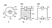
실시형태 1의 정극용 통전블록(24A)을 도 2를 이용하여 설명한다. 또한, 도 2의 A는 정극용 통전블록(24A)의 평면도이고, 도 2의 B는 도 2의 A의 IIB-IIB선에 따른 단면도이며, 도 2의 C는 정면도이다. 이 정극용 통전블록(24A)은 원기둥 모양의 본체(24a)의 대향하는 두 개의 면(24e)의 각각에 예를 들면 원추대 모양의 돌기(24b)가 형성되어 있다. 그리고, 이 원추대 모양의 돌기(24b)의 중앙부에는 선단측으로부터 원기둥 모양의 본체(24a)의 내부까지 개구(24c)가 형성되어 있으며, 또, 원기둥 모양의 본체(24a)의 대향하는 두 개의 면(24e)과 측면과의 사이에 각부(24f)가 형성되어 있다.The
이 원추대 모양의 돌기(24b)의 높이 H는 저항용접 부재에 일반적으로 형성되어 있는 돌기(프로젝션)와 동일한 정도, 즉, 수㎜ 정도이면 좋다. 또, 개구(24c)의 깊이 D는 여기에서는 원추대 모양의 돌기(24b)의 높이 H보다 크게 되고, 개구(24c)는 돌기(24b)가 형성된 원기둥 모양의 본체(24a)의 면(24e)으로부터 돌기(24b)의 높이 H의 깊이보다 얕은 위치까지 형성되어 있는(개구(24c)의 깊이 D는 2H보다 작음) 것이 바람직하고, 돌기(24b)가 형성된 원기둥 모양의 본체(24a)의 표면으로부터 돌기(24b)의 높이 H의 1/2의 깊이보다 얕은 위치까지 형성되어 있는(개구(24c)의 깊이 D는 3/2H보다 작음) 것이 보다 바람직하다. 개구(24c)의 깊이가 너무 깊으면, 원기둥 모양의 본체(24a)의 지름이 작은 경우에는 원기둥 모양의 본체(24a)의 도전성이 저하할 우려가 있으므로 바람직하지 않다.The height H of the
또, 원기둥 모양의 본체(24a)의 지름 및 길이는 편평 모양의 권회전극체(11)나 전지 외장캔(12)(도 1 참조)에 의해서도 변화하지만, 3㎜ ~ 수 10㎜정도이면 좋다. 또한, 여기에서는 정극용 통전블록(24A)의 본체(24a)의 형상은 원기둥 모양의 것으로 하여 설명했지만, 각기둥 모양, 타원기둥 모양 등, 금속제의 블록모양의 것이면 임의의 형상의 것을 사용할 수 있다. 또, 정극용 통전블록(24A)의 형성재료로서는 동, 동합금, 알루미늄, 알루미늄 합금, 텅스텐, 몰리브덴 등으로 이루어지는 것을 사용할 수 있고, 또한, 이들 금속으로 이루어지는 것 가운데, 돌기(24b)에 니켈도금을 시행한 것, 돌기(24b)와 그 근본 부근까지를 텅스텐 혹은 몰리브덴 등의 발열을 재촉하는 금속재료로 변경하며, 동, 동합금, 알루미늄 또는 알루미늄 합금으로 이루어지는 정극용 통전블록(24A)의 본체(24a)에 납땜 등에 의해서 접합한 것 등도 사용할 수 있다.The diameter and length of the cylindrical
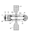
다음으로, 실시형태 1의 밀폐전지의 구체적 제조방법을 설명한다. 도 3에 나타낸 바와 같이, 편평 모양의 권회전극체(11)의 알루미늄박으로 이루어지는 정극심체 노출부(14)를 적층하고, 이 적층한 정극심체 노출부(14)를 권회 중앙부분으로부터 양측으로 2분할하며, 전극체 두께 H의 1/4H를 중심으로 하여 정극심체 노출부(14)를 집결시켰다. 그리고, 정극심체 노출부(14)의 최외주 측의 양측에 정극용 집전부재(16), 내주 측에 정극용 통전블록(24A)을, 정극용 통전블록(24A)의 양측의 원추대 모양의 돌기(24b)가 각각 정극심체 노출부(14)와 맞닿도록 배치했다. 여기에서, 집결시킨 알루미늄박의 두께는 한쪽 약 660㎛이며, 총적층수는 88매(한쪽 44매)이다. 또, 정극용 집전부재(16)는 두께 0.8㎜의 알루미늄판을 펀칭하여, 굽힘가공등으로 제작했다. 또한, 이 정극용 집전부재(16)는 알루미늄판으로부터 주조 등으로 제작해도 된다.Next, the specific manufacturing method of the sealed battery of Embodiment 1 is demonstrated. As shown in Fig. 3, the positive electrode core exposed
다음으로, 도 3에 나타낸 바와 같이, 상하에 배치된 한 쌍의 저항용접용 전극봉(31 및 32)간에 정극용 집전부재(16) 및 정극용 통전블록(24A)이 배치된 편평 모양의 권회전극체(11)를 배치하고, 한 쌍의 저항용접용 전극봉(31 및 32)을 각각 정극심체 노출부(14)의 최외주 측의 양측에 배치된 정극용 집전부재(16)에 맞닿게 한다. 그리고, 한 쌍의 저항용접용 전극봉(31 및 32)간에 적의의 압력을 인가하고, 미리 정한 일정한 조건으로 저항용접을 실시한다.Next, as shown in FIG. 3, the flat winding of the positive
돌기(24b)에는 개구(24c)가 형성되어 있기 때문에, 돌기의 선단부에 전류가 집중하기 쉽고, 또한 돌기의 선단이 심체 노출부에 파고들기 쉬워지기 때문에, 개구(24c)가 형성되어 있지 않은 경우보다 용접성이 향상한다. 그리고, 돌기(24b)의 선단부가 반붕괴 상태가 되어, 돌기(24b)가 정극심체 노출부(14)와 접촉하고 있는 부분이 링 모양으로부터 원 모양으로 변화하도록 압력을 가하여 저항용접을 행하면, 보다 안정적으로 용접을 행할 수 있다.Since the
따라서, 정극용 통전블록(24A)의 돌기(24b)의 형상은, 도 4에 나타내는 바와 같이, 돌기(24b)의 선단부가 반붕괴 상태가 되어 돌기(24b)가 정극심체 노출부(14)와 접촉하고 있는 부분이 링 모양으로부터 원 모양으로 변화하고 있도록 하는 것이 바람직하다. 또한, 도 4는 도 3의 용접부분의 확대도이다. 이 경우, 돌기(24b)의 내부에는 공동(24d)이 형성되어 있을 필요가 있다. 이것은 돌기(24b)의 정극심체 노출부(14)와의 접촉부를 원 모양으로 함으로써 정극용 통전블록(24A) 중심으로부터의 발열을 재촉하여, 더욱 안정된 용접이 가능하게 된다.Therefore, the shape of the
또한, 돌기(24b)가 정극심체 노출부(14)와 접촉하고 있는 부분이 반붕괴 상태가 되는지 링 모양이 되는지는 주로 용접시의 가압력에 의존하는 것을 알 수 있어, 용접 가압력이 약한 경우는 돌기 선단이 환상이 되고, 용접 가압력이 강한 경우는 돌기 선단이 반붕괴 상태가 되는 경향에 있다. 또, 그 외에는 돌기(24b)의 높이가 높고 또한 개구(24c)의 깊이가 깊을수록 반붕괴 상태가 되기 쉽고, 개구의 깊이가 얕은 경우는 돌기(24c)의 선단이 환상인 채로 심체 노출부로 파고드는 상태가 되기 쉬운 것이라고 생각된다.In addition, it can be seen that the part where the
또, 이 저항용접시에는 한 쌍의 저항용접용 전극봉(31 및 32)과 정극용 통전블록(24A)의 중심축이 일치하고 있는 것이 바람직하고, 정극용 통전블록(24A)은 가압 등에 의해 위치 어긋남 없이 보유지지되어 있는 것이 바람직하다. 또, 저항용접기로서는 주지의 트랜지스터 등을 이용한 반도체식 용접전원을 사용할 수 있다.In this resistance welding, it is preferable that the center axes of the pair of
여기에서, 상기의 돌기(24b)가 정극심체 노출부(14)와 접촉하고 있는 부분이 링 모양인 경우와 원 모양인 경우에서, 발열상태에 차이가 생기는 이유에 대해서, 도 5를 이용하여 설명한다. 또한, 도 5의 A는 돌기(24b)가 정극심체 노출부(14)와 접촉하고 있는 부분이 링 모양인 경우의 저항용접전류가 흐르는 경로를 나타내는 도면이고, 도 5의 B는 도 5의 A의 발열이 강한 부분을 나타내는 도면이며, 도 5의 C는 돌기(24b)가 정극심체 노출부(14)와 접촉하고 있는 부분이 링 모양인 경우의 저항용접전류가 흐르는 경로를 나타내는 도면이고, 도 5의 D는 도 5의 C의 발열이 강한 부분을 나타내는 도면이다.Here, the reason why the heat generation state is different in the case where the portion where the
전류는 가장 저항값이 적은 개소를 흐르기 때문에, 저항용접용 전극봉(31 및 32)의 내부에서는 그 중심이 가장 잘 전류가 흐르는 부분이 된다. 돌기(24b)가 정극심체 노출부(14)와 접촉하고 있는 부분이 링 모양인 경우, 도 5의 A에 나타내는 바와 같이, 용접전류 I는, 예를 들면 위쪽의 저항용접용 전극봉(31)으로부터 위쪽의 정극용 집전부재(16) 및 정극심체 노출부(14)를 거쳐, 정극용 통전블록(24A)의 위쪽의 돌기(24b)의 링 모양의 선단부로부터 링 모양으로 분류되어 정극용 통전블록(24A)의 본체(24a) 내로 흐르며, 또한, 정극용 통전블록(24A)의 하측의 돌기(24b)의 링 모양의 선단부를 지나 전류가 집중되어 하측의 정극심체 노출부(14) 및 정극용 집전부재(16)를 거쳐 하측의 저항용접용 전극봉(32)으로 흐른다.Since the current flows through the smallest resistance value, the center of the
그 때문에, 돌기(24b)가 정극심체 노출부(14)와 접촉하고 있는 부분이 링 모양인 경우, 돌기(24b)의 중심에는 전류가 흐르지 않기 때문에, 도 5의 B에 나타낸 바와 같이, 링 모양으로 용접의 기점이 발생하게 되어 용접의 기점이 다수가 된다.Therefore, when the part which the
그에 대해, 돌기(24b)가 정극심체 노출부(14)와 접촉하고 있는 부분이 반붕괴 상태가 되어 원 모양으로 되어 있는 경우, 돌기(24)의 내부에는 공동(24d)이 형성되어 있기 때문에, 도 5의 C에 나타내는 바와 같이, 용접전류 I는, 예를 들면 위쪽의 저항용접용 전극봉(31)으로부터 위쪽의 정극용 집전부재(16) 및 정극심체 노출부(14)를 거쳐 정극용 통전블록(24A)의 위쪽의 돌기(24b)의 원 모양의 선단부의 중심으로부터 링 모양으로 분류되어 정극용 통전블록(24A)의 본체(24a) 내에 흐르며, 또한, 정극용 통전블록(24A)의 하측의 돌기(24b)의 원 모양의 선단부의 중심을 지나 전류가 집중되어 하측의 정극심체 노출부(14) 및 정극용 집전부재(16)를 거쳐 하측의 저항용접용 전극봉(32)으로 흐른다.On the other hand, when the part in which the
이 예에서는, 용접전류 I는 돌기(24b) 부분에서 공동(24d) 부분을 피해 링 모양으로 전류가 분류되지만, 원 모양의 선단부의 중심의 내부에 공동(24d)이 존재하고 있기 때문에, 금속의 용융에 수반하는 흡열이 적게 되므로, 돌기(24b)의 원 모양의 선단부의 중심의 부근이 가장 발열하기 쉬워진다. 그 때문에, 돌기(24b)가 정극심체 노출부(14)와 접촉하고 있는 부분이 원 모양인 경우, 돌기(24b)의 원 모양의 선단부의 중심으로 전류가 집중하기 때문에, 용접전류 I에 의해서 강하게 발열하는 부분의 형상은, 도 5의 D에 나타낸 바와 같이, 구상(球狀)이 되므로, 보다 안정된 용접상태가 되며, 게다가, 용접강도도 강해진다.In this example, the welding current I is divided into rings in the
또한, 상기 실시형태 1에서는 정극용 통전블록(24A)으로서 기둥 모양의 본체(24a)를 가지고, 돌기(24b)로서 개구(24c)가 형성되어 있는 원추대 모양인 것을 이용한 예를 나타냈다. 그렇지만, 본 발명에서는, 돌기(24b)는 개구가 형성되어 있지 않은 것이라도, 각추대 모양의 것, 즉, 삼각추대 모양인 것이나 사각추대 모양인 것이나 또한 다각추대 모양인 것도 사용할 수 있다.In addition, in the said Embodiment 1, the example which used the thing of the cone shape which has the columnar
돌기(24b)에 개구가 형성되어 있지 않은 경우, 돌기(24b)의 작용은 종래의 저항용접시의 프로젝션과 동일하게 되지만, 이 경우에서도 양호하게 정극용 집전부재(16), 적층된 복수 매의 정극심체 노출부(14) 및 정극집전블록(24)와의 사이의 저항용접을 행할 수 있다. 전류, 통전시간, 가압압력을 변화시키지 않는 일정한 조건하에서는 돌기의 유무에 의해 저항용접부분의 용접상태는 크게 변화한다. 예를 들면, 돌기를 가지는 경우에 용접할 수 있는 일정한 조건(용접개소의 파괴시험으로, 10kgf 정도에서 파괴되는 조건)에서, 돌기가 없는 정극용 통전블록을 이용했을 경우에는 전혀 용접할 수 없고, 정극용 통전블록이 떨어져 버린다.In the case where no opening is formed in the
또, 정극집전블록(24)으로서 원기둥 모양의 본체(24a)를 가지는 것을 사용한 예를 나타냈지만, 정극집전블록(24)의 본체(24a)로서는 각기둥 모양, 타원기둥 모양 등의 금속제의 블록 모양인 것이면 되고, 또한 개구(24c)(도 2 참조)가 본체(24a)를 관통하고 있는 것도 사용할 수 있다. 특히, 개구(24c)(도 2 참조)가 본체(24a)를 관통하고 있는 경우는, 정극용 통전블록(24A)의 본체(24a)는 통 모양의 것이 되지만, 이 경우는 본체(24a)의 양단부를 성형하여 혹은 그대로 돌기로 하여 겸용시킬 수 있다.Moreover, although the example using what has the cylindrical
또한, 상기 실시형태 1에서는 적층된 복수 매의 정극심체 노출부(14)를 2분할하고, 정극용 집전부재(16) 및 정극용 통전블록(24A)을 이용하여 저항용접하는 경우에 대해 설명했지만, 정극용 통전블록(24A)을 정극용 집전부재에 겸용하여 이 정극용 통전블록(24A)을 정극단자(17)에 접속해도 된다. 이 경우, 상기 실시형태 1에서 사용되고 있는 정극용 집전부재를 바꾸어, 정극용 통전블록(24A)와 같은 재료로 형성된 박판재로 이루어지는 용접 받이부재를 이용하면 된다.Further, in the first embodiment, the case where the plurality of laminated positive electrode core exposed
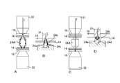
[실시형태 2]Embodiment 2
상기 실시형태 1의 정극용 통전블록(24A)으로서는, 도 2에 나타낸 바와 같이, 원기둥 모양의 본체(24a)의 대향하는 두 개의 면(24e)의 각각에 예를 들면 원추대 모양의 돌기(24b)가 형성되어 있는 것을 나타냈다. 이와 같이, 본체(24a)가 원기둥 모양이면, 원기둥 모양의 본체(24a)의 대향하는 두 개의 면(24e)과 측면과의 사이에 각부(24f)가 형성된다. 그 때문에, 도 3에 나타내는 바와 같이, 정극용 통전블록(24A)을, 적층된 정극심체 노출부(14)를 2분할하여 그 내측에 배치하고, 정극용 통전블록(24A)의 양측의 원추대 모양의 돌기(24b)가 각각 적층된 정극심체 노출부(14)와 맞닿도록 할 때, 각부(24f)가 적층된 정극심체 노출부(14)와 접촉하기 쉽기 때문에, 정극심체 노출부(14)가 변형되기 쉬워진다.As the positive
그래서, 실시형태 2의 정극용 통전블록(24B)로서는 실시형태 1의 원기둥 모양의 본체(24a)의 대향하는 두 개의 면(24e)과 측면과의 사이의 각부(24f)에 모따기되어 있는 면(24g)을 형성했다. 이 실시형태 2의 정극용 통전블록(24B)을 도 6의 A를 이용하여 설명한다. 또한, 도 6의 A는 실시형태 2의 정극용 통전블록(24B)의 정면도이다.Therefore, as the positive
이와 같이 모따기되어 있는 면(24g)을 형성한 실시형태 2의 정극용 통전블록(24B)에 의하면, 적층된 정극심체 노출부(14)를 2분할하여 그 내측에 정극용 통전블록(24B)의 양측의 원추대 모양의 돌기(24b)가 각각 정극심체 노출부(14)와 맞닿도록 배치할 때, 적층된 정극심체 노출부(14)에 손상을 주는 것이 적게 되어, 용이하게 적층된 정극심체 노출부(14)의 용접위치까지 삽입시킬 수 있게 되어, 용접성이 향상한다.According to the positive
또한, 실시형태 2의 정극용 통전블록(24B)에서의 모따기되어 있는 면(24g)은 곡면 및 평면 중 어느 쪽도 채용할 수 있지만, 모따기되어 있는 면(24g)을 평면 모양으로 하면, 모따기되어 있는 면(24g)과 돌기(24b)가 형성된 면과의 사이가 적층된 정극심체 노출부(14)에 대해서 반드시 둔각이 되므로, 정극용 통전블록(24B)을 적층된 정극심체 노출부(14)와 접촉시킬 때에 정극심체 노출부(14)와 돌기(24b)가 접촉하기 쉬워지므로, 보다 용접성이 향상한다.In addition, although the chamfered
또, 실시형태 2의 정극용 통전블록(24B)에서는, 도 6의 B에 변형예로서 나타낸 정극용 통전블록(24C)과 같이, 모따기되어 있는 면(24g)이 돌기(24b)의 형성부분까지 연장해 있어, 실시형태 2의 정극용 통전블록(24B)의 본체(24a)에서의 각각 서로 평행한 2개의 평면으로 이루어지는 면(24e)이 존재하지 않는 형상도 취할 수 있지만, 정극용 통전블록(24B)의 돌기(24b)가 형성되어 있는 2개의 면(24e)이 각각 노출되어 있는 상태, 즉, 정극용 통전블록(24B)의 본체(24a)에 각각 서로 평행한 2개의 평면으로 이루어지는 면(24e)이 형성되어 있는 상태로 하면, 저항용접시에 저항용접용 전극으로 가압되었을 때에 정극용 통전블록(24B)이 변형하기 어려워지고, 또, 저항용접시에 용융변형한 돌기(24b)의 일부 혹은 용융한 정극심체 노출부(14)의 일부가 이 면(24e)에 머물러 정극용 통전블록(24B)의 측면방향으로 흘러나오는 것이 억제되며, 게다가, 면(24e)이 정극심체 노출부(14)와 접하는 면이 됨으로써, 정극용 통전블록(24B)의 위치가 안정화되어, 보다 신뢰성이 높은 저항용접부를 얻을 수 있게 되기 때문에, 보다 바람직하다.Moreover, in the positive
[실시형태 3]Embodiment 3
또, 실시형태 2의 정극용 통전블록(24B)로서는 실시형태 1의 원기둥 모양의 본체(24a)의 대향하는 두 개의 면(24e)과 측면과의 사이의 각부(24f)에 모따기되어 있는 면(24g)을 형성함과 아울러, 돌기(24b)에 개구부가 형성되어 있지 않은 예를 나타냈다. 또, 실시형태 1의 정극용 통전블록(24A)으로서는 돌기(24b)에 형성한 개구(24c)의 깊이 D를 돌기(24b)의 높이 H보다 크게 한 예를 나타냈다(도 2의 B참조). 그렇지만, 돌기(24b)에 형성하는 개구(24c)의 깊이 D는 돌기(24b)의 높이 H보다 작게 해도 된다. 이와 같은 실시형태 3의 정극용 통전블록(24D)의 구성을 도 6의 C에 나타낸다. 또한 도 6의 C는 실시형태 3의 정극용 통전블록(24D)의 정면도이다.In addition, as the energizing
실시형태 3의 정극용 통전블록(24D)에 의하면, 적층된 정극심체 노출부(14)를 2분할하여 그 내측에 정극용 통전블록(24D)의 양측의 원추대 모양의 돌기(24b)가 각각 정극심체 노출부(14)와 맞닿도록 배치할 때, 적층된 정극심체 노출부(14)에 손상을 주는 것이 적게 되어, 용이하게 적층된 정극심체 노출부(14)의 용접위치까지 삽입시킬 수 있게 되어, 용접성이 향상한다. 이에 더하여, 원추대 모양의 돌기(24b)의 내부에 개구(24c)를 형성했기 때문에, 저항용접시에 원추대 모양의 돌기(24b)의 선단 측에 전류가 집중하기 때문에, 보다 발열하기 쉬워져, 용접성이 보다 안정화하며, 게다가, 용접부분의 품질이 보다 양호한 밀폐전지를 제조할 수 있게 된다.According to the positive
[실시형태 4]Embodiment 4
실시형태 4의 정극용 통전블록(24E)을 도 7을 이용하여 설명한다. 또한, 도 7의 A는 실시형태 4의 통전블록의 정면도이고, 도 7의 B는 도 7의 A의 단면도이며, 도 7의 C는 환상의 절연씰재의 평면도이다.The
실시형태 4의 정극용 통전블록(24E)은 도 6의 A에 나타낸 실시형태 2의 정극용 통전블록(24B)의 원추대 모양의 돌기(24b)의 주위에 환상의 절연성 열용착성 수지로 형성된 절연씰재(26)를 형성한 것이다. 이 절연씰재(26)의 높이는 원추대 모양의 돌기(24b)의 높이 H보다 낮게 되어 있다.The positive
이 실시형태 4의 정극용 통전블록(24E)을 적층된 정극심체 노출부(14)를 2분할하여 그 내측에 배치하고, 정극용 통전블록(24E)의 양측의 원추대 모양의 돌기(24b)가 각각 적층된 정극심체 노출부(14)와 맞닿도록 배치하면, 정극용 통전블록(24E)에는 모따기되어 있는 면(24g)이 형성되어 있기 때문에, 적층된 정극심체 노출부(14)를 2분할하여 그 내측에 정극용 통전블록(24E)의 양측의 원추대 모양의 돌기(24b)가 각각 정극심체 노출부(14)와 맞닿도록 배치할 때, 적층된 정극심체 노출부(14)에 손상을 주는 것이 적게 되어, 용이하게 적층된 정극심체 노출부(14)의 용접위치까지 삽입시킬 수 있게 되어, 용접성이 향상한다.The positive
또, 실시형태 4의 정극용 통전블록(24E)에서는 양측의 원추대 모양의 돌기(24b)의 주위에 환상의 절연성 열용착성 수지로 형성된 절연씰재(26)가 형성되어 있다. 저항용접에 대해서는, 적층된 정극심체 노출부(14)는 저항용접용 전극에 의해서 정극용 통전블록(24E) 측을 향해서 가압되므로, 정극용 통전블록(24E)의 돌기(24b)는 적층된 정극심체 노출부(14)로 파고드는 상태가 되기 때문에, 적층된 정극심체 노출부(14)와 접하게 된다. 이와 같이 정극용 통전블록(24E)의 돌기(24b)의 주위에 환상으로 절연씰재(26)가 형성되어 있으면, 저항용접시에 스퍼터된 고온의 먼지 입자가 발생해도 이 고온의 먼지 입자는 절연씰재(26)에 의해서 차단되어 절연씰재(26) 내 내지 돌기(24b)와 절연씰재(24b) 사이에서 포획할 수 있다.Moreover, in the positive
게다가, 실시형태 4의 정극용 통전블록(24E)에서는 절연씰재(26)를 절연성 열용착성 수지로 형성했기 때문에, 저항용접시에 발생하는 스퍼터된 고온의 먼지 입자는 고체의 절연성 열용착성 수지를 부분적으로 용융함으로써 열이 빼앗겨 급속히 냉각되어 온도가 내려가므로, 용이하게 고체의 절연성 열용착성 수지로 이루어지는 절연씰재(26) 중에 포획된다. 또한, 저항용접시에는 전류를 흘리는 시간은 짧고, 게다가, 전류가 흐르는 범위는 좁기 때문에, 절연성 열용착성 수지로 이루어지는 절연씰재(26)의 모두가 동시에 용융하는 것은 적다. 그 때문에, 저항용접시에 발생한 스퍼터된 먼지 입자는 절연씰재(26)로부터 비산하여 편평형 전극체의 내부로 깊숙이 들어가는 것이 적게 되므로, 보다 내부 단락의 발생이 적고, 신뢰성이 높은 밀폐전지를 얻을 수 있게 된다.In addition, in the energizing
또한, 상기 절연성 열용착성 수지로서는 용착온도가 70 ~ 150℃ 정도이며, 용해온도는 200℃ 이상인 것이 바람직하고, 또한 전해액 등에 대한 내약품성을 구비하고 있는 것이 바람직하다. 예를 들면, 고무계 씰재, 산변성(酸變性) 폴리프로필렌, 폴리올레핀계 열용착성 수지 등을 사용할 수 있다. 또한, 절연씰재는 호재(糊材) 부착 절연 테이프로서 폴리이미드 테이프, 폴리프로필렌 테이프, 폴리페닐렌 설파이드 테이프 등을 사용할 수 있고, 또, 전체가 절연성 열용착제 수지로 이루어지는 것이라도 혹은 절연성 열용착제 수지층을 가지는 복층 구조인 것이라도 된다.Moreover, as said insulating thermosetting resin, welding temperature is about 70-150 degreeC, melt | dissolution temperature is preferably 200 degreeC or more, and it is preferable to have chemical-resistance with respect to electrolyte solution etc .. For example, a rubber-based seal material, acid-modified polypropylene, polyolefin-based heat adhesive resin, or the like can be used. As the insulating seal material, a polyimide tape, a polypropylene tape, a polyphenylene sulfide tape, or the like may be used as the insulating tape with a good material, and the whole may be made of an insulating thermal adhesive resin or insulating thermal welding. It may be a multilayer structure having a first resin layer.
또한, 상기 실시형태 1 ~ 4에서는 정극 측에 대해 말했지만, 부극 측에서도 부극심체 노출부(15), 부극용 집전부재(18) 및 부극용 통전블록(25)의 재료의 물성이 상이한 것 외에는 실질적으로 같은 작용·효과를 발휘한다. 또한, 본 발명에 관한 저항용접용 통전블록은 밀폐전지뿐만 아니라, 여러 가지 집전구조, 용접구조에 이용 가능하다. 또, 본 발명은 정극 측 및 부극 측 중 어느 한쪽에만 적용해도 된다.In addition, although the said Embodiment 1 said about the positive electrode side, except for the physical property of the material of the negative electrode core exposed
또, 본 발명에서는, 밀폐전지의 제조에 대해서는 정극용 통전블록(24) 및 부극용 통전블록(25)으로서 각각 돌기(24b)의 형상이 다른 것을 이용할 수도 있다. 예를 들면 리튬이온 2차전지에서는, 정극심체로서는 알루미늄 또는 알루미늄 합금이 사용되고, 부극심체로서는 동 또는 동합금이 사용되고 있는 것과 같이, 일반적인 밀폐전지의 정극심체 및 부극심체는 각각 다른 금속재료가 사용되고 있다. 알루미늄 또는 알루미늄 합금에 비해 동 또는 동합금은 전기저항이 작기 때문에, 부극심체 노출부 측의 저항용접은 정극심체 노출부 측의 저항용접보다 곤란하여, 적층된 부극심체 노출부 내에 용융하기 어려운 부분이 생기기 쉽다.In the present invention, for the manufacture of a sealed battery, one having a different shape of the
이와 같은 경우에는, 부극심체 노출부간에 사용하는 부극용 통전블록(25)의 돌기의 형상으로서는 용접전류를 집중시켜 저항용접을 실시하기 쉽게 하기 위해서, 돌기에 개구가 형성되어 있는 것을 사용하면 좋고, 또, 정극심체 노출부간에 사용하는 정극용 통전블록(24)의 돌기의 형상으로서는 저항용접이 용이하게 진행하기 때문에, 정극용 통전블록(24)이 보다 변형하기 어려워지도록 하기 위해서 돌기(24b)에 개구가 형성되어 있지 않은 것을 사용하면 좋다.In such a case, as the shape of the projection of the negative electrode current-carrying
또한, 상기 각 실시형태 및 도면에서는, 설명을 간결하게 하기 위해, 한쪽의 전극심체에 대해서 하나의 통전블록을 용접하고 있는 예로 나타냈지만, 당연한 일이면서 통전블록의 수는 복수 개로 할 수 있어 전지의 요구출력 등에 따라 적의 조정하면 된다.In addition, although each said embodiment and drawing showed the example which welded one conduction block to one electrode core for the sake of brevity, it is natural that the number of conduction blocks can be made into several pieces, The adjustment may be made according to the required output.
10 … 비수전해질 2차전지 11 … 편평 모양의 권회전극체 12 … 전지 외장캔 13 … 봉구판 14 … 정극심체 노출부 15 … 부극심체 노출부 16 … 정극용 집전부재 17 … 정극단자 18 … 부극용 집전부재 19 … 부극단자 20, 21 … 절연부재 22 … 전해액 주액구멍 24A ~ 24E … 정극용 통전블록 24a … (정극용 통전블록의)본체 24b … (정극용 통전블록의)돌기 24c … (정극용 통전블록의)개구 24d … (정극용 통전블록의)공동 24e … (정극용 통전블록의)면 24f … (정극용 통전블록의)각부 24g … (정극용 통전블록의)모따기부 25 … 부극용 통전블록 26 … 절연씰재 31, 32 … 저항용접용 전극봉10... Nonaqueous electrolyte
Claims (23)
상기 금속블록의 상기 대향하는 두 개의 면과 측면과의 사이의 각부(角部)는 모따기되어 있는 것을 특징으로 하는 저항용접용의 통전블록.The method according to claim 1,
An energizing block for resistance welding, characterized in that the corners between the two opposite surfaces and the side surfaces of the metal block are chamfered.
상기 모따기되어 있는 면은 평면으로 되어 있는 것을 특징으로 하는 저항용접용의 통전블록.The method according to claim 2,
The chamfered surface is a conductive block for resistance welding, characterized in that the plane.
상기 돌기가 형성되어 있는 두 개의 면은 각각 서로 평행한 평면부분이 마련되어 있는 것을 특징으로 하는 저항용접용의 통전블록.The method according to claim 2,
Two surfaces having the projections formed thereon are electrically conducting blocks for resistance welding, characterized in that planar portions parallel to each other are provided.
상기 돌기는 원추대(圓錐臺) 모양 또는 각추대(角錐臺) 모양인 것을 특징으로 하는 저항용접용의 통전블록.The method according to claim 1,
The protrusion is a conductive block for resistance welding, characterized in that the truncated cone shape or the shape of the pyramid.
상기 돌기에는 개구가 형성되어 있는 것을 특징으로 하는 저항용접용의 통전블록.The method according to claim 1,
An electricity supply block for resistance welding, characterized in that the projection is formed with an opening.
상기 개구는 상기 금속블록의 내부까지 연장해 있는 것을 특징으로 하는 통전블록.The method of claim 6,
And the opening extends to the inside of the metal block.
상기 개구는 상기 금속블록을 관통하고 있는 것을 특징으로 하는 저항용접용의 통전블록.The method according to claim 7,
The opening block for resistance welding, characterized in that the opening penetrates through the metal block.
상기 돌기의 주위에는 환상으로 절연씰재가 형성되어 있는 것을 특징으로 하는 저항용접용의 통전블록.The method according to any one of claims 1 to 8,
A conductive block for resistance welding, characterized in that the insulating seal material is formed in the circumference of the projection.
상기 절연씰재는 높이가 상기 돌기보다 낮게 되어 있는 것을 특징으로 하는 통전블록.The method according to claim 9,
The insulating seal member is a conductive block, characterized in that the height is lower than the projection.
(1) 정극(正極)시트와 부극(負極)시트를 세퍼레이터를 통하여 감아돌림 또는 적층함으로써 양단부에 각각 복수 매의 정극심체(正極芯體) 노출부 및 부극심체 노출부가 형성된 편평형 전극체를 제작하는 공정,
(2) 상기 적층된 정극심체 노출부 및 부극심체 노출부 중 적어도 어느 한쪽의 심체 노출부를 2분할하는 공정,
(3) 상기 2분할된 심체 노출부의 최외측의 양표면에 각각 집전(集電)부재 또는 용접 받이부재를 배치함과 아울러, 상기 2분할된 심체 노출부간에 금속블록의 대향하는 두 개의 면의 각각에 돌기가 형성되어 있는 통전블록을, 상기 대향하는 두 개의 면의 각각의 돌기가 상기 2분할된 심체 노출부와 접하도록 배치하는 공정,
(4) 상기 2분할된 심체 노출부의 최외측의 양표면에 각각 배치되어 있는 집전부재 또는 용접 받이부재간에 한 쌍의 저항용접용 전극을 맞닿게 하는 공정,
(5) 상기 한 쌍의 저항용접용 전극간에 가압력을 인가하면서 저항용접을 행하는 공정을 포함하는 것을 특징으로 하는 밀폐전지의 제조방법.As a manufacturing method of a sealed battery,
(1) A flat electrode body in which a plurality of positive electrode core exposed portions and negative electrode core exposed portions are formed on both ends, respectively, by winding or laminating a positive electrode sheet and a negative electrode sheet through a separator. fair,
(2) dividing the core exposed portion of at least one of the stacked positive core exposed portion and the negative core exposed portion into two;
(3) A current collecting member or a welding receiving member is disposed on both outermost surfaces of the two divided core exposed portions, and two opposite faces of the metal block are disposed between the two divided core exposed portions. Arranging a conduction block having projections formed in each of the projections of the two opposing two surfaces so as to contact the two-divided core exposed portion;
(4) a step of bringing a pair of resistance welding electrodes into contact between the current collecting member or the welding receiving member disposed on both outermost surfaces of the two divided core exposed portions;
(5) A method of manufacturing a sealed battery, comprising the step of performing resistance welding while applying a pressing force between the pair of resistance welding electrodes.
상기 통전블록으로서 상기 금속블록의 상기 대향하는 두 개의 면과 측면과의 사이의 각부는 모따기되어 있는 것을 이용한 것을 특징으로 하는 밀폐전지의 제조방법.The method of claim 11,
A method of manufacturing a sealed battery, characterized in that each of the portions between the two opposite surfaces and the side surfaces of the metal block is chamfered as the energization block.
상기 통전블록으로서 상기 금속블록의 상기 모따기되어 있는 부분이 평면으로 되어 있는 것을 이용한 것을 특징으로 하는 밀폐전지의 제조방법.The method of claim 12,
The manufacturing method of the sealed battery characterized by using the said chamfered part of the said metal block as planarity as said energization block.
상기 통전블록으로서 상기 금속블록의 상기 돌기가 형성되어 있는 두 개의 면에는 각각 서로 평행한 평면부분이 마련되고 있는 것을 이용한 것을 특징으로 하는 밀폐전지의 제조방법.The method of claim 12,
The method of manufacturing a sealed battery, characterized in that the planar portions parallel to each other are provided on the two surfaces on which the protrusions of the metal block are formed as the energization block.
상기 통전블록으로서 돌기가 원추대 모양 또는 각추대 모양인 것을 사용한 것을 특징으로 하는 밀폐전지의 제조방법.The method of claim 11,
Method for manufacturing a sealed battery, characterized in that the projection block is used as a cone-shaped or pyramidal shape as the conducting block.
상기 통전블록으로서 상기 돌기에 개구가 형성되어 있는 것을 사용한 것을 특징으로 하는 밀폐전지의 제조방법.The method of claim 11,
A method for manufacturing a sealed battery, characterized in that an opening is formed in the protrusion as the energization block.
상기 통전블록으로서 상기 개구가 상기 금속블록의 내부까지 연장해 있는 것을 사용한 것을 특징으로 하는 밀폐전지의 제조방법.The method according to claim 16,
A method for manufacturing a sealed battery, wherein the opening extends into the metal block as the energization block.
상기 통전블록으로서 상기 개구가 상기 금속블록을 관통하고 있는 것을 사용한 것을 특징으로 하는 밀폐전지의 제조방법.18. The method of claim 17,
A method of manufacturing a sealed battery, wherein the opening penetrates through the metal block as the energization block.
상기 통전블록으로서 상기 돌기의 주위에 환상으로 절연씰재가 형성되어 있는 것을 이용한 것을 특징으로 하는 밀폐전지의 제조방법.The method of claim 11,
A method of manufacturing a sealed battery, wherein the insulating block member is formed in an annular shape around the protrusion as the energizing block.
상기 통전블록으로서 상기 절연씰재는 높이가 상기 돌기보다 낮게 되어 있는 것을 이용한 것을 특징으로 하는 밀폐전지의 제조방법.The method of claim 19,
The method of manufacturing a sealed battery according to claim 1, wherein the insulating seal member has a lower height than the protrusion.
상기 통전블록으로서 상기 정극심체 노출부 측 및 상기 부극심체 노출부간에서는 각각 상기 돌기의 형상이 다른 것을 이용한 것을 특징으로 하는 밀폐전지의 제조방법.The method of claim 11,
The method of manufacturing a sealed battery, characterized in that the shape of the projections are different between the positive electrode core exposed portion side and the negative electrode core exposed portion as the energization block.
상기 한 쌍의 저항용접용 전극간에 가압력을 인가하면서 저항용접을 행하는 공정에서 상기 개구가 반붕괴 상태가 되도록 가압력을 인가하는 것을 특징으로 하는 밀폐전지의 제조방법.The method according to any one of claims 16 to 18,
A method of manufacturing a sealed battery, characterized in that the pressing force is applied such that the opening is semi-collapsed in the step of performing resistance welding while applying the pressing force between the pair of resistance welding electrodes.
Applications Claiming Priority (4)
| Application Number | Priority Date | Filing Date | Title |
|---|---|---|---|
| JPJP-P-2009-227817 | 2009-09-30 | ||
| JP2009227817 | 2009-09-30 | ||
| JPJP-P-2010-149609 | 2010-06-30 | ||
| JP2010149609A JP5587061B2 (en) | 2009-09-30 | 2010-06-30 | Energizing block for resistance welding, sealed battery manufacturing method using the energizing block, and sealed battery |
Publications (1)
| Publication Number | Publication Date |
|---|---|
| KR20110035854A true KR20110035854A (en) | 2011-04-06 |
Family
ID=43780753
Family Applications (1)
| Application Number | Title | Priority Date | Filing Date |
|---|---|---|---|
| KR1020100081288A KR20110035854A (en) | 2009-09-30 | 2010-08-23 | Conducting block for resistance welding, manufacturing method of sealed battery using the conducting block and sealed battery |
Country Status (4)
| Country | Link |
|---|---|
| US (1) | US8722252B2 (en) |
| JP (1) | JP5587061B2 (en) |
| KR (1) | KR20110035854A (en) |
| CN (1) | CN102034950B (en) |
Cited By (1)
| Publication number | Priority date | Publication date | Assignee | Title |
|---|---|---|---|---|
| KR20160138505A (en) * | 2014-03-31 | 2016-12-05 | 다이니폰 인사츠 가부시키가이샤 | Packaging material for batteries |
Families Citing this family (18)
| Publication number | Priority date | Publication date | Assignee | Title |
|---|---|---|---|---|
| JP5991347B2 (en) * | 2009-09-30 | 2016-09-14 | 三洋電機株式会社 | Rectangular secondary battery and manufacturing method thereof |
| JP2013054821A (en) * | 2011-08-31 | 2013-03-21 | Sanyo Electric Co Ltd | Square secondary battery |
| CN102969478B (en) * | 2011-08-31 | 2016-06-29 | 株式会社杰士汤浅国际 | Charge storage element |
| EP2745829B1 (en) * | 2011-09-28 | 2019-02-06 | Unilever PLC | Antiperspirant compositions and method for reducing perspiration |
| DE112012005666T5 (en) | 2012-01-13 | 2014-10-09 | Toyota Jidosha Kabushiki Kaisha | battery |
| JP5621917B2 (en) * | 2012-01-13 | 2014-11-12 | トヨタ自動車株式会社 | battery |
| MX350686B (en) | 2012-01-20 | 2017-09-13 | Fraunhofer Ges Forschung | Apparatus and method for audio encoding and decoding employing sinusoidal substitution. |
| CN104396050B (en) * | 2012-06-28 | 2016-08-17 | 丰田自动车株式会社 | The manufacture method of battery and battery |
| JP5772753B2 (en) * | 2012-07-30 | 2015-09-02 | トヨタ自動車株式会社 | Manufacturing method of secondary battery |
| JP6186208B2 (en) * | 2013-08-22 | 2017-08-23 | 日本アビオニクス株式会社 | Welding equipment |
| JP2014203659A (en) * | 2013-04-04 | 2014-10-27 | トヨタ自動車株式会社 | Method for manufacturing secondary battery |
| JP6107346B2 (en) * | 2013-04-09 | 2017-04-05 | トヨタ自動車株式会社 | Battery manufacturing method and battery |
| JP6511362B2 (en) * | 2015-08-06 | 2019-05-15 | 日本アビオニクス株式会社 | Welding equipment |
| JP6878878B2 (en) * | 2016-12-26 | 2021-06-02 | 三洋電機株式会社 | Rechargeable battery manufacturing method and rechargeable battery |
| WO2018135545A1 (en) * | 2017-01-17 | 2018-07-26 | 大日本印刷株式会社 | Protective film, battery, and battery production method |
| JP6978329B2 (en) * | 2018-01-11 | 2021-12-08 | 株式会社トーキン | Inductor manufacturing method |
| CN109742306B (en) * | 2018-12-05 | 2021-10-29 | 合肥国轩高科动力能源有限公司 | Method for improving prewelding quality of negative electrode tab of high-power lithium ion battery |
| CN113363633B (en) * | 2019-05-15 | 2023-06-06 | 广东微电新能源有限公司 | Button cell and method for manufacturing same |
Family Cites Families (21)
| Publication number | Priority date | Publication date | Assignee | Title |
|---|---|---|---|---|
| US5015816A (en) | 1988-10-20 | 1991-05-14 | Cmw, Inc. | Resistance welding electrode and process |
| US5155320A (en) * | 1991-02-25 | 1992-10-13 | Tuffaloy Products, Inc. | Non-redressing welding nose design |
| JPH08332576A (en) * | 1995-06-08 | 1996-12-17 | Honda Motor Co Ltd | Resistance welding method for metallic member with hollow cross section |
| JP3428336B2 (en) * | 1996-12-26 | 2003-07-22 | 松下電器産業株式会社 | Square sealed storage battery |
| JP2000153366A (en) * | 1998-11-19 | 2000-06-06 | Toyota Auto Body Co Ltd | Spot welding machine |
| JP3738177B2 (en) | 1999-09-21 | 2006-01-25 | 三洋電機株式会社 | Nonaqueous electrolyte secondary battery and manufacturing method thereof |
| US6403262B1 (en) * | 2000-02-10 | 2002-06-11 | Ntk Powerdex, Inc. | Li-Ion cell with shielded leads |
| US6849358B2 (en) * | 2001-04-06 | 2005-02-01 | Ngk Spark Plug Co., Ltd. | Lithium ion battery |
| US6515449B1 (en) * | 2001-11-21 | 2003-02-04 | Ngk Spark Plug Co., Ltd | Battery with lead/nugget protection insert |
| JP4061938B2 (en) * | 2001-12-20 | 2008-03-19 | トヨタ自動車株式会社 | Storage element and method for manufacturing the same |
| JP4588331B2 (en) | 2004-02-02 | 2010-12-01 | パナソニック株式会社 | Square battery and manufacturing method thereof |
| US7807285B1 (en) * | 2004-04-07 | 2010-10-05 | Quallion Llc | Battery connection structure and method |
| JP5004452B2 (en) | 2005-03-31 | 2012-08-22 | 三洋電機株式会社 | Battery manufacturing method |
| JP2007053002A (en) | 2005-08-18 | 2007-03-01 | Toyota Motor Corp | Manufacturing method of battery |
| JP2008004274A (en) * | 2006-06-20 | 2008-01-10 | Honda Motor Co Ltd | Storage element |
| JPWO2008059693A1 (en) | 2006-11-15 | 2010-02-25 | 株式会社大真空 | Electronic component package |
| KR20080114504A (en) * | 2007-06-27 | 2008-12-31 | 산요덴키가부시키가이샤 | Sealed battery and preparing method thereof |
| JP5100281B2 (en) | 2007-06-27 | 2012-12-19 | 三洋電機株式会社 | Sealed battery and manufacturing method thereof |
| US7943253B2 (en) * | 2007-06-29 | 2011-05-17 | Sanyo Electric Co., Ltd. | Sealed battery and manufacturing method therefor |
| JP5080199B2 (en) * | 2007-10-19 | 2012-11-21 | プライムアースEvエナジー株式会社 | Secondary battery and method for manufacturing secondary battery |
| JP4315231B2 (en) | 2008-01-22 | 2009-08-19 | トヨタ自動車株式会社 | Battery manufacturing method |
-
2010
- 2010-06-30 JP JP2010149609A patent/JP5587061B2/en active Active
- 2010-08-23 KR KR1020100081288A patent/KR20110035854A/en not_active Application Discontinuation
- 2010-09-09 US US12/878,479 patent/US8722252B2/en active Active
- 2010-09-14 CN CN201010283696.5A patent/CN102034950B/en active Active
Cited By (1)
| Publication number | Priority date | Publication date | Assignee | Title |
|---|---|---|---|---|
| KR20160138505A (en) * | 2014-03-31 | 2016-12-05 | 다이니폰 인사츠 가부시키가이샤 | Packaging material for batteries |
Also Published As
| Publication number | Publication date |
|---|---|
| JP5587061B2 (en) | 2014-09-10 |
| CN102034950B (en) | 2014-12-24 |
| US8722252B2 (en) | 2014-05-13 |
| CN102034950A (en) | 2011-04-27 |
| JP2011092995A (en) | 2011-05-12 |
| US20110076569A1 (en) | 2011-03-31 |
Similar Documents
| Publication | Publication Date | Title |
|---|---|---|
| KR20110035854A (en) | Conducting block for resistance welding, manufacturing method of sealed battery using the conducting block and sealed battery | |
| US9923186B2 (en) | Rectangular secondary battery | |
| US8603670B2 (en) | Secondary battery | |
| US10756324B2 (en) | Prismatic sealed secondary battery | |
| JP5856858B2 (en) | Method for manufacturing prismatic secondary battery | |
| US10062873B2 (en) | Secondary battery and battery pack using the same | |
| KR20080114504A (en) | Sealed battery and preparing method thereof | |
| JP6582443B2 (en) | Secondary battery and manufacturing method thereof | |
| KR20110042039A (en) | Method for manufacturing secondary battery and secondary battery | |
| KR20120022071A (en) | Square-sealed type secondary battery | |
| JP5649996B2 (en) | Square sealed secondary battery and method for manufacturing the same | |
| CN107799713B (en) | Square secondary battery | |
| US20150188116A1 (en) | Joint structure, joining method, secondary battery, and method of manufacturing secondary battery | |
| US20120121954A1 (en) | Hermetically sealed battery and method for manufacturing the same | |
| JP6072676B2 (en) | Method for manufacturing prismatic secondary battery | |
| CN111902968A (en) | Battery and method for manufacturing same | |
| JP6878878B2 (en) | Rechargeable battery manufacturing method and rechargeable battery | |
| JP4780954B2 (en) | Secondary battery | |
| US20220123393A1 (en) | Battery and method of manufacturing same | |
| JP6493188B2 (en) | Battery manufacturing method | |
| JP5991347B2 (en) | Rectangular secondary battery and manufacturing method thereof | |
| JP2006286290A (en) | Battery |
Legal Events
| Date | Code | Title | Description |
|---|---|---|---|
| WITN | Application deemed withdrawn, e.g. because no request for examination was filed or no examination fee was paid |