KR20110015679A - Web inspection calibration system and related methods - Google Patents
Web inspection calibration system and related methods Download PDFInfo
- Publication number
- KR20110015679A KR20110015679A KR1020117000111A KR20117000111A KR20110015679A KR 20110015679 A KR20110015679 A KR 20110015679A KR 1020117000111 A KR1020117000111 A KR 1020117000111A KR 20117000111 A KR20117000111 A KR 20117000111A KR 20110015679 A KR20110015679 A KR 20110015679A
- Authority
- KR
- South Korea
- Prior art keywords
- web
- calibration
- sensor
- data stream
- response signal
- Prior art date
Links
Images


Classifications
-
- G—PHYSICS
- G01—MEASURING; TESTING
- G01N—INVESTIGATING OR ANALYSING MATERIALS BY DETERMINING THEIR CHEMICAL OR PHYSICAL PROPERTIES
- G01N21/00—Investigating or analysing materials by the use of optical means, i.e. using sub-millimetre waves, infrared, visible or ultraviolet light
- G01N21/84—Systems specially adapted for particular applications
- G01N21/88—Investigating the presence of flaws or contamination
- G01N21/89—Investigating the presence of flaws or contamination in moving material, e.g. running paper or textiles
-
- B—PERFORMING OPERATIONS; TRANSPORTING
- B65—CONVEYING; PACKING; STORING; HANDLING THIN OR FILAMENTARY MATERIAL
- B65H—HANDLING THIN OR FILAMENTARY MATERIAL, e.g. SHEETS, WEBS, CABLES
- B65H20/00—Advancing webs
-
- B—PERFORMING OPERATIONS; TRANSPORTING
- B65—CONVEYING; PACKING; STORING; HANDLING THIN OR FILAMENTARY MATERIAL
- B65H—HANDLING THIN OR FILAMENTARY MATERIAL, e.g. SHEETS, WEBS, CABLES
- B65H43/00—Use of control, checking, or safety devices, e.g. automatic devices comprising an element for sensing a variable
-
- B—PERFORMING OPERATIONS; TRANSPORTING
- B65—CONVEYING; PACKING; STORING; HANDLING THIN OR FILAMENTARY MATERIAL
- B65H—HANDLING THIN OR FILAMENTARY MATERIAL, e.g. SHEETS, WEBS, CABLES
- B65H7/00—Controlling article feeding, separating, pile-advancing, or associated apparatus, to take account of incorrect feeding, absence of articles, or presence of faulty articles
- B65H7/02—Controlling article feeding, separating, pile-advancing, or associated apparatus, to take account of incorrect feeding, absence of articles, or presence of faulty articles by feelers or detectors
-
- G—PHYSICS
- G01—MEASURING; TESTING
- G01B—MEASURING LENGTH, THICKNESS OR SIMILAR LINEAR DIMENSIONS; MEASURING ANGLES; MEASURING AREAS; MEASURING IRREGULARITIES OF SURFACES OR CONTOURS
- G01B11/00—Measuring arrangements characterised by the use of optical techniques
- G01B11/30—Measuring arrangements characterised by the use of optical techniques for measuring roughness or irregularity of surfaces
-
- G—PHYSICS
- G01—MEASURING; TESTING
- G01N—INVESTIGATING OR ANALYSING MATERIALS BY DETERMINING THEIR CHEMICAL OR PHYSICAL PROPERTIES
- G01N21/00—Investigating or analysing materials by the use of optical means, i.e. using sub-millimetre waves, infrared, visible or ultraviolet light
- G01N21/17—Systems in which incident light is modified in accordance with the properties of the material investigated
- G01N21/25—Colour; Spectral properties, i.e. comparison of effect of material on the light at two or more different wavelengths or wavelength bands
- G01N21/27—Colour; Spectral properties, i.e. comparison of effect of material on the light at two or more different wavelengths or wavelength bands using photo-electric detection ; circuits for computing concentration
- G01N21/274—Calibration, base line adjustment, drift correction
-
- G—PHYSICS
- G01—MEASURING; TESTING
- G01N—INVESTIGATING OR ANALYSING MATERIALS BY DETERMINING THEIR CHEMICAL OR PHYSICAL PROPERTIES
- G01N21/00—Investigating or analysing materials by the use of optical means, i.e. using sub-millimetre waves, infrared, visible or ultraviolet light
- G01N21/84—Systems specially adapted for particular applications
- G01N21/88—Investigating the presence of flaws or contamination
- G01N21/93—Detection standards; Calibrating baseline adjustment, drift correction
-
- B—PERFORMING OPERATIONS; TRANSPORTING
- B65—CONVEYING; PACKING; STORING; HANDLING THIN OR FILAMENTARY MATERIAL
- B65H—HANDLING THIN OR FILAMENTARY MATERIAL, e.g. SHEETS, WEBS, CABLES
- B65H2220/00—Function indicators
- B65H2220/09—Function indicators indicating that several of an entity are present
-
- B—PERFORMING OPERATIONS; TRANSPORTING
- B65—CONVEYING; PACKING; STORING; HANDLING THIN OR FILAMENTARY MATERIAL
- B65H—HANDLING THIN OR FILAMENTARY MATERIAL, e.g. SHEETS, WEBS, CABLES
- B65H2515/00—Physical entities not provided for in groups B65H2511/00 or B65H2513/00
- B65H2515/84—Quality; Condition, e.g. degree of wear
-
- B—PERFORMING OPERATIONS; TRANSPORTING
- B65—CONVEYING; PACKING; STORING; HANDLING THIN OR FILAMENTARY MATERIAL
- B65H—HANDLING THIN OR FILAMENTARY MATERIAL, e.g. SHEETS, WEBS, CABLES
- B65H2553/00—Sensing or detecting means
- B65H2553/30—Sensing or detecting means using acoustic or ultrasonic elements
-
- B—PERFORMING OPERATIONS; TRANSPORTING
- B65—CONVEYING; PACKING; STORING; HANDLING THIN OR FILAMENTARY MATERIAL
- B65H—HANDLING THIN OR FILAMENTARY MATERIAL, e.g. SHEETS, WEBS, CABLES
- B65H2553/00—Sensing or detecting means
- B65H2553/40—Sensing or detecting means using optical, e.g. photographic, elements
- B65H2553/42—Cameras
-
- B—PERFORMING OPERATIONS; TRANSPORTING
- B65—CONVEYING; PACKING; STORING; HANDLING THIN OR FILAMENTARY MATERIAL
- B65H—HANDLING THIN OR FILAMENTARY MATERIAL, e.g. SHEETS, WEBS, CABLES
- B65H2557/00—Means for control not provided for in groups B65H2551/00 - B65H2555/00
- B65H2557/60—Details of processes or procedures
- B65H2557/61—Details of processes or procedures for calibrating
Landscapes
- Physics & Mathematics (AREA)
- General Physics & Mathematics (AREA)
- Biochemistry (AREA)
- General Health & Medical Sciences (AREA)
- Health & Medical Sciences (AREA)
- Life Sciences & Earth Sciences (AREA)
- Chemical & Material Sciences (AREA)
- Analytical Chemistry (AREA)
- Pathology (AREA)
- Immunology (AREA)
- Engineering & Computer Science (AREA)
- Textile Engineering (AREA)
- Mathematical Physics (AREA)
- Theoretical Computer Science (AREA)
- Spectroscopy & Molecular Physics (AREA)
- Investigating Materials By The Use Of Optical Means Adapted For Particular Applications (AREA)
- Treatment Of Fiber Materials (AREA)
- Testing Or Calibration Of Command Recording Devices (AREA)
Abstract
웨브 검사 시스템을 교정하는 시스템 및 방법이 개시된다.Systems and methods are disclosed for calibrating a web inspection system.
Description
소정 웨브(web) 특성들은 광학적 검사에 적합하다. 그러한 특성들은 직접 관찰가능할 수 있거나(예를 들어 투과율, 또는 이상(aberration), 예를 들어 스크래치 또는 기타 외양 결함), 측정가능한 것으로서 광학적으로 관찰가능한 특성과 충분히 상관될 수 있다. 예를 들어, 부직 웨브(non-woven web)의 경우, 직접 관찰가능하지는 않지만 광학적으로 관찰가능한 특성과 상관된 특성은, 종종 열 전도율에 의해 측정되는 그의 절연 성능이다. 웨브의 열 전도율은 기지의 온도 구배에 걸쳐 열유속율(rate of heat flux)을 모니터링함으로써 측정될 수 있지만, 그러한 측정은 온라인 생산-유형의 환경에서는 어렵다. 그러나, 웨브의 구조가 광 투과를 허용하는 경우, 그의 열 전도율은 웨브를 통해 투과되어 일련의 광 센서로 들어가는 광의 휘도와 상관될 수 있다. 따라서, 웨브를 통해 투과된 광의 광학 신호를 이용할 때, 광학 신호가 열 전도율 단위에 대해 교정될 수 있다면, 웨브의 열 전도율은 공지된 광학 감지 기술들을 사용하여 파악될 수 있다. 열 전도율은 광학 검사 기법에 의해 측정될 수 있는 특성의 단지 일례이다. 다른 예시적인 특성들은, 몇가지 예를 들자면, 표면 조도(surface roughness), 열 확산율, 다공도(porosity), 결정도(crystalinity), 및 두께뿐만 아니라 물론 광학 밀도, 투과율, 반사율 및 복굴절과 같은 광학 특성을 포함한다.Certain web properties are suitable for optical inspection. Such properties may be directly observable (eg transmittance, or aberration, eg scratch or other appearance defects), or may be sufficiently correlated with the optically observable properties as measurable. For example, for non-woven webs, the property that is not directly observable but correlated with the optically observable property is its insulation performance, often measured by thermal conductivity. The thermal conductivity of the web can be measured by monitoring the rate of heat flux over a known temperature gradient, but such a measurement is difficult in an online production-type environment. However, if the structure of the web allows light transmission, its thermal conductivity can be correlated with the brightness of the light transmitted through the web and entering the series of optical sensors. Thus, when using an optical signal of light transmitted through the web, if the optical signal can be calibrated for thermal conductivity units, the thermal conductivity of the web can be determined using known optical sensing techniques. Thermal conductivity is only one example of a property that can be measured by optical inspection techniques. Other exemplary properties include, for example, surface roughness, thermal diffusivity, porosity, crystalinity, and thickness, as well as optical properties such as optical density, transmittance, reflectance, and birefringence. Include.
정량적 검사 방식의 문제점(정성적 검사 방식에서는 정도가 덜함)은 웨브 검사 시스템이 관심대상의 웨브 특성에 관한 데이터를 기지의 표준의 어떤 오차 한계 내에 있게 교정된 측정 단위로 산출하도록 하는 웨브 검사 시스템을 구성하는 센서 또는 센서들의 교정이다.The problem of quantitative testing (less in qualitative testing) is that the web inspection system allows the web inspection system to produce data on the characteristics of the web of interest in units of measurement that are calibrated to within certain error limits of known standards. It is the calibration of the sensor or sensors that make up.
웨브 검사 시스템을 교정하는 시스템 및 방법이 개시된다. 보다 구체적으로, 웨브 검사 시스템의 실시간 온라인 교정 시스템 및 방법이 개시된다. 일반적으로, 이 시스템 및 방법은 웨브 검사 시스템으로부터 웨브 상류측(up-web)(또는 웨브 하류측(down-web))에 있는 센서의 사용을 수반하며, 센서는 관심대상의 웨브 특성을 교정된 단위로 정확히 측정하도록 구성된다. 이 센서로부터 제공된 정보는, 가장 흔히 정상적인 웨브 제조 공정을 방해하지 않고서, 웨브 검사 시스템을 위한 교정 상수가 실시간으로 또는 거의 실시간으로 연산될 수 있게 하는 데 사용된다. 다양한 실시 형태들에서, 이 교정 시스템은 웨브 검사 시스템 교정에 대한 전통적인 접근법과 연관된 가동 중단 시간 또는 자원-집약적 시험에 대한 필요성을 없앨 수 있다. 또한, 본 명세서에 개시된 시스템 및 방법을 사용하여, 웨브 검사 시스템은 웨브 특성에 관한 정량적 정보를 공학 단위로 제공하도록 구성될 수 있다. 일부 실시 형태에서, 상이한 라인들 상에서의 웨브 공정들의 특성들을 비교하거나 웨브 검사 시스템들에 걸쳐 데이터를 비교하거나, 단일 또는 다수의 실행에 걸쳐 동일한 웨브 검사 시스템의 성능을 분석하는 데 정량적 정보가 사용될 수 있다.Systems and methods are disclosed for calibrating a web inspection system. More specifically, a real time online calibration system and method of a web inspection system is disclosed. In general, this system and method involves the use of a sensor up-web (or down-web) from a web inspection system, the sensor being calibrated for web characteristics of interest. It is configured to measure accurately in units. The information provided from this sensor is used to enable the calibration constants for the web inspection system to be calculated in real time or near real time, most often without disrupting normal web manufacturing processes. In various embodiments, this calibration system can eliminate the need for downtime or resource-intensive testing associated with traditional approaches to web inspection system calibration. In addition, using the systems and methods disclosed herein, a web inspection system can be configured to provide quantitative information about web properties in engineering units. In some embodiments, quantitative information can be used to compare characteristics of web processes on different lines, compare data across web inspection systems, or analyze the performance of the same web inspection system over a single or multiple runs. have.
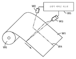
도 1은 교정 시스템의 개략도.
도 2는 정량적 이미징(imaging) 시스템을 구성하는 기능 모듈들의 다이어그램.
도 3은 웨브 검사 시스템을 교정하는 데 사용될 수 있는 상위 공정(high-level process)을 예시하는 플로우차트.
도 4는 웨브 횡단(cross-web) 이송 장치에 장착된 센서를 갖는 교정 시스템의 개략도.
도 5는 웨브 검사 시스템이 2개의 라인-스캔(line-scan) 카메라를 포함하는 교정 시스템의 개략도.1 is a schematic diagram of a calibration system.
2 is a diagram of the functional modules that make up a quantitative imaging system.
3 is a flowchart illustrating a high-level process that can be used to calibrate a web inspection system.
4 is a schematic representation of a calibration system with sensors mounted to a cross-web transport device.
5 is a schematic diagram of a calibration system in which the web inspection system includes two line-scan cameras.
웨브 검사 시스템은 정량적 실시 형태 및 정성적 실시 형태로 이루어져 있다. 정량적 검사 시스템은 기지의 표준에 대해 교정된 단위, 예를 들어 공학 단위의 웨브 특성에 관한 검사 정보를 산출한다. 이는 시간의 경과에 따른 웨브 특성의 상대적 변화에 중점을 두고 있는 정성적 검사 시스템과 대조된다. 정성적 검사 시스템은 특정의 공정 결함(예를 들어, 채터(chatter), 다이 라인(die line), 얼룩(mottle), 및 기타 전형적인 불균일)을 나타내는 신호 패턴을 인식하는 데 충분할 수 있다. 그러나, 정성적 검사 시스템은 절대적인 목표 수준 또는 교정 절차에 의존하지 않기 때문에, 정성적 검사 시스템은 웨브 공정이 제어 중인지 여부, 또는 공정에 대한 변화가 하나의 실행으로부터 다음 실행까지 웨브의 불균일 수준을 감소시켰는지 여부를 추적하기 위해 조작자에 의해 사용될 수 있는 재현가능한 측정기준(또는 측정기준 세트)을 산출하지 않는다.The web inspection system consists of quantitative and qualitative embodiments. The quantitative inspection system yields inspection information regarding web properties of units calibrated against known standards, for example engineering units. This contrasts with a qualitative inspection system that focuses on the relative changes in web properties over time. Qualitative inspection systems may be sufficient to recognize signal patterns that exhibit certain process defects (eg, chatter, die lines, mottles, and other typical non-uniformities). However, since the qualitative inspection system does not rely on absolute target levels or calibration procedures, the qualitative inspection system reduces the level of non-uniformity of the web from one run to the next, whether the web process is under control, or changes to the process. It does not yield reproducible metrics (or sets of metrics) that can be used by the operator to track whether or not the device has been used.
웨브-기반 제품을 검사하는 데 사용되는 센서 및 이미징 시스템은 주기적으로 교정되어야 한다. 특정의 교정 스케줄은 검사되는 웨브의 유형, 및 검사를 받는 관심대상의 웨브 특성과 같은 것들에 의존한다. 부가적으로, 동작 환경에서의 환경 조건(온도, 습도, 먼지 수준 등등) 및 생산과 유지보수 스케줄은 검사 시스템이 교정 상태로부터 벗어나게 할 수 있고, 따라서 수일 마다, 수시간 마다, 또는 가능하게는 훨씬 더 자주 교정을 필요로 하게 할 수 있다. 웨브 검사용 광학 감지 장비를 교정하는 접근법은 일반적으로 몇몇 카테고리들 중 하나 이상에 속한다.Sensors and imaging systems used to inspect web-based products must be calibrated periodically. The particular calibration schedule depends on things such as the type of web being inspected and the web characteristics of interest being inspected. In addition, environmental conditions (temperature, humidity, dust levels, etc.) and production and maintenance schedules in the operating environment can cause the inspection system to be out of calibration, and therefore every few days, hours, or possibly even more. You may need to calibrate more often. Approaches to calibrating optical sensing equipment for web inspection generally fall into one or more of several categories.
첫째, 웨브 검사 시스템을 교정하는 "오프라인" 접근법은 그 시스템이 기지의 샘플 또는 기지의 샘플 세트에 노출될 때 웨브 검사 시스템에 의해 생성된 신호(광학 신호 등등)를 기록하는 것을 수반한다. 광학 검사 시스템의 경우에, 이는 종종 일련의 샘플을 검사 시스템의 광 경로 또는 경로들 내에, 가능하게는 다수의 위치에 배치함으로써 행해진다. 이러한 오프라인 접근법은 웨브에 의해 보통 점유되는 위치로 샘플들이 배치되면서 정상적인 웨브 처리 또는 생산이 중단될 것을 필요로 한다. 이러한 오프라인 접근법에 대한 변형은 웨브 검사 시스템(조명 장치를 포함함)을, 일반적으로 라인에 인접하고 웨브 경로에서 벗어난 오프-웨브 위치(off-web position)로 이동시키는 것이며, 여기서 표준 샘플 또는 샘플들과 연관된 감지 응답이 기록될 수 있고 따라서 웨브 검사 시스템이 교정될 수 있다. 교정 후에, 웨브 검사 시스템은 그의 웨브-검사 위치로 복귀된다. 오프라인인 경우 검사 시스템이 교정되는 동안, 웨브 처리가 진행될 수 있지만, 제2 검사 시스템(고가임)이 없는 경우, 그러한 처리가 제어 내에 있지 않을 수 있다.First, an "offline" approach to calibrating a web inspection system involves recording signals (optical signals, etc.) generated by the web inspection system when the system is exposed to a known sample or a set of known samples. In the case of an optical inspection system, this is often done by placing a series of samples in the optical path or paths of the inspection system, possibly in multiple locations. This off-line approach requires normal web processing or production to cease as samples are placed in positions normally occupied by the web. A variation on this off-line approach is to move the web inspection system (including the lighting device) to an off-web position, generally adjacent to the line and off the web path, where a standard sample or samples The sensing response associated with the can be recorded and the web inspection system can be calibrated. After calibration, the web inspection system is returned to its web-inspection position. While offline, the web processing may proceed while the inspection system is being calibrated, but if there is no second inspection system (expensive), such processing may not be in control.
제2 접근법은 정상적인 웨브가 생산되고 있는 동안에, 즉 비록 아직 알려지지 않은 특성들을 갖긴 하지만 생산된 상태 그대로의 웨브를 사용하여 교정 데이터를 획득하려고 시도한다. 이를 행하기 위해, 검사 시스템은 그 위치가 표시되어 있거나 달리 웨브 취급 시스템에 알려진 웨브의 제1 섹션으로부터의 데이터를 기록한다. 웨브의 제1 섹션이 권취기(winder)에 도달할 때, 제1 섹션은 보통 "롤 단부(end-of-roll)" 샘플로서 웨브의 나머지로부터 절단되고, 품질 관리 연구실로 보내진다. 샘플이 검사 스테이션을 통과할 때 검사 시스템에 의해 저장된 데이터와 샘플 상의 위치들이 정렬되게 하는 정확한 위치 정보가 이용가능하다면, 검사 시스템에 교정 데이터를 제공하는 데 오프라인 품질 관리 기기가 사용될 수 있다. 이 접근법은 자원 집약적이고, 양호한 데이터를 얻기 위해 샘플 정렬에 신중한 주의를 필요로 하며 또한 샘플이 검사 스테이션을 처음으로 통과할 때와 교정이 이용가능하게 될 때 사이에 상당한 시간 지연을 겪는다.The second approach attempts to obtain calibration data while the normal web is being produced, i.e., using the web as it is, although it has properties that are not yet known. To do this, the inspection system records data from the first section of the web whose location is indicated or otherwise known to the web handling system. When the first section of the web reaches the winder, the first section is usually cut from the rest of the web as a "end-of-roll" sample and sent to the quality control lab. An offline quality control device can be used to provide calibration data to the inspection system if accurate location information is available that allows the locations on the sample to be aligned with the data stored by the inspection system as the sample passes through the inspection station. This approach is resource intensive and requires careful attention to sample alignment to obtain good data and also suffers a significant time delay between when the sample first passes the test station and when calibration is available.
제3 접근법은 상기 2가지 접근법의 몇몇 조합을 포함한다. 예를 들어, 기지의 샘플이 정상적인 웨브 경로의 가장자리의 외부에 그러나 검사 시스템이 볼 수 있는 영역 내에 배치될 수 있다. 이는 제품이 여전히 지나가는 동안 최외측 센서 요소들에 진행하는 교정 데이터를 제공한다. 그러나, 그 특성들이 알려지지 않은 정상적인 웨브에 걸쳐 웨브 검사 시스템 센서(들)에 교정을 전달하는 것은 내부 센서 요소들의 응답과 외부 센서 요소들의 응답 사이의 관계에 대한 지식을 필요로 하며, 이들 응답은 항상 서로에 대해 고정된 채로 있어야 한다. 다른 예에서, 교정 샘플이 검사 시스템의 시야의 다양한 부분들에 노출되고, 따라서 웨브의 미지의 특성들에 추가적인 기지의 오프셋을 부가한다. 이는 교정 동안에 웨브의 통계적 변동에 얼마간의 제한을 두며, 또한 검사 시스템이 동작할 필요가 있을 수 있는 범위를 변화시킨다.The third approach involves some combination of the two approaches. For example, the known sample may be placed outside the edge of the normal web path but within the area visible to the inspection system. This provides calibration data that proceeds to the outermost sensor elements while the product is still passing. However, transferring calibration to the web inspection system sensor (s) over a normal web whose characteristics are unknown requires knowledge of the relationship between the response of the internal sensor elements and the response of the external sensor elements, and these responses are always It must remain fixed with respect to each other. In another example, a calibration sample is exposed to various portions of the field of view of the inspection system, thus adding an additional known offset to the unknown properties of the web. This places some limits on the statistical variation of the web during calibration and also changes the range in which the inspection system may need to operate.
전술된 접근법들에 필요한 검사 시스템의 다중 점 교정(multiple point calibration)은 지루하고, 비교적 많은 수의 사람 조작자, 자동화된 교정 시스템에 대한 많은 자본 투자, 또는 이 둘의 조합을 필요로 할 수 있다. 또한, 검사 시스템을 구성하는 구성요소들(예를 들어, 카메라에 조명을 제공하는 광원의 강도 분포, 또는 레이저 스캐너에서의 광원과 수광 광학계 사이의 정렬)에 대한 변화가 추가적인 교정(들)을 필요로 한다.Multiple point calibration of the inspection system required for the aforementioned approaches can be tedious and require a relatively large number of human operators, a large capital investment in an automated calibration system, or a combination of both. In addition, changes to the components constituting the inspection system (eg, the intensity distribution of the light source providing illumination to the camera, or the alignment between the light source and the light receiving optics in the laser scanner) require additional calibration (s). Shall be.
도 1은 웨브 취급 시스템(W6) 상의 교정 시스템의 일 실시 형태의 개략도를 도시한다. 웨브 취급 시스템(W6)은 웨브(W1)를 제조, 변환, 처리 또는 검사하는 데 사용되는 임의의 웨브 취급 시스템일 수 있다. 웨브(W1)는 자동화된 검사를 받을 수 있는, 두께보다 실질적으로 폭이 더 큰 임의의 재료일 수 있다. 예를 들어, 웨브(W1)는 광학 필름, 배터리 멤브레인(battery membrane) 재료, 종이, 일종의 직조(woven) 재료, 일종의 부직 재료, 연마재, 미세구조화된(micro-structured) 필름, 다층 필름, 복합 필름, 인쇄되고 패턴화된 웨브, 포일(foil), 또는 (압연 강재와 같은) 시트 물품일 수 있다. 웨브(W1)는 습윤 코팅과 같은 하나 이상의 코팅을 가질 수 있다. 부가적으로, 웨브(W1)는 웨브를 형성하도록 성형되거나 웨브 상에 성형된 조각들의 웨브일 수 있다.1 shows a schematic diagram of one embodiment of a calibration system on web handling system W6. Web handling system W6 may be any web handling system used to manufacture, convert, process, or inspect web W1. Web W1 can be any material that is substantially larger in width than can be subjected to automated inspection. For example, the web W1 may be an optical film, a battery membrane material, paper, a kind of woven material, a kind of nonwoven material, an abrasive, a micro-structured film, a multilayer film, a composite film. , Printed and patterned webs, foils, or sheet articles (such as rolled steel). Web W1 may have one or more coatings, such as a wet coating. Additionally, web W1 may be a web of pieces molded to form a web or molded on a web.
웨브(W1)는, 가능하게는 제조 또는 변환 공정의 일부로서, 좌측으로부터 우측으로 이동한다. 센서(W2)는 웨브 검사 시스템(W3)으로부터 웨브 상류측에 위치된 것으로 도시되어 있지만, 웨브 검사 시스템(W3)의 웨브 하류측에 또한 위치될 수 있다. 일 실시 형태에서, 센서(W2)는 심지어 웨브 검사 시스템(W3)과 동일한 웨브 영역으로부터 신호를 수신하도록 위치될 수 있다. 그러한 실시 형태에서, (센서(W2) 및 웨브 검사 시스템(W3) 둘 모두가 광 신호에 기초한다면) 웨브 영역으로부터 나오는 신호에 대해 하나 이상의 빔스플리터(beamsplitter)가 사용될 수 있다.Web W1 moves from left to right, possibly as part of a manufacturing or conversion process. The sensor W2 is shown positioned upstream from the web inspection system W3, but may also be located downstream of the web of the web inspection system W3. In one embodiment, sensor W2 may even be positioned to receive signals from the same web area as web inspection system W3. In such embodiments, one or more beamsplitters may be used for the signal coming from the web region (if both sensor W2 and web inspection system W3 are based on an optical signal).
센서(W2)는, 일 실시 형태에서, 웨브(W1)의 단일 레인(lane) W4로부터 나오는 검사 신호를 수신하고 이어서 이러한 응답을 나타내는 신호를 발생하도록 구성된 단일 판독 센서이다. 센서(W2)는 임의의 유형의 센서일 수 있는데, 예를 들어 센서는 광학 센서(예를 들어, 가시광, 자외선, 적외선, 또는 근적외선에 민감하거나, 테라헤르쯔(terahertz) 이미징 기법을 채용함), 또는 일부 유형의 전자기 방사선을 수신하도록 구성된 센서, 또는 음파를 수신하도록 구성된 센서일 수 있다. 센서(W2)는 웨브(W1)의 특성을 교정된 단위로 정확하게 측정하도록 교정된다. 센서(W2)가 단일 점 센서(point sensor)일 것이 필요하지는 않지만, 후술되는 웨브 검사 시스템으로의 교정 전달은 단일 데이터 스트림(stream)을 사용한다. 센서(W2)가 단일 점 센서가 아닌 경우, 센서(W2)를 구성하는 수 개의 인접한 감지 요소들(카메라 픽셀, 용량성 감지 요소 등등)로부터의 신호를 평균하여 단일 데이터 스트림을 얻음으로써 단일 데이터 스트림이 제공될 수 있다. 센서(W2)를 구성하는 감지 요소들의 개수에 대한 엄격한 제한은 없지만, 센서(W2)에 있는 요소들이 많을수록, 그 요소들 모두가 서로에 대하여 동일한 응답에 대해 교정되도록 하는 것이 더 어려울 수 있다.Sensor W2 is, in one embodiment, a single read sensor configured to receive a test signal from a single lane W4 of web W1 and then generate a signal indicative of this response. The sensor W2 can be any type of sensor, for example the sensor is an optical sensor (eg, sensitive to visible light, ultraviolet light, infrared light, or near infrared, or employs terahertz imaging techniques), Or a sensor configured to receive some type of electromagnetic radiation, or a sensor configured to receive sound waves. Sensor W2 is calibrated to accurately measure the properties of web W1 in calibrated units. It is not necessary for sensor W2 to be a single point sensor, but calibration delivery to the web inspection system described below uses a single data stream. If the sensor W2 is not a single point sensor, a single data stream is obtained by averaging signals from several adjacent sensing elements (camera pixels, capacitive sensing elements, etc.) that make up the sensor W2 to obtain a single data stream. This may be provided. There is no strict limit on the number of sensing elements that make up sensor W2, but the more elements there are in sensor W2, the more difficult it is to ensure that all of them are corrected for the same response to each other.
웨브 검사 시스템(W3)은, 일 실시 형태에서, 단일 출력 센서(W2)와 동일한 단일 레인 W4뿐만 아니라 레인 W4 이외의 레인과 연관된 검사 신호를 적어도 수신하는 라인-스캔 카메라이다. 라인-스캔 카메라는 비교적 저렴하고 어디에나 있지만, 본 명세서에 기술된 동일하거나 유사한 교정 기법 및 시스템은 다른 유형의 검사 시스템에 적응할 수 있다. 예를 들어, 라인-스캔 카메라 이외에, 웨브 검사 시스템(W3)은 또한 레이저 스캐너, 시간-지연 적분 카메라, 영역 스캔 카메라, 기타 어레이 센서, 또는 이들 시스템의 일부 조합을 포함할 수 있다. 웨브 검사 시스템(W3)은 전체 폭보다 작은 웨브(W1)의 폭으로부터 신호를 수신할 수 있다.Web inspection system W3 is, in one embodiment, a line-scan camera that receives at least inspection signals associated with lanes other than lane W4, as well as the same single lane W4 as single output sensor W2. While line-scan cameras are relatively inexpensive and everywhere, the same or similar calibration techniques and systems described herein can be adapted to other types of inspection systems. For example, in addition to a line-scan camera, the web inspection system W3 may also include a laser scanner, time-delay integral camera, area scan camera, other array sensor, or some combination of these systems. Web inspection system W3 may receive a signal from a width of web W1 that is less than the full width.
센서(W2)는 기지의 표준과 비교하여 주기적으로 교정된다. 센서(W2) 교정의 타이밍은 교정으로부터 벗어나 드리프트(drift)하는 센서의 특성 및 특정 웨브 처리 환경에 요구되는 허용오차에 의존한다. 예를 들어, 센서(W2)로서 사용되는 광학 밀도 게이지는 특정 파장 대역 내에서 웨브의 광 투과를 측정하도록 구성될 수 있지만, 광원이 노후화됨에 따라, 그의 스펙트럼 출력 및/또는 파워 수준이 변하여 센서로부터 나오는 데이터의 정확성에 영향을 줄 수도 있다. 그러한 센서의 응답은 그러한 드리프트를 보정하기 위해 기지의 표준 또는 표준 세트를 사용하여 주기적으로 확인될 수 있다.Sensor W2 is periodically calibrated against known standards. The timing of the sensor W2 calibration depends on the characteristics of the sensor drift away from the calibration and the tolerances required for the particular web processing environment. For example, the optical density gauge used as the sensor W2 can be configured to measure the light transmission of the web within a particular wavelength band, but as the light source ages, its spectral output and / or power level changes from the sensor. It may also affect the accuracy of the data coming out. The response of such a sensor can be checked periodically using known standards or sets of standards to compensate for such drift.
센서(W2)의 교정은, 라인 스캔 카메라와 같은 웨브 검사 시스템의 교정과 비교할 때, 오히려 사소한 사항이며, 일 실시 형태에서는 기지의 표준 또는 표준 세트로부터 신호를 수신하기 위해 단일 출력 센서를 오프라인으로 변경시킴으로써 달성될 수 있다. 대안적으로, 센서(W2)는 제조 라인 부근에 위치된 품질 관리 연구실에서 기지의 기법들을 사용하여 교정될 수 있다. 다른 대안으로서, 센서(W2)가 교정을 위해 제조자 또는 판매자 연구실로 또는 심지어 미국 국립표준기술연구소(National Institute of Standards and Technology)와 같은 국립 연구실로 보내질 수 있다. 센서(W2)의 교정 동안에, 웨브 검사 시스템(W3)은 웨브를 그의 이전에 교정된 상태를 사용하여 계속 검사할 수 있다. 일부 경우들에서, 임의의 주어진 때에, 적어도 하나의 단일 출력 센서가 레인 W4에서 통과하는 웨브로부터 신호를 온라인으로 수신하여, 교정된 신호가 적어도 하나의 단일 출력 센서로부터 수신되는 반면 다른 단일 출력 센서(들) 중 임의의 것이 오프라인으로 교정되도록(그리고 역으로도 성립함), 복수의(2개, 3개 또는 심지어 그 이상의) 단일 출력 센서들을 갖는 웨브 취급 시스템(W6)을 구성하는 것이 바람직할 수 있다.Calibration of sensor W2 is rather trivial when compared to calibration of web inspection systems such as line scan cameras, and in one embodiment changes a single output sensor offline to receive signals from known standards or sets of standards. Can be achieved by Alternatively, sensor W2 can be calibrated using known techniques in a quality control lab located near the manufacturing line. Alternatively, the sensor W2 can be sent to a manufacturer or vendor laboratory for calibration or even to a national laboratory such as the National Institute of Standards and Technology. During calibration of sensor W2, web inspection system W3 can continue to inspect the web using its previously calibrated state. In some cases, at any given time, at least one single output sensor receives a signal online from the web passing in lane W4 such that a calibrated signal is received from at least one single output sensor while the other single output sensor ( It may be desirable to construct a web handling system W6 with a plurality of (two, three or even more) single output sensors such that any of the two) are calibrated offline (and vice versa). have.
센서(W2)는, 일 실시 형태에서, 웨브 검사 시스템(W3)과 동일한 특성을 측정하도록 구성된다. 예를 들어, 센서(W2) 및 웨브 검사 시스템(W3) 둘 모두는, 일 실시 형태에서, 사람의 눈에 보이는 범위 내의 검사 신호(이 경우에, 광)에 응답하도록 구성될 수 있다. 그러나, 대안적으로, 웨브 검사 시스템(W3)은 센서(W2)에 의해 측정되는 것과는 상이하지만 그와 강하게 상관되는 특성을 측정하도록 구성될 수 있다. 강하게 상관된 특성의 일례는 센서(W2)가 초음파 변환기(transducer)를 통해 웨브의 두께를 측정하는 경우이고, 웨브 검사 시스템(W3)은 사람이 볼 수 있는 스펙트럼 내의 광에 민감한 라인 스캔 카메라이다. 사람이 볼 수 있는 스펙트럼 내의 광과 강하게 상관된 웨브 특성의 다른 일례는, 적어도 일부 경우들에서, 위에서 논의된 열 전도율이다.The sensor W2, in one embodiment, is configured to measure the same characteristics as the web inspection system W3. For example, both sensor W2 and web inspection system W3 may be configured to respond to an inspection signal (in this case, light) within the human visible range, in one embodiment. Alternatively, however, the web inspection system W3 may be configured to measure a characteristic that is different from, but strongly correlated with, that measured by the sensor W2. One example of strongly correlated properties is when the sensor W2 measures the thickness of the web via an ultrasonic transducer, and the web inspection system W3 is a line scan camera that is sensitive to light in the human visible spectrum. Another example of a web characteristic that is strongly correlated with light in the human visible spectrum is the thermal conductivity discussed above, at least in some cases.
정량적 이미징 시스템(W5)은 센서(W2) 및 웨브 검사 시스템(W3)으로부터 입력을 수신하고 입력을 분석하여 웨브 검사 시스템(W3)에 대한 교정 모델을 적용하거나 일부 실시 형태에서 상기 교정 모델을 결정하는, 중앙 처리 유닛 및 메모리를 갖는 특수 용도 또는 범용 컴퓨터일 수 있다. 교정 모델은 웨브 검사 시스템(W3)으로부터의 출력 신호를 원시 데이터(raw data)로부터 교정된 단위로 변환하는 데 사용되는 수학적 관계를 정의하는 하나 이상의 수치 값 또는 알고리듬이다. 본 명세서에서 기술될 2가지 일반적인 교정 모델이 있다. "센서 대 검사 시스템 교정 모델"인 제1 교정 모델은 센서(W3)와 센서(W3)와 동일한 레인 W4와 연관된 검사 시스템(W3)의 일부분 사이의 수학적 관계를 정의한다. "웨브 횡단 교정 모델"인 제2 교정 모델은 검사 시스템(W3)의 웨브 횡단 시야를 구성하는 레인들 사이의 수학적 관계를 정의한다.The quantitative imaging system W5 receives inputs from the sensor W2 and the web inspection system W3 and analyzes the inputs to apply a calibration model for the web inspection system W3 or in some embodiments determine the calibration model. It may be a special purpose or general purpose computer having a central processing unit and a memory. The calibration model is one or more numerical values or algorithms that define the mathematical relationships used to convert the output signal from web inspection system W3 from raw data to calibrated units. There are two general calibration models to be described herein. The first calibration model, which is a "sensor to inspection system calibration model", defines a mathematical relationship between sensor W3 and a portion of inspection system W3 associated with lane W4 identical to sensor W3. The second calibration model, which is the "web cross calibration model", defines the mathematical relationship between the lanes that make up the web cross view of the inspection system W3.
정량적 이미징 시스템(W5)은 레인 W4와 연관된 데이터 세트(센서 대 검사 시스템 교정 모델을 통해 점 센서(W2)에 대해 교정됨) 및 레인 W4 이외의 하나 이상의 레인과 연관된 데이터 세트뿐만 아니라 검사 시스템의 웨브 횡단 신호 프로파일을 기술하는 데이터를 처리함으로써 웨브 횡단 교정 모델을 결정한다.The quantitative imaging system W5 is a web of inspection systems as well as a data set associated with lane W4 (calibrated for point sensor W2 via a sensor to inspection system calibration model) and one or more lanes other than lane W4. A web cross calibration model is determined by processing the data describing the cross signal profile.
정량적 이미징 시스템(W5)이 도 1에서 단일 시스템으로서 도시되어 있지만, 대안적인 실시 형태에서, 서로 네트워크로 연결되어 있거나 독립적으로 있는, 본 명세서에 기술된 교정 기법을 지원하는 다양한 소프트웨어 알고리듬을 실행하는 복수의 컴퓨터로 구성될 수 있다.Although the quantitative imaging system W5 is shown as a single system in FIG. 1, in alternative embodiments a plurality of executing various software algorithms that support the calibration techniques described herein, networked or independent of one another. It can be configured as a computer.
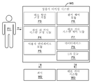
도 2는, 예시적인 일 실시 형태에서, 정량적 이미징 시스템(W5)을 구성하는 기능 모듈을 나타낸 다이어그램이다. 도 2는 기능 모듈들의 개별 세트에 대해 기술되어 있지만, 숙련자는 이러한 설명이 단지 예시적인 목적을 위한 것이며 동일한 또는 유사한 기능을 갖는 시스템이 무수한 방식으로 구성될 수 있다는 것을 이해할 것이다. 도 2에 예시된 기능 모듈들 각각은 다른 모듈들 중 임의의 것과 통신할 수 있고, 모듈들 중 임의의 것은 하드웨어로 또는 소프트웨어로 또는 이들의 몇몇 조합으로 구현될 수 있다. 사용자(P1)는 웨브 검사 시스템(W5)의 임의의 사용자이다. 사용자(P1)는 웨브(W1)에 대한 품질 관리를 책임지고 있는 사람 조작자일 수 있다. 사용자(P1)는 주로 키보드, 마우스, 및 몇몇 종류의 디스플레이(이들 중 어느 것도 도 2에 도시되어 있지 않음)를 통해 정량적 이미징 시스템(W5)과 상호작용한다. 사용자 인터페이스 모듈(P5)은, 사용자(P1)가 정량적 이미징 시스템(W5)에 정보를 제공하기도 하고 정량적 이미징 시스템(W5)으로부터 정보를 수신할 수도 있도록, 디스플레이 상에 그래픽 사용자 인터페이스 또는 명령행(command-line) 유형 인터페이스를 생성할 수 있다. 일 실시 형태에서, 사용자 인터페이스 모듈(P5)은 미국 워싱턴주 레드몬드 소재의 마이크로소프트 코포레이션(Microsoft Corporation)에 의해 상표명 "윈도우즈(Windows)"로 시판되는 것과 같은 운영 체제에 의해 제공된 기능을 호출함으로써 디스플레이 상에 창(window)을 생성한다. 기타 운영 체제들이 유사하게 사용될 수 있다. 사용자 인터페이스 모듈(P5)은 이어서 데이터 및 명령을 제공하고 다른 기능 모듈들로부터 데이터 및 명령을 수신한다. 자동화된 웨브 공정 제어 또는 웨브 모니터링 시스템에 대한 추가의 인터페이스(도 2에 도시되지 않음)가 있을 수 있다.2 is a diagram illustrating the functional modules that make up the quantitative imaging system W5, in one exemplary embodiment. Although FIG. 2 is described for a separate set of functional modules, the skilled person will understand that this description is for illustrative purposes only and that systems having the same or similar functionality may be configured in a myriad of ways. Each of the functional modules illustrated in FIG. 2 may be in communication with any of the other modules, and any of the modules may be implemented in hardware or in software or in some combination thereof. User P1 is any user of web inspection system W5. User P1 may be a human operator in charge of quality control for web W1. The user P1 interacts with the quantitative imaging system W5 primarily via a keyboard, mouse, and some kind of display (neither of which is shown in FIG. 2). The user interface module P5 is a graphical user interface or command line on the display such that the user P1 may provide information to and receive information from the quantitative imaging system W5. -line) type interface can be created. In one embodiment, the user interface module P5 displays on the display by invoking a function provided by the operating system such as that sold under the trade name "Windows" by Microsoft Corporation, Redmond, Washington. Create a window in. Other operating systems can be used similarly. The user interface module P5 then provides data and commands and receives data and commands from other functional modules. There may be additional interfaces (not shown in FIG. 2) to the automated web process control or web monitoring system.
I/O 모듈(P9)은 센서(W2) 및 웨브 검사 시스템(W3)과 인터페이싱한다. I/O 모듈(P9)은 센서(W2) 및 웨브 검사 시스템(W3)으로부터 데이터 스트림을 수신한다. 예시적인 일 실시 형태에서, 정량적 이미징 시스템(W5)의 특정 구현에 따라, I/O 모듈(P9)은 또한 명령 및 제어 정보를 센서(W2) 및/또는 웨브 검사 시스템(W3)에 제공한다. 예를 들어, 본 개시 내용의 다른 곳에서, 센서(W2)가 웨브를 횡단하여 이동할 수 있도록 센서(W2)가 부착되는 웨브 횡단 이송 장치의 일 실시 형태가 기술된다. I/O 모듈(P9)은, 그러한 실시 형태에서, 그러한 웨브 횡단 이동을 지시하는 제어 신호를 제공할 수 있다. 또한, I/O 모듈(P9)은, 일반적으로 센서(W2) 또는 웨브 검사 시스템(W3)을 제어하기 위해, 다른 정보를 제공할 수 있다. I/O 모듈(P9)에 의해 수신되는 입력은 다른 모듈들에 직접 제공될 수 있거나 후속적인 분석을 위해 데이터베이스(P8)에 저장될 수 있다.I / O module P9 interfaces with sensor W2 and web inspection system W3. I / O module P9 receives data streams from sensor W2 and web inspection system W3. In one exemplary embodiment, according to a particular implementation of the quantitative imaging system W5, the I / O module P9 also provides command and control information to the sensor W2 and / or the web inspection system W3. For example, elsewhere in the present disclosure, one embodiment of a web traverse transfer device to which the sensor W2 is attached is described so that the sensor W2 can move across the web. I / O module P9 may, in such embodiments, provide a control signal indicative of such web cross motion. In addition, I / O module P9 may generally provide other information to control sensor W2 or web inspection system W3. The input received by I / O module P9 may be provided directly to other modules or may be stored in database P8 for subsequent analysis.
데이터베이스(P8)는 랜덤 액세스 메모리 또는 하드 디스크 드라이브 또는 이들의 몇몇 조합과 같은 컴퓨터 메모리에 구현되는 데이터 저장소이다. 이는 단순히, 상표명 "SQL 서버(Server)"로 미국 워싱턴주 레드몬드 소재의 마이크로소프트 코포레이션에 의해 시판되는 것과 같은 데이터베이스, 플랫 파일(flat file), 또는 컴퓨터 메모리일 수 있다. 데이터베이스(P8)는 정량적 이미징 시스템(W5)을 구성하는 기능 모듈들 중 임의의 것의 데이터 저장 요구를 다룬다. 센서(W2) 및 웨브 검사 시스템(W3)으로부터 나오는 데이터 스트림은 데이터베이스(P8)에 저장될 수 있을 뿐만 아니라 교정 모델을 구성하는 데이터일 수 있다.Database P8 is a data store implemented in computer memory, such as random access memory or hard disk drive or some combination thereof. It may simply be a database, flat file, or computer memory, such as the one sold by Microsoft Corporation of Redmond, Washington, under the trade name “SQL Server”. The database P8 handles the data storage needs of any of the functional modules that make up the quantitative imaging system W5. The data streams coming from the sensor W2 and the web inspection system W3 can be stored in the database P8 as well as the data making up the calibration model.
웨브 검사 시스템 제어 모듈(P7)은 명령 및 제어 신호를 I/O 모듈(P9)을 통해 웨브 검사 시스템(W3)에 제공한다. 웨브 검사 시스템 제어 모듈(P7)에 의해 지원되는 특정 기능은 대체로 구현을 위해 선택된 특정 웨브 검사 시스템(W3)에 의해 제공되는 명령 및 제어 인터페이스에 의존한다. 예를 들어, 웨브 검사 시스템(W3)을 구성할 수 있는 몇몇 라인 스캔 카메라는 특정 기능 세트를 지원하도록 응용 프로그래밍 인터페이스를 가지며, 그러한 기능은 도 2에서 웨브 검사 시스템 제어 모듈(P7) 내에 존재할 것이다. 웨브 검사 시스템(W3)이 변환될 필요가 있는 출력(예를 들어, 단위로 변환될 필요가 있는 원시 전압(raw voltage))을 갖는 경우, 웨브 검사 시스템 제어 모듈(P7) 내에 변환 수단이 구현된다.The web inspection system control module P7 provides command and control signals to the web inspection system W3 via the I / O module P9. The specific functionality supported by the web inspection system control module P7 relies largely on the command and control interface provided by the particular web inspection system W3 selected for implementation. For example, some line scan cameras that can configure the web inspection system W3 have an application programming interface to support a particular set of functions, such functionality will be present in the web inspection system control module P7 in FIG. When the web inspection system W3 has an output that needs to be converted (for example, a raw voltage that needs to be converted into units), conversion means are implemented in the web inspection system control module P7. .
센서 제어 모듈(P6)과 센서 제어 모듈(P6)간의 관계는, 필요한 변경을 가하여, 웨브 검사 시스템 제어 모듈(P7)과 웨브 검사 시스템(W3)간의 관계와 같다.The relationship between the sensor control module P6 and the sensor control module P6 is the same as that between the web inspection system control module P7 and the web inspection system W3 with the necessary changes.
센서 대 검사 시스템 교정 모듈(P4)은 웨브 검사 시스템(W3) 및 센서(W2)로부터의 데이터(I/O 모듈(P9)을 통해 제공되고 가능하게는 데이터베이스(P8)에 저장되어 있음)를 분석하고, 센서(W2)와 동일한 웨브 횡단 레인과 연관된 검사 시스템(W3)으로부터의 출력이 센서(W2)의 출력의 교정된 단위로 변환되도록 센서 대 검사 시스템 교정 모델을 확립한다. 이 변환의 예들이 이하에서 제공된다.Sensor to inspection system calibration module P4 analyzes data from web inspection system W3 and sensor W2 (provided via I / O module P9 and possibly stored in database P8). And establish a sensor to inspection system calibration model such that the output from inspection system W3 associated with the same web crossing lane as sensor W2 is converted into a calibrated unit of the output of sensor W2. Examples of this conversion are provided below.
웨브 횡단 교정 모듈(P3)은, 필요한 경우, 센서 대 검사 시스템 교정 모듈(P4)에 의해 제공되는 교정 모델을 결정하고 이를 웨브 검사 시스템(W3)에 의해 검사되는 웨브(W1)의 다른 레인들에 적용하여, 검사 시스템(W3)의 시야를 구성하는 모든 레인들로부터의 데이터가 레인(W3)에 대해 교정되게 한다. 이러한 교정의 예들이 이하에서 제공된다.The web cross calibration module P3 determines, if necessary, the calibration model provided by the sensor to inspection system calibration module P4 and compares it to the other lanes of the web W1 inspected by the web inspection system W3. In this way, data from all the lanes making up the field of view of inspection system W3 is corrected for lane W3. Examples of such calibration are provided below.
도 2와 관련하여 기술되는 기능 모듈들은 그들의 일반적인 특성과 일치하는 추가 기능을 가질 수 있지만, 본 개시 내용에서는 언급되지 않았다. 도 2에 열거된 기능 모듈과 명시적으로 연관되지 않는 다른 곳에서 기술된 기능이 일반적으로 정량적 이미징 시스템(W5) 내에 존재한다. 예를 들어, 센서(W2) 및 웨브 검사 시스템(W3)으로부터 나오는 신호들의 정렬을 제공하는 기능이 일반적으로 정량적 이미징 시스템(W5) 내에 존재한다.The functional modules described in connection with FIG. 2 may have additional functionality consistent with their general characteristics, but are not mentioned in this disclosure. Functions described elsewhere not explicitly associated with the functional modules listed in FIG. 2 are generally present in the quantitative imaging system W5. For example, the function of providing alignment of signals from sensor W2 and web inspection system W3 is generally present in quantitative imaging system W5.
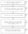
도 3은 도 W에 도시된 웨브 검사 시스템(W3)을 교정하는 데 사용될 수 있는 상위 공정을 예시하는 플로우차트이다. 이 예에서, 웨브 검사 시스템(W3)으로부터 웨브 상류측에 위치되고 웨브 라인의 특정 "레인"과 연관된 센서(W2)로부터 제1 신호 응답이 수신된다(F1). 도 F와 관련하여, 이 레인은 레인 X라고 불릴 것이다. 웨브 검사 시스템(W3)은 웨브의 전체 폭(또는 그의 일부 부분)을 검사(즉, 그로부터 신호를 수신)할 수 있지만, 적어도 레인 X를 검사한다(F2). 레인 X와 연관된 웨브 검사 시스템(W3)으로부터의 신호를 도 3의 목적을 위해 제2 신호 응답이라고 칭한다. 단일 출력 센서(W2) 및 웨브 검사 시스템(W3)의 레인-X 부분으로부터의 신호가 웨브(W1)의 동일한 영역을 나타내도록 제1 신호 응답이 제2 신호 응답과 동기화된다(F3). 단일 출력 센서(W2)와 웨브 검사 시스템(W3) 사이의 거리뿐만 아니라 웨브의 속도가 알려져 있는 경우, 동기화는 웨브(W1)를 따라 있는 점이 단일 출력 센서(W2)로부터 웨브 검사 시스템(W3)까지 가는 데 걸리는 시간을 결정함으로써 달성될 수 있다. 이러한 시간 지연은 시프트(shift)를 정의하는 데 사용될 수 있는데, 시프트는 이어서 센서(W2) 또는 웨브 검사 시스템(W3)으로부터 나오는 각각의 데이터 스트림에 적용되어서 데이터 스트림을 시간-동기화할 수 있다. 대안적으로, 센서(W2) 및 검사 어레이(W3)로부터 점들의 샘플링을 트리거링하기 위해 인코더(encoder)가 사용될 수 있다. 2개의 데이터 세트가 공간적으로 동기하도록, 인코더는 일정한 시간 간격보다는 웨브의 일정한 공간 간격으로 데이터 획득을 트리거링한다.FIG. 3 is a flowchart illustrating an upstream process that may be used to calibrate the web inspection system W3 shown in FIG. In this example, a first signal response is received F1 from a sensor W2 located upstream from the web inspection system W3 and associated with a particular "lane" of the web line. With regard to FIG. F, this lane will be called lane X. Web inspection system W3 may inspect (ie, receive signals from) the full width (or portion thereof) of the web, but at least inspect lane X (F2). The signal from web inspection system W3 associated with lane X is called a second signal response for the purposes of FIG. The first signal response is synchronized with the second signal response (F3) such that the signal from the lane-X portion of the single output sensor W2 and the web inspection system W3 represents the same area of the web W1. If the speed of the web as well as the distance between the single output sensor W2 and the web inspection system W3 is known, then the synchronization is along the web W1 from the single output sensor W2 to the web inspection system W3. This can be accomplished by determining the time it takes to go. This time delay can be used to define a shift, which can then be applied to each data stream coming from sensor W2 or web inspection system W3 to time-synchronize the data stream. Alternatively, an encoder can be used to trigger sampling of points from sensor W2 and check array W3. To ensure that the two data sets are spatially synchronized, the encoder triggers data acquisition at regular spatial intervals of the web rather than at regular time intervals.
센서와 웨브 검사 시스템 사이의 시간 지연을 측정(또는 계산)함으로써 시프트 값이 결정될 수 없을 때, 센서(W2) 및 웨브 검사 시스템(W3)로부터 나오는 데이터 스트림들을 시간-동기화시키는 데 필요한 시프트 값을 결정하는 데 상호 상관(cross-correlation)과 같은 데이터 분석 기법이 사용될 수 있다. 선형 상호 상관 방법이 데이터 세트들 사이의 오정렬을 판단하는 데 적절하도록 센서(W2) 및 웨브 검사 시스템(W3)의 레인-X 부분으로부터의 데이터 스트림이 유사한 경우 이 기법들이 가능하다. 일부 경우들에서, 레인-X에 대한 최상의 웨브 횡단 정렬을 찾기 위해 웨브 검사 시스템(W3)의 레인-X에 인접한 감지 요소들로부터의 데이터 스트림들이 센서(W2)로부터의 데이터 스트림과 비교된다. 웨브 조향 또는 잠재적으로는 심지어 웨브 연신 또는 수축으로 인해 최상의 상관을 갖는 웨브 검사 시스템(W3) 상의 웨브 횡단 공간 위치가 센서(W2)의 물리적 웨브 횡단 위치로부터 약간 변할 수 있다. 다른 경우들에서, 웨브 검사 시스템(W3)의 웨브 횡단 공간 분해능이 센서(W2)에 의해 감지되는 레인-X보다 더 미세한 스케일(scale)을 갖는 경우, 상호 상관이 수행되기 전에 레인-X에 있는 재료를 더 양호하게 반영하도록 웨브 검사 시스템(W3)의 수 개의 인접한 요소들로부터의 신호 출력들이 조합될 수 있다.Determine the shift value needed to time-synchronize the data streams coming from sensor W2 and web inspection system W3 when the shift value cannot be determined by measuring (or calculating) the time delay between the sensor and the web inspection system. Data analysis techniques such as cross-correlation can be used. These techniques are possible if the data streams from the lane-X portion of the sensor W2 and the web inspection system W3 are similar so that the linear cross correlation method is suitable for determining misalignment between data sets. In some cases, the data streams from the sensing elements adjacent to lane-X of web inspection system W3 are compared with the data stream from sensor W2 to find the best web cross alignment for lane-X. The web traversal space position on the web inspection system W3 with the best correlation due to web steering or potentially even web stretching or contraction may vary slightly from the physical web traverse position of the sensor W2. In other cases, if the cross-sectional spatial resolution of the web inspection system W3 has a finer scale than Lane-X sensed by the sensor W2, the cross-correlation before Signal outputs from several adjacent elements of the web inspection system W3 can be combined to better reflect the material.
소정 실시 형태들에서, 특히 센서들의 응답 함수에 대해 수학적 모델이 존재하는 경우에, 데이터 세트들 사이의 선형 관계를 획득하기 위해 상호 상관 이전에 변수 변환을 적용하는 것이 유리할 수 있다. 데이터 세트들 사이에 미지의, 가능하게는 비선형인 관계가 존재하는 다른 실시 형태들에서, 상호 정보와 같은 당업계에 공지된 보다 일반적인 유사성 측정기준을 채용할 수 있다. 이 절차는, 수 개의 시간 시프트 값들에 대해 유사성 측정기준이 연산되고 데이터 세트들이 유사성 측정기준을 최대화하는 시간 시프트를 선택함으로써 정렬된다는 점에서, 이하에서 기술되는 것과 유사하다.In certain embodiments, it may be advantageous to apply a variable transformation before cross correlation to obtain a linear relationship between data sets, especially where a mathematical model exists for the response function of the sensors. In other embodiments where there is an unknown, possibly nonlinear relationship between the data sets, more general similarity measures known in the art, such as mutual information, may be employed. This procedure is similar to that described below in that the similarity measure is computed for several time shift values and the data sets are sorted by selecting a time shift that maximizes the similarity measure.
이하의 방정식은 데이터 스트림들을 동기화시키기 위해 시프트 값을 수학적으로 결정하는 하나의 접근법을 나타낸다. 하기의 방정식은 비정규화된 상호 상관 및 뒤이은 선형 회귀(linear regression)에 대한 것이다.The equation below represents one approach to mathematically determining the shift value to synchronize the data streams. The following equations are for denormalized cross correlation and subsequent linear regression.
![]()
![]()
f는 특정의 웨브 횡단 위치 xi에서의 공학 단위의 교정된 단일 출력 센서 데이터의 벡터이고, g는 그 위치에서의 적절히 가중된 어레이 센서 데이터로부터 연산된 대응하는 벡터이다. 레인 W4와 연관된 웨브 검사 시스템(W3) 및 센서(W2)로부터의 데이터 세트들이 일정한 샘플링 거리에서 인코더 트리거 획득을 사용하여 시간에서 또는 공간에서 이산적으로 샘플링될 수 있다. 합계를 연산하기 위해 웨브의 유한한 웨브 하류측 섹션에 대해 샘플링의 결과가 정량적 이미징 시스템(W5)의 메모리와 같은 컴퓨터 메모리에 저장된다. 상호 상관을 수행하기 전에 데이터의 평균 중심을 구하는 것이 가능하고, 다수의 잘 알려진 정규화 방법들 중 임의의 것이 또한 채용될 수 있다. 이 기법에서 2개의 데이터 세트는 동일한 개수의 샘플을 갖는다(이는 센서 및 웨브 검사 시스템이 동일한 속도로 샘플링했다는 것을 의미할 수 있거나, 세트들 중 하나가 통계적 외삽 기법을 이용하여 축소 또는 확장되었다는 것을 의미할 수 있다). 일 실시 형태에서, 센서(W2) 및 웨브 검사 시스템(W3)에 대한 샘플링 속도가 동일하고, 센서 및 웨브 검사 시스템 둘 모두는 관심대상의 특성에서 동일한 특징을 분석한다. 상호 상관 출력의 피크f is a vector of calibrated single output sensor data in engineering units at a particular web crossing position x i , and g is a corresponding vector computed from the appropriately weighted array sensor data at that position. Data sets from web inspection system W3 and sensor W2 associated with lane W4 may be sampled discretely in time or space using encoder trigger acquisition at a constant sampling distance. The results of the sampling are stored in computer memory, such as the memory of the quantitative imaging system W5, for the finite web downstream section of the web to calculate the sum. It is possible to find the mean center of the data before performing cross-correlation, and any of a number of well known normalization methods may also be employed. The two data sets in this technique have the same number of samples (which may mean that the sensor and web inspection system sampled at the same rate, or that one of the sets was reduced or expanded using statistical extrapolation techniques). can do). In one embodiment, the sampling rates for sensor W2 and web inspection system W3 are the same, and both sensor and web inspection system analyze the same characteristics in the characteristics of interest. Peak of Cross Correlation Output
![]()
![]()
는 단일 출력 센서의 위치와 어레이 센서의 위치(또는 그 반대) 사이에서의 웨브의 이송 시간으로 인한 2개의 데이터 세트들 사이의 시프트를 증명한다. 이러한 시프트는 이어서 데이터 스트림들에 적용되어 시간-동기화를 달성할 수 있다.Demonstrates the shift between the two data sets due to the web's transfer time between the position of the single output sensor and the position of the array sensor (or vice versa). This shift can then be applied to the data streams to achieve time-synchronization.
동기화를 달성하도록 데이터 스트림들에 적용될 시프트 값을 결정하기 위해 수동 기법과 통계적 기법의 조합이 또한 채용될 수 있다. 예를 들어, 상호 상관 결과의 피크로부터 보다 정확한 데이터 정렬을 얻도록 상호 상관이 사용될 창을 확립하기 위해, 웨브 상의 소정 지점이 센서(W2)로부터 웨브 검사 시스템(W3)까지 이동하는 데 걸리는 시간의 추정치가 사용될 수 있다. 센서와 웨브 검사 시스템 사이의 웨브 하류측 거리가 멀수록, 웨브 조향 효과가 상관을 더 감소시킬 수도 있기 때문에, 상관 계수의 강도가 또한 센서 오차의 표시로서 사용될 수 있다.Combinations of manual and statistical techniques may also be employed to determine the shift value to be applied to the data streams to achieve synchronization. For example, in order to establish a window where cross-correlation will be used to obtain a more accurate data alignment from the peak of the cross-correlation result, a point of time on the web to move from the sensor W2 to the web inspection system W3 is determined. Estimates can be used. As the web downstream distance between the sensor and the web inspection system is farther away, the strength of the correlation coefficient can also be used as an indication of sensor error, since the web steering effect may further reduce the correlation.
도 3을 계속하면, 데이터 스트림들이 정렬된 상태에서, 다음에 제1 및 제2 신호 응답들이 정량적 이미징 시스템(W5)에 의해 분석되어, 센서(W2)의 신호 응답(이 도면의 목적을 위해 제1 데이터 스트림이라고 할 것임)과 센서(W2)와 동일한 레인 W4와 연관된 웨브 검사 시스템(W3)의 영역의 신호 응답(이 도면의 목적을 위해 제2 데이터 스트림이라고 할 것임) 사이의 관계를 정의하는 교정 모델을 생성한다.Continuing with FIG. 3, with the data streams aligned, the first and second signal responses are then analyzed by the quantitative imaging system W5 to produce the signal response of the sensor W2 (for purposes of this figure). Defining the relationship between the signal response of the area of the web inspection system W3 associated with lane W4 equal to sensor W2 (which will be referred to as the second data stream for purposes of this figure). Create a calibration model.
본 명세서에 기술된 예시적인 기법은 선형 회귀를 사용하여 제1 데이터 스트림과 제2 데이터 스트림 사이의 관계 및 따라서 상관 인자(correlation factor)를 결정한다. 선형 회귀는 측정된 특성의 유한한 범위에 걸쳐 유사한 응답 함수를 갖는 센서들에 대해 충분히 잘 동작하는 것으로 밝혀졌다. 다른 기법들이 센서 및 웨브 검사 시스템 응답의 다른 조합들에 대해 더 양호하게 적합할 수 있다. 예를 들어, 측정된 특성의 더 넓은 범위를 다룰 때, 데이터 세트들 사이에서 일정한 간격으로(예를 들어, 소정 시간량 또는 웨브의 소정 거리가 지난 후에) 또는 측정된 특성의 크기에 의해 결정되는 바와 같이 자동적으로 국소 선형 회귀가 행해질 수 있다. 비선형 파라미터 모델이 데이터 세트와 관련되어 있는 것으로 알려져 있는 경우, 모델의 파라미터들을 맞춤하기 위해 비선형 최소 제곱을 채용할 수 있다. 미지의 모델의 경우에, 보다 일반적인 비-파라미터 기법들이 당업계에 잘 알려져 있다. 예를 들어, 임의의 종래의 모델에 의존하지 않고 진정한 관계의 비-파라미터 추정치를 획득하기 위해, 정렬된 데이터 세트들을 관계시키는 관찰된 곡선에 커널 스무더(kernel smoother)가 적용될 수 있다.The example technique described herein uses linear regression to determine the relationship between the first data stream and the second data stream and thus the correlation factor. Linear regression has been found to work well enough for sensors with similar response functions over a finite range of measured properties. Other techniques may be better suited for other combinations of sensor and web inspection system response. For example, when dealing with a wider range of measured characteristics, it is determined at regular intervals between the data sets (eg after a certain amount of time or after a certain distance of the web) or by the magnitude of the measured characteristic. Local linear regression can be done automatically as shown. If a nonlinear parametric model is known to be associated with a data set, then nonlinear least squares may be employed to fit the parameters of the model. In the case of unknown models, more general non-parameter techniques are well known in the art. For example, a kernel smoother may be applied to the observed curve relating the aligned data sets to obtain a non-parameter estimate of the true relationship without relying on any conventional model.
인접한 요소들 사이에 누화(cross talk)가 없는 어레이 센서의 i번째 요소에 대한 선형 응답 모델은 하기로서 기재될 수 있다:The linear response model for the i th element of the array sensor without cross talk between adjacent elements can be described as:
![]()
![]()
(여기서, ![]()
![]()
![]()
![]()
![]()
![]()
따라서, G를 제1 열이 위치 xi에서의 정렬 및 가중된 어레이 센서 데이터인 행렬이라 하고, f가 또한 위치 xi에서의 교정된 단일 출력 센서 데이터로부터 형성된 단일 열 벡터라고 하면, 이때 최소-제곱 의미로 최적의 맞춤 선형 스케일링 및 오프셋 값을 얻도록 스칼라 벡터 α를 연산한다:Therefore, when the G as the

(이 예에서) 교정 인자를 구성하는 것은 이러한 스칼라 벡터 α이다.It is this scalar vector α that constitutes the correction factor (in this example).
웨브 검사 시스템을 교정하는 최종 단계는 교정 인자가 웨브 검사 시스템(W3)의 나머지 웨브 횡단 부분에 적용되는 것이다(F6). 이를 웨브 횡단 교정이라 한다. 일반적으로, 웨브 검사 시스템(W3)을 구성하는 센서 요소들 각각이, 이미징되는 샘플로부터 나오는 (이 예에서) 동일한 양의 광 에너지에 대해 약간 상이한 출력 신호를 가질 수 있도록, 센서 요소들 각각의 응답이 다를 것이다. 따라서, 웨브 검사 시스템 전체로부터 교정된 데이터를 획득하기 위해, 웨브 검사 시스템 내의 개별 요소들의 응답들의 변동을 보정할 필요가 있다. 다시 말하면, 웨브 검사 시스템을 구성하는 각각의 센서 요소에 대해, 각각의 웨브 횡단 위치 xi에서 α 벡터를 구할 필요가 있다. 이 문제는 카메라-기반 검사 시스템에 종종 적용되는 "플랫 필드(flat field)" 교정과 유사하다. 이미징 검사 시스템에서 수천개의 웨브 횡단 위치 xi가 있을 수 있는 경우에 이를 어떻게 효율적으로 행하느냐가 관건이다.The final step in calibrating the web inspection system is to apply a calibration factor to the remaining web cross sections of the web inspection system W3 (F6). This is called web cross calibration. In general, the response of each of the sensor elements may be such that each of the sensor elements making up the web inspection system W3 may have a slightly different output signal for the same amount of light energy (in this example) coming from the sample to be imaged. This will be different. Thus, in order to obtain calibrated data from the entire web inspection system, it is necessary to correct for variations in the responses of the individual elements within the web inspection system. In other words, for each sensor element constituting the web inspection system, it is necessary to find the α vector at each web traversal position x i . This problem is similar to the "flat field" calibration often applied to camera-based inspection systems. The key is how to do this efficiently when there may be thousands of web crossing positions x i in the imaging inspection system.
검사 시스템의 불균일한 센서 요소 응답 또는 픽셀 응답은, 픽셀마다의 "배경 레벨", 즉 조명원이 꺼질 때 기록된 신호 값(비록 낮지만, 반드시 0일 필요는 없음), 및 픽셀에 도달하는 입사 굴절력(optical power)의 주어진 증가 단위와 연관된 출력 신호의 증가량과 연관된 "이득" 레벨 둘 모두에서의 차이로부터 생길 수 있다. 조명원을 끈다면, 배경 신호를 기록할 수 있고, 카메라 응답이 선형인 경우, 균일하게 밝은 "백색" 필드의 다른 이미지를 취하여 픽셀들과 연관된 값들의 변화의 응답을 특성화할 수 있다. 카메라 응답이 비선형인 경우, 응답을 특성화하는 데 단지 2개 초과의 점만이 필요할 것이다.The nonuniform sensor element response or pixel response of the inspection system is the "background level" per pixel, that is, the signal value (although low, but not necessarily zero) recorded when the illumination source is turned off, and the incident that reaches the pixel. Can result from a difference in both the "gain" level associated with the increase in the output signal associated with a given increment of optical power. If you turn off the illumination source, you can record the background signal, and if the camera response is linear, you can take another image of the uniformly bright “white” field to characterize the response of the change in values associated with the pixels. If the camera response is nonlinear, then only more than two points will be needed to characterize the response.
웨브 횡단 응답 변동을 특성화할 때 몇가지 어려움이 발생하는데, 그 이유는 배경 광 수준, 조명원 강도 프로파일 및 센서 응답 인자들 모두가 시간에 따라 변할 수 있기 때문이다. 예를 들어, 검사 시스템(W3)이 라인 스캔 카메라를 사용하여 광원(예를 들어, 선 광원, 레이저 스캐너, 또는 유사한 장치)에 의해 조명되는 선을 따라 기준 샘플에 의해 투과된 광을 이미징하는 것을 가정한다. 조명원에 의해 생성되어진 이미징된 섹션을 따라 강도 분포를 I(x)로서 정의하고, 샘플의 투과를 T(x)로서 정의하며, 이때 광은 웨브 영역 A(x)로부터 검사 시스템에 의해 수집되고, 광의 단위당 응답이 선형이고 R(x)에 의해 주어지는 선형 어레이 내의 대응하는 개별 센서 상에 이미징된다. 또한, 각각의 픽셀에 대해 적어도 하나씩, 어레이를 따라 이득을 한정하는 증폭기 세트가 있을 수 있음을 가정한다. 이어서, b(x)가 조명 광원이 꺼져 있을 때 선형 어레이로부터의 신호인 경우, 선형 어레이를 따른 신호 출력이 하기로서 기재될 수 있다:Some difficulties arise when characterizing web cross response fluctuations, since the background light level, the light source intensity profile, and the sensor response factors can all change over time. For example, inspection system W3 uses a line scan camera to image light transmitted by a reference sample along a line illuminated by a light source (eg, a line light source, a laser scanner, or a similar device). Assume Define the intensity distribution as I (x) along the imaged section generated by the illumination source and the transmission of the sample as T (x), where light is collected by the inspection system from the web region A (x) and The response per unit of light is linear and imaged on corresponding individual sensors in a linear array given by R (x). It is also assumed that there may be a set of amplifiers defining the gain along the array, at least one for each pixel. Then, when b (x) is a signal from the linear array when the illumination light source is off, the signal output along the linear array can be described as follows:
S(x) = g(x) * R(x) * T(x) * I(x) * A(x) + b(x), 또는 항들을 조합하면 하기로서 기재될 수 있다:S (x) = g (x) * R (x) * T (x) * I (x) * A (x) + b (x), or combinations of terms, can be described as follows:
S(x) = a(x) * T(x) + b(x)S (x) = a (x) * T (x) + b (x)
목표는, 측정된 신호 S(x)를 반전시켜 웨브 재료의 특성 T(x)를 복구할 수 있도록, a(x) 및 b(x)를 구하는 것이다.The goal is to find a (x) and b (x) so that the measured signal S (x) can be reversed to recover the characteristic T (x) of the web material.
상기의 투과 경우는, ![]()
![]()
S(x) = a(x) ![]()
![]()
많은 관심대상의 경우들에서, ![]()
![]()
S(x) = a(x) ![]()
![]()
이는 하기와 같이 다시 기재될 수 있다:This may be described again as follows:
S(x) = k α(x) Z(x) + b(x)S (x) = k α (x) Z (x) + b (x)
(여기서, k는 상수 스케일링 계수여서, α(x)가 이전의 표기와 일치하는 상대적 신호 응답 프로파일이도록 함). 상수 k가 앞서 기술된 선형 회귀 단계 동안에 구해질 것이기 때문에, 신호를 반전시켜 Z(x)를 구하기 위해 상대적 프로파일 α(x)만을 구하면 된다. 이는 실제로 중요한데, 그 이유는, 검사 시스템 응답을 포화시키지도 과소 노출시키지도 않기 위해, 때때로 웨브 횡단 프로파일 교정이 생산 동안에 사용된 것과는 상이한 전체 이득 또는 노출 수준을 사용하여 수행되어야만 하기 때문이다. 그러나, α(x)가 이제 단지 광원 및 픽셀 응답 변동만이 아니라 부가의 기능을 포함하고 있기 때문에, 일반적으로 원하는 프로파일에 도달하기 위해 단순히 광원 강도 분포를 이미징할 수는 없지만, 이는 관심대상의 특성이 투과인 경우 적절할 수 있다. 많은 관심대상의 경우들에서, x에 대한 b(x)의 변동은 모든 x 위치에서 신호 수준에 비해 작을 것이어서, x에 대한 그의 의존성이 무시될 수 있고, 따라서 선형 회귀 단계 동안에 그의 상수 값이 구해질 수 있다. 그렇지 않다면, 모든 곳에서 α(x) = 0이도록 조명원이 꺼져 있는 경우를 제외한 통상의 주변 생산 조건 하에 제위치에 기준 샘플이 있는 상태에서 신호를 저장함으로써 b(x)가 기록될 수 있다.Where k is a constant scaling factor such that α (x) is a relative signal response profile consistent with the previous notation. Since the constant k will be obtained during the linear regression step described above, we only need to find the relative profile α (x) to invert the signal to find Z (x). This is really important because, in order to neither saturate nor underexpose the inspection system response, sometimes web cross-profile calibration must be performed using a different overall gain or exposure level than that used during production. However, since α (x) now includes additional functions as well as light source and pixel response variations, it is generally not possible to simply image the light source intensity distribution to reach the desired profile, but this is a characteristic of interest. This may be appropriate if it is permeation. In many cases of interest, the variation in b (x) for x will be small relative to the signal level at all x positions, so that its dependence on x can be neglected, so that its constant value during the linear regression phase Can be done. Otherwise, b (x) can be recorded by storing the signal with the reference sample in place under normal ambient production conditions except where the illumination source is turned off so that α (x) = 0 everywhere.
이제, 시간-평균된 신호를 하기와 같이 정의한다:Now, the time-averaged signal is defined as follows:

(여기서, T는 측정 시스템 노이즈에서의 랜덤한 변동 및 웨브 프로파일 Z(x)에서의 공간적으로 랜덤한 변동을 평균하기 위해 선택된 임의의 시간 지속기간임). T의 길이는 측정되는 특성 및 특정 프로세스에 따라 조정될 필요가 있을 수 있지만, 통계적 프로세스 측정에 기초하여 T에 대한 적절한 길이를 선택하는 방법은 당업계에 잘 알려져 있다. α(x) 및 Z(x)의 평균 프로파일로부터의 순간 편차가 t0으로부터 t0 + T까지의 시간 창 동안에 비상관(uncorrelated) 변수라면, 이는 하기와 같이 된다:Where T is any time duration chosen to average the random variation in measurement system noise and the spatial random variation in web profile Z (x). Although the length of T may need to be adjusted depending on the particular process being measured and the particular process, it is well known in the art how to select an appropriate length for T based on statistical process measurements. If α (x) and Z (x) uncorrelated (uncorrelated) for a time window average of the instantaneous deviation of the profile to from t 0 t 0 + T from the variable, which is as follows:
![]()
![]()
(여기서, <괄호> 내의 양들은 시간 평균을 나타냄).Where the amounts in <parentheses> represent a time average.
<α(x)> 및 <b(x)> 의 프로파일은 주어진 실행 동안에 시간(즉, 웨브 하류측 거리)에 따라 비교적 안정한 경향이 있다. 웨브 센서의 특정의 x 위치에서의 k 및 b에 대한 값이 전술된 교정 전달 방법을 사용하여 본질적으로 원하는 만큼 자주 구해질 수 있기 때문에, 웨브 횡단 교정 문제는 측정에 요구되는 정확도 수준으로 얼마간의 합당한 시간 지속기간(>>T)에 걸쳐 유효한 상대적 웨브 횡단 프로파일 <α(x)> 을 기록하는 문제로 축소된다. <α(x)>의 프로파일이 실행 동안에 약간 드리프트하는 것으로 밝혀지는 경우, 후술되는 바와 같이 단지 몇개의 웨브 횡단 위치들에서의 교정된 웨브 센서 데이터를 사용하여 프로파일 보정이 달성될 수 있다. <α(x)>에 대한 새로운 기록이, 검사 시스템에 대한 상당한 변화가 있을 때마다, 또는, 예를 들어 새로운 제품 구성이 ![]()
![]()
상대적 웨브 횡단 교정 프로파일 α(x)을 기록하는 것은 몇가지 방식으로 달성될 수 있다. 제1 예시적인 방법으로서, 웨브가 생산되기 전에, 상대적 웨브 횡단 응답 프로파일을 입안하기 위해 단일 교정 샘플이 검사 어레이 내의 각각의 센서의 시야에 걸쳐 스캔될 수 있다. 이 샘플의 특성 값(이를 Z1이라고 함)이 웨브에 대한 관심대상의 범위 내에 있고 ![]()
![]()
웨브 횡단 교정의 제2 예시적인 방법은 다음과 같다. 웨브가 생산되기 전에, 웨브 검사 시스템(W3)은 재료 스트립의 연속적인 섹션을 이미징할 수 있고, 스트립 재료의 원하는 특성의 프로파일이 웨브 검사 시스템(W3)을 구성하는 센서 요소들에 의해 관찰되는 영역에 대응하는 영역에 걸쳐 측정되며, 샘플 스트립을 따라 측정된 위치들이 검사 어레이 내의 대응하는 요소들과 정렬될 수 있다. 그러한 경우에, 교정 스트립을 따라 값들의 프로파일을 알고 있고 값들이 후속의 웨브 실행에 대한 동작 범위 내에 있으며 ![]()
![]()
제3 예시적인 웨브 횡단 교정 방법은 웨브가 생산되고 있을 때 이미지를 획득하고, 그 이미지에 대응하는 웨브의 웨브 횡단 섹션을 수집하며, 이어서 다른 교정된 센서를 사용하여, 검사 시스템 어레이 요소들에 의해 샘플링되는 것들에 대응하는 위치들에서 웨브 샘플에 걸쳐 특성들을 측정하는 것이다. 샘플에 걸친 수 개의 "행" 또는 스트립이 상이한 센서들로부터의 노이즈의 영향을 감소시키는 데 사용될 수 있다. 한번 더, ![]()
![]()
![]()
![]()
이러한 시간-평균 방법에서 일어나는 주요 문제는 시간에 따라 일정한 웨브 특성 <Z(x)>의 웨브 횡단 변동, 예를 들어 스트리크(streak)와, 예를 들어 조명 광원 상에 떨어진 먼지 조각들에 의해 야기될 수도 있는, 또한 시간에 따라 일정한 <α(x)>의 변동을 구별하는 것이다. 게다가 또, 이러한 예에서 검사 시스템을 구성하는 어레이 내의 각각의 센서를 교정하지 않고서, 그 지점들에서의 실제의 웨브 특성 값을 교정하기 위해 스트리크의 위치로 또는 프로파일을 따른 수 개의 위치로 구동될 수 있는 재위치가능 센서를 포함시키는 것이 이러한 문제를 해결한다. 대안적으로, 예를 들어, 웨브를 조향하거나 검사 시스템 전체를 웨브에 대해 Δx 양만큼 병진이동시킴으로써 의도적으로 검사 시스템과 웨브 사이의 웨브 횡단 정렬의 상대적 변화를 부여할 수 있다. 그리고 나서, <Z(x)> 및 <α(x-Δx)>와 유사한 새로운 프로파일이 상기한 바와 같이 구해질 수 있고, 프로파일에서의 공간적 변동이 이어서 변위 이전의 프로파일 데이터와의 비교에 의해 적절히 <Z(x)> 또는 <α(x)>에 기인할 수 있다. 요구되는 이동량은 <Z(x)> 및 <α(x)>의 변동 수준 및 시간-평균 측정치의 신호 대 노이즈 비에 의존할 것이다. 다른 방법, 예를 들어 이중 검사 시스템의 채용이 또한 당업자에게 용이하게 명백하게 될 수도 있어, 둘 모두의 검사 시스템의 응답에 대응하는 <α1(x)> 및 <α2(x)> 둘 모두가 정확히 동일한 웨브 횡단 위치에서 동일한 순간에 웨브 횡단 프로파일 교란(disturbance)을 가질 가능성이 무시할 정도로 작도록 한다.The main problem that arises in this time-averaging method is the web-crossing variation of the web characteristic <Z (x)>, for example streak, which is constant with time, and for example by dust chips falling on the illumination light source. It is also to distinguish the fluctuation of <α (x)> which may also be caused over time. Furthermore, in this example, without calibrating each sensor in the array constituting the inspection system, it may be driven to the position of the streak or to several positions along the profile to calibrate the actual web characteristic values at those points. Including a repositionable sensor that solves this problem. Alternatively, one may intentionally impart a relative change in the cross-web alignment between the inspection system and the web, for example by steering the web or translating the entire inspection system by an Δx amount relative to the web. Then, a new profile similar to <Z (x)> and <α (x-Δx)> can be obtained as described above, and the spatial variation in the profile is then appropriately compared by comparison with the profile data before displacement. It may be due to <Z (x)> or <α (x)>. The amount of movement required will depend on the level of variation of <Z (x)> and <α (x)> and the signal-to-noise ratio of the time-averaged measurement. Other methods, such as the adoption of a dual inspection system, may also be readily apparent to those skilled in the art, so that both <α 1 (x)> and <α 2 (x)> corresponding to the responses of both inspection systems are Ensure that the probability of having a web cross profile disturbance at the same instant in exactly the same web cross position is negligibly small.
일부 실시 형태에서, 정상적인 웨브 생산 동안에 얻어진 시간-평균 신호 프로파일의 사용은 픽셀간 응답 변동을 교정하는 데 사용되고, 작은 개수의 웨브 횡단 교정 지점은 웨브 횡단 교정 모델에서의 느리게 변하는 변화를 교정하는 데 사용된다. α(xi) 벡터는 웨브 횡단 응답 프로파일을 형성하고, 검사 시스템 데이터를 웨브 특성의 웨브 횡단 변동 및 웨브 하류측 변동의 교정된 정량적 이미지로 변환하는 데 사용될 수 있다. 이러한 모드는 필름이 라인 상에서 생산되는 동안에 행해질 수 있고 실행 동안에 주기적으로 갱신될 수 있다는 이점을 갖는다.In some embodiments, the use of time-averaged signal profiles obtained during normal web production is used to correct for inter-pixel response variations, and a small number of web cross calibration points are used to correct for slowly changing changes in the web cross calibration model. do. The α (x i ) vector can be used to form a web cross response profile and convert the inspection system data into a calibrated quantitative image of web cross variation and web downstream variation of web characteristics. This mode has the advantage that the film can be done while being produced on line and can be updated periodically during the run.
지금까지, Z에 대한 신호 의존성이 선형적이고 분리가능한 경우를 다루었다. 예를 들어, 다공성 및 표면 조도와 같은 특성에서와 같이, 광 산란이 중요하게 될 가능성이 있을 때, ![]()
![]()
![]()
![]()
![]()
![]()
![]()
![]()
이때, 하기의 새로운 특성:At this time, the following new characteristics:
Z'= Ψ(Z) ZZ '= Ψ (Z) Z
을 단순히 정의하고, 이전과 같이 계속하여, 상기의 ![]()
![]()
개념적으로 유사한 접근법이 또한 ![]()
![]()
![]()
![]()
![]()
![]()
![]()
![]()
![]()
![]()
![]()
![]()
![]()
![]()
![]()
![]()
![]()
![]()
![]()
![]()
![]()
![]()
![]()
![]()
도 4는 전술된 정량적 이미징 시스템의 설정에 대한 변형을 도시한다. 도 4는, 센서(W2)가 센서(W2)를 수 개의 별개의 웨브 횡단 위치들로 이동시키는 웨브 횡단 이송 장치(WB7) 상에 장착됨으로써 센서를 레인 W4만이 아니라 수 개의 웨브 레인들에 노출시킨다는 것을 제외하고는, 도 1과 동일하다. 예를 들어, 센서(W2)는 레인 W4와 연관된 웨브 횡단 위치로부터 레인 WB8과 연관된 제2 웨브 횡단 위치로 자동으로 이동될 수 있다(예를 들어, 정량적 이미징 시스템(W5)에 의해 제어될 수 있다). 웨브의 웨브 하류측 섹션을 따라 있는 충분한 샘플들이 각각의 위치에서 취해져, 앞서 기술된 상호 상관 및 회귀 방법이 각각의 지점에서 사용될 수 있게 한다. 임의의 주어진 웨브 횡단 위치에서의 교정은 샘플링된 구간에 걸쳐 웨브의 특성들이 미치는 값들의 범위로 제한되지만, 교정된 센서를 어레이 센서에 대해 동일한 위치로 복귀시킴으로써 교정이 용이하게 재실행될 수 있다. 예를 들어, 얼마간의 시간량이 경과하거나 얼마간의 웨브량이 지나간 후, 또는 측정된 특성이 이전의 교정이 미치는 데이터 범위에 대해 미리 정해진 양만큼 변화했을 때. 일부 경우에, 교정 동안에 샘플링되는 측정된 특성의 범위를 증가시키기 위해 공정에 의도적으로 교란 또는 교란 세트가 부가될 수 있다.4 illustrates a variation on the setup of the quantitative imaging system described above. 4 shows that the sensor W2 is mounted on a web cross feed device WB7 that moves the sensor W2 to several separate web crossing positions, thereby exposing the sensor to several web lanes as well as lane W4. Except that, it is the same as FIG. For example, sensor W2 can be automatically moved from a web crossing position associated with lane W4 to a second web crossing position associated with lane WB8 (eg, controlled by quantitative imaging system W5). ). Sufficient samples along the web downstream section of the web are taken at each location, allowing the cross correlation and regression methods described above to be used at each point. Calibration at any given web traversal position is limited to the range of values exerted by the properties of the web over the sampled interval, but the calibration can be easily redone by returning the calibrated sensor to the same position relative to the array sensor. For example, after some amount of time has passed or some amount of web has passed, or when the measured characteristic has changed by a predetermined amount over the data range covered by the previous calibration. In some cases, disturbances or sets of disturbances may be intentionally added to the process to increase the range of measured characteristics sampled during calibration.
이렇게 교정된 웨브 검사 시스템(W3)의 출력에 의해, 통계적 처리 방법, 이미지 처리 알고리듬 및 패턴 인식이 사용되어, 공학 단위에서와 같은 표준화된 측정기준으로 확립된 벤치마크와 비교하여 결함의 심각성을 분리, 분류 및 추적할 수 있다. 이제 표준화된 측정기준으로 정량화된 결함에 관한 정보가 제품 품질에 관한 온라인 피드백에 사용될 수 있거나, 원인과 결과 관계를 알아내기 위해 다른 공정 파라미터들과 조합될 수 있다. 또한, 다양한 공정 변화와 연관된 영향 및 절충(tradeoff)을 평가하기 위해 결함에 관한 정보가 다수의 실행에 걸쳐 추적될 수 있다. 표준화된 확인가능한 제품 품질 수준을 보장하기 위해, 결함에 관한 정보가 또한 롤-맵(roll-map)과 함께 제공될 수 있다.By the output of this calibrated web inspection system W3, statistical processing methods, image processing algorithms and pattern recognition are used to isolate the severity of the defects compared to benchmarks established by standardized metrics such as in engineering units. Can be sorted and tracked. Information about defects quantified by standardized metrics can now be used for on-line feedback on product quality or combined with other process parameters to determine cause and effect relationships. In addition, information about defects can be tracked across multiple runs to assess the effects and tradeoffs associated with various process changes. To ensure standardized verifiable product quality levels, information about defects may also be provided with a roll-map.
숙련자는 이렇게 기술된 시스템에 대한 많은 변형들을 인식할 것이다. 예를 들어, 이렇게 기술된 시스템 및 방법은 복수의 라인 스캔 카메라로 구성된 웨브 검사 시스템에서 사용하도록 구성될 수 있다. 도 5는 웨브 검사 시스템(W3)이 2개의 라인 스캔 카메라를 포함하는 하나의 그러한 시스템을 도시한다. 센서(W2)는 웨브 검사 시스템(W3)을 구성하는 제1 및 제2 라인 스캔 카메라의 범위 내에 있는 영역에 각각 대응하는 레인 WX1 및 레인 WX2에 수동으로 위치될 수 있다. 유사하게, 센서(W2)는, 앞서 논의된 바와 같이, 가능하게는 웨브 검사 시스템(W3)의 대응하는 웨브 횡단 범위인 복수의 레인들 간에 이동하는 웨브 횡단 이송 장치에 장착될 수 있다.The skilled person will recognize many variations on the described system. For example, the systems and methods described above may be configured for use in a web inspection system consisting of a plurality of line scan cameras. 5 shows one such system in which the web inspection system W3 comprises two line scan cameras. The sensor W2 may be manually located in lanes WX1 and WX2 respectively corresponding to areas within the range of the first and second line scan cameras that make up the web inspection system W3. Similarly, sensor W2 may be mounted to a web traversing transfer device that moves between a plurality of lanes, possibly as discussed above, possibly corresponding web traversal range of web inspection system W3.
실시예: 광학 밀도Example: Optical Density
본 발명자들은 웨브 상의 카본 블랙 코팅의 광학 밀도를 측정하는 능력을 입증하였다. 관심대상의 특성은 λ=10604 나노미터의 파장에서의 카본 블랙 코팅의 광학 밀도였다. 광학 밀도 "OD"는 하기와 같은, 코팅된 필름의 투과(T)의 로그 척도이다:We have demonstrated the ability to measure the optical density of carbon black coatings on webs. The property of interest was the optical density of the carbon black coating at a wavelength of λ = 10604 nanometers. Optical density "OD" is a logarithmic measure of transmission (T) of the coated film, as follows:
![]()
![]()
(여기서,(here,

이고,ego,
I = 필름을 투과한 광 강도I = light intensity through the film
I0 = 필름에 입사한 광 강도I 0 = light intensity incident on the film
Ibkg = 광원이 꺼져 있고 필름이 존재하는 상태에서의 배경 주변 광 누설)I bkg = Background ambient light leakage with light source off and film present)
카본 블랙 코팅은 비어(Beer)의 흡수 법칙을 따르며, 그래서 필름을 투과한 광은 하기를 따른다:Carbon black coatings follow Beer's law of absorption, so the light transmitted through the film follows:

여기서,here,
α코팅 및 α기판은 주어진 파장에서의 코팅 및 기판 각각의 흡수 계수이고,α coating and α substrate are absorption coefficients of the coating and the substrate, respectively, at a given wavelength,
ℓ코팅 및 ℓ기판은 코팅 및 기판 각각의 물리적 두께이며,l coating and l substrate is the physical thickness of the coating and the substrate, respectively.
r기판 및 T기판은 각각 기판의 진폭 반사 계수 및 투과율이다.The r substrate and the T substrate are the amplitude reflection coefficient and transmittance of the substrate , respectively.
따라서, 광학 밀도는 코팅 두께의 비선형 함수이고, 파장에 따라 변한다. 본 발명자들은 1060 ㎚에서의 OD를 모니터링하기 위해 주문제작된 근적외선(NIR) 센서(이 센서는 도 W의 센서 W2에 대응함)를 설치하고 교정하였다. 코팅 층의 목표 NIR OD는 0.8이었고, 기판은 T기판=0.92를 가졌다. 측정된 코팅된 기판 OD=0.84였으며, 코팅 두께의 독립적인 측정은 l=1.18 ㎛를 제공하였으며, 이는 ![]()
![]()
라인 스캔 카메라 및 백열 선 광원을 웨브 검사 시스템(도 1의 웨브 검사 시스템(W3)에 대응함)으로서 사용하였다. 이 웨브 검사 시스템을 사용하여 약 15.2 ㎝(6") 웨브 횡단 시야에 걸쳐 코팅 투과의 균일성을 모니터링하였다. 웨브 횡단 위치에 따른 광원 강도 프로파일 및 카메라 응답의 변동을 설명하기 위해 (신호가 범위 내에 들어가도록 단축된 노출 시간을 사용하여) 미코팅 기판을 통해 취해진 시간-평균된 이미지를 사용하여 이미지를 정규화하였다. NIR 센서를 카메라 시야의 중앙 근방에서 카메라에 의해 이미징되는 라인의 웨브 상류측 약 d=30.5 ㎝(12 인치)의 거리에 위치시켰고, 카메라의 라인 속도와 동일한 주파수 f로 데이터를 샘플링하였다. 웨브 속도 v를 알고 있기 때문에, 센서와 카메라 데이터 스트림 사이의 시간 지연은 대략 d/v였고, 데이터 세트들을 대략 정렬시키도록 시간에 있어서 전방으로 fd/v 포인트만큼 NIR 데이터를 시프트시킬 수 있었다. 많은 경우에, 그러한 "수동" 정렬이 적절하지만, 정확도는 분리 거리 d, 웨브 속도 v 및 샘플링 속도 f가 알려져 있는 정확도에 의존한다. 보다 정확한 정렬은 이러한 대략적인 값 근방의 상호 상관 스펙트럼에서의 피크와 연관된 시프트를 선택함으로써 찾아질 수 있다. 상호 상관 방법을 본 발명자들이 실험 조건으로부터 알아낸 대략적인 값과 조합하는 것은 심지어 웨브의 OD에 얼마간의 주기적인 교란이 존재하여도 적절한 시프트를 선택하게 하였다.A line scan camera and an incandescent light source were used as the web inspection system (corresponding to the web inspection system W3 in FIG. 1). This web inspection system was used to monitor the uniformity of the coating transmission over a approximately 6 "web transverse field of view. The signal was within range to account for variations in the light source intensity profile and camera response over the web cross position. The image was normalized using a time-averaged image taken through the uncoated substrate (using a shortened exposure time) to enter the NIR sensor about d upstream of the web upstream of the line imaged by the camera near the center of the camera's field of view. Placed at a distance of 12 inches (30.5 cm) and sampled the data at a frequency f that is equal to the line speed of the camera. We could shift the NIR data forward by fd / v points in time to roughly align the data sets. In this case, such a "manual" alignment is appropriate, but the accuracy depends on the accuracy with which the separation distance d, the web speed v and the sampling rate f are known. Combining the cross-correlation method with the approximate values we found from the experimental conditions allowed us to select the appropriate shift, even with some periodic disturbances in the OD of the web. .
라인 스캔 카메라의 전방에 필터가 없었으며, 그래서 스펙트럼 응답은 약 650 ㎚에서 피크 응답 파장을 갖고 약 400 ㎚ 미만 및 1000 ㎚ 초과에서 최소 응답을 갖는 전형적인 규소 전하 결합 소자의 스펙트럼 응답이었다. 다시 말하면, 카메라가 NIR 센서와 동일한 스펙트럼 창을 관찰하게 하려는 시도가 없었다. 카메라 응답 범위에 걸쳐 스펙트럼 흡수 프로파일의 상세사항을 알지 못하였지만, 본 발명자들은 투과가 처음에서보다 이 범위에 걸쳐 관찰했을 때 더 낮았음을 알았다. 둘 모두의 센서에서 배경 광 누설을 무시하면, 이 경우에, 기판 투과의 효과가 무시할 정도이고, 하기의 근사가 There was no filter in front of the line scan camera, so the spectral response was the spectral response of a typical silicon charge coupled device having a peak response wavelength at about 650 nm and a minimum response below about 400 nm and above 1000 nm. In other words, no attempt was made to have the camera observe the same spectral window as the NIR sensor. While details of the spectral absorption profile were not known over the camera response range, the inventors found that transmission was lower when observed over this range than at first. Neglecting background light leakage in both sensors, in this case, the effect of substrate transmission is negligible and the following approximation

를 유지하여, 카메라 상의 임의의 주어진 픽셀에 대해, 1060 ㎚에서의 OD가 가시광 투과 데이터로부터 하기로서 계산될 수 있게 한다는 것을 보여줄 수 있다:It can be shown that for any given pixel on the camera, the OD at 1060 nm can be calculated from the visible light transmission data as follows:

기판 투과로부터 0.036 오프셋이 생기며, 괄호 내의 마지막 항은 카메라에 의해 기록된 가시광 투과 데이터를 적외선 OD 단위로 변환하기 위한 교정 인자이다. 웨브 속도 및 센서와 카메라 사이의 거리에 대한 본 발명자들의 선험적인 지식을 사용하는 것은 2개의 데이터 시리즈의 나란한 플롯(plot)의 도움으로 데이터 세트들을 정렬 상태로 수동으로 시프트시키게 하였다. 그리고 나서, 앞서 기술된 회귀 방법과 유사하게, 정렬된 데이터 세트들 사이의 최소 제곱 차이를 최소화할 때까지 방정식 (5)에서 ![]()
![]()
실시예: 복굴절 필름의 빠른 축의 지연 및 배향Example Fast Retardation and Orientation of Birefringent Films
점 센서 및 라인 스캔 카메라를 복굴절 폴리프로필렌 필름의 광학 특성을 모니터링하도록 구성하였다. 이 경우에, 필름 연신 공정은 중합체 분자를 배향시키고, 공칭적으로 웨브 하류측 방향으로 "빠른" 광학 축을 생성하는데, 이는 이 방향에서의 굴절률이 이 축으로부터 90°에서, 즉 "느린" 축에서 측정된 굴절률보다 약간 낮다는 것을 의미한다. 그러나, 빠른 축은 웨브 하류측 방향으로 정확하게 정렬되도록 구속되지 않으며, 웨브 하류측 정렬이 목표이지만, 이 공정에서의 변동은 배향이 ±3° 정도의 범위에서 변하게 한다. 빠른 축 및 느린 축을 따른 굴절률들이 동일하지 않기 때문에, 이들 축을 따라 편광된 광파는 필름을 통해 전파된 후에 이상(out of phase)이 된다. 이는 지연이라고 불리는데, 여기서 복굴절 필름의 면내 지연(in-plane retardance) R0은 하기로서 정의된다:Point sensors and line scan cameras were configured to monitor the optical properties of the birefringent polypropylene film. In this case, the film stretching process orients the polymer molecules and produces a nominally "fast" optical axis in the downstream direction of the web, with a refractive index in this direction at 90 ° from this axis, i.e. at the "slow" axis. It is slightly lower than the measured refractive index. However, the fast axis is not constrained to be precisely aligned in the downstream direction of the web, and web downstream alignment is the goal, but variations in this process cause the orientation to vary in the range of ± 3 °. Because the refractive indices along the fast and slow axes are not the same, the light waves polarized along these axes become out of phase after propagating through the film. This is called retardation where the in-plane retardance R 0 of the birefringent film is defined as:
![]()
![]()
(여기서,(here,
n FA 는 빠른 축(기계방향에 가깝지만 기계방향과 꼭 정확하게 정렬될 필요는 없는 필름의 주축)을 따른 굴절률이고, n FA is the index of refraction along the fast axis (the major axis of the film, close to the machine direction but not necessarily aligned with the machine direction),
n SA 는 느린 축을 따른 굴절률이며, n SA is the index of refraction along the slow axis,
d는 필름 두께임).d is the film thickness).
입사광이 편광기, 필름, 분석기(제1 편광기와 교차하는 제2 편광기)를 통해 그리고 검출기 상으로 직렬로 통과하도록 점 센서(도 1의 센서(W2)에 대응함)를 설치하였다. 빠른 축 배향 및 지연 센서 둘 모두는 하기의 유사한 신호 응답 방정식을 가졌다:A point sensor (corresponding to sensor W2 in FIG. 1) was installed so that incident light passes through the polarizer, the film, the analyzer (second polarizer crossing the first polarizer) and onto the detector in series. Both fast axis orientation and delay sensors had similar signal response equations as follows:

(여기서,(here,
i는 빠른 축(FA) 또는 지연 센서를 나타내고,i represents a fast axis (FA) or delay sensor,
V는 신호 전압이며,V is the signal voltage,
A는 광원 강도, 반사 손실, 검출기 응답, 및 증폭기 이득을 설명하는 이득 계수이고,A is a gain factor that describes light source intensity, return loss, detector response, and amplifier gain,
βFA는 웨브 하류측 기계방향으로부터 양의 시계방향(CW)으로 측정된 필름의 빠른 축의 각도이며,β FA is the fast axis angle of the film measured in the positive clockwise direction (CW) from the machine downstream web direction,
βo은 웨브 하류측 기계방향으로부터 양의 시계방향으로 측정된 제1 편광기 통과 축의 각도이고,β o is the angle of the first polarizer pass axis measured in a positive clockwise direction from the web downstream machine direction,
λ는 (광원의 파장 및 검출기의 전방에 있는 임의의 스펙트럼 필터에 의해 결정되는) 사용되는 광의 파장[㎚]이며,λ is the wavelength [nm] of the light used (determined by the wavelength of the light source and any spectral filter in front of the detector),
R0은 필름 지연[㎚]이고,R 0 is film retardation [nm],
C는 필름이 존재하지 않을 때 편광기를 통해 누설되는 배경 광, 필름의 평균 편광해소(depolarization), 및 0이 아닌 증폭기 오프셋을 설명하는 오프셋 계수(일반적으로 0 부근)임).C is an offset factor (typically near zero) that accounts for background light leaking through the polarizer when no film is present, average depolarization of the film, and nonzero amplifier offset.
FA 및 지연 센서 응답은 계수 A 및 C, 그리고 편광기의 각도, 즉, βo, FA= -10° 및 βo, ret= -45°에 대한 공칭 각도에 의해서만 상이하였다. 각각의 센서에 대한 A, C, 및 βo의 값이 교정 절차로부터 결정되었으며, 광원 파장이 알려졌고, 그래서 2개의 센서가 함께 미지수 βFA 및 R0을 측정하였다. 감도 분석은, 이득 계수가 [-5, 5°]의 범위에 있는 βFA 및 [45, 85 ㎚]의 범위에 있는 R0을 갖는 필름에 대해 [0, 10 V]의 범위로 신호를 매핑(mapping)하도록 조절되는 경우, FA 응답을 분석할 때 필름 지연 값이 고려되어야만 하는 반면, (0°의 FA 각도를 가정하는 것과 비교하여) 필름의 진정한 FA 각도를 포함하는 것이 R0 센서로부터 연산된 지연 값에 단지 사소한 영향을 끼쳤다는 것을 보여주었다.The FA and delay sensor responses differed only by the coefficients A and C, and by the angles of the polarizers, namely β o, FA = -10 ° and β o, ret = -45 °. The values of A, C, and β o for each sensor were determined from the calibration procedure, the light source wavelength was known, so the two sensors together measured the unknown β FA and R 0 together. Sensitivity analysis maps signals in the range of [0, 10 V] for films with β FA in the range of [-5, 5 °] and R 0 in the range of [45, 85 nm]. When adjusted for mapping, the film delay value must be taken into account when analyzing the FA response, while including the true FA angle of the film (compared to assuming an FA angle of 0 °) is calculated from the R 0 sensor. It showed only a minor effect on the delay value.
라인 스캔 카메라(도 1의 웨브 검사 시스템(W3)에 대응함)를 필름을 통해 편광된 선 광을 관찰하기 위해 센서로부터 웨브 하류측에 설치하였고, 분석기를 카메라 렌즈 상에 장착하여 조명원으로서 역할하는 개개의 편광기와 교차시켰다. 디지털화된 응답의 단위를 제외하고는, 시야의 중앙 근방에 있는 카메라 픽셀은 (웨브의 표면에 대해) 거의 수직인 입사로 신호를 수신하였고 상기한 것과 유사한 응답 방정식을 따른다. 따라서, 점 센서가 시야의 중앙 내에 있도록 카메라들을 정렬시키고 카메라 라인 속도를 점 센서의 샘플링 속도와 동기화시킴으로써, 앞서 기술된 상호 상관 및 회귀 동작을 사용하여, R0 및 FA 점 센서의 교정된 응답을 개개의 R0 및 FA 카메라에서의 중앙 픽셀로 전달할 수 있다. 이러한 동작이 생산 필름으로부터의 온라인 데이터만을 사용하고, 이들 픽셀의 응답을 특성화하기 위해 어떠한 교정 샘플도 사용되지 않았다는 것에 주목한다.A line scan camera (corresponding to the web inspection system W3 of FIG. 1) was installed downstream of the web from the sensor to observe the linear light polarized through the film, and mounted on the camera lens to serve as an illumination source. Crossed with individual polarizers. Except for the unit of digitized response, the camera pixels near the center of the field of view received the signal at near normal incidence (relative to the surface of the web) and follow a response equation similar to that described above. Thus, by aligning the cameras so that the point sensor is in the center of the field of view and synchronizing the camera line speed with the point sensor's sampling rate, using the previously described cross correlation and regression operation, R 0 and The calibrated response of the FA point sensor can be read from the individual R 0 and Can be delivered to the center pixel in the FA camera. Note that this operation uses only on-line data from the production film and no calibration samples are used to characterize the response of these pixels.
본 발명자들은 R0 이미지에 대해 FA 배향 변동을 완전히 무시하였는데, 그 이유는 이는 위에서 본 바와 같이 사소한 영향만 끼치기 때문이다. FA 이미지에 대해, 본 발명자들은 제1 근사로서, 점 센서에 의해 측정된 R0 값이 카메라가 관찰하는 전체 라인을 따라 균일한 것으로 가정하였다. 이는 이러한 응용에서 상당히 잘 작용하였는데, 그 이유는 채터 및 캐스팅 휠(casting wheel) 속도 변동이 R0의 변동보다 우세한 경향이 있었고, 그러한 변동이 웨브에 걸쳐 다소 균일하게 연장되는 시변(time-varying) 웨브 두께로서 나타나기 때문이다. 이러한 방식으로, 본 발명자들은 라인 어레이가 정확하게 평행하도록 하기 위해 2개의 라인 스캔 카메라를 정렬시킬 필요가 없었지만, 그러한 동작이 행해질 수 있었다.We completely ignored the FA orientation variation for the R 0 image because it only had a minor effect as seen above. For FA images, we assumed, as a first approximation, that the R 0 value measured by the point sensor is uniform along the entire line observed by the camera. This worked fairly well in these applications because the chatter and casting wheel speed variations tended to be superior to those of R 0 , and those variations were time-varying, extending somewhat uniformly across the web. This is because it appears as web thickness. In this way, the inventors did not have to align the two line scan cameras in order for the line arrays to be exactly parallel, but such an operation could be made.
Claims (26)
재료 웨브의 제1 웨브 횡단 부분 - 제1 웨브 횡단 부분은 재료 웨브의 폭보다 작음 - 의 제1 특성을 나타내는 신호를 수신하도록 그리고 제1 특성을 나타내는 제1 응답 신호를 교정된 측정 단위로 제공하도록 구성된 적어도 하나의 웨브 센서;
재료 웨브의 제1 웨브 횡단 부분 및 적어도 제2 웨브 횡단 부분의 제1 특성을 나타내는 신호를 수신하도록 그리고 제1 웨브 횡단 부분 및 제2 웨브 횡단 부분의 제1 특성을 각각 나타내는 제2 응답 신호 및 제3 응답 신호를 제공하도록 구성된 웨브 검사 시스템; 및
제1 응답 신호 및 제2 응답 신호를 분석하여 제1 교정 모델을 제2 응답 신호에 적용하여 제2 응답 신호를 제1 응답 신호의 측정 단위로 변환하는 센서 대 검사 시스템 교정 모듈(sensor-to-inspection-system calibration module)을 포함하는 교정 시스템.A calibration system for web inspection systems used to monitor material webs,
To receive a signal indicative of a first characteristic of a first web cross-section portion of the material web, wherein the first web cross-section portion is less than the width of the material web, and to provide a first response signal indicative of the first characteristic in a calibrated unit of measurement. At least one web sensor configured;
A second response signal and a second response signal indicative of a first characteristic of the first web cross-section and at least a second web cross-section of the material web and of a first characteristic of the first web cross-section and the second web cross-section, respectively; A web inspection system configured to provide a three response signal; And
Sensor-to-test system calibration module that analyzes the first response signal and the second response signal and applies the first calibration model to the second response signal to convert the second response signal into a measurement unit of the first response signal. calibration system comprising an inspection-system calibration module.
센서 대 검사 시스템 교정 모듈은 부가적으로 제4 응답 신호 및 제3 응답 신호를 분석하여 제2 교정 모델을 제3 응답 신호에 적용하여 제3 응답 신호를 제4 응답 신호의 측정 단위로 변환하는 교정 시스템.The method of claim 1, further comprising a second web sensor configured to receive a signal indicative of a first characteristic of the second web cross-section of the material web and to provide a fourth response signal indicative of the first characteristic in a calibrated unit of measurement. Including,
The sensor-to-test system calibration module additionally analyzes the fourth response signal and the third response signal and applies a second calibration model to the third response signal to convert the third response signal into units of measurement of the fourth response signal. system.
웨브 횡단 교정 모듈을 포함하며,
웨브 횡단 교정 모듈은
a) 데이터 스트림의 일부분들을 제1 레인 및 제2 레인과 연관시켜 제1 레인 및 제2 레인과 각각 연관된 제1 데이터 스트림 및 제2 데이터 스트림을 제공하고,
b) 제1 교정 모델을 제1 데이터 스트림에 적용하여 제1 데이터 스트림을 웨브 특성의 교정된 측정 단위로 변환하며,
c) 제2 교정 모델을 제2 데이터 스트림에 적용하여 제2 데이터 스트림을 제1 데이터 스트림과 동일한 교정된 단위로 변환하도록 구성되는 시스템.An I / O module configured to receive a data stream from a web inspection system configured to monitor a web crossing width of the material web, the web crossing width being defined by at least the first lane and the second lane;
A web cross calibration module,
Web Cross Straightening Module
a) associating portions of the data stream with the first lane and the second lane to provide a first data stream and a second data stream associated with the first lane and the second lane, respectively,
b) applying the first calibration model to the first data stream to convert the first data stream into calibrated units of measurement of the web characteristic,
c) applying the second calibration model to the second data stream to convert the second data stream into the same calibrated units as the first data stream.
웨브 검사 시스템의 웨브 횡단 시야의 적어도 일부에 대한 웨브 검사 시스템의 웨브 횡단 응답 프로파일을 특성화하는 웨브 횡단 응답 프로파일 정보를 수신하는 단계;
재료 웨브의 검사로부터의 복수의 데이터 스트림 - 각각의 데이터 스트림은 웨브 검사 시스템의 웨브 횡단 시야의 웨브 횡단 레인과 연관됨 - 을 수신하는 단계;
교정 모델을 제1 데이터 스트림에 적용하여 제1 데이터 스트림을 교정된 측정 단위로 변환하는 단계;
반복 프로세스에서,
a) 웨브 횡단 응답 프로파일 정보에 기초하여 교정 모델을 수정하여, 적어도 하나의 후속 데이터 스트림에 교정 모델을 적용하는 것이 후속 데이터 스트림을 교정된 측정 단위로 변환시키도록 하는 단계; 및
b) 수정된 교정 모델을 후속 데이터 스트림에 적용하여 후속 데이터 스트림을 교정된 측정 단위로 변환하는 단계를 포함하는 컴퓨터-구현 방법.As a computer-implemented method,
Receiving web cross response profile information characterizing a web cross response profile of the web inspection system for at least a portion of the web cross view of the web inspection system;
Receiving a plurality of data streams from the inspection of the material web, each data stream associated with a web crossing lane of a web crossing view of the web inspection system;
Applying a calibration model to the first data stream to convert the first data stream into calibrated units of measurement;
In the iterative process,
a) modifying the calibration model based on the web traverse response profile information such that applying the calibration model to the at least one subsequent data stream converts the subsequent data stream into a calibrated unit of measurement; And
b) applying the modified calibration model to subsequent data streams to convert subsequent data streams into calibrated units of measurement.
Applications Claiming Priority (2)
| Application Number | Priority Date | Filing Date | Title |
|---|---|---|---|
| US12/133,487 US7773226B2 (en) | 2008-06-05 | 2008-06-05 | Web inspection calibration system and related methods |
| US12/133,487 | 2008-06-05 |
Publications (1)
| Publication Number | Publication Date |
|---|---|
| KR20110015679A true KR20110015679A (en) | 2011-02-16 |
Family
ID=41398752
Family Applications (1)
| Application Number | Title | Priority Date | Filing Date |
|---|---|---|---|
| KR1020117000111A KR20110015679A (en) | 2008-06-05 | 2009-04-24 | Web inspection calibration system and related methods |
Country Status (6)
| Country | Link |
|---|---|
| US (2) | US7773226B2 (en) |
| EP (1) | EP2294388A4 (en) |
| JP (1) | JP2011523056A (en) |
| KR (1) | KR20110015679A (en) |
| CN (1) | CN102105781B (en) |
| WO (1) | WO2009148720A2 (en) |
Families Citing this family (32)
| Publication number | Priority date | Publication date | Assignee | Title |
|---|---|---|---|---|
| US7415881B2 (en) * | 2004-08-19 | 2008-08-26 | Fife Corporation | Ultrasonic sensor system for web-guiding apparatus |
| DE102006014506A1 (en) * | 2006-03-20 | 2007-09-27 | Fraunhofer-Gesellschaft zur Förderung der angewandten Forschung e.V. | Method for the detection of flatness deviations in the unwinding of flexible, web-shaped flat goods |
| US7773226B2 (en) * | 2008-06-05 | 2010-08-10 | 3M Innovative Properties Company | Web inspection calibration system and related methods |
| EP2186624B1 (en) * | 2008-11-18 | 2015-08-26 | Tetra Laval Holdings & Finance S.A. | Apparatus and method for detecting the position of application of a sealing strip onto a web of packaging material for food products |
| US8325225B2 (en) * | 2009-03-16 | 2012-12-04 | PT Papertech, Inc | Method and apparatus for a web inspection system |
| US8147026B2 (en) * | 2009-04-27 | 2012-04-03 | Eastman Kodak Company | Image quality matching in a mixed print engine assembly system |
| TWI408331B (en) * | 2009-12-17 | 2013-09-11 | Ind Tech Res Inst | Measurement device and method of double-sided optical films |
| JP2011163766A (en) * | 2010-02-04 | 2011-08-25 | Omron Corp | Image processing method and image processing system |
| US8762881B2 (en) * | 2010-07-15 | 2014-06-24 | Salesforce.Com, Inc. | Taking screenshots of a failed application |
| US9172916B2 (en) | 2010-12-12 | 2015-10-27 | Event Capture Systems, Inc. | Web monitoring system |
| WO2012099564A1 (en) * | 2011-01-22 | 2012-07-26 | Utc Fire & Security Corporation | Detector having a single source for ionization and photo detection |
| DE102011106523A1 (en) * | 2011-07-04 | 2013-01-10 | Giesecke & Devrient Gmbh | Test apparatus and method for calibrating a tester |
| US8553228B2 (en) * | 2011-09-30 | 2013-10-08 | 3M Innovative Properties Company | Web inspection calibration system and related methods |
| CN102615945A (en) * | 2012-03-29 | 2012-08-01 | 吴江迈为技术有限公司 | Method for guaranteeing winding paper in device for conveying cells through winding paper to move at same section in the positive and negative directions |
| US8923571B2 (en) | 2012-07-16 | 2014-12-30 | Hewlett-Packard Development Company, L.P. | Automated camera flat fielding and alignment |
| US9415963B2 (en) | 2013-01-30 | 2016-08-16 | Fife Corporation | Sensor controller for interpreting natural interaction sensor for web handling |
| ITVR20130218A1 (en) * | 2013-09-20 | 2015-03-21 | Bema Srl | DEVICE AND PROCEDURE OF CONTROL OF THE QUALITY OF FILM EXTENSIBLE FOR PACKAGING |
| US9951472B2 (en) | 2014-04-15 | 2018-04-24 | Gpcp Ip Holdings Llc | Methods and apparatuses for controlling a manufacturing line used to convert a paper web into paper products by reading marks on the paper web |
| CN104020177B (en) * | 2014-06-26 | 2016-06-15 | 重庆大学 | The double; two CCD scanning imagery detection method of continuous casting billet surface defect |
| CN105329694B (en) * | 2014-07-22 | 2017-10-03 | 宁波弘讯科技股份有限公司 | One kind correction control method, controller and deviation correction control system |
| KR101733018B1 (en) * | 2015-02-25 | 2017-05-24 | 동우 화인켐 주식회사 | Apparatus and method for detecting defect of optical film |
| CN105222728A (en) * | 2015-09-14 | 2016-01-06 | 深圳市星源材质科技股份有限公司 | A kind of pick-up unit of lithium battery diaphragm surface smoothness and method thereof |
| EP3339845A3 (en) * | 2016-11-30 | 2018-09-12 | Sumitomo Chemical Company, Ltd | Defect inspection device, defect inspection method, method for producing separator roll, and separator roll |
| JP6575824B2 (en) * | 2017-03-22 | 2019-09-18 | トヨタ自動車株式会社 | Film thickness measuring method and film thickness measuring apparatus |
| CA3076449C (en) | 2017-09-22 | 2023-08-08 | Lantech.Com, Llc | Packaging material quality compensation |
| CN107830814B (en) * | 2017-10-16 | 2020-09-11 | 北京科技大学 | Photometry-based method for measuring surface deformation |
| US11327010B2 (en) * | 2018-01-31 | 2022-05-10 | 3M Innovative Properties Company | Infrared light transmission inspection for continuous moving web |
| CA3094144A1 (en) * | 2018-04-04 | 2019-10-10 | Paper Converting Machine Company | Control for parent roll unwinding apparatus and methods |
| EP3941867A4 (en) * | 2019-03-20 | 2023-09-20 | Lantech.Com, Llc | Packaging material evaluation and apparatus therefor incorporating split take up drum and/or specific containment force measurement |
| EP4031455A4 (en) | 2019-09-19 | 2024-04-03 | Lantech.Com, Llc | Packaging material grading and/or factory profiles |
| CA3147091A1 (en) | 2019-09-19 | 2021-03-25 | Michael P. Mitchell | Ultrasonic packaging material flaw detection with time-limited response detection |
| CN111649697B (en) * | 2020-07-03 | 2022-02-11 | 东北大学 | Metal strip shape detection method based on stereo vision of linear array camera |
Family Cites Families (20)
| Publication number | Priority date | Publication date | Assignee | Title |
|---|---|---|---|---|
| US3562525A (en) * | 1967-06-29 | 1971-02-09 | Minnesota Mining & Mfg | X-ray fludrescence gauging employing a single x-ray source and a reference sample for comparative measurements |
| US3671744A (en) * | 1970-10-05 | 1972-06-20 | Minnesota Mining & Mfg | Digital differential emission x-ray gauge |
| US4566798A (en) * | 1983-11-10 | 1986-01-28 | Eastman Kodak Company | Method for calibrating a reflectometer containing black and white references displaced from the sample position |
| US5071514A (en) | 1990-12-17 | 1991-12-10 | Francis Systems, Inc. | Paper weight sensor with stationary optical sensors calibrated by a scanning sensor |
| JP2635889B2 (en) | 1992-06-24 | 1997-07-30 | 株式会社東芝 | Die bonding equipment |
| JP3211389B2 (en) * | 1992-06-30 | 2001-09-25 | 株式会社島津製作所 | Fluorescence detection type gel electrophoresis device |
| US5563809A (en) | 1994-04-06 | 1996-10-08 | Abb Industrial Systems, Inc. | Measurement/control of sheet material using at least one sensor array |
| US5666199A (en) | 1994-07-11 | 1997-09-09 | Phillips Petroleum Company | Apparatus and process for detecting the presence of gel defects in oriented sheets or films based on polarization detection |
| US6264533B1 (en) * | 1999-05-28 | 2001-07-24 | 3M Innovative Properties Company | Abrasive processing apparatus and method employing encoded abrasive product |
| US6721045B1 (en) * | 1999-09-07 | 2004-04-13 | Applied Materials, Inc. | Method and apparatus to provide embedded substrate process monitoring through consolidation of multiple process inspection techniques |
| US6813032B1 (en) * | 1999-09-07 | 2004-11-02 | Applied Materials, Inc. | Method and apparatus for enhanced embedded substrate inspection through process data collection and substrate imaging techniques |
| US6553133B1 (en) | 1999-09-22 | 2003-04-22 | U.T. Battelle, Llc | Four-dimensional characterization of a sheet-forming web |
| US6452679B1 (en) | 1999-12-29 | 2002-09-17 | Kimberly-Clark Worldwide, Inc. | Method and apparatus for controlling the manufacturing quality of a moving web |
| US6934028B2 (en) | 2000-01-20 | 2005-08-23 | Webview, Inc. | Certification and verification management system and method for a web inspection apparatus |
| AU2002212656A1 (en) | 2000-10-23 | 2002-05-06 | Amvision Technologies Ltd. | Method and device for optically determining bulk density and uniformity of web configured material during in-line processing |
| US6850857B2 (en) | 2001-07-13 | 2005-02-01 | Honeywell International Inc. | Data fusion of stationary array sensor and scanning sensor measurements |
| US6829516B2 (en) | 2002-08-07 | 2004-12-07 | Kimberly-Clark Worlwide, Inc. | Combined information exchange systems and methods |
| JP4166585B2 (en) * | 2003-01-20 | 2008-10-15 | 株式会社サキコーポレーション | Appearance inspection apparatus and appearance inspection method |
| US7697073B2 (en) * | 2005-12-06 | 2010-04-13 | Raytheon Company | Image processing system with horizontal line registration for improved imaging with scene motion |
| US7773226B2 (en) * | 2008-06-05 | 2010-08-10 | 3M Innovative Properties Company | Web inspection calibration system and related methods |
-
2008
- 2008-06-05 US US12/133,487 patent/US7773226B2/en not_active Expired - Fee Related
-
2009
- 2009-04-24 JP JP2011512494A patent/JP2011523056A/en not_active Withdrawn
- 2009-04-24 EP EP09758883A patent/EP2294388A4/en not_active Withdrawn
- 2009-04-24 CN CN2009801289711A patent/CN102105781B/en not_active Expired - Fee Related
- 2009-04-24 KR KR1020117000111A patent/KR20110015679A/en not_active Application Discontinuation
- 2009-04-24 WO PCT/US2009/041596 patent/WO2009148720A2/en active Application Filing
-
2010
- 2010-05-25 US US12/786,975 patent/US7957000B2/en not_active Expired - Fee Related
Also Published As
| Publication number | Publication date |
|---|---|
| US7773226B2 (en) | 2010-08-10 |
| CN102105781A (en) | 2011-06-22 |
| WO2009148720A2 (en) | 2009-12-10 |
| EP2294388A2 (en) | 2011-03-16 |
| JP2011523056A (en) | 2011-08-04 |
| EP2294388A4 (en) | 2012-10-31 |
| WO2009148720A3 (en) | 2010-03-04 |
| CN102105781B (en) | 2013-02-13 |
| US20090303484A1 (en) | 2009-12-10 |
| US20100231897A1 (en) | 2010-09-16 |
| US7957000B2 (en) | 2011-06-07 |
Similar Documents
| Publication | Publication Date | Title |
|---|---|---|
| KR20110015679A (en) | Web inspection calibration system and related methods | |
| US8553228B2 (en) | Web inspection calibration system and related methods | |
| US7511293B2 (en) | Scatterometer having a computer system that reads data from selected pixels of the sensor array | |
| US8169612B2 (en) | System and method for performing ellipsometric measurements on an arbitrarily large or continuously moving sample | |
| Markl et al. | In-line monitoring of a pharmaceutical pan coating process by optical coherence tomography | |
| US9897486B2 (en) | Method of calibrating and using a measuring apparatus that performs measurements using a spectrum of light | |
| KR102504761B1 (en) | Method for Measuring Properties of Thin Film | |
| Elrawemi et al. | Implementation of in process surface metrology for R2R flexible PV barrier films | |
| CN109341554B (en) | Device and method for measuring film thickness | |
| EP1896792B1 (en) | Method and system for measuring the curvature of an optical surface | |
| US7826072B1 (en) | Method for optimizing the configuration of a scatterometry measurement system | |
| JP6784756B2 (en) | Arrangement to determine the achievable bond strength before connecting the materials continuously to the surface of the mating partner | |
| US5929993A (en) | Total film retardance monitoring system, and method of use | |
| CN107449740A (en) | A kind of device and method for being used to measure the diffraction structure of sample | |
| CN114616437A (en) | Device and method for measuring the contour of a flat object with unknown material | |
| US20140240720A1 (en) | Linewidth measurement system | |
| US7202958B1 (en) | Modeling a sample with an underlying complicated structure | |
| CN207457053U (en) | A kind of device for the diffraction structure for being used to measure sample | |
| CN118602958A (en) | Film thickness online measurement method | |
| Baker | Optical inspection in industry | |
| JP2000298100A (en) | Detecting apparatus for surface flaw |
Legal Events
| Date | Code | Title | Description |
|---|---|---|---|
| WITN | Application deemed withdrawn, e.g. because no request for examination was filed or no examination fee was paid |