KR20100074201A - Peeling imaged media from a substrate - Google Patents
Peeling imaged media from a substrate Download PDFInfo
- Publication number
- KR20100074201A KR20100074201A KR1020107008417A KR20107008417A KR20100074201A KR 20100074201 A KR20100074201 A KR 20100074201A KR 1020107008417 A KR1020107008417 A KR 1020107008417A KR 20107008417 A KR20107008417 A KR 20107008417A KR 20100074201 A KR20100074201 A KR 20100074201A
- Authority
- KR
- South Korea
- Prior art keywords
- imaged
- roller
- medium
- substrate
- imaging
- Prior art date
Links
Images


Classifications
-
- B—PERFORMING OPERATIONS; TRANSPORTING
- B29—WORKING OF PLASTICS; WORKING OF SUBSTANCES IN A PLASTIC STATE IN GENERAL
- B29C—SHAPING OR JOINING OF PLASTICS; SHAPING OF MATERIAL IN A PLASTIC STATE, NOT OTHERWISE PROVIDED FOR; AFTER-TREATMENT OF THE SHAPED PRODUCTS, e.g. REPAIRING
- B29C63/00—Lining or sheathing, i.e. applying preformed layers or sheathings of plastics; Apparatus therefor
- B29C63/0004—Component parts, details or accessories; Auxiliary operations
- B29C63/0013—Removing old coatings
-
- G—PHYSICS
- G03—PHOTOGRAPHY; CINEMATOGRAPHY; ANALOGOUS TECHNIQUES USING WAVES OTHER THAN OPTICAL WAVES; ELECTROGRAPHY; HOLOGRAPHY
- G03F—PHOTOMECHANICAL PRODUCTION OF TEXTURED OR PATTERNED SURFACES, e.g. FOR PRINTING, FOR PROCESSING OF SEMICONDUCTOR DEVICES; MATERIALS THEREFOR; ORIGINALS THEREFOR; APPARATUS SPECIALLY ADAPTED THEREFOR
- G03F7/00—Photomechanical, e.g. photolithographic, production of textured or patterned surfaces, e.g. printing surfaces; Materials therefor, e.g. comprising photoresists; Apparatus specially adapted therefor
- G03F7/26—Processing photosensitive materials; Apparatus therefor
- G03F7/34—Imagewise removal by selective transfer, e.g. peeling away
Abstract
Description
본 출원은 2008년 5월 1일에 출원된 미국 가출원 번호 제61/049,423호, 2007년 10월 17일에 출원된 미국 출원 번호 제11/975,418호 및 2008년 9월 26일에 출원된 미국 출원 번호 제12/238,625호를 우선권으로 주장한다.This application is directed to US Provisional Application No. 61 / 049,423, filed May 1, 2008, US Application No. 11 / 975,418, filed October 17, 2007, and US application, filed September 26, 2008.
본 발명은 기판으로부터 매체(media)를 필링(peeling)하거나 또는 제거하는 방법 및 장치에 관한 것이다. 본 발명의 특정 실시예는 이미징 머신(imaging machines) 내에 제공되는데, 도너 물질(donor material)을 포함하는 매체는 도너 물질을 기판 상에 부가하도록 이미징되고, 이미징 이후, 기판으로부터 제거된다.
The present invention relates to a method and apparatus for peeling or removing media from a substrate. Certain embodiments of the present invention are provided in imaging machines in which a medium comprising donor material is imaged to add donor material onto the substrate and, after imaging, is removed from the substrate.
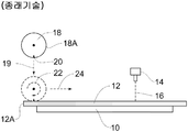
액정 디스플레이 등과 같은 컬러 디스플레이는 전형적으로 픽셀에 컬러를 제공하도록 사용되는 컬러 필터를 포함한다. 컬러 필터를 제조하는 하나의 기법은 레이저-유도 열 전사 프로세스를 포함한다. 종래의 특정 열 전사 프로세스가 도 1a에 개략적으로 도시되어 있다. 기판(10)(흔히, "수용 요소(receiver element)"로 지칭됨) 위에 도너 요소(12)(흔히, "도너 시트"로 지칭됨)가 도포된다. 컬러 필터 제조의 경우, 기판(10)은 전형적으로 유리로 구성되고 대체로 평면의 형상을 갖는다. 도너 요소(12)는 전형적으로 기판(10)에 비해 비교적 얇고 비교적 가요적인 시트이다. 도너 요소(12)는 예를 들어 플라스틱으로 구성될 수 있다. 도너 요소(12)는 도너 물질(미도시)을 포함한다. 도너 물질은 컬러 필터를 제조하는데 사용되는 착색제, 안료 등을 포함할 수 있다.Color displays, such as liquid crystal displays, typically include color filters used to provide color to the pixels. One technique for manufacturing color filters includes a laser-induced thermal transfer process. Certain conventional thermal transfer processes are schematically illustrated in FIG. 1A. A donor element 12 (commonly referred to as a "donor sheet") is applied over the substrate 10 (commonly referred to as a "receiver element"). In the case of color filter manufacture, the
도너 요소(12)는 도너 요소(12)로부터 기판(10)으로 도너 물질을 선택적으로 전사하도록 이미지 형식으로 노출된다. 소정의 노출 방법은 방사 빔을 방출하도록 방사원을 제어하는 것을 포함한다. 예를 들어, 도 1a에 도시되어 있는 바와 같이, 하나 이상의 대응하는 레이저 빔(16)을 제공하기 위해 하나 이상의 제어가능한 레이저(14)가 이용된다. 현재 바람직한 기법에서, 레이저 빔(들)(16)은 도너 요소(12)의 이미징된 영역으로부터 기판(10)의 대응하는 영역으로 도너 물질의 전사를 유도한다. 제어가능한 레이저(들)(14)는 비교적 변조하기 쉽고, 비교적 저가이며 비교적 작은 크기를 갖는 다이오드 레이저(들)를 포함한다. 이러한 레이저(들)(14)는 도너 요소(12)를 직접 이미지 형식으로 노출시키도록 제어가능하다. 일부 실시예에서, 마스크(미도시)가 사용되어 도너 요소(12)를 이미지 형식으로 노출시킨다.The
도너 물질이 도너 요소(12)로부터 기판(10)으로 이미지 형식으로 전사된 경우, 기판(10)으로부터 이미징된 도너 요소(12)를 제거하는 것이 일반적으로 필요하다. 예를 들어, 컬러 필터를 제조하는 동안, 제 1 도너 요소(12)는 적색 염료를 기판(10)에 도포하는데 사용될 수 있고, 제 2 도너 요소(12)는 녹색 염료를 도포하는데 사용될 수 있으며 제 3 도너 요소(12)는 청색 염료를 도포하는데 사용될 수 있다. 사용된 이후, 후속 도너 요소(12)가 도포 및 사용되기 전에 주어진 이미징된 도너 요소(12)는 기판(10)으로부터 제거된다.
When the donor material is transferred in image form from the
종래의 다양한 기법에 있어서, 도너 요소(12)는 하나 이상의 흡입 피처(20)를 포함하는 롤러(18)를 사용하여 기판(10)으로부터 제거된다. 롤러(18)는 (화살표(19)로 도시된 바와 같이) 도너 요소(12)의 에지(12A) 부근으로 이동되고 흡입 피쳐(20)를 통해 흡입이 수행되어, 도너 요소(12)의 에지(12A)는 흡입 피처(20)에 고정된다. 그런 다음, 롤러(18)는 (화살표(22)로 도시되어 있는 바와 같이) 회전되고 (화살표(24)로 표시된 바와 같이) 이동되어 기판(10)으로부터 도너 요소(12)를 롤러(18)의 원주면(18A) 상으로 휘감으며, 그에 따라 도너 요소(12)를 기판(10)으로부터 필링하게 된다.In various conventional techniques, the
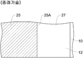
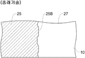
일부 경우, 제거 프로세스 동안, 도너 요소(12)의 노출된 영역에 대응하는 일부 도너 물질은 의도된 대로 기판(10)에 고정되기 보다는 도너 요소(12)에 부분적으로 고정된 채 유지될 수 있다. 도너 물질이 도너 요소(12)에 부분적으로 고정되게 되면 도너 요소(12)를 기판(10)으로부터 제거하는 것이 어려울 수 있다. 일부 경우, 기판(10)으로부터 도너 요소(12)의 제거는 기판(10)으로 전사된 일부 도너 물질과 도너 요소(12)에 부착된 채로 유지된 일부 도너 물질 사이에 불규칙적인 분리를 야기할 수 있다. 예를 들어, 도 1b는 기판(10)의 상단에 배치된 도너 요소(12)의 일부분을 나타낸다. 도너 요소(12)의 영역이 노출되어 이미징된 영역(25)을 형성한다. 이미징된 영역(25)은 이미징된 에지(25A)에 의해 이미징되지 않은 영역(27)으로부터 분리된다. 그러나, 기판(10)으로부터 도너 물질(12)을 제거하는 동안 이미징된 에지(25A)에서 명확히 분리하기 보다는, 이미징된 영역(25A)의 근처에서 이미징된 영역(25) 내의 보다 큰 구역 내에서 분리가 이루어질 수 있다. 도 1c에 도시되어 있는 바와 같이, 도너 요소(12)가 제거된 이후, 도너 물질은 이미징된 에지(25A)에 대응하는 기판(10)의 영역을 따라 고르게 분포된 채로 유지될 수 없다. 그 보다, 이 영역에 전사되어 유지된 도너 물질의 양은 원하는 것보다 적을 수 있고 이 영역을 따라 전사된 도너 요소의 분포는 불균일할 수 있다. 이것은 분열 및 그 밖의 다른 다양한 불연속을 포함하는 에지(25B)의 변형을 야기할 수 있다. 이들 분열된 에지는 최종 이미지에 못마땅한 가시적 아티팩트를 야기할 수 있다. 또한, 도너 물질은 이미징되지 않은 영역(27) 내로 연장될 수 있는데 이 또한 바람직하지 않다. In some cases, during the removal process, some donor material corresponding to the exposed area of
기판으로부터 이미징된 매체를 보다 효율적으로 제거하는 방법 및 장치를 제공하는 것이 일반적으로 바람직하다.It is generally desirable to provide a method and apparatus for more efficiently removing imaged media from a substrate.
도너 물질이 도너 요소로부터 기판으로 전사된 이후 도너 요소를 기판으로부터 보다 효율적으로 제거하는 방법 및 장치를 제공하는 것이 일반적으로 바람직하다.
It is generally desirable to provide a method and apparatus for more efficiently removing a donor element from a substrate after the donor material has been transferred from the donor element to the substrate.
본 발명은 매체를 이미징하는 방법에 관한 것이다. 매체는 기판 및 매체를 층형 구성으로 지탱하는 지지대(support) 상에 배치된다. 이미징 헤드는 이미징 헤드와 지지대 사이에서 상대적 이동이 이루어지는 동안 방사 빔을 이미징되는 매체의 표면 상으로 유도함으로써 매체를 이미징하도록 동작한다. 아이들러 롤러(idler roller)와 같은 롤러는 이미징된 매체와 접촉한다. 이 롤러는 이미징된 매체의 표면의 이미징되지 않은 영역과 접촉할 수 있는데, 이 이미징되지 않은 영역은 방사 빔이 가해지지 않은 이미징된 매체의 표면의 영역에 대응한다. 이미징되지 않은 영역은 매체의 에지 부분일 수 있다.The present invention relates to a method of imaging a medium. The medium is disposed on a support that holds the substrate and the medium in a layered configuration. The imaging head is operative to image the medium by directing the radiation beam onto the surface of the medium being imaged while relative movement is made between the imaging head and the support. A roller, such as an idler roller, contacts the imaged media. This roller may contact an unimaged area of the surface of the imaged medium, which corresponds to the area of the surface of the imaged medium to which no radiation beam is applied. The non-imaged area may be an edge portion of the medium.
롤러는 회전축을 중심으로 회전가능하다. 롤러의 회전축과 지지대 사이에 상대적 움직임이 발생함에 따라 롤러는 방사 빔이 가해진 이미징된 매체의 표면의 영역 상에서 롤링 방향을 따라 롤링된다. 롤러는 에지 부분으로부터 멀어지는 방향을 따라 이미징된 매체의 표면 상에서 롤링될 수 있다. 이미징된 매체는 그런 다음 기판으로부터 제거된다. 일 실시예에서, 이미징된 매체는 롤러의 원통형 표면의 일부분 위에 이징된 매체의 일부분을 감싸고 그와 동시에 이미징된 매체를 기판으로부터 필링함으로써 제거될 수 있다. 필링 방향은 롤링 방향과 동일한 방향일 수도 있고 반대 방향일 수 도 있다. 일 실시예에서, 롤링 방향은 스캔 방향, 지지대의 전달 방향 또는 기판 상에 형성된 줄무늬 특징의 방향과 평행할 수 있지만, 반드시 그럴 필요는 없다.The roller is rotatable about an axis of rotation. As relative movement occurs between the axis of rotation of the roller and the support, the roller is rolled along the rolling direction on the area of the surface of the imaged medium to which the radiation beam is applied. The roller may be rolled on the surface of the imaged medium along the direction away from the edge portion. The imaged medium is then removed from the substrate. In one embodiment, the imaged media can be removed by wrapping a portion of the aged media over a portion of the cylindrical surface of the roller and at the same time filling the imaged media from the substrate. The peeling direction may be the same direction as the rolling direction or may be the opposite direction. In one embodiment, the rolling direction may be parallel to the scan direction, the direction of delivery of the support or the direction of the stripe feature formed on the substrate, but need not be so.
이미징된 매체가 기판으로부터 제거된 이후, 추가의 매체가 지지대 상의 기판 상에 층형 구성으로 배치될 수 있다. 추가의 매체는 이미징 헤드와 지지대 사이에 상대적 이동이 이루어지는 동안 이미징될 수 있다. 이미징된 추가의 매체는 롤러의 회전축과 지지대 사이에서 상대적 이동 발생하는 동안 기판으로부터 제거될 수 있다.After the imaged media has been removed from the substrate, additional media can be placed in a layered configuration on the substrate on the support. Additional media may be imaged while relative movement is made between the imaging head and the support. The further media imaged may be removed from the substrate during the relative movement between the rotational axis of the roller and the support.
일 실시예에서, 테이크 업 롤러(take up roller)는 매체의 표면 상에 테이크 업 롤러를 롤링하지 않으면서 이미징된 매체의 일부분을 스풀링(spool)하는데 사용될 수 있다. 이미징된 매체의 일부분은 기판으로부터 이미징된 매체를 제거하면서 테이크 업 롤러 상에 스풀링될 수 있다. In one embodiment, a take up roller can be used to spool a portion of the imaged media without rolling the take up roller onto the surface of the media. A portion of the imaged media may be spooled onto the take up roller while removing the imaged media from the substrate.
일 실시예에서, 자기 입자 브레이크 또는 다른 적절한 브레이크와 같은 브레이크가 사용되어 이미징된 매체의 표면의 일부분 상에 롤러를 롤링하면서 롤러에 제동(drag)을 선택적으로 적용한다. In one embodiment, a brake, such as a magnetic particle brake or other suitable brake, is used to selectively apply a drag to the roller while rolling the roller on a portion of the surface of the imaged medium.
또 다른 실시예에서, 매체를 이미징하는 방법은 층형 구성의 기판 및 매체를 지탱하는 지지대를 제공하는 단계를 포함한다. 이미징 헤드는 매체 및 기판이 층형 구성으로 있는 동안 방사 빔을 매체 쪽으로 방출하여 매체를 이미징한다. 롤러는 이미징된 매체의 표면과 접촉한다. 이미징된 매체의 표면 상에 롤러를 롤링하는 동안 예를 들어, 회전식 제동과 같은 제동이 롤러에 선택적으로 적용된다. 이 제동은 브레이크에 의해 적용될 수 있거나 또는 액추에이터를 가동시킴으로써 적용될 수 있다. 이미징된 매체는 기판으로부터 제거된다. 롤러는 이미징된 매체가 기판으로부터 필링되기 전에 또는 그와 동시에 이미징된 매체의 표면 상에 롤링될 수 있다.In another embodiment, a method of imaging a medium includes providing a substrate in a layered configuration and a support for supporting the medium. The imaging head emits a radiation beam toward the medium while the medium and the substrate are in a layered configuration to image the medium. The roller contacts the surface of the imaged medium. Braking, for example rotary braking, is selectively applied to the rollers while rolling the rollers on the surface of the imaged media. This braking can be applied by a brake or by actuating the actuator. The imaged medium is removed from the substrate. The roller may be rolled on the surface of the imaged media before or at the same time as the imaged media is peeled from the substrate.
일 실시예에서, 롤러는 이미징된 매체의 표면 상에서 다수의 상이한 방향을 따라 롤링될 수 있고 롤러가 각 방향을 따라 표면 상에 롤링되는 경우 제동은 상이한 정도로, 상이한 시간에서 선택적으로 적용될 수 있다. 롤러는 이미징된 매체와 기판을 층형 구성으로 유지하면서 이미징된 매체의 표면 상에서 롤링될 수 있다. 롤러는 매체를 기판으로부터 필링하면서 이미징된 매체의 표면 상에서 롤링될 수 있다. 접촉 롤러는 표면 상에서 이미징된 매체를 롤링할 수 있고 이미징된 매체의 일부분은 기판으로부터 이미징된 매체를 필링하면서 접촉 롤러의 표면의 일부분 위에 래핑(wrapping)될 수 있다. 이미징된 매체의 표면 상에 테이크 업 롤러를 롤링하지 않으면서 이 테이크 업 롤러를 사용하여 이미징된 매체의 표면을 스풀링할 수 있다. 이미징된 매체의 부분이 테이크 업 롤러 상에 스풀링되면서 기판으로부터 이미징된 매체가 필링될 수 있다.In one embodiment, the rollers can be rolled along a number of different directions on the surface of the imaged media and braking can be selectively applied at different times and at different degrees when the rollers are rolled on the surface along each direction. The roller may be rolled on the surface of the imaged media while maintaining the imaged media and substrate in a layered configuration. The roller may be rolled on the surface of the imaged media while filling the media from the substrate. The contact roller can roll the imaged media on the surface and a portion of the imaged media can be wrapped over a portion of the surface of the contact roller while filling the imaged media from the substrate. This take up roller can be used to spool the surface of the imaged media without rolling the take up roller onto the surface of the imaged media. The imaged media can be filled from the substrate while the portion of the imaged media is spooled onto the take up roller.
또 다른 실시예에서, 기판은 지지대 상에서 지탱된다. 도너 요소는 기판을 지지대 상에 지탱한 이후 기판 상에 배치된다. 이미징 헤드는 방사 빔을 도너 요소로 지향시킴으로써 도너 요소를 이미징하도록 동작한다. 회전축을 중심으로 회전가능한 롤러는 이미징된 도너 요소의 표면과 접촉한다. 롤러의 회전축과 이미징된 도너 요소 사이에 다수의 상대적 이동이 발생되어 롤러는 이미징된 도너 요소의 하나 이상의 이미징된 영역을 여러번 롤링한다. 롤러는 하나 이상의 이미징된 영역 상에서 롤링될 때마다 동일한 방향 또는 다른 방향으로 롤링될 수 있다.In another embodiment, the substrate is supported on the support. The donor element is placed on the substrate after supporting the substrate on the support. The imaging head is operative to image the donor element by directing the radiation beam onto the donor element. The rotatable roller about the axis of rotation contacts the surface of the imaged donor element. A number of relative movements occur between the axis of rotation of the roller and the imaged donor element such that the roller rolls one or more imaged regions of the imaged donor element several times. The rollers may be rolled in the same direction or in different directions each time they are rolled on one or more imaged areas.
롤러의 회전축과 이미징된 도너 요소 사이의 또 다른 상대적 이동 동안보다는 롤러의 회전축과 이미징된 도너 요소 사이에서 한번의 상대적 이동 동안에 롤러가 이미징된 도너 요소의 하나 이상의 영역 상에 롤링함에 따라 브레이크 또는 다른 장치를 통해 상이한 양의 제동이 롤러에 가해질 수 있다.Brake or other device as the roller rolls on one or more regions of the imaged donor element during one relative movement between the axis of rotation of the roller and the imaged donor element rather than during another relative movement between the axis of rotation of the roller and the imaged donor element Different amounts of braking can be applied to the rollers through.
이미징된 도너 요소는 롤러의 회전축과 이미징된 도너 요소 사이의 상대적 이동 동안 기판으로부터 제거된다. 이미징된 도너 요소가 기판으로부터 제거된 이후 기판은 지지대로부터 제거된다. 기판은 롤러의 회전축과 이미징된 도너 요소 사이의 다수의 상대적 이동 중 임의의 상대적 이동 동안에는 지지대로부터 제거되지 않는다.The imaged donor element is removed from the substrate during the relative movement between the axis of rotation of the roller and the imaged donor element. The substrate is removed from the support after the imaged donor element is removed from the substrate. The substrate is not removed from the support during any of the plurality of relative movements between the axis of rotation of the roller and the imaged donor element.
이미징된 도너 요소가 기판으로부터 제거된 이후, 제 2 도너 요소가 기판 상에 배치될 수 있고 이미징될 수 있다. 제 2 도너 요소는 롤러의 회전축과 이미징된 제 2 도너 요소 사이의 상대적 이동이 발생하는 동안 기판으로부터 제거될 수 있다.After the imaged donor element is removed from the substrate, a second donor element can be placed on the substrate and imaged. The second donor element can be removed from the substrate while the relative movement between the axis of rotation of the roller and the imaged second donor element occurs.
이미징된 도너 요소의 영역 상에 롤러를 롤링하게 되면 도너 요소가 기판으로부터 필링될 때 피쳐의 에지를 따라 발생하는 에지 불연속을 감소시킬 수 있다. 롤러가 이미징된 도너 요소의 영역 상에서 롤링될 때 롤러에 가해지는 제동의 정도를 증가시키도록 구성된 브레이크를 사용함으로써, 이미징된 도너 요소가 기판으로부터 필링될 때 기판의 표면으로 전사되어 유지되는 도너 물질의 양은 조절된다.Rolling the roller on the area of the imaged donor element can reduce edge discontinuities that occur along the edge of the feature when the donor element is peeled from the substrate. By using a brake configured to increase the amount of braking applied to the rollers when the rollers are rolled on the area of the imaged donor element, the donor material is transferred to and maintained on the surface of the substrate when the imaged donor element is peeled from the substrate. The amount is adjusted.
또 다른 실시예에서, 매체를 이미징하는 장치가 제공되는데, 이 장치는 기판 및 매체를 층형 구성으로 지탱하도록 구성된 지지대를 포함한다. 이미징 헤드는 방사 빔을 매체로 방출하여 매체를 이미징하도록 구성된다. 롤러가 제공되고 브레이크는 이 롤러에 제동을 선택적으로 적용한다. 섀시(chassis)는 롤러가 섀시에 대해 회전가능하도록 롤러를 지탱한다. 하나 이상의 제어기를 포함할 수 있는 롤러는 방사 빔을 매체 쪽으로 방출하도록 이미징 헤드를 동작시킨다. 롤러는 섀시와 지지대 사이에 상대적 이동을 야기하여 롤러를 이미징된 매체의 부근으로 이동시키되 이미징된 매체와 기판은 층형 구성으로 유지된다. 제어기는 섀시와 지지대 사이에 다수의 상대적 이동을 야기하여 롤러가 이미징된 매체의 표면 상에 여러번 롤링하도록 한다. 또한, 롤러는 섀시와 지지대 사이의 하나의 상대적 이동과 섀시와 지지대 사이의 또 다른 상대적 이동 사이에서 롤러에 인가되는 제동을 선택적으로 변경하도록 브레이크를 제어할 수 있다.
In another embodiment, an apparatus for imaging media is provided, the apparatus including a substrate and a support configured to support the media in a layered configuration. The imaging head is configured to emit a radiation beam into the medium to image the medium. A roller is provided and the brake selectively applies braking to this roller. The chassis supports the rollers such that the rollers are rotatable relative to the chassis. A roller, which may include one or more controllers, operates the imaging head to emit a radiation beam towards the media. The rollers cause relative movement between the chassis and the support to move the rollers in the vicinity of the imaged media while the imaged media and substrate are maintained in a layered configuration. The controller causes a number of relative movements between the chassis and the support causing the roller to roll multiple times on the surface of the imaged media. The roller may also control the brake to selectively change the braking applied to the roller between one relative movement between the chassis and the support and another relative movement between the chassis and the support.
도 1a는 이미징된 도너 요소를 기판으로부터 필링하는 종래의 열 전사 프로세스를 나타내는 도면,
도 1b 및 도 1c는 이미징된 도너 요소가 통상적으로 기판으로부터 필링될 때 발생하는 에지 불연속의 형태를 나타내는 도면,
도 2a는 본 발명의 일 실시예에 따른 이미지 형성 시스템의 평면도를 개략적으로 나타내는 도면,
도 2b는 도 2a의 이미징 시스템의 부분적인 단면도를 개략적으로 나타내는 도면,
도 2c는 본 발명의 일 실시예에 따라 기판으로부터 이미징된 도너 요소를 제거하기 전에 접촉 롤러를 이미징된 도너 요소 상에 롤링하는 것을 개략적으로 나타내는 도면,
도 2d, 2e 및 2f는 본 발명의 예시적인 실시예에 따라 도 2c의 도너 요소를 제거하기 위해 시트 제거 장치에 의해 이용되는 일련의 동작을 개략적으로 나타내는 도면,
도 3은 본 발명의 예시적인 실시예에 따른 방법을 나타내는 흐름도,
도 4는 기판에 의해 지탱되는 이미징된 도너 요소 상에서 접촉 롤러가 롤링함에 따른 접촉 롤러의 움직임을 나타내는 개략적인 힘 도면, 1A illustrates a conventional thermal transfer process for filling an imaged donor element from a substrate,
1B and 1C show the shape of edge discontinuities that occur when an imaged donor element is typically peeled from a substrate,
2a schematically illustrates a plan view of an image forming system according to an embodiment of the present invention;
FIG. 2B schematically illustrates a partial cross-sectional view of the imaging system of FIG. 2A;
2C schematically illustrates rolling a contact roller onto an imaged donor element prior to removing the imaged donor element from the substrate in accordance with one embodiment of the present invention;
2D, 2E and 2F schematically illustrate a series of operations used by the sheet removal apparatus to remove the donor element of FIG. 2C in accordance with an exemplary embodiment of the present invention;
3 is a flowchart illustrating a method according to an exemplary embodiment of the present invention;
4 is a schematic force diagram illustrating the movement of a contact roller as the contact roller rolls on an imaged donor element carried by a substrate;
후속하는 상세한 설명을 통해, 보다 철저한 이해를 당업자에게 제공하기 위해 세부사항이 제공된다. 그러나, 잘 알려져 있는 요소는 본 개시물을 불필요하게 불명료하게 하는 것을 피하기 위해 도시되거나 또는 설명되지 않았다. 따라서, 상세한 설명 및 도면은 제한적인 의미라기보다는 예시적인 의미로서 간주되어야 한다. 또한, 도면은 실제 축척대로 도시될 필요는 없으며 그들 중 일부는 명료성을 위해 과장될 수 있다.In the following detailed description, details are provided to provide a more thorough understanding to those skilled in the art. However, well known elements have not been shown or described in order to avoid unnecessarily obscuring the present disclosure. The specification and drawings are, accordingly, to be regarded in an illustrative rather than a restrictive sense. In addition, the drawings need not be drawn to scale, some of which may be exaggerated for clarity.
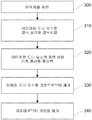
도 3은 본 발명의 예시적인 실시예에 따라 기판 상에 지탱되는 이미징된 매체를 제거하는 방법을 나타내는 흐름도이다. 도 3에 도시되어 있는 다양한 단계는 장치(100)를 참조하여 설명되며, 그 중 일부는 본 발명의 예시적인 실시예에 따른 도 2a 내지 도 2f에 도시되어 있다. 이것은 오직 예시 목적일 뿐이며 다른 적절한 이미지 형성 장치가 본 발명에 사용될 수 있다. 단계(300)에서, 매체는 이미지를 형성하도록 처리된다. 이 예시적인 실시예에서, 이미지는 이미징 기법(즉, 노출 기법으로도 알려져 있음)에 의해 형성된다. 이미징 기법은 방사 빔(예를 들어, 레이저 빔)을 사용하여 표면 상에 이미지를 형성한다. 이들 이미지는 다양한 방식으로 형성될 수 있다. 예를 들어, 이미징 기법은 이미지 수정가능 층의 특질 또는 특성을 변경하여 그 상에 이미지를 형성할 수 있다. 이미징 기법은 표면을 제거하여 그 상에 이미지를 형성하는데 사용될 수 있다. 이미징 기법은 도너 물질을 표면으로의 전사를 용이하게 하여 그 상에 이미지를 형성하는데 사용될 수 있다.3 is a flow chart illustrating a method of removing an imaged medium supported on a substrate in accordance with an exemplary embodiment of the present invention. The various steps shown in FIG. 3 are described with reference to
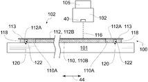
이 예시적인 실시예에서, 예를 들어, 열 전사 프로세스가 이용되고 매체는 도너 요소(112)를 포함한다. 레이저와 같은 방사원(미도시)을 포함하는 이미징 헤드(102)가 제공되어 도너 물질(또한 미도시됨)을 도너 요소(112)로부터 기판(110)의 표면으로 전사한다(도 2a에서 점선으로 도시됨). 이미징 헤드(102)는 하나 이상의 채널(114)을 포함할 수 있다. 이 예시적인 실시예에서, 이미징 헤드(102)는 채널(114)의 배열을 포함하는데, 각 채널(114)은 개별적으로 제어가능하여 방사빔(116)(도 2a에서는 미도시)을 방출한다. 이미징 헤드(102)는 방사 빔(116)이 도너 요소(112)의 다양한 영역 상에 가해지도록 방사 빔(116)을 유도하도록 동작한다. 이미징 전자장치(103)는 제어기(108)에 의해 제공된 이미지 데이터(104)에 따라 채널(102)로부터 방사 빔(116)의 방사를 제어한다.In this exemplary embodiment, for example, a thermal transfer process is used and the medium includes
이 예시적인 실시예에서, 기판(110), 이미징 헤드(102) 또는 이들의 조합은 서로 상대적으로 이동하며 그와 동시에 채널(114)은 이미지 데이터(104)에 응답하여 제어되어 방사 빔(116)을 이미지 형식으로 도너 요소(112) 위에 스캐닝한다. 일부 경우, 이미징 헤드(102)는 정적이며 기판(110)이 이동한다. 다른 경우, 기판(110)이 정적이고 이미징 헤드(102)가 이동한다. 다른 경우, 이미징 헤드(102) 및 기판(110)이 이동한다. 본 발명의 일부 예시적인 실시예에서, 이미징 헤드(102)는 도너(112)를 단계적이고 반복적인 방식으로 노출시킨다. 이들 실시예에서, 이미징 헤드(102)와 도너 요소(112) 간의 상대적 이동은 노출 샷(shots) 사이에 발생할 수 있다. 다른 경우, 도너 요소(112)는 단일 노출 또는 스캔 내에서 이미징되기에는 너무 클 수 있다. 이미지를 완성하기 위해 이미징 헤드(102)의 다수의 노출 또는 스캔이 필요할 수 있다.In this exemplary embodiment, the
이미징 헤드(102)를 기판(10)에 대해 이동시키기 위해 임의의 적절한 메카니즘이 적용될 수 있다. 평상형 마킹 시스템이 전형적으로 사용되어 실질적으로 평탄한 배향을 포함하는 표면 상에 이미지를 형성한다. Gelbart에 의한 미국 특허 제 6,957,773호는 디스플레이 패널 노출에 적합한 고속 평상형 이미저(imager)를 기술한다. 일부 예시적인 실시예에서, 디스플레이 어셈블리 상의 이미지 형성에 영향을 주도록 "드럼형" 지지대의 외부 또는 내부 표면에 적절히 가요적인 기판이 고정될 수 있다.Any suitable mechanism can be applied to move the
도 2a는 장치(100)의 이미지 형성 시스템의 개략적인 평면도를 나타낸다. 도 2a에서, 지지대(101)는 기판(110) 및 도너 요소(112)를 층형 구성으로 지탱하도록 제공된다. 이 예시적인 실시예에서, 지지대(101)는 기판(110) 및 도너 요소(112)를 주 스캔축(42)과 정렬된 경로를 따라 운송하도록 구성된다. 이 실시예에서, 지지대(101)는 다수의 운송 방향(즉, 전방향(42A) 및 역방향(42B))을 따라 이동가능하다. 전방향(42A)은 역방향(42B)과 반대방향이다. 지지대(101)는 전방향(42A)과 역방향(42B) 사이에서 왕복 운동한다. 이미징 헤드(102)는 지지대(101)를 버티고 있는 지지대(105) 상에 이동가능하게 지탱된다. 이 예시적인 실시예에서, 이미징 헤드(102)는 서브 스캔축(44)과 정렬된 경로를 따라 이동가능하다. 이 실시예에서, 이미징 헤드(102)는 방향(44A)을 따라 멀어지도록 또한 방향(44B)을 따라 가까워지도록 이동가능하다. 멀어지는 방향(44A)은 가까워지는 방향(44B)과 반대방향이다. 이 예시적인 실시예에서, 이미징 헤드(102)는 도너 요소(102) 위에 방사 빔(116)을 양방향으로 스캐닝하여 이미지를 형성할 수 있다. 양방향 스캐닝 기법은 이미징 생산성을 강화할 수 있는데 그 이유는 반대되는 스캔 방향 각각에서 스캔이 이루어지기 때문이다.2A shows a schematic top view of an image forming system of
움직임 시스템(109)이 제공되어 지지대(101) 및/또는 이미징 헤드(102)의 움직임을 야기하고 적절한 드라이브, 전송 부재(member) 및/도는 안내 부재를 포함할 수 있다. 움직임 시스템(109)은 하나 이상의 움직임 시스템을 포함할 수 있다. 당업자라면 별도의 움직임 시스템이 사용되어 장치(100) 내의 상이한 시스템을 동작시킬 수 있음을 알 것이다.
하나 이상의 제어기를 포함할 수 있는 제어기(108)는 움직임 시스템(109)을 포함하나 여기에 국한되지 않은 장치(100)의 하나 이상의 시스템을 제어하는데 사용된다. 제어기(108)는 이미지 데이터(104)가 이미징 헤드(102)로 전사되도록 하고 이 데이터에 따라 방사 빔(116)을 방출하도록 이미징 헤드를 제어할 수 있다. 제어기(108)는 장치(100) 이외의 시스템을 제어할 수 있다. 제어기(108)는 적절한 소프트웨어를 실행하고 적절한 하드웨어와 함께 하나 이상의 데이터 프로세서를 포함하도록 구성될 수 있는데, 상기 적절한 하드웨어는 비-제한적인 예로서 액세스가능 메모리, 로직 회로, 드라이버, 증폭기, A/D 및 D/A 변환기, 입/출력 포트 등을 포함할 수 있다. 제어기(108)는 마이크로프로세서, 컴퓨터 온 칩, 컴퓨터의 CPU 또는 임의의 다른 적절한 마이크로제어기 등을 포함할 수 있으며, 여기에 국한되지 않는다. 제어기(108)는 시스템을 취급하는 물질과 연관될 수 있다.
도 2b는 장치(100)의 이미지 형성 시스템의 개략적인 부분 단면도를 나타낸다. 예시되어 있는 열 전사 프로세스에서, 기판(110)은 당업계에 잘 알려져 있는 다양한 기법(예를 들어, 흡입)을 통해 지지대(101)에 고정될 수 있다. 이 예시되어 있는 실시예에서, 도너 요소(112)는 기판(110)과 층형 구성으로 배치되는데 도너 요소(112)는 기판(110)이 지지대(101) 위에 지탱된 이후 기판(110) 위에 놓인다. 이미지 품질을 보존하기 위해, 이미징 동안 도너 요소(112)가 기판(110)에 대해 이동하지 않도록 하는 것이 바람직하다. 도 2b에 도시되어 있는 바와 같이, 지지대(101)는 기판(110)의 에지로부터 횡으로 이격되고 기판(110)의 두께와 실질적으로 유사한 높이를 갖는 스탠드(stands)(118)를 포함한다. 지지대(101)는 또한 스탠드(118)와 기판(110) 사이의 공간(122)에 흡입을 적용하는 하나의 이상의 흡입 피쳐(120)를 포함한다. 이 흡입은 도너 요소(112)를 기판(110)에 고정시킨다. 당업자라면, 도너 요소(112)를 기판(110)에 고정시키는 다른 추가의 및/또는 또 다른 기법이 존재하며 본 발명은 이러한 추가의 및/또는 또 다른 도너 요소 고정 기법을 포함하는 것으로 이해되어야 함을 알 것이다.2B shows a schematic partial cross-sectional view of an image forming system of
도너 요소(112)로부터 기판(110)으로의 도너 물질의 전달은 예를 들어 다양한 레이저 유도 열 전사 기법을 사용하여 구현될 수 있다. 본 발명에서 사용되는 레이저 유도 열 전사 프로세스의 예는 레이저 유도 "염료 전사" 프로세스, 레이저 유도 "용융 전사" 프로세스, 레이저 유도 "제거 전사" 프로세스 및 레이저 유도 "대량 전사" 프로세스를 포함한다.Transfer of donor material from
일반적으로, 기판(110), 도너 요소(112) 및 도너 물질의 구성은 특정 이미징 애플리케이션에 의존한다. 특정 실시예에서, 이미징 장치(100)는 기판(110) 상의 디스플레이를 위한 컬러 필터를 제조하는데 사용된다. 이러한 실시예에서, 기판(110)은 전형적으로 투명 물질(예를 들어, 유리)로 구성되고, 도너 요소(112)는 전형적으로 플라스틱으로 구성되며 도너 물질은 전형적으로 하나 이상의 착색제를 포함한다. 이러한 착색제는 예를 들어 적절한 염료 기반 또는 안료 기반 조성물을 포함할 수 있다. 도너 물질은 또한 하나 이상의 적절한 접합 물질을 포함할 수도 있다.In general, the configuration of
예시되어 있는 실시예에서, 이미징 헤드(102)는 도너 요소(112)의 이미징된 영역(112B)의 다양한 영역에 방사 빔(116)이 가해지도록 방사 빔(116)을 방출하게 끔 강제된다. 따라서, 도너 요소(112)의 영역(112A)은 이미징되지 않은 영역으로서 남겨지고 일부 경우 이미징된 영역(112B) 주위에 경계를 제공한다. 따라서, 예시되어 있는 실시예에서, 도너 물질은 도너 요소(112)로부터 기판(110)의 이미징된 영역(110B) 상으로만 전달되고 기판(110)의 이미징되지 않은 영역(110A) 상으로는 전달되지 않는다. 예시되어 있는 실시예에서, 이미징되지 않은 영역(112A)의 부분(113)은 기판(110) 위에 걸쳐있고 스탠드(118)에 의해 지탱된다. In the illustrated embodiment, the
이미징 프로세스의 끝에서, 도너 요소(112)는 기판(110)으로부터 제거된다. 이 예시적인 실시예에서, 도너 요소(112)는 기판(110) 상에 형성된 다양한 피처의 에지에서 분열 및 다른 불연속의 존재를 감소시키는 방식으로 기판(110)으로부터 제거되는 것이 바람직하다. At the end of the imaging process,
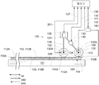
도 2c는 지지대(110), 기판(110) 및 이미징된 도너 요소(112)의 일 종단을 나타내는 개략적인 부분적인 측면도를 나타낸다. 이미징된 도너 요소(112)를 기판(110)으로부터 제거하는 것은 이 예에서 장치(100)의 일부분을 형성하는 시트 제거 장치(129)에 의해 수행된다. 예시되어 있는 실시예에서, 시트 제거 장치(129)는 섀시(136) 및 대응하는 한 쌍의 롤러 커플링(접촉 롤러 커플링(138) 및 테이크업 롤러 커플링(140)) 에 의해 섀시(136)에 기계적으로 결합되는 다수의 롤러(즉, 접촉 롤러(130) 및 테이크업 롤러(132))를 포함한다.2C shows a schematic partial side view showing one end of the
롤러(130,132)는 바람직하게 실질적으로 원통의 형상을 갖는다. 접촉 롤러 커플링(138) 및 테이크업 롤러 커플링(140)은 그들의 제각기의 롤러(130,132)가 그들의 대응하는 회전축(130A,132A)을 중심으로 회전하도록 한다. 예시되어 있는 실시예에서, 테이크업 롤러 커플링(140)은 섀시(136)에 대한 테이크-업 롤러(132)의 축(132A)의 이동을 야기하는 액추에이터(133)를 포함한다. 액추에이터(133)는 본 명세서에서 "테이크-업 롤러 축-위치 액추에이터(133)"로서 지칭된다. 테이크-업 롤러 축-위치 액추에이터(133)는 신호(135)를 사용하여 제어기(108)에 의해 제어될 수 있다. 테이크-업 롤러 축-위치 액추에이터(133)는 일반적으로 임의의 적절하게 결합된 액추에이터를 포함할 수 있다. 테이크-업 롤러 축- 위치 액추에이터(133)를 제공하는데 사용될 수 있는 액추에이터의 비-제한적인 예는 전자 모터 및/또는 공기 액추에이터를 포함한다.The
예시되어 있는 실시예에서, 테이크-업 롤러 커플링(140)은 또한 테이크-업 롤러(132)의 회전을 그의 회전축을 중심으로 야기하는 테이크-업 롤러 회전 액추에이터(139)를 포함한다. 테이크-업 롤러 회전 액추에이터(139)는 신호(141)를 사용하여 제어기(108)에 의해 제어될 수 있다. 바람직하게, 테이크-업 롤러 회전 액추에이터(139)는 일반적으로 임의의 적절하게 구성된 액추에이터를 포함할 수 있다.In the illustrated embodiment, the take-up
도시되어 있는 실시예에서, 테이크-업 롤러(132)는 또한 하나 이상의 흡입 피처(134)를 포함한다. 흡입 피처(134)는 흡입원(143)과 유체 통신하도록 결합된 오리피스(orifices)를 포함할 수 있다. 당업계에 알려져 있는 바와 같이, 흡입원(143)은 적절하게 구성된 펌프 등과 같이 양 또는 음의 압력 차이를 발생시키는 메카니즘을 포함할 수 있다. 흡입원(143)은 흡입원(143)에 의한 흡입 인가와 관련된 하나 이상의 밸브 또는 유사한 구성요소(미도시)를 포함할 수 있는 신호(145)를 사용하여 제어기(108)에 의해 제어될 수 있다.In the embodiment shown, take-up
예시되어 있는 실시예에서, 접촉 롤러(130)는 비-구동 "아이들러"(non-driven "idler") 제어기이다. 시트 제거 장치(129)는 또한 지지대(101)와 섀시(136) 간의 상대적 이동을 야기하는 하나 이상의 섀시-위치 액추에이터(131)를 포함할 수 있다. 지지대(101)와 섀시(136) 간의 상대적 이동은 지지대(101)와 롤러(130,132) 간의 대응하는 이동을 야기한다. 예시되어 있는 실시예에서, 섀시-위치 액추에이터(131)는 지지대(101)에 대한 섀시(136)의 이동을 야기하여 지지대(101)와 섀시(136) 간의 상대적 이동을 발생시킨다. 또 다른 실시예에서, 섀시-위치 액추에이터(131)는 섀시(136)에 대해 지지대(101)의 이동을 야기하여 지지대(101)와 섀시(136) 간의 상대적 이동을 발생시킨다. 섀시-위치 액추에이터(131)는 일반적으로 임의의 하나 이상의 적절하게 결합된 액추에이터를 포함할 수 있다. 섀시-위치 액추에이터(131)를 제공하는데 사용될 수 있는 액추에이터의 비-제한적인 예는 적절하게 결합된 전자 모터 및/또는 공기 액추에이터를 포함한다.In the illustrated embodiment, the
기판(110)으로부터 이미징된 도너 요소(112)를 제거하는 것이 바람직한 경우, 제어기(108)는 섀시-위치 액추에이터(131)가 섀시(136)와 지지대(101) 간의 상대적 이동을 야기하도록 하는 신호를 사용함으로써, 섀시(136)와 시트 제거 장치(129)의 나머지는 도너 요소(112)의 하나의 에지 부분(115A) 부근에 배치된다(도 2c 참조). 예시되어 있는 실시예에서, 시트 제거 장치(129)는 수직 방향으로부터 도너 요소(112)에 접근한다. 또 다른 실시예에서, 섀시-위치 액추에이터(131)는 다른 방향으로부터 시트 제거 장치(129)가 도너 요소(112)에 접근하도록(또는 도너 요소(112)가 시트 제거 장치(129)로 접근하도록) 할 수 있다. 단계(310)에서, 시트 제거 장치(129)는 접촉 롤러(130)가 도너 요소(112)와 접촉할 때까지 도너 요소(112) 쪽으로 이동한다. 바람직하게, 접촉 롤러(130)는 이미징되지 않은 영역(112A)(즉, 이미징된 영역(112B) 밖)에서 도너 요소(112)와 접촉한다. 접촉 롤러(130)와 도너 시트(112) 간의 이러한 접촉 위치는 본 발명에 필수적이지는 않지만 도너 요소(112)의 이미징된 영역(112B)에서의 접촉 롤러(130)의 충돌을 피할 수 있고 이러한 충돌로부터 야기될 수 있는 기판(110)의 대응하는 이미징된 영역(110B)에서의 이미지의 임의의 대응하는 저하를 방지한다. 이 예시적인 실시예에서, 테이크-업 롤러(132)는 도너 요소(112)와 접촉하지 않았다. 이 예에서, 테이크-업 롤러 축-위치 액추에이터(133)는 테이크-업 롤러(132)가 도너 요소(112)와 접촉하지 않도록 제어된다.If it is desired to remove the imaged
단계(320)에서, 접촉 롤러(130)는 이미징된 도너 요소(112)의 일부분의 표면 상에서 롤링된다. 이 예시적인 실시예에서, 접촉 롤러(130)는 단계(300) 동안 방사 빔이 가해진 도너 요소(112)의 영역 상에서 롤링된다. 이 예시적인 실시예에서, 접촉 롤러(130)는 에지 부분(115A) 부근의 이미징되지 않은 영역(112A)으로부터 이미징된 영역(112B)을 지나 에지 부분(115B) 부근의 이미징되지 않은 영역(112A)까지 연장하는 경로를 따라 롤링된다. 제어기(108)는 롤링 방향(화살표 148A로 도시됨)을 따라 섀시-위치 액추에이터)(131)가 섀시(136)(롤러(130,132)를 포함)를 이동시키도록 하는 신호를 사용하여 접촉 롤러(130)가 지지된 도너 요소(112) 상에서 롤링하도록 한다. 이 예시적인 실시예에서, 접촉 롤러(130)는 이미징된 도너 요소(112) 상에서 롤링됨에 따라 (화살표(144)로 도시되어 있는 바와 같이) 회전한다. 도 2c에 도시되어 있는 바와 같이, 이것은 접촉 롤러(130)의 회전축(130A)이 화살표(148A)의 방향을 따라 이동하게 한다. 도 2c는 이미징된 도너 요소(112) 및 기판(110)이 그들의 층형 구성으로 여전히 배치되어 있는 동안 접촉 롤러(130)가 이미징된 도너 요소(112) 상에서 롤링되는 것을 도시한다. In
본 발명자는 놀랍게도 접촉 롤러(130)와 같은 롤러를 이미징된 도너 요소(112) 상에 롤링하게 되면 이미징된 도너 요소(112)가 후속하여 기판(110)으로부터 제거될 때 에지 불연속과 같은 아티팩트의 존재를 줄일 수 있다는 것을 단정하였다. 특히, 본 발명자는 이미징된 도너 요소(112)를 기판(110)으로부터 제거하기 전에 롤링하게 되면 특히 도너 요소(112)가 기판(110)으로부터 필링될 때 이미징된 피처의 에지에서의 도너 물질의 분열이 감소될 수 있다는 것을 알게 되었다. 비록 본 발명자는 임의의 특정 이론에 국한되는 것을 원하지는 않지만, 형성된 이미지의 가시적 특성이 개선되는 하나의 가능한 이유는 접촉 롤러(130)가 이미징된 도너 요소(112) 상에서 롤링됨에 따라 이미징된 도너 요소(112)와 기판(110) 사이에 "마이크로-편차"에 의한 것일 수 있다. 그러나, 추가의 또는 또 다른 원인에 의해 본 발명에 의해 제공되는 바와 같은 개선된 이미지 특성이 달성될 수도 있음을 이해해야한다.Surprisingly, when the inventors roll a roller, such as
도 4는 접촉 롤러(130)가 지지대 도너 요소(112) 상에 롤링됨에 따른 접촉 롤러(130)의 움직임을 나타내는 힘의 개략도를 나타낸다. 계면력(interface force)(F)을 제외하면, 모든 힘 및 모멘트는 접촉 롤러(130)에 작용하는 것으로 도시되어 있다. 접촉 롤러(130)에 작용하는 힘은 접촉 롤러(130)에 작용하는 부하(W)를 포함한다. 부하(W)는 섀시-위치 액추에이터(131)에 의해 접촉 롤러(130)에 작용하는 힘을 포함할 수 있다. 힘(P)은 지지된 도너 요소(112)의 표면 상에서 접촉 롤러를 화살표(148A)의 방향을 따라 이동시키는데 필요한 힘을 나타내고, 이 예시적인 실시예에서는 섀시-위치 액추에이터(131)에 의해 제공된다. 커플(M)은 접촉 롤러에 작용하고 화살표(144)의 회전 방향에 반대되는 부분 저항 또는 제동을 나타낸다. 이 제동은 접촉 롤러 커플링(138)의 베어링(미도시)의 부분적인 저항을 포함한 다양한 요인에 의해 발생할 수 있다. 접촉 롤러(130)는 롤러(130)와 지지된 도너 요소(112) 사이의 접촉 지점에서 다양한 변형을 야기할 수 있는 순응 표면(compliant surface)를 포함할 수 있다. 이러한 변형은 도 4의 영역(170)에 도시되어 있다. 이들 변형은 접촉 롤러(130)와 도너 요소(112) 간의 접촉이 단일 접촉 라인이 아니라 "롤링 저항"을 야기할 수 있는 소정의 영역에 걸쳐 발생하도록 할 수 있다. 도 4에 도시되어 있는 변형은 접촉 롤러(130)에 국한되어 있지만, 롤러가 롤링하는 표면 상에서도 변형이 발생할 수 있음을 이해해야 한다. 도 4는 접촉 롤러(130) 상에서 지지된 도너 요소(112)에 의해 이 영역에 걸쳐 인가된 힘의 결과는 지점(171)에서 인가된 반동력(R)이다. 지점(171)은 회전축(130A) 바로 밑에 위치하지 않고, 약간 그 앞에 위치한다. 지점(171)은 거리(b)만큼 회전 중심(172)으로부터 이탈된다. 거리(b)는 당업계에서는 롤링 저항의 계수로서 알려져 있다. 그러나, b는 길이의 단위로 표현되기 때문에 크기가 없는 계수가 아님을 유의해야 한다. 반동력(R)의 요소는 접촉 롤러(130)와 지지된 도너 요소(112) 간의 마찰력(f1)이다. 계면력(F)은 또한 도너 요소(112)와 기판(110) 사이에 존재한다. 접촉 롤러(130)의 반경은 "r"로서 도시되어 있다. 4 shows a schematic of the force representing the movement of the
지점(171) 주위에서 접촉 롤러(130)에 작용하는 모멘트의 합계는 후속하는 관계식(즉, 롤러는 일정한 속도로 움직이는 것으로 가정함)으로 표현될 수 있다.The sum of the moments acting on the
![]()
![]()
접촉 롤러(130)의 이동 방향(148A)을 따라 접촉 롤러(130)에 작용하는 힘의 합계는 후속하는 관계식(즉, 롤러는 일정한 속도로 움직이는 것으로 가정함)으로 표현될 수 있다.The sum of the forces acting on the
![]()
![]()
관계식(1) 및 (2)을 재결합시킴으로써, 후속하는 관계식이 수립될 수 있다.By recombining relations (1) and (2), the following relations can be established.
![]()
![]()
이들 파라미터들이 결합되어 마찰력(f1)이 계면력(F)을 초과하는 경우, 도너 요소(112)와 기판(110) 사이에 소정의 편차가 발생할 수 있다. 마이크로-편차로서 지칭되는 소량의 편차는 접촉 영역 부근의 도너 요소-기판 계면의 영역에서 발생할 수 있다. 계면력(F)은 다양한 요인에 의존할 수 있는데, 이 다양한 요인은 이미징된 도너 요소(112)와 기판(110) 간의 홀드다운 힘(hold down force)(예를 들어, 도너 요소(112)와 기판(10) 사이에 인가된 흡입), 부하(W) 및 도너 요소-기판 계면에 관련된 다양한 마찰 파라미터를 포함할 수 있다. 다른 요인은 형성된 다양한 이미지 피처의 경계에서 도너 물질을 절단(shear)하기 위해 압도적이어야 하는 절단력을 포함할 수 있다. 마찰력(f1)이 계면력(F)을 능가할 만큼 충분히 큰 경우, 이미징된 피처의 경계에서의 도너 물질은 절단될 수 있는데, 그 이유는 마찰력(f1)이 이미징된 피처 경계 부근에서 이미징된 도너 요소(112)의 국부적인 절단을 야기하기 때문이다. 도너 물질의 국부적인 절단은 이미징된 도너 요소(112)가 기판(110)으로부터 필링되는 경우 이미징된 피처 경계에서 발생할 수 있는 분열 양을 감소시킬 수 있다. 본 발명자는 이미징된 영역(112A)을 가로질러 접촉 롤러(130)를 롤링하게 되면 이미징된 도너 요소(112)가 기판(110)으로부터 제거되는 경우 기판(110)의 이미징된 영역(110B)에 형성된 피처의 에지를 따라 아티팩트의 감소를 현저하게 촉진시킬 수 있다는 것을 알게되었다. If these parameters are combined so that the frictional force f 1 exceeds the interface force F, some deviation may occur between the
마찰력(f1)은 다양한 방식으로 원하는 레벨로 증가될 수 있다. 관계(3)는 마찰력(f1)이 부하(W)를 증가시키거나 또는 감소된 반경(r)을 갖는 접촉 롤러(130)를 이용함으로써 증가될 수 있다는 것을 제시한다. 이것은 본 발명의 다양한 실시예에서 이루어질 수 있으나 본 발명의 또 다른 실시예서 다양한 요인들이 이들 파라미터와 연관되어 허용가능한 변화의 정도를 제한할 수 있다. 예를 들어, 부하(W)의 과도한 증가는 기판(110)으로 전달된 도너 물질을 손상시켜 최종 이미지의 가시적 품질을 떨어드릴 수 있을 만큼 충분한 접촉 응력을 야기할 수 있다. 접촉 롤러(130)의 크기 축소는 롤러의 바람직하지 않은 편향을 야기할 수 있는데, 이는 도너 요소(112) 위에서 균일하게 롤링할 수 있는 접촉 롤러(130)의 능력에 악영향을 미칠 수 있다. 접촉 롤러(130)의 크기 축소는 또한 전술한 접촉 응력 문제를 조장할 수 있다. 부하(W)의 증가는 또한 계면력(F)을 증가시킬 수 있다.The friction force f 1 can be increased to the desired level in various ways. The relationship 3 suggests that the friction force f 1 can be increased by increasing the load W or by using a
본 발명의 소정의 예시적인 실시예에서, 접촉 롤러(130)는 이미징된 도너 요소(112)가 기판(110)으로부터 필링될 때 원하는 이미지 품질을 달성하기에 충분한 롤링 저항의 계수(b)를 제공하는 물질 또는 기하학구조를 포함한다. 본 발명의 소정의 예시적인 실시예에서, 접촉 롤러(130)와 도너 요소(112) 간의 다양한 마찰 속성은 원하는 이미지 품질을 달성하도록 조정된다. 이들 마찰 속성은 예를 들어 연관된 마찰 계수를 변경하기 위한 접촉 롤러(130) 및 도너 요소(112) 중 하나 또는 둘 모두의 조정 물질 속성을 포함할 수 있다. In certain exemplary embodiments of the present invention, the
관계식(3)은 또한 마찰력(f1)이 커플(M)에 의해 발생되는 제동을 증가시킴으로써 증가될 수 있다는 것을 제시한다. 도 2c에 도시되어 있는 본 발명의 예시적인 실시예에서, 브레이크(200)는 전술한 에지 불연속과 같은 아티팩트를 감소시키기에 적절한 원하는 레벨로 접촉 롤러(130)에 대한 제동을 선택적으로 조정하는데 이용된다. 브레이크(200)는 접촉 롤러(130)가 지지된 도너 요소(112)의 표면 위에서 롤링되는 경우 접촉 롤러(130)에 원하는 양의 제동을 선택적으로 인가하도록 신호(201)에 의해 제어된다. 브레이크(200)는 신호(201)에 의해 제어되는 다양한 액추에이터에 의해 구동된다. 브레이크(200)의 사용은 특히 접촉 롤러(130)가 다양한 상이한 기능을 수행하는 애플리케이션에서 특히 유리할 수 있다. 몇몇 다른 파라미터와는 달리, 특정 기능이 필요로 하는 접촉 롤러에 인가된 제동의 양은 그 기능이 필요로 하는 원하는 제동의 양에 따라 브레이크(200)를 적절히 구동시킴으로서 쉽게 맞추어질 수 있다. 이와 관련하여, 브레이크(200)는 접촉 롤러(130)가 필요로 하는 특정 기능의 요건에 따라 선택적으로 구동되어 접촉 롤러(130)가 상이한 기능을 수행할 수 있도록 한다. 본 발명의 이 예시적인 실시예에서, 브레이크(200)의 기능들 중 하나는 이미징된 도너 요소(112)가 기판(110)으로부터 후속하여 제거되는 경우 형성된 이미지의 시각적 품질을 개선하도록 단계(320) 동안 접촉 롤러(130)에 충분한 양의 제동을 선택적으로 인가하는 것이다. 본 발명의 다양한 예시적인 실시예에서, 접촉 롤러(130)는 기판(110)으로부터 도너 요소(112)를 제거하기 위해 도너 요소(112)가 뒤이어 필링 방향에 실질적으로 평행한 롤링 방향을 따라 롤링하도록 제어된다. The relation (3) also suggests that the frictional force f1 can be increased by increasing the braking generated by the couple M. In the exemplary embodiment of the invention shown in FIG. 2C, the
본 발명의 예시적인 일부 실시예에서, 브레이크(200)의 브레이킹 동작에 의해 생성되는 파편은 특정 애플리케이션(예를 들어, 청결한 실내 환경에서의 컬러 필터의 형성)에서는 바람직하지 않다. 이들 실시예에서, 이러한 파편의 생성을 최소화하는 브레이크(200)가 바람직하다. 이러한 브레이크는 예를 들어 자기 입자 브레이크 및 히스테리시스 브레이크를 포함할 수 있다.In some exemplary embodiments of the present invention, debris generated by the braking operation of the
예시되어 있는 실시예에서, 브레이크(200)는 회전 제동을 접촉 롤러(130)에 인가하도록 선택적으로 제어된다. 본 발명의 또 다른 예시적인 실시예에서, 제동은 다른 방식으로 선택적으로 사용될 수 있다. 예를 들어, 접촉 롤러(130)는 접촉 롤러(130)가 이미징된 도너 요소(112) 위를 롤링하도록 구동되는 경우 섀시(136)를 이동시키도록 제어되는 구동 롤러일 수 있다. 다양한 액추에이터가 제어되어 섀시(136)의 이동을 제한하는 힘을 선택적으로 인가할 수 있다. 다양한 액추에이터가 제어되어 선형 제동을 섀시(136)에 선택적으로 인가할 수 있다.In the illustrated embodiment, the
지지된 도너 요소(112) 위에 접촉 롤러(130)를 롤링하기 위한 적절한 파라미터는 도너 요소(112)의 기판의 물질 특성, 도너 물질 및 기판(120)을 포함할 수 있는 다양한 요인에 의존할 것이다. 인가된 제동과 같은 파라미터는 전형적으로 시행착오를 거쳐 결정된다.Suitable parameters for rolling the
본 발명의 예시되어 있는 실시예에서, 접촉 롤러(130)는 지지대(101)가 이미지 형성 단계(300) 동안 운반된 이동 방향에 실질적으로 평행한 롤링 방향(즉, 도 2c에서 화살표(148A)의 방향)을 따라 롤링된다. 이 예시적인 실시예에서, 롤링 방향은 주-스캔 축(42)에 실질적으로 평행하다. 본 발명의 다양한 예시적인 실시예에서, 롤링 방향은 방사 빔이 도너 요소(112)의 이미징 동안 스캐닝된 방향에 실질적으로 평행할 수 있다. 본 발명의 다양한 예시적인 실시예에서, 피처의 패턴은 단계(300)에서 이미징될 수 있다. 패턴 내의 이미징된 피처는 하나 이상의 방향에 따라 반복될 수 있고 접촉 롤러(130)는 이들 하나 이상의 방향들 중 하나에 실질적으로 평행한 롤링 방향을 따라 롤링하도록 제어될 수 있다. 본 발명의 다양한 예시적인 실시예에서, 연속적인 스트라이프 피처 또는 차단된 스트라이프 피처의 패턴이 단계(300) 동안 이미징될 수 있다. 접촉 롤러(130)는 연속적인 또는 차단된 스트라이프 피처가 연장되는 방향에 실질적으로 평행한 롤링 방향을 따라 롤링하도록 제어될 수 있다. 본 발명의 예시적인 일부 실시예에서, 단계(300) 동안 형성된 다양한 이미징된 피처는 접촉 롤러(130)가 후속하여 롤링되는 특정 롤링 방향에 따라 선택된 배향으로 형성될 수 있다. 이미징된 피처의 특정 배향은 접촉 롤러(130)가 도너 요소(112) 상에서 롤링되고 도너 요소(112)가 후속하여 기판(110)으로부터 제거되는 경우 최종 이미지의 시각적 품질의 개선을 용이하게 하도록 선택될 수 있다. In the illustrated embodiment of the present invention, the
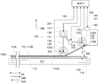
이미징된 도너 요소(112)는 단계(330)에서 기판(110)으로부터 제거된다. 이 예시적인 실시예에서, 도너 요소(112)는 접촉 롤러(130)가 이미징된 영역(112B)을 가로질러 에지 부분(115B) 근처의 이미징되지 않은 영역(112A)으로 롤링한 이후 제거된다. 도 2에 도시되어 있는 바와 같이, 신호(135)는 테이크-업 롤러 축-위치 액추에이터(133)가 테이크-업 롤러(132)를 이미징된 도너 요소(112) 근처로 이동시키도록 한다. 바람직하게, 테이크-업 롤러(132)는 접촉 롤러(130)의 위치보다는 이미징된 영역(112B)으로부터 멀리 떨어진 위치에서 도너 요소(112)의 이미징되지 않은 영역(112A) 근처로 이동한다. 이 예시적인 실시예에서, 테이크-업 롤러(132)는 이미징되지 않은 영역(112A)의 부분(113) 근처로 이동한다. 현재 바람직한 실시예에서, 테이크-업 롤러(132)는 적어도 부분적으로 스탠드(118)를 오버레이하는 위치에서의 부분(113) 근처로 이동한다. 몇몇 실시예에서, 테이크-업 롤러(132)는 도너 요소(112)를 기판(110)에 고정시키는 흡입 피처(120)보다 기판(110)의 에지로부터 멀리 떨어진 위치에서의 이미징되지 않은 영역(112A) 근처로 이동한다.The imaged
테이크-업 롤러(132)가 도너 요소(112)와 접촉하는 경우, 제어기(108)는 신호(145)를 사용하여 흡입원(143)이 흡입 피처(134)를 통해 흡입하게 한다. 흡입 피처(143)를 통한 흡입 인가는 이미징되지 않은 영역(112A)의 일부분(에지 부분(115B)을 포함함)이 테이크-업 롤러(132)에 부착되도록 한다(즉, 흡입 피처(134)는 이미징되지 않은 영역(112A)의 일부분을 테이크-업 롤러(132)에 고정한다). 몇몇 실시예에서, 테이크-업 롤러(132)는 이미징되지 않은 영역(112A)의 도너 요소(112)와 접촉하고 도너 요소(112)를 테이크-업 롤러(132)에 고정시키도록 흡입이 직접 인가된다. 또 다른 실시예에서, 테이크-업 롤러(132)는 흡입이 인가되기 전에 도너 요소(112)와 접촉할 필요는 없다. 이러한 실시예에서, 흡입 피처(134)를 통해 흡입이 인가되는 경우, 도너 요소(112)의 일부분은 테이크-업 롤러(132)에 고정되기 전에 이 테이크-업 롤러(132) 쪽으로 당겨질 수 있다. 몇몇 실시예에서, 제어기(108)는 흡입 피처(134)를 통한 흡입의 인가 전에 또는 그 동안 흡입 피처(120)에 의해 인가되는 흡입을 중단 또는 감소시킬 수 있다.When take-up
소정의 실시예에서, 흡입 피처(134)는 테이크-업 롤러(132)의 원통형 표면 상에서의 하나 이상의 알려진 위치에 위치한다. 이러한 실시예에서, 제어기(108)는 바람직하게 신호(141)를 사용하여 테이크-업 롤러 회전 액추에이터(139)를 "위치 모드"로 동작시킨다. 위치 모드 동작에서, 제어기(108)는 원하는 위치를 달성하도록 액추에이터(139)가 테이크-업 롤러(132)를 임의의 속도(그의 제어가능한 속도 범위 내에서)로 이동시키게 하는 제어 기법을 사용한다. 도 2d에 도시되어 있는 바와 같이, 테이크-업 롤러(132)의 바람직한 위치는 흡입 피처(134)가 도너 요소(112)에 가깝게 위치하게 되는 위치이다. 예시적인 실시예에서, 테이크-업 롤러(132)는 원통형 표면 상에서 하나의 원주 위치에서만 흡입 피처를 갖는 것으로 도시되어 있다. 당업자라면, 다른 실시예에서, 테이크-업 롤러(132)는 원통형 표면 상에서 다수의 원주 위치에서 흡입 피처를 포함할 수 있음을 알 수 있을 것이다.In certain embodiments, the
도 2e는 도너 요소(112)의 에지 부분(115B)이 테이크-업 롤러(132)의 원통형 표면 상에 고정되면, 제어기(108)는 신호(135)를 사용하여 테이크-업 롤러 축-위치 액추에이터(133)가 테이크-업 롤러(132)를 기판(110)으로부터 멀어지게(즉, 적어도 화살표(146)의 방향 내의 구성요소를 갖는 방향으로) 이동시키도록 한다. 도 2d 및 도 2e를 비교함으로써 알 수 있는 바와 같이, 테이크-업 롤러 축-위치 액추에이터(133)는 섀시(136) 및 접촉 롤러(130)에 대한 테이크-업 롤러(132)의 상대적 이동을 야기하되 섀시(136) 및 접촉 롤러(130)는 동일한 위치로 유지된다. 테이크-업 롤러(132)가 이러한 방식으로 이동하는 경우 도너 요소(112)의 에지 부분(115B) 및 소정의 이미징되지 않은 영역(112A)은 지지대(101)로부터 멀어지는 방향으로 이동한다. 2E shows that when the
도 2e에 도시되어 있는 바와 같이, 접촉 롤러(130)는 바람직하게 도너 요소(112)와 접촉한 채로 유지되고 그에 대항하는 힘을 발휘할 수 있다. 따라서, 접촉 롤러(130)의 일 측면(즉, 테이크-업 롤러(132)로부터 멀어지는 측면) 상의 도너 요소(112)의 일부분은 기판(110)과 접촉한 채로 유지되는 한편, 접촉 롤러(130)의 반대 측면(즉, 테이크-업 롤러(132)와 동일한 측면) 상의 도너 요소(112)의 일부분은 기판(110)으로부터 필링되고 접촉 롤러(130)의 원주 표면 주위를 따라 휘어진다. 접촉 롤러(130)의 특성(즉, 그의 원주 표면을 형성하는 직경 및/또는 물질) 및/또는 접촉 롤러(130)가 도너 요소(112)와 접촉하는 방식의 특성(예를 들어, 이러한 접촉의 힘 및/또는 압력)은 필링 직전에 도너 요소(112)와 기판(110) 간의 실효 접촉 면적을 제어하는데 사용될 수 있다. 몇몇 실시예에서, 접촉 롤러(130)와 도너 요소(112) 간의 실효 면적은 접촉 롤러(130)의 원주 표면적의 10% 미만이다. 다른 실시예에서, 이 비율은 5% 미만이다. 몇몇 실시예에서, 접촉 롤러(130)와 도너 요소(112) 사이에 인가되는 힘은 접촉 롤러(130)에 작용하는 중력보다 작다(즉, 섀시(136)가 접촉 롤러(130)의 중량의 일부를 지탱함).As shown in FIG. 2E, the
기판(110)으로부터 멀어지는 테이크-업 롤러(132)의 이동은 또한 기판(110)에 대해 접선인 하나 이상의 방향에 따른 테이크-업 롤러(132)의 이동을 또한 포함할 수 있다. 예를 들어, 테이크-업 롤러 축 위치 액추에이터(133)는 테이크-업 롤러(132)가 곡선 경로를 따라 이동하게 한다. 기판(110)으로부터 멀어지는 테이크-업 롤러(132)의 이동 동안, 제어기(108)는 신호(141)를 사용하여 테이크-업 롤러 회전 액추에이터(139)가 그의 축(132A)을 중심으로 테이크-업 롤러(132)를 선회(pivot)시키도록 한다. 이러한 테이크-업 롤러(132)의 선회 움직임은 기판(110)으로부터 필링된 이미징된 도너 요소(112)의 일부분의 느슨함을 팽팽하게 하거나 또는 이미징된 도너 요소(112)의 이 부분에 대한 바람직한 팽창력을 유지하는데 사용될 수 있다. 이 기간 동안, 제어기(108)는 신호(141)를 사용하여 테이크-업 롤러 회전 액추에이터(139)를 "토크 모드(torque mode)"로 제어한다. 토그 모드 동작에서, 제어기(108)는 바람직한 토크를 추적하기 위해 액추에이터(139)가 테이크-업 롤러(132)를 임의의 속도(그의 제어가능 속도 범위)로 이동시키게 하는 제어 기법을 사용한다.Movement of the take-up
테이크-업 롤러 축-위치 액추에이터(133)에 의한 테이크-업 롤러(132)의 이동량은 바람직한 필링 각도(θ)를 달성하기 위해 변동될 수 있음을 당업자라면 알 수 있을 것이다. 예시적인 실시예에서, 접촉 롤러(130) 및 테이크-업 롤러(132)가 실질적으로 동일한 크기를 갖는 경우, 필링 각도(θ)는 롤러(130,132)의 회전축(130A,132A) 간의 각도와 동일할 것이다. 몇몇 실시예에서, 필링 각도(θ)는 어도 부분적으로 매체(즉, 도너 물질, 기판(110) 및 도너 요소(112))에 따라 삼십(30)도 미만이다. 현재의 바람직한 실시예에서, 필링 각도(θ)는 오(5)도 미만이다.It will be appreciated by those skilled in the art that the amount of travel of the take-up
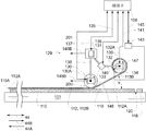
다음으로, 도 2f에 도시되어 있는 바와 같이, 제어기(108)는 신호(137)를 사용하여 섀시 위치 액추에이터(131)가 섀시(136)(롤러(130,132)를 포함함)를 화살표(148B) 방향으로 이동시키도록 하고 신호(141)를 사용하여 테이크-업 롤러 회전 액추에이터(139)가 섀시(136) 및 지지대(101)에 대해 테이크-업 롤러(132)를 화살표(147)의 방향으로 동시에 회전시키게 한다. 섀시(136)의 이러한 동시 이동 및 테이크-업 롤러(132)의 회전은 도너 요소를 접촉 롤러(130) 주위로 끌어당기고 도너 요소(112)를 기판(110)으로부터 필링된다. 접촉 롤러(130)는 이미징된 도너 요소(112) 상에서 필링 방향(즉, 화살표(148A)의 방향)을 따라 롤링되는 경우 화살표(146)의 방향으로 회전한다. 도 2f에 도시되어 있는 바와 같이, 이 회전은 접촉 롤러(130)의 회전축(130A)이 화살표(148B)의 방향을 따라 이동하게 한다. 이 예시적인 실시예에서, 화살표(148B)의 방향은 접촉 롤러(130)가 단계(320)에서 롤링된 화살표(148A)의 방향과는 반대이다. 이 예시적인 실시예에서, 단계(330) 동안 접촉 롤러(130)의 이동과 연관된 필링 방향은 단계(320) 동안 접촉 롤러(130)의 이동과 연관된 롤링 방향과 반대이다. Next, as shown in FIG. 2F, the
바람직하게, 이러한 시트 필링 프로세스 동안, 제어기(108)는 신호(141)를 사용하여 테이크-업 롤러 회전 액추에이터(139)를 "토크 모드"로 동작시키는데, 이 토크 코드에서 제어기(108)는 바람직한 토크를 달성하기 위해 테이크-업 롤러(132)를 임의의 속도(그의 제어가능한 속도 범위 내에서)로 회전시킨다. 테이크-업 롤러 회전 액추에이터(139)가 토크 모드에서 이 바람직한 토크를 추적하도록 동작하는 경우, 도너 요소(112)에 대한 필링 장력은 바람직한 필링 장력에 비교적 근접하게 유지된다. 또 다른 실시예에서, 제어기(108)는 섀시(136)의 병진 위치와 동기화되는 위치를 추적하기 위해 신호(141)를 사용하여 테이크-업 롤러 회전 액추에이터(139)를 "위치 모드"로 동작시킨다. Preferably, during this seat peeling process, the
테이크-업 롤러(132)가 화살표(147)의 방향으로 회전하고 화살표(148B)의 방향으로 병진하는 경우, 도너 요소(112)는 테이크-업 롤러(132)에 의해 "스풀링 업(spooled up)"된다(즉, 테이크-업 롤러(132)의 원통형 표면을 휘감는다). 접촉 롤러(130)는 기판(110) 상에 여전히 존재하는 도너 요소(112)의 부분과 접촉을 유지하고 도너 요소(112)에 대항하는 힘을 인가할 수 있다. 위에서 설명한 바와 같이, 예시적인 실시예에서, 접촉 롤러(130)는 아이들러 롤러이다. 접촉 롤러(130)는 도너 요소(112)가 기판(110)으로부터 너무 이르게 분리되는 것을 방지하고 도너 요소(112)가 원하는 필링 각도(θ)에서 기판(110)으로부터 분리되도록 보장한다.When take-up
본 발명의 예시적인 실시예에서, 브레이크(200)는 단계(320)에 대응하는 포스트 이미징 롤링 시퀀스 동안보다 이미징된 도너 요소(112)를 기판(110)으로부터분리 및 제거하는 동안 접촉 롤러가 이미징된 도너 요소(112)의 표면 상에 롤링하는 경우 접촉 롤러(130)에 서로 다른 양의 제동을 인가하도록 제어된다. 즉, 접촉 롤러(130)의 회전축(130A)과 이미징된 도너 요소(112) 및 지지대(101) 간의 다수의 상대적 이동이 수행되어 접촉 롤러가 이미징된 영역(112B) 상에서 여러번(즉, 단계(320 및 330)에서) 롤링하게 된다. 다수의 상대적 이동 중 하나 동안, 도너 요소(112)는 전술한 필링 방법에 의해 기판(110)으로부터 제거되었다. 이 예시적인 실시예에서, 브레이크(200)는 각각의 상대적 이동 동안 접촉 롤러(130)에 상이한 양의 제동을 인가하도록 선택적으로 제어되었다. 선택적으로 인가되는 제동의 상이한 양은 단계(320)에서 인가된 제동의 양보다 큰 또는 작은 양의 제동을 포함할 수 있다. 본 발명의 예시적인 실시에에서, 브레이크(200)는 단계(320)보다는 단계(330) 동안에 보다 적은 양의 제동을 인가하도록 제어된다. 이 실시예에서, 기판(110)으로부터 도너 요소(112)를 제거하는 동안 브레이크(200)에 의해 사실상 어떠한 추가의 제동도 접촉 롤러(130)에 인가되지 않았다. 그러나, 브레이크(200)는 구동되지 않았더라도 소정 형태의 최소의 제동을 제공할 수 있음을 주목해야 한다. 브레이크(200)는 접촉 롤러(130)에 대한 지속기간을 변경하기 위해 변동되는 양의 제동을 인가하도록 구동될 수 있고 이들 양 및 지속기간은 접촉 롤러(130)를 포함하는 애플리케이션의 요건에 따라 달라질 수 있다. 브레이크(200)는 접촉 롤러(130)가 롤링되는 경로를 따라 다양한 위치에서 상이한 양의 제동을 접촉 롤러(130)에 선택적으로 인가하도록 제어될 수 있다.In an exemplary embodiment of the invention, the
시트 필링 동작 동안 접촉 롤러(130) 및 테이크-업 롤러(132)의 동시 회전 및 병진은 또한 "프린트 스루(print through)" 효과를 방지한다. 프린트 스루 효과는 롤러가 기저 기판으로부터 도너 요소를 필링하도록 병진하는 경우 도너 요소가 롤러 주위를 래핑할 때 발행할 수 있다(도 1a 참조). 매체 에지는 무시하지 못할 두께를 가질 수 있기 때문에, 초기에 롤러에 고정된 매체의 에지로 인해 필링되지 않은 도너 요소의 일부분은 고정된 에지가 롤링되는 경우 불연속을 나타낼 수 있다. 테이크-업 롤러(132)는 기판(110)으로부터 이격되기 때문에, 기판(110) 상으로 전해진 이미지는 테이크-업 롤러(132) 상에 감겨진 도너 시트(112)의 부분이 에지 부분(115B)을 오버랩하는 경우에 영향을 받지 않는다. 도너 요소(112)의 에지 부분(115B)에 의해 야기된 두께 변동은 기판(110) 상에 전해진 이미지에 영향을 미치지 않는다.Simultaneous rotation and translation of the
접촉 롤러(130)는 도너 요소(112)의 에지 부분(115A)을 접근하는 경우, 제어기(108)는 신호(137)를 사용하여 섀시-위치 액추에이터(131)가 섀시(136)를 도너 요소(112)로부터 멀어지게 이동시키게 하고 신호(141)를 사용하여 테이크-업 롤러 회전 액추에이터(139)가 도너 요소(112)의 "말단(tail)"을 팽팽하게 하도록 테이크-업 롤러(132)를 회전시키게 한다. 제어기(108)는 도너 요소(112)의 이 부분을 제거 하는 동안 위치 모드로 테이크-업 롤러 회전 액추에이터(139)를 동작시킬 수 있다. When the
도너 요소(112)가 기판(110)으로부터 제거되면, 제 2 도너 요소(112)(예를 들어, 다른 컬러의 도너 요소(112))가 기판(110) 상에 배치될 수 있고 본 발명이 제시한 것과 유사한 방식이 이용되어 제 2 도너 요소(112)를 더 이미징하고 이미징되었으면 이 제 2 도너 요소(112)를 제거할 수 있다. 예시적인 실시예에서, 기판(110)은 단계(340)에서 지지대(101)로부터 제거된다. 도너 요소 제거 장치(129)는 지지대(101)로부터 기판(110)을 제거할 필요는 없는데, 그 이유는 당업계에 알려져 있는 다른 메카니즘이 사용될 수 있기 때문이다. 본 발명의 예시적인 실시예에서, 기판(110)은 접촉 롤러가 이미징된 영역(112B) 상에서 여러번 롤링하도록 인에이블링된 접촉 롤러(130)의 회전축(130A)과 이미징된 도너 요소(112) 간의 다수의 상대적 이동 중 어떠한 이동 중에서도 지지대(101)로부터 제거되지 않는다.Once the
기판(110)으로부터 이미징된 도너 요소(112)를 제거하기 전에 이미징된 도너 요소(11)를 "사전 롤링하는 동작"이 사용되어 도너 요소(112)가 기판(110)으로부터 제거될 때 발생할 수 있는 아티팩트를 감소킬 수 있다. 특히, 이미징된 도너 요소(112)가 기판으로부터 필링되는 경우 기판(110)의 표면으로 전달되어 유지되는 도너 물질의 양은 이를 제거하기 전에 이미징된 도너 요소(112) 상에 접촉 롤러(130)를 사전 롤링함으로써 조정될 수 있다. 에지 불연속과 같은 아티팩트는 기판의 표면에 전달되어 유지되는 도너 물질의 양의 이러한 조정에 의해 감소될 수 있다. 이와 관련하여, 본 발명자는 기판(110)의 특정 영역으로 전달되려 하는 도너 물질의 양 및 분포의 변화는 특히 특정 영역이 기판(110)상에 형성된 피처의 에지 부분 근처에 있는 경우 기판(110)으로부터 제거하기 전에 도너 요소(112) 상에 접촉 롤러(130)를 롤링함으로써 감소될 수 있다.Before removing the imaged
이 예시적인 실시예에서, 사전 롤링 단계 및 필링 단계 모두에서 동일한 접촉 롤러(130)가 사용되었지만, 당업자라면 이들 단계 각각에서 상이한 롤링 부재가 사용될 수 있다는 것을 신속하게 확인할 수 있을 것이다. 접촉 롤러(130)는 본 발명의 사전-롤링 측면에만 전용된 기능을 갖는 롤러를 포함할 수 있다.In this exemplary embodiment, the
본 발명의 다양한 실시예는 다양한 디스플레이에 대한 컬러 필터를 제조하는 것과 관련하여 설명되었다. 본 발명의 일부 예시적인 실시예에서, 디스플레이는 LCD 디스플레이일 수 있다. 본 발명의 또 다른 예시적인 실시예에서, 디스플레이는 유기 발광 다이오드(OLED) 디스플레이일 수 있다. OLED 디스플레이는 상이한 구성을 포함할 수 있다. 예를 들어, LCD 디스플레이와 유사한 방식으로, 상이한 컬러의 피처가 백색 OLED 소스와 연계하여 사용되는 컬러 필터 내에 형성될 수 있다. 이와 달리, 디스플레이 내의 상이한 컬러 조명 소스는 본 발명의 다양한 실시예에서 상이한 OLED 물질을 이용하여 형성될 수 있다. 이들 실시예에서, OLED 기반 조명 소스는 수동 컬러 필터를 반드시 필요로 하는 일 없이 컬러 광의 방출을 스스로 제어한다. OLED 물질은 적절한 매체로 전달될 수 있다. OLED 물질은 레이저 유도 열 전사 기법을 통해 수신 요소로 전달될 수 있다.Various embodiments of the present invention have been described with reference to manufacturing color filters for various displays. In some exemplary embodiments of the invention, the display may be an LCD display. In another exemplary embodiment of the invention, the display may be an organic light emitting diode (OLED) display. OLED displays can include different configurations. For example, in a manner similar to LCD displays, features of different colors can be formed in color filters used in conjunction with white OLED sources. Alternatively, different color illumination sources within the display may be formed using different OLED materials in various embodiments of the present invention. In these embodiments, OLED based illumination sources control the emission of color light by themselves without necessarily requiring a passive color filter. OLED materials can be transferred to a suitable medium. OLED material can be delivered to the receiving element via a laser induced thermal transfer technique.
본 발명은 예를 들어 디스플레이 및 전자 장치 제조에서의 애플리케이션을 이용하여 설명되었지만, 본 명세서에서 기술된 방법은 LOC(lab-on-a-chip) 제조를 위한 생물의학 이미징에 사용되는 것을 포함하여 다른 애플리케이션에도 직접 적용될 수 있다. 본 발명은 의료, 인쇄 및 전자 제조 기술과 같은 다른 기술에도 적용될 수 있다.Although the present invention has been described using, for example, applications in display and electronic device manufacturing, the methods described herein may be used in other applications, including those used for biomedical imaging for lab-on-a-chip (LOC) manufacturing. It can also be applied directly to the application. The invention is also applicable to other technologies such as medical, printing and electronic manufacturing techniques.
본 발명은 특히 소정의 바람직한 실시예를 참조하여 자세히 기술되었지만, 본 발명의 사상 및 범주 내에서 변형 및 수정이 이루어질 수 있음이 이해될 것이다.Although the invention has been described in detail with reference to certain preferred embodiments, it will be understood that variations and modifications may be made within the spirit and scope of the invention.
참조 부호reference mark
10 : 기판10: substrate
12 : 도너 요소12: donor element
12A : 에지12A: Edge
14 : 레이저14: laser
16 : 레이저 빔16: laser beam
18 : 롤러18: roller
18A : 원주 표면18A: circumferential surface
19 : 화살표19: arrow
20 : 흡입 피처20: suction feature
22 : 화살표22: arrow
24 : 화살표24: arrow
25 : 이미징된 영역25: imaged area
25A : 이미징된 에지25A: Imaged Edge
25B : 에지25B: Edge
27 : 이미징되지 않은 영역27: non-imaging area
42 : 주 스캔 축42: main scan axis
42A : 전방향42A: Omnidirectional
42B : 역방향42B: reverse
44 : 서브-스캔 축44: sub-scan axis
44A : 멀어지는 방향44A: away
44B : 가까워지는 방향44B: Closer Direction
100 : 장치100: device
101 : 지지대101: support
102 : 이미징 헤드102: Imaging Head
103 : 이미징 전자장치103: imaging electronics
104 : 이미징 데이터104: Imaging Data
105 : 지지대105: support
108 : 제어기108: controller
109 : 움직임 시스템109: movement system
110 : 기판110: substrate
110A : 이미징되지 않은 영역110A: Unimaged Area
110B : 이미징된 영역110B: imaged area
112A : 이미징되지 않은 영역112A: Unimaged Area
112B : 이미징된 영역112B: imaged area
113 : 부분113: part
114 : 채널114: channel
115A : 도너 요소 에지 부분115A: Donor Element Edge Part
115B : 도너 요소 에지 부분115B: Donor Element Edge Part
116 : 방사 빔116: radiation beam
118 : 스탠드118: stand
120 : 흡입 피처120: suction feature
122 : 공간122: space
129 : 시트 제거 장치129: sheet removing device
130 : 접촉 롤러130: contact roller
130A : 회전축130A: axis of rotation
131 : 섀시-위치 액추에이터131: Chassis-Position Actuator
132A : 회전축132A: axis of rotation
132 : 테이크-업 롤러132: take-up roller
133 : 테이크-업 롤러 축-위치 액추에이터133: Take-up Roller Shaft-Position Actuator
134 : 흡입 피처134: suction feature
135 : 신호135: signal
136 : 섀시136: chassis
137 : 신호137: signal
138 : 접촉 롤러 커를링138: Contact Roller Curling
139 : 테이크-업 롤러 회전 액추에이터139: Take-Up Roller Rotary Actuator
140 : 테이크-업 롤러 커플링140: take-up roller coupling
141 : 신호141: signal
143 : 흡입원143: suction source
144 : 화살표144: arrow
145 : 신호145: signal
146 : 화살표146: arrow
147 : 화살표147: arrow
148A : 화살표148A: Arrow
148B : 화살표148B: Arrows
170 : 영역170: area
171 : 지점171: branch
200 : 브레이크200: brake
201 : 신호201: signal
300 : 단계300: step
310 : 단계310: step
320 : 단계320: step
330 : 단계330: step
340 : 단계340: step
W : 부하W: load
P : 힘P: force
M : 커플M: Couple
b : 롤링 저항 계수b: rolling resistance coefficient
R : 반동력R: reaction force
f1 : 마찰력f1: frictional force
f : 계면력f: interfacial force
r : 반지름r: radius
θ : 필링 각도θ: peeling angle
Claims (51)
기판 및 상기 매체를 층형 구성(layered configuration)으로 지탱하도록 구성된 지지대를 제공하는 단계와,
이미징 헤드와 상기 지지대 간의 상대적 이동을 발생시키면서 이미징된 매체의 표면 쪽으로 방사 빔을 유도함으로써 상기 매체를 이미징하도록 이미징 헤드를 동작시키는 단계와,
회전축을 중심으로 회전가능한 롤러를 상기 이미징된 매체와 접촉시키는 단계와,
상기 롤러의 회전축과 상기 지지대 간의 상대적 이동을 발생시켜 상기 방사 빔이 가해진 상기 이미징된 매체의 표면의 영역 상에 상기 롤러가 롤링하도록 하는 단계와,
상기 방사 빔이 가해진 상기 이미징된 매체의 표면의 영역 상에 상기 롤러를 롤링한 이후 상기 기판으로부터 상기 이미징된 매체를 제거하는 단계를 포함하는
매체를 이미징하는 방법.
A method of imaging a medium,
Providing a support configured to support a substrate and the medium in a layered configuration;
Operating the imaging head to image the medium by directing a radiation beam towards the surface of the imaged medium while generating a relative movement between the imaging head and the support;
Contacting the rotatable roller about the axis of rotation with the imaged medium;
Generating relative movement between the axis of rotation of the roller and the support to cause the roller to roll on an area of the surface of the imaged medium to which the radiation beam is applied;
Removing the imaged medium from the substrate after rolling the roller on an area of the surface of the imaged medium to which the radiation beam has been applied;
Method of imaging the medium.
상기 이미징된 매체가 상기 기판으로부터 제거된 이후, 상기 방법은,
추가의 매체 및 상기 기판을 상기 지지대 상에 지탱하는 단계와,
상기 이미징 헤드와 상기 지지대 간의 상대적 이동을 발생시키면서 상기 추가의 매체를 이미징하는 단계와,
상기 롤러의 회전축과 상기 지지대 간의 상대적 이동을 발생시키면서 상기 기판으로부터 상기 이미징된 추가의 매체를 제거하는 단계를 더 포함하는
매체를 이미징하는 방법.
The method of claim 1,
After the imaged medium is removed from the substrate, the method further comprises:
Supporting additional media and the substrate on the support;
Imaging the additional medium while generating relative movement between the imaging head and the support;
Removing the imaged additional medium from the substrate while generating a relative movement between the axis of rotation of the roller and the support;
Method of imaging the medium.
상기 롤러는 상기 이미징된 매체의 표면의 이미징되지 않은 영역과 접촉하고, 상기 이미징되지 않은 영역은 상기 방사 빔이 가해지지 않은 상기 이미징된 매체의 표면의 영역에 대응하는
매체를 이미징하는 방법.
The method of claim 1,
The roller contacts a non-imaged area of the surface of the imaged medium, the unimaged area corresponding to an area of the surface of the imaged medium on which the radiation beam is not applied.
Method of imaging the medium.
상기 이미징되지 않은 영역은 상기 매체의 에지 부분을 포함하고, 상기 롤러의 회전축과 상기 지지대 간의 상대적 이동의 발생은 상기 롤러가 상기 에지 부분으로부터 멀어지는 방향을 따라 상기 이미징된 매체의 표면상에 롤링하게 하는
매체를 이미징하는 방법.The method of claim 3, wherein
The non-imaged area includes an edge portion of the medium, and the occurrence of relative movement between the axis of rotation of the roller and the support causes the roller to roll on the surface of the imaged medium along a direction away from the edge portion.
Method of imaging the medium.
상기 롤러는 아이들러 롤러(idler roller)인
매체를 이미징하는 방법.
The method of claim 1,
The roller is an idler roller
Method of imaging the medium.
상기 기판으로부터 상기 이미징된 매체를 제거하는 단계는 상기 이미징된 매체를 상기 기판으로부터 필링하는 단계를 포함하는
매체를 이미징하는 방법.
The method of claim 1,
Removing the imaged media from the substrate includes filling the imaged media from the substrate.
Method of imaging the medium.
상기 롤러의 회전축과 상기 지지대 간의 추가의 상대적 이동을 발생시켜 상기 롤러가 상기 이미징된 매체의 표면의 일부분 상에 롤링하게 하면서 상기 이미징된 매체를 상기 기판으로부터 제거하는 단계를 포함하는
매체를 이미징하는 방법.
The method according to claim 6,
Removing the imaged media from the substrate while generating additional relative movement between the axis of rotation of the roller and the support to cause the roller to roll on a portion of the surface of the imaged media.
Method of imaging the medium.
상기 이미징된 매체를 상기 기판으로부터 필링하면서 상기 롤러의 원통형 표면의 일부분 위에 상기 이미징된 매체의 일부분을 래핑(wrapping)하는 단계를 포함하는
매체를 이미징하는 방법.
The method according to claim 6,
Wrapping the portion of the imaged medium over the portion of the cylindrical surface of the roller while peeling the imaged medium from the substrate.
Method of imaging the medium.
상기 이미징된 매체의 표면 상에 롤링하도록 구성된 접촉 롤러를 제공하는 단계를 포함하되, 상기 방법은 상기 이미징된 매체를 상기 기판으로부터 필링하면서 상기 접촉 롤러의 원통형 표면의 일부분 위에 상기 이미징된 매체의 일부분을 래핑하는 단계를 더 포함하는
매체를 이미징하는 방법.
The method according to claim 6,
Providing a contact roller configured to roll on the surface of the imaged medium, the method comprising: placing a portion of the imaged medium over a portion of the cylindrical surface of the contact roller while filling the imaged medium from the substrate; Further comprising the step of wrapping
Method of imaging the medium.
상기 매체의 표면 상에 테이크-업 롤러(take-up roller)를 롤링하지 않으면서 상기 이미징된 매체의 일부분을 스풀링(spool)하도록 구성된 테이크-업 롤러를 제공하는 단계를 포함하되, 상기 방법은 상기 이미징된 매체를 상기 기판으로부터 제거하면서 상기 이미징된 매체의 일부분을 상기 테이크-업 롤러 상에 스풀링하는 단계를 더 포함하는
매체를 이미징하는 방법.
The method of claim 1,
Providing a take-up roller configured to spool a portion of the imaged medium without rolling a take-up roller on the surface of the medium, the method comprising: Spooling a portion of the imaged medium onto the take-up roller while removing the imaged medium from the substrate;
Method of imaging the medium.
상기 롤러의 회전축과 상기 지지대 간의 상대적 이동을 발생시켜 상기 방사 빔이 가해진 상기 이미징된 매체의 표면 상에서의 롤링 방향에 따라 상기 롤러가 롤링하게 하는 단계와,
상기 접촉 롤러와 상기 지지대 간의 상대적 이동을 발생시켜 상기 접촉 롤러가 상기 이미징된 매체의 표면의 일부분 상에서 필링 방향(peeling direction)을 따라 롤링하게 하면서 상기 기판으로부터 상기 이미징된 매체를 필링하는 단계를 더 포함하되, 상기 필링 방향은 상기 롤링 방향에 실질적으로 평행한
매체를 이미징하는 방법.
The method of claim 9,
Generating relative movement between the axis of rotation of the roller and the support to cause the roller to roll in accordance with the rolling direction on the surface of the imaged medium to which the radiation beam is applied;
Filling the imaged media from the substrate while generating a relative movement between the contact roller and the support to cause the contact roller to roll along a peeling direction on a portion of the surface of the imaged media. Wherein the peeling direction is substantially parallel to the rolling direction
Method of imaging the medium.
상기 롤링 방향 및 상기 필링 방향은 반대 방향인
매체를 이미징하는 방법.
The method of claim 11,
The rolling direction and the peeling direction are opposite directions
Method of imaging the medium.
상기 이미징 헤드는 스캔 방향을 따라 상기 이미징된 매체의 표면 위를 상기방사 빔으로 스캐닝함으로써 상기 매체를 이미징하도록 동작하고,
상기 방법은 상기 롤러의 회전축과 상기 지지대 간의 상대적 이동을 발생시켜 상기 방사빔이 가해진 상기 이미징된 매체의 표면의 영역 상에서 상기 롤러가 스캔 방향에 실질적으로 평행한 롤링 방향을 따라 롤링하게 하는 단계를 더 포함하는
매체를 이미징하는 방법.
The method of claim 1,
The imaging head is operative to image the medium by scanning the radiation beam onto the surface of the imaged medium along a scan direction,
The method further comprises generating a relative movement between the axis of rotation of the roller and the support to cause the roller to roll along a rolling direction substantially parallel to the scan direction on an area of the surface of the imaged medium to which the radiation beam is applied. Containing
Method of imaging the medium.
상기 지지대와 상기 이미징 헤드 중 하나를 운반 방향을 따라 이동시키면서 상기 매체를 이미징하는 단계를 포함하되, 상기 롤러의 회전축과 상기 지지대 간의 상대적 이동의 발생은 상기 방사빔이 가해진 상기 이미징된 매체의 표면의 영역 상에서 상기 롤러가 상기 운반 방향에 실질적으로 평행한 롤링 방향을 따라 롤링하게 하는
매체를 이미징하는 방법.
The method of claim 1,
Imaging the medium while moving one of the support and the imaging head along a conveying direction, wherein the occurrence of relative movement between the axis of rotation of the roller and the support is dependent upon the surface of the imaged medium to which the radiation beam has been applied. Allowing the roller on the area to roll along a rolling direction substantially parallel to the conveying direction
Method of imaging the medium.
상기 이미징된 매체의 표면의 일부분 상에 상기 롤러가 롤링하는 동안 상기 롤러에 제동(drag)을 선택적으로 인가하는 단계를 포함하는
매체를 이미징하는 방법.
The method of claim 1,
Selectively applying a drag to the roller while the roller is rolling on a portion of the surface of the imaged media
Method of imaging the medium.
상기 이미징된 매체의 표면의 일부분 상에 상기 롤러가 롤링하는 동안 상기 롤러에 제동을 선택적으로 인가하도록 구성된 브레이크를 제공하는 단계를 포함하는
매체를 이미징하는 방법.
The method of claim 1,
Providing a brake configured to selectively apply braking to the roller while the roller is rolling on a portion of the surface of the imaged media;
Method of imaging the medium.
상기 브레이크는 자기 입자 브레이크 및 히스테리시스 브레이크 중 하나인
매체를 이미징하는 방법.
17. The method of claim 16,
The brake is one of magnetic particle brake and hysteresis brake
Method of imaging the medium.
상기 매체는 도너 요소(donor element)이고, 상기 방법은 상기 도너 요소로부터 상기 기판으로 도너 물질을 전달하여 상기 기판 상에 스트라이프 피처(striped feature)를 형성하기 위해 상기 도너 요소 쪽으로 상기 방사 빔을 유도하도록 상기 이미징 헤드를 동작시키는 단계를 더 포함하되, 상기 스트라이프 피처는 상기 롤러의 회전축과 상기 지지대 간의 상대적 이동을 발생시켜 상기 방사 빔이 가해진 상기 매체의 표면의 영역 상에서 상기 롤러가 롤링하는 동안 상기 롤러가 상기 이미징된 매체의 표면 상에서 롤링하는 방향에 실질적으로 평행한 방향을 따라 연장하는
매체를 이미징하는 방법.
The method of claim 1,
The medium is a donor element and the method transfers donor material from the donor element to the substrate to direct the radiation beam towards the donor element to form a striped feature on the substrate. Operating the imaging head, wherein the stripe feature generates a relative movement between the axis of rotation of the roller and the support such that the roller is rolled over the area of the surface of the medium to which the radiation beam is applied. Extending along a direction substantially parallel to the rolling direction on the surface of the imaged media
Method of imaging the medium.
상기 기판으로부터 상기 이미징된 매체를 제거한 이후 상기 지지대로부터 상기 기판을 제거하는 단계를 포함하는
매체를 이미징하는 방법.
The method of claim 1,
Removing the substrate from the support after removing the imaged media from the substrate.
Method of imaging the medium.
기판 및 상기 매체를 층형 구성으로 지탱하도록 구성된 지지대를 제공하는 단계와,
상기 매체와 상기 기판을 상기 층형 구성으로 유지하면서 상기 매체 쪽으로 방사 빔을 방출하여 상기 매체를 이미징하도록 이미징 헤드를 동작시키는 단계와,
상기 이미징된 매체의 표면에 롤러를 접촉시키는 단계와,
상기 이미징된 매체의 표면 상에 상기 롤러를 롤링하는 동안 상기 롤러에 제동을 선택적으로 인가하는 단계와,
상기 이미징된 매체를 상기 기판으로부터 제거하는 단계를 포함하는
매체를 이미징하는 방법.
A method of imaging a medium,
Providing a support configured to support a substrate and the media in a layered configuration;
Operating an imaging head to emit the radiation beam towards the medium while imaging the medium while maintaining the medium and the substrate in the layered configuration;
Contacting a roller to the surface of the imaged medium;
Selectively applying braking to the rollers while rolling the rollers on the surface of the imaged media;
Removing the imaged medium from the substrate.
Method of imaging the medium.
상기 이미징된 매체의 표면 상에 상기 롤러를 롤링하는 동안 상기 롤러에 회전 제동을 선택적으로 인가하는 단계를 포함하는
매체를 이미징하는 방법.
The method of claim 20,
Selectively applying rotary braking to the roller while rolling the roller onto the surface of the imaged media
Method of imaging the medium.
상기 롤러에 동작가능하게 접속된 브레이크를 제공하는 단계를 포함하되, 상기 브레이크는 상기 이미징된 매체의 표면 상에 상기 롤러를 롤링하는 동안 상기 롤러에 제동을 선택적으로 인가하도록 구성된
매체를 이미징하는 방법.
The method of claim 20,
Providing a brake operably connected to the roller, the brake configured to selectively apply braking to the roller while rolling the roller on a surface of the imaged medium
Method of imaging the medium.
상기 이미징된 매체의 표면 상에 상기 롤러를 롤링하는 동안 상기 롤러에 회전 제동을 선택적으로 인가하도록 액추에이터를 선택적으로 가동시키는 단계를 포함하는
매체를 이미징하는 방법.
The method of claim 20,
Selectively actuating an actuator to selectively apply rotational braking to the roller while rolling the roller on the surface of the imaged media;
Method of imaging the medium.
상기 기판으로부터 상기 이미징된 매체를 제거하는 단계는 상기 이미징된 매체를 상기 기판으로부터 필링하는 단계를 포함하는
매체를 이미징하는 방법.
The method of claim 20,
Removing the imaged media from the substrate includes filling the imaged media from the substrate.
Method of imaging the medium.
상기 이미징된 매체의 표면 상에 상기 롤러를 롤링하면서 상기 이미징된 매체를 상기 기판으로부터 제거하는 단계를 포함하는
매체를 이미징하는 방법.
The method of claim 20,
Removing the imaged media from the substrate while rolling the roller on the surface of the imaged media
Method of imaging the medium.
상기 이미징된 매체의 표면 상에 상기 롤러를 롤링한 이후 상기 이미징된 매체를 상기 기판으로부터 필링하는 단계를 포함하는
매체를 이미징하는 방법.
The method of claim 24,
Peeling the imaged media from the substrate after rolling the roller on the surface of the imaged media
Method of imaging the medium.
상기 이미징된 매체의 표면 상에서 다수의 상이한 방향을 따라 상기 롤러를 롤링하는 단계와, 상기 롤러가 상기 표면 상에서 롤링하는 경우 상기 롤러에 상이한 양의 제동을 선택적으로 인가하는 단계를 포함하는
매체를 이미징하는 방법.
The method of claim 20,
Rolling the rollers along a plurality of different directions on the surface of the imaged media, and selectively applying different amounts of braking to the rollers when the rollers are rolling on the surface
Method of imaging the medium.
상기 이미징된 매체와 상기 기판을 상기 층형 구성으로 유지하면서 상기 이미징된 매체의 표면 상에 상기 롤러를 롤링하는 단계와, 상기 이미징된 매체의 표면 상에 상기 롤러를 롤링하면서 상기 기판으로부터 상기 매체를 필링하는 단계를 포함하는
매체를 이미징하는 방법.
The method of claim 24,
Rolling the roller on the surface of the imaged medium while maintaining the imaged medium and the substrate in the layered configuration, and peeling the medium from the substrate while rolling the roller on the surface of the imaged medium Comprising the steps of
Method of imaging the medium.
상기 이미징된 매체의 표면 상에 상기 롤러를 롤링하는 동안 상기 롤러에 제동을 선택적으로 인가하는 단계는 상기 롤러가 상기 이미징된 매체의 표면 상에서 롤링하면서 상기 기판으로부터 상기 이미징된 매체를 필링할 때 보다, 상기 이미징된 매체와 상기 기판을 상기 층형 구성으로 유지하면서 상기 롤러가 상기 이미징된 매체의 표면 상에 롤링하는 경우에 상이한 양의 제동을 상기 롤러에 인가하는 단계를 포함하는
매체를 이미징하는 방법.
29. The method of claim 28,
Selectively applying braking to the rollers while rolling the rollers on the surface of the imaged media is greater than when the rollers peel the imaged media from the substrate while rolling on the surface of the imaged media, Applying a different amount of braking to the roller when the roller rolls on the surface of the imaged medium while maintaining the imaged medium and the substrate in the layered configuration;
Method of imaging the medium.
상기 이미징된 매체의 표면 상에 상기 롤러를 롤링하는 동안 상기 롤러에 제동을 선택적으로 인가하는 단계는 상기 롤러가 상기 이미징된 매체의 표면 상에서 롤링하면서 상기 기판으로부터 상기 이미징된 매체를 필링할 때 보다, 상기 이미징된 매체와 상기 기판을 상기 층형 구성으로 유지하면서 상기 롤러가 상기 이미징된 매체의 표면 상에 롤링하는 경우에 큰 양의 제동을 상기 롤러에 인가하는 단계를 포함하는
매체를 이미징하는 방법.
29. The method of claim 28,
Selectively applying braking to the rollers while rolling the rollers on the surface of the imaged media is greater than when the rollers peel the imaged media from the substrate while rolling on the surface of the imaged media, Applying a large amount of braking to the roller when the roller rolls on the surface of the imaged medium while maintaining the imaged medium and the substrate in the layered configuration;
Method of imaging the medium.
상기 이미징된 매체의 표면 상에서 롤링하도록 구성된 접촉 롤러를 제공하는 단계를 더 포함하되, 상기 방법은 상기 이미징된 매체를 상기 기판으로부터 필링하는 동안 상기 접촉 롤러의 표면의 일부분 위에 상기 이미징된 매체의 일부분을 래핑하는 단계를 더 포함하는
매체를 이미징하는 방법.
The method of claim 24,
Providing a contact roller configured to roll on the surface of the imaged medium, the method further comprising: placing a portion of the imaged medium over a portion of the surface of the contact roller while peeling the imaged medium from the substrate; Further comprising the step of wrapping
Method of imaging the medium.
상기 이미징된 매체의 표면 상에 테이크-업 롤러를 롤링하지 않으면서 상기 이미징된 매체의 일부분을 스풀링하도록 구성된 테이크-업 롤러를 제공하는 단계를 포함하되, 상기 방법은 상기 이미징된 매체를 상기 기판으로부터 필링하면서 상기 이미징된 매체의 부분을 상기 테이크-업 롤러 상에 스풀링하는 단계를 더 포함하는
매체를 이미징하는 방법.
The method of claim 24,
Providing a take-up roller configured to spool a portion of the imaged media without rolling the take-up roller on the surface of the imaged media, the method comprising: removing the imaged media from the substrate; Spooling a portion of the imaged media on the take-up roller while filling
Method of imaging the medium.
열 전사 프로세스를 이용하여 상기 매체를 이미징하는 단계를 포함하는
매체를 이미징하는 방법.
The method of claim 20,
Imaging the medium using a thermal transfer process
Method of imaging the medium.
상기 롤러는 아이들러 롤러인
매체를 이미징하는 방법.
The method of claim 20,
The roller is an idler roller
Method of imaging the medium.
상기 이미징된 매체를 상기 기판으로부터 제거한 이후 상기 지지대로부터 상기 기판을 제거하는 단계를 포함하는
매체를 이미징하는 방법.
The method of claim 20,
Removing the substrate from the support after removing the imaged media from the substrate.
Method of imaging the medium.
지지대 상에 기판을 지탱하는 단계와,
상기 기판을 상기 지지대 상에 지탱한 이후 상기 기판 상에 상기 도너 요소를 배치하는 단계와,
상기 도너 요소 쪽으로 방사 빔을 유도함으로써 상기 도너 요소를 이미징하도록 이미징 헤드를 동작시키는 단계와,
회전축을 중심으로 회전가능한 롤러를 상기 이미징된 도너 요소의 표면에 접촉시키는 단계와,
상기 롤러의 회전축과 상기 이미징된 도너 요소 간에 다수의 상대적 이동을 발생시켜 상기 롤러가 상기 이미징된 도너 요소의 하나 이상의 이미징된 영역을 여러번 롤링하도록 하는 단계와,
상기 롤러의 회전축과 상기 이미징된 도너 요소 간에 다수의 상대적 이동 중 하나의 상대적 이동 동안 상기 이미징된 도너 요소를 상기 기판으로부터 제거하는 단계와,
상기 이미징된 도너 요소가 상기 기판으로부터 제거된 이후 상기 지지대로부터 상기 기판을 제거하는 단계를 포함하되, 상기 기판은 상기 롤러의 회전축과 상기 이미징된 도너 요소 간에 다수의 상대적 이동 중 어떠한 상대적 이동 동안에도 상기 지지대로부터 제거되지 않는
매체를 이미징하는 방법.
A method of imaging a donor element,
Supporting the substrate on a support;
Placing the donor element on the substrate after supporting the substrate on the support;
Operating an imaging head to image the donor element by directing a radiation beam towards the donor element;
Contacting the rotatable roller about the axis of rotation with the surface of the imaged donor element;
Generating a plurality of relative movements between the axis of rotation of the roller and the imaged donor element such that the roller rolls one or more imaged regions of the imaged donor element multiple times;
Removing the imaged donor element from the substrate during a relative movement of one of a plurality of relative movements between the axis of rotation of the roller and the imaged donor element;
Removing the substrate from the support after the imaged donor element has been removed from the substrate, wherein the substrate is free for any of the plurality of relative movements between the axis of rotation of the roller and the imaged donor element. Not removed from the support
Method of imaging the medium.
상기 롤러의 회전축과 상기 이미징된 도너 요소 간에 다수의 상대적 이동을 발생시키는 단계는 상기 롤러의 회전축과 상기 지지대 간의 상대적 이동을 발생시키는 단계를 포함하는
매체를 이미징하는 방법.
The method of claim 36,
Generating a plurality of relative movements between the axis of rotation of the roller and the imaged donor element includes generating relative movements between the axis of rotation of the roller and the support.
Method of imaging the medium.
상기 이미징된 도너 요소가 상기 기판으로부터 제거된 이후, 상기 방법은,
상기 기판 상에 제 2 도너 요소를 배치하는 단계와,
상기 제 2 도너 요소를 상기 이미징 헤드를 이용하여 이미징하는 단계와,
상기 롤러의 회전축과 상기 이미징된 제 2 도너 요소 간에 다수의 상대적 이동을 발생시키는 동안 상기 제 2 도너 요소를 상기 기판으로부터 제거하는 단계를 포함하는
매체를 이미징하는 방법.
The method of claim 36,
After the imaged donor element is removed from the substrate, the method further comprises:
Disposing a second donor element on the substrate;
Imaging the second donor element with the imaging head;
Removing the second donor element from the substrate while generating a plurality of relative movements between the axis of rotation of the roller and the imaged second donor element.
Method of imaging the medium.
상기 롤러의 회전축과 상기 이미징된 도너 요소 간에 다수의 상대적 이동 중 두 번의 상대적 이동으로 인해 상기 롤러는 상기 이미징된 도너 요소의 하나 이상의 이미징된 영역 상에서 상이한 방향을 따라 롤링하는
매체를 이미징하는 방법.
The method of claim 36,
Due to the two relative movements of the plurality of relative movements between the axis of rotation of the roller and the imaged donor element, the rollers roll along different directions on one or more imaged regions of the imaged donor element.
Method of imaging the medium.
상기 롤러의 회전축과 상기 이미징된 도너 요소 간에 다수의 상대적 이동 중 두 번의 상대적 이동으로 인해 상기 롤러는 상기 이미징된 도너 요소의 하나 이상의 이미징된 영역 상에서 반대 방향을 따라 롤링하는
매체를 이미징하는 방법.
The method of claim 36,
Due to the two relative movements of the plurality of relative movements between the axis of rotation of the roller and the imaged donor element, the rollers roll along opposite directions on one or more imaged regions of the imaged donor element.
Method of imaging the medium.
상기 롤러의 회전축과 상기 이미징된 도너 요소 간에 다수의 상대적 이동 중 다른 상대적 이동 동안보다, 상기 롤러의 회전축과 상기 이미징된 도너 요소 간에 다수의 상대적 이동 중 한번의 상대적 이동 동안에 상기 이미징된 도너 요소의 하나 이상의 이미징된 영역 상에 롤러가 롤링하는 경우 상기 롤러에 상이한 양의 제동을 상기 롤러에 인가하는 단계를 포함하는
매체를 이미징하는 방법.
The method of claim 36,
One of the imaged donor elements during one relative movement of the plurality of relative movements between the axis of rotation of the rollers and the imaged donor element than during other relative movements of the plurality of relative movements between the axis of rotation of the roller and the imaged donor element Applying a different amount of braking to the roller when the roller rolls on the above imaged area
Method of imaging the medium.
상기 롤러의 회전축과 상기 이미징된 도너 요소 간에 다수의 상대적 이동 중 다른 상대적 이동 동안보다, 상기 롤러의 회전축과 상기 이미징된 도너 요소 간에 다수의 상대적 이동 중 한번의 상대적 이동 동안에 상기 이미징된 도너 요소의 하나 이상의 이미징된 영역 상에 롤러가 롤링하는 경우 상기 롤러에 보다 큰 양의 제동을 상기 롤러에 인가하는 단계를 포함하는
매체를 이미징하는 방법.
The method of claim 36,
One of the imaged donor elements during one relative movement of the plurality of relative movements between the axis of rotation of the rollers and the imaged donor element than during other relative movements of the plurality of relative movements between the axis of rotation of the roller and the imaged donor element Applying a greater amount of braking to the roller when the roller rolls on the above imaged area;
Method of imaging the medium.
상기 롤러의 회전축과 상기 이미징된 도너 요소 간에 다수의 상대적 이동을 발생시키는 동안 상기 롤러에 제동을 선택적으로 인가하도록 구성된 브레이크를 제공하는 단계를 포함하는
매체를 이미징하는 방법.
The method of claim 36,
Providing a brake configured to selectively apply braking to the roller while generating a plurality of relative movements between the axis of rotation of the roller and the imaged donor element
Method of imaging the medium.
상기 롤러는 아이들러 롤러인
매체를 이미징하는 방법.
The method of claim 36,
The roller is an idler roller
Method of imaging the medium.
기판 및 상기 매체를 층형 구성으로 지탱하도록 구성된 지지대와,
상기 매체 쪽으로 방사 빔을 방출하여 상기 매체를 이미징하도록 구성된 이미징 헤드와,
롤러와,
상기 롤러에 제동을 선택적으로 인가하도록 구성된 브레이크와,
상기 롤러가 섀시를 상대로 회전가능하도록 상기 롤러를 지탱하도록 구성된 섀시와,
제어기를 포함하되,
상기 제어기는,
상기 매체 쪽으로 상기 방사 빔을 방출시키도록 상기 이미징 헤드를 동작시키고,
상기 매체와 상기 기판을 상기 층형 구성으로 유지하면서 상기 롤러를 상기 이미징된 매체의 근처로 이동시킬 수 있도록 상기 섀시와 상기 지지대 간의 상대적 이동을 발생시키고,
상기 롤러가 상기 이미징된 매체의 표면 상에서 여러번 롤링하도록 상기 섀시와 상기 지지대 간에 다수의 상대적 이동을 발생시키며,
상기 섀시와 상기 지지대 간의 상기 다수의 상대적 이동 중 한번의 상대적 이동과 상기 섀시와 상기 지지대 간의 상기 다수의 상대적 이동 중 다른 상대적 이동 사이에서 상기 롤러에 인가되는 제동을 선택적으로 가변시키도록 상기 브레이크를 제어하도록 구성되는
매체를 이미징하는 장치.
An apparatus for imaging a medium,
A support configured to support the substrate and the medium in a layered configuration;
An imaging head configured to emit a radiation beam towards the medium to image the medium;
With rollers,
A brake configured to selectively apply braking to the roller,
A chassis configured to support the roller such that the roller is rotatable relative to the chassis;
Including a controller,
The controller,
Operate the imaging head to emit the radiation beam towards the medium,
Generate a relative movement between the chassis and the support to move the roller near the imaged media while maintaining the media and the substrate in the layered configuration,
Generate a number of relative movements between the chassis and the support such that the roller rolls multiple times on the surface of the imaged media,
Control the brake to selectively vary the braking applied to the roller between one relative movement of the plurality of relative movements between the chassis and the support and another relative movement of the plurality of relative movements between the chassis and the support. Configured to
Device for imaging media.
상기 섀시와 상기 지지대 간의 상기 다수의 상대적 이동 중 한번의 상대적 이동 동안 상기 기판으로부터 상기 이미징된 매체가 필링되는
매체를 이미징하는 장치.
The method of claim 45,
The imaged medium is filled from the substrate during one of the plurality of relative movements between the chassis and the support.
Device for imaging media.
테이크-업 롤러를 포함하되, 상기 테이크-업 롤러는 상기 이미징된 매체의 표면 상에 상기 테이크-업 롤러를 롤링하지 않으면서 상기 이미징된 매체의 일부분을 스풀링하도록 구성되고, 상기 제어기는 상기 이미징된 매체를 상기 기판으로부터 필링하면서 상기 이미징된 매체의 일부분을 상기 테이크-업 롤러 상에 스풀링하도록 더 구성되는
매체를 이미징하는 장치.
The method of claim 46,
A take-up roller, wherein the take-up roller is configured to spool a portion of the imaged media without rolling the take-up roller on the surface of the imaged media, and the controller is configured to Further configured to spool a portion of the imaged media onto the take-up roller while filling media from the substrate.
Device for imaging media.
도너 요소 및 기판을 층형 구성으로 배치하는 단계와,
상기 도너 요소로부터 상기 기판의 표면으로 도너 물질을 전달하여 상기 기판의 표면 상에 피처를 형성하도록 상기 도너 요소 쪽으로 방사 빔을 유도함으로써 상기 도너 요소를 이미징하도록 구성된 이미징 헤드를 제공하는 단계와,
상기 이미징된 도너 요소의 표면 근처로 롤러를 이동시키는 단계와,
상기 이미징된 도너 요소를 상기 기판으로부터 필링하는 단계와,
상기 기판으로부터 상기 이미징된 도너 요소를 필링하기 전에, 상기 이미징된 도너 요소가 상기 기판으로부터 필링될 때 상기 기판의 표면으로 전달되어 남게되는 상기 도너 물질의 양을 조절하기 위해 상기 롤러가 상기 이미징된 도너 요소의 영역 상에 롤링하도록 상기 롤러와 상기 이미징된 도너 요소 간에 상대적 이동을 발생시키는 단계를 포함하는
이미징 방법.
In the imaging method,
Placing the donor element and the substrate in a layered configuration,
Providing an imaging head configured to image the donor element by transferring a donor material from the donor element to the surface of the substrate to direct a radiation beam towards the donor element to form a feature on the surface of the substrate;
Moving the roller near the surface of the imaged donor element;
Filling the imaged donor element from the substrate;
Prior to filling the imaged donor element from the substrate, the roller may be configured to adjust the amount of donor material that remains transferred to the surface of the substrate when the imaged donor element is filled from the substrate. Generating relative movement between the roller and the imaged donor element to roll on an area of the element.
Imaging Method.
상기 롤러가 상기 이미징된 도너 요소의 영역 상에 롤링하도록 상기 롤러와 상기 이미징된 도너 요소 간에 상대적 이동을 발생시키는 단계는 상기 도너 요소가 상기 기판으로부터 필링되는 경우 상기 피처의 에지를 따른 에지 불연속을 감소키는
이미징 방법.
49. The method of claim 48 wherein
Generating relative movement between the roller and the imaged donor element such that the roller rolls on an area of the imaged donor element reduces edge discontinuity along the edge of the feature when the donor element is peeled from the substrate. The height is
Imaging Method.
상기 이미징된 도너 요소가 상기 기판으로부터 필링될 때 상기 기판의 표면으로 전달되어 남게되는 상기 도너 물질의 양을 조절하기 위해 상기 롤러가 상기 이미징된 도너 요소의 영역 상에 롤링하는 경우 상기 롤러에 인가되는 제동의 양을 증가시키도록 구성된 브레이크를 제공하는 단계를 포함하는
이미징 방법.
49. The method of claim 48 wherein
Is applied to the roller when the roller rolls over an area of the imaged donor element to adjust the amount of donor material that remains transferred to the surface of the substrate when the imaged donor element is peeled from the substrate. Providing a brake configured to increase the amount of braking;
Imaging Method.
도너 요소 및 기판을 층형 구성으로 배치하는 단계와,
상기 도너 요소 쪽으로 방사 빔을 유도함으로써 상기 도너 요소를 이미징하도록 구성된 이미징 헤드를 제공하는 단계와,
상기 도너 요소로부터 상기 기판의 표면 상으로 도너 물질을 전달하여 상기 기판의 표면 상에 피처를 형성하는 단계와,
상기 이미징된 도너 요소의 표면의 근처로 롤러를 이동시키는 단계와,
상기 기판으로부터 상기 이미징된 도너 요소를 필링하는 단계와,
상기 기판으로부터 상기 이미징된 도너 요소를 필링하기 전에, 상기 이미징된 도너 요소가 상기 기판으로부터 필링될 때 상기 기판의 표면으로 전달되는 상기 도너 물질의 양을 조절하기 위해 상기 롤러가 상기 이미징된 도너 요소의 영역 상에 롤링하도록 상기 롤러와 상기 이미징된 도너 요소 간에 상대적 이동을 발생시키는 단계를 포함하는
이미징 방법.In the imaging method,
Placing the donor element and the substrate in a layered configuration,
Providing an imaging head configured to image the donor element by directing a radiation beam towards the donor element;
Transferring donor material from the donor element onto the surface of the substrate to form a feature on the surface of the substrate;
Moving the roller near the surface of the imaged donor element;
Filling the imaged donor element from the substrate;
Prior to filling the imaged donor element from the substrate, the roller may be configured to adjust the amount of donor material transferred to the surface of the substrate when the imaged donor element is filled from the substrate. Generating a relative movement between the roller and the imaged donor element to roll on an area
Imaging Method.
Applications Claiming Priority (6)
| Application Number | Priority Date | Filing Date | Title |
|---|---|---|---|
| US11/975,418 | 2007-10-17 | ||
| US11/975,418 US7534544B2 (en) | 2007-10-19 | 2007-10-19 | Method of separating an exposed thermal transfer assemblage |
| US4952308P | 2008-05-01 | 2008-05-01 | |
| US61/049,523 | 2008-05-01 | ||
| US12/238,625 | 2008-09-26 | ||
| US12/238,625 US20090273796A1 (en) | 2008-04-30 | 2008-09-26 | Peeling imaged media from a substrate |
Publications (1)
| Publication Number | Publication Date |
|---|---|
| KR20100074201A true KR20100074201A (en) | 2010-07-01 |
Family
ID=42225044
Family Applications (1)
| Application Number | Title | Priority Date | Filing Date |
|---|---|---|---|
| KR1020107008417A KR20100074201A (en) | 2007-10-17 | 2008-10-02 | Peeling imaged media from a substrate |
Country Status (6)
| Country | Link |
|---|---|
| EP (1) | EP2200811A1 (en) |
| JP (1) | JP2011516899A (en) |
| KR (1) | KR20100074201A (en) |
| CN (1) | CN101827700A (en) |
| TW (1) | TW200925799A (en) |
| WO (1) | WO2009051966A1 (en) |
Families Citing this family (7)
| Publication number | Priority date | Publication date | Assignee | Title |
|---|---|---|---|---|
| CN106371241B (en) | 2010-07-26 | 2021-09-28 | 伊英克公司 | Method, apparatus and system for forming filter elements on a display substrate |
| ITRM20110076A1 (en) * | 2011-02-17 | 2011-05-19 | Design Srl | TOOL TO REMOVE STICKER MATERIALS |
| ITRM20110077A1 (en) * | 2011-02-17 | 2011-05-19 | Design Srl | MACHINERY TO REMOVE STICKERS MATERIALS |
| WO2015063658A1 (en) * | 2013-10-31 | 2015-05-07 | Graf Synergy S.R.L. | Procedure for stripping a film from plastic profiled elements and corresponding machine |
| ITMO20130304A1 (en) * | 2013-10-31 | 2015-05-01 | Graf Synergy Srl | MELTING MACHINE A FILM WITH PLASTIC PROFILES |
| CN103786417B (en) | 2014-02-11 | 2015-11-25 | 京东方科技集团股份有限公司 | A kind of stripping off device and method |
| NL2012668B1 (en) * | 2014-04-23 | 2016-07-04 | Vmi Holland Bv | Foil removal device and a method for removing a foil from a tire tread. |
Family Cites Families (9)
| Publication number | Priority date | Publication date | Assignee | Title |
|---|---|---|---|---|
| GB8406190D0 (en) * | 1984-03-09 | 1984-04-11 | Wiggs C C | Dispenser for adhesive labels |
| US5431384A (en) * | 1994-05-10 | 1995-07-11 | Polaroid Corporation | Method and apparatus for feeding print media |
| JPH08337054A (en) * | 1995-04-10 | 1996-12-24 | Konica Corp | Image forming material and image forming method employing said material |
| US6014162A (en) * | 1997-08-18 | 2000-01-11 | Eastman Kodak Company | Vacuum imaging drum with media contours |
| US6786266B2 (en) * | 2000-05-26 | 2004-09-07 | K. K. Mashintex | Waste peeling apparatus |
| JP4788077B2 (en) * | 2001-07-09 | 2011-10-05 | 大日本印刷株式会社 | Laser transfer method |
| US6766844B1 (en) * | 2001-10-30 | 2004-07-27 | Zih Corp. | Peel assembly for a printer |
| WO2005042351A1 (en) * | 2003-10-31 | 2005-05-12 | Avery Dennison Corporation | A label printer that dispenses labels in non-peel or automatic peel modes |
| US7297209B2 (en) * | 2003-12-18 | 2007-11-20 | Nitto Denko Corporation | Method and device for transferring anisotropic crystal film from donor to receptor, and the donor |
-
2008
- 2008-10-02 EP EP08839992A patent/EP2200811A1/en not_active Withdrawn
- 2008-10-02 JP JP2010530018A patent/JP2011516899A/en active Pending
- 2008-10-02 CN CN200880112103A patent/CN101827700A/en active Pending
- 2008-10-02 WO PCT/US2008/078518 patent/WO2009051966A1/en active Application Filing
- 2008-10-02 KR KR1020107008417A patent/KR20100074201A/en not_active Application Discontinuation
- 2008-10-14 TW TW097139381A patent/TW200925799A/en unknown
Also Published As
| Publication number | Publication date |
|---|---|
| EP2200811A1 (en) | 2010-06-30 |
| TW200925799A (en) | 2009-06-16 |
| JP2011516899A (en) | 2011-05-26 |
| WO2009051966A1 (en) | 2009-04-23 |
| CN101827700A (en) | 2010-09-08 |
Similar Documents
| Publication | Publication Date | Title |
|---|---|---|
| KR20100074201A (en) | Peeling imaged media from a substrate | |
| US20090273796A1 (en) | Peeling imaged media from a substrate | |
| US8432428B2 (en) | Roller alignment | |
| US8110069B2 (en) | Methods and apparatus for peeling a flexible sheet from a substrate | |
| US7753516B2 (en) | Inkjet recording apparatus | |
| EP3251863B1 (en) | Method for controlling a web in a printing apparatus | |
| EP2933112B1 (en) | Printer for forming an inkjet image | |
| EP2352650B1 (en) | Improved media application | |
| US10059125B2 (en) | Recording appartus with support unit supporting medium transport belt | |
| JP3263937B2 (en) | Image transfer method and apparatus | |
| JP2004094220A (en) | Tractor feed imaging system and method for platesetter | |
| JP2000218597A (en) | Punch assembly with surely working punch pull-in mechanism for internal drum image setter | |
| US6394024B1 (en) | Coating apparatus for photosensitive media | |
| JPH06143703A (en) | Recording-paper correcting method in thermal recording apparatus | |
| JPH01136779A (en) | Printer | |
| JPH031971A (en) | Multi color printer | |
| JPH06143767A (en) | Device for forming detection mark on transfer ribbon | |
| JPH01241471A (en) | Thermal transfer printer |
Legal Events
| Date | Code | Title | Description |
|---|---|---|---|
| WITN | Withdrawal due to no request for examination |