JP2011516899A - Peeling the imaged media from the substrate - Google Patents

Peeling the imaged media from the substrate Download PDF

Info

Publication number
JP2011516899A
JP2011516899A JP2010530018A JP2010530018A JP2011516899A JP 2011516899 A JP2011516899 A JP 2011516899A JP 2010530018 A JP2010530018 A JP 2010530018A JP 2010530018 A JP2010530018 A JP 2010530018A JP 2011516899 A JP2011516899 A JP 2011516899A
Authority
JP
Japan
Prior art keywords
roller
imaged
substrate
donor element
medium
Prior art date
Legal status (The legal status is an assumption and is not a legal conclusion. Google has not performed a legal analysis and makes no representation as to the accuracy of the status listed.)
Pending
Application number
JP2010530018A
Other languages
Japanese (ja)
Other versions
JP2011516899A5 (en
Inventor
イアン エム ガーベン
ポール ホルト
フランク エス プリンシペ
エドマンド フランシス シーファー
スティーブン エム フィッシャー
チャールズ エル スパイレス
Current Assignee (The listed assignees may be inaccurate. Google has not performed a legal analysis and makes no representation or warranty as to the accuracy of the list.)
Creo Inc
Original Assignee
Creo Inc
Priority date (The priority date is an assumption and is not a legal conclusion. Google has not performed a legal analysis and makes no representation as to the accuracy of the date listed.)
Filing date
Publication date
Priority claimed from US11/975,418 external-priority patent/US7534544B2/en
Priority claimed from US12/238,625 external-priority patent/US20090273796A1/en
Application filed by Creo Inc filed Critical Creo Inc
Publication of JP2011516899A publication Critical patent/JP2011516899A/en
Publication of JP2011516899A5 publication Critical patent/JP2011516899A5/ja
Pending legal-status Critical Current

Links

Images

Classifications

    • BPERFORMING OPERATIONS; TRANSPORTING
    • B29WORKING OF PLASTICS; WORKING OF SUBSTANCES IN A PLASTIC STATE IN GENERAL
    • B29CSHAPING OR JOINING OF PLASTICS; SHAPING OF MATERIAL IN A PLASTIC STATE, NOT OTHERWISE PROVIDED FOR; AFTER-TREATMENT OF THE SHAPED PRODUCTS, e.g. REPAIRING
    • B29C63/00Lining or sheathing, i.e. applying preformed layers or sheathings of plastics; Apparatus therefor
    • B29C63/0004Component parts, details or accessories; Auxiliary operations
    • B29C63/0013Removing old coatings
    • GPHYSICS
    • G03PHOTOGRAPHY; CINEMATOGRAPHY; ANALOGOUS TECHNIQUES USING WAVES OTHER THAN OPTICAL WAVES; ELECTROGRAPHY; HOLOGRAPHY
    • G03FPHOTOMECHANICAL PRODUCTION OF TEXTURED OR PATTERNED SURFACES, e.g. FOR PRINTING, FOR PROCESSING OF SEMICONDUCTOR DEVICES; MATERIALS THEREFOR; ORIGINALS THEREFOR; APPARATUS SPECIALLY ADAPTED THEREFOR
    • G03F7/00Photomechanical, e.g. photolithographic, production of textured or patterned surfaces, e.g. printing surfaces; Materials therefor, e.g. comprising photoresists; Apparatus specially adapted therefor
    • G03F7/26Processing photosensitive materials; Apparatus therefor
    • G03F7/34Imagewise removal by selective transfer, e.g. peeling away

Landscapes

  • Physics & Mathematics (AREA)
  • General Physics & Mathematics (AREA)
  • Engineering & Computer Science (AREA)
  • Manufacturing & Machinery (AREA)
  • Manufacture Or Reproduction Of Printing Formes (AREA)
  • Exposure And Positioning Against Photoresist Photosensitive Materials (AREA)

Abstract

基板および媒体の層状構成での支持を含む媒体に作像するための方法が提供されている。作像ヘッドが作動されて、当該作像ヘッドと支持体の間に相対的な移動がもたらされる間に、作像される媒体の表面に向けて照射ビームを指向することによって媒体に作像する。ローラを作像された媒体に接触させる。ローラは、作像された媒体の表面の非作像領域に接触させることが可能であり、当該非作像領域は、作像された媒体の表面の照射ビームによる入射のない領域に対応する。非作像領域は、媒体の縁部分とすることができる。ローラの回転軸と支持体の間に相対的な動きがもたらされて、作像された媒体の表面の照射ビームによる入射のある領域上においてローラが転がされる。  A method is provided for imaging a medium comprising a substrate and support in a layered configuration of the medium. While the imaging head is actuated to provide relative movement between the imaging head and the support, the media is imaged by directing the illumination beam toward the surface of the media being imaged. . The roller is brought into contact with the imaged medium. The roller can be brought into contact with a non-imaged area on the surface of the imaged medium, and the non-imaged area corresponds to an area on the surface of the imaged medium that is not incident by the irradiation beam. The non-image area can be the edge portion of the medium. Relative motion is provided between the roller axis of rotation and the support, causing the roller to roll over an area of the imaged media surface that is incident by the illuminating beam.

Description

関連出願
この出願は、2008年5月1日に出願された米国特許仮出願第61/049,423号、2007年10月17日に出願された米国特許出願第11/975,418号、および2008年9月26日に出願された米国特許出願第12/238,625号の恩典を請求する。
Related Applications This application includes US Provisional Application No. 61 / 049,423, filed May 1, 2008, US Patent Application No. 11 / 975,418, filed October 17, 2007, and Claim the benefit of US patent application Ser. No. 12 / 238,625, filed Sep. 26, 2008.

本発明は、基板から媒体を剥離するか、またはそのほかの方法で除去するための方法および装置に関する。本発明の特定の実施態様は、ドナー材料を組み込んだ媒体が作像(画像形成)されてドナー材料が基板上に付与され、かつ作像後に基板から取り除かれる作像機械内に提供される。   The present invention relates to a method and apparatus for peeling or otherwise removing media from a substrate. Certain embodiments of the present invention are provided in an imaging machine in which a medium incorporating a donor material is imaged (imaging) so that the donor material is applied onto the substrate and removed from the substrate after imaging.

液晶表示器等のカラー表示器等は、通常、色を伴うピクセルの提供に使用されるカラー・フィルタを組み込んでいる。カラー・フィルタを製造するための1つの技術(方法)は、レーザ誘起熱転写プロセスを伴う。特定の従来技術の熱転写プロセスが図1Aに略図的に例示されている。基板10(しばしば「レシーバ要素」と呼ばれる)にドナー要素12(しばしば「ドナー・シート」と呼ばれる)が上敷きされる。カラー・フィルタ製造の場合には、基板10が一般にガラスから作られ、概して平面形状を有する。ドナー要素12は、通常、基板10と比べたとき、比較的薄くかつ比較的柔軟なシートである。ドナー要素12は、たとえばプラスティックから作ることができる。ドナー要素12は、ドナー材料(図示せず)を組み込んでいる。ドナー材料には、例えばカラー・フィルタの製造に使用される色材、顔料等が含まれる。   Color displays, such as liquid crystal displays, typically incorporate color filters that are used to provide pixels with color. One technique (method) for manufacturing color filters involves a laser-induced thermal transfer process. A particular prior art thermal transfer process is schematically illustrated in FIG. 1A. A substrate 10 (often referred to as a “receiver element”) is overlaid with a donor element 12 (often referred to as a “donor sheet”). In the case of color filter manufacture, the substrate 10 is generally made of glass and has a generally planar shape. Donor element 12 is typically a sheet that is relatively thin and relatively flexible when compared to substrate 10. The donor element 12 can be made from plastic, for example. Donor element 12 incorporates a donor material (not shown). Donor materials include, for example, colorants, pigments, etc. used in the manufacture of color filters.

ドナー要素12は、像様(image-wise)露光されて、ドナー材料をドナー要素12から基板10に選択的に転写する。いくつかの露光方法は、照射ビームを放射する照射源のコントロールを伴う。たとえば、図1Aに示されるとおり、1つまたは複数のコントロール可能なレーザ14が採用されて、1つまたは複数の対応するレーザ・ビーム16を提供する。現在のところ好ましい技術においては、レーザ・ビーム(1つまたは複数)16が、ドナー要素12の作像領域から基板10の対応する領域へのドナー材料の転写を誘起する。コントロール可能なレーザ(1つまたは複数)14には、例えば、比較的容易に変調され、比較的低コストであり、かつ比較的サイズが小さいダイオード・レーザ(1つまたは複数)が含まれる。その種のレーザ(1つまたは複数)14は、ドナー要素12を直接像様露光するべくコントロール可能である。いくつかの実施態様においては、ドナー要素12の像様露光にマスク(図示せず)が使用される。   Donor element 12 is image-wise exposed to selectively transfer donor material from donor element 12 to substrate 10. Some exposure methods involve control of the illumination source that emits the illumination beam. For example, as shown in FIG. 1A, one or more controllable lasers 14 are employed to provide one or more corresponding laser beams 16. In the presently preferred technique, laser beam (s) 16 induce the transfer of donor material from the imaging region of donor element 12 to the corresponding region of substrate 10. Controllable laser (s) 14 include, for example, diode laser (s) that are relatively easily modulated, relatively low cost, and relatively small in size. Such laser (s) 14 can be controlled to directly image the donor element 12. In some embodiments, a mask (not shown) is used for imagewise exposure of donor element 12.

ドナー材料がドナー要素12から基板10へ像様転写された後は、通常、作像されたドナー要素12を基板10から除去する必要がある。たとえばカラー・フィルタの製造の間に、基板10への赤の色材の適用に第1のドナー要素12が使用され、緑の色材の適用に第2のドナー要素12が使用され、青の色材の適用に第3のドナー要素12が使用されることがある。使用後は所定の作像されたドナー要素12が、その後に続くドナー要素12の適用および使用に先行して基板10から除去される。   After the donor material has been imagewise transferred from the donor element 12 to the substrate 10, it is usually necessary to remove the imaged donor element 12 from the substrate 10. For example, during the manufacture of the color filter, the first donor element 12 is used to apply the red colorant to the substrate 10, the second donor element 12 is used to apply the green colorant, and the blue colorant is applied. A third donor element 12 may be used for colorant application. After use, a predetermined imaged donor element 12 is removed from the substrate 10 prior to subsequent application and use of the donor element 12.

多様な従来技術テクニックにおいては、1つまたは複数の吸引機構20を組み込んだローラ18を使用してドナー要素12が基板10から除去される。ローラ18は、ドナー要素12の縁12Aの近くに移動され(矢印19によって示されるとおり)、続いて吸引機構20を通じて吸引力が印加され、その結果、ドナー要素12の縁12Aが吸引機構20に固定される。その後ローラ18が回転され(矢印22によって示されるとおり)、平行移動されて(矢印24によって示されるとおり)基板10からローラ18の周囲表面18A上にドナー要素12を巻き取り、それによって基板10からドナー要素12を剥離する。   In various prior art techniques, the donor element 12 is removed from the substrate 10 using a roller 18 incorporating one or more suction mechanisms 20. The roller 18 is moved near the edge 12A of the donor element 12 (as indicated by the arrow 19) and subsequently a suction force is applied through the suction mechanism 20, so that the edge 12A of the donor element 12 is applied to the suction mechanism 20. Fixed. The roller 18 is then rotated (as indicated by arrow 22) and translated (as indicated by arrow 24) to wind the donor element 12 from the substrate 10 onto the peripheral surface 18A of the roller 18 and thereby from the substrate 10 The donor element 12 is peeled off.

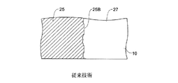
いくつかの場合においては、除去処理の間にドナー要素12の露光領域に対応する一部のドナー材料が、意図されたとおりに基板10に付着せずに、むしろドナー要素12に部分的に付着したまま残ることがある。ドナー要素12に対するドナー材料の部分的な付着は、基板10からドナー要素12を除去することを困難にし得る。いくつかの場合においては、基板10からのドナー要素12の除去が、基板10に転写されたドナー材料の一部と、ドナー要素12に取り付いたまま残るドナー材料の一部の間に不規則な分離を結果としてもたらし得る。たとえば図1Bは、基板10の上面に位置決めされたドナー要素12の部分を示す。ドナー要素12の領域が露光されて作像領域25を形成している。作像領域25は、作像された画像の縁25Aに沿って非作像領域27から分離される。しかしながら基板10からドナー要素12を除去する間に画像縁25Aにおいてきれいに分離されるのではなく、画像縁25Aの近傍の作像領域25内のより大きなゾーン内で分離が生ずることがある。図1Cに示されるとおり、ドナー要素12が除去された後、ドナー材料が、画像縁25Aに対応する基板10の領域に沿って均一に分布したままでは残らないことがある。むしろ、この領域に転写されて残っているドナー材料が望ましい量より少なくなる可能性があり、かつこの領域に沿う転写されたドナー要素の分布が不均一になる可能性がある。これは、破断およびそのほかの多様な不連続を含む縁25Bの形成を導く可能性がある。これらの破断した縁は、結果として最終画像における不快な視覚的アーティファクトをもたらし得る。それに加えて、ドナー材料が非作像領域27の中まで広がることもあり、それもまた望ましくない。   In some cases, some donor material corresponding to the exposed area of donor element 12 during the removal process does not adhere to substrate 10 as intended, but rather partially adheres to donor element 12. May remain. Partial deposition of donor material on donor element 12 can make it difficult to remove donor element 12 from substrate 10. In some cases, removal of donor element 12 from substrate 10 is irregular between the portion of donor material transferred to substrate 10 and the portion of donor material that remains attached to donor element 12. Separation can result. For example, FIG. 1B shows a portion of donor element 12 positioned on the top surface of substrate 10. An area of the donor element 12 is exposed to form an imaging area 25. The image forming area 25 is separated from the non-image forming area 27 along the edge 25A of the image formed. However, rather than cleanly separating at the image edge 25A during removal of the donor element 12 from the substrate 10, separation may occur within a larger zone in the imaging area 25 near the image edge 25A. As shown in FIG. 1C, after the donor element 12 is removed, the donor material may not remain uniformly distributed along the region of the substrate 10 corresponding to the image edge 25A. Rather, there may be less than desired amount of donor material transferred to this region and the distribution of transferred donor elements along this region may be non-uniform. This can lead to the formation of edges 25B including breaks and other various discontinuities. These broken edges can result in unpleasant visual artifacts in the final image. In addition, the donor material may extend into the non-imaged region 27, which is also undesirable.

基板から作像された媒体をより効果的に除去するための方法および装置を提供することへの普遍的な要望がある。   There is a universal desire to provide a method and apparatus for more effectively removing imaged media from a substrate.

ドナー要素から基板へドナー材料が転写された後に基板からドナー要素をより効果的に除去するための方法および装置を提供することへの普遍的な要望がある。   There is a universal desire to provide a method and apparatus for more effectively removing a donor element from a substrate after the donor material has been transferred from the donor element to the substrate.

本発明は、媒体に作像(画像を形成)するための方法に関係する。媒体は、基板および媒体を層状構成で支持する支持体上に置かれる。作像ヘッドが作動され、作像ヘッドと支持体の間に相対的な移動をもたらす間に、作像される媒体の表面に向かって照射ビームを指向することによって媒体に作像する。たとえば遊び(アイドラ)ローラ等のローラを作像された媒体に接触させる。ローラは、作像された媒体の表面の非作像領域に接触させることが可能であり、非作像領域は、作像された媒体の表面の照射ビームによる入射のない領域に対応する。非作像領域は、媒体の縁部分とすることができる。   The present invention relates to a method for forming an image (forming an image) on a medium. The medium is placed on a substrate and a support that supports the medium in a layered configuration. The imaging head is actuated to image the media by directing the illuminating beam toward the surface of the media being imaged while providing relative movement between the imaging head and the support. For example, a roller such as an idler roller is brought into contact with the imaged medium. The roller can be in contact with a non-imaged area on the surface of the imaged medium, the non-imaged area corresponding to an area on the surface of the imaged medium that is not incident by the illumination beam. The non-image area can be the edge portion of the medium.

ローラは、回転軸周りに回転可能である。ローラの回転軸と支持体の間に相対的な移動がもたらされ、作像された媒体の表面の照射ビームによる入射のある領域上において転がり方向に沿うローラの転がりが生じる。ローラは、縁部分から離れる側に導く方向に沿って作像された媒体の表面上を転がすことができる。その後、作像された媒体が基板から除去される。1つの実施態様においては、作像された媒体を基板から剥離する間、ローラの円筒表面の部分の上に作像された媒体の部分を巻き付けることによって作像された媒体を除去することが可能である。剥離方向は、転がり方向と同じ方向または反対方向とすることができる。1つの実施態様においては、必須ではないが、転がり方向を、走査方向、支持体の移送方向、または基板上に形成されるストライプ特徴の方向と平行にすることが可能である。   The roller is rotatable around a rotation axis. Relative movement is provided between the roller axis of rotation and the support, causing the roller to roll along the rolling direction over a region of the imaged medium surface that is incident by the irradiated beam. The roller can roll on the surface of the imaged medium along a direction leading to the side away from the edge portion. Thereafter, the imaged medium is removed from the substrate. In one embodiment, the imaged media can be removed by wrapping the portion of the imaged media over the portion of the cylindrical surface of the roller while peeling the imaged media from the substrate. It is. The peeling direction can be the same direction as the rolling direction or the opposite direction. In one embodiment, although not required, the rolling direction can be parallel to the scanning direction, the transport direction of the support, or the direction of the stripe features formed on the substrate.

基板から作像された媒体が除去された後、追加の媒体を層状構成で支持体上の基板上に置くことができる。この追加の媒体は、作像ヘッドと支持体の間に相対的な移動をもたらす間に作像することが可能である。作像された追加の媒体は、その後、ローラの回転軸と支持体の間に相対的な移動をもたらす間に基板から除去することが可能である。   After the imaged media is removed from the substrate, additional media can be placed on the substrate on the support in a layered configuration. This additional medium can be imaged while providing relative movement between the imaging head and the support. The imaged additional media can then be removed from the substrate while providing relative movement between the axis of rotation of the roller and the support.

1つの実施態様においては巻き取りローラを使用することが可能であり、当該巻き取りローラは、媒体の表面上において転がされない間に、作像された媒体の部分を巻き取る。作像された媒体の部分は、基板から作像された媒体を除去する間に巻き取りローラ上に巻き取ることが可能である。   In one embodiment, a take-up roller can be used, which takes up a portion of the imaged media while it is not rolled on the surface of the media. The portion of the imaged media can be wound on a take-up roller while removing the imaged media from the substrate.

1つの実施態様においては、たとえば磁性粒子ブレーキ等のブレーキまたはそのほかの適切なブレーキが使用されて、作像された媒体の表面の部分の上でローラを転がす間に、ローラに抗力(drag)を選択的に印加する。   In one embodiment, a brake such as a magnetic particle brake or other suitable brake is used to drag the roller while rolling it over a portion of the surface of the imaged media. Apply selectively.

別の実施態様においては、媒体に作像するための方法が、基板および媒体を層状構成で支持するための支持体を用意することを含む。媒体および基板が層状構成にある間に、作像ヘッドが作動され、照射ビームを媒体に向けて放射し、媒体の作像を行う。ローラを作像された媒体の表面に接触させる。たとえば回転性の抗力等の抗力が、作像された媒体の表面上でローラを転がす間にローラに選択的に印加される。この抗力はブレーキを用いて印加するか、またはアクチュエータの作動によって印加することが可能である。作像された媒体が基板から除去される。ローラは、基板からの作像された媒体の剥離に先行して、またはそれと同時に、作像された媒体の表面上において転がすことができる。   In another embodiment, a method for imaging a medium includes providing a substrate and a support for supporting the medium in a layered configuration. While the media and substrate are in a layered configuration, the imaging head is activated to emit an illumination beam toward the media to image the media. A roller is brought into contact with the surface of the imaged media. For example, drag, such as rotational drag, is selectively applied to the roller while it is rolling on the surface of the imaged media. This drag can be applied using a brake or by actuation of an actuator. The imaged medium is removed from the substrate. The roller can be rolled over the surface of the imaged media prior to or simultaneously with the release of the imaged media from the substrate.

1つの実施態様においては、作像された媒体の表面上で複数の異なる方向に沿ってローラを転がすことが可能であり、かつそれぞれの方向に沿って表面上でローラが転がされるとき、異なる量、異なる回数の抗力を選択的にローラに印加することが可能である。ローラは、作像された媒体および基板を層状構成で維持している間に、作像された媒体の表面上において転がすことができる。ローラは、媒体を基板から剥離する間に、作像された媒体の表面上を転がすことができる。接触ローラが作像された媒体の表面上において転がることが可能であり、基板から作像された媒体を剥離する間に、作像された媒体の部分を接触ローラの表面の部分の上に巻き付けることができる。巻き取りローラを使用することが可能であり、当該巻き取りローラは、作像された媒体の表面上において転がされない間に、作像された媒体の部分を巻き取る。作像された媒体の部分は、作像された媒体を基板から剥離する間に巻き取りローラの上に巻くことが可能である。   In one embodiment, the roller can be rolled along a plurality of different directions on the surface of the imaged media, and when the roller is rolled on the surface along each direction, Different amounts and different numbers of drag can be selectively applied to the roller. The roller can roll on the surface of the imaged media while maintaining the imaged media and substrate in a layered configuration. The roller can roll over the surface of the imaged media while peeling the media from the substrate. The contact roller can roll over the surface of the imaged media and wrap the portion of the imaged media over the portion of the surface of the contact roller while peeling the imaged media from the substrate be able to. A take-up roller can be used, which takes up a portion of the imaged media while not being rolled over the surface of the imaged media. The portion of the imaged media can be wound on a take-up roller while peeling the imaged media from the substrate.

別の実施態様においては、基板が支持体上に支持される。支持体上に基板を支持した後に基板上にドナー要素が位置決めされる。作像ヘッドが作動されて、照射ビームをドナー要素に向けて指向することによってドナー要素に作像する。回転軸周りに回転可能なローラを、作像されたドナー要素の表面に接触させる。ローラの回転軸と作像されたドナー要素の間に複数の相対的な移動がもたらされ、作像されたドナー要素の1つまたは複数の作像領域上において複数回にわたってローラの転がりを生じさせる。ローラは、それを1つまたは複数の作像領域上で転がす都度、同一の方向に、または異なる方向に転がすことが可能である。   In another embodiment, the substrate is supported on a support. After supporting the substrate on the support, the donor element is positioned on the substrate. The imaging head is activated to image the donor element by directing the illumination beam toward the donor element. A roller rotatable about the axis of rotation is brought into contact with the surface of the imaged donor element. Multiple relative movements are provided between the roller axis of rotation and the imaged donor element, resulting in multiple roller rolls on one or more imaged areas of the imaged donor element. Let The roller can be rolled in the same direction or in different directions each time it is rolled over one or more imaging areas.

ブレーキまたはそのほかのデバイスを用いて、ローラの回転軸と作像された(画像が形成された)ドナー要素の間における1つの相対的な移動の間に、作像されたドナー要素の1つまたは複数の作像領域上をローラが転がるとき、ローラの回転軸と作像されたドナー要素の間における別の相対的な動きの間とは異なる量の抗力をローラに印加することができる。   Using a brake or other device, during one relative movement between the axis of rotation of the roller and the imaged (imaged) donor element, one of the imaged donor elements or As the roller rolls over multiple imaging regions, a different amount of drag can be applied to the roller than during another relative movement between the roller axis of rotation and the imaged donor element.

ローラの回転軸と作像されたドナー要素の間における相対的な移動の間に、作像されたドナー要素が基板から除去される。基板は、作像されたドナー要素が基板から除去された後に支持体から除去される。基板は、ローラの回転軸と作像されたドナー要素の間における複数の相対的な移動のうちのいずれの相対的な移動の間においても支持体から除去されない。   During the relative movement between the roller axis of rotation and the imaged donor element, the imaged donor element is removed from the substrate. The substrate is removed from the support after the imaged donor element is removed from the substrate. The substrate is not removed from the support during any of the plurality of relative movements between the roller axis of rotation and the imaged donor element.

作像されたドナー要素が基板から除去された後、第2のドナー要素を基板上に位置決めし、作像することができる。第2のドナー要素は、ローラの回転軸と作像された第2のドナー要素の間に相対的な移動をもたらす間に基板から除去することができる。   After the imaged donor element is removed from the substrate, a second donor element can be positioned on the substrate and imaged. The second donor element can be removed from the substrate while providing relative movement between the axis of rotation of the roller and the imaged second donor element.

作像されたドナー要素の領域上でローラを転がすことは、ドナー要素が基板から剥離されるときに、特徴の縁に沿った縁の不連続を低減する。ローラが作像されたドナー要素の領域上において転がされるときにローラに印加される抗力の量を増加させるように構成されたブレーキを使用することによって、作像されたドナー要素が基板から剥離されるときに基板の表面に転写されて残るドナー材料の量が調整される。   Rolling the roller over the area of the imaged donor element reduces edge discontinuities along the edge of the feature as the donor element is peeled from the substrate. By using a brake configured to increase the amount of drag applied to the roller as the roller is rolled over the area of the imaged donor element, the imaged donor element is removed from the substrate. The amount of donor material that remains transferred to the surface of the substrate when peeled is adjusted.

別の実施態様においては、媒体に作像するための、基板および媒体を層状構成で支持するよう構成された支持体を含む装置が提供される。作像ヘッドが、媒体に向けて照射ビームを放射して媒体に作像するよう構成される。ローラが提供され、ブレーキが、ローラに対して抗力を選択的に印加するよう構成されている。シャーシが、当該シャーシに関してローラが回転できるようにローラを支持する。コントローラ(1つであっても複数であってもよい)が、作像ヘッドを作動して媒体に向けて照射ビームを放射させるべく構成される。コントローラは、シャーシと支持体の間に相対的な移動をもたらし、作像された媒体および基板が層状構成となっている間、作像された媒体の近傍にローラを移動させる。またコントローラは、シャーシと支持体の間に複数回の相対的な移動をもたらし、作像された媒体の表面上において複数回にわたりローラの転がりを生じさせる。それに加えてコントローラは、ブレーキをコントロールし、ローラに印加される抗力を、シャーシと支持体の間における1つの相対的な移動と、シャーシと支持体の間における別の相対的な移動と、の間で選択的に変更することが可能である。   In another embodiment, an apparatus is provided that includes a substrate and a support configured to support the medium in a layered configuration for imaging a medium. An imaging head is configured to emit an irradiation beam toward the medium and to image the medium. A roller is provided and the brake is configured to selectively apply a drag to the roller. A chassis supports the rollers such that the rollers can rotate with respect to the chassis. A controller (which may be one or more) is configured to operate the imaging head to emit an illumination beam toward the medium. The controller provides relative movement between the chassis and the support and moves the rollers in the vicinity of the imaged media while the imaged media and substrate are in a layered configuration. The controller also provides multiple relative movements between the chassis and the support, causing the roller to roll multiple times on the surface of the imaged media. In addition, the controller controls the brake and applies the drag applied to the roller between one relative movement between the chassis and the support and another relative movement between the chassis and the support. It is possible to selectively change between.

作像されたドナー要素が基板から剥離される従来技術の熱転写プロセスを示した説明図である。FIG. 3 is an illustration showing a prior art thermal transfer process in which the imaged donor element is peeled from the substrate. 作像されたドナー要素が従来的に基板から剥離されるときの縁の不連続の形成を示した説明図である。FIG. 6 is an illustration showing the formation of edge discontinuities when the imaged donor element is conventionally peeled from the substrate. 作像されたドナー要素が従来的に基板から剥離されるときの縁の不連続の形成を示した説明図である。FIG. 6 is an illustration showing the formation of edge discontinuities when the imaged donor element is conventionally peeled from the substrate. 本発明の一例の実施態様に従った画像形成システムを略図的に示した平面図である。1 is a plan view schematically illustrating an image forming system according to an exemplary embodiment of the present invention. 図2Aの作像システムの略図的な部分断面図である。2B is a schematic partial cross-sectional view of the imaging system of FIG. 2A. FIG. 本発明の一例の実施態様に従って基板から作像されたドナー要素を除去する前に作像されたドナー要素上において接触ローラを転がす態様を略図的に示した説明図である。FIG. 6 schematically illustrates an embodiment of rolling a contact roller over an imaged donor element prior to removing the imaged donor element according to an example embodiment of the present invention. 本発明の一例の実施態様に従って図2Cのドナー要素を除去するシート除去装置によって採用される一連の動作を略図的に示した説明図である。2D is an illustration that schematically illustrates a series of operations employed by the sheet removal apparatus of FIG. 2C for removing the donor element according to an example embodiment of the present invention. 本発明の一例の実施態様に従って図2Cのドナー要素を除去するシート除去装置によって採用される一連の動作を略図的に示した説明図である。2D is an illustration that schematically illustrates a series of operations employed by the sheet removal apparatus of FIG. 2C for removing the donor element according to an example embodiment of the present invention. 本発明の一例の実施態様に従って図2Cのドナー要素を除去するシート除去装置によって採用される一連の動作を略図的に示した説明図である。2D is an illustration that schematically illustrates a series of operations employed by the sheet removal apparatus of FIG. 2C for removing the donor element according to an example embodiment of the present invention. 本発明の一例の実施態様に従った方法を表すフローチャートである。6 is a flowchart representing a method according to an example embodiment of the present invention. 基板によって支持される作像されたドナー要素上を転がるときの接触ローラの動きを表す略図的な力線図である。FIG. 6 is a schematic force diagram representing the movement of a contact roller as it rolls over an imaged donor element supported by a substrate.

以下の説明全体を通じて、より完全な理解を当業者に提供するべく特定の詳細が示されている。しかしながら周知の要素は、不必要に開示を不明瞭化することを回避するべく、詳細に示されないか、または説明されないことがある。したがって説明および図面は、限定の意味ではなく例示として考えるものとする。それに加えて、図面は必ずしも共通の縮尺を有するものでなく、それの部分が明瞭性のために誇張されることもある。   Throughout the following description, specific details are given to provide a more thorough understanding to those skilled in the art. However, well-known elements may not be shown or described in detail to avoid unnecessarily obscuring the disclosure. The description and drawings are accordingly to be regarded in an illustrative rather than a restrictive sense. In addition, the drawings do not necessarily have a common scale, and portions thereof may be exaggerated for clarity.

図3は、本発明の一例の実施態様に従って基板上に支持された作像された媒体を除去するための方法を表すフローチャートを示している。図3に例示されている多様なステップは、本発明の一例の実施態様に従って図2A〜2Fに一部が示された装置100を参照して説明がなされる。これは例示の目的だけのためであり、そのほかの適切な画像形成装置を本発明とともに使用することが可能である。ステップ300においては、媒体が処理されて画像が形成される。この例の実施態様においては、作像技術(すなわち、露光技術としても知られる)によって画像が形成される。作像技術は、表面上への画像の形成に照射ビーム(たとえばレーザ・ビーム)を採用することができる。これらの画像は、多様な方法で形成可能である。たとえば、画像により変更可能な層(image modifiable layer)の性質または特性を変更する作像技術を使用してその層上に画像を形成することができる。表面を融除する作像技術を使用してその表面上に画像を形成することができる。表面へのドナー材料の転写を促進する作像技術を使用してその上に画像を形成することができる。   FIG. 3 shows a flowchart representing a method for removing an imaged medium supported on a substrate in accordance with an example embodiment of the present invention. The various steps illustrated in FIG. 3 are described with reference to the apparatus 100 shown in part in FIGS. 2A-2F in accordance with an example embodiment of the present invention. This is for illustrative purposes only, and other suitable image forming devices can be used with the present invention. In step 300, the media is processed to form an image. In this example embodiment, the image is formed by an imaging technique (ie, also known as an exposure technique). Imaging techniques can employ an irradiation beam (eg, a laser beam) to form an image on the surface. These images can be formed by various methods. For example, an image can be formed on that layer using an imaging technique that modifies the nature or characteristics of the image modifiable layer. An image can be formed on the surface using imaging techniques that ablate the surface. Images can be formed thereon using imaging techniques that facilitate the transfer of donor material to the surface.

この例示された実施態様においては、例としてだけであるが、熱転写プロセスが採用され、媒体がドナー要素112を含む。レーザ等の照射源(図示せず)を含む作像ヘッド102が、ドナー要素112から基板110の表面へのドナー材料(同じく図示せず)の転写のために提供される(図2Aに破線で示されている)。作像ヘッド102は、1つまたは複数のチャンネル114を含むことが可能である。この例示された実施態様においては、作像ヘッド102がチャンネル114の配列を含み、チャンネル114のそれぞれは、個別にコントロールされて照射ビーム116(図2Aには図示せず)を放射することができる。作像ヘッド102が作動され、照射ビーム116を指向してドナー要素112の多様な領域上に入射させる。作像電子回路103が、コントローラ108によって提供される画像データ104に従ってチャンネル102からの照射ビーム116の放射をコントロールする。   In this illustrated embodiment, by way of example only, a thermal transfer process is employed and the media includes donor element 112. An imaging head 102 including an irradiation source (not shown) such as a laser is provided for the transfer of donor material (also not shown) from the donor element 112 to the surface of the substrate 110 (shown in broken lines in FIG. 2A). It is shown). The imaging head 102 can include one or more channels 114. In this illustrated embodiment, the imaging head 102 includes an array of channels 114, each of which can be individually controlled to emit an illumination beam 116 (not shown in FIG. 2A). . The imaging head 102 is activated and directs the illumination beam 116 to be incident on various regions of the donor element 112. Imaging electronics 103 controls the emission of illumination beam 116 from channel 102 in accordance with image data 104 provided by controller 108.

この例示された実施態様においては、画像データ104に応答してチャンネル114がコントロールされて像様態様で照射ビーム116をドナー要素112の上で走査する間に、基板110、作像ヘッド102、またはこれら両方の組み合わせが互いに対して移動される。いくつかの場合においては、作像ヘッド102が静止であり、基板110が移動される。ほかの場合においては、基板110が静止であり、作像ヘッド102が移動される。さらにほかの場合においては、作像ヘッド102および基板110両方が移動される。本発明のいくつかの例の実施態様においては、作像ヘッド102がステップ・アンド・リピート方式でドナー112を露光する。それらの実施態様においては、露光と露光の間に作像ヘッド102とドナー要素112の間の相対的な移動が生じてもよい。いくつかの場合においてはドナー要素112が、単一の露光または走査で作像するには大きすぎることがある。画像の完成に作像ヘッド102の複数の露光または走査が要求されることがある。   In this illustrated embodiment, the channel 110 is controlled in response to the image data 104 to scan the illumination beam 116 over the donor element 112 in an imagewise manner, while the substrate 110, the imaging head 102, or Both combinations are moved relative to each other. In some cases, the imaging head 102 is stationary and the substrate 110 is moved. In other cases, the substrate 110 is stationary and the imaging head 102 is moved. In still other cases, both the imaging head 102 and the substrate 110 are moved. In some example embodiments of the invention, imaging head 102 exposes donor 112 in a step-and-repeat manner. In those embodiments, relative movement between imaging head 102 and donor element 112 may occur between exposures. In some cases, donor element 112 may be too large to image with a single exposure or scan. Multiple exposures or scans of the imaging head 102 may be required to complete the image.

任意の適切なメカニズムを適用して作像ヘッド102を基板110に対して移動することができる。実質的に平坦な表面上への画像の形成のためには、通常はフラットベッド・マーキング・システムが使用される。ゲルバート(Gelbart)に対する米国特許第6,957,773号には、表示パネルの露光に適した高速フラットベッド作像機が説明されている。いくつかの例の実施態様においては、適切に柔軟な基板を「ドラム型」支持体の外側または内側表面のいずれかに固定し、表示アセンブリ(複数の部品が組み立てられることで構成されたもの)上の画像の形成に影響を及ぼすことが可能である。   Any suitable mechanism can be applied to move the imaging head 102 relative to the substrate 110. For the formation of an image on a substantially flat surface, a flatbed marking system is usually used. US Pat. No. 6,957,773 to Gelbert describes a high speed flatbed imager suitable for display panel exposure. In some example embodiments, a suitably flexible substrate is secured to either the outer or inner surface of a “drum-type” support and a display assembly (configured by assembling multiple parts) It is possible to influence the formation of the above image.

図2Aは、装置100の画像形成システムの略図的な平面図を示す。図2Aにおいては、基板110およびドナー要素112を層状構成で支持するために支持体101が提供される。この例示された実施態様においては、支持体101が、主走査軸42に整列する経路に沿って基板110およびドナー要素112を移送するように構成されている。この実施態様においては、支持体101が複数の移送方向(すなわち順方向42Aおよび逆方向42B)に沿って移動できる。順方向42Aは、逆方向42Bの反対である。支持体101は、順方向42Aと逆方向42Bの間を往復運動することができる。作像ヘッド102は、支持体101を跨ぐ支持体105の上で移動可能に支持される。この例の実施態様においては、作像ヘッド102が副走査軸44に整列する経路に沿って移動可能である。この実施態様においては作像ヘッド102が、離れる方向44Aに沿って移動すること、及び復帰方向44Bに沿って移動することが可能である。離れる方向44Aは復帰方向44Bの反対である。この例示された実施態様においては、作像ヘッド102がドナー要素112の上で照射ビーム116を双方向に走査して画像を形成することができる。双方向走査技術は、反対の走査方向のそれぞれにおいて走査を行うことが可能であるため、作像の生産性を向上させることが可能である。   FIG. 2A shows a schematic plan view of the image forming system of the apparatus 100. In FIG. 2A, a support 101 is provided to support the substrate 110 and donor element 112 in a layered configuration. In this illustrated embodiment, support 101 is configured to transport substrate 110 and donor element 112 along a path that is aligned with main scan axis 42. In this embodiment, the support 101 can move along a plurality of transport directions (ie, forward direction 42A and reverse direction 42B). The forward direction 42A is opposite to the reverse direction 42B. The support 101 can reciprocate between the forward direction 42A and the reverse direction 42B. The image forming head 102 is movably supported on a support 105 that straddles the support 101. In this example embodiment, the imaging head 102 is movable along a path that is aligned with the sub-scanning axis 44. In this embodiment, the imaging head 102 can move along the leaving direction 44A and move along the return direction 44B. The away direction 44A is opposite to the return direction 44B. In this illustrated embodiment, the imaging head 102 can scan the illumination beam 116 bidirectionally over the donor element 112 to form an image. Since the bidirectional scanning technique can perform scanning in each of the opposite scanning directions, it is possible to improve image forming productivity.

移動システム109が、支持体101および/または作像ヘッド102の移動を生じさせるべく提供され、適切な駆動装置、伝動部材、および/または案内部材を含むことができる。移動システム109は、1つまたは複数の移動システムを含むことができる。当業者は理解するであろうが、別々の移動システムを使用して装置100内の異なるシステムを作動することも可能である。   A movement system 109 is provided to cause movement of the support 101 and / or the imaging head 102 and can include suitable drive devices, transmission members, and / or guide members. The mobile system 109 can include one or more mobile systems. As those skilled in the art will appreciate, it is also possible to operate different systems within apparatus 100 using separate mobile systems.

1つまたは複数のコントローラを含むことが可能なコントローラ108は、移動システム109を含む装置100の1つまたは複数のシステムのコントロールに使用される(ただし、これに限定されるものではない)。コントローラ108は、作像ヘッド102に対して画像データ104が転送されるようにすること、および作像ヘッドをコントロールし、このデータに従って照射ビーム116放射させること、ができる。またコントローラ108は、装置100以外のシステムをコントロールすることもできる。コントローラ108は、適切なソフトウエアを実行するべく構成でき、非限定的な例としてアクセス可能メモリ、論理回路、ドライバ、増幅器、A/DおよびD/Aコンバータ、入力/出力ポート、およびこれらの類を含む適切なハードウエアとともに1つまたは複数のデータ・プロセッサを含むことができる。コントローラ108は、例えば、マイクロプロセッサ、1チップ・コンピュータ、コンピュータのCPU、またはそのほかの任意の適切なマイクロコントローラなどである(ただし、これらに限定されるものではない)。コントローラ108は、マテリアルハンドリングシステムとの関連付けが可能である。   A controller 108, which can include one or more controllers, is used to control (but is not limited to) one or more systems of the device 100 that includes the mobile system 109. The controller 108 can cause the image data 104 to be transferred to the imaging head 102 and can control the imaging head to emit the illumination beam 116 in accordance with this data. The controller 108 can also control a system other than the device 100. The controller 108 can be configured to execute appropriate software, and as non-limiting examples, accessible memory, logic circuits, drivers, amplifiers, A / D and D / A converters, input / output ports, and the like. One or more data processors can be included with suitable hardware including: The controller 108 is, for example, a microprocessor, a one-chip computer, a computer CPU, or any other suitable microcontroller, but is not limited thereto. The controller 108 can be associated with a material handling system.

図2Bは、装置100の画像形成システムの模式的な部分断面図を示す。例示された熱転写プロセスにおいては、この分野で周知の多様な技術(たとえば吸引)によって支持体101に基板110を固定できる。この例示された実施態様においては、ドナー要素112が基板110との層状構成で配置され、この構成においてはドナー要素112は、支持体101上に基板110が支持された後に基板110の上に置かれる。画像品質を保持するために、作像の間にわたり、基板110に関してドナー要素112の移動が防止されることが望ましい。図2Bに示されているとおり、支持体101は、基板110の縁から横方向に間隔があけられ、かつ基板110の厚さと実質的に類似の高さを有するスタンド118を含む。また支持体101は、スタンド118と基板110の間の空間122に吸引力を印加する1つまたは複数の吸引機構120も含む。この吸引力がドナー要素112を基板110に固定する。当業者によって認識されることになろうが、このほかにもドナー要素112を基板110に固定するための追加の、および/または代替の技術があり、本発明には、その種の追加の、および/または代替のドナー要素固定技術が利用可能であることが理解されるであろう。   FIG. 2B shows a schematic partial cross-sectional view of the image forming system of the apparatus 100. In the illustrated thermal transfer process, the substrate 110 can be secured to the support 101 by a variety of techniques well known in the art (eg, suction). In this illustrated embodiment, the donor element 112 is arranged in a layered configuration with the substrate 110, in which the donor element 112 is placed on the substrate 110 after the substrate 110 is supported on the support 101. It is burned. In order to preserve image quality, it is desirable to prevent movement of the donor element 112 relative to the substrate 110 during imaging. As shown in FIG. 2B, the support 101 includes a stand 118 that is laterally spaced from the edge of the substrate 110 and has a height substantially similar to the thickness of the substrate 110. The support 101 also includes one or more suction mechanisms 120 that apply a suction force to the space 122 between the stand 118 and the substrate 110. This suction force secures the donor element 112 to the substrate 110. As will be appreciated by those skilled in the art, there are additional and / or alternative techniques for securing the donor element 112 to the substrate 110, and the present invention includes such additional, It will be appreciated that and / or alternative donor element immobilization techniques can be utilized.

ドナー要素112から基板110へのドナー材料の転写は、たとえば多様なレーザ誘起熱転写技術を使用して実装できる。本発明によって使用されるレーザ誘起熱転写プロセスの例は、レーザ誘起「染料転写」プロセス、レーザ誘起「溶解転写」プロセス、レーザ誘起「アブレーション転写」プロセス、およびレーザ誘起「マス転写」プロセスを含む。   Transfer of donor material from donor element 112 to substrate 110 can be implemented using a variety of laser-induced thermal transfer techniques, for example. Examples of laser induced thermal transfer processes used by the present invention include laser induced “dye transfer” processes, laser induced “melt transfer” processes, laser induced “ablation transfer” processes, and laser induced “mass transfer” processes.

概して基板110、ドナー要素112、およびドナー材料の構成は、特定の作像応用に依存する。特定の実施態様においては、作像装置100が、基板110上における表示器用のカラー・フィルタの製造に使用される。その種の実施態様においては、基板110が一般に透明材料(たとえばガラス)から作られ、ドナー要素112が一般にプラスティックから作られ、ドナー材料が1つまたは複数の色材を含む。その種の色材は、たとえば適切な染料ベースまたは顔料ベースの組成を含むことができる。またドナー材料は、1つまたは複数の適切なバインダ材料も包含できる。   In general, the configuration of substrate 110, donor element 112, and donor material will depend on the particular imaging application. In a particular embodiment, the imaging device 100 is used to manufacture a color filter for a display on the substrate 110. In such an embodiment, the substrate 110 is generally made of a transparent material (eg, glass), the donor element 112 is generally made of plastic, and the donor material includes one or more colorants. Such colorants can include, for example, suitable dye-based or pigment-based compositions. The donor material can also include one or more suitable binder materials.

例示された実施態様においては、照射ビーム116がドナー要素112の作像領域112Bの多様なエリアに入射するようにそれらを放射するべく作像ヘッド102が強制される。その結果としてドナー要素112の領域112Aが非作像エリアとして残り、いくつかの場合においては、作像領域112Bの周囲の境界を提供することができる。したがって、例示された実施態様においては、ドナー材料がドナー要素112から基板110の作像領域110B上だけに転写され、基板110の非作像領域110A上には転写されない。例示された実施態様においては、非作像領域112Aの部分113が基板110を越えて被さり、スタンド118によって支持される。   In the illustrated embodiment, the imaging head 102 is forced to irradiate the illumination beam 116 such that it is incident on various areas of the imaging region 112B of the donor element 112. As a result, the region 112A of the donor element 112 remains as a non-imaged area, and in some cases can provide a border around the imaged region 112B. Thus, in the illustrated embodiment, the donor material is transferred from the donor element 112 only onto the imaging area 110B of the substrate 110 and not onto the non-imaging area 110A of the substrate 110. In the illustrated embodiment, a portion 113 of the non-imaged area 112A covers over the substrate 110 and is supported by a stand 118.

作像プロセスの終わりにドナー要素112が基板110から除去される。この例の実施態様においては、基板110上に形成された多様な特徴の縁における破断その他の不連続の存在を低減する態様で、基板110からドナー要素112が除去されることが望まれる。   At the end of the imaging process, the donor element 112 is removed from the substrate 110. In this example embodiment, it is desirable that donor element 112 be removed from substrate 110 in a manner that reduces the presence of breaks and other discontinuities at the edges of the various features formed on substrate 110.

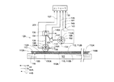
図2Cは、支持体101、基板110、および作像されたドナー要素112の一端を図示した模式的な部分側面図である。基板110からの作像されたドナー要素112の除去は、この例示された実施態様において装置100の部分を形成するシート除去装置129によってもたらされる。例示された実施態様においては、シート除去装置129がシャーシ136および、対応するローラ連結器のペア(接触ローラ連結器138および巻き取りローラ連結器140)によってシャーシ136と機械的に結合される複数のローラ(すなわち、接触ローラ130および巻き取りローラ132)を含む。   FIG. 2C is a schematic partial side view illustrating one end of the support 101, the substrate 110, and the imaged donor element 112. Removal of the imaged donor element 112 from the substrate 110 is provided by a sheet removal device 129 that forms part of the device 100 in this illustrated embodiment. In the illustrated embodiment, a plurality of sheet removal devices 129 are mechanically coupled to the chassis 136 by the chassis 136 and corresponding pairs of roller couplers (contact roller coupler 138 and take-up roller coupler 140). Rollers (ie, contact roller 130 and take-up roller 132).

ローラ130、132は、好ましくは形状において実質的に円筒状とする。接触ローラ連結器138および巻き取りローラ連結器140は、それぞれのローラ130、132の、それらの対応する回転軸130A、132A周りの回転を可能にする。例示された実施態様においては、巻き取りローラ連結器140が、シャーシ136に関する巻き取りローラ132の軸132Aの移動をもたらすアクチュエータ133を含む。アクチュエータ133は、ここでは「巻き取りローラ軸位置アクチュエータ133」と呼ばれる。巻き取りローラ軸位置アクチュエータ133は、コントローラ108により信号135を使用してコントロール(制御)できる。巻き取りローラ軸位置アクチュエータ133は、概して任意の適切に結合されるアクチュエータを包含できる。巻き取りローラ軸位置アクチュエータ133の提供に使用できるアクチュエータの例(但しこの例に限定されるものではない)は、適切に結合される電気モータおよび/または空気圧アクチュエータを含む。   The rollers 130, 132 are preferably substantially cylindrical in shape. Contact roller coupler 138 and take-up roller coupler 140 allow respective rollers 130, 132 to rotate about their corresponding axes of rotation 130A, 132A. In the illustrated embodiment, the take-up roller coupler 140 includes an actuator 133 that provides movement of the shaft 132 A of the take-up roller 132 relative to the chassis 136. The actuator 133 is referred to herein as a “winding roller shaft position actuator 133”. The take-up roller shaft position actuator 133 can be controlled by the controller 108 using the signal 135. The take-up roller shaft position actuator 133 can generally include any suitably coupled actuator. Examples of actuators that can be used to provide the take-up roller shaft position actuator 133 include, but are not limited to, electric motors and / or pneumatic actuators that are suitably coupled.

例示された実施態様においては、巻き取りローラ連結器140が、軸132A周りに巻き取りローラ132の回転を生じさせる巻き取りローラ回転アクチュエータ139も含む。巻き取りローラ回転アクチュエータ139は、コントローラ108により信号141を使用してコントロールできる。好ましくは巻き取りローラ回転アクチュエータ139が、適切に結合されるモータを含むが、巻き取りローラ回転アクチュエータ139は、概して任意の適切に構成されるアクチュエータを包含できる。   In the illustrated embodiment, the take-up roller coupler 140 also includes a take-up roller rotation actuator 139 that causes the take-up roller 132 to rotate about the axis 132A. The take-up roller rotary actuator 139 can be controlled by the controller 108 using the signal 141. Preferably, the take-up roller rotary actuator 139 includes a suitably coupled motor, but the take-up roller rotary actuator 139 can generally include any suitably configured actuator.

例示された実施態様においては巻き取りローラ132が1つまたは複数の吸引機構134も含む。吸引機構134は、吸引源143と流体が流れるように結合されるオリフィスを包含できる。この分野で周知のとおり、吸引源143は、適切に構成されたポンプまたはその類といった正または負の圧力差を作り出すためのメカニズムを包含できる。吸引源143は、コントローラ108により信号145を使用してコントロールされ、またそれは吸引源143による吸引力の印加に関係する1つまたは複数のバルブまたは類似の構成要素(図示せず)もコントロールできる。   In the illustrated embodiment, the take-up roller 132 also includes one or more suction mechanisms 134. The suction mechanism 134 may include an orifice that is coupled to a suction source 143 for fluid flow. As is well known in the art, the suction source 143 can include a mechanism for creating a positive or negative pressure differential, such as a suitably configured pump or the like. The suction source 143 is controlled by the controller 108 using the signal 145, which can also control one or more valves or similar components (not shown) related to the application of suction force by the suction source 143.

例示された実施態様においては、接触ローラ130が、非駆動「遊び(アイドラ)」ローラである。別の実施態様においては、接触ローラ130を回転駆動することができる。またシート除去装置129は、支持体101とシャーシ136の間に相対的な移動を生じさせる1つまたは複数のシャーシ位置アクチュエータ131も含む。支持体101とシャーシ136の間の相対的な移動は、結果として支持体101とローラ130および132の間における対応する移動をもたらす。例示された実施態様においては、シャーシ位置アクチュエータ131が支持体101に対するシャーシ136の移動を生じさせ、支持体101とシャーシ136の間の相対的な移動をもたらす。ほかの実施態様においては、シャーシ位置アクチュエータ131がシャーシ136に関する支持体101の移動を生じさせ、支持体101とシャーシ136の間の相対的な移動をもたらす。シャーシ位置アクチュエータ131は、概して任意の1つまたは複数の適切に結合されるアクチュエータを包含できる。シャーシ位置アクチュエータ131の提供に使用できるアクチュエータの例(但しこの例に限定されるものではない)は、適切に結合される電気モータおよび/または空気圧アクチュエータを含む。   In the illustrated embodiment, the contact roller 130 is a non-driven “idler” roller. In another embodiment, the contact roller 130 can be driven to rotate. Sheet removal apparatus 129 also includes one or more chassis position actuators 131 that cause relative movement between support 101 and chassis 136. The relative movement between the support 101 and the chassis 136 results in a corresponding movement between the support 101 and the rollers 130 and 132. In the illustrated embodiment, the chassis position actuator 131 causes the movement of the chassis 136 relative to the support 101 and provides a relative movement between the support 101 and the chassis 136. In other embodiments, the chassis position actuator 131 causes movement of the support 101 with respect to the chassis 136 and provides relative movement between the support 101 and the chassis 136. Chassis position actuator 131 can generally include any one or more appropriately coupled actuators. Examples of actuators that can be used to provide chassis position actuator 131 include, but are not limited to, electric motors and / or pneumatic actuators that are suitably coupled.

基板110から作像されたドナー要素112の除去が望まれるとき、シャーシ136と、シート除去装置129の残りの部分と、がドナー要素112の1つの縁部分115Aの近傍に位置決めされるように(図2C参照)、コントローラ108が信号を使用してシャーシ位置アクチュエータ131にシャーシ136と支持体101の間の相対的な移動を行わせる。例示された実施態様においては、シート除去装置129が、垂直方向からドナー要素112に近づく。ほかの実施態様においてはシャーシ位置アクチュエータ131が、ほかの方向からシート除去装置129をドナー要素112に近づける(またはドナー要素112をシート除去装置129に近づける)。ステップ310においては、シート除去装置129がドナー要素112に向かって、接触ローラ130がドナー要素112と接触するまで移動する。好ましくは接触ローラ130が、非作像領域112A内において(すなわち作像領域112Bの外側で)ドナー要素112と接触する。接触ローラ130とドナー・シート112の間におけるこの接触の位置決めは、本発明にとって本質的ではないが、ドナー要素112の作像領域112B内における接触ローラ130の衝撃を回避し、その種の衝撃の結果としてもたらされる可能性のある基板110の対応する作像領域110B内の画像の対応する劣化を防止する。例示された実施態様においては巻き取りローラ132にドナー要素112との接触がもたらされていない。この例においては、巻き取りローラ軸位置アクチュエータ133がコントロールされて、巻き取りローラ132をドナー要素112に接触させない。   When removal of the imaged donor element 112 from the substrate 110 is desired, the chassis 136 and the remaining portion of the sheet removal device 129 are positioned in the vicinity of one edge portion 115A of the donor element 112 (see FIG. 2C), the controller 108 uses the signal to cause the chassis position actuator 131 to perform relative movement between the chassis 136 and the support 101. In the illustrated embodiment, the sheet removal device 129 approaches the donor element 112 from the vertical direction. In other embodiments, the chassis position actuator 131 moves the sheet removal device 129 closer to the donor element 112 from other directions (or moves the donor element 112 closer to the sheet removal device 129). In step 310, the sheet removal device 129 moves toward the donor element 112 until the contact roller 130 contacts the donor element 112. Preferably, contact roller 130 contacts donor element 112 within non-imaged region 112A (ie, outside imaged region 112B). The positioning of this contact between the contact roller 130 and the donor sheet 112 is not essential to the present invention, but avoids the impact of the contact roller 130 in the imaging area 112B of the donor element 112 and avoids such impact. Preventing corresponding degradation of the image in the corresponding imaging area 110B of the substrate 110 that may result. In the illustrated embodiment, the take-up roller 132 is not brought into contact with the donor element 112. In this example, the take-up roller shaft position actuator 133 is controlled so that the take-up roller 132 does not contact the donor element 112.

ステップ320においては、接触ローラ130が、作像されたドナー要素112の部分の表面上で転がされる。この例の実施態様では、接触ローラ130が、作像領域112Bを含む作像されたドナー要素112の部分の上において転がされる。本発明のこの例示された実施態様では、ステップ300の間に照射ビームによる入射のあったドナー要素112の領域の上において接触ローラ130が転がされる。この例の実施態様においては、縁部分115Aの近傍の非作像領域112Aから作像領域112Bを越えて縁部分115Bの近傍の非作像領域112Aまで延びる経路に沿って接触ローラ130が転がされる。コントローラ108は、信号137を使用してシャーシ位置アクチュエータ131に、転がり方向(矢印148Aによって示されるとおり)に沿ってシャーシ136(ローラ130、132を含む)を移動させ、支持されたドナー要素112の上において接触ローラ130の転がりを生じさせる。この例示された実施態様では、接触ローラ130が作像されたドナー要素112上において転がされるとき、接触ローラ130が回転する(矢印144によって示されるとおり)。図2Cに示されるとおり、これは矢印148Aの方向に沿って接触ローラ130の回転軸130Aを移動させる。図2Cは、作像されたドナー要素112および基板110が層状構成で位置決めされたままとどまる間に作像されたドナー要素112上において接触ローラ130が転がされる態様を示している。   In step 320, contact roller 130 is rolled over the surface of the portion of donor element 112 that has been imaged. In this example embodiment, contact roller 130 is rolled over the portion of imaged donor element 112 that includes imaging region 112B. In this illustrated embodiment of the invention, the contact roller 130 is rolled over the region of the donor element 112 that was incident by the irradiation beam during step 300. In this example embodiment, the contact roller 130 rolls along a path extending from the non-image area 112A near the edge portion 115A to the non-image area 112A near the edge portion 115B beyond the image formation area 112B. Is done. The controller 108 uses the signal 137 to move the chassis 136 (including rollers 130, 132) along the rolling direction (as indicated by arrow 148 A) to the chassis position actuator 131 and the supported donor element 112. The rolling of the contact roller 130 is generated above. In this illustrated embodiment, as the contact roller 130 is rolled over the imaged donor element 112, the contact roller 130 rotates (as indicated by arrow 144). As shown in FIG. 2C, this moves the rotating shaft 130A of the contact roller 130 along the direction of arrow 148A. FIG. 2C illustrates the manner in which the contact roller 130 is rolled over the imaged donor element 112 while the imaged donor element 112 and substrate 110 remain positioned in a layered configuration.

発明者らは、作像されたドナー要素112上で接触ローラ130等のローラを転がすことが、驚くべきことに、その後に続いて基板110から作像されたドナー要素112を除去するときに縁の不連続等のアーティファクトの存在の低減に使用可能であることを突き止めた。特に発明者らは、基板110からの除去に先行して、作像されたドナー要素112にローラを掛けることにより、特にドナー要素112が基板110から剥離される場合における、作像された特徴の縁におけるドナー材料の破断を低減することが可能となることを発見した。発明者らはいずれかの特定の理論に結びつけられることを欲していないが、形成された画像の視覚的特性を向上させるための1つの可能性のある要因は、接触ローラ130が作像されたドナー要素112上において転がされるとき、作像されたドナー要素112と基板110の間に「微小滑り」が存在することから生じると見られる。しかしながらここで理解されるものとするが、追加のまたは代替の要因が、本発明によって提供されるところの改善された画像特性を導くこともあり得る。   The inventors surprisingly rolled a roller, such as contact roller 130, on the imaged donor element 112, which is subsequently followed when removing the imaged donor element 112 from the substrate 110. It was found that it can be used to reduce the presence of artifacts such as discontinuities. In particular, we have imaged features, particularly when donor element 112 is peeled from substrate 110, by rolling the imaged donor element 112 prior to removal from substrate 110. It has been found that it is possible to reduce the breakage of the donor material at the edges. Although the inventors do not want to be tied to any particular theory, one possible factor for improving the visual characteristics of the formed image was that the contact roller 130 was imaged. When rolled on the donor element 112, it appears to result from the presence of “microslip” between the imaged donor element 112 and the substrate 110. However, it is to be understood that additional or alternative factors may lead to improved image characteristics provided by the present invention.

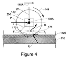
図4は、支持されたドナー要素112上を転がるときの接触ローラ130の動きを表す略図的な力線図を例示する。境界面の力Fを除き、すべての力およびモーメントが接触ローラ130上に作用していることが示されている。接触ローラ130上に作用する力は、接触ローラ130上に作用する荷重Wを含む。荷重Wには、シャーシ位置アクチュエータ131によって接触ローラ130上に掛けられる力を含めてもよい。力Pは、支持されたドナー要素112の表面上を矢印148Aの方向に沿って接触ローラを移動するために必要とされる力を表し、この例示された実施態様においては、シャーシ位置アクチュエータ131によって提供される。偶力Mは、接触ローラ上に作用する摩擦による抵抗または抗力を表し、矢印144の回転方向の反対向きである。この抗力は、例えば、接触ローラ連結器138(図4には図示せず)のベアリングの摩擦抵抗を含む多様な要因によって作り出される。接触ローラ130は、ローラ130と支持されたドナー要素112の間の接触点に多様な変形を導くことが可能な順応性表面を含むことができる。その種の変形が図4のエリア170に示されている。これらの変形は、接触ローラ130とドナー要素112の間の接触を、単一の接触ラインではなく、むしろある特定の面積にわたって生じさせ、それが「転がり抵抗」を増加させることができる。図4に示されている変形は接触ローラ130に限られているが、ローラが転がる表面上においても変形を生じ得ることは理解されるであろう。図4は、支持されたドナー要素112によってこのエリアにわたって接触ローラ130上に印加される力の合力が、点171に印加される反力Rであることを示す。点171は、回転軸130Aの直下ではなく、わずかにそれの前方に位置する。点171は、距離bだけ回転中心172から変位している。距離bは、転がり抵抗係数としてこの分野では知られる。しかしながら、bは長さの単位で表現されることから、無次元の係数ではないことに注意されたい。反力Rの1つの成分が、接触ローラ130と支持されたドナー要素112の間の摩擦力fである。また、ドナー要素112と基板110の間には境界面の力Fも存在する。接触ローラ130の半径は「r」として示されている。 FIG. 4 illustrates a schematic force diagram representing the movement of the contact roller 130 as it rolls over the supported donor element 112. It is shown that all forces and moments are acting on the contact roller 130 except for the interface force F. The force acting on the contact roller 130 includes a load W acting on the contact roller 130. The load W may include a force applied on the contact roller 130 by the chassis position actuator 131. The force P represents the force required to move the contact roller over the surface of the supported donor element 112 along the direction of arrow 148A, and in this illustrated embodiment, by the chassis position actuator 131. Provided. The couple M represents a resistance or drag due to friction acting on the contact roller, and is opposite to the rotation direction of the arrow 144. This drag can be created by a variety of factors including, for example, the frictional resistance of the bearing of the contact roller coupler 138 (not shown in FIG. 4). Contact roller 130 may include a compliant surface capable of directing various deformations to contact points between roller 130 and supported donor element 112. Such a variation is shown in area 170 of FIG. These variations can cause contact between the contact roller 130 and the donor element 112 over a certain area rather than a single contact line, which can increase “rolling resistance”. Although the deformation shown in FIG. 4 is limited to the contact roller 130, it will be understood that the deformation can also occur on the surface on which the roller rolls. FIG. 4 shows that the resultant force applied on the contact roller 130 over this area by the supported donor element 112 is the reaction force R applied to the point 171. The point 171 is not directly under the rotating shaft 130A but slightly in front of it. Point 171 is displaced from center of rotation 172 by a distance b. The distance b is known in this field as the rolling resistance coefficient. However, note that b is not a dimensionless coefficient because it is expressed in units of length. One component of the reaction force R is the frictional force f 1 between the contact roller 130 and the supported donor element 112. There is also a boundary force F between the donor element 112 and the substrate 110. The radius of the contact roller 130 is shown as “r”.

点171に関して接触ローラ130上に作用するモーメントの和は、次の関係式によって表すことができる(すなわち、ローラが一定速度を伴って移動していることを仮定)。
P×r≒M+(W×b) (1)
The sum of the moments acting on the contact roller 130 with respect to the point 171 can be expressed by the following relationship (ie, assuming that the roller is moving with a constant speed):
P × r≈M + (W × b) (1)

接触ローラ130の移動方向148Aに沿って接触ローラ130上に作用する力の和は、次の関係式によって表すことができる(すなわち、ローラが一定速度を伴って移動していることを仮定)。
=P (2)
The sum of forces acting on the contact roller 130 along the moving direction 148A of the contact roller 130 can be expressed by the following relational expression (that is, assuming that the roller is moving with a constant speed).
f 1 = P (2)

関係式(1)および(2)を整理することによって、次の関係式が求められる。
=P≒(M+(W×b))/r (3)
By arranging the relational expressions (1) and (2), the following relational expression is obtained.
f 1 = P≈ (M + (W × b)) / r (3)

これらの多様なパラメータが組み合わさり摩擦力fを境界面の力Fより大きくする場合に、ドナー要素112と基板110の間に何らかの滑りが生じることがある。微小滑りと呼ばれるわずかな量の滑りが、接触エリアの近傍のドナー要素と基板の境界面の領域内に生じることがある。境界面の力Fは多様な要因に依存し、それには作像されたドナー要素112と基板110の間の押圧力(たとえば、ドナー要素112と基板110の間に印加される吸引力)、荷重W、およびドナー要素と基板の境界面に関係する多様な摩擦パラメータを含めることができる。そのほかの要因に剪断力を含めることが可能であり、形成された多様な画像特徴の境界においてドナー材料を剪断するためにはそれに打ち勝たなければならない。摩擦力fが充分に大きく境界面の力Fに打ち勝つ場合には、作像された特徴の境界近傍において、摩擦力fが、作像されたドナー要素112の局在的な剪断を生じさせることから、作像された特徴の境界のドナー材料が剪断され得る。そして、ドナー材料の局在的な剪断は、作像されたドナー要素112が基板110から剥離されるときに、作像された特徴の境界において生じ得る破断の量を低減できる。発明者らは、作像領域112Aを横切って接触ローラ130を転がすと、基板110から作像されたドナー要素112を除去するときに基板110の作像領域110B内に形成された特徴の縁に沿ったアーティファクトの低減を顕著に促進することを見出した。 When these various parameters combine to make the frictional force f 1 greater than the interface force F, some slip may occur between the donor element 112 and the substrate 110. A small amount of slip, called microslip, may occur in the region of the donor element-substrate interface in the vicinity of the contact area. The interface force F depends on a variety of factors, including the pressing force between the imaged donor element 112 and the substrate 110 (eg, a suction force applied between the donor element 112 and the substrate 110), load Various friction parameters related to W and the donor element-substrate interface can be included. Other factors can include shear forces that must be overcome to shear the donor material at the boundaries of the various image features that are formed. If the friction force f 1 is large enough to overcome the interface force F, the friction force f 1 will cause localized shear of the imaged donor element 112 near the boundary of the imaged feature. In doing so, the donor material at the boundaries of the imaged features can be sheared. Then, localized shearing of the donor material can reduce the amount of breakage that can occur at the boundaries of the imaged features when the imaged donor element 112 is peeled from the substrate 110. When the inventors roll the contact roller 130 across the imaging area 112A, the edge of the feature formed in the imaging area 110B of the substrate 110 when removing the imaged donor element 112 from the substrate 110. It has been found to significantly promote the reduction of along-line artifacts.

摩擦力fは、多様な方法で望ましいレベルまで増加させることができる。関係式(3)は、荷重Wの増加によって、または半径rを小さくした接触ローラ130の採用によって摩擦力fを増加できることを示唆する。これが本発明の多様な実施態様の中で行われることが可能であるが、本発明のほかの実施態様においては、多様な要因がこれらのパラメータに関連付けされる許容可能な変更の範囲を制限することがある。たとえば、荷重Wにおける過剰な増加は、基板110に転写されたドナー材料に損傷を与えるに充分な接触応力を導き、それによって最終画像の視覚的品質を低下させることがある。接触ローラ130のサイズを小さくすることは、望ましくないローラの撓みを導くことがあり、それがドナー要素112の上を一様に転がる接触ローラ130の能力に有害な影響を与える可能性がある。接触ローラ130のサイズを小さくすることはまた、上記の接触応力の問題を助長することもある。また荷重Wにおける増加が、境界面の力Fを増加することもある。 Frictional force f 1 can be increased to the desired level in a variety of ways. The relational expression (3) suggests that the frictional force f 1 can be increased by increasing the load W or by using the contact roller 130 having a reduced radius r. While this can be done in various embodiments of the present invention, in other embodiments of the present invention various factors limit the scope of allowable changes associated with these parameters. Sometimes. For example, an excessive increase in load W may lead to contact stress sufficient to damage the donor material transferred to the substrate 110, thereby reducing the visual quality of the final image. Reducing the size of the contact roller 130 can lead to undesirable roller deflection, which can detrimentally affect the ability of the contact roller 130 to roll uniformly over the donor element 112. Reducing the size of the contact roller 130 may also facilitate the contact stress problem described above. An increase in the load W may also increase the interface force F.

本発明のいくつかの例の実施態様においては、接触ローラ130が備える材料又は幾何学的形状は、転がり抵抗係数bを、作像されたドナー要素112が基板110から剥離された後に望ましい画像品質を達成するのに充分な程度まで増加させるようなものである。本発明のいくつかの例の実施態様においては、接触ローラ130とドナー要素112の間の多様な摩擦特性を調整して望ましい画像品質を達成する。これらの摩擦特性は、たとえば接触ローラ130およびドナー要素112の一方または両方の材料特性を調整して関連する摩擦係数を変更することを含むことができる。   In some example embodiments of the present invention, the material or geometry with which the contact roller 130 comprises the rolling resistance coefficient b, the desired image quality after the imaged donor element 112 is peeled from the substrate 110. Is increased to a degree sufficient to achieve In some example embodiments of the invention, various friction characteristics between the contact roller 130 and the donor element 112 are adjusted to achieve the desired image quality. These friction characteristics can include, for example, adjusting the material characteristics of one or both of the contact roller 130 and the donor element 112 to change the associated coefficient of friction.

また関係式(3)は、偶力Mにより作り出される抗力を増加することによっても摩擦力fが増加可能なことを示唆する。図2Cに示されている本発明の一例の実施態様においては、ブレーキ200が採用されて接触ローラ130上の抗力を、前述した縁の不連続等のアーティファクトの低減に適した望ましいレベルに選択的に調整する。ブレーキ200は、信号201によってコントロールされ、支持されたドナー要素112の表面の上において接触ローラ130が転がされるときに望ましい量の抗力を、接触ローラ130に選択的に印加する。ブレーキ200は、信号201によりコントロールされる多様なアクチュエータによって作動することが可能である。ブレーキ200の使用は、とりわけ接触ローラ130が多様な異なる機能を実行する応用において特に有利となり得る。ほかのパラメータのいくつかとは異なり、特定の機能によって要求されるところの接触ローラに印加される抗力の量は、その機能により要求される望ましい抗力の量に従ってブレーキ200を適切に作動することによって容易に調整することが可能である。これについては、接触ローラ130に要求される特定の機能の要件に従ってブレーキ200を選択的に作動することが可能であり、それによって接触ローラ130が異なる機能を実行することを可能にする。本発明のこの例示された実施態様においては、ブレーキ200の機能の1つが、その後に続いて基板110から作像されたドナー要素112が除去されるときに、形成された画像の視覚的品質を向上させるに充分な量の抗力をステップ320の間に接触ローラ130に選択的に印加することである。本発明の多様な例の実施態様においては、接触ローラ130が、その後に続いてドナー要素112が剥離されて基板110からドナー要素112が除去される方向と実質的に平行となる転がり方向に沿って転がるべくコントロールされる。 Further, relational expression (3) suggests that the frictional force f 1 can be increased by increasing the drag generated by the couple M. In the example embodiment of the present invention shown in FIG. 2C, the brake 200 is employed to selectively reduce drag on the contact roller 130 to a desired level suitable for reducing artifacts such as edge discontinuities as previously described. Adjust to. The brake 200 is controlled by the signal 201 to selectively apply a desired amount of drag to the contact roller 130 as the contact roller 130 is rolled over the surface of the supported donor element 112. The brake 200 can be operated by various actuators controlled by the signal 201. The use of the brake 200 can be particularly advantageous especially in applications where the contact roller 130 performs a variety of different functions. Unlike some of the other parameters, the amount of drag applied to the contact roller required by a particular function is facilitated by properly operating the brake 200 according to the desired amount of drag required by that function. It is possible to adjust to. In this regard, it is possible to selectively operate the brake 200 according to the specific functional requirements required of the contact roller 130, thereby allowing the contact roller 130 to perform different functions. In this illustrated embodiment of the present invention, one of the functions of the brake 200 is to subsequently increase the visual quality of the formed image when the imaged donor element 112 is removed from the substrate 110. A sufficient amount of drag to improve is selectively applied to contact roller 130 during step 320. In various exemplary embodiments of the present invention, the contact roller 130 follows a rolling direction that is substantially parallel to the direction in which the donor element 112 is subsequently stripped and removed from the substrate 110. And controlled to roll.

本発明のいくつかの例の実施態様においては、ブレーキ200の制動作用によって作り出される屑が、特定の応用(たとえば、クリーン・ルーム環境内のカラー・フィルタの形成)に望ましくない。これらの実施態様においては、その種の屑の生成を最小化するブレーキ200が好ましい。その種のブレーキは、たとえば磁性粒子ブレーキおよびヒステリシス・ブレーキを含むことができる。   In some example embodiments of the present invention, debris created by the braking action of the brake 200 is undesirable for certain applications (eg, the formation of color filters in a clean room environment). In these embodiments, a brake 200 that minimizes the generation of such debris is preferred. Such brakes can include, for example, magnetic particle brakes and hysteresis brakes.

例示された実施態様においては、ブレーキ200が選択的にコントロールされて接触ローラ130に回転性の抗力を印加する。本発明のほかの例の実施態様においては、ほかの方法で抗力を選択的に使用することができる。たとえば、接触ローラ130を被駆動ローラ、すなわち、作像されたドナー要素112の上を駆動されることにより転がるときに接触ローラ130がシャーシ136を移動させるべくコントロールされるローラ、とすることができる。多様なアクチュエータをコントロールして、シャーシ136の移動を制限する力を選択的に印加することが可能である。多様なアクチュエータを、シャーシ136に線形の抗力を選択的に印加するべくコントロールすることができる。   In the illustrated embodiment, the brake 200 is selectively controlled to apply a rotational drag to the contact roller 130. In other example embodiments of the invention, drag can be selectively used in other ways. For example, the contact roller 130 can be a driven roller, i.e., a roller that is controlled to move the chassis 136 when the contact roller 130 rolls by being driven over the imaged donor element 112. . Various actuators can be controlled to selectively apply a force that limits the movement of the chassis 136. Various actuators can be controlled to selectively apply linear drag to the chassis 136.

支持されたドナー要素112の上での接触ローラ130の転がりに適切なパラメータは、通常、ドナー要素112の基材、ドナー材料、および基板120の材料特性を含めることができる多様な要因に依存することになる。印加される抗力等のパラメータは、一般に試行錯誤プロセスによって決定される。   The appropriate parameters for rolling the contact roller 130 over the supported donor element 112 typically depend on a variety of factors that can include the donor element 112 substrate, the donor material, and the substrate 120 material properties. It will be. Parameters such as applied drag are generally determined by a trial and error process.

本発明の例示された実施態様においては、接触ローラ130が、画像形成ステップ300の間に支持体101が移送された移動の方向と実質的に平行な転がり方向(すなわち、図2Cの矢印148Aの方向)に沿って転がされる。この例の実施態様においては、転がり方向が主走査軸42と実質的に平行である。本発明の多様な例の実施態様においては、転がり方向を、ドナー要素112の作像の間に照射ビームが走査される方向と実質的に平行とすることができる。本発明の多様な例の実施態様においては、特徴のパターンをステップ300の間に作像することが可能である。そのパターン内の作像された特徴は、1つまたは複数の方向に沿って反復することが可能であり、接触ローラ130を、それらの1つまたは複数の方向のうちの1つと実質的に平行な転がり方向に沿って転がるべくコントロールすることができる。本発明の多様な例の実施態様においては、連続的なストライプ(縞模様)特徴または断続的なストライプ特徴のパターンをステップ300の間に作像することができる。接触ローラ130は、連続的または断続的なストライプ特徴が延びる方向と実質的に平行な転がり方向に沿って転がるべくコントロールすることができる。本発明のいくつかの例の実施態様においては、ステップ300において形成される多様な作像特徴を、その後に続いて接触ローラ130が転がされる特定の転がり方向に従って選択される配向に形成することができる。作像される特徴の特定の配向は、接触ローラ130がドナー要素112の上で転がされ、その後に続いて基板110からドナー要素112が除去されるときに最終画像における視覚的品質の改善を促進するべく、選択することが可能である。   In the illustrated embodiment of the present invention, the contact roller 130 moves in a rolling direction (ie, as indicated by arrow 148A in FIG. 2C) that is substantially parallel to the direction of movement of the support 101 during the imaging step 300. Rolled in the direction). In this example embodiment, the rolling direction is substantially parallel to the main scanning axis 42. In various exemplary embodiments of the invention, the rolling direction can be substantially parallel to the direction in which the illumination beam is scanned during imaging of the donor element 112. In various example embodiments of the invention, a pattern of features can be imaged during step 300. The imaged features in the pattern can be repeated along one or more directions, causing the contact roller 130 to be substantially parallel to one of those one or more directions. It can be controlled to roll along the rolling direction. In various exemplary embodiments of the present invention, a continuous stripe feature or a pattern of intermittent stripe features can be imaged during step 300. The contact roller 130 can be controlled to roll along a rolling direction that is substantially parallel to the direction in which the continuous or intermittent stripe features extend. In some example embodiments of the invention, the various imaging features formed in step 300 are formed in an orientation that is subsequently selected according to a particular rolling direction in which contact roller 130 is rolled. be able to. The particular orientation of the imaged feature is a visual quality improvement in the final image when the contact roller 130 is rolled over the donor element 112 and subsequently the donor element 112 is removed from the substrate 110. You can choose to promote.

作像されたドナー要素112は、ステップ330において基板110から除去される。この例示された実施態様においては、接触ローラ130が作像領域112Bをわたり、縁部分115Bの近傍の非作像領域112Aまで転がされた後にドナー要素112が除去される。図2Dに示されるとおり、信号135が、巻き取りローラ軸位置アクチュエータ133に、巻き取りローラ132を作像されたドナー要素112の近傍まで移動させる。好ましくは巻き取りローラ132が、接触ローラ130の位置より作像領域112Bから遠い側の位置のドナー要素112の非作像領域112Aの近傍に移動する。この例示された実施態様においては、巻き取りローラ132が非作像領域112Aの部分113の近傍に移動する。現在のところ好ましい実施態様においては、巻き取りローラ132が、少なくとも部分的にスタンド118の上に重なる位置の部分113の近傍に移動する。いくつかの実施態様においては、巻き取りローラ132が、非作像領域112Aの近傍の、基板110の縁からみて、基板110にドナー要素112を固定する吸引機構120よりも大きく離れた位置に、移動する。   The imaged donor element 112 is removed from the substrate 110 at step 330. In this illustrated embodiment, donor element 112 is removed after contact roller 130 has been rolled across imaging area 112B to non-imaging area 112A near edge portion 115B. As shown in FIG. 2D, a signal 135 causes the take-up roller shaft position actuator 133 to move the take-up roller 132 to the vicinity of the imaged donor element 112. Preferably, the take-up roller 132 moves near the non-image area 112A of the donor element 112 at a position farther from the image formation area 112B than the position of the contact roller 130. In this illustrated embodiment, the take-up roller 132 moves near the portion 113 of the non-image area 112A. In the presently preferred embodiment, the take-up roller 132 moves in the vicinity of the portion 113 at a position at least partially overlapping the stand 118. In some embodiments, the take-up roller 132 is positioned farther away from the suction mechanism 120 that secures the donor element 112 to the substrate 110, as viewed from the edge of the substrate 110, near the non-image area 112A. Moving.

巻き取りローラ132がドナー要素112と接触するとき、コントローラ108が信号145を使用して吸引源143に吸引機構134を通じて吸引力を印加させる。吸引機構134を通じた吸引力の印加は、非作像領域112Aの部分(縁部分115Bを含む)を巻き取りローラ132に付着させる(すなわち、吸引機構134が、非作像領域112Aの部分を巻き取りローラ132に固定する)。いくつかの実施態様においては、巻き取りローラ132が非作像領域112A内のドナー要素112に接触し、吸引力が直接印加されて巻き取りローラ132にドナー要素112を固定する。ほかの実施態様においては、吸引力の印加前に巻き取りローラ132がドナー要素112に接触する必要がない。その種の実施態様においては、吸引機構134を通じて吸引力が印加されるとき、ドナー要素112の部分が巻き取りローラ132に向かって引き上げられ、続いてそこに固定される。いくつかの実施態様においては、コントローラ108が、吸引機構134を通じた吸引力の印加の前または印加の間に、吸引機構120によって印加される吸引力を切るか、または減ずることができる。   When the winding roller 132 contacts the donor element 112, the controller 108 causes the suction source 143 to apply a suction force through the suction mechanism 134 using the signal 145. Application of a suction force through the suction mechanism 134 causes a portion of the non-image forming area 112A (including the edge portion 115B) to adhere to the winding roller 132 (that is, the suction mechanism 134 winds a portion of the non-image forming area 112A). Fixed to the take-off roller 132). In some embodiments, the take-up roller 132 contacts the donor element 112 in the non-image area 112A and a suction force is applied directly to secure the donor element 112 to the take-up roller 132. In other embodiments, the take-up roller 132 need not contact the donor element 112 prior to application of a suction force. In such an embodiment, when a suction force is applied through the suction mechanism 134, a portion of the donor element 112 is pulled up toward the take-up roller 132 and subsequently secured thereto. In some embodiments, the controller 108 can turn off or reduce the suction force applied by the suction mechanism 120 before or during application of the suction force through the suction mechanism 134.

いくつかの実施態様においては、吸引機構134が、巻き取りローラ132の円筒表面上の1つまたは複数の既知の位置に配置される。その種の実施態様においては、コントローラ108が、好ましくは信号141を使用して巻き取りローラ回転アクチュエータ139を「位置決めモード」で作動する。位置決めモードの動作においては、コントローラ108が、アクチュエータ139に任意の速度(コントロール可能な速度範囲内)で巻き取りローラ132を移動させて望ましい位置を達成するコントロール技術を使用する。図2Dに例示されているとおり、巻き取りローラ132の望ましい位置は、吸引機構134がドナー要素112の直近に配置される位置である。例示された実施態様においては、巻き取りローラ132が、当該ローラの円筒表面上の1つの円周位置だけに吸引機構を有するとして示されている。当業者なら分かるように、ほかの実施態様においては、巻き取りローラ132がその円筒表面上の複数の円周位置に吸引機構を備えていてもよい。   In some embodiments, the suction mechanism 134 is located at one or more known locations on the cylindrical surface of the take-up roller 132. In such an embodiment, the controller 108 operates the take-up roller rotary actuator 139 in “positioning mode”, preferably using the signal 141. In positioning mode operation, the controller 108 uses a control technique that causes the actuator 139 to move the take-up roller 132 at any speed (within a controllable speed range) to achieve the desired position. As illustrated in FIG. 2D, the desired position of the take-up roller 132 is the position where the suction mechanism 134 is positioned proximate to the donor element 112. In the illustrated embodiment, the take-up roller 132 is shown as having a suction mechanism at only one circumferential position on the cylindrical surface of the roller. As will be appreciated by those skilled in the art, in other embodiments, the take-up roller 132 may include suction mechanisms at a plurality of circumferential positions on its cylindrical surface.

図2Eは、ドナー要素112の縁部分115Bが巻き取りローラ132の円筒表面に固定された後に、コントローラ108が、信号135を使用して、巻き取りローラ軸位置アクチュエータ133に巻き取りローラ132を基板110から離れる方向(すなわち、少なくとも矢印146の方向に成分を有する方向)に移動させることを示す。図2Dと2Eを比較することによってわかるとおり、巻き取りローラ軸位置アクチュエータ133は、シャーシ136および接触ローラ130が同じ位置にとどまっている間にシャーシ136に関して、および接触ローラ130に関して巻き取りローラ132の移動を生じさせる。この態様で巻き取りローラ132が移動するとき、ドナー要素112の縁部分115B、およびおそらくは非作像領域112Aの一部が支持体101から離れる方向に移動する。   2E shows that after edge portion 115B of donor element 112 is secured to the cylindrical surface of take-up roller 132, controller 108 uses take-up roller 132 to take-up roller axial position actuator 133 using signal 135. 110, the movement in a direction away from 110 (that is, a direction having a component in at least the direction of the arrow 146). As can be seen by comparing FIGS. 2D and 2E, the take-up roller shaft position actuator 133 can be used with the take-up roller 132 with respect to the chassis 136 and with respect to the contact roller 130 while the chassis 136 and the contact roller 130 remain in the same position. Cause movement. As the take-up roller 132 moves in this manner, the edge portion 115B of the donor element 112, and possibly a portion of the non-imaged region 112A, moves away from the support 101.

図2Eに示されるとおり、接触ローラ130が、好ましくはドナー要素112と接触したまま残り、かつそれに対して力を作用させることができる。結果として、接触ローラ130の一方の側(すなわち巻き取りローラ132から遠い側)のドナー要素112の部分が基板110と接触したまま残り、接触ローラ130の反対側(すなわち巻き取りローラ132と同じ側)のドナー要素112の部分が基板110から剥離し、接触ローラ130の円周表面の周囲で撓む。接触ローラ130の特性(たとえば、それの直径および/またはそれの円筒表面を形成している材料)および/または接触ローラ130がドナー要素112に接触している態様の特性(たとえば、その種の接触の力および/または圧力)を使用して、剥離の直前におけるドナー要素112と基板110の間の接触の有効面積をコントロールすることが可能である。いくつかの実施態様においては、接触ローラ130とドナー要素112の間の接触の有効面積が接触ローラ130の円周表面の面積の10%より小さくなる。ほかの実施態様においては、この比が5%より小さい。いくつかの実施態様においては、接触ローラ130とドナー要素112の間に印加される力が、接触ローラ130上に作用する重力より小さい(すなわち、シャーシ136が接触ローラ130の重量の一部を支持する)。   As shown in FIG. 2E, the contact roller 130 preferably remains in contact with the donor element 112 and can exert a force thereon. As a result, the portion of the donor element 112 on one side of the contact roller 130 (i.e., the side far from the take-up roller 132) remains in contact with the substrate 110 and is opposite the contact roller 130 (i.e., the same side as the take-up roller 132). ) Of the donor element 112 peels from the substrate 110 and bends around the circumferential surface of the contact roller 130. Characteristics of contact roller 130 (eg, its diameter and / or the material forming its cylindrical surface) and / or characteristics of the manner in which contact roller 130 is in contact with donor element 112 (eg, such contact) Force and / or pressure) can be used to control the effective area of contact between donor element 112 and substrate 110 immediately prior to stripping. In some embodiments, the effective area of contact between contact roller 130 and donor element 112 is less than 10% of the area of the circumferential surface of contact roller 130. In other embodiments, the ratio is less than 5%. In some embodiments, the force applied between contact roller 130 and donor element 112 is less than the gravity acting on contact roller 130 (ie, chassis 136 supports a portion of the weight of contact roller 130). To do).

巻き取りローラ132が基板110から離れる動きには、基板110が接線となる1つまたは複数の方向についての巻き取りローラ132の移動を含んでいてもよい。たとえば、巻き取りローラ軸位置アクチュエータ133は、湾曲する経路で巻き取りローラ132を移動させることができる。基板110から離れる巻き取りローラ132の移動の間に、コントローラ108が信号141を使用して巻き取りローラ回転アクチュエータ139に巻き取りローラ132の軸132A周りの回転を生じさせることができる。この種の巻き取りローラ132の回転を使用して、基板110から剥離された作像されたドナー要素112の部分の弛みを巻き取るか、またはそのほかの形で、作像されたドナー要素112のこの部分に対する望ましい張力に追従することができる。この期間の間に、コントローラ108が信号141を使用して巻き取りローラ回転アクチュエータ139を「トルク・モード」でコントロールすることができる。トルク・モードの動作においてはコントローラ108が、アクチュエータ139に任意の速度(コントロール可能な速度範囲内)で巻き取りローラ132を移動させて、望ましいトルクに追従するコントロール技術を使用する。   Movement of the take-up roller 132 away from the substrate 110 may include movement of the take-up roller 132 in one or more directions in which the substrate 110 is tangential. For example, the take-up roller shaft position actuator 133 can move the take-up roller 132 along a curved path. During movement of the take-up roller 132 away from the substrate 110, the controller 108 can use the signal 141 to cause the take-up roller rotary actuator 139 to rotate about the axis 132A of the take-up roller 132. This type of rotation of the take-up roller 132 is used to take up slack in the portion of the imaged donor element 112 that has been peeled from the substrate 110, or otherwise, of the imaged donor element 112. The desired tension for this part can be followed. During this period, the controller 108 can use the signal 141 to control the take-up roller rotary actuator 139 in “torque mode”. In torque mode operation, the controller 108 uses a control technique that causes the actuator 139 to move the take-up roller 132 at any speed (within a controllable speed range) to follow the desired torque.

当業者は認識することになろうが、巻き取りローラ軸位置アクチュエータ133による巻き取りローラ132の移動量は、望ましい剥離角度θを達成するべく変化させることができる。例示された実施態様においては、接触ローラ130および巻き取りローラ132が実質的に同じサイズであり、剥離角度θは、ローラ130、132の回転軸130A、132Aの間の角度と同じになる。いくつかの実施態様においては剥離角度θが、部分的に媒体(すなわち、ドナー材料、基板110、およびドナー要素112)に依存して30度より小さくなる。現在のところ好ましい実施態様においては、剥離角度θが5度未満である。   One skilled in the art will recognize that the amount of movement of the take-up roller 132 by the take-up roller shaft position actuator 133 can be varied to achieve the desired peel angle θ. In the illustrated embodiment, the contact roller 130 and the take-up roller 132 are substantially the same size, and the peel angle θ is the same as the angle between the rotation axes 130A, 132A of the rollers 130, 132. In some embodiments, the peel angle θ is less than 30 degrees, depending in part on the medium (ie, donor material, substrate 110, and donor element 112). In the presently preferred embodiment, the peel angle θ is less than 5 degrees.

次に、図2Fに示されるとおり、コントローラ108が信号137を使用してシャーシ位置アクチュエータ131に、シャーシ136(ローラ130、132を含む)を矢印148Bの方向に移動させ、かつ同時に、信号141を使用して巻き取りローラ回転アクチュエータ139に巻き取りローラ132を、シャーシ136および支持体101に関して矢印147の方向に回転させる。この同時的なシャーシ136の移動および巻き取りローラ132の回転は、接触ローラ130の周囲のドナー要素を引っ張り、基板110からドナー要素112を剥離する。接触ローラ130は、剥離方向に沿って(すなわち、矢印148Bの方向に沿って)作像されたドナー要素112の上を転がるとき、矢印146の方向に回転する。図2Fに示されるとおり、この回転は、接触ローラ130の回転軸130Aを矢印148Bの方向に沿って移動させる。この例示された実施態様においては、矢印148Bの方向が、ステップ320において接触ローラ130が転がされた矢印148Aの方向の反対になる。この例示された実施態様においては、ステップ330の間における接触ローラ130の移動に関連付けされる剥離方向がステップ320の間の接触ローラ130の移動に関連付けされた転がり方向の反対になる。   Next, as shown in FIG. 2F, controller 108 uses signal 137 to cause chassis position actuator 131 to move chassis 136 (including rollers 130 and 132) in the direction of arrow 148B, and at the same time, signal 141 In use, the take-up roller rotating actuator 139 rotates the take-up roller 132 in the direction of arrow 147 with respect to the chassis 136 and the support 101. This simultaneous movement of the chassis 136 and rotation of the take-up roller 132 pulls the donor element around the contact roller 130 and peels the donor element 112 from the substrate 110. The contact roller 130 rotates in the direction of arrow 146 as it rolls over the imaged donor element 112 along the peel direction (ie, along the direction of arrow 148B). As shown in FIG. 2F, this rotation moves the rotating shaft 130A of the contact roller 130 along the direction of the arrow 148B. In this illustrated embodiment, the direction of arrow 148B is opposite to the direction of arrow 148A in which contact roller 130 was rolled in step 320. In this illustrated embodiment, the peel direction associated with the movement of the contact roller 130 during step 330 is opposite to the rolling direction associated with the movement of the contact roller 130 during step 320.

好ましくは、シート剥離プロセスのこの部分の間に、コントローラ108が、信号141を使用して、巻き取りローラ回転アクチュエータ139を、コントローラ108が巻き取りローラ132を任意の速度(コントロール可能な速度範囲内)で回転させて望ましいトルクを達成する「トルク・モード」で作動する。巻き取りローラ回転アクチュエータ139がトルク・モードで動作して望ましいトルクに追従するとき、ドナー要素112上の剥離張力が望ましい剥離張力に比較的近く維持される。ほかの実施態様においては、コントローラ108が信号141を使用して、シャーシ136の平行移動位置に同期した位置を追従する「位置決めモード」で巻き取りローラ回転アクチュエータ139を作動する。   Preferably, during this part of the sheet peeling process, controller 108 uses signal 141 to control take-up roller rotary actuator 139 and controller 108 to take-up roller 132 at any speed (within a controllable speed range). ) In “torque mode” to achieve the desired torque. When the take-up roller rotary actuator 139 operates in torque mode to follow the desired torque, the peel tension on the donor element 112 is maintained relatively close to the desired peel tension. In other embodiments, the controller 108 uses the signal 141 to operate the take-up roller rotary actuator 139 in a “positioning mode” that follows a position synchronized with the translation position of the chassis 136.

巻き取りローラ132が矢印147の方向に回転し、かつ矢印148Bの方向に平行移動するに従って、ドナー要素112が巻き取りローラ132によって「巻き取られる」(すなわち、それの円筒表面に巻き付く)。接触ローラ130は、まだ基板110上にあるドナー要素112の部分と接触したままであり、ドナー要素112に対して力を印加することができる。上で論じたとおり、例示された実施態様においては接触ローラ130が遊び(アイドラ)ローラである。接触ローラ130は、基板110からのドナー要素112の分離が過早(時期尚早)となることを防止し、ドナー要素112が基板110から望ましい剥離角度θで分離することを保証する。   As the take-up roller 132 rotates in the direction of arrow 147 and translates in the direction of arrow 148B, the donor element 112 is “wound” by the take-up roller 132 (ie, wraps around its cylindrical surface). The contact roller 130 remains in contact with the portion of the donor element 112 that is still on the substrate 110 and can apply a force against the donor element 112. As discussed above, in the illustrated embodiment, the contact roller 130 is an idler roller. Contact roller 130 prevents premature separation of donor element 112 from substrate 110 and ensures that donor element 112 separates from substrate 110 at the desired peel angle θ.

本発明のこの例示された実施態様においては、基板110からの作像されたドナー要素112の分離および除去の間に接触ローラが作像されたドナー要素112の表面上を転がるとき、ブレーキ200がコントロールされて、ステップ320に対応する作像後の転がりシーケンスの間とは異なる抗力の量を接触ローラ130に印加する。言い替えると、接触ローラ130の回転軸130Aと作像されたドナー要素112および支持体101の間において複数の相対的な移動を可能にして、複数回にわたって(すなわち、ステップ320および330において)作像領域112Bの上で接触ローラを転がした。複数の相対的な移動のうちの1つの移動の間に、ドナー要素112が前述の剥離方法によって基板110から除去された。この例示された実施態様においては、相対的な移動のそれぞれの間にブレーキ200が選択的にコントロールされて異なる抗力の量が接触ローラ130に印加された。選択的に印加した異なる抗力の量は、ステップ320において印加された抗力の量より大きくてもよいし、小さくてもよい。本発明のこの例示された実施態様においては、ブレーキ200がコントロールされてステップ320の間より少ない抗力がステップ330の間に印加される。この実施態様においては、基板110からのドナー要素112の除去の間にブレーキ200によって接触ローラ130に追加の抗力が実質的にまったく印加されなかった。しかしながら、ブレーキ200は、作動されないときであっても何らかの形の最小限の抗力を提供することがあることに注意されたい。ブレーキ200は、多様な持続時間にわたって多様な抗力の量を接触ローラ130に印加するべく作動することが可能であり、これらの量および持続時間は、接触ローラ130に関係する応用の要件に従って変更できる。ブレーキ200は、接触ローラ130が転がる経路に沿った多様な位置において異なる抗力の量を接触ローラ130に印加するべく選択的にコントロールすることが可能である。   In this illustrated embodiment of the invention, when the contact roller rolls over the surface of the imaged donor element 112 during the separation and removal of the imaged donor element 112 from the substrate 110, the brake 200 is A controlled amount of drag is applied to the contact roller 130 that is different than during the post-image rolling sequence corresponding to step 320. In other words, multiple relative movements between the rotating shaft 130A of the contact roller 130 and the imaged donor element 112 and the support 101 are allowed to be imaged multiple times (ie, in steps 320 and 330). The contact roller was rolled over area 112B. During one of the multiple relative movements, the donor element 112 was removed from the substrate 110 by the previously described stripping method. In this illustrated embodiment, the brake 200 was selectively controlled during each relative movement to apply a different amount of drag to the contact roller 130. The amount of different drag selectively applied may be greater or less than the amount of drag applied in step 320. In this illustrated embodiment of the invention, the brake 200 is controlled so that less drag is applied during step 330 than during step 320. In this embodiment, substantially no additional drag was applied to contact roller 130 by brake 200 during removal of donor element 112 from substrate 110. It should be noted, however, that the brake 200 may provide some form of minimal drag even when not activated. The brake 200 can operate to apply various drag amounts to the contact roller 130 for various durations, and these amounts and durations can be varied according to the application requirements associated with the contact roller 130. . The brake 200 can be selectively controlled to apply different amounts of drag to the contact roller 130 at various positions along the path along which the contact roller 130 rolls.

シート剥離プロセスの間における接触ローラ130および巻き取りローラ132両方の同時的な回転および平行移動は、「プリントスルー(print-through)」効果も防止する。プリントスルー効果は、ローラが平行移動されて下にある基板(すなわち図1A参照)からドナー要素を剥離するに従ってドナー要素がローラに巻き付けられるときに生じる可能性がある。媒体の縁が無視できない厚さを有し得ることから、ローラに最初に固定される媒体の縁が剥離されていないドナー要素の部分の上で転がされるときに、その固定された縁によってそこに不連続が現れる可能性がある。基板110から巻き取りローラ132の間隔が開けられることから、基板110上に付与される画像は、巻き取りローラ132上に巻き付けられているドナー・シート112の部分が縁部分115Bと重なるときに影響を受けない。ドナー要素112の縁部分115Bによって生じる厚さの変化は、基板110上に付与される画像に影響を及ぼさない。   Simultaneous rotation and translation of both the contact roller 130 and the take-up roller 132 during the sheet peeling process also prevents the “print-through” effect. The print-through effect may occur when the donor element is wrapped around the roller as the roller is translated to peel the donor element from the underlying substrate (ie, see FIG. 1A). Because the media edge can have a non-negligible thickness, when the media edge that is initially secured to the roller is rolled over the portion of the donor element that has not been peeled off, the secured edge There may be discontinuities there. Since the spacing between the substrate 110 and the take-up roller 132 is increased, the image applied on the substrate 110 has an effect when the portion of the donor sheet 112 that is wound on the take-up roller 132 overlaps the edge portion 115B. Not receive. The change in thickness caused by the edge portion 115B of the donor element 112 does not affect the image applied on the substrate 110.

接触ローラ130がドナー要素112の縁部分115Aに近づくとき、コントローラ108が信号137を使用してシャーシ位置アクチュエータ131にシャーシ136をドナー要素112から離れる方向に移動させることができ、また信号141を使用して巻き取りローラ回転アクチュエータ139にドナー要素112の「テール」を巻き取るように、巻き取りローラ132を回転させることができる。コントローラ108は、ドナー要素112の除去プロセスのこの部分の間に巻き取りローラ回転アクチュエータ139を位置決めモードで作動することができる。   When the contact roller 130 approaches the edge portion 115A of the donor element 112, the controller 108 can use the signal 137 to cause the chassis position actuator 131 to move the chassis 136 away from the donor element 112 and also use the signal 141. The take-up roller 132 can then be rotated so that the “tail” of the donor element 112 is taken up by the take-up roller rotary actuator 139. The controller 108 can operate the take-up roller rotary actuator 139 in a positioning mode during this portion of the donor element 112 removal process.

ドナー要素112が基板110から除去された後は、第2のドナー要素112(たとえば、異なる色のドナー要素112)を基板110の上に位置決めし、本発明によって教示されるものに類似の方法を採用して、さらに第2のドナー要素112を作像し、その作像完了時に第2のドナー要素112を除去することができる。この例示された実施態様においては、ステップ340において支持体101から基板110が除去される。この分野で周知のほかのメカニズムが採用可能なとき、ドナー要素除去装置129は、支持体101から基板110を除去する必要がない。本発明のこの例示された実施態様においては、先行するステップの中で複数回にわたって作像領域112Bの上で接触ローラを転がすことを可能にした接触ローラ130の回転軸130Aと作像されたドナー要素112の間の複数の相対的な移動のいずれの間においても基板110が支持体101から除去されない。   After the donor element 112 is removed from the substrate 110, a second donor element 112 (eg, a different color donor element 112) is positioned over the substrate 110 and a method similar to that taught by the present invention is used. It can be employed to further image the second donor element 112 and remove the second donor element 112 upon completion of the imaging. In this illustrated embodiment, substrate 110 is removed from support 101 at step 340. The donor element removal device 129 need not remove the substrate 110 from the support 101 when other mechanisms known in the art can be employed. In this illustrated embodiment of the present invention, the imaged donor and rotating shaft 130A of the contact roller 130 that allowed the contact roller to roll over the imaging region 112B multiple times during the preceding steps. The substrate 110 is not removed from the support 101 during any of a plurality of relative movements between the elements 112.

基板110からの作像されたドナー要素112の除去に先行する作像されたドナー要素112の「予備転がし」を使用して、ドナー要素112が基板110から除去されるときに生じる可能性のあるアーティファクトを低減することができる。特に、作像されたドナー要素112が基板から剥離されるときに基板110の表面に転写されたまま残るドナー材料の量は、作像されたドナー要素112の除去に先行するそれの上での接触ローラ130の予備転がしによって調整することが可能である。縁の不連続等のアーティファクトは、基板の表面に転写されたまま残るドナー材料量のこの調整によって低減することができる。これに関して発明者らは、基板110の特定の領域に転写されることが意図されたドナー材料の量および分布における変動が、特にその特定の領域が基板110上に形成された特徴の縁部分の近傍にあるとき、基板110からのドナー要素112の除去に先行して接触ローラ130をそれの上で転がすことによって低減可能であることを発見した。   Can occur when donor element 112 is removed from substrate 110 using “pre-roll” of imaged donor element 112 prior to removal of imaged donor element 112 from substrate 110 Artifacts can be reduced. In particular, the amount of donor material that remains transferred to the surface of the substrate 110 when the imaged donor element 112 is peeled from the substrate is greater than that prior to removal of the imaged donor element 112. The contact roller 130 can be adjusted by preliminary rolling. Artifacts such as edge discontinuities can be reduced by this adjustment of the amount of donor material that remains transferred to the surface of the substrate. In this regard, the inventors have found that variations in the amount and distribution of donor material that is intended to be transferred to a particular region of the substrate 110, particularly at the edge of the feature where that particular region is formed on the substrate 110. It has been discovered that when in the vicinity, contact roller 130 can be reduced by rolling it over it prior to removal of donor element 112 from substrate 110.

この例示された実施態様においては、予備転がしステップおよび剥離ステップ両方において同一の接触ローラ130が使用されたが、当業者は、これらのステップのそれぞれに異なる転がし部材が使用できることを即座に確認できるであろう。接触ローラ130は、本発明の予備転がし専用の機能を持つローラを含むことができる。   In this illustrated embodiment, the same contact roller 130 was used in both the pre-rolling step and the stripping step, but those skilled in the art can readily ascertain that different rolling members can be used for each of these steps. I will. The contact roller 130 may include a roller having a function dedicated to preliminary rolling according to the present invention.

本発明の多様な実施態様を、多様な表示器のためのカラー・フィルタの製造の点から説明してきた。本発明のいくつかの例の実施態様においては、表示器をLCD表示器とすることが可能である。本発明のほかの例の実施態様においては、表示器を有機発光ダイオード(OLED)表示器とすることが可能である。OLED表示器は、異なる構成を含むことができる。たとえば、LCD表示器と類似の態様において、白色OLED源とともに使用されるカラー・フィルタ内に異なる色の特徴を形成することが可能である。代替として本発明の多様な実施態様においては、異なるOLED材料を用いて表示器内に異なる色の照明源を形成することができる。これらの実施態様においては、OLEDベースの照明源自体が有色光の放射をコントロールし、受動的なカラー・フィルタを必ずしも必要としない。OLED材料は、適切な媒体に転写が可能である。OLED材料は、レーザ誘起熱転写技術を用いてレシーバ要素に転写することができる。   Various embodiments of the present invention have been described in terms of manufacturing color filters for various displays. In some example embodiments of the invention, the display can be an LCD display. In another example embodiment of the present invention, the display can be an organic light emitting diode (OLED) display. OLED displays can include different configurations. For example, in a manner similar to an LCD display, it is possible to form different color features in a color filter used with a white OLED source. Alternatively, in various embodiments of the present invention, different OLED materials can be used to form different color illumination sources in the display. In these embodiments, the OLED-based illumination source itself controls the emission of colored light and does not necessarily require a passive color filter. The OLED material can be transferred to a suitable medium. The OLED material can be transferred to the receiver element using laser induced thermal transfer techniques.

本発明は、例として表示器および電子デバイスの製造における応用を使用して説明されてきたが、ここに述べられた方法は、そのほかの、ラボチップ(LOC:Lab-on-a-chip)製造のための生物医学的作像における使用を含めた応用に直接適用可能である。本発明は、医療、印刷、および電子製造テクノロジ等のこのほかのテクノロジへの応用を有することができる。   Although the present invention has been described using applications in the manufacture of displays and electronic devices by way of example, the methods described herein can be used for other Lab-on-a-chip (LOC) manufacturing. It is directly applicable to applications including use in biomedical imaging. The present invention may have applications to other technologies such as medical, printing, and electronic manufacturing technologies.

以上、本発明をその特定の好ましい実施態様を参照して詳細に説明してきたが、本発明の精神および範囲内において変形および修正をもたらすことが可能であることが理解されるであろう。   Although the invention has been described in detail with reference to certain preferred embodiments thereof, it will be understood that variations and modifications can be effected within the spirit and scope of the invention.

10 基板、12 ドナー要素、12A 縁、14 レーザ、16 レーザ・ビーム、18 ローラ、18A 周囲表面、19 矢印、20 吸引機構、22 矢印、24 矢印、25 作像領域、25A 画像の縁、25B 縁、27 非作像領域、42 主走査軸、42A 順方向、42B 逆方向、44 副走査軸、44A 離れる方向、44B 復帰方向、100 装置、101 支持体、102 作像ヘッド、103 作像エレクトロニクス、104 画像データ、105 支持体、108 コントローラ、109 移動システム、110 基板、110A 非作像領域、110B 作像領域、112 ドナー要素、112A 非作像領域、112B 作像領域、113 部分、114 チャンネル、115A ドナー要素の縁部分、115B ドナー要素の縁部分、116 照射ビーム、118 スタンド、120 吸引機構、122 空間、129 シート除去装置、130 接触ローラ、130A 回転軸、131 シャーシ位置アクチュエータ、132A 回転軸、132 巻き取りローラ、133 巻き取りローラ軸位置アクチュエータ、134 吸引機構、135 信号、136 シャーシ、137 信号、138 接触ローラ連結器、139 巻き取りローラ回転アクチュエータ、140 巻き取りローラ連結器、141 信号、143 吸引源、144 矢印、145 信号、146 矢印、147 矢印、148A 矢印、148B 矢印、170 エリア、171 点、200 ブレーキ、201 信号、300 ステップ、310 ステップ、320 ステップ、330 ステップ、340 ステップ、W 荷重、P 力、M 偶力、b 転がり抵抗係数、R 反力、f 摩擦力、f 境界面の力、r 半径、θ 剥離角度。 10 substrate, 12 donor element, 12A edge, 14 laser, 16 laser beam, 18 roller, 18A peripheral surface, 19 arrow, 20 suction mechanism, 22 arrow, 24 arrow, 25 imaging area, 25A image edge, 25B edge 27 Non-imaging area, 42 Main scanning axis, 42A Forward direction, 42B Reverse direction, 44 Sub-scanning axis, 44A Away, 44B Return direction, 100 device, 101 support, 102 imaging head, 103 imaging electronics, 104 image data, 105 support, 108 controller, 109 moving system, 110 substrate, 110A non-imaged area, 110B imaged area, 112 donor element, 112A non-imaged area, 112B imaged area, 113 part, 114 channel, 115A edge portion of the donor element, 115B edge portion of the donor element, 116 irradiation beam, 118 stand, 120 suction mechanism, 122 space, 129 sheet removing device, 130 contact roller, 130A rotation shaft, 131 chassis position actuator, 132A rotation shaft, 132 take-up roller, 133 take-up roller shaft position actuator, 134 suction mechanism, 135 Signal, 136 chassis, 137 signal, 138 contact roller coupler, 139 take-up roller rotary actuator, 140 take-up roller coupler, 141 signal, 143 suction source, 144 arrow, 145 signal, 146 arrow, 147 arrow, 148A arrow, 148B Arrow, 170 area, 171 points, 200 brake, 201 signal, 300 step, 310 step, 320 step, 330 step, 340 step, W load, P force, M couple, b Rolling resistance coefficient, R anti , F 1 the friction force, the force f boundary, r the radius, theta peel angle.

Claims (51)

媒体に作像するための方法であって、
基板および前記媒体を層状構成で支持するための支持体を提供するステップと、
作像ヘッドを作動し、前記作像ヘッドと前記支持体の間に相対的な移動をもたらす間に前記作像される媒体の表面に向けて照射ビームを指向することによって前記媒体に作像するステップと、
回転軸周りに回転可能なローラを前記作像された媒体に接触させるステップと、
前記ローラの前記回転軸と前記支持体との間に相対的な移動をもたらし、前記作像された媒体の前記表面の前記照射ビームが入射した領域上において前記ローラの転がりを生じさせるステップと、
前記作像された媒体の前記表面の前記照射ビームが入射した前記領域上で前記ローラを転がした後に前記基板から前記作像された媒体を除去するステップと、
を含む、媒体に作像するための方法。
A method for creating an image on a medium,
Providing a substrate and a support for supporting the medium in a layered configuration;
Activating an imaging head to image the medium by directing an illuminating beam toward the surface of the imaged medium while providing relative movement between the imaging head and the support Steps,
Contacting a roller rotatable about an axis of rotation with the imaged medium;
Providing a relative movement between the rotational axis of the roller and the support, causing the roller to roll over a region of the surface of the imaged medium incident on the irradiation beam;
Removing the imaged medium from the substrate after rolling the roller over the region of the surface of the imaged medium upon which the illumination beam is incident;
A method for imaging a medium, comprising:
前記基板から前記作像された媒体が除去された後に、さらに前記方法が、追加の媒体および前記基板を前記支持体上において支持するステップと、前記作像ヘッドと前記支持体の間に相対的な移動をもたらす間に前記追加の媒体に作像するステップと、前記ローラの前記回転軸と前記支持体の間に相対的な移動をもたらす間に前記作像された追加の媒体を前記基板から除去するステップと、を含む請求項1に記載の方法。   After the imaged media is removed from the substrate, the method further comprises supporting additional media and the substrate on the support, relative to the imaging head and the support. Imaging the additional medium while providing the desired movement, and removing the imaged additional medium from the substrate while providing the relative movement between the rotational axis of the roller and the support. Removing the method. 前記ローラは、前記作像された媒体の前記表面の非作像領域に接触させられ、前記非作像領域は、前記作像された媒体の前記表面の前記照射ビームが入射しなかった領域に対応する、請求項1に記載の方法。   The roller is brought into contact with a non-image area on the surface of the imaged medium, and the non-image area is in an area where the irradiation beam on the surface of the imaged medium is not incident. The method of claim 1 corresponding. 前記非作像領域は、前記媒体の縁部分を含み、前記ローラの前記回転軸と前記支持体の間に前記相対的な移動をもたらすステップは、前記縁部分から離れる側に導く方向に沿って前記作像された媒体の前記表面上における前記ローラの転がりを生じさせる、請求項3に記載の方法。   The non-imaging region includes an edge portion of the medium, and the step of causing the relative movement between the rotation shaft of the roller and the support is along a direction leading to a side away from the edge portion. The method of claim 3, wherein the roller is caused to roll on the surface of the imaged media. 前記ローラは遊びローラである、請求項1に記載の方法。   The method of claim 1, wherein the roller is an idler roller. 前記作像された媒体を前記基板から除去するステップは、前記作像された媒体を前記基板から剥離するステップを含む、請求項1に記載の方法。   The method of claim 1, wherein removing the imaged media from the substrate comprises peeling the imaged media from the substrate. 前記ローラの前記回転軸と前記支持体の間に追加の相対的な移動をもたらし、前記基板から前記作像された媒体を剥離する間に前記作像された媒体の前記表面の部分の上における前記ローラの転がりを生じさせるステップを含む、請求項6に記載の方法。   Providing an additional relative movement between the axis of rotation of the roller and the support, and over the surface portion of the imaged media while peeling the imaged media from the substrate The method of claim 6, comprising causing the roller to roll. 前記作像された媒体を前記基板から剥離する間に前記作像された媒体の部分を前記ローラの円筒表面の部分の上に巻き付けるステップを含む、請求項6に記載の方法。   The method of claim 6, comprising wrapping a portion of the imaged media over a portion of the cylindrical surface of the roller while peeling the imaged media from the substrate. 前記作像された媒体の前記表面上において転がるよう構成された接触ローラを提供するステップを含み、さらに前記方法は、前記作像された媒体を前記基板から剥離する間に前記作像された媒体の一部を前記接触ローラの円筒表面の部分の上に巻き付けるステップを含む、請求項6に記載の方法。   Providing a contact roller configured to roll on the surface of the imaged medium, and further comprising the method wherein the imaged medium is peeled off the imaged medium from the substrate. 7. A method according to claim 6, comprising the step of wrapping a part of the part over a part of the cylindrical surface of the contact roller. 巻き取りローラを提供するステップを含み、前記巻き取りローラは、前記媒体の前記表面上において転がされない間に前記作像された媒体の部分を巻き取るように構成され、さらに前記方法は、前記基板から前記作像された媒体を除去する間に前記巻き取りローラ上に、前記作像された媒体の前記部分を巻き取るステップを含む、請求項1に記載の方法。   Providing a take-up roller, wherein the take-up roller is configured to take up a portion of the imaged media while not being rolled on the surface of the media, and the method further comprises: The method of claim 1, comprising winding the portion of the imaged media onto the take-up roller while removing the imaged media from a substrate. 前記ローラの前記回転軸と前記支持体の間に前記相対的な移動をもたらし、前記作像された媒体の前記表面の前記照射ビームが入射した前記領域上において転がり方向に沿って前記ローラの転がりを生じさせるステップ、および前記接触ローラと前記支持体の間に相対的な移動をもたらし、前記基板から前記作像された媒体を剥離する間に前記作像された媒体の前記表面の部分の上において剥離方向に沿って前記接触ローラの転がりを生じさせるステップを含み、前記剥離方向は、前記転がり方向と実質的に平行である、請求項9に記載の方法。   Rolling of the roller along the rolling direction on the region where the irradiation beam of the surface of the imaged medium is incident is caused by the relative movement between the rotating shaft of the roller and the support. And a relative movement between the contact roller and the support, and over the portion of the surface of the imaged media while peeling the imaged media from the substrate The method of claim 9, further comprising: rolling the contact roller along a peel direction, wherein the peel direction is substantially parallel to the roll direction. 前記転がり方向と前記剥離方向とは反対の方向である、請求項11に記載の方法。   The method according to claim 11, wherein the rolling direction and the peeling direction are opposite directions. 前記作像ヘッドが、走査方向に沿って前記作像される媒体の前記表面にわたって前記照射ビームを走査することによって前記媒体に作像するよう作動され、さらに前記方法は、前記ローラの前記回転軸と前記支持体の間に前記相対的な移動をもたらし、前記作像された媒体の前記表面の前記照射ビームが入射した前記領域上において、前記走査方向と実質的に平行な転がり方向に沿って前記ローラの転がりを生じさせるステップを含む、請求項1に記載の方法。   The imaging head is actuated to image the medium by scanning the illumination beam across the surface of the imaged medium along a scanning direction, and the method further comprises the axis of rotation of the roller Along the rolling direction substantially parallel to the scanning direction on the region where the irradiation beam of the surface of the imaged medium is incident. The method of claim 1 including causing the roller to roll. 前記媒体に作像する間に前記支持体および前記作像ヘッドのうちの1つを移送方向に沿って移動するステップを含み、前記ローラの前記回転軸と前記支持体の間に前記相対的な移動をもたらすステップは、前記被媒体の前記表面の前記照射ビームが入射した前記領域上において、前記移送方向と実質的に平行な転がり方向に沿って前記ローラの転がりを生じさせる、請求項1に記載の方法。   Moving one of the support and the imaging head in a transport direction during imaging on the medium, the relative rotation between the rotational axis of the roller and the support. The step of providing a movement causes the roller to roll along a rolling direction substantially parallel to the transport direction on the region of the surface of the medium where the irradiation beam is incident. The method described. 前記作像された媒体の前記表面の部分の上で前記ローラを転がす間に、前記ローラに抗力を選択的に印加するステップを含む、請求項1に記載の方法。   The method of claim 1, comprising selectively applying drag to the roller while rolling the roller over a portion of the surface of the imaged media. 前記作像された媒体の前記表面の部分の上で前記ローラを転がす間に、前記ローラに抗力を選択的に印加するよう構成されたブレーキを提供するステップを含む、請求項1に記載の方法。   The method of claim 1, comprising providing a brake configured to selectively apply drag to the roller while rolling the roller over a portion of the surface of the imaged media. . 前記ブレーキは、磁性粒子ブレーキおよびヒステリシス・ブレーキのうちの1つである、請求項16に記載の方法。   The method of claim 16, wherein the brake is one of a magnetic particle brake and a hysteresis brake. 前記媒体はドナー要素であり、さらに前記方法は、前記作像ヘッドを作動して前記照射ビームを前記ドナー要素に向かって指向させて前記ドナー要素から前記基板にドナー材料を転写して前記基板上にストライプ特徴を形成するステップを含み、前記ストライプ特徴は、前記ローラの前記回転軸と前記支持体の間に前記相対的な移動をもたらして前記媒体の前記表面の前記照射ビームによる入射のある前記領域上において前記ローラの転がりを生じさせる間に前記作像された媒体の前記表面上で前記ローラが転がされる方向と実質的に平行な方向に沿って延びる、請求項1に記載の方法。   The medium is a donor element, and the method further comprises operating the imaging head to direct the illumination beam toward the donor element to transfer donor material from the donor element to the substrate. Forming a stripe feature on the surface of the medium, wherein the stripe feature causes the relative movement between the axis of rotation of the roller and the support to be incident on the surface of the medium by the irradiation beam. The method of claim 1, wherein the roller extends on the surface of the imaged medium along a direction substantially parallel to the direction in which the roller is rolled while causing the roller to roll over a region. . 前記基板から前記作像された媒体を除去した後に前記支持体から前記基板を除去するステップを含む、請求項1に記載の方法。   The method of claim 1, comprising removing the substrate from the support after removing the imaged media from the substrate. 媒体に作像するための方法であって、
基板および前記媒体を層状構成で支持するための支持体を提供するステップと、
作像ヘッドを作動し、前記媒体および前記基板が前記層状構成にある間に前記媒体に向けて照射ビームを放射させて前記媒体に作像するステップと、
前記作像された媒体の表面にローラを接触させるステップと、
前記作像された媒体の前記表面上で前記ローラを転がす間に、前記ローラに抗力を選択的に印加するステップと、
前記基板から前記作像された媒体を除去するステップと、
を含む媒体に作像するための方法。
A method for creating an image on a medium,
Providing a substrate and a support for supporting the medium in a layered configuration;
Activating an imaging head to irradiate an irradiation beam toward the medium while the medium and the substrate are in the layered configuration to form an image on the medium;
Bringing a roller into contact with the surface of the imaged medium;
Selectively applying a drag to the roller while rolling the roller on the surface of the imaged medium;
Removing the imaged media from the substrate;
A method for imaging on a medium comprising:
前記作像された媒体の前記表面上において前記ローラを転がす間に前記ローラに回転性の抗力を選択的に印加するステップを含む、請求項20に記載の方法。   21. The method of claim 20, comprising selectively applying a rotational drag to the roller while rolling the roller over the surface of the imaged media. 前記ローラと機能的に接続されるブレーキを提供するステップを含み、前記ブレーキは、前記作像された媒体の前記表面上において前記ローラを転がす間に前記ローラに前記抗力を選択的に印加するよう構成される、請求項20に記載の方法。   Providing a brake operatively connected to the roller, the brake selectively applying the drag to the roller while rolling the roller over the surface of the imaged media. 21. The method of claim 20, wherein the method is configured. 前記作像された媒体の前記表面上において前記ローラを転がす間に前記ローラに前記抗力を選択的に印加させるべくアクチュエータを選択的に作動するステップを含む、請求項20に記載の方法。   21. The method of claim 20, comprising selectively actuating an actuator to selectively apply the drag to the roller while rolling the roller over the surface of the imaged media. 前記基板から前記作像された媒体を除去するステップは、前記基板から前記作像された媒体を剥離するステップを含む、請求項20に記載の方法。   21. The method of claim 20, wherein removing the imaged media from the substrate comprises peeling the imaged media from the substrate. 前記基板から前記作像された媒体を除去する間に前記作像された媒体の前記表面上において前記ローラを転がすステップを含む、請求項20に記載の方法。   21. The method of claim 20, comprising rolling the roller over the surface of the imaged media while removing the imaged media from the substrate. 前記作像された媒体の前記表面上で前記ローラを転がした後に前記基板から前記作像された媒体を剥離するステップを含む、請求項24に記載の方法。   25. The method of claim 24, comprising peeling the imaged media from the substrate after rolling the roller over the surface of the imaged media. 前記作像された媒体の前記表面上の複数の異なる方向に沿って前記ローラを転がすステップ、および前記表面上で前記ローラが転がされるときに前記ローラに異なる抗力の量を選択的に印加するステップを含む、請求項20に記載の方法。   Rolling the roller along a plurality of different directions on the surface of the imaged medium, and selectively applying different amounts of drag to the roller as the roller is rolled over the surface 21. The method of claim 20, comprising the step of: 前記作像された媒体および前記基板を前記層状構成に維持する間に前記作像された媒体の前記表面上において前記ローラを転がすステップ、および前記基板から前記媒体を剥離する間に前記作像された媒体の前記表面上において前記ローラを転がすステップを含む、請求項24に記載の方法。   Rolling the roller over the surface of the imaged medium while maintaining the imaged medium and the substrate in the layered configuration; and the imaged while peeling the medium from the substrate. 25. The method of claim 24, comprising rolling the roller over the surface of a rolled medium. 前記作像された媒体の前記表面上において前記ローラを転がす間に前記ローラに抗力を選択的に印加するステップは、前記作像された媒体および前記基板を前記層状構成に維持する間に前記ローラが前記作像された媒体の前記表面上を転がるとき、前記基板から前記作像された媒体を剥離する間に前記作像された媒体の前記表面上において前記ローラが転がる間とは異なる抗力の量を前記ローラに印加するステップを含む、請求項28に記載の方法。   Selectively applying a drag to the roller while rolling the roller over the surface of the imaged media comprises maintaining the imaged media and the substrate in the layered configuration. Rolls over the surface of the imaged media when the roller rolls over the surface of the imaged media while peeling the imaged media from the substrate. 30. The method of claim 28, comprising applying an amount to the roller. 前記作像された媒体の前記表面上において前記ローラを転がす間に前記ローラに抗力を選択的に印加するステップは、前記作像された媒体および前記基板を前記層状構成に維持する間に前記ローラが前記作像された媒体の前記表面上を転がるときに、前記基板から前記作像された媒体を剥離する間に前記作像された媒体の前記表面上において前記ローラが転がる間よりも大きい抗力の量を前記ローラに印加するステップを含む、請求項28に記載の方法。   Selectively applying a drag to the roller while rolling the roller over the surface of the imaged media comprises maintaining the imaged media and the substrate in the layered configuration. When the roller rolls over the surface of the imaged medium, the drag is greater than during the rolling of the roller over the surface of the imaged medium while peeling the imaged medium from the substrate 29. The method of claim 28, comprising applying a quantity of to the roller. 前記作像された媒体の前記表面上において転がるよう構成された接触ローラを提供するステップを含み、さらに前記方法は、前記作像された媒体を前記基板から剥離する間に前記作像された媒体の部分を前記接触ローラの表面の部分の上に巻き付けるステップを含む、請求項24に記載の方法。   Providing a contact roller configured to roll on the surface of the imaged medium, and further comprising the method wherein the imaged medium is peeled off the imaged medium from the substrate. 25. The method of claim 24, comprising the step of wrapping a portion of the surface over a portion of the surface of the contact roller. 巻き取りローラを提供するステップを含み、前記巻き取りローラは、前記作像された媒体の前記表面上において転がされない間に前記作像された媒体の部分を巻き取るよう構成され、さらに前記方法は、前記基板から前記作像された媒体を剥離する間に前記巻き取りローラ上に前記作像された媒体の前記部分を巻き取るステップを含む、請求項24に記載の方法。   Providing a take-up roller, wherein the take-up roller is configured to wind up a portion of the imaged media while not being rolled on the surface of the imaged media; 25. The method of claim 24, comprising winding the portion of the imaged media onto the take-up roller while peeling the imaged media from the substrate. 熱転写プロセスを用いて前記媒体に作像するステップを含む請求項20に記載の方法。   21. The method of claim 20, comprising imaging the media using a thermal transfer process. 前記ローラが遊びローラである請求項20に記載の方法。   21. The method of claim 20, wherein the roller is an idler roller. 前記基板から前記作像された媒体を除去した後に前記支持体から前記基板を除去するステップを含む、請求項20に記載の方法。   21. The method of claim 20, comprising removing the substrate from the support after removing the imaged media from the substrate. ドナー要素に作像するための方法であって、
支持体上に基板を支持するステップと、
前記支持体上に前記基板を支持した後に前記基板上に前記ドナー要素を位置決めするステップと、
作像ヘッドを作動し、前記ドナー要素に向けて照射ビームを指向することによって前記ドナー要素に作像するステップと、
回転軸周りに回転可能なローラを前記作像されたドナー要素の表面に接触させるステップと、
前記ローラの前記回転軸と前記作像されたドナー要素の間に複数回の相対的な移動をもたらし、前記作像されたドナー要素の1つまたは複数の作像領域上において前記ローラの転がりを複数回にわたって生じさせるステップと、
前記ローラの前記回転軸と前記作像されたドナー要素の間の前記複数回の相対的な移動のうちのある相対的な移動の間に前記基板から前記作像されたドナー要素を除去するステップと、
前記作像されたドナー要素が前記基板から除去された後に前記支持体から前記基板を除去するステップを含み、前記基板は、前記ローラの前記回転軸と前記作像されたドナー要素の間の前記複数回の相対的な移動のうちのいずれの相対的な移動の間においても前記支持体から除去されない、
ドナー要素に作像するための方法。
A method for imaging a donor element comprising:
Supporting a substrate on a support;
Positioning the donor element on the substrate after supporting the substrate on the support;
Activating the imaging head and imaging the donor element by directing an illumination beam toward the donor element;
Contacting a roller rotatable about an axis of rotation with the surface of the imaged donor element;
Providing a plurality of relative movements between the rotational axis of the roller and the imaged donor element to effect rolling of the roller over one or more imaged areas of the imaged donor element; Steps that occur multiple times;
Removing the imaged donor element from the substrate during a relative movement of the plurality of relative movements between the axis of rotation of the roller and the imaged donor element. When,
Removing the substrate from the support after the imaged donor element is removed from the substrate, the substrate comprising the rotation axis of the roller and the imaged donor element Not removed from the support during any of the multiple relative movements,
A method for imaging a donor element.
前記ローラの前記回転軸と前記作像されたドナー要素の間に前記複数回の相対的な移動をもたらすステップは、前記ローラの前記回転軸と前記支持体の間に相対的な移動をもたらすステップを含む、請求項36に記載の方法。   Providing the plurality of relative movements between the rotational axis of the roller and the imaged donor element provides relative movements between the rotational axis of the roller and the support; 38. The method of claim 36, comprising: 前記作像されたドナー要素が前記基板から除去された後に、前記方法は、第2のドナー要素を前記基板上に位置決めするステップと、前記作像ヘッドを用いて前記第2のドナー要素に作像するステップと、前記ローラの前記回転軸と前記作像された第2のドナー要素の間に相対的な移動をもたらす間に前記基板から前記第2のドナー要素を除去するステップとを含む、請求項36に記載の方法。   After the imaged donor element is removed from the substrate, the method includes positioning a second donor element on the substrate and creating the second donor element using the imaging head. And removing the second donor element from the substrate while providing relative movement between the rotational axis of the roller and the imaged second donor element. 37. A method according to claim 36. 前記ローラの前記回転軸と前記作像されたドナー要素の間の前記複数回の相対的な移動のうちの2つの相対的な移動が、前記作像されたドナー要素の前記1つまたは複数の作像領域上において異なる方向に沿った前記ローラの転がりを生じさせる、請求項36に記載の方法。   Two relative movements of the plurality of relative movements between the rotational axis of the roller and the imaged donor element are the one or more of the imaged donor elements. 37. The method of claim 36, wherein the roller is caused to roll along different directions on the imaging area. 前記ローラの前記回転軸と前記作像されたドナー要素の間の前記複数回の相対的な移動のうちの2つの相対的な移動が、前記作像されたドナー要素の前記1つまたは複数の作像領域上において、互いに反対の方向に沿った前記ローラの転がりを生じさせる、請求項36に記載の方法。   Two relative movements of the plurality of relative movements between the rotational axis of the roller and the imaged donor element are the one or more of the imaged donor elements. 37. The method of claim 36, wherein the roller is caused to roll along opposite directions on the imaging area. 前記ローラの前記回転軸と前記作像されたドナー要素の間の前記複数回の相対的な移動のうちの1つの相対的な移動の間に前記作像されたドナー要素の前記1つまたは複数の作像領域の上においてローラが転がるとき、前記ローラに対して前記ローラの回転軸と前記作像されたドナー要素の間の前記複数回の相対的な移動のうちの別の相対的な移動の間とは異なる抗力の量を印加するステップを含む、請求項36に記載の方法。   The one or more of the imaged donor elements during one of the plurality of relative movements between the rotational axis of the roller and the imaged donor element; Another relative movement of the plurality of relative movements between the rotation axis of the roller and the imaged donor element relative to the roller when the roller rolls over the imaging area 38. The method of claim 36, comprising applying an amount of drag that is different from between. 前記ローラの前記回転軸と前記作像されたドナー要素の間の前記複数回の相対的な移動のうちの1つの相対的な移動の間に前記作像されたドナー要素の前記1つまたは複数の作像領域の上においてローラが転がるとき、前記ローラに対して前記ローラの回転軸と前記作像されたドナー要素の間の前記複数回の相対的な移動のうちの別の相対的な移動の間より大きい抗力の量を印加するステップを含む、請求項36に記載の方法。   The one or more of the imaged donor elements during one of the plurality of relative movements between the rotational axis of the roller and the imaged donor element; Another relative movement of the plurality of relative movements between the rotation axis of the roller and the imaged donor element relative to the roller when the roller rolls over the imaging area 37. The method of claim 36, comprising applying a greater amount of drag during the period. 前記ローラの前記回転軸と前記作像されたドナー要素の間に前記複数回の相対的な移動をもたらす間に前記ローラに抗力を選択的に印加するよう構成されたブレーキを提供するステップを含む、請求項36に記載の方法。   Providing a brake configured to selectively apply a drag force to the roller while providing the plurality of relative movements between the rotational axis of the roller and the imaged donor element. 38. The method of claim 36. 前記ローラは遊びローラである、請求項36に記載の方法。   37. The method of claim 36, wherein the roller is an idler roller. 媒体に作像するための装置であって、
基板および前記媒体を層状構成で支持するための支持体と、
前記媒体に向けて照射ビームを放射し、前記媒体に作像するよう構成された作像ヘッドと、
ローラと、
前記ローラに対して抗力を選択的に印加するよう構成されたブレーキと、
シャーシであって、それに関して前記ローラが回転可能となるように前記ローラを支持するよう構成されたシャーシと、
コントローラであって、
前記作像ヘッドを作動して前記媒体に向けて前記照射ビームを放射させ、
前記シャーシと前記支持体の間に相対的な移動をもたらし、前記作像された媒体および前記基板が前記層状構成にある間、前記ローラを前記作像された媒体の近傍に移動させ、
前記シャーシと前記支持体の間に複数回の相対的な移動をもたらし、前記作像された媒体の表面上における前記ローラの転がりを複数回にわたって生じさせ、かつ
前記ブレーキをコントロールし、前記シャーシと前記支持体の間の前記複数回の相対的な移動のうちの1つの相対的な移動と、前記シャーシと前記支持体の間の前記複数回の相対的な移動のうちの別の相対的な移動と、の間において、前記ローラに印加される前記抗力を選択的に変更するべく構成されたコントローラと、
を含む媒体に作像するための装置。
A device for creating an image on a medium,
A support for supporting the substrate and the medium in a layered configuration;
An imaging head configured to emit an irradiation beam toward the medium and to image the medium;
Laura,
A brake configured to selectively apply a drag force to the roller;
A chassis configured to support the roller such that the roller is rotatable relative thereto;
A controller,
Actuating the imaging head to emit the illumination beam towards the medium;
Providing relative movement between the chassis and the support, and moving the roller in the vicinity of the imaged medium while the imaged medium and the substrate are in the layered configuration;
Providing multiple relative movements between the chassis and the support, causing the roller to roll over the surface of the imaged media multiple times, and controlling the brake; and One relative movement of the plurality of relative movements between the supports and another relative movement of the plurality of relative movements between the chassis and the support. A controller configured to selectively change the drag applied to the roller between movements;
A device for imaging on a medium containing.
前記作像された媒体は、前記シャーシと前記支持体の間の前記複数回の相対的な移動のうちのある相対的な移動の間に前記基板から剥離される、請求項45に記載の装置。   46. The apparatus of claim 45, wherein the imaged media is peeled from the substrate during a relative movement of the plurality of relative movements between the chassis and the support. . 巻き取りローラを提供することを含み、前記巻き取りローラは、前記作像された媒体の前記表面上において前記巻き取りローラが転がされない間に前記作像された媒体の部分を巻き取るよう構成され、かつ前記コントローラは、さらに前記巻き取りローラを作動して前記基板から前記作像された媒体を剥離する間に前記巻き取りローラ上に前記作像された媒体の部分を巻き取らせるべく構成される、請求項46に記載の装置。   Providing a take-up roller, wherein the take-up roller is configured to take up a portion of the imaged media while the take-up roller is not rolled on the surface of the imaged media. And the controller is further configured to wind the portion of the imaged media onto the take-up roller while operating the take-up roller to peel the imaged media from the substrate. 48. The apparatus of claim 46, wherein: 作像方法であって、
ドナー要素および基板を層状構成で配置するステップと、
照射ビームを前記ドナー要素に向かって指向させることによって前記ドナー要素に作像し、前記ドナー要素から前記基板の表面にドナー材料を転写して特徴を形成するよう構成された作像ヘッドを提供するステップと、
前記作像されたドナー要素の表面の近傍にローラを移動させるステップと、
前記基板から前記作像されたドナー要素を剥離するステップと、
前記基板から前記作像されたドナー要素を剥離する前に、前記ローラと前記作像されたドナー要素の間に相対的な移動をもたらして前記作像されたドナー要素の領域上において前記ローラを転がし、前記作像されたドナー要素が前記基板から剥離されるときに前記基板の前記表面に転写されて残る前記ドナー材料の量を調整するステップと、
を含む作像方法。
An imaging method,
Arranging the donor element and the substrate in a layered configuration;
An imaging head configured to image a donor element by directing an illumination beam toward the donor element and to transfer a donor material from the donor element to a surface of the substrate to form a feature is provided. Steps,
Moving a roller in the vicinity of the surface of the imaged donor element;
Peeling the imaged donor element from the substrate;
Prior to stripping the imaged donor element from the substrate, a relative movement between the roller and the imaged donor element is provided to move the roller over the area of the imaged donor element. Rolling and adjusting the amount of the donor material that remains transferred to the surface of the substrate when the imaged donor element is peeled from the substrate;
Image forming method including.
前記ローラと前記作像されたドナー要素の間に相対的な移動をもたらして前記作像されたドナー要素の前記領域上において前記ローラを転がすステップは、前記ドナー要素が前記基板から剥離されるときに前記特徴の縁に沿った前記縁の不連続を低減する、請求項48に記載の作像方法。   Rolling the roller over the region of the imaged donor element by providing a relative movement between the roller and the imaged donor element when the donor element is peeled from the substrate 49. The method of claim 48, wherein the edge discontinuity along the feature edge is reduced. 前記作像されたドナー要素の前記領域上において前記ローラが転がされるときに前記ローラに印加される抗力の量を増加し、前記作像されたドナー要素が前記基板から剥離されるときに前記基板の前記表面に転写されて残る前記ドナー材料の量を調整するよう構成されたブレーキを提供するステップを含む、請求項48に記載の作像方法。   Increasing the amount of drag applied to the roller when the roller is rolled over the region of the imaged donor element, and when the imaged donor element is peeled from the substrate 49. The imaging method of claim 48, comprising providing a brake configured to adjust the amount of the donor material that remains transferred to the surface of the substrate. 作像方法であって、
ドナー要素および基板を層状構成で配置するステップと、
照射ビームを前記ドナー要素に向かって指向させることによって前記ドナー要素に作像するよう構成された作像ヘッドを提供するステップと、
前記ドナー要素から前記基板の表面の上にドナー材料を転写して特徴を形成するステップと、
前記作像されたドナー要素の表面の近傍にローラを移動させるステップと、
前記基板から前記作像されたドナー要素を剥離するステップと、
前記基板から前記作像されたドナー要素を剥離する前に、前記ローラと前記作像されたドナー要素の間に相対的な移動をもたらして前記作像されたドナー要素の領域上において前記ローラを転がし、前記作像されたドナー要素が前記基板から剥離されるときに前記基板の前記表面に転写される前記ドナー材料の量を調整するステップと、
を含む作像方法。
An imaging method,
Arranging the donor element and the substrate in a layered configuration;
Providing an imaging head configured to image the donor element by directing an illumination beam toward the donor element;
Transferring a donor material from the donor element onto the surface of the substrate to form a feature;
Moving a roller in the vicinity of the surface of the imaged donor element;
Peeling the imaged donor element from the substrate;
Prior to stripping the imaged donor element from the substrate, a relative movement between the roller and the imaged donor element is provided to move the roller over the area of the imaged donor element. Rolling and adjusting the amount of the donor material transferred to the surface of the substrate when the imaged donor element is peeled from the substrate;
Image forming method including.
JP2010530018A 2007-10-19 2008-10-02 Peeling the imaged media from the substrate Pending JP2011516899A (en)

Applications Claiming Priority (7)

Application Number Priority Date Filing Date Title
US11/975,418 US7534544B2 (en) 2007-10-19 2007-10-19 Method of separating an exposed thermal transfer assemblage
US11/975,418 2007-10-19
US4952308P 2008-05-01 2008-05-01
US61/049,523 2008-05-01
US12/238,625 US20090273796A1 (en) 2008-04-30 2008-09-26 Peeling imaged media from a substrate
US12/238,625 2008-09-26
PCT/US2008/078518 WO2009051966A1 (en) 2007-10-17 2008-10-02 Peeling imaged media from a substrate

Publications (2)

Publication Number Publication Date
JP2011516899A true JP2011516899A (en) 2011-05-26
JP2011516899A5 JP2011516899A5 (en) 2011-11-10

Family

ID=42225044

Family Applications (1)

Application Number Title Priority Date Filing Date
JP2010530018A Pending JP2011516899A (en) 2007-10-19 2008-10-02 Peeling the imaged media from the substrate

Country Status (6)

Country Link
EP (1) EP2200811A1 (en)
JP (1) JP2011516899A (en)
KR (1) KR20100074201A (en)
CN (1) CN101827700A (en)
TW (1) TW200925799A (en)
WO (1) WO2009051966A1 (en)

Cited By (1)

* Cited by examiner, † Cited by third party
Publication number Priority date Publication date Assignee Title
JP2017513731A (en) * 2014-04-23 2017-06-01 ヴェーエムイー ホーランド ベー. ヴェー.Vmi Holland B. V. Foil removal device and method for removing foil from a tire tread

Families Citing this family (6)

* Cited by examiner, † Cited by third party
Publication number Priority date Publication date Assignee Title
US10209556B2 (en) 2010-07-26 2019-02-19 E Ink Corporation Method, apparatus and system for forming filter elements on display substrates
ITRM20110077A1 (en) * 2011-02-17 2011-05-19 Design Srl MACHINERY TO REMOVE STICKERS MATERIALS
ITRM20110076A1 (en) * 2011-02-17 2011-05-19 Design Srl TOOL TO REMOVE STICKER MATERIALS
ITMO20130304A1 (en) * 2013-10-31 2015-05-01 Graf Synergy Srl MELTING MACHINE A FILM WITH PLASTIC PROFILES
WO2015063658A1 (en) * 2013-10-31 2015-05-07 Graf Synergy S.R.L. Procedure for stripping a film from plastic profiled elements and corresponding machine
CN103786417B (en) 2014-02-11 2015-11-25 京东方科技集团股份有限公司 A kind of stripping off device and method

Citations (2)

* Cited by examiner, † Cited by third party
Publication number Priority date Publication date Assignee Title
JPH08337054A (en) * 1995-04-10 1996-12-24 Konica Corp Image forming material and image forming method employing said material
JP2003021710A (en) * 2001-07-09 2003-01-24 Dainippon Printing Co Ltd Transfer film for color filter, method for manufacturing the same, and laser transfer method

Family Cites Families (7)

* Cited by examiner, † Cited by third party
Publication number Priority date Publication date Assignee Title
GB8406190D0 (en) * 1984-03-09 1984-04-11 Wiggs C C Dispenser for adhesive labels
US5431384A (en) * 1994-05-10 1995-07-11 Polaroid Corporation Method and apparatus for feeding print media
US6014162A (en) * 1997-08-18 2000-01-11 Eastman Kodak Company Vacuum imaging drum with media contours
US6786266B2 (en) * 2000-05-26 2004-09-07 K. K. Mashintex Waste peeling apparatus
US6766844B1 (en) * 2001-10-30 2004-07-27 Zih Corp. Peel assembly for a printer
WO2005042351A1 (en) * 2003-10-31 2005-05-12 Avery Dennison Corporation A label printer that dispenses labels in non-peel or automatic peel modes
US7297209B2 (en) * 2003-12-18 2007-11-20 Nitto Denko Corporation Method and device for transferring anisotropic crystal film from donor to receptor, and the donor

Patent Citations (2)

* Cited by examiner, † Cited by third party
Publication number Priority date Publication date Assignee Title
JPH08337054A (en) * 1995-04-10 1996-12-24 Konica Corp Image forming material and image forming method employing said material
JP2003021710A (en) * 2001-07-09 2003-01-24 Dainippon Printing Co Ltd Transfer film for color filter, method for manufacturing the same, and laser transfer method

Cited By (1)

* Cited by examiner, † Cited by third party
Publication number Priority date Publication date Assignee Title
JP2017513731A (en) * 2014-04-23 2017-06-01 ヴェーエムイー ホーランド ベー. ヴェー.Vmi Holland B. V. Foil removal device and method for removing foil from a tire tread

Also Published As

Publication number Publication date
CN101827700A (en) 2010-09-08
KR20100074201A (en) 2010-07-01
EP2200811A1 (en) 2010-06-30
TW200925799A (en) 2009-06-16
WO2009051966A1 (en) 2009-04-23

Similar Documents

Publication Publication Date Title
JP2011516899A (en) Peeling the imaged media from the substrate
US20090273796A1 (en) Peeling imaged media from a substrate
US8110069B2 (en) Methods and apparatus for peeling a flexible sheet from a substrate
US8432428B2 (en) Roller alignment
US20090105071A1 (en) Method of separating an exposed thermal transfer assemblage
JP2007090885A (en) Foil transfer apparatus
EP2352650B1 (en) Improved media application
EP2193033A2 (en) Bidirectional imaging with varying intensities
US20090143209A1 (en) Flexible roller assembly
JP2014188731A (en) Thermal transfer system or thermal transfer method
JPS62207665A (en) Recorder
JPS60253566A (en) Printing apparatus
US10493772B2 (en) Thermal transfer method and thermal transfer apparatus
JP3263937B2 (en) Image transfer method and apparatus
JP2010221548A (en) Printing device and printing method
JP2004094220A (en) Tractor feed imaging system and method for platesetter
JP4021624B2 (en) Recording medium cleaning method and recording apparatus
WO2008132529A1 (en) Imaging features with a plurality of scans
JPH11277920A (en) Recording medium and image recording apparatus
JPH06143767A (en) Device for forming detection mark on transfer ribbon
JPS6351170A (en) Recorder
JP2000351243A (en) Paper feeding mechanism and printer comprising the same

Legal Events

Date Code Title Description
A521 Written amendment

Free format text: JAPANESE INTERMEDIATE CODE: A523

Effective date: 20110926

A621 Written request for application examination

Free format text: JAPANESE INTERMEDIATE CODE: A621

Effective date: 20110926

A521 Written amendment

Free format text: JAPANESE INTERMEDIATE CODE: A523

Effective date: 20120919

A977 Report on retrieval

Free format text: JAPANESE INTERMEDIATE CODE: A971007

Effective date: 20130418

A131 Notification of reasons for refusal

Free format text: JAPANESE INTERMEDIATE CODE: A131

Effective date: 20130507

A02 Decision of refusal

Free format text: JAPANESE INTERMEDIATE CODE: A02

Effective date: 20131029