KR20100015691A - Lightweight composite truss wind turbine blade - Google Patents
Lightweight composite truss wind turbine blade Download PDFInfo
- Publication number
- KR20100015691A KR20100015691A KR1020097021783A KR20097021783A KR20100015691A KR 20100015691 A KR20100015691 A KR 20100015691A KR 1020097021783 A KR1020097021783 A KR 1020097021783A KR 20097021783 A KR20097021783 A KR 20097021783A KR 20100015691 A KR20100015691 A KR 20100015691A
- Authority
- KR
- South Korea
- Prior art keywords
- wind turbine
- members
- adjacent
- cross
- blade assembly
- Prior art date
Links
- 239000002131 composite material Substances 0.000 title claims abstract description 24
- 239000011152 fibreglass Substances 0.000 claims abstract description 10
- 239000004744 fabric Substances 0.000 claims abstract description 7
- 238000000034 method Methods 0.000 claims description 16
- 230000002093 peripheral effect Effects 0.000 claims description 15
- 238000004519 manufacturing process Methods 0.000 claims description 13
- 239000000853 adhesive Substances 0.000 claims description 6
- 230000001070 adhesive effect Effects 0.000 claims description 6
- 238000004132 cross linking Methods 0.000 claims description 6
- 229920005989 resin Polymers 0.000 claims description 4
- 239000011347 resin Substances 0.000 claims description 4
- 238000005516 engineering process Methods 0.000 claims description 2
- 238000003780 insertion Methods 0.000 claims description 2
- 230000037431 insertion Effects 0.000 claims description 2
- 238000005192 partition Methods 0.000 claims 2
- 238000010298 pulverizing process Methods 0.000 claims 2
- 239000011248 coating agent Substances 0.000 claims 1
- 238000000576 coating method Methods 0.000 claims 1
- 239000000463 material Substances 0.000 description 13
- 229910000831 Steel Inorganic materials 0.000 description 6
- 239000010959 steel Substances 0.000 description 6
- 239000003570 air Substances 0.000 description 5
- 238000013461 design Methods 0.000 description 5
- 230000005611 electricity Effects 0.000 description 5
- 239000002803 fossil fuel Substances 0.000 description 5
- 239000000446 fuel Substances 0.000 description 5
- 239000002023 wood Substances 0.000 description 5
- 238000012423 maintenance Methods 0.000 description 4
- 229910052751 metal Inorganic materials 0.000 description 4
- 239000002184 metal Substances 0.000 description 4
- 238000005452 bending Methods 0.000 description 3
- 238000011161 development Methods 0.000 description 3
- 230000002787 reinforcement Effects 0.000 description 3
- 240000007182 Ochroma pyramidale Species 0.000 description 2
- 230000008901 benefit Effects 0.000 description 2
- 238000010276 construction Methods 0.000 description 2
- 230000007423 decrease Effects 0.000 description 2
- 230000000694 effects Effects 0.000 description 2
- 238000010248 power generation Methods 0.000 description 2
- 230000008569 process Effects 0.000 description 2
- 230000009467 reduction Effects 0.000 description 2
- 239000007787 solid Substances 0.000 description 2
- 241001124569 Lycaenidae Species 0.000 description 1
- 208000029154 Narrow face Diseases 0.000 description 1
- 230000002411 adverse Effects 0.000 description 1
- 239000012080 ambient air Substances 0.000 description 1
- 230000015572 biosynthetic process Effects 0.000 description 1
- 238000007664 blowing Methods 0.000 description 1
- 230000008859 change Effects 0.000 description 1
- 239000003245 coal Substances 0.000 description 1
- 230000001419 dependent effect Effects 0.000 description 1
- 238000010586 diagram Methods 0.000 description 1
- 238000003912 environmental pollution Methods 0.000 description 1
- 239000003822 epoxy resin Substances 0.000 description 1
- 239000000835 fiber Substances 0.000 description 1
- 239000011521 glass Substances 0.000 description 1
- 230000005484 gravity Effects 0.000 description 1
- LNEPOXFFQSENCJ-UHFFFAOYSA-N haloperidol Chemical compound C1CC(O)(C=2C=CC(Cl)=CC=2)CCN1CCCC(=O)C1=CC=C(F)C=C1 LNEPOXFFQSENCJ-UHFFFAOYSA-N 0.000 description 1
- 230000003993 interaction Effects 0.000 description 1
- 239000003562 lightweight material Substances 0.000 description 1
- 230000007774 longterm Effects 0.000 description 1
- 239000003208 petroleum Substances 0.000 description 1
- 239000013520 petroleum-based product Substances 0.000 description 1
- 229920000647 polyepoxide Polymers 0.000 description 1
- 230000002028 premature Effects 0.000 description 1
- 238000002360 preparation method Methods 0.000 description 1
- 238000011160 research Methods 0.000 description 1
- 230000004044 response Effects 0.000 description 1
- 229910052709 silver Inorganic materials 0.000 description 1
- 239000004332 silver Substances 0.000 description 1
- 238000003860 storage Methods 0.000 description 1
- 238000010408 sweeping Methods 0.000 description 1
- 238000012360 testing method Methods 0.000 description 1
- 238000012546 transfer Methods 0.000 description 1
- 230000009466 transformation Effects 0.000 description 1
- 239000003643 water by type Substances 0.000 description 1
- 238000009816 wet lamination Methods 0.000 description 1
Images


Classifications
-
- F—MECHANICAL ENGINEERING; LIGHTING; HEATING; WEAPONS; BLASTING
- F03—MACHINES OR ENGINES FOR LIQUIDS; WIND, SPRING, OR WEIGHT MOTORS; PRODUCING MECHANICAL POWER OR A REACTIVE PROPULSIVE THRUST, NOT OTHERWISE PROVIDED FOR
- F03D—WIND MOTORS
- F03D1/00—Wind motors with rotation axis substantially parallel to the air flow entering the rotor
- F03D1/06—Rotors
- F03D1/0608—Rotors characterised by their aerodynamic shape
- F03D1/0633—Rotors characterised by their aerodynamic shape of the blades
-
- F—MECHANICAL ENGINEERING; LIGHTING; HEATING; WEAPONS; BLASTING
- F03—MACHINES OR ENGINES FOR LIQUIDS; WIND, SPRING, OR WEIGHT MOTORS; PRODUCING MECHANICAL POWER OR A REACTIVE PROPULSIVE THRUST, NOT OTHERWISE PROVIDED FOR
- F03D—WIND MOTORS
- F03D1/00—Wind motors with rotation axis substantially parallel to the air flow entering the rotor
- F03D1/06—Rotors
- F03D1/065—Rotors characterised by their construction elements
- F03D1/0675—Rotors characterised by their construction elements of the blades
-
- F—MECHANICAL ENGINEERING; LIGHTING; HEATING; WEAPONS; BLASTING
- F05—INDEXING SCHEMES RELATING TO ENGINES OR PUMPS IN VARIOUS SUBCLASSES OF CLASSES F01-F04
- F05B—INDEXING SCHEME RELATING TO WIND, SPRING, WEIGHT, INERTIA OR LIKE MOTORS, TO MACHINES OR ENGINES FOR LIQUIDS COVERED BY SUBCLASSES F03B, F03D AND F03G
- F05B2240/00—Components
- F05B2240/20—Rotors
- F05B2240/30—Characteristics of rotor blades, i.e. of any element transforming dynamic fluid energy to or from rotational energy and being attached to a rotor
-
- F—MECHANICAL ENGINEERING; LIGHTING; HEATING; WEAPONS; BLASTING
- F05—INDEXING SCHEMES RELATING TO ENGINES OR PUMPS IN VARIOUS SUBCLASSES OF CLASSES F01-F04
- F05B—INDEXING SCHEME RELATING TO WIND, SPRING, WEIGHT, INERTIA OR LIKE MOTORS, TO MACHINES OR ENGINES FOR LIQUIDS COVERED BY SUBCLASSES F03B, F03D AND F03G
- F05B2250/00—Geometry
- F05B2250/70—Shape
- F05B2250/71—Shape curved
-
- F—MECHANICAL ENGINEERING; LIGHTING; HEATING; WEAPONS; BLASTING
- F05—INDEXING SCHEMES RELATING TO ENGINES OR PUMPS IN VARIOUS SUBCLASSES OF CLASSES F01-F04
- F05B—INDEXING SCHEME RELATING TO WIND, SPRING, WEIGHT, INERTIA OR LIKE MOTORS, TO MACHINES OR ENGINES FOR LIQUIDS COVERED BY SUBCLASSES F03B, F03D AND F03G
- F05B2280/00—Materials; Properties thereof
- F05B2280/60—Properties or characteristics given to material by treatment or manufacturing
- F05B2280/6003—Composites; e.g. fibre-reinforced
-
- F—MECHANICAL ENGINEERING; LIGHTING; HEATING; WEAPONS; BLASTING
- F05—INDEXING SCHEMES RELATING TO ENGINES OR PUMPS IN VARIOUS SUBCLASSES OF CLASSES F01-F04
- F05B—INDEXING SCHEME RELATING TO WIND, SPRING, WEIGHT, INERTIA OR LIKE MOTORS, TO MACHINES OR ENGINES FOR LIQUIDS COVERED BY SUBCLASSES F03B, F03D AND F03G
- F05B2280/00—Materials; Properties thereof
- F05B2280/60—Properties or characteristics given to material by treatment or manufacturing
- F05B2280/6013—Fibres
-
- F—MECHANICAL ENGINEERING; LIGHTING; HEATING; WEAPONS; BLASTING
- F05—INDEXING SCHEMES RELATING TO ENGINES OR PUMPS IN VARIOUS SUBCLASSES OF CLASSES F01-F04
- F05C—INDEXING SCHEME RELATING TO MATERIALS, MATERIAL PROPERTIES OR MATERIAL CHARACTERISTICS FOR MACHINES, ENGINES OR PUMPS OTHER THAN NON-POSITIVE-DISPLACEMENT MACHINES OR ENGINES
- F05C2253/00—Other material characteristics; Treatment of material
- F05C2253/04—Composite, e.g. fibre-reinforced
-
- F—MECHANICAL ENGINEERING; LIGHTING; HEATING; WEAPONS; BLASTING
- F05—INDEXING SCHEMES RELATING TO ENGINES OR PUMPS IN VARIOUS SUBCLASSES OF CLASSES F01-F04
- F05C—INDEXING SCHEME RELATING TO MATERIALS, MATERIAL PROPERTIES OR MATERIAL CHARACTERISTICS FOR MACHINES, ENGINES OR PUMPS OTHER THAN NON-POSITIVE-DISPLACEMENT MACHINES OR ENGINES
- F05C2253/00—Other material characteristics; Treatment of material
- F05C2253/16—Fibres
-
- Y—GENERAL TAGGING OF NEW TECHNOLOGICAL DEVELOPMENTS; GENERAL TAGGING OF CROSS-SECTIONAL TECHNOLOGIES SPANNING OVER SEVERAL SECTIONS OF THE IPC; TECHNICAL SUBJECTS COVERED BY FORMER USPC CROSS-REFERENCE ART COLLECTIONS [XRACs] AND DIGESTS
- Y02—TECHNOLOGIES OR APPLICATIONS FOR MITIGATION OR ADAPTATION AGAINST CLIMATE CHANGE
- Y02E—REDUCTION OF GREENHOUSE GAS [GHG] EMISSIONS, RELATED TO ENERGY GENERATION, TRANSMISSION OR DISTRIBUTION
- Y02E10/00—Energy generation through renewable energy sources
- Y02E10/70—Wind energy
- Y02E10/72—Wind turbines with rotation axis in wind direction
-
- Y—GENERAL TAGGING OF NEW TECHNOLOGICAL DEVELOPMENTS; GENERAL TAGGING OF CROSS-SECTIONAL TECHNOLOGIES SPANNING OVER SEVERAL SECTIONS OF THE IPC; TECHNICAL SUBJECTS COVERED BY FORMER USPC CROSS-REFERENCE ART COLLECTIONS [XRACs] AND DIGESTS
- Y10—TECHNICAL SUBJECTS COVERED BY FORMER USPC
- Y10T—TECHNICAL SUBJECTS COVERED BY FORMER US CLASSIFICATION
- Y10T29/00—Metal working
- Y10T29/49—Method of mechanical manufacture
- Y10T29/49316—Impeller making
- Y10T29/49332—Propeller making
Landscapes
- Engineering & Computer Science (AREA)
- Life Sciences & Earth Sciences (AREA)
- Sustainable Development (AREA)
- Sustainable Energy (AREA)
- Chemical & Material Sciences (AREA)
- Combustion & Propulsion (AREA)
- Mechanical Engineering (AREA)
- General Engineering & Computer Science (AREA)
- Physics & Mathematics (AREA)
- Fluid Mechanics (AREA)
- Wind Motors (AREA)
- Connection Of Motors, Electrical Generators, Mechanical Devices, And The Like (AREA)
Abstract
Description
본 발명은 에어포일의 코어 구조, 특히 풍력 터빈 블레이드에 관한 것이다.The present invention relates to the core structure of an airfoil, in particular to a wind turbine blade.
전에는 사람이 살지 않던 지역에서 인구가 증가하고 새로운 지역사회가 개발됨에 따라, 동력에 대한 수요는 에너지 공급자의 능력을 시험하고 있다. 연료나 동력의 새로운 소스들이 끊임없이 요구되고 있으며, 이전에는 개발하기에 비효율적이라고 여겨졌던 소스들이 발전(power generation)이 가능한 것이면 무엇이든지 더 추출하기 위해 연구되고 있다. 그러나, 값이 싸고 풍부해서 이전에는 선호되었던 석탄 및 석유와 같은 화석 연료는 화석 연료의 소비가 환경에 미치는 당연한 악영향과 화석 연료의 가격 인상으로 인해 외면당하고 있다. 또한, 미국은 연료 생산을 외국에 점점 의존하고 있다는 기미가 다소 보이기 때문에, 이러한 연료 소스에 대한 방안을 강구해야 한다. 이에 따라, 산업체들은 이전에 석유 기반 제품에 의해 동력을 공급받던 많은 기계류를 전기 기반의 동력원으로 전환하고 있다. 또한, 전체 인구는 사업을 관리하고, 노동력을 이송하고, 가정생활을 운영하기 위하여 점점 더 전기 장비에 의존하고 있다. 따라서, 대안적 에너지원에 대한 조사는 자연적 동력원이 우리 국가의 증가하는 에너지 수요에 동력을 공급하기에 충분한 청정 에너지를 공급할 것이라는 희망으로 관심이 증가되고 있다. 에너지 생산의 만족을 위한 필요를 충족시키는데 기여하는 것으로 기대되는 일 소스는 풍력이다.As populations grow and new communities develop in previously uninhabited areas, demand for power is testing the capacity of energy suppliers. New sources of fuel and power are constantly in demand, and sources that were previously considered inefficient for development are being researched to extract more whatever power generation is possible. However, fossil fuels such as coal and petroleum, which have been cheap and abundant previously, are neglected due to the natural adverse effects of fossil fuel consumption on the environment and the increase in fossil fuel prices. In addition, the United States seems somewhat relying on fuel production for foreign countries, so we have to find a solution for these fuel sources. As a result, industries are turning many of the machinery previously powered by petroleum-based products into electricity-based power sources. In addition, the entire population is increasingly dependent on electrical equipment to manage business, transport labor and run family life. Thus, research into alternative energy sources is of increasing interest with the hope that natural sources will provide enough clean energy to power our country's growing energy needs. One source that is expected to contribute to meeting the need for satisfaction of energy production is wind power.
풍력은 바람 에너지를 전기와 같은 더 유용한 형태로 전환한 것이다. 많은 사람들이 바람 에너지는 전기를 얻던 화석 연료를 대체하기 위해 사용하는 경우에 온실 효과를 완화시키는 풍부하고, 재생가능하고, 광범위하며 청정한 동력원으로 간주한다. 풍력은 국가 전력망 사용에 있어서 대부분이 대규모 풍력 기지로 이관된다. 소규모의 개별 터빈들은 발전기 제조 및 토지 배치와 관련된 경제적 어려움및 현재 구조 역량으로 인해 지방 거주지 또는 전력망 고립(grid-isolated) 지역에 전기를 제공하기 위해 사용된다.Wind is a transformation of wind energy into more useful forms such as electricity. Many people consider wind energy to be a rich, renewable, broad and clean power source that mitigates the greenhouse effect when used to replace fossil fuels that get electricity. Wind power is largely handed off to large wind farms in the national grid. Small individual turbines are used to provide electricity to local dwellings or grid-isolated areas due to the economic difficulties associated with generator manufacturing and land layout and current structural capabilities.
발전의 대부분 주요 형태는 사업계획 처음에 상당한 투자를 필요로 하지만 (대체로 연료 및 유지에 대한) 낮은 운용 비용을 가지는 것을 의미하는 자본 집약적이다. 이는 특히, 최소 연료 비용과 비교적 낮은 유지 비용을 가지는 풍력에 있어 그러하다. 그러나, 풍력은 높은 비율의 선행투자 비용을 가진다. 유닛 당 바람 에너지의 생산 "비용(cost)"은 대체로 다른 요소들 중에서 (재료 요소를 포함하는) 건설 비용, 투자자들에게 되돌아가는 차입 펀드 비용 및 추정 연생산 비용을 통합한 유닛 당 평균 비용에 기초한다. 이러한 비용들은 발전기 장비가 내구성과 효율적인 생산을 유지하는 경우 20년 이상일 수 있는, 장비의 예상 사용 연한으로 평균낸 것이다. 따라서, 풍력 발전원을 생산할 때 일정 장소로부터 최대 동력을 끌어내면서 조기 파손의 위험을 최소화하는 것은 의무적 목표가 된다. 가장 일반적이고 광범위하게 사용되는 풍력 출력을 위한 구조물 중 하나는 풍력 터빈이다.Most major forms of development require capital investment at the beginning of the business plan but are capital intensive, meaning they have low operating costs (usually for fuel and maintenance). This is especially true for wind turbines with minimal fuel costs and relatively low maintenance costs. However, wind power has a high rate of upfront investment. The production "cost" of wind energy per unit is usually based on the average cost per unit incorporating the cost of construction (including material elements), borrowing funds back to investors, and estimated annual production costs, among other factors. do. These costs are averaged over the expected life of the equipment, which can be more than 20 years if the generator equipment maintains durability and efficient production. Therefore, it is a mandatory goal to minimize the risk of premature failure while drawing maximum power from a certain place when producing wind power. One of the most common and widely used structures for wind output is wind turbines.
풍력 터빈은 바람으로부터 운동 에너지를 펌프와 같은 기계류에 의해 직접 사용되는 기계 에너지로 전환되거나 또는 이후에 이어서 전기 장비에 동력을 공급하는데 사용되는 전기로 전환되는 기계이다. 풍력 터빈은 그 소비가 환경 오염의 공지된 원인이 되는 화석 연료의 연소에 의지하지 않기 때문에 인기 있는 동력원이다. 풍력 터빈은 대체로 수평축 풍력 터빈 또는 수직축 풍력 터빈의 2가지 유형으로 분류된다. 본 적용예에서는, 수평축 풍력 터빈에 사용되는 풍력 터빈 블레이드에 논의가 집중된다. 이러한 풍력 터빈은 타워의 상부에 주요 로터 샤프트와 발전기를 가지며 바람을 향한다. 일반 최신 풍력 터빈은 바람을 향하며 컴퓨터 제어 모터에 의해 제어된다. 블레이드는 강풍에 의해 발생하는 굴곡력, 전단력 및 염력(torsional force)에 저항하도록 단단하고 강하게 제조되어야 한다. 수평축 풍력 터빈은 블레이드의 설계와 배치가 바람을 받을 때는 언제든지 자체 시동 및 작동을 촉진시키기 때문에 에너지 수확기들 중에서 인기가 높다.A wind turbine is a machine that converts kinetic energy from wind into mechanical energy used directly by machinery such as pumps, or subsequently into electricity used to power electrical equipment. Wind turbines are a popular power source because their consumption does not depend on the burning of fossil fuels, which is a known cause of environmental pollution. Wind turbines are generally classified into two types: horizontal axis wind turbines or vertical axis wind turbines. In this application, the discussion focuses on wind turbine blades used in horizontal axis wind turbines. These wind turbines have a main rotor shaft and a generator at the top of the tower and are directed towards the wind. General modern wind turbines are wind oriented and controlled by computer controlled motors. Blades should be made hard and strong to resist bending, shear and torsional forces caused by strong winds. Horizontal axis wind turbines are popular among energy harvesters because blade design and placement promotes self-starting and operation whenever the wind is blowing.
실제로, 풍력 발전기는 대체로 평균 풍속이 10mph 이상인 곳에 위치한다. "이상적인(ideal)" 위치는 일년 내내 비난류 풍속의 거의 일정한 유동을 가지며 과도하고 갑작스러운 강력한 돌풍을 겪지 않는다. 현재 양호한 위치는 구릉 능선, 해안선, 앞바다에 발달된 얕은 물에 위치한 플랫폼과 같은 바람이 부는 지역을 포함한다. 그러나, 터빈 부지의 중요 고려사항은 지역 수요로의 접근성이나 인접성 또는 전달 능력이며, 이러한 전형적인 위치는 지역 수요, 특히 평평하고 낮은 풍속 지역의 급성장하는 지역사회에 의해 발생되는 증가하는 수요로부터 멀다. 낮은 풍속 지역은 잠재적 풍력을 가지지만, 현재 기술은 이러한 지역 근처에서 사용하기에 는 다소 비효율적이며 및/또는 매우 고가인 것으로 여겨진다.In practice, wind generators are generally located where the average wind speed is above 10 mph. The "ideal" position has a nearly constant flow of non- wind speeds throughout the year and does not experience excessive and sudden strong gusts. Current good locations include windy areas such as hilly ridges, coastlines, and platforms located in shallow waters offshore. However, important considerations for turbine sites are access to, or proximity to, or local capacity for regional demand, and this typical location is far from the growing demand generated by local demand, particularly the rapidly growing communities in flat, low wind speed areas. Low wind speed areas have potential wind power, but current technology is considered to be somewhat inefficient and / or very expensive to use near such areas.
풍력 터빈의 일반 작동시, 에어포일의 상부 캠버를 가로지르는 공기는 하부 캠버 아래에서 이동하는 공기보다 빠르게 이동해야 한다. 따라서, 상부 캠버 위를 지나가는 공기가 하부 캠버 아래에서 이동하는 공기보다 낮은 압력에 있는 곳에 압력 차이가 형성된다. 이는 블레이드에 양력(lift force)을 초래하여, 로터 축을 중심으로 토크를 유도하여 터빈을 회전시킨다. 따라서, 에너지는 풍력 터빈 블레이드 상의 이러한 토크로부터 발생된다.In normal operation of a wind turbine, the air across the upper camber of the airfoil must move faster than the air traveling under the lower camber. Thus, a pressure difference is formed where the air passing over the upper camber is at a lower pressure than the air moving below the lower camber. This results in a lift force on the blade, which induces torque about the rotor shaft to rotate the turbine. Thus, energy is generated from this torque on the wind turbine blades.
여러 인자들이 풍력 터빈 시스템의 효율성에 기여한다. 발생될 수 있는 총 동력은 로터 블레이드가 회전할 때 로터 블레이드가 지나가는 디스크 면적에 비례하고 블레이드 길이의 제곱에 비례하므로, 일 중요 인자는 블레이드의 길이이다. 다른 인자는 최적 날개끝 속도 비율을 유지하는 제어 시스템의 능력을 포함한다. 블레이드의 적은 중량과 로터의 작은 회전 관성과 같은 인자는 제어 시스템이 풍속과 블레이드 화전 속도 사이의 비율을 유지하는 것을 쉽게 하며, 풍속이 변동함에 따라 로터의 속도가 증감된다.Several factors contribute to the efficiency of wind turbine systems. One important factor is the length of the blade, since the total power that can be generated is proportional to the square of the blade length as the rotor blade passes by as the rotor blades rotate. Other factors include the control system's ability to maintain optimal blade tip velocity ratios. Factors such as the low weight of the blades and the small rotational inertia of the rotor make it easy for the control system to maintain the ratio between the wind speed and blade fire rate, and the rotor speed increases and decreases as the wind speed changes.
디스크 면적과 동력 생산을 증가시키기 위해 필요한 길이가 긴 풍력 터빈 블레이드의 개발에 대한 일 방해물은 블레이드의 길이가 증가함에 따른 블레이드 중량의 급속한 증가이다. 블레이드의 길이가 증가함에 따라, 블레이드의 하중은 급속히 증가한다. 또한, 길이가 긴 블레이드가 짧은 블레이드보다 더 가요성이 있다. 증가된 하중에 저항하고 필요한 강성을 제공하기 위하여, 상당한 양의 추가적인 재료가 긴 블레이드에 추가되어 구조적 완전성을 유지해야 한다. 추가적인 재 료를 구입하고 처리해야 하기 때문에, 재료의 추가는 블레이드 재료 비용을 인상시킨다. 로터 디스크의 증가된 회전 관성과 블레이드 상의 증가된 중력 부하로 인해 허브 및 발전기 시스템에 일정 하중을 증가시키기 때문에 풍력 터빈 블레이드의 추가 중량은 좋지 않다. 또한, 추가 중량은 블레이드의 고유 진동 주파수의 감소를 야기시켜, 잠재적으로 기류 및/또는 타워와 지지 구조물의 동력과 바람직하지 않은 상호작용을 일으킬 수 있기 때문에 좋지 않다.One obstacle to the development of long wind turbine blades required to increase disk area and power production is the rapid increase in blade weight as the blade length increases. As the length of the blade increases, the load of the blade increases rapidly. Also, longer blades are more flexible than short blades. In order to resist increased loads and provide the required stiffness, a significant amount of additional material must be added to the long blades to maintain structural integrity. The addition of material raises the blade material cost, as additional material must be purchased and processed. The additional weight of the wind turbine blades is not good because the increased rotational inertia of the rotor disk and the increased gravity load on the blades increase the constant load on the hub and generator system. In addition, the additional weight is not good because it can cause a reduction in the natural vibration frequency of the blade, potentially causing undesirable interaction with airflow and / or power of the tower and the supporting structure.
따라서, 블레이드 구조를 더 효율적으로 만드는 특정 방법은 재료 비용을 감소시키고 긴 블레이드가 제조되도록 할 수 있는 가능성이 있다. 특정 경우에, 이러한 긴 블레이드는 기존 발전기에 결합되어 특히, 낮은 풍속 지역에서 추가적인 동력이 발생되게 할 수도 있다. 이는, 미국의 많은 지역이 비교적 낮은 풍속을 가지기 때문에 중요하다. 또한, 특정 장소에서의 풍속이 시간에 따라 변하기 때문에, 길이가 긴 블레이드의 사용은 터빈이 유익하게 작동될 수 있는 곳에서 최소 풍속을 감소시켜, 특정 지역에서 터빈이 오랜동안 동력을 생산하도록 할 수 있다. 이는 풍력 터빈으로부터 총 에너지 비용의 현저한 감소를 가져올 수 있다.Thus, certain methods of making blade structures more efficient have the potential to reduce material costs and allow long blades to be made. In certain cases, these long blades may be coupled to existing generators, allowing additional power to be generated, especially in low wind speed areas. This is important because many parts of the United States have relatively low wind speeds. In addition, because the wind speed at a particular location changes over time, the use of longer blades can reduce the minimum wind speed where the turbine can be operated advantageously, allowing the turbine to produce long-term power in certain areas. have. This can result in a significant reduction in the total energy cost from the wind turbine.
예컨대, 제1 풍력 터빈들 중 몇몇은 입수가능성과 평이한 구조로 인해 목재 및 캔버스 돛으로 구성되었다. 그러나, 목재 및 캔버스 재료는 사용 연한 동안 많은 유지관리가 필요하다. 또한, 목재 및 캔버스 재료의 형상은 목재 및 캔버스 재료가 겪어야 하는 힘을 비교적 높게 생성시키는 낮은 공기역학적 효율성과 연관된다. 이러한 이유로, 풍력 터빈 블레이드는 중실형 에어포일 구조물로 대체되었다.For example, some of the first wind turbines consisted of wood and canvas sails due to availability and a flat structure. However, wood and canvas materials require a lot of maintenance over their service life. In addition, the shape of the wood and canvas material is associated with low aerodynamic efficiency, which produces a relatively high force that the wood and canvas material must undergo. For this reason, wind turbine blades have been replaced by solid airfoil structures.
다른 오래된 유형의 풍력 터빈은 높은 회전 관성을 형성하는 (강철 거더, 가 로대 및 리브와 같은) 비교적 무거운 강철 요소를 블레이드에 구비하도록 설계되었다. 공기역학적 효율성, 구조적 내구성 및 유지관리가 향상되더라도, 무거운 강철 블레이드의 회전 속도는 회전 속도의 변화를 완충시켜서 출력을 더욱 안정적으로 만들기 위하여 동력원의 교류 주파수에 의한 통제를 필요로 한다. 또한, 강철 중량은 저속 풍역(wind area) 내에서 큰 원호로 회전할 수 있는 길이가 긴 블레이드를 설계하는 것이 경제적으로 매우 비싸게 만든다.Other older types of wind turbines are designed to have blades with relatively heavy steel elements (such as steel girders, rails and ribs) that form high rotational inertia. Although aerodynamic efficiency, structural durability and maintenance are improved, the rotational speed of heavy steel blades requires control by the alternating frequency of the power source to dampen the change in rotational speed to make the output more stable. In addition, the weight of steel makes it economically very expensive to design long blades that can rotate in large arcs in a low speed wind area.
풍력 블레이드 에어포일을 형성하는 이후의 방법은 항공기 구성 기술을 사용하였다. 이러한 기술은 블레이드의 길이를 따라 진행되는 블레이드의 주요 금속 바아 또는 목재 바아를 가로질러 놓이는 무거운 발사(balsa) 목재를 이용하는 것이 포함된다. 다수의 이런 유형의 블레이드는 시위 방향 지지부를 제공하고 에어포일 형상을 유지하는 리브의 세트를 사용한다. 시트 금속의 외판은 공력 표면을 제공하도록 내부에서 강성 리브에 단단히 고정된다. 우선 금속 블레이드보다는 가볍지만, 이러한 설계는 구성요소의 블레이드 유닛 길이 당 무게의 경제성과 관련된 단점을 여전히 겪는다.Subsequent methods of forming wind blade airfoils used aircraft construction techniques. Such techniques include the use of heavy balsa timber that lies across the main metal bar or wood bar of the blade running along the length of the blade. Many of these types of blades use a set of ribs that provide demonstration support and maintain airfoil shape. The outer shell of the sheet metal is firmly fixed to the rigid ribs inside to provide an aerodynamic surface. Although lighter than metal blades in the first place, this design still suffers from the disadvantages associated with the economics of weight per blade unit length of the component.
일반적으로, 풍력 터빈 블레이드 제조법은 보트 설계 및 서프보드 구성에서 사용되는 동일한 기술과 유사하다. 몇몇의 현재 통상적인 풍력 터빈 블레이드는 약 100피트 내지 150피트 길이로 제조된다. 재료는 습식 적층 기술을 이용하여 에어포일을 형성하는 에폭시 수지를 포함한 섬유유리가 대체로 선택된다. 블레이드는 외판 및 무거운 유리 발사 패널 코어가 수동으로 쌓아 올려지는 매우 값비싼 "클램쉘(clamshell)" 주형으로 제조된다. 이러한 중실형 섬유유리 구조물은 31미터 블레이드에서는 비교적 무거우며(약 12,000 파운드), 대규모의 가열 성형을 위해 고가의 공구작업을 필요로 한다.In general, wind turbine blade manufacturing is similar to the same techniques used in boat design and surfboard configurations. Some current wind turbine blades are manufactured from about 100 feet to 150 feet in length. The material is generally selected from fiberglass, including epoxy resins that form airfoils using wet lamination techniques. The blades are made from very expensive "clamshell" molds in which the shell and heavy glass launch panel cores are manually stacked. These solid fiberglass structures are relatively heavy (about 12,000 pounds) on 31-meter blades and require expensive tooling for large scale heat forming.
다른 더 정교한 기술은 가변 토크 힘에 반응하여 비틀어질 수 있는 블레이드를 구비한 터빈을 포함한다. 이러한 유형의 장치는 루츠(Lutz)에게 허여된 미국 특허 제5,284,419호에서 볼 수 있다.Another more sophisticated technique involves a turbine with blades that can be twisted in response to variable torque forces. Devices of this type can be found in US Pat. No. 5,284,419 to Lutz.
따라서, 종래 기술 분야에서는 풍력 터빈 블레이드가 갑작스런 풍력 부하를 견딜 수 있는 견고한 구성으로 제조되면서도, 저풍속 지역에서 동력을 생산할 수 있는 긴 길이로 제조하기 위하여 경량이고 경제적이며 실질적으로 효율적으로 제조되도록 하는 필요성이 존재한다. 또한, 이러한 블레이드에 있어서 표준 운송 컨테이너로 수송하기 위해 용이하게 분해되고 현장에서 용이하게 조립될 수 있도록 하는 필요성이 존재한다.Therefore, in the prior art, the need for a wind turbine blade to be manufactured in a lightweight, economical and practically efficient way to produce a long length capable of producing power in low wind speed areas, while being manufactured in a robust configuration that can withstand sudden wind loads. This exists. There is also a need for such blades to be readily disassembled and easily assembled in the field for transport in standard shipping containers.
간략하고 일반적으로 말하자면, 본 발명의 풍력 터빈 블레이드는 내부 트러스 지지 구조물을 포함하며, 내부 트러스 지지 구조물은 플랜지와 부착 고정 지점을 포함하는 주연 에지를 구비한 리브 세트를 포함하며, 리브들은 평행하게 정렬되고 에지 상에서 서로로부터 측방향으로 이격되어 중추부를 형성한다. 리브는 복합 날개보 부재 및 크로스 부재에 의해 서로 연결된다. 날개보 부재는 부착 고정 지점을 따르는 각각의 리브의 주연 에지에 중추부를 따라 부착된다. 또한, 크로스 부재는 인접한 리브들 사이에 접착되면서 적어도 하나의 크로스 부재가 인접한 리브들 사이의 갭을 통과하며, 각각의 부착 고정 지점에서 날개보 부재에 부착되어 일련의 트러스 이음부를 형성한다. 이후, 트러스 지지 구조물은 리브의 플랜지 위에 부착된 에어포일 외판에 의해 덮인다.Briefly and generally speaking, the wind turbine blade of the present invention comprises an inner truss support structure, the inner truss support structure comprising a rib set having a peripheral edge including a flange and an attachment fixation point, the ribs aligned in parallel And laterally spaced apart from each other on the edges to form a backbone. The ribs are connected to each other by the composite annular member and the cross member. An annular member is attached along the center portion to the peripheral edge of each rib along the attachment fixation point. In addition, the cross member is bonded between adjacent ribs while at least one cross member passes through the gap between adjacent ribs and is attached to the anchorage member at each attachment fixation point to form a series of truss seams. The truss support structure is then covered by an airfoil shell plate attached over the flange of the rib.
본 발명의 다른 특징 및 장점은 발명의 특징을 예시로서 도시한 첨부 도면을 참조하여 다음의 상세한 설명으로부터 명백해질 것이다.Other features and advantages of the present invention will become apparent from the following detailed description with reference to the accompanying drawings, which illustrate, by way of example, features of the invention.
도 1은 내부 트러스 지지 구조물을 설명하는 풍력 터빈 블레이드의 제1 실시예의 부분 분해 사시도이며,1 is a partially exploded perspective view of a first embodiment of a wind turbine blade illustrating an inner truss support structure,
도 2는 도 1에 도시된 트러스 지지 구조물의 사시도이며,FIG. 2 is a perspective view of the truss support structure shown in FIG. 1,
도 3은 도 2에 도시된 원(3)의 확대 단면도이며,3 is an enlarged cross-sectional view of the circle 3 shown in FIG. 2,
도 4는 도 2에 도시된 트러스 지지 구조물의 평면도이며,4 is a top view of the truss support structure shown in FIG. 2,
도 5는 도 2에 도시된 트러스 지지 구조물의 정면도이며,FIG. 5 is a front view of the truss support structure shown in FIG. 2,
도 6은 도 2에 도시된 트러스 지지 구조물의 제2 실시예의 일부를 나타내는 확대 단면도이며,FIG. 6 is an enlarged cross-sectional view showing a portion of a second embodiment of the truss support structure shown in FIG. 2;
도 6A는 도 6에 도시된 첨접 이음부의 확대 단면 사시도이며,FIG. 6A is an enlarged cross-sectional perspective view of the articulation joint shown in FIG. 6;
도 7은 도 6에 도시된 트러스 지지 구조물에서 보이는 이음부의 확대 단면 사시도이며,FIG. 7 is an enlarged cross-sectional perspective view of the seam seen in the truss support structure shown in FIG. 6, FIG.
도 8은 도 6에 도시된 트러스 지지 구조물에서 보이는 이음부의 확대 단면 정면도이며,FIG. 8 is an enlarged cross-sectional front view of the seam seen in the truss support structure shown in FIG. 6;
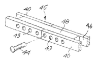
도 9는 본 발명을 구체화하는 풍력 터빈을 묘사하는 단면 사시도이며,9 is a cross-sectional perspective view depicting a wind turbine embodying the present invention,
도 10은 도 9에 도시된 본 발명의 확대 단면 정면도이며,10 is an enlarged cross-sectional front view of the present invention shown in FIG. 9,
도 11은 도 1에 도시된 본 발명을 제조하는 방법을 설명하는 블록 개략도이며,11 is a block schematic diagram illustrating a method of manufacturing the present invention shown in FIG.
도 12는 도 11의 개략도에 설명된 예시적 조립 고정구의 사시도이다.12 is a perspective view of the example assembly fixture described in the schematic view of FIG. 11.
임의의 풍력 터빈 블레이드가 주변 공기를 받아들이기에는 풍속이 너무 느린 일부 환경들이 존재한다. 다수의 예에서, 블레이드가 비교적 저속풍을 효과적으로 받아들이기엔 너무 무겁고 및/또는 너무 짧기 때문에 블레이드는 공기를 받아들여 터빈 축을 중심으로 회전할 수 없다. 임의의 과중량 및 소형의 풍력 터빈 블레이드의 중심에는 낮은 풍속 지역에서 에너지를 얻기 위해 적절한 중량과 작은 회전 관성을 제공하기에는 비효율적으로 설계된 코어 지지 구조물이 있다. 본 명세서에서 기술하는 바와 같이, 출원인은 터빈 블레이드의 구조적 필요 또는 요건을 여전히 만족시키는 감소된 중량의 블레이드를 제공하는 코어 지지 구조물을 활용하는 새로운 풍력 터빈 블레이드를 발명하였다.There are some environments where the wind speed is too slow for any wind turbine blade to receive ambient air. In many instances, the blades cannot accept air and rotate about the turbine axis because the blades are too heavy and / or too short to effectively accommodate slow winds. At the heart of any overweight and small wind turbine blade is a core support structure that is inefficiently designed to provide adequate weight and small rotational inertia for energy in low wind speed areas. As described herein, Applicants have invented a new wind turbine blade that utilizes a core support structure that provides a reduced weight blade that still meets the structural needs or requirements of the turbine blade.
도 1에 도시된 바와 같이, 본 발명의 풍력 터빈 블레이드(100)는 길이방향으로 밑면 부착부(60)로부터 끝(70)까지 축방향으로 연장되는 대체로 경량 복합 지지 트러스 구조물(20)의 효율성을 이용하는 비교적 경량의 에어포일을 포함한다. 지지 트러스 구조물(20)은 외판(90) 조립체에 의해 덮여 블레이드(100)의 기본 에어포일 형상을 형성한다. 외판(90)은 블레이드(100)의 시위 방향에서 선단 에지(74)와 후단 에지(76)를 포함한다. 블레이드(100)의 상부 캠버는 도면부호 75로 표시되고 하부 캠버는 도면부호 77로 표시된다. 예시적 모델에서, 조립 블레이드(100) 는 밑면 부착부(60)로부터 끝(70)까지 약 31m이지만, 블레이드는 풍력 발전 지역의 필요에 따라 길어질 수 있음을 알 수 있다.As shown in FIG. 1, the
도 2에서 알 수 있는 바와 같이, 풍력 터빈 블레이드의 코어는 지지 트러스 구조물(20)로 구성되며, 지지 트러스 구조물(20)은 중추부(spine; 25)를 형성하고 일반 에어포일 형상을 규정하는 풍력 터빈 블레이드(100)의 종방향 세로축을 따라 서로의 넒은 면(34)에 대체로 평행하게 배향되는 일련의 측방향으로 이격된 리브(30)들에 의해 형성된다. 리브(30)는 밑면 부착 단부(60)에서 제1 리브(30)로부터 부착 및 지지가 시작되고 끝(70)에 위치한 말단 리브(30)에서 종결되는, 복수의 연결된 복합 날개보 부재(40) 및 크로스 부재(50)에 의해 서로 지지되게 연결된다. 도 3에서 상세히 알 수 있는 바와 같이, 제1 양호한 실시예는 4개의 날개보 부재(40)를 포함하고, 이 날개보 부재는 일련의 리브(30)들을 리브의 외부 주연 에지(36)에서 서로 결합시키고 리브 접착 고정구(35)에서 리브에 연결되어 인접한 리브에 종방향 지지부에 제공한다. 복수의 크로스 부재(50)가 날개보 부재들 사이에서 지지되어 연결된다. 도 3 내지 도 5를 참고하면, 크로스 부재(50)는 기본적으로, 두 크로스 부재가 시위 방향으로 인접한 리브에 연결되고 다른 두 크로스 부재가 중추부(25)의 캠버 방향으로 인접한 리브에 지지 부착되는, 인접한 리브(30)들 사이에서 횡단하는 4개의 부재를 포함한다.As can be seen in FIG. 2, the core of the wind turbine blade consists of a
당업자들은 리브(30)가 블레이드(100)의 기본 에어포일 형상을 제공한다고 인식할 것이다. 리브(30)는 양호하게는, 발사재(balsa)의 코어와 같은 경량 재료에 섬유 유리와 같은 다른 경량 재료가 양 면에 샌드위치되어있는 상태로 가볍게 제조되고, 외주에 플랜지(37)가 포함된 약 1인치 두께의 편평 패널로서 형성된다. 예시적 블레이드 모델에서, 리브(30)들은 약 1m 떨어져서 평행하게 이격되며, 리브에 대한 외판(90)의 부착을 위한 플랜지(37) 상에서 리브 주연 에지(36)에 접착되는 외판 패널(90)에 대한 주요 지지부를 제공한다. 블레이드 표면의 다른 부분은 곡률이 변하기때문에 개개의 리브(30)는 각각의 구획에 필요한 형상과 지지부로 성형됨을 알 수 있다.Those skilled in the art will appreciate that the
날개보 부재(40)와 크로스 부재(50)는 조립시 응고된(pre-cured) 원통형펄트루젼(pultruded) 복합 재료로 제조된다. 트러스 이음부(55)는 각각의 날개보 부재(40)와 크로스 부재(50)가 각각의 리브(30)의 주연 에지(36)를 따라 각각의 접착 고정구 지점(35)에서 교차하는 곳에 형성된다. 도 2 내지 도 5에서 알 수 있는 바와 같이, 날개보 부재(40)는 밑면 부착부(60)로부터 끝(70)까지 중추부(25)의 주연 접선을 따라 연속적으로 및 기본적으로 종방향으로 곧게 진행된다. 이와 같이, 크로스 부재(50)는, 밑면 부착부(60)로부터 끝(70)까지 각각의 트러스 이음부(55)에 연결되고 인접한 리브(30)들 사이에서 중추부의 종축을 횡단하여 사선으로 엮어진, 중추부(25)의 시위 및 캠버 방향으로 연속적으로 진행되는 4개의 부재를 포함한다. 약 31m 길이의 블레이드에서는, 약 120개의 이음부가 이러한 구성으로 형성된다.The
도 6 내지 도 8을 참고하면, 제2 트러스 형성물이 도시된다. 이러한 제2 양호한 실시예에서, 트러스 지지 구조물(20)은 날개보 부재(40)와 협동하여 일련의 삼각형 트러스 이음부(57)를 형성하도록 크로스 부재(50)를 재구성함으로써 변형된다. 이러한 실시예에서, 크로스 부재(50)는 간단한 설명을 위해 각각 사선 부 재(50d) 및 수직 부재(50v)로서 재설계되지만, 어느 점으로 보아도 도 1 내지 도 5에 도시된 크로스 부재(50)와 실질적으로 동일하다. 부재(50v)는 인접한 날개보 부재들(40) 사이에서 수직으로 연결되는 크로스 부재를 가리키며, 50d로 지정된 크로스 부재는 2개의 인접한 크로스 부재(50v)를 교차하여 사선으로 결합시키는 크로스 부재를 가리킨다.6-8, a second truss formation is shown. In this second preferred embodiment, the
특히 도 6을 참조하면, 도면은 3개의 연속 트러스 이음부(57)의 평행한 일 세트를 도시하며 리브가 리브 평면(RP)으로 표현되는 중추부(25)의 단면을 묘사한다. 이러한 실시예에서 도시된 중추부(25)의 단면은, 두 쌍의 평행한 연속적인 수직 이음부를 밑면 부착부(60)로부터 끝(70)까지 형성하도록 구성되는 트러스 구조물(20)을 제외하고는 도 1 내지 도 5에 도시된 실시예와 유사하다. 이러한 도면에 따르면, 리브는 수직 부재의 플랜지(56)상에서 평행하게 진행되는 수직 부재(50v)에 부착됨을 알 수 있다. 이러한 실시예에서, 대안적 이음부의 실시예는 개별 부재(50v, 50d 및 40) 중 하나의 대안적 트러스 이음부(57)를 통합함으로써 형성된다. 필요시, 추가적인 사선 부재가 추가되어 선단 트러스 부분을 후단 트러스 부분에 부착할 수 있다.With particular reference to FIG. 6, the figure depicts a parallel set of three continuous truss seams 57 and depicts a cross section of the
제1 실시예와 달리, 크로스 부재(50v 및 50d)는 트러스 구조물(20)의 길이를 따라 유사 구성요소들로부터 분리되는 개개의 잠재적으로 교체가능한 구성요소로서 형성된다. 이러한 실시예에서, 사선 부재(50d)가 수직 부재(50v)의 상단부와, 동일한 상부 및 하부 날개보 부재(40) 세트를 따라 연결된 인접한 수직 부재(50v)의 하단부를 교차할 때, 2개의 이음부(57)가 한 쌍의 리브들 사이에서 형성된다. 도 7 및 도 8을 참고하면, 날개보 부재(40)는 수직 부재(50v)의 단부를 수용하기에 충분히 큰 폭을 지니며 일 단부로부터 다른 단부까지 진행되는 U형상 채널(46)을 포함한다. 각 수직 부재(50v)의 일 단부는 교차 사선 부재(50d)의 단부 두께를 수용하는 슬롯(54)을 포함한다. 각각의 복합 지지 부재는 볼트나 핀(42)의 삽입을 위해 중앙으로 정렬되는 보어(44)를 이음부(57)에 더 포함한다. 이음부(57)는 수직 부재(50v)의 양 측면에서 금속판(48)을 채널(46) 내에 삽입함으로써 더 강화될 수 있다. 수직 부재(50v)는 각각의 해당 리브를 플랜지에 접착시키기 위하여 부재 측면에 플랜지(56)를 더 포함한다.Unlike the first embodiment, the cross members 50v and 50d are formed as individual potentially replaceable components that are separated from similar components along the length of the
각각의 잠재적으로 교체가능한 요소로서, 리브(30), 수직 부재(50v)와 사선 부재(50d) 및 외판(90)은 보관하기 위해 분리될 수 있고 표준 40피트 선박 컨테이너로 운송될 수 있으며, 블레이드(100) 부분들은 현장에서 효과적인 분해 및 재조립에 적합하다. 도 6 및 도 6A를 참고하면, 필요시, 트러스 지지 구조물(20)은 분해된 블레이드(100)를 운송하기 위해 40피트 길이보다 짧은 간격으로 구성되는 변형된 날개보 부재(40)를 포함할 수 있다. 날개보 부재(40)를 리브(30)에 조립할 때, 임의의 트러스 이음부(57)의 중간의 각 날개보 부재(40)의 단부들에 첨접 이음부(splice joint; 45)를 형성함으로써 구조적 단일성 및 일체성이 보전될 수 있다. 이러한 예에서, 각각의 날개보 부재 단부는 U형상 채널(46)을 가로질러 서로 정렬되는 날개보 부재 측벽에 복수의 보어(43)를 포함한다. 강철 또는 다른 유사한 강한 물질로 제조된 가교 부재(48)는 U형상 채널(46) 내에 가압 끼움되어 축방향으로 인접하는 두 날개보 부재(20)의 각 단부들을 서로 횡단하고 겹쳐 잇는다. 또한, 가교 부재(48)는 날개보 부재(40)의 각각의 보어와 정렬된 보어(43)를 포함한다. 이후, 각각의 날개보 부재 단부는 핀(44)이 날개보 부재(40)와 가교 부재(48)의 각 정렬된 보어를 통해 삽입됨으로써 서로 고정 및 접합되어 첨접 이음부(45)를 형성한다. 가교 부재(48)의 크기는 최소로 유지되어, 트러스 구조물의 경량 특성을 보전하면서 구획화된 날개보 부재(20)의 부하 능력을 유지한다. 또한, 날개보 부재(40)는 각각의 이음부 완전성을 유지하기 위하여, 임의의 트러스 이음부들(57)로부터 중간의 미리 결정된 거리에서 날개보 부재들이 서로 겹쳐 이어지게 하는 길이로 종결된다.As each potentially replaceable element, the
일단 조립되면, 터빈 블레이드(100)는 도 9 내지 도 10에 보이는 바와 같은 상용 풍력 터빈(99)에 쉽게 부착가능한 견고하면서도 경량인 에어포일 구조물을 제공한다. 외판 패널(90)은 대량으로 제조될 수 있는 편평 패널 섬유유리로 구성되어 이로부터 형상화되며, 또는 이와 달리, 트러스 구조물(20)은 곡률이 변하는 영역에 적합한 직물로 덮일 수 있으며, 이후, 이러한 직물은 수지를 통해 경화되어 블레이드 에어포일을 완성시킨다. 블레이드의 구성에 있어서, 외판(90)은 트러스 구조물(20)의 주위를 둘러싸며 플랜지(37)에 대해 각각의 리브 주연 에지(36)에서 리브(30)에 고정된다. 당업자는 접착제를 사용한 접착과 같은 종래 접착 기술 또는 기계적 체결구의 사용이 외판(90)을 리브(30)에 부착시키는 데 적절하다는 것을 알 것이다. 또한, 리브(30)가 높은 곡률의 영역을 형성하는 경우에는 외판 패널(90)이 단일 리브 쌍에 걸쳐 연장될 수 있음을 알 수 있다. 그러나, 작은 곡률의 영역에서는, 몇몇의 리브가 외판 패널(90)의 큰 부분으로 덮일 수 있다. 일단, 외판(90)이 트러스 구조물(20)에 장착 및 접착되면, 외판(90)은 단일 연속 외판으로서 거동하므로, 풍력 부하를 허브(72, 도 9 및 도 10 참조)로 전달하기 위해 밑면 부착 단부(60)로부터 장착될 수 있는 일체형 구조로서 블레이드(100)의 내부 요소들을 지지할 수 있다.Once assembled, the
밑면 부착 단부(60)는 칼라로부터 외향 돌출되는 4개의 경질 지점(hard point; 87)을 지닌 칼라(85)를 내포하는 강철 장착 링(80)을 포함함으로써 현용의 풍력 터빈 허브와의 호환성을 유지한다. 4개의 날개보 부재(40)는 경질 지점의 내부에 부착된다. 외판(90)은 날개보 부재(40), 경질 지점(87) 및 칼라(85) 위에 덮인다. 조립부 단부(60)는 장착 링(80)이 볼트를 이용하여 허브(72)에 볼트로 조여짐으로써 풍력 터빈(99)에 고정된다. 일단 장착되면, 날개보 부재(40)가 주요 부하 지지체지만, 밑면 부착 단부(60)에서는 연속 외판(90)이 허브(72)로 전달하기 위해 부하를 지지한다.The
작동시, 바람이 블레이드(100) 표면을 가로지를 때, 풍력은 블레이드에 작용하여 블레이드를 회전시키는 허브를 중심으로 한 토크를 생성한다. 블레이드(100)가 회전할 때 블레이드가 그 원형 경로를 지속적으로 통과하므로, 전단력 및 굴곡력(bendging force)이 블레이드 상에 작용한다. 당업자들은 힘들이 블레이드 상에 작용할 때, 날개보 부재(40)가 대부분의 굴곡력 부하를 지탱하는 반면, 크로스 부재(50)는 전단응력 및 염력(torsional) 지지부를 제공함을 인식할 것이다. 따라서, 설명된 트러스 구조물(20)은 표준 길이(예컨대, 약 100피트)의 경량 블레이드를 생산하도록 활용될 수 있거나, 또는, 더 큰 원호의 회전 면적으로부터 풍력을 얻을 수 있는 현재 설계와 유사한 중량을 지닌 길이가 긴 블레이드를 생산하는 데 사용될 수 있다.In operation, when the wind crosses the surface of the
트러스 구조물(20)에서 복합 요소를 사용함으로써, 충분한 강도 성능(strength performance)과 피로 저항(fatigue resistance)이 달성되면서 비교적 저밀도의 구조물에 블레이드의 강성 지지부를 제공한다. 복합 날개보 부재(40) 및/또는 크로스 부재(50)을 사용함으로써, 이러한 경량 복합 구성요소는 측방향으로 이격된 리브(30)와 협동하는 트러스 이음부(55)의 주요 부하 경로를 구성한다. 또한, 지지 부재를 매우 단향성으로 제조하게 하는 제조법(fabrication)을 사용함으로써, 섬유는 제조물의 축 방향을 따라 곧게 정렬되어, 부재 내에서 보강(reinforcement) 및 균일 강도를 제공한다. 따라서, 유닛 길이당 적은 재료 중량을 형성하며 블레이드(100) 내에 비교적 넓은 부분의 빈 공간(empty space)을 제공하는, 지지되고 보강된 구조물이 설명된다. 전반적으로, 제안된 트러스 구조물(20)을 사용하는 100피트 블레이드의 중량은 (12,000파운드의 현재 종래기술의 섬유유리 블레이드와 비교하면) 6,000파운드 만큼 적게 나가므로 임의의 섬유유리 블레이드에 비해 50% 중량 감소까지 초래할 수 있다. 블레이드의 보강이 요구되는 경우, 블레이드(100)의 총 중량에 크게 영향을 미치지 않고 부하 경로 보강을 위해 추가적인 크로스 부재(50)와 날개보 부재(40)가 추가될 수 있음이 이해될 것이다.By using a composite element in the
또한, 현재 종래기술의 섬유유리 블레이드는 100피트를 초과하는 길이로 제조될 때 동력을 생산하는 데 다소 너무 무겁고 비효율적인 것으로 간주된다. 반대로, 블레이드(100)의 유닛 길이 당 중량은 비교적 가벼우며, 또한, 풍차(wind mill; 99)는 더 적은 중량 부하를 유지하면서 더 큰 스위핑 원호(sweeping arc)의 풍역을 덮을 수 있는 긴 길이로 구성된 블레이드(100)로부터 이익을 얻을 수 있다. 낮은 풍력 지역에서, 더 큰 원호로 회전하는 길이가 긴 블레이드는 더 많은 풍력을 얻을 수 있으므로 더 많은 동력을 생산할 수 있다. 또한, 경량 블레이드(100)는 허브(72)에 중량 부하를 적게 가하므로, 더 적은 응력이 허브, 터빈, 베어링 및 타워에 가해지는 것이 이해될 것이다. 블레이드(100)를 포함하는 풍차(99)는 약 30% 내지 약 40% 감소된 순 에너지 비용으로 작동하면서 5 메가와트까지 동력을 생산할 것으로 기대된다.In addition, fiberglass blades of the prior art are now considered somewhat too heavy and inefficient in producing power when manufactured to lengths in excess of 100 feet. In contrast, the weight per unit length of the
또한, 제안된 발명은 풍력 터빈 블레이드를 제조하는 경제적인 공정에 적합하다. 도 11 및 도 12를 참고하면, 블레이드의 형상을 형성하도록 정렬된 리브(30) 집합체를 선택하는 단계를 포함하는 과정이 기술된다. 복합 부분들은 조립 전에 제조되고 응고된다. 지주(88) 세트는 지면 또는 고정구 상에 미리 결정된 거리로 이격되며 리브(30)는 지주에 장착된다. 이후, 복합 날개보 부재(40)는 밑면으로부터 끝까지 리브 주연 에지(36)를 따라 장착 고정구(86 및 87)에 부착된다. 이후, 밑면에서 시작되어 끝으로 이동하면서, 복합 크로스 부재(50)는 트러스 이음부(55)를 형성하면서 상부 진행 날개보와 하부 진행 날개보(40) 사이에 부착된다. 이후, 외판이 트러스 구조물(20)에 적용되어 블레이드를 완성한다. 외판은 소정 형상으로 절단된 (약 2겹의) 얇은 2축성 함침복합재(prepreg) 섬유유리로부터 제조되거나, 열 수축되어 공력 끼움(aerodynamic fit)되고 수지로 코팅된 직물로 구조물을 덮음으로써 제조될 수 있다.The proposed invention is also suitable for economical processes for manufacturing wind turbine blades. Referring to Figures 11 and 12, a process is described that includes selecting a collection of
본 명세서에 기술한 바와 같이, 본 발명의 블레이드(100)는 에너지 효율적인 발전을 생산하는데 유용한 경량의 견고한 구성을 제공하는 새롭고 유용한 구조물을 설명한다.As described herein, the
Claims (20)
Applications Claiming Priority (2)
| Application Number | Priority Date | Filing Date | Title |
|---|---|---|---|
| US11/725,916 | 2007-03-20 | ||
| US11/725,916 US7517198B2 (en) | 2006-03-20 | 2007-03-20 | Lightweight composite truss wind turbine blade |
Publications (1)
| Publication Number | Publication Date |
|---|---|
| KR20100015691A true KR20100015691A (en) | 2010-02-12 |
Family
ID=39766206
Family Applications (1)
| Application Number | Title | Priority Date | Filing Date |
|---|---|---|---|
| KR1020097021783A KR20100015691A (en) | 2007-03-20 | 2007-09-13 | Lightweight composite truss wind turbine blade |
Country Status (11)
| Country | Link |
|---|---|
| US (5) | US7517198B2 (en) |
| EP (1) | EP2134963B1 (en) |
| JP (1) | JP5323050B2 (en) |
| KR (1) | KR20100015691A (en) |
| CN (1) | CN101715514A (en) |
| AU (1) | AU2007349286A1 (en) |
| BR (1) | BRPI0721453A2 (en) |
| CA (1) | CA2681469A1 (en) |
| DK (1) | DK2134963T3 (en) |
| MX (1) | MX2009010063A (en) |
| WO (1) | WO2008115265A1 (en) |
Families Citing this family (105)
| Publication number | Priority date | Publication date | Assignee | Title |
|---|---|---|---|---|
| GB0426944D0 (en) * | 2004-12-08 | 2005-01-12 | Airbus Uk Ltd | A trussed structure |
| US20090178605A1 (en) * | 2005-01-21 | 2009-07-16 | Tufte Brian N | Cover system for a boat |
| US7439712B2 (en) * | 2006-02-21 | 2008-10-21 | Mccowen Clint | Energy collection |
| US7517198B2 (en) | 2006-03-20 | 2009-04-14 | Modular Wind Energy, Inc. | Lightweight composite truss wind turbine blade |
| EP2021626A4 (en) * | 2006-05-30 | 2013-08-07 | Analytical Design Service Corp | Vertical axis wind system |
| CN101646865B (en) * | 2006-12-15 | 2013-01-09 | 布拉德纳公司 | Reinforced aerodynamic profile |
| WO2008086805A2 (en) | 2007-01-16 | 2008-07-24 | Danmarks Tekniske Universitet | Reinforced blade for wind turbine |
| US8632312B2 (en) * | 2007-01-25 | 2014-01-21 | Bladena Aps | Reinforced blade for wind turbine |
| CN101595300A (en) * | 2007-01-29 | 2009-12-02 | 丹麦技术大学 | Wind turbine blade |
| ES2322423B1 (en) * | 2007-06-21 | 2010-01-26 | Manuel Torres Martinez | HORIZONTAL SHAFT AEROGENERATOR SHOVEL. |
| EP2203647A1 (en) * | 2007-10-04 | 2010-07-07 | Bronswerk Heat Transfer B.V. | Fan |
| US8733549B2 (en) † | 2007-11-13 | 2014-05-27 | General Electric Company | System for containing and/or transporting wind turbine components |
| US20090140527A1 (en) * | 2007-11-30 | 2009-06-04 | General Electric Company | Wind turbine blade stiffeners |
| US20110176928A1 (en) * | 2008-06-23 | 2011-07-21 | Jensen Find Moelholt | Wind turbine blade with angled girders |
| US8807953B2 (en) * | 2008-06-24 | 2014-08-19 | Bladena Aps | Reinforced wind turbine blade |
| US20090324416A1 (en) * | 2008-06-30 | 2009-12-31 | Ge Wind Energy Gmbh | Wind turbine blades with multiple curvatures |
| ES2341074B1 (en) * | 2008-10-28 | 2011-05-20 | GAMESA INNOVATION & TECHNOLOGY, S.L | A MULTI-PANEL AEROGENERATOR SHOVEL WITH INTEGRATED ROOT. |
| US8510947B2 (en) * | 2008-11-14 | 2013-08-20 | General Electric Company | Turbine blade fabrication |
| US20100122459A1 (en) * | 2008-11-17 | 2010-05-20 | General Electric Company | Method of making wind turbine blade |
| JP5656861B2 (en) | 2008-12-05 | 2015-01-21 | モジュラー ウィンド エナジー インコーポレイテッド | EFFICIENT WIND TURBINE BLADE, WIND TURBINE BLADE STRUCTURE, AND RELATED SYSTEM AND METHOD OF MANUFACTURING, ASSEMBLY AND USE |
| GB2467745A (en) | 2009-02-11 | 2010-08-18 | Vestas Wind Sys As | Wind turbine blade with tension element(s) to increase edgewise stiffness |
| CN101555872A (en) * | 2009-02-20 | 2009-10-14 | 宜兴市华泰国际集团工业有限公司 | Blade of MW class wind turbine |
| ES2575996T3 (en) * | 2009-04-13 | 2016-07-04 | Maxiflow Manufacturing Inc. | Wind turbine blade and its manufacturing method |
| US8753091B1 (en) | 2009-05-20 | 2014-06-17 | A&P Technology, Inc. | Composite wind turbine blade and method for manufacturing same |
| WO2010147840A2 (en) * | 2009-06-19 | 2010-12-23 | University Of Miami | Wind energy system |
| US20110100540A1 (en) * | 2009-10-30 | 2011-05-05 | General Electric Company | Methods of manufacture of wind turbine blades and other structures |
| US20110103965A1 (en) * | 2009-10-30 | 2011-05-05 | General Electric Company | Wind turbine blades |
| CN102052239A (en) * | 2009-11-05 | 2011-05-11 | 上海神飞能源科技有限公司 | Vertical axis wind motor |
| EP2330294B1 (en) | 2009-12-02 | 2013-01-16 | Bladena ApS | Reinforced airfoil shaped body |
| US8550786B2 (en) * | 2009-12-11 | 2013-10-08 | Peter Janiuk | Vertical axis wind turbine with self-starting capabilities |
| US20110135485A1 (en) * | 2009-12-30 | 2011-06-09 | Jing Wang | Spar for a wind turbine rotor blade and method for fabricating the same |
| ES2510398T3 (en) | 2010-01-14 | 2014-10-21 | Neptco, Inc. | Wind turbine rotor blade components and methods for manufacturing them |
| US10137542B2 (en) | 2010-01-14 | 2018-11-27 | Senvion Gmbh | Wind turbine rotor blade components and machine for making same |
| JP2013519022A (en) * | 2010-02-08 | 2013-05-23 | 国能風力発電有限公司 | High efficiency, high power vertical axis wind power generator |
| EP2534374A4 (en) * | 2010-02-12 | 2017-12-27 | Thomas Holding Århus A/s | Foam members and a spar are assembled then coated and finished to form a blade for a wind turbine |
| US9228564B2 (en) | 2010-02-25 | 2016-01-05 | The Regents Of The University Of California | Integrated wind turbine |
| DE102010013405B4 (en) * | 2010-03-30 | 2019-03-28 | Wobben Properties Gmbh | Rotor blade for making a rotor blade of a wind turbine |
| US8192169B2 (en) * | 2010-04-09 | 2012-06-05 | Frederick W Piasecki | Highly reliable, low cost wind turbine rotor blade |
| JP2013526681A (en) * | 2010-05-24 | 2013-06-24 | モジュラー ウィンド エナジー インコーポレイテッド | Segmented wind turbine blades with truss coupling regions and related systems and methods |
| US9500179B2 (en) * | 2010-05-24 | 2016-11-22 | Vestas Wind Systems A/S | Segmented wind turbine blades with truss connection regions, and associated systems and methods |
| NZ585881A (en) * | 2010-06-02 | 2010-10-29 | Aquadria Kite Design Ltd | Inflatable wing for traction kite with inflatable spar spaced from leading edge |
| NZ587521A (en) * | 2010-06-02 | 2010-10-29 | Aquadria Kite Design Ltd | An inflatable wing with inflatable leading edge spar and rib(s) from spar to trailing edge in form of inflatable truss(es) |
| US8043066B2 (en) * | 2010-06-08 | 2011-10-25 | General Electric Company | Trailing edge bonding cap for wind turbine rotor blades |
| CN102278274A (en) * | 2010-06-11 | 2011-12-14 | 大银微系统股份有限公司 | Combined type blade used for vertical wind driven generator |
| EP2400147A1 (en) * | 2010-06-25 | 2011-12-28 | Siemens Aktiengesellschaft | Root of the blade of a wind turbine |
| FR2963066B1 (en) * | 2010-07-20 | 2012-08-31 | Alizeo | Blade for wind turbine and wind turbine with such a blade. |
| DE102010038719A1 (en) | 2010-07-30 | 2012-04-19 | Baltico Gmbh | Bar-wound structure in composite construction |
| ES2398553B1 (en) * | 2011-02-24 | 2014-02-06 | Gamesa Innovation & Technology S.L. | A MULTI-PANEL IMPROVED AIRPLANE SHOVEL. |
| US8358030B2 (en) | 2011-03-17 | 2013-01-22 | Via Verde Limited | Wind turbine apparatus |
| US8360732B2 (en) * | 2011-05-25 | 2013-01-29 | General Electric Company | Rotor blade section and method for assembling a rotor blade for a wind turbine |
| CN102294574B (en) * | 2011-08-01 | 2013-04-17 | 北京市拓又达科技有限公司 | Vertical shaft large blade forming machine |
| DE102011114247A1 (en) * | 2011-09-26 | 2013-03-28 | Repower Systems Se | Rotary drive for a rotor of a wind energy plant |
| ITRM20110517A1 (en) * | 2011-09-30 | 2013-03-31 | Enel Green Power Spa | SHOVEL FOR WIND GENERATOR AND ASSEMBLY METHOD OF THAT SHAFT |
| US8500406B2 (en) | 2011-12-22 | 2013-08-06 | General Electric Company | Wind turbine rotor blades with shape memory polymer composites and methods for deploying the same |
| CN102588224A (en) * | 2012-03-16 | 2012-07-18 | 西南交通大学 | Hollow fan blade of wind generator |
| US20130309095A1 (en) * | 2012-05-17 | 2013-11-21 | SkyWolf Wind Turbine Corp. | Wind turbine blade having improved structural and aerodynamic characteristics |
| EP2679804A1 (en) * | 2012-10-26 | 2014-01-01 | LM WP Patent Holding A/S | A wind turbine blade having an inner truss element |
| US20140119937A1 (en) * | 2012-10-31 | 2014-05-01 | General Electric Company | Wind turbine rotor blade with fabric skin and associated method for assembly |
| US20140119933A1 (en) * | 2012-10-31 | 2014-05-01 | General Electric Company | Wind turbine rotor blade with fabric skin and associated attachment method |
| US9188102B2 (en) * | 2012-10-31 | 2015-11-17 | General Electric Company | Wind turbine blades with tension fabric skin structure |
| JP6126823B2 (en) * | 2012-11-19 | 2017-05-10 | エグチホールディングス株式会社 | Blade for wind power generator and manufacturing method thereof |
| US9605650B2 (en) * | 2012-12-04 | 2017-03-28 | General Electric Company | Wind blades with mechanical elements for pretensioning in tension fabrics |
| CN103089553A (en) * | 2013-01-17 | 2013-05-08 | 清华大学 | Articulated truss fixed variable pitch combined blade device |
| US9534580B2 (en) | 2013-02-27 | 2017-01-03 | General Electric Company | Fluid turbine blade with torsionally compliant skin and method of providing the same |
| US9297357B2 (en) | 2013-04-04 | 2016-03-29 | General Electric Company | Blade insert for a wind turbine rotor blade |
| US20150003991A1 (en) * | 2013-06-28 | 2015-01-01 | General Electric Company | Modular extensions for wind turbine rotor blades |
| US9506452B2 (en) | 2013-08-28 | 2016-11-29 | General Electric Company | Method for installing a shear web insert within a segmented rotor blade assembly |
| US9664174B2 (en) * | 2013-11-22 | 2017-05-30 | General Electric Company | Aerodynamic root adapters for wind turbine rotor blades |
| EP3086924A1 (en) * | 2013-12-23 | 2016-11-02 | Vestas Wind Systems A/S | Wind turbine blades |
| EP2927481B1 (en) * | 2014-03-31 | 2021-09-22 | Siemens Gamesa Renewable Energy A/S | Rotor blade for a wind turbine |
| US9651024B2 (en) * | 2014-04-14 | 2017-05-16 | General Electric Company | Rotor blade assembly having internal loading features |
| ES2748702T3 (en) | 2014-09-25 | 2020-03-17 | Winfoor Ab | Rotor blade for wind turbine |
| US10006436B2 (en) | 2014-12-18 | 2018-06-26 | General Electric Company | Wind turbine rotor blades with load-transferring exterior panels |
| CN104728056B (en) * | 2015-03-27 | 2018-04-13 | 丁健威 | A kind of blade of wind-driven generator of Combined bamboo offset plate structure |
| US10337490B2 (en) | 2015-06-29 | 2019-07-02 | General Electric Company | Structural component for a modular rotor blade |
| US9897065B2 (en) | 2015-06-29 | 2018-02-20 | General Electric Company | Modular wind turbine rotor blades and methods of assembling same |
| US10077758B2 (en) | 2015-06-30 | 2018-09-18 | General Electric Company | Corrugated pre-cured laminate plates for use within wind turbine rotor blades |
| US10072632B2 (en) | 2015-06-30 | 2018-09-11 | General Electric Company | Spar cap for a wind turbine rotor blade formed from pre-cured laminate plates of varying thicknesses |
| DE102015010453B4 (en) * | 2015-08-10 | 2021-10-21 | Enbreeze Gmbh | Wings for wind turbines, rotors of helicopters or wings of small aircraft and processes for their production |
| US10107257B2 (en) | 2015-09-23 | 2018-10-23 | General Electric Company | Wind turbine rotor blade components formed from pultruded hybrid-resin fiber-reinforced composites |
| DE102015116634A1 (en) * | 2015-10-01 | 2017-04-06 | Wobben Properties Gmbh | Wind turbine rotor blade and wind turbine |
| US10113532B2 (en) | 2015-10-23 | 2018-10-30 | General Electric Company | Pre-cured composites for rotor blade components |
| CN105649868B (en) * | 2016-01-22 | 2018-06-15 | 清华大学 | Intensifier outside a kind of wind turbine blade face based on wing fence Tiebar structure |
| EP3222846A1 (en) | 2016-03-24 | 2017-09-27 | Winfoor AB | Wind turbine rotor blade |
| DK3225841T3 (en) * | 2016-03-31 | 2022-01-10 | Nordex Energy Spain S A | PROCEDURE FOR BALANCING THE WIND TURBINE ROTOR, ASSOCIATED SYSTEM AND WIND TURBINE |
| NL2016888B1 (en) | 2016-06-02 | 2018-01-12 | Ibis Power Holding B V | Electric power system for converting wind energy into electric energy and building with system |
| KR101694432B1 (en) * | 2016-06-21 | 2017-01-09 | 한국항공대학교산학협력단 | Blade for wind power generator |
| US10422316B2 (en) | 2016-08-30 | 2019-09-24 | General Electric Company | Pre-cured rotor blade components having areas of variable stiffness |
| EP3535488B1 (en) * | 2016-11-01 | 2021-06-16 | Vestas Wind Systems A/S | Shear web for a wind turbine blade |
| CN106593948A (en) * | 2016-12-13 | 2017-04-26 | 惠阳航空螺旋桨有限责任公司 | Combined type wing beam blade |
| DE102016014908A1 (en) * | 2016-12-14 | 2018-06-14 | Senvion Gmbh | Rotor blade, wind turbine with a rotor blade and repair kit and method for reinforcing a rotor blade |
| US20200011291A1 (en) * | 2016-12-21 | 2020-01-09 | Siemens Gamesa Renewable Energy A/S | Wind tubine blade with variable deflection-dependent stiffness |
| US10850826B2 (en) | 2017-03-24 | 2020-12-01 | The Boeing Company | Aircraft wing space frame |
| CN106884758A (en) * | 2017-03-29 | 2017-06-23 | 大连理工大学 | A kind of device for changing hydraulic turbine rotary inertia according to rotating speed |
| EP3412906A1 (en) | 2017-06-08 | 2018-12-12 | Winfoor AB | A wind turbine rotor blade, a section thereof and an interconnecting member |
| US10920743B2 (en) | 2017-08-17 | 2021-02-16 | General Electric Company | Misaligned spar cap scarf joint connection |
| CN109931211A (en) * | 2017-12-19 | 2019-06-25 | 天津松英科技发展有限公司 | High stability protective device for blade of wind-driven generator |
| CN110953112B (en) * | 2018-09-27 | 2021-03-23 | 大连理工大学 | Vertical shaft blade and forming method thereof |
| CN111486362B (en) * | 2019-01-25 | 2022-03-11 | 联合通达国际有限公司 | Combined lamp |
| US10697437B1 (en) * | 2019-08-27 | 2020-06-30 | Bnsf Logistics, Llc | Rotatable support fixture for wind turbine blade |
| US11739645B2 (en) | 2020-09-30 | 2023-08-29 | General Electric Company | Vibrational dampening elements |
| US11536144B2 (en) | 2020-09-30 | 2022-12-27 | General Electric Company | Rotor blade damping structures |
| CN112943565B (en) * | 2021-03-16 | 2021-12-28 | 中国华能集团清洁能源技术研究院有限公司 | Fan blade with wave-shaped vortex generator and design method thereof |
| US20240076989A1 (en) * | 2022-09-06 | 2024-03-07 | General Electric Company | Airfoil assembly with tensioned blade segments |
| CN115217713B (en) * | 2022-09-21 | 2022-11-29 | 山东金科星机电股份有限公司 | Deformable fan blade structure of wind driven generator |
Family Cites Families (90)
| Publication number | Priority date | Publication date | Assignee | Title |
|---|---|---|---|---|
| US1517546A (en) * | 1924-12-02 | Land and water flying machine | ||
| US1325499A (en) * | 1919-12-16 | Wings and the like | ||
| US1291678A (en) * | 1916-03-31 | 1919-01-14 | Curtiss Aeroplane & Motor Co | Wing construction. |
| US1397701A (en) * | 1917-11-19 | 1921-11-22 | Rapp | Airplane-rib construction |
| US1453114A (en) * | 1917-12-19 | 1923-04-24 | Rapp | Airplane-rib construction |
| US1403444A (en) * | 1917-12-31 | 1922-01-10 | Rapp | Airplane-wing construction |
| US1337951A (en) * | 1918-10-11 | 1920-04-20 | Kawneer Mfg Company | Aeroplane-wing construction |
| US1388543A (en) * | 1920-07-03 | 1921-08-23 | Walter H Barling | Rib for airplane-wings and the like |
| US1758360A (en) * | 1926-03-05 | 1930-05-13 | Julius S Fox | Aeroplane wing structure |
| US1852622A (en) * | 1927-06-09 | 1932-04-05 | Glenn L Martin Co | Airplane wing structure |
| US1833696A (en) * | 1929-10-26 | 1931-11-24 | Wallis Barnes Neville | Structure of wings for aircraft |
| US1949785A (en) * | 1930-04-29 | 1934-03-06 | Autogiro Co Of America | Aircraft having freely rotative wings |
| GB382979A (en) | 1931-08-28 | 1932-11-10 | A T S Company Ltd | Improvements in or connected with the construction of ribs for aircraft wings |
| GB448249A (en) | 1933-12-09 | 1936-06-04 | Charles Hampson Grant | Improvements relating to internally trussed structures which are capable of flexing longitudinally |
| DE630297C (en) * | 1934-06-16 | 1936-05-25 | Arthur Levell | Single-spar aircraft wing |
| GB466665A (en) | 1935-12-03 | 1937-06-02 | Leslie Everett Baynes | Improvements in and relating to the construction of aircraft wings |
| US2219454A (en) * | 1938-07-16 | 1940-10-29 | Frank C Reilly | Cosmetic holder |
| US2386019A (en) * | 1943-01-28 | 1945-10-02 | Budd Edward G Mfg Co | Truss structure and parts thereof |
| GB582527A (en) | 1943-01-28 | 1946-11-20 | Budd Edward G Mfg Co | Improvements in or relating to a truss structure particularly for aircraft |
| US2405917A (en) * | 1943-01-28 | 1946-08-13 | Budd Edward G Mfg Co | Strut element and joint |
| SE315526B (en) * | 1968-07-11 | 1969-09-29 | Karlstad Mekaniska Ab | |
| FR2345600A1 (en) * | 1975-06-09 | 1977-10-21 | Bourquardez Gaston | FLUID BEARING WIND TURBINE |
| US4130380A (en) * | 1976-05-13 | 1978-12-19 | Kaiser Heinz W | Wind powered turbine and airfoil construction |
| US4193005A (en) * | 1978-08-17 | 1980-03-11 | United Technologies Corporation | Multi-mode control system for wind turbines |
| DE2921152C2 (en) * | 1979-05-25 | 1982-04-22 | Messerschmitt-Bölkow-Blohm GmbH, 8000 München | Rotor blade for wind power plants |
| US4295790A (en) * | 1979-06-21 | 1981-10-20 | The Budd Company | Blade structure for use in a windmill |
| US4339230A (en) * | 1980-04-22 | 1982-07-13 | Hercules Incorporated | Bifoil blade |
| GB2168111B (en) * | 1984-12-08 | 1988-05-18 | Rolls Royce | Rotor aerofoil blade containment |
| FR2588822B1 (en) | 1985-10-22 | 1988-08-26 | Courthieu Sa Georges | WING FOR LIGHT AIRCRAFT |
| US4815939A (en) * | 1986-11-03 | 1989-03-28 | Airfoil Textron Inc. | Twisted hollow airfoil with non-twisted internal support ribs |
| DE3708445A1 (en) | 1987-03-16 | 1988-09-29 | Albrecht Prof Dr Fischer | Wing for ultralight aircraft |
| NL8800386A (en) | 1988-02-16 | 1989-09-18 | Fokker Aircraft | Air-ducted construction for aircraft - uses jig with reinforced strips and supporting strut |
| JPH01145985U (en) * | 1988-03-31 | 1989-10-06 | ||
| WO1991015399A1 (en) * | 1990-03-30 | 1991-10-17 | Ferdinand Lutz | Propeller with twistable blades |
| JP2808500B2 (en) * | 1991-08-23 | 1998-10-08 | 三菱重工業株式会社 | Gas turbine hollow fan blades |
| US5392514A (en) * | 1992-02-06 | 1995-02-28 | United Technologies Corporation | Method of manufacturing a composite blade with a reinforced leading edge |
| US5219454A (en) * | 1992-04-22 | 1993-06-15 | Denis Class | Method and apparatus for balancing wind turbine rotors |
| US5269058A (en) * | 1992-12-16 | 1993-12-14 | General Electric Company | Design and processing method for manufacturing hollow airfoils |
| US5509783A (en) * | 1993-02-09 | 1996-04-23 | Preci-Spark, Ltd. | Reinforced vane |
| US5375324A (en) * | 1993-07-12 | 1994-12-27 | Flowind Corporation | Vertical axis wind turbine with pultruded blades |
| US5628403A (en) * | 1996-01-16 | 1997-05-13 | Bill Thomas Associates, Inc. | Universal turbine blade packaging container |
| JP2000006893A (en) * | 1998-06-23 | 2000-01-11 | Fuji Heavy Ind Ltd | Composite material wing structure |
| US6146097A (en) * | 1998-09-14 | 2000-11-14 | Bradt; Gordon E. | Fan blade assembly for use with a ceiling fan drive unit |
| ES2178903B1 (en) * | 1999-05-31 | 2004-03-16 | Torres Martinez M | SHOVEL FOR AEROGENERATOR. |
| US6513757B1 (en) | 1999-07-19 | 2003-02-04 | Fuji Jukogyo Kabushiki Kaisha | Wing of composite material and method of fabricating the same |
| WO2002014688A1 (en) * | 2000-08-17 | 2002-02-21 | Hongsun Hua | Windmill |
| DE10152449A1 (en) | 2001-10-26 | 2003-05-15 | Aloys Wobben | Rotor blade for wind turbine is fitted with system for altering its surface, e.g. pivoting flap or section of rotor which can be wound up on to core |
| JP2004535527A (en) * | 2001-07-19 | 2004-11-25 | エンエーゲー ミコン アクティーゼルスカブ | Wind turbine blade |
| JP3368537B1 (en) * | 2001-11-08 | 2003-01-20 | 学校法人東海大学 | Straight wing type windmill |
| DE10262308B4 (en) * | 2002-01-08 | 2009-02-05 | Aloys Wobben | Device for handling piece goods |
| DK175718B1 (en) * | 2002-04-15 | 2005-02-07 | Ssp Technology As | Möllevinge |
| US6972498B2 (en) * | 2002-05-28 | 2005-12-06 | General Electric Company | Variable diameter wind turbine rotor blades |
| US7160083B2 (en) * | 2003-02-03 | 2007-01-09 | General Electric Company | Method and apparatus for wind turbine rotor load control |
| US7510366B2 (en) * | 2003-06-09 | 2009-03-31 | Shinko Electric Co., Ltd. | Vertical axis type wind power station |
| US6890152B1 (en) | 2003-10-03 | 2005-05-10 | General Electric Company | Deicing device for wind turbine blades |
| US7127189B2 (en) * | 2003-12-08 | 2006-10-24 | Ricoh Company, Ltd. | Heating unit, auxiliary power unit, fixing unit, and image forming apparatus |
| FR2864175B1 (en) | 2003-12-22 | 2008-03-28 | Airbus | WIND TURBINE |
| JP4580169B2 (en) * | 2004-02-05 | 2010-11-10 | 富士重工業株式会社 | Split blade for windmill and lightning protection device for windmill |
| JP2005282451A (en) * | 2004-03-30 | 2005-10-13 | Ishikawajima Harima Heavy Ind Co Ltd | Wind power generator |
| EP1584817A1 (en) | 2004-04-07 | 2005-10-12 | Gamesa Eolica, S.A. (Sociedad Unipersonal) | Wind turbine blade |
| JP2005299620A (en) | 2004-04-08 | 2005-10-27 | Makku:Kk | Method of separation and standardized production of wind power generation blade |
| ES2375564T3 (en) | 2004-06-30 | 2012-03-02 | Vestas Wind Systems A/S | ASPAS OF WIND TURBINES CONSTITUTED BY TWO SEPARATE SECTIONS. |
| US7118338B2 (en) | 2004-06-30 | 2006-10-10 | General Electric Company | Methods and apparatus for twist bend coupled (TCB) wind turbine blades |
| GB0415545D0 (en) | 2004-07-12 | 2004-08-11 | Peace Steven | Wind turbine |
| US8419362B2 (en) * | 2004-08-31 | 2013-04-16 | Hamilton Sundstrand Corporation | Foldable blades for wind turbines |
| GB0426944D0 (en) | 2004-12-08 | 2005-01-12 | Airbus Uk Ltd | A trussed structure |
| US7153090B2 (en) * | 2004-12-17 | 2006-12-26 | General Electric Company | System and method for passive load attenuation in a wind turbine |
| ES2289613T3 (en) * | 2005-02-24 | 2008-02-01 | Vestas Wind Systems A/S | METHOD FOR MANUFACTURING A WIND TURBINE SHOVEL, WIND TURBINE WATER MANUFACTURING INSTALLATION AND USE OF THE SAME. |
| JP2006274965A (en) * | 2005-03-30 | 2006-10-12 | Shirahama Machi | Vertical shaft windmill and power generation system |
| ES2265760B1 (en) | 2005-03-31 | 2008-01-16 | GAMESA INNOVATION & TECHNOLOGY, S.L. | SHOVEL FOR WIND GENERATORS. |
| US20060225278A1 (en) * | 2005-03-31 | 2006-10-12 | Lin Wendy W | Wind blade construction and system and method thereof |
| ES2263389B1 (en) | 2005-06-03 | 2007-12-01 | Esdras Automaticas, S.L. | STRUCTURE OF SUBALABES FOR REDUCTION OF THE WEIGHT OF LAS PALAS IN EOLIC TURBINES. |
| JP2007030702A (en) * | 2005-07-27 | 2007-02-08 | Megumi Fujii | Ram wing shape supporting device, ram wing using ram wing shape supporting device, flying device and generator using ram wing, control device of ram wing and foot launch type flying device |
| US7637721B2 (en) * | 2005-07-29 | 2009-12-29 | General Electric Company | Methods and apparatus for producing wind energy with reduced wind turbine noise |
| DK1754886T3 (en) * | 2005-08-17 | 2012-12-17 | Gen Electric | Rotor blade for a wind turbine |
| US7458777B2 (en) * | 2005-09-22 | 2008-12-02 | General Electric Company | Wind turbine rotor assembly and blade having acoustic flap |
| US7735290B2 (en) | 2005-10-13 | 2010-06-15 | General Electric Company | Wind turbine assembly tower |
| DK176317B1 (en) | 2005-10-17 | 2007-07-30 | Lm Glasfiber As | Blade for a rotor on a wind turbine |
| US8402652B2 (en) * | 2005-10-28 | 2013-03-26 | General Electric Company | Methods of making wind turbine rotor blades |
| US7393184B2 (en) * | 2005-11-10 | 2008-07-01 | General Electric Company | Modular blades and methods for making same |
| DE102005054594A1 (en) * | 2005-11-14 | 2007-05-16 | Daubner & Stommel Gbr | Rotor blade for a wind energy plant |
| US7438533B2 (en) * | 2005-12-15 | 2008-10-21 | General Electric Company | Wind turbine rotor blade |
| US7993103B2 (en) * | 2006-01-05 | 2011-08-09 | General Electric Company | Wind turbine blades and methods of attaching such blades to a hub |
| US7351040B2 (en) * | 2006-01-09 | 2008-04-01 | General Electric Company | Methods of making wind turbine rotor blades |
| US7427189B2 (en) | 2006-02-13 | 2008-09-23 | General Electric Company | Wind turbine rotor blade |
| US7517198B2 (en) | 2006-03-20 | 2009-04-14 | Modular Wind Energy, Inc. | Lightweight composite truss wind turbine blade |
| DE102006017897B4 (en) | 2006-04-13 | 2008-03-13 | Repower Systems Ag | Rotor blade of a wind turbine |
| US7654799B2 (en) * | 2006-04-30 | 2010-02-02 | General Electric Company | Modular rotor blade for a wind turbine and method for assembling same |
| US7811063B2 (en) * | 2006-11-03 | 2010-10-12 | General Electric Company | Damping element for a wind turbine rotor blade |
| DE102006053712A1 (en) * | 2006-11-15 | 2008-05-21 | Nordex Energy Gmbh | Rotor blade and wind turbine |
-
2007
- 2007-03-20 US US11/725,916 patent/US7517198B2/en not_active Expired - Fee Related
- 2007-09-13 BR BRPI0721453-7A patent/BRPI0721453A2/en not_active IP Right Cessation
- 2007-09-13 WO PCT/US2007/078361 patent/WO2008115265A1/en active Application Filing
- 2007-09-13 AU AU2007349286A patent/AU2007349286A1/en not_active Abandoned
- 2007-09-13 CN CN200780052832A patent/CN101715514A/en active Pending
- 2007-09-13 MX MX2009010063A patent/MX2009010063A/en active IP Right Grant
- 2007-09-13 CA CA002681469A patent/CA2681469A1/en not_active Abandoned
- 2007-09-13 DK DK07842393.6T patent/DK2134963T3/en active
- 2007-09-13 EP EP20070842393 patent/EP2134963B1/en active Active
- 2007-09-13 KR KR1020097021783A patent/KR20100015691A/en not_active Application Discontinuation
- 2007-09-13 JP JP2010500898A patent/JP5323050B2/en not_active Expired - Fee Related
-
2009
- 2009-03-25 US US12/411,207 patent/US7891948B2/en active Active
- 2009-03-25 US US12/411,234 patent/US7891949B2/en active Active
- 2009-03-25 US US12/411,259 patent/US7891950B2/en not_active Expired - Fee Related
-
2012
- 2012-05-25 US US13/481,706 patent/US20130108453A1/en not_active Abandoned
Also Published As
| Publication number | Publication date |
|---|---|
| US20090196757A1 (en) | 2009-08-06 |
| US7517198B2 (en) | 2009-04-14 |
| JP5323050B2 (en) | 2013-10-23 |
| US20090191063A1 (en) | 2009-07-30 |
| CA2681469A1 (en) | 2008-09-25 |
| US7891949B2 (en) | 2011-02-22 |
| JP2010522307A (en) | 2010-07-01 |
| US7891950B2 (en) | 2011-02-22 |
| BRPI0721453A2 (en) | 2014-03-25 |
| EP2134963A4 (en) | 2013-02-27 |
| DK2134963T3 (en) | 2015-07-27 |
| US20090196758A1 (en) | 2009-08-06 |
| US20130108453A1 (en) | 2013-05-02 |
| EP2134963A1 (en) | 2009-12-23 |
| MX2009010063A (en) | 2010-03-17 |
| WO2008115265A1 (en) | 2008-09-25 |
| US7891948B2 (en) | 2011-02-22 |
| US20070217918A1 (en) | 2007-09-20 |
| EP2134963B1 (en) | 2015-04-22 |
| CN101715514A (en) | 2010-05-26 |
| AU2007349286A1 (en) | 2008-09-25 |
Similar Documents
| Publication | Publication Date | Title |
|---|---|---|
| KR20100015691A (en) | Lightweight composite truss wind turbine blade | |
| US8348618B2 (en) | Mass produced composite wind turbine blades | |
| DK2622212T3 (en) | Wind turbine with vertical axis, having one or more modular wings | |
| US20180051672A1 (en) | Jointed rotor blade for wind turbine | |
| CN101400891A (en) | Multi-element blade with aerodynamic profiles | |
| CN101451491A (en) | Multi-section wind turbine rotor blades and wind turbines incorporating same | |
| CN102287321A (en) | Wind turbine rotor blade joint | |
| US20150275856A1 (en) | Joined Blade Wind Turbine Rotor | |
| CN107076108B (en) | Rotor blade for a wind turbine | |
| US11383454B2 (en) | Wind turbine blade manufacture | |
| CN101660486A (en) | Wind turbine blades with cross webs | |
| US20230059436A1 (en) | Wind turbine blade with a plurality of shear webs | |
| WO2012041992A1 (en) | Modular wind turbine blade for a vertical axis wind turbine | |
| CN117813448A (en) | Shear web for wind turbine blade and method of making the same |
Legal Events
| Date | Code | Title | Description |
|---|---|---|---|
| A201 | Request for examination | ||
| E601 | Decision to refuse application |