KR20080098667A - Stator fixed structure and electric vehicle - Google Patents
Stator fixed structure and electric vehicle Download PDFInfo
- Publication number
- KR20080098667A KR20080098667A KR1020087023041A KR20087023041A KR20080098667A KR 20080098667 A KR20080098667 A KR 20080098667A KR 1020087023041 A KR1020087023041 A KR 1020087023041A KR 20087023041 A KR20087023041 A KR 20087023041A KR 20080098667 A KR20080098667 A KR 20080098667A
- Authority
- KR
- South Korea
- Prior art keywords
- stator core
- stator
- housing
- opening
- circumferential surface
- Prior art date
- Legal status (The legal status is an assumption and is not a legal conclusion. Google has not performed a legal analysis and makes no representation as to the accuracy of the status listed.)
- Granted
Links
Images


Classifications
-
- H—ELECTRICITY
- H02—GENERATION; CONVERSION OR DISTRIBUTION OF ELECTRIC POWER
- H02K—DYNAMO-ELECTRIC MACHINES
- H02K1/00—Details of the magnetic circuit
- H02K1/06—Details of the magnetic circuit characterised by the shape, form or construction
- H02K1/12—Stationary parts of the magnetic circuit
- H02K1/18—Means for mounting or fastening magnetic stationary parts on to, or to, the stator structures
- H02K1/185—Means for mounting or fastening magnetic stationary parts on to, or to, the stator structures to outer stators
-
- H—ELECTRICITY
- H02—GENERATION; CONVERSION OR DISTRIBUTION OF ELECTRIC POWER
- H02K—DYNAMO-ELECTRIC MACHINES
- H02K1/00—Details of the magnetic circuit
- H02K1/06—Details of the magnetic circuit characterised by the shape, form or construction
- H02K1/12—Stationary parts of the magnetic circuit
-
- H—ELECTRICITY
- H02—GENERATION; CONVERSION OR DISTRIBUTION OF ELECTRIC POWER
- H02K—DYNAMO-ELECTRIC MACHINES
- H02K5/00—Casings; Enclosures; Supports
- H02K5/24—Casings; Enclosures; Supports specially adapted for suppression or reduction of noise or vibrations
-
- Y—GENERAL TAGGING OF NEW TECHNOLOGICAL DEVELOPMENTS; GENERAL TAGGING OF CROSS-SECTIONAL TECHNOLOGIES SPANNING OVER SEVERAL SECTIONS OF THE IPC; TECHNICAL SUBJECTS COVERED BY FORMER USPC CROSS-REFERENCE ART COLLECTIONS [XRACs] AND DIGESTS
- Y02—TECHNOLOGIES OR APPLICATIONS FOR MITIGATION OR ADAPTATION AGAINST CLIMATE CHANGE
- Y02T—CLIMATE CHANGE MITIGATION TECHNOLOGIES RELATED TO TRANSPORTATION
- Y02T10/00—Road transport of goods or passengers
- Y02T10/60—Other road transportation technologies with climate change mitigation effect
- Y02T10/64—Electric machine technologies in electromobility
Landscapes
- Engineering & Computer Science (AREA)
- Power Engineering (AREA)
- Iron Core Of Rotating Electric Machines (AREA)
- Motor Or Generator Frames (AREA)
Abstract
Description
본 발명은 스테이터의 고정구조 및 전동차량에 관한 것으로, 특히 회전전기기계가 구동될 때 야기되는 진동과 잡음을 억제하는 스테이터의 고정구조 및 상기 고정구조를 포함하는 전동차량에 관한 것이다.BACKGROUND OF THE INVENTION 1. Field of the Invention The present invention relates to a stator fixed structure and an electric vehicle, and more particularly, to a stator fixed structure that suppresses vibration and noise caused when a rotating electric machine is driven, and an electric vehicle including the fixed structure.
종래에는 스테이터를 포함하는 회전전기기계가 공지되어 있다.Background Art Conventionally known rotary electric machines comprising stators are known.
예컨대, 일본특허공개공보 제2004-15957호는 스테이터코어를 구비한 스테이터가 하우징(케이스)에 압입(press-fit)되는 전동기(회전전기기계)를 개시하고 있다.For example, Japanese Patent Laid-Open No. 2004-15957 discloses an electric motor (rotary electric machine) in which a stator having a stator core is press-fit into a housing (case).
또한, 일본특허공개공보 제2000-166207호는 스테이터를 수납하는 케이스와 또 다른 케이싱 간의 접촉부에 제공되는 방진러버(rubber vibration isolator)를 구비한 브러시리스팬모터(brushless fan motor)를 개시하고 있다.Further, Japanese Laid-Open Patent Publication No. 2000-166207 discloses a brushless fan motor having a vibration vibration isolator provided at a contact portion between a case accommodating a stator and another casing.
나아가, 일본특허공개공보 제9-168253호는 진동과 기계적 잡음을 억제할 의도를 가진 모터의 베어링구조를 개시하고 있다.Further, Japanese Patent Laid-Open No. 9-168253 discloses a bearing structure of a motor which is intended to suppress vibration and mechanical noise.
더욱이, 2005년 4월 28일에 발행된 Toyota Technical Publications의 발행번호 16748 논문에는 스테이터코어 및 모터케이스의 고강성부위를 서로 선택적으로 맞대어 진동과 잡음을 저감시키는 IPM(Interior Permanent Magnet) 모터의 고정구조에 관한 기술이 개시되어 있다.Furthermore, the publication No. 16748 of Toyota Technical Publications, published on April 28, 2005, describes a fixed structure of an interior permanent magnet (IPM) motor that selectively reduces the stator core and high rigidity parts of the motor case to reduce vibration and noise. A technique is disclosed.
스테이터가 케이스 내에 핏팅되어 스테이터가 부착되는 위치가 결정되도록 하는 경우에는, 회전전기기계가 구동될 때 야기되는 스테이터의 진동이 케이스에 전달되기 쉽다.When the stator is fitted in the case to determine the position where the stator is attached, vibration of the stator caused when the rotary electric machine is driven is likely to be transmitted to the case.
여기서, 스테이터 핏팅 시의 톨러런스(tolerance)가 증가한다면, 스테이터와 로터 간의 편심량이 증가하기 쉽다. 그 결과, 전자기흡인력의 불균형이 발생하여, 진동과 잡음이 증가하게 된다. 또한, 스테이터와 로터 간의 편심량이 특히 크다면, 스테이터와 로터 간의 간섭이 발생할 수도 있음을 유념해야 한다.Here, if the tolerance at the time of stator fitting increases, the amount of eccentricity between the stator and the rotor tends to increase. As a result, an imbalance of electromagnetic attraction force occurs, and vibration and noise increase. It should also be noted that if the amount of eccentricity between the stator and the rotor is particularly large, interference between the stator and the rotor may occur.
이와는 대조적으로, 스테이터 핏팅 시의 톨러런스가 감소된다면, 스테이터를 케이스 내에 삽입하는 작업 효율이 저하된다. 또한, 케이스와 스테이터 간의 접촉면적이 증가하여, 스테이터의 진동이 감쇠 없이 케이스로 전달되기 쉽게 된다.In contrast, if the tolerance in stator fitting is reduced, the working efficiency of inserting the stator into the case is lowered. In addition, the contact area between the case and the stator is increased, so that vibration of the stator is easily transmitted to the case without attenuation.
본 발명의 목적은 진동과 잡음을 억제하는 스테이터의 고정구조 및 상기 고정구조를 포함한 전동차량을 제공하는 것이다.An object of the present invention is to provide a stator structure for suppressing vibration and noise and an electric vehicle including the stationary structure.
본 발명에 따른 스테이터의 고정구조는 스테이터코어를 포함하는 스테이터, 및 상기 스테이터코어를 수납하는 개구부를 구비한 하우징을 포함한다. 상기 하우징은 상기 개구부의 내주면과 상기 스테이터코어 간의 클리어런스가 상대적으로 작고 상기 개구부의 내경이 일정한 제1부분 및 상기 개구부의 내주면과 상기 스테이터코어 간의 클리어런스가 상대적으로 큰 제2부분을 포함하되, 상기 제2부분은 상기 스테이터코어의 축 방향으로 상기 제1부분에 인접하여 위치하는 것을 특징으로 한다.The stator fixing structure according to the present invention includes a stator including a stator core and a housing having an opening for accommodating the stator core. The housing includes a first portion having a relatively small clearance between the inner circumferential surface of the opening and the stator core and a constant inner diameter of the opening, and a second portion having a relatively large clearance between the inner circumferential surface of the opening and the stator core. Two portions are positioned adjacent to the first portion in the axial direction of the stator core.
상술된 구조에서는, 스테이터코어와 개구부의 내주면 간의 클리어런스가 하우징의 제1부분에서 더 작아, 상기 스테이터코어의 정밀한 포지셔닝이 촉진되도록 한다. 또한, 상기 클리어런스는 상기 하우징의 제2부분에서 더 크므로, 상기 스테이터코어와 상기 개구부의 내주면 간의 접촉이 억제되고, 상기 하우징과 상기 스테이터코어 간의 접촉면적이 줄어들게 된다. 따라서, 하우징으로의 스테이터코어의 진동 전달이 억제될 수 있게 된다. 결과적으로는, 회전전기기계가 구동될 때 야기되는 진동과 잡음이 억제되게 된다.In the above-described structure, the clearance between the stator core and the inner circumferential surface of the opening is smaller in the first part of the housing, thereby facilitating precise positioning of the stator core. In addition, since the clearance is greater in the second portion of the housing, contact between the stator core and the inner circumferential surface of the opening is suppressed, and the contact area between the housing and the stator core is reduced. Thus, vibration transmission of the stator core to the housing can be suppressed. As a result, vibrations and noise caused when the rotary electric machine is driven are suppressed.
제1실시형태에 있어서, 스테이터의 고정구조에서는, 개구부의 내주면과 스테이터코어 간의 제1부분과 제2부분에서의 각각의 클리어런스들이 상기 스테이터코어의 축 방향을 따라 상기 하우징의 개구부의 내경을 변경하여 서로 상이하게 이루어진다.In the first embodiment, in the stator fixing structure, the respective clearances in the first and second portions between the inner circumferential surface of the opening and the stator core are changed by changing the inner diameter of the opening of the housing along the axial direction of the stator core. It is made different from each other.
또 다른 실시형태에 있어서, 스테이터의 고정구조에서는, 상기 개구부의 내주면과 상기 스테이터코어 간의 상기 제1부분과 상기 제2부분에서의 각각의 클리어런스들이 상기 스테이터코어의 축 방향을 따라 상기 스테이터코어의 외경을 변경하여 서로 상이하게 이루어진다.In another embodiment, in the stator fixing structure, respective clearances in the first portion and the second portion between the inner circumferential surface of the opening portion and the stator core are different from the outer diameter of the stator core along the axial direction of the stator core. Is made different from each other.
상기 스테이터의 고정구조에서는, 상기 제2부분이 상기 개구부의 전체 깊이의 1/2 이하의 깊이를 가지는 것이 바람직하다.In the stator fixing structure, the second portion preferably has a depth of 1/2 or less of the total depth of the opening.
상기 개구부의 내경이 상대적으로 큰 제2부분의 깊이가 제한되므로, 상기 스테이터코어의 경사가 저감될 수 있다.Since the depth of the second portion where the inner diameter of the opening is relatively large is limited, the inclination of the stator core can be reduced.
상기 스테이터의 고정구조에서는, 상기 스테이터코어의 경사각이 최대각인 경우에도, 상기 하우징의 상기 제2부분과 상기 스테이터코어가 서로 이격되도록, 상기 제2부분에서의 상기 스테이터코어와 상기 개구부의 내주면 간의 클리어런스가 결정되는 것이 바람직하다.In the stator fixing structure, the clearance between the stator core and the inner circumferential surface of the opening in the second portion is such that the second portion of the housing and the stator core are spaced apart from each other even when the inclination angle of the stator core is the maximum angle. Is preferably determined.
상기 스테이터의 고정구조는 상기 스테이터코어의 축 방향으로 상기 스테이터코어 내에 삽입되고, 일 단부가 상기 하우징에 고정되어 상기 스테이터코어를 상기 하우징에 체결시키는 체결부재를 더 포함한다. 상기 제1부분은 상기 제2부분에 대하여 상기 체결부재가 상기 하우징에 고정되는 측에 위치한다.The stator fixing structure further includes a fastening member inserted into the stator core in the axial direction of the stator core and having one end fixed to the housing to fasten the stator core to the housing. The first portion is located on the side where the fastening member is fixed to the housing with respect to the second portion.
따라서, 스테이터코어의 진동이 큰 부분에서의 하우징과 스테이터코어 간의 접촉이 억제될 수 있게 된다. 결과적으로, 회전전기기계가 구동될 때 야기되는 진동과 잡음이 더욱 효과적으로 억제될 수 있게 된다.Therefore, the contact between the housing and the stator core in the part where the vibration of the stator core is large can be suppressed. As a result, vibrations and noise caused when the rotary electric machine is driven can be suppressed more effectively.
본 발명의 전동차량은 상술된 스테이터의 고정구조를 포함한다. 따라서, 실내가 현저하게 조용한 전동차량을 얻을 수 있다.The electric vehicle of the present invention includes the fixing structure of the stator described above. Thus, the electric vehicle can be obtained with a significantly quiet interior.
본 발명에 따르면, 상술된 바와 같이 회전전기기계가 구동될 때 야기되는 진동과 잡음이 억제될 수 있다.According to the present invention, vibration and noise caused when the rotary electric machine is driven as described above can be suppressed.
도 1은 본 발명의 일 실시예에 따른 스테이터의 고정구조가 적용된 구동유닛의 구성을 개략적으로 도시한 도면;1 is a view schematically showing a configuration of a drive unit to which a stator fixing structure is applied according to an embodiment of the present invention;
도 2는 본 발명의 일 실시예에 따른 스테이터의 고정구조를 포함한 회전전기 기계의 단면도;2 is a cross-sectional view of a rotary electric machine including a stator fixing structure according to an embodiment of the present invention;
도 3은 본 발명의 일 실시예에 따른 스테이터의 고정구조의 변형예를 포함한 회전전기기계의 단면도;3 is a cross-sectional view of a rotary electric machine including a modification of the stator fixing structure according to an embodiment of the present invention;
도 4는 본 발명의 일 실시예에 따른 스테이터의 고정구조의 타 변형예를 포함한 회전전기기계의 단면도;4 is a cross-sectional view of a rotary electric machine including another modification of the stator fixing structure according to one embodiment of the present invention;
도 5는 본 발명의 일 실시예에 따른 스테이터의 고정구조의 타 변형예를 포함한 회전전기기계의 단면도;5 is a cross-sectional view of a rotary electric machine including another modification of the stator fixing structure according to one embodiment of the present invention;
도 6은 본 발명의 일 실시예에 따른 스테이터의 고정구조의 타 변형예를 포함한 회전전기기계의 단면도;6 is a cross-sectional view of a rotary electric machine including another modification of the stator fixing structure according to one embodiment of the present invention;
도 7은 본 발명의 일 실시예에 따른 스테이터의 고정구조의 타 변형예를 포함한 회전전기기계의 단면도;7 is a cross-sectional view of a rotary electric machine including another modification of the stator fixing structure according to an embodiment of the present invention;
도 8은 본 발명의 일 실시예에 따른 스테이터의 고정구조에서의 체결부재를 예시한 (제1)도면;8 is a (first) diagram illustrating a fastening member in a fixing structure for a stator according to an embodiment of the present invention;
도 9는 본 발명의 일 실시예에 따른 스테이터의 고정구조에서의 체결부재를 예시한 (제2)도면;9 is a (second) diagram illustrating a fastening member in a fixing structure for a stator according to an embodiment of the present invention;
도 10은 본 발명의 일 실시예에 따른 스테이터의 고정구조에서의 하우징과 스테이터코어 간의 접촉부를 예시한 (제1)도면;10 is a (first) diagram illustrating a contact portion between a stator core and a housing in a stator fixing structure according to an embodiment of the present invention;
도 11은 제1비교예에 따른 스테이터의 고정구조에서의 하우징과 스테이터코어 간의 접촉부를 예시한 도면;11 illustrates a contact portion between a stator core and a housing in a stator structure of a stator according to a first comparative example;
도 12는 본 발명의 일 실시예에 따른 스테이터의 고정구조에서의 하우징과 스테이터코어 간의 접촉부를 예시한 (제2)도면;12 is a (second) diagram illustrating a contact portion between a stator core and a housing in a stator fixing structure according to an embodiment of the present invention;
도 13은 제2비교예에 따른 스테이터의 고정구조에서의 하우징과 스테이터코어 간의 접촉부를 예시한 도면이다.FIG. 13 is a view illustrating a contact portion between a stator core and a housing in a stator fixing structure according to a second comparative example.
이하, 본 발명에 기초한 전동차량과 스테이터의 고정구조의 실시예들을 설명하기로 한다. 여기서, 동일하거나 대응하는 구성요소들은 동일한 참조 부호들로 표시되고, 그 설명은 일부 경우에 있어서 반복하지 않을 수도 있다.Hereinafter, embodiments of the fixed structure of the electric vehicle and the stator based on the present invention will be described. Here, the same or corresponding components are denoted by the same reference numerals, and the description may not be repeated in some cases.
도 1은 본 발명의 일 실시예에 따른 스테이터의 고정구조가 적용된 구동유닛의 구성을 개략적으로 도시한 도면이다. 도 1에 도시된 예시에서, 구동유닛(1)은 "전동차량"인 하이브리드차량에 탑재된 구동유닛을 말하고, 모터제너레이터(100), 하우징(200), 감속기구(300), 차동기구(400) 및 구동축수용부(500)를 포함하도록 구성된다.1 is a view schematically showing a configuration of a drive unit to which a stator fixing structure is applied according to an embodiment of the present invention. In the example shown in FIG. 1, the drive unit 1 refers to a drive unit mounted in a hybrid vehicle that is an “electric vehicle”, and includes a
모터제너레이터(100)는 전동기 또는 발전기의 기능을 갖는 회전전기기계로서, 베어링(110)을 통해 하우징(200)에 회전가능하게 부착된 회전축(120), 회전축(120)에 부착된 로터(130) 및 스테이터(140)를 포함한다. 스테이터(140)는 스테이터코어(141)를 포함하고, 코일(142)이 스테이터코어(141) 주위에 권선된다. 코일(142)은 하우징(200)에 제공된 터미널블럭(210)을 통해 급전케이블(600A)에 전기적으로 연결된다. 급전케이블(600A)은 타 단부가 PCU(600)에 연결된다. PCU(600)는 급전케이블(700A)을 통해 배터리(700)에 전기적으로 연결된다. 이에 따라, 배터리(700) 및 코일(142)이 전기적으로 연결된다.The
모터제너레이터(100)로부터 출력되는 동력은 감속기구(300)로부터 차동기구(400)를 통해 구동축수용부(500)로 전달된다. 구동축수용부(500)로 전달되는 구동력은 구동축(도시 안됨)을 통해 차륜(도시 안됨)으로 회전력의 형태로 전달되어, 차량을 주행시킨다.Power output from the
이와는 대조적으로, 하이브리드차량이 회생 제동되는 경우에는, 차륜이 차체의 관성력에 의해 회전된다. 차륜으로부터의 회전력은 구동축수용부(500), 차동기구(400) 및 감속기구(300)를 통해 모터제너레이터(100)를 구동시킨다. 이때, 모터제너레이터(100)는 발전기로서 동작한다. 모터제너레이터(100)에 의해 생성되는 전력은 PCU(600) 내의 인버터를 통해 배터리(700)에 저장된다.In contrast, when the hybrid vehicle is regeneratively braked, the wheels are rotated by the inertia force of the vehicle body. The rotational force from the wheel drives the
급전케이블(600A, 700A)은 각각 U상케이블, V상케이블 및 W상케이블로 형성된 3상케이블이다. 코일(142)은 U상코일, V상코일 및 W상코일로 형성되고, 이들 세 코일의 각각의 단자들은 각각 3상케이블인 급전케이블(600A, 700A)에 연결된다.The
모터제너레이터(100)의 사용은 하이브리드차량(HV)에 제한되지 않고, (예컨대 연료전지차량 및 전기자동차와 같은) 기타 "전동차량"에 탑재될 수도 있다.The use of
상기 하이브리드차량은 예컨대 (차속이 느려지면서 축전기구로부터 전력이 공급되는 전동기에 의해 차량이 주행되는 EV주행모드 및 차량이 감속되면서 차량의 운동에너지가 축전기구에 저장될 전기에너지로 변환되는 회생모드와 같은) 주행하면서 엔진을 정지하는 모드를 갖는다. 이러한 모드에서는, 배경잡음이 낮아지므로, 기어잡음 및 모터잡음이 상대적으로 더욱 잘 들리게 된다. 그러므로, 모터제너레이터(100)가 구동되면서 잡음을 억제하는 것이 중요하게 된다. 또한, 일부 경우에는, 공간과 중량의 제한으로 인하여, 차량에 탑재될 모터제너레이터(100)가 전달계와 공진계의 잡음제어대책의 채택을 제한하게 된다. 따라서, 제한된 조건들을 충족하면서, 모터제너레이터(100)가 구동될 때 야기되는 잡음을 억제하는 것이 중요하게 된다.The hybrid vehicle may include, for example, an EV driving mode in which the vehicle is driven by an electric motor supplied with power from a power storage device as the vehicle speed decreases, and a regenerative mode in which the kinetic energy of the vehicle is converted into electrical energy to be stored in the power storage device as the vehicle is decelerated. And the like) to stop the engine while driving. In this mode, the background noise is lowered, so that the gear noise and the motor noise are relatively better heard. Therefore, it becomes important to suppress the noise while the
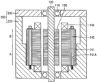
도 2는 본 발명의 일 실시예에 따른 스테이터의 고정구조를 포함한 모터제너레이터(100)의 단면도이다. 도 2에는, 설명의 편의를 위하여 하우징(200) 내의 스테이터수납부와 그 주변만이 도시되어 있지만, 하우징(200)은 스테이터수납부 이외의 여하한의 구성요소를 포함할 수도 있다.2 is a cross-sectional view of the
도 2를 참조하면, 하우징(200)의 스테이터수납부는 케이스(220) 및 커버(230)를 포함한다. 스테이터코어(141)는 철 또는 철합금과 같은 자성재료의 시트들을 서로 적층시켜 형성된다. 스테이터코어(141)는 케이스(220)에 하우징된다. 도 2의 예시에서는, 스테이터코어(141)의 외경이 실질적으로 전체 외주에 걸쳐 축 방향으로 일정하다. 이와는 대조적으로, 케이스(220)의 내주면은 단차부를 가진다. 그러므로, 스테이터코어(141)의 외주면과 케이스(220)의 내주면 간의 클리어런스가 상대적으로 작은 부분(부분 A) 및 상기 클리어런스가 상대적으로 큰 부분(부분 B)이 형성된다.Referring to FIG. 2, the stator accommodating portion of the
도 10 내지 도 13은 도 2에 도시된 스테이터의 고정구조에 의해 제공되는 효과들을 예시한 도면들이다. 여기서, 도 10 및 도 12는 각각 스테이터코어(141)와 케이스(220) 간의 접촉부를 예시한 도면이고, 도 11 및 도 13은 제1 및 제2비교예에 따른 각각의 구조에서의 스테이터코어(141)와 케이스(220) 간의 접촉부를 예시 한 도면들이다.10 to 13 illustrate the effects provided by the fixing structure of the stator shown in FIG. 10 and 12 are views illustrating a contact portion between the
도 10을 참조하면, 본 실시예의 고정구조에서는, 스테이터코어(141)의 축 방향코어와 케이스(220)의 축 방향코어가 서로 약간 변위되어 있는 경우라도, 스테이터코어(141)와 케이스(220)가 서로 스테이터코어(141)의 축 방향으로 일부분에 걸쳐 서로 접촉한다. 즉, 스테이터코어(141)와 케이스(220) 간의 접촉부(C)가 스테이터코어(141)의 축 방향으로 일부분에만 걸쳐 연장된다.Referring to FIG. 10, in the fixing structure of the present embodiment, even when the axial core of the
이와 대조적으로, 제1비교예에 따른 고정구조에서는, 스테이터코어(141)의 축 방향코어와 케이스(220)의 축 방향코어가 서로 도 10의 예시와 유사하게 약간 변위된다면, 스테이터코어(141) 및 케이스(220)는 서로 도 11에 도시된 바와 같이 스테이터코어(141)의 축 방향으로 전체에 걸쳐 접촉한다. 즉, 스테이터코어(141)와 케이스(200) 간의 접촉부(C)가 스테이터코어(141)의 축 방향으로 전체에 걸쳐 연장된다.In contrast, in the fixed structure according to the first comparative example, if the axial core of the
도 12를 참조하면, 본 실시예의 고정구조에서는, 경사각(θ)이 최대각이 될 때까지 스테이터코어(141)가 기울어진다면, 스테이터코어(141)와 케이스(220)가 서로 스테이터코어(141)의 축 방향으로 한 점에서 접촉한다. 다시 말해, 케이스(220)의 대경부의 내경은, 스테이터코어(141)의 경사각(θ)이 최대각이 되는 경우에도, 상기 코어 및 케이스(220)가 서로 접촉하지 않도록 형성된다. 그러므로, 스테이터코어(141)와 케이스(220) 간의 접촉부(C)가 스테이터코어(141)의 축 방향으로 한 점에 제한된다.Referring to FIG. 12, in the fixing structure of the present embodiment, if the
이와는 대조적으로, 제2비교예에 따른 고정구조에서는, 스테이터코어(141)가 도 12의 예시와 유사하게 기울어진다면, 스테이터코어(141) 및 케이스(220)가 서로 도 13에 도시된 바와 같이 스테이터코어(141)의 축 방향으로 소정의 영역에 걸쳐 접촉한다. 즉, 스테이터코어(141)와 케이스(220) 간의 접촉부(C)가 스테이터코어(141)의 축 방향으로 소정의 영역에 걸쳐 연장된다.In contrast, in the fixed structure according to the second comparative example, if the
상기로부터 알 수 있듯이, 본 실시예의 스테이터의 고정구조에서는, 스테이터코어(141)와 케이스(220) 간의 접촉면적이 제1 및 제2비교예에서의 스테이터의 고정구조에서보다 작게 이루어진다. 따라서, 스테이터코어(141)의 진동이 케이스(220)로 전달되기가 쉽지 않다. 또한, 스테이터코어(141)의 외주면과 케이스(220)의 내주면 간의 클리어런스가 상대적으로 작은 부분 A(도 2 참조)에 위치한 케이스(220)의 내경이 일정하게 이루어져, 스테이터코어(141)가 케이스(220) 내에 삽입될 때 스테이터코어(141)의 포지셔닝이 촉진되도록 한다. 그 결과, 로터(130)와 스테이터(140)의 각각의 축 방향코어들의 서로에 대한 변위가 억제된다.As can be seen from the above, in the stator fixing structure of the present embodiment, the contact area between the
따라서, 케이스(220)로의 스테이터코어(141)의 진동의 전달뿐만 아니라 로터(130)와 스테이터(140)의 각각의 축 방향코어들의 서로에 대한 변위가 억제되므로, 모터제너레이터(100)가 구동될 때에 발생되는 잡음이 억제되게 된다.Therefore, since the displacement of the respective axial cores of the
케이스(220)의 대경부의 깊이는 근사적으로 하우징(200)의 개구부의 전체 깊이의 1/2 이하인 것이 바람직하다. 따라서, 케이스(220)의 대경부의 깊이가 제한되므로, 스테이터코어(141)의 경사가 감소될 수 있어, 상기 코어와 케이스(220) 간의 접촉이 억제될 수 있게 된다.The depth of the large diameter portion of the
도 3 내지 도 7은 각각 도 2에 도시된 스테이터의 고정구조의 변형예를 도시 한 도면이다. 도 3을 참조하면, 스테이터코어(141)의 외주면과 케이스(220)의 내주면 간의 클리어런스가 상대적으로 작은 부분 A가 상기 클리어런스가 상대적으로 큰 부분 B에 대하여 커버(230)측에 제공될 수도 있다. 또한, 도 4를 참조하면, 클리어런스가 상대적으로 작은 부분 A와 클리어런스가 상대적으로 큰 부분 B는, 케이스(220)의 내주면 상에 케이스(220)의 내경이 점진적으로 커지는 테이퍼진 부분을 제공하여 형성될 수도 있다. 도 5 내지 도 7을 참조하면, 상술된 부분 A 및 부분 B는 스테이터코어(141)의 축 방향으로 스테이터코어(141)의 외경을 변경하여 제공될 수도 있다. 이러한 경우에도, 스테이터코어(141)의 외주면이 도 5 및 도 6에 도시된 바와 같이 단차부를 가질 수도 있고, 또는 스테이터코어(141)의 외경이 점진적으로 감소하는 테이퍼진 부분이 도 7에 도시된 바와 같이 스테이터코어(141)의 외주면 상에 형성될 수도 있다.3 to 7 are diagrams showing modifications of the stator structure shown in FIG. 2, respectively. Referring to FIG. 3, a portion A having a relatively small clearance between the outer circumferential surface of the
도 8 및 도 9는 각각 본 실시예에 따른 스테이터의 고정구조의 체결부재를 예시한 도면이다. 도 8 및 도 9를 참조하면, 스테이터코어(141)는 축 방향으로 연장되는 구멍(141A)을 포함한다. 체결부재(143)는 구멍(141A) 안에 삽입된다. 체결부재(143)의 일 단부는 케이스(220) 내에 나사결합되어 고정된다. 이에 따라, 체결부재(143)의 축력이 스테이터코어(141)에 전달되고, 스테이터코어(141)가 케이스(220)에 고정된다. 여기서, 체결부재(143)의 타 단부(볼트헤드측의 단부)는 케이스(220)에 의해 지지되지 않는다. 즉, 도 8 및 도 9의 예시들에서, 체결부재(143)는 캔틸레버(cantilever) 방식으로 지지되는데, 즉 케이스(220)에 의해 일 단부에서만 지지된다. 이러한 캔틸레버 구조의 경우에는, 체결부재(143)가 케이스(220)에 고정되는 측에 대향하는 측(즉, 도 8 및 도 9의 상부측)에서 체결부재(143)의 나란한 편차가 더욱 커지기 쉬우므로, 결과적으로는 모터제너레이터(100)가 구동될 때에 발생되는 스테이터코어(141)의 진동이 더욱 커지기 쉽다. 도 8 및 도 9의 예시들에서는, 스테이터코어(141)의 외주면과 케이스(220)의 내주면 간의 클리어런스가 상대적으로 큰 부분 B가 상기 클리어런스가 상대적으로 작은 부분 A에 대하여 커버(230)측(즉, 도 8 및 도 9의 상부측)에 제공된다. 더욱 구체적으로는, 도 8의 예시에서, 스테이터코어(141)의 직경이 실질적으로 축 방향으로 전체에 걸쳐 일정한 한편, 케이스(220)의 내경은 체결부재(143)의 단부(고정부)에 근접한 측에서 더욱 작게 이루어진다. 또한, 도 9의 예시에서는, 케이스(220)의 내경이 실질적으로 축 방향으로 전체에 걸쳐 일정한 한편, 스테이터코어(141)의 외경은 체결부재(143)의 단부(고정부)에 근접한 측에서 더욱 크게 이루어진다. 이러한 방식으로, 도 8 및 도 9의 상부측에 위치한 부분(부분 B)에서는, 스테이터코어(141)의 외주면과 케이스(220)의 내주면 간의 클리어런스가 상대적으로 크게 이루어질 수 있고, 도 8 및 도 9의 하부측에 위치한 부분(부분 A)에서는, 스테이터코어(141)의 외주면과 케이스(220)의 내주면 간의 클리어런스가 상대적으로 작게 이루어질 수 있다.8 and 9 are views illustrating a fastening member of the fixing structure of the stator according to the present embodiment, respectively. 8 and 9, the
도 8 및 도 9에 도시된 구조들은 스테이터코어(141)의 진동이 큰 영역에서 스테이터코어(141)와 케이스(220) 간의 접촉을 억제하는 데 사용될 수 있으므로, 하우징(200)으로의 스테이터코어(141)의 진동의 전달이 더욱 효과적으로 억제될 수 있게 된다. 도 8 및 도 9의 예시들에서는, 케이스(220)의 내주면 또는 스테이터코어(141)의 외주면 상에 단차부가 제공되어, 스테이터코어(141)의 외주면과 케이 스(220)의 내주면 간의 클리어런스를 변화시키게 된다. 대안적으로, 스테이터코어(141)의 외주면과 케이스(220)의 내주면 간의 클리어런스는, 케이스(220)의 내경 또는 스테이터코어(141)의 외경이 점진적으로 변하는 테이퍼진 부분을 제공하여 변경될 수도 있다. 상술된 단차부와 테이퍼진 부분 양자 모두는 스테이터코어(141)의 외주면과 케이스(220)의 내주면 간의 클리어런스를 변경하는 데 사용될 수도 있다.8 and 9 may be used to suppress contact between the
요약하면, 본 실시예에 따른 스테이터의 고정구조는 스테이터코어(141)를 구비한 스테이터(140) 및 스테이터코어(141)를 수납하는 개구부를 구비한 하우징(200)을 포함하고, 하우징(200)은 상기 개구부의 내주면과 스테이터코어(141) 간의 클리어런스가 상대적으로 작고 상기 개구부의 내경이 일정한 "제1부분"에 대응하는 부분 A 및 상기 개구부의 내주면과 스테이터코어(141) 간의 클리어런스가 상대적으로 크고 스테이터코어(141)의 축 방향으로 부분 A에 인접한 "제2부분"에 대응하는 부분 B를 포함한다.In summary, the fixing structure of the stator according to the present embodiment includes a
여기서는, 일 실시형태에 있어서, 부분 A 및 부분 B에서의 각각의 클리어런스들은 도 2 내지 도 4에 도시된 바와 같이 스테이터코어(141)의 축 방향을 따라 하우징(200)의 개구부의 내경을 변경시켜 서로 상이하게 이루어진다.Here, in one embodiment, the respective clearances in the portions A and B may vary the inner diameter of the opening of the
또한, 또다른 실시형태에 있어서는, 부분 A 및 부분 B에서의 각각의 클리어런스들이 도 5 내지 도 7에 도시된 바와 같이 스테이터코어(141)의 축 방향을 따라 스테이터코어(141)의 외경을 변경시켜 서로 상이하게 이루어진다.Further, in another embodiment, the respective clearances in the portions A and B may vary the outer diameter of the
상술된 스테이터의 고정구조에서, 부분 B에서의 개구부의 내주면과 스테이터코어(141) 간의 클리어런스는, 스테이터코어(141)의 경사각(θ)이 최대각인 경우에 도, 하우징(200)의 부분 B와 스테이터코어(141)가 서로 분리되도록 결정된다.In the above-described stator fixing structure, the clearance between the inner circumferential surface of the opening in the portion B and the
더욱이, 상술된 스테이터의 고정구조는 스테이터코어(141)의 축 방향으로 스테이터코어(141) 내에 삽입되고, 일 단부가 하우징(200)에 고정되어 스테이터코어(141)를 하우징(200)에 체결하게 되는 체결부재(143)를 더 포함한다. 하우징(200)의 부분 A는 체결부재(143)가 부분 B에 대하여 하우징(200)에 고정되는 측(즉, 도 8의 하부측)에 위치한다.Furthermore, the above-described stator fixing structure is inserted into the
본 실시예에 따른 스테이터의 고정구조는 스테이터코어(141)의 정밀한 포지셔닝을 촉진하는 데 사용될 수 있는데, 그 이유는 상기 개구부의 내주면과 스테이터코어(141) 간의 클리어런스가 하우징(200)의 부분 A에서 더 작기 때문이다. 또한, 상기 클리어런스는 하우징(200)의 부분 B에서 더 크기 때문에, 상기 개구부의 내주면과 스테이터코어(141) 간의 접촉이 억제되고, 하우징(200)과 스테이터코어(141) 간의 접촉면적이 줄어들게 된다. 따라서, 하우징(200)으로의 스테이터코어(141)의 진동의 전달이 억제될 수 있게 된다. 결과적으로, 모터제너레이터(100)가 구동될 때 발생되는 진동과 잡음이 억제되게 된다.The fixing structure of the stator according to the present embodiment can be used to promote the precise positioning of the
또한, 스테이터코어(141)와 하우징(200) 간의 접촉면적이 작기 때문에, 스테이터코어(141)의 경사각이 큰 경우라도, 하우징(200) 상의 변형 영향이 작으므로, 하우징(200)의 밀봉 능력의 손실이 억제될 수 있게 된다.In addition, since the contact area between the
상술된 실시예들은 모든 실시형태에 있어서 제한적인 것이 아니라 예시적인 것이라는 것을 이해하여야 한다. 본 발명의 범위는 청구범위에 의해 한정되며, 청구범위의 기술적 사상과 범위에 등가인 모든 변경예와 변형예들을 포함하도록 의도 되어 있다.It is to be understood that the above described examples are illustrative rather than limiting in all embodiments. The scope of the invention is defined by the claims, and is intended to include all modifications and variations equivalent to the spirit and scope of the claims.
본 발명은 예컨대 스테이터의 고정구조 및 전동차량에 적용가능하다.The present invention is applicable to, for example, a fixed structure of a stator and an electric vehicle.
Claims (7)
Applications Claiming Priority (2)
| Application Number | Priority Date | Filing Date | Title |
|---|---|---|---|
| JP2006046934A JP4747880B2 (en) | 2006-02-23 | 2006-02-23 | Stator fixing structure and electric vehicle |
| JPJP-P-2006-00046934 | 2006-02-23 |
Publications (2)
| Publication Number | Publication Date |
|---|---|
| KR20080098667A true KR20080098667A (en) | 2008-11-11 |
| KR100998275B1 KR100998275B1 (en) | 2010-12-03 |
Family
ID=38458933
Family Applications (1)
| Application Number | Title | Priority Date | Filing Date |
|---|---|---|---|
| KR1020087023041A Expired - Fee Related KR100998275B1 (en) | 2006-02-23 | 2007-02-13 | Stator fixing device and electric vehicle |
Country Status (7)
| Country | Link |
|---|---|
| US (1) | US7737599B2 (en) |
| EP (1) | EP1988621B1 (en) |
| JP (1) | JP4747880B2 (en) |
| KR (1) | KR100998275B1 (en) |
| CN (1) | CN101390276B (en) |
| AU (1) | AU2007219849B2 (en) |
| WO (1) | WO2007099821A1 (en) |
Cited By (1)
| Publication number | Priority date | Publication date | Assignee | Title |
|---|---|---|---|---|
| KR20210119228A (en) * | 2020-03-24 | 2021-10-05 | 한국생산기술연구원 | Stator-Center Case Assembly Having Rotation Preventing Structure and Motor Having the Same, and Its Manufacturing Method |
Families Citing this family (24)
| Publication number | Priority date | Publication date | Assignee | Title |
|---|---|---|---|---|
| DE102009055409A1 (en) * | 2009-12-16 | 2011-06-22 | Robert Bosch GmbH, 70469 | electric motor |
| WO2011080817A1 (en) | 2009-12-28 | 2011-07-07 | トヨタ自動車株式会社 | Fixing structure for stator core and dynamo-electric machine provided with same |
| JP2012050200A (en) * | 2010-08-25 | 2012-03-08 | Toyota Motor Corp | Split stator core, method of manufacturing the same, and motor including split stator core |
| JP2012061912A (en) * | 2010-09-15 | 2012-03-29 | Aisin Seiki Co Ltd | Drive apparatus for hybrid vehicle and case |
| CN102510140A (en) * | 2011-11-19 | 2012-06-20 | 中电电机股份有限公司 | Compact high-voltage motor stator core structure |
| JP5387929B2 (en) * | 2012-11-20 | 2014-01-15 | 日本精工株式会社 | Rotating electric machine |
| JP6260323B2 (en) * | 2014-02-13 | 2018-01-17 | 株式会社豊田自動織機 | Rotating electric machine |
| JP2016052200A (en) * | 2014-09-01 | 2016-04-11 | スズキ株式会社 | Rotating electric machine |
| JP2016123230A (en) | 2014-12-25 | 2016-07-07 | 日本電産株式会社 | Spindle motor, and disk drive |
| JP6607791B2 (en) * | 2016-01-14 | 2019-11-20 | 三菱重工サーマルシステムズ株式会社 | Motor and electric compressor |
| JP2019140756A (en) * | 2018-02-08 | 2019-08-22 | Ntn株式会社 | In-wheel motor drive device, rotary motor, and method for manufacturing housing |
| JP7281717B2 (en) * | 2018-03-27 | 2023-05-26 | パナソニックIpマネジメント株式会社 | motor |
| FR3080503B1 (en) * | 2018-04-20 | 2020-03-20 | Renault S.A.S | STATOR ASSEMBLY FOR ELECTRIC MACHINE |
| JP7197335B2 (en) | 2018-11-14 | 2022-12-27 | トヨタ自動車株式会社 | vehicle electric motor |
| FR3090231B1 (en) * | 2018-12-14 | 2021-10-29 | Valeo Equip Electr Moteur | ANTI-ROTATION SYSTEM FOR ROTATING ELECTRIC MACHINE STATOR |
| KR20200111328A (en) * | 2019-03-18 | 2020-09-29 | 현대자동차주식회사 | Motor for vehicle |
| JP7231470B2 (en) | 2019-04-19 | 2023-03-01 | トヨタ自動車株式会社 | vehicle electric motor |
| WO2021060102A1 (en) * | 2019-09-23 | 2021-04-01 | 株式会社デンソートリム | Rotary electric machine and stator for rotary electric machine |
| WO2021166171A1 (en) * | 2020-02-20 | 2021-08-26 | 日産自動車株式会社 | Dynamo-electric machine and vehicle-mounting structure for dynamo-electric machine |
| WO2022080030A1 (en) * | 2020-10-15 | 2022-04-21 | 株式会社ミツバ | Motor |
| JP2022081336A (en) * | 2020-11-19 | 2022-05-31 | 日本電産株式会社 | Motor and drive device |
| DE102023203843A1 (en) * | 2023-04-26 | 2024-10-31 | Robert Bosch Gesellschaft mit beschränkter Haftung | Electric Machine |
| DE102023122695A1 (en) * | 2023-08-24 | 2025-02-27 | Valeo Eautomotive Germany Gmbh | Stator device, associated manufacturing method and electric machine for an electrically driven vehicle |
| FR3164856A1 (en) * | 2024-07-16 | 2026-01-23 | Ampere Sas | Electric machine for motor vehicle |
Family Cites Families (19)
| Publication number | Priority date | Publication date | Assignee | Title |
|---|---|---|---|---|
| US4250423A (en) * | 1978-08-25 | 1981-02-10 | Sundstrand Corporation | Generator with stator retention |
| JPS6065389A (en) | 1983-09-21 | 1985-04-15 | Toshiba Corp | Id card processor |
| JPS6065389U (en) * | 1983-10-11 | 1985-05-09 | ダイキン工業株式会社 | Stator fixing structure in compressor |
| JPS61258635A (en) * | 1985-05-08 | 1986-11-17 | Nippon Denso Co Ltd | Ac generator for vehicle |
| US4652782A (en) * | 1986-03-31 | 1987-03-24 | Sundstrand Corporation | Flanged stator assembly for dynamoelectric machine |
| JPS649435A (en) * | 1987-06-30 | 1989-01-12 | Canon Kk | Photographing information display device |
| JPH0615476Y2 (en) | 1987-07-06 | 1994-04-20 | 富士重工業株式会社 | Generator |
| JPH01120750A (en) * | 1987-11-04 | 1989-05-12 | Jeol Ltd | Automatic focal point alignment signal processor |
| JPH09168253A (en) | 1995-12-13 | 1997-06-24 | Sankyo Seiki Mfg Co Ltd | Bearing structure of motor |
| JP3802670B2 (en) | 1997-11-08 | 2006-07-26 | 日本電産株式会社 | Spindle motor |
| JP2000166207A (en) | 1998-11-24 | 2000-06-16 | Shicoh Eng Co Ltd | Brushless fan motor |
| JP2001342954A (en) * | 2000-05-31 | 2001-12-14 | Sanyo Electric Co Ltd | Electric compressor and cooling system using the same |
| JP3963211B2 (en) * | 2001-12-07 | 2007-08-22 | 三菱電機株式会社 | Hermetic compressor |
| JP4121142B2 (en) * | 2002-02-19 | 2008-07-23 | 日本電産株式会社 | motor |
| JP2004015957A (en) | 2002-06-10 | 2004-01-15 | Matsushita Electric Ind Co Ltd | Electric motor |
| JP2005020874A (en) * | 2003-06-25 | 2005-01-20 | Toshiba Tec Corp | motor |
| JP4241321B2 (en) * | 2003-10-28 | 2009-03-18 | トヨタ自動車株式会社 | Rotating electric machine stator |
| JP4572699B2 (en) | 2005-02-23 | 2010-11-04 | トヨタ自動車株式会社 | Fixed structure of rotating electric machine |
| JP2005229798A (en) * | 2005-02-24 | 2005-08-25 | Sanyo Electric Co Ltd | Refrigeration device |
-
2006
- 2006-02-23 JP JP2006046934A patent/JP4747880B2/en not_active Expired - Lifetime
-
2007
- 2007-02-13 US US12/087,994 patent/US7737599B2/en active Active
- 2007-02-13 CN CN2007800062580A patent/CN101390276B/en not_active Expired - Fee Related
- 2007-02-13 EP EP07714618.1A patent/EP1988621B1/en not_active Ceased
- 2007-02-13 AU AU2007219849A patent/AU2007219849B2/en not_active Ceased
- 2007-02-13 KR KR1020087023041A patent/KR100998275B1/en not_active Expired - Fee Related
- 2007-02-13 WO PCT/JP2007/053118 patent/WO2007099821A1/en not_active Ceased
Cited By (1)
| Publication number | Priority date | Publication date | Assignee | Title |
|---|---|---|---|---|
| KR20210119228A (en) * | 2020-03-24 | 2021-10-05 | 한국생산기술연구원 | Stator-Center Case Assembly Having Rotation Preventing Structure and Motor Having the Same, and Its Manufacturing Method |
Also Published As
| Publication number | Publication date |
|---|---|
| EP1988621A1 (en) | 2008-11-05 |
| KR100998275B1 (en) | 2010-12-03 |
| US20090021104A1 (en) | 2009-01-22 |
| EP1988621B1 (en) | 2020-03-25 |
| JP4747880B2 (en) | 2011-08-17 |
| US7737599B2 (en) | 2010-06-15 |
| CN101390276A (en) | 2009-03-18 |
| EP1988621A4 (en) | 2016-12-21 |
| CN101390276B (en) | 2012-07-04 |
| AU2007219849A1 (en) | 2007-09-07 |
| JP2007228725A (en) | 2007-09-06 |
| WO2007099821A1 (en) | 2007-09-07 |
| AU2007219849B2 (en) | 2011-02-10 |
Similar Documents
| Publication | Publication Date | Title |
|---|---|---|
| KR100998275B1 (en) | Stator fixing device and electric vehicle | |
| US6700268B2 (en) | Rotational electric machine and a vehicle loaded therewith | |
| JP4842670B2 (en) | Rotor and electric vehicle | |
| Freitag et al. | High-performance and highly efficient electric wheel hub drive in automotive design | |
| US9379589B2 (en) | Stator | |
| JP4811114B2 (en) | Stator fixing structure and vehicle | |
| JP2008289244A (en) | Cooling structure of rotating electric machine | |
| CN116345766A (en) | Rotors, electrically excited motors, powertrains and vehicles | |
| JP4661614B2 (en) | Cooling pipe fixing structure and electric vehicle | |
| KR20220026282A (en) | In-wheel Motor For Electric Vehicle | |
| JP2012125014A (en) | On-vehicle rotary electric machine and electric vehicle | |
| JP4685661B2 (en) | Rotor, method for manufacturing the same, and electric vehicle | |
| JP2007336714A (en) | Resolver sensor fixed structure | |
| JP5141233B2 (en) | Drive device | |
| JP4775020B2 (en) | Stator fixing structure and electric vehicle | |
| JP5109260B2 (en) | Rotor, method for manufacturing the same, and electric vehicle | |
| JP4962280B2 (en) | Rotating electric machine | |
| KR20160051580A (en) | Permanent magnet motor | |
| JP2007221854A (en) | Stator fixing structure and electric vehicle | |
| CN218498941U (en) | Casing, stator assembly, motor and vehicle | |
| US20240162764A1 (en) | Rotary electric machine | |
| KR20260009894A (en) | A set of powertrain elements | |
| JP2008301571A (en) | Rotating electric machine and method of manufacturing rotating electric machine | |
| JP2006345601A (en) | Rotating electric machine | |
| JP2025176429A (en) | motor |
Legal Events
| Date | Code | Title | Description |
|---|---|---|---|
| A201 | Request for examination | ||
| PA0105 | International application |
St.27 status event code: A-0-1-A10-A15-nap-PA0105 |
|
| PA0201 | Request for examination |
St.27 status event code: A-1-2-D10-D11-exm-PA0201 |
|
| PG1501 | Laying open of application |
St.27 status event code: A-1-1-Q10-Q12-nap-PG1501 |
|
| R18-X000 | Changes to party contact information recorded |
St.27 status event code: A-3-3-R10-R18-oth-X000 |
|
| E902 | Notification of reason for refusal | ||
| PE0902 | Notice of grounds for rejection |
St.27 status event code: A-1-2-D10-D21-exm-PE0902 |
|
| P11-X000 | Amendment of application requested |
St.27 status event code: A-2-2-P10-P11-nap-X000 |
|
| P13-X000 | Application amended |
St.27 status event code: A-2-2-P10-P13-nap-X000 |
|
| E701 | Decision to grant or registration of patent right | ||
| PE0701 | Decision of registration |
St.27 status event code: A-1-2-D10-D22-exm-PE0701 |
|
| GRNT | Written decision to grant | ||
| PR0701 | Registration of establishment |
St.27 status event code: A-2-4-F10-F11-exm-PR0701 |
|
| PR1002 | Payment of registration fee |
St.27 status event code: A-2-2-U10-U12-oth-PR1002 Fee payment year number: 1 |
|
| PG1601 | Publication of registration |
St.27 status event code: A-4-4-Q10-Q13-nap-PG1601 |
|
| FPAY | Annual fee payment |
Payment date: 20131031 Year of fee payment: 4 |
|
| PR1001 | Payment of annual fee |
St.27 status event code: A-4-4-U10-U11-oth-PR1001 Fee payment year number: 4 |
|
| FPAY | Annual fee payment |
Payment date: 20141103 Year of fee payment: 5 |
|
| PR1001 | Payment of annual fee |
St.27 status event code: A-4-4-U10-U11-oth-PR1001 Fee payment year number: 5 |
|
| LAPS | Lapse due to unpaid annual fee | ||
| PC1903 | Unpaid annual fee |
St.27 status event code: A-4-4-U10-U13-oth-PC1903 Not in force date: 20151130 Payment event data comment text: Termination Category : DEFAULT_OF_REGISTRATION_FEE |
|
| P22-X000 | Classification modified |
St.27 status event code: A-4-4-P10-P22-nap-X000 |
|
| PC1903 | Unpaid annual fee |
St.27 status event code: N-4-6-H10-H13-oth-PC1903 Ip right cessation event data comment text: Termination Category : DEFAULT_OF_REGISTRATION_FEE Not in force date: 20151130 |