EP1988621B1 - Securing structure of stator and electric vehicle - Google Patents
Securing structure of stator and electric vehicle Download PDFInfo
- Publication number
- EP1988621B1 EP1988621B1 EP07714618.1A EP07714618A EP1988621B1 EP 1988621 B1 EP1988621 B1 EP 1988621B1 EP 07714618 A EP07714618 A EP 07714618A EP 1988621 B1 EP1988621 B1 EP 1988621B1
- Authority
- EP
- European Patent Office
- Prior art keywords
- stator core
- stator
- circumferential surface
- securing structure
- housing
- Prior art date
- Legal status (The legal status is an assumption and is not a legal conclusion. Google has not performed a legal analysis and makes no representation as to the accuracy of the status listed.)
- Expired - Fee Related
Links
- 238000010586 diagram Methods 0.000 description 13
- 230000004048 modification Effects 0.000 description 7
- 238000012986 modification Methods 0.000 description 7
- 230000000052 comparative effect Effects 0.000 description 6
- XEEYBQQBJWHFJM-UHFFFAOYSA-N Iron Chemical group [Fe] XEEYBQQBJWHFJM-UHFFFAOYSA-N 0.000 description 5
- 230000005540 biological transmission Effects 0.000 description 5
- 238000006073 displacement reaction Methods 0.000 description 2
- 238000003475 lamination Methods 0.000 description 2
- 229910000640 Fe alloy Inorganic materials 0.000 description 1
- 230000007423 decrease Effects 0.000 description 1
- 230000003247 decreasing effect Effects 0.000 description 1
- 230000001419 dependent effect Effects 0.000 description 1
- 238000011161 development Methods 0.000 description 1
- 230000018109 developmental process Effects 0.000 description 1
- 230000000694 effects Effects 0.000 description 1
- 239000000446 fuel Substances 0.000 description 1
- 229910052742 iron Inorganic materials 0.000 description 1
- 239000000696 magnetic material Substances 0.000 description 1
- 238000000034 method Methods 0.000 description 1
- 238000005057 refrigeration Methods 0.000 description 1
- 230000001172 regenerating effect Effects 0.000 description 1
- 238000007789 sealing Methods 0.000 description 1
Images


Classifications
-
- H—ELECTRICITY
- H02—GENERATION; CONVERSION OR DISTRIBUTION OF ELECTRIC POWER
- H02K—DYNAMO-ELECTRIC MACHINES
- H02K1/00—Details of the magnetic circuit
- H02K1/06—Details of the magnetic circuit characterised by the shape, form or construction
- H02K1/12—Stationary parts of the magnetic circuit
- H02K1/18—Means for mounting or fastening magnetic stationary parts on to, or to, the stator structures
- H02K1/185—Means for mounting or fastening magnetic stationary parts on to, or to, the stator structures to outer stators
-
- H—ELECTRICITY
- H02—GENERATION; CONVERSION OR DISTRIBUTION OF ELECTRIC POWER
- H02K—DYNAMO-ELECTRIC MACHINES
- H02K1/00—Details of the magnetic circuit
- H02K1/06—Details of the magnetic circuit characterised by the shape, form or construction
- H02K1/12—Stationary parts of the magnetic circuit
-
- H—ELECTRICITY
- H02—GENERATION; CONVERSION OR DISTRIBUTION OF ELECTRIC POWER
- H02K—DYNAMO-ELECTRIC MACHINES
- H02K5/00—Casings; Enclosures; Supports
- H02K5/24—Casings; Enclosures; Supports specially adapted for suppression or reduction of noise or vibrations
-
- Y—GENERAL TAGGING OF NEW TECHNOLOGICAL DEVELOPMENTS; GENERAL TAGGING OF CROSS-SECTIONAL TECHNOLOGIES SPANNING OVER SEVERAL SECTIONS OF THE IPC; TECHNICAL SUBJECTS COVERED BY FORMER USPC CROSS-REFERENCE ART COLLECTIONS [XRACs] AND DIGESTS
- Y02—TECHNOLOGIES OR APPLICATIONS FOR MITIGATION OR ADAPTATION AGAINST CLIMATE CHANGE
- Y02T—CLIMATE CHANGE MITIGATION TECHNOLOGIES RELATED TO TRANSPORTATION
- Y02T10/00—Road transport of goods or passengers
- Y02T10/60—Other road transportation technologies with climate change mitigation effect
- Y02T10/64—Electric machine technologies in electromobility
Definitions
- the present invention relates to a securing structure with a stator and an electric vehicle, and particularly to a securing structure with a stator that suppresses vibration and noise caused when a rotating electric machine is driven, as well as an electric vehicle including the securing structure.
- a rotating electric machine including a stator has conventionally been known.
- document JP 2004-15957 A discloses an electric motor (rotating electric machine) in which a stator having a stator core is press-fit in a housing (case).
- document JP 2000-166207 A discloses a brushless fan motor having a rubber vibration isolator provided at a portion of contact between a case containing a stator and another casing.
- document JP 9-168253 A discloses a bearing structure for a motor with the intention of suppressing vibration and mechanical noise.
- a paper of issue number 16748 in Toyota Technical Publications published on April 28, 2005 discloses a technique regarding a securing structure for an IPM (Interior Permanent Magnet) motor, for reducing vibration and noise by allowing a stator core and a high stiffness portion of a motor case to selectively abut on each other.
- IPM Interior Permanent Magnet
- the amount of eccentricity between the stator and the rotor is likely to be increased. As a result, imbalance in the electromagnetic attraction force occurs and accordingly vibration and noise increase. Further, if the amount of eccentricity between the stator and the rotor is particularly large, there is the concern that interference between the stator and the rotor might occur.
- Document US 4 652 782 A discloses a flanged stator assembly for a dynamoelectric machine.
- a stator assembly is mounted directly to a mounting face of a housing surrounding a rotor projecting from the housing beyond the mounting face in a cantilevered orientation.
- the stator assembly includes a plurality of laminations bonded together in a stacked array for circumferentially surrounding the rotor. A given number of the laminations at one end of the stator assembly are radially enlarged to define a circumferential mounting flange.
- the flange is secured directly to the mounting face of the housing and adjustable relative thereto.
- document JP 2005 229798 A discloses a refrigeration device.
- a contact area of a stator and a shell part of an electric compressor is reduced.
- An electric element (motor) is composed of the stator, which is abutted on and fixed to the inner wall of a sealed container and has a stator iron core, and a rotor, which has a magnetic body, is mounted on a rotating shaft, and freely rotatably supported inside the stator. If the dimension in the rotating shaft direction at a contact part of the stator iron core with the sealed container is set to H and the dimension in the rotating shaft direction of the stator iron core is set to Ho, the relation H ⁇ Ho is established.
- An object of the present invention is to provide a securing structure with a stator that suppresses vibration and noise as well as an electric vehicle including the securing structure.
- a securing structure with a stator includes the stator having a stator core, and a housing having an opening portion containing the stator core.
- the housing includes a first portion where a clearance between an inner circumferential surface of the opening portion and the stator core is relatively smaller and an inner diameter of the opening portion is constant, and a second portion where the clearance between the inner circumferential surface of the opening portion and the stator core is relatively larger, the second portion being located adjacent to the first portion in an axial direction of the stator core.
- the clearance between the inner circumferential surface of the opening portion and the stator core is smaller in the first portion of the housing, so that precise positioning of the stator core is facilitated. Further, the clearance is larger in the second portion of the housing, so that contact between the inner circumferential surface of the opening portion and the stator core is suppressed and the area of contact between the housing and the stator core is reduced.
- transmission of vibration of the stator core to the housing can be suppressed. Consequently, vibration and noise caused when the rotating electric machine is driven are suppressed.
- respective clearances in the first portion and the second portion, between the inner circumferential surface of the opening portion and the stator core are made different from each other by varying the inner diameter of the opening portion of the housing along the axial direction of the stator core.
- respective clearances in the first portion and the second portion, between the inner circumferential surface of the opening portion and the stator core are made different from each other by varying an outer diameter of the stator core along the axial direction of the stator core.
- the second portion has a depth of at most a half of a whole depth of the opening portion.
- the depth of the second portion where the inner diameter of the opening portion is relatively larger is restricted, and accordingly inclination of the stator core can be reduced.
- the clearance between the inner circumferential surface of the opening portion and the stator core in the second portion is determined such that the second portion of the housing and the stator core are apart from each other even in a case where an angle of inclination of the stator core is a maximum angle.
- the securing structure with the stator further includes a fastening member inserted into the stator core in the axial direction of the stator core, and having one end secured to the housing to fasten the stator core to the housing.
- the first portion is located on a side where the fastening member is secured to the housing relative to the second portion.
- An electric vehicle of the present invention includes the securing structure with the stator as described above.
- the electric vehicle having a significantly quiet interior can be obtained.
- vibration and noise caused when the rotating electric machine is driven can be suppressed, as described above.
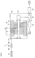
- Fig. 1 is a diagram schematically showing a configuration of a drive unit to which a securing structure with a stator according to an embodiment of the present invention is applied.
- drive unit 1 refers to a drive unit mounted on a hybrid vehicle that is "electric vehicle", and is configured to include a motor generator 100, a housing 200, a reduction mechanism 300, a differential mechanism 400, and a drive shaft receiving portion 500.
- Motor generator 100 is a rotating electric machine having the function of an electric motor or electric generator, and includes a rotational shaft 120 rotatably attached to housing 200 via a bearing 110, a rotor 130 attached to rotational shaft 120, and a stator 140.
- Stator 140 includes a stator core 141, and a coil 142 is wound around stator core 141.
- Coil 142 is electrically connected to a feed cable 600A via a terminal block 210 provided to housing 200.
- Feed cable 600A has another end connected to a PCU 600.
- PCU 600 is electrically connected to a battery 700 via a feed cable 700A. Accordingly, battery 700 and coil 142 are electrically connected.
- the motive energy that is output from motor generator 100 is transmitted from reduction mechanism 300 through differential mechanism 400 to drive shaft receiving portion 500.
- the drive force transmitted to drive shaft receiving portion 500 is transmitted in the form of a rotational force through a driveshaft (not shown) to wheels (not shown) to cause the vehicle to run.
- motor generator 100 drives motor generator 100 via drive shaft receiving portion 500, differential mechanism 400 and reduction mechanism 300.
- motor generator 100 operates as an electric generator.
- the electric power generated by motor generator 100 is stored in battery 700 through an inverter in PCU 600.
- Feed cables 600A, 700A are each a three-phase cable formed of a U phase cable, a V phase cable and a W phase cable.
- Coil 142 is formed of a U phase coil, a V phase coil and a W phase coil, and respective terminals of these three coils are connected to feed cables 600A, 700A that are each the three-phase cable.
- motor generator 100 is not limited to a hybrid vehicle (HV) and may be mounted on other "electric vehicles” (such as fuel cell vehicle and electric vehicle for example).
- the hybrid vehicle has, for example, a mode of stopping the engine while traveling (such as an EV travel mode in which the vehicle is caused to travel by an electric motor supplied with electric power from a power storage mechanism while the vehicle speed is low, and a regenerative mode in which the kinetic energy of the vehicle is converted into electrical energy to be stored in a power storage mechanism while the vehicle is decelerated).
- a mode of stopping the engine while traveling such as an EV travel mode in which the vehicle is caused to travel by an electric motor supplied with electric power from a power storage mechanism while the vehicle speed is low, and a regenerative mode in which the kinetic energy of the vehicle is converted into electrical energy to be stored in a power storage mechanism while the vehicle is decelerated.
- the background noise is low and thus gear noise and motor noise are relatively more likely to be heard. Therefore, it is important to suppress the noise while the motor generator 100 is driven.
- motor generator 100 to be mounted on a vehicle is under restrictions on adoption of noise control measures for a transmission system and a resonance system, because of limitations of
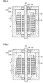
- Fig. 2 is a cross section of motor generator 100 including a securing structure with a stator according to an embodiment of the present invention.
- housing 200 may include any component other than the stator-containing portion.
- the stator-containing portion of housing 200 includes a case 220 and a cover 230.
- Stator core 141 is formed by stacking sheets of a magnetic material such as iron or iron alloy on each other. Stator core 141 is housed in case 220.
- the outer diameter of stator core 141 is substantially constant in the axial direction over the whole outer periphery.
- the inner circumferential surface of case 220 has a stepped portion. Therefore, a portion where the clearance between the outer circumferential surface of stator core 141 and the inner circumferential surface of case 220 is relatively smaller (portion A) and a portion where this clearance is relatively larger (portion B) are formed.
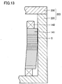
- Figs. 10 to 13 are diagrams illustrating effects provided by the securing structure with the stator shown in Fig. 2 .
- Figs. 10 and 12 are each a diagram illustrating a portion of contact between stator core 141 and case 220
- Figs. 11 and 13 are diagrams illustrating a portion of contact between stator core 141 and case 220 in respective structures according to first and second comparative examples.
- stator core 141 and case 220 contact each other over a part in the axial direction of stator core 141. Namely, a contact portion C between stator core 141 and case 220 extends over only a part in the axial direction of stator core 141.
- stator core 141 and case 220 contact each other over the whole in the axial direction of stator core 141 as shown in Fig. 11 .
- contact portion C between stator core 141 and case 200 extends over the whole in the axial direction of stator core 141.
- stator core 141 and case 220 contact each other at one point in the axial direction of stator core 141.
- the inner diameter of the larger-diameter portion of case 220 is defined such that the core and case 220 do not contact each other even in the case where the angle of inclination ( ⁇ ) of stator core 141 becomes a maximum angle. Therefore, contact portion C between stator core 141 and case 220 is limited to one point in the axial direction of stator core 141.
- stator core 141 is inclined similarly to the example in Fig. 12 , stator core 141 and case 220 contact each other over a certain region in the axial direction of stator core 141 as shown in Fig. 13 .
- contact portion C between stator core 141 and case 220 extends over a certain region in the axial direction of stator core 141.
- the area of contact between stator core 141 and case 220 is made smaller than that in the securing structures for the stator in the first and second comparative examples.
- vibration of stator core 141 is less likely to be transmitted to case 220.
- the inner diameter of case 220 located in portion A (see Fig. 2 ) where the clearance between the outer circumferential surface of stator core 141 and the inner circumferential surface of case 220 is relatively small is made constant, so that positioning of stator core 141 when stator core 141 is inserted into case 220 is facilitated. As a result, displacement of respective axial cores of rotor 130 and stator 140 from each other is suppressed.
- stator core 141 to case 220 The transmission of vibration of stator core 141 to case 220 as well as the displacement of respective axial cores of rotor 130 and stator 140 from each other are thus suppressed, so that noise caused when motor generator 100 is driven is suppressed.
- the depth of the larger diameter portion of case 220 is approximately a half or less of the depth of the whole of the opening portion of housing 200.
- the depth of the larger diameter portion of case 220 is thus limited, so that inclination of stator core 141 can be reduced and contact between the core and case 220 can be suppressed.
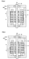
- Figs. 3 to 7 are each a diagram showing a modification of the securing structure with the stator shown in Fig. 2 .
- portion A where the clearance between the outer circumferential surface of stator core 141 and the inner circumferential surface of case 220 is relatively small may be provided on cover 230 side with respect to portion B where the clearance is relatively large.
- portion A where the clearance is relatively small and portion B where the clearance is relatively large may be formed by providing a tapered portion where the inner diameter of case 220 becomes gradually larger, on the inner circumferential surface of case 220. Referring to Figs.
- portion A and portion B as described above may be provided by varying the outer diameter of stator core 141 in the axial direction of stator core 141.
- the outer circumferential surface of stator core 141 may have a stepped portion as shown in Figs. 5 and 6 , or a tapered portion where the outer diameter of stator core 141 gradually decreases may be formed on the outer circumferential surface of stator core 141 as shown in Fig. 7 .
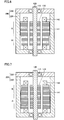
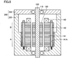
- Figs. 8 and 9 are each a diagram illustrating a fastening member in the securing structure with the stator according to the present embodiment.
- stator core 141 includes a hole 141A extending in the axial direction.
- a fastening member 143 is inserted into hole 141A.
- An end of fastening member 143 is screwed into and secured to case 220. Accordingly, the axial force of fastening member 143 is transmitted to stator core 141 and stator core 141 is secured to case 220.
- the other end (the end on the bolt head side) of fastening member 143 is not supported by case 220. Namely, in the examples in Figs.
- fastening member 143 is supported in cantilever manner, namely supported at only one end by case 220.
- the side-to-side deviation of fastening member 143 tends to become larger on the side (namely the upper side in Figs. 8 and 9 ) opposite to the side where fastening member 143 is secured to case 220, and consequently vibration of stator core 141 caused when motor generator 100 is driven is likely to become larger.
- portion B where the clearance between the outer circumferential surface of stator core 141 and the inner circumferential surface of case 220 is relatively large is provided on cover 230 side (namely the upper side in Figs.
- the diameter of stator core 141 is substantially constant over the whole in the axial direction, while the inner diameter of case 220 is made smaller on the side closer to the end (secured portion) of fastening member 143.
- the outer diameter of stator core 141 is made larger on the side closer to the end (secured portion) of fastening member 143. In this way, in the portion located on the upper side in Figs.
- the clearance between the outer circumferential surface of stator core 141 and the inner circumferential surface of case 220 can be made relatively larger and, in the portion located on the lower side in Figs. 8 and 9 (portion A), the clearance between the outer circumferential surface of stator core 141 and the inner circumferential surface of case 220 can be made relatively smaller.
- a stepped portion is provided on the inner circumferential surface of case 220 or the outer circumferential surface of stator core 141 to vary the clearance between the outer circumferential surface of stator core 141 and the inner circumferential surface of case 220.
- the clearance between the outer circumferential surface of stator core 141 and the inner circumferential surface of case 220 may be varied by providing the tapered portion where the inner diameter of case 220 or the outer diameter of stator core 141 is gradually varied. Both of the above-described stepped portion and the tapered portion may be used to vary the clearance between the outer circumferential surface of stator core 141 and the inner circumferential surface of case 220.
- the securing structure with the stator includes stator 140 having stator core 141 and housing 200 having an opening portion containing stator core 141, and housing 200 includes portion A corresponding to "first portion” where the clearance between the inner circumferential surface of the opening portion and stator core 141 is relatively smaller and the inner diameter of the opening portion is constant, and portion B corresponding to "second portion” adjacent to portion A in the axial direction of stator core 141 where the clearance between the inner circumferential surface of the opening portion and stator core 141 is relatively larger.
- respective clearances in portion A and portion B are made different from each other by varying the inner diameter of the opening portion of housing 200 along the axial direction of stator core 141 as shown in Figs. 2 to 4 .
- respective clearances in portion A and portion B are made different from each other by varying the outer diameter of stator core 141 along the axial direction of stator core 141 as shown in Figs. 5 to 7 .
- the clearance between the inner circumferential surface of the opening portion and stator core 141 in portion B is determined such that portion B of housing 200 and stator core 141 is separated from each other even in the case where the angle of inclination ( ⁇ ) of stator core 141 is a maximum angle.
- the securing structure with the stator as described above further includes fastening member 143 inserted into stator core 141 in the axial direction of stator core 141 and having one end secured to housing 200 to fasten stator core 141 to housing 200.
- Portion A of housing 200 is located on the side where fastening member 143 is secured to housing 200 (namely the lower side in Fig. 8 ) relative to portion B.
- the securing structure with the stator according to the present embodiment can be used to facilitate precise positioning of stator core 141, since the clearance between the inner circumferential surface of the opening portion and stator core 141 is smaller in portion A of housing 200. Further, since the clearance is larger in portion B of housing 200, contact between the inner circumferential surface of the opening portion and stator core 141 is suppressed, and the area of contact between hosing 200 and stator core 141 is reduced. Thus, transmission of vibration of stator core 141 to housing 200 can be suppressed. Consequently, the vibration and noise caused when motor generator 100 is driven are suppressed.
- stator core 141 and housing 200 are small, even if the angle of inclination of stator core 141 is large, the influence of the deformation on housing 200 is small so that loss of the sealing ability of housing 200 can be suppressed.
- the present invention is applicable for example to a securing structure with a stator and an electric vehicle.
Description
- The present invention relates to a securing structure with a stator and an electric vehicle, and particularly to a securing structure with a stator that suppresses vibration and noise caused when a rotating electric machine is driven, as well as an electric vehicle including the securing structure.
- A rotating electric machine including a stator has conventionally been known.
- For example, document
JP 2004-15957 A - Further, document
JP 2000-166207 A - Furthermore, document
JP 9-168253 A - Moreover, a paper of issue number 16748 in Toyota Technical Publications published on April 28, 2005 discloses a technique regarding a securing structure for an IPM (Interior Permanent Magnet) motor, for reducing vibration and noise by allowing a stator core and a high stiffness portion of a motor case to selectively abut on each other.
- In the case where a stator is fit in a case so that the position where the stator is attached is determined, vibration of the stator caused when a rotating electric machine is driven is likely to be transmitted to the case.
- Here, if the tolerance in fitting the stator is increased, the amount of eccentricity between the stator and the rotor is likely to be increased. As a result, imbalance in the electromagnetic attraction force occurs and accordingly vibration and noise increase. Further, if the amount of eccentricity between the stator and the rotor is particularly large, there is the concern that interference between the stator and the rotor might occur.
- In contrast, if the tolerance in fitting the stator is decreased, the working efficiency in inserting the stator into the case is deteriorated. Further, the area of contact between the case and the stator increases, and accordingly vibration of the stator without being damped is likely to be transmitted to the case.
- Document
US 4 652 782 A discloses a flanged stator assembly for a dynamoelectric machine. In the dynamoelectric machine, a stator assembly is mounted directly to a mounting face of a housing surrounding a rotor projecting from the housing beyond the mounting face in a cantilevered orientation. The stator assembly includes a plurality of laminations bonded together in a stacked array for circumferentially surrounding the rotor. A given number of the laminations at one end of the stator assembly are radially enlarged to define a circumferential mounting flange. The flange is secured directly to the mounting face of the housing and adjustable relative thereto. - Further relevant prior art is disclosed in document
JP S64 9435 U - Moreover, document
JP 2005 229798 A - An object of the present invention is to provide a securing structure with a stator that suppresses vibration and noise as well as an electric vehicle including the securing structure.
- This object is achieved by a securing structure with a stator according to claim 1. Advantageous further developments are as set forth in the dependent claims. Furthermore, an electric vehicle according to claim 10 is provided.
- A securing structure with a stator according to one aspect includes the stator having a stator core, and a housing having an opening portion containing the stator core. The housing includes a first portion where a clearance between an inner circumferential surface of the opening portion and the stator core is relatively smaller and an inner diameter of the opening portion is constant, and a second portion where the clearance between the inner circumferential surface of the opening portion and the stator core is relatively larger, the second portion being located adjacent to the first portion in an axial direction of the stator core.
- In the above-described structure, the clearance between the inner circumferential surface of the opening portion and the stator core is smaller in the first portion of the housing, so that precise positioning of the stator core is facilitated. Further, the clearance is larger in the second portion of the housing, so that contact between the inner circumferential surface of the opening portion and the stator core is suppressed and the area of contact between the housing and the stator core is reduced. Thus, transmission of vibration of the stator core to the housing can be suppressed. Consequently, vibration and noise caused when the rotating electric machine is driven are suppressed.
- In a further aspect, in the securing structure with the stator, respective clearances in the first portion and the second portion, between the inner circumferential surface of the opening portion and the stator core are made different from each other by varying the inner diameter of the opening portion of the housing along the axial direction of the stator core.
- In another aspect, in the securing structure with the stator, respective clearances in the first portion and the second portion, between the inner circumferential surface of the opening portion and the stator core are made different from each other by varying an outer diameter of the stator core along the axial direction of the stator core.
- In the securing structure with the stator, preferably the second portion has a depth of at most a half of a whole depth of the opening portion.
- The depth of the second portion where the inner diameter of the opening portion is relatively larger is restricted, and accordingly inclination of the stator core can be reduced.
- In the securing structure with the stator, preferably the clearance between the inner circumferential surface of the opening portion and the stator core in the second portion is determined such that the second portion of the housing and the stator core are apart from each other even in a case where an angle of inclination of the stator core is a maximum angle.
- The securing structure with the stator further includes a fastening member inserted into the stator core in the axial direction of the stator core, and having one end secured to the housing to fasten the stator core to the housing. The first portion is located on a side where the fastening member is secured to the housing relative to the second portion.
- Thus, contact between the stator core and the housing in a portion where vibration of the stator core is large can be suppressed. Consequently, vibration and noise caused when the rotating electric machine is driven can be suppressed more effectively.
- An electric vehicle of the present invention includes the securing structure with the stator as described above. Thus, the electric vehicle having a significantly quiet interior can be obtained.
- According to the present invention, vibration and noise caused when the rotating electric machine is driven can be suppressed, as described above.
-
-
Fig. 1 is a diagram schematically showing a configuration of a drive unit to which a securing structure with a stator according to an embodiment of the present invention is applied. -
Fig. 2 is a cross section of a rotating electric machine including a securing structure with a stator according to an embodiment of the present invention. -
Fig. 3 is a cross section of a rotating electric machine including a modification of the securing structure with the stator according to an embodiment of the present invention. -
Fig. 4 is a cross section of a rotating electric machine including another modification of the securing structure with the stator according to an embodiment of the present invention. -
Fig. 5 is a cross section of a rotating electric machine including still another modification of the securing structure with the stator according to an embodiment of the present invention. -
Fig. 6 is a cross section of a rotating electric machine including a further modification of the securing structure with the stator according to an embodiment of the present invention. -
Fig. 7 is a cross section of a rotating electric machine including a further modification of the securing structure with the stator according to an embodiment of the present invention. -
Fig. 8 is a (first) diagram illustrating a fastening member in a securing structure with a stator according to an embodiment of the present invention. -
Fig. 9 is a (second) diagram illustrating a fastening member in a securing structure with a stator according to an embodiment of the present invention. -
Fig. 10 is a (first) diagram illustrating a portion of contact between a stator core and a housing in a securing structure with a stator according to an embodiment of the present invention. -
Fig. 11 is a diagram illustrating a portion of contact between a stator core and a housing in a securing structure with a stator according to a first comparative example. -
Fig. 12 is a (second) diagram illustrating a portion of contact between a stator core and a housing in a securing structure with a stator according to an embodiment of the present invention. -
Fig. 13 is a diagram illustrating a portion of contact between a stator core and a housing in securing structure with a stator according to a second comparative example. - In the following, embodiments of a securing structure with a stator and an electric vehicle based on the present invention will be described. Here, like or corresponding components are denoted by like reference characters and a description thereof may not be repeated in some cases.
-
Fig. 1 is a diagram schematically showing a configuration of a drive unit to which a securing structure with a stator according to an embodiment of the present invention is applied. In the example shown inFig. 1 , drive unit 1 refers to a drive unit mounted on a hybrid vehicle that is "electric vehicle", and is configured to include amotor generator 100, ahousing 200, areduction mechanism 300, adifferential mechanism 400, and a driveshaft receiving portion 500. -
Motor generator 100 is a rotating electric machine having the function of an electric motor or electric generator, and includes arotational shaft 120 rotatably attached tohousing 200 via abearing 110, arotor 130 attached torotational shaft 120, and astator 140.Stator 140 includes astator core 141, and acoil 142 is wound aroundstator core 141.Coil 142 is electrically connected to afeed cable 600A via aterminal block 210 provided tohousing 200.Feed cable 600A has another end connected to aPCU 600.PCU 600 is electrically connected to abattery 700 via afeed cable 700A. Accordingly,battery 700 andcoil 142 are electrically connected. - The motive energy that is output from
motor generator 100 is transmitted fromreduction mechanism 300 throughdifferential mechanism 400 to driveshaft receiving portion 500. The drive force transmitted to driveshaft receiving portion 500 is transmitted in the form of a rotational force through a driveshaft (not shown) to wheels (not shown) to cause the vehicle to run. - In contrast, when the hybrid vehicle is regeneratively braked, the wheels are rotated by an inertial force of the vehicle body. The rotational force from the wheels drives
motor generator 100 via driveshaft receiving portion 500,differential mechanism 400 andreduction mechanism 300. At this time,motor generator 100 operates as an electric generator. The electric power generated bymotor generator 100 is stored inbattery 700 through an inverter inPCU 600. -
Feed cables Coil 142 is formed of a U phase coil, a V phase coil and a W phase coil, and respective terminals of these three coils are connected to feedcables - The use of
motor generator 100 is not limited to a hybrid vehicle (HV) and may be mounted on other "electric vehicles" (such as fuel cell vehicle and electric vehicle for example). - The hybrid vehicle has, for example, a mode of stopping the engine while traveling (such as an EV travel mode in which the vehicle is caused to travel by an electric motor supplied with electric power from a power storage mechanism while the vehicle speed is low, and a regenerative mode in which the kinetic energy of the vehicle is converted into electrical energy to be stored in a power storage mechanism while the vehicle is decelerated). In this mode, the background noise is low and thus gear noise and motor noise are relatively more likely to be heard. Therefore, it is important to suppress the noise while the
motor generator 100 is driven. Further, in some cases,motor generator 100 to be mounted on a vehicle is under restrictions on adoption of noise control measures for a transmission system and a resonance system, because of limitations of space and weight. It is thus important to suppress noise caused whenmotor generator 100 is driven, while satisfying the limited conditions. -
Fig. 2 is a cross section ofmotor generator 100 including a securing structure with a stator according to an embodiment of the present invention. InFig. 2 , although only the stator-containing portion and its vicinity inhousing 200 are shown for convenience of illustration,housing 200 may include any component other than the stator-containing portion. - Referring to
Fig. 2 , the stator-containing portion ofhousing 200 includes acase 220 and acover 230.Stator core 141 is formed by stacking sheets of a magnetic material such as iron or iron alloy on each other.Stator core 141 is housed incase 220. In the example inFig. 2 , the outer diameter ofstator core 141 is substantially constant in the axial direction over the whole outer periphery. In contrast, the inner circumferential surface ofcase 220 has a stepped portion. Therefore, a portion where the clearance between the outer circumferential surface ofstator core 141 and the inner circumferential surface ofcase 220 is relatively smaller (portion A) and a portion where this clearance is relatively larger (portion B) are formed. -
Figs. 10 to 13 are diagrams illustrating effects provided by the securing structure with the stator shown inFig. 2 . Here,Figs. 10 and12 are each a diagram illustrating a portion of contact betweenstator core 141 andcase 220, andFigs. 11 and13 are diagrams illustrating a portion of contact betweenstator core 141 andcase 220 in respective structures according to first and second comparative examples. - Referring to
Fig. 10 , in the securing structure of the present embodiment, even if the axial core ofstator core 141 and the axial core ofcase 220 are slightly displaced from each other,stator core 141 andcase 220 contact each other over a part in the axial direction ofstator core 141. Namely, a contact portion C betweenstator core 141 andcase 220 extends over only a part in the axial direction ofstator core 141. - In contrast, in the securing structure according to the first comparative example, if the axial core of
stator core 141 and the axial core ofcase 220 are slightly displaced from each other similarly to the example inFig. 10 ,stator core 141 andcase 220 contact each other over the whole in the axial direction ofstator core 141 as shown inFig. 11 . Namely, contact portion C betweenstator core 141 andcase 200 extends over the whole in the axial direction ofstator core 141. - Referring to
Fig. 12 , in the securing structure of the present embodiment, ifstator core 141 is inclined until an angle of inclination (θ) becomes a maximum angle,stator core 141 andcase 220 contact each other at one point in the axial direction ofstator core 141. In other words, the inner diameter of the larger-diameter portion ofcase 220 is defined such that the core andcase 220 do not contact each other even in the case where the angle of inclination (θ) ofstator core 141 becomes a maximum angle. Therefore, contact portion C betweenstator core 141 andcase 220 is limited to one point in the axial direction ofstator core 141. - In contrast, in the securing structure according to the second comparative example, if
stator core 141 is inclined similarly to the example inFig. 12 ,stator core 141 andcase 220 contact each other over a certain region in the axial direction ofstator core 141 as shown inFig. 13 . Namely, contact portion C betweenstator core 141 andcase 220 extends over a certain region in the axial direction ofstator core 141. - As seen from the above, in the securing structure with the stator in the present embodiment, the area of contact between
stator core 141 andcase 220 is made smaller than that in the securing structures for the stator in the first and second comparative examples. Thus, vibration ofstator core 141 is less likely to be transmitted tocase 220. Further, the inner diameter ofcase 220 located in portion A (seeFig. 2 ) where the clearance between the outer circumferential surface ofstator core 141 and the inner circumferential surface ofcase 220 is relatively small is made constant, so that positioning ofstator core 141 whenstator core 141 is inserted intocase 220 is facilitated. As a result, displacement of respective axial cores ofrotor 130 andstator 140 from each other is suppressed. - The transmission of vibration of
stator core 141 tocase 220 as well as the displacement of respective axial cores ofrotor 130 andstator 140 from each other are thus suppressed, so that noise caused whenmotor generator 100 is driven is suppressed. - It is preferable that the depth of the larger diameter portion of
case 220 is approximately a half or less of the depth of the whole of the opening portion ofhousing 200. The depth of the larger diameter portion ofcase 220 is thus limited, so that inclination ofstator core 141 can be reduced and contact between the core andcase 220 can be suppressed. -
Figs. 3 to 7 are each a diagram showing a modification of the securing structure with the stator shown inFig. 2 . Referring toFig. 3 , portion A where the clearance between the outer circumferential surface ofstator core 141 and the inner circumferential surface ofcase 220 is relatively small may be provided oncover 230 side with respect to portion B where the clearance is relatively large. Further, referring toFig. 4 , portion A where the clearance is relatively small and portion B where the clearance is relatively large may be formed by providing a tapered portion where the inner diameter ofcase 220 becomes gradually larger, on the inner circumferential surface ofcase 220. Referring toFigs. 5 to 7 , portion A and portion B as described above may be provided by varying the outer diameter ofstator core 141 in the axial direction ofstator core 141. In this case as well, the outer circumferential surface ofstator core 141 may have a stepped portion as shown inFigs. 5 and6 , or a tapered portion where the outer diameter ofstator core 141 gradually decreases may be formed on the outer circumferential surface ofstator core 141 as shown inFig. 7 . -
Figs. 8 and9 are each a diagram illustrating a fastening member in the securing structure with the stator according to the present embodiment. Referring toFigs. 8 and9 ,stator core 141 includes ahole 141A extending in the axial direction. Afastening member 143 is inserted intohole 141A. An end offastening member 143 is screwed into and secured tocase 220. Accordingly, the axial force of fasteningmember 143 is transmitted tostator core 141 andstator core 141 is secured tocase 220. Here, the other end (the end on the bolt head side) offastening member 143 is not supported bycase 220. Namely, in the examples inFigs. 8 and9 ,fastening member 143 is supported in cantilever manner, namely supported at only one end bycase 220. In the case of this cantilever structure, the side-to-side deviation of fasteningmember 143 tends to become larger on the side (namely the upper side inFigs. 8 and9 ) opposite to the side where fasteningmember 143 is secured tocase 220, and consequently vibration ofstator core 141 caused whenmotor generator 100 is driven is likely to become larger. In the examples inFigs. 8 and9 , portion B where the clearance between the outer circumferential surface ofstator core 141 and the inner circumferential surface ofcase 220 is relatively large is provided oncover 230 side (namely the upper side inFigs. 8 and9 ) with respect to portion A where the clearance is relatively smaller. More specifically, in the example inFig. 8 , the diameter ofstator core 141 is substantially constant over the whole in the axial direction, while the inner diameter ofcase 220 is made smaller on the side closer to the end (secured portion) offastening member 143. Further, in the example inFig. 9 , while the inner diameter ofcase 220 is substantially constant over the whole in the axial direction, the outer diameter ofstator core 141 is made larger on the side closer to the end (secured portion) offastening member 143. In this way, in the portion located on the upper side inFigs. 8 and9 (portion B), the clearance between the outer circumferential surface ofstator core 141 and the inner circumferential surface ofcase 220 can be made relatively larger and, in the portion located on the lower side inFigs. 8 and9 (portion A), the clearance between the outer circumferential surface ofstator core 141 and the inner circumferential surface ofcase 220 can be made relatively smaller. - The structures shown in
Figs. 8 and9 can be used to suppress the contact betweenstator core 141 andcase 220 in the region where vibration ofstator core 141 is large, so that transmission of the vibration ofstator core 141 tohousing 200 can be more effectively suppressed. In the examples inFigs. 8 and9 , a stepped portion is provided on the inner circumferential surface ofcase 220 or the outer circumferential surface ofstator core 141 to vary the clearance between the outer circumferential surface ofstator core 141 and the inner circumferential surface ofcase 220. Alternatively, the clearance between the outer circumferential surface ofstator core 141 and the inner circumferential surface ofcase 220 may be varied by providing the tapered portion where the inner diameter ofcase 220 or the outer diameter ofstator core 141 is gradually varied. Both of the above-described stepped portion and the tapered portion may be used to vary the clearance between the outer circumferential surface ofstator core 141 and the inner circumferential surface ofcase 220. - In summary, the securing structure with the stator according to the present embodiment includes
stator 140 havingstator core 141 andhousing 200 having an opening portion containingstator core 141, andhousing 200 includes portion A corresponding to "first portion" where the clearance between the inner circumferential surface of the opening portion andstator core 141 is relatively smaller and the inner diameter of the opening portion is constant, and portion B corresponding to "second portion" adjacent to portion A in the axial direction ofstator core 141 where the clearance between the inner circumferential surface of the opening portion andstator core 141 is relatively larger. - Here, in one aspect, respective clearances in portion A and portion B are made different from each other by varying the inner diameter of the opening portion of
housing 200 along the axial direction ofstator core 141 as shown inFigs. 2 to 4 . - Further, in another aspect, respective clearances in portion A and portion B are made different from each other by varying the outer diameter of
stator core 141 along the axial direction ofstator core 141 as shown inFigs. 5 to 7 . - In the securing structure with the stator as described above, the clearance between the inner circumferential surface of the opening portion and
stator core 141 in portion B is determined such that portion B ofhousing 200 andstator core 141 is separated from each other even in the case where the angle of inclination (θ) ofstator core 141 is a maximum angle. - Moreover, the securing structure with the stator as described above further includes
fastening member 143 inserted intostator core 141 in the axial direction ofstator core 141 and having one end secured tohousing 200 to fastenstator core 141 tohousing 200. Portion A ofhousing 200 is located on the side where fasteningmember 143 is secured to housing 200 (namely the lower side inFig. 8 ) relative to portion B. - The securing structure with the stator according to the present embodiment can be used to facilitate precise positioning of
stator core 141, since the clearance between the inner circumferential surface of the opening portion andstator core 141 is smaller in portion A ofhousing 200. Further, since the clearance is larger in portion B ofhousing 200, contact between the inner circumferential surface of the opening portion andstator core 141 is suppressed, and the area of contact between hosing 200 andstator core 141 is reduced. Thus, transmission of vibration ofstator core 141 tohousing 200 can be suppressed. Consequently, the vibration and noise caused whenmotor generator 100 is driven are suppressed. - Further, since the area of contact between
stator core 141 andhousing 200 is small, even if the angle of inclination ofstator core 141 is large, the influence of the deformation onhousing 200 is small so that loss of the sealing ability ofhousing 200 can be suppressed. - It should be construed that embodiments disclosed above are by way of illustration in all respects, not by way of limitation. It is intended that the scope of the present invention is defined by claims, and includes all modifications and variations equivalent in meaning and scope to the claims.
- The present invention is applicable for example to a securing structure with a stator and an electric vehicle.
Claims (10)
- A securing structure with a stator, comprising:the stator (140) including a stator core (141); anda housing (200) having an opening portion containing said stator core (141),said opening portion of said housing (200) including in an axial direction of said stator core (141) along the outer circumferential surface of the stator core (141), a first portion (A) where an inner diameter of said opening portion defined by the inner circumferential surface of the said opening portion is constant, and a second portion (B) opposite to the other end in the axial direction of said stator core (141) and formed apart from said stator core (141) while being directly opposite to said stator core (141), anda clearance between an inner circumferential surface of said opening portion and the outer circumferential surface of said stator core (141) in said second portion (B) being set larger than a clearance between the inner circumferential surface of said opening portion and the outer circumferential surface of said stator core (141) in said first portion (A),said stator core (141) being formed by stacking sheet-shaped magnetic bodies,said stator core (141) having a hole (141A) extending in the axial direction of said stator core (141) along said second portion (B) and said first portion (A),said stator core (141) being secured to said housing (200) by securing to said housing (200) an end portion of a fastening member (143) inserted into said hole (141A) to extend from said second portion (B) to said first portion (A), andthe other end portion of said fastening member (143), that is located opposite to said end portion of said fastening member (143), being non-supported by said housing (200), and said fastening member (143) being supported in cantilever manner at said end portion of said fastening member (143).
- The securing structure with the stator according to claim 1, wherein respective clearances in said first portion and said second portion (A, B), between the inner circumferential surface of said opening portion and the outer circumferential surface of said stator core (141) are made different from each other by varying the inner diameter of said opening portion of said housing (200) along the axial direction of said stator core (141).
- The securing structure with the stator according to claim 1, wherein respective clearances in said first portion and said second portion (A, B), between the inner circumferential surface of said opening portion and the outer circumferential surface of said stator core (141) are made different from each other by varying an outer diameter of said stator core (141) along the axial direction of said stator core (141).
- The securing structure with the stator according to claim 1, wherein said second portion (B) has a depth of at most a half of a whole depth of said opening portion.
- The securing structure with the stator according to claim 1, wherein the clearance between the inner circumferential surface of said opening portion and the outer circumferential surface of said stator core (141) in said second portion (B) is determined such that said second portion (B) and said stator core (141) are apart from each other even in a case where an inclination of said stator core (141) with regard to an axial direction of said housing (200) occurs.
- The securing structure with the stator according to claim 1, said first portion (A) is located on a side where said fastening member (143) is secured to said housing (200) relative to said second portion (B).
- The securing structure with the stator according to claim 1, wherein an outer diameter of said stator core (141) is constant over a whole in the axial direction of said stator core (141), and a step is formed at the inner circumferential surface of said housing (200).
- The securing structure with the stator according to claim 1, wherein the clearance is formed over a whole periphery between the inner circumferential surface of said opening portion and the outer circumferential surface of said stator core (141) in said first portion (A).
- The securing structure with the stator according to claim 1, wherein the part of said fastening member (143) inserted into the hole (141A) of said stator core (141) in the axial direction of said stator core (141) is completely enclosed by the stator core (141).
- An electric vehicle comprising the securing structure with the stator as recited in claim 1.
Applications Claiming Priority (2)
| Application Number | Priority Date | Filing Date | Title |
|---|---|---|---|
| JP2006046934A JP4747880B2 (en) | 2006-02-23 | 2006-02-23 | Stator fixing structure and electric vehicle |
| PCT/JP2007/053118 WO2007099821A1 (en) | 2006-02-23 | 2007-02-13 | Securing structure of stator and electric vehicle |
Publications (3)
| Publication Number | Publication Date |
|---|---|
| EP1988621A1 EP1988621A1 (en) | 2008-11-05 |
| EP1988621A4 EP1988621A4 (en) | 2016-12-21 |
| EP1988621B1 true EP1988621B1 (en) | 2020-03-25 |
Family
ID=38458933
Family Applications (1)
| Application Number | Title | Priority Date | Filing Date |
|---|---|---|---|
| EP07714618.1A Expired - Fee Related EP1988621B1 (en) | 2006-02-23 | 2007-02-13 | Securing structure of stator and electric vehicle |
Country Status (7)
| Country | Link |
|---|---|
| US (1) | US7737599B2 (en) |
| EP (1) | EP1988621B1 (en) |
| JP (1) | JP4747880B2 (en) |
| KR (1) | KR100998275B1 (en) |
| CN (1) | CN101390276B (en) |
| AU (1) | AU2007219849B2 (en) |
| WO (1) | WO2007099821A1 (en) |
Families Citing this family (19)
| Publication number | Priority date | Publication date | Assignee | Title |
|---|---|---|---|---|
| DE102009055409A1 (en) * | 2009-12-16 | 2011-06-22 | Robert Bosch GmbH, 70469 | electric motor |
| CN102687372B (en) | 2009-12-28 | 2014-08-13 | 丰田自动车株式会社 | Fixing structure for stator core and dynamo-electric machine provided with same |
| JP2012050200A (en) * | 2010-08-25 | 2012-03-08 | Toyota Motor Corp | Split stator core, method of manufacturing the same, and motor including split stator core |
| JP2012061912A (en) * | 2010-09-15 | 2012-03-29 | Aisin Seiki Co Ltd | Drive apparatus for hybrid vehicle and case |
| CN102510140A (en) * | 2011-11-19 | 2012-06-20 | 中电电机股份有限公司 | Compact high-voltage motor stator core structure |
| JP5387929B2 (en) * | 2012-11-20 | 2014-01-15 | 日本精工株式会社 | Rotating electric machine |
| JP6260323B2 (en) * | 2014-02-13 | 2018-01-17 | 株式会社豊田自動織機 | Rotating electric machine |
| JP2016052200A (en) * | 2014-09-01 | 2016-04-11 | スズキ株式会社 | Rotary electric machine |
| JP2016123230A (en) | 2014-12-25 | 2016-07-07 | 日本電産株式会社 | Spindle motor, and disk drive |
| JP6607791B2 (en) * | 2016-01-14 | 2019-11-20 | 三菱重工サーマルシステムズ株式会社 | Motor and electric compressor |
| JP2019140756A (en) * | 2018-02-08 | 2019-08-22 | Ntn株式会社 | In-wheel motor drive device, rotary motor, and method for manufacturing housing |
| JP7281717B2 (en) * | 2018-03-27 | 2023-05-26 | パナソニックIpマネジメント株式会社 | motor |
| FR3080503B1 (en) * | 2018-04-20 | 2020-03-20 | Renault S.A.S | STATOR ASSEMBLY FOR ELECTRIC MACHINE |
| JP7197335B2 (en) | 2018-11-14 | 2022-12-27 | トヨタ自動車株式会社 | vehicle electric motor |
| FR3090231B1 (en) * | 2018-12-14 | 2021-10-29 | Valeo Equip Electr Moteur | ANTI-ROTATION SYSTEM FOR ROTATING ELECTRIC MACHINE STATOR |
| KR20200111328A (en) * | 2019-03-18 | 2020-09-29 | 현대자동차주식회사 | Motor for vehicle |
| JP7231470B2 (en) | 2019-04-19 | 2023-03-01 | トヨタ自動車株式会社 | vehicle electric motor |
| KR102377964B1 (en) * | 2020-03-24 | 2022-03-24 | 한국생산기술연구원 | Stator-Center Case Assembly Having Rotation Preventing Structure and Motor Having the Same, and Its Manufacturing Method |
| JP2022081336A (en) * | 2020-11-19 | 2022-05-31 | 日本電産株式会社 | Motor and drive device |
Citations (1)
| Publication number | Priority date | Publication date | Assignee | Title |
|---|---|---|---|---|
| JPH0615476Y2 (en) * | 1987-07-06 | 1994-04-20 | 富士重工業株式会社 | Generator |
Family Cites Families (18)
| Publication number | Priority date | Publication date | Assignee | Title |
|---|---|---|---|---|
| US4250423A (en) * | 1978-08-25 | 1981-02-10 | Sundstrand Corporation | Generator with stator retention |
| JPS6065389A (en) | 1983-09-21 | 1985-04-15 | Toshiba Corp | Id card processor |
| JPS6065389U (en) * | 1983-10-11 | 1985-05-09 | ダイキン工業株式会社 | Stator fixing structure in compressor |
| JPS61258635A (en) * | 1985-05-08 | 1986-11-17 | Nippon Denso Co Ltd | Ac generator for vehicle |
| US4652782A (en) * | 1986-03-31 | 1987-03-24 | Sundstrand Corporation | Flanged stator assembly for dynamoelectric machine |
| JPS649435A (en) * | 1987-06-30 | 1989-01-12 | Canon Kk | Photographing information display device |
| JPH01120750A (en) * | 1987-11-04 | 1989-05-12 | Jeol Ltd | Automatic focal point alignment signal processor |
| JPH09168253A (en) | 1995-12-13 | 1997-06-24 | Sankyo Seiki Mfg Co Ltd | Bearing structure of motor |
| JP3802670B2 (en) * | 1997-11-08 | 2006-07-26 | 日本電産株式会社 | Spindle motor |
| JP2000166207A (en) | 1998-11-24 | 2000-06-16 | Shicoh Eng Co Ltd | Brushless fan motor |
| JP2001342954A (en) * | 2000-05-31 | 2001-12-14 | Sanyo Electric Co Ltd | Electric compressor and cooling system using the same |
| JP3963211B2 (en) * | 2001-12-07 | 2007-08-22 | 三菱電機株式会社 | Hermetic compressor |
| JP4121142B2 (en) * | 2002-02-19 | 2008-07-23 | 日本電産株式会社 | motor |
| JP2004015957A (en) | 2002-06-10 | 2004-01-15 | Matsushita Electric Ind Co Ltd | Electric motor |
| JP2005020874A (en) * | 2003-06-25 | 2005-01-20 | Toshiba Tec Corp | Motor |
| JP4241321B2 (en) * | 2003-10-28 | 2009-03-18 | トヨタ自動車株式会社 | Rotating electric machine stator |
| JP4572699B2 (en) | 2005-02-23 | 2010-11-04 | トヨタ自動車株式会社 | Fixed structure of rotating electric machine |
| JP2005229798A (en) * | 2005-02-24 | 2005-08-25 | Sanyo Electric Co Ltd | Refrigeration device |
-
2006
- 2006-02-23 JP JP2006046934A patent/JP4747880B2/en active Active
-
2007
- 2007-02-13 KR KR1020087023041A patent/KR100998275B1/en not_active IP Right Cessation
- 2007-02-13 AU AU2007219849A patent/AU2007219849B2/en not_active Ceased
- 2007-02-13 EP EP07714618.1A patent/EP1988621B1/en not_active Expired - Fee Related
- 2007-02-13 WO PCT/JP2007/053118 patent/WO2007099821A1/en active Search and Examination
- 2007-02-13 US US12/087,994 patent/US7737599B2/en active Active
- 2007-02-13 CN CN2007800062580A patent/CN101390276B/en not_active Expired - Fee Related
Patent Citations (1)
| Publication number | Priority date | Publication date | Assignee | Title |
|---|---|---|---|---|
| JPH0615476Y2 (en) * | 1987-07-06 | 1994-04-20 | 富士重工業株式会社 | Generator |
Also Published As
| Publication number | Publication date |
|---|---|
| JP2007228725A (en) | 2007-09-06 |
| JP4747880B2 (en) | 2011-08-17 |
| AU2007219849A1 (en) | 2007-09-07 |
| KR20080098667A (en) | 2008-11-11 |
| KR100998275B1 (en) | 2010-12-03 |
| US20090021104A1 (en) | 2009-01-22 |
| EP1988621A1 (en) | 2008-11-05 |
| US7737599B2 (en) | 2010-06-15 |
| AU2007219849B2 (en) | 2011-02-10 |
| EP1988621A4 (en) | 2016-12-21 |
| CN101390276A (en) | 2009-03-18 |
| WO2007099821A1 (en) | 2007-09-07 |
| CN101390276B (en) | 2012-07-04 |
Similar Documents
| Publication | Publication Date | Title |
|---|---|---|
| EP1988621B1 (en) | Securing structure of stator and electric vehicle | |
| JP4811114B2 (en) | Stator fixing structure and vehicle | |
| JP4661614B2 (en) | Cooling pipe fixing structure and electric vehicle | |
| US6700268B2 (en) | Rotational electric machine and a vehicle loaded therewith | |
| US20090026867A1 (en) | Rotor and electric vehicle | |
| US9379589B2 (en) | Stator | |
| EP2958214A1 (en) | Rotating electrical machine | |
| JP4685661B2 (en) | Rotor, method for manufacturing the same, and electric vehicle | |
| JP2007336714A (en) | Fixing structure of resolver sensor | |
| US9221326B2 (en) | Drive system for a land craft | |
| JP2008289244A (en) | Cooling structure of rotary electric machine | |
| EP2966759A1 (en) | Rotating electrical machine | |
| JP4775020B2 (en) | Stator fixing structure and electric vehicle | |
| US10505426B2 (en) | Dynamo-electric machine | |
| JP2008061307A (en) | Rotary electric machine | |
| JP2008187864A (en) | Stator support structure | |
| JP5141233B2 (en) | Drive device | |
| JP4962280B2 (en) | Rotating electric machine | |
| JP2007221854A (en) | Stator fixing structure and electric vehicle | |
| US20160126789A1 (en) | Permanent magnet motor | |
| JP2006345601A (en) | Rotary electric machine | |
| JP2006353041A (en) | Rotor of dynamo-electric machine | |
| CN116918217A (en) | Rotary electric machine | |
| JP2013027229A (en) | Fixation structure of cooling pipe | |
| JP2008301571A (en) | Rotary electric machine, and method of manufacturing rotary electric machine |
Legal Events
| Date | Code | Title | Description |
|---|---|---|---|
| PUAI | Public reference made under article 153(3) epc to a published international application that has entered the european phase |
Free format text: ORIGINAL CODE: 0009012 |
|
| 17P | Request for examination filed |
Effective date: 20080731 |
|
| AK | Designated contracting states |
Kind code of ref document: A1 Designated state(s): DE FR GB |
|
| DAX | Request for extension of the european patent (deleted) | ||
| RBV | Designated contracting states (corrected) |
Designated state(s): DE FR GB |
|
| RAP1 | Party data changed (applicant data changed or rights of an application transferred) |
Owner name: TOYOTA JIDOSHA KABUSHIKI KAISHA |
|
| RA4 | Supplementary search report drawn up and despatched (corrected) |
Effective date: 20161122 |
|
| RIC1 | Information provided on ipc code assigned before grant |
Ipc: H02K 5/24 20060101AFI20161116BHEP Ipc: H02K 1/18 20060101ALI20161116BHEP Ipc: H02K 1/12 20060101ALI20161116BHEP |
|
| RIC1 | Information provided on ipc code assigned before grant |
Ipc: H02K 1/12 20060101ALI20170202BHEP Ipc: H02K 1/18 20060101ALI20170202BHEP Ipc: H02K 5/24 20060101AFI20170202BHEP |
|
| 17Q | First examination report despatched |
Effective date: 20181002 |
|
| GRAP | Despatch of communication of intention to grant a patent |
Free format text: ORIGINAL CODE: EPIDOSNIGR1 |
|
| INTG | Intention to grant announced |
Effective date: 20191002 |
|
| GRAS | Grant fee paid |
Free format text: ORIGINAL CODE: EPIDOSNIGR3 |
|
| GRAA | (expected) grant |
Free format text: ORIGINAL CODE: 0009210 |
|
| STAA | Information on the status of an ep patent application or granted ep patent |
Free format text: STATUS: THE PATENT HAS BEEN GRANTED |
|
| AK | Designated contracting states |
Kind code of ref document: B1 Designated state(s): DE FR GB |
|
| REG | Reference to a national code |
Ref country code: GB Ref legal event code: FG4D |
|
| REG | Reference to a national code |
Ref country code: DE Ref legal event code: R096 Ref document number: 602007060017 Country of ref document: DE |
|
| REG | Reference to a national code |
Ref country code: DE Ref legal event code: R097 Ref document number: 602007060017 Country of ref document: DE |
|
| PLBE | No opposition filed within time limit |
Free format text: ORIGINAL CODE: 0009261 |
|
| STAA | Information on the status of an ep patent application or granted ep patent |
Free format text: STATUS: NO OPPOSITION FILED WITHIN TIME LIMIT |
|
| 26N | No opposition filed |
Effective date: 20210112 |
|
| REG | Reference to a national code |
Ref country code: DE Ref legal event code: R084 Ref document number: 602007060017 Country of ref document: DE |
|
| PGFP | Annual fee paid to national office [announced via postgrant information from national office to epo] |
Ref country code: GB Payment date: 20211230 Year of fee payment: 16 |
|
| REG | Reference to a national code |
Ref country code: GB Ref legal event code: 746 Effective date: 20210107 |
|
| PGFP | Annual fee paid to national office [announced via postgrant information from national office to epo] |
Ref country code: DE Payment date: 20211230 Year of fee payment: 16 |
|
| PGFP | Annual fee paid to national office [announced via postgrant information from national office to epo] |
Ref country code: FR Payment date: 20220118 Year of fee payment: 16 |
|
| P01 | Opt-out of the competence of the unified patent court (upc) registered |
Effective date: 20230427 |
|
| REG | Reference to a national code |
Ref country code: DE Ref legal event code: R119 Ref document number: 602007060017 Country of ref document: DE |
|
| GBPC | Gb: european patent ceased through non-payment of renewal fee |
Effective date: 20230213 |
|
| PG25 | Lapsed in a contracting state [announced via postgrant information from national office to epo] |
Ref country code: GB Free format text: LAPSE BECAUSE OF NON-PAYMENT OF DUE FEES Effective date: 20230213 |
|
| PG25 | Lapsed in a contracting state [announced via postgrant information from national office to epo] |
Ref country code: GB Free format text: LAPSE BECAUSE OF NON-PAYMENT OF DUE FEES Effective date: 20230213 Ref country code: FR Free format text: LAPSE BECAUSE OF NON-PAYMENT OF DUE FEES Effective date: 20230228 Ref country code: DE Free format text: LAPSE BECAUSE OF NON-PAYMENT OF DUE FEES Effective date: 20230901 |