KR20080098583A - Anti-shake device of working machine - Google Patents
Anti-shake device of working machine Download PDFInfo
- Publication number
- KR20080098583A KR20080098583A KR1020087015064A KR20087015064A KR20080098583A KR 20080098583 A KR20080098583 A KR 20080098583A KR 1020087015064 A KR1020087015064 A KR 1020087015064A KR 20087015064 A KR20087015064 A KR 20087015064A KR 20080098583 A KR20080098583 A KR 20080098583A
- Authority
- KR
- South Korea
- Prior art keywords
- damper
- friction
- working machine
- shake
- damper chamber
- Prior art date
- Legal status (The legal status is an assumption and is not a legal conclusion. Google has not performed a legal analysis and makes no representation as to the accuracy of the status listed.)
- Granted
Links
Images


Classifications
-
- B—PERFORMING OPERATIONS; TRANSPORTING
- B23—MACHINE TOOLS; METAL-WORKING NOT OTHERWISE PROVIDED FOR
- B23B—TURNING; BORING
- B23B29/00—Holders for non-rotary cutting tools; Boring bars or boring heads; Accessories for tool holders
- B23B29/02—Boring bars
-
- B—PERFORMING OPERATIONS; TRANSPORTING
- B23—MACHINE TOOLS; METAL-WORKING NOT OTHERWISE PROVIDED FOR
- B23B—TURNING; BORING
- B23B29/00—Holders for non-rotary cutting tools; Boring bars or boring heads; Accessories for tool holders
- B23B29/02—Boring bars
- B23B29/022—Boring bars with vibration reducing means
-
- B—PERFORMING OPERATIONS; TRANSPORTING
- B23—MACHINE TOOLS; METAL-WORKING NOT OTHERWISE PROVIDED FOR
- B23B—TURNING; BORING
- B23B27/00—Tools for turning or boring machines; Tools of a similar kind in general; Accessories therefor
-
- B—PERFORMING OPERATIONS; TRANSPORTING
- B23—MACHINE TOOLS; METAL-WORKING NOT OTHERWISE PROVIDED FOR
- B23C—MILLING
- B23C9/00—Details or accessories so far as specially adapted to milling machines or cutter
-
- B—PERFORMING OPERATIONS; TRANSPORTING
- B23—MACHINE TOOLS; METAL-WORKING NOT OTHERWISE PROVIDED FOR
- B23Q—DETAILS, COMPONENTS, OR ACCESSORIES FOR MACHINE TOOLS, e.g. ARRANGEMENTS FOR COPYING OR CONTROLLING; MACHINE TOOLS IN GENERAL CHARACTERISED BY THE CONSTRUCTION OF PARTICULAR DETAILS OR COMPONENTS; COMBINATIONS OR ASSOCIATIONS OF METAL-WORKING MACHINES, NOT DIRECTED TO A PARTICULAR RESULT
- B23Q11/00—Accessories fitted to machine tools for keeping tools or parts of the machine in good working condition or for cooling work; Safety devices specially combined with or arranged in, or specially adapted for use in connection with, machine tools
-
- B—PERFORMING OPERATIONS; TRANSPORTING
- B23—MACHINE TOOLS; METAL-WORKING NOT OTHERWISE PROVIDED FOR
- B23Q—DETAILS, COMPONENTS, OR ACCESSORIES FOR MACHINE TOOLS, e.g. ARRANGEMENTS FOR COPYING OR CONTROLLING; MACHINE TOOLS IN GENERAL CHARACTERISED BY THE CONSTRUCTION OF PARTICULAR DETAILS OR COMPONENTS; COMBINATIONS OR ASSOCIATIONS OF METAL-WORKING MACHINES, NOT DIRECTED TO A PARTICULAR RESULT
- B23Q17/00—Arrangements for observing, indicating or measuring on machine tools
- B23Q17/09—Arrangements for observing, indicating or measuring on machine tools for indicating or measuring cutting pressure or for determining cutting-tool condition, e.g. cutting ability, load on tool
- B23Q17/0952—Arrangements for observing, indicating or measuring on machine tools for indicating or measuring cutting pressure or for determining cutting-tool condition, e.g. cutting ability, load on tool during machining
- B23Q17/0971—Arrangements for observing, indicating or measuring on machine tools for indicating or measuring cutting pressure or for determining cutting-tool condition, e.g. cutting ability, load on tool during machining by measuring mechanical vibrations of parts of the machine
- B23Q17/0976—Detection or control of chatter
-
- B—PERFORMING OPERATIONS; TRANSPORTING
- B23—MACHINE TOOLS; METAL-WORKING NOT OTHERWISE PROVIDED FOR
- B23B—TURNING; BORING
- B23B2260/00—Details of constructional elements
- B23B2260/10—Magnets
-
- Y—GENERAL TAGGING OF NEW TECHNOLOGICAL DEVELOPMENTS; GENERAL TAGGING OF CROSS-SECTIONAL TECHNOLOGIES SPANNING OVER SEVERAL SECTIONS OF THE IPC; TECHNICAL SUBJECTS COVERED BY FORMER USPC CROSS-REFERENCE ART COLLECTIONS [XRACs] AND DIGESTS
- Y10—TECHNICAL SUBJECTS COVERED BY FORMER USPC
- Y10T—TECHNICAL SUBJECTS COVERED BY FORMER US CLASSIFICATION
- Y10T408/00—Cutting by use of rotating axially moving tool
- Y10T408/76—Tool-carrier with vibration-damping means
-
- Y—GENERAL TAGGING OF NEW TECHNOLOGICAL DEVELOPMENTS; GENERAL TAGGING OF CROSS-SECTIONAL TECHNOLOGIES SPANNING OVER SEVERAL SECTIONS OF THE IPC; TECHNICAL SUBJECTS COVERED BY FORMER USPC CROSS-REFERENCE ART COLLECTIONS [XRACs] AND DIGESTS
- Y10—TECHNICAL SUBJECTS COVERED BY FORMER USPC
- Y10T—TECHNICAL SUBJECTS COVERED BY FORMER US CLASSIFICATION
- Y10T409/00—Gear cutting, milling, or planing
- Y10T409/30—Milling
- Y10T409/304312—Milling with means to dampen vibration
Landscapes
- Engineering & Computer Science (AREA)
- Mechanical Engineering (AREA)
- Cutting Tools, Boring Holders, And Turrets (AREA)
- Auxiliary Devices For Machine Tools (AREA)
- Vibration Prevention Devices (AREA)
- Machine Tool Units (AREA)
Abstract
흔들림 방지장치(10)는, 스핀들(18)과, 보링바(boring bar)(20)를 장착하는 복수의 볼트부재(24a~24d)를 구비한다. 볼트부재(24a~24d)를 구성하는 본체부 내에는, 댐퍼실(damper chamber)(34)이 형성됨과 아울러, 이 댐퍼실(34) 내에는, 워크(W)의 가공시에 흔들림의 요인이 되는 진동에너지를, 미끄럼마찰에 의해 흡수하는 프릭션댐퍼부(friction damper)(36)가 이동가능하게 수용된다.
보링, 보링바, 흔들림 방지장치, 선반, 보링머신, 프릭션댐퍼, 미끄럼마찰, 볼트부재, 스핀들, 바이트
The anti-shake device 10 includes a spindle 18 and a plurality of bolt members 24a to 24d for mounting a boring bar 20. A damper chamber 34 is formed in the main body portion constituting the bolt members 24a to 24d, and in the damper chamber 34, there is a factor of shaking when the workpiece W is processed. A friction damper 36 for movably absorbing vibration energy by sliding friction is accommodated in a movable manner.
Boring, Boring Bar, Anti Shaking Device, Lathe, Boring Machine, Friction Damper, Sliding Friction, Bolt Member, Spindle, Bite
Description
본 발명은, 가공공구를 통해 워크(work)에 가공처리를 실시할 때, 흔들림이 발생하는 것을 방지하기 위한 작업기계의 흔들림 방지장치에 관한 것이다.BACKGROUND OF THE
일반적으로, 가공공구를 통해 워크에 가공처리를 실시하기 위해서, 각종의 공작기계가 사용되고 있다. 예를 들면, 보링(boring)가공은, 보링용 바이트(절삭날)가 설치된 보오링 툴(tool)을 공작기계의 회전주축(스핀들(spindle))에 장착하고, 상기 보오링 툴을 고속으로 회전시키면서 아래구멍을 따라 차례로 내보냄으로써, 그 절삭날 가공직경으로 소정의 위치에 고정밀도의 구멍부를 가공하는 것이다.Generally, various machine tools are used to process a workpiece through a processing tool. For example, in boring, a boring tool provided with boring bites (cutting edges) is mounted on a rotating spindle (spindle) of a machine tool, and the boring tool is rotated at high speed. By sending it out in sequence along the lower hole while making a high precision hole at a predetermined position at the cutting edge machining diameter.
통상적으로, 보링바(boring bar)는, 소위 외팔보 방식이며, 예를 들면 커넥팅로드(connecting rod) 등의 워크의 구멍가공에 사용되기 때문에, 비교적 긴 길이이면서 가는 직경으로 설정되어 있다. 가공되는 워크를 클램프하는 지그나 가공구멍의 형상의 간섭 등이 염려되기 때문이다. 이 때문에, 절삭저항에 의해 보링바에 휨이 발생하기 쉽고, 흔들림(소위, 재생(再生)흔들림을 포함한다)으로 되어 가공에 나타나버린다.Usually, the boring bar is a so-called cantilever system, and since it is used for the hole processing of a workpiece | work, such as a connecting rod, for example, it is set to a comparatively long length and thin diameter. This is because the jig for clamping the workpiece to be processed, the interference of the shape of the processing hole, and the like are concerned. For this reason, warpage tends to generate | occur | produce in a boring bar by cutting resistance, and it appears to be shaken (including what is called regeneration shake) and appears in a process.
그래서, 예를 들면, 특허문헌1에 개시되어 있는 방진(防振) 보링바가 알려져 있다. 이 특허문헌1에서는, 보링바에 중심맹혈(中心盲穴)을 설치하여, 이 중심맹혈에 관(管) 형상의 자석을 슬라이딩 가능하게 삽입하는 동시에, 상기 관 형상 자석의 중심에 소정의 간극으로, 그리고 서로 반발하는 관계의 봉(棒) 형상 자석을 봉입(封入)하는 소위, 다이내믹 댐퍼(dynamic damper)를 구비하는 것을 특징으로 하고 있다.Thus, for example, a dustproof boring bar disclosed in
특허문헌1: 일본 특허공개 평286304호 공보Patent Document 1: Japanese Patent Application Laid-Open No. 286304
그런데, 상기 특허문헌1의 방진 보링바를, 도 11에 나타내는 바와 같이, 중간마무리공정과 마무리공정을 연속해서 행하는 보링바(1)에 적용하면, 이 보링바(1)에는, 예를 들면, 2개 중간마무리절삭날(2a,2b)과 마무리절삭날(3)이 소정각도씩 이격되어 장착된다. 그리고, 보링바(1)에는, 중심맹혈(4)이 형성되는 동시에, 상기 중심맹혈(4)안에 프릭션 댐퍼(friction damper)(5)가 슬라이딩가능하게 수용된다.By the way, when the anti-vibration boring bar of the said
상기 구성에서는, 예를 들면, 마무리절삭날(3)의 직경조정을 행하기 위해, 보링바(1) 전체를 상기 마무리절삭날(3)쪽(화살표 S방향)으로 움직이게 하면, 프릭션 댐퍼(5)도 화살표 S방향으로 약간 이동한다. 따라서, 프릭션 댐퍼(5)는, 보링바(1)의 중심위치부터 벗어나기 때문에, 원심력이 작용하여 화살표 S방향을 향해 내경구멍에 억눌린다.In the above-described configuration, for example, in order to adjust the diameter of the
이 상태에서는, 화살표 B방향의 진동에 대해 프릭션 댐퍼(5)가 작용하지만, 화살표 C방향에 대해 상기 프릭션 댐퍼(5)가 작용하지 않는다. 이에 의해, 프릭션 댐퍼(5)는, 특정 방향의 진동흡수기능을 가질 뿐이며, 범용성이 뒤떨어진다고 하는 문제가 있다.In this state, the
본 발명은 이런 종류의 문제를 해결하는 것이며, 간단한 구성으로, 흔들림의 발생을 유효하게 저지할 수 있어, 고정밀도의 가공작업이 효율적으로 수행가능한 작업기계의 흔들림 방지장치를 제공하는 것을 목적으로 한다.It is an object of the present invention to solve this kind of problem, and to provide an anti-shake device of a working machine, which can effectively prevent the occurrence of shaking, and can efficiently perform a high precision machining work with a simple configuration. .
본 발명은, 가공공구를 통해 워크에 가공처리를 실시할 때, 흔들림이 발생하는 것을 방지하기 위한 작업기계의 흔들림 방지장치에 관한 것이다. 이 흔들림 방지장치는, 가공공구를 주축(主軸)측에 장착하기 위해, 상기 주축의 축방향에 평행한 축선을 갖는 복수의 볼트부재를 구비하고 있다.The present invention relates to a shake preventing device of a working machine for preventing shaking from occurring when a workpiece is subjected to a workpiece processing through a machining tool. This anti-shake device is provided with the several bolt member which has an axis line parallel to the axial direction of the said main shaft, in order to mount a processing tool on the main shaft side.
볼트부재는, 주축측에 감겨들어가는 나사부를 갖는 본체부와, 상기 본체부 내에 형성되는 댐퍼실과, 상기 댐퍼실 내에 이동가능하게 수용되는 동시에, 워크 가공시에 흔들림의 요인이 되는 진동에너지를, 미끄럼마찰에 의해 흡수하는 프릭션 댐퍼부를 구비하고 있다.The bolt member is slidably accommodated in a main shaft portion having a screw portion wound around the main shaft side, a damper chamber formed in the main body portion and a damper chamber movably in the damper chamber, and at the same time a vibration energy that is a cause of shaking during work. The friction damper part which absorbs by friction is provided.
또한, 볼트부재의 두부(頭部)측에는, 댐퍼실을 폐색하기 위한 캡(cap)부가 장착되는 동시에, 상기 댐퍼실 내에는, 프릭션 댐퍼부를 진동가능하게 하는 간극이 형성되는 것이 바람직하다.In addition, it is preferable that a cap part for closing the damper chamber is attached to the head side of the bolt member, and a gap is formed in the damper chamber to vibrate the friction damper portion.
그리고, 프릭션 댐퍼부는, 캡부에 흡착되는 마그넷(magnet)을 갖는 것이 바람직하다.And it is preferable that the friction damper part has a magnet attracted to the cap part.
또한, 마그넷은, 추에 고착되는 동시에, 상기 추는, 댐퍼실 내에 축방향 및 상기 축방향에 교차하는 방향으로 진동가능하게 수용되는 것이 바람직하다.In addition, the magnet is preferably fixed to the weight, and the weight is preferably accommodated in the damper chamber so as to be vibrated in the axial direction and the direction crossing the axial direction.
그리고, 볼트부재는, 주축의 회전축을 중심으로 하는 동심원상에 3개 이상 설치되는 것이 바람직하다.And, it is preferable that three or more bolt members are provided on concentric circles centering on the rotating shaft of a main shaft.
본 발명에 의한 작업기계의 흔들림 방지장치에서는, 가공공구를 주축측에 장착하기 위한 볼트부재 내에, 프릭션 댐퍼부가 이동가능하게 수용되어 있다. 이 때문에, 가공공구의 형상 등에 영향을 받지않고, 프릭션 댐퍼부를 소망의 배치상태 및 수로 용이하게 장착할 수 있다. 이에 의해, 간단한 구성으로, 흔들림의 발생을 유효하게 저지할 수 있어, 고정밀도의 가공작업이 효율적으로 수행가능하게 된다.In the anti-shake device of the working machine according to the present invention, the friction damper portion is movably housed in a bolt member for attaching a processing tool to the main shaft side. Therefore, the friction damper portion can be easily mounted in a desired arrangement state and number without being affected by the shape of the machining tool. This makes it possible to effectively prevent the occurrence of shaking, with a simple configuration, thereby making it possible to efficiently perform a high precision machining operation.
도 1은 본 발명의 제1 실시 형태에 의한 작업기계의 흔들림 방지장치가 끼워넣어지는 공작기계의 주요부 설명도이다.BRIEF DESCRIPTION OF THE DRAWINGS It is explanatory drawing of the principal part of the machine tool in which the shake prevention apparatus of the work machine which concerns on 1st Embodiment of this invention is fitted.
도 2는 상기 흔들림 방지장치를 구성하는 볼트부재의 사시 설명도이다.2 is a perspective explanatory view of the bolt member constituting the anti-shake device.
도 3은 상기 볼트부재의 일부단면 설명도이다.3 is a partial cross-sectional view of the bolt member.
도 4는 상기 흔들림 방지장치의 작용 설명도이다.4 is an explanatory view of the operation of the anti-shake device.
도 5는 상기 볼트부재가 3개인 경우의 작용 설명도이다.5 is an explanatory view of the operation of the three bolt members.
도 6은 육각구멍을 가진 볼트에 대응하는 볼트부재의 일부단면도이다.6 is a partial sectional view of the bolt member corresponding to the bolt having a hexagonal hole.
도 7은 본 발명의 제2 실시 형태에 의한 작업기계의 흔들림 방지장치의 단면설명도이다.7 is an explanatory cross-sectional view of a device for preventing shake of a working machine according to a second embodiment of the present invention.
도 8은 본 발명의 제3 실시 형태에 의한 공작기계의 주요부 설명도이다.8 is an explanatory diagram of a main part of a machine tool according to a third embodiment of the present invention.
도 9는 본 발명의 제4 실시 형태에 의한 공작기계의 주요부 설명도이다.9 is an explanatory diagram of a main part of a machine tool according to a fourth embodiment of the present invention.
도 10은 본 발명의 제5 실시 형태에 의한 공작기계(60)의 주요부 설명도이 다.10 is an explanatory diagram of a main part of the
도 11은 특허문헌1의 보링바의 설명도이다.It is explanatory drawing of the boring bar of
발명을 실시하기Implement the invention 위한 최선의 형태 Best form for
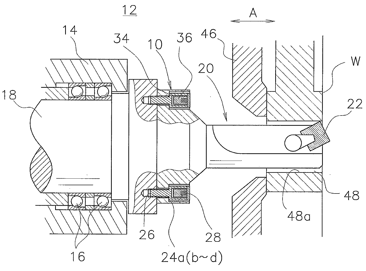
도 1은 본 발명의 제1 실시 형태에 의한 작업기계의 흔들림 방지장치(10)가 끼워넣어지는 공작기계(12)의 주요부 설명도이다.BRIEF DESCRIPTION OF THE DRAWINGS It is explanatory drawing of the principal part of the
이 공작기계(12)는, 케이싱(casing)(14) 안에 베어링(16)을 통해 회전가능하게 설치되는 스핀들(spindle)(주축)(18)과, 상기 스핀들(18)에 착탈가능한 보링바(가공공구)(20)를 구비하고, 상기 보링바(20)의 선단에 보링용 바이트(22)가 장착되어 있다.The
흔들림 방지장치(10)는, 보링바(20)를 스핀들(18)에 장착하기 위해, 상기 스핀들(18)의 축방향(화살표 A방향)에 평행한 축선을 갖는 복수, 예를 들면, 4개의 볼트부재(24a∼24d)를 구비한다. 스핀들(18)에는, 회전축을 중심으로 하는 동심원상에 소정각도씩 이격해서 4개의 나사구멍(26)이 형성되는 동시에, 보링바(20)에는, 상기 나사구멍(26)과 동축적(同軸的)으로 4개의 단(段)을 가진 구멍부(28)가 설치된다.The
도 2 및 도 3에 나타내는 바와 같이, 볼트부재(24a∼24d)는, 스핀들(18)의 나사구멍(26)에 감겨들어가는 나사부(30)를 갖는 본체부(32)를 구비한다. 본체부(32)안에는, 댐퍼실(34)이 형성되는 동시에, 이 댐퍼실(34) 안에는, 워크(W)의 가공시에 흔들림의 요인이 되는 진동에너지를, 미끄럼마찰에 의해 흡수하는 프릭션 댐퍼부(36)가 이동가능하게 수용된다. 볼트부재(24a∼24d)의 두부(頭部)(예를 들면, 육각볼트에 대응)측에는, 댐퍼실(34)을 폐색하기 위한 자성체인 캡부(38)가 장착된다.As shown in FIG.2 and FIG.3, the
프릭션 댐퍼부(36)는, 캡부(38)에 흡착되는 프릭션 댐퍼용 마그넷(40)과, 이 마그넷(40)을 고착(固着)하는 추(42)를 구비한다. 마그넷(40)은, 항상 진동을 하게 되므로, 이 마그넷(40)의 미끄럼면이 마모나 경년(經年)변화에 대해 강한 고성능을 갖는 것이 바람직하다. 마그넷(40)은, 일반적인 마그넷 이외에, 진동에 대해 강한, 예를 들면, 희토류(希土類) 마그넷이 사용된다. 캡부(38)를 구성하여 마그넷(40)이 흡착배치되는 캡 내면(38a)은, 상기 마그넷(40)을 원활하게 옆으로 미끄러지게 하기 위해 평활면(平滑面)으로 구성된다.The
댐퍼실(34)에는, 추(42)를 축방향(화살표 A방향)으로 진동(이동)가능하게 하는 간극(44a)과, 상기 추(42)를 상기 축방향에 교차하는 방향(화살표 D방향)으로 진동(이동)가능하게 하는 간극(44b)이 설치된다.In the
이렇게 구성되는 제1 실시 형태에 의한 흔들림 방지장치(10)가 끼워넣어지는 공작기계(12)의 동작에 대해, 이하에 설명한다.The operation of the
도 1에 나타내는 바와 같이, 워크(W)가 클램프장치(46)에 클램프 파지되어 있고, 공작기계(12)에는, 보링바(20)를 장착한 스핀들(18)이 회전구동되는 동시에, 상기 워크(W)의 아래구멍(48)을 따라 내보내진다. 그리고, 보링바(20)가 워크(W)의 아래구멍(48)측으로 상대적으로 이동한다. 이 때문에, 보링바(20)가 회전하고, 이 보링바(20)에 장착된 보링용 바이트(22)를 통해 아래구멍(48)을 구성하는 내벽면 (內壁面)(48a)에 보링가공이 시행된다.As shown in FIG. 1, the workpiece | work W is clamped by the
그때, 흔들림 방지장치(10)에서는, 도 4에 나타내는 바와 같이, 보링바(20)의 장착볼트로서의 기능을 갖는 볼트부재(24a∼24d)의 원심력은, 각각 외주방향으로 작용하고 있다. 이 때문에, 각 볼트부재(24a∼24d)에 있어서의 진동억제효과가 있는 방향은, 상기 볼트부재(24a∼24d)의 접힌 화살표로 나타내는 바와 같이 각각 직각방향을 향하고 있다.At this time, in the
다시 말해, 볼트부재(24a)와 볼트부재(24c)는, 화살표 E방향의 진동에 대해 작용하고, 볼트부재(24b)와 볼트부재(24d)는, 화살표 F방향의 진동에 대해 작용하며, 또한 화살표 R방향의 진동에 대해서는, 모든 볼트부재(24a∼24d)가 작용하도록 기능한다.In other words, the
이처럼, 복수의 볼트부재(24a∼24d)를 레디얼(radial)형상으로 배치함으로써, 보링바(20)가 회전을 하여도, 상기 볼트부재(24a∼24d) 중 적어도 어느 하나의 진동에 의해 억제효과를 유지할 수 있다. 따라서, 보링바(20)가 진동하는 힘(운동에너지)은, 각 볼트부재(24a∼24d)를 구성하는 마그넷(40)의 부착력에 의한 옆으로 미끄러지는 마찰에너지로 변환 소산(消散)되게 된다.In this way, by arranging the plurality of
이로써, 제1 실시 형태에서는, 새롭게 보링바(20)에 부여되는 에너지가, 마그넷(40)의 마찰력에 의해 소비 흡수되기 때문에, 간단한 구성으로, 흔들림의 발생을 유효하게 저지할 수 있다.As a result, in the first embodiment, since energy newly applied to the
더욱이, 제1 실시 형태에서는, 보링바(20)의 장착볼트로서의 기능을 갖는 볼트부재(24a∼24d)에 프릭션 댐퍼부(36)가 수용되어 있다. 이 때문에, 보링바(20)의 형상 등에 영향받지 않고, 프릭션 댐퍼부(36)를 소망의 배치상태 및 수(數)로 용이하게 끼워넣어질 수 있다. 따라서, 간단한 구성으로, 흔들림의 발생을 유효하게 저지할 수 있어, 고정밀도의 가공작업이 효율적으로 수행가능하게 된다고 하는 효과를 얻을 수 있다.Further, in the first embodiment, the
여기서, 흔들림 방지장치(10)에서는, 진동 진폭(振幅)이 작은 동안, 프릭션 댐퍼부(36)가 본체부(32) 및 캡부(38)와 일체로 진동하고 있다. 한편, 진동 진폭이 어느 크기이상에 달하면, 프릭션 댐퍼부(36)에 생기는 관성력이 마찰력보다 커진다. 이로써, 프릭션 댐퍼부(36)와 캡부(38) 사이에서 마찰 미끄럼이 발생해서 진동에너지를 흡수하여, 진동 진폭이 그 이상 커지지 않고, 자려(自勵)진동(재생(再生)흔들림)의 억제에 효과를 발휘한다.Here, in the
그리고, 제1 실시 형태에 의한 흔들림 방지장치(10)에서는, 4개의 볼트부재(24a∼24d)를 구비하고 있지만, 이에 한정되는 것이 아니다. 예를 들면, 도 5에 나타내는 바와 같이, 동심원상에 3개의 볼트부재(24a∼24c)를 소정각도씩 이격하여 설치할 수 있다. 또한, 도시하지 않지만, 5개 이상의 볼트부재를 설치함으로써, 억제효과를 한층 향상시키는 것도 가능하다.In the
또한, 육각볼트에 대응하는 볼트부재(24a∼24d)를 대신하여, 도 6에 나타내는 볼트부재(90)를 사용할 수 있다. 그리고, 볼트부재(24a∼24d)와 동일한 구성요소에는 동일한 참조부호를 부여하고, 그 상세한 설명은 생략한다.In addition, the
볼트부재(90)는, 육각구멍을 가진 볼트에 대응하고 있고, 댐퍼실(34)을 폐색(閉塞)하기 위한 자성체인 캡부(92)에는, 육각구멍(94)이 형성된다. 이 캡부(92) 는, 고정핀(96)을 통해 본체부(32)에 돌려서 고정된다.The
이 볼트부재(90)로는, 특히 두부가 본체부(32)로부터 외부로 돌출하지 않고, 도시하지 않은 워크나 지그 등에 간섭하는 것을 저지할 수 있다고 하는 효과를 얻을 수 있다.Especially with this
도 7은, 본 발명의 제2 실시 형태에 의한 작업기계의 흔들림 방지장치(50)의 단면 설명도이다. 그리고, 제1 실시 형태에 의한 흔들림 방지장치(10)와 동일한 구성요소에는 동일한 참조부호를 부여하고, 그 상세한 설명은 생략한다.Fig. 7 is a cross-sectional explanatory diagram of an
흔들림 방지장치(50)는, 복수의 볼트부재(52)를 구비하는 동시에, 상기 볼트부재(52)을 구성하는 댐퍼실(34) 안에는, 프릭션 댐퍼부(54)가 이동가능하게 수용된다. 프릭션 댐퍼부(54)는, 예를 들면 강재(鋼材) 등의 자성체로 구성되는 추(56)와, 상기 추(56)의 표면으로부터 안쪽에 배치되는 마그넷(58)을 구비한다.The
이렇게 구성되는 제2 실시 형태에서는, 마그넷(58)이 캡부재(38)의 캡 내면(38a)에 슬라이딩하지 않아, 상기 마그넷(58)의 마모에 의한 소모(消耗)가 야기되는 것을 저지할 수 있다. 더욱이, 추(56)의 재질은, 비중이 클수록, 억제 소산 에너지 효과가 커서, 강재 이외에, 납, 구리 또는 초경(超硬) 등이 적합하게 사용가능하다.In the second embodiment configured as described above, the
도 8은, 본 발명의 제3 실시 형태에 의한 공작기계(60)의 주요부 설명도이다. 그리고, 제1 실시 형태에 의한 공작기계(12)와 동일한 구성요소에는 동일한 참조부호를 부여하고, 그 상세한 설명은 생략한다. 또한, 이하에 설명하는 제4 및 제5 실시 형태에 있어서도 마찬가지로, 그 상세한 설명은 생략한다.8 is an explanatory diagram of a main part of the
공작기구(12)는, 스핀들(18)에 착탈가능한 보링바(가공공구)(62)를 구비한다. 이 보링바(62)의 선단(先端)에 중간마무리용 바이트(64a)가 장착되는 동시에, 상기 중간마무리용 바이트(64a)의 후방(後方)에는, 마무리용 바이트(64b)가 장착되어 있다.The
이처럼, 보링바(62)에는, 중간마무리용 바이트(64a) 및 마무리용 바이트(64b)가 장착되어 있어, 상기 보링바(62)에 흔들림 방지구조를 설치할 수 없다.Thus, the
그래서, 제3 실시 형태에서는, 보링바(62)를 스핀들(18)에 장착하기 위한 볼트로서의 기능을 갖는 볼트부재(24a∼25d)에, 프릭션 댐퍼부(36)가 수용되어 있다. 이로써, 보링바(62)의 형상 등에 영향받지 않고, 프릭션 댐퍼부(36)를 소망의 배치상태 및 수로 용이하게 끼워넣을 수 있어, 상기의 제1 및 제2 실시 형태와 같은 효과를 얻을 수 있다.Therefore, in the third embodiment, the
또한, 공작기계(12)는, 도 8과 같이 , 수평자세로 사용되는 이외에, 하향이나 상향 등, 여러가지 가공자세로 사용가능하다.Further, the
도 9는, 본 발명의 제4 실시 형태에 의한 흔들림 방지장치(70)를 끼워넣는 공작기계(72)의 주요부 설명도이다.9 is an explanatory view of a main part of the
공작기계(72)는, 하향의 가공자세로 사용되는 것이며, 흔들림 방지장치(70)는, 예를 들면, 4개의 볼트부재(74a∼74d)를 구비한다. 볼트부재(74a∼74d)를 구성하는 댐퍼실(34) 안에는, 프릭션 댐퍼부(76)가 이동가능하게 수용되는 동시에, 상기 프릭션 댐퍼부(76)는, 추만으로 구성된다.The
이렇게 구성되는 제4 실시 형태에서는, 프릭션 댐퍼부(추)(76)가 캡 내 면(38a)에, 직접, 슬라이딩 가능하게 재치(載置)되어 있고, 상기 프릭션 댐퍼부(76) 자체의 질량 및 중력에 의해 미끄럼마찰력이 발생한다. 따라서, 제4 실시 형태에서는, 마그넷을 사용하지 않고, 상기의 제1∼제3 실시 형태와 같은 효과를 얻는 것이 가능하게 된다.In the fourth embodiment configured as described above, the friction damper portion (weight) 76 is directly mounted on the cap
도 10은, 본 발명의 제5 실시 형태에 의한 흔들림 방지장치(80)를 끼워넣는 공작기계(82)의 주요부 설명도이다.10 is an explanatory view of a main part of the
공작기계(82)는, 상향의 가공자세로 사용되는 것이며, 흔들림 방지장치(80)는, 예를 들면 4개의 볼트부재(84a∼84d)를 구비한다. 볼트부재(84a∼84d)를 구성하는 댐퍼실(34) 안에는, 프릭션 댐퍼부(86)가 이동가능하게 수용되는 동시에, 상기 프릭션 댐퍼부(86)는, 추만으로 구성된다. 댐퍼실(34) 안에는, 프릭션 댐퍼부(86)를, 직접, 슬라이딩 가능하게 재치하기 위한 스페이서(spacer)(88)를 설치하는 것이 바람직하다. 평활한 미끄럼면을 형성하기 위해서이다.The
이렇게 구성되는 제5 실시 형태에서는, 프릭션 댐퍼부(추)(86)가 스페이서(88)에 직접 재치되어 있어, 상기 프릭션 댐퍼부(86) 자체의 질량 및 중력에 의해 미끄럼마찰력이 발생한다. 이로써, 제5 실시 형태에서는, 마그넷을 사용하지 않고, 상기의 제1∼제4 실시 형태와 같은 효과를 얻는 것이 가능하게 된다.In the fifth embodiment configured as described above, the friction damper portion (86) is placed directly on the
그리고, 상기 제4 및 제5 실시 형태에서는, 프릭션 댐퍼부(76, 86)가, 추만으로 구성되어 있지만, 이에 한정되지 않고, 반대로 상기 프릭션 댐퍼부(76, 86)를 마그넷만으로 구성할 수 있다. 그때 프릭션 댐퍼부(76, 86)는, 가능한 한 비중이 큰 마그넷으로 구성하는 것이 바람직하다.Incidentally, in the fourth and fifth embodiments, the
Claims (5)
Applications Claiming Priority (3)
| Application Number | Priority Date | Filing Date | Title |
|---|---|---|---|
| JP2006064858A JP4665800B2 (en) | 2006-02-09 | 2006-02-09 | Chatter prevention device for work machines |
| JPJP-P-2006-00064858 | 2006-02-09 | ||
| PCT/JP2007/051753 WO2007091484A1 (en) | 2006-02-09 | 2007-01-26 | Fluttering prevention device for working machine |
Publications (2)
| Publication Number | Publication Date |
|---|---|
| KR20080098583A true KR20080098583A (en) | 2008-11-11 |
| KR101100497B1 KR101100497B1 (en) | 2011-12-29 |
Family
ID=38345086
Family Applications (1)
| Application Number | Title | Priority Date | Filing Date |
|---|---|---|---|
| KR1020087015064A Expired - Fee Related KR101100497B1 (en) | 2006-02-09 | 2007-01-26 | Anti-shake device of working machine |
Country Status (5)
| Country | Link |
|---|---|
| US (1) | US8430610B2 (en) |
| EP (1) | EP1985395A1 (en) |
| JP (1) | JP4665800B2 (en) |
| KR (1) | KR101100497B1 (en) |
| WO (1) | WO2007091484A1 (en) |
Cited By (2)
| Publication number | Priority date | Publication date | Assignee | Title |
|---|---|---|---|---|
| KR200450151Y1 (en) * | 2009-12-20 | 2010-09-07 | 조중래 | Boring Machine Spindle Reinforcement Jig |
| US10010943B2 (en) | 2012-10-04 | 2018-07-03 | Korea Institute Of Machinery & Materials | Apparatus and method for attenuation of vibration in machine tool |
Families Citing this family (7)
| Publication number | Priority date | Publication date | Assignee | Title |
|---|---|---|---|---|
| JP6145915B2 (en) * | 2012-11-02 | 2017-06-14 | エヌティーエンジニアリング株式会社 | Chattering prevention structure of work machine and chattering prevention method thereby |
| WO2014087757A1 (en) * | 2012-12-03 | 2014-06-12 | 村田機械株式会社 | Vibration reduction device for machine tool |
| US9993879B1 (en) | 2016-12-05 | 2018-06-12 | Kennametal Inc | Eddy current vibration absorber assembly for cutting tool |
| FR3109903B1 (en) * | 2020-05-07 | 2022-04-15 | Hutchinson | Boring bar fitted with electrodynamic actuators to counter vibrations and machine tool fitted with such a bar. |
| CN111843526A (en) * | 2020-07-22 | 2020-10-30 | 湖南中大创远数控装备有限公司 | Main shaft mechanism and machine tool |
| CN114192855B (en) * | 2021-12-02 | 2023-04-18 | 北京航空航天大学 | Vibration reduction milling cutter |
| CN115167121B (en) * | 2022-06-08 | 2025-10-10 | 西安交通大学 | Intelligent spindle micro-vibration control method and system based on digital twin model drive |
Family Cites Families (14)
| Publication number | Priority date | Publication date | Assignee | Title |
|---|---|---|---|---|
| US11032A (en) * | 1854-06-06 | Improvement in seed-planters | ||
| GB1051548A (en) * | 1963-09-07 | |||
| US3643546A (en) * | 1969-12-18 | 1972-02-22 | Cincinnati Milacron Inc | Tuned damping means for increasing the minimum dynamic stiffness of a spindle system |
| JP3631902B2 (en) * | 1998-05-15 | 2005-03-23 | 三菱重工業株式会社 | Vibration reduction damper |
| JP2000052176A (en) * | 1998-06-04 | 2000-02-22 | Manyoo Tool Kk | Tool holder |
| JP2000107976A (en) | 1998-10-07 | 2000-04-18 | Toshiba Mach Co Ltd | Machine tool |
| DE10032073B4 (en) * | 2000-07-01 | 2015-02-05 | Reishauer Ag | Detachable, highly accurate and rigid connection of a tool, workpiece or measuring device carrier with a spindle head of a machine tool spindle |
| US6484971B2 (en) * | 2000-07-24 | 2002-11-26 | Thombi Layukallo | Control of flow separation and related phenomena on aerodynamic surfaces |
| JP4552214B2 (en) * | 2000-09-05 | 2010-09-29 | エヌティーエンジニアリング株式会社 | Chatter prevention structure for work machines |
| JP2002161909A (en) * | 2000-11-24 | 2002-06-07 | Honda Motor Co Ltd | Damping bolt |
| TW505830B (en) | 2001-04-03 | 2002-10-11 | Ebauchesfabrik Eta Ag | Timepiece movement |
| US6619165B2 (en) * | 2002-02-01 | 2003-09-16 | Kennametal Inc. | Tunable toolholder |
| JP2004066443A (en) * | 2002-06-10 | 2004-03-04 | Nikken Kosakusho Works Ltd | Tool holder |
| JP4475899B2 (en) * | 2003-08-29 | 2010-06-09 | 大昭和精機株式会社 | Tool holder |
-
2006
- 2006-02-09 JP JP2006064858A patent/JP4665800B2/en not_active Expired - Fee Related
-
2007
- 2007-01-26 US US12/158,900 patent/US8430610B2/en not_active Expired - Fee Related
- 2007-01-26 KR KR1020087015064A patent/KR101100497B1/en not_active Expired - Fee Related
- 2007-01-26 WO PCT/JP2007/051753 patent/WO2007091484A1/en not_active Ceased
- 2007-01-26 EP EP07713768A patent/EP1985395A1/en not_active Withdrawn
Cited By (2)
| Publication number | Priority date | Publication date | Assignee | Title |
|---|---|---|---|---|
| KR200450151Y1 (en) * | 2009-12-20 | 2010-09-07 | 조중래 | Boring Machine Spindle Reinforcement Jig |
| US10010943B2 (en) | 2012-10-04 | 2018-07-03 | Korea Institute Of Machinery & Materials | Apparatus and method for attenuation of vibration in machine tool |
Also Published As
| Publication number | Publication date |
|---|---|
| JP4665800B2 (en) | 2011-04-06 |
| JP2007210088A (en) | 2007-08-23 |
| US20090202313A1 (en) | 2009-08-13 |
| KR101100497B1 (en) | 2011-12-29 |
| EP1985395A1 (en) | 2008-10-29 |
| WO2007091484A1 (en) | 2007-08-16 |
| US8430610B2 (en) | 2013-04-30 |
Similar Documents
| Publication | Publication Date | Title |
|---|---|---|
| KR101100497B1 (en) | Anti-shake device of working machine | |
| KR102584750B1 (en) | Tool spindle and machine tool inclduing the same | |
| KR101312037B1 (en) | Chattering vibration inhibiting mechanism of machine tool | |
| CN1091671C (en) | tombstone fixture | |
| KR20090107974A (en) | Tool holder with damping means | |
| JP6145915B2 (en) | Chattering prevention structure of work machine and chattering prevention method thereby | |
| JP7069540B2 (en) | Work machine chatter prevention structure | |
| JP2018513024A (en) | Method to reduce regenerative vibration of cutting machine | |
| KR101332467B1 (en) | Anti-vibration structure of cutting tool | |
| CN201067809Y (en) | a boring bar | |
| CN101076419A (en) | Clamping device | |
| KR101258519B1 (en) | Apparatus for damping vibration of tool carriage in lathe | |
| WO2006010093A1 (en) | Variable tuned holder for machine tools | |
| JP4957102B2 (en) | Processing method and dynamic vibration absorber | |
| JP2009006434A (en) | Spindle device and its natural frequency adjustment method | |
| CN115213705B (en) | A cutting mechanism for suppressing cutting chatter | |
| JP5728824B2 (en) | Tool chatter prevention device | |
| JP6769030B2 (en) | Spindle equipment and machine tools | |
| JP3944321B2 (en) | Dynamic vibration absorber and machine tool | |
| KR20110113867A (en) | Dustproof device and cutting tool equipped with the dustproof device | |
| JP2010201587A (en) | Main spindle device | |
| US20250289087A1 (en) | Mass damper assembly for vertical turning center | |
| RU2746729C1 (en) | Vibration damping tool extension for deep drilling | |
| JP6326276B2 (en) | Crankshaft mirror tool holding device | |
| US20130058733A1 (en) | Rod-shaped tool holder for attaching cutting bits at nodes |
Legal Events
| Date | Code | Title | Description |
|---|---|---|---|
| PA0105 | International application |
St.27 status event code: A-0-1-A10-A15-nap-PA0105 |
|
| P11-X000 | Amendment of application requested |
St.27 status event code: A-2-2-P10-P11-nap-X000 |
|
| P13-X000 | Application amended |
St.27 status event code: A-2-2-P10-P13-nap-X000 |
|
| PG1501 | Laying open of application |
St.27 status event code: A-1-1-Q10-Q12-nap-PG1501 |
|
| A201 | Request for examination | ||
| PA0201 | Request for examination |
St.27 status event code: A-1-2-D10-D11-exm-PA0201 |
|
| E902 | Notification of reason for refusal | ||
| PE0902 | Notice of grounds for rejection |
St.27 status event code: A-1-2-D10-D21-exm-PE0902 |
|
| E13-X000 | Pre-grant limitation requested |
St.27 status event code: A-2-3-E10-E13-lim-X000 |
|
| P11-X000 | Amendment of application requested |
St.27 status event code: A-2-2-P10-P11-nap-X000 |
|
| P13-X000 | Application amended |
St.27 status event code: A-2-2-P10-P13-nap-X000 |
|
| E701 | Decision to grant or registration of patent right | ||
| PE0701 | Decision of registration |
St.27 status event code: A-1-2-D10-D22-exm-PE0701 |
|
| GRNT | Written decision to grant | ||
| PR0701 | Registration of establishment |
St.27 status event code: A-2-4-F10-F11-exm-PR0701 |
|
| PR1002 | Payment of registration fee |
St.27 status event code: A-2-2-U10-U12-oth-PR1002 Fee payment year number: 1 |
|
| PG1601 | Publication of registration |
St.27 status event code: A-4-4-Q10-Q13-nap-PG1601 |
|
| FPAY | Annual fee payment |
Payment date: 20141118 Year of fee payment: 4 |
|
| PR1001 | Payment of annual fee |
St.27 status event code: A-4-4-U10-U11-oth-PR1001 Fee payment year number: 4 |
|
| FPAY | Annual fee payment |
Payment date: 20151021 Year of fee payment: 5 |
|
| PR1001 | Payment of annual fee |
St.27 status event code: A-4-4-U10-U11-oth-PR1001 Fee payment year number: 5 |
|
| FPAY | Annual fee payment |
Payment date: 20161209 Year of fee payment: 6 |
|
| PR1001 | Payment of annual fee |
St.27 status event code: A-4-4-U10-U11-oth-PR1001 Fee payment year number: 6 |
|
| FPAY | Annual fee payment |
Payment date: 20171117 Year of fee payment: 7 |
|
| PR1001 | Payment of annual fee |
St.27 status event code: A-4-4-U10-U11-oth-PR1001 Fee payment year number: 7 |
|
| PR1001 | Payment of annual fee |
St.27 status event code: A-4-4-U10-U11-oth-PR1001 Fee payment year number: 8 |
|
| FPAY | Annual fee payment |
Payment date: 20191002 Year of fee payment: 9 |
|
| PR1001 | Payment of annual fee |
St.27 status event code: A-4-4-U10-U11-oth-PR1001 Fee payment year number: 9 |
|
| PC1903 | Unpaid annual fee |
St.27 status event code: A-4-4-U10-U13-oth-PC1903 Not in force date: 20201223 Payment event data comment text: Termination Category : DEFAULT_OF_REGISTRATION_FEE |
|
| PC1903 | Unpaid annual fee |
St.27 status event code: N-4-6-H10-H13-oth-PC1903 Ip right cessation event data comment text: Termination Category : DEFAULT_OF_REGISTRATION_FEE Not in force date: 20201223 |