KR20070109511A - Tripod type constant velocity joint - Google Patents
Tripod type constant velocity joint Download PDFInfo
- Publication number
- KR20070109511A KR20070109511A KR1020060042572A KR20060042572A KR20070109511A KR 20070109511 A KR20070109511 A KR 20070109511A KR 1020060042572 A KR1020060042572 A KR 1020060042572A KR 20060042572 A KR20060042572 A KR 20060042572A KR 20070109511 A KR20070109511 A KR 20070109511A
- Authority
- KR
- South Korea
- Prior art keywords
- roller
- constant velocity
- velocity joint
- inner roller
- circumferential surface
- Prior art date
Links
Images


Classifications
-
- F—MECHANICAL ENGINEERING; LIGHTING; HEATING; WEAPONS; BLASTING
- F16—ENGINEERING ELEMENTS AND UNITS; GENERAL MEASURES FOR PRODUCING AND MAINTAINING EFFECTIVE FUNCTIONING OF MACHINES OR INSTALLATIONS; THERMAL INSULATION IN GENERAL
- F16D—COUPLINGS FOR TRANSMITTING ROTATION; CLUTCHES; BRAKES
- F16D3/00—Yielding couplings, i.e. with means permitting movement between the connected parts during the drive
- F16D3/16—Universal joints in which flexibility is produced by means of pivots or sliding or rolling connecting parts
- F16D3/20—Universal joints in which flexibility is produced by means of pivots or sliding or rolling connecting parts one coupling part entering a sleeve of the other coupling part and connected thereto by sliding or rolling members
- F16D3/202—Universal joints in which flexibility is produced by means of pivots or sliding or rolling connecting parts one coupling part entering a sleeve of the other coupling part and connected thereto by sliding or rolling members one coupling part having radially projecting pins, e.g. tripod joints
- F16D3/205—Universal joints in which flexibility is produced by means of pivots or sliding or rolling connecting parts one coupling part entering a sleeve of the other coupling part and connected thereto by sliding or rolling members one coupling part having radially projecting pins, e.g. tripod joints the pins extending radially outwardly from the coupling part
- F16D3/2055—Universal joints in which flexibility is produced by means of pivots or sliding or rolling connecting parts one coupling part entering a sleeve of the other coupling part and connected thereto by sliding or rolling members one coupling part having radially projecting pins, e.g. tripod joints the pins extending radially outwardly from the coupling part having three pins, i.e. true tripod joints
-
- F—MECHANICAL ENGINEERING; LIGHTING; HEATING; WEAPONS; BLASTING
- F16—ENGINEERING ELEMENTS AND UNITS; GENERAL MEASURES FOR PRODUCING AND MAINTAINING EFFECTIVE FUNCTIONING OF MACHINES OR INSTALLATIONS; THERMAL INSULATION IN GENERAL
- F16D—COUPLINGS FOR TRANSMITTING ROTATION; CLUTCHES; BRAKES
- F16D3/00—Yielding couplings, i.e. with means permitting movement between the connected parts during the drive
- F16D3/16—Universal joints in which flexibility is produced by means of pivots or sliding or rolling connecting parts
- F16D3/20—Universal joints in which flexibility is produced by means of pivots or sliding or rolling connecting parts one coupling part entering a sleeve of the other coupling part and connected thereto by sliding or rolling members
- F16D3/202—Universal joints in which flexibility is produced by means of pivots or sliding or rolling connecting parts one coupling part entering a sleeve of the other coupling part and connected thereto by sliding or rolling members one coupling part having radially projecting pins, e.g. tripod joints
- F16D3/205—Universal joints in which flexibility is produced by means of pivots or sliding or rolling connecting parts one coupling part entering a sleeve of the other coupling part and connected thereto by sliding or rolling members one coupling part having radially projecting pins, e.g. tripod joints the pins extending radially outwardly from the coupling part
-
- F—MECHANICAL ENGINEERING; LIGHTING; HEATING; WEAPONS; BLASTING
- F16—ENGINEERING ELEMENTS AND UNITS; GENERAL MEASURES FOR PRODUCING AND MAINTAINING EFFECTIVE FUNCTIONING OF MACHINES OR INSTALLATIONS; THERMAL INSULATION IN GENERAL
- F16D—COUPLINGS FOR TRANSMITTING ROTATION; CLUTCHES; BRAKES
- F16D3/00—Yielding couplings, i.e. with means permitting movement between the connected parts during the drive
- F16D3/16—Universal joints in which flexibility is produced by means of pivots or sliding or rolling connecting parts
- F16D3/20—Universal joints in which flexibility is produced by means of pivots or sliding or rolling connecting parts one coupling part entering a sleeve of the other coupling part and connected thereto by sliding or rolling members
- F16D3/202—Universal joints in which flexibility is produced by means of pivots or sliding or rolling connecting parts one coupling part entering a sleeve of the other coupling part and connected thereto by sliding or rolling members one coupling part having radially projecting pins, e.g. tripod joints
- F16D2003/2026—Universal joints in which flexibility is produced by means of pivots or sliding or rolling connecting parts one coupling part entering a sleeve of the other coupling part and connected thereto by sliding or rolling members one coupling part having radially projecting pins, e.g. tripod joints with trunnion rings, i.e. with tripod joints having rollers supported by a ring on the trunnion
-
- Y—GENERAL TAGGING OF NEW TECHNOLOGICAL DEVELOPMENTS; GENERAL TAGGING OF CROSS-SECTIONAL TECHNOLOGIES SPANNING OVER SEVERAL SECTIONS OF THE IPC; TECHNICAL SUBJECTS COVERED BY FORMER USPC CROSS-REFERENCE ART COLLECTIONS [XRACs] AND DIGESTS
- Y10—TECHNICAL SUBJECTS COVERED BY FORMER USPC
- Y10S—TECHNICAL SUBJECTS COVERED BY FORMER USPC CROSS-REFERENCE ART COLLECTIONS [XRACs] AND DIGESTS
- Y10S464/00—Rotary shafts, gudgeons, housings, and flexible couplings for rotary shafts
- Y10S464/904—Homokinetic coupling
- Y10S464/905—Torque transmitted via radially extending pin
Abstract
Description
도 1a는 일반적인 등속 조인트의 단면 구성도이고, 도 1b는 도 1a의 A-A선 단면도이다.1A is a cross-sectional configuration diagram of a general constant velocity joint, and FIG. 1B is a cross-sectional view taken along the line A-A of FIG. 1A.
도 2는 종래의 다른 구성의 트라이포드식 등속 조인트의 단면도이다.2 is a cross-sectional view of a tripod constant velocity joint of another conventional configuration.
도 3a는 도 2의 종래의 트라이포드식 등속조인트에서 나타나는 등속조인트에서 접촉면적과 상대운동을 설명하기 위한 단면도이고, 도 3b는 도 3a의 횡단면도이다.Figure 3a is a cross-sectional view for explaining the contact area and the relative motion in the constant velocity joint shown in the conventional tripod constant velocity joint of Figure 2, Figure 3b is a cross-sectional view of Figure 3a.
도 4a은 종래의 또다른 트라이포드식 등속 조인트의 횡단면도이고, 도 4b는 도 4a의 I-I선 단면도이다.4A is a cross sectional view of another conventional tripod constant velocity joint, and FIG. 4B is a sectional view taken along line II of FIG. 4A.
도 5a 및 도 5b는 도 4의 종래의 트라이포드식 등속조인트에서 나타나는 등속조인트에서 접촉면적과 상대운동을 설명하기 위한 종단면도이다.5a and 5b are longitudinal cross-sectional views for explaining the contact area and the relative motion in the constant velocity joint shown in the conventional tripod constant velocity joint of FIG.
도 6a는 이 발명의 제1 실시예에 따른 트라이포드식 등속조인트의 단면 구성도이고, 도 6b는 이 발명의 제1 실시예에 따른 트라이포드식 등속조인트의 스파이더의 사시 구성도이다.6A is a cross-sectional configuration diagram of the tripod constant velocity joint according to the first embodiment of the present invention, and FIG. 6B is a perspective configuration diagram of a spider of the tripod constant velocity joint according to the first embodiment of the present invention.
도 7a 내지 도 7e는 이 발명의 제1 실시예에 따른 트라이포드식 등속조인트의 트러니언의 다른 형태를 나타낸 사시도이다.7A to 7E are perspective views showing another form of the trunnion of the tripod constant velocity joint according to the first embodiment of the present invention.
도 8a 내지 도 8c는 이 발명의 제1 실시예에 따른 트라이포드식 등속조인트 의 트러니언의 인너롤러와의 접촉방법을 나타낸 도면이다.8A to 8C show a contact method of the trunnion with the inner roller of the trunnion constant velocity joint according to the first embodiment of the present invention.
도 9는 이 발명의 제1 실시예에 따른 트라이포드식 등속조인트의 응력집중 상태를 보이기 위한 단면 구성도이다. 9 is a cross-sectional view for showing a stress concentration state of the tripod constant velocity joint according to the first embodiment of the present invention.
도 10a 및 도 10b는 이 발명의 제1 실시예에 따른 트라이포드식 등속조인트의 트러니언에서의 윤활제의 이동가능한 경로를 설명하기 위한 사시도이다.10A and 10B are perspective views for explaining the movable path of the lubricant in the trunnion of the tripod constant velocity joint according to the first embodiment of the present invention.
도 11은 이 발명의 제1 실시예에 따른 트라이포드식 등속조인트의 롤러 어셈블리의 폭의 관계를 설명하기 위한 단면도이다.11 is a cross-sectional view for explaining the relationship between the widths of the roller assemblies of the tripod constant velocity joint according to the first embodiment of the present invention.
도 12는 이 발명의 제1 실시예에 따른 트라이포드식 등속조인트의 다른 롤러 어셈블리의 폭의 관계를 설명하기 위한 단면도이다.12 is a cross-sectional view for explaining the relationship between the widths of the other roller assemblies of the tripod constant velocity joint according to the first embodiment of the present invention.
도 13a는 이 발명의 제2 실시예에 따른 트라이포드식 등속조인트 단면 구성도이고, 도 13b는 이 발명의 제2 실시예에 따른 트라이포드식 등속조인트의 트러니언의 사시 구성도이다.FIG. 13A is a cross-sectional configuration of a tripod constant velocity joint according to a second embodiment of the present invention, and FIG. 13B is a perspective configuration diagram of a trunnion of a tripod constant velocity joint according to a second embodiment of the present invention.
도 14는 이 발명의 제2 실시예에 따른 트라이포드식 등속조인트의 트러니언의 다른 형태를 나타낸 사시도이다.14 is a perspective view showing another form of the trunnion of the tripod constant velocity joint according to the second embodiment of the present invention.
도 15a 및 도 15b는 이 발명의 제2 실시예에 따른 트라이포드식 등속조인트의 트러니언의 인너롤러와의 접촉면을 나타낸 사시도이다.15A and 15B are perspective views showing a contact surface of an inner roller of a trunnion of a tripod constant velocity joint according to a second embodiment of the present invention.
도 16은 이 발명의 제2 실시예에 따른 트라이포드식 등속조인트의 응력집중 상태를 보이기 위한 단면 구성도이다. 16 is a cross-sectional configuration diagram for showing a stress concentration state of the tripod constant velocity joint according to the second embodiment of the present invention.
도 17a 및 도 17b는 이 발명의 제2 실시예에 따른 트라이포드식 등속조인트의 트러니언에서의 윤활제의 이동가능한 경로를 설명하기 위한 사시도이다.17A and 17B are perspective views for explaining the movable path of the lubricant in the trunnion of the tripod constant velocity joint according to the second embodiment of the present invention.
도 18은 이 발명의 제2 실시예에 따른 트라이포드식 등속조인트의 롤러 어셈블리의 폭의 관계를 설명하기 위한 단면도이다.18 is a cross-sectional view for explaining the relationship between the widths of the roller assemblies of the tripod constant velocity joint according to the second embodiment of the present invention.
도 19는 이 발명의 제2 실시예에 따른 트라이포드식 등속조인트의 다른 롤러 어셈블리의 폭의 관계를 설명하기 위한 단면도이다.19 is a cross-sectional view for explaining the relationship between the widths of the other roller assemblies of the tripod constant velocity joint according to the second embodiment of the present invention.
도 20a는 이 발명의 제3 실시예에 따른 트라이포드식 등속조인트 단면 구성도이고, 도 20b는 이 발명의 제3 실시예에 따른 트라이포드식 등속조인트의 트러니언의 사시 구성도이다.20A is a cross-sectional configuration of a tripod constant velocity joint according to a third embodiment of the present invention, and FIG. 20B is a perspective configuration diagram of a trunnion of a tripod constant velocity joint according to a third embodiment of the present invention.
도 21a 및 도 21b는 이 발명의 제3 실시예에 따른 트라이포드식 등속조인트의 트러니언의 인너롤러와의 접촉면을 나타낸 사시도이다.21A and 21B are perspective views showing a contact surface of a trunnion inner roller of a tripod constant velocity joint according to a third embodiment of the present invention.
도 22는 이 발명의 제3 실시예에 따른 트라이포드식 등속조인트의 응력집중 상태를 보이기 위한 단면 구성도이다. FIG. 22 is a cross-sectional view illustrating a stress concentration state of the tripod constant velocity joint according to the third embodiment of the present invention. FIG.
도 23a 및 도 23b는 이 발명의 제3 실시예에 따른 트라이포드식 등속조인트의 트러니언에서의 윤활제의 이동가능한 경로를 설명하기 위한 사시도이다.23A and 23B are perspective views for explaining the movable path of the lubricant in the trunnion of the tripod constant velocity joint according to the third embodiment of the present invention.
도 24는 이 발명의 제3 실시예에 따른 트라이포드식 등속조인트의 롤러 어셈블리의 폭의 관계를 설명하기 위한 단면도이다.24 is a cross-sectional view for explaining the relationship between the widths of the roller assemblies of the tripod constant velocity joint according to the third embodiment of the present invention.
도 25는 이 발명의 제3 실시예에 따른 트라이포드식 등속조인트의 다른 롤러 어셈블리의 폭의 관계를 설명하기 위한 단면도이다.25 is a cross-sectional view for explaining the relationship between the widths of the other roller assemblies of the tripod constant velocity joint according to the third embodiment of the present invention.
* 도면의 주요 부분에 대한 부호의 설명 *Explanation of symbols on the main parts of the drawings
20 : 하우징 21 : 스파이더20
22 : 트러니언 23 : 인너롤러22: trunnion 23: inner roller
24 : 니들롤러 25 : 아우터롤러24: needle roller 25: outer roller
26 : 리테이너링 27 : 리테이너 클립26: retainer ring 27: retainer clip
이 발명은 등속 조인트 분야에 관한 것으로서, 좀더 세부적으로 말하자면 2개 이상의 다각형 평면을 갖는 다면체 트러니언을 이용하여 인너롤러의 내주면과 다수의 접촉부를 가질 수 있도록 함으로써 동력을 전달함에 있어 안정성을 갖게 되고, 한점에 구동력이 집중되어 면압이 상승하는 것을 방지할 수 있으며, 면전체가 접촉하여 필요이상의 마찰력을 일으키는 것을 막음과 동시에, 상대 운동이 적은 부분에는 다면체 트러니언의 직선부를 이용하여 원활한 윤활이 이루어지도록 하여 마찰력을 줄임으로써 축방향의 힘을 억제하여 차량의 진동을 저감시키고 내구성을 향상시킬 수 있는, 트라이포드식 등속조인트에 관한 것이다.The present invention relates to the field of constant velocity joints, and more specifically, by using a polyhedral trunnion having two or more polygonal planes, the inner circumferential surface of the inner roller can have a plurality of contacts, thereby making it stable in transmitting power. It is possible to prevent the surface pressure from rising due to the concentration of driving force at one point, and to prevent the friction of the whole surface from generating more friction force, and to smooth the lubrication by using the straight part of the polyhedral trunnion in the part with less relative movement. Therefore, the present invention relates to a tripod constant velocity joint, which can suppress axial force to reduce vibration of a vehicle and improve durability.
일반적으로 조인트는 회전축의 각도가 서로 다른 회전축에 회전동력(토크)을 전달하기 위한 것으로서, 동력전달 각도가 작은 추진축의 경우에는 후크 조인트, 플렉시블 조인트 등이 사용되고, 동력전달 각도가 큰 전륜 구동차의 구동축의 경우에는 등속 조인트가 사용된다. In general, a joint is used to transmit rotational power (torque) to a rotation shaft having different angles of rotation. In the case of a propulsion shaft having a small power transmission angle, a hook joint or a flexible joint is used, and a drive shaft of a front wheel drive vehicle having a large power transmission angle is used. In the case of constant velocity joints are used.
상기한 등속 조인트는 구동축과 피동축의 교차각이 큰 경우에도 등속으로 원활하게 동력을 전달할 수 있기 때문에 독립 현가 방식의 전륜 구동차의 액슬축에 주로 사용되며, 샤프트를 중심으로 엔진측은 트라이포드식 등속 조인트로 이루어지 고, 샤프트를 중심으로 타이어측은 버필드식 등속 조인트로 이루어진다. The constant velocity joint is mainly used for the axle shaft of an independent suspension type front wheel drive vehicle because it can smoothly transmit power at constant speed even when the drive shaft and the driven shaft have a large crossing angle, and the engine side is a tripod constant velocity around the shaft. It consists of a joint, and the tire side around the shaft consists of a Burfield type constant velocity joint.
도 1a는 일반적인 등속 조인트의 단면 구성도이고, 도 1b는 도 1a의 A-A선 단면도이다. 도 1a 및 도 1b에 도시되어 있는 바와 같이 일반적인 등속 조인트의 구성은, 샤프트(1)를 중심으로 우측(엔진측)은 트라이포드식 등속 조인트로 이루어지고, 샤프트(1)를 중심으로 좌측(바퀴측)은 버필드식 등속 조인트로 이루어진다. 1A is a cross-sectional configuration diagram of a general constant velocity joint, and FIG. 1B is a cross-sectional view taken along the line A-A of FIG. 1A. As shown in FIG. 1A and FIG. 1B, the structure of a general constant velocity joint is a tripod-type constant velocity joint with the right side (engine side) centering around the
샤프트(1)를 중심으로 우측(엔진측)에 설치되어 있는 상기한 트라이포드식 등속 조인트의 구성은, 엔진(도시되지 않음)의 회전동력을 전달하며 내부에 트랙홈이 형성되어 있는 하우징(2)과, 상기한 하우징(2)의 회전동력을 전달받아서 회전되는 샤프트(1)와, 상기한 하우징(2)과 샤프트(1)를 연결하기 위하여 상기한 샤프트(1)의 일단에 연결되어 상기한 하우징(2)의 내부에 설치되며 3개의 트러니언이 형성되어 상기한 트랙홈에 삽입되는 스파이더(3)와, 상기한 스파이더(3)의 트러니언의 외주면에 설치되는 니들롤러(6)와, 상기한 니들롤러(6)의 외주면에 설치되는 인너롤러(5)와, 상기한 인너롤러(5)의 외주면에 설치되어 상기한 하우징(2)과 샤프트(1)의 마찰을 감소시키는 아우터롤러(4)와, 상기한 니들롤러(6) 및 인너롤러(5)의 상단에 설치되는 리테이너링(8)과, 상기한 하우징(2)에 일단이 연결되고 상기한 샤프트(1)에 일단이 연결되는 부트(10)와, 상기한 부트(10)를 각각 고정시키기 위한 클램핑 밴드(11, 12)를 포함하여 이루어진다.The above-described configuration of the tripod constant velocity joint, which is provided on the right side (engine side) around the
샤프트(1)를 중심으로 좌측(타이어측)에 설치되어 있는 상기한 버필드식 등속 조인트의 구성은, 상기한 트라이포드식 등속 조인트의 회전동력을 전달받아서 회전되는 샤프트(1)의 일단에 연결설치되는 인너레이스(15)와, 상기한 인너레이 스(15)의 외부에 설치되는 아웃터레이스(13)와, 상기한 인너레이스(15)의 회전동력을 상기한 아웃터레이스(13)에 전달하기 위한 볼(16)과, 상기한 볼(16)을 지지하기 위한 케이지(14)와, 상기한 아웃터 레이스(13)의 외부에 설치되는 센서링(17)과, 상기한 샤프트(1)에 일단이 연결되고 상기한 아웃터 레이스(13)에 일단이 연결되는 부트(18)와, 상기한 부트(18)를 고정시키기 위한 클램핑 밴드(19, 20)를 포함하여 이루어진다.The above-described configuration of the Burfield type constant velocity joint provided on the left side (tire side) around the
상기한 구성에 의한 일반적인 등속 조인트의 작용은 다음과 같다.The action of the general constant velocity joint by the above configuration is as follows.
엔진(도시되지 않음)으로부터 출력된 회전동력이 트랜스미션(도시되지 않음)을 거쳐 하우징(2)에 전달되면 하우징(2)이 회전되며, 이러한 하우징(2)의 회전동력은 아우터롤러(4), 인너롤러(5), 니들롤러(6)를 통해 스파이더(3)로 전달됨으로써 스파이더(3)에 연결되어 있는 샤프트(1)를 회전시킨다. 또한, 상기한 샤프트(1)의 회전동력은 인너레이스(15)와 볼(16)을 거쳐 아웃터 레이스(13)로 전달됨으로써 아웃터 레이스(13)에 연결되는 바퀴(도시되지 않음)를 회전시키게 된다.When the rotational power output from the engine (not shown) is transmitted to the
이 경우에, 샤프트(1)를 중심으로 우측(엔진측)에 설치되어 있는 트라이포드식 등속 조인트에서는 아우터롤러(4)가 하우징(2)의 트랙홈내를 슬라이딩 이동함으로써 아우터롤러(4)와 연관되어 있는 샤프트(1)의 회전 각도가 달라지게 됨으로써 차량의 변위에 따라 절각이 되고, 샤프트(1)를 중심으로 좌측(바퀴측)에 설치되어 있는 버필드식 등속 조인트에서는 볼(16)에 의해 아웃터 레이스(13)의 회전각도가 달라지게 됨으로써 차량의 변위에 따라 절각이 된다. In this case, in the tripod constant velocity joint provided on the right side (engine side) around the
또한, 트라이포드식 등속 조인트측의 부트(10)와 버필드식 등속 조인트측의 부트(18)는 각각 트라이포드식 등속 조인트와 버필드식 등속 조인트의 외부를 감싸 밀봉시킴으로써 트라이포드식 등속 조인트와 버필드식 등속 조인트가 외부 오염물질에 의해 손상되는 것을 방지한다.In addition, the
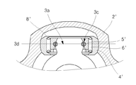
도 2는 도 1에 도시되어 있는 트라이포드식 등속 조인트와는 다른 구성의 트라이포드식 등속 조인트의 횡단면도이다. 도 2에 도시되어 있는 바와 같이 종래의 트라이포드식 등속 조인트의 다른 구성은, 임의의 곡면형상의 안내면을 갖는 3개의 트랙홈이 형성되는 하우징(2')과, 3개의 구형 트러니온(3a)이 돌출 형성되어 상기한 트랙홈에 삽입되는 스파이더(3')와, 상기한 구형 트러니온(3a)의 주위를 감싸면서 설치되며 상기한 구형 트러니온(3a)과의 접촉면이 오목형상면을 가지는 인너롤러(5')와, 상기한 인너롤러(5')의 주위로 배치된 다수의 니들롤러(6')와, 상기한 니들롤러(6')를 통해 회전하는 아우터 롤러(4')와, 상기한 니들롤러(6')의 이탈을 방지하기 위해 설치되는 리테이너링(8')을 포함하여 이루어진다. FIG. 2 is a cross-sectional view of a tripod constant velocity joint having a configuration different from that of the tripod constant velocity joint shown in FIG. 1. As shown in FIG. 2, another configuration of the conventional tripod constant velocity joint includes a housing 2 'in which three track grooves having arbitrary curved guide surfaces are formed, and three
상기한 구성에 의한 종래의 트라이포드식 등속 조인트의 작용은 다음과 같다.The action of the conventional tripod constant velocity joint according to the above configuration is as follows.
하우징(2')에 동력이 전달되어 회전을 하게 되면 아우터롤러(4'), 니들롤러(6'), 인너롤러(5')를 통해 트러니언(3a)에 동력을 전달하여 스파이더(3)를 회전시킨다. 이때, 니들롤러(6')를 통해 상대회전이 가능하게 결합된 인너롤러(5')와 아우터롤러(4')의 조합은 하우징(2')의 가이드면을 따라 트랙홈의 축방향으로 안내되고, 인너롤러(5')의 오목형상면과 구형 트러니언(3a)의 사이에서 조심운동(중심조절 및 요동)이 일어난다. When power is transmitted to the housing 2 'and rotates, the
그러나, 이와 같이 스파이더(3)의 기울음을 구형 트러니언(3a)을 통해 스스로 흡수하여 조정하기 위한 조심운동이 일어나는 경우에, 도 3a 및 도 3b에 도시되어 있는 바와 같이, 인너롤러(5')의 오목형상면과 구형 트러니언(3a)의 상대운동에 대한 접촉면적(3b)이 넓기 때문에 마찰력이 커지고 조심운동의 중심축선(3d)과 구형 트러니언(3a)의 외주면이 만나는 점(3c)에서는 상대 운동량이 적기 때문에 장시간 연속해서 부하를 받아 회전할 경우 윤활불량을 일으켜 회전 내구성의 저하를 일으키는 문제점이 있다. However, in the case where the careful movement for absorbing and adjusting the inclination of the
도 4a는 또다른 구성의 종래의 트라이포드식 등속 조인트의 단면도이고, 도 4b는 도 4a의 I-I선 단면도이다. 도 4a 및 도 4b에 도시되어 있는 바와 같이 종래의 트라이포드식 등속 조인트의 또다른 구성은, 임의의 곡면형상의 안내면을 갖는 3개의 트랙홈이 형성되는 하우징(2")과, 3개의 타원형 트러니온(3e)이 돌출 형성되어 상기한 트랙홈에 삽입되는 스파이더(3")와, 상기한 타원형 트러니온(3e)의 주위를 감싸면서 설치되며 상기한 타원형 트러니언(3e)과의 접촉면이 볼록형상면을 가지는 인너롤러(5")와, 상기한 인너롤러(5")의 주위로 배치된 다수의 니들롤러(6")와, 상기한 니들롤러(6")를 통해 회전하는 아우터 롤러(4")와, 상기한 니들롤러(6")와 인너롤러(5")의 이탈을 방지하기 위해 설치되는 리테이너링(8")을 포함하여 이루어진다. 4A is a cross-sectional view of a conventional tripod constant velocity joint of another configuration, and FIG. 4B is a cross-sectional view taken along line II of FIG. 4A. Another configuration of a conventional tripod constant velocity joint, as shown in FIGS. 4A and 4B, is a
상기한 구성에 의한 종래의 트라이포드식 등속 조인트의 작용은 다음과 같다. The action of the conventional tripod constant velocity joint according to the above configuration is as follows.
하우징(2")에 동력이 전달되어 회전을 하게 되면 아우터롤러(4"), 니들롤 러(6"), 인너롤러(5")를 통해 타원형 트러니언(3e)에 동력을 전달하여 스파이더(3")를 회전시킨다. 이때 니들롤러(6")를 통해 상대회전이 가능하게 결합된 인너롤러(5")와 아우터롤러(4")의 조합은 하우징(2")의 가이드면을 따라 트랙홈의 축방향으로 안내되고 인너롤러(5")의 불록형상면과 타원형 트러니언(3e)의 사이에서 조심운동(중심조절 및 요동)이 일어난다. When power is transmitted to the
그러나, 이와 같이 타원형 트러니언(3e)과 인너롤러(5")의 볼록형상면이 결합하게 되는 경우에, 도 5a 및 5b에 도시되어 있는 바와 같이, 타원형 트러니언(3e)과 인너롤러(5")의 볼록형상면이 한점(3f)에서 접촉이 이루어져 동력이 전달되므로 면압이 커져 내구성을 저하시키는 문제점이 있을 뿐만 아니라, 한점 접촉에 의해 동력이 전달되므로 아우터 롤러(4")가 하우징(2")의 트랙홈에 평행을 유지하기 힘들게 됨으로써 안정적인 동력전달 및 구동력에 의한 추가적인 분력 생성 억제효과가 저감되는 문제점이 발생된다.However, in the case where the convex surface of the
본 발명의 목적은 상기한 바와 같은 종래의 문제점을 해결하기 위한 것으로서, 2개 이상의 다각형 평면을 갖는 다면체 트러니언을 이용하여 인너롤러의 내주면과 다수의 접촉부를 가질 수 있도록 함으로써 동력을 전달함에 있어 안정성을 갖게 되고, 한점에 구동력이 집중되어 면압이 상승하는 것을 방지할 수 있으며, 면전체가 접촉하여 필요이상의 마찰력을 일으키는 것을 막을 수가 있는, 트라이포드식 등속조인트를 제공하는 데 있다.An object of the present invention is to solve the conventional problems as described above, by using a polyhedron trunnion having two or more polygonal plane to have a plurality of contact with the inner peripheral surface of the inner roller stability in transmitting power It is to provide a tripod constant velocity joint, which can prevent the rise of the surface pressure due to the concentration of the driving force at one point, and can prevent the entire surface is in contact with the friction force more than necessary.
본 발명의 다른 목적은, 상대 운동이 적은 부분에는 다면체 트러니언의 직선 부를 이용하여 원활한 윤활이 이루어지도록 하여 마찰력을 줄임으로써 축방향의 힘을 억제하여 차량의 진동을 저감시키고 내구성을 향상시킬 수 있는, 트라이포드식 등속조인트를 제공하는 데 있다.Another object of the present invention, by using a straight portion of the polyhedron trunnion in a portion of the relative movement is less lubrication to reduce the friction force to reduce the axial force to reduce the vibration of the vehicle and improve the durability To provide a tripod constant velocity joint.
상기한 목적을 달성하기 위한 수단으로서 이 발명의 제1 구성은, 반경방향으로 3등분된 위치에 축방향으로 형성된 3개의 트랙홈을 갖는 하우징과, 반경방향으로 3등분된 위치에 2개 이상의 다각형 평면을 갖는 3개의 다면체 트러니온이 돌출 형성되어 있으며 상기한 다면체 트러니언이 상기한 트랙홈에 삽입되는 스파이더와, 내주면이 다면체 트러니언을 감쌀 수 있는 곡면을 가진 인너롤러와, 상기한 인너롤러의 외주면에 조립된 다수의 니들롤러와, 상기한 니들롤러를 통해 회전이가능하고 인너롤러의 축방향으로 이동이 가능하며 상기한 하우징의 가이드면을 따라 트랙홈의 축방향으로 이동가능하게 형성되는 아우터 롤러를 포함하여 이루어진다.As a means for achieving the above object, the first configuration of the present invention provides a housing having three track grooves formed axially in three radially divided positions, and two or more polygons in three radially divided positions. Three inner polyhedral trunnions having a flat surface protrudingly formed, and the inner polyhedral trunnion is inserted into the track groove, an inner roller having an inner circumferential surface that can cover a polyhedral trunnion, and the inner roller. A plurality of needle rollers assembled on the outer circumferential surface, and an outer which is rotatable through the needle roller and movable in the axial direction of the inner roller and movably in the axial direction of the track groove along the guide surface of the housing It comprises a roller.
상기한 목적을 달성하기 위한 수단으로서 이 발명의 제2 구성은, 반경방향으로 3등분된 위치에 축방향으로 형성된 3개의 트랙홈을 갖는 하우징과, 반경방향으로 3등분된 위치에 편측으로 2개 이상 양측으로 4개 이상의 독립된 접촉점 또는 접촉면을 가지는 형상으로 돌출된 3개의 다면체 트러니온을 가지며 상기한 다면체 트러니언이 상기한 트랙홈에 삽입되는 스파이더와, 내주면이 다면체 트러니언을 감쌀 수 있는 곡면을 가진 인너롤러와, 상기한 인너롤러의 외주면에 조립된 다수의 니들롤러와, 상기한 니들롤러를 통해 회전이가능하고 인너롤러의 축방향으로 이동이 가능하며 하우징의 가이드면을 따라 트랙홈의 축방향으로 이동가능하게 형성되는 아 우터 롤러를 포함하여 이루어진다.As a means for achieving the above object, the second configuration of the present invention is a housing having three track grooves formed axially in three radially divided positions, and two on one side in three radially divided positions. It has three polyhedral trunnions protruding in a shape having at least four independent contact points or contact surfaces on both sides, and the polyhedral trunnion is inserted into the track groove, and the inner circumferential surface is a curved surface that can surround the polyhedral trunnion. The inner roller having a plurality of needle rollers assembled on the outer circumferential surface of the inner roller, the needle roller being rotatable and movable in the axial direction of the inner roller, and the axis of the track groove along the guide surface of the housing. It includes an outer roller formed to be movable in the direction.
상기한 목적을 달성하기 위한 수단으로서 이 발명의 제3 구성은, 반경방향으로 3등분된 위치에 축방향으로 형성된 3개의 트랙홈을 갖는 하우징과, 반경방향으로 3등분된 위치에 1개 이상의 독립된 접촉면이 양측에 각각 위치하도록 4개 이상의 면을 가지는 형상으로 돌출된 3개의 다면체 트러니온을 가지며 상기한 다면체 트러니언이 상기한 트랙홈에 삽입되는 스파이더와, 내주면이 다면체 트러니언을 감쌀 수 있는 곡면을 가진 인너롤러와, 상기한 인너롤러의 외주면에 조립된 다수의 니들롤러와, 상기한 니들롤러를 통해 회전이가능하고 인너롤러의 축방향으로 이동이 가능하며 하우징의 가이드면을 따라 트랙홈의 축방향으로 이동가능하게 형성되는 아우터 롤러와, 상기한 인너롤러의 이탈을 방지하기 위한 설치되는 리테이너를 포함하여 이루어진다.As a means for achieving the above object, the third configuration of the present invention is a housing having three track grooves formed axially in three radially divided positions, and one or more independent in three radially divided positions. 3 polyhedral trunnions protruding in a shape having four or more faces so that the contact surfaces are respectively located on both sides, and the polyhedral trunnions are inserted into the track grooves, and the inner circumferential surface may surround the polyhedron trunnions. Inner roller with a plurality of needle rollers assembled on the outer circumferential surface of the inner roller, the needle roller is rotatable and movable in the axial direction of the inner roller and the track groove along the guide surface of the housing An outer roller formed to be movable in the axial direction, and a retainer provided to prevent the inner roller from being separated. .
이 발명의 구성은, 꼭지점에 임의의 곡면으로 가공을 하여 인너롤러의 내주면과 연삭부가 여러 지점에서 면접촉을 하는 형상으로 이루어지면 바람직하다.It is preferable that the structure of this invention is made into the shape which makes the inner peripheral surface of a inner roller and a grinding part make surface contact at various points, by processing to an arbitrary curved surface at a vertex.
이 발명의 구성은, 상대운동이 적은 부위에 윤활제의 유입을 원활히 할 수 있도록 접촉부와 접촉부의 사이에 비접촉 모서리가 형성되면 바람직하다.The constitution of the present invention is preferably such that a non-contact edge is formed between the contact portion and the contact portion so as to facilitate the inflow of lubricant to a portion having a relatively low relative motion.
이 발명의 구성은, 상기한 니들롤러와 아우터롤러의 이탈을 방지하기 위하여 축방향으로 충분히 움직일 수 있는 거리를 두고 설치되는 리테이너링 및 리테이너 클립을 더 포함하여 이루어지면 바람직하다.It is preferable that the structure of the present invention further comprises a retaining ring and a retainer clip provided at a distance that can be sufficiently moved in the axial direction to prevent the needle roller and the outer roller from being separated.
상기한 인너롤러의 외주면의 한쪽 끝단부에는 니들롤러와 인너롤러의 이탈을 방지하기 위한 리테이너부가 일체형으로 설치되고, At one end of the outer circumferential surface of the inner roller, a retainer portion for preventing separation of the needle roller and the inner roller is integrally installed.
이 발명의 구성은, 상기한 인너롤러의 외주면의 반대쪽 끝단부에는 니들롤러와 인너롤러가 아우터 롤러의 축방향으로 충분히 움직일 수 있는 거리를 두고 리테이너링과 리테이너 클립이 장착되는 구성으로 이루어지면 바람직하다.The configuration of the present invention is preferable if the needle roller and the inner roller are provided with a retaining ring and a retainer clip at a distance opposite to the outer circumferential surface of the inner roller such that the needle roller and the inner roller can sufficiently move in the axial direction of the outer roller. .
이 발명의 구성은, 상기한 아우터 롤러의 폭(L1)은 니들롤러의 길이(L2)와 L1 < L2/2 의 관계를 유지하면 바람직하다.The configuration of this invention, the width of the one outer roller (L 1) is preferred while maintaining the relationship between the length of the needle roller (2 L) with L 1 <L 2/2.
이 발명의 구성은, 상기한 아우터 롤러의 폭(L1)은 상기한 아우터 롤러가 인너롤러의 축방향으로 움직일 수 있는 거리(L3)와 L1 < L3/2의 관계를 유지하면 바람직하다.The configuration of this invention, the width (L 1) of said one outer roller is preferable to keep the relationship with L 1 <L 3/2 distance (L 3) in the above-described outer roller can be moved in the axial direction of the inner roller Do.
이 발명의 구성은, 상기한 아우터 롤러의 내주면의 한쪽 끝단부에는 니들 롤러와 인너롤러의 이탈을 방지하기 위한 리테이너부가 일체형으로 설치되고, 상기한 아우터 롤러의 내주면의 반대쪽 끝단부에는 니들롤러와 인너롤러가 아우터 롤러의 축방향으로 충분히 움직일 수 있는 거리를 두고 리테이너링 및 리테이너 클립이 장착되는 구성으로 이루어지면 바람직하다.According to the configuration of the present invention, one end of the inner circumferential surface of the outer roller is integrally provided with a retainer portion for preventing separation of the needle roller and the inner roller, and the needle roller and the inner are opposite ends of the outer circumferential surface of the outer roller. It is preferable that the rollers have a configuration in which the retaining ring and the retainer clip are mounted at a distance at which the roller can be sufficiently moved in the axial direction of the outer roller.
이 발명의 구성은, 상기한 인너롤러의 폭(L4)은 니들롤러의 길이(L5)와 L4 > L5/2의 관계를 유지하면 바람직하다.The configuration of this invention, the inner width of the roller (L 4) is preferable to keep the relationship between the length (L 5) and L 4> L 5/2 of the needle roller.
이 발명의 구성은, 상기한 인너롤러의 폭(L4)은 상기한 인너롤러가 아우터롤러의 축방향으로 움직일 수 있는 거리(L6)와 L4 > L6/2의 관계를 유지하면 바람직하다.The configuration of this invention, the width (L 4) of the above-described inner roller is preferable to keep the relationship between the L 4> L 6/2 distance (L 6) with the above-described inner roller can move in the axial direction of the outer roller Do.
이 발명의 구성은, 임의의 면의 모서리를 따라 연속적인 접촉면이 배치되면 바람직하다.The configuration of the present invention is preferably such that a continuous contact surface is disposed along the edge of any surface.
이 발명의 구성은, 임의의 면의 모서리를 따라 2개 이상의 비연속적인 접촉면이 배치되면 바람직하다.The configuration of the present invention is preferred if two or more discontinuous contact surfaces are disposed along the edges of the arbitrary surfaces.
이 발명의 구성은, 접촉면이 형성되는 면의 모서리중 적어도 하나의 모서리는 비접촉부로 유지되어 인너롤러 내주면과의 틈새를 유지하면 바람직하다.It is preferable that the constitution of the present invention is that at least one of the edges of the surface on which the contact surface is formed is maintained as a non-contact portion to maintain a gap with the inner roller inner circumferential surface.
이하, 이 발명이 속하는 기술분야에서 통상의 지식을 가진 자가 이 발명을 용이하게 실시할 수 있을 정도로 상세히 설명하기 위하여, 이 발명의 가장 바람직한 실시예를 첨부된 도면을 참조로 하여 상세히 설명하기로 한다. 이 발명의 목적, 작용, 효과를 포함하여 기타 다른 목적들, 특징점들, 그리고 동작상의 이점들이 바람직한 실시예의 설명에 의해 보다 명확해질 것이다. DETAILED DESCRIPTION OF THE PREFERRED EMBODIMENTS Hereinafter, the present invention will be described in detail with reference to the accompanying drawings in order to describe in detail enough to enable those skilled in the art to easily carry out the present invention. . Other objects, features, and operational advantages, including the object, operation, and effect of the present invention will become more apparent from the description of the preferred embodiment.
참고로, 여기에서 개시되는 실시예는 여러가지 실시가능한 예중에서 당업자의 이해를 돕기 위하여 가장 바람직한 실시예를 선정하여 제시한 것일 뿐, 이 발명의 기술적 사상이 반드시 이 실시예에만 의해서 한정되거나 제한되는 것은 아니고, 본 발명의 기술적 사상을 벗어나지 않는 범위내에서 다양한 변화와 부가 및 변경이 가능함은 물론, 균등한 타의 실시예가 가능함을 밝혀 둔다.For reference, the embodiments disclosed herein are only presented by selecting the most preferred embodiment in order to help those skilled in the art from the various possible examples, the technical spirit of the present invention is not necessarily limited or limited only by this embodiment Rather, various changes, additions, and changes are possible within the scope without departing from the spirit of the present invention, as well as other equivalent embodiments.
도 6a는 이 발명의 제1 실시예에 따른 트라이포드식 등속조인트 단면 구성도이고, 도 6b는 이 발명의 제1 실시예에 따른 트라이포드식 등속조인트의 스파이더의 사시 구성도이다.6A is a cross-sectional configuration of a tripod constant velocity joint according to a first embodiment of the present invention, and FIG. 6B is a perspective configuration diagram of a spider of a tripod constant velocity joint according to a first embodiment of the present invention.
도 6a 및 도 6b에 도시되어 있는 바와 같이, 이 발명의 제1 실시예에 따른 트라이포드식 등속조인트의 구성은, 반경방향으로 3등분된 위치에 축방향으로 형성된 3개의 트랙홈(20b)을 갖는 하우징(20)과, 반경방향으로 3등분된 위치에 2개 이상의 다각형 평면을 갖는 다면체 형상으로 돌출된 3개의 다면체 트러니온(22)을 가지며 상기한 다면체 트러니언(22)이 상기한 트랙홈(20b)에 삽입되는 스파이더(21)와, 내주면이 다면체 트러니언(22)을 감쌀 수 있는 곡면을 가진 인너롤러(23)와, 상기한 인너롤러(23)의 외주면에 조립된 다수의 니들롤러(24)와, 상기한 니들롤러(24)를 통해 회전이가능하고 인너롤러(23)의 축방향으로 이동이 가능하며 하우징(20)의 가이드면을 따라 트랙홈(20b)의 축방향으로 이동가능하게 형성되는 아우터 롤러(25)를 포함하여 이루어진다.As shown in Figs. 6A and 6B, the configuration of the tripod constant velocity joint according to the first embodiment of the present invention includes three
상기한 인너롤러(23)의 내주면은 구형으로 이루어져 있고 외주면의 한쪽 끝단부에는 니들롤러(24)와 아우터롤러(25)가 인너롤러(23)의 축방향으로 충분히 움직일 수 있는 거리를 두고 리테이너링(26)과 리테이너 클립(27)이 장착된다. The inner circumferential surface of the
도 7a 내지 도 7e는 이 발명의 제1 실시예에 따른 트라이포드식 등속조인트의 다면체 트러니언의 다른 형태를 나타낸 사시도이다.7A to 7E are perspective views showing another form of the polyhedral trunnion of the tripod constant velocity joint according to the first embodiment of the present invention.
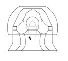
이와 같이 이 발명의 제1 실시예에 따른 트라이포드식 등속조인트의 다면체 트러니언(22)은 외주면이 4개 이상의 면의 조합으로 이루어짐으로써 인너롤러(23)의 내주면과 여러 지점에서 접촉할 수 있는 형상으로 이루어지는데, 도 8a에 도시되어 있는 바와 같이, 임의의 구에 내접하는 다면체로 형성되어 여러 곳에서 점접촉을 하는 형상으로 이루어질 수 있으며, 도 8b에 도시되어 있는 바와 같이 동력 전달부에 속하는 꼭지점만 구에 내접하도록 형성된 다면체로 형성되어 여러 곳에서 점접촉을 하는 형상으로 이루어질 수 있으며, 도 8c에 도시되어 있는 바와 같이 꼭지점에 임의의 곡면으로 가공을 하여 인너롤러(23)의 내주면과 연삭부가 여러 지점에서 면접촉을 하는 형상으로 이루어질 수 있다. As described above, the
상기한 바와 같은 다면체 트러니언(22)을 사용하면 도 9에 도시되어 있는 바와 같이 인너롤러(23)의 내주면과 다수의 접촉부를 가질 수 있기 때문에 동력을 전달함에 있어 안정성을 갖게 되고 한점에 구동력이 집중되어 면압이 상승하는 것을 방지할 수 있으며 면전체가 접촉하여 필요이상의 마찰력을 일으키는 것을 막을 수가 있다. Using the
그리고, 상기한 바와 같은 다면체 트러니언(22)을 사용하면 10a 및 10b에 도시되어 있는 바와 같이 상대운동이 적은 부위에 윤활제의 유입을 원활히 할 수 있도록 화살표로 나타낸 바와 같이 접촉부와 접촉부의 사이에 비접촉 모서리가 확보되어 있어 윤활불량에 의한 내구성 저하를 방지할 수 있다.And, using the
도 11은 이 발명의 제1 실시예에 따른 트라이포드식 등속조인트의 롤러 어셈블리의 폭의 관계를 설명하기 위한 단면도이다. 도 11에 도시되어 있는 바와 같이, 제1 실시예에 따른 트라이포드식 등속조인트의 롤러 어셈블리는, 상기한 인너롤러(23)의 외주면의 한쪽 끝단부에는 니들롤러(24)와 인너롤러(23)의 이탈을 방지하기 위한 리테이너부가 일체형으로 설치되고, 상기한 인너롤러(23)의 외주면의 반대쪽 끝단부에는 니들롤러(24)와 인너롤러(23)가 아우터 롤러(25)의 축방향으로 충분히 움직일 수 있는 거리를 두고 리테이너링(26)과 리테이너 클립(27)이 장착되는 구성으로 이루어진다. 11 is a cross-sectional view for explaining the relationship between the widths of the roller assemblies of the tripod constant velocity joint according to the first embodiment of the present invention. As shown in FIG. 11, the roller assembly of the tripod constant velocity joint according to the first embodiment has a
이 경우에, 상기한 아우터 롤러(25)의 폭(L1)은 니들롤러(24)의 길이(L2)와 L1 < L2/2 의 관계를 유지하고, 아우터 롤러(25)가 인너롤러(23)의 축방향으로 움직일 수 있는 거리(L3)와는 L1 < L3/2의 관계를 유지하는 것이 바람직하다. 이렇게 구성된 롤러 어셈블리(인너롤러(23), 아우터롤러(25), 니들롤러(24), 리테이너링(26), 리테이너클립(27))은 분해될 염려가 없어 취급이 쉬워지고 롤러 어셈블리의 조립성도 용이해진다.In this case, the above-mentioned width of the outer roller 25 (L 1) is maintained a relationship of the length (L 2) and L 1 <L 2/2 of the
도 12는 이 발명의 제1 실시예에 따른 트라이포드식 등속조인트의 다른 롤러 어셈블리의 폭의 관계를 설명하기 위한 단면도이다. 도 12에 도시되어 있는 바와 같이, 제1 실시예에 따른 트라이포드식 등속조인트의 다른 롤러 어셈블리는, 상기한 아우터 롤러(25a)의 내주면의 한쪽 끝단부에는 니들 롤러(24a)와 인너롤러(23a)의 이탈을 방지하기 위한 리테이너부가 일체형으로 설치되고, 상기한 아우터 롤러(25a)의 내주면의 반대쪽 끝단부에는 니들롤러(24a)와 인너롤러(23a)가 아우터 롤러(25a)의 축방향으로 충분히 움직일 수 있는 거리를 두고 리테이너링(26a)과 리테이너 클립(27a)이 장착되는 구성으로 이루어진다. 12 is a cross-sectional view for explaining the relationship between the widths of the other roller assemblies of the tripod constant velocity joint according to the first embodiment of the present invention. As shown in Fig. 12, another roller assembly of the tripod constant velocity joint according to the first embodiment has a
이 경우에, 상기한 인너롤러(23a)의 폭(L4)은 니들롤러(24a)의 길이(L5)와 L4 > L5/2의 관계를 유지하고, 인너롤러(23a)가 아우터롤러(25a)의 축방향으로 움직일 수 있는 거리(L6)와는 L4 > L6/2의 관계를 유지하는 것이 바람직하다. 이렇게 구성된 롤러 어셈블리(인너롤러(23a), 아우터롤러(25a), 니들롤러(24a), 리테이너 링(26a), 리테이너클립(27a))은 분해될 염려가 없어 취급이 쉬워지고 롤러 어셈블리의 조립성도 용이해진다.In this case, the above-mentioned width of the inner roller (23a) (L 4) maintains the relationship of the length (L 5) and L 4> L 5/2 of the needle roller (24a) and an inner roller (23a) has an outer distance movable in the axial direction of the roller (25a) (L 6) than it is desirable to maintain the relation of L 4> L 6/2. The roller assembly (
도 13a는 이 발명의 제2 실시예에 따른 트라이포드식 등속조인트 단면 구성도이고, 도 13b는 이 발명의 제2 실시예에 따른 트라이포드식 등속조인트의 트러니언의 사시 구성도이다.FIG. 13A is a cross-sectional configuration of a tripod constant velocity joint according to a second embodiment of the present invention, and FIG. 13B is a perspective configuration diagram of a trunnion of a tripod constant velocity joint according to a second embodiment of the present invention.
도 13a 및 도 13b에 도시되어 있는 바와 같이, 이 발명의 제2 실시예에 따른 트라이포드식 등속조인트의 구성은, 반경방향으로 3등분된 위치에 축방향으로 형성된 3개의 트랙홈(20b')을 갖는 하우징(20')과, 반경방향으로 3등분된 위치에 편측으로 2개 이상 양측으로 4개 이상의 독립된 접촉점 또는 접촉면을 가지는 형상으로 돌출된 3개의 다면체 트러니온(22')을 가지며 상기한 다면체 트러니언(22')이 상기한 트랙홈(20b')에 삽입되는 스파이더(21')와, 내주면이 다면체 트러니언(22')을 감쌀 수 있는 곡면을 가진 인너롤러(23')와, 상기한 인너롤러(23')의 외주면에 조립된 다수의 니들롤러(24')와, 상기한 니들롤러(24')를 통해 회전이 가능하고 인너롤러(23')의 축방향으로 이동이 가능하며 하우징(20')의 가이드면을 따라 트랙홈(20b')의 축방향으로 이동가능하게 형성되는 아우터 롤러(25')를 포함하여 이루어진다.As shown in Figs. 13A and 13B, the configuration of the tripod constant velocity joint according to the second embodiment of the present invention includes three
도 14는 이 발명의 제2 실시예에 따른 트라이포드식 등속조인트의 다면체 트러니언의 다른 형태를 나타낸 사시도이다.14 is a perspective view showing another form of the polyhedral trunnion of the tripod constant velocity joint according to the second embodiment of the present invention.
이와 같이 이 발명의 제2 실시예에 따른 트라이포드식 등속조인트의 다면체 트러니언(22')은 편측으로 2개이상, 양측으로 4개이상의 독립된 접촉점 또는 접촉 면을 가지도록 외주면이 형성됨으로써 도 15a 및 도 15b에 도시되어 있는 바와 같이 인너롤러(23')의 내주면과 여러 지점에서 접촉할 수 있는 형상으로 이루어진다.As described above, the polyhedral trunnion 22 'of the tripod constant velocity joint according to the second embodiment of the present invention has an outer circumferential surface formed to have two or more independent contact points or contact surfaces on one side and four or more on both sides. And a shape capable of contacting the inner circumferential surface of the inner roller 23 'at various points as shown in FIG. 15B.
상기한 바와 같은 다면체 트러니언(22')을 사용하면 도 16에 도시되어 있는 바와 같이 인너롤러(23')의 내주면과 다수의 접촉부를 가질 수 있기 때문에 동력을 전달함에 있어 안정성을 갖게 되고 한점에 구동력이 집중되어 면압이 상승하는 것을 방지할 수 있으며 면전체가 접촉하여 필요이상의 마찰력을 일으키는 것을 막을 수가 있다. When the polyhedral trunnion 22 'as described above is used, as shown in FIG. 16, since the inner circumferential surface of the inner roller 23' can have a plurality of contacts, stability in transmitting power can be achieved. The driving force is concentrated and the surface pressure can be prevented from rising, and the whole surface can be prevented from contacting and causing more friction than necessary.
그리고, 상기한 바와 같은 다면체 트러니언(22')을 사용하면 17a 및 17b에 도시되어 있는 바와 같이 상대운동이 적은 부위에 윤활제의 유입을 원활히 할 수 있도록 화살표로 나타낸 바와 같이 접촉부와 접촉부의 사이에 비접촉 모서리가 확보되어 있어 윤활불량에 의한 내구성 저하를 방지할 수 있다.And, using the polyhedral trunnion 22 'as described above, as shown by arrows to smoothly inflow of lubricant into the site with less relative movement, as shown in 17a and 17b, as shown by the arrow between the contact portion and the contact portion. Non-contact edges are secured to prevent degradation of durability due to poor lubrication.
도 18은 이 발명의 제2 실시예에 따른 트라이포드식 등속조인트의 롤러 어셈블리의 폭의 관계를 설명하기 위한 단면도이다. 도 18에 도시되어 있는 바와 같이, 제2 실시예에 따른 트라이포드식 등속조인트의 롤러 어셈블리는, 상기한 인너롤러(23')의 외주면의 한쪽 끝단부에는 니들롤러(24')와 인너롤러(23')의 이탈을 방지하기 위한 리테이너부가 일체형으로 설치되고, 상기한 인너롤러(23')의 외주면의 반대쪽 끝단부에는 니들롤러(24')와 인너롤러(23')가 아우터 롤러(25')의 축방향으로 충분히 움직일 수 있는 거리를 두고 리테이너링(26')과 리테이너 클립(27')이 장착되는 구성으로 이루어진다. 18 is a cross-sectional view for explaining the relationship between the widths of the roller assemblies of the tripod constant velocity joint according to the second embodiment of the present invention. As shown in Fig. 18, the roller assembly of the tripod constant velocity joint according to the second embodiment has a needle roller 24 'and an inner roller at one end of the outer circumferential surface of the
이 경우에, 상기한 아우터 롤러(25')의 폭(L1)은 니들롤러(24')의 길이(L2)와 L1 < L2/2 의 관계를 유지하고, 아우터 롤러(25')가 인너롤러(23')의 축방향으로 움직일 수 있는 거리(L3)와는 L1 < L3/2의 관계를 유지하는 것이 바람직하다. 이렇게 구성된 롤러 어셈블리(인너롤러(23'), 아우터롤러(25'), 니들롤러(24'), 리테이너링(26'), 리테이너클립(27'))은 분해될 염려가 없어 취급이 쉬워지고 롤러 어셈블리의 조립성도 용이해진다.In this case, the one outer roller (25 ') the width of the (L 1) is a needle roller (24' maintains the relationship of the length (L 2) and L 1 <L 2/2 in), and the outer roller (25 ' ) it is desirable to maintain a relationship different from L 1 <L 3/2 distance to move in the axial direction of the inner roller (23 ') (L 3) . The roller assembly (inner roller 23 ', outer roller 25', needle roller 24 ', retainer ring 26', retainer clip 27 ') is thus easily handled and disassembled. The assembly of the roller assembly also becomes easy.
도 19는 이 발명의 제2 실시예에 따른 트라이포드식 등속조인트의 다른 롤러 어셈블리의 폭의 관계를 설명하기 위한 단면도이다. 도 19에 도시되어 있는 바와 같이, 제2 실시예에 따른 트라이포드식 등속조인트의 다른 롤러 어셈블리는, 상기한 아우터 롤러(25a')의 내주면의 한쪽 끝단부에는 니들 롤러(24a')와 인너롤러(23a')의 이탈을 방지하기 위한 리테이너부가 일체형으로 설치되고, 상기한 아우터 롤러(25a')의 내주면의 반대쪽 끝단부에는 니들롤러(24a')와 인너롤러(23a')가 아우터 롤러(25a')의 축방향으로 충분히 움직일 수 있는 거리를 두고 리테이너링(26a')과 리테이너 클립(27a')이 장착되는 구성으로 이루어진다. 19 is a cross-sectional view for explaining the relationship between the widths of the other roller assemblies of the tripod constant velocity joint according to the second embodiment of the present invention. As shown in Fig. 19, another roller assembly of the tripod constant velocity joint according to the second embodiment has a
이 경우에, 상기한 인너롤러(23a')의 폭(L4)은 니들롤러(24a')의 길이(L5)와 L4 > L5/2의 관계를 유지하고, 인너롤러(23a')가 아우터롤러(25a')의 축방향으로 움직일 수 있는 거리(L6)와는 L4 > L6/2의 관계를 유지하는 것이 바람직하다. 이렇게 구성된 롤러 어셈블리(인너롤러(23a'), 아우터롤러(25a'), 니들롤러(24a'), 리테이 너링(26a'), 리테이너클립(27a'))은 분해될 염려가 없어 취급이 쉬워지고 롤러 어셈블리의 조립성도 용이해진다.In this case, the above-described inner roller (23a '), a width of (L 4) is a needle roller (24a' maintains the relationship of the length (L 5) and L 4> L 5/2 in) and an inner roller (23a ' ) is preferably different from that maintains the relationship of L 4> L 6/2 distance (L 6) that can move in the axial direction of the outer roller (25a '). The roller assembly (
도 20a는 이 발명의 제3 실시예에 따른 트라이포드식 등속조인트 단면 구성도이고, 도 20b는 이 발명의 제3 실시예에 따른 트라이포드식 등속조인트의 트러니언의 사시 구성도이다.20A is a cross-sectional configuration of a tripod constant velocity joint according to a third embodiment of the present invention, and FIG. 20B is a perspective configuration diagram of a trunnion of a tripod constant velocity joint according to a third embodiment of the present invention.
도 20a 및 도 20b에 도시되어 있는 바와 같이, 이 발명의 제3 실시예에 따른 트라이포드식 등속조인트의 구성은, 반경방향으로 3등분된 위치에 축방향으로 형성된 3개의 트랙홈(20b")을 갖는 하우징(20")과, 반경방향으로 3등분된 위치에 1개 이상의 독립된 접촉면이 양측에 각각 위치하도록 4개 이상의 면을 가지는 형상으로 돌출된 3개의 다면체 트러니온(22")을 가지며 상기한 다면체 트러니언(22")이 상기한 트랙홈(20b")에 삽입되는 스파이더(21")와, 내주면이 다면체 트러니언(22")을 감쌀 수 있는 곡면을 가진 인너롤러(23")와, 상기한 인너롤러(23")의 외주면에 조립된 다수의 니들롤러(24")와, 상기한 니들롤러(24")를 통해 회전이 가능하고 인너롤러(23")의 축방향으로 이동이 가능하며 하우징(20")의 가이드면을 따라 트랙홈(20b")의 축방향으로 이동가능하게 형성되는 아우터 롤러(25")와, 상기한 인너롤러(23")의 이탈을 방지하기 위한 설치되는 리테이너(26") 및 리테이너 클립(27")을 포함하여 이루어진다. As shown in Figs. 20A and 20B, the configuration of the tripod constant velocity joint according to the third embodiment of the present invention includes three
도 21a 및 도 21b에 도시되어 있는 바와 같이 이 발명의 제3 실시예에 따른 트라이포드식 등속조인트의 다면체 트러니언(22")은 1개 이상의 독립된 접촉면이 양측에 각각 위치하도록 4개 이상의 면으로 구성된 외주면이 형성됨으로써 임의의 면의 모서리를 따라 연속적인 접촉면 또는 2개 이상의 비연속적인 접촉면이 넓게 배치됨과 동시에 접촉면이 형성되는 면의 모서리중 적어도 하나의 모서리는 비접촉부로 유지되어서 인너롤러 내주면과의 틈새를 유지하는 형상으로 이루어진다.As shown in Figs. 21A and 21B, the
상기한 바와 같은 다면체 트러니언(22")을 사용하면 도 22에 도시되어 있는 바와 같이 인너롤러(23")의 내주면과 다수의 접촉부를 가질 수 있기 때문에 동력을 전달함에 있어 안정성을 갖게 되고 한점에 구동력이 집중되어 면압이 상승하는 것을 방지할 수 있으며 면전체가 접촉하여 필요이상의 마찰력을 일으키는 것을 막을 수가 있다. When the
그리고, 상기한 바와 같은 다면체 트러니언(22")을 사용하면 23a 및 23b에 도시되어 있는 바와 같이 상대운동이 적은 부위에 윤활제의 유입을 원활히 할 수 있도록 화살표로 나타낸 바와 같이 접촉부와 접촉부의 사이에 적어도 하나의 모서리는 비접촉부로 유지되어 인너롤러(23")의 내주면과의 틈새를 유지함으로써 윤활불량에 의한 내구성 저하를 방지할 수 있다.And, using the
도 24는 이 발명의 제3 실시예에 따른 트라이포드식 등속조인트의 롤러 어셈블리의 폭의 관계를 설명하기 위한 단면도이다. 도 24에 도시되어 있는 바와 같이, 제2 실시예에 따른 트라이포드식 등속조인트의 롤러 어셈블리는, 상기한 인너롤러(23")의 외주면의 한쪽 끝단부에는 니들롤러(24")와 인너롤러(23")의 이탈을 방지하기 위한 리테이너부가 일체형으로 설치되고, 상기한 인너롤러(23")의 외주면의 반대쪽 끝단부에는 니들롤러(24")와 인너롤러(23")가 아우터 롤러(25")의 축방향으로 충분히 움직일 수 있는 거리를 두고 리테이너링(26")과 리테이너 클립(27")이 장착되는 구성으로 이루어진다. 24 is a cross-sectional view for explaining the relationship between the widths of the roller assemblies of the tripod constant velocity joint according to the third embodiment of the present invention. As shown in Fig. 24, the roller assembly of the tripod constant velocity joint according to the second embodiment has a
이 경우에, 상기한 아우터 롤러(25")의 폭(L1)은 니들롤러(24")의 길이(L2)와 L1 < L2/2 의 관계를 유지하고, 아우터 롤러(25")가 인너롤러(23")의 축방향으로 움직일 수 있는 거리(L3)와는 L1 < L3/2의 관계를 유지하는 것이 바람직하다. 이렇게 구성된 롤러 어셈블리(인너롤러(23"), 아우터롤러(25"), 니들롤러(24"), 리테이너링(26"), 리테이너클립(27"))은 분해될 염려가 없어 취급이 쉬워지고 롤러 어셈블리의 조립성도 용이해진다.In this case, the one outer roller (25 ") width (L 1) is a needle roller (24 'maintains the relationship of the length (L 2) and L 1 <L 2/2 in), and the outer roller (25" ) is preferably different from that held the relationship L 1 <L 3/2 distance to move in the axial direction of the inner roller (23 ") (L 3) . The roller assembly (
도 25는 이 발명의 제3 실시예에 따른 트라이포드식 등속조인트의 다른 롤러 어셈블리의 폭의 관계를 설명하기 위한 단면도이다. 도 25에 도시되어 있는 바와 같이, 제2 실시예에 따른 트라이포드식 등속조인트의 다른 롤러 어셈블리는, 상기한 아우터 롤러(25a")의 내주면의 한쪽 끝단부에는 니들 롤러(24a")와 인너롤러(23a")의 이탈을 방지하기 위한 리테이너부가 일체형으로 설치되고, 상기한 아우터 롤러(25a")의 내주면의 반대쪽 끝단부에는 니들롤러(24a")와 인너롤러(23a")가 아우터 롤러(25a")의 축방향으로 충분히 움직일 수 있는 거리를 두고 리테이너링(26a")과 리테이너 클립(27a")이 장착되는 구성으로 이루어진다. 25 is a cross-sectional view for explaining the relationship between the widths of the other roller assemblies of the tripod constant velocity joint according to the third embodiment of the present invention. As shown in Fig. 25, another roller assembly of the tripod constant velocity joint according to the second embodiment has a
이 경우에, 상기한 인너롤러(23a")의 폭(L4)은 니들롤러(24a")의 길이(L5)와 L4 > L5/2의 관계를 유지하고, 인너롤러(23a")가 아우터롤러(25a")의 축방향으로 움직일 수 있는 거리(L6)와는 L4 > L6/2의 관계를 유지하는 것이 바람직하다. 이렇게 구성된 롤러 어셈블리(인너롤러(23a"), 아우터롤러(25a"), 니들롤러(24a"), 리테이너링(26a"), 리테이너클립(27a"))은 분해될 염려가 없어 취급이 쉬워지고 롤러 어셈블리의 조립성도 용이해진다.In this case, the above-described inner roller (23a ") the width of the (L 4) is a needle roller (24a" maintaining the relationship between the length (L 5) and L 4> L 5/2 in) and an inner roller (23a " ) is preferably different from that maintains the relationship of L 4> L 6/2 distance (L 6) that can move in the axial direction of the outer roller (25a "). The roller assembly (
이상의 실시예에서 살펴 본 바와 같이 이 발명은, 2개 이상의 다각형 평면을 갖는 다면체 트러니언을 이용하여 인너롤러의 내주면과 다수의 접촉부를 가질 수 있도록 함으로써 동력을 전달함에 있어 안정성을 갖게 되고, 한점에 구동력이 집중되어 면압이 상승하는 것을 방지할 수 있으며, 면전체가 접촉하여 필요이상의 마찰력을 일으키는 것을 막음과 동시에, 상대 운동이 적은 부분에는 다면체 트러니언의 직선부를 이용하여 원활한 윤활이 이루어지도록 하여 마찰력을 줄임으로써 축방향의 힘을 억제하여 차량의 진동을 저감시키고 내구성을 향상시킬 수 있는, 효과를 갖는다.As described in the above embodiment, the present invention, by using a polyhedron trunnion having two or more polygonal planes to have a plurality of contacts with the inner circumferential surface of the inner roller has a stability in transmitting power, at one point The driving force is concentrated and the surface pressure rises can be prevented, and the entire surface is prevented from contacting and causing more frictional force, and the frictional force can be smoothly lubricated by using the linear part of the polyhedral trunnion in the part with less relative movement By reducing the pressure, the axial force can be suppressed to reduce vibration of the vehicle and improve durability.
Claims (15)
Priority Applications (7)
| Application Number | Priority Date | Filing Date | Title |
|---|---|---|---|
| KR1020060042572A KR100815677B1 (en) | 2006-05-11 | 2006-05-11 | tripod type constant velocity joint |
| PCT/KR2006/002513 WO2007132963A1 (en) | 2006-05-11 | 2006-06-28 | Tripod type constant velocity joint |
| CNB2006800106457A CN100557258C (en) | 2006-05-11 | 2006-06-28 | Tripod type constant velocity joint |
| DE112006000703.3T DE112006000703B4 (en) | 2006-05-11 | 2006-06-28 | Tripod constant velocity joint |
| JP2008515632A JP4763048B2 (en) | 2006-05-11 | 2006-06-28 | Tripod constant velocity joint |
| US11/927,601 US7874924B2 (en) | 2006-05-11 | 2007-10-29 | Tripod type constant velocity joint |
| US12/978,238 US8298092B2 (en) | 2006-05-11 | 2010-12-23 | Tripod type constant velocity joint |
Applications Claiming Priority (1)
| Application Number | Priority Date | Filing Date | Title |
|---|---|---|---|
| KR1020060042572A KR100815677B1 (en) | 2006-05-11 | 2006-05-11 | tripod type constant velocity joint |
Publications (2)
| Publication Number | Publication Date |
|---|---|
| KR20070109511A true KR20070109511A (en) | 2007-11-15 |
| KR100815677B1 KR100815677B1 (en) | 2008-03-20 |
Family
ID=38694042
Family Applications (1)
| Application Number | Title | Priority Date | Filing Date |
|---|---|---|---|
| KR1020060042572A KR100815677B1 (en) | 2006-05-11 | 2006-05-11 | tripod type constant velocity joint |
Country Status (6)
| Country | Link |
|---|---|
| US (2) | US7874924B2 (en) |
| JP (1) | JP4763048B2 (en) |
| KR (1) | KR100815677B1 (en) |
| CN (1) | CN100557258C (en) |
| DE (1) | DE112006000703B4 (en) |
| WO (1) | WO2007132963A1 (en) |
Families Citing this family (12)
| Publication number | Priority date | Publication date | Assignee | Title |
|---|---|---|---|---|
| FR2907178B1 (en) * | 2006-10-12 | 2009-07-10 | Gkn Driveline Sa Sa | HOMOCINETIC JOINT |
| CN101836000B (en) * | 2007-10-23 | 2014-07-09 | Gkn动力传动系统国际有限责任公司 | Tripod joint and roller body for a tripod joint |
| US8251827B2 (en) * | 2007-11-29 | 2012-08-28 | Hyundai Wia Corporation | Constant velocity joint of tripod type |
| JP5377908B2 (en) * | 2008-08-28 | 2013-12-25 | Ntn株式会社 | Manufacturing method of tripod type constant velocity universal joint |
| DE102009000561A1 (en) * | 2009-02-02 | 2010-08-05 | Tedrive Holding B.V. | Constant velocity joint with improved mounting properties |
| DE102009000560A1 (en) * | 2009-02-02 | 2010-08-05 | Tedrive Holding B.V. | Constant velocity joint with improved mounting properties |
| JP5323572B2 (en) * | 2009-04-20 | 2013-10-23 | Ntn株式会社 | Tripod type constant velocity universal joint and manufacturing method thereof |
| CN103335028A (en) * | 2013-05-31 | 2013-10-02 | 浙江嘉盛汽车部件制造有限公司 | Three-ball pin assembly |
| US10174793B2 (en) | 2013-10-30 | 2019-01-08 | Steering Solutions Ip Holding Corporation | Tripot constant velocity joint |
| EP3015730B1 (en) * | 2014-10-30 | 2021-01-20 | Steering Solutions IP Holding Corporation | Tripot constant velocity joint |
| CN105570328A (en) * | 2014-10-30 | 2016-05-11 | 操纵技术Ip控股公司 | Tripot constant velocity joint |
| DE102020212991A1 (en) * | 2020-10-14 | 2022-04-14 | Volkswagen Aktiengesellschaft | Tripod joint and method for its manufacture |
Family Cites Families (19)
| Publication number | Priority date | Publication date | Assignee | Title |
|---|---|---|---|---|
| US3490251A (en) * | 1968-09-18 | 1970-01-20 | Gen Motors Corp | Pot type universal joint |
| JPS61157829A (en) * | 1984-12-28 | 1986-07-17 | Nissan Motor Co Ltd | Manufacture of housing of uniform speed joint |
| GB8829530D0 (en) * | 1988-12-17 | 1989-02-01 | Spicer Hardy Ltd | Constant velocity ratio universal joints |
| US5348512A (en) * | 1992-11-12 | 1994-09-20 | Ina Bearing Company, Inc. | Friction reduced constant velocity universal joint |
| DE4331108C1 (en) * | 1993-09-15 | 1995-01-05 | Gkn Automotive Ag | Homokinetic joint |
| DE4305278C1 (en) * | 1993-02-20 | 1994-07-28 | Gkn Automotive Ag | Tripod type constant velocity universal joint |
| JPH09151952A (en) * | 1995-11-30 | 1997-06-10 | Ntn Corp | Trunnion member for triboard type constant velocity universal joint |
| DE69737661T2 (en) * | 1996-02-05 | 2008-01-03 | Ntn Corp. | Constant velocity universal joint with three pins |
| JP3917227B2 (en) * | 1996-12-26 | 2007-05-23 | Ntn株式会社 | Tripod type constant velocity universal joint |
| JP3043280B2 (en) * | 1996-02-15 | 2000-05-22 | 本田技研工業株式会社 | Constant velocity joint |
| JPH11336784A (en) * | 1998-05-22 | 1999-12-07 | Toyota Motor Corp | Universal uniform coupling |
| JP4334754B2 (en) * | 2000-10-13 | 2009-09-30 | デルファイ・テクノロジーズ・インコーポレーテッド | Tripod type constant velocity joint |
| JP2002213478A (en) * | 2001-01-19 | 2002-07-31 | Honda Motor Co Ltd | Constant velocity universal joint |
| TWI298767B (en) * | 2002-10-25 | 2008-07-11 | Ntn Toyo Bearing Co Ltd | Tripod type constant velocity joint |
| JP4255678B2 (en) | 2002-11-12 | 2009-04-15 | Ntn株式会社 | Tripod type constant velocity universal joint |
| JP2004144240A (en) * | 2002-10-25 | 2004-05-20 | Ntn Corp | Tripod type constant velocity universal joint |
| DE10325116A1 (en) * | 2003-06-02 | 2005-01-13 | Visteon Global Technologies, Inc., Dearborn | Synchronous rotating joint with three tracks and pivots has inner ring forming axial guide and fixing position of rolling bodies relative to inner ring in axial direction |
| KR100614001B1 (en) * | 2005-03-10 | 2006-08-21 | 한국프랜지공업 주식회사 | Tripod constant velocity joint structure |
| JP4541203B2 (en) * | 2005-03-24 | 2010-09-08 | Ntn株式会社 | Tripod type constant velocity universal joint |
-
2006
- 2006-05-11 KR KR1020060042572A patent/KR100815677B1/en active IP Right Grant
- 2006-06-28 JP JP2008515632A patent/JP4763048B2/en active Active
- 2006-06-28 CN CNB2006800106457A patent/CN100557258C/en active Active
- 2006-06-28 WO PCT/KR2006/002513 patent/WO2007132963A1/en active Application Filing
- 2006-06-28 DE DE112006000703.3T patent/DE112006000703B4/en active Active
-
2007
- 2007-10-29 US US11/927,601 patent/US7874924B2/en active Active
-
2010
- 2010-12-23 US US12/978,238 patent/US8298092B2/en active Active
Also Published As
| Publication number | Publication date |
|---|---|
| US20110159969A1 (en) | 2011-06-30 |
| DE112006000703B4 (en) | 2016-10-06 |
| DE112006000703T5 (en) | 2009-10-15 |
| US20080058107A1 (en) | 2008-03-06 |
| WO2007132963A1 (en) | 2007-11-22 |
| JP2008523341A (en) | 2008-07-03 |
| US7874924B2 (en) | 2011-01-25 |
| KR100815677B1 (en) | 2008-03-20 |
| US8298092B2 (en) | 2012-10-30 |
| JP4763048B2 (en) | 2011-08-31 |
| CN100557258C (en) | 2009-11-04 |
| CN101189442A (en) | 2008-05-28 |
Similar Documents
| Publication | Publication Date | Title |
|---|---|---|
| KR100815677B1 (en) | tripod type constant velocity joint | |
| JP4781591B2 (en) | Tripod type constant velocity joint | |
| US8894497B2 (en) | Sliding ball type constant velocity joint for vehicle | |
| JP4198995B2 (en) | Constant velocity joint and its mechanical transmission member | |
| KR100614001B1 (en) | Tripod constant velocity joint structure | |
| KR20110021221A (en) | Shudderless in board type of constant velocity joint | |
| JP4147179B2 (en) | Constant velocity universal joint | |
| KR101203767B1 (en) | tripod type constant velocity joint | |
| KR100834215B1 (en) | tripod type constant velocity joint | |
| KR20150049182A (en) | Tripod type constant velocity joint | |
| JP2012013207A (en) | Tripod type constant velocity joint | |
| CN213929211U (en) | Three-pin joint type constant-speed driving shaft | |
| JP4898380B2 (en) | Flat belt idler pulley device | |
| JPH08145071A (en) | Tripod type constant velocity joint | |
| JP3976358B2 (en) | Tripod type constant velocity joint | |
| KR100706081B1 (en) | Structure for tripod constant velocity joint | |
| RU121019U1 (en) | CONSTANT-VELOCITY JOINT | |
| KR100706080B1 (en) | Structure for tripod constant velocity joint with ball bearing | |
| KR20060060342A (en) | Tripod constant velocity joint | |
| KR100834214B1 (en) | tripod type constant velocity joint | |
| KR20190110770A (en) | Tripod type constant velocity joint for vehicle | |
| KR20220099762A (en) | Constant velocity joint | |
| KR20200029694A (en) | Tripod type Constant Velocity Joint | |
| JP2006138421A (en) | Tripod type constant velocity universal joint | |
| JP2006266328A (en) | Constant velocity universal joint |
Legal Events
| Date | Code | Title | Description |
|---|---|---|---|
| A201 | Request for examination | ||
| E902 | Notification of reason for refusal | ||
| E902 | Notification of reason for refusal | ||
| E701 | Decision to grant or registration of patent right | ||
| GRNT | Written decision to grant | ||
| FPAY | Annual fee payment |
Payment date: 20130308 Year of fee payment: 6 |
|
| FPAY | Annual fee payment |
Payment date: 20140313 Year of fee payment: 7 |
|
| FPAY | Annual fee payment |
Payment date: 20150312 Year of fee payment: 8 |
|
| FPAY | Annual fee payment |
Payment date: 20170220 Year of fee payment: 10 |
|
| FPAY | Annual fee payment |
Payment date: 20180208 Year of fee payment: 11 |
|
| FPAY | Annual fee payment |
Payment date: 20190212 Year of fee payment: 12 |
|
| FPAY | Annual fee payment |
Payment date: 20200211 Year of fee payment: 13 |