KR20060123189A - Connection between a pipe and a wall - Google Patents
Connection between a pipe and a wall Download PDFInfo
- Publication number
- KR20060123189A KR20060123189A KR1020067010066A KR20067010066A KR20060123189A KR 20060123189 A KR20060123189 A KR 20060123189A KR 1020067010066 A KR1020067010066 A KR 1020067010066A KR 20067010066 A KR20067010066 A KR 20067010066A KR 20060123189 A KR20060123189 A KR 20060123189A
- Authority
- KR
- South Korea
- Prior art keywords
- connector
- flange
- pipe
- wall
- chamber
- Prior art date
Links
Images


Classifications
-
- F—MECHANICAL ENGINEERING; LIGHTING; HEATING; WEAPONS; BLASTING
- F16—ENGINEERING ELEMENTS AND UNITS; GENERAL MEASURES FOR PRODUCING AND MAINTAINING EFFECTIVE FUNCTIONING OF MACHINES OR INSTALLATIONS; THERMAL INSULATION IN GENERAL
- F16L—PIPES; JOINTS OR FITTINGS FOR PIPES; SUPPORTS FOR PIPES, CABLES OR PROTECTIVE TUBING; MEANS FOR THERMAL INSULATION IN GENERAL
- F16L5/00—Devices for use where pipes, cables or protective tubing pass through walls or partitions
- F16L5/02—Sealing
-
- F—MECHANICAL ENGINEERING; LIGHTING; HEATING; WEAPONS; BLASTING
- F16—ENGINEERING ELEMENTS AND UNITS; GENERAL MEASURES FOR PRODUCING AND MAINTAINING EFFECTIVE FUNCTIONING OF MACHINES OR INSTALLATIONS; THERMAL INSULATION IN GENERAL
- F16L—PIPES; JOINTS OR FITTINGS FOR PIPES; SUPPORTS FOR PIPES, CABLES OR PROTECTIVE TUBING; MEANS FOR THERMAL INSULATION IN GENERAL
- F16L47/00—Connecting arrangements or other fittings specially adapted to be made of plastics or to be used with pipes made of plastics
- F16L47/20—Connecting arrangements or other fittings specially adapted to be made of plastics or to be used with pipes made of plastics based principally on specific properties of plastics
- F16L47/24—Connecting arrangements or other fittings specially adapted to be made of plastics or to be used with pipes made of plastics based principally on specific properties of plastics for joints between metal and plastics pipes
-
- B—PERFORMING OPERATIONS; TRANSPORTING
- B67—OPENING, CLOSING OR CLEANING BOTTLES, JARS OR SIMILAR CONTAINERS; LIQUID HANDLING
- B67D—DISPENSING, DELIVERING OR TRANSFERRING LIQUIDS, NOT OTHERWISE PROVIDED FOR
- B67D7/00—Apparatus or devices for transferring liquids from bulk storage containers or reservoirs into vehicles or into portable containers, e.g. for retail sale purposes
- B67D7/04—Apparatus or devices for transferring liquids from bulk storage containers or reservoirs into vehicles or into portable containers, e.g. for retail sale purposes for transferring fuels, lubricants or mixed fuels and lubricants
-
- F—MECHANICAL ENGINEERING; LIGHTING; HEATING; WEAPONS; BLASTING
- F16—ENGINEERING ELEMENTS AND UNITS; GENERAL MEASURES FOR PRODUCING AND MAINTAINING EFFECTIVE FUNCTIONING OF MACHINES OR INSTALLATIONS; THERMAL INSULATION IN GENERAL
- F16L—PIPES; JOINTS OR FITTINGS FOR PIPES; SUPPORTS FOR PIPES, CABLES OR PROTECTIVE TUBING; MEANS FOR THERMAL INSULATION IN GENERAL
- F16L47/00—Connecting arrangements or other fittings specially adapted to be made of plastics or to be used with pipes made of plastics
- F16L47/02—Welded joints; Adhesive joints
- F16L47/03—Welded joints with an electrical resistance incorporated in the joint
-
- F—MECHANICAL ENGINEERING; LIGHTING; HEATING; WEAPONS; BLASTING
- F16—ENGINEERING ELEMENTS AND UNITS; GENERAL MEASURES FOR PRODUCING AND MAINTAINING EFFECTIVE FUNCTIONING OF MACHINES OR INSTALLATIONS; THERMAL INSULATION IN GENERAL
- F16L—PIPES; JOINTS OR FITTINGS FOR PIPES; SUPPORTS FOR PIPES, CABLES OR PROTECTIVE TUBING; MEANS FOR THERMAL INSULATION IN GENERAL
- F16L5/00—Devices for use where pipes, cables or protective tubing pass through walls or partitions
- F16L5/02—Sealing
- F16L5/022—Sealing by welding
-
- F—MECHANICAL ENGINEERING; LIGHTING; HEATING; WEAPONS; BLASTING
- F16—ENGINEERING ELEMENTS AND UNITS; GENERAL MEASURES FOR PRODUCING AND MAINTAINING EFFECTIVE FUNCTIONING OF MACHINES OR INSTALLATIONS; THERMAL INSULATION IN GENERAL
- F16L—PIPES; JOINTS OR FITTINGS FOR PIPES; SUPPORTS FOR PIPES, CABLES OR PROTECTIVE TUBING; MEANS FOR THERMAL INSULATION IN GENERAL
- F16L5/00—Devices for use where pipes, cables or protective tubing pass through walls or partitions
- F16L5/02—Sealing
- F16L5/06—Sealing by means of a swivel nut compressing a ring or sleeve
-
- F—MECHANICAL ENGINEERING; LIGHTING; HEATING; WEAPONS; BLASTING
- F16—ENGINEERING ELEMENTS AND UNITS; GENERAL MEASURES FOR PRODUCING AND MAINTAINING EFFECTIVE FUNCTIONING OF MACHINES OR INSTALLATIONS; THERMAL INSULATION IN GENERAL
- F16L—PIPES; JOINTS OR FITTINGS FOR PIPES; SUPPORTS FOR PIPES, CABLES OR PROTECTIVE TUBING; MEANS FOR THERMAL INSULATION IN GENERAL
- F16L5/00—Devices for use where pipes, cables or protective tubing pass through walls or partitions
- F16L5/02—Sealing
- F16L5/14—Sealing for double-walled or multi-channel pipes
-
- B—PERFORMING OPERATIONS; TRANSPORTING
- B29—WORKING OF PLASTICS; WORKING OF SUBSTANCES IN A PLASTIC STATE IN GENERAL
- B29C—SHAPING OR JOINING OF PLASTICS; SHAPING OF MATERIAL IN A PLASTIC STATE, NOT OTHERWISE PROVIDED FOR; AFTER-TREATMENT OF THE SHAPED PRODUCTS, e.g. REPAIRING
- B29C66/00—General aspects of processes or apparatus for joining preformed parts
- B29C66/70—General aspects of processes or apparatus for joining preformed parts characterised by the composition, physical properties or the structure of the material of the parts to be joined; Joining with non-plastics material
- B29C66/72—General aspects of processes or apparatus for joining preformed parts characterised by the composition, physical properties or the structure of the material of the parts to be joined; Joining with non-plastics material characterised by the structure of the material of the parts to be joined
- B29C66/721—Fibre-reinforced materials
-
- B—PERFORMING OPERATIONS; TRANSPORTING
- B29—WORKING OF PLASTICS; WORKING OF SUBSTANCES IN A PLASTIC STATE IN GENERAL
- B29K—INDEXING SCHEME ASSOCIATED WITH SUBCLASSES B29B, B29C OR B29D, RELATING TO MOULDING MATERIALS OR TO MATERIALS FOR MOULDS, REINFORCEMENTS, FILLERS OR PREFORMED PARTS, e.g. INSERTS
- B29K2023/00—Use of polyalkenes or derivatives thereof as moulding material
- B29K2023/04—Polymers of ethylene
- B29K2023/06—PE, i.e. polyethylene
-
- B—PERFORMING OPERATIONS; TRANSPORTING
- B29—WORKING OF PLASTICS; WORKING OF SUBSTANCES IN A PLASTIC STATE IN GENERAL
- B29K—INDEXING SCHEME ASSOCIATED WITH SUBCLASSES B29B, B29C OR B29D, RELATING TO MOULDING MATERIALS OR TO MATERIALS FOR MOULDS, REINFORCEMENTS, FILLERS OR PREFORMED PARTS, e.g. INSERTS
- B29K2023/00—Use of polyalkenes or derivatives thereof as moulding material
- B29K2023/10—Polymers of propylene
- B29K2023/12—PP, i.e. polypropylene
-
- B—PERFORMING OPERATIONS; TRANSPORTING
- B29—WORKING OF PLASTICS; WORKING OF SUBSTANCES IN A PLASTIC STATE IN GENERAL
- B29K—INDEXING SCHEME ASSOCIATED WITH SUBCLASSES B29B, B29C OR B29D, RELATING TO MOULDING MATERIALS OR TO MATERIALS FOR MOULDS, REINFORCEMENTS, FILLERS OR PREFORMED PARTS, e.g. INSERTS
- B29K2027/00—Use of polyvinylhalogenides or derivatives thereof as moulding material
- B29K2027/06—PVC, i.e. polyvinylchloride
-
- B—PERFORMING OPERATIONS; TRANSPORTING
- B29—WORKING OF PLASTICS; WORKING OF SUBSTANCES IN A PLASTIC STATE IN GENERAL
- B29K—INDEXING SCHEME ASSOCIATED WITH SUBCLASSES B29B, B29C OR B29D, RELATING TO MOULDING MATERIALS OR TO MATERIALS FOR MOULDS, REINFORCEMENTS, FILLERS OR PREFORMED PARTS, e.g. INSERTS
- B29K2027/00—Use of polyvinylhalogenides or derivatives thereof as moulding material
- B29K2027/12—Use of polyvinylhalogenides or derivatives thereof as moulding material containing fluorine
- B29K2027/14—PVF, i.e. polyvinyl fluoride
-
- B—PERFORMING OPERATIONS; TRANSPORTING
- B29—WORKING OF PLASTICS; WORKING OF SUBSTANCES IN A PLASTIC STATE IN GENERAL
- B29K—INDEXING SCHEME ASSOCIATED WITH SUBCLASSES B29B, B29C OR B29D, RELATING TO MOULDING MATERIALS OR TO MATERIALS FOR MOULDS, REINFORCEMENTS, FILLERS OR PREFORMED PARTS, e.g. INSERTS
- B29K2027/00—Use of polyvinylhalogenides or derivatives thereof as moulding material
- B29K2027/12—Use of polyvinylhalogenides or derivatives thereof as moulding material containing fluorine
- B29K2027/16—PVDF, i.e. polyvinylidene fluoride
-
- B—PERFORMING OPERATIONS; TRANSPORTING
- B29—WORKING OF PLASTICS; WORKING OF SUBSTANCES IN A PLASTIC STATE IN GENERAL
- B29K—INDEXING SCHEME ASSOCIATED WITH SUBCLASSES B29B, B29C OR B29D, RELATING TO MOULDING MATERIALS OR TO MATERIALS FOR MOULDS, REINFORCEMENTS, FILLERS OR PREFORMED PARTS, e.g. INSERTS
- B29K2027/00—Use of polyvinylhalogenides or derivatives thereof as moulding material
- B29K2027/12—Use of polyvinylhalogenides or derivatives thereof as moulding material containing fluorine
- B29K2027/18—PTFE, i.e. polytetrafluorethene, e.g. ePTFE, i.e. expanded polytetrafluorethene
-
- B—PERFORMING OPERATIONS; TRANSPORTING
- B29—WORKING OF PLASTICS; WORKING OF SUBSTANCES IN A PLASTIC STATE IN GENERAL
- B29K—INDEXING SCHEME ASSOCIATED WITH SUBCLASSES B29B, B29C OR B29D, RELATING TO MOULDING MATERIALS OR TO MATERIALS FOR MOULDS, REINFORCEMENTS, FILLERS OR PREFORMED PARTS, e.g. INSERTS
- B29K2059/00—Use of polyacetals, e.g. POM, i.e. polyoxymethylene or derivatives thereof, as moulding material
-
- B—PERFORMING OPERATIONS; TRANSPORTING
- B29—WORKING OF PLASTICS; WORKING OF SUBSTANCES IN A PLASTIC STATE IN GENERAL
- B29K—INDEXING SCHEME ASSOCIATED WITH SUBCLASSES B29B, B29C OR B29D, RELATING TO MOULDING MATERIALS OR TO MATERIALS FOR MOULDS, REINFORCEMENTS, FILLERS OR PREFORMED PARTS, e.g. INSERTS
- B29K2067/00—Use of polyesters or derivatives thereof, as moulding material
- B29K2067/006—PBT, i.e. polybutylene terephthalate
-
- B—PERFORMING OPERATIONS; TRANSPORTING
- B29—WORKING OF PLASTICS; WORKING OF SUBSTANCES IN A PLASTIC STATE IN GENERAL
- B29K—INDEXING SCHEME ASSOCIATED WITH SUBCLASSES B29B, B29C OR B29D, RELATING TO MOULDING MATERIALS OR TO MATERIALS FOR MOULDS, REINFORCEMENTS, FILLERS OR PREFORMED PARTS, e.g. INSERTS
- B29K2075/00—Use of PU, i.e. polyureas or polyurethanes or derivatives thereof, as moulding material
-
- B—PERFORMING OPERATIONS; TRANSPORTING
- B29—WORKING OF PLASTICS; WORKING OF SUBSTANCES IN A PLASTIC STATE IN GENERAL
- B29K—INDEXING SCHEME ASSOCIATED WITH SUBCLASSES B29B, B29C OR B29D, RELATING TO MOULDING MATERIALS OR TO MATERIALS FOR MOULDS, REINFORCEMENTS, FILLERS OR PREFORMED PARTS, e.g. INSERTS
- B29K2077/00—Use of PA, i.e. polyamides, e.g. polyesteramides or derivatives thereof, as moulding material
-
- B—PERFORMING OPERATIONS; TRANSPORTING
- B29—WORKING OF PLASTICS; WORKING OF SUBSTANCES IN A PLASTIC STATE IN GENERAL
- B29K—INDEXING SCHEME ASSOCIATED WITH SUBCLASSES B29B, B29C OR B29D, RELATING TO MOULDING MATERIALS OR TO MATERIALS FOR MOULDS, REINFORCEMENTS, FILLERS OR PREFORMED PARTS, e.g. INSERTS
- B29K2309/00—Use of inorganic materials not provided for in groups B29K2303/00 - B29K2307/00, as reinforcement
- B29K2309/08—Glass
Abstract
Description
본 발명은 벽과 이러한 벽의 개구를 관통하는 파이프 사이에 밀봉체를 제공하는 연결구(fitting)와, 이러한 밀봉체를 제공하는 방법과, 파이프, 벽 및 이 둘 사이에 밀봉체를 제공하는 연결구의 조합을 포함하는 조립체에 관한 것이다. 특히, 본 발명은 예를 들어 주유소 설비에서 그리고 특히 챔버 또는 섬프(sump)의 벽이 유리 강화 플라스틱(GRP)으로 제조된 경우에, 지하 연료 탱크에서 발견되는 것과 같은 맨홀 챔버의 벽과 파이프 사이에, 또는 분배 펌프용 섬프의 벽과 파이프 사이에 밀봉체를 제공하는 데 적용될 수 있다. The present invention provides a fitting for providing a seal between a wall and a pipe passing through the opening of the wall, a method for providing such a seal, and a pipe, a wall and a connector for providing a seal between the two. An assembly comprising a combination. In particular, the present invention provides for example between a pipe and a wall of a manhole chamber as found in underground fuel tanks, for example in gas station installations and in particular when the walls of the chamber or sump are made of glass reinforced plastic (GRP). Or, to provide a seal between the pipe and the wall of the sump for the dispensing pump.
통상 주유소(service station)에 설치되는 유형의 지하 배관 시스템은 일반적으로 지하 저장 탱크와 지상 분배 스테이션 사이에 연료 또는 화학물질을 연통시키는데 이용된다. 지하 저장 탱크와, 관련 배관은 내장된 화학물질이 과거에 땅속으로 누출될 수 있거나 누출됨에 따라, 심각한 환경 및 화재 위험 요소를 불러일으킨다.Underground plumbing systems of the type typically installed at service stations are generally used to communicate fuel or chemicals between underground storage tanks and ground distribution stations. Underground storage tanks and associated plumbing pose serious environmental and fire hazards, as embedded chemical can or may leak into the ground in the past.
정유 회사는 주유소 기반시설의 계획 및 설치에 있어서 환경적 배려에 우선순위가 주어질 것을 보장하도록 상당한 압력을 받고 있다. 이는 상당한 비용 없이 이루어지지 않는다. 하나의 중요한 진보책은, 정유 회사로 하여금, 시간이 경과하 면서 부식되기 쉬운 강 파이프 구조물 시스템에 비해 비용 효과적이고 환경친화적인 대체예를 설치하게 만들 수 있는, 플라스틱 재료로 구성된 파이프라인 시스템을 사용하는 것이었다.Oil companies are under considerable pressure to ensure that environmental considerations are given priority in the planning and installation of gas station infrastructure. This is not done without significant costs. One important step forward is the use of a pipeline system made of plastic material that could allow an oil company to install a cost-effective and environmentally friendly alternative to steel pipe structure systems that tend to corrode over time. It was.
또한, 최근 몇 년에 걸쳐, 납계 노킹방지 화합물(lead-based antiknock compound)을 대체하는 첨가물을 포함하는 상업적으로 이용가능한 연료에 이르는 연료 기술에 있어 주요한 개발이 이루어져 왔다. 연구는 또한 연료로부터의 유해 방출물과 황 함량을 감소시키는 것에 계속하여 초점이 맞춰지고 있다. 연료로부터 납 및 황을 없애기 위해서, 복합 유기 또는 중금속 유기 첨가물에 기초한, 신종 첨가물 및 MTBE(methyl tertiary butyl ether)와 같은 옥탄 향상제가 개발되어 왔다.In addition, in recent years, major developments have been made in fuel technology, ranging from commercially available fuels to additives that replace lead-based antiknock compounds. The research also continues to focus on reducing harmful emissions and sulfur content from fuels. In order to remove lead and sulfur from fuels, novel additives and octane enhancers such as methyl tertiary butyl ether (MTBE) have been developed, based on complex organic or heavy metal organic additives.
연료 내의 이들 첨가물의 존재가 주요 환경 문제를 야기할 수 있다. 이러한 문제 중 몇몇은 2000년 2월 Petroleum Review 37 및 38페이지에, "MBTE-유럽은 어떻게 대처해야 하는가?"라는 제목의 기사에 설명되어 있다. 이 기사의 텍스트 전체가 본 명세서에 배경 정보로서 참고문헌으로 합체되어 있다. 필자는 납과 다른 금속이 가장 효과적인 옥탄 향상제라고 결론짓는다. 납은 환경 및 건강 이슈 때문에 폐지되는 마지막 단계에 있고, 가장 손쉽게 이용가능한 대체예, MMT(methylcyclopentadienyl manganese tricarbonile)는 현재 널리 받아들여지지 않고 있다. 현재 이용가능한 단지 다른 옥탄 향상제는 MTBE와, 에틸 터셔리 부틸 에테르(ETBE) 및 터셔리 아밀 메틸 에테르(TAME)와 같은 다른 에테르, 또는 에탄올과 같은 알콜이다. 에테르는 모두 유사한 성질 및 결점을 갖는다. 에탄올은 이미 쉽게 이용가능한 미국 일부 그리고 브라질에서는 가솔린 혼합 성분으로 사용되고 있다. 이는 효과적인 옥탄 부스터이지만, 많은 결점을 갖고, 이는 "무수(water-free)" 분배 시스템을 필요로 하고, 반드시 지하수 문제가 있다. 이는 현재 자동차 산업에서 제안되고 있지 않고, 가격 경쟁력이 없다.The presence of these additives in the fuel can cause major environmental problems. Some of these issues are described in the February 2000 Petroleum Review
새로운 연료 혼합물 및 신종 첨가물의 도입은 정유 회사에게 기존 파이프 라인 시스템이 기계적 성능 및 내투과성과 관련하여 새로운 연료에 대처할 수 있는지 여부에 대한 의문점을 던진다. 몇몇 예에서, 중단이 수반되면서, 파이프 구조물이 보다 내성있는 재료로 제조되는 파이프 구조물로 대체되어야만 한다.The introduction of new fuel mixtures and new additives raises questions for refiners whether their existing pipeline systems can cope with new fuels in terms of mechanical performance and permeability. In some instances, with interruption, the pipe structure must be replaced with a pipe structure made of a more resistant material.
주유소 설비에서, 분배 펌프와, 지하 연료 저장 탱크 사이에 걸쳐 있는 파이프 구조물은 탱크의 맨홀 뚜껑 위에 바로 놓여진 맨홀 챔버를 통과한다. 챔버는 통상, 위에서 보았을 때, 팔각형, 사각형, 원형 또는 직사각형일 수 있고, 개별 파이프가 관통하는 구멍을 갖는 직립 벽에 의해 한정된다.In a gas station installation, a pipe structure spanning between a distribution pump and an underground fuel storage tank passes through a manhole chamber placed directly on the manhole cover of the tank. The chamber is typically octagonal, square, circular or rectangular when viewed from above and is defined by an upstanding wall with holes through which individual pipes pass.
환경에 대한 우려를 극복하기 위해서, 이 파이프 구조물은 대체로 플라스틱 재료로 구성되고, 주유소 설비의 많은 현재의 설계는 이차 격납을 이용한다. 이는 연료 공급 파이프라인에 대해 선택적으로 그 단부에서 밀봉되는 개별 이차 격납 파이프라인에서 각각의 연료 공급 파이프라인을 포함하는 것을 수반한다. 이차 격납 파이프라인은 연료 공급 파이프라인으로부터의 누설물이 환경으로 배출되는 것을 방지하고, 누설된 휘발유를 원격 감지 장치로 이송시킬 수도 있다. 통상, 연료 파이프가 연료 저장 탱크와 분배 펌프 사이에 설치됨에 따라, 이차 격납 파이프라인을 형성하는 파이프는 연료 파이프로부터 초기에 분리되어 연료 파이프 상에서 슬리브화된다.In order to overcome environmental concerns, this pipe structure is usually made of plastic material, and many current designs of gas station installations utilize secondary containment. This entails including each fuel supply pipeline in a separate secondary containment pipeline that is optionally sealed at its end with respect to the fuel supply pipeline. The secondary containment pipeline prevents leakage of fuel from the fuel supply pipeline into the environment and can also transfer the leaked gasoline to the remote sensing device. Typically, as the fuel pipe is installed between the fuel storage tank and the distribution pump, the pipes forming the secondary containment pipeline are initially separated from the fuel pipe and sleeved on the fuel pipe.
구성될 챔버용 공통 재료는 유리 강화 플라스틱, 또는 보다 일반적으로는 수지 또는 유리 섬유와 같은 섬유로 강화된 다른 중합 재료를 몰딩하는 것을 포함하는, 섬유 강화 플라스틱(FRP)이다. The common material for the chamber to be constructed is a fiber reinforced plastic (FRP), which includes molding a glass reinforced plastic, or more generally another polymeric material reinforced with fibers such as resin or glass fibers.
맨홀 챔버로의 물의 진입을 피하도록, 각각의 구멍과 그 개별 파이프 사이에 밀봉체를 제공하는 것이 바람직하다. 이를 위해, 구멍 둘레의 벽의 일부 및 고무 "부트(boot)"에 연결구를 부착하는 것이 공지되어 있는데, 고무 부트는 파이프 상에서 슬리브화되어 예를 들어 주빌리(jubilee)(TM) 클립에 의해 파이프와 연결구 양자 모두에 클램핑된다. 몇몇 유형의 이러한 연결구는 챔버 벽에 볼트 결합되는 반면, 다른 유형의 연결구는 벽이 그 사이에 개재되는 내부 및 외부 부분을 제공하고, 내부 및 외부 부분은 구멍을 통해 연장되는 스크류 나사 커넥터에 의해 서로 유지된다. 이들 커넥터는 종종 챔버 벽과 커넥터의 일부 사이에 위치되는 고무 밀봉체를 합체하고 있다.In order to avoid the entry of water into the manhole chamber, it is desirable to provide a seal between each hole and its individual pipe. To this end, it is known to attach a connector to a portion of the wall around the hole and to the rubber "boot", which is booted on the pipe and for example by means of a jubilee (TM) clip. It is clamped to both connectors. Some types of these connectors are bolted to the chamber wall, while other types of connectors provide an interior and exterior portion with the wall interposed therebetween, the interior and exterior portions being mutually supported by screw thread connectors extending through the holes. maintain. These connectors often incorporate rubber seals located between the chamber wall and a portion of the connector.
어떤 유형의 연결구도 완전히 효과적인 밀봉체를 제공하지 못한다.No type of connector provides a completely effective seal.
시간 지나면, 양 유형의 밀봉체는 물이 맨홀 챔버로 누설되어 챔버 바닥의 풀(pool)에 누적되는 것을 허용할 수 있다. 이는 다음에는, 챔버 바닥의 보수 유지 및 탱크 진입을 극히 어렵게 만든다. 또한, 결함이 있는 밀봉체는 챔버로의 길을 찾아 가는 임의의 석유 유체 또는 증기가 환경으로 탈출하는 것을 허용할 수 있다.Over time, both types of seals can allow water to leak into the manhole chamber and accumulate in a pool at the bottom of the chamber. This, in turn, makes the maintenance of the chamber bottom and tank entry extremely difficult. In addition, a defective seal may allow any petroleum fluid or vapor to escape to the environment as it makes its way to the chamber.
이러한 연결구가 파이프와 챔버 벽 양자 모두에 화학적으로 결합되거나 전기 용융 용접될 수 있는 것이 바람직하다. 파이프와 챔버 벽 양자 모두에 전기 용융 할 수 있는 플라스틱 재료로 제조된 이러한 연결구의 한 유형이 GB2332255(PetroTechnik Ltd.)에 공지되어 있다. 그러나, 이들 연결구는 이 용도를 위한 챔버 및 섬프의 구성에 통상적으로 사용되는 재료인 GRP로 챔버가 제조될 때 사용될 수 없다.It is desirable for these connectors to be chemically bonded or electrically melt welded to both the pipe and the chamber wall. One type of such connector made of plastic material capable of electromelting both pipe and chamber walls is known from GB2332255 (PetroTechnik Ltd.). However, these connectors cannot be used when the chamber is made of GRP, a material commonly used in the construction of chambers and sumps for this purpose.
따라서, 요약하면, 파이프 구조물이 대체될 필요가 있는 경우에, 또는 새로 구축하는 상황에서는, 폴리에틸렌, 폴리프로필렌, 폴리아미드 등으로 제조된 파이프 구조물을 GRP 챔버 벽에 밀봉시키는 것이 요구된다. 따라서, 본 발명의 목적은 상기 단점의 일부 또는 전부를 극복한, 플라스틱 재료로 제조된 파이프 구조물과 GRP 챔버 사이에 밀봉체를 형성하기 위한 연결구를 제공하는 것이다.Thus, in summary, when pipe structures need to be replaced or in new construction situations, it is required to seal the pipe structures made of polyethylene, polypropylene, polyamide, etc. to the GRP chamber walls. It is therefore an object of the present invention to provide a connector for forming a seal between a GRP chamber and a pipe structure made of plastic material which overcomes some or all of the above disadvantages.
본 발명에 따르면 제1항에 따른 연결구가 제공된다. 일 실시예로서, 챔버 벽의 개구와, 상기 개구를 관통하는 파이프 사이에 실질적으로 유체 기밀식인 밀봉체를 제공하기 위한 연결구이며, (ⅰ) 챔버 벽의 개구를 통해 연장되도록 된 제1 부분과, (ⅱ) 제1 부분과 유체 기밀식 끼워맞춤부를 형성하도록 된 제2 부분을 포함하고, 제1 부분과 제2 부분 양자 모두는 파이프가 관통하는 것을 허용하도록 되고, 제1 부분은 섬유 강화 플라스틱과 접합하도록 된 재료로 형성되고, 제2 부분은 전기 용융성 중합 플라스틱 재료로 형성되는 연결구가 제공된다.According to the invention there is provided a connector according to claim 1. In one embodiment, a connector for providing a substantially fluid-tight seal between an opening in the chamber wall and a pipe passing through the opening, and (i) a first portion adapted to extend through the opening in the chamber wall; (Ii) a second portion adapted to form a fluid tight fit with the first portion, both the first portion and the second portion being adapted to allow the pipe to penetrate therethrough, the first portion being made of fiber reinforced plastic and A connector is provided that is formed of a material adapted to bond, and wherein the second portion is formed of an electrically meltable polymeric plastic material.
섬유 강화 플라스틱으로 연결구의 제1 부분을, 파이프 구조로 전기 용융할 수 있는 플라스틱 재료로 연결구의 제2 부분을 형성함으로써, 강하고 오래가는 유체 기밀식 밀봉체가 연결구와 챔버 벽 및 파이프 양자 모두 사이에 형성될 수 있다.By forming the first part of the connector with fiber reinforced plastic and the second part of the connector with a plastic material capable of electromelting into a pipe structure, a strong and long lasting fluid tight seal is formed between both the connector and the chamber wall and the pipe Can be.
양호하게는, 연결구의 제1 및 제2 부분은 그 길이에 비례하여 중첩되고, 두 개의 부분 사이의 유체 기밀식 밀봉체는 그 중첩 구역에 형성된다.Preferably, the first and second portions of the connector overlap in proportion to their length, and a fluid tight seal between the two portions is formed in the overlap region.
특히 양호한 실시예에서, 제1 부분은 제1 부분의 본체로부터 반경방향 외향으로 연장되는 플랜지를 더 포함하고, 플랜지의 제1 표면은 실질적으로 개구의 전체 주연부 둘레에서 챔버와 접촉하도록 구성된다.In a particularly preferred embodiment, the first portion further comprises a flange extending radially outward from the body of the first portion, the first surface of the flange being configured to contact the chamber substantially around the entire perimeter of the opening.
양호하게는, 연결구는 제1 및 제2 부분 사이에 위치되는 밀봉 수단을 더 포함하고, 상기 밀봉 수단은 두 개의 중첩 부분 사이에 유체 기밀식 밀봉체를 형성하도록 된다. 밀봉 수단은 부분들 중 하나 다른 하나의 둘레에서 주연방향 채널에 안착되는 O링 또는 밀봉제의 비드를 포함할 수도 있다.Preferably, the connector further comprises a sealing means located between the first and second portions, the sealing means being adapted to form a fluid tight seal between the two overlapping portions. The sealing means may comprise a bead of o-ring or sealant seated in the circumferential channel around one of the other ones.
양호하게는, 연결구는 금속으로 형성되고, 제1 및 제2 부분이 중첩되는 구역에서 연결구 내측에 밀착 끼워맞춰지도록 된, 관형 슬리브 형태의 내부 관부를 더 포함한다.Preferably, the connector further comprises an inner tube in the form of a tubular sleeve formed of metal and adapted to fit tightly inside the connector in the region where the first and second portions overlap.
양호하게는, 제1 부분 및 내부 관부는 존재한다면, GRP 또는 스테인레스강, 피복 강, 알루미늄, 황동과 같은 금속 또는 내연료성 중합체로 형성된다.Preferably, the first portion and the inner tube, if present, are formed of a metal or fuel resistant polymer such as GRP or stainless steel, coated steel, aluminum, brass.
양호한 실시예에서, 연결구는 제1 부분과 실질적으로 유체 기밀식인 밀봉체를 형성하도록 된 제3 부분을 더 포함하고, 제3 부분은 전기 용융성 플라스틱 재료로 형성된다.In a preferred embodiment, the connector further comprises a third portion adapted to form a substantially fluid-tight seal with the first portion, the third portion being formed of an electrically meltable plastic material.
양호하게는, 제1 및 제3 부분은 그 길이에 비례하여 중첩되고, 두 개의 부분 사이의 유체 기밀식 밀봉체는 중첩 영역에 형성된다.Preferably, the first and third portions overlap in proportion to their length, and a fluid tight seal between the two portions is formed in the overlap region.
양호하게는, 상기 제1 부분은 하나 이상의 반경방향으로 연장되는 플랜지를 수용하도록 되어 있고, 상기 플랜지(들)는 실질적으로 플랜지의 전체 주연부 둘레에서 챔버 벽과 결합하도록 된다.Preferably, the first portion is adapted to receive one or more radially extending flanges, the flange (s) being adapted to engage the chamber wall about substantially the entire periphery of the flange.
양호하게는, 플랜지는 제1 부분과 일체로 형성된다.Preferably, the flange is formed integrally with the first portion.
게다가, 또한 다르게는, 하나의 플랜지는 플랜지 고정 수단에 의해 제1 부분에 부착된다.Furthermore, also alternatively, one flange is attached to the first part by flange fixing means.
양호하게는, 상기 플랜지 고정 수단은 제1 부분의 외부 본체 상의 그리고 플랜지 상의 상보 스크류 나사를 포함한다.Preferably, the flange fixing means comprises complementary screw screws on the outer body and on the flange of the first part.
다르게는, 상기 플랜지 고정 수단은 베이어닛 고정구를 포함한다.Alternatively, the flange fixing means comprises a bayonet fixture.
추가의 다른 예에서, 플랜지는 제1 부분 위의 밀착 활주 끼워맞춤부이고, 플랜지 고정 수단은 접착제를 포함한다.In yet another example, the flange is a tight slide fit over the first portion and the flange securing means comprises an adhesive.
양호한 실시예에서, 제2 부분이 전기 용융성 중합 플라스틱 재료로 형성되는 파이프 또는 다른 품목에 전기 용융될 수 있도록, 제2 부분은 가열 코일을 합체하고 있다. 있다면, 제3 부분이 전기 용융성 중합 플라스틱 재료로 형성되는 파이프 또는 다른 품목에 전기 용융될 수 있도록, 제3 부분은 가열 코일을 합체하고 있다.In a preferred embodiment, the second portion incorporates a heating coil so that the second portion can be electrically melted into a pipe or other item formed of an electrically meltable polymeric plastic material. If present, the third portion incorporates a heating coil so that the third portion can be electrically melted into a pipe or other item formed of an electrically meltable polymeric plastic material.
특히 양호한 실시예에서, 상기 연결구는 상기 플랜지를 덮고, 접착제로 상기 플랜지를 캡슐화하도록 된 커버를 더 포함한다.In a particularly preferred embodiment, the connector further comprises a cover adapted to cover the flange and to encapsulate the flange with an adhesive.
본 발명의 추가의 실시예에 따르면, 챔버 벽의 개구와, 상기 개구를 관통하는 파이프 사이에 실질적으로 유체 기밀식인 밀봉체를 제공하기 위한 연결구이며, (ⅰ) 챔버 벽의 개구를 관통하도록 된 제1 관형 슬리브와, (ⅱ) 제1 관형 슬리브와의 유체 기밀 끼워맞춤부를 형성하도록 된 제2 관형 슬리브를 포함하고, 제1 관형 슬리브와 제2 관형 슬리브 양자 모두는 파이프가 관통하는 것을 허용하도록 되어 있고, 제1 관형 슬리브의 재료는 섬유 강화 플라스틱 재료로 형성되고, 제2 관형 슬리브의 재료는 전기 용융성 중합 플라스틱 재료로 형성되는 것을 특징으로 하는 연결구가 제공된다.According to a further embodiment of the present invention there is provided a connector for providing a substantially fluid-tight seal between an opening in a chamber wall and a pipe passing through the opening, and (i) made to penetrate the opening in the chamber wall. A first tubular sleeve and (ii) a second tubular sleeve adapted to form a fluid tight fit with the first tubular sleeve, wherein both the first tubular sleeve and the second tubular sleeve are adapted to allow the pipe to pass therethrough. And the material of the first tubular sleeve is formed from a fiber reinforced plastic material and the material of the second tubular sleeve is formed from an electromelt polymeric plastic material.
섬유 강화 플라스틱으로 연결구의 제1 부분을, 파이프 구조물에 대해 전기 용융성 플라스틱 재료로 연결구의 제2 부분을 형성함으로써, 강하고 오래가는 유체 기밀 밀봉체가 연결구와, 챔버 벽 및 파이프 양자 모두 사이에 형성될 수 있다.By forming the first portion of the connector with the fiber reinforced plastic and the second portion of the connector with the electrically meltable plastic material relative to the pipe structure, a strong and long lasting fluid tight seal can be formed between the connector and both the chamber wall and the pipe. Can be.
양호하게는, 제1 및 제2 관형 슬리브가 그 길이에 비례하여 중첩되고, 두 개의 슬리브 사이의 유체 기밀 밀봉체는 중첩 구역에 형성된다.Preferably, the first and second tubular sleeves overlap in proportion to their length, and a fluid tight seal between the two sleeves is formed in the overlap zone.
양호하게는, 제1 관형 슬리브는 슬리브로부터 반경방향 외향으로 연장되는 플랜지를 더 포함하고, 플랜지의 제1 표면은 개구의 실질적으로 전체 둘레에서 챔버 벽과 접촉하도록 구성된다.Preferably, the first tubular sleeve further comprises a flange extending radially outward from the sleeve, the first surface of the flange being configured to contact the chamber wall at substantially the entire circumference of the opening.
양호하게는, 연결구는 제1 관형 슬리브와 제2 관형 슬리브 사이에 위치되는 밀봉 수단을 더 포함하고, 상기 밀봉 수단은 두 개의 중첩 슬리브 사이에 유체 기밀 밀봉체를 형성하도록 된다.Preferably, the connector further comprises sealing means positioned between the first tubular sleeve and the second tubular sleeve, the sealing means being adapted to form a fluid tight seal between the two overlapping sleeves.
특히 양호한 실시예에서, 밀봉 수단은 슬리브 중 하나 또는 다른 하나의 둘레에 주연방향 채널에 놓여지는 O링 밀봉체의 형태를 취한다.In a particularly preferred embodiment, the sealing means takes the form of an O-ring seal which is placed in the circumferential channel around one or the other of the sleeves.
추가의 양호한 실시예에서, 연결구는 금속으로 형성되고, 제1 및 제2 관형 슬리브가 중첩되는 구역에서 연결구 내측과 밀착 끼워맞춰지는 제3 관형 슬리브를 더 포함한다.In a further preferred embodiment, the connector further comprises a third tubular sleeve formed of metal and tightly fitting with the inside of the connector in the region where the first and second tubular sleeves overlap.
양호하게는, 제3 관형 슬리브는 스테인레스강, 피복 강 또는 내연료성 중합체로 형성된다.Preferably, the third tubular sleeve is formed of stainless steel, coated steel or fuel resistant polymer.
본 발명이 이러한 연결구를 포함하는 지하 파이프 구조물 시스템과, 이들을 포함하는 주유소 시스템을 포함하도록 확장된다는 것을 알 수 있을 것이다.It will be appreciated that the present invention extends to include underground pipe structure systems including such connectors and gas station systems including them.
본 발명의 추가의 실시예에 따르면, 챔버 벽의 개구와, 상기 개구를 관통하는 파이프 사이에 실질적으로 유체 기밀식인 밀봉체를 제공하기 위한 연결구이며, (ⅰ) 상기 파이프와의 유체 활주 끼워맞춤부를 형성하도록 된 제1 관형 슬리브를 포함하고, 제1 플랜지의 실질적으로 전체 주연부 둘레에서 챔버 벽과 결합하도록 된 반경방향으로 연장하는 제1 플랜지를 더 합체하고, 플랜지로부터 멀리 연장되는 제2 관형부를 더 합체하는 제1 부분과, (ⅱ) 제2 플랜지의 실질적으로 전체 주연부 주위에서 챔버 벽과 결합하도록 된 반경방향으로 연장하는 제2 플랜지를 합체하는 제2 부분과, (ⅲ) 제2 부분에 제1 부분을 고정시키도록 된 고정 수단을 포함하는 연결구가 제공된다.According to a further embodiment of the present invention there is provided a connector for providing a substantially fluid-tight seal between an opening in a chamber wall and a pipe passing through the opening, and (i) a fluid slide fit with the pipe. A first tubular sleeve configured to form and further incorporate a radially extending first flange adapted to engage the chamber wall about substantially the entire periphery of the first flange and further extend a second tubular portion extending away from the flange A second portion incorporating a first portion to coalesce, (ii) a second flange extending radially to engage the chamber wall about substantially the entire periphery of the second flange, and (iii) a second portion in the second portion; A connector is provided that includes fastening means adapted to secure one part.
이 구성은 챔버가 제1 및 제2 플랜지 사이에 클램핑되게 만든다. 플랜지와 챔버 벽 사이에 강하고 오래가는 방수 밀봉체를 얻기 위해서, GRP 수지 또는 다른 접착제가 플랜지 중 하나 또는 양자 모두의 표면 상에 사용될 수 있다.This configuration allows the chamber to be clamped between the first and second flanges. GRP resins or other adhesives may be used on the surface of one or both of the flanges to obtain a strong and durable waterproof seal between the flange and the chamber wall.
양호하게는, 제1 관형 슬리브는 전기 용융성 플라스틱 재료로 형성된다.Preferably, the first tubular sleeve is formed of an electrically meltable plastic material.
특히 양호한 실시예에서, 제1 관형 슬리브의 내부면은 가열 코일을 합체한다. 따라서, 연결구와 파이프 사이에 유체 기밀 밀봉체를 형성하도록 사용시 관통하는 파이프에 제1 관형 슬리브를 전기 용융시킬 수 있다.In a particularly preferred embodiment, the inner surface of the first tubular sleeve incorporates a heating coil. Thus, it is possible to electromelt the first tubular sleeve in the penetrating pipe in use to form a fluid tight seal between the connector and the pipe.
양호하게는, 제1 관형 슬리브 및 제1 플랜지는 사이에 실질적으로 유체 기밀 접합부를 갖는 상이한 재료로 형성된다. 이러한 방식으로, 제1 플랜지는 GRP에 쉽게 결합되는 재료로 형성될 수 있는 반면, 제1 관형 슬리브는 파이프에 전기 용융성 플라스틱 재료로 형성될 수 있다. 이러한 플랜지 재료는 스테인레스강, 피복 강, 알루미늄, 피복 알루미늄과 같은 금속, 또는 GRP 자체 또는 GRP에 만족스럽게 결합되는 플라스틱 재료를 포함한다.Preferably, the first tubular sleeve and the first flange are formed of a different material having a substantially fluid tight joint therebetween. In this way, the first flange may be formed of a material that is easily bonded to the GRP, while the first tubular sleeve may be formed of an electrically meltable plastic material in the pipe. Such flange materials include stainless steel, coated steel, aluminum, metals such as aluminum, or plastic materials that are satisfactorily bonded to the GRP itself or GRP.
양호하게는, 제1 및 제2 플랜지가 실질적으로 동일한 재료로 형성된다.Preferably, the first and second flanges are formed of substantially the same material.
특히 양호한 실시예에서, 두 개의 부분이 함께 나사 결합하여, 제1 및 제2 플랜지 사이에 챔버 벽을 클램핑하도록, 고정 수단은 제1 및 제2 부분 상의 상보 스크류 나사 구역을 포함한다.In a particularly preferred embodiment, the fixing means comprises a complementary screw thread region on the first and second parts, such that the two parts are screwed together to clamp the chamber wall between the first and second flanges.
추가의 양호한 실시예에서, 제1 관형 슬리브는 폴리에틸렌으로 형성되고, 플랜지는 스테인레스강, 피복 강 또는 내연료성 중합체로 형성된다.In a further preferred embodiment, the first tubular sleeve is formed of polyethylene and the flange is formed of stainless steel, coated steel or fuel resistant polymer.
본 발명이 또한 이러한 연결구를 포함하는 지하 파이프 구조물 시스템과, 이들을 포함하는 주유소 시스템과, 이러한 연결구를 포함하는 방법과, 이러한 연결구를 사용하여 유체 기밀 밀봉체를 형성하는 방법을 포함하도록 확장된다는 것을 알 수 있을 것이다.It will also be appreciated that the present invention also extends to underground pipe structure systems comprising such connectors, gas station systems comprising them, methods of including such connectors, and methods of forming fluid tight seals using such connectors. Could be.
본 발명의 추가의 실시예에 따르면, 이차 파이프 내에 포함되는 일차 공급 파이프를 포함하는 이차 격납형 파이프 조립체와, 챔버의 개구 사이에 실질적으로 유체 기밀식인 밀봉체를 제공하기 위한 연결구이며, 상기 파이프 조립체는 상기 개구를 관통하고, 상기 연결구는 (ⅰ) 상기 이차 파이프와의 유체 활주 끼워맞춤부를 형성하도록 되고, 가열 코일을 합체하는 제1 부분과, (ⅱ) 플랜지의 실질적으로 전체 주연부 둘레에서 챔버 벽과 결합하도록 된 하나 이상의 반경방향으로 연장되는 플랜지를 수용하도록 된 제2 부분과, (ⅲ) 제1 구역에서는 상기 이차 파이프와 유체 활주 끼워맞춤부를 형성하도록 되고, 제2 구역에서는 일차 파이프와 유체 활주 끼워맞춤부를 형성하도록 된 제3 부분을 포함하고, 상기 제1 및 제2 구역은 가열 코일을 합체한 연결구가 제공된다.According to a further embodiment of the present invention, there is provided a secondary containment pipe assembly comprising a primary feed pipe contained within a secondary pipe and a connector for providing a substantially fluid-tight seal between the opening of the chamber, the pipe assembly Passes through the opening, and the connector is configured to (i) form a fluid slide fit with the secondary pipe, the first portion incorporating a heating coil, and (ii) a chamber wall around substantially the entire periphery of the flange. A second portion adapted to receive at least one radially extending flange adapted for engagement with the second pipe, and (i) in the first zone form a fluid slide fitting with the secondary pipe, in the second zone with a primary pipe and fluid slide. And a third portion adapted to form a fitting, wherein the first and second zones have a connector incorporating a heating coil. Is provided.
위 실시예에서 설명된 연결구가 이차 파이프뿐만 아니라, 일차 파이프에 전기융용 용접부를 형성하도록 된 가열 소자를 제공하지만, 일차 파이프와의 밀봉체를 형성하는 역할을 하는 가열 소자가 생략될 수 있고, 종래의 고무 부트로 대체될 수 있다는 것을 알 수 있을 것이다. 이러한 밀봉 부트는 잘 알려져 있고, 통상 일차 및 이차 파이프 사이의 간입 공간(interstitial space)의 완전성을 감시하기 위해 밸브가 제공된다.Although the connector described in the above embodiment provides not only the secondary pipe, but also the heating element adapted to form an electric welding weld in the primary pipe, the heating element serving to form a seal with the primary pipe may be omitted, and It will be appreciated that it can be replaced with a rubber boot. Such sealing boots are well known and are typically provided with valves to monitor the integrity of the interstitial space between the primary and secondary pipes.
양호하게는, 플랜지는 고정 수단에 의해 제2 부분에 고정된다.Preferably, the flange is fixed to the second part by the fixing means.
양호하게는, 제2 부분은 두 개의 플랜지를 수용한다.Preferably, the second part receives two flanges.
다른 실시예에서, 플랜지 중 하나는 제2 부분의 일체로 된 부분일 수 있고, 제2 플랜지는 존재한다면, 고정 수단에 의해 제2 부분에 고정된다.In another embodiment, one of the flanges may be an integral part of the second part and the second flange, if present, is secured to the second part by fastening means.
보다 양호하게는, 고정 수단은 상기 플랜지(들)의 내경과 제2 부분의 외부면 상의 상보 스크류 나사 구역으로 이루어진다.More preferably, the fixing means consist of the inner diameter of the flange (s) and the complementary screw thread region on the outer surface of the second part.
양호하게는, 사용시 챔버 벽 중 어느 한 측면 상에 클램핑되는, 두 개의 플랜지가 사용된다.Preferably, two flanges are used, which are clamped on either side of the chamber wall in use.
특히 양호한 실시예에서, 챔버는 이중 벽 챔버이다.In a particularly preferred embodiment, the chamber is a double wall chamber.
보다 양호하게는, 챔버는 벽 사이의 간입 공간을 유지한다.More preferably, the chamber maintains an intervening space between the walls.
양호하게는, 제1 및 제3 부분은 전기 용융성 플라스틱 재료로 형성된다.Preferably, the first and third portions are formed of an electrically meltable plastic material.
특히 양호한 실시예에서, 가열 코일은 제1 및 제3 부분의 내부면 상에 합체된다. 따라서, 연결구와 이차 격납형 파이프 사이에 유체 기밀 밀봉체를 형성하도록 사용시 연결구를 관통하는 파이프 조립체에 제1 및 제3 부분을 전기 용융할 수 있다.In a particularly preferred embodiment, the heating coil is incorporated on the inner surfaces of the first and third parts. Thus, the first and third portions can be electromelted into a pipe assembly through the connector when in use to form a fluid tight seal between the connector and the secondary containment pipe.
양호하게는, 제2 부분은 사이에 실질적으로 유체 기밀식인 접합체를 갖는 제1 및 제3 부분과는 상이한 재료로 형성된다. 이러한 방식으로, 제2 부분은 플랜지(들)와의 기밀 밀봉체를 형성하는 재료로 형성되는 반면, 제1 및 제3 부분은 파이프에 전기 용융성 플라스틱 재료로 형성될 수 있다. 플랜지(들)는 챔버 벽에 쉽게 결합되는 재료로 형성될 수 있다. 이러한 적합한 플랜지 재료는 스테인레스강, 피복 강, 알루미늄, 피복 알루미늄과 같은 금속, GRP, 플라스틱 재료 또는 내연료성 중합체를 포함한다. 플랜지(들)와, 챔버 벽(들) 사이에 오래가는 방수 밀봉체를 얻기 위해서, 수지 또는 다른 접착제가 플랜지 중 하나 또는 양자 모두의 표면 상에 사용될 수 있다.Preferably, the second portion is formed of a different material than the first and third portions having a substantially fluid tight seal between them. In this way, the second portion is formed of a material that forms an airtight seal with the flange (s), while the first and third portions can be formed of an electrically meltable plastic material in the pipe. The flange (s) may be formed of a material that is easily coupled to the chamber wall. Such suitable flange materials include stainless steel, coated steel, aluminum, metals such as coated aluminum, GRP, plastic materials or fuel resistant polymers. In order to obtain a durable watertight seal between the flange (s) and the chamber wall (s), a resin or other adhesive may be used on the surface of one or both of the flanges.
양호하게는, 하나 이상의 플랜지가 있다면, 이들은 실질적으로 동일한 재료로 형성된다.Preferably, if there is more than one flange, they are formed of substantially the same material.
양호한 실시예에서, 밀봉체의 완전성은 제2 부분의 내부면과 이차 파이프의 외부면 사이에 형성된 공간을 감시함으로써 검사될 수도 있다.In a preferred embodiment, the integrity of the seal may be checked by monitoring the space formed between the inner surface of the second portion and the outer surface of the secondary pipe.
특히 양호한 실시예에서, 밀봉체의 완전성은 이차 격납형 벽의 간입 공간을 통해 감시될 수도 있고, 제2 부분의 본체를 관통하는 구멍이 이러한 목적을 위해 제공된다.In a particularly preferred embodiment, the integrity of the seal may be monitored through the intervening space of the secondary containment wall, and a hole through the body of the second part is provided for this purpose.
보다 양호하게는, 밀봉체의 완전성은 이차 부분의 내부면과 이차 파이프의 외부면 사이에 형성되는 공간과, 통로를 거쳐 간입 공간을 연결시킴으로써, 감시된다.More preferably, the integrity of the seal is monitored by connecting the space formed between the inner surface of the secondary portion and the outer surface of the secondary pipe and the intercalation space through the passage.
다른 실시예에서, 이차 부분의 내부면과 이차 파이프의 외부면 사이에 형성된 공간은 검사 지점 밸브를 통해 감시된다.In another embodiment, the space formed between the inner surface of the secondary portion and the outer surface of the secondary pipe is monitored through an inspection point valve.
본 발명이 첨부 도면을 참조하여 단지 예로서 설명될 것이다.The invention will be explained by way of example only with reference to the accompanying drawings.
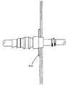
도1은 본 발명에 따른 연결구를 갖는, 맨홀 챔버를 갖는 탱크를 포함하는 주유소 설비의 일부의 부분 절결 측면도이다.1 is a partially cutaway side view of a portion of a gas station installation including a tank having a manhole chamber, having a connector according to the present invention.
도2는 본 발명의 일 실시예에 따른 연결구의 단면도를 도시한다. 2 shows a cross-sectional view of a connector according to an embodiment of the present invention.
도3은 도2에 도시된 연결구의 측면도를 도시한다.Figure 3 shows a side view of the connector shown in Figure 2;
도4는 도2에 도시된 연결구의 제1 관형 슬리브의 단면도를 도시한다.4 shows a cross-sectional view of the first tubular sleeve of the connector shown in FIG.
도5는 도2에 도시된 연결구의 제3 관형 슬리브의 단면도를 도시한다.FIG. 5 shows a cross sectional view of a third tubular sleeve of the connector shown in FIG. 2; FIG.
도6은 도2의 연결구의 단부도를 도시한다.Figure 6 shows an end view of the connector of Figure 2;
도7, 도8 및 도9는 챔버 벽 관통에 사용되는 본 발명에 따른 연결구를 도시한다.7, 8 and 9 show the connector according to the invention for use in chamber wall penetration.
도10은 제1 및 제2 벽이 이중 벽 챔버의 어느 측면 상에 위치되는 상태의, 본 발명의 추가의 실시예에 따른 연결구의 단면도를 도시한다.Figure 10 shows a cross sectional view of a connector according to a further embodiment of the present invention, with the first and second walls positioned on either side of the double wall chamber.
도11은 플랜지의 측면도이다.11 is a side view of the flange.
도12는 본 발명의 추가의 실시예에 따른 연결구의 단면도를 도시한다.Figure 12 illustrates a cross sectional view of a connector according to a further embodiment of the present invention.
도13은 도12의 연결구의 제3 부분의 분해 단면도를 도시한다.FIG. 13 shows an exploded cross-sectional view of a third portion of the connector of FIG. 12.
도14는 플랜지의 측면도를 도시한다.Figure 14 shows a side view of the flange.
도15는 추가의 실시예에 따른 연결구의 단면도를 도시한다.15 shows a cross-sectional view of a connector according to a further embodiment.
도16은 다른 실시예에 따른 연결구의 단면도를 도시한다.16 is a sectional view of a connector according to another embodiment.
도17은 수지로 캡슐화하도록 커버가 플랜지 위를 덮는 상태의, 도15의 실시예를 도시한다.Figure 17 shows the embodiment of Figure 15, with the cover over the flange to encapsulate with resin.
도15, 도16 및 도17에서 제공되는 크기는 단지 예시일 뿐이다. 당업자는 본 명세서에 설명된 실시예들이 다양한 형태 및 크기로 이루어질 수도 있다는 것을 알 수 있을 것이다.The sizes provided in FIGS. 15, 16 and 17 are merely examples. Those skilled in the art will appreciate that the embodiments described herein may be of various shapes and sizes.
본 실시예는 본 발명을 실시하는 출원인에게 알려져 있는 현재의 최상의 방식을 나타낸다. 그러나, 이들만이 달성될 수 있는 방식은 아니다. 이들은 단지 예시로서 도시되고 설명될 것이다. 본 명세서에 사용되는 용어로서, 다음과 같은 정의가 적용된다.This example represents the present best mode known to the applicant practicing the present invention. However, these are not the only ways that can be achieved. These will be shown and described by way of example only. As used herein, the following definitions apply.
챔버 - 유체를 내외에 유지하도록 설계된 임의의 리셉터클. 이는 제한되지는 않지만, 본 명세서에 설명된 바와 같이, 맨홀 및 섬프 챔버를 포함한다. 이는 또한 일반적으로 탱크를 포함한다. chamber -Any receptacle designed to hold the fluid in and out. This includes, but is not limited to, manholes and sump chambers, as described herein. It also generally includes a tank.
에너지 전달 수단 - 임의의 형태의 에너지 공급원을 설명하는 일반 용어. 통상, 이는 전류가 통과할 때, 가열되는 저항 코일의 형태를 취한다. 용어는 또한 초음파 용접 및 유도 용접을 포함하는 다른 용접 기술을 포함한다. Means for delivering energy-a general term describing any form of energy source. Typically, this takes the form of a resistance coil that is heated when an electric current passes through it. The term also includes other welding techniques, including ultrasonic welding and induction welding.
플랜지 - 챔버 벽에 연결구를 부착시키기에 적절한 임의의 칼라(collar). 주어진 예에서, 챔버 벽과 접촉하는 플랜지의 표면은 실질적으로 평탄하다. 그러나, 플랜지가 파이프 입구 개구 둘레에서 챔버의 프로파일에 부합해야만 한다는 것을 이해할 수 있을 것이다. 따라서, 플랜지는 용기 벽의 평면 또는 곡면 또는 코너와의 필요한 접촉을 달성하도록 임의의 적절한 배치를 채용할 수 있다. Flange —any collar suitable for attaching the connector to the chamber wall. In the given example, the surface of the flange in contact with the chamber wall is substantially flat. However, it will be appreciated that the flange must conform to the profile of the chamber around the pipe inlet opening. Thus, the flange can employ any suitable arrangement to achieve the required contact with the plane or curved or corner of the container wall.
유체 - 예는 주로 액체와 연관되어 제공되었지만, 용어 유체는 액체, 증기 및 기체를 지칭한다. 예를 들어, 주유소 설비의 이차 격납형 파이프에서 누설이 일어나면, 휘발유 또는 휘발유 증기가 맨홀 챔버에 수집될 것이다. 휘발유 증기가 챔버의 벽을 통해 주변 토지로 탈출할 수 없는 것은 필수적이다. Fluids -Examples are provided primarily in connection with liquids, but the term fluids refers to liquids, vapors, and gases. For example, if a leak occurs in a secondary containment pipe of a gas station facility, gasoline or gasoline vapors will be collected in the manhole chamber. It is essential that gasoline vapors cannot escape through the walls of the chamber to the surrounding land.
파이프 - 본 명세서에 주어진 예는 대체로 원형 단면의 단일 벽 파이프이다. 그러나, 본 발명은 주름진 박스 단면 등과 "파이프 내 파이프" 형태의 이차 격납형 파이프와 같은 다른 단면도 포함한다. 이 경우에, 파이프에 슬리브를 밀봉하기 위한 밀봉 부재 또는 부트가 오히려 더 복잡할 것이다. 그러나, 이러한 부트는 본 기술 분야에 잘 알려져 있다. 본 발명은 또한 단면이 원형이 아닌 파이프도 포함한다. Pipe -The example given herein is a single wall pipe of generally circular cross section. However, the present invention includes corrugated box cross sections and other cross-sectional views such as secondary containment pipes in the form of " in-pipe " pipes. In this case, the sealing member or boot for sealing the sleeve to the pipe will be rather complicated. However, such a boot is well known in the art. The invention also encompasses pipes that are not circular in cross section.
관형 슬리브 - 이 용어는 매우 넓은 의미를 갖는다. 이는 파이프가 관통할 수도 있는 임의의 관형 구조체를 포함한다. 실질으로로 형태가 원형의 원통으로서 도시되고 설명되었지만, 본 발명에 따른 슬리브가 실질적으로 원형인 단면을 가질 필요는 없으며, 그에 수용될 파이프의 프로파일에 부합될 수도 있다. 슬리브의 원형 단면이 그 전체 길이에 따라 균일할 필요는 없는데, 즉 이는 원통형일 필요는 없다. Tubular Sleeve -This term has a very broad meaning. This includes any tubular structure through which the pipe may pass. Although shown and described in essence as a circular cylinder, the sleeve according to the invention need not have a substantially circular cross section and may conform to the profile of the pipe to be received therein. The circular cross section of the sleeve need not be uniform along its entire length, ie it need not be cylindrical.
유리 강화 플라스틱 ( GPR ) - 용어 GPR은 이러한 관계에 있어서 매우 넓은 의미를 갖는다. 임의의 형태의 섬유가 열경화성 수지 또는 다른 플라스틱 재료를 강화시키는데 사용되는, 임의의 섬유 강화 플라스틱(FRP)을 포함하려는 것이다. Glass Reinforced Plastics ( GPR ) -The term GPR has a very broad meaning in this regard. Any form of fiber is intended to include any fiber reinforced plastic (FRP), which is used to reinforce thermosetting resins or other plastic materials.
도1에 도시된 주유소 설비는 파이프라인(4)을 통해 지하 탱크(3)에 연결되는 한 쌍의 분배 펌프(1, 2)를 포함한다. 파이프라인(4)은 폴리에틸렌 파이프의 인접하게 배열된 섹션으로 형성된다. 파이프라인(4)은 펌프(1, 2)로부터 탱크(3) 바로 위의 맨홀 챔버(6)까지 연장된다. 챔버(6)는 측벽(8) 및 기부(12)를 갖는 GRP 부재에 의해 한정된다.The gas station installation shown in FIG. 1 comprises a pair of dispensing pumps 1, 2 which are connected to an underground tank 3 via a
도1은 파이프라인(4)으로부터 탱크(3)로 연장되는 두 개의 라인을 도시한다. 이들 라인은 연료 공급 시스템의 두 개의 대안적인 형태와 관련되고, 완전함을 위해 양자 모두 도시되어 있다. 실제로, 라인 중 하나만이 파이프라인(4)으로부터 맨홀 챔버(6)로 연장된다. 이들 라인 중 하나는 분배 펌프(1, 2)가 흡입 펌프와 끼워맞춰지는 곳에 사용되는 흡입 라인(14)이다. 도면 부호 16인 다른 라인은 탱크(3)로부터 펌프(1, 2)로 연료를 추진시키도록 작동할 수 있는, 펌프(18)를 통해 파이프라인(4)에 연결되는 압력 라인이다.1 shows two lines extending from the
도1로부터, 파이프라인(4)이 챔버(6)를 통과하는 것을 허용하기 위해서는, 벽(10)에 구멍이 형성되어야만 한다는 것을 알 수 있다. 주변 토지[여기서는 도면 부호 20으로 표시됨]로부터 구멍을 통해 챔버(6)로 물이 누설되는 것을 방지하기 위해서, 파이프는 포함된 도2 내지 도16에 보다 상세하게 도시된 연결구(22)에 의해 원통형 벽(10)에 밀봉된다. 공급 파이프에서 누출 또는 누설되는 경우에, 밀봉체는 또한 연료가 환경으로 탈출하는 것을 방지한다.It can be seen from FIG. 1 that a hole must be formed in the
도2는 더 상세하게 적절한 연결구(22)의 일 예를 도시한다. 이 연결구의 목적은 연결구와 챔버 벽(10) 사이 그리고 연결구와 파이프 구조물 시스템(4) 사이에 강하고, 영구적인 유체 기밀 밀봉체를 형성하는 것이다. 연결구(22)는 GRP 또는 스테인레스강 또는 피복 강, 청동, 황동 또는 황동 합금, 또는 알루미늄과 같은 금속과 같이, GRP에 쉽게 결합할 수 있는 재료로 형성된 제1 관형 슬리브를 포함한다. 중요한 특징은 재료가 알려진 수지, 접착제 등을 사용하여 GRP 벽에 강하고 실질적으로 유체 기밀식인 밀봉체를 형성해야만 한다. 폴리에틸렌 또는 폴리아미드와 같은 플라스틱 재료는 종래의 수지 또는 접착제를 사용하여 GRP에 결합시키는데 좋지 않아서, 두 부품 연결구에 대한 요구가 존재한다.2 shows an example of a
슬리브는(31)는 파이프(도시되지 않음)가 관통할 수 있는 길이방향 축을 갖는 대체로 원통 형상이다. 제2 관형 슬리브(32)는 제1 관형 슬리브의 일 단부 둘레에 몰딩되고, 슬리브(32)는 폴리에틸렌, 폴리아미드 또는 PVDF와 같이 파이프 구조물 시스템과 양립할 수 있는 전기 용융성 중합 플라스틱 재료로 형성된다. 적절한 재료가 이하 더 상세하게 설명될 것이다.The
두 개의 슬립 또는 구성부품 사이에 밀봉체의 유체 기밀 특성을 향상시키기 위해서, 일련의 그루브(groove), 슬롯(slot) 또는 릿지(ridge, 34)가 두 개의 슬리브가 중첩되는 제1 슬리브의 구역에 형성된다. 제2 슬리브가 제1 둘레에 형성될 때, 플라스틱 재료가 이들 그루브를 채워서, 두 개의 구성부품이 사용시 분리되는 것을 방지한다.In order to improve the fluid tightness of the seal between the two slips or components, a series of grooves, slots or
유리하게는, 두 개의 슬리브 사이에 중첩 영역이 존재하도록, 제1 관형 슬리브의 일부가 제2 관형 슬리브의 일부 내에 캡슐화된다. 제2 슬리브 내부에 제1 슬리브의 일부를 캡슐화하는 것은 더 강한 연결구를 생성하고 시간이 경과되면서 덜 누설된다. Advantageously, a portion of the first tubular sleeve is encapsulated in a portion of the second tubular sleeve such that there is an overlap region between the two sleeves. Encapsulating a portion of the first sleeve inside the second sleeve creates a stronger connector and less leaks over time.
연결구가 혹독한 조건, 예컨대, 토양 수축, 침하 또는 다른 운동이 있을 수도 있고, 그리고 연료가 공급 파이프 파손의 경우에 탈출할 수 있는 지하에 종종 사용될 수 있다는 것을 기억해야만 한다.It should be remembered that the connectors may be subjected to harsh conditions, such as soil shrinkage, settlement or other movement, and that fuel may often be used underground where it can escape in case of supply pipe breakage.
선택하기에 따라서는, 두 개의 슬리브 사이의 밀봉체는 O링(36)과 같은 밀봉 수단을 합체함으로써 더 향상될 수 있다. 이 예에서 O링은 슬리브 중 하나 또는 다른 하나의 주연부 둘레의 환형 채널에 포개진다. 제1 슬리브 또는 제2 슬리브 상에 조립 동안, O링 밀봉체가 위치설정될 수 있다는 것을 알 수 있을 것이다. 구성을 용이하게 하기 위해, 이는 통상 연결구 자체의 주 본체 내부에 위치되는 슬리브의 단부를 향해, 제1 관형 슬리브의 외부면 상에 위치설정된다.Depending on the choice, the seal between the two sleeves can be further improved by incorporating a sealing means such as an
O링이 또한 제1 슬리브 단부면(37)에 위치설정되어, 제2 슬리브의 견부(38)에 결합할 수 있다는 것을 알 수 있을 것이다.It will be appreciated that the O-ring can also be positioned at the first sleeve end face 37 to engage the
O링이 연결구에 대해 내부에 있고, 그 내부에서 밀봉되기 때문에, 적어도 연결구의 수명이 매우 긴 수명을 가질 것으로 예상된다.Since the O-rings are internal to the connector and sealed therein, it is expected that at least the life of the connector will have a very long life.
이 예에서, 그리고 O링을 또한 포함하는 후자의 예에서, 적절한 밀봉제의 비드로 대체될 수도 있다. 밀봉제의 사용은 밀봉제가 또한 접착 성질을 가져서, 두 개의 구성부품을 서로 결합시키는데 도움이 될 수도 있다는 점에서 잇점을 가질 수도 있다. 밀봉제의 선택은 그 기술 분야의 재료 전문가에 의해 이루어질 수 있을 것이다.In this example, and in the latter example which also includes an O-ring, it may be replaced with a bead of a suitable sealant. The use of a sealant may have the advantage that the sealant also has adhesive properties, which may help to join the two components together. The choice of sealant may be made by a material expert in the art.
제1 및 제2 슬리브 사이의 밀봉체에 대한 유체 기밀을 강화시키는 역할을 하는 추가의 선택 특징이 있다. 제3 관형 슬리브(33)는 제1 및 제2 슬리브가 중첩되는 구역에서 연결구의 내부면 상에 위치된다. 스테인레스강 등의 금속, 피복 강 또는 중합체로 제조되는, 이 제3 슬리브의 목적은 연료 또는 다른 화학물질에 노출될 때, 수축 또는 연화되는 경우에, 중합 플라스틱 재료 구성부품이 제1 GRP 슬리브로부터 멀리 후퇴되는 것을 방지하는 것이다.There is an additional optional feature that serves to reinforce fluid tightness for the seal between the first and second sleeves. The third
도3은 이 구성 방법으로 얻어진 정돈되고 유선형인 외관 및 형태를 도시하는 연결구(22)의 측면도를 도시한다. 도면 부호 39는 전기 용융 커플링(아래 참조)이 위치설정되고 전기 용융성 플라스틱으로 제조된 연결구의 단부 위에 위치되게 만든다. 이는 또한 불확실한 경우, 연결구의 단부를 식별하는 역할을 한다.Fig. 3 shows a side view of the
도4는 제1 관형 슬리브(31)의 단면도를 도시하고, 슬롯(34)을 더 상세히 도시한다. 도4로부터, 이 GRP 몰딩이 대체로 간단하다는 것을 명확히 알 수 있을 것이다. 슬롯(34)은 폭넓게 다양한 형태, 치수, 위치 및 구조를 취할 수 있다. 필 수적인 특징은 이들이 제2 관형 슬리브 구성부품의 액체 플라스틱 재료가 제조 동안 유동할 수 있는 만입부를 생성한다는 것이다.4 shows a cross-sectional view of the first
다른 형태의 구조에서, 슬롯(34)은 제1 및 제2 슬리브가 별개로 형성되고, 구성 동안 서로 나사 결합되도록, 스크류 나사부의 형태를 취할 수 있다. 이때, 화학 접착제 또는 로킹 스크류(도시되지 않음)가 사용시 낱낱이 흩어지는 것을 방지하는데 사용될 수 있다. In other configurations, the
도5는 제3 관형 슬리브 구성부품의 단면을 도시하고 있다. 이는 제2 관형 슬리브가 제1 관형 슬리브 둘레에 형성된 후에, 밀어 넣어질 수 있지만, 제2 슬리브의 재료는 고온이어서 변형가능하다.5 shows a cross section of a third tubular sleeve component. This can be pushed after the second tubular sleeve is formed around the first tubular sleeve, but the material of the second sleeve is hot and deformable.
사용시, 도8 및 도9를 참조하면, 연결구의 GRP 부분의 단부는 챔버 벽의 구멍을 통해 밀어넣어지고, 일시적으로 제 위치에 유지된다. GRP 붕대(도시되지 않음)가 다음에 하나 또는 양 측면 상의 챔버 벽에 연결구를 밀봉하는데 사용된다. 이러한 배열의 잇점은 강하고 영구적인 실질적으로 유체 기밀식인 밀봉이 쉽게 형성될 수 있도록, 연결구와 챔버 벽 양자 모두 동일한 또는 친화성 재료로 제조된다는 점이다. 필요한 고무 부트(55, 56)는 다음에 이차 파이프 구조물 시스템이 사용되는 챔버 내측에 밀봉체를 형성하도록 종래 방식으로 사용된다. 챔버 외측에, 전기 용융 연결구가 필요시 익스팬더(expander) 및 리듀서(reducer)와 함께 사용되어, 이차 격납부가 존재한다면 이차 격납형 파이프를 수용할 수도 있다.In use, with reference to FIGS. 8 and 9, the end of the GRP portion of the connector is pushed through the hole in the chamber wall and temporarily held in place. GRP bandages (not shown) are then used to seal the connectors to the chamber walls on one or both sides. The advantage of this arrangement is that both the connector and the chamber wall are made of the same or affinity material so that a strong, permanent, substantially fluid tight seal can be easily formed. The
도8에서, 일차 파이프(61) 및 이차 파이프 양자 모두는 이들이 연결구(22)를 관통할 수 있는 크기로 되어 있다. 이차 파이프(60)는 따라서 전기 용융 커플 링(62), 익스팬더(63) 및 전기 용융 커플러(64)에 의해 연결구(22) 외측에 밀봉된다. 일차 및 이차 파이프 사이의 종결은 고무 부트(56)를 사용하여 챔버 내측에서 발생한다.In Fig. 8, both the
도9로부터, 공급 파이프(51)를 포함하는 이차 파이프(50)가 연결구의 내경 보다 크고, 이때 연결구 자체가 이차 격납 시스템의 일부가 된다는 것을 알 수 있을 것이다. 이는 이차 파이프(50)와 연결구(22)의 외측을 효과적으로 연결시키는, 전기 용융 커플링(52), 리듀서(53) 및 커플링(54)의 사용을 통해 달성된다. 이는 본 발명의 제1 태양에 따른 연결구의 융통성의 일부를 보여준다.It can be seen from FIG. 9 that the
플랜지를 합체한 다른 양호한 연결구가 도7에 도시된다. 플랜지(40)는 연결구의 GRP 구성부품으로부터 반경방향으로 연장되고, 제1 관형 슬리브를 구성하는 동안 일체로 형성될 수도 있다. 플랜지는 밀봉될 구멍의 구역의 챔버 벽의 형태에 부합하도록 구성된다. 이 예에서, 평면으로서 도시되지만 다른 구조가 가능하다.Another preferred connector incorporating the flange is shown in FIG. The
사용시, 수지는, 수지가 경화되는 동안 챔버 벽에 대항하여 제 위치에 클램핑되는 플랜지 및 연결구에 인가된다. 플랜지 조립은 상술된 바와 같이 발생한다.In use, the resin is applied to flanges and connectors that are clamped in place against the chamber wall while the resin is cured. The flange assembly takes place as described above.
양호하게는, 전기 용융성 구성부품 또는 구성부품은, 폴리에틸렌; 폴리프로필렌; 폴리비닐 클로라이드; 폴리부틸렌; 폴리우레탄; 폴리아미드 6, 6.6, 6.10, 6.12, 11 및 12를 포함하는 폴리아미드; 폴리에틸렌 테레프탈레이트; 폴리부틸렌 테레프탈레이트, 폴리페닐렌 설파이드; 폴리옥시메틸렌(아세탈); 에틸렌/비닐 알콜 공중합체; 폴리비닐리덴 플루오라이드(PVDF) 및 공중합체; 폴리비닐 플루오라이드(PVF); 테트라플루오로에틸렌-에틸렌 공중합체(ETFE); 테트라플루오로에틸렌-헥 사플루오로에틸렌 공중합체(FEP); 에틸렌 테트라플루오로에틸렌 헥사플로오로프로필렌 삼원공중합체(EFEP); 테트라플로오로에틸렌의 삼원공중합체, 헥사플로오로프로필렌 및 비닐리덴 플루오라이드(THV); 폴리헥사플루오로프로필렌; 폴리테트라플루오로에틸렌(PTFE); 폴리클로로트리플루오로에틸렌; 폴리클로로트리플루오로에틸렌(PCTFE); 플루오리네이티드 폴리에틸렌; 플루오리네이티드 폴리프로필렌; 및 그 혼합물 및 공중합체를 포함하는 그룹으로부터 선택되는 하나 이상의 플라스틱 재료로 형성된다.Preferably, the electrically meltable component or component comprises polyethylene; Polypropylene; Polyvinyl chloride; Polybutylene; Polyurethane;
이 선택은 제한하려는 것이 아니라, 오히려 본 발명의 융통성 및 범주를 보여주려는 것이다. 접합될 파이프에 가장 친화성 있고, 본 유체에 대해 가장 낮은 투과성을 갖는 플라스틱 재료는 재료 전문가에 의해 통상 선택될 것이다. 또한, 두 개 이상의 중합체의 혼합물을 사용하는 것이 알려져 있고, 본 발명은 공지되고 아직 개발될 플라스틱 재료의 혼합물을 포함하도록 연장된다.This choice is not intended to be limiting, but rather to show the flexibility and scope of the present invention. Plastic materials that are most compatible with the pipes to be joined and have the lowest permeability to the fluid will usually be selected by the material expert. It is also known to use mixtures of two or more polymers, and the present invention extends to include mixtures of plastic materials known and still to be developed.
GRP 수지 구성부품은 폴리에스테르 또는 에폭시 수지에 제한되지는 않지만, 이들을 포함하여, 재료 전문가에 의해 선택되는, 임의의 적절한 열경화성 수지로 형성될 수 있다.GRP resin components may be formed of any suitable thermosetting resin, including but not limited to polyester or epoxy resins, selected by material experts.
GRP 슬리브는 핸드 레이업(hand lay-up), 압축 성형 또는 사출 성형을 포함하여 GRP를 몰딩하는데 사용되는 임의의 종래 기술에 의해 형성될 수 있다. 본 발명은 또한 발견될 몰딩 방법까지 확장된다.GRP sleeves may be formed by any conventional technique used to mold GRP, including hand lay-up, compression molding or injection molding. The invention also extends to the molding method to be discovered.
상술된 예는 주로 단일 챔버 벽에 관한 것이다. 그러나, 본 발명에 따른 연결구는, 두 개의 챔버 벽 사이에 간입 공간이 있는 이중 벽 챔버에 동일하게 잘 사 용될 수 있다. 이 경우에, 밀봉체는 연결구와 외부벽 사이 그리고 연결구와 내부벽 사이에 형성된다. 이는 두 개의 붕대를 사용하여 챔버의 하나의 외측 및 하나의 내측에 행해질 수 있고, 또는 플랜지 및 붕대에 의해, 챔버 벽 중 하나 또는 양 측면 상에 행해질 수 있다. 어느 경우든, 챔버 벽 사이의 간입 공간의 완전성은 유지되고 감시된다.The above-mentioned example mainly relates to a single chamber wall. However, the connector according to the invention can equally well be used in a double wall chamber with an intervening space between the two chamber walls. In this case, the seal is formed between the connector and the outer wall and between the connector and the inner wall. This can be done on one outside and one inside of the chamber using two bandages, or on one or both sides of the chamber wall, by flanges and bandages. In either case, the integrity of the enclosed spaces between the chamber walls is maintained and monitored.
요약하면, 본 발명은 전기 용융성 플라스틱 재료로 형성된 파이프와, GRP 챔버 벽 사이에 실질적으로 유체 기밀식인 밀봉체를 형성하기 위한 연결구를 제공한다. 연결구는 파이프와 친화성 있는 전기 용융성 플라스틱 재료로 형성되는 제1 구성부품과, 제1 구성부품에 실질적으로 유체 기밀식인 방식으로 접합되는 제2 구성부품을 포함하고, 제2 구성부품은 GRP 챔버 벽에 결합되도록 된다. 플랜지 또는 제2 구성부품과 연관된 플랜지들은 필요시 채용될 수도 있다. 우수한 밀봉을 행하도록 챔버 벽의 양 측면 상에 플랜지를 사용하는 것이 유리하다. 이는 이중 챔버 벽과의 밀봉체를 형성할 때 특히 중요하다. 플랜지 중 하나만이 연결구의 일체로 된 부분일 수도 있다. 다른 플랜지는 스크류 나사(이하 참조)와 같은 고정 수단에 의해 또는 수지 붕대에 의해 연결구에 연결될 수도 있다.In summary, the present invention provides a connector for forming a substantially fluid tight seal between a pipe formed from an electrically meltable plastic material and a GRP chamber wall. The connector includes a first component formed of an electrically meltable plastic material that is compatible with the pipe, and a second component that is joined to the first component in a substantially fluid tight manner, the second component being a GRP chamber. To be joined to the wall. Flanges associated with the flange or the second component may be employed as needed. It is advantageous to use flanges on both sides of the chamber wall to achieve good sealing. This is particularly important when forming a seal with a double chamber wall. Only one of the flanges may be an integral part of the connector. The other flange may be connected to the connector by fastening means such as screw screws (see below) or by resin bandages.
연결구의 플라스틱 부분은 하나 이상의 세트의 전기 용융 코일과, 파이프에, 일차 또는 이차 또는 양자 모두에 또는 다른 플라스틱 연결구에 대한 전기 용융 용접부를 형성하도록 설계 및 구성된 관련 단자를 합체하고 있다. 간략화를 위해, 그리고, 공구 비용을 저감하기 위해서, 플라스틱 구성부품은 파이프에 연결구를 커플링시키는 역할을 하는, 개별 전기 용융 커플링의 내부면과의 밀착 활주 끼워맞춤 을 형성하도록 될 수도 있다.The plastic portion of the connector incorporates one or more sets of electrical melt coils and associated terminals designed and configured to form an electrical melt weld to the pipe, either primary or secondary or both, or to another plastic connector. For simplicity and to reduce tooling costs, the plastic component may be adapted to form a close sliding fit with the inner surface of the individual electrical melt coupling, which serves to couple the connector to the pipe.
도10 및 도11은 본 발명의 추가의 실시예에 따른 연결구를 도시하고 있다. 이 실시예에서, 연결구(122)는 두 개의 개별 구성부품과, 플라스틱 연결구(131) 및 금속 플랜지형 연결구(133)로 이루어진 제1 부분(124)과, 제2 구성부품 또는 부분(140)을 포함한다. 10 and 11 illustrate a connector according to a further embodiment of the present invention. In this embodiment, the
먼저 부분(124)으로 돌아가면, 연결구(131)의 플라스틱 부분은 하나의 단부인 제1 단부(132)가 일차 파이프(118)의 외측 위로 밀착 활주 끼워맞춤부인 내경을 갖는 대체로 관형 슬리브로 이루어진다. 슬리브의 대향 또는 제2 단부(134)는 이차 파이프(119)의 외측 위로 밀착 활주 끼워맞춤부인 내경을 갖는다. 연결구(131)의 플라스틱 부분은 따라서 일차 파이프가 연결구의 이 부분의 전체 본체를 통과할 수도 있는 길이방향 축을 갖춘 비균일 단면을 갖는, 형상이 대체로 원통형이다. 이차 파이프는 단지 연결구의 일 단부로부터, 그 통로가 연결구의 내경의 감소에 의해 정지되는, 소정 지점까지만 이 길이방향 축을 따라 지나갈 수도 있다.Returning first to the
구성부품(131)의 내부면(144)은 에너지 전달 수단을 수용하고, 이 경우에 전기 가열 와이어의 코일(146)은 플라스틱 구성부품(131)의 내부면에 인접하여 또는 그에 놓인다. 이들 코일은 플라스틱 구성부품(131)으로부터 돌출된 단자 핀(147, 148)에 전기적으로 연결된다. 단자 핀(147, 148)은 플라스틱 구성부품(131)으로부터 돌출되고 그와 일체로 된 중공 원통형 플라스틱 단자 슈라우드(shroud, 149, 150)에 의해 덮여진다. 플라스틱 연결구의 내부면 상에 이러한 유형의 가열 와이어를 놓는 방법이 잘 알려져 있다.The
전기 용융 코일이 연결구 자체에 합체되는 것이 필수적이지는 않다. 간략화를 위해, 그리고 공구 비용 저감을 위해, 연결구의 플라스틱 부분은 파이프에 연결구를 커플링하는 역할을 하는 개별 전기 용융 커플링과의 밀착 활주 끼워맞춤부를 형성하도록 채택될 수도 있다. 고무 부트와 부트들은 필요시 전기 용융 접합부에 연결구의 대향 측면 상에 사용될 수도 있다.It is not necessary for the electric melting coil to be incorporated into the connector itself. For simplicity and to reduce tool costs, the plastic portion of the connector may be adapted to form a tight slide fit with an individual electrical melt coupling that serves to couple the connector to the pipe. Rubber boots and boots may be used on opposite sides of the connector at the electrical melt joint, if desired.
연결구의 제1 부분의 구성을 완료하기 위해서, 플랜지형 금속 연결구(133)r가, 제조 동안, 이차 파이프를 수용하도록 된, 플라스틱 연결구(131)의 단부의 외부 부분 둘레에 실질적으로 유체 유형 방식으로 접합된다. 연결구(133)의 금속 부분은 이차 파이프를 수용하도록 된 연결구의 단부에서 그 외부면 상에 나사결합된 대체로 관형 구역(136)을 포함한다. 그 일면이 챔버 벽의 표면과 부합하고 결합하도록 된 플랜지(137)가 관형 구역(136)으로부터 반경방향 외향으로 연장한다. 따라서, 챔버의 측면이 평탄하면 플랜지가 평탄하거나, 또는 챔버가 만곡 벽을 가지면 플랜지가 만곡될 수도 있다.In order to complete the construction of the first part of the connector, the flanged metal connector 133 r is in a substantially fluid type manner around the outer part of the end of the
상술된 나사 구조체는 연결구의 제1 및 제2 부분을 고정시키고, 챔버 벽의 측면 상에 이들을 견고하게 클램핑하는 고정 수단으로서 작용한다. 볼트 또는 다른 클램핑 수단과 같은 다양한 고정 수단이 사용될 수 있다.The screw structure described above acts as a fixing means for fixing the first and second portions of the connector and for clamping them firmly on the side of the chamber wall. Various fastening means can be used, such as bolts or other clamping means.
이 예에서, 금속 구성부품은 크림핑되거나, 또는 견부(137)와 크림프(138) 사이의 제 위치에 유지되는 플라스틱 구성부품 위에서 내부적으로 스웨이징된다. 적절한 금속은 스테인레스강, 피복 강, 알루미늄, 청동, 황동 또는 황동 합금을 포함한다.In this example, the metal component is crimped or swaged internally over the plastic component held in place between the
이들 두 개의 구성부품 사이의 밀봉체의 유체 기밀 성질을 향상시키기 위해서, 일련의 그루브, 슬롯 또는 릿지(도시되지 않음)가 두 개의 슬리브가 중첩되는 구역에 형성될 수 있다. 접합부가 형성될 때, 플라스틱 재료가 이들 그루브를 채워서, 두 개의 부분이 사용시 분리되는 것을 방지한다. In order to improve the fluid tight properties of the seal between these two components, a series of grooves, slots or ridges (not shown) may be formed in the region where the two sleeves overlap. When the bond is formed, the plastic material fills these grooves to prevent the two parts from separating in use.
선택하기에 따라서는, 두 개의 슬리브 사이의 밀봉체가 밀봉제 비드(도시되지 않음)와 같은 밀봉 수단을 합체함으로써, 더 향상될 수 있다. O링 또는 밀봉제가 슬리브 중 하나 또는 다른 하나의 주연부 둘레의 환형 채널에 포개진다. O링 밀봉체/밀봉제가 제1 또는 제2 슬리브 상에 조립 동안 위치설정될 수도 있다는 것을 알 수 있을 것이다. 구성을 용이하게 하기 위해, 연결구 자체의 본체 내부에 위치되는 슬리브의 단부를 향해 플라스틱 관형 슬리브의 외부면 상에 통상 위치될 수 있을 것이다.Depending on the choice, the seal between the two sleeves can be further improved by incorporating a sealing means such as a sealant bead (not shown). The o-ring or sealant is superimposed on the annular channel around the perimeter of one or the other of the sleeve. It will be appreciated that the o-ring seal / sealant may be positioned during assembly on the first or second sleeve. In order to facilitate the configuration, it may normally be located on the outer surface of the plastic tubular sleeve towards the end of the sleeve which is located inside the body of the connector itself.
밀봉 수단이 또한 제1 슬리브의 단부면(19)에 위치설정되어, 제2 슬리브의 견부(135)와 결합할 수 있다는 것을 알 수 있을 것이다.It will be appreciated that the sealing means can also be positioned at the end face 19 of the first sleeve to engage the shoulder 135 of the second sleeve.
O링이 연결구에 대해 내부에 있고, 그 내부에서 밀봉되기 때문에, 적어도 연결구의 수명은 매우 오랜 수명을 가질 것으로 예상된다.Since the O-ring is internal to the connector and sealed inside it, at least the life of the connector is expected to have a very long life.
연결구(140)의 제2 부분은 내부 나사(143)를 갖는 대체로 관형 구성부품(142)을 포함한다. 이 구성부품의 직경, 치수, 형태, 깊이 및 피치는 이 제2 부분이, 제1 구성부품의 금속 부분의 대응 단부로 그리고 그 위로 나사결합하는 것을 허용하도록 설계된다. 이 제2 부분은 또한 반경방향으로 연장하는 플랜지(145)를 갖는다.The second portion of the
플랜지(145)는 도11에서 더 상세히 볼 수 있다. 플랜지의 면은 일련의 구멍에 의해 천공된다. 구멍 또는 만입부(160)는 플랜지를 돌려 챔버 벽에 대항하여 조이도록 조립시 공구와 플랜지를 결합시키기 위해서 제공된다. 절결부 또는 슬롯은, 플랜지와 벽(이하 참조) 사이의 결합 강도를 증가시키도록, 수지가 플랜지의 본체를 관통하는 것을 허용하기 위해 제공된다.The
다양한 다른 형태 및 장치가 플랜지 상에 회전 힘 수용부(turning purchase)를 제공하는데 사용된다. 하나의 또는 양 부분의 대향 측면은 스패너, 렌치 또는 특별 공구가 사용될 수 있도록 플랫(flat)을 포함할 수 있다. 다르게는, 플랜지는 필요한 힘 수용부를 얻는데 사용될 수 있는 돌출부 또는 절결부를 합체할 수 있다.Various other forms and devices are used to provide a turning purchase on the flange. The opposite side of one or both parts may comprise a flat such that a spanner, wrench or special tool may be used. Alternatively, the flanges can incorporate protrusions or cutouts that can be used to obtain the necessary force reception.
사용시, 연결구의 제1 부분(124)은 플랜지가 챔버 벽에 대항하여 플랫과 결합할 때까지, 통상 챔버 내측으로부터 챔버 벽에 사전 천공된 구멍을 관통한다. 그러나, 이를 행하기 전에, GRP 수지, 유리 섬유 매트 또는 다른 접착제가 플랜지의 면에 또는 구멍 둘레의 챔버 벽에 또는 양자 모두에 인가된다. 유사한 접착제가 챔버 외측 상의 플랜지/챔버 벽에 인가된다. 다르게는, 플랜지(들)는 주위 영역과 실질적으로 플랜지의 노출된 표면 전체 위로 인가된 수지 또는 다른 적절한 접착제와 챔버 벽에 대항하여 견고하게 클램핑된다. 이는 또한 강한 유체 기밀 밀봉을 초래할 것이다.In use, the
추가의 다른 예에서, 수지/접착제는 플랜지의 양 면에, 플랜지와 챔버 벽 사이에 그리고 플랜지의 외부 노출 면 위에 인가될 수도 있다.In still other examples, the resin / adhesive may be applied to both sides of the flange, between the flange and the chamber wall and on the outer exposed side of the flange.
연결구(126)의 제2 부분은 챔버 벽을 통해 연장되는 제1 연결구의 나사부 상 으로 나사 결합되고, 연결구의 두 개의 부분은 일단 접착제가 경화되면, 유체 기밀 밀봉체를 형성하도록 챔버 벽 상으로 조여진다.The second portion of the
일차 및 이차 파이프는 이어서 도10에 도시된 바와 같은 연결구를 관통하고, 연결구에 일차 및 이차 파이프 양자 모두를 밀봉하도록 전류가 코일(146)로 흐른다. The primary and secondary pipes then pass through a connector as shown in FIG. 10, and current flows into the
상기 설명으로부터, 금속 내부 종결 연결구가 제조시 리듀서 연결구에 내부적으로 크림핑된다는 것을 알 수 있을 것이다. 현장에서, 완전한 내부 연결구가 구멍을 관통하고, 외부 플랜지는 연결구를 고정시키는 위치에 나사 결합된다. 금속 플랜지는 이어서 수지 및 유리 섬유 매트를 사용하여 섬프 벽에 결합된다. 그리고 나서, 일차 및 이차 파이프가 전기 용융에 의해 용융될 수 있다.It will be appreciated from the above description that the metal internal termination connector is crimped internally to the reducer connector during manufacture. In the field, a complete inner connector passes through the hole and the outer flange is screwed into position to secure the connector. The metal flange is then bonded to the sump wall using a resin and glass fiber mat. Then, the primary and secondary pipes can be melted by electric melting.
도12, 도13 및 도14는 본 발명의 추가의 실시예를 도시하고 있다. 이 실시예에서, 연결구(222)는 세 개의 부분, 즉 제1 부분(230), 제2 부분(231) 및 제3 부분(232)을 포함한다. 불확실성을 피하기 위해서, 이하 설명되는 다중 구성부품 시스템에서, 품목 231은 청구항 제1항의 "제1 부분"으로 지칭되는 품목에 상당하고, 품목 230 및 232는 "제2" 및 "제3" 품목에 각각 상당한다.12, 13 and 14 show a further embodiment of the present invention. In this embodiment, the
먼저 부분(230)을 돌아보면, 제1 단부(233)는 이차 파이프(234)의 외측 위로 밀착 활주 끼워맞춤부인 내경을 갖는다. 부분(230)은 따라서 이차 파이프가 부분의 전체 본체를 관통할 수도 있는 길이 방향 축을 갖는 비균일 단면을 갖는 형상이 대체로 원통형이다.Turning first to
이 특정 실시예에서, 제1 부분(230) 및 제3 부분(232)은 플라스틱 재료로 형 성되어서, 이들 부분의 내부면은 적어도 일차 및 이차 파이프의 외부면에 전기 용융할 수 있어서, 그 사이에 실질적으로 유체 기밀식인 밀봉체를 형성한다. 부분(230)의 내부면은 에너지 전달 수단, 이 경우에는, 부분(230)의 내부면에 인접하여 또는 그에 놓이는 전기 가열 와이어의 코일(237)을 수용한다. 이들 코일은 플라스틱 부분(230)으로부터 돌출되는 단자 핀(238, 239)에 전기적으로 연결된다. 단자 핀(238, 239)은 부분(230)으로부터 그리고 그와 일체로 된 중공 원통형 플라스틱 단자 슈라우드(240, 241)에 의해 덮여질 수 있다. 플라스틱 연결구의 내부면 상에 이러한 유형의 가열 와이어를 놓는 방법은 잘 알려져 있다.In this particular embodiment, the
연결구의 제1 부분은 제조시 제2 부분(231)에 실질적으로 유체 유형 방식으로 접합된다. 부분(231)은 일반적으로 금속으로 제조되지만, 스크류 나사를 유지하고 상보 스크류 나사형 제품과 결합하기에 충분히 강한 임의의 재료로 제조될 수 있다. 이 예에서, 제2 부분(231)은 금속으로 제조되고, 제1 부분 상으로 외부적으로 스웨이징되거나 크림핑된다. 일단 두 개의 구성부품이 서로 접합되면, 일단 이들 사이의 접합이 이루어지고 더 큰 강도 및 안정성을 제공하면, 외향으로 연장하는 플랜지 또는 후크(242)는, 제1 부분(230)의 측방향 또는 축방향 운동을 방지하도록, 제1 부분(230) 상의 견부 또는 단차부(258)와 결합한다. 제2 부분(231)은 플라스틱 부품(230)의 어떠한 운동도 저지하도록 반경방향 또는 길이방향으로 절결될 수 있다. 이들 두 개의 구성부품 사이의 밀봉체의 유체 기밀 본성을 향상시키기 위해서, 일련의 그루브, 슬롯 또는 릿지(도시되지 않음)가 두 개의 슬리브가 중첩되는 구역에 형성될 수 있다. 접합부가 형성될 때, 플라스틱 재료는 이들 그루 브를 채워서, 두 개의 구성부품이 사용시 분리되는 것을 방지한다.The first portion of the connector is bonded in a substantially fluid type manner to the
선택하기에 따라서는, 두 개의 슬리브 사이의 밀봉체는 O링 또는 밀봉제(도시되지 않음)의 비드와 같은 밀봉 수단을 합체함으로써 더 향상될 수 있다. 이 예에서 O링은 부분 중 하나 또는 다른 하나의 주연부 둘레의 환형 채널에 포개진다. 조립시 제1 부분 또는 제2 부분 상에, O링 밀봉체가 위치설정될 수 있다는 것을 알 수 있을 것이다. 구성을 용이하게 하기 위해, 이는 통상 연결구 자체의 본체 내부에 위치되는 부분의 단부를 향해, 제1 부분의 외부면 상에 위치설정될 것이다.Depending on the choice, the seal between the two sleeves can be further enhanced by incorporating a sealing means such as an o-ring or a bead of sealant (not shown). In this example the O-rings are nested in an annular channel around the perimeter of one or the other of the parts. It will be appreciated that the O-ring seal may be positioned on the first or second portion during assembly. To facilitate configuration, this will usually be positioned on the outer surface of the first portion, towards the end of the portion located inside the body of the connector itself.
밀봉 수단이 또한 제1 부분의 단부면에 위치설정되어, 제2 부분의 견부와 결합할 수 있다는 것을 알 수 있을 것이다.It will be appreciated that the sealing means can also be positioned at the end face of the first part, to engage the shoulder of the second part.
밀봉 수단이 연결구에 대해 내부에 있고, 그 내부에서 밀봉되기 때문에, 적어도 연결구의 수명은 매우 긴 수명을 가질 것으로 예상된다.Since the sealing means are inside and sealed inside the connector, at least the life of the connector is expected to have a very long life.
제2 부분(231)은 공간(244)을 남겨두거나 또는 다른 실시예로서 이차 파이프(234)의 외측 위로의 밀착 활주 끼워맞춤으로서 이차 파이프(234)를 수용할 수 있는 내경을 갖는다. 어느 경우든, 공간이 눈에 보이지 않더라도, 몇몇 형태의 공간이 제2 부분(231)의 내부면과 이차 파이프의 외측 사이에 존재한다.The
제2 부분의 외부면(245)은 스크류 나사 구역(248, 249)에 의해 하나 이상의 반경방향으로 연장하는 플랜지(246, 247)를 수용하도록 되어 있다. 플랜지(들)의 내경은 상보 나사 구역을 포함하도록 되어 있다. 다른 실시예에서, 플랜지(246, 247) 중 하나는 부분(231)의 일체로 된 부분일 수 있다.The outer surface 245 of the second portion is adapted to receive one or more radially extending
플랜지(246, 247)는 챔버 벽의 표면에 부합하고 그와 결합하도록 되어 있다. 따라서, 챔버의 측면이 평탄하다면 플랜지(들)가 평탄하거나, 또는 챔버가 만곡 벽을 가진다면 플랜지(들)이 만곡될 수도 있다.The
이 구성부품의 나사의 직경, 치수, 형태, 깊이 및 피치는 플랜지(들)가 제2 부분의 대응 단부 상으로 그리고 그 위로 나사 결합되는 것을 허용하도록 설계된다. The diameter, dimensions, shape, depth and pitch of the screws of this component are designed to allow the flange (s) to be screwed onto and over the corresponding end of the second part.
플랜지(들)(246, 247)의 통상적인 예는 도14에서 더 상세히 볼 수 있다. 플랜지의 면은 일련의 구멍에 의해 천공되어 있다. 플랜지를 돌려 챔버 벽에 대항하여 조이도록 조립시 플랜지와 공구를 결합하기 위해서 구멍 또는 만입부(270, 272)가 플랜지의 면에 제공된다. 절결부 또는 슬롯(271)이 플랜지와 벽 사이의 결합 강도를 증가시키도록, 사용시 수지가 플랜지의 본체를 관통하는 것을 허용하도록 제공될 수 있다(이하 참조).Typical examples of flange (s) 246, 247 can be seen in more detail in FIG. 14. The face of the flange is perforated by a series of holes. Holes or indents 270 and 272 are provided in the face of the flange to engage the flange and the tool during assembly to turn the flange to tighten against the chamber wall. A cutout or
다양한 다른 형태 및 장치가 플랜지 상의 회전 힘 수용부를 제공하는데 사용될 수 있다. 하나의 또는 양 부분의 대향 측면은 스패너, 렌치 또는 특별 공구가 사용될 수 있도록, 플랫을 포함할 수 있다. 다르게는, 플랜지는 필요한 힘 수용부를 얻는데 사용될 수 있는, 핸들, 돌출부 또는 절결부를 합체할 수 있다.Various other forms and devices can be used to provide rotational force receivers on the flanges. The opposite side of one or both parts may comprise a flat, such that a spanner, wrench or special tool may be used. Alternatively, the flanges can incorporate handles, protrusions or cutouts that can be used to obtain the necessary force reception.
플랜지는 균일한 단면을 갖는 것으로 도시된다. 그러나, 플랜지 상에 스크류 나사 구역을 연장시키기 위해, 플랜지는 중심 구멍 둘레에 연장되고, 연결구를 따라 길이방향으로 연장되는 칼라(도시되지 않음)를 합체할 수 있다. 실질적으로 상기 칼라의 전체 내부면은 다음에 스크류 나사형일 수도 있다.The flange is shown to have a uniform cross section. However, in order to extend the screw thread region on the flange, the flange may incorporate a collar (not shown) that extends around the center hole and extends longitudinally along the connector. Substantially the entire inner surface of the collar may then be screw threaded.
도14를 참조하면, 만입부(272)는 플랜지의 외주연 방향 에지에서의 효과적인 캐스털레이션(castellation)을 하게 되어 있다. 개수, 플랜지의 주변 둘레의 공간, 및 플랜지의 본체 속으로 연장되는 정도를 변동시킬 수 있는, 이들 캐스털레이션은, 두 개의 역할을 한다. 첫째, 이들은 플랜지를 공구가 회전시키고 챔버 벽에 대항하여 조이기 위해 공구가 플랜지와 결합하는 것을 허용한다. 둘째, 수지로 덧씌워진 때, 이들은 연결구와 GRP 챔버 벽 사이의 접합을 상당히 강화시킨다. 따라서, 플랜지의 면을 통해 연장되는 구멍을 갖는 것이 필수적인 것은 아니고 단지 플랜지의 에지에서의 캐스털레이션 또는 만입부이면 된다.Referring to Fig. 14, the
플랜지들 중 양자 모두가 아닌, 하나는 제2 부분(231)의 일체로 된 부분으로서 형성될 수도 있다. 이는 연결구에 증가된 강도를 제공하지만, 연결구가 일방향으로 챔버 벽의 구멍을 관통만 할 수도 있다.One of the flanges, but not both, may be formed as an integral part of the
제2 부분(231)은 또한 제조시 제3 부분(232)에 실질적으로 유체 기밀 방식으로 접합된다. 다시, 이 예에서, 제2 부분은 크림핑되거나 또는 견부(242')와 크림프(243') 사이의 제 위치에 유지되는 제3 부분 위로 형이 외부적으로 스웨이징된다. 제2 및 제3 부분 사이의 접합부는 상술되고 도12 및 도13에 도시된 제1 및 제2 부분 사이의 접합부와 필수적으로 동일하다.The
제3 부분은 이차 파이프(234)와 밀착 활주 끼워맞춤부를 형성하도록 된 제1 구역(250)을 포함한다. 이차 파이프는 단지 일 단부로부터, 부분의 내경의 감소에 의해 정지되는, 소정 지점까지만 제3 부분을 따라 통과할 수도 있다. 부분(232)의 내부면(251)은 에너지 전달 수단, 이 경우에는 제3 부분(232)의 제1 구역(250)의 내부면에 인접하거나 그에 놓여진 전기 가열 와이어의 코일(252)을 수용한다. 이 들 코일은 제2 세트의 코일과 직렬로, 플라스틱 부분(232)으로부터 돌출된 단자 핀(253, 254)에 전기적으로 연결된다(이하 참조).The third portion includes a
제3 부분(232)은 이차 파이프(235)와 밀착 활주 끼워맞춤부를 형성하도록 된 제2 구역(255)을 더 포함한다. 제3 부분(232)의 제2 구역(255)의 내부면(256)은 에너지 전달 수단, 이 경우에는 제3 부분(232)의 제2 구역(255)의 내부면에 인접하거나 또는 그에 놓인 전기 가열 와이어의 코일(257)을 수용한다. 이들 코일은 또한 플라스틱 부분(232)으로부터 돌출된 단자 핀(253, 254)에 전기적으로 연결된다. 따라서, 단자 핀(253, 254)이 활성화될 때, 에너지 전달 수단(252, 257) 양자 모두 활성화되고 일차 파이프(235) 및 이차 파이프(234) 양자 모두에 용융될 것이다.The third portion 232 further includes a
다른 실시예에서, 코일(252, 257)은 단자 핀의 개별 쌍에 연결될 수 있다. 이 배열은 이차 및 일차 파이프에 대한 전기 용융 용접부가 개별 작동으로 형성되는 것을 허용할 것이다.In other embodiments, coils 252 and 257 may be connected to separate pairs of terminal pins. This arrangement will allow the electric melt welds to the secondary and primary pipes to be formed in separate operations.
나사 구역(248, 249)은 제2 구역 상으로 플랜지(246, 247)를 고정시키고, 사용시 챔버 벽의 측면 상에 견고하게 이들을 클램핑하는 고정 수단으로서 작용한다. 볼트 또는 다른 클램핑 수단과 같은 다양한 고정 수단이 사용될 수 있다.The threaded
사용시, 이것이 제 위치에 이미 있다고 가정하면, 제1 플랜지(246)는 이차 파이프 위를 활주한다. 이어서, 제1 부분(230), 제2 부분(231) 및 제3 부분(232)을 포함하는 연결구는 통상적으로 챔버의 내측으로부터 챔버 벽의 사전 천공된 구멍을 통과한다. 플랜지(246)는 다음에 플랜지가 챔버 벽에 대항하여 플랫과 결합할 때까지, 제1 부분 위를 다시 활주하여, 챔버 벽을 통해 연장되는 제2 부분의 나 사 구역(249)으로 나사 결합된다.In use, assuming that it is already in place, the
그러나, 이를 행하기 전에, GRP 수지, 유리 섬유 매트 또는 다른 접착제가 플랜지의 면에 또는 구멍 둘레의 챔버 벽에 또는 양자 모두에 인가된다. 유사한 접착제가 챔버의 외측 상의 플랜지/챔버 벽에 인가된다. 다르게는, 플랜지(들)는 주변 영역과 실질적으로 플랜지의 노출 표면 위에 인가된 수지 다른 적절한 접착제와 챔버 벽에 대항하여 견고하게 클림핑될 수도 있다. 이는 강한 유체 기밀 밀봉체를 초래한다.However, before doing this, a GRP resin, glass fiber mat or other adhesive is applied to the face of the flange or to the chamber wall around the hole or both. Similar adhesive is applied to the flange / chamber walls on the outside of the chamber. Alternatively, the flange (s) may be firmly crimped against the chamber wall with a resin or other suitable adhesive applied to the peripheral area and substantially over the exposed surface of the flange. This results in a strong fluid tight seal.
추가의 다른 예에서, 수지/접착제는 플랜지의 양 면에, 플랜지와 챔버 사이 그리고 플랜지의 외부 노출면 양자 모두에 인가될 수도 있다. In yet another example, the resin / adhesive may be applied to both sides of the flange, between the flange and the chamber, and both on the outer exposed surface of the flange.
제2 플랜지(247)는 다음에 제2 부분의 나사 구역(248)에 나사 결합되고, 두 개의 플랜지는 일단 접착제가 경화되면, 유체 기밀 밀봉체를 형성하도록 챔버 벽 상으로 조여진다.The
다음으로, 일차 및 이차 파이프는 도12에 도시된 바와 같이 연결구를 관통하고, 연결구에 일차 및 이차 파이프 양자 모두를 밀봉하도록 전류가 코일(237, 252, 257)을 흐른다.Next, the primary and secondary pipes pass through the connectors as shown in FIG. 12, and current flows through the
연결구의 이 유형의 플라스틱 부분이 재료 전문가에 의해 선택된 그리고 상술된 바와 같은 폭넓게 다양한 플라스틱 재료로 형성될 수 있다는 것을 알 수 있을 것이다.It will be appreciated that the plastic part of this type of connector can be formed from a wide variety of plastic materials selected by the materials expert and as described above.
본 발명에 따른 연결구는, 강하고 영구적이며, 실질적으로 유체 기밀식인 밀봉체가 쉽게 형성될 수 있도록, 챔버 벽과 동일한 재료 또는 챔버 벽과 친화성 있 는 재료로 제조되는 하나의 부분을 포함한다. 이들은 하나의, 또는 선택하기에 따라서는 두 개의, 전기 용융성 플라스틱 재료로 제조되는 다른 부분을 포함한다. 두 개의 이러한 부분이 제공되면, 파이프가 그 길이방향 축을 따라 연결구를 관통할 수 있도록, 다음에 이들은 제1 부분의 대향 측면 상에 위치된다. 플랜지는 양호하게는 제1 부분으로부터 반경방향 외향으로 연장된다. 제1 부분은 제조시 실질적으로 유체 기밀 방식으로 다른 부분(들)에 접합된다. The connector according to the invention comprises one part made of the same material as the chamber wall or of a material compatible with the chamber wall so that a strong, permanent, substantially fluid tight seal can be easily formed. These include one or, optionally, two other parts made of electrically meltable plastic material. If two such parts are provided, they are then placed on opposite sides of the first part so that the pipe can pass through the connector along its longitudinal axis. The flange preferably extends radially outward from the first portion. The first portion is bonded to the other portion (s) in a substantially fluid tight manner during manufacture.
본 발명에 따른 연결구는 단일 또는 이중 벽 챔버 상에 똑같이 잘 사용될 있다. 밀봉체가 벽의 양 측면 상에 형성되기 때문에, 이중 챔버의 챔버 벽 사이의 간입 구역의 완전성이 유지되고 감시될 수 있다. 이러한 연결구는 도1의 섬프(68, 70)와 같은 섬프의 벽과 파이프 사이에 밀봉체를 형성하는데 똑같이 잘 사용될 수 있다.The connector according to the invention can equally well be used on single or double wall chambers. Since the seal is formed on both sides of the wall, the integrity of the infill area between the chamber walls of the dual chamber can be maintained and monitored. This connector can equally well be used to form a seal between the pipe and the wall of the sump, such as
이차 파이프(234)의 외부면과 이차 부분의 내부면 사이에 형성되는 공간(244)을 감시할 수 있다. 격납 챔버의 벽이 이차로 포함되면, 격납 챔버의 벽의 간입 구역과 공간(244)을 연결시키도록, 구멍(259)이 제2 부분에 천공될 수 있다. 공간(244)과, 벽의 간입 구역을 감시함과 동시에 전체 연결구를 감시할 수 있다.The
이 설명을 위해서, 파이프라는 용어는 일반적으로 원형 단면 파이프를 지칭하기로 한다. 그러나, 본 발명은 또한 박스 단면, 주름형 등과 같은 다른 단면을 갖는 파이프와 또한 단일 벽 또는 이차 격납형 파이프를 포함한다.For the purposes of this description, the term pipe will generally refer to a circular cross-section pipe. However, the present invention also includes pipes having other cross sections, such as box cross sections, corrugated sections, etc., and also single wall or secondary containment pipes.
도15에 도시된 추가의 실시예에서, 일차 파이프(435)와 벽(408)[예컨대, 섬프 또는 챔버의 벽] 사이의 커플링은 다섯 개의 주요 구성부품, 즉 제1 커플링 부(430), 제1 중간 부재(440), 제2 커플링부(450), 제2 중간 부재(460), 및 제3 커플링부(470)를 포함한다. 제1 커플링부(430), 제1 중간 부재(440), 제2 중간 부재(460), 및 제3 커플링부(470)는 그 예가 상기 제공된, 하나 이상의 전기 용융성 플라스틱 재료로 제조된다.In a further embodiment shown in FIG. 15, the coupling between the
불확실성을 피하기 위해서, 이 예에서 설명되는 다중 구성부품 시스템에서, 품목 450은 청구항 제1항에 기재된 "제1 부분"으로 지칭되는 품목에 상당하고, 품목 460 및 440은 "제2" 및 "제3" 부분에 각각 상당한다.In order to avoid uncertainty, in the multi-component system described in this example,
도면에 도시된 바와 같이, 이 예에서, 벽(408)은 사이에 간입 공간(414)을 갖는 이중 벽(410, 412)을 포함한다.As shown in the figure, in this example, the
사이에 간입 공간을 갖는 이차 파이프(434) 내부에 포함된 일차 공급 파이프(435)를 포함하는 이차 격납 파이프 조립체가 도면의 좌측으로부터 벽(408)에 접근한다. 일차 파이프(435)는 벽(408)의 구멍을 관통하고, 도면의 우측을 향해 연장된다. 추가의 파이프 구조물(436)이, 일차 파이프(435)에 연결될 수도 있는 가능한 추가의 파이프 구조물의 일 예로서 도시된다.A secondary containment pipe assembly comprising a
제1 커플링부(430)는 이차 파이프(434)가 제1 커플링부(430)를 지나가도록 구성되고, 이차 파이프(434)가 제1 커플링부(430)의 길이를 따라 대략 중간으로 연장되도록 배열된다. 제1 커플링부(430)는 이차 파이프(434)의 외부면 둘레에 밀착 활주 끼워맞춤부를 형성하도록 된 제1 부분(438)과, 제1 중간 부재(440)에 커플링되도록 된 제2 부분(439)을 포함한다. 릿지, 돌출부 또는 정지부(433)(환형일 수도 있음)는 이차 파이프(434)가 대항하여 맞대도록 제공된다. 이 정지부(433)는 이차 파이프(434)가 제1 커플링부(430) 내부에 삽입될 수 있는 정도를 결정하고, 이차 파이프(434)가 정지부(433)에 대항하여 완전히 삽입될 때, 만족스러운 커플링이 형성되기에 충분하게 떨어져 있는 것을 보장한다. 제1 커플링부(430)는 단자(431, 432)에 전기적으로 연결된, 구역(438, 439)의 에너지 전달 수단[예컨대, 전기 용융 코일(도시되지 않음)]을 더 포함한다.The
제3 커플링부(470)는 일차 파이프(435)의 외부 둘레에 밀착 활주 끼워맞춤부를 제공하도록 된 부분(474)을 포함한다. 제3 커플링부(470)의 내경은 제2 중간 부재(460)에 커플링하도록 된 제2 부분(476)을 제공하도록 넓어진다. 제3 커플링부(470)는 단자(471, 472)에 전기적으로 연결된, 구역(474, 476)의 에너지 전달 수단[예컨대, 전기 용융 코일(도시되지 않음)]을 포함한다.The third coupling portion 470 includes a
제2 커플링부(450)는 벽(408)에 제공되는 구멍 내부에 위치하고, 제2 커플링부(450)와 벽(408) 사이에 유체 기밀 연결체를 형성하도록 구성된다. 현재 양호한 실시예에서, 연료에 내성이 있고, 벽 재료에 결합 또는 접합될 수도 있는 금속 또는 플라스틱 재료가 다르게는 사용될 수도 있지만, 이 커플링부(450)는 황동으로 제조된다. GRP는 다른 적절한 재료이다.The
제2 커플링부(450)는 제1 일체형 부재(451, 452, 453, 454, 458)와, 제2의 초기에 분리된 플랜지 또는 칼라(457)를 포함한다. 플랜지 또는 칼라(457)에는 양호하게는, 제1 부재(451, 452, 453, 454, 458) 상에 제공되는 대응 나사 또는 부착 수단에 부착되게 만들도록, 나사(또는 다른 부착 수단)가 제공되어, 도면에 도시된 구조를 초래한다. 제1 부재[인접 구역(453)] 상의 나사는 설치될 때, 이들이 벽(408)의 일 측면에 있고, 벽의 구멍과 간섭하지 않도록, 위치설정된다.The
밀봉 수단으로서, 선택 O링 또는 밀봉제 비드가 구역(458)의 내부면 상에 그리고 칼라 또는 플랜지(457)의 내부면 상에 제공될 수도 있어서, 밀봉 수단은 벽(410, 412)의 외부면과의 유체 기밀 밀봉체를 형성하거나 또는 향상시킨다.As a sealing means, an optional o-ring or sealant bead may be provided on the inner surface of the zone 458 and on the inner surface of the collar or
또한, 홀 또는 구멍(459)이 구역(451, 452) 사이의 지점으로부터 구역(458)과 칼라(457) 사이의 지점까지 제2 커플링부(450)를 통해 제공될 수도 있어서, 설치시, 벽(408) 내부의 간입 공간(414)은 일차 파이프(435)의 외부와 제2 커플링부(450) 사이의 보이드(416)와 유체 연통한다.Also, a hole or hole 459 may be provided through the
제2 커플링부(450)는 제1 구역(451, 453) 사이에 위치할 수 있고, 제2 중간 부재(460)가 구역(452, 454) 사이에 위치할 수 있도록, 구성된다. 제2 커플링부(450) 제조시, 또는 설치시, 제1 중간 부재(440)는 구역(451, 453) 사이에 삽입되고, 제2 중간 부재(460)는 구역(452, 454) 사이에 삽입되고, 구역(453, 454)은 스웨이징되거나 또는 다르게는 중간 부재(440, 460)를 파지하도록 변형된다.The
설치시, [제1 및 제2 중간 부재(440, 460)가 부착된 상태의] 제2 커플링부(450)는 도면에 도시된 바와 같이 벽의 우측으로부터 좌측 방향으로, 벽(408)의 구멍에 삽입되어, 구역(451)이 벽(408)을 관통한다. [사용되면, O링(456)이 구역(458)의 제 위치에 사전에 놓여진다.] 제2 커플링부(450)는 구역[그리고 O링(456)]이 벽(412)의 외부면에 인접할 때까지 이동된다. 도면에 도시된 구성에서, 벽(410)의 외부면에 대항하여 같은 높이가 될 때까지, [사용된다면, O링(455)이 제 위치에 있는 상태의] 칼라 또는 플랜지(457)는 이어서 구역(453) 위로의 위 치에 나사 결합된다. GRP 본딩, 접착제 또는 다른 밀봉제(490, 491)는 이어서 플랜지(457)와 제2 커플링부(450)의 구역(458) 둘레에, 그리고 일반적으로 제1 및 제2 중간 부재(440, 460) 상으로 벽(410, 412), 구역(457, 458), 및 구역(453, 454)을 중첩하는, 제2 커플링부(450) 둘레에 인가될 수도 있어서, 제2 커플링부(450)와 벽(408) 사이에 유체 기밀 밀봉체를 얻는다. Upon installation, the second coupling portion 450 (with the first and second
제1 커플링부(430)는 이어서 제1 중간 부재(440) 둘레에 위치되어, 제1 커플링부의 부분(439)이 중간 부재(440)와 밀접 끼워맞춰진다.The
일차 파이프(435)는 이어서 제1 커플링부(430)를 통해서, 그리고 순차적으로 제2 커플링부(450)를 통해서 유입된다. 이차 파이프(434)는 정지부(433)까지는 제1 커플링부(430)로 유입된다.The
도면의 우측으로부터, 제3 커플링부(470)는 이어서, 구역(476)이 제2 중간 부재(460) 둘레에 위치하고, 구역(474)이 일차 파이프(435) 둘레에 밀착 활주 끼워맞춤부를 형성하도록, 유입된다.From the right side of the figure, the third coupling portion 470 is then positioned so that the
또한, 제1 커플링부(430) 및 제3 커플링부(470)에 합체된 에너지 전달 수단에는, 단자(431, 432)에 대한 그리고 단자(471, 472)에 대한 전기 공급원의 연결에 의해 전압이 가해진다. 이는 제1 커플링부(430)의 구역(438)과, 이차 파이프(434)의 외부 사이, 제1 커플링부(430)의 구역(439)과 제1 중간 부재(440) 사이, 제3 커플링부(470)의 구역(476)과 제2 중간 부재(460) 사이, 및 제3 커플링부(470)의 구역(474)과 일차 파이프(435)의 외부 사이에 유체 기밀 전기 용융 연결체의 형성을 초래한다.In addition, the energy transfer means incorporated in the
일단, 제1, 제2 및 제3 커플링부(430, 450, 470)와, 제1 및 제2 중간 부재(440, 460)가 설치되면, 제2 커플링부(450) 아래의 보이드(416)는 일차 파이프(435)와 이차 파이프(434) 사이의 간입 공간과 유체 연통한다. 홀 또는 구멍(459)이 보이드(416)와 벽의 간입 공간(414) 사이에 제공되면, 이어서 간입 공간(414)은 결과적으로 일차 파이프(435)와 이차 파이프(434) 사이의 간입 공간과 유체 연통한다.Once the first, second and
도16은 제1 커플링부(530), 제2 커플링부(550) 및 제3 커플링부(570)를 포함하는 연결구의 다른 실시예를 도시하고 있다. 일차 파이프(435), 이차 파이프(434) 및 벽(408)의 배열은 상술된 도15에서와 동일하다.FIG. 16 illustrates another embodiment of a connector including a
제1 커플링부(530), 제2 커플링부(550), 및 제3 커플링부(570)는 그 예가 상기 제공된, 하나 이상의 전기 용융성 플라스틱 재료로 제조된다.The
제1 커플링부(530)는 각각 전기 단자(531, 532)에 연결된 전기 용융 코일(도시 안됨)과 같은 에너지 전달 수단을 합체하고 있는 구역(538, 539)을 포함한다. 구역(538)의 내부면은 이차 파이프(434)의 외부와의 밀착 활주 끼워맞춤부를 형성하도록 구성된다. 도15의 실시예에서와 같이, 돌출부, 릿지 또는 정지부(533)는 이차 파이프(434)가 대항하여 맞대도록 제공된다.The
제3 커플링부(570)는 일차 파이프(435)의 외부와의 밀착 활주 끼워맞춤부를 형성하도록 된 제1 구역(574)과, 제1 커플링부(550)와 커플링하도록 된 이차 구역(576)을 포함한다. 구역(574, 576)은 전기 단자(571, 572)에 연결된, 전기 용융 코일(도시되지 않음)과 같은 에너지 전달 수단을 합체하고 있다.The third coupling portion 570 has a
여기서 제2 커플링부(550)는 전기 용융성 플라스틱 재료로 제조된 일체식 제품(551, 552, 558)을 포함한다. 사실상, 이 일체식 제품은, 도15의 제2 커플링부(450)의 구역(451, 452, 453, 454, 458)과 조합하여, 도15의 실시예의 제1 및 제2 중간 부재(440, 460)와 등가이다. 그러나, 본 실시예에서, 전기 용융성 재료로 형성됨으로써, 제1 및 제3 커플링부(530, 570)는, 개별 중간 부재[상술된 바와 같이(440, 460)] 또는 [상술된 구역(453, 454)의] 스웨이징을 필요로 하지 않고, 전기 용융 본딩을 사용하여 제2 커플링부(550)에 직접 커플링될 수도 있다. The
개별 나사형 플랜지 또는 칼라(557)는 제2 커플링부(550)의 외부면(553) 상에 제공되는 대응 나사와 결합하도록 구성된다. 표면(553) 상의 나사는 설치시, 벽(408)의 한 측면에 있고, 벽의 구멍과 간섭하지 않도록, 위치설정된다. 밀봉제 비드 또는 O링(555, 556)과 같은 임의의 밀봉 수단이 이전과 같이 포함될 수도 있다. 도16을 참조하면, 칼라(557)가 제2 커플링부(550)에 부착되는 기구는 좌측으로부터 우측 방향으로 칼라(557)를 유입하는 것을 포함하여, 칼라는 제2 커플링부(550)의 표면(553) 상에 제공되는 나사와 결합한다. 칼라(557)에 그리고 표면(553) 상에 제공된 나사는 이들 구성부품의 일체로 된 부분으로서 몰딩될 수도 있고, 또는 본 기술분야에 잘 알려져 있는 태핑 기술을 사용하여 후속적으로 형성될 수도 있다. 플랜지 또는 칼라(557)의 두께는, 나사형 플라스틱 구성부품 제조와 연관된 제한으로 인해, 도16에 도시된 두께보다 크게 제조될 수도 있다. Individual threaded flanges or
홀 또는 구멍(559)은 제2 커플링부(550)를 통해 제공될 수도 있어서, 일단 설치되면, 벽(408) 내부의 간입 공간(414)은 제2 커플링부(550)와 일차 파이 프(435)의 외부 사이의 보이드(516)와 유체 연통한다.The hole or
설치시, 제2 커플링부(550)는, 도16에 도시된 바와 같이 벽의 우측으로부터, 좌측 방향으로, 벽(408)의 구멍에 삽입되어, 구역(551)이 벽(408)을 관통한다. [사용된다면, O링 또는 밀봉제 비드(556)는 사전에 구역(558)의 제 위치에 놓일 것이다.] 제2 커플링부(550)는 구역(558)[그리고 O링(556)]이 벽(112)의 외부면에 인접할 때까지 이동된다. [사용된다면, O링이 제 위치에 있는 상태의] 칼라 또는 플랜지(557)는 이어서, 도면에 도시된 바와 같이, 칼라(557)가 벽(410)의 외부면에 대항하여 높이가 같아질 때까지, 구역(553) 위로의 위치에 나사 결합된다. GRP 본딩, 접착제 또는 다른 밀봉제(590, 591)는 이어서 플랜지(557)와 제2 커플링부(550)의 구역(558) 둘레에, 그리고 일반적으로 벽(410, 412)과 중첩하는, 제2 커플링부(550) 둘레에 인가될 수도 있어서, 제2 커플링부(550)와 벽(408) 사이에 유체 기밀 밀봉체를 얻는다.In installation, the
제1 커플링부(530)는 이어서 제 위치로 와서, 제1 커플링부의 구역(539)이 제2 커플링부(550)의 구역(551)과 밀접 끼워맞춰진다.The
일차 파이프(435)는 이어서 제1 커플링부(530)를 통해 그리고 그 결과 제2 커플링부(550)를 통해 유입된다. 이차 파이프(434)는 정지부(533)까지만 제1 커플링부(530)에 유입된다.The
도면의 우측으로부터, 제3 커플링부(570)는 이어서, 구역(576)이 제2 커플링부(550)의 구역(552)에 위치하고, 구역(574)이 일차 파이프(535) 둘레에 밀착 활주 끼워맞춤부를 형성하도록, 유입된다.From the right side of the figure, the third coupling portion 570 then has a zone 576 in the
최종적으로, 제1 커플링부(530) 및 제3 커플링부(570)에 합체된 에너지 전달 수단에는, 단자(531, 532)에 대한 그리고 단자(571, 572)에 대한 전기 공급원의 연결에 의해 전압이 가해진다. 이는 제1 커플링부(530)의 구역(538)과, 이차 파이프(534)의 외부 사이, 제1 커플링부(530)의 구역(539)과 제2 커플링부(550)의 구역(551) 사이, 제3 커플링부(570)의 구역(576)과 제2 커플링부(550)의 구역(552) 사이, 및 제3 커플링부(570)의 구역(574)과 일차 파이프(435)의 외부 사이에 유체 기밀 전기 용융 연결체의 형성을 초래한다.Finally, the energy transfer means incorporated in the
일단, 제1, 제2 및 제3 커플링부(530, 550, 570)가 설치되면, 제2 커플링부(550) 아래의 보이드(516)는 일차 파이프(435)와 이차 파이프(434) 사이의 간입 공간과 유체 연통한다. (도16으로부터 바로 명백히 알 수는 없지만, 채널 또는 리세스가 제2 커플링부(550)의 구역(551)을 통해 제공되어, 보이드(516)는 일차 파이프(435)와 이차 파이프(434) 사이의 간입 공간과 유체 연통한다.) 홀 또는 구멍(559)이 벽의 간입 공간(414)과 보이드(516) 사이에 제공되면, 이러서 간입 공간(414)은 결과적으로 일차 파이프(435)와 이차 파이프(434) 사이의 간입 공간과 유체 연통한다.Once the first, second, and
상술된 몇몇 실시예에서, 하나의 또는 양 플랜지는 스크류 나사 구조를 사용하여 연결구의 본체 상에 보유된다. 이는 플랜지를 제 위치에 보유하는데 사용될 수 있는 고정 수단의 단지 일 형태이다. 예를 들어, 플랜지(들)는 베이어닛식 연결구에 의해 제 위치에 고정될 수 있다. 다르게는, 연결구 본체에 초기에는 기계적으로 고정되지 않는 부유 플랜지 링이 사용될 수 있다. 오히려, 플랜지 링은 챔 버 벽의 섬유 강화 플라스틱 재료에 결합하도록 된 연결구의 부분과의 밀착 활주 끼워맞춤부이고 챔버 벽에 연결구의 부분을 결합시키는데 사용되는 접착제에 의해 제 위치에 유지된다.In some embodiments described above, one or both flanges are held on the body of the connector using a screw thread structure. This is only one form of fastening means that can be used to hold the flange in place. For example, the flange (s) may be secured in place by bayonet connectors. Alternatively, a floating flange ring may be used that is not initially mechanically fixed to the connector body. Rather, the flange ring is a close slide fit with a portion of the connector adapted to bond to the fiber reinforced plastic material of the chamber wall and is held in place by an adhesive used to join the portion of the connector to the chamber wall.
본질적으로, 본 발명은 부착되는 부분에 대해 제 위치에 플랜지(들)를 유지하는데 적절한 임의의 고정 수단, 장치, 또는 구조를 포함하려 한다. 그러나, 스크류 나사 구조는 플랜지(들)가 챔버 벽에 대항하여 더 조여질 수 있는 잇점을 갖는다.In essence, the present invention is intended to include any fastening means, device, or structure suitable for holding the flange (s) in place relative to the portion to which it is attached. However, the screw thread structure has the advantage that the flange (s) can be tightened further against the chamber wall.
챔버 벽에 대한 플랜지의 접착을 향상시키기 위해서, 플랜지의 면은 사용시 접착제로 채워지게 되는, 슬롯, 그루브 또는 채널 등을 포함할 수도 있다. 하나의 적절한 구성은 챔버 벽과 접촉하는 플랜지의 면에 하나 이상의 환형 그루브 또는 채널을 제공하는 것이다. 이들 무단 그루브는 부품이 조립되기 전에, 밀봉제 또는 접착제로 채워질 수 있다. 이 구성은 플랜지와 챔버 벽 사이의 밀봉 및 접착의 품질 및 내구성을 크게 향상시킬 수 있다.In order to improve the adhesion of the flange to the chamber wall, the face of the flange may comprise slots, grooves or channels, etc., which will be filled with adhesive in use. One suitable configuration is to provide one or more annular grooves or channels in the face of the flange that contact the chamber walls. These endless grooves may be filled with sealant or adhesive before the parts are assembled. This configuration can greatly improve the quality and durability of the sealing and adhesion between the flange and the chamber wall.
연결구의 단지 일 측면, 즉 제1 부분이 전기 용융성 플라스틱 재료로 형성될 필요가 있다는 것을 추가로 알 수 있을 것이다. 또한, 고무 부트 또는 부트들을 사용하여 연결구의 제2 부분에 연결이 이루어질 수 있다.It will further be appreciated that only one side of the connector, ie the first part, needs to be formed of an electrically meltable plastic material. A connection can also be made to the second part of the connector using a rubber boot or boots.
도17에 도시된, 추가의 변형예에서, 플랜지 커버(660, 661)는 연결구의 양 측면 상에 플랜지를 놓도록 제공될 수 있다. 플랜지 커버는 양호하게는 섬유 유리 또는 GRP 재료로 형성될 수도 있고, 양호하게는 제조시 수지로 채워진다. 플랜지에 대항하여 그리고 챔버 벽에 대항하여 플랜지 커버를 강제함으로써, 챔버 벽의 일부와 플랜지를 수지 코쿤(cocoon) 내부에 캡슐화하는 적절하게 강한 밀봉체가 제조될 수 있다. 이 구성은 플랜지 커버가 제 위치에 클램핑되는 반면, 수지 또는 접착제가 설정된다는 잇점을 갖는다. 원한다면, 클램핑력이 또한 챔버 벽과 접촉하게 강제하도록, 커버가 사전 결정된 지점에서 플랜지와 접촉할 수 있다. 이들 커버의 추가의 잇점은 이들이 제조 공정시 수지가 연결구의 다른 부분과 접촉할 가능성을 최소화한다는 것이다.In a further variation, shown in FIG. 17, flange covers 660 and 661 may be provided to place the flanges on both sides of the connector. The flange cover may preferably be formed of fiber glass or GRP material and is preferably filled with a resin at the time of manufacture. By forcing the flange cover against the flange and against the chamber wall, a suitably strong seal can be produced that encapsulates the flange and part of the chamber wall inside the resin cocoon. This configuration has the advantage that the flange cover is clamped in place while the resin or adhesive is set. If desired, the cover may contact the flange at a predetermined point so that the clamping force also forces contact with the chamber wall. A further advantage of these covers is that they minimize the likelihood of resin contacting other parts of the connector during the manufacturing process.
부록Appendix
도면 부호Reference
160 설시치 핸드 조임용 핸들160 Handle for mounting the hand
161 수지 침투용 절결부161 Cutout for resin penetration
700 이중 벽 섬프700 double wall sump
701 용접 teat psn tbc701 welding teat psn tbc
702 검사 지점 밸브702 Inspection Point Valve
703 미세 BSP 나사703 fine BSP screws
704 플랜지704 flange
705 커플러705 coupler
706 리듀서706 reducer
707 GRP 수지 필러707 GRP Resin Filler
708 그루브에 부착된 내휘발유 밀봉제Petrol sealant attached to 708 groove
709 나사709 screws
710 나사형 플랜지710 threaded flange
712 섬프와 연결구 사이의 GTP 결합712 GTP bond between sump and end connector
도10과Figure 10 관련된 정보 Related Information
· 금속 내부 종결 연결구는 제조시 리듀서 연결구에 내부적으로 크림핑된다. The metal internal termination connector is crimped internally to the reducer connector during manufacture.
· 현장에서, 완전한 내부 연결구는 구멍을 관통하고, 외부 플랜지는 연결구를 고정시키는 위치에 나사 결합된다. In the field, the complete inner connector passes through the hole and the outer flange is screwed into position to secure the connector.
· 금속 플랜지는 다음에 수지 및 유리 섬유 매트를 사용하여 섬프 벽에 결 합된다. And metal flanges using resin and glass fiber mat in the following are the sum result in the sump wall.
· 일차 및 이차 파이프는 다름에 전기 용융에 의해 용융된다. , Primary and secondary pipe are melted by an electric melting the difference.
Claims (19)
Applications Claiming Priority (10)
| Application Number | Priority Date | Filing Date | Title |
|---|---|---|---|
| GB0327301.8 | 2003-11-25 | ||
| GB0327301A GB0327301D0 (en) | 2003-11-25 | 2003-11-25 | Connection between a pipe and a wall |
| GBGB0400665.6A GB0400665D0 (en) | 2004-01-13 | 2004-01-13 | Improved plastic to metal fitting |
| GB0400665.6 | 2004-01-13 | ||
| GB0401274.6 | 2004-01-21 | ||
| GB0401274A GB0401274D0 (en) | 2004-01-21 | 2004-01-21 | Connection between a pipe and a wall |
| GB0403602A GB0403602D0 (en) | 2004-02-18 | 2004-02-18 | Connection between a pipe and a wall |
| GB0403602.6 | 2004-02-18 | ||
| GB0420132A GB0420132D0 (en) | 2004-09-10 | 2004-09-10 | Connection between a pipe and a wall |
| GB0420132.3 | 2004-09-10 |
Publications (1)
| Publication Number | Publication Date |
|---|---|
| KR20060123189A true KR20060123189A (en) | 2006-12-01 |
Family
ID=33568876
Family Applications (1)
| Application Number | Title | Priority Date | Filing Date |
|---|---|---|---|
| KR1020067010066A KR20060123189A (en) | 2003-11-25 | 2004-11-25 | Connection between a pipe and a wall |
Country Status (14)
| Country | Link |
|---|---|
| US (1) | US7758084B2 (en) |
| EP (2) | EP2119949B1 (en) |
| JP (1) | JP5067785B2 (en) |
| KR (1) | KR20060123189A (en) |
| AT (1) | ATE442544T1 (en) |
| BR (1) | BRPI0416907A (en) |
| CA (1) | CA2589848C (en) |
| DE (1) | DE602004023114D1 (en) |
| ES (2) | ES2332517T3 (en) |
| GB (2) | GB2408782B (en) |
| MX (1) | MXPA06005613A (en) |
| PL (2) | PL2119949T3 (en) |
| PT (2) | PT1690028E (en) |
| WO (1) | WO2005052428A1 (en) |
Cited By (4)
| Publication number | Priority date | Publication date | Assignee | Title |
|---|---|---|---|---|
| KR101123247B1 (en) * | 2009-12-28 | 2012-03-21 | 박인탁 | Covering unit used in connecting pre-insulated pipe and connection method for pre-insulated pipe using it |
| KR101154480B1 (en) * | 2011-06-30 | 2012-06-13 | (주)대진지피아이 | Multi hole pipe connector |
| KR101475938B1 (en) * | 2013-05-14 | 2014-12-23 | (주)복바우 | The connecting structure of corrugated pipe |
| KR20160042403A (en) * | 2016-03-14 | 2016-04-19 | (주)대륜이엔에스 | Cap for protecting standpipe |
Families Citing this family (23)
| Publication number | Priority date | Publication date | Assignee | Title |
|---|---|---|---|---|
| GB2411214B (en) * | 2004-02-17 | 2007-09-12 | Glynwed Pipe Systems Ltd | Sealing of pipe to sump interfaces |
| CA2706144A1 (en) * | 2007-11-28 | 2009-06-04 | Franklin Fueling Systems, Inc. | Entry boot |
| EP2284431B1 (en) * | 2009-08-05 | 2015-03-04 | KE KELIT Kunststoffwerk GmbH | Fitting, especially a connection or attachment piece |
| US20110192468A1 (en) * | 2010-02-09 | 2011-08-11 | Kravis Mark L | Under dispenser containment system with integral penetration fittings and separate fitting support structure |
| US8667687B2 (en) * | 2011-07-27 | 2014-03-11 | Opw Fueling Containment Systems, Inc. | Sump entry fitting |
| CN102954623B (en) * | 2011-08-26 | 2014-12-10 | 上海典峰空调设备工程技术有限公司 | Waterproof sealing sleeve construction process for ground source heat pump buried pipe penetrating large bottom plate of building |
| CA2849791C (en) | 2011-09-28 | 2019-11-26 | Franklin Fueling Systems, Inc. | Split test boot |
| US10113670B2 (en) | 2012-03-30 | 2018-10-30 | Newage Industries, Inc. | Single use wall pass-through system |
| US8870230B2 (en) * | 2012-03-30 | 2014-10-28 | Newage Industries, Inc. | Single use wall pass-through system |
| CN102829276B (en) * | 2012-08-02 | 2014-08-13 | 徐焕松 | Electromagnetic induction heating type steel-plastic composite pipeline full fusion welding structure |
| US9719622B2 (en) | 2013-07-08 | 2017-08-01 | Georg Fischer Harvel Llc | Electrofusion fittings and methods |
| DE102013108881B4 (en) * | 2013-08-16 | 2023-03-16 | Polymont GmbH & Co. KG | socket connection |
| JP6265823B2 (en) * | 2014-04-23 | 2018-01-24 | アロン化成株式会社 | Drainage piping method |
| CN105680294B (en) * | 2014-11-20 | 2018-09-28 | 中国科学院大连化学物理研究所 | A kind of diode pumping vapour of an alkali metal high voltage gain pond |
| WO2016167966A1 (en) * | 2015-04-17 | 2016-10-20 | Saint-Gobain Performance Plastics Corporation | Sterile port connection |
| US20160377213A1 (en) * | 2015-06-26 | 2016-12-29 | Watts Water Technologies, Inc. | Fusion pipe strengthening collar |
| WO2017143019A1 (en) * | 2016-02-16 | 2017-08-24 | Aep International, Inc. | Penetrating fixture and fiberglass sump |
| US10711390B2 (en) * | 2016-03-25 | 2020-07-14 | Dale Christie | Appliance ventilation assembly |
| GB201611752D0 (en) * | 2016-07-06 | 2016-08-17 | Kimplas Piping Systems Ltd | Gas connections |
| CN106949316B (en) * | 2017-03-22 | 2019-06-07 | 华能瑞金发电有限责任公司 | Hole measuring method is protected in one kind open loop on titanium composite panel chimney wall |
| JP7170243B2 (en) * | 2018-11-02 | 2022-11-14 | 内山工業株式会社 | Piping connection structure and connection member |
| IT201900013008A1 (en) * | 2019-07-26 | 2021-01-26 | Nupi Ind Italiane S P A | TOGETHER INCLUDING A DOUBLE-WALLED PE COCKPIT AND AN ELECTRO-WELDABLE BALLET FITTING AND INSTALLATION METHOD OF THE SAME. |
| EP3913270B1 (en) * | 2020-05-19 | 2023-07-26 | ABB Schweiz AG | Hygienic coupling system |
Family Cites Families (21)
| Publication number | Priority date | Publication date | Assignee | Title |
|---|---|---|---|---|
| US985853A (en) * | 1909-06-09 | 1911-03-07 | Mueller Mfg Co H | Bath-tub supply-pipe connection. |
| US2793830A (en) * | 1952-08-25 | 1957-05-28 | Central Scientific Co | Vacuum release valves |
| US2992018A (en) * | 1957-06-03 | 1961-07-11 | Rosan Eng Corp | Self locking threaded coupling |
| US3224796A (en) * | 1962-08-10 | 1965-12-21 | Harold H Burkitt | Wall bushing for pipes and cables |
| US3353849A (en) * | 1965-02-08 | 1967-11-21 | American Flange & Mfg | Plastic container closure assembly |
| US3749424A (en) * | 1972-06-05 | 1973-07-31 | Kdi American Products Inc | Water conduit connector |
| CH669025A5 (en) * | 1985-06-06 | 1989-02-15 | Fischer Ag Georg | METHOD FOR PRODUCING A TENSILE PIPE CONNECTION AND A PIPE CONNECTION. |
| US4828296A (en) * | 1987-02-09 | 1989-05-09 | Swagelok Quick-Connect Co. | Bulkhead mounting for fluid fittings |
| JPH0813523A (en) * | 1994-06-23 | 1996-01-16 | Kowa Kasei Kk | Manhole joint |
| US5704656A (en) * | 1996-06-24 | 1998-01-06 | Rowe; John W. | Adjustable pipe entrance seal |
| US5799988A (en) * | 1996-07-01 | 1998-09-01 | Yeh; Ying Lieh | Oil-tight coupling device |
| GB9726154D0 (en) * | 1997-12-10 | 1998-02-11 | Petrotechnik Ltd | Improvements in and relating to pipe fittings |
| US5967567A (en) * | 1998-01-15 | 1999-10-19 | Advanced Polymer Technology, Inc. | Matingly engaged flexible entry boot |
| JP2001187983A (en) * | 1999-12-28 | 2001-07-10 | Aron Kasei Co Ltd | Protective pipe connecting structure in handhole |
| JP2002048416A (en) * | 2000-08-07 | 2002-02-15 | Yamamoto:Kk | Bathtub piping connection apparatus |
| JP2002328010A (en) * | 2001-04-27 | 2002-11-15 | Okayama City | Jig and method for installing optical fiber for measuring strain |
| WO2003029710A1 (en) * | 2001-10-03 | 2003-04-10 | Petrotechnik Limited | Coupling |
| GB0223054D0 (en) * | 2002-10-04 | 2002-11-13 | Petrotechnik Ltd | Adhesive coupling |
| US6883836B2 (en) * | 2003-01-17 | 2005-04-26 | Stanley Aviation Corporation | Positive locking fitting assembly |
| GB0305008D0 (en) * | 2003-03-05 | 2003-04-09 | Petrotechnik Ltd | Improvements in pipe couplings |
| US7121589B2 (en) * | 2003-09-24 | 2006-10-17 | Norwesco, Inc. | Tank fitting and method of use |
-
2004
- 2004-11-25 KR KR1020067010066A patent/KR20060123189A/en not_active Application Discontinuation
- 2004-11-25 BR BRPI0416907-7A patent/BRPI0416907A/en not_active IP Right Cessation
- 2004-11-25 EP EP09169637.7A patent/EP2119949B1/en not_active Not-in-force
- 2004-11-25 ES ES04798655T patent/ES2332517T3/en active Active
- 2004-11-25 PT PT04798655T patent/PT1690028E/en unknown
- 2004-11-25 AT AT04798655T patent/ATE442544T1/en not_active IP Right Cessation
- 2004-11-25 PL PL09169637T patent/PL2119949T3/en unknown
- 2004-11-25 GB GB0425982A patent/GB2408782B/en not_active Expired - Fee Related
- 2004-11-25 JP JP2006540606A patent/JP5067785B2/en not_active Expired - Fee Related
- 2004-11-25 DE DE602004023114T patent/DE602004023114D1/en active Active
- 2004-11-25 PL PL04798655T patent/PL1690028T3/en unknown
- 2004-11-25 EP EP04798655A patent/EP1690028B1/en not_active Not-in-force
- 2004-11-25 GB GB0612866A patent/GB2427250B8/en not_active Expired - Fee Related
- 2004-11-25 ES ES09169637.7T patent/ES2464720T3/en active Active
- 2004-11-25 CA CA2589848A patent/CA2589848C/en not_active Expired - Fee Related
- 2004-11-25 WO PCT/GB2004/004949 patent/WO2005052428A1/en active Application Filing
- 2004-11-25 PT PT91696377T patent/PT2119949E/en unknown
- 2004-11-25 MX MXPA06005613A patent/MXPA06005613A/en not_active Application Discontinuation
- 2004-12-25 US US10/596,042 patent/US7758084B2/en active Active
Cited By (4)
| Publication number | Priority date | Publication date | Assignee | Title |
|---|---|---|---|---|
| KR101123247B1 (en) * | 2009-12-28 | 2012-03-21 | 박인탁 | Covering unit used in connecting pre-insulated pipe and connection method for pre-insulated pipe using it |
| KR101154480B1 (en) * | 2011-06-30 | 2012-06-13 | (주)대진지피아이 | Multi hole pipe connector |
| KR101475938B1 (en) * | 2013-05-14 | 2014-12-23 | (주)복바우 | The connecting structure of corrugated pipe |
| KR20160042403A (en) * | 2016-03-14 | 2016-04-19 | (주)대륜이엔에스 | Cap for protecting standpipe |
Also Published As
| Publication number | Publication date |
|---|---|
| JP5067785B2 (en) | 2012-11-07 |
| GB2427250B (en) | 2008-08-06 |
| US7758084B2 (en) | 2010-07-20 |
| GB2427250B8 (en) | 2008-09-03 |
| GB0425982D0 (en) | 2004-12-29 |
| US20070057504A1 (en) | 2007-03-15 |
| EP1690028A1 (en) | 2006-08-16 |
| DE602004023114D1 (en) | 2009-10-22 |
| CA2589848A1 (en) | 2006-06-09 |
| GB2408782A (en) | 2005-06-08 |
| PL2119949T3 (en) | 2014-11-28 |
| BRPI0416907A (en) | 2007-01-16 |
| EP2119949B1 (en) | 2014-04-23 |
| GB0612866D0 (en) | 2006-08-09 |
| PT2119949E (en) | 2014-06-02 |
| EP1690028B1 (en) | 2009-09-09 |
| WO2005052428A1 (en) | 2005-06-09 |
| PT1690028E (en) | 2009-11-10 |
| EP2119949A3 (en) | 2010-06-23 |
| JP2007517167A (en) | 2007-06-28 |
| ES2332517T3 (en) | 2010-02-08 |
| GB2408782B (en) | 2008-08-06 |
| PL1690028T3 (en) | 2010-03-31 |
| CA2589848C (en) | 2013-07-09 |
| EP2119949A2 (en) | 2009-11-18 |
| MXPA06005613A (en) | 2006-08-17 |
| ATE442544T1 (en) | 2009-09-15 |
| ES2464720T3 (en) | 2014-06-03 |
| GB2427250A (en) | 2006-12-20 |
Similar Documents
| Publication | Publication Date | Title |
|---|---|---|
| KR20060123189A (en) | Connection between a pipe and a wall | |
| US9366364B2 (en) | Connection between a wall and a pipe | |
| EP2411720B1 (en) | Improved couplings | |
| ZA200603874B (en) | Connection between a pipe and a wall | |
| EP1939508B1 (en) | Coupling | |
| EP1038140B1 (en) | Connection between a wall and a pipe | |
| US20110315697A1 (en) | Improved tank collar | |
| GB2408550A (en) | Compression pipe fitting bonded to fibre reinforced plastic chamber | |
| EP1691968A1 (en) | Sealing element and method | |
| WO2004079245A1 (en) | Pipe-to-wall connections | |
| WO2005068892A1 (en) | Improved plastic to metal pipe fitting | |
| GB2418952A (en) | A containment chamber | |
| US20110155615A1 (en) | Chamber | |
| GB2395242A (en) | Fitting for providing a seal between a pipe and a wall through which it passes |
Legal Events
| Date | Code | Title | Description |
|---|---|---|---|
| A201 | Request for examination | ||
| E902 | Notification of reason for refusal | ||
| E601 | Decision to refuse application | ||
| J201 | Request for trial against refusal decision | ||
| J801 | Dismissal of trial |
Free format text: REJECTION OF TRIAL FOR APPEAL AGAINST DECISION TO DECLINE REFUSAL REQUESTED 20110728 Effective date: 20110927 |