JP5067785B2 - Connection between pipe and wall - Google Patents
Connection between pipe and wall Download PDFInfo
- Publication number
- JP5067785B2 JP5067785B2 JP2006540606A JP2006540606A JP5067785B2 JP 5067785 B2 JP5067785 B2 JP 5067785B2 JP 2006540606 A JP2006540606 A JP 2006540606A JP 2006540606 A JP2006540606 A JP 2006540606A JP 5067785 B2 JP5067785 B2 JP 5067785B2
- Authority
- JP
- Japan
- Prior art keywords
- fitting
- flange
- pipe
- tubular
- chamber wall
- Prior art date
- Legal status (The legal status is an assumption and is not a legal conclusion. Google has not performed a legal analysis and makes no representation as to the accuracy of the status listed.)
- Expired - Fee Related
Links
Images


Classifications
-
- F—MECHANICAL ENGINEERING; LIGHTING; HEATING; WEAPONS; BLASTING
- F16—ENGINEERING ELEMENTS AND UNITS; GENERAL MEASURES FOR PRODUCING AND MAINTAINING EFFECTIVE FUNCTIONING OF MACHINES OR INSTALLATIONS; THERMAL INSULATION IN GENERAL
- F16L—PIPES; JOINTS OR FITTINGS FOR PIPES; SUPPORTS FOR PIPES, CABLES OR PROTECTIVE TUBING; MEANS FOR THERMAL INSULATION IN GENERAL
- F16L5/00—Devices for use where pipes, cables or protective tubing pass through walls or partitions
- F16L5/02—Sealing
-
- F—MECHANICAL ENGINEERING; LIGHTING; HEATING; WEAPONS; BLASTING
- F16—ENGINEERING ELEMENTS AND UNITS; GENERAL MEASURES FOR PRODUCING AND MAINTAINING EFFECTIVE FUNCTIONING OF MACHINES OR INSTALLATIONS; THERMAL INSULATION IN GENERAL
- F16L—PIPES; JOINTS OR FITTINGS FOR PIPES; SUPPORTS FOR PIPES, CABLES OR PROTECTIVE TUBING; MEANS FOR THERMAL INSULATION IN GENERAL
- F16L47/00—Connecting arrangements or other fittings specially adapted to be made of plastics or to be used with pipes made of plastics
- F16L47/20—Connecting arrangements or other fittings specially adapted to be made of plastics or to be used with pipes made of plastics based principally on specific properties of plastics
- F16L47/24—Connecting arrangements or other fittings specially adapted to be made of plastics or to be used with pipes made of plastics based principally on specific properties of plastics for joints between metal and plastics pipes
-
- B—PERFORMING OPERATIONS; TRANSPORTING
- B67—OPENING, CLOSING OR CLEANING BOTTLES, JARS OR SIMILAR CONTAINERS; LIQUID HANDLING
- B67D—DISPENSING, DELIVERING OR TRANSFERRING LIQUIDS, NOT OTHERWISE PROVIDED FOR
- B67D7/00—Apparatus or devices for transferring liquids from bulk storage containers or reservoirs into vehicles or into portable containers, e.g. for retail sale purposes
- B67D7/04—Apparatus or devices for transferring liquids from bulk storage containers or reservoirs into vehicles or into portable containers, e.g. for retail sale purposes for transferring fuels, lubricants or mixed fuels and lubricants
-
- F—MECHANICAL ENGINEERING; LIGHTING; HEATING; WEAPONS; BLASTING
- F16—ENGINEERING ELEMENTS AND UNITS; GENERAL MEASURES FOR PRODUCING AND MAINTAINING EFFECTIVE FUNCTIONING OF MACHINES OR INSTALLATIONS; THERMAL INSULATION IN GENERAL
- F16L—PIPES; JOINTS OR FITTINGS FOR PIPES; SUPPORTS FOR PIPES, CABLES OR PROTECTIVE TUBING; MEANS FOR THERMAL INSULATION IN GENERAL
- F16L47/00—Connecting arrangements or other fittings specially adapted to be made of plastics or to be used with pipes made of plastics
- F16L47/02—Welded joints; Adhesive joints
- F16L47/03—Welded joints with an electrical resistance incorporated in the joint
-
- F—MECHANICAL ENGINEERING; LIGHTING; HEATING; WEAPONS; BLASTING
- F16—ENGINEERING ELEMENTS AND UNITS; GENERAL MEASURES FOR PRODUCING AND MAINTAINING EFFECTIVE FUNCTIONING OF MACHINES OR INSTALLATIONS; THERMAL INSULATION IN GENERAL
- F16L—PIPES; JOINTS OR FITTINGS FOR PIPES; SUPPORTS FOR PIPES, CABLES OR PROTECTIVE TUBING; MEANS FOR THERMAL INSULATION IN GENERAL
- F16L5/00—Devices for use where pipes, cables or protective tubing pass through walls or partitions
- F16L5/02—Sealing
- F16L5/022—Sealing by welding
-
- F—MECHANICAL ENGINEERING; LIGHTING; HEATING; WEAPONS; BLASTING
- F16—ENGINEERING ELEMENTS AND UNITS; GENERAL MEASURES FOR PRODUCING AND MAINTAINING EFFECTIVE FUNCTIONING OF MACHINES OR INSTALLATIONS; THERMAL INSULATION IN GENERAL
- F16L—PIPES; JOINTS OR FITTINGS FOR PIPES; SUPPORTS FOR PIPES, CABLES OR PROTECTIVE TUBING; MEANS FOR THERMAL INSULATION IN GENERAL
- F16L5/00—Devices for use where pipes, cables or protective tubing pass through walls or partitions
- F16L5/02—Sealing
- F16L5/06—Sealing by means of a swivel nut compressing a ring or sleeve
-
- F—MECHANICAL ENGINEERING; LIGHTING; HEATING; WEAPONS; BLASTING
- F16—ENGINEERING ELEMENTS AND UNITS; GENERAL MEASURES FOR PRODUCING AND MAINTAINING EFFECTIVE FUNCTIONING OF MACHINES OR INSTALLATIONS; THERMAL INSULATION IN GENERAL
- F16L—PIPES; JOINTS OR FITTINGS FOR PIPES; SUPPORTS FOR PIPES, CABLES OR PROTECTIVE TUBING; MEANS FOR THERMAL INSULATION IN GENERAL
- F16L5/00—Devices for use where pipes, cables or protective tubing pass through walls or partitions
- F16L5/02—Sealing
- F16L5/14—Sealing for double-walled or multi-channel pipes
-
- B—PERFORMING OPERATIONS; TRANSPORTING
- B29—WORKING OF PLASTICS; WORKING OF SUBSTANCES IN A PLASTIC STATE IN GENERAL
- B29C—SHAPING OR JOINING OF PLASTICS; SHAPING OF MATERIAL IN A PLASTIC STATE, NOT OTHERWISE PROVIDED FOR; AFTER-TREATMENT OF THE SHAPED PRODUCTS, e.g. REPAIRING
- B29C66/00—General aspects of processes or apparatus for joining preformed parts
- B29C66/70—General aspects of processes or apparatus for joining preformed parts characterised by the composition, physical properties or the structure of the material of the parts to be joined; Joining with non-plastics material
- B29C66/72—General aspects of processes or apparatus for joining preformed parts characterised by the composition, physical properties or the structure of the material of the parts to be joined; Joining with non-plastics material characterised by the structure of the material of the parts to be joined
- B29C66/721—Fibre-reinforced materials
-
- B—PERFORMING OPERATIONS; TRANSPORTING
- B29—WORKING OF PLASTICS; WORKING OF SUBSTANCES IN A PLASTIC STATE IN GENERAL
- B29K—INDEXING SCHEME ASSOCIATED WITH SUBCLASSES B29B, B29C OR B29D, RELATING TO MOULDING MATERIALS OR TO MATERIALS FOR MOULDS, REINFORCEMENTS, FILLERS OR PREFORMED PARTS, e.g. INSERTS
- B29K2023/00—Use of polyalkenes or derivatives thereof as moulding material
- B29K2023/04—Polymers of ethylene
- B29K2023/06—PE, i.e. polyethylene
-
- B—PERFORMING OPERATIONS; TRANSPORTING
- B29—WORKING OF PLASTICS; WORKING OF SUBSTANCES IN A PLASTIC STATE IN GENERAL
- B29K—INDEXING SCHEME ASSOCIATED WITH SUBCLASSES B29B, B29C OR B29D, RELATING TO MOULDING MATERIALS OR TO MATERIALS FOR MOULDS, REINFORCEMENTS, FILLERS OR PREFORMED PARTS, e.g. INSERTS
- B29K2023/00—Use of polyalkenes or derivatives thereof as moulding material
- B29K2023/10—Polymers of propylene
- B29K2023/12—PP, i.e. polypropylene
-
- B—PERFORMING OPERATIONS; TRANSPORTING
- B29—WORKING OF PLASTICS; WORKING OF SUBSTANCES IN A PLASTIC STATE IN GENERAL
- B29K—INDEXING SCHEME ASSOCIATED WITH SUBCLASSES B29B, B29C OR B29D, RELATING TO MOULDING MATERIALS OR TO MATERIALS FOR MOULDS, REINFORCEMENTS, FILLERS OR PREFORMED PARTS, e.g. INSERTS
- B29K2027/00—Use of polyvinylhalogenides or derivatives thereof as moulding material
- B29K2027/06—PVC, i.e. polyvinylchloride
-
- B—PERFORMING OPERATIONS; TRANSPORTING
- B29—WORKING OF PLASTICS; WORKING OF SUBSTANCES IN A PLASTIC STATE IN GENERAL
- B29K—INDEXING SCHEME ASSOCIATED WITH SUBCLASSES B29B, B29C OR B29D, RELATING TO MOULDING MATERIALS OR TO MATERIALS FOR MOULDS, REINFORCEMENTS, FILLERS OR PREFORMED PARTS, e.g. INSERTS
- B29K2027/00—Use of polyvinylhalogenides or derivatives thereof as moulding material
- B29K2027/12—Use of polyvinylhalogenides or derivatives thereof as moulding material containing fluorine
- B29K2027/14—PVF, i.e. polyvinyl fluoride
-
- B—PERFORMING OPERATIONS; TRANSPORTING
- B29—WORKING OF PLASTICS; WORKING OF SUBSTANCES IN A PLASTIC STATE IN GENERAL
- B29K—INDEXING SCHEME ASSOCIATED WITH SUBCLASSES B29B, B29C OR B29D, RELATING TO MOULDING MATERIALS OR TO MATERIALS FOR MOULDS, REINFORCEMENTS, FILLERS OR PREFORMED PARTS, e.g. INSERTS
- B29K2027/00—Use of polyvinylhalogenides or derivatives thereof as moulding material
- B29K2027/12—Use of polyvinylhalogenides or derivatives thereof as moulding material containing fluorine
- B29K2027/16—PVDF, i.e. polyvinylidene fluoride
-
- B—PERFORMING OPERATIONS; TRANSPORTING
- B29—WORKING OF PLASTICS; WORKING OF SUBSTANCES IN A PLASTIC STATE IN GENERAL
- B29K—INDEXING SCHEME ASSOCIATED WITH SUBCLASSES B29B, B29C OR B29D, RELATING TO MOULDING MATERIALS OR TO MATERIALS FOR MOULDS, REINFORCEMENTS, FILLERS OR PREFORMED PARTS, e.g. INSERTS
- B29K2027/00—Use of polyvinylhalogenides or derivatives thereof as moulding material
- B29K2027/12—Use of polyvinylhalogenides or derivatives thereof as moulding material containing fluorine
- B29K2027/18—PTFE, i.e. polytetrafluorethene, e.g. ePTFE, i.e. expanded polytetrafluorethene
-
- B—PERFORMING OPERATIONS; TRANSPORTING
- B29—WORKING OF PLASTICS; WORKING OF SUBSTANCES IN A PLASTIC STATE IN GENERAL
- B29K—INDEXING SCHEME ASSOCIATED WITH SUBCLASSES B29B, B29C OR B29D, RELATING TO MOULDING MATERIALS OR TO MATERIALS FOR MOULDS, REINFORCEMENTS, FILLERS OR PREFORMED PARTS, e.g. INSERTS
- B29K2059/00—Use of polyacetals, e.g. POM, i.e. polyoxymethylene or derivatives thereof, as moulding material
-
- B—PERFORMING OPERATIONS; TRANSPORTING
- B29—WORKING OF PLASTICS; WORKING OF SUBSTANCES IN A PLASTIC STATE IN GENERAL
- B29K—INDEXING SCHEME ASSOCIATED WITH SUBCLASSES B29B, B29C OR B29D, RELATING TO MOULDING MATERIALS OR TO MATERIALS FOR MOULDS, REINFORCEMENTS, FILLERS OR PREFORMED PARTS, e.g. INSERTS
- B29K2067/00—Use of polyesters or derivatives thereof, as moulding material
- B29K2067/006—PBT, i.e. polybutylene terephthalate
-
- B—PERFORMING OPERATIONS; TRANSPORTING
- B29—WORKING OF PLASTICS; WORKING OF SUBSTANCES IN A PLASTIC STATE IN GENERAL
- B29K—INDEXING SCHEME ASSOCIATED WITH SUBCLASSES B29B, B29C OR B29D, RELATING TO MOULDING MATERIALS OR TO MATERIALS FOR MOULDS, REINFORCEMENTS, FILLERS OR PREFORMED PARTS, e.g. INSERTS
- B29K2075/00—Use of PU, i.e. polyureas or polyurethanes or derivatives thereof, as moulding material
-
- B—PERFORMING OPERATIONS; TRANSPORTING
- B29—WORKING OF PLASTICS; WORKING OF SUBSTANCES IN A PLASTIC STATE IN GENERAL
- B29K—INDEXING SCHEME ASSOCIATED WITH SUBCLASSES B29B, B29C OR B29D, RELATING TO MOULDING MATERIALS OR TO MATERIALS FOR MOULDS, REINFORCEMENTS, FILLERS OR PREFORMED PARTS, e.g. INSERTS
- B29K2077/00—Use of PA, i.e. polyamides, e.g. polyesteramides or derivatives thereof, as moulding material
-
- B—PERFORMING OPERATIONS; TRANSPORTING
- B29—WORKING OF PLASTICS; WORKING OF SUBSTANCES IN A PLASTIC STATE IN GENERAL
- B29K—INDEXING SCHEME ASSOCIATED WITH SUBCLASSES B29B, B29C OR B29D, RELATING TO MOULDING MATERIALS OR TO MATERIALS FOR MOULDS, REINFORCEMENTS, FILLERS OR PREFORMED PARTS, e.g. INSERTS
- B29K2309/00—Use of inorganic materials not provided for in groups B29K2303/00 - B29K2307/00, as reinforcement
- B29K2309/08—Glass
Landscapes
- Engineering & Computer Science (AREA)
- General Engineering & Computer Science (AREA)
- Mechanical Engineering (AREA)
- Rigid Pipes And Flexible Pipes (AREA)
- Supports For Pipes And Cables (AREA)
- Domestic Plumbing Installations (AREA)
- Joining Of Building Structures In Genera (AREA)
- Quick-Acting Or Multi-Walled Pipe Joints (AREA)
- Infusion, Injection, And Reservoir Apparatuses (AREA)
- Lining Or Joining Of Plastics Or The Like (AREA)
- Branch Pipes, Bends, And The Like (AREA)
- Joints With Sleeves (AREA)
Abstract
Description
本発明は、壁とその壁の開口を貫通するパイプとの間にシールを設けるためのフィッティングと、そのようなシールを設けるための方法と、パイプ、壁、およびその2つの間にシールを設けるフィッティングの組み合わせを含む組立体とに関する。本発明は具体的には、例えば給油場設備の地下の燃料タンクに見られるマンホール・チャンバの壁、または供給ポンプ用の油だめ(サンプ)の壁、特にチャンバまたはサンプの壁がガラス強化プラスチック(GRP)でできているもの、とパイプとの間にシールを提供するのに適用可能である。 The present invention provides a fitting for providing a seal between a wall and a pipe passing through an opening in the wall, a method for providing such a seal, and providing a seal between a pipe, a wall, and the two And an assembly including a combination of fittings. In particular, the present invention relates to the walls of manhole chambers found in, for example, fuel tanks in the basement of gas station facilities, or sump walls for supply pumps, in particular chamber or sump walls made of glass-reinforced plastic ( It is applicable to provide a seal between what is made of GRP) and the pipe.
ガソリンスタンドによく設置されるような地下配管システムは、一般に燃料または化学物質を地下の貯蔵タンクと地上の供給ステーションの間に通じさせるのに用いられる。地下の貯蔵タンクとそれに付随する配管は、その中に含まれる化学物質が地中に漏れる恐れがあったり、実際に過去において漏れたことがあるようなときには、重大な環境被害や火災の危険をもたらす。 Underground piping systems, such as those often installed at gas stations, are commonly used to communicate fuel or chemicals between underground storage tanks and ground supply stations. Underground storage tanks and associated pipes can cause serious environmental damage and fire hazards when there is a risk of chemicals contained in them underground or when they have actually leaked in the past. Bring.
石油会社は、ガソリンスタンド基幹施設を計画し設置する際に、環境問題を優先するようにかなりの圧力を受けている。これには大きな間接コストが伴ってきた。1つの重要な進歩は、石油会社が、対費用効果が高く環境的に容認可能であって、長期にわたると腐食する傾向がある鋼製配管システムの代替品として設置できる、プラスチック材料で作られたパイプライン・システムを使用するようになったことである。 Oil companies are under considerable pressure to prioritize environmental issues when planning and installing gas station infrastructure. This has been accompanied by significant indirect costs. One important advance was made of plastic materials that allows oil companies to install as an alternative to steel piping systems that are cost-effective, environmentally acceptable, and prone to corrosion over time. The use of a pipeline system.
さらに近年、燃料技術が大きく発達した結果、鉛ベースのアンチノック化合物に代わる添加剤を含む代替燃料が市販されるようになった。研究はさらに、燃料からの硫黄含有量および有害物排出の低減にも集中して続けられている。燃料から鉛および硫黄をなくすために、MTBE(メチル第三級ブチルエーテル)などの、複雑な有機または重金属有機添加剤ベースの特殊添加剤およびオクタン価向上剤が開発されてきた。 In recent years, as a result of significant developments in fuel technology, alternative fuels that contain additives to replace lead-based anti-knock compounds have become commercially available. Research continues to focus on reducing sulfur content and toxic emissions from fuels. To eliminate lead and sulfur from fuels, complex organic or heavy metal organic additive-based special additives and octane improvers such as MTBE (methyl tertiary butyl ether) have been developed.
燃料にこういった添加剤が存在すると、重大な環境問題が引き起こされる。かかる問題のいくつかが、「MBTE - How should Europe Respond」というタイトルの記事(非特許文献1)に説明されている。この記事の本文全体を、背景情報として参照によりここに援用する。鉛および他のいくつかの金属が最も効果的なオクタン価向上剤であると、その筆者は結論付けている。しかし、鉛は、環境/健康問題のため段階的撤廃の最終段階にあり、一方、最も入手し易い代替品であるMMT(メチルシクロペンタジエニル・マンガン・トリカルボニル)は、現在あまり受け入れられていない。現在入手可能な他のオクタン価向上剤は、MTBEと、エチル第三級ブチルエーテル(ETBE)および第三級アミル・メチルエーテル(TAME)といった他のエーテル、またはエタノールなどのアルコールに限られる。エーテル類は全て似たような特性および欠点を有する傾向がある。エタノールは、それが容易に入手可能な合衆国の一部の地域と、ブラジルで、すでにガソリン混合成分として使用されている。エタノールは効果的なオクタン価向上剤であるが、「ウォーターフリー」の送液システムを必要とし、地下水問題が伴うという、いくつかの欠点を有する。エタノールは現在、自動車産業では推奨されず、コスト競争力がない。 The presence of these additives in the fuel causes serious environmental problems. Some of these problems are described in an article titled “MBTE-How should Europe Respond” (Non-Patent Document 1). The entire text of this article is incorporated herein by reference as background information. The author concludes that lead and several other metals are the most effective octane improvers. However, lead is in the final stages of phase-out due to environmental / health issues, while MMT (methylcyclopentadienyl manganese manganese tricarbonyl), the most readily available alternative, is currently not well accepted. Absent. Other octane improvers currently available are limited to MTBE and other ethers such as ethyl tertiary butyl ether (ETBE) and tertiary amyl methyl ether (TAME), or alcohols such as ethanol. All ethers tend to have similar properties and disadvantages. Ethanol is already used as a gasoline blending component in some parts of the United States where it is readily available and in Brazil. Ethanol is an effective octane improver, but has several drawbacks that require a “water-free” delivery system and is associated with groundwater problems. Ethanol is currently not recommended in the automotive industry and is not cost competitive.
新しい燃料混合物および特殊な添加剤の導入は、既存のパイプライン・システムが、機械的性能および浸透抵抗に関して当該新しい燃料に対処できるかどうかという問題を石油会社にもたらした。これにより、場合によっては、配管をより高い耐性の材料でできた配管と入れ替えなければならないことになるが、それは必然的に配管を全て不通にすることになる。 The introduction of new fuel mixtures and special additives has led oil companies to the question of whether existing pipeline systems can cope with the new fuels with regard to mechanical performance and penetration resistance. This, in some cases, would require replacing the piping with piping made of a more resistant material, which would inevitably make all the piping out of service.
給油場設備では、供給ポンプと地下燃料貯蔵タンクの間を走る配管は、タンクのマンホール蓋の真上に位置するマンホール・チャンバ内を通過する。チャンバは通常直立した壁によって画成される。この壁には、上から見ると、8角形、正方形、円形あるいは方形の形状のものがあり、各パイプが貫通する孔(アパーチャ)を有する。 In a filling station facility, piping running between the supply pump and the underground fuel storage tank passes through a manhole chamber located directly above the tank manhole cover. The chamber is usually defined by upright walls. When viewed from above, this wall has an octagonal shape, a square shape, a circular shape, or a rectangular shape, and has a hole (aperture) through which each pipe passes.
環境に関する問題を克服するために、現在、この配管は一般的にプラスチック材料から作られており、給油場設備の多くは、二次的包囲構造を採用した設計になっている。これは、各燃料供給パイプラインをそれぞれ二次的包囲パイプラインの中に含み、この二次的包囲パイプラインはその端部で、燃料供給パイプラインに対して封止されるようにできるものである。二次的包囲パイプラインは、燃料供給パイプラインからの漏れが環境に放出されるのを防止し、漏れた石油を遠隔感知装置に導くこともできる。一般に、二次的包囲パイプラインを形成するパイプは、当初は燃料パイプとは別に用意され、燃料パイプが燃料貯蔵タンクと供給ポンプの間に敷設されるときに、その燃料パイプを中に通して覆うようにする。 In order to overcome environmental problems, this pipe is now generally made of plastic material, and many of the filling station facilities are designed with a secondary enclosure structure. This includes each fuel supply pipeline in a secondary enclosing pipeline, which can be sealed at its end to the fuel supply pipeline. is there. The secondary enclosing pipeline prevents leakage from the fuel supply pipeline from being released to the environment and can also direct the leaked oil to a remote sensing device. In general, the pipes forming the secondary enclosing pipeline are initially prepared separately from the fuel pipes, and when the fuel pipe is laid between the fuel storage tank and the supply pump, the fuel pipe is passed through it. Cover.
チャンバを構成する通常の材料は、ガラス強化プラスチック、またはより一般的には、ガラス繊維などの繊維で強化された樹脂等の高分子材料、を成型した繊維強化プラスチック(FRP)である。 A typical material constituting the chamber is a fiber reinforced plastic (FRP) obtained by molding a glass reinforced plastic or, more generally, a polymer material such as a resin reinforced with a fiber such as glass fiber.
マンホール・チャンバ内への水の浸入を避けるために、各アパーチャとパイプの間にそれぞれシールを設けることが望ましい。その目的のために、壁のアパーチャの周りの部分にフィッティングを取り付けるとともに、パイプを覆い、パイプとフィッティングの両方に、例えばジュビリー(jubilee、商標)クリップなどによって固定されるゴム製の「ブーツ」を取り付けることが知られている。そのようなフィッティングの中には、チャンバ壁にボルト止めされるものもあれば、内側部品と外側部品の間に壁を挟み込み、その内側および外側部品が、アパーチャを貫通して延びるねじを切ったコネクタによって互いに保持されるようにしたものもある。こういったコネクタはしばしば、そのコネクタの一部とチャンバ壁との間に配置されるゴム製のシールを有している。
どちらのタイプのフィッティングも、完全に効果的なシールを提供しない。
It is desirable to provide a seal between each aperture and pipe to avoid water ingress into the manhole chamber. To that end, fitting a fitting around the wall aperture and covering the pipe with a rubber “boot” fixed to both the pipe and the fitting, for example by a jubilee ™ clip It is known to install. Some of these fittings are bolted to the chamber wall, while the wall is sandwiched between the inner and outer parts, and the inner and outer parts are threaded to extend through the aperture. Some are held together by connectors. Such connectors often have a rubber seal disposed between a portion of the connector and the chamber wall.
Neither type of fitting provides a completely effective seal.
時間が経つと、どちらのタイプのシールであっても、水がマンホール・チャンバ内に漏れ、チャンバ底部のプールに溜まる恐れがある。これによって、チャンバ底部およびタンク入口の保守が非常に困難になる。さらに、シールに欠陥があると、チャンバ内に漏れ出した石油流体または蒸気が、環境に逃げる惧れがある。 Over time, with either type of seal, water can leak into the manhole chamber and accumulate in the pool at the bottom of the chamber. This makes maintenance of the chamber bottom and tank inlet very difficult. In addition, if the seal is defective, petroleum fluid or steam leaking into the chamber may escape to the environment.
そのようなフィッティングをパイプおよびチャンバ壁の両方に化学的に接着、または電気溶融結合できるならば、それが好ましいはずである。そのようなフィッティングのあるものは、パイプにもチャンバ壁にも電気溶融可能なプラスチック材料から製造され、特許文献1(PetroTechnik Ltd)により知られている。しかしながら、こういったフィッティングは、本発明が問題とするような、チャンバがGRP(これはチャンバやサンプを構成するのに一般に使用される材料である)から建造される場合は使用することができない。
要するに、配管を交換する必要がある場合、あるいは新設の場合、ポリエチレン、ポリプロピレン、ポリアミドなどでできた配管をGRP製のチャンバ壁にシールする必要があるのである。すなわち本発明の目的は、プラスチック材料でできた配管とGRP製のチャンバの間にシールを形成し、上に述べた難点の一部または全てを克服するためのフィッティングを提供することである。 In short, when it is necessary to replace the pipe, or when it is newly installed, it is necessary to seal the pipe made of polyethylene, polypropylene, polyamide or the like to the chamber wall made of GRP. That is, an object of the present invention is to provide a fitting for forming a seal between a pipe made of plastic material and a GRP chamber to overcome some or all of the difficulties mentioned above.
本発明によれば、請求項1によるフィッティングが提供される。一実施形態として、チャンバ壁の開口とパイプ組立体の間に流体密封のシールを設けるためのフィッティングであって、
(i)半径方向に延びる第1のフランジを備える第1の部分と、
(ii)半径方向に延びる第2のフランジを備える第2の部分と、
(iii)前記第1の部分を前記第2の部分に固定するように適合された固定手段とを備え、
前記第1のフランジの第1の表面は、前記開口の周りほぼ全域にわたって前記チャンバ壁と接触するように構成され、該第1のフランジは、繊維強化プラスチックまたは金属から形成され、前記第1の部分はさらに、該第1のフランジから軸方向に延びる第1の管状部と、電気溶融可能なプラスチック材料から形成される管状スリーブとを備え、該管状スリーブは該第1の管状部と流体密封のシールを形成して接合し、前記フィッティングが前記パイプ組立体に結合するように適合され、
前記第2のフランジの第1の表面は、前記開口の周りほぼ全域にわたって前記チャンバ壁と接触するように構成され、該第2のフランジは、繊維強化プラスチックまたは金属から形成されることを特徴とするフィッティングが提供される。
According to the invention, a fitting according to claim 1 is provided. In one embodiment, a fitting for providing a fluid tight seal between an opening in a chamber wall and a pipe assembly comprising:
(I) a first portion comprising a first flange extending in a radial direction;
(Ii) a second portion comprising a second flange extending radially;
(Iii) securing means adapted to secure the first part to the second part;
The first surface of the first flange is configured to contact the chamber wall over substantially the entire periphery of the opening, the first flange formed from fiber reinforced plastic or metal, and the first flange The portion further comprises a first tubular portion extending axially from the first flange and a tubular sleeve formed from an electromeltable plastic material, the tubular sleeve being fluid-tight with the first tubular portion. The fitting is adapted to couple to the pipe assembly;
The first surface of the second flange is configured to contact the chamber wall substantially entirely around the opening, wherein the second flange is formed from fiber reinforced plastic or metal. A fitting is provided.
繊維強化プラスチックから上記フィッティングの第1の部分を形成し、配管に電気溶融可能なプラスチック材料から上記フィッティングの第2の部分を形成することによって、上記フィッティングと上記チャンバ壁の間にも、上記フィッティングと上記パイプの間にも、丈夫で長持ちする流体密封シールを形成することができる。 The fitting is also formed between the fitting and the chamber wall by forming a first portion of the fitting from a fiber reinforced plastic and forming a second portion of the fitting from an electromeltable plastic material in a pipe. A durable and long lasting fluid tight seal can be formed between the pipe and the pipe.
前記第1の部分が、チャンバ壁の開口を通って延びるような形態を有することが好ましい。上記フィッティングの上記第1および第2の部分が、その長さの一部において重なり合い、上記2つの部分の間の上記流体密封シールが、その重なり合う領域に形成されることが好ましい。
The first portion preferably has a configuration that extends through an opening in the chamber wall. Preferably, the first and second portions of the fitting overlap in part of their length, and the fluid tight seal between the two portions is formed in the overlapping region.
好ましい実施形態では、上記第1の部分がさらに、上記第1の部分の本体から半径方向外向きに延びるフランジを備え、上記フランジの第1の表面が、上記開口の周りほぼ全域にわたって上記チャンバ壁と接触するように構成される。 In a preferred embodiment, the first portion further comprises a flange extending radially outward from the body of the first portion, the first surface of the flange extending substantially entirely around the opening of the chamber wall. Configured to contact with.
上記フィッティングがさらに、上記第1および第2の部分の間に配置された封止手段を備え、上記封止手段が、上記重なり合う2つの部分の間に流体密封シールを形成するように適合されるのが好ましい。上記封止手段が、上記2つの部分のどちらかの周りにある外周チャネルに載置されたOリングを備えてもよい。
The fitting further comprises sealing means disposed between the first and second portions, the sealing means being adapted to form a fluid tight seal between the two overlapping portions. Is preferred. The sealing means may comprise an O-ring mounted on an outer peripheral channel around either of the two parts.
上記フィッティングはさらに、金属から形成され、上記第1および第2の部分が重なり合う領域で上記フィッティングの内側に密封嵌合するように適合された、管状スリーブの形をした内側管状部分を備えるのが好ましい。 The fitting further comprises an inner tubular portion in the form of a tubular sleeve formed from metal and adapted to sealingly fit inside the fitting in an area where the first and second portions overlap. preferable.
第2の部分がさらに、前記第2のフランジから軸方向に延びる第2の管状部またはカラーを備えるものが好ましい。 Preferably, the second portion further comprises a second tubular portion or collar that extends axially from the second flange.
前記第1の部分の前記管状スリーブの内壁に加熱巻線が組み込まれたものが好ましい。 It is preferable that a heating winding is incorporated in the inner wall of the tubular sleeve of the first portion.
前記第1のフランジおよび第1の管状部が金属から形成されるものが好ましい。 It is preferable that the first flange and the first tubular portion are made of metal.
前記第1のフランジおよび第1の管状部が、ステンレス鋼、被覆した鉄鋼、アルミニウム、被覆したアルミニウム、または繊維強化プラスチックから形成されるものが好ましい。 Preferably, the first flange and the first tubular portion are formed from stainless steel, coated steel, aluminum, coated aluminum, or fiber reinforced plastic.
前記第1のフランジおよび第1の管状部、並びに前記第2のフランジおよび第2の管状部またはカラーが、同一の材料から形成されるものが好ましい。 It is preferable that the first flange and the first tubular portion, and the second flange and the second tubular portion or collar are formed of the same material.
前記管状スリーブがポリエチレンから形成され、前記第1および第2のフランジがステンレス鋼、または被覆した鉄鋼から形成されるものが好ましい。 It is preferable that the tubular sleeve is made of polyethylene and the first and second flanges are made of stainless steel or coated steel.
前記固定手段が、前記第1および第2の部分上の相補的ねじ山領域を含み、該2つの部分が互いにねじ込まれて、前記第1および第2のフランジが前記チャンバー壁を間に挟みこむように構成されるものが好ましい。 The securing means includes complementary thread regions on the first and second portions, the two portions being screwed together, and the first and second flanges sandwiching the chamber wall therebetween. What is comprised so that it may be desirable is preferable.
前記相補的ねじ山領域が、前記第1の部分の外側および前記第2の部分の内側に設けられるものが好ましい。 It is preferable that the complementary thread region is provided outside the first part and inside the second part.
前記フィッティングがさらに、少なくとも一方の前記フランジを覆い、該少なくとも一方のフランジを接着剤中にカプセル化するような構造を有するカバーを備えるものが好ましい。 Preferably, the fitting further comprises a cover having a structure that covers at least one of the flanges and encapsulates the at least one flange in an adhesive.
更に、前記管状スリーブとその中を通るパイプ組立体とを結合するための電気溶融カップリング部材を有するものが好ましい。 Furthermore, it is preferable to have an electromelting coupling member for coupling the tubular sleeve and the pipe assembly passing therethrough.
前記電気溶融カップリング部材が、エキスパンダまたはレデューサであるものが好ましい。 The electromelting coupling member is preferably an expander or a reducer.
前記フィッティングがさらに、該フィッティング内の空間の密封シールの完全性を監視するためのテストポイントバルブを備えるものが好ましい。 Preferably, the fitting further comprises a test point valve for monitoring the integrity of the hermetic seal of the space within the fitting.
前記パイプ組立体が、二次パイプの中に一次供給パイプが含まれる二次的に囲われたパイプ組立体であるものが好ましい。 Preferably, the pipe assembly is a secondary enclosed pipe assembly in which a primary supply pipe is included in a secondary pipe.
前記パイプ組立体が、一次供給パイプであるものが好ましい。 The pipe assembly is preferably a primary supply pipe.
地下配管システムに組み込まれたものが好ましい。 Those incorporated in the underground piping system are preferred.
給油場設備の配管システムに組み込まれたものが好ましい。 What was integrated in the piping system of the oil filling station equipment is preferable.
好ましい参考例では、上記フィッティングがさらに、上記第1の部分と実質的に流体密封のシールを形成するように適合された第3の部分を備え、上記第3の部分は、電気溶融可能な高分子プラスチック材料から形成される。
In a preferred reference example , the fitting further comprises a third portion adapted to form a substantially fluid tight seal with the first portion, the third portion being a highly meltable high Formed from molecular plastic material.
上記第1および第3の部分は、その長さの一部において重なり合い、上記2つの部分の間の上記流体密封シールが、その重なり合う領域に形成されるのが好ましい。 Preferably, the first and third portions overlap in part of their length, and the fluid tight seal between the two portions is formed in the overlapping region.
上記第1の部分が、1つまたは複数の半径方向に延びるフランジを取り付けられるように適合され、上記フランジが、上記フランジの周りほぼ全域にわたって上記チャンバ壁と係合するように適合されるのが好ましい。 The first portion is adapted to be fitted with one or more radially extending flanges, the flange being adapted to engage the chamber wall substantially entirely around the flange. preferable.
1つのフランジが、上記第1の部分と一体的に形成されるのが好ましい。
さらに、またはその代わりに、1つのフランジが、フランジ固定手段によって上記第1の部分に取り付けられてもよい。
One flange is preferably formed integrally with the first portion.
In addition or alternatively, a flange may be attached to the first part by means of flange fixing.
上記フランジ固定手段が、上記フランジ上および上記第1の部分の外側本体上に、相補的ねじ山を含むのが好ましい。
あるいは、上記フランジ固定手段が、バヨネット固定を含んでもよい。
他の代替方法では、上記フランジが、上記第1の部分を覆って緊密に滑合し、上記フランジ固定手段が接着剤を含む。
Preferably, the flange securing means includes complementary threads on the flange and on the outer body of the first portion.
Alternatively, the flange fixing means may include bayonet fixing.
In another alternative, the flange slides tightly over the first portion and the flange securing means includes an adhesive.
好ましい参考例では、上記第2の部分が、上記第2の部分を電気溶融可能な高分子プラスチック材料から形成されたパイプまたは他のアイテムに電気溶融することができるように、加熱巻線を組み込む。上記第3の部分があるなら、それが、上記第3の部分も電気溶融可能な高分子プラスチック材料から形成されたパイプまたは他のアイテムに電気溶融できるように、加熱巻線を組み込むことができる。特に好ましい参考例では、上記フィッティングはさらに、上記フランジを覆い、上記フランジを接着剤中にカプセル化するように適合されたカバーを備える。
In a preferred reference , the second part incorporates a heating winding so that the second part can be electromelted into a pipe or other item formed from a polymer plastic material that can be electromelted. . If there is a third part, a heating winding can be incorporated so that it can also be electrically melted into a pipe or other item formed from a polymeric plastic material that can also be electrically melted. . In a particularly preferred reference , the fitting further comprises a cover adapted to cover the flange and encapsulate the flange in an adhesive.
他の参考例によれば、チャンバ壁の開口とその開口を貫通するパイプの間に実質的に流体密閉のシールを設けるためのフィッティングであって、(i)上記チャンバ壁の開口を貫通するように適合された第1の管状スリーブと、(ii)上記第1の管状スリーブと流体密封嵌合を形成するように適合された第2の管状スリーブとを備え、上記第1の管状スリーブも、第2の管状スリーブも、上記パイプがそこを貫通できるように適合され、上記第1の管状スリーブが繊維強化プラスチック材料から形成され、上記第2の管状スリーブが電気溶融可能な高分子プラスチック材料から形成されることを特徴とするフィッティングが提供される。
According to another reference example , a fitting for providing a substantially fluid-tight seal between an opening in a chamber wall and a pipe passing through the opening, wherein: (i) the opening extends through the opening in the chamber wall. A second tubular sleeve adapted to form a fluid tight fit with the first tubular sleeve, the first tubular sleeve also comprising: A second tubular sleeve is also adapted to allow the pipe to pass therethrough, the first tubular sleeve is formed from a fiber reinforced plastic material, and the second tubular sleeve is formed from an electromeltable polymeric plastic material. A fitting characterized in that it is formed is provided.
繊維強化プラスチックから上記フィッティングの第1の管状スリーブを形成し、配管に電気溶融可能なプラスチック材料から上記フィッティングの第2の管状スリーブを形成することによって、上記フィッティングと上記チャンバ壁の間にも、上記フィッティングと上記パイプの間にも丈夫で長持ちする流体密封シールを形成することができる。 By forming the first tubular sleeve of the fitting from fiber reinforced plastic and the second tubular sleeve of the fitting from a plastic material that can be electromelted in a pipe, also between the fitting and the chamber wall, A durable and long lasting fluid tight seal can also be formed between the fitting and the pipe.
上記第1および第2の管状スリーブが、その長さの一部において重なり合い、上記2つのスリーブの間の上記流体密封シールが、その重なり合う領域に形成されることが好ましい。 Preferably, the first and second tubular sleeves overlap in part of their length, and the fluid tight seal between the two sleeves is formed in the overlapping region.
上記第1の管状スリーブがさらに、上記スリーブから半径方向外向きに延びるフランジを備え、上記フランジの第1の表面が、上記開口の周りほぼ全域にわたって上記チャンバ壁と接触するように構成されるのが好ましい。 The first tubular sleeve further comprises a flange extending radially outward from the sleeve, the first surface of the flange being configured to contact the chamber wall substantially entirely around the opening. Is preferred.
上記フィッティングがさらに、上記第1の管状スリーブと上記第2の管状スリーブの間に配置された封止手段を備え、上記封止手段が、上記重なり合う2つのスリーブの間に流体密封シールを形成するように適合されるのが好ましい。 The fitting further comprises a sealing means disposed between the first tubular sleeve and the second tubular sleeve, the sealing means forming a fluid tight seal between the two overlapping sleeves. Are preferably adapted as such.
特に好ましい参考例では、上記封止手段が、上記2つのスリーブのどちらかの周りにある外周チャネルに載置されたOリング・シールの形をとる。
In a particularly preferred reference example , the sealing means takes the form of an O-ring seal mounted on an outer peripheral channel around either of the two sleeves.
他の好ましい参考例では、上記フィッティングがさらに、金属から形成され、上記第1および第2の管状スリーブが重なり合う領域で上記フィッティングの内側に密封嵌合するように適合された、第3の管状スリーブを備える。
In another preferred embodiment , a third tubular sleeve wherein the fitting is further formed from metal and adapted to hermetically fit inside the fitting in an area where the first and second tubular sleeves overlap. Is provided.
上記第3の管状スリーブが、ステンレス鋼、被覆した鉄鋼または燃料に耐性のあるポリマーから形成されるのが好ましい。
本発明はまた、かかるフィッティングを含む地下配管システムや、それを組み込むガソリンスタンドの給油場システムにも及ぶことが理解されよう。
The third tubular sleeve is preferably formed from stainless steel, coated steel or a fuel resistant polymer.
It will be appreciated that the present invention also extends to underground piping systems that include such fittings and to gas station service stations that incorporate them.
他の参考例によれば、チャンバ壁の開口とその開口を貫通するパイプの間に実質的に流体密封のシールを設けるためのフィッティングであって、(i)上記パイプの外側と緊密な滑合を形成するように適合された第1の管状スリーブを備える第1の部分と、(ii)その周りほぼ全域にわたって上記チャンバ壁と係合するように適合された、半径方向に延びる第2のフランジを備える第2の部分と、(iii)上記第1の部分を上記第2の部分に固定するように適合された固定手段とを備え、上記第1の部分がさらに、その周りほぼ全域にわたって上記チャンバ壁と係合するように適合された半径方向に延びる第1のフランジと、上記第1のフランジから延びる第2の管状部分とを備えるフィッティングが提供される。
According to another reference example , a fitting for providing a substantially fluid tight seal between an opening in a chamber wall and a pipe passing through the opening, wherein: (i) a tight sliding fit with the outside of the pipe A first portion comprising a first tubular sleeve adapted to form a, and (ii) a radially extending second flange adapted to engage the chamber wall substantially throughout its circumference. And (iii) securing means adapted to secure the first part to the second part, the first part further comprising substantially the entire area around the first part. A fitting is provided that includes a first radially extending flange adapted to engage the chamber wall and a second tubular portion extending from the first flange.
この構成によれば、第1および第2のフランジの間にチャンバ壁を固定することができる。上記フランジと上記チャンバ壁の間に長持ちする防水シールを得るために、GRP樹脂または他の接着剤を片側または両側のフランジの面に使用することができる。
上記第1の管状スリーブが、電気溶融可能なプラスチック材料から形成されるのが好ましい。
According to this configuration, the chamber wall can be fixed between the first and second flanges. To obtain a long lasting waterproof seal between the flange and the chamber wall, GRP resin or other adhesive can be used on one or both flange faces.
The first tubular sleeve is preferably formed from an electromeltable plastic material.
特に好ましい参考例では、上記第1の管状スリーブの内側表面は、加熱巻線を組み込む。したがって、上記フィッティングと上記パイプの間に流体密封シールを形成するために、上記第1の管状スリーブを使用する際に、それを貫通する上記パイプに電気溶融することが可能である。上記パイプは、組み立ての際に一次側または二次側になり得る。
In a particularly preferred reference example , the inner surface of the first tubular sleeve incorporates a heating winding. Thus, when using the first tubular sleeve to form a fluid tight seal between the fitting and the pipe, it is possible to electrofuse the pipe through it. The pipe can be primary or secondary during assembly.
上記第1の管状スリーブおよび上記第1のフランジが異なる材料から形成され、その間に実質的に流体密封の結合を有することが好ましい。このように、上記第1のフランジをGRPに容易に接着する材料から形成することができ、上記第1の管状スリーブを上記パイプに電気溶融可能なプラスチック材料から形成することができる。かかるフランジの材料には、ステンレス鋼、被覆した鉄鋼、アルミニウム、被覆したアルミニウムなどの金属、またはGRP自体またはGRPによく接着するプラスチック材料が含まれる。 Preferably, the first tubular sleeve and the first flange are formed from different materials and have a substantially fluid tight bond therebetween. Thus, the first flange can be formed from a material that easily adheres to GRP, and the first tubular sleeve can be formed from a plastic material that can be electrically melted into the pipe. Such flange materials include metals such as stainless steel, coated steel, aluminum, coated aluminum, or plastic materials that adhere well to GRP itself or GRP.
上記第1のフランジおよび上記第2のフランジが、ほぼ同様の材料から形成されるのが好ましい。
特に好ましい参考例では、上記2つの部分を互いにねじ込み、上記第1と第2のフランジの間に上記チャンバ壁を固定するように、上記固定手段が、上記第1および第2の部分上に相補的ねじ山領域を備える。
Preferably, the first flange and the second flange are formed from substantially similar materials.
In a particularly preferred embodiment , the fixing means are complementary on the first and second parts so that the two parts are screwed together and the chamber wall is fixed between the first and second flanges. A mechanical thread region.
他の好ましい参考例では、上記第1の管状スリーブがポリエチレンから形成され、上記フランジがステンレス鋼、被覆した鉄鋼、または燃料に耐性のあるポリマーから形成される。
In another preferred reference , the first tubular sleeve is formed from polyethylene and the flange is formed from stainless steel, coated steel, or a fuel resistant polymer.
本発明はまた、かかるフィッティングを含む地下配管システムや、それを組み込むガソリンスタンドの給油場システムや、かかるフィッティングの製造方法や、かかるフィッティングを用いて流体密封シールを形成する方法にも及ぶことが理解されよう。 It is understood that the present invention also extends to an underground piping system including such a fitting, a gas station filling station system incorporating the same, a method for manufacturing such a fitting, and a method for forming a fluid tight seal using such a fitting. Let's do it.
他の参考例によれば、チャンバ壁の開口と二次的に囲われたパイプ組立体との間に実質的に流体密封のシールを設け、二次的に囲われたパイプ組立体が二次パイプ内部に含まれる一次的な供給パイプを備え、上記パイプ組立体がチャンバ壁の開口を貫通するフィッティングであって、(i)上記二次パイプと緊密な滑合を形成するように適合され、加熱巻線を組み込む第1の部分と、(ii)その周りほぼ全域にわたって上記チャンバ壁と係合するように適合された、1つまたは複数の半径方向に延びるフランジを取り付けられるように適合された第2の部分と、(iii)第1の領域で上記二次パイプと緊密な滑合を形成するように適合され、第2の領域で一次パイプと緊密な滑合を形成するように適合され、かつ、上記第1および第2の領域が加熱巻線を組み込む第3の部分を備えるフィッティングが提供される。
According to another reference example , a substantially fluid tight seal is provided between the chamber wall opening and the secondary enclosed pipe assembly, wherein the secondary enclosed pipe assembly is secondary. A fitting comprising a primary supply pipe contained within the pipe, wherein the pipe assembly extends through an opening in the chamber wall, and (i) is adapted to form a close slip with the secondary pipe; A first portion incorporating a heating winding; and (ii) adapted to be fitted with one or more radially extending flanges adapted to engage the chamber wall substantially all around it. And (iii) adapted to form a close slip with the secondary pipe in the first region, and (iii) adapted to form a close slip with the primary pipe in the second region. And the first and second Fitting band comprises a third portion incorporating heating windings are provided.
上記参考例に説明した上記フィッティングは、上記一次パイプおよび上記二次パイプに電気溶融結合を形成するように適合された加熱要素を提供するが、上記一次パイプとシールを形成する働きをする上記加熱要素は省略し、従来のゴム製のブーツと置き換えることができることが理解されよう。かかる封止用ブーツは周知であり、一般に上記一次パイプと二次パイプの間の上記隙間空間の完全性を監視するためのバルブを形成する。
The fitting described in the reference example provides a heating element adapted to form an electrofusion bond to the primary pipe and the secondary pipe, but the heating serves to form a seal with the primary pipe. It will be appreciated that the elements can be omitted and replaced with conventional rubber boots. Such sealing boots are well known and generally form a valve for monitoring the integrity of the gap space between the primary and secondary pipes.
上記フランジが、固定手段によって上記第2の部分に固定されるのが好ましい。
上記第2の部分が、2つのフランジを収容するのが好ましい。
ほかの参考例では、フランジの一方が上記第2の部分の一体的部品であってもよく、上記第2のフランジがある場合、それは固定手段によって上記第2の部分に固定される。
Preferably, the flange is fixed to the second part by a fixing means.
The second part preferably accommodates two flanges.
In another reference example , one of the flanges may be an integral part of the second part, where it is fixed to the second part by fixing means.
上記固定手段が、上記第2の部分の外側表面上および上記フランジの内径上の相補的ねじ山領域を含むことがより好ましい。
上記チャンバ壁の両側で固定する2つのフランジが使用されるのが、特に好ましい。
More preferably, the securing means includes complementary thread regions on the outer surface of the second portion and on the inner diameter of the flange.
It is particularly preferred that two flanges are used that are fixed on both sides of the chamber wall.
特に好ましい参考例では、上記チャンバが、二重壁チャンバである。上記チャンバが、上記壁の間の隙間空間を維持するのがより好ましい。上記第1および第3の部分が、電気溶融可能なプラスチック材料から形成されるのが好ましい。
In a particularly preferred reference example , the chamber is a double wall chamber. More preferably, the chamber maintains a gap space between the walls. Preferably, the first and third parts are formed from a plastic material that can be electrically melted.
特に好ましい参考例では、上記加熱巻線が、上記第1および第3の部分の内側表面に組み込まれる。したがって、上記フィッティングと上記二次的に囲われたパイプの間に流体密封シールを形成するために、上記フィッティングを使用する際に貫通する上記パイプ組立体に上記第1および第3の部分を電気溶融することが可能である。
In a particularly preferred reference example , the heating winding is incorporated into the inner surface of the first and third parts. Accordingly, the first and third portions are electrically connected to the pipe assembly that penetrates when the fitting is used to form a fluid tight seal between the fitting and the secondary enclosed pipe. It is possible to melt.
上記第2の部分が、上記第1および第3の部分と異なる材料から形成され、その間に実質的に流体密封の結合を有することが好ましい。このように、上記第2の部分を上記フランジと密封シールを形成する材料から形成することができ、上記第1および第3の部分を上記パイプに電気溶融可能なプラスチック材料から形成することができる。上記フランジは、上記チャンバ壁に容易に接着する材料から形成することができる。かかる適当なフランジ材料には、ステンレス鋼、被覆した鉄鋼、アルミニウム、被覆したアルミニウムなどの金属、GRP、プラスチック材料または燃料に耐性のあるポリマーから形成される。上記フランジと上記チャンバ壁の間に長持ちする防水シールを得るために、樹脂または他の接着剤を片側または両側のフランジ面に使用してもよい。 Preferably, the second portion is formed from a different material than the first and third portions and has a substantially fluid tight bond therebetween. Thus, the second part can be formed from a material that forms a hermetic seal with the flange, and the first and third parts can be formed from a plastic material that can be electrically melted into the pipe. . The flange may be formed from a material that readily adheres to the chamber wall. Such suitable flange materials are formed from stainless steel, coated steel, aluminum, metals such as coated aluminum, GRP, plastic materials or fuel resistant polymers. In order to obtain a long lasting waterproof seal between the flange and the chamber wall, resin or other adhesive may be used on one or both flange surfaces.
複数のフランジがある場合は、それらがほぼ同様の材料から形成されるのが好ましい。
好ましい参考例では、上記シールの完全性を、上記第2の部分の内側表面と上記二次パイプの外側表面の間に形成された空間を監視することによって検査することができる。
Where there are multiple flanges, they are preferably formed from substantially similar materials.
In a preferred reference example , the integrity of the seal can be checked by monitoring the space formed between the inner surface of the second part and the outer surface of the secondary pipe.
特に好ましい参考例では、上記シールの完全性を、二次的に囲われた壁の間隙を介して監視することができ、上記第2の部分の本体を通るアパーチャがこの目的のために設けられる。
In a particularly preferred reference , the integrity of the seal can be monitored via a secondary enclosed wall gap, and an aperture through the body of the second part is provided for this purpose. .
上記シールの完全性が、上記第2の部分の内側表面と上記二次パイプの外側表面の間に形成された空間と上記間隙を、通路を介して連結することによって監視されるのがより好ましい。
ほかの参考例では、上記第2の部分の内側表面と上記二次パイプの外側表面の間に形成された上記空間が、テスト・ポイント・バルブを介して監視される。
More preferably, the integrity of the seal is monitored by connecting the space formed between the inner surface of the second part and the outer surface of the secondary pipe and the gap through a passage. .
In another reference example , the space formed between the inner surface of the second part and the outer surface of the secondary pipe is monitored via a test point valve.
次に、本発明を、例を用いて添付の図面を参照しながら説明する。図15、16および17に与えられた寸法は、例として取り上げたに過ぎない。本明細書に記載の実施形態及び参考例を様々な形状およびサイズで行うことができることが当業者には理解されよう。
The present invention will now be described by way of example with reference to the accompanying drawings. The dimensions given in FIGS. 15, 16 and 17 are merely taken as examples. Those skilled in the art will appreciate that the embodiments and reference examples described herein can be made in a variety of shapes and sizes.
本実施形態は、本発明を実施している出願人が知る現在最良の方法を示す。しかし、それらだけが本発明を実現できる方法ではない。本実施形態は例としてのみ示され、説明される。本明細書で使用される用語として、以下の定義が適用される。 This embodiment represents the best method presently known to applicants implementing the present invention. However, they are not the only methods that can implement the present invention. This embodiment is shown and described only as an example. As terms used herein, the following definitions apply:
チャンバ − 流体を中に入れておく、あるいは中に入れないように設計された任意の容器である。これは、本明細書で説明するマンホール・チャンバおよび油だめ(サンプ)チャンバであるが、それに限定されない。これは一般的にタンクも含む。 Chamber—Any container designed to contain or not contain fluid. This is the manhole chamber and sump chamber described herein, but is not limited thereto. This generally also includes a tank.
エネルギー伝達手段 − 任意の形のエネルギー源を記述する一般的な用語である。一般に、電流を通したときに熱くなる抵抗巻線の形をとる。この用語にはまた、超音波溶接および誘導溶接を含む他の溶接技術も含まれる。 Energy transfer means-a general term describing any form of energy source. In general, it takes the form of a resistive winding that heats up when a current is passed through it. The term also includes other welding techniques including ultrasonic welding and induction welding.
フランジ − フィッティングをチャンバ壁に取り付けるのに適した任意のカラー(環)である。所与の例では、チャンバ壁に接触するフランジの表面はほぼ平面状である。ただし、フランジは、パイプ入口開口の周りのチャンバ壁の形状とあっていなければならないことを理解されたい。したがって、フランジは、容器壁の平坦または湾曲した表面、さらにはコーナとの必要な接触を実現するように合わせた、任意の適当な形状を採用することができる。 Flange—Any collar suitable for attaching the fitting to the chamber wall. In the given example, the surface of the flange that contacts the chamber wall is substantially planar. However, it should be understood that the flange must match the shape of the chamber wall around the pipe inlet opening. Thus, the flange can adopt any suitable shape tailored to achieve the required contact with the flat or curved surface of the container wall as well as the corners.
流体 − 所与の例は、主に液体に関するが、流体という用語は、液体、蒸気および気体を示す。例えば、給油場設備内の二次的に囲われたパイプに漏れが生じた場合、石油または石油の蒸気がマンホール・チャンバ内に集まる。この石油の蒸気が、チャンバの壁を通って周囲の地面に漏れ出ることができないことは必須である。 Fluid-The given example relates primarily to liquids, but the term fluid refers to liquids, vapors and gases. For example, if a leak occurs in a secondary enclosed pipe in a filling station facility, oil or petroleum vapor collects in the manhole chamber. It is essential that this oil vapor cannot escape through the chamber walls to the surrounding ground.
パイプ − 本明細書に示される例は、ほぼ円形の断面をした単一壁パイプである。ただし、本発明は、箱形断面、波形などの他の断面、および「パイプ内パイプ」タイプの二次的に囲われたパイプも包含する。この二次的に囲われたパイプの場合、スリーブをパイプに封止するための封止部材すなわちブーツはやや複雑になる。ただし、かかるブーツは当技術分野で周知である。本発明にはまた、断面が円形ではないパイプも含まれる。 Pipe-The example shown here is a single wall pipe with a generally circular cross section. However, the present invention also encompasses other cross sections such as box cross sections, corrugations, and secondary enclosed pipes of the “in-pipe pipe” type. In the case of this secondary enclosed pipe, the sealing member or boot for sealing the sleeve to the pipe is somewhat complicated. However, such boots are well known in the art. The present invention also includes pipes that are not circular in cross section.
管状のスリーブ − この用語は、非常に広い意味を有する。これには、パイプが貫通できる任意の管状構造が含まれる。本発明によるスリーブは、形状がほぼ円筒形のものとして例示され説明されるが、ほぼ円形の断面を有する必要はなく、その中に収容するパイプの形状に合わせることができる。また、スリーブの断面がその全長に沿って均一である必要もない。すなわち円筒形である必要はない。 Tubular sleeve-This term has a very broad meaning. This includes any tubular structure through which the pipe can penetrate. Although the sleeve according to the present invention is illustrated and described as having a generally cylindrical shape, it need not have a substantially circular cross-section and can be adapted to the shape of the pipe accommodated therein. Also, the cross section of the sleeve need not be uniform along its entire length. That is, it need not be cylindrical.
ガラス強化プラスチック(GRP) − GRPという用語は、この文脈では非常に広い意味を有する。これは、任意の繊維強化プラスチック(FRP)を含むものである。このプラスチックには、任意のタイプの繊維が熱硬化性樹脂または他のプラスチック材料を補強するために使用される。 Glass Reinforced Plastic (GRP)-The term GRP has a very broad meaning in this context. This includes any fiber reinforced plastic (FRP). For this plastic, any type of fiber is used to reinforce a thermosetting resin or other plastic material.
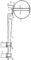
図1に示す給油場設備は、パイプライン4を介して地下タンク3に連結された1対の供給ポンプ1および2を備える。パイプライン4は、ポリエチレン製パイプの連続的に配置された部分品で形成される。パイプライン4は、ポンプ1および2から、タンク3の真上にあるマンホール・チャンバ6内に延びる。チャンバ6は、側壁10および底部12を有するGRP部材8によって画成される。
The oil filling station facility shown in FIG. 1 includes a pair of supply pumps 1 and 2 connected to an underground tank 3 through a pipeline 4. The pipeline 4 is formed of continuously arranged pieces of polyethylene pipe. Pipeline 4 extends from pumps 1 and 2 into a
図1には、パイプライン4からタンク3内に延びる2本のラインが示されている。これらのラインは、燃料供給システムの2つの代替形態に関し、全て揃えるために両方が示されている。実際には、このラインの一方だけが、パイプライン4からマンホール・チャンバ6内に延びるはずである。このラインの1本は、供給ポンプ1および2に吸引ポンプを取り付けた場合に使用される、吸引ライン14である。代替ラインは参照番号16で、タンク3からポンプ1および2へ燃料を推進するように動作可能なポンプ18を介してパイプライン4に連結された圧力ラインである。
In FIG. 1, two lines extending from the pipeline 4 into the tank 3 are shown. These lines are both shown for completeness with respect to two alternative forms of fuel delivery system. In practice, only one of these lines should extend from the pipeline 4 into the
図1からわかるように、パイプライン4がチャンバ6内に通じるように、壁10にアパーチャを設ける必要がある。アパーチャを介した周囲の地中(ここでは参照番号20で示す)からチャンバ6内への水漏れを防止するために、図2〜16により詳細に示されるフィッティング22によって、パイプが円筒形の壁10に封止される。供給パイプから流出または漏れた場合には、このシールによって環境への燃料の漏れも防止される。
As can be seen from FIG. 1, it is necessary to provide an aperture in the
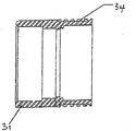
図2には、適当なフィッティング22の参考例がより詳細に示されている。このフィッティングの目的は、フィッティングとチャンバ壁10の間ならびにフィッティングと配管システム4の間に、丈夫で恒久的な流体密封シールを形成することである。フィッティング22は、GRPまたは金属などのGRPに容易に接着可能な材料(ステンレス鋼もしくは被覆した鉄鋼材料、青銅、黄銅もしくは黄銅合金、またはアルミニウムなど)から形成された第1の管状のスリーブ31を備える。重要な特徴は、この材料が、周知の樹脂、接着剤などを使用して、丈夫で、GRP製の壁に実質的に流体密封のシールを形成しなければならないということである。ポリエチレンまたはポリアミドなどのプラスチック材料は一般的に、従来の樹脂または接着剤を使用してGRPに接着するのに優れ、したがって2部品の嵌合に必要である。
In FIG. 2, a reference example of a
スリーブ31は、形状が、パイプ(図示せず)が貫通することができる、長手方向の軸を有するほぼ円筒形である。第2の管状のスリーブ32は、第1の管状スリーブの片端の周りに成型され、ポリエチレン、ポリアミドまたはPVDFなどの配管システムと適合する電気溶融高分子プラスチック材料から形成される。適当な材料については、下記により詳細に説明する。
The
2つのスリーブまたは構成要素の間のシールの流体密封性を改良するために、第1のスリーブの2つのスリーブが重なり合う領域に、一連の溝、スロットまたは稜部34が形成される。第2のスリーブを第1のスリーブの周りに形成するときに、溝にプラスチック材料を充填し、2つの構成要素が使用中に分離するのを防止する。
In order to improve the fluid tightness of the seal between the two sleeves or components, a series of grooves, slots or
第1の管状スリーブの一部分が、第2の管状スリーブの一部分の内部に、2つのスリーブの間に重なり合う領域が存在するようにカプセル化されるのが有利である。第2のスリーブ内部の第1のスリーブのカプセル化部分によって、より丈夫で、経時的漏れの傾向がより低いフィッティングが作られる。 Advantageously, a portion of the first tubular sleeve is encapsulated so that there is an overlapping region between the two sleeves within the portion of the second tubular sleeve. The first sleeve encapsulation within the second sleeve creates a stronger and less prone to leakage over time.
こういったフィッティングは、土壌の収縮、沈下またはその他の動きがあり、供給パイプが故障した場合に燃料が漏れる恐れがある地下など、厳しい環境条件でしばしば使用される可能性があることを銘記されたい。 It is noted that these fittings are often used in harsh environmental conditions, such as underground where there is soil contraction, settlement or other movement and fuel can leak if the supply pipe fails. I want.
必要により、Oリング36などの封止手段を組み込むことによって、2つのスリーブの間のシールをさらに改良することができる。この例のOリングは、どちらかのスリーブの外周をまわる環状のチャネル内に納まる。組み立て中にOリング・シールを第1または第2のスリーブ上に配置できることが理解されよう。容易に組み立てるために、Oリング・シールは通常、第1の管状スリーブの外側表面上の、フィッティング本体内部に位置する端の方に配置される。
If necessary, the seal between the two sleeves can be further improved by incorporating sealing means such as an O-
Oリングを、第1のスリーブの端面37に配置し、第2のスリーブの肩部38と係合させることができることも理解されよう。
It will also be appreciated that an O-ring may be disposed on the
Oリングはフィッティングの内部にあり、その中に密封されるので、非常に長い寿命、少なくともフィッティングの寿命を有することが期待される。 Since the O-ring is inside the fitting and sealed within it, it is expected to have a very long life, at least the life of the fitting.
この例と、やはりOリングを含む以下の例では、Oリングを適当なシーラントのビードと置き換えることができる。シーラントを使用すると、シーラントが接着特性も有し、2つの構成要素同士を接着するのに役立つ点で有利であり得る。シーラントの選択は、その分野の材料の専門家によって行われる。 In this example and the following example, which also includes an O-ring, the O-ring can be replaced with a bead of suitable sealant. The use of a sealant can be advantageous in that the sealant also has adhesive properties and helps to bond the two components together. The choice of sealant is made by material specialists in the field.
第1および第2のスリーブの間のシールの流体密封を強化するために必要に応じて採用される他の特徴がある。第3の管状のスリーブ33が、第1と第2のスリーブが重なり合う領域にあるフィッティングの内側表面に配置される。この第3のスリーブは、ステンレス鋼、被覆した鉄鋼などの金属またはポリマーでできており、その目的は、高分子プラスチック材料の構成要素が、燃料または他の化学物質に曝されたときに縮んだり柔らかくなった場合に、第1のGRPスリーブから外れるのを防止することである。
There are other features that are optionally employed to enhance the fluid tightness of the seal between the first and second sleeves. A third
図3には、整った流線型の外観およびこの組み立て方法から得られる形を示す、フィッティング22の側面図が示されている。基準マーク39によって、電気溶融カップリング(下記参照)を配置し、電気溶融プラスチックでできたフィッティングの端を覆って適切に設置することができる。このマークはまた、フィッティングの端部があいまいな場合にそれを特定する働きもする。
FIG. 3 shows a side view of the fitting 22 showing a clean streamlined appearance and the shape resulting from this assembly method. The
図4には、第1の管状スリーブ31の断面図が示され、スロット34がより詳細に示されている。このGRPの成型が全般に簡易であることは、図4から明らかであろう。スロット34は、多種多様な形状、サイズ、位置および構造をとることができる。不可欠な特徴は、製造中に第2の管状スリーブ構成要素の液体プラスチック材料が流れ込むことができる窪みをそのスロットで作ることである。
FIG. 4 shows a cross-sectional view of the first
組み立ての代替形態では、スロット34は、第1および第2のスリーブが別々に形成され、組み立て中に互いにねじ止めされることができるように、ねじ山の形をとることができる。次いで、化学接着剤または止めねじ(図示せず)を使用して、使用中に2つのスリーブが離れるのを防止することができる。
In an alternative form of assembly, the
図5には、第3の管状スリーブ構成要素の断面が示されている。これを、第2のスリーブが第1のスリーブの周りに形成された後、しかし第2のスリーブの材料がまだ温かく、したがって形成可能な間に、所定の位置にプレスすることができる。 FIG. 5 shows a cross-section of the third tubular sleeve component. This can be pressed into place after the second sleeve is formed around the first sleeve, but while the material of the second sleeve is still warm and thus can be formed.
使用する際は、図8および9を参照すると、フィッティングのGRP部分の端部がチャンバ壁にあるアパーチャを貫通し、一時的に所定の位置に保持される。次いで、GRPバンデージ(図示せず)を使用して、フィッティングを片側または両側のチャンバ壁に封止する。この配置の利点は、フィッティングもチャンバ壁も、丈夫で恒久的な実質的に流体密封のシールを容易に作成することができるような、同じまたは適合性のある材料でできているということである。次いで、従来の方法で必要なゴム製のブーツ55、56を使用して、二次配管システムが使用されるチャンバ内側にシールを形成する。二次的包囲構造が存在する場合、チャンバの外側において、必要に応じてエキスパンダまたはレジューサと共に、電気溶融フィッティングを使用して、二次的に囲われたパイプを収容することができる。 In use, referring to FIGS. 8 and 9, the end of the GRP portion of the fitting passes through an aperture in the chamber wall and is temporarily held in place. A GRP bandage (not shown) is then used to seal the fitting to one or both chamber walls. The advantage of this arrangement is that both the fitting and the chamber wall are made of the same or compatible material that can easily create a durable and permanent substantially fluid-tight seal. . The rubber boots 55, 56 required by conventional methods are then used to form a seal inside the chamber where the secondary piping system is used. If a secondary enclosure is present, an electrically fused fitting can be used outside the chamber, optionally with an expander or reducer, to accommodate the secondary enclosed pipe.
図8では、一次パイプ61も二次パイプ60も、フィッティング22を貫通するようなサイズに形成される。したがって、二次パイプ60は、電気溶融カップリング62、エキスパンダ63および電気溶融カプラ64を介して外部フィッティング22に封止される。一次と二次パイプの間の終端は、ゴム製のブーツ56を使用してチャンバの内部で行われる。
In FIG. 8, both the
図9から、供給パイプ51を含む二次パイプ50がフィッティングの内部直径よりも大きい場合は、フィッティング自体が二次的格納システムの一部分になることが理解されよう。これは、二次パイプ50を事実上フィッティング22の外側に連結する、電気溶融カップリング52、レジューサ53およびカップリング54を使用することによって実現する。これは、本発明の第1の態様によるフィッティングの汎用性の一部を示すものである。
From FIG. 9, it will be appreciated that if the
フランジを備えた、代替かつ好ましいフィッティングが図7に示されている。フランジ40が、フィッティングのGRP構成要素から半径方向に延びる。このフランジは、第1の管状スリーブの組み立て中に一体的に形成することができる。フランジは、アパーチャの封止する領域に、チャンバ壁の形状にあわせて構成される。この例では、このフランジは平面状として示すが、他の形状をもとりうる。
An alternative and preferred fitting with a flange is shown in FIG. A
使用する際は、チャンバ壁に接して所定の位置に固定されたフランジおよびフィッティングに樹脂を塗布し、この樹脂を硬化させる。他の組み立ては上記のとおりである。 In use, a resin is applied to the flange and fitting fixed to a predetermined position in contact with the chamber wall, and the resin is cured. The other assembly is as described above.
電気溶融の1つまたは複数の構成要素は、
ポリエチレンと、
ポリプロピレンと、
ポリ塩化ビニルと、
ポリブチレンと、
ポリウレタンと、
ポリアミド6、6.6、6.10、6.12、11および12を含むポリアミドと、
ポリエチレンテレフタレートと、
ポリブチレンテレフタレートと、
ポリフェニレンサルファイドと、
ポリオキシメチレン(アセタール)と、
エチレンビニルアルコール共重合体と、
ポリフッ化ビニリデン(PVDF)および共重合体と、
ポリフッ化ビニル(PVF)と、
テトラフルオロエチレン−エチレン共重合体(ETFE)と、
テトラフルオロエチレン−ヘキサフルオロエチレン共重合体(FEP)と、
エチレン−テトラフルオロエチレン−ヘキサフルオロプロピレンの三元重合体(EFEP)と、
テトラフルオロエチレン−ヘキサフルオロプロピレン−フッ化ビニリデンの三元重合体(THV)と、
ポリヘキサフルオロプロピレンと、
ポリテトラフルオロエチレン(PTFE)と、
ポリクロロトリフルオロエチレンと、
ポリクロロトリフルオロエチレン(PCTFE)と、
フッ素化ポリエチレンと、
フッ素化ポリプロピレンと、
上記の混合物(ブレンド)およびその共重合体を含む群から選択した1つまたは複数のプラスチック材料から作成されるのが好ましい。
One or more components of electrofusion are:
Polyethylene,
Polypropylene,
Polyvinyl chloride,
Polybutylene,
Polyurethane and
Polyethylene terephthalate,
Polybutylene terephthalate,
Polyphenylene sulfide,
Polyoxymethylene (acetal),
An ethylene vinyl alcohol copolymer;
Polyvinylidene fluoride (PVDF) and a copolymer;
Polyvinyl fluoride (PVF),
Tetrafluoroethylene-ethylene copolymer (ETFE);
Tetrafluoroethylene-hexafluoroethylene copolymer (FEP);
An ethylene-tetrafluoroethylene-hexafluoropropylene terpolymer (EFEP);
Tetrafluoroethylene-hexafluoropropylene-vinylidene fluoride terpolymer (THV);
Polyhexafluoropropylene,
Polytetrafluoroethylene (PTFE);
Polychlorotrifluoroethylene,
Polychlorotrifluoroethylene (PCTFE);
Fluorinated polyethylene,
Fluorinated polypropylene,
Preferably, it is made from one or more plastic materials selected from the group comprising the above blends (blends) and copolymers thereof.
上記の項は、本発明の柔軟性と幅広さを示すものであり、それらを限定するためのものではない。通常は、接合されるパイプに最も適合性があり、かつ問題となっている流体に対する浸透性が最も低いプラスチック材料が、材料の専門家によって選択される。さらに、2個以上のポリマーの混合物を使用することは周知であり、本発明は周知のプラスチック材料の混合物も、まだ開発されていないプラスチック材料の混合物をも包含する。 The above items show the flexibility and breadth of the present invention and are not intended to limit them. Typically, the material specialist selects the plastic material that is most compatible with the pipes to be joined and has the lowest permeability to the fluid in question. Furthermore, it is well known to use mixtures of two or more polymers, and the present invention encompasses both mixtures of known plastic materials and mixtures of plastic materials that have not yet been developed.
GRP樹脂構成要素は、材料の専門家によって選択された適当な任意の熱硬化性樹脂から形成することができる。この樹脂にはポリエステル樹脂またはエポキシ樹脂が含まれるが、これに限定されない。 The GRP resin component can be formed from any suitable thermosetting resin selected by a materials specialist. This resin includes, but is not limited to, a polyester resin or an epoxy resin.
GRPスリーブは、GRPの成型に使用される任意の従来技術で形成することができ、そのような技術には、ハンド・レイアップ、圧縮成型または射出成型が含まれる。本発明はまた、まだ開発されていない成型方法にも適用される。 The GRP sleeve can be formed of any conventional technique used to mold GRP, such techniques include hand layup, compression molding or injection molding. The invention also applies to molding methods that have not yet been developed.
上記の例は、主に単一の壁のチャンバに関する。しかし、本発明によるフィッティングは、2枚のチャンバ壁の間に隙間空間が存在する二重壁のチャンバでも同様に使用することができる。その場合は、フィッティングと外側壁の間、ならびにフィッティングと内側壁の間にシールが形成される。これは、2つのバンデージ(1つはチャンバの外側、1つはチャンバの内側)を使用して、あるいはチャンバ壁の片側または両側をフランジとバンデージにすることによって行うことができる。どちらの場合も、チャンバ壁間の隙間空間の完全性は維持され、それを監視することができる。 The above examples relate primarily to single wall chambers. However, the fitting according to the invention can be used in a double-walled chamber as well, where a gap space exists between the two chamber walls. In that case, seals are formed between the fitting and the outer wall and between the fitting and the inner wall. This can be done using two bandages (one outside the chamber and one inside the chamber) or by making one or both sides of the chamber wall a flange and a bandage. In either case, the integrity of the interstitial space between the chamber walls is maintained and can be monitored.
要約すると、本発明は、電気溶融プラスチック材料から形成されたパイプとGRPチャンバ壁の間に、実質的に流体密封のシールを形成するためのフィッティングを提供する。フィッティングは、パイプと適合性のある電気溶融プラスチック材料から形成された第1の構成要素と、第1の構成要素に実質的に流体密封で接合された第2の構成要素とを含み、第2の構成要素は、GRPチャンバ壁に接着するように適合される。第2の構成要素に関連付けられた1つまたは複数のフランジを、必要に応じて用いてもよい。良好なシールをもたらすには、フランジをチャンバ壁の両側に使用するのが有利である。これは、二重壁のチャンバにシールを形成するときに特に重要である。フランジの一方のみは、フィッティングの一体的部品であってもよい。もう一方のフランジは、ねじ山(下記参照)などの固定手段によって、あるいは樹脂バンデージによって、フィッティングに連結することができる。 In summary, the present invention provides a fitting for forming a substantially fluid tight seal between a pipe formed from an electromelted plastic material and a GRP chamber wall. The fitting includes a first component formed from an electrically molten plastic material compatible with the pipe, and a second component substantially fluid-tightly joined to the first component, the second component The components are adapted to adhere to the GRP chamber wall. One or more flanges associated with the second component may be used as needed. To provide a good seal, it is advantageous to use flanges on both sides of the chamber wall. This is particularly important when forming a seal in a double walled chamber. Only one of the flanges may be an integral part of the fitting. The other flange can be connected to the fitting by fixing means such as threads (see below) or by resin bandage.
フィッティングのプラスチック部分には、一次もしくは二次の、または両方のパイプへの、あるいは別のプラスチックフィッティングへの電気溶融結合を形成するように設計され、適合された、1組または複数の電気溶融巻線および関連端子のセットを組み込むことができる。このプラスチック構成要素を、単純化するため、かつ工具コストを節約するために、このフィッティングをパイプに結合する働きをする別個の電気溶融カップリングの内部表面と、緊密な滑合を形成するように適合することができる。 The plastic portion of the fitting includes a set or sets of electrical melt windings designed and adapted to form an electrical melt bond to the primary or secondary, or both pipes, or to another plastic fitting. A set of wires and associated terminals can be incorporated. To simplify and save tool costs, this plastic component forms a close slip with the internal surface of a separate electromelt coupling that serves to couple the fitting to the pipe. Can fit.
図10および11には、本発明の他の実施形態によるフィッティングが示されている。この実施形態では、フィッティング122は、2つの別々の構成要素である、プラスチックフィッティング131および金属製のフランジ型フィッティング133からなる第1の部分124と、第2の構成要素すなわち部分140とを備える。
10 and 11 show a fitting according to another embodiment of the present invention. In this embodiment, the fitting 122 comprises two separate components, a
まず部分124に移ると、フィッティング131のプラスチック部分は全般に管状のスリーブからなり、スリーブの一方の端である第1の端132は、一次パイプ118の外側を覆って緊密に滑合する内径を有する。それに対向するスリーブの端、すなわち第2の端134は、二次パイプ119の外側を覆って緊密に滑合する内径を有する。したがって、フィッティング131のプラスチック部分は形状が全般に、一次パイプがその本体全体を貫通できる長手方向の軸を有する、断面の不均一な円筒形である。二次パイプは、この長手方向の軸に沿って、フィッティングの一方の端のみから入ることができ、フィッティングの内径が縮小することによって停止する一定の点まで通過することができる。
Turning first to
構成要素131の内側表面144は、エネルギー伝達手段、この場合はプラスチック構成要素131の内部表面の近傍、またはそこに位置する電気電熱線の巻線146を収容する。これらの巻線は、プラスチック構成要素131から突出する端子ピン147、148に、電気的に接続される。端子ピン147、148は、プラスチック構成要素131から突出し、それと一体的な中空の円筒形プラスチック端子カバー149、150で覆うことができる。このタイプの電熱線をプラスチックフィッティングの内側表面に配置する方法は、周知である。
The
電気溶融巻線をフィッティング自体に組み込むことは必須ではない。フィッティングのプラスチック構成要素を、単純化するため、かつ工具コストを節約するために、このフィッティングをパイプに結合する働きをする別個の電気溶融カップリングの内部表面と、緊密な滑合を形成するように適合することができる。必要に応じて、1つまたは複数のゴム製のブーツを、フィッティングの電気溶融結合部と対向する側に使用することができる。 It is not essential to incorporate the electric melt winding into the fitting itself. In order to simplify the plastic component of the fitting and to save tool costs, it forms a tight slip with the internal surface of the separate electromelt coupling that serves to couple the fitting to the pipe. Can be adapted. If desired, one or more rubber boots can be used on the side of the fitting opposite the electrofusion joint.
フィッティングの第1の部分の組み立てを完成させるには、製造中に、プラスチックフィッティング131の、二次パイプを収容するように適合された端部の外側の周りに、フランジ付き金属フィッティング133が実質的に流体密封の形で接合される。フィッティング133のこの金属部分は、二次パイプを収容するように適合されたフィッティングの端部の外部表面にねじ山が設けられた、全般に管状の領域136を備える。フランジ137が、管状の領域136から半径方向外向きに延び、その一方の表面は、チャンバ壁の表面に合わせた形状をとり、それと係合するように適合されている。したがって、フランジは、チャンバの側部が平坦の場合は平坦に、あるいはチャンバが湾曲した壁を有している場合は湾曲し得る。
To complete the assembly of the first part of the fitting, a
上記のねじ山構造は、フィッティングの第1および第2の部分を互いに固定するため、ならびにそれらをチャンバ壁の両側でしっかりと固定するための、固定手段として機能する。ボルトまたは他の固定手段など、様々な固定手段を使用することもできる。 The above thread structure serves as a securing means for securing the first and second parts of the fitting to each other and for securing them firmly on both sides of the chamber wall. Various fixing means can also be used, such as bolts or other fixing means.
この例では、金属構成要素は、プラスチック構成要素を覆って圧着、すなわち内側に加締められ、肩部137と圧着片138の間の所定の位置に保持される。適当な金属には、ステンレス鋼、被覆した鉄鋼、アルミニウム、青銅、黄銅または黄銅合金が含まれる。
In this example, the metal component is crimped over the plastic component, ie, crimped inward, and held in place between the
2つの構成要素間のシールの流体密封性を改良するために、一連の溝、スロットまたは稜部(図示せず)を、2つのスリーブが重なり合う領域に形成することができる。接合部を形成するときに、こういった溝にプラスチック材料を充填させ、2つの構成要素が使用中に分離するのを防止する。 To improve the fluid tightness of the seal between the two components, a series of grooves, slots or ridges (not shown) can be formed in the area where the two sleeves overlap. When forming the joint, these grooves are filled with plastic material to prevent the two components from separating during use.
任意選択で、Oリングまたはシーラント・ビード(図示せず)などの封止手段を組み込むことによって、2つのスリーブの間のシールをさらに改良することができる。Oリングまたはシーラントは、どちらかのスリーブの周辺部の周りにある環状のチャネル内に納まる。Oリング・シール/シーラントは、組み立て中に、第1または第2のスリーブ上に配置できることが理解されよう。容易に組み立てるために、Oリング・シール/シーラントは通常、プラスチック管状スリーブの外側表面上の、フィッティング本体内部に位置する端の方に配置される。 Optionally, the seal between the two sleeves can be further improved by incorporating sealing means such as O-rings or sealant beads (not shown). The O-ring or sealant fits in an annular channel around the periphery of either sleeve. It will be appreciated that the O-ring seal / sealant can be placed on the first or second sleeve during assembly. For ease of assembly, the O-ring seal / sealant is typically placed on the outer surface of the plastic tubular sleeve toward the end located inside the fitting body.
この封止手段を、第1のスリーブの端面139に配置し、第2のスリーブの肩部135と係合させることができることも理解されよう。
It will also be appreciated that this sealing means may be disposed on the
Oリング・シールはフィッティングの内部にあり、その中に密封されるので、非常に長い寿命、少なくともフィッティングの寿命を有することが期待される。 Since the O-ring seal is internal to the fitting and sealed therein, it is expected to have a very long life, at least the life of the fitting.
フィッティング140の第2の部分は、内部ねじ山143を有する、全般に管状の構成要素142を備える。この構成要素のねじ山の直径、サイズ、形状、深さおよびピッチは、この第2の部分が、対応する第1の構成要素の金属部分の端部を覆ってその上にねじ山を設けることができるように設計されている。この第2の部分はまた、径方向に延びるフランジ145も有する。
The second portion of the fitting 140 comprises a generally
フランジ145は、図11でより詳細にわかる。フランジの面は、一連のアパーチャによって穴があいている。アパーチャまたは窪み160は、フランジを工具と係合させて、回転させ、チャンバ壁に対して締め付けるために、組み立て中に設けられる。樹脂がフランジの本体の中を通り抜けて、フランジと壁の間の接着強度を増すことができるように、切り抜き(cut out)すなわちスロット160が設けられる(下記参照)。
The
フランジに回転用の手掛かり(purchase)を設けるために、様々な他の形状および装置を使用することができる。一方または両方の部分の両側に、スパナ、レンチまたは特殊工具を使用できるような平坦部分を含んでもよい。あるいはフランジに、必要な手掛かりを得るために使用できる突出部または切り抜きを組み込んでもよい。 Various other shapes and devices can be used to provide a purchase for rotation on the flange. A flat portion may be included on either side of one or both portions such that a spanner, wrench or special tool can be used. Alternatively, the flange may incorporate protrusions or cutouts that can be used to obtain the necessary clues.
使用する際には、フィッティングの第1の部分124を、通常チャンバの内側から、チャンバ壁に対して平らに係合するまで、チャンバ壁の事前穿設済みの穴に通す。ただし、これを行う前に、GRP樹脂、ガラス繊維マットまたは他の接着剤を、フランジの面もしくはアパーチャの周りのチャンバ壁、またはその両方に塗布する。同様の接着剤を、チャンバの外側のフランジ/チャンバ壁に塗布する。あるいは、フランジをチャンバ壁に対してクランプで堅固に固定してもよく、樹脂または他の適当な接着剤を、フランジおよび周囲の領域のほぼ完全に露出した表面一面にわたって塗布してもよい。これによっても、丈夫な流体密封シールがもたらされる。
In use, the
他の代替方法では、フランジの両面は、フランジとチャンバ壁の間にも、フランジの外部に露出した面にも、樹脂/接着剤を塗布してもよい。 In another alternative, the resin / adhesive may be applied to both surfaces of the flange, either between the flange and the chamber wall, or on the exposed surface of the flange.
次いで、フィッティング126の第2の部分を、チャンバ壁を通って延びる第1のフィッティングのねじ山部分にねじ込み、接着剤が硬化すると流体密封シールを形成するように、この2つのフィッティングの部分をチャンバ壁に締め付ける。 The second portion of the fitting 126 is then screwed into the thread portion of the first fitting that extends through the chamber wall, and the two fitting portions are combined into the chamber so that when the adhesive is cured, a fluid tight seal is formed. Tighten to the wall.
次いで、一次および二次パイプを図10に示すようにフィッティングに通し、一次パイプも二次パイプもフィッティングに封止するように、巻線146に電流を通す。 The primary and secondary pipes are then passed through the fitting as shown in FIG. 10, and current is passed through the winding 146 so that both the primary and secondary pipes are sealed to the fitting.
この金属製の内部終端フィッティングは、製造の際に、レジューサフィッティングの内側に圧着されることは前述の説明から理解されよう。現場では、完全な内部フィッティングを穴に通し、外部フランジを所定の位置にねじ止めしてフィッティングを固定する。次いで、樹脂およびガラス繊維マットを使用して、金属フランジをサンプの壁に接着する。次いで、一次および二次パイプを電気溶融によって結合させることができる。 It will be understood from the foregoing description that this metal internal termination fitting is crimped inside the reducer fitting during manufacture. In the field, the complete internal fitting is threaded through the hole and the external flange is screwed into place to secure the fitting. The metal flange is then bonded to the sump wall using a resin and glass fiber mat. The primary and secondary pipes can then be joined by electromelting.
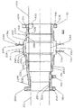
図12、13および14には、参考例が示されている。この参考例では、フィッティング222は3つの部分、第1の部分230と、第2の部分231と、第3の部分232を備える。明らかにしておくが、下記の複数構成要素のシステムでは、アイテム231は請求項1の「第1の部分」と呼ばれるアイテムに対応し、アイテム230および232は、それぞれ「第2の部分」および「第3の部分」アイテムに対応する。
Reference examples are shown in FIGS. 12, 13 and 14. In this reference example , the fitting 222 includes three parts, a
まず部分230に移ると、第1の端233は、二次パイプ234の外側を覆って緊密に滑合する内径を有する。したがって、部分230は形状が全般に、二次パイプがその本体全体を貫通できる長手方向の軸を有する、断面の不均一な円筒形である。
Moving first to
この参考例では、第1の部分230および第3の部分232は、少なくともそれらの内側表面が、その間に実質的に流体密封のシールを形成するために、一次および二次パイプの外側表面に電気溶融可能であるようなプラスチック材料から形成される。部分230の内側表面236は、エネルギー伝達手段、この場合は部分230の内部表面の近傍、またはそこに位置する電気電熱線の巻線237を収容する。これらの巻線は、プラスチック部分230から突出している端子ピン238、239に電気的に接続される。端子ピン238、239は、部分230から突出し、それと一体的な中空の円筒形プラスチック端子カバー240、241で覆うことができる。このタイプの電熱線をプラスチックフィッティングの内側表面に配置する方法は、周知である。
In this reference example , the
フィッティングの第1の部分は、製造中に第2の部分231にほぼ流体タイプの形で接合される。部分231は一般的に金属で製造されるが、ねじ山を保持し、かつ相補的ねじ山部材と係合するのに十分な強度のある任意の材料から製造することができる。この例では、第2の部分231は金属製で、第1の部分に圧着される、すなわち外側に加締められる243。外向きに延びるフランジすなわちフック242が第1の部分230の肩部すなわち段部258と係合して、その間の接合が行われると、第1の部分230の横方向または軸方向の動きが防止され、その2つの構成要素が互いに接合されると、より高い強度および安定性がもたらされる。第2の部分231は、プラスチック構成要素230の任意の動きに抵抗するように、径方向または長手方向にスロットを形成することができる。2つの構成要素の間のシールの流体密封性を改良するために、一連の溝、スロットまたは稜部(図示せず)を、2つのスリーブが重なり合う領域に形成することができる。接合部を形成するときに、こういった溝にプラスチック材料を充填し、2つの構成要素が使用中に分離するのを防止する。
The first part of the fitting is joined to the
任意選択で、Oリングまたはシーラントのビード(図示せず)などの封止手段を組み込むことによって、2つのスリーブの間のシールをさらに改良することができる。Oリングは、どちらかの部分の周辺部の周りにある環状のチャネル内に納まる。Oリング・シールは、組み立て中に、第1または第2の部分上に配置できることが理解されよう。容易に組み立てるために、Oリング・シールは通常、第1の部分の外側表面上の、フィッティング本体内部に位置する端の方に配置される。 Optionally, the seal between the two sleeves can be further improved by incorporating a sealing means such as an O-ring or a bead of sealant (not shown). The O-ring fits in an annular channel around the periphery of either part. It will be appreciated that the O-ring seal can be placed on the first or second portion during assembly. For ease of assembly, the O-ring seal is typically placed on the outer surface of the first part toward the end located within the fitting body.
この封止手段を、第1の部分の端面に配置し、第2の部分の肩部と係合できることも理解されよう。 It will also be appreciated that this sealing means can be disposed on the end face of the first part and engage the shoulder of the second part.
この封止手段はフィッティングの内部にあり、その中に密封されるので、非常に長い寿命、少なくともフィッティングの寿命を有することが期待される。 Since this sealing means is inside the fitting and is sealed therein, it is expected to have a very long life, at least the life of the fitting.
第2の部分231は、空間244をとり残す、あるいは他の参考例として、二次パイプ234の外側を覆って緊密に滑合する、二次パイプ234を収容できる内径を有する。どちらの場合にも、第2の部分231の内側表面と二次パイプの外側の間に、その空間が目で見えなくても、何らかの形の空間が存在する。
The
第2の部分の外側表面245は、ねじ山領域248、249によって、1つまたは複数の径方向に延びるフランジ246、247を収容するように適合されている。フランジの内部直径は、相補的なねじ山領域を備えるように適合されている。他の参考例では、フランジ246、247の一方が部分231の一体的部品であってもよい。
The outer surface 245 of the second portion is adapted to receive one or more radially extending
フランジ246、247は、チャンバ壁の表面と共形になり、それと係合するように適合されている。したがって、フランジは、チャンバの側部が平坦の場合は平坦に、あるいはチャンバが湾曲した壁を有している場合は湾曲し得る。
The
この構成要素のねじ山の直径、サイズ、形状、深さおよびピッチは、このフランジが、対応する第2の部分の端部を覆ってその上にねじ山を設けることができるように設計されている。 The thread diameter, size, shape, depth and pitch of this component are designed so that this flange can cover the end of the corresponding second part and provide a thread on it. Yes.
フランジ246、247の典型的な例は、図14でより詳細にわかる。フランジの面は、一連のアパーチャによって穴があいている。アパーチャすなわち窪み270、272は、フランジを工具と係合させて、回転させ、チャンバ壁に対して締め付けるように組み立て中に設けられる。樹脂が使用するフランジの本体の中を通り抜けて、フランジと壁の間の接着強度を増すことができるように、切り抜きすなわちスロット271が設けられる(下記参照)。
A typical example of the
フランジに回転用の手掛かりを設けるために、様々な他の形状および装置を使用することができる。一方または両方の部分の両側に、スパナ、レンチまたは特殊工具を使用できるような平坦部分を含んでもよい。あるいはフランジに、必要な手掛かりを得るために使用できるハンドル、突出部または切り抜きを組み込んでもよい。 A variety of other shapes and devices can be used to provide rotating cues on the flange. A flat portion may be included on either side of one or both portions such that a spanner, wrench or special tool can be used. Alternatively, the flange may incorporate a handle, protrusion or cutout that can be used to obtain the necessary clues.
均一な断面を有するフランジが示されている。ただし、フランジには、そのねじ山領域を延ばすために、フランジの中心アパーチャの周りに延び、かつフィッティングに沿って長手方向に延びるカラー(図示せず)を組み込むことができる。次いで、上記カラーのほぼ内側表面全体にねじ山を設けることができる。 A flange having a uniform cross section is shown. However, the flange can incorporate a collar (not shown) that extends around the central aperture of the flange and extends longitudinally along the fitting to extend its threaded region. A thread may then be provided on substantially the entire inner surface of the collar.
図14を参照すると、窪み272が事実上、フランジの外側周囲縁部の城郭状片になっている。これらの城郭状片は、その数、フランジ周囲の周りのそれらの間隔、およびそれらがフランジの本体の中に延びる範囲が変動してもよく、2つの目的に役立つ。第1に、それによって、フランジを回転させ、チャンバ壁に対して締め付けるために、工具をフランジと係合させることが可能になる。第2に、それが樹脂で覆われたときに、フィッティングとGRPチャンバ壁の間の接着が著しく強化される。したがって、フランジの面の中を通って延びるアパーチャを有することではなく、単に城郭状片すなわち窪みをフランジの縁部に有することが必須になる。
Referring to FIG. 14, the
フランジの一方を(両方ではない)、第2の部分231の一体的部品として形成してもよい。これによって、フィッティングの強度は増強されるが、フィッティングをチャンバ壁のアパーチャに片方向だけにしか通すことができないことになる。
One (but not both) of the flanges may be formed as an integral part of the
第2の部分231はまた、製造中に、第3の部分232に実質的に流体密封の形で接合される。やはり、この例では、第2の部分は、肩部242’と圧着243’の間の所定の位置に保持される第3の部分を覆って圧着、すなわち外側に加締められる。第2と第3の部分の間の接合は、図12および13に示されている上記の第1と第2の部分の間の接合と、本質的に同様である。
The
第3の部分232は、二次パイプ234との緊密な滑合を形成するように適合することができる第1の領域250を備える。二次パイプは、第3の部分に沿って、一方の端のみから入ることができ、フィッティングの内径が縮小することによって停止する一定の点まで通過することができる。部分232の内側表面251は、エネルギー伝達手段、この場合は第3の部分232の第1の領域250の内部表面の近傍、またはそこに位置する電気電熱線の巻線252を収容する。これらの巻線は、プラスチック部分232から突出している端子ピン253、254に、巻線の第2のセット(下記参照)と直列に電気的に接続される。
The third portion 232 includes a
第3の部分232はさらに、一次パイプ235との緊密な滑合を形成するように適合された第2の領域255を備える。第3の部分232の第2の領域255の内側表面256は、エネルギー伝達手段、この場合は第3の部分232の第2の領域255の内部表面の近傍、またはそこに位置する電気電熱線の巻線257を収容する。これらの巻線も、プラスチック部分232から突出している端子ピン253、254に電気的に接続される。したがって、端子ピン253、254が作動すると、エネルギー伝達手段252も、257も作動し、一次パイプ235へも、二次パイプ234へも融解する。
The third portion 232 further comprises a
他の参考例では、巻線252および257を別々の端子ピンの対に接続してもよい。このように配置することによって、二次および一次パイプに対する電気溶融結合を、別々の操作で形成することが可能になるはずである。
In other reference examples ,
ねじ山領域248、249は、フランジ246、247を第2の部分上に固定するための、ならびに使用する際にそれらをチャンバ壁の両側にしっかりと固定するための、固定手段として機能する。ボルトまたは他の固定手段など、様々な固定手段を使用することができる。
The threaded
使用する際は、第1のフランジ246を、二次パイプ234がすでに所定の位置にあればそれに被せて摺動させる。次いで、第1の部分230、第2の部分231および第3の部分232を備えるフィッティングを、通常チャンバの内側からチャンバ壁の事前穿設済みの穴に通す。次いで、フランジ246を摺動させて戻し第1の部分に被せ、フランジがチャンバ壁に対して平らに係合するまで、チャンバ壁の中を通って延びる第2の部分のねじ山領域249の上にねじ込む。
In use, the
ただし、これを行う前に、GRP樹脂、ガラス繊維マットまたは他の接着剤を、フランジの面もしくはアパーチャの周りのチャンバ壁、またはその両方に塗布する。同様の接着剤を、チャンバの外側のフランジ/チャンバ壁に塗布する。あるいは、フランジをチャンバ壁に対してクランプで堅固に固定してもよく、樹脂または他の適当な接着剤を、フランジおよび周囲の領域のほぼ完全に露出した表面一面にわたって塗布してもよい。これによっても、丈夫な流体密封シールがもたらされる。 However, before doing this, GRP resin, glass fiber mat or other adhesive is applied to the flange face or the chamber wall around the aperture, or both. A similar adhesive is applied to the outer flange / chamber wall of the chamber. Alternatively, the flange may be securely clamped to the chamber wall and a resin or other suitable adhesive may be applied over the flange and the surrounding area, almost completely exposed. This also provides a strong fluid tight seal.
他の代替方法では、フランジの両面は、フランジとチャンバ壁の間にも、フランジの外部に露出した面にも、樹脂/接着剤を塗布してもよい。 In another alternative, the resin / adhesive may be applied to both surfaces of the flange, either between the flange and the chamber wall, or on the exposed surface of the flange.
次いで、第2のフランジ247を、第2の部分のねじ山領域248にねじ込み、接着剤が硬化すると流体密封シールを形成するように、この2つのフランジをチャンバ壁に締め付ける。
The
次いで、一次および二次パイプを図12に示すようにフィッティングに通し、一次パイプも二次パイプもフィッティングに封止するように、巻線237、252および257に電流を通す。
The primary and secondary pipes are then passed through the fitting as shown in FIG. 12, and current is passed through the
上述の、材料の専門家によって選択された多種多様なプラスチック材料から、このタイプのフィッティングのプラスチック部分を形成できることが容易に理解されよう。 It will be readily appreciated that the plastic portion of this type of fitting can be formed from a wide variety of plastic materials, selected by material specialists as described above.
本発明によるフィッティングが、2枚の壁の間に、丈夫で恒久的な実質的に流体密封のシールを容易に形成できるような、チャンバ壁と同じ材料、またはチャンバ壁と適合性のある材料でできた一部分を備えることも理解されよう。このフィッティングはまた、1つ、または任意選択で2つの、電気溶融可能なプラスチック材料でできた、他の部分も備える。かかる部分が2つ設けられる場合は、それらは、パイプがフィッティングをその長手方向の軸に沿って貫通できるように、第1の部分の両側に配置される。フランジは、第1の部分から径方向外向きに延びるのが好ましい。第1の部分は、製造中に、他の部分に実質的に流体密封の形で接合される。 The fitting according to the present invention is made of the same material as the chamber wall or a material compatible with the chamber wall so that a durable and permanent substantially fluid-tight seal can be easily formed between the two walls. It will also be understood that it comprises a portion that is made. The fitting also comprises other parts made of one or optionally two, electromeltable plastic materials. If two such parts are provided, they are arranged on both sides of the first part so that the pipe can penetrate the fitting along its longitudinal axis. The flange preferably extends radially outward from the first portion. The first part is joined to the other part in a substantially fluid-tight manner during manufacture.
本発明によるフィッティングは、単一のまたは二重の壁のチャンバで同様に使用することができる。壁の両側にシールが形成されるので、二重壁のチャンバにあるチャンバ壁同士の間の間隙領域の完全性は維持され、それを監視することができる。かかるフィッティングは、パイプと、図1のサンプ68および70などのサンプの壁との間に、シールを形成するために、同様に使用することができる。
The fitting according to the invention can be used in a single or double wall chamber as well. Since seals are formed on both sides of the wall, the integrity of the gap region between the chamber walls in the double-walled chamber is maintained and can be monitored. Such fittings can similarly be used to form a seal between the pipe and the wall of a sump such as
二次パイプ234の外側表面と第2の部分の内側表面の間に形成された空間244を監視することが可能である。格納チャンバの壁が二次的に囲われている場合、空間244を格納チャンバの壁の間隙領域と接続するために、第2の部分に穴259を穿設することができる。その場合、壁の間隙領域を監視するのと同時に、空間244、したがってフィッティング全体を監視することが可能である。
It is possible to monitor the
この説明では、パイプという用語は全般に、円形断面のパイプを示す。ただし、本発明はまた、箱形断面、波形などの他の断面を有するパイプも包含し、さらに単一の壁または二次的に囲われたパイプも包含する。 In this description, the term pipe generally refers to a circular cross-section pipe. However, the present invention also encompasses pipes having other cross-sections such as box-shaped cross-sections, corrugations, etc., and also includes single walls or secondary enclosed pipes.
図15に示す他の参考例では、一次パイプ435と壁408(例えば、チャンバまたはサンプの壁)の間のカップリングは5つの主要構成要素、すなわち第1のカップリング部分430、第1の中間部材440、第2のカップリング部分450、第2の中間部材460、および第3のカップリング部分470を備える。第1のカップリング部分430、第1の中間部材440、第2の中間部材460および第3のカップリング部分470は、1つまたは複数の電気溶融可能なプラスチック材料でできており、その例は上記に与えられている。
In another reference example shown in FIG. 15, the coupling between the
明らかにしておくが、この例で説明する複数構成要素のシステムでは、アイテム450は請求項1の表現の「第1の部分」と呼ばれるアイテムに対応し、アイテム460および440は、それぞれ「第2の部分」および「第3の部分」アイテムに対応する。
For clarity, in the multi-component system described in this example, item 450 corresponds to an item called the “first part” of claim 1, and
図に示すように、この例では、壁408は二重壁410、412を備え、その間に隙間空間414を有する。
As shown in the figure, in this example, the
二次的に囲われたパイプ組立体が、二次パイプ434内部に含まれる一次供給パイプ435を備え、その間に隙間空間を有し、図の左側から壁408に接近している。一次パイプ435は、壁408のアパーチャを貫通し、図の右側に向かって延びる。追加の配管436が、一次パイプ435に連結される可能性のある他の配管の例として示されている。
The secondary enclosed pipe assembly includes a
第1のカップリング部分430は、二次パイプ434が第1のカップリング430内に通じるように構成され、かつ二次パイプ434がほぼ中央を第1のカップリング430の長さに沿って延びるように配置されている。第1のカップリング430は、二次パイプ434の外部表面の周りに緊密な滑合を形成するように適合された第1の部分438と、第1の中間部材440に結合するように適合された第2の部分439を備える。二次パイプ434が突き当たるための、稜部、突出部または止め具433(環状でもよい)を設けてもよい。この止め具433によって、二次パイプ434を第1のカップリング430内部に挿入することができる範囲が決まり、二次パイプ434を止め具433に押し付けて完全に挿入すると、確実に、満足のいくフィッティングを形成するのに十分なほどパイプが中に入る。第1のカップリング430はさらに、領域438および439内に、端子431および432に電気的に接続されたエネルギー伝達手段(例えば、電気溶融巻線(図示せず))を備える。
The
第3のカップリング部分470は、一次パイプ435の外部の周りに緊密な滑合を設けるように適合された部分474を備える。第3のカップリング470の内径は、第2の中間部材460に結合するように適合された第2の部分476を設けるために広くなる。第3のカップリング470は、領域474および476内に、端子471、472に電気的に接続されたエネルギー伝達手段(例えば、電気溶融巻線(図示せず))を備える。
The
第2のカップリング部分450は、壁408に設けられたアパーチャ内部に配置されるように適合され、第2のカップリング450と壁408の間に流体密封接続を形成するように適合される。参考例では、この第2のカップリング450は黄銅でできているが、燃料に対して耐性があり、かつ壁の材料に接着または接合できる他の金属またはプラスチック材料を、その代わりに使用してもよい。GRPは、もう1つの適当な材料である。
The second coupling portion 450 is adapted to be disposed within an aperture provided in the
第2のカップリング450は、第1の一体的部材451、452、453、454、458と、第2の、最初は別個のフランジすなわちカラー457とを備える。フランジすなわちカラー457は、第1の部材451、452、453、454、458上に設けられた、対応するねじ山または取り付け手段に取り付けることができるように、ねじ山(または代替の取り付け手段)を備えるのが好ましく、その構造が図に示されている。第1の部材上のねじ山(領域453に隣接)は、取り付けのときに、壁408の片側のほうに、壁の穴と干渉しないように配置される。
The second coupling 450 comprises a first
封止手段としての任意選択のOリングすなわちシーラント・ビード455、456を、この封止手段が流体密封シールを形成する、あるいは壁410、412の外部表面と共にそれを高めるように、領域458の内側表面上、ならびにカラーすなわちフランジ457の内側表面上に設けることができる。
An optional O-ring or sealant bead 455, 456 as a sealing means is placed inside
さらに、取り付けのときに、壁408内部の隙間空間414が第2のカップリング450と一次パイプ435の外部の間の間隙416と流体連通するように、穴すなわちアパーチャ459を、領域451と452の間の点から第2のカップリング450を通って領域458とカラー457の間の点まで設けることができる。
In addition, the holes or apertures 459 are placed in the regions 451 and 452 such that the
第2のカップリング450は、第1の中間部材440を領域451と453の間に配置できるように、ならびに第2の中間部材460を領域452と454の間に配置できるように構成される。第2のカップリング450の製造中、または取り付け中に、第1の中間部材440が領域451と453の間に挿入され、第2の中間部材460が領域452と454の間に挿入され、領域453、454は、中間部材440、460を把持するように加締められ、あるいはその他の方法で変形される。
The second coupling 450 is configured such that the first
取り付けする間、第2のカップリング450(第1、第2の中間部材440、460が取り付けられている)は、領域451が壁408を貫通するように、図に示す壁の右側から左の方向に、壁408のアパーチャ内に挿入される。(Oリング456を使用する場合は、それが領域458の所定の位置に事前に載せられているはずである。)第2のカップリング450は、領域458(およびOリング456)が壁412の外側表面に隣接するまで操作される。次いで、カラーすなわちフランジ457(所定の位置にあるOリング455を使用する場合はそれと共に)は、それが壁410の外側表面と同じ平面になるまで、領域453に被せて所定の位置にねじ込まれ、図に示す構造になる。次いで、GRP接着、接着剤または他のシーラント490、491が、第2のカップリング450のフランジ457および領域458の周り、ならびに第2のカップリング450の周り全般に塗布され、壁410、412と、領域457および458と、第1、第2の中間部材440、460上の領域453、454とに重なり、それによって第2のカップリング450と壁408の間に流体密封シールが得られる。
During installation, the second coupling 450 (with the first and second
次いで、第1のカップリングの部分439が中間部材440と密着嵌合するように、第1のカップリング430が第1の中間部材440の周りに配置される。
The
次いで、一次パイプ435が差し込まれて第1のカップリング430を通り、続いて第2のカップリング450を通り抜ける。二次パイプ434が、第1のカップリング430内の止め具433のところまで差し込まれる。
The
次いで、領域476が第2の中間部材460の周りに配置され、かつ領域474が一次パイプ435の周りに緊密な滑合を形成するように、図の右側から、第3のカップリング470が差し込まれる。
The
さらに、第1のカップリング430および第3のカップリング470に組み込まれたエネルギー伝達手段が、端子431および432と、端子471および472に電源供給を接続することによってエネルギー供給される。これによって、第1のカップリング430の領域438と二次パイプ434の外部の間と、第1のカップリング430の領域439と第1の中間部材440の間と、第3のカップリング470の領域476と第2の中間部材460の間と、第3のカップリング470の領域474と一次パイプ435の外部の間とに、流体密封式の電気溶融連結が形成される。
Further, the energy transmission means incorporated in the
第1、第2および第3のカップリング(430、450、470)と、第1および第2の中間部材(440、460)が取り付けられると、二次カップリング450の下の間隙416が、一次パイプ435と二次パイプ434の間の隙間空間と流体連通する。穴すなわちアパーチャ459が壁の隙間空間414と間隙416の間に設けられると、一次パイプ435と二次パイプ434の間の隙間空間と隙間空間414が流体連通する。
When the first, second and third couplings (430, 450, 470) and the first and second intermediate members (440, 460) are attached, the gap 416 under the secondary coupling 450 is It is in fluid communication with the gap space between the
図16には、第1のカップリング部分530と、第2のカップリング550と、第3のカップリング部分570を備えるフィッティングの他の参考例が示されている。一次パイプ435、二次パイプ434および壁408の配置は、上記の図15と同様である。
FIG. 16 shows another reference example of the fitting including the first coupling portion 530, the
第1のカップリング部分530、第2のカップリング部分550および第3のカップリング部分570は、1つまたは複数の電気溶融可能なプラスチック材料でできており、その例は上記に与えられている。
The first coupling portion 530, the
第1のカップリング部分530は、領域538および539を備え、そのそれぞれが、電気端子531および532に接続された、電気溶融巻線(図示せず)などのエネルギー伝達手段を組み込む。領域538の内部表面は、二次パイプ434の外部と緊密な滑合を形成するように構成される。図15の参考例と同様に、二次パイプ434が突き当たるための、突出部、稜部または止め具533が設けられる。
The first coupling portion 530 includes
第3のカップリング部分570は、一次パイプ435の外部と緊密な滑合を形成するように適合された第1の領域574と、第2のカップリング部分550と結合するように適合された第2の領域576とを備える。領域574および576は、電気端子571および572に接続された、電気溶融巻線(図示せず)などのエネルギー伝達手段を組み込む。
The third coupling portion 570 is adapted to couple with the
ここで、第2のカップリング部分550は、電気溶融可能なプラスチック材料でできた単一部材551、552、558を備える。事実上、この単一部材は、図15の第2のカップリング部分450の領域451、452、453、454および458と組み合わせた、図15の参考例にある第1および第2の中間部材(440、460)と等価である。ただし、この参考例では、別個の中間部材(上記の440および460)すなわち加締め(例えば、上記の領域453および454のもの)を必要とすることなく、第1および第3のカップリング部分530、570を、電気溶融可能な材料で形成することによって、第2のカップリング550に電気溶融結合を使用して直接結合することができる。
Here, the
別個のねじ山付きのフランジすなわちカラー557が、第2のカップリング部分550の外側表面553上に設けられた対応するねじ山と係合するように適合される。表面553上のねじ山は、取り付けのときに、壁408の片側のほうに、壁の穴と干渉しないように配置される。シーラント・ビードすなわちOリング555、556などの任意選択の封止手段は、上記の通り含むことができる。図16を参照すると、カラー557を第2のカップリング550に取り付ける機構は、第2のカップリング550の表面553上に設けたねじ山とカラーが係合するように、カラー557を左側から右方向に差し込むものである。カラー557および表面553に組み込まれたねじ山を、これらの構成要素の一体的部品として成型してもよく、あるいは当業者には周知のタッピング技術を使用して、後で形成してもよい。ねじ山付きプラスチック構成要素の製造関連の制限により、フランジすなわちカラー557の厚さは、図16に示すものよりも厚くなってもよい。
A separate threaded flange or
取り付ければ、壁408内部の隙間空間414が第2のカップリング部分550と一次パイプ435の外部との間の間隙516と流体連通するように、穴すなわちアパーチャ559を第2のカップリング部分550を貫通して設けることもできる。
When installed, a hole or
取り付けする間、第2のカップリング550は、領域551が壁408を貫通するように、図16に示す壁の右側から左の方向に、壁408のアパーチャ内に挿入される。(Oリングすなわちシーラント・ビード556を使用する場合は、それが領域558の所定の位置に事前に載せられているはずである。)第2のカップリング550は、領域558(およびOリング556)が壁112の外側表面に隣接するまで操作される。次いで、図に示すように、カラーすなわちフランジ557(所定の位置にあるOリング555を使用する場合はそれと共に)は、それが壁410の外側表面と同じ平面になるまで、領域553に被せて所定の位置にねじ込まれる。次いで、GRP接着、接着剤または他のシーラント590、591が、第2のカップリング550のフランジ557および領域558の周り、ならびに第2のカップリング550の周り全般に塗布され、壁410、412に重なり、それによって第2のカップリング550と壁408の間に流体密封シールが得られる。
During attachment, the
次いで、第1のカップリングの領域539が第2のカップリング550の領域551と密着嵌合するように、第1のカップリング530を所定の位置まで移動させる。
Next, the first coupling 530 is moved to a predetermined position so that the first coupling region 539 is in close contact with the
次いで、一次パイプ435が差し込まれて、第1のカップリング530を通り、続いて第2のカップリング550を通り抜ける。二次パイプ434が、第1のカップリング530内に止め具533のところまで差し込まれる。
The
次いで、領域576が第2のカップリング550の領域552の周りに配置され、かつ領域574が一次パイプ535の周りに緊密な滑合を形成するように、図の右側から、第3のカップリング570が差し込まれる。
From the right side of the figure, the third coupling is then made such that region 576 is disposed around
最後に、第1のカップリング530および第3のカップリング570に組み込まれたエネルギー伝達手段が、端子531および532と、端子571および572に電源供給を接続することによってエネルギー供給される。これによって、第1のカップリング530の領域538と二次パイプ534の外部の間と、第1のカップリング530の領域539と第2のカップリング550の領域551の間と、第3のカップリング570の領域576と第2のカップリング550の領域552の間と、第3のカップリング570の領域574と一次パイプ435の外部の間とに、流体密封式の電気溶融連結が形成される。
Finally, the energy transfer means incorporated in the first coupling 530 and the third coupling 570 is supplied with energy by connecting a power supply to the
第1、第2および第3のカップリング(530、550、570)が取り付けられると、二次カップリング550の下の間隙516が、一次パイプ435と二次パイプ434の間の隙間空間と流体連通する。(図16からは直接明らかではないが、間隙516が一次パイプ435と二次パイプ434の隙間空間と流体連通するように、チャネルすなわち陥凹部が第2のカップリング550の領域551を通って設けられる。)穴すなわちアパーチャ559が壁の隙間空間414と間隙516の間に設けられると、一次パイプ435と二次パイプ434の間の隙間空間と隙間空間414が流体連通する。
When the first, second, and third couplings (530, 550, 570) are installed, the gap 516 under the
上記のいくつかの実施形態では、片側または両側のフランジが、ねじ山の配列を使用してフィッティングの本体に接して保持される。これはフランジを所定の位置に保持するために使用できる固定手段の1つの形に過ぎない。例えば、バヨネット型のフィッティングを用いてフランジを所定の位置に固定することができる。あるいは、最初はフィッティング本体に機械的に固定されない、遊動フランジ・リングを使用することができる。というよりは、このフランジ・リングは、フィッティングの、チャンバ壁の繊維強化プラスチック材料に接着するように適合された部分と気密摺動式に嵌合しており、チャンバ壁にフィッティングのその部分を接着するのに使用するための接着剤で、所定の位置に保持される。 In some embodiments described above, one or both flanges are held against the body of the fitting using a thread arrangement. This is just one form of securing means that can be used to hold the flange in place. For example, the flange can be fixed in place using a bayonet type fitting. Alternatively, a floating flange ring can be used that is not initially mechanically secured to the fitting body. Rather, this flange ring fits in a gas-tight sliding manner with the part of the fitting that is adapted to adhere to the fiber reinforced plastic material of the chamber wall, and adheres that part of the fitting to the chamber wall. Adhesive for use to hold in place.
本質的に、本発明は、フランジを所定の位置に保持するのに、それを取り付ける部分に関して適した任意の固定手段、装置または配置を含むためのものである。ただし、ねじ山の処置は、フランジがチャンバ壁に対して徐々に締まっていき得るという利点を有する。 In essence, the present invention is intended to include any fastening means, device or arrangement suitable for holding the flange in place with respect to the part to which it is attached. However, the thread treatment has the advantage that the flange can be gradually tightened against the chamber wall.
チャンバ壁に対するフランジの接着性を改良するために、フランジの面は、使用中に接着剤で充填されるスロット、溝またはチャネルなどを含むことができる。1つの適当な処置は、チャンバ壁に接触するフランジの面に、1つまたは複数の環状の溝またはチャネルを設けることである。こういった端のない溝を、部品を組み立てる前にシーラントまたは接着剤で充填することができる。この処置によって、フランジとチャンバ壁の間のシールと接着の、質および耐久性をかなり改善することができる。 In order to improve the adhesion of the flange to the chamber wall, the face of the flange can include slots, grooves or channels, etc. that are filled with adhesive during use. One suitable procedure is to provide one or more annular grooves or channels in the face of the flange that contacts the chamber wall. These endless grooves can be filled with sealant or adhesive before assembling the parts. This procedure can significantly improve the quality and durability of the seal and adhesion between the flange and the chamber wall.
フィッティングの片側、すなわち第1の部分だけは、電気溶融可能なプラスチック材料から形成する必要があることがさらに理解されよう。フィッティングの第2の部分には、1つまたは複数のゴム製のブーツを使用して他の接続を行うことができる。これによって、製造をかなり簡易にすることができる。 It will be further understood that only one side of the fitting, i.e. the first part, needs to be formed from a plastic material which can be melted. Other connections can be made to the second part of the fitting using one or more rubber boots. This can greatly simplify the production.
図17に示す他の変形形態では、フィッティングの片側または両側のフランジに重ねるために、フランジ・カバー660、661を設けることができる。フランジ・カバーは、好ましくは繊維ガラスまたは他のGRP材料から形成することができ、組み立て中に樹脂で充填されるのが好ましい。フランジ・カバーをフランジに対して、かつチャンバ壁に対して押し付けることによって、フランジおよびチャンバ壁のその部分を樹脂の覆いの内部にカプセル化して、丈夫で系統的な封止を行うことができる。この処置は、樹脂または接着剤が凝固する間、フランジ・カバーを所定の位置に固定できるという利点を有する。必要に応じて、この固定力によってフランジをチャンバ壁に接触させるように、所定の位置でフランジにカバーを接触させることもできる。こういったカバーの他の利点は、それによって、組立プロセス中に、樹脂がフィッティングの他の部品に接触することになる可能性が最小限になることである。 In another variation shown in FIG. 17, flange covers 660, 661 can be provided to overlap the flange on one or both sides of the fitting. The flange cover can preferably be formed from fiberglass or other GRP material and is preferably filled with resin during assembly. By pressing the flange cover against the flange and against the chamber wall, the flange and its portion of the chamber wall can be encapsulated within a resin sheath to provide a robust and systematic seal. This procedure has the advantage that the flange cover can be fixed in place while the resin or adhesive solidifies. If necessary, the cover can be brought into contact with the flange at a predetermined position so that the flange is brought into contact with the chamber wall by the fixing force. Another advantage of these covers is that it minimizes the possibility that the resin will come into contact with other parts of the fitting during the assembly process.
付録
参照番号
160 取り付け中に手動で締め付けるためのハンドル
161 樹脂を含ませるための切り抜き
700 二重壁のサンプ
701 溶接乳頭部 psn tbc
702 テスト・ポイント・バルブ
703 BSP細目ねじ
704 フランジ
705 カプラ
706 レジューサ
707 GRP樹脂充填剤
708 溝に入れて貼り付けられた耐ガソリン・シーラント
709 ねじ山
710 ねじ山付きフランジ
712 サンプとフィッティングの間のGTP接着
702
図10に関する情報
金属製の内部終端フィッティングが、製造中にレジューサフィッティングの内側に圧着される。
現場では、完全な内部フィッティングを穴に通し、外部フランジを所定の位置にねじ止めしてフィッティングを固定する。
次いで、樹脂およびガラス繊維マットを使用して、金属フランジをサンプの壁に接着する。
次いで、一次および二次パイプを電気溶融によって結合させることができる。
Information About FIG. 10 A metal internal termination fitting is crimped inside the reducer fitting during manufacture.
In the field, the complete internal fitting is threaded through the hole and the external flange is screwed into place to secure the fitting.
The metal flange is then bonded to the sump wall using a resin and glass fiber mat.
The primary and secondary pipes can then be joined by electromelting.
Claims (22)
(i)半径方向に延びる第1のフランジを備える第1の部分と、
(ii)半径方向に延びる第2のフランジを備える第2の部分と、
(iii)前記第1の部分を前記第2の部分に固定するように適合された固定手段とを備え、
前記第1のフランジの第1の表面は、前記開口の周りほぼ全域にわたって前記チャンバ壁と接触するように構成され、該第1のフランジは、繊維強化プラスチックまたは金属から形成され、前記第1の部分はさらに、該第1のフランジから軸方向に延びる第1の管状部と、電気溶融可能なプラスチック材料から形成される管状スリーブとを備え、該管状スリーブは該第1の管状部と流体密封のシールを形成して接合し、前記フィッティングが前記パイプ組立体に結合するように適合され、
前記第2のフランジの第1の表面は、前記開口の周りほぼ全域にわたって前記チャンバ壁と接触するように構成され、該第2のフランジは、繊維強化プラスチックまたは金属から形成されることを特徴とするフィッティング。A fitting for providing a fluid tight seal between the opening in the chamber wall and the pipe assembly,
(I) a first portion comprising a first flange extending in a radial direction;
(Ii) a second portion comprising a second flange extending radially;
(Iii) securing means adapted to secure the first part to the second part;
The first surface of the first flange is configured to contact the chamber wall over substantially the entire periphery of the opening, the first flange formed from fiber reinforced plastic or metal, and the first flange The portion further comprises a first tubular portion extending axially from the first flange and a tubular sleeve formed from an electromeltable plastic material, the tubular sleeve being fluid-tight with the first tubular portion. The fitting is adapted to couple to the pipe assembly;
The first surface of the second flange is configured to contact the chamber wall substantially entirely around the opening, wherein the second flange is formed from fiber reinforced plastic or metal. Fitting.
Applications Claiming Priority (11)
| Application Number | Priority Date | Filing Date | Title |
|---|---|---|---|
| GB0327301A GB0327301D0 (en) | 2003-11-25 | 2003-11-25 | Connection between a pipe and a wall |
| GB0327301.8 | 2003-11-25 | ||
| GB0400665.6 | 2004-01-13 | ||
| GBGB0400665.6A GB0400665D0 (en) | 2004-01-13 | 2004-01-13 | Improved plastic to metal fitting |
| GB0401274A GB0401274D0 (en) | 2004-01-21 | 2004-01-21 | Connection between a pipe and a wall |
| GB0401274.6 | 2004-01-21 | ||
| GB0403602.6 | 2004-02-18 | ||
| GB0403602A GB0403602D0 (en) | 2004-02-18 | 2004-02-18 | Connection between a pipe and a wall |
| GB0420132.3 | 2004-09-10 | ||
| GB0420132A GB0420132D0 (en) | 2004-09-10 | 2004-09-10 | Connection between a pipe and a wall |
| PCT/GB2004/004949 WO2005052428A1 (en) | 2003-11-25 | 2004-11-25 | Connection between a pipe and a wall |
Publications (3)
| Publication Number | Publication Date |
|---|---|
| JP2007517167A JP2007517167A (en) | 2007-06-28 |
| JP2007517167A5 JP2007517167A5 (en) | 2011-10-27 |
| JP5067785B2 true JP5067785B2 (en) | 2012-11-07 |
Family
ID=33568876
Family Applications (1)
| Application Number | Title | Priority Date | Filing Date |
|---|---|---|---|
| JP2006540606A Expired - Fee Related JP5067785B2 (en) | 2003-11-25 | 2004-11-25 | Connection between pipe and wall |
Country Status (14)
| Country | Link |
|---|---|
| US (1) | US7758084B2 (en) |
| EP (2) | EP2119949B1 (en) |
| JP (1) | JP5067785B2 (en) |
| KR (1) | KR20060123189A (en) |
| AT (1) | ATE442544T1 (en) |
| BR (1) | BRPI0416907A (en) |
| CA (1) | CA2589848C (en) |
| DE (1) | DE602004023114D1 (en) |
| ES (2) | ES2464720T3 (en) |
| GB (2) | GB2408782B (en) |
| MX (1) | MXPA06005613A (en) |
| PL (2) | PL2119949T3 (en) |
| PT (2) | PT2119949E (en) |
| WO (1) | WO2005052428A1 (en) |
Families Citing this family (27)
| Publication number | Priority date | Publication date | Assignee | Title |
|---|---|---|---|---|
| GB2411214B (en) * | 2004-02-17 | 2007-09-12 | Glynwed Pipe Systems Ltd | Sealing of pipe to sump interfaces |
| WO2009070735A2 (en) * | 2007-11-28 | 2009-06-04 | Franklin Fueling Systems, Inc. | Entry boot |
| EP2284431B1 (en) * | 2009-08-05 | 2015-03-04 | KE KELIT Kunststoffwerk GmbH | Fitting, especially a connection or attachment piece |
| KR101123247B1 (en) * | 2009-12-28 | 2012-03-21 | 박인탁 | Covering unit used in connecting pre-insulated pipe and connection method for pre-insulated pipe using it |
| US20110192468A1 (en) * | 2010-02-09 | 2011-08-11 | Kravis Mark L | Under dispenser containment system with integral penetration fittings and separate fitting support structure |
| KR101154480B1 (en) * | 2011-06-30 | 2012-06-13 | (주)대진지피아이 | Multi hole pipe connector |
| US8667687B2 (en) * | 2011-07-27 | 2014-03-11 | Opw Fueling Containment Systems, Inc. | Sump entry fitting |
| CN102954623B (en) * | 2011-08-26 | 2014-12-10 | 上海典峰空调设备工程技术有限公司 | Waterproof sealing sleeve construction process for ground source heat pump buried pipe penetrating large bottom plate of building |
| CA2849791C (en) | 2011-09-28 | 2019-11-26 | Franklin Fueling Systems, Inc. | Split test boot |
| US8870230B2 (en) | 2012-03-30 | 2014-10-28 | Newage Industries, Inc. | Single use wall pass-through system |
| US10113670B2 (en) | 2012-03-30 | 2018-10-30 | Newage Industries, Inc. | Single use wall pass-through system |
| CN102829276B (en) * | 2012-08-02 | 2014-08-13 | 徐焕松 | Electromagnetic induction heating type steel-plastic composite pipeline full fusion welding structure |
| KR101475938B1 (en) * | 2013-05-14 | 2014-12-23 | (주)복바우 | The connecting structure of corrugated pipe |
| US9719622B2 (en) | 2013-07-08 | 2017-08-01 | Georg Fischer Harvel Llc | Electrofusion fittings and methods |
| DE102013108881B4 (en) * | 2013-08-16 | 2023-03-16 | Polymont GmbH & Co. KG | socket connection |
| JP6265823B2 (en) * | 2014-04-23 | 2018-01-24 | アロン化成株式会社 | Drainage piping method |
| CN105680294B (en) * | 2014-11-20 | 2018-09-28 | 中国科学院大连化学物理研究所 | A kind of diode pumping vapour of an alkali metal high voltage gain pond |
| EP3283161A4 (en) * | 2015-04-17 | 2019-04-10 | Saint-Gobain Performance Plastics Corporation | Sterile port connection |
| US20160377213A1 (en) * | 2015-06-26 | 2016-12-29 | Watts Water Technologies, Inc. | Fusion pipe strengthening collar |
| US10253907B2 (en) * | 2016-02-16 | 2019-04-09 | Aep International, Inc. | Penetrating fixture and fiberglass sump |
| KR101711885B1 (en) * | 2016-03-14 | 2017-03-06 | (주)대륜이엔에스 | Cap for protecting standpipe |
| US10711390B2 (en) * | 2016-03-25 | 2020-07-14 | Dale Christie | Appliance ventilation assembly |
| GB201611752D0 (en) * | 2016-07-06 | 2016-08-17 | Kimplas Piping Systems Ltd | Gas connections |
| CN106949316B (en) * | 2017-03-22 | 2019-06-07 | 华能瑞金发电有限责任公司 | Hole measuring method is protected in one kind open loop on titanium composite panel chimney wall |
| JP7170243B2 (en) * | 2018-11-02 | 2022-11-14 | 内山工業株式会社 | Piping connection structure and connection member |
| IT201900013008A1 (en) * | 2019-07-26 | 2021-01-26 | Nupi Ind Italiane S P A | TOGETHER INCLUDING A DOUBLE-WALLED PE COCKPIT AND AN ELECTRO-WELDABLE BALLET FITTING AND INSTALLATION METHOD OF THE SAME. |
| EP3913270B1 (en) * | 2020-05-19 | 2023-07-26 | ABB Schweiz AG | Hygienic coupling system |
Family Cites Families (21)
| Publication number | Priority date | Publication date | Assignee | Title |
|---|---|---|---|---|
| US985853A (en) * | 1909-06-09 | 1911-03-07 | Mueller Mfg Co H | Bath-tub supply-pipe connection. |
| US2793830A (en) * | 1952-08-25 | 1957-05-28 | Central Scientific Co | Vacuum release valves |
| US2992018A (en) * | 1957-06-03 | 1961-07-11 | Rosan Eng Corp | Self locking threaded coupling |
| US3224796A (en) * | 1962-08-10 | 1965-12-21 | Harold H Burkitt | Wall bushing for pipes and cables |
| US3353849A (en) * | 1965-02-08 | 1967-11-21 | American Flange & Mfg | Plastic container closure assembly |
| US3749424A (en) * | 1972-06-05 | 1973-07-31 | Kdi American Products Inc | Water conduit connector |
| CH669025A5 (en) * | 1985-06-06 | 1989-02-15 | Fischer Ag Georg | METHOD FOR PRODUCING A TENSILE PIPE CONNECTION AND A PIPE CONNECTION. |
| US4828296A (en) * | 1987-02-09 | 1989-05-09 | Swagelok Quick-Connect Co. | Bulkhead mounting for fluid fittings |
| JPH0813523A (en) * | 1994-06-23 | 1996-01-16 | Kowa Kasei Kk | Manhole joint |
| US5704656A (en) | 1996-06-24 | 1998-01-06 | Rowe; John W. | Adjustable pipe entrance seal |
| US5799988A (en) * | 1996-07-01 | 1998-09-01 | Yeh; Ying Lieh | Oil-tight coupling device |
| GB9726154D0 (en) | 1997-12-10 | 1998-02-11 | Petrotechnik Ltd | Improvements in and relating to pipe fittings |
| US5967567A (en) * | 1998-01-15 | 1999-10-19 | Advanced Polymer Technology, Inc. | Matingly engaged flexible entry boot |
| JP2001187983A (en) * | 1999-12-28 | 2001-07-10 | Aron Kasei Co Ltd | Protective pipe connecting structure in handhole |
| JP2002048416A (en) * | 2000-08-07 | 2002-02-15 | Yamamoto:Kk | Bathtub piping connection apparatus |
| JP2002328010A (en) * | 2001-04-27 | 2002-11-15 | Okayama City | Jig and method for installing optical fiber for measuring strain |
| US20050029802A1 (en) * | 2001-10-03 | 2005-02-10 | Boudry John Alexandre | Coupling |
| GB0223054D0 (en) * | 2002-10-04 | 2002-11-13 | Petrotechnik Ltd | Adhesive coupling |
| US6883836B2 (en) * | 2003-01-17 | 2005-04-26 | Stanley Aviation Corporation | Positive locking fitting assembly |
| GB0305008D0 (en) * | 2003-03-05 | 2003-04-09 | Petrotechnik Ltd | Improvements in pipe couplings |
| US7121589B2 (en) * | 2003-09-24 | 2006-10-17 | Norwesco, Inc. | Tank fitting and method of use |
-
2004
- 2004-11-25 PL PL09169637T patent/PL2119949T3/en unknown
- 2004-11-25 PT PT91696377T patent/PT2119949E/en unknown
- 2004-11-25 PL PL04798655T patent/PL1690028T3/en unknown
- 2004-11-25 GB GB0425982A patent/GB2408782B/en not_active Expired - Fee Related
- 2004-11-25 ES ES09169637.7T patent/ES2464720T3/en active Active
- 2004-11-25 MX MXPA06005613A patent/MXPA06005613A/en not_active Application Discontinuation
- 2004-11-25 EP EP09169637.7A patent/EP2119949B1/en not_active Not-in-force
- 2004-11-25 KR KR1020067010066A patent/KR20060123189A/en not_active Application Discontinuation
- 2004-11-25 ES ES04798655T patent/ES2332517T3/en active Active
- 2004-11-25 EP EP04798655A patent/EP1690028B1/en not_active Not-in-force
- 2004-11-25 JP JP2006540606A patent/JP5067785B2/en not_active Expired - Fee Related
- 2004-11-25 BR BRPI0416907-7A patent/BRPI0416907A/en not_active IP Right Cessation
- 2004-11-25 CA CA2589848A patent/CA2589848C/en not_active Expired - Fee Related
- 2004-11-25 WO PCT/GB2004/004949 patent/WO2005052428A1/en active Application Filing
- 2004-11-25 AT AT04798655T patent/ATE442544T1/en not_active IP Right Cessation
- 2004-11-25 GB GB0612866A patent/GB2427250B8/en not_active Expired - Fee Related
- 2004-11-25 DE DE602004023114T patent/DE602004023114D1/en active Active
- 2004-11-25 PT PT04798655T patent/PT1690028E/en unknown
- 2004-12-25 US US10/596,042 patent/US7758084B2/en active Active
Also Published As
| Publication number | Publication date |
|---|---|
| EP1690028B1 (en) | 2009-09-09 |
| EP2119949A2 (en) | 2009-11-18 |
| GB0612866D0 (en) | 2006-08-09 |
| KR20060123189A (en) | 2006-12-01 |
| GB2427250B (en) | 2008-08-06 |
| EP2119949A3 (en) | 2010-06-23 |
| JP2007517167A (en) | 2007-06-28 |
| GB2408782A (en) | 2005-06-08 |
| PL2119949T3 (en) | 2014-11-28 |
| CA2589848C (en) | 2013-07-09 |
| PT1690028E (en) | 2009-11-10 |
| ATE442544T1 (en) | 2009-09-15 |
| BRPI0416907A (en) | 2007-01-16 |
| PT2119949E (en) | 2014-06-02 |
| EP1690028A1 (en) | 2006-08-16 |
| EP2119949B1 (en) | 2014-04-23 |
| GB2408782B (en) | 2008-08-06 |
| GB0425982D0 (en) | 2004-12-29 |
| PL1690028T3 (en) | 2010-03-31 |
| GB2427250A (en) | 2006-12-20 |
| DE602004023114D1 (en) | 2009-10-22 |
| US7758084B2 (en) | 2010-07-20 |
| MXPA06005613A (en) | 2006-08-17 |
| CA2589848A1 (en) | 2006-06-09 |
| GB2427250B8 (en) | 2008-09-03 |
| WO2005052428A1 (en) | 2005-06-09 |
| ES2464720T3 (en) | 2014-06-03 |
| ES2332517T3 (en) | 2010-02-08 |
| US20070057504A1 (en) | 2007-03-15 |
Similar Documents
| Publication | Publication Date | Title |
|---|---|---|
| JP5067785B2 (en) | Connection between pipe and wall | |
| US9366364B2 (en) | Connection between a wall and a pipe | |
| US4805444A (en) | Secondary containment system | |
| US5490419A (en) | Secondary containment system using flexible piping | |
| US5040408A (en) | Secondary containment system using flexible piping | |
| US5060509A (en) | Secondary containment system using flexible piping | |
| ZA200603874B (en) | Connection between a pipe and a wall | |
| EP1939508B1 (en) | Coupling | |
| EP1038140B1 (en) | Connection between a wall and a pipe | |
| GB2464118A (en) | Tank collar assembly | |
| GB2408550A (en) | Compression pipe fitting bonded to fibre reinforced plastic chamber | |
| GB2407795A (en) | Electrofusion bonding | |
| WO2004079245A1 (en) | Pipe-to-wall connections | |
| GB2349927A (en) | Electrofusion couplings with inner and outer fittings | |
| WO2005068892A1 (en) | Improved plastic to metal pipe fitting | |
| GB2395242A (en) | Fitting for providing a seal between a pipe and a wall through which it passes | |
| US20110155615A1 (en) | Chamber |
Legal Events
| Date | Code | Title | Description |
|---|---|---|---|
| A521 | Request for written amendment filed |
Free format text: JAPANESE INTERMEDIATE CODE: A523 Effective date: 20070802 |
|
| A621 | Written request for application examination |
Free format text: JAPANESE INTERMEDIATE CODE: A621 Effective date: 20070802 |
|
| A521 | Request for written amendment filed |
Free format text: JAPANESE INTERMEDIATE CODE: A523 Effective date: 20090513 |
|
| A131 | Notification of reasons for refusal |
Free format text: JAPANESE INTERMEDIATE CODE: A131 Effective date: 20100531 |
|
| A601 | Written request for extension of time |
Free format text: JAPANESE INTERMEDIATE CODE: A601 Effective date: 20100831 |
|
| A602 | Written permission of extension of time |
Free format text: JAPANESE INTERMEDIATE CODE: A602 Effective date: 20100907 |
|
| A521 | Request for written amendment filed |
Free format text: JAPANESE INTERMEDIATE CODE: A523 Effective date: 20101130 |
|
| A131 | Notification of reasons for refusal |
Free format text: JAPANESE INTERMEDIATE CODE: A131 Effective date: 20110302 |
|
| A601 | Written request for extension of time |
Free format text: JAPANESE INTERMEDIATE CODE: A601 Effective date: 20110602 |
|
| A602 | Written permission of extension of time |
Free format text: JAPANESE INTERMEDIATE CODE: A602 Effective date: 20110609 |
|
| A521 | Request for written amendment filed |
Free format text: JAPANESE INTERMEDIATE CODE: A523 Effective date: 20110901 |
|
| A524 | Written submission of copy of amendment under article 19 pct |
Free format text: JAPANESE INTERMEDIATE CODE: A524 Effective date: 20110901 |
|
| A131 | Notification of reasons for refusal |
Free format text: JAPANESE INTERMEDIATE CODE: A131 Effective date: 20120206 |
|
| A601 | Written request for extension of time |
Free format text: JAPANESE INTERMEDIATE CODE: A601 Effective date: 20120427 |
|
| A521 | Request for written amendment filed |
Free format text: JAPANESE INTERMEDIATE CODE: A523 Effective date: 20120509 |
|
| A521 | Request for written amendment filed |
Free format text: JAPANESE INTERMEDIATE CODE: A523 Effective date: 20120530 |
|
| RD02 | Notification of acceptance of power of attorney |
Free format text: JAPANESE INTERMEDIATE CODE: A7422 Effective date: 20120530 |
|
| A521 | Request for written amendment filed |
Free format text: JAPANESE INTERMEDIATE CODE: A821 Effective date: 20120531 |
|
| A602 | Written permission of extension of time |
Free format text: JAPANESE INTERMEDIATE CODE: A602 Effective date: 20120509 |
|
| TRDD | Decision of grant or rejection written | ||
| A01 | Written decision to grant a patent or to grant a registration (utility model) |
Free format text: JAPANESE INTERMEDIATE CODE: A01 Effective date: 20120724 |
|
| A01 | Written decision to grant a patent or to grant a registration (utility model) |
Free format text: JAPANESE INTERMEDIATE CODE: A01 |
|
| A61 | First payment of annual fees (during grant procedure) |
Free format text: JAPANESE INTERMEDIATE CODE: A61 Effective date: 20120808 |
|
| FPAY | Renewal fee payment (event date is renewal date of database) |
Free format text: PAYMENT UNTIL: 20150824 Year of fee payment: 3 |
|
| R150 | Certificate of patent or registration of utility model |
Free format text: JAPANESE INTERMEDIATE CODE: R150 |
|
| R250 | Receipt of annual fees |
Free format text: JAPANESE INTERMEDIATE CODE: R250 |
|
| LAPS | Cancellation because of no payment of annual fees |