KR102523324B1 - Light-emitting element - Google Patents
Light-emitting element Download PDFInfo
- Publication number
- KR102523324B1 KR102523324B1 KR1020207017030A KR20207017030A KR102523324B1 KR 102523324 B1 KR102523324 B1 KR 102523324B1 KR 1020207017030 A KR1020207017030 A KR 1020207017030A KR 20207017030 A KR20207017030 A KR 20207017030A KR 102523324 B1 KR102523324 B1 KR 102523324B1
- Authority
- KR
- South Korea
- Prior art keywords
- light emitting
- emitting element
- spectrum
- layer
- peak
- Prior art date
Links
Images


Classifications
-
- C—CHEMISTRY; METALLURGY
- C09—DYES; PAINTS; POLISHES; NATURAL RESINS; ADHESIVES; COMPOSITIONS NOT OTHERWISE PROVIDED FOR; APPLICATIONS OF MATERIALS NOT OTHERWISE PROVIDED FOR
- C09K—MATERIALS FOR MISCELLANEOUS APPLICATIONS, NOT PROVIDED FOR ELSEWHERE
- C09K11/00—Luminescent, e.g. electroluminescent, chemiluminescent materials
- C09K11/02—Use of particular materials as binders, particle coatings or suspension media therefor
- C09K11/025—Use of particular materials as binders, particle coatings or suspension media therefor non-luminescent particle coatings or suspension media
-
- C—CHEMISTRY; METALLURGY
- C09—DYES; PAINTS; POLISHES; NATURAL RESINS; ADHESIVES; COMPOSITIONS NOT OTHERWISE PROVIDED FOR; APPLICATIONS OF MATERIALS NOT OTHERWISE PROVIDED FOR
- C09K—MATERIALS FOR MISCELLANEOUS APPLICATIONS, NOT PROVIDED FOR ELSEWHERE
- C09K11/00—Luminescent, e.g. electroluminescent, chemiluminescent materials
- C09K11/06—Luminescent, e.g. electroluminescent, chemiluminescent materials containing organic luminescent materials
-
- H—ELECTRICITY
- H05—ELECTRIC TECHNIQUES NOT OTHERWISE PROVIDED FOR
- H05B—ELECTRIC HEATING; ELECTRIC LIGHT SOURCES NOT OTHERWISE PROVIDED FOR; CIRCUIT ARRANGEMENTS FOR ELECTRIC LIGHT SOURCES, IN GENERAL
- H05B33/00—Electroluminescent light sources
- H05B33/12—Light sources with substantially two-dimensional radiating surfaces
- H05B33/14—Light sources with substantially two-dimensional radiating surfaces characterised by the chemical or physical composition or the arrangement of the electroluminescent material, or by the simultaneous addition of the electroluminescent material in or onto the light source
-
- H—ELECTRICITY
- H10—SEMICONDUCTOR DEVICES; ELECTRIC SOLID-STATE DEVICES NOT OTHERWISE PROVIDED FOR
- H10K—ORGANIC ELECTRIC SOLID-STATE DEVICES
- H10K50/00—Organic light-emitting devices
- H10K50/10—OLEDs or polymer light-emitting diodes [PLED]
- H10K50/11—OLEDs or polymer light-emitting diodes [PLED] characterised by the electroluminescent [EL] layers
- H10K50/12—OLEDs or polymer light-emitting diodes [PLED] characterised by the electroluminescent [EL] layers comprising dopants
-
- H—ELECTRICITY
- H10—SEMICONDUCTOR DEVICES; ELECTRIC SOLID-STATE DEVICES NOT OTHERWISE PROVIDED FOR
- H10K—ORGANIC ELECTRIC SOLID-STATE DEVICES
- H10K50/00—Organic light-emitting devices
- H10K50/10—OLEDs or polymer light-emitting diodes [PLED]
- H10K50/14—Carrier transporting layers
- H10K50/15—Hole transporting layers
-
- H—ELECTRICITY
- H10—SEMICONDUCTOR DEVICES; ELECTRIC SOLID-STATE DEVICES NOT OTHERWISE PROVIDED FOR
- H10K—ORGANIC ELECTRIC SOLID-STATE DEVICES
- H10K50/00—Organic light-emitting devices
- H10K50/10—OLEDs or polymer light-emitting diodes [PLED]
- H10K50/14—Carrier transporting layers
- H10K50/16—Electron transporting layers
-
- H—ELECTRICITY
- H10—SEMICONDUCTOR DEVICES; ELECTRIC SOLID-STATE DEVICES NOT OTHERWISE PROVIDED FOR
- H10K—ORGANIC ELECTRIC SOLID-STATE DEVICES
- H10K50/00—Organic light-emitting devices
- H10K50/10—OLEDs or polymer light-emitting diodes [PLED]
- H10K50/17—Carrier injection layers
-
- H—ELECTRICITY
- H10—SEMICONDUCTOR DEVICES; ELECTRIC SOLID-STATE DEVICES NOT OTHERWISE PROVIDED FOR
- H10K—ORGANIC ELECTRIC SOLID-STATE DEVICES
- H10K50/00—Organic light-emitting devices
- H10K50/10—OLEDs or polymer light-emitting diodes [PLED]
- H10K50/17—Carrier injection layers
- H10K50/171—Electron injection layers
-
- H—ELECTRICITY
- H10—SEMICONDUCTOR DEVICES; ELECTRIC SOLID-STATE DEVICES NOT OTHERWISE PROVIDED FOR
- H10K—ORGANIC ELECTRIC SOLID-STATE DEVICES
- H10K50/00—Organic light-emitting devices
- H10K50/80—Constructional details
- H10K50/805—Electrodes
- H10K50/81—Anodes
- H10K50/818—Reflective anodes, e.g. ITO combined with thick metallic layers
-
- H—ELECTRICITY
- H10—SEMICONDUCTOR DEVICES; ELECTRIC SOLID-STATE DEVICES NOT OTHERWISE PROVIDED FOR
- H10K—ORGANIC ELECTRIC SOLID-STATE DEVICES
- H10K50/00—Organic light-emitting devices
- H10K50/80—Constructional details
- H10K50/805—Electrodes
- H10K50/82—Cathodes
- H10K50/828—Transparent cathodes, e.g. comprising thin metal layers
-
- H—ELECTRICITY
- H10—SEMICONDUCTOR DEVICES; ELECTRIC SOLID-STATE DEVICES NOT OTHERWISE PROVIDED FOR
- H10K—ORGANIC ELECTRIC SOLID-STATE DEVICES
- H10K85/00—Organic materials used in the body or electrodes of devices covered by this subclass
- H10K85/30—Coordination compounds
- H10K85/341—Transition metal complexes, e.g. Ru(II)polypyridine complexes
- H10K85/342—Transition metal complexes, e.g. Ru(II)polypyridine complexes comprising iridium
-
- H—ELECTRICITY
- H10—SEMICONDUCTOR DEVICES; ELECTRIC SOLID-STATE DEVICES NOT OTHERWISE PROVIDED FOR
- H10K—ORGANIC ELECTRIC SOLID-STATE DEVICES
- H10K85/00—Organic materials used in the body or electrodes of devices covered by this subclass
- H10K85/60—Organic compounds having low molecular weight
- H10K85/649—Aromatic compounds comprising a hetero atom
- H10K85/657—Polycyclic condensed heteroaromatic hydrocarbons
- H10K85/6572—Polycyclic condensed heteroaromatic hydrocarbons comprising only nitrogen in the heteroaromatic polycondensed ring system, e.g. phenanthroline or carbazole
-
- H—ELECTRICITY
- H10—SEMICONDUCTOR DEVICES; ELECTRIC SOLID-STATE DEVICES NOT OTHERWISE PROVIDED FOR
- H10K—ORGANIC ELECTRIC SOLID-STATE DEVICES
- H10K85/00—Organic materials used in the body or electrodes of devices covered by this subclass
- H10K85/60—Organic compounds having low molecular weight
- H10K85/649—Aromatic compounds comprising a hetero atom
- H10K85/657—Polycyclic condensed heteroaromatic hydrocarbons
- H10K85/6576—Polycyclic condensed heteroaromatic hydrocarbons comprising only sulfur in the heteroaromatic polycondensed ring system, e.g. benzothiophene
-
- C—CHEMISTRY; METALLURGY
- C09—DYES; PAINTS; POLISHES; NATURAL RESINS; ADHESIVES; COMPOSITIONS NOT OTHERWISE PROVIDED FOR; APPLICATIONS OF MATERIALS NOT OTHERWISE PROVIDED FOR
- C09K—MATERIALS FOR MISCELLANEOUS APPLICATIONS, NOT PROVIDED FOR ELSEWHERE
- C09K2211/00—Chemical nature of organic luminescent or tenebrescent compounds
- C09K2211/10—Non-macromolecular compounds
- C09K2211/1003—Carbocyclic compounds
- C09K2211/1007—Non-condensed systems
-
- C—CHEMISTRY; METALLURGY
- C09—DYES; PAINTS; POLISHES; NATURAL RESINS; ADHESIVES; COMPOSITIONS NOT OTHERWISE PROVIDED FOR; APPLICATIONS OF MATERIALS NOT OTHERWISE PROVIDED FOR
- C09K—MATERIALS FOR MISCELLANEOUS APPLICATIONS, NOT PROVIDED FOR ELSEWHERE
- C09K2211/00—Chemical nature of organic luminescent or tenebrescent compounds
- C09K2211/10—Non-macromolecular compounds
- C09K2211/1018—Heterocyclic compounds
- C09K2211/1025—Heterocyclic compounds characterised by ligands
- C09K2211/1044—Heterocyclic compounds characterised by ligands containing two nitrogen atoms as heteroatoms
-
- C—CHEMISTRY; METALLURGY
- C09—DYES; PAINTS; POLISHES; NATURAL RESINS; ADHESIVES; COMPOSITIONS NOT OTHERWISE PROVIDED FOR; APPLICATIONS OF MATERIALS NOT OTHERWISE PROVIDED FOR
- C09K—MATERIALS FOR MISCELLANEOUS APPLICATIONS, NOT PROVIDED FOR ELSEWHERE
- C09K2211/00—Chemical nature of organic luminescent or tenebrescent compounds
- C09K2211/18—Metal complexes
- C09K2211/185—Metal complexes of the platinum group, i.e. Os, Ir, Pt, Ru, Rh or Pd
-
- H—ELECTRICITY
- H10—SEMICONDUCTOR DEVICES; ELECTRIC SOLID-STATE DEVICES NOT OTHERWISE PROVIDED FOR
- H10K—ORGANIC ELECTRIC SOLID-STATE DEVICES
- H10K2101/00—Properties of the organic materials covered by group H10K85/00
-
- H—ELECTRICITY
- H10—SEMICONDUCTOR DEVICES; ELECTRIC SOLID-STATE DEVICES NOT OTHERWISE PROVIDED FOR
- H10K—ORGANIC ELECTRIC SOLID-STATE DEVICES
- H10K2101/00—Properties of the organic materials covered by group H10K85/00
- H10K2101/10—Triplet emission
-
- H—ELECTRICITY
- H10—SEMICONDUCTOR DEVICES; ELECTRIC SOLID-STATE DEVICES NOT OTHERWISE PROVIDED FOR
- H10K—ORGANIC ELECTRIC SOLID-STATE DEVICES
- H10K85/00—Organic materials used in the body or electrodes of devices covered by this subclass
- H10K85/60—Organic compounds having low molecular weight
- H10K85/615—Polycyclic condensed aromatic hydrocarbons, e.g. anthracene
- H10K85/624—Polycyclic condensed aromatic hydrocarbons, e.g. anthracene containing six or more rings
-
- H—ELECTRICITY
- H10—SEMICONDUCTOR DEVICES; ELECTRIC SOLID-STATE DEVICES NOT OTHERWISE PROVIDED FOR
- H10K—ORGANIC ELECTRIC SOLID-STATE DEVICES
- H10K85/00—Organic materials used in the body or electrodes of devices covered by this subclass
- H10K85/60—Organic compounds having low molecular weight
- H10K85/615—Polycyclic condensed aromatic hydrocarbons, e.g. anthracene
- H10K85/626—Polycyclic condensed aromatic hydrocarbons, e.g. anthracene containing more than one polycyclic condensed aromatic rings, e.g. bis-anthracene
-
- H—ELECTRICITY
- H10—SEMICONDUCTOR DEVICES; ELECTRIC SOLID-STATE DEVICES NOT OTHERWISE PROVIDED FOR
- H10K—ORGANIC ELECTRIC SOLID-STATE DEVICES
- H10K85/00—Organic materials used in the body or electrodes of devices covered by this subclass
- H10K85/60—Organic compounds having low molecular weight
- H10K85/631—Amine compounds having at least two aryl rest on at least one amine-nitrogen atom, e.g. triphenylamine
- H10K85/633—Amine compounds having at least two aryl rest on at least one amine-nitrogen atom, e.g. triphenylamine comprising polycyclic condensed aromatic hydrocarbons as substituents on the nitrogen atom
-
- H—ELECTRICITY
- H10—SEMICONDUCTOR DEVICES; ELECTRIC SOLID-STATE DEVICES NOT OTHERWISE PROVIDED FOR
- H10K—ORGANIC ELECTRIC SOLID-STATE DEVICES
- H10K85/00—Organic materials used in the body or electrodes of devices covered by this subclass
- H10K85/60—Organic compounds having low molecular weight
- H10K85/631—Amine compounds having at least two aryl rest on at least one amine-nitrogen atom, e.g. triphenylamine
- H10K85/636—Amine compounds having at least two aryl rest on at least one amine-nitrogen atom, e.g. triphenylamine comprising heteroaromatic hydrocarbons as substituents on the nitrogen atom
Abstract
외부 양자 효율이 높은 발광 소자 또는 수명이 긴 발광 소자가 제공된다. 발광 소자는 한 쌍의 전극 사이에 게스트 재료 및 호스트 재료를 포함하고, 여기서 호스트 재료의 발광 스펙트럼은 게스트 재료의 흡수 스펙트럼과 중첩되고, 호스트 재료의 여기 에너지가 게스트 재료의 여기 에너지로 전환됨으로써 인광이 발광된다. 호스트 재료의 발광 스펙트럼과 게스트 재료의 흡수 스펙트럼 간의 중첩을 사용하여, 호스트 재료로부터 게스트 재료로 에너지가 원활하게 이동하여 발광 소자의 에너지 이동 효율이 높다. 따라서, 외부 양자 효율이 높은 발광 소자를 실현할 수 있다.A light emitting element having high external quantum efficiency or a light emitting element having a long lifetime is provided. A light emitting element includes a guest material and a host material between a pair of electrodes, wherein an emission spectrum of the host material overlaps an absorption spectrum of the guest material, and excitation energy of the host material is converted into excitation energy of the guest material, thereby generating phosphorescence. it glows Energy is smoothly transferred from the host material to the guest material by using the overlap between the emission spectrum of the host material and the absorption spectrum of the guest material, so that the energy transfer efficiency of the light emitting device is high. Therefore, a light emitting element with high external quantum efficiency can be realized.
Description
본 발명은 유기 전계 발광(EL) 현상을 사용한 발광 소자에 관련된다(이하, 발광 소자는 또한 유기 EL 소자로 지칭한다).The present invention relates to a light emitting element using an organic electroluminescence (EL) phenomenon (hereinafter, the light emitting element is also referred to as an organic EL element).
유기 EL 소자는 활발하게 연구되고 개발되고 있다. 유기 EL 소자의 기본적 구조에서, 발광 유기 화합물을 포함하는 층(이하 또한 발광층으로 지칭함)이 한 쌍의 전극 사이에 끼워진다. 유기 EL 소자는 보다 얇고 가벼울 수 있는 가능성, 입력 신호에 대한 고속 응답 및 직류 저전압 구동이 가능함과 같은 특성에 의해 차세대 평판 디스플레이 소자로서 주목받고 있다. 또한, 이러한 발광 소자를 사용한 디스플레이는 콘트라스트 및 화질이 우수하고, 시야각이 넓다는 특징을 갖는다. 또한, 면 광원이므로, 유기 EL 소자는 액정 디스플레이의 백라이트 및 조명 장치와 같은 광원으로서 응용이 시도되어 왔다.Organic EL devices are being actively researched and developed. In the basic structure of an organic EL element, a layer containing a light-emitting organic compound (hereinafter also referred to as a light-emitting layer) is sandwiched between a pair of electrodes. Organic EL devices are attracting attention as next-generation flat panel display devices due to their characteristics such as the possibility of being thinner and lighter, high-speed response to input signals, and ability to drive at low DC voltage. In addition, a display using such a light emitting element has excellent contrast and image quality, and has a wide viewing angle. Further, since it is a surface light source, organic EL elements have been tried for application as light sources such as backlights and lighting devices of liquid crystal displays.
유기 EL 소자의 발광 기작은 캐리어 주입형이다. 즉, 전극 간에 발광층을 끼워서 전압을 인가함으로써 전극으로부터 주입된 전자 및 정공이 재결합하여 발광 물질이 여기되고, 여기 상태가 기저 상태로 이완될 때 발광한다. 2 종의 여기 상태의 유형: 단일항 여기 상태(S*) 및 삼중항 여기 상태(T*)가 있을 수 있다. 발광 소자에서 여기 상태의 통계적 생성 비율은 S*:T* = 1:3으로 생각된다.The light emitting mechanism of the organic EL device is a carrier injection type. That is, by applying a voltage by sandwiching the light emitting layer between the electrodes, electrons and holes injected from the electrodes recombine to excite the light emitting material, and emit light when the excited state is relaxed to the ground state. There can be two types of excited states: singlet excited states (S * ) and triplet excited states (T * ). The statistical generation ratio of the excited state in the light emitting device is considered to be S * :T * = 1:3.
일반적으로, 발광 유기 화합물의 기저 상태는 단일항 상태이다. 따라서, 단일항 여기 상태(S*)로부터의 발광은, 그것이 동일 스핀 다중도 간의 전자 전이에 의해 야기되므로 형광으로 지칭된다. 반면에, 삼중항 여기 상태(T*)로부터의 발광은, 전자 전이가 다른 스핀 다중도 간에서 발생하는 인광이라고 지칭된다. 여기에서, 형광을 발하는 화합물(이하 형광 화합물로 지칭함)에서 일반적으로 인광은 실온에서는 관찰되지 않고, 오직 형광만 관찰된다. 따라서, 형광 화합물을 포함하는 발광 소자에서 내부 양자 효율(주입된 캐리어에 대한 발생 광자의 비율)은 S*:T* = 1:3에 근거하여 25 %의 이론적 한계를 갖는다고 추측된다.Generally, the ground state of a light emitting organic compound is a singlet state. Thus, light emission from a singlet excited state (S * ) is referred to as fluorescence because it is caused by electronic transitions between the same spin multiplicities. On the other hand, light emission from the triplet excited state (T * ) is referred to as phosphorescence in which electronic transitions occur between different spin multiplicities. Herein, phosphorescence is generally not observed at room temperature in a compound emitting fluorescence (hereinafter referred to as a fluorescent compound), but only fluorescence is observed. Therefore, it is estimated that the internal quantum efficiency (ratio of generated photons to injected carriers) in a light emitting device including a fluorescent compound has a theoretical limit of 25% based on S * :T * = 1:3.
반면에, 인광을 발하는 화합물(이하 인광 화합물로 지칭함)을 사용할 때, 내부 양자 효율 100 %를 이론적으로 달성할 수 있다. 즉, 형광 화합물을 사용할 때보다 높은 발광 효율을 달성할 수 있다. 이러한 이유로, 고효율 발광 소자를 얻기 위해, 인광 화합물을 포함하는 발광 소자가 최근 활발하게 개발되고 있다. 인광 화합물로서, 이리듐 등을 중심 금속으로 가진 유기금속 착물이 그들의 높은 인광 양자 수율 때문에 특히 주목받고 있고, 예를 들어 이리듐을 중심 금속으로 가진 유기금속 착물이 특허 문헌 1에 인광 재료로서 개시되어 있다.On the other hand, when using a phosphorescent compound (hereinafter referred to as a phosphorescent compound), an internal quantum efficiency of 100% can be theoretically achieved. That is, it is possible to achieve a higher luminous efficiency than when using a fluorescent compound. For this reason, in order to obtain a high-efficiency light emitting device, a light emitting device including a phosphorescent compound has recently been actively developed. As a phosphorescent compound, organometallic complexes having iridium or the like as a central metal have attracted particular attention because of their high phosphorescent quantum yield, and, for example, an organometallic complex having iridium as a central metal is disclosed as a phosphorescent material in
상술한 인광 화합물을 사용하여 발광 소자의 발광층을 제조할 때, 인광 화합물의 농도 켄칭이나 삼중항-삼중항 소멸에 의한 켄칭을 억제하기 위해, 대개 다른 화합물의 매트릭스 중 인광 화합물이 분산되도록 발광층을 제조한다. 이 때, 매트릭스로 작용하는 화합물은 호스트 재료로, 매트릭스 내에 분산된 화합물, 예컨대 인광 화합물은 게스트 재료로 불린다.When the light emitting layer of the light emitting device is manufactured using the above-mentioned phosphorescent compound, the light emitting layer is usually prepared so that the phosphorescent compound is dispersed in a matrix of other compounds in order to suppress concentration quenching of the phosphorescent compound or quenching by triplet-triplet extinction. do. At this time, a compound acting as a matrix is called a host material, and a compound dispersed in the matrix, such as a phosphorescent compound, is called a guest material.
[참조][reference]
[특허 문헌][Patent Literature]
[특허 문헌 1] 국제 공보 WO 00/70655 팜플렛[Patent Document 1] International Publication WO 00/70655 Pamphlet
그러나 일반적으로, 유기 EL 소자의 광 추출 효율은 대략 20 % 내지 30 %라고 말해진다. 따라서, 반사 전극 및 투명 전극에 의한 광 흡수를 고려하면, 인광 화합물을 포함하는 발광 소자의 외부 양자 효율은 최대한 대략 25 %의 한계를 갖는다.However, it is generally said that the light extraction efficiency of an organic EL element is approximately 20% to 30%. Therefore, considering light absorption by the reflective electrode and the transparent electrode, the external quantum efficiency of the light emitting device including the phosphorescent compound has a limit of about 25% at most.
본 발명의 한 실시양태의 목적은 외부 양자 효율이 높은 발광 소자를 제공하는 것이다. 본 발명의 한 실시양태의 또 다른 목적은 수명이 긴 발광 소자를 제공하는 것이다.An object of one embodiment of the present invention is to provide a light emitting device having high external quantum efficiency. Another object of one embodiment of the present invention is to provide a light emitting device having a long lifetime.
본 발명의 한 실시양태는 게스트 재료 및 호스트 재료를 포함하는 발광층을 한 쌍의 전극 사이에 포함하는 발광 소자이고, 여기서 호스트 재료의 발광 스펙트럼은 게스트 재료의 흡수 스펙트럼과 중첩되고, 호스트 재료의 여기 에너지가 게스트 재료의 여기 에너지로 전환됨으로써 인광이 발광된다.One embodiment of the present invention is a light emitting device comprising a light emitting layer comprising a guest material and a host material between a pair of electrodes, wherein an emission spectrum of the host material overlaps an absorption spectrum of the guest material, and an excitation energy of the host material Phosphorescence is emitted by converting into the excitation energy of the guest material.
본 발명의 다른 실시양태는 게스트 재료 및 호스트 재료를 포함하는 발광층을 한 쌍의 전극 사이에 포함하는 발광 소자이고, 여기서 호스트 재료의 발광 스펙트럼은 게스트 재료의 흡수 스펙트럼의 가장 긴 파장 측의(저 에너지 측의) 흡수대와 중첩되고, 호스트 재료의 여기 에너지가 게스트 재료의 여기 에너지로 전환됨으로써 인광이 발광된다.Another embodiment of the present invention is a light emitting device comprising a light emitting layer comprising a guest material and a host material between a pair of electrodes, wherein the light emitting spectrum of the host material is on the longest wavelength side (low energy) of the absorption spectrum of the guest material. side) and the excitation energy of the host material is converted to the excitation energy of the guest material, thereby emitting phosphorescence.
상기 발광 소자에서, 가장 긴 파장 측의 흡수대가 삼중항 MLCT(금속의 리간드로의 전하 이동) 전이에 기반한 흡수를 포함하는 것이 바람직하다.In the light emitting element, it is preferable that the absorption band on the longest wavelength side includes absorption based on triplet MLCT (charge transfer from metal to ligand) transition.
상기 발광 소자에서, 호스트 재료의 발광 스펙트럼은 바람직하게는 형광 스펙트럼이다.In the light emitting element, the luminescence spectrum of the host material is preferably a fluorescence spectrum.
상기 발광 소자에서, 게스트 재료는 바람직하게는 유기금속 착물, 보다 바람직하게는 이리듐 착물이다.In the light emitting device, the guest material is preferably an organometallic complex, more preferably an iridium complex.
상기 발광 소자에서, 발광 스펙트럼의 피크의 에너지 값과 흡수 스펙트럼의 가장 낮은 에너지 측의 흡수대의 피크의 에너지 값 사이의 차이는 바람직하게는 0.3 eV 이하이다.In the light emitting element, the difference between the energy value of the peak of the emission spectrum and the energy value of the peak of the absorption band on the lowest energy side of the absorption spectrum is preferably 0.3 eV or less.
상기 발광 소자에서, 흡수 스펙트럼의 가장 긴 파장 측의 흡수대의 몰 흡수 계수는 바람직하게는 5000 M-1·cm-1 이상이다.In the light emitting element, the molar absorption coefficient of the absorption band on the longest wavelength side of the absorption spectrum is preferably 5000 M -1 cm -1 or more.
본 발명의 한 실시양태에 따라서, 외부 양자 효율이 높은 발광 소자가 제공될 수 있다. 본 발명의 다른 실시양태에 따라서, 수명이 긴 발광 소자가 제공될 수 있다.According to one embodiment of the present invention, a light emitting element with high external quantum efficiency can be provided. According to another embodiment of the present invention, a light emitting element having a long lifetime can be provided.
수반된 도면에서,
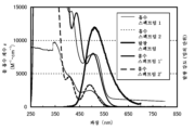
도 1a 및 1b는 실시예 1에 따른 흡수 스펙트럼 및 발광 스펙트럼을 나타내고,
도 2는 실시예의 발광 소자의 구조를 나타내고;
도 3은 실시예 2의 발광 소자의 전류 밀도 대 휘도 특성을 나타내고;
도 4는 실시예 2의 발광 소자의 전압 대 휘도 특성을 나타내고;
도 5는 실시예 2의 발광 소자의 휘도 대 전류 효율 특성을 나타내고;
도 6은 실시예 2의 발광 소자의 휘도 대 외부 양자 효율 특성을 나타내고;
도 7은 실시예 2의 발광 소자의 발광 스펙트럼을 나타내고;
도 8은 실시예 2의 발광 소자의 신뢰성 시험의 결과를 나타내고;
도 9는 실시예 3의 발광 소자의 전류 밀도 대 휘도 특성을 나타내고;
도 10은 실시예 3의 발광 소자의 전압 대 휘도 특성을 나타내고;
도 11은 실시예 3의 발광 소자의 휘도 대 전류 효율 특성을 나타내고;
도 12는 실시예 3의 발광 소자의 휘도 대 외부 양자 효율 특성을 나타내고;
도 13은 실시예 3의 발광 소자의 발광 스펙트럼을 나타내고;
도 14는 실시예 3의 발광 소자의 신뢰성 시험의 결과를 나타내고;
도 15는 본 발명의 실시양태의 발광 소자를 나타내고;
도 16은 실시예 1에 따른 흡수 스펙트럼 및 발광 스펙트럼을 나타내고;
도 17은 실시예 4에 따른 흡수 스펙트럼 및 발광 스펙트럼을 나타내고;
도 18은 실시예 5의 발광 소자의 전류 밀도 대 휘도 특성을 나타내고;
도 19는 실시예 5의 발광 소자의 전압 대 휘도 특성을 나타내고;
도 20은 실시예 5의 발광 소자의 휘도 대 전류 효율 특성을 나타내고;
도 21은 실시예 5의 발광 소자의 휘도 대 외부 양자 효율 특성을 나타내고;
도 22는 실시예 5의 발광 소자의 발광 스펙트럼을 나타내고;
도 23은 실시예 6에 따른 흡수 스펙트럼 및 발광 스펙트럼을 나타내고;
도 24는 실시예 7의 발광 소자의 전류 밀도 대 휘도 특성을 나타내고;
도 25는 실시예 7의 발광 소자의 전압 대 휘도 특성을 나타내고;
도 26은 실시예 7의 발광 소자의 휘도 대 전류 효율 특성을 나타내고;
도 27은 실시예 7의 발광 소자의 휘도 대 외부 양자 효율 특성을 나타내고;
도 28은 실시예 7의 발광 소자의 발광 스펙트럼을 나타내고;
도 29는 실시예 7의 발광 소자의 신뢰성 시험의 결과를 나타내고;
도 30은 실시예 8에 따른 흡수 스펙트럼 및 발광 스펙트럼을 나타내고;
도 31은 실시예 9의 발광 소자의 전류 밀도 대 휘도 특성을 나타내고;
도 32는 실시예 9의 발광 소자의 전압 대 휘도 특성을 나타내고;
도 33은 실시예 9의 발광 소자의 휘도 대 전류 효율 특성을 나타내고;
도 34는 실시예 9의 발광 소자의 휘도 대 외부 양자 효율 특성을 나타내고;
도 35는 실시예 9의 발광 소자의 발광 스펙트럼을 나타내고;
도 36은 실시예 9의 발광 소자의 신뢰성 시험의 결과를 나타내고;
도 37은 실시예 10에 따른 흡수 스펙트럼 및 발광 스펙트럼을 나타내고;
도 38은 실시예 11의 발광 소자의 전류 밀도 대 휘도 특성을 나타내고;
도 39는 실시예 11의 발광 소자의 전압 대 휘도 특성을 나타내고;
도 40은 실시예 11의 발광 소자의 휘도 대 전류 효율 특성을 나타내고;
도 41은 실시예 11의 발광 소자의 휘도 대 외부 양자 효율 특성을 나타내고;
도 42는 실시예 11의 발광 소자의 발광 스펙트럼을 나타내고;
도 43은 실시예 12에 따른 흡수 스펙트럼 및 발광 스펙트럼을 나타내고;
도 44는 실시예 13의 발광 소자의 전류 밀도 대 휘도 특성을 나타내고;
도 45는 실시예 13의 발광 소자의 전압 대 휘도 특성을 나타내고;
도 46은 실시예 13의 발광 소자의 휘도 대 전류 효율 특성을 나타내고;
도 47은 실시예 13의 발광 소자의 휘도 대 외부 양자 효율 특성을 나타내고;
도 48은 실시예 13의 발광 소자의 발광 스펙트럼을 나타내고;
도 49는 실시예 14에 따른 흡수 스펙트럼 및 발광 스펙트럼을 나타내고;
도 50은 실시예 15의 발광 소자의 전류 밀도 대 휘도 특성을 나타내고;
도 51는 실시예 15의 발광 소자의 전압 대 휘도 특성을 나타내고;
도 52는 실시예 15의 발광 소자의 휘도 대 전류 효율 특성을 나타내고;
도 53은 실시예 15의 발광 소자의 휘도 대 외부 양자 효율 특성을 나타내고; 및
도 54는 실시예 15의 발광 소자의 발광 스펙트럼을 나타낸다.In the accompanying drawings,
1a and 1b show an absorption spectrum and an emission spectrum according to Example 1,
2 shows the structure of the light emitting element of the embodiment;
3 shows the current density versus luminance characteristics of the light emitting device of Example 2;
4 shows the voltage vs. luminance characteristics of the light emitting device of Example 2;
5 shows the luminance vs. current efficiency characteristics of the light emitting device of Example 2;
6 shows the luminance versus external quantum efficiency characteristics of the light emitting device of Example 2;
7 shows the emission spectrum of the light emitting element of Example 2;
8 shows the results of a reliability test of the light emitting device of Example 2;
9 shows current density versus luminance characteristics of the light emitting device of Example 3;
10 shows voltage vs. luminance characteristics of the light emitting device of Example 3;
11 shows the luminance vs. current efficiency characteristics of the light emitting device of Example 3;
12 shows the luminance versus external quantum efficiency characteristics of the light emitting device of Example 3;
13 shows the emission spectrum of the light emitting element of Example 3;
14 shows the results of a reliability test of the light emitting device of Example 3;
15 shows a light emitting device of an embodiment of the present invention;
16 shows an absorption spectrum and an emission spectrum according to Example 1;
17 shows an absorption spectrum and an emission spectrum according to Example 4;
18 shows current density versus luminance characteristics of the light emitting device of Example 5;
19 shows voltage vs. luminance characteristics of the light emitting device of Example 5;
20 shows the luminance vs. current efficiency characteristics of the light emitting device of Example 5;
21 shows the luminance versus external quantum efficiency characteristics of the light emitting device of Example 5;
22 shows the emission spectrum of the light emitting element of Example 5;
23 shows an absorption spectrum and an emission spectrum according to Example 6;
24 shows current density versus luminance characteristics of the light emitting device of Example 7;
25 shows voltage vs. luminance characteristics of the light emitting device of Example 7;
26 shows the luminance vs. current efficiency characteristics of the light emitting device of Example 7;
27 shows the luminance versus external quantum efficiency characteristics of the light emitting device of Example 7;
28 shows the emission spectrum of the light emitting element of Example 7;
29 shows the results of the reliability test of the light emitting device of Example 7;
30 shows an absorption spectrum and an emission spectrum according to Example 8;
31 shows current density versus luminance characteristics of the light emitting device of Example 9;
32 shows voltage vs. luminance characteristics of the light emitting device of Example 9;
33 shows the luminance vs. current efficiency characteristics of the light emitting device of Example 9;
34 shows the luminance versus external quantum efficiency characteristics of the light emitting device of Example 9;
35 shows the emission spectrum of the light emitting element of Example 9;
36 shows the results of a reliability test of the light emitting device of Example 9;
37 shows an absorption spectrum and an emission spectrum according to Example 10;
38 shows current density versus luminance characteristics of the light emitting device of Example 11;
39 shows voltage vs. luminance characteristics of the light emitting device of Example 11;
40 shows the luminance vs. current efficiency characteristics of the light emitting device of Example 11;
41 shows the luminance versus external quantum efficiency characteristics of the light emitting device of Example 11;
42 shows the emission spectrum of the light emitting element of Example 11;
43 shows an absorption spectrum and an emission spectrum according to Example 12;
44 shows current density versus luminance characteristics of the light emitting device of Example 13;
45 shows the voltage vs. luminance characteristics of the light emitting element of Example 13;
46 shows the luminance vs. current efficiency characteristics of the light emitting device of Example 13;
47 shows the luminance versus external quantum efficiency characteristics of the light emitting device of Example 13;
48 shows the emission spectrum of the light emitting element of Example 13;
49 shows an absorption spectrum and an emission spectrum according to Example 14;
50 shows current density versus luminance characteristics of the light emitting device of Example 15;
51 shows voltage vs. luminance characteristics of the light emitting device of Example 15;
52 shows the luminance vs. current efficiency characteristics of the light emitting device of Example 15;
53 shows the luminance versus external quantum efficiency characteristics of the light emitting device of Example 15; and
54 shows the emission spectrum of the light emitting element of Example 15.
실시양태는 도면을 참조하여 기술될 것이다. 본 발명은 이하의 설명에 제한되지 않고, 본 발명의 취지 및 범위에서 벗어나지 않고 다양한 변경 및 수정이 만들어질 수 있음은 통상의 기술자에게 쉽게 이해될 것임을 유의한다. 따라서, 본 발명은 이하의 실시양태에서의 설명으로 제한되는 것으로 이해되어서는 안 된다. 이하 기재된 본 발명의 구조에서 동일한 부분 또는 유사한 기능을 가진 부분은 다른 도면에서 동일한 참조 번호로 나타내고, 이러한 부분의 설명은 반복되지 않음을 유의한다.Embodiments will be described with reference to the drawings. Note that the present invention is not limited to the following description, and it will be readily understood by those skilled in the art that various changes and modifications can be made without departing from the spirit and scope of the present invention. Accordingly, the present invention should not be construed as being limited to the description in the following embodiments. It should be noted that the same parts or parts having similar functions in the structure of the present invention described below are indicated by the same reference numerals in different drawings, and the description of these parts is not repeated.
(실시양태 1)(Embodiment 1)
실시양태 1은 본 발명의 한 실시양태의 발광 소자를 나타낸다.
본 실시양태의 발광 소자는 발광 물질인 게스트 재료와 게스트 재료가 분산되어 있는 호스트 재료를 포함하는 발광층을 포함한다. 게스트 재료는 인광 화합물을 사용한다. 호스트 재료는 1 종 이상의 유기 화합물을 사용할 수 있다.The light emitting device of this embodiment includes a light emitting layer including a guest material that is a light emitting material and a host material in which the guest material is dispersed. A phosphorescent compound is used as the guest material. One or more types of organic compounds can be used as the host material.
게스트 재료가 호스트 재료에 분산되어 있는 구조는 발광층의 결정화를 방지할 수 있다. 또한, 게스트 재료의 고농도에 의해 농도 켄칭을 억제하는 것이 가능하고, 따라서 발광 소자는 보다 높은 발광 효율을 가질 수 있다.The structure in which the guest material is dispersed in the host material can prevent crystallization of the light emitting layer. In addition, it is possible to suppress concentration quenching by the high concentration of the guest material, and therefore the light emitting element can have a higher luminous efficiency.
본 실시양태에 따라서, 호스트 재료로서 사용한 유기 화합물의 삼중항 여기 에너지의 준위(T1 준위)가 게스트 재료의 것보다 높은 것이 바람직하다. 이는 호스트 재료의 T1 준위가 게스트 재료의 것보다 낮을 때, 발광에 기여하는, 게스트 재료의 삼중항 여기 에너지가 호스트 재료에 의해 켄칭되어, 발광 효율이 감소하기 때문이다.According to this embodiment, it is preferable that the triplet excitation energy level (T 1 level) of the organic compound used as the host material is higher than that of the guest material. This is because, when the T 1 level of the host material is lower than that of the guest material, the triplet excitation energy of the guest material, which contributes to light emission, is quenched by the host material, reducing the luminous efficiency.
(발광의 기초 과정)(Basic course of luminescence)
먼저, 인광 화합물을 게스트 재료로서 사용하는 발광 소자에서 발광의 일반적인 기초 과정을 설명한다.First, a general basic process of light emission in a light emitting device using a phosphorescent compound as a guest material will be described.
(1) 게스트 분자에서 전자 및 정공이 재결합하고, 게스트 분자가 여기되는 경우 (직접 재결합 과정)(1) When electrons and holes recombine in guest molecules and the guest molecules are excited (direct recombination process)
(1-1) 게스트 분자의 여기 상태가 삼중항 여기 상태일 때, 게스트 분자는 인광을 발한다.(1-1) When the excited state of a guest molecule is a triplet excited state, the guest molecule emits phosphorescence.
(1-2) 게스트 분자의 여기 상태가 단일항 여기 상태일 때, 단일항 여기 상태의 게스트 분자는 삼중항 여기 상태로 항간 교차(intersystem crossing)하고, 인광을 발한다.(1-2) When the excited state of the guest molecules is a singlet excited state, the guest molecules in the singlet excited state intersystem cross into the triplet excited state and emit phosphorescence.
즉, (1)의 직접 재결합 과정에서, 게스트 분자의 항간 교차 효율 및 인광 양자 수율이 높은 한, 높은 발광 효율을 얻을 수 있다. 상술한 대로, 호스트 분자의 T1 준위가 게스트 분자의 것보다 높은 것이 바람직하다.That is, in the direct recombination process of (1), high luminous efficiency can be obtained as long as the interstitial crossover efficiency and phosphorescence quantum yield of the guest molecules are high. As described above, it is preferable that the T 1 level of the host molecule is higher than that of the guest molecule.
(2) 호스트 분자에서 전자 및 정공이 재결합하고, 호스트 분자가 여기 상태에 놓이는 경우 (에너지 이동 과정)(2) When electrons and holes recombine in the host molecule and the host molecule is in an excited state (energy transfer process)
(2-1) 호스트 물질의 여기 상태가 삼중항 여기 상태이고, 호스트 분자의 T1 준위가 게스트 분자의 것보다 높을 때, 호스트 분자로부터 게스트 분자로 여기 에너지가 이동하고, 따라서 게스트 분자는 삼중항 여기 상태에 놓인다. 삼중항 여기 상태에서 게스트 분자는 인광을 발한다. 이론상으로 에너지가 게스트 분자의 단일항 여기 에너지 상태(S1 준위)로 이동할 수 있음을 유의한다: 그러나 많은 경우 게스트 분자의 S1 준위는 호스트 분자의 T1 준위보다 높은 에너지를 가지기 때문에, 게스트 분자의 S1 준위로의 에너지 이동은 주된 에너지 이동 과정이 되기 어렵고; 따라서 이의 설명은 여기에서는 하지 않는다.(2-1) When the excited state of the host material is a triplet excited state and the T 1 level of the host molecule is higher than that of the guest molecule, the excitation energy is transferred from the host molecule to the guest molecule, and thus the guest molecule is a triplet excited state. placed here In the triplet excited state, guest molecules phosphoresce. Note that in theory energy can move to the singlet excitation energy state (S 1 level) of the guest molecule: however, in many cases the S 1 level of the guest molecule has a higher energy than the T 1 level of the host molecule, so the guest molecule The energy transfer of to the S 1 level is difficult to be the main energy transfer process; Therefore, a description thereof is not made here.
(2-2) 호스트 분자의 여기 상태가 단일항 여기 상태이고, 호스트 분자의 S1 준위가 게스트 분자의 S1 준위 및 T1 준위보다 높을 때, 호스트 분자로부터 게스트 분자로 여기 에너지가 이동하고, 따라서 게스트 분자는 단일항 여기 상태 또는 삼중항 여기 상태에 놓인다. 삼중항 여기 상태의 게스트 분자는 인광을 발한다. 또한, 단일항 여기 상태의 게스트 분자는 삼중항 여기 상태로 항간 교차하고 인광을 발한다.(2-2) When the excited state of the host molecule is a singlet excited state and the S 1 level of the host molecule is higher than the S 1 level and the T 1 level of the guest molecule, the excitation energy moves from the host molecule to the guest molecule; Thus, the guest molecule is either in a singlet excited state or a triplet excited state. Guest molecules in the triplet excited state phosphoresce. In addition, guest molecules in a singlet excited state intersect in a triplet excited state and emit phosphorescence.
즉, (2)의 에너지 이동 과정에서, 호스트 분자의 삼중항 여기 에너지 및 단일항 여기 에너지 모두가 게스트 분자로 얼마나 효율적으로 이동할 수 있는지가 중요하다.That is, in the energy transfer process of (2), it is important how efficiently both the triplet excitation energy and the singlet excitation energy of the host molecule can be transferred to the guest molecule.
(에너지 이동 과정)(Energy transfer process)
이하 분자 간의 에너지 이동 과정을 자세히 설명한다.Hereinafter, the energy transfer process between molecules will be described in detail.
우선, 분자 간의 에너지 이동의 메커니즘로서, 이하 2 개의 메커니즘이 제안된다. 여기 에너지를 제공하는 분자는 호스트 분자로 지칭하고, 여기 에너지를 받아들이는 분자는 게스트 분자로 지칭한다.First of all, as a mechanism of energy transfer between molecules, the following two mechanisms are proposed. Molecules that donate excitation energy are referred to as host molecules, and molecules that accept excitation energy are referred to as guest molecules.
(포스터(Foerster) 메커니즘 (쌍극자-쌍극자 상호작용))(Foerster mechanism (dipole-dipole interaction))
포스터 메커니즘(또한 포스터 공명 에너지 이동으로 지칭함)에서 에너지 이동에, 직접적인 분자간의 접촉은 필요하지 않다. 호스트 분자 및 게스트 분자 간의 쌍극자 진동의 공명 현상을 통해, 에너지 이동이 일어난다. 쌍극자 진동의 공명 현상은 호스트 분자가 게스트 분자로 에너지를 제공하게 하고, 따라서 호스트 분자는 기저 상태로 이완되고, 게스트 분자는 여기 상태에 놓인다. 포스터 메커니즘의 속도 상수 k h *→ g 를 수식(1)에 나타낸다.For energy transfer in the Förster mechanism (also referred to as Förster resonance energy transfer), no direct intermolecular contact is required. Energy transfer occurs through resonance of dipole vibrations between host and guest molecules. The resonance phenomenon of the dipole oscillation causes the host molecule to provide energy to the guest molecule, so the host molecule is relaxed to the ground state and the guest molecule is placed in an excited state. The rate constant k h *→ g of the Förster mechanism is expressed in Equation (1).

수식 (1)에서, ν는 진동수를 나타내고, f' h (ν)는 호스트 분자의 정규화된 발광 스펙트럼 (단일항 여기 상태로부터의 에너지 이동의 형광 스펙트럼 및 삼중항 여기 상태로부터 에너지 이동의 인광 스펙트럼)을 나타내고, ε g (ν)는 게스트 분자의 몰 흡수 계수를 나타내고, N은 아보가드로 수를 나타내고, n은 매질의 굴절률을 나타내고, R은 호스트 분자와 게스트 분자 사이의 분자간 거리를 나타내고, τ는 측정된 여기 상태의 수명(형광 수명 또는 인광 수명)을 나타내고, c는 광속을 나타내고, φ는 발광 양자 수율(단일항 여기 상태로부터의 에너지 이동의 형광 양자 수율 및 삼중항 여기 상태로부터 에너지 이동의 인광 양자 수율)을 나타내고 및 K 2 는 호스트 분자와 게스트 분자 간의 전이 쌍극자 모멘트의 배향의 계수(0 내지 4)를 나타낸다. 무작위 배향에서 K 2 = 2/3임을 유의한다.In equation (1), ν represents the frequency, and f′ h (ν) is the normalized emission spectrum of the host molecule (fluorescence spectrum of energy transfer from singlet excited state and phosphorescence spectrum of energy transfer from triplet excited state) , ε g (ν) represents the molar absorption coefficient of the guest molecule, N represents the Avogadro number, n represents the refractive index of the medium, R represents the intermolecular distance between the host and guest molecules, and τ represents the measured represents the lifetime of the excited state (fluorescence lifetime or phosphorescence lifetime), c represents the luminous flux, φ is the luminescence quantum yield (fluorescence quantum yield of energy transfer from a singlet excited state and phosphorescence quantum yield of energy transfer from a triplet excited state) yield) and K 2 represents the orientation coefficient (0 to 4) of the transition dipole moment between the host molecule and the guest molecule. K 2 in random orientation = 2/3.
(덱스터(Dexter) 메커니즘 (전자 교환 상호작용))(Dexter mechanism (electron exchange interaction))
덱스터 메커니즘(또한 덱스터 전자 이동으로도 지칭함)에서, 호스트 분자 및 게스트 분자는 그들의 궤도가 중첩되는 접촉 유효 범위로 근접하고, 여기 상태의 호스트 분자 및 기저 상태의 게스트 분자는 그들의 전자를 교환하여, 에너지 이동이 일어난다. 덱스터 메커니즘의 속도 상수 k h *→ g 를 수식(2)에 나타낸다.In the Dexter mechanism (also referred to as Dexter electron transfer), a host molecule and a guest molecule are brought into proximity with a contact effective range where their orbitals overlap, and the host molecule in the excited state and the guest molecule in the ground state exchange their electrons, resulting in energy movement takes place The rate constant k h *→ g of the Dexter mechanism is expressed in Equation (2).

수식(2)에서, h는 플랑크 상수를 나타내고, K는 에너지 차원을 갖는 상수를 나타내고, ν는 진동수를 나타내고, f' h (ν)는 호스트 분자의 정규화된 발광 스펙트럼(단일항 여기 상태로부터의 에너지 이동의 형광 스펙트럼 및 삼중항 여기 상태로부터 에너지 이동의 인광 스펙트럼)을 나타내고, ε' g (ν)는 게스트 분자의 정규화된 흡수 스펙트럼을 나타내고, L은 실효 분자 반경(effective molecular radius)을 나타내고 및 R은 호스트 분자와 게스트 분자 사이의 분자간 거리를 나타낸다.In Equation (2), h denotes the Planck constant, K denotes a constant having an energy dimension, ν denotes a frequency, and f' h (ν) denotes the normalized emission spectrum of the host molecule (from a singlet excited state). fluorescence spectrum of the energy transfer and phosphorescence spectrum of the energy transfer from the triplet excited state), ε' g (ν) represents the normalized absorption spectrum of the guest molecule, L represents the effective molecular radius, and R represents the intermolecular distance between host and guest molecules.
이 때, 호스트 분자로부터 게스트 분자로의 에너지 이동 효율(에너지 이동 효율 Φ ET )은 수식 (3)으로 표시된다고 생각된다. 수식에서, k r 은 호스트 분자의 발광 과정 (단일항 여기 상태로부터의 에너지 이동의 형광 및 삼중항 여기 상태로부터 에너지 이동의 인광)의 속도 상수를 나타내고, k n 은 호스트 분자의 비발광 과정(열적 비활성화 또는 항간 교차)의 속도 상수를 나타내고 및 τ는 호스트 물질의 측정된 여기 상태의 수명을 나타낸다.At this time, it is considered that the energy transfer efficiency from the host molecule to the guest molecule (energy transfer efficiency Φ ET ) is expressed by Formula (3). In the formula, k r represents the rate constant of the luminescent process of the host molecule (fluorescence of energy transfer from a singlet excited state and phosphorescence of energy transfer from a triplet excited state), and k n represents the non-luminescent process of the host molecule (thermal denotes the rate constant of deactivation or intersystem crossing) and τ represents the lifetime of the measured excited state of the host material.

우선, 수식 (3)에 따라서, 에너지 이동 효율 ΦET를 증가시키기 위해, 에너지 이동의 속도 상수 k h *→ g 를 다른 경합하는 속도 상수 k r + k n (=1/τ)에 비해 더 증가시킬 수 있다. 그리고, 에너지 이동의 속도 상수 k h *→ g 를 증가시키기 위해, 수식 (1) 및 (2)에 기초하여, 포스터 메커니즘 및 덱스터 메커니즘에서, 호스트 분자의 발광 스펙트럼(단일항 여기 상태로부터의 에너지 이동의 형광 스펙트럼이 삼중항 여기 상태로부터의 에너지 이동의 인광 스펙트럼과 크게 중첩된다) 및 게스트 분자의 흡수 스펙트럼이 바람직하다.First, according to Equation (3), in order to increase the energy transfer efficiency Φ ET , the rate constant k h * → g of energy transfer is converted to another competing rate constant k r + k n (= 1/ τ ) can be further increased. And, in order to increase the rate constant k h *→ g of energy transfer, based on equations (1) and (2), in the Förster mechanism and the Dexter mechanism, the luminescence spectrum of the host molecule (energy transfer from the singlet excited state The fluorescence spectrum of a highly overlaps with the phosphorescence spectrum of the energy transfer from the triplet excited state) and the absorption spectrum of the guest molecule are preferred.
이 때, 본 발명의 한 실시양태는 한 쌍의 전극 사이에, 게스트 재료 및 호스트 재료를 포함하는 발광층을 포함하고, 호스트 재료의 발광 스펙트럼이 게스트 재료의 흡수 스펙트럼과 중첩되고, 호스트 재료의 여기 에너지가 게스트 재료의 여기 에너지로 전환됨에 의해 인광을 발하는 발광 소자이다.At this time, one embodiment of the present invention includes a light emitting layer including a guest material and a host material between a pair of electrodes, the emission spectrum of the host material overlaps the absorption spectrum of the guest material, and the excitation energy of the host material is a light emitting element that emits phosphorescence by being converted into excitation energy of a guest material.
본 발명의 한 실시양태에 따라서, 호스트 재료의 발광 스펙트럼과 게스트 재료의 흡수 스펙트럼 간의 중첩을 사용하여, 호스트 재료로부터 게스트 재료로 에너지가 원활하게 이동하여 에너지 이동 효율이 높다. 따라서, 본 발명의 한 실시양태에 따라서, 외부 양자 효율이 높은 발광 소자가 실현될 수 있다.According to one embodiment of the present invention, by using the overlap between the emission spectrum of the host material and the absorption spectrum of the guest material, energy is smoothly transferred from the host material to the guest material, resulting in high energy transfer efficiency. Thus, according to one embodiment of the present invention, a light emitting element with high external quantum efficiency can be realized.
상술한 에너지 이동 과정에 비추어, 호스트 분자의 여기 에너지가 게스트 분자로 이동하기 전에, 호스트 분자 자체가 여기 에너지를 광 또는 열로서 방출하여 비활성화될 때, 발광 효율은 감소하고, 수명은 단축된다. 그러나 본 발명의 한 실시양태에 따라서, 에너지가 원활하게 이동하여 여기 에너지의 비활성화가 억제될 수 있다. 따라서 수명이 긴 발광 소자가 실현될 수 있다.In view of the above-described energy transfer process, when the host molecule itself emits excitation energy as light or heat to be deactivated before the excitation energy of the host molecule is transferred to the guest molecule, the luminous efficiency is reduced and the lifetime is shortened. However, according to one embodiment of the present invention, energy can be smoothly transferred and deactivation of excitation energy can be suppressed. Therefore, a light emitting element with a long lifetime can be realized.
여기서, 본 발명자들은 호스트 분자의 발광 스펙트럼과 게스트 분자의 흡수 스펙트럼 간의 중첩을 고려할 때, 게스트 분자의 흡수 스펙트럼에서 가장 긴 파장 측의(가장 낮은 에너지 측의) 흡수대가 중요함을 고려하였다.Here, the present inventors considered that the absorption band on the longest wavelength side (lowest energy side) of the guest molecule's absorption spectrum is important when considering the overlap between the emission spectrum of the host molecule and the absorption spectrum of the guest molecule.
본 실시양태에 따라서, 게스트 재료로 인광 화합물을 사용하였다. 인광 화합물의 흡수 스펙트럼에서, 발광에 가장 크게 기여하는 것으로 여겨지는 흡수대는 단일항 기저 상태로부터 삼중항 여기 상태로의 직접 전이에 해당하는 흡수 파장 및 그 흡수 파장의 근방이며, 이는 가장 긴 파장 측의 위에 있다. 따라서, 호스트 재료의 발광 스펙트럼(형광 스펙트럼 및 인광 스펙트럼)이 인광 화합물의 흡수 스펙트럼에의 가장 긴 파장 측의 흡수대와 중첩되는 것이 바람직한 것으로 생각된다.According to this embodiment, a phosphorescent compound was used as the guest material. In the absorption spectrum of a phosphorescent compound, the absorption band considered to contribute most to luminescence is the absorption wavelength corresponding to the direct transition from the singlet ground state to the triplet excited state and the vicinity of the absorption wavelength, which is the longest wavelength side. It is on top. Therefore, it is considered desirable that the emission spectrum (fluorescence spectrum and phosphorescence spectrum) of the host material overlap with the absorption band on the longest wavelength side of the absorption spectrum of the phosphorescent compound.
예를 들면, 대부분의 유기금속 착물, 특히 발광 이리듐 착물은 가장 긴 파장 측의 흡수대로서 500 nm 내지 600 nm 부근의 넓은 흡수대를 가진다(사실상, 넓은 흡수대는 발광 파장에 따라서 보다 짧거나 또는 보다 긴 파장 측의 위에 있을 수 있다). 상기 흡수대는 주로 삼중항 MLCT(금속의 리간드로의 전하 이동) 전이에 기반한다. 흡수대는 또한 삼중항 π-π* 전이 및 단일항 MLCT 전이에 기반한 흡수를 포함하고, 상기 흡수는 서로 중첩되어 흡수 스펙트럼의 가장 긴 파장 측의 위에 넓은 흡수대를 형성함을 유의한다. 따라서, 상술된 바와 같이, 게스트 재료로 유기금속 착물(특히 이리듐 착물)을 사용할 때, 가장 긴 파장 측의 위의 넓은 흡수대가 호스트 재료의 발광 스펙트럼과 크게 중첩되는 것이 바람직하다.For example, most organometallic complexes, especially luminescent iridium complexes, have a broad absorption band around 500 nm to 600 nm as an absorption band on the longest wavelength side (actually, a broad absorption band has a shorter or longer wavelength depending on the emission wavelength). can be on the side). The absorption band is mainly based on the triplet MLCT (charge transfer from metal to ligand) transition. Note that absorption bands also include absorptions based on the triplet π-π * transition and the singlet MLCT transition, which overlap with each other to form a broad absorption band above the longest wavelength side of the absorption spectrum. Therefore, as described above, when using an organometallic complex (particularly an iridium complex) as the guest material, it is preferable that the broad absorption band above the longest wavelength side overlaps greatly with the emission spectrum of the host material.
따라서 본 발명의 다른 실시양태는 한 쌍의 전극 사이에, 게스트 재료 및 호스트 재료를 포함하는 발광층을 포함하고, 호스트 재료의 발광 스펙트럼이 게스트 재료의 흡수 스펙트럼의 가장 긴 파장 측의 흡수대와 중첩되고, 호스트 재료의 여기 에너지가 게스트 재료의 여기 에너지로 전환됨에 의해 인광을 발하는 발광 소자이다.Therefore, another embodiment of the present invention includes a light emitting layer including a guest material and a host material between a pair of electrodes, wherein the emission spectrum of the host material overlaps with the absorption band on the longest wavelength side of the absorption spectrum of the guest material, A light emitting element that emits phosphorescence by converting excitation energy of a host material into excitation energy of a guest material.
상기 발광 소자에서, 흡수대는 바람직하게는 삼중항 MLCT 전이에 기반한 흡수를 포함한다. 삼중항 MLCT 여기 상태는 게스트 재료인 인광 화합물의 가장 낮은 삼중항 여기 상태이고, 따라서 인광 화합물은 이로부터 인광을 발한다. 즉, 삼중항 MLCT 여기 상태로부터의 인광은 발광 이외의 비활성화 과정에 관련되지 않고, 따라서 상기 여기 상태의 존재율을 가능한 높게 만들어서 고 발광 효율을 얻을 수 있다고 생각된다. 상기 이유로, 삼중항 MLCT 전이에 기반한 흡수를 사용하여, 호스트 재료로부터 삼중항 MLCT 여기 상태로 에너지가 직접 이동하는, 많은 에너지 이동 과정이 바람직하다. 상기 발광 소자에서, 게스트 재료는 바람직하게는 유기금속 착물, 보다 바람직하게는 이리듐 착물이다.In the light emitting device, the absorption band preferably includes absorption based on the triplet MLCT transition. The triplet MLCT excited state is the lowest triplet excited state of the phosphorescent compound as a guest material, and therefore the phosphorescent compound emits phosphorescence from it. That is, phosphorescence from the triplet MLCT excited state is not related to a deactivation process other than light emission, and therefore it is considered that high luminous efficiency can be obtained by making the abundance of the excited state as high as possible. For the above reasons, many energy transfer processes are desirable, in which energy is directly transferred from the host material to the triplet MLCT excited state using absorption based on the triplet MLCT transition. In the light emitting device, the guest material is preferably an organometallic complex, more preferably an iridium complex.
본 발명자들은 호스트 분자가 삼중항 여기 상태에 있을 때(상기 (2-1))와 비교하여, 호스트 분자가 단일항 여기 상태일 때(상기 (2-2)), 에너지가 게스트 분자, 즉 인광 화합물로 거의 이동하지 않기 쉽고, 발광 효율은 감소하기 쉽다는 것을 발견하였다. 따라서 본 발명자들은 그 사실을 과제로서 주목하였다.Compared to when the host molecule is in a triplet excited state ((2-1)), the present inventors have found that when the host molecule is in a singlet excited state ((2-2) above), energy is transferred to the guest molecule, that is, phosphorescence. It has been found that it hardly migrates into the compound and the luminous efficiency tends to decrease. Therefore, the present inventors paid attention to that fact as a problem.
호스트 재료로 형광 화합물이 일반적으로 사용되나, 이의 형광 수명(τ)은 나노초의 단위로, 매우 짧다 (k r +k n 은 높다). 이는 단일항 여기 상태로부터 기저 상태(단일항)로의 전이가 허용된 전이이기 때문이다. 수식 (3)으로부터, 이는 에너지 이동 효율 Φ ET 에는 불리하다. 이를 고려하면, 일반적으로 단일항 여기 상태의 호스트 재료로부터 게스트 재료로의 에너지 이동은 거의 일어나기 어렵다.A fluorescent compound is generally used as a host material, but its fluorescence lifetime ( τ ) is very short, on the order of nanoseconds ( k r + k n is high). This is because the transition from the singlet excited state to the ground state (singlet) is an allowed transition. From Equation (3), this is detrimental to the energy transfer efficiency Φ ET . Considering this, energy transfer from a host material in a singlet excited state to a guest material rarely occurs in general.
그러나, 본 발명의 한 실시양태는 이러한, 단일항 여기 상태의 호스트 재료로부터 게스트 재료로의 에너지 이동 효율의 문제점을 극복할 수 있다. 즉, 본 발명의 한 실시양태에 따르면, 발광 소자는 한 쌍의 전극 사이에, 게스트 재료 및 호스트 재료를 포함하는 발광층을 포함하고, 호스트 재료의 형광 스펙트럼은 바람직하게는 게스트 재료의 흡수 스펙트럼의 가장 긴 파장 측의 흡수대와 중첩되고, 그 중첩을 사용하여 호스트 재료의 여기 에너지가 게스트 재료의 여기 에너지로 전환됨에 의해 인광을 발한다.However, one embodiment of the present invention can overcome this problem of energy transfer efficiency from a host material to a guest material in a singlet excited state. That is, according to one embodiment of the present invention, the light emitting element includes a light emitting layer including a guest material and a host material between a pair of electrodes, and the fluorescence spectrum of the host material is preferably the highest of the absorption spectrum of the guest material. It overlaps with the absorption band on the long wavelength side, and the excitation energy of the host material is converted to the excitation energy of the guest material using the overlap, thereby emitting phosphorescence.
즉, 본 발명의 한 실시양태에 따른 발광 소자에서, 호스트 재료의 형광 스펙트럼은 게스트 재료의 흡수 스펙트럼의 가장 긴 파장 측의 흡수대와 중첩되고, 그 중첩을 사용하여 호스트 재료의 여기 에너지가 게스트 재료의 여기 에너지로 전환됨에 의해 인광을 발한다. 이러한 구성은 단일항 여기 에너지의 비활성화를 억제할 수 있다. 따라서 본 발명의 한 실시양태를 응용하면, 소자의 효율 및 이의 수명에도 영향을 줄 수 있는, 호스트 재료의 단일항 여기 에너지의 비활성화를 억제할 수 있어서, 수명이 긴 발광 소자를 실현할 수 있다. 이 때, 호스트 재료의 여기 에너지가 충분히 인광 화합물로 이동하고, 단일항 여기 상태로부터의 형광은 실질적으로 관찰되지 않는 것이 바람직하다.That is, in the light emitting device according to one embodiment of the present invention, the fluorescence spectrum of the host material overlaps with the absorption band on the longest wavelength side of the absorption spectrum of the guest material, and the excitation energy of the host material is increased by using the overlap. It emits phosphorescence by being converted into excitation energy. This configuration can suppress deactivation of singlet excitation energy. Therefore, when one embodiment of the present invention is applied, it is possible to suppress the inactivation of the singlet excitation energy of the host material, which can affect the efficiency and lifespan of the device, so that a light emitting device with a long lifetime can be realized. At this time, it is preferable that the excitation energy of the host material is sufficiently transferred to the phosphorescent compound and fluorescence from a singlet excited state is substantially not observed.
호스트 재료의 발광 스펙트럼과 게스트 재료의 흡수 스펙트럼이 충분히 중첩되게 하기 위해, 발광 스펙트럼의 피크의 에너지 값과 흡수 스펙트럼의 가장 낮은 에너지 측의 흡수대의 피크의 에너지 값의 차이는 바람직하게는 0.3 eV 이하이다. 차이는 더 바람직하게는 0.2 eV 이하이며, 보다 더 바람직하게는 0.1 eV 이하이다.In order to sufficiently overlap the emission spectrum of the host material and the absorption spectrum of the guest material, the difference between the energy value of the peak of the emission spectrum and the energy value of the peak of the absorption band on the lowest energy side of the absorption spectrum is preferably 0.3 eV or less. . The difference is more preferably 0.2 eV or less, and even more preferably 0.1 eV or less.
또한 단일항 여기 상태의 호스트 재료로부터의 에너지 이동에서, 포스터 메커니즘이 중요하게 생각된다. 이를 고려하면, 수식 (1)로부터 게스트 재료의 가장 긴 파장 측의 흡수대의 몰 흡수 계수는 바람직하게는 2000 M-1·cm-1 이상이고, 보다 바람직하게는 5000 M-1·cm-1 이상이다.Also in energy transfer from a host material in a singlet excited state, the Förster mechanism is considered important. Considering this, the molar absorption coefficient of the absorption band on the longest wavelength side of the guest material from Equation (1) is preferably 2000 M -1 cm -1 or more, more preferably 5000 M -1 cm -1 or more. am.
본 실시양태는 다른 실시양태와 적당히 조합할 수 있음을 유의한다.Note that this embodiment can be suitably combined with other embodiments.
(실시양태 2)(Embodiment 2)
본 실시양태는 도 15를 참조하여 본 발명의 한 실시양태의 발광 소자를 나타낸다.This embodiment shows a light emitting element of one embodiment of the present invention with reference to FIG. 15 .
도 15의 (a)는 제1 전극(103)과 제2 전극(108) 사이에 EL층(102)을 포함하는 발광 소자를 나타낸다. 도 15의 (a)의 발광 소자는 제1 전극(103) 위에 순서대로 적층한, 정공 주입층(701), 정공 수송층(702), 발광층(703), 전자 수송층(704) 및 전자 주입층(705)과 그 위에 제공된 제2 전극(108)을 포함한다.15(a) shows a light emitting element including an
제1 전극(103)은 바람직하게는 높은 일 함수(구체적으로는, 4.0 eV 이상)를 가진, 금속, 합금, 전도성 화합물, 이들의 혼합물 등을 사용하여 제조된다. 구체적 예는 산화 인듐-산화 주석(ITO: 산화 인듐 주석), 규소 또는 산화 규소를 함유한 산화 인듐-산화 주석, 산화 인듐-산화 아연(산화 인듐 아연), 산화 텅스텐 및 산화 아연을 함유한 산화 인듐(IWZO) 등을 포함한다. 상기 전도성 금속 산화물의 필름은 보통 스퍼터링법에 의해 제조되지만, 졸-겔법 등을 응용하여 제조될 수도 있다. 예를 들면, 산화 인듐-산화 아연 필름은, 산화 아연을 산화 인듐에 1 중량% 내지 20 중량%로 첨가한 표적물을 사용하여 스퍼터링법에 의해 제조할 수 있다. 또한 IWZO 필름은, 산화 텅스텐을 산화 인듐에 0.5 중량% 내지 5 중량%로, 산화 아연을 산화 인듐에 0.1 중량% 내지 1 중량%로 첨가한 표적물을 사용해서 스퍼터링법에 의해 제조할 수 있다. 기타 예는 그래핀(graphene), 금, 백금, 니켈, 텅스텐, 크롬, 몰리브덴, 철, 코발트, 구리, 팔라듐, 금속 재료의 질화물(예를 들면, 질화 티탄) 등이 있다.The
EL층(102)에 포함되고, 제1 전극(103)에 접하여 제조되는 층이, 유기 화합물과 전자 수용체(수용체)를 혼합하여 제조되는 후술하는 복합 재료를 사용하여 제조될 때, 제1 전극(103)은 일 함수에 상관없이, 임의의 다양한 금속, 합금, 전기 전도성 화합물 및 이들의 혼합물 등을 사용하여 제조할 수 있고; 예를 들어 알루미늄, 은, 알루미늄을 함유하는 합금(예를 들면, Al-Si) 등도 또한 사용할 수 있다.When a layer included in the
제1 전극(103)은, 예를 들면 스퍼터링법이나 증착법(진공 증착법을 포함) 등에 의해 제조할 수 있다.The
제2 전극(108)은 바람직하게는 낮은 일 함수(바람직하게는 3.8 eV 이하)를 가진, 임의의 금속, 합금, 전기 전도성 화합물, 이들의 혼합물 등을 사용하여 제조한다. 구체적인 예는 주기율표의 1족 및 2족에 속하는 원소, 즉 알칼리 금속, 예컨대 리튬 및 세슘, 알칼리 토금속, 예컨대 칼슘 및 스트론튬, 마그네슘, 이들의 합금(예를 들면, Mg-Ag 및 Al-Li), 희토류 금속, 예컨대 유로퓸 및 이테르븀, 이들의 합금, 알루미늄, 은 등을 포함한다.The
EL층(102)에 포함되고, 제2 전극(108)에 접하여 제조되는 층이, 유기 화합물과 전자 공여체(공여체)를 혼합해서 제조되는 후술하는 복합 재료를 사용하여 제조될 때, 제2 전극(108)은 일 함수에 상관없이, 임의의 다양한 전도성 재료, 예컨대 Al, Ag, ITO, 규소 또는 산화 규소를 함유한 산화 인듐-산화 주석을 사용하여 제조할 수 있다.When a layer included in the
제2 전극(108)을 제조할 때, 진공 증착법이나 스퍼터링법을 사용할 수 있음을 유의한다. 은 페이스트 등을 사용할 경우에는 코팅법, 잉크젯법 등을 사용할 수 있다.Note that when manufacturing the
EL층(102)은 적어도 발광층(703)을 포함한다. EL층(102)의 일부로는 공지된 물질을 사용할 수 있고, 저분자 화합물 또는 고분자 화합물의 어느 하나를 사용할 수 있다. EL층(102)을 제조하는 물질은 유기 화합물을 포함할 수 있거나 무기 화합물을 일부로서 포함할 수 있음을 유의한다.The
또한, 도 15의 (a)에 나타낸 바와 같이, EL층(102)은 발광층(703) 뿐만 아니라 이하 층들: 높은 정공 주입성을 가진 물질을 포함하는 정공 주입층(701), 높은 정공 수송성을 가진 물질을 포함하는 정공 수송층(702), 높은 전자 수송성을 가진 물질을 포함하는 전자 수송층(704), 높은 전자 주입성을 가진 물질을 포함하는 전자 주입층(705) 등의 적합한 조합을 포함한다.In addition, as shown in (a) of FIG. 15, the
정공 주입층(701)은 높은 정공 주입성을 가진 물질을 포함하는 층이다. 높은 정공 주입성을 가진 물질의 예는 금속 산화물, 예컨대 몰리브덴 산화물, 티탄 산화물, 바나듐 산화물, 레늄 산화물, 루테늄 산화물, 크롬 산화물, 지르코늄 산화물, 하프늄 산화물, 탄탈룸 산화물, 은 산화물, 텅스텐 산화물 및 망간 산화물을 포함한다. 다르게는, 프탈로시아닌계 화합물, 예컨대 프탈로시아닌(약칭: H2Pc), 구리(II) 프탈로시아닌(약칭: CuPc)를 사용할 수 있다.The
다른 예는 저분자 유기 화합물인 방향족 아민 화합물 등, 예컨대 4,4',4"-트리스(N,N-디페닐아미노)트리페닐아민(약칭: TDATA), 4,4',4"-트리스[N-(3-메틸페닐)-N-페닐아미노]트리페닐아민(약칭: MTDATA), 4,4'-비스[N-(4-디페닐아미노페닐)-N-페닐아미노]비페닐(약칭: DPAB), 4,4'-비스(N-{4-[N'-(3-메틸페닐)-N'-페닐아미노]페닐}-N-페닐아미노)비페닐(약칭: DNTPD), 1,3,5-트리스[N-(4-디페닐아미노페닐)-N-페닐아미노]벤젠(약칭: DPA3B), 3-[N-(9-페닐카르바졸-3-일)-N-페닐아미노]-9-페닐카르바졸(약칭: PCzPCA1), 3,6-비스[N-(9-페닐카르바졸-3-일)-N-페닐아미노]-9-페닐카르바졸(약칭: PCzPCA2) 및 3-[N-(1-나프틸)-N-(9-페닐카르바졸-3-일)아미노]-9-페닐카르바졸 (약칭: PCzPCN1)을 포함한다.Other examples include aromatic amine compounds that are low molecular weight organic compounds, such as 4,4',4"-tris( N , N -diphenylamino)triphenylamine (abbreviation: TDATA), 4,4',4"-tris[ N- (3-methylphenyl) -N -phenylamino]triphenylamine (abbreviation: MTDATA), 4,4'-bis[ N- (4-diphenylaminophenyl) -N -phenylamino]biphenyl (abbreviation: DPAB), 4,4'-bis( N- {4-[ N'- (3-methylphenyl) -N' -phenylamino]phenyl} -N -phenylamino)biphenyl (abbreviation: DNTPD), 1,3 ,5-tris[ N- (4-diphenylaminophenyl) -N -phenylamino]benzene (abbreviation: DPA3B), 3-[ N- (9-phenylcarbazol-3-yl) -N -phenylamino] -9-phenylcarbazole (abbreviation: PCzPCA1), 3,6-bis[ N- (9-phenylcarbazol-3-yl) -N -phenylamino]-9-phenylcarbazole (abbreviation: PCzPCA2) and 3 -[ N- (1-naphthyl) -N- (9-phenylcarbazol-3-yl)amino]-9-phenylcarbazole (abbreviation: PCzPCN1).
또 다른 예는 고분자 화합물(예를 들어, 올리고머, 덴드리머 및 폴리머), 예컨대 폴리(N-비닐카르바졸)(약칭: PVK), 폴리(4-비닐트리페닐아민)(약칭: PVTPA), 폴리[N-(4-{N'-[4-(4-디페닐아미노)페닐]페닐-N'-페닐아미노}페닐)메타크릴아미드](약칭: PTPDMA) 및 폴리[N,N'-비스(4-부틸페닐)-N,N'-비스(페닐)벤지딘](약칭: 폴리-TPD) 및 산을 첨가한 고분자 화합물, 예컨대 폴리(3,4-에틸렌디옥시티오펜)/폴리(스티렌술폰산)(PEDOT/PSS) 및 폴리아닐린/폴리(스티렌술폰산)(PAni/PSS)을 포함한다.Another example is a high molecular compound (eg, oligomer, dendrimer and polymer) such as poly( N -vinylcarbazole) (abbreviation: PVK), poly(4-vinyltriphenylamine) (abbreviation: PVTPA), poly[ N- (4-{ N'- [4-(4-diphenylamino)phenyl]phenyl- N'- phenylamino}phenyl)methacrylamide] (abbreviated as PTPDMA) and poly[ N , N' -bis( 4-butylphenyl) -N , N' -bis(phenyl)benzidine] (abbreviation: poly-TPD) and acid-added polymer compounds such as poly(3,4-ethylenedioxythiophene)/poly(styrenesulfonic acid) (PEDOT/PSS) and polyaniline/poly(styrenesulfonic acid) (PAni/PSS).
정공 주입층(701)은 유기 화합물과 전자 수용체(수용체)를 결합하여 제조되는 복합 재료를 사용하여 제조할 수 있다. 이러한 복합 재료는 전자 수용체에 의해 유기 화합물에 정공이 발생하기 때문에 높은 정공 주입성 및 정공 수송성을 갖는다. 상기 경우에, 유기 화합물은 바람직하게는 발생한 정공의 수송에 우수한 재료(높은 정공 수송성을 가진 물질)이다.The
복합 재료로 사용하는 유기 화합물의 예는 다양한 화합물, 예컨대 방향족 아민 화합물, 카르바졸 유도체, 방향족 탄화수소 및 고분자 화합물(예를 들어, 올리고머, 덴드리머 및 폴리머)이 될 수 있다. 복합 재료로 사용하는 유기 화합물은 바람직하게는 높은 정공 수송성을 갖는 유기 화합물이고, 구체적으로 바람직하게는 10-6 cm2/V·s 이상의 정공 이동도를 갖는 물질이다. 상기 물질 외에, 전자보다 정공을 더 수송하는 성질을 가진 임의의 물질을 사용할 수 있다. 이하에서는, 복합 재료로 사용할 수 있는 유기 화합물을 구체적으로 기술한다.Examples of the organic compound used as the composite material may be various compounds such as aromatic amine compounds, carbazole derivatives, aromatic hydrocarbons, and high molecular compounds (eg, oligomers, dendrimers, and polymers). The organic compound used as the composite material is preferably an organic compound having a high hole transport property, and specifically, preferably, a material having a hole mobility of 10 −6 cm 2 /V·s or more. In addition to the above materials, any material having a property of transporting more holes than electrons can be used. Hereinafter, organic compounds that can be used as composite materials are specifically described.
복합 재료로 사용할 수 있는 유기 화합물의 예는 방향족 아민 화합물, 예컨대 TDATA, MTDATA, DPAB, DNTPD, DPA3B, PCzPCA1, PCzPCA2, PCzPCN1, 4,4'-비스[N-(1-나프틸)-N-페닐아미노]비페닐(약칭: NPB 또는 α-NPD), N,N'-비스(3-메틸페닐)-N,N'-디페닐-[1,1'-비페닐]-4,4'디아민(약칭: TPD) 및 4-페닐-4'-(9-페닐플루오렌-9-일)트리페닐아민(약칭: BPAFLP) 및 카르바졸 유도체, 예컨대 4,4'-디(N-카르바졸릴)비페닐(약칭: CBP), 1,3,5-트리스[4-(N-카르바졸릴)페닐]벤젠(약칭: TCPB), 9-[4-(N-카르바졸릴)페닐]-10-페닐안트라센(약칭: CzPA), 9-페닐-3-[4-(10-페닐-9-안트릴)페닐]-9H-카르바졸(약칭: PCzPA) 및 1,4-비스[4-(N-카르바졸릴)페닐]-2,3,5,6-테트라페닐벤젠이다.Examples of organic compounds that can be used as composite materials include aromatic amine compounds such as TDATA, MTDATA, DPAB, DNTPD, DPA3B, PCzPCA1, PCzPCA2, PCzPCN1, 4,4'-bis[ N- (1-naphthyl) -N- Phenylamino]biphenyl (abbreviation: NPB or α-NPD), N , N' -bis(3-methylphenyl) -N , N'- diphenyl-[1,1'-biphenyl]-4,4'diamine (abbreviation: TPD) and 4-phenyl-4'-(9-phenylfluoren-9-yl)triphenylamine (abbreviation: BPAFLP) and carbazole derivatives such as 4,4'-di( N -carbazolyl ) Biphenyl (abbreviation: CBP), 1,3,5-tris[4-( N -carbazolyl)phenyl]benzene (abbreviation: TCPB), 9-[4-( N -carbazolyl)phenyl]- 10-phenylanthracene (abbreviation: CzPA), 9-phenyl-3-[4-(10-phenyl-9-anthryl)phenyl]-9 H -carbazole (abbreviation: PCzPA) and 1,4-bis[4 -(N-carbazolyl)phenyl]-2,3,5,6-tetraphenylbenzene.
다른 예는 방향족 탄화수소 화합물, 예컨대 2-tert-부틸-9,10-디(2-나프틸)안트라센(약칭: t-BuDNA), 2-tert-부틸-9,10-디(1-나프틸)안트라센, 9,10-비스(3,5-디페닐페닐)안트라센(약칭: DPPA), 2-tert-부틸-9,10-비스(4-페닐페닐)안트라센(약칭: t-BuDBA), 9,10-디(2-나프틸)안트라센(약칭: DNA), 9,10-디페닐안트라센(약칭: DPAnth), 2-tert-부틸안트라센(약칭:t-BuAnth), 9,10-비스(4-메틸-1-나프틸)안트라센(약칭: DMNA), 9,10-비스[2-(1-나프틸)페닐]-2-tert-부틸 안트라센, 9,10-비스[2-(1-나프틸)페닐]안트라센 및 2,3,6,7-테트라메틸-9,10-디(1-나프틸)안트라센이다.Other examples are aromatic hydrocarbon compounds such as 2- tert -butyl-9,10-di(2-naphthyl)anthracene (abbreviation: t-BuDNA), 2- tert -butyl-9,10-di(1-naphthyl) )Anthracene, 9,10-bis(3,5-diphenylphenyl)anthracene (abbreviation: DPPA), 2- tert -butyl-9,10-bis(4-phenylphenyl)anthracene (abbreviation: t-BuDBA), 9,10-di(2-naphthyl)anthracene (abbreviation: DNA), 9,10-diphenylanthracene (abbreviation: DPAnth), 2- tert -butylanthracene (abbreviation: t-BuAnth), 9,10-bis (4-methyl-1-naphthyl)anthracene (abbreviation: DMNA), 9,10-bis[2-(1-naphthyl)phenyl]-2- tert -butyl anthracene, 9,10-bis[2-( 1-naphthyl)phenyl]anthracene and 2,3,6,7-tetramethyl-9,10-di(1-naphthyl)anthracene.
또한 다른 예는 방향족 탄화수소 화합물, 예컨대 2,3,6,7-테트라메틸-9,10-디(2-나프틸)안트라센, 9,9'-비안트릴, 10,10'-디페닐-9,9'비안트릴, 10,10'-비스(2-페닐페닐)-9,9'-비안트릴, 10,10'-비스[(2,3,4,5,6-펜타페닐)페닐]-9,9'비안트릴, 안트라센, 테트라센, 루브렌, 페릴렌, 2,5,8,11-테트라(tert-부틸)페릴렌, 펜타센, 코로넨, 4,4'-비스(2,2-디페닐비닐)비페닐(약칭: DPVBi) 및 9,10-비스[4-(2,2-디페닐비닐)페닐]안트라센(약칭: DPVPA)이다.Still other examples are aromatic hydrocarbon compounds such as 2,3,6,7-tetramethyl-9,10-di(2-naphthyl)anthracene, 9,9′-bianthryl, 10,10′-diphenyl-9 ,9'Bianthryl, 10,10'-bis(2-phenylphenyl)-9,9'-bianthryl, 10,10'-bis[(2,3,4,5,6-pentaphenyl)phenyl] -9,9' bianthryl, anthracene, tetracene, rubrene, perylene, 2,5,8,11-tetra( tert -butyl)perylene, pentacene, coronene, 4,4'-bis(2 ,2-diphenylvinyl)biphenyl (abbreviation: DPVBi) and 9,10-bis[4-(2,2-diphenylvinyl)phenyl]anthracene (abbreviation: DPVPA).
또한 전자 수용체의 예는 유기 화합물, 예컨대 7,7,8,8-테트라시아노-2,3,5,6-테트라플루오로퀴노디메탄(약칭: F4-TCNQ) 및 클로라닐, 전이 금속 산화물, 주기율표에서 4족 내지 8족에 속하는 금속의 산화물 등이다. 구체적으로는 산화 바나듐, 산화 니오븀, 산화 탄탈룸, 산화 크롬, 산화 몰리브덴, 산화 텅스텐, 산화 망간 및 산화 레늄은 전자 수용성이 높기 때문에 바람직하다. 그 중에서도 산화 몰리브덴은 공기 중에서 안정하고, 흡습성이 낮고, 취급하기 쉽기 때문에 특히 바람직하다.Also examples of electron acceptors are organic compounds such as 7,7,8,8-tetracyano-2,3,5,6-tetrafluoroquinodimethane (abbreviation: F 4 -TCNQ) and chloranil, transition metals oxides, oxides of metals belonging to
상술한 전자 수용체 및 상술한 고분자 화합물, 예컨대 PVK, PVTPA, PTPDMA 또는 폴리-TPD를 사용하여 복합 재료를 제조할 수 있고, 정공 주입층(701)에 사용할 수 있다.A composite material can be prepared using the above-mentioned electron acceptor and the above-mentioned high molecular compound, such as PVK, PVTPA, PTPDMA or poly-TPD, and can be used for the
정공 수송층(702)은 정공 수송성이 높은 물질을 포함하는 층이다. 정공 수송성이 높은 물질의 예는 방향족 아민 화합물, 예컨대 NPB, TPD, BPAFLP, 4,4'-비스[N-(9,9-디메틸플루오렌-2-일)-N-페닐아미노]비페닐(약칭: DFLDPBi) 및 4,4'-비스[N-(스피로-9,9'-비플루오렌-2-일)-N-페닐아미노]비페닐(약칭: BSPB)이다. 여기에 언급한 물질은 주로 10-6 cm2/V·s 이상의 정공 이동도를 갖는 물질이다. 상기 물질 외에, 전자보다 정공을 더 수송하는 성질을 가진 임의의 물질을 사용할 수 있음을 유의한다. 정공 수송성이 높은 물질을 포함하는 층은 단일층으로 한정되지 않고, 임의의 상기 물질을 포함하는 2 이상의 층으로 적층한 것도 될 수 있음을 유의한다.The
다르게는, 정공 수송층(702)은 카르바졸 유도체, 예컨대 CBP, CzPA 또는 PCzPA, 또는 안트라센 유도체, 예컨대 t-BuDNA, DNA 또는 DPAnth를 사용하여 제조할 수 있다.Alternatively, the
또 다르게는, 정공 수송층(702)은 고분자 화합물, 예컨대 PVK, PVTPA, PTPDMA 또는 폴리-TPD를 사용하여 제조할 수 있다.Alternatively, the
발광층(703)은 발광 물질을 포함하는 층이다. 본 실시양태의 발광층(703)은 게스트 재료 및 호스트 재료를 포함한다. 호스트 재료로서 복수의 재료를 사용할 수 있다. 구체적으로는 실시양태 1을 참조할 수 있다.The
인광 화합물로서는, 유기 금속 착물이 바람직하고, 특히 이리듐 착물이 바람직하다. 상술한 포스터 메커니즘에 의한 에너지 이동을 고려하면, 인광 화합물의 가장 긴 파장 측의 흡수대의 몰 흡수 계수는 바람직하게는 2000 M-1·cm-1 이상이고, 보다 바람직하게는 5000 M-1·cm-1 이상이다. 이러한 높은 몰 흡수 계수를 갖는 화합물의 구체적 예는 비스(3,5-디메틸-2-페닐피라지나토)(디피발로일메타나토)이리듐(III)(약칭: [Ir(mppr-Me)2(dpm)]), (아세틸아세토나토)비스(4,6-디페닐피리미디나토)이리듐(III)(약칭: [Ir(dppm)2(acac)]), 비스(2,3,5-트리페닐피라지나토) (디피발로일메타나토)이리듐(III)(약칭: [Ir(tppr)2(dpm)]), (아세틸아세토나토)비스(6-메틸-4-페닐피리미디나토)이리듐(III)(약칭: [Ir(mppm)2(acac)]), (아세틸아세토나토)비스(6-tert-부틸-4-페닐피리미디나토)이리듐(III)(약칭: [Ir(tBuppm)2(acac)]) 등을 포함한다. 특히, [Ir(dppm)2(acac)]와 같이, 몰 흡수 계수가 5000 M-1·cm-1 이상인 재료는 외부 양자 효율이 약 30 %인 고효율 발광 소자를 제공할 수 있다.As the phosphorescent compound, an organometallic complex is preferable, and an iridium complex is particularly preferable. Considering the energy transfer by the Förster mechanism described above, the molar absorption coefficient of the absorption band on the longest wavelength side of the phosphorescent compound is preferably 2000 M -1 cm -1 or more, more preferably 5000 M -1 cm -1 or greater. A specific example of a compound having such a high molar absorption coefficient is bis(3,5-dimethyl-2-phenylpyrazinato)(dipivaloylmethanato)iridium(III) (abbreviated as [Ir(mppr-Me) 2 ( dpm)]), (acetylacetonato)bis(4,6-diphenylpyrimidinato)iridium(III) (abbreviation: [Ir(dppm) 2 (acac)]), bis(2,3,5-tri Phenylpyrazinato) (dipivaloylmethanato)iridium(III) (abbreviation: [Ir(tppr) 2 (dpm)]), (acetylacetonato)bis(6-methyl-4-phenylpyrimidinato)iridium (III) (abbreviation: [Ir(mppm) 2 (acac)]), (acetylacetonato)bis(6- tert -butyl-4-phenylpyrimidinato)iridium(III) (abbreviation: [Ir(tBuppm) 2 (acac)]) and the like. In particular, a material having a molar absorption coefficient of 5000 M −1 ·cm −1 or more, such as [Ir(dppm) 2 (acac)], can provide a highly efficient light emitting device with an external quantum efficiency of about 30%.
호스트 재료로 전자를 받아들이기 쉬운 화합물(대표적으로는, 헤테로시클릭 화합물)과 정공을 받아들이기 쉬운 화합물(대표적으로는, 방향족 아민 화합물 또는 카르바졸 화합물)의 혼합 재료를 사용하는 것이 바람직하다. 이러한 구성으로, 발광층은 정공 수송과 전자 수송 사이에 우수한 캐리어 밸런스를 갖출 수 있고, 이에 따라 발광 효율 및 수명을 향상시킬 수 있다. 호스트 재료의 구체적 예는 2-[3-(디벤조티오펜-4-일)페닐]디벤조[f,h]퀴녹살린(약칭: 2mDBTPDBq-II)과 4-페닐-4'-(9-페닐-9H-카르바졸-3-일)트리페닐아민(약칭: PCBA1BP)의 혼합 재료, 2mDBTPDBq-II와 4, 4'-디(1-나프틸)-4"-(9-페닐-9H-카르바졸-3-일)-트리페닐아민(약칭: PCBNBB)의 복합 재료, 2-[4-(3,6-디페닐-9H-카르바졸-9-일)페닐]디벤조[f,h]퀴녹살린(약칭: 2CzPDBq-III)과 PCBNBB의 복합 재료, 2-[4-(디벤조티오펜-4-일)페닐]-1-페닐-1H-벤조이미다졸(약칭: DBTBIm-II)과 4,4',4"-트리스[N-(1-나프틸)-N-페닐아미노]-트리페닐아민(약칭:1'-TNATA)의 복합 재료 등을 포함한다. 다르게는, 호스트 재료로 2mDBTPDBq-II와 다음의 것: 4,4'-비스[N-(1-나프틸)-N-페닐아미노]비페닐(약칭: NPB), 4-(1-나프틸)-4'-페닐트리페닐아민(약칭: αNBA1BP), 2,7-비스[N-(디페닐아미노페닐)-N-페닐아미노]-스피로-9,9'-비플루오렌(약칭: DPA2SF), 9-페닐-9H-3-(9-페닐-9H-카르바졸-3-일)카르바졸(약칭: PCCP) 및 1'-TNATA 중 임의의 것의 혼합 재료를 사용하는 것도 가능하다. 상기 물질에 제한되지 않고, 임의의 다른 공지된 호스트 재료를 또한 사용할 수 있음을 유의한다.As the host material, it is preferable to use a mixed material of a compound that readily accepts electrons (typically, a heterocyclic compound) and a compound that easily accepts holes (typically, an aromatic amine compound or a carbazole compound). With this configuration, the light emitting layer can have an excellent carrier balance between hole transport and electron transport, thereby improving light emitting efficiency and lifetime. Specific examples of the host material are 2-[3-(dibenzothiophen-4-yl)phenyl]dibenzo[ f , h ]quinoxaline (abbreviated name: 2mDBTPDBq-II) and 4-phenyl-4'-(9- Mixture of phenyl- 9H -carbazol-3-yl)triphenylamine (abbreviation: PCBA1BP), 2mDBTPDBq-II and 4,4'-di(1-naphthyl)-4"-(9-phenyl-9 H Composite material of -carbazol-3-yl)-triphenylamine (abbreviation: PCBNBB), 2-[4-(3,6-diphenyl- 9H -carbazol-9-yl)phenyl]dibenzo[ f , h ]quinoxaline (abbreviation: 2CzPDBq-III) and PCBNBB composite material, 2-[4-(dibenzothiophen-4-yl)phenyl]-1-phenyl- 1H -benzoimidazole (abbreviation: DBTBIm- II) and composite materials of 4,4',4"-tris[ N- (1-naphthyl) -N -phenylamino]-triphenylamine (abbreviation: 1'-TNATA), and the like. Alternatively, 2mDBTPDBq-II as a host material and the following: 4,4'-bis[ N- (1-naphthyl) -N -phenylamino]biphenyl (abbreviation: NPB), 4-(1-naphthyl) )-4'-phenyltriphenylamine (abbreviation: αNBA1BP), 2,7-bis[ N- (diphenylaminophenyl) -N -phenylamino]-spiro-9,9'-bifluorene (abbreviation: DPA2SF ), 9-phenyl- 9H- 3-(9-phenyl- 9H -carbazol-3-yl)carbazole (abbreviation: PCCP) and 1'-TNATA. . Note that, without being limited to the above materials, any other known host material may also be used.
또한, 복수의 층을 제공하고 이들의 발광 색상을 상이하게 함으로써, 발광 소자 전체로서 원하는 색상의 발광을 얻을 수 있다. 예를 들어, 발광층을 2 개 갖는 발광 소자에서 제1의 발광층의 발광 색상과 제2의 발광층의 발광 색상을 보색으로 하여, 발광 소자 전체로서 백색 발광하는 발광 소자를 제조할 수 있다. 단어 "보색"은 색상이 혼합될 때 무채색이 되는 색상 관계를 의미함을 유의한다. 즉, 발광 색상이 보색인 물질들로부터 얻어진 광을 혼합하여 백색 발광을 얻을 수 있다. 이는 발광층을 3 개 이상 갖는 발광 소자에도 적용할 수 있다.In addition, by providing a plurality of layers and differentiating their emission colors, it is possible to obtain light emission of a desired color as a light emitting element as a whole. For example, in a light emitting device having two light emitting layers, a light emitting device that emits white light as a whole can be manufactured by making the light emitting color of the first light emitting layer and the light emitting color of the second light emitting layer complementary colors. Note that the word “complementary color” refers to a color relationship that results in an achromatic color when colors are mixed. That is, white light emission can be obtained by mixing light obtained from materials having complementary colors of light emission. This can also be applied to a light emitting device having three or more light emitting layers.
전자 수송층(704)은 전자 수송성이 높은 물질을 포함하는 층이다. 전자 수송성이 높은 물질의 예는 금속 착물, 예컨대 Alq3, 트리스(4-메틸-8-퀴놀리놀레이토)알루미늄(약칭: Almq3), 비스(10-히드록시벤조[h]퀴놀리나토)베릴륨(약칭: BeBq2), BAlq, Zn(BOX)2 및 비스[2-(2-히드록시페닐)벤조티아졸라토]아연(약칭: Zn(BTZ)2)이다. 다른 예는 헤테로방향족 화합물, 예컨대 2-(4-비페닐릴)-5-(4-tert-부틸페닐)-1,3,4-옥사디아졸(약칭: PBD), 1,3-비스[5-(p-tert-부틸페닐)-1,3,4-옥사디아졸-2-일]벤젠(약칭: OXD-7), 3-(4-tert-부틸페닐)-4-페닐-5-(4-비페닐릴)-1,2,4-트리아졸(약칭: TAZ), 3-(4-tert-부틸페닐)-4-(4-에틸페닐)-5-(4-비페닐릴)-1,2,4-트리아졸(약칭: p-EtTAZ), 바소페난트롤린(약칭: BPhen), 바소큐프로인(약칭: BCP), 4,4'-비스(5-메틸벤족사졸-2-일)스틸벤(약칭: BzOs)이다. 또 다른 예는 고분자 화합물, 예컨대 폴리(2,5-피리딘-디일)(약칭: PPy), 폴리[(9,9-디헥실플루오렌-2,7-디일)-코-(피리딘-3,5-디일)](약칭: PF-Py) 및 폴리[(9,9-디옥틸플루오렌-2,7-디일)-코-(2,2-비피리딘-6,6'-디일)](약칭: PF-BPy)이다. 여기에 언급한 물질은 주로 10-6 cm2/V·s 이상의 전자 이동도를 갖는 물질이다. 상기 물질 외에, 전자보다 정공을 더 수송하는 성질을 가진 임의의 물질을 전자 수송층으로 사용할 수 있음을 유의한다.The
또한, 전자 수송층은 단일층으로 제한되지 않고, 임의의 상기 물질을 포함하는 2 이상의 층으로 적층한 것도 될 수 있다.Further, the electron transport layer is not limited to a single layer, and may be a laminate of two or more layers containing any of the above materials.
전자 주입층(705)은 전자 주입성이 높은 물질을 포함하는 층이다. 전자 주입층(705)에 사용할 수 있는 물질의 예는 알칼리 금속, 알칼리 토금속 및 이들의 화합물, 예컨대 리튬, 세슘, 칼슘, 플루오린화 리튬, 플루오린화 세슘, 플루오린화 칼슘 및 리튬 산화물, 희토류 금속 화합물, 예컨대 플루오린화 에르븀 및 상술한 전자 수송층(704)에 사용되는 물질이다.The
다르게는, 전자 주입층(705)에 유기 화합물과 전자 공여체(공여체)를 혼합하여 제조되는 복합 재료를 사용할 수 있다. 이러한 복합 재료는 전자 공여체에 의해 유기 화합물에 전자가 발생하기 때문에, 전자 주입성 및 전자 수송성이 높다. 여기서 유기 화합물은 발생한 전자의 수송에 우수한 재료인 것이 바람직하고, 구체적으로는, 상술한 전자 수송층(704)을 위한 임의의 물질 (예컨대, 금속 착물 및 헤테로방향족 화합물)을 사용할 수 있다. 전자 공여체로서는 유기 화합물에 대해 전자 공여성을 나타내는 물질을 사용할 수 있다. 전자 공여체의 바람직한 구체적인 예는 알칼리 금속, 알칼리 토금속 및 희토류 금속, 예컨대 리튬, 세슘, 마그네슘, 칼슘, 에르븀 및 이테르븀 및 알칼리 금속 산화물 및 알칼리 토금속 산화물, 예컨대 리튬 산화물, 칼슘 산화물 및 바륨 산화물이다. 또한, 산화 마그네슘과 같은 루이스 염기 또는 테트라티아풀발렌(약칭: TTF)과 같은 유기 화합물도 사용할 수 있다.Alternatively, a composite material prepared by mixing an organic compound and an electron donor (donor) may be used for the
상술한 정공 주입층(701), 정공 수송층(702), 발광층(703), 전자 수송층(704) 및 전자 주입층(705)은 각각 증착법(진공 증착법을 포함한다), 잉크젯법 또는 코팅법 등의 방법으로 제조할 수 있음을 유의한다.The
복수의 EL층은 도 15의 (b)에 나타낸 바와 같이, 제1 전극(103)과 제2 전극(108) 사이에 적층될 수 있다. 이 경우, 적층된 제1 EL층(800)과 제2 EL층(801) 사이에 전하 발생층(803)을 제공하는 것이 바람직하다. 전하 발생층(803)은 상술한 복합 재료를 사용하여 제조할 수 있다. 또한, 전하 발생층(803)은 복합 재료를 포함하는 층과 다른 재료를 포함하는 층의 적층 구조일 수 있다. 이 경우, 다른 재료를 포함하는 층으로서는, 전자 공여 물질과 전자 수송성이 높은 물질을 포함하는 층, 투명 전도성 필름으로 제조되는 층 등을 사용할 수 있다. 이러한 구성을 갖는 발광 소자는 에너지의 이동 및 켄칭 문제가 일어나기 어렵고, 재료의 선택의 폭이 넓으므로, 높은 발광 효율 및 긴 수명을 모두 갖는 발광 소자를 용이하게 얻을 수 있다. 또한, 한 EL층에서는 인광 발광을 그리고 다른 EL층에서는 형광 발광을 제공하는 발광 소자도 쉽게 얻을 수 있다. 상기 구조는 상술한 EL층의 임의의 구조와 조합시킬 수 있다.A plurality of EL layers may be stacked between the
또한, EL층의 발광 색상을 상이하게 함으로써, 발광 소자 전체로서 원하는 색상의 발광을 얻을 수 있다. 예를 들면, EL층을 2 개 갖는 발광 소자에서 제1 및 제2 EL층의 발광 색상을 보색으로 하여, 발광 소자 전체로서 백색 발광하는 발광 소자를 제조할 수 있다. 또한, 이는 EL층을 3 개 이상 갖는 발광 소자에도 동일하게 적용된다.In addition, by making the emission color of the EL layer different, the light emitting element as a whole can emit light of a desired color. For example, in a light emitting device having two EL layers, a light emitting device that emits white light as a whole can be manufactured by making the light emitting colors of the first and second EL layers complementary colors. Also, this applies equally to a light emitting element having three or more EL layers.
도 15의 (c)에 나타낸 바와 같이, EL층(102)은 제1 전극(103)과 제2 전극(108) 사이에 정공 주입층(701), 정공 수송층(702), 발광층(703), 전자 수송층(704), 전자 주입 버퍼층(706), 전자 계전(relay)층(707) 및 제2 전극(108)에 접하는 복합 재료층(708)을 포함할 수 있다.As shown in (c) of FIG. 15, the
특히 스퍼터링법으로 제2 전극(108)을 제조할 때 EL층(102)이 받는 손상을 감소시킬 수 있으므로, 제2 전극(108)에 접하는 복합 재료층(708)을 제공하는 것이 바람직하다. 복합 재료층(708)은 정공 수송성이 높은 유기 화합물에 수용체 물질을 함유시킨, 상술한 복합 재료를 사용하여 제조할 수 있다.In particular, since damage to the
또한, 전자 주입 버퍼층(706)을 제공함으로써, 복합 재료층(708)과 전자 수송층(704) 사이의 주입 장벽을 감소시킬 수 있고, 따라서 복합 재료층(708)에 발생한 전자를 전자 수송층(704)에 용이하게 주입할 수 있다.In addition, by providing the electron
전자 주입 버퍼층(706)은 전자 주입성이 높은 물질, 예컨대 알칼리 금속, 알칼리 토금속, 희토류 금속, 상기 금속의 화합물(예를 들어, 알칼리 금속 화합물 (산화 리튬 등의 산화물, 할로겐화물 및 탄산 리튬 또는 탄산 세슘 등의 탄산염을 포함), 알칼리 토금속 화합물(산화물, 할로겐화물 및 탄산염을 포함) 또는 희토류 금속 화합물(산화물, 할로겐화물 및 탄산염을 포함))을 사용하여 제조할 수 있다.The electron
또한, 전자 주입 버퍼층(706)이 전자 수송성이 높은 물질과 공여체 물질을 함유하는 경우에는, 전자 수송성이 높은 물질에 대한 공여체 물질의 질량비가 0.001:1 내지 0.1:1의 범위에 있도록 공여체 물질을 첨가하는 것이 바람직하다. 공여체 물질로서, 알칼리 금속, 알칼리 토금속, 희토류 금속, 상기 금속의 화합물(예를 들어, 알칼리 금속 화합물(산화 리튬 등의 산화물, 할로겐화물 및 탄산 리튬 또는 탄산 세슘 등의 탄산염을 포함), 알칼리 토금속 화합물(산화물, 할로겐화물 및 탄산염을 포함) 및 희토류 금속 화합물(산화물, 할로겐화물 및 탄산염을 포함)) 뿐 아니라 유기 화합물, 예컨대 테트라티아나프타센(약칭: TTN), 니켈로센 또는 데카메틸니켈로센이 사용될 수 있음을 유의한다. 전자 수송성이 높은 물질로서, 상기 기재한 전자 수송층(704)의 재료와 유사한 재료도 사용될 수 있음을 유의한다.In addition, when the electron
또한, 전자 주입 버퍼층(706)과 복합 재료층(708) 사이에 전자 계전층(707)을 형성하는 것이 바람직하다. 전자 계전층(707)은 반드시 제공할 필요는 없으나, 전자 수송성이 높은 전자 계전층(707)을 제공함으로써 전자 주입 버퍼층(706)에 전자를 신속하게 수송할 수 있다.In addition, it is preferable to form an
복합 재료층(708)과 전자 주입 버퍼층(706) 사이에 전자 계전층(707)이 끼워져 있는 구조에서, 복합 재료층(708)에 포함되는 수용체 물질과 전자 주입 버퍼층(706)에 포함되는 공여체 물질은 서로 상호작용하기 어렵고, 따라서 그들의 기능을 서로 저해하기 어렵다. 따라서, 구동 전압의 상승을 방지할 수 있다.In a structure in which the
전자 계전층(707)은 전자 수송성이 높은 물질을 포함하고, 전자 수송성이 높은 물질의 LUMO 준위가, 복합 재료층(708)에 포함되는 수용체 물질의 LUMO 준위와 전자 수송층(704)에 포함되는 전자 수송성이 높은 물질의 LUMO 준위 사이에 위치하도록 제조된다. 전자 계전층(707)이 공여체 물질을 포함하는 경우에는, 또한 공여체 물질의 공여체 준위도 또한 복합 재료층(708)에 포함되는 수용체 물질의 LUMO 준위와 전자 수송층(704)에 포함되는 전자 수송성이 높은 물질의 LUMO 준위 사이에 위치하도록 조절된다. 구체적인 에너지 준위의 값으로서, 전자 계전층(707)에 포함되는 전자 수송성이 높은 물질의 LUMO 준위는 바람직하게는 -5.0 eV 이상이고, 보다 바람직하게는 -5.0 eV 이상 및 -3.0 eV 이하이다.The
전자 계전층(707)에 포함되는 전자 수송성이 높은 물질로서는 프탈로시아닌계 재료 또는 금속-산소 결합 및 방향족 리간드를 갖는 금속 착물을 사용하는 것이 바람직하다.It is preferable to use a phthalocyanine-based material or a metal complex having a metal-oxygen bond and an aromatic ligand as the material included in the
전자 계전층(707)에 포함되는 프타로시아닌계 재료로, 구체적으로는 CuPc, 프탈로시아닌 주석(II) 착물(SnPc), 프탈로시아닌 아연 착물(ZnPc), 코발트(II) 프탈로시아닌, β-형태(CoPc), 프탈로시아닌 철(FePc) 및 바나딜 2,9,16,23-테트라페녹시-29H,31H-프탈로시아닌(PhO-VOPc) 중 임의의 것을 사용하는 것이 바람직하다.Examples of phthalocyanine-based materials included in the
전자 계전층(707)에 포함되는, 금속-산소 결합과 방향족 리간드를 갖는 금속 착물로 금속-산소의 이중 결합을 갖는 금속 착물을 사용하는 것이 바람직하다. 금속-산소의 이중 결합은 수용체 성질(전자를 수용하기 쉬운 성질)을 갖고, 따라서 전자가 보다 용이하게 이동(공여되고 수용됨)할 수 있다. 또한, 금속-산소의 이중 결합을 갖는 금속 착물은 안정한 것으로 생각된다. 따라서, 금속-산소의 이중 결합을 갖는 금속 착물을 사용함으로써 발광 소자를 저전압에서 더 안정적으로 구동하는 것이 가능하게 된다.It is preferable to use a metal complex having a metal-oxygen double bond as a metal complex having a metal-oxygen bond and an aromatic ligand included in the
금속-산소 결합과 방향족 리간드를 갖는 금속 착물로서는 프탈로시아닌계 재료가 바람직하다. 구체적으로는, 바나딜 프탈로시아닌(VOPc), 프탈로시아닌 주석(IV) 산화물 착물(SnOPc) 및 프탈로시아닌 티타늄 산화물 착물(TiOPc) 중 임의의 것이, 분자 구조적으로 금속-산소의 이중 결합이 다른 분자에 대하여 작용하기 쉽고, 수용성이 높기 때문에 바람직하다.As the metal complex having a metal-oxygen bond and an aromatic ligand, a phthalocyanine-based material is preferable. Specifically, any of vanadyl phthalocyanine (VOPc), phthalocyanine tin (IV) oxide complex (SnOPc), and phthalocyanine titanium oxide complex (TiOPc) is molecularly structurally resistant to metal-oxygen double bonds acting on other molecules. It is easy and water-soluble, so it is preferable.
상술한 프탈로시아닌계 재료로 페녹시 기를 갖는 프탈로시아닌계 재료가 바람직하다. 구체적으로는, 페녹시 기를 갖는 프탈로시아닌 유도체, 예컨대 PhO-VOPc가 바람직하다. 페녹시 기를 갖는 프탈로시아닌 유도체는 용매에 가용성이고, 따라서, 발광 소자를 제조하는 중에 취급이 용이하다는 이점 및 필름 제조에 사용하는 장치의 유지 보수를 용이하게 하는 이점을 갖는다.As the phthalocyanine-based material described above, a phthalocyanine-based material having a phenoxy group is preferable. Specifically, phthalocyanine derivatives having a phenoxy group, such as PhO-VOPc, are preferred. A phthalocyanine derivative having a phenoxy group is soluble in a solvent, and thus has an advantage of easy handling during production of a light emitting device and an advantage of easy maintenance of an apparatus used for film production.
전자 계전층(707)은 또한 공여체 물질을 포함할 수 있다. 공여체 물질로, 알칼리 금속, 알칼리 토금속, 희토류 금속 및 상기 금속의 화합물(예를 들어, 알칼리 금속 화합물(산화 리튬 등의 산화물, 할로겐화물 및 탄산 리튬 또는 탄산 세슘 등의 탄산염을 포함), 알칼리 토금속 화합물(산화물, 할로겐화물 및 탄산염을 포함) 및 희토류 금속 화합물(산화물, 할로겐화물 및 탄산염을 포함)) 뿐 아니라 유기 화합물, 예컨대 테트라티아나프타센(약칭: TTN), 니켈로센 또는 데카메틸니켈로센을 사용할 수 있다. 전자 계전층(707)에 이러한 공여체 물질이 포함될 때, 전자가 용이하게 이동할 수 있고, 발광 소자를 저전압에서 구동할 수 있다.The
전자 계전층(707)에 공여체 물질이 포함되는 경우, 전자 수송성이 높은 물질로서 상기 주어진 재료 외에, 복합 재료층(708)에 포함되는 수용체 물질의 수용체 준위보다 높은 LUMO 준위를 갖는 물질을 사용할 수 있다. 구체적으로는, -5.0 eV 이상, 바람직하게는 -5.0 eV 이상 및 -3.0 eV 이하의 LUMO 준위를 갖는 물질을 사용하는 것이 바람직하다. 이러한 물질의 예로, 페릴렌 유도체, 질소-함유 축합 방향족 화합물 등을 들 수 있다. 질소-함유 축합 방향족 화합물은 그것의 높은 안정성에 의해 전자 계전층(707)에 사용하는데 바람직하다.When the donor material is included in the
페릴렌 유도체의 구체적 예는 3,4,9,10-페릴렌테트라카르복실산 이무수물(약칭: PTCDA), 3,4,9,10-페릴렌테트라카르복실산-비스-벤즈이미다졸(약칭: PTCBI), N,N'-디옥틸-3,4,9,10-페릴렌테트라카르복실산 디이미드(약칭: PTCDI-C8H), N,N'-디헥실-3,4,9,10-페릴렌테트라카르복실산 디이미드(약칭: Hex PTC) 등이다.Specific examples of the perylene derivative include 3,4,9,10-perylenetetracarboxylic dianhydride (abbreviation: PTCDA), 3,4,9,10-perylenetetracarboxylic acid-bis-benzimidazole ( Abbreviation: PTCBI), N , N' -dioctyl-3,4,9,10-perylenetetracarboxylic acid diimide (abbreviation: PTCDI-C8H), N , N' -dihexyl-3,4,9 , 10-perylene tetracarboxylic diimide (abbreviation: Hex PTC) and the like.
질소-함유 축합 방향족 화합물의 구체적 예는 피라지노[2,3-f][1,10]페난트롤린-2,3-디카르보니트릴(약칭: PPDN), 2,3,6,7,10,11-헥사시아노-1,4,5,8,9,12-헥사아자트리페닐렌(약칭: HAT(CN)6), 2,3-디페닐피리도[2,3-b]피라진(약칭: 2PYPR), 2,3-비스(4-플루오로페닐)피리도[2,3-b]피라진(약칭: F2PYPR) 등이다.Specific examples of nitrogen-containing condensed aromatic compounds include pyrazino[2,3- f ][1,10]phenanthroline-2,3-dicarbonitrile (abbreviation: PPDN), 2,3,6,7,10 ,11-hexacyano-1,4,5,8,9,12-hexaazatriphenylene (abbreviation: HAT(CN) 6 ), 2,3-diphenylpyrido[2,3- b ]pyrazine (abbreviation: 2PYPR), 2,3-bis (4-fluorophenyl) pyrido [2,3- b ] pyrazine (abbreviation: F2PYPR) and the like.
이외에도, 7,7,8,8-테트라시아노퀴노디메탄(약칭: TCNQ), 1,4,5,8-나프탈렌 테트라카르복실산 이무수물(약칭: NTCDA), 퍼플루오로펜타센, 구리 헥사데카플루오로프탈로시아닌(약칭: F16CuPc), N,N'-비스(2,2,3,3,4,4,5,5,6,6,7,7,8,8,8-펜타데카플루오로옥틸)-1,4,5,8-나프탈렌테트라카르복실산 디이미드(약칭: NTCDI-C8F), 3',4'-디부틸-5,5"-비스(디시아노메틸렌)-5,5"-디히드로-2,2':5',2"-테르티오펜(약칭: DCMT), 메타노플레렌(예를 들면, [6,6]-페닐 C61 부티르산 메틸 에스테르) 등을 사용하는 것이 가능하다.In addition, 7,7,8,8-tetracyanoquinodimethane (abbreviation: TCNQ), 1,4,5,8-naphthalene tetracarboxylic dianhydride (abbreviation: NTCDA), perfluoropentacene, copper Hexadecafluorophthalocyanine (abbreviation: F 16 CuPc), N,N'-bis(2,2,3,3,4,4,5,5,6,6,7,7,8,8,8- pentadecafluorooctyl)-1,4,5,8-naphthalenetetracarboxylic diimide (abbreviation: NTCDI-C8F), 3',4'-dibutyl-5,5"-bis(dicyanomethylene) -5,5"-dihydro-2,2':5',2"-terthiophene (abbreviation: DCMT), methanoplene (eg [6,6]-phenyl C 61 butyric acid methyl ester ), etc. can be used.
전자 계전층(707)에 공여체 물질이 포함되는 경우, 전자 수송성이 높은 물질과 공여체 물질과의 공-증착 등의 방법에 의해 전자 계전층(707)을 제조할 수 있다.When the donor material is included in the
정공 주입층(701), 정공 수송층(702), 발광층(703) 및 전자 수송층(704)은 각각 상술한 재료를 사용해서 제조할 수 있다.The
상술한 바와 같이, 본 실시양태의 EL층(102)을 제조할 수 있다.As described above, the
상술한 발광 소자에서, 제1 전극(103)과 제2 전극(108) 사이에 발생한 전위차에 의해 전류가 흐르고, EL층(102)에서 정공과 전자가 재결합함으로써 발광한다. 이어서, 상기 발광은, 제1 전극(103) 또는 제2 전극(108) 중 어느 하나 또는 양쪽을 통해서 외부로 추출된다. 따라서, 제1 전극(103) 또는 제2 전극(108) 중 어느 하나 또는 양쪽이 가시광에 대해 투광성을 갖는 전극이다.In the light emitting element described above, a current flows due to a potential difference generated between the
제1 전극(103)과 제2 전극(108) 사이에 제공되는 층의 구조는 상술한 구조에 제한되지 않음을 유의한다. 다르게는, 발광 영역과 금속이 근접함으로써 발생하는 켄칭을 방지하도록 제1 전극(103) 및 제2 전극(108)으로부터 떨어진 부위에 정공과 전자가 재결합하는 발광 영역을 제공하는 한, 상기 이외의 구조도 사용할 수 있다.Note that the structure of the layer provided between the
즉, 층의 적층 구조에 관하여는 특별히 제한되지 않는다. 전자 수송성이 높은 물질, 정공 수송성이 높은 물질, 전자 주입성이 높은 물질, 정공 주입성이 높은 물질, 이극성 물질(전자 수송성 및 정공 수송성이 높은 물질), 정공 차단 재료 등을 포함하는 층을 발광층과 자유자재로 조합할 수 있다.That is, there is no particular restriction on the laminated structure of the layers. A layer including a material having high electron transport properties, a material having high hole transport properties, a material having high electron injection properties, a material having high hole injection properties, a bipolar material (a material having high electron transport properties and hole transport properties), a hole blocking material, and the like is formed as a light emitting layer. and can be combined freely.
본 실시양태에서 기술한 발광 소자를 사용하여, 트랜지스터에 의해 발광 소자의 구동이 제어되는 패시브 매트릭스형의 발광 장치 또는 액티브 매트릭스형의 발광 장치를 제조할 수 있다. 또한, 발광 장치를 전자 장치, 조명 장치 등에 응용할 수 있다.Using the light emitting element described in this embodiment, a passive matrix type light emitting device or an active matrix type light emitting device in which driving of the light emitting element is controlled by a transistor can be manufactured. In addition, the light emitting device can be applied to electronic devices, lighting devices, and the like.
상기 기재한 방식으로, 본 발명의 한 실시양태의 발광 소자를 제조할 수 있다.In the manner described above, the light emitting element of one embodiment of the present invention can be produced.
본 실시양태는 다른 실시양태와 적당히 조합할 수 있음을 유의한다.Note that this embodiment can be suitably combined with other embodiments.
[실시예 1][Example 1]
실시예 1은 본 발명의 한 실시양태의 발광 소자에 포함될 수 있는 게스트 재료 및 호스트 재료에 대해, 도 1a 및 1b 및 도 16을 참조하여 나타낸다.Example 1 shows with reference to FIGS. 1A and 1B and FIG. 16 the guest material and the host material that can be included in the light emitting device of one embodiment of the present invention.
본 실시예에서 사용하는 게스트 재료는 (아세틸아세토나토)비스(4,6-디페닐피리미디나토)이리듐(III)(약칭: [Ir(dppm)2(acac)]), 비스(3,5-디메틸-2-페닐피라지나토)(디피발로일메타나토)이리듐(III)(약칭: [Ir(mppr-Me)2(dpm)]) 및 (아세틸아세토나토)비스(6-메틸-4-페닐피리미디나토)이리듐(III)(약칭: [Ir(mppm)2(acac)])의 3 종류이다. 본 실시예에서 사용하는 호스트 재료는 또한, 2-[3-(디벤조티오펜-4-일)페닐]디벤조[f,h]퀴녹살린(약칭: 2mDBTPDBq-II)과 4-페닐-4'-(9-페닐-9H-카르바졸-3-일)트리페닐아민(약칭: PCBA1BP)의 혼합 재료이다. 본 실시예에서 사용한 재료의 화학식을 이하 나타낸다.The guest materials used in this embodiment are (acetylacetonato)bis(4,6-diphenylpyrimidinato)iridium(III) (abbreviation: [Ir(dppm) 2 (acac)]), bis(3,5 -Dimethyl-2-phenylpyrazinato)(dipivaloylmethanato)iridium(III) (abbreviation: [Ir(mppr-Me) 2 (dpm)]) and (acetylacetonato)bis(6-methyl-4 -Phenylpyrimidinato) iridium (III) (abbreviation: [Ir(mppm) 2 (acac)]). The host material used in this example is 2-[3-(dibenzothiophen-4-yl)phenyl]dibenzo[ f , h ]quinoxaline (abbreviation: 2mDBTPDBq-II) and 4-phenyl-4 It is a mixed material of '-(9-phenyl- 9H -carbazol-3-yl)triphenylamine (abbreviation: PCBA1BP). Chemical formulas of the materials used in this Example are shown below.

(게스트 재료의 흡수 스펙트럼 및 호스트 재료의 발광 스펙트럼의 측정 결과)(Measurement results of absorption spectrum of guest material and emission spectrum of host material)
(흡수 스펙트럼)(absorption spectrum)
도 1a 및 도 16은 [Ir(dppm)2(acac)]의 디클로로메탄 용액 중 [Ir(dppm)2(acac)]의 자외선-가시광선 흡수 스펙트럼(이하, 흡수 스펙트럼으로 간략하게 지칭)을 흡수 스펙트럼 1로 나타낸다. 마찬가지로, 도 1a 및 도 16은 [Ir(mppr-Me)2(dpm)]의 디클로로메탄 용액 중 [Ir(mppr-Me)2(dpm)]의 흡수 스펙트럼을 흡수 스펙트럼 2로, [Ir(mppm)2(acac)]의 디클로로메탄 용액 중 [Ir(mppm)2(acac)]의 흡수 스펙트럼을 흡수 스펙트럼 3으로 나타낸다.1A and 16 show a UV-visible absorption spectrum (hereinafter referred to simply as an absorption spectrum) of [Ir(dppm) 2 (acac)] in a dichloromethane solution of [Ir(dppm) 2 (acac)]. It is represented by
각각의 흡수 스펙트럼의 측정은 자외선-가시광선 분광 광도계(자스코 코포레이션(JASCO Corporation)에서 제조, V550 형)를 사용하여, 디클로로메탄 용액을 석영 셀에 넣고, 실온에서 행하였다.The measurement of each absorption spectrum was carried out at room temperature using an ultraviolet-visible spectrophotometer (type V550 manufactured by JASCO Corporation) in which a dichloromethane solution was placed in a quartz cell.
(발광 스펙트럼)(emission spectrum)
도 1a 및 도 16은 또한 2mDBTPDBq-II와 PCBA1BP의 혼합 재료의 박막의 발광 스펙트럼을 나타낸다. 도 1a에서, 가로축은 파장(nm)을 나타내고, 세로축은 몰 흡수 계수 ε(M-1·cm-1) 및 발광 강도(임의 단위)를 나타낸다. 도 16에서, 가로축은 에너지(eV)를 나타내고, 세로축은 몰 흡수 계수 ε(M-1·cm-1) 및 발광 강도(임의 단위)를 나타낸다.1A and 16 also show the emission spectrum of the thin film of the mixed material of 2mDBTPDBq-II and PCBA1BP. In FIG. 1A , the abscissa axis represents the wavelength (nm), and the ordinate axis represents the molar absorption coefficient ε (M −1 ·cm −1 ) and luminescence intensity (arbitrary unit). In FIG. 16, the horizontal axis represents energy (eV), and the vertical axis represents the molar absorption coefficient ε (M -1 cm -1 ) and emission intensity (arbitrary unit).
도 1a 및 도 16은 흡수 스펙트럼 1 내지 3이 각각 발광 스펙트럼과 중첩됨을 나타낸다. 따라서, 본 실시예의 게스트 재료의 임의의 하나와 본 실시예의 호스트 재료를 함께 사용한 발광층을 포함하는 발광 소자는, 호스트 재료의 발광 스펙트럼과 게스트 재료의 흡수 스펙트럼의 중첩을 사용하여 에너지가 이동하기 때문에, 에너지 이동 효율이 높은 것임이 시사된다.1A and 16 show that
이 때, 도 1a 및 도 16에서, 흡수 스펙트럼의 가장 긴 파장 측의(가장 낮은 에너지 측의) 흡수대(발광에 강하게 기여하는 것으로 여겨지는 흡수대)의 피크와 발광 스펙트럼의 피크에 주목한다. 흡수 스펙트럼 1 내지 3의 피크 중, 발광 스펙트럼의 피크와 가장 가까운 위치에 흡수 스펙트럼 1의 피크가 있고, 발광 스펙트럼의 피크와 가장 먼 위치에 흡수 스펙트럼 3의 피크가 있다.At this time, in Fig. 1A and Fig. 16, attention is paid to the peak of the absorption band on the longest wavelength side (lowest energy side) of the absorption spectrum (the absorption band believed to contribute strongly to emission) and the peak of the emission spectrum. Among the peaks of
구체적으로는, 도 16에서 흡수 스펙트럼 1의 피크와 발광 스펙트럼의 피크와의 차이는 0.02 eV이며, 흡수 스펙트럼 2의 피크와 발광 스펙트럼의 피크와의 차이는 0.12 eV이며, 흡수 스펙트럼 3의 피크와 발광 스펙트럼의 피크와의 차이는 0.23 eV이다.Specifically, in FIG. 16, the difference between the peak of
다음으로, 도 1a에서 흡수 스펙트럼의 가장 긴 파장 측의(가장 낮은 에너지 측의) 흡수대의 피크에서의 몰 흡수 계수에 주목한다. 흡수 스펙트럼 1 내지 3 중, 흡수 스펙트럼 1의 몰 흡수 계수가 가장 크고, 흡수 스펙트럼 2의 몰 흡수 계수가 가장 작다.Next, attention is paid to the molar absorption coefficient at the peak of the absorption band on the longest wavelength side (lowest energy side) of the absorption spectrum in FIG. 1A. Among
즉, 흡수 스펙트럼 1 내지 3 중, 흡수 스펙트럼 1의 가장 긴 파장 측의(가장 낮은 에너지 측의) 흡수대의 피크가 발광 스펙트럼의 피크와 가장 가깝고, 피크의 몰 흡수 계수가 가장 크다.That is, among
상기로부터, 흡수 스펙트럼 1은 발광 스펙트럼과 특히 크게 중첩됨을 발견하였다. 따라서, 2mDBTPDBq-II와 PCBA1BP의 혼합 재료를 호스트 재료로 그리고 [Ir(dppm)2(acac)]를 게스트 재료로 포함하는 발광 소자는, 혼합 재료의 발광 스펙트럼과 [Ir(dppm)2(acac)]의 흡수 스펙트럼의 중첩을 사용하여 에너지가 이동하기 때문에, 에너지 이동 효율이 특히 높은 것임이 시사된다.From the above, it was found that the
(게스트 재료의 흡수 스펙트럼의 계산 결과)(Calculation result of absorption spectrum of guest material)
다음으로, 상기 측정에서 얻은, [Ir(dppm)2(acac)] 및 [Ir(mppr-Me)2(dpm)]의 흡수 스펙트럼(도 1a의 흡수 스펙트럼 1 및 2)을 계산을 통해 재현을 시도하였다.Next, the absorption spectra of [Ir(dppm) 2 (acac)] and [Ir(mppr-Me) 2 (dpm)] obtained from the above measurement (
[Ir(dppm)2(acac)] 및 [Ir(mppr-Me)2(dpm)]의 흡수 스펙트럼을 얻기 위해, 각 분자의 기저 상태에서의 가장 안정된 구조를 사용하여 여기 에너지 및 진동자 강도를 계산하였다. 산출한 진동자 강도를 기초로 흡수 스펙트럼을 얻었다. 구체적인 계산 방법을 이하 나타낸다.To obtain the absorption spectra of [Ir(dppm) 2 (acac)] and [Ir(mppr-Me) 2 (dpm)], the most stable structure in the ground state of each molecule is used to calculate the excitation energy and oscillator intensity. did An absorption spectrum was obtained based on the calculated vibrator intensity. A specific calculation method is shown below.
밀도 범함수법(DFT)을 사용하여, [Ir(dppm)2(acac)] 및 [Ir(mppr-Me)2(dpm)]의 기저 상태의 가장 안정한 구조를 계산하였다. 다음으로, 시간 -의존 밀도 범함수법(TD-DFT)을 사용하여, [Ir(dppm)2(acac)] 및 [Ir(mppr-Me)2(dpm)]의 여기 에너지와 진동자 강도를 얻었고, 이 결과로부터 이들의 흡수 스펙트럼을 계산하였다. DFT에서 총 에너지는, 위치 에너지, 전자 간 정전기 에너지, 전자의 운동 에너지 및 전자 간 모든 복잡한 상호작용을 포함하는 교환-상관 에너지의 합으로 표시된다. 또한 DFT에서는, 교환-상관 상호작용을 전자 밀도로 표현된 하나의 전자 포텐셜의 함수(즉, 다른 함수의 함수)로 근사하여, 매우 정확한 계산이 가능하다. 이 때, 혼합 함수인 B3PW91을 사용하여 교환-상관 에너지에 관련된 각 매개변수의 가중값을 구체화하였다. 또한, 기저 함수로서, LanL2DZ를 Ir 원자에, 6-311(각 원자가 궤도에 세 개의 단축 함수를 사용한 삼중-갈라짐 원자가 기저계의 기저 함수)을 Ir 원자 이외의 원자에 적용하였다. 상기 기저 함수는, 예를 들어 수소 원자의 경우 1s 내지 3s의 궤도 그리고 탄소 원자의 경우 1s 내지 4s 궤도 및 2p 내지 4p의 궤도가 관련된다. 또한, 계산 정밀도 향상을 위해, 분극 기저계로서 수소 원자 및 수소 이외의 원자, 각각에 p함수 및 d함수를 첨가하였다.Density functional method (DFT) was used to calculate the most stable structures of the ground states of [Ir(dppm) 2 (acac)] and [Ir(mppr-Me) 2 (dpm)]. Next, the excitation energy and oscillator intensity of [Ir(dppm) 2 (acac)] and [Ir(mppr-Me) 2 (dpm)] were obtained using the time-dependent density functional method (TD-DFT), From these results, their absorption spectra were calculated. In DFT, total energy is expressed as the sum of potential energy, electrostatic energy between electrons, kinetic energy of electrons, and exchange-correlation energy including all complex interactions between electrons. Also, in DFT, the exchange-correlation interaction is approximated as a function of one electron potential expressed as an electron density (i.e., a function of another function), so that very accurate calculations are possible. At this time, the weighted value of each parameter related to the exchange-correlation energy was specified using the mixing function B3PW91. In addition, as a basis function, LanL2DZ was applied to Ir atoms and 6-311 (basis function of a triple-branched valence basis system using three shortening functions for each valence orbital) was applied to atoms other than Ir atoms. The basis function relates, for example, to 1s to 3s orbitals for hydrogen atoms and 1s to 4s orbitals and 2p to 4p orbitals for carbon atoms. In addition, in order to improve calculation accuracy, a p function and a d function are added to each of the hydrogen atom and the non-hydrogen atom as a polarization basis system.
양자 화학 계산 프로그램으로서 가우시안(Gaussian) 09를 사용하였음을 유의한다. 고성능 컴퓨터(SGI 일본, Ltd. 제조, 알틱스(Altix) 4700)를 사용하여 계산하였다.Note that Gaussian 09 was used as the quantum chemistry calculation program. It was calculated using a high-performance computer (Altix 4700, manufactured by SGI Japan, Ltd.).
도 1b는 계산으로 얻은 흡수 스펙트럼을 나타낸다. 비교로서 도 1b는 또한 상술한, 측정하여 얻은 흡수 스펙트럼을 나타낸다. 구체적으로는, 측정하여 얻은 [Ir(dppm)2(acac)]의 흡수 스펙트럼을 흡수 스펙트럼 1로 나타내고, 계산으로 얻은 흡수 스펙트럼을 흡수 스펙트럼 1'로 나타낸다. 또한, 측정하여 얻은 [Ir(mppr-Me)2(dpm)]의 흡수 스펙트럼을 흡수 스펙트럼 2로 나타내고, 계산으로 얻은 흡수 스펙트럼을 흡수 스펙트럼 2'로 나타낸다. 도 1b에서, 가로축은 파장(nm)을 나타내고, 세로축은 몰 흡수 계수 ε(M-1·cm-1) 및 발광 강도(임의 단위)를 나타낸다.Figure 1b shows the absorption spectrum obtained by calculation. As a comparison, Fig. 1b also shows the above-mentioned absorption spectrum obtained by the measurement. Specifically, the absorption spectrum of [Ir(dppm) 2 (acac)] obtained by measurement is indicated as
도 1b에 나타낸 바와 같이, 측정하여 얻은 흡수 스펙트럼 1 및 흡수 스펙트럼 2는 각각, 계산으로 얻은 흡수 스펙트럼 1' 및 흡수 스펙트럼 2'와 실질적으로 동일한 형상을 가진다. 특히, 흡수 스펙트럼 1 및 2의 이하의 2 개의 경향을 흡수 스펙트럼 1' 및 2'에서도 또한 볼 수 있다.As shown in Fig. 1B,
경향 1: 흡수 스펙트럼 2 (2')의 피크 파장보다, 흡수 스펙트럼 1 (1')의 피크 파장이 발광 스펙트럼의 피크 파장에 더 가깝다.Tendency 1: The peak wavelength of absorption spectrum 1 (1') is closer to the peak wavelength of the emission spectrum than the peak wavelength of absorption spectrum 2 (2').
경향 2: 흡수 스펙트럼의 가장 긴 파장 측의 흡수대의 피크 파장의 몰 흡수 계수는, 흡수 스펙트럼 1 (1') 쪽이 흡수 스펙트럼 2 (2')보다 크다.Tendency 2: The molar absorption coefficient at the peak wavelength of the absorption band on the longest wavelength side of the absorption spectrum is larger in the absorption spectrum 1 (1') than in the absorption spectrum 2 (2').
[실시예 2][Example 2]
실시예 2는 본 발명의 한 실시양태의 발광 소자를 도 2를 참조하여 나타낸다. 본 실시예에서 사용한 재료의 화학식을 이하 나타낸다. 앞선 실시예에서 사용한 재료의 화학식은 여기서는 생략함을 유의한다.Example 2 shows a light emitting device of one embodiment of the present invention with reference to FIG. 2 . Chemical formulas of the materials used in this Example are shown below. Note that the chemical formulas of the materials used in the previous examples are omitted here.

이하는 본 실시예의 발광 소자 1 내지 3의 제조 방법을 나타낸다.The manufacturing method of the
(발광 소자 1)(light emitting element 1)
우선, 유리 기판(1100) 위에 산화 규소를 포함하는 인듐 주석 산화물(ITSO)의 막을 스퍼터링법으로 제조하여, 애노드로서 기능하는 제1 전극(1101)을 제조하였다. 두께는 110 nm 이었고 전극 면적은 2 mm × 2 mm이었다.First, a
다음으로, 기판(1100) 위에 발광 소자를 제조하기 위한 전처리로서, 기판 표면을 물로 세척하고, 200 ℃로 1 시간 동안 소성(baking)하고, UV 오존 처리를 370 초간 행하였다.Next, as a pretreatment for manufacturing a light emitting device on the
그 후, 대략 10-4 Pa까지 감압한 진공 증착 장치에 기판(1100)을 옮기고, 진공 증착 장치의 가열실에서 170 ℃로 30 분간 진공 소성을 행한 후, 기판(1100)을 약 30 분간 냉각시켰다.Thereafter, the
다음으로, 제1 전극(1101)이 제공된 표면이 하측이 되도록 제1 전극(1101)이 제공된 기판(1100)을 진공 증착 장치 내의 기판 홀더에 고정하였다. 진공 증착 장치의 압력을 약 10-4 Pa까지 감소시켰다. 이어서, 제1 전극(1101) 위로 4-페닐-4'-(9-페닐플루오렌-9-일)트리페닐아민(약칭: BPAFLP)과 산화 몰리브덴(VI)을 공-증착하여, 정공 주입층(1111)을 제조하였다. 정공 주입층(1111)의 두께는 40 nm이었고, BPAFLP의 산화 몰리브덴에 대한 중량비는 4:2(=BPAFLP:산화 몰리브덴)로 조절하였다.Next, the
다음으로, 정공 주입층(1111) 위로 BPAFLP 막을 20 nm의 두께가 되도록 제조하여, 정공 수송층(1112)을 제조하였다.Next, a BPAFLP film was formed over the
또한, 2mDBTPDBq-II, PCBA1BP 및 [Ir(dppm)2(acac)]를 공-증착하여, 정공 수송층(1112) 위에 발광층(1113)을 제조하였다. 2mDBTPDBq-II의 PCBA1BP 및 [Ir(dppm)2(acac)]에 대한 중량비는 0.8:0.2:0.05(= 2mDBTPDBq-II:PCBA1BP: [Ir(dppm)2(acac)])로 조절하였다. 발광층(1113)의 두께는 40 nm이었다.In addition, 2mDBTPDBq-II, PCBA1BP, and [Ir(dppm) 2 (acac)] were co-deposited to prepare a
다음으로, 발광층(1113) 위로 2mDBTPDBq-II 막을 10 nm의 두께가 되도록 제조하여, 제1 전자 수송층(1114a)을 제조하였다.Next, a 2mDBTPDBq-II film was formed over the
다음으로, 제1 전자 수송층(1114a) 위로 바소페난트롤린(약칭: BPhen) 막을 20 nm의 두께가 되도록 제조하여, 제2 전자 수송층(1114b)을 제조하였다.Next, a vasophenanthroline (abbreviation: BPhen) film was formed to a thickness of 20 nm on the first
또한, 제2 전자 수송층(1114b) 위로 플루오린화 리튬(LiF) 막을 1 nm의 두께가 되도록 증착하여, 전자 주입층(1115)을 제조하였다.In addition, an
마지막으로, 알루미늄 막을 200 nm의 두께가 되도록 증착하여 캐소드로서 기능하는 제2 전극(1103)을 제조하였다. 따라서, 본 실시예의 발광 소자 1을 제조하였다.Finally, an aluminum film was deposited to a thickness of 200 nm to prepare a
(발광 소자 2)(light emitting element 2)
발광 소자 2의 발광층(1113)은 2mDBTPDBq-II, PCBA1BP 및 [Ir(mppr-Me)2(dpm)]을 공-증착하여 제조하였다. 2mDBTPDBq-II의 PCBA1BP 및 [Ir(mppr-Me)2(dpm)]에 대한 중량비는 0.8:0.2:0.05(= 2mDBTPDBq-II:PCBA1BP:[Ir(mppr-Me)2(dpm)])로 조절하였다. 발광층(1113)의 두께는 40 nm 이었다. 발광층(1113)이외의 층은 발광 소자 1과 동일한 방식으로 제조하였다.The
(발광 소자 3)(light emitting element 3)
발광 소자 3의 발광층(1113)은 2mDBTPDBq-II, PCBA1BP 및 [Ir(mppm)2(acac)]를 공-증착하여 제조하였다. 2mDBTPDBq-II의 PCBA1BP 및 [Ir(mppm)2(acac)]에 대한 중량비는 0.8:0.2:0.05(= 2mDBTPDBq-II:PCBA1BP:[Ir(mppm)2(acac)])로 조절하였다. 발광층(1113)의 두께는 40 nm 이었다. 발광층(1113) 이외의 층은 발광 소자 1과 동일한 방식으로 제조하였다.The
상기 증착 과정에서 증착은 모두 저항 가열법으로 수행하였음을 유의한다.Note that in the above deposition process, all depositions were performed by resistance heating.
이상에 의해 얻은 발광 소자 1 내지 3의 소자 구조를 표 1에 나타낸다.Table 1 shows the device structures of the light-emitting
전극No. 1
electrode
주입층hole
injection layer
수송층second electron
transport layer
전극2nd
electrode
20 nmBPAFLP
20 nm
40 nm2mDBTPDBq-II:PCBA1BP: [Ir(dppm) 2 (acac)] (=0.8:0.2:0.05)
40 nm
10 nm2mDBTPDBq-II
10 nm
20 nmBPhen
20 nm
1 nmLiF
1 nm
200 nmAl
200 nm
40 nm2mDBTPDBq-II:PCBA1BP:[Ir(mppr-Me) 2 (dpm)] (=0.8:0.2:0.05)
40 nm
10 nm2mDBTPDBq-II
10 nm
20 nmBPhen
20 nm
1 nmLiF
1 nm
200 nmAl
200 nm
40 nm2mDBTPDBq-II:PCBA1BP:[Ir(mppm) 2 (acac)] (=0.8:0.2:0.05)
40 nm
10 nm2mDBTPDBq-II
10 nm
20 nmBPhen
20 nm
1 nmLiF
1 nm
200 nmAl
200 nm
질소 분위기를 함유한 글로브 박스 안에서 상기 발광 소자가 공기에 노출되지 않도록 밀봉하였다. 이어서, 상기 발광 소자의 동작 특성을 측정하였다. 측정은 실온(25 ℃로 유지된 분위기)에서 행하였음을 유의한다.The light emitting device was sealed so as not to be exposed to air in a glove box containing a nitrogen atmosphere. Next, operating characteristics of the light emitting device were measured. Note that the measurement was conducted at room temperature (atmosphere maintained at 25°C).
발광 소자 1 내지 3의 전류 밀도 대 휘도 특성을 도 3에 나타낸다. 도 3에 서, 가로축은 전류 밀도(mA/cm2)를 세로축은 휘도(cd/m2)를 나타낸다. 전압 대 휘도 특성을 도 4에 나타낸다. 도 4에서, 가로축은 전압(V)을, 세로축은 휘도(cd/m2)를 나타낸다. 휘도 대 전류 효율 특성을 도 5에 나타낸다. 도 5에서, 가로축은 휘도(cd/m2)를, 세로축은 전류 효율(cd/A)을 나타낸다. 휘도 대 외부 양자 효율 특성을 도 6에 나타낸다. 도 6에서, 가로축은 휘도(cd/m2)를, 세로축은 외부 양자 효율(%)을 나타낸다.The current density vs. luminance characteristics of
또한, 발광 소자 1 내지 3의 휘도 약 1000 cd/m2 때의 전압(V), 전류 밀도(mA/cm2), CIE 색도 좌표(x, y), 전류 효율(cd/A), 전력 효율(lm/W) 및 외부 양자 효율(%)을 표 2에 나타낸다.In addition, the voltage (V), current density (mA/cm 2 ), CIE chromaticity coordinates (x, y), current efficiency (cd/A), and power efficiency when the luminance of the
(x, y)chromaticity
(x, y)
발광 소자 1 내지 3에 0.1 mA의 전류를 가할 때의 발광 스펙트럼을 도 7에 나타낸다. 도 7에서, 가로축은 파장(nm), 세로축은 발광 강도(임의 단위)를 나타낸다. 표 2에 나타낸 바와 같이, 840 cd/m2의 휘도에서 발광 소자 1의 CIE 색도 좌표는 (x, y) = (0.56, 0.44)이었으며, 1000 cd/m2의 휘도에서 발광 소자 2의 CIE 색도 좌표는 (x, y)= (0.55, 0.45)이었으며, 940 cd/m2의 휘도에서 발광 소자 3의 CIE 색도 좌표는 (x, y)= (0.44, 0.55)이었다. 그 결과는 발광 소자 1은 [Ir(dppm)2(acac)]로부터 유래하는 발광을 하고, 발광 소자 2는 [Ir(mppr-Me)2(dpm)]로부터 유래하는 발광을 하고, 발광 소자 3은 [Ir(mppm)2(acac)]로부터 유래하는 발광을 함을 나타낸다.The emission spectrum when a current of 0.1 mA is applied to the
표 2 및 도 3 내지 6으로부터 알 수 있듯이, 발광 소자 1 내지 3 각각은 고 전류 효율, 고 전력 효율 및 고 외부 양자 효율을 가진다.As can be seen from Table 2 and FIGS. 3 to 6, each of the
본 실시예의 발광 소자에서, 발광층은 실시예 1에서 기술한 호스트 재료 및 게스트 재료를 포함한다. 실시예 1에서 기재한 바와 같이, 발광 소자 1 내지 3에 포함된 게스트 재료의 각 흡수 스펙트럼은 호스트 재료의 발광 스펙트럼과 중첩된다. 그 중첩을 이용하여 에너지가 이동하기 때문에, 본 실시예의 발광 소자가 높은 에너지 이동 효율 및 외부 양자 효율을 갖는다고 생각된다.In the light emitting element of this embodiment, the light emitting layer contains the host material and guest material described in Example 1. As described in Example 1, each absorption spectrum of the guest material included in the
또한, 발광 소자 1은 발광 소자 2 및 3에 비해 높은 외부 양자 효율을 가진다. 실시예 1의 결과에 따라서, 발광 소자 1에 포함된 게스트 재료의 흡수 스펙트럼의 가장 낮은 에너지 측의 흡수대에 있어서, 이의 피크는 발광 스펙트럼의 피크와 가장 가깝고(피크 간의 차이는 0.02 eV이다), 피크 파장의 몰 흡수 계수가 가장 크다(> 5000 M-1·cm-1). 따라서, 발광 소자 1의 에너지 이동 효율이 특히 높기 때문에, 외부 양자 효율이 높아짐이 시사된다.In addition, light emitting
또한, 발광 소자 2는 발광 소자 3에 비해 더 높은 외부 양자 효율을 갖는다. 실시예 1의 결과에 따라서, 흡수 스펙트럼 3의 피크 파장보다 흡수 스펙트럼 2의 피크 파장이 발광 스펙트럼의 피크 파장에 더 가깝다. 따라서, 상기가 발광 소자 2와 3의 외부 양자 효율 특성이 서로 다른 이유임이 시사된다.In addition, light emitting
상기 결과는 본 발명의 한 실시양태를 응용하면 외부 양자 효율이 높은 발광 소자를 실현하는 것이 가능하게 됨을 시사한다.The above results suggest that application of one embodiment of the present invention makes it possible to realize a light emitting device with high external quantum efficiency.
다음으로, 발광 소자 1 내지 3의 신뢰성 시험을 수행하였다. 신뢰성 시험의 결과를 도 8에 나타낸다. 도 8에서, 세로축은 초기 휘도를 100 %로 할 때의 정규화된 휘도(%)를 나타내고, 가로축은 소자의 구동 시간(h)을 나타낸다.Next, a reliability test of light emitting
신뢰성 시험에서, 초기 휘도를 5000 cd/m2에 설정하고, 전류 밀도가 일정한 조건에서 발광 소자 1 내지 3을 각각 구동하였다.In the reliability test, the initial luminance was set to 5000 cd/m 2 , and each of the
발광 소자 1은 470 시간 구동 후에 초기 휘도의 85 %를 유지하였다. 발광 소자 2는 470 시간 구동 후에 초기 휘도의 72 %를 유지하였다. 발광 소자 3은 280 시간 구동 후에 초기 휘도의 72 %를 유지하였다.
상기 결과는 본 발명의 한 실시양태를 응용하면 수명이 긴 발광 소자를 실현하는 것이 가능하게 됨을 시사한다.The above result suggests that application of one embodiment of the present invention makes it possible to realize a light emitting device with a long lifetime.
[실시예 3][Example 3]
실시예 3은 본 발명의 한 실시양태의 발광 소자를 도 2를 참조하여 나타낸다. 본 실시예에서 사용하는 재료는 앞선 실시예에서 사용하였으므로, 이의 화학식은 여기서는 생략한다.Example 3 shows a light emitting device of one embodiment of the present invention with reference to FIG. 2 . Since the material used in this embodiment was used in the previous embodiment, its chemical formula is omitted here.
이하, 본 실시예의 발광 소자 4의 제조 방법을 나타낸다.Hereinafter, the manufacturing method of light emitting
(발광 소자 4)(light emitting element 4)
우선, 유리 기판(1100) 위에 산화 규소를 포함하는 인듐 주석 산화물(ITSO)의 막을 스퍼터링법으로 제조하여, 애노드로서 기능하는 제1 전극(1101)을 제조하였다. 두께는 110 nm 이었고 전극 면적은 2 mm × 2 mm이었다.First, a
다음으로, 기판(1100) 위에 발광 소자를 제조하기 위한 전처리로서, 기판 표면을 물로 세척하고, 200 ℃로 1 시간 동안 소성하고, UV 오존 처리를 370 초간 행하였다.Next, as a pretreatment for manufacturing a light emitting device on the
그 후, 대략 10-4 Pa까지 감압한 진공 증착 장치에 기판(1100)을 옮기고, 진공 증착 장치의 가열실에서 170 ℃로 30 분간 진공 소성을 행한 후, 기판(1100)을 약 30 분간 냉각시켰다.Thereafter, the
다음으로, 제1 전극(1101)이 제공된 표면이 하측이 되도록, 제1 전극(1101)이 제공된 기판(1100)을 진공 증착 장치 내의 기판 홀더에 고정하였다. 진공 증착 장치의 압력을 약 10-4 Pa까지 감소시켰다. 이어서, 제1 전극(1101) 위로 BPAFLP과 산화 몰리브덴(VI)을 공-증착하여, 정공 주입층(1111)을 제조하였다. 정공 주입층(1111)의 두께는 40 nm이었고, BPAFLP의 산화 몰리브덴에 대한 중량비는 4:2 (=BPAFLP:산화 몰리브덴)로 조절하였다.Next, the
다음으로, 정공 주입층(1111) 위로 BPAFLP 막을 20 nm의 두께가 되도록 제조하여, 정공 수송층(1112)을 제조하였다.Next, a BPAFLP film was formed over the
또한, 2mDBTPDBq-II, PCBA1BP 및 [Ir(dppm)2(acac)]를 공-증착하여, 정공 수송층(1112) 위에 발광층(1113)을 제조하였다. 2mDBTPDBq-II의 PCBA1BP 및 [Ir(dppm)2(acac)]에 대한 중량비는 0.8:0.2:0.1 (= 2mDBTPDBq-II:PCBA1BP: [Ir(dppm)2(acac)])로 조절하였다. 발광층(1113)의 두께는 40 nm이었다.In addition, 2mDBTPDBq-II, PCBA1BP, and [Ir(dppm) 2 (acac)] were co-deposited to prepare a
다음으로, 발광층(1113) 위로 2mDBTPDBq-II 막을 15 nm의 두께가 되도록 제조하여, 제1 전자 수송층(1114a)을 제조하였다.Next, a 2mDBTPDBq-II film was formed over the
다음으로, 제1 전자 수송층(1114a) 위로 BPhen 막을 15 nm의 두께가 되도록 제조하여, 제2 전자 수송층(1114b)을 제조하였다.Next, a BPhen film was formed over the first
또한, 제2 전자 수송층(1114b) 위로 LiF 막을 1 nm의 두께가 되도록 증착하여, 전자 주입층(1115)을 제조하였다.In addition, an
마지막으로, 알루미늄 막을 200 nm의 두께가 되도록 증착하여 제조하여 캐소드로서 기능하는 제2 전극(1103)을 제조하였다. 따라서, 본 실시예의 발광 소자 4를 제조하였다.Finally, a
상기 증착 과정에서 증착은 모두 저항 가열법으로 수행하였음을 유의한다.Note that in the above deposition process, all depositions were performed by resistance heating.
이상에 의해 얻은 발광 소자 4의 소자 구조를 표 3에 나타낸다.Table 3 shows the element structure of Light-Emitting
전극No. 1
electrode
주입층hole
injection layer
수송층second electron
transport layer
전극2nd
electrode
20 nmBPAFLP
20 nm
40 nm2mDBTPDBq-II:PCBA1BP: [Ir(dppm) 2 (acac)] (=0.8:0.2:0.1)
40 nm
15 nm2mDBTPDBq-II
15 nm
15 nmBPhen
15 nm
1 nmLiF
1 nm
200 nmAl
200 nm
질소 분위기를 함유한 글로브 박스 안에서 발광 소자 4가 공기에 노출되지 않도록 밀봉하였다. 이어서, 발광 소자의 동작 특성을 측정하였다. 측정은 실온(25 ℃로 유지된 분위기)에서 행하였음을 유의한다.In a glove box containing a nitrogen atmosphere, the
발광 소자 4의 전류 밀도 대 휘도 특성을 도 9에 나타낸다. 도 9에서, 가로축은 전류 밀도(mA/cm2)를 나타내고, 세로축은 휘도(cd/m2)를 나타낸다. 전압 대 휘도 특성을 도 10에 나타낸다. 도 10에서, 가로축은 전압(V)을 나타내고, 세로축은 휘도(cd/m2)를 나타낸다. 휘도 대 전류 효율 특성을 도 11에 나타낸다. 도 11에서, 가로축은 휘도(cd/m2)를 나타내고, 세로축은 전류 효율(cd/A)을 나타낸다. 휘도 대 외부 양자 효율 특성을 도 12에 나타낸다. 도 12에서, 가로축은 휘도(cd/m2)를 나타내고, 세로축은 외부 양자 효율(%)을 나타낸다.Current density vs. luminance characteristics of Light-emitting
또한, 발광 소자 4의 휘도 약 1100 cd/m2 때의 전압(V), 전류 밀도(mA/cm2), CIE 색도 좌표(x, y), 전류 효율(cd/A), 전력 효율(lm/W) 및 외부 양자 효율(%)을 표 4에 나타낸다.In addition , voltage (V), current density (mA/cm 2 ) , CIE chromaticity coordinates (x, y), current efficiency (cd/A), power efficiency (lm /W) and external quantum efficiency (%) are shown in Table 4.
(x, y)chromaticity
(x, y)
발광 소자 4에 0.1 mA의 전류를 가할 때의 발광 스펙트럼을 도 13에 나타낸다. 도 13에서, 가로축은 파장(nm), 세로축은 발광 강도(임의 단위)를 나타낸다. 표 4에 나타낸 바와 같이, 1100 cd/m2의 휘도에서 발광 소자 4의 CIE 색도 좌표는 (x, y) = (0.57, 0.43)이었다. 그 결과는 발광 소자 4는 [Ir(dppm)2(acac)]로부터 유래하는 발광을 함을 나타낸다.The emission spectrum when a current of 0.1 mA is applied to the
표 4 및 도 9 내지 12로부터 알 수 있듯이, 발광 소자 4는 고 전류 효율, 고 전력 효율 및 고 외부 양자 효율을 가진다. 특히, 발광 소자 4는 1100 cd/m2의 휘도에서 31 %로 매우 높은 외부 양자 효율을 가진다. 상술한대로, 외부 양자 효율의 한계는 대략 25 %라고 말해지고 있다. 그러나, 그 결과는 한계를 넘는다.As can be seen from Table 4 and FIGS. 9 to 12, light emitting
본 실시예의 발광 소자에서, 발광층은 실시예 1에서 기재한 호스트 재료 및 게스트 재료를 포함한다. 실시예 1에서 기재한 바와 같이, 발광 소자 4에 포함된 게스트 재료의 흡수 스펙트럼은 호스트 재료의 발광 스펙트럼과 중첩된다. 그 중첩을 이용하여 에너지가 이동하기 때문에, 본 실시예의 발광 소자는 높은 에너지 이동 효율 및 외부 양자 효율을 갖는다고 생각된다.In the light emitting device of this embodiment, the light emitting layer contains the host material and guest material described in Example 1. As described in Example 1, the absorption spectrum of the guest material included in the light-emitting
또한, 실시예 1의 결과에 따라서, 발광 소자 4에 포함된 게스트 재료의 흡수 스펙트럼의 가장 긴 파장 측의 흡수대에 있어서, 이의 피크 파장은 발광 스펙트럼의 피크 파장과 가깝고(피크 간의 차이는 0.02 eV이다), 피크 파장에서의 몰 흡수 계수는 높다(> 5000 M-1·cm-1). 따라서, 발광 소자 4의 에너지 이동 효율이 특히 높기 때문에 외부 양자 효율이 종래에 없이 높아짐이 시사된다.Further, according to the results of Example 1, in the absorption band on the longest wavelength side of the absorption spectrum of the guest material included in Light-emitting
상기 결과는 본 발명의 한 실시양태를 적용하면 외부 양자 효율이 높은 발광 소자를 실현하는 것이 가능하게 됨을 나타낸다.The above results show that application of one embodiment of the present invention makes it possible to realize a light emitting device with high external quantum efficiency.
다음으로, 발광 소자 4의 신뢰성 시험을 수행하였다. 신뢰성 시험의 결과를 도 14에 나타낸다. 도 14에서, 세로축은 초기 휘도를 100 %로 할 때의 정규화된 휘도(%)를 나타내고, 가로축은 소자의 구동 시간(h)을 나타낸다.Next, a reliability test of light emitting
신뢰성 시험에서, 초기 휘도를 5000 cd/m2에 설정하고 전류 밀도가 일정한 조건에서 발광 소자 4를 구동하였다.In the reliability test, the
발광 소자 4는 170 시간 구동 후에 초기 휘도의 95 %를 유지하였다.
상기 결과는 본 발명의 한 실시양태를 적용하면 신뢰성이 높은 발광 소자를 실현하는 것이 가능하게 됨을 나타낸다.The above result shows that application of one embodiment of the present invention makes it possible to realize a highly reliable light emitting device.
[실시예 4][Example 4]
실시예 4는 본 발명의 한 실시양태의 발광 소자에 포함될 수 있는 게스트 재료 및 호스트 재료의 예에 대해 도 17을 참조하여 설명한다.Example 4 is described with reference to FIG. 17 for examples of guest materials and host materials that can be included in the light emitting device of one embodiment of the present invention.
본 실시예에 사용하는 게스트 재료는 [Ir(dppm)2(acac)]이다. 본 실시예에서 사용하는 호스트 재료는 2mDBTPDBq-II와 4,4'-비스[N-(1-나프틸)-N-페닐아미노]비페닐(약칭: NPB)의 혼합 재료이다. 본 실시예에서 사용한 재료의 화학식을 이하 나타낸다. 상기 실시예에서 사용한 재료의 화학식은 여기서는 생략함을 유의한다.The guest material used in this example is [Ir(dppm) 2 (acac)]. The host material used in this embodiment is a mixed material of 2mDBTPDBq-II and 4,4'-bis[ N- (1-naphthyl) -N -phenylamino]biphenyl (abbreviation: NPB). Chemical formulas of the materials used in this Example are shown below. Note that chemical formulas of the materials used in the above examples are omitted here.

(흡수 스펙트럼)(absorption spectrum)
도 17은 [Ir(dppm)2(acac)]의 디클로로메탄 용액 중 [Ir(dppm)2(acac)]의 자외선-가시광선 흡수 스펙트럼(흡수 스펙트럼 a)을 나타낸다. 흡수 스펙트럼의 측정은 자외선-가시광선 분광 광도계(자스코 코포레이션에서 제조, V550 형)를 사용하여, 디클로로메탄 용액(0.093 mmol/L)을 석영 셀에 넣고, 실온에서 행하였다.17 shows an ultraviolet-visible absorption spectrum (absorption spectrum a) of [Ir(dppm) 2 (acac)] in a dichloromethane solution of [Ir(dppm) 2 (acac)]. The absorption spectrum was measured using an ultraviolet-visible spectrophotometer (type V550, manufactured by Jasco Corporation), and a dichloromethane solution (0.093 mmol/L) was placed in a quartz cell, and was carried out at room temperature.
(발광 스펙트럼)(emission spectrum)
또한, 도 17은 2mDBTPDBq-II와 NPB의 혼합 재료의 박막의 발광 스펙트럼(발광 스펙트럼 a)을 나타낸다. 도 17의 (a)에서, 가로축은 파장(nm)을 나타내고, 세로축은 몰 흡수 계수 ε(M-1·cm-1) 및 발광 강도(임의 단위)를 나타낸다. 도 17의 (b)에서, 가로축은 에너지(eV)를 나타내고, 세로축은 몰 흡수 계수 ε(M-1·cm-1) 및 발광 강도(임의 단위)를 나타낸다.17 shows the emission spectrum (emission spectrum a) of the thin film of the mixed material of 2mDBTPDBq-II and NPB. In (a) of FIG. 17 , the abscissa axis represents the wavelength (nm), and the ordinate axis represents the molar absorption coefficient ε (M −1 ·cm −1 ) and emission intensity (arbitrary unit). In (b) of FIG. 17, the horizontal axis represents energy (eV), and the vertical axis represents the molar absorption coefficient ε (M -1 cm -1 ) and emission intensity (arbitrary unit).
도 17의 (a)의 흡수 스펙트럼 a는 [Ir(dppm)2(acac)]이 520 nm 부근에 넓은 흡수대를 갖는다는 것을 나타낸다. 상기 흡수대가 발광에 크게 기여하는 것으로 생각된다.The absorption spectrum a in (a) of FIG. 17 shows that [Ir(dppm) 2 (acac)] has a wide absorption band around 520 nm. It is thought that the absorption band greatly contributes to light emission.
발광 스펙트럼 a의 피크는 발광에 크게 기여하는 것으로 여겨지는, 흡수 스펙트럼 a 흡수대와 크게 중첩됨이 밝혀졌다. 구체적으로는, 흡수 스펙트럼 a에서 흡수대의 피크(515 nm)와 발광 스펙트럼 a의 피크의 차이는 0.09 eV이었다. 따라서, 본 실시예의 게스트 재료와 호스트 재료를 함께 사용한 발광층을 포함하는 발광 소자는, 호스트 재료의 발광 스펙트럼과 게스트 재료의 흡수 스펙트럼 간의 중첩을 사용하여 에너지가 이동하기 때문에 높은 에너지 이동 효율을 갖는다는 것이 시사된다. 따라서, 외부 양자 효율이 높은 발광 소자를 얻을 수 있음이 시사된다.It was found that the peak of the luminescence spectrum a greatly overlaps with the absorption band of the absorption spectrum a, which is believed to contribute significantly to the luminescence. Specifically, the difference between the peak (515 nm) of the absorption band in the absorption spectrum a and the peak of the emission spectrum a was 0.09 eV. Therefore, the light emitting device including the light emitting layer using both the guest material and the host material of this embodiment has high energy transfer efficiency because energy is transferred using the overlap between the emission spectrum of the host material and the absorption spectrum of the guest material. suggested Therefore, it is suggested that a light emitting device with high external quantum efficiency can be obtained.
[실시예 5][Example 5]
실시예 5는 본 발명의 한 실시양태의 발광 소자를 도 2를 참조하여 나타낸다. 본 실시예에서 사용하는 재료의 화학식을 이하 나타낸다. 앞선 실시예에서 사용한 재료의 화학식은 여기서는 생략함을 유의한다.Example 5 shows a light emitting device of one embodiment of the present invention with reference to FIG. 2 . Chemical formulas of materials used in this embodiment are shown below. Note that the chemical formulas of the materials used in the previous examples are omitted here.

이하, 본 실시예의 발광 소자 5의 제조 방법을 나타낸다.Hereinafter, the manufacturing method of light emitting
(발광 소자 5)(light emitting element 5)
우선, 유리 기판(1100) 위에 ITSO의 막을 스퍼터링법으로 제조하여, 애노드로서 기능하는 제1 전극(1101)을 제조하였다. 두께는 110 nm 이었고 전극 면적은 2 mm × 2 mm이었다.First, an ITSO film was formed on a
다음으로, 기판(1100) 위에 발광 소자를 제조하기 위한 전처리로서, 기판 표면을 물로 세척하고, 200 ℃로 1 시간 동안 소성하고, UV 오존 처리를 370 초간 행하였다.Next, as a pretreatment for manufacturing a light emitting device on the
그 후, 대략 10-4 Pa까지 감압한 진공 증착 장치에 기판(1100)을 옮기고, 진공 증착 장치의 가열실에서 170 ℃로 30 분간 진공 소성을 행한 후, 기판(1100)을 약 30 분간 냉각시켰다.Thereafter, the
다음으로, 제1 전극(1101)이 제공된 표면이 하측이 되도록, 제1 전극(1101)이 제공된 기판(1100)을 진공 증착 장치 내의 기판 홀더에 고정하였다. 진공 증착 장치의 압력을 약 10-4 Pa까지 감소시켰다. 이어서, 제1 전극(1101) 위로 4,4',4"-(1,3,5-벤젠트리일)트리(디벤조티오펜)(약칭: DBT3P-II)과 산화 몰리브덴(VI)을 공-증착하여 정공 주입층(1111)을 제조하였다. 정공 주입층(1111)의 두께는 40 nm이었고, DBT3P-II의 산화 몰리브덴에 대한 중량비는 4:2(= DBT3P-II:산화 몰리브덴)로 조절하였다.Next, the
다음으로, 정공 주입층(1111) 위로 BPAFLP 막을 20 nm의 두께가 되도록 제조하여, 정공 수송층(1112)을 제조하였다.Next, a BPAFLP film was formed over the
또한, 2mDBTPDBq-II, NPB 및 [Ir(dppm)2(acac)]를 공-증착하여, 정공 수송층(1112) 위에 발광층(1113)을 제조하였다. 2mDBTPDBq-II의 NPB 및 [Ir(dppm)2(acac)]에 대한 중량비는 0.8:0.2:0.05(= 2mDBTPDBq-II: NPB: [Ir(dppm)2(acac)])로 조절하였다. 발광층(1113)의 두께는 40 nm이었다.In addition, 2mDBTPDBq-II, NPB, and [Ir(dppm) 2 (acac)] were co-deposited to prepare a
다음으로, 발광층(1113) 위로 2mDBTPDBq-II 막을 10 nm의 두께가 되도록 제조하여, 제1 전자 수송층(1114a)을 제조하였다.Next, a 2mDBTPDBq-II film was formed over the
다음으로, 제1 전자 수송층(1114a) 위로 BPhen 막을 20 nm의 두께가 되도록 제조하여, 제2 전자 수송층(1114b)을 제조하였다.Next, a BPhen film was formed on the first
또한, 제2 전자 수송층(1114b) 위로 LiF 막을 1 nm의 두께가 되도록 증착하여, 전자 주입층(1115)을 제조하였다.In addition, an
마지막으로, 알루미늄 막을 200 nm의 두께가 되도록 증착하여 제조하여 캐소드로서 기능하는 제2 전극(1103)을 제조하였다. 따라서, 본 실시예의 발광 소자 5를 제조하였다.Finally, a
상기 증착 과정에서 증착은 모두 저항 가열법으로 수행하였음을 유의한다.Note that in the above deposition process, all depositions were performed by resistance heating.
이상에 의해 얻은 발광 소자 5의 소자 구조를 표 5에 나타낸다.Table 5 shows the element structure of Light-Emitting
전극No. 1
electrode
주입층hole
injection layer
수송층second electron
transport layer
전극2nd
electrode
20 nmBPAFLP
20 nm
40 nm2mDBTPDBq-II:NPB: [Ir(dppm) 2 (acac)] (=0.8:0.2:0.05)
40 nm
10 nm2mDBTPDBq-II
10 nm
20 nmBPhen
20 nm
1 nmLiF
1 nm
200 nmAl
200 nm
질소 분위기를 함유한 글로브 박스 안에서, 발광 소자 5가 공기에 노출되지 않도록 밀봉하였다. 이어서, 발광 소자의 동작 특성을 측정하였다. 측정은 실온(25 ℃로 유지된 분위기)에서 행하였음을 유의한다.In a glove box containing a nitrogen atmosphere, the
발광 소자 5의 전류 밀도 대 휘도 특성을 도 18에 나타낸다. 도 18에서, 가로축은 전류 밀도(mA/cm2)를 나타내고, 세로축은 휘도(cd/m2)를 나타낸다. 전압 대 휘도 특성을 도 19에 나타낸다. 도 19에서, 가로축은 전압(V)을 나타내고, 세로축은 휘도(cd/m2)를 나타낸다. 휘도 대 전류 효율 특성을 도 20에 나타낸다. 도 20에서, 가로축은 휘도(cd/m2)를 나타내고, 세로축은 전류 효율(cd/A)을 나타낸다. 휘도 대 외부 양자 효율 특성을 도 21에 나타낸다. 도 21에서, 가로축은 휘도(cd/m2)를 나타내고, 세로축은 외부 양자 효율(%)을 나타낸다.The current density vs. luminance characteristics of Light-emitting
또한, 발광 소자 5의 휘도 약 1100 cd/m2 때의 전압(V), 전류 밀도(mA/cm2), CIE 색도 좌표(x, y), 전류 효율(cd/A), 전력 효율(lm/W) 및 외부 양자 효율(%)을 표 6에 나타낸다.In addition , voltage (V), current density (mA/cm 2 ) , CIE chromaticity coordinates (x, y), current efficiency (cd/A), power efficiency (lm /W) and external quantum efficiency (%) are shown in Table 6.
(x, y)chromaticity
(x, y)
발광 소자 5에 0.1 mA의 전류를 가할 때의 발광 스펙트럼을 도 22에 나타낸다. 도 22에서, 가로축은 파장(nm), 세로축은 발광 강도(임의 단위)를 나타낸다. 표 6에 나타낸 바와 같이, 1100 cd/m2의 휘도에서 발광 소자 5의 CIE 색도 좌표는 (x, y) = (0.57, 0.43)이었다. 그 결과는 발광 소자 5는 [Ir(dppm)2(acac)]로부터 유래하는 발광을 함을 나타낸다.22 shows the emission spectrum when a current of 0.1 mA is applied to the
표 6 및 도 18 내지 21로부터 알 수 있듯이, 발광 소자 5는 고 전류 효율, 고 전력 효율 및 고 외부 양자 효율을 가진다.As can be seen from Table 6 and FIGS. 18 to 21, light emitting
발광 소자 5에서, 발광층은 실시예 4에서 기재한 2mDBTPDBq-II, NPB 및 [Ir(dppm)2(acac)]를 포함한다. 실시예 4에서 기재한 바와 같이, 2mDBTPDBq-II와 NPB의 혼합 재료의 발광 스펙트럼은, [Ir(dppm)2(acac)]의 흡수 스펙트럼에서 발광에 크게 기여하는 것으로 여겨지는 흡수대와 크게 중첩된다. 그 중첩을 이용하여 에너지가 이동하기 때문에, 발광 소자 5는 높은 에너지 이동 효율 및 외부 양자 효율을 갖는다고 생각된다.In Light-emitting
또한, 실시예 4의 결과에 따라서, 발광 소자 5에 포함된 게스트 재료의 흡수 스펙트럼의 가장 긴 파장 측의 흡수대에 있어서, 이의 피크는 발광 스펙트럼의 피크와 가깝고, 피크에서의 몰 흡수 계수는 높다(> 5000 M-1·cm-1). 따라서, 발광 소자 5의 에너지 이동 효율이 특히 높기 때문에 외부 양자 효율이 종래에 없이 높아짐이 시사된다.Further, according to the results of Example 4, in the absorption band on the longest wavelength side of the absorption spectrum of the guest material included in Light-emitting
상기 결과는 본 발명의 한 실시양태를 적용하면 외부 양자 효율이 높은 발광 소자를 실현하는 것이 가능하게 됨을 나타낸다.The above results show that application of one embodiment of the present invention makes it possible to realize a light emitting device with high external quantum efficiency.
[실시예 6][Example 6]
실시예 6은 본 발명의 한 실시양태의 발광 소자에 포함될 수 있는 게스트 재료 및 호스트 재료의 예에 대해 도 23을 참조하여 나타낸다.Example 6 is shown with reference to FIG. 23 for examples of guest materials and host materials that can be included in the light emitting device of one embodiment of the present invention.
본 실시예에서 사용하는 게스트 재료는 비스(2,3,5-트리페닐피라지나토)(디피발로일메타나토)이리듐(III)(약칭: [Ir(tppr)2(dpm)])이다. 본 실시예에서 사용하는 호스트 재료는 2mDBTPDBq-II와 NPB의 혼합 재료이다. 본 실시예에서 사용한 재료의 화학식을 이하 나타낸다. 앞선 실시예에서 사용한 재료의 화학식은 여기서는 생략함을 유의한다.The guest material used in this embodiment is bis(2,3,5-triphenylpyrazinato)(dipivaloylmethanato)iridium(III) (abbreviation: [Ir(tppr) 2 (dpm)]). The host material used in this embodiment is a mixed material of 2mDBTPDBq-II and NPB. Chemical formulas of the materials used in this Example are shown below. Note that the chemical formulas of the materials used in the previous examples are omitted here.

(흡수 스펙트럼)(absorption spectrum)
도 23은 [Ir(tppr)2(dpm)]의 디클로로메탄 용액 중 [Ir(tppr)2(dpm)]의 자외선-가시광선 흡수 스펙트럼(흡수 스펙트럼 b)을 나타낸다. 흡수 스펙트럼의 측정은 자외선-가시광선 분광 광도계(자스코 코포레이션에서 제조, V550 형)를 사용하여, 디클로로메탄 용액(0.094 mmol/L)을 석영 셀에 넣고, 실온에서 행하였다.23 shows an ultraviolet-visible absorption spectrum (absorption spectrum b) of [Ir(tppr) 2 (dpm)] in a dichloromethane solution of [Ir(tppr) 2 (dpm)]. The absorption spectrum was measured using an ultraviolet-visible spectrophotometer (type V550, manufactured by Jasco Corporation), and a dichloromethane solution (0.094 mmol/L) was placed in a quartz cell, and was carried out at room temperature.
(발광 스펙트럼)(emission spectrum)
또한, 도 23은 2mDBTPDBq-II와 NPB의 혼합 재료의 박막의 발광 스펙트럼(발광 스펙트럼 b)을 나타낸다. 도 23의 (a)에서, 가로축은 파장(nm)을 나타내고, 세로축은 몰 흡수 계수 ε(M-1·cm-1) 및 발광 강도(임의 단위)를 나타낸다. 도 23의 (b)에서, 가로축은 에너지(eV)를 나타내고, 세로축은 몰 흡수 계수 ε(M-1·cm-1) 및 발광 강도(임의 단위)를 나타낸다.23 shows the emission spectrum (emission spectrum b) of the thin film of the mixed material of 2mDBTPDBq-II and NPB. In (a) of FIG. 23 , the abscissa axis represents the wavelength (nm), and the ordinate axis represents the molar absorption coefficient ε (M −1 ·cm −1 ) and emission intensity (arbitrary unit). In (b) of FIG. 23 , the abscissa axis represents energy (eV), and the ordinate axis represents the molar absorption coefficient ε (M −1 ·cm −1 ) and emission intensity (arbitrary unit).
도 23의 (a)의 흡수 스펙트럼 b는 [Ir(tppr)2(dpm)]이 530 nm 부근에 넓은 흡수대를 갖는다는 것을 나타낸다. 상기 흡수대가 발광에 크게 기여하는 것으로 생각된다.The absorption spectrum b of (a) of FIG. 23 shows that [Ir(tppr) 2 (dpm)] has a broad absorption band around 530 nm. It is thought that the absorption band greatly contributes to light emission.
발광 스펙트럼 b의 피크는 발광에 크게 기여하는 것으로 여겨지는, 흡수 스펙트럼 b 흡수대와 크게 중첩됨이 밝혀졌다. 구체적으로는, 흡수 스펙트럼 b에서 흡수대의 피크(530 nm 부근의 어깨(shoulder) 피크)와 발광 스펙트럼 b의 피크의 차이는 0.01 eV이었다. 따라서, 본 실시예의 게스트 재료와 호스트 재료를 함께 사용한 발광층을 포함하는 발광 소자는, 호스트 재료의 발광 스펙트럼과 게스트 재료의 흡수 스펙트럼 간의 중첩을 사용하여 에너지가 이동하기 때문에 높은 에너지 이동 효율을 갖는다는 것이 시사된다. 따라서, 외부 양자 효율이 높은 발광 소자를 얻을 수 있음이 시사된다.It was found that the peak of the luminescence spectrum b greatly overlaps with the absorption band of the absorption spectrum b, which is believed to contribute significantly to the luminescence. Specifically, the difference between the peak of the absorption band (shoulder peak around 530 nm) in the absorption spectrum b and the peak of the emission spectrum b was 0.01 eV. Therefore, the light emitting device including the light emitting layer using both the guest material and the host material of this embodiment has high energy transfer efficiency because energy is transferred using the overlap between the emission spectrum of the host material and the absorption spectrum of the guest material. suggested Therefore, it is suggested that a light emitting device with high external quantum efficiency can be obtained.
[실시예 7][Example 7]
실시예 7은 본 발명의 한 실시양태의 발광 소자를 도 2를 참조하여 나타낸다. 본 실시예에서 사용하는 재료는 앞선 실시예에서 사용하였고, 따라서 이의 화학식은 여기서는 생략한다.Example 7 shows a light emitting device of one embodiment of the present invention with reference to FIG. 2 . The material used in this embodiment was used in the previous embodiment, so its chemical formula is omitted here.
이하, 본 실시예의 발광 소자 6의 제조 방법을 나타낸다.Hereinafter, the manufacturing method of the
(발광 소자 6)(light emitting element 6)
발광 소자 6의 발광층(1113)은 2mDBTPDBq-II, NPB 및 [Ir(tppr)2(dpm)]을 공-증착하여 제조하였다. 2mDBTPDBq-II의 NPB 및 [Ir(tppr)2(dpm)]에 대한 중량비는 0.8:0.2:0.05(= 2mDBTPDBq-II: NPB: [Ir(tppr)2(dpm)])로 조절하였다. 발광층(1113)의 두께는 40 nm이었다. 발광층(1113) 이외에는, 실시예 5에서 기재한 발광 소자 5와 유사한 방식으로 발광 소자 6을 제조하였다.The light-emitting
이상에 의해 얻은 발광 소자 6의 소자 구조를 표 7에 나타낸다.Table 7 shows the element structure of Light-Emitting
전극No. 1
electrode
주입층hole
injection layer
수송층second electron
transport layer
전극2nd
electrode
20 nmBPAFLP
20 nm
40 nm2mDBTPDBq-II:NPB: [Ir(tppr) 2 (dpm)] (=0.8:0.2:0.05)
40 nm
10 nm2mDBTPDBq-II
10 nm
20 nmBPhen
20 nm
1 nmLiF
1 nm
200 nmAl
200 nm
질소 분위기를 함유한 글로브 박스 안에서 발광 소자 6이 공기에 노출되지 않도록 밀봉하였다. 이어서, 발광 소자의 동작 특성을 측정하였다. 측정은 실온(25 ℃로 유지된 분위기)에서 행하였음을 유의한다.In a glove box containing a nitrogen atmosphere, the
발광 소자 6의 전류 밀도 대 휘도 특성을 도 24에 나타낸다. 도 24에서, 가로축은 전류 밀도(mA/cm2)를 나타내고, 세로축은 휘도(cd/m2)를 나타낸다. 전압 대 휘도 특성을 도 25에 나타낸다. 도 25에서, 가로축은 전압(V)을 나타내고, 세로축은 휘도(cd/m2)를 나타낸다. 휘도 대 전류 효율 특성을 도 26에 나타낸다. 도 26에서, 가로축은 휘도(cd/m2)를 나타내고, 세로축은 전류 효율(cd/A)을 나타낸다. 휘도 대 외부 양자 효율 특성을 도 27에 나타낸다. 도 27에서, 가로축은 휘도(cd/m2)를 나타내고, 세로축은 외부 양자 효율(%)을 나타낸다.The current density vs. luminance characteristics of Light-emitting
또한, 발광 소자 6의 휘도 약 1100 cd/m2 때의 전압(V), 전류 밀도(mA/cm2), CIE 색도 좌표(x, y), 전류 효율(cd/A), 전력 효율(lm/W) 및 외부 양자 효율(%)을 표 8에 나타낸다.In addition , the voltage (V), current density (mA/cm 2 ) , CIE chromaticity coordinates (x, y), current efficiency (cd/A), power efficiency (lm /W) and external quantum efficiency (%) are shown in Table 8.
(x, y)chromaticity
(x, y)
발광 소자 6에 0.1 mA의 전류를 가할 때의 발광 스펙트럼을 도 28에 나타낸다. 도 28에서, 가로축은 파장(nm), 세로축은 발광 강도(임의 단위)를 나타낸다. 표 8에 나타낸 바와 같이, 1100 cd/m2의 휘도에서 발광 소자 6의 CIE 색도 좌표는(x, y) = (0.66, 0.34)이었다. 그 결과는 발광 소자 6은 [Ir(tppr)2(dpm)]으로부터 유래하는 발광을 함을 나타낸다.The emission spectrum when a current of 0.1 mA is applied to the
표 8 및 도 24 내지 27로부터 알 수 있듯이, 발광 소자 6은 고 전류 효율, 고 전력 효율 및 고 외부 양자 효율을 가진다.As can be seen from Table 8 and FIGS. 24 to 27, light-emitting
발광 소자 6에서, 발광층은 실시예 6에서 기술한 2mDBTPDBq-II, NPB 및 [Ir(tppr)2(dpm)]을 포함한다. 실시예 6에서 기술한 바와 같이, 2mDBTPDBq-II와 NPB의 혼합 재료의 발광 스펙트럼은, [Ir(tppr)2(dpm)]의 흡수 스펙트럼에서 발광에 크게 기여하는 것으로 여겨지는 흡수대와 크게 중첩된다. 그 중첩됨을 이용하여 에너지가 이동하기 때문에, 발광 소자 6은 높은 에너지 이동 효율 및 외부 양자 효율을 갖는다고 생각된다.In light-emitting
상기 결과는 본 발명의 한 실시양태를 적용하면 외부 양자 효율이 높은 발광 소자를 실현하는 것이 가능하게 됨을 나타낸다.The above results show that application of one embodiment of the present invention makes it possible to realize a light emitting device with high external quantum efficiency.
다음으로, 발광 소자 6의 신뢰성 시험을 수행하였다. 신뢰성 시험의 결과를 도 29에 나타낸다. 도 29에서, 세로축은 초기 휘도를 100 %로 할 때의 정규화된 휘도(%)를 나타내고, 가로축은 소자의 구동 시간(h)을 나타낸다.Next, a reliability test of light emitting
신뢰성 시험에서, 초기 휘도를 5000 cd/m2에 설정하고, 전류 밀도가 일정한 조건에서 발광 소자 6을 구동하였다.In the reliability test, the initial luminance was set to 5000 cd/m 2 , and the
발광 소자 6은 98 시간 구동 후에 초기 휘도의 87 %를 유지하였다. 그 결과는 발광 소자 6이 긴 수명을 가짐을 나타낸다.
상기 결과는 본 발명의 한 실시양태를 적용하면 신뢰성이 높은 발광 소자를 실현하는 것이 가능하게 됨을 나타낸다.The above result shows that application of one embodiment of the present invention makes it possible to realize a highly reliable light emitting device.
[실시예 8][Example 8]
실시예 8은 본 발명의 한 실시양태의 발광 소자에 포함될 수 있는 게스트 재료 및 호스트 재료의 예에 대해 도 30을 참조하여 나타낸다.Example 8 is shown with reference to FIG. 30 for examples of guest materials and host materials that can be included in the light emitting device of one embodiment of the present invention.
본 실시예에서 사용하는 게스트 재료는 [Ir(mppm)2(acac)]이다. 본 실시예에서 또한 사용하는 호스트 재료는 2mDBTPDBq-II와 PCBA1BP의 혼합 재료 및 2mDBTPDBq-II와 4-(1-나프틸)-4'-페닐트리페닐아민(약칭: α-NBA1BP)의 혼합 재료의 2 종류이다. 본 실시예에서 사용한 재료의 화학식을 이하 나타낸다. 상기 실시예에서 사용한 재료의 화학식은 여기서는 생략함을 유의한다.The guest material used in this embodiment is [Ir(mppm) 2 (acac)]. The host material also used in this embodiment is a mixture of 2mDBTPDBq-II and PCBA1BP and a mixture of 2mDBTPDBq-II and 4-(1-naphthyl)-4'-phenyltriphenylamine (abbreviation: α-NBA1BP). There are 2 types. Chemical formulas of the materials used in this Example are shown below. Note that chemical formulas of the materials used in the above examples are omitted here.

(흡수 스펙트럼)(absorption spectrum)
도 30은 [Ir(mppm)2(acac)]의 디클로로메탄 용액 중 [Ir(mppm)2(acac)]의 자외선-가시광선 흡수 스펙트럼(흡수 스펙트럼 c)을 나타낸다. 흡수 스펙트럼의 측정은 자외선-가시광선 분광 광도계(자스코 코포레이션에서 제조, V550 형)를 사용하여, 디클로로메탄 용액(0.10 mmol/L)을 석영 셀에 넣고, 실온에서 행하였다.30 shows an ultraviolet-visible absorption spectrum (absorption spectrum c) of [Ir(mppm) 2 (acac)] in a dichloromethane solution of [Ir(mppm) 2 (acac)]. The measurement of the absorption spectrum was carried out at room temperature using an ultraviolet-visible spectrophotometer (type V550, manufactured by Jasco Corporation) by putting a dichloromethane solution (0.10 mmol/L) in a quartz cell.
(발광 스펙트럼)(emission spectrum)
도 30은 또한, 2mDBTPDBq-II와 PCBA1BP의 혼합 재료의 박막의 발광 스펙트럼(발광 스펙트럼 c-1) 및 2mDBTPDBq-II와 αNBA1BP의 혼합 재료의 박막의 발광 스펙트럼(발광 스펙트럼 c-2)를 나타낸다. 도 30의 (a)에서, 가로축은 파장(nm)을 나타내고, 세로축은 몰 흡수 계수 ε(M-1·cm-1) 및 발광 강도(임의 단위)를 나타낸다. 도 30의 (b)에서, 가로축은 에너지(eV)를 나타내고, 세로축은 몰 흡수 계수 ε(M-1·cm-1) 및 발광 강도(임의 단위)를 나타낸다.30 also shows the emission spectrum of the thin film of the mixture material of 2mDBTPDBq-II and PCBA1BP (emission spectrum c-1) and the emission spectrum of the thin film of the mixture material of 2mDBTPDBq-II and αNBA1BP (emission spectrum c-2). In (a) of FIG. 30 , the abscissa axis represents the wavelength (nm), and the ordinate axis represents the molar absorption coefficient ε (M −1 ·cm −1 ) and emission intensity (arbitrary unit). In (b) of FIG. 30 , the horizontal axis represents energy (eV), and the vertical axis represents the molar absorption coefficient ε (M −1 ·cm −1 ) and luminous intensity (arbitrary unit).
도 30의 (a)의 흡수 스펙트럼 c는 [Ir(mppm)2(acac)]이 490 nm 부근에 넓은 흡수대를 갖는다는 것을 나타낸다. 상기 흡수대가 발광에 크게 기여하는 것으로 생각된다.The absorption spectrum c in (a) of FIG. 30 shows that [Ir(mppm) 2 (acac)] has a broad absorption band around 490 nm. It is thought that the absorption band greatly contributes to light emission.
발광 스펙트럼 c-1 및 c-2의 각 피크는, 발광에 크게 기여하는 것으로 여겨지는, 흡수 스펙트럼 c의 흡수대와 크게 중첩됨이 밝혀졌다. 따라서, 본 실시예의 게스트 재료와 호스트 재료를 함께 사용한 발광층을 포함하는 발광 소자는, 호스트 재료의 발광 스펙트럼과 게스트 재료의 흡수 스펙트럼 간의 중첩을 사용하여 에너지가 이동하기 때문에 높은 에너지 이동 효율을 갖는다는 것이 시사된다. 따라서, 외부 양자 효율이 높은 발광 소자를 얻을 수 있음이 시사된다.It was found that the respective peaks of the luminescence spectra c-1 and c-2 largely overlapped with the absorption band of the absorption spectrum c, which was considered to contribute significantly to luminescence. Therefore, the light emitting device including the light emitting layer using both the guest material and the host material of this embodiment has high energy transfer efficiency because energy is transferred using the overlap between the emission spectrum of the host material and the absorption spectrum of the guest material. suggested Therefore, it is suggested that a light emitting device with high external quantum efficiency can be obtained.
이 때, 발광 스펙트럼 c-2는 발광 스펙트럼 c-1보다 단파장(고 에너지) 측에 피크를 갖는다. 발광 스펙트럼 c-2의 피크는 발광 스펙트럼 c-1의 피크보다 상기 흡수대에 더 가까이 위치한다. 구체적으로는, 흡수 스펙트럼 c에서 흡수대의 피크(490 nm 부근의 어깨 피크)와 발광 스펙트럼 c-1의 피크의 차이는 0.15 eV이며, 흡수 스펙트럼 c에서 흡수대의 피크(490 nm 부근의 어깨 피크)와 발광 스펙트럼 c-2의 피크의 차이는 0.01 eV이다.At this time, the emission spectrum c-2 has a peak on the shorter wavelength (higher energy) side than the emission spectrum c-1. The peak of the emission spectrum c-2 is located closer to the absorption band than the peak of the emission spectrum c-1. Specifically, the difference between the peak of the absorption band (shoulder peak around 490 nm) in the absorption spectrum c and the peak of the emission spectrum c-1 is 0.15 eV, and the peak of the absorption band (shoulder peak around 490 nm) and The difference between the peaks of the emission spectrum c-2 is 0.01 eV.
발광 스펙트럼 c-1과 c-2의 피크의 차이는 PCBA1BP와 αNBA1BP의 HOMO 준위의 차이에 의한 것으로 생각된다. 구체적으로는, PCBA1BP의 HOMO 준위가 -5.43 eV인 것에 반해, αNBA1BP의 HOMO 준위는 -5.52 eV이었다(모든 값은 순환 전압 전류(CV) 측정에 의해 계산하였다). PCBA1BP에 비해 αNBA1BP는 HOMO 준위가 낮기(깊기) 때문에, 발광 스펙트럼 c-2의 피크는 발광 스펙트럼c-1의 피크보다 단파장(고 에너지) 측 위에 있는 것으로 생각된다.The difference between the peaks of the emission spectra c-1 and c-2 is thought to be due to the difference in the HOMO levels of PCBA1BP and αNBA1BP. Specifically, the HOMO level of αNBA1BP was -5.52 eV, whereas the HOMO level of PCBA1BP was -5.43 eV (all values were calculated by cyclic voltammetry (CV) measurement). Since αNBA1BP has a lower (deep) HOMO level than PCBA1BP, it is considered that the peak of emission spectrum c-2 is on the shorter wavelength (high energy) side than the peak of emission spectrum c-1.
[실시예 9][Example 9]
실시예 9는 본 발명의 한 실시양태의 발광 소자를 도 2를 참조하여 나타낸다. 본 실시예에서 사용하는 재료는 앞선 실시예에서 사용하였고, 따라서 이의 화학식은 여기서는 생략한다.Example 9 shows a light emitting device of one embodiment of the present invention with reference to FIG. 2 . The material used in this embodiment was used in the previous embodiment, so its chemical formula is omitted here.
이하, 본 실시예의 발광 소자 7 및 8의 제조 방법을 나타낸다.Hereinafter, the manufacturing method of the
(발광 소자 7)(light emitting element 7)
우선, 유리 기판(1100) 위에 ITSO의 막을 스퍼터링법으로 제조하여, 애노드로서 기능하는 제1 전극(1101)을 제조하였다. 두께는 110 nm 이었고 전극 면적은 2 mm × 2 mm이었다.First, an ITSO film was formed on a
다음으로, 기판(1100) 위에 발광 소자를 제조하기 위한 전처리로서, 기판 표면을 물로 세척하고, 200 ℃로 1 시간 동안 소성하고, UV 오존 처리를 370 초간 행하였다.Next, as a pretreatment for manufacturing a light emitting device on the
그 후, 대략 10-4 Pa까지 감압한 진공 증착 장치에 기판(1100)을 옮기고, 진공 증착 장치의 가열실에서 170 ℃로 30 분간 진공 소성을 행한 후, 기판(1100)을 약 30 분간 냉각시켰다.Thereafter, the
다음으로, 제1 전극(1101)이 제공된 표면이 하측이 되도록, 제1 전극(1101)이 제공된 기판(1100)을 진공 증착 장치 내의 기판 홀더에 고정하였다. 진공 증착 장치의 압력을 약 10-4 Pa까지 감소시켰다. 이어서, 제1 전극(1101) 위로 BPAFLP와 산화 몰리브덴(VI)을 공-증착하여, 정공 주입층(1111)을 제조하였다. 정공 주입층(1111)의 두께는 40 nm이었고, BPAFLP의 산화 몰리브덴에 대한 중량비는 4:2(= BPAFLP:산화 몰리브덴)로 조절하였다.Next, the
다음으로, 정공 주입층(1111) 위로 BPAFLP 막을 20 nm의 두께가 되도록 제조하여, 정공 수송층(1112)을 제조하였다.Next, a BPAFLP film was formed over the
또한, 2mDBTPDBq-II, PCBA1BP 및 [Ir(mppm)2(acac)]를 공-증착하여, 정공 수송층(1112) 위에 발광층(1113)을 제조하였다. 2mDBTPDBq-II의 PCBA1BP 및 [Ir(mppm)2(acac)]에 대한 중량비는 0.8:0.2:0.05(= 2mDBTPDBq-II:PCBA1BP: [Ir(mppm)2(acac)])로 조절하였다. 발광층(1113)의 두께는 40 nm이었다.In addition, 2mDBTPDBq-II, PCBA1BP, and [Ir(mppm) 2 (acac)] were co-deposited to prepare a
다음으로, 발광층(1113) 위로 2mDBTPDBq-II 막을 10 nm의 두께가 되도록 제조하여, 제1 전자 수송층(1114a)을 제조하였다.Next, a 2mDBTPDBq-II film was formed over the
다음으로, 제1 전자 수송층(1114a) 위로 BPhen 막을 20 nm의 두께가 되도록 제조하여, 제2 전자 수송층(1114b)을 제조하였다.Next, a BPhen film was formed on the first
또한, 제2 전자 수송층(1114b) 위로 LiF 막을 1 nm의 두께가 되도록 증착하여, 전자 주입층(1115)을 제조하였다.In addition, an
마지막으로, 알루미늄 막을 200 nm의 두께가 되도록 증착하여 캐소드로서 기능하는 제2 전극(1103)을 제조하였다. 따라서, 본 실시예의 발광 소자 7을 제조하였다.Finally, an aluminum film was deposited to a thickness of 200 nm to prepare a
(발광 소자 8)(light emitting element 8)
발광 소자 8의 발광층(1113)을 2mDBTPDBq-II, αNBA1BP 및 [Ir(mppm)2(acac)]를 공-증착하여 제조하였다. 2mDBTPDBq-II의 αNBA1BP 및 [Ir(mppm)2(acac)]에 대한 중량비는 0.8:0.2:0.05(= 2mDBTPDBq-II:αNBA1BP: [Ir(mppm)2(acac)])로 조절하였다. 발광층(1113)의 두께는 40 nm이었다. 발광층(1113) 이외의 층은 실시예 7에서 기재한 것과 동일한 방식으로 제조하였다.The light-emitting
상기 증착 과정에서 증착은 모두 저항 가열법으로 수행하였음을 유의한다.Note that in the above deposition process, all depositions were performed by resistance heating.
이상에 의해 얻은 발광 소자 7 및 8의 소자 구조를 표 9에 나타낸다.Table 9 shows the device structures of Light-Emitting
전극No. 1
electrode
주입층hole
injection layer
수송층second electron
transport layer
전극2nd
electrode
20 nmBPAFLP
20 nm
40 nm2mDBTPDBq-II:PCBA1BP: [Ir(mppm) 2 (acac)] (=0.8:0.2:0.05)
40 nm
10 nm2mDBTPDBq-II
10 nm
20 nmBPhen
20 nm
1 nmLiF
1 nm
200 nmAl
200 nm
20 nmBPAFLP
20 nm
40 nm2mDBTPDBq-II:αNBA1BP: [Ir(mppm) 2 (acac)] (=0.8:0.2:0.05)
40 nm
10 nm2mDBTPDBq-II
10 nm
20 nmBPhen
20 nm
1 nmLiF
1 nm
200 nmAl
200 nm
질소 분위기를 함유한 글로브 박스 안에서 상기 발광 소자들을 공기에 노출되지 않도록 밀봉하였다. 이어서, 발광 소자들의 동작 특성을 측정하였다. 측정은 실온(25 ℃로 유지된 분위기)에서 행하였음을 유의한다.The light emitting devices were sealed so as not to be exposed to air in a glove box containing a nitrogen atmosphere. Subsequently, operating characteristics of the light emitting devices were measured. Note that the measurement was conducted at room temperature (atmosphere maintained at 25°C).
발광 소자 7 및 8의 전류 밀도 대 휘도 특성을 도 31에 나타낸다. 도 31에서, 가로축은 전류 밀도(mA/cm2)를 나타내고, 세로축은 휘도(cd/m2)를 나타낸다. 전압 대 휘도 특성을 도 32에 나타낸다. 도 32에서, 가로축은 전압(V)을 나타내고, 세로축은 휘도(cd/m2)를 나타낸다. 휘도 대 전류 효율 특성을 도 33에 나타낸다. 도 33에서, 가로축은 휘도(cd/m2)를 나타내고, 세로축은 전류 효율(cd/A)을 나타낸다. 휘도 대 외부 양자 효율 특성을 도 34에 나타낸다. 도 34에서, 가로축은 휘도(cd/m2)를 나타내고, 세로축은 외부 양자 효율(%)을 나타낸다.The current density vs. luminance characteristics of
또한, 발광 소자 7 및 8의 휘도 약 1000 cd/m2 때의 전압(V), 전류 밀도(mA/cm2), CIE 색도 좌표(x, y), 전류 효율(cd/A), 전력 효율(lm/W) 및 외부 양자 효율(%)을 표 10에 나타낸다.In addition, the voltage (V), current density (mA/cm 2 ), CIE chromaticity coordinates (x, y), current efficiency (cd/A), and power efficiency of the
(x, y)chromaticity
(x, y)
발광 소자 7 및 8에 0.1 mA의 전류를 가할 때의 발광 스펙트럼을 도 35에 나타낸다. 도 35에서, 가로축은 파장(nm), 세로축은 발광 강도(임의 단위)를 나타낸다. 표 10에 나타낸 바와 같이, 1100 cd/m2의 휘도에서 발광 소자 7의 CIE 색도 좌표는 (x, y) = (0.43, 0.56)이었고, 860 cd/m2의 휘도에서 발광 소자 8의 CIE 색도 좌표는 (x, y) = (0.43, 0.56)이었다. 그 결과는 발광 소자 7 및 8은 [Ir(mppm)2(acac)]로부터 유래하는 황녹색 발광을 함을 나타낸다.The emission spectrum when a current of 0.1 mA is applied to the
표 10 및 도 31 내지 34로부터 알 수 있듯이, 발광 소자 7 및 8 각각은 고 전류 효율, 고 전력 효율 및 고 외부 양자 효율을 가진다.As can be seen from Table 10 and Figs. 31 to 34,
발광 소자 7의 발광층은 실시예 8에서 기재한 PCBA1BP, 2mDBTPDBq-II 및 [Ir(mppm)2(acac)]를 포함하고, 발광 소자 8의 발광층은 실시예 8에서 기재한 αNBA1BP, 2mDBTPDBq-II 및 [Ir(mppm)2(acac)]를 포함한다. 실시예 8에서 기재한 바와 같이, 2mDBTPDBq-II와 PCBA1BP의 혼합 재료 및 2mDBTPDBq-II와 αNBA1BP의 혼합 재료의 발광 스펙트럼은 [Ir(mppm)2(acac)]의 흡수 스펙트럼에서 발광에 크게 기여하는 것으로 여겨지는 흡수대와 크게 중첩된다. 그 중첩됨을 이용하여 에너지가 이동하기 때문에, 발광 소자 7 및 8은 높은 에너지 이동 효율 및 외부 양자 효율을 갖는다고 생각된다.The light-emitting layer of light-emitting element 7 includes PCBA1BP, 2mDBTPDBq-II and [Ir(mppm) 2 (acac)] described in Example 8, and the light-emitting layer of light-emitting
상기 결과는 본 발명의 한 실시양태를 적용하면 외부 양자 효율이 높은 발광 소자를 실현하는 것이 가능하게 됨을 나타낸다.The above results show that application of one embodiment of the present invention makes it possible to realize a light emitting device with high external quantum efficiency.
다음으로, 발광 소자 7 및 8의 신뢰성 시험을 수행하였다. 신뢰성 시험의 결과를 도 36에 나타낸다. 도 36에서, 세로축은 초기 휘도를 100 %로 할 때의 정규화된 휘도(%)를 나타내고, 가로축은 소자의 구동 시간(h)을 나타낸다.Next, a reliability test of light emitting
신뢰성 시험에서, 초기 휘도를 5000 cd/m2에 설정하고 전류 밀도가 일정한 조건에서 발광 소자 7 및 8을 각각 구동하였다.In the reliability test, the
발광 소자 7은 260 시간 구동 후에 초기 휘도의 74 %를 유지하였다. 발광 소자 8은 260 시간 구동 후에 초기 휘도의 75 %를 유지하였다. 그 결과는 발광 소자 7 및 8이 긴 수명을 가짐을 나타낸다.Light emitting element 7 maintained 74% of its initial luminance after driving for 260 hours.
상기 결과는 본 발명의 한 실시양태를 적용하면 신뢰성이 높은 발광 소자를 실현하는 것이 가능하게 됨을 나타낸다.The above result shows that application of one embodiment of the present invention makes it possible to realize a highly reliable light emitting device.
[실시예 10][Example 10]
실시예 10은 본 발명의 한 실시양태의 발광 소자에 포함될 수 있는 게스트 재료 및 호스트 재료의 예에 대해 도 37을 참조하여 나타낸다.Example 10 is shown with reference to FIG. 37 for examples of guest materials and host materials that can be included in the light emitting device of one embodiment of the present invention.
본 실시예에서 사용하는 게스트 재료는 (아세틸아세토나토)비스(6-tert-부틸-4-페닐피리미디나토)이리듐(III)(약칭: [Ir(tBuppm)2(acac)])이다. 본 실시예에서 또한 사용하는 호스트 재료는 2mDBTPDBq-II와 NPB의 혼합 재료 및 2mDBTPDBq-II와 2,7-비스[N-(디페닐아미노페닐)-N-페닐아미노]-스피로-9,9'-비플루오렌(약칭: DPA2SF)의 혼합 재료의 2 종류이다. 본 실시예에서 사용한 재료의 화학식을 이하 나타낸다. 앞선 실시예에서 사용한 재료의 화학식은 여기서 생략함을 유의한다.The guest material used in this example is (acetylacetonato)bis(6- tert -butyl-4-phenylpyrimidinato)iridium(III) (abbreviated name: [Ir(tBuppm) 2 (acac)]). The host material also used in this example is a mixed material of 2mDBTPDBq-II and NPB and 2mDBTPDBq-II and 2,7-bis[ N- (diphenylaminophenyl) -N -phenylamino]-spiro-9,9' - These are two types of mixed materials of non-fluorene (abbreviation: DPA2SF). Chemical formulas of the materials used in this Example are shown below. Note that the chemical formulas of the materials used in the previous examples are omitted here.

(흡수 스펙트럼)(absorption spectrum)
도 37은 [Ir(tBuppm)2(acac)]의 디클로로메탄 용액 중 [Ir(tBuppm)2(acac)]의 자외선-가시광선 흡수 스펙트럼(흡수 스펙트럼 d)을 나타낸다. 흡수 스펙트럼의 측정은 자외선-가시광선 분광 광도계(자스코 코포레이션에서 제조, V550 형)를 사용하여, 디클로로메탄 용액(0.093 mmol/L)을 석영 셀에 넣고, 실온에서 행하였다.37 shows the ultraviolet-visible absorption spectrum (absorption spectrum d) of [Ir(tBuppm) 2 (acac)] in a dichloromethane solution of [Ir(tBuppm) 2 (acac)]. The absorption spectrum was measured using an ultraviolet-visible spectrophotometer (type V550, manufactured by Jasco Corporation), and a dichloromethane solution (0.093 mmol/L) was placed in a quartz cell, and was carried out at room temperature.
(발광 스펙트럼)(emission spectrum)
도 37은 또한 2mDBTPDBq-II와 DPA2SF의 혼합 재료의 박막의 발광 스펙트럼(발광 스펙트럼 d-1) 및 2mDBTPDBq-II와 NPB의 혼합 재료의 박막의 발광 스펙트럼(발광 스펙트럼 d-2)를 나타낸다. 도 37의 (a)에서, 가로축은 파장(nm)을 나타내고, 세로축은 몰 흡수 계수 ε(M-1·cm-1) 및 발광 강도(임의 단위)를 나타낸다. 도 37의 (b)에서, 가로축은 에너지(eV)를 나타내고, 세로축은 몰 흡수 계수 ε(M-1·cm-1) 및 발광 강도(임의 단위)를 나타낸다.37 also shows the emission spectrum of the thin film of the mixture material of 2mDBTPDBq-II and DPA2SF (emission spectrum d-1) and the emission spectrum of the thin film of the mixture material of 2mDBTPDBq-II and NPB (emission spectrum d-2). In (a) of FIG. 37, the abscissa axis represents the wavelength (nm), and the ordinate axis represents the molar absorption coefficient ε (M −1 ·cm −1 ) and emission intensity (arbitrary unit). In (b) of FIG. 37, the horizontal axis represents energy (eV), and the vertical axis represents the molar absorption coefficient ε (M -1 cm -1 ) and emission intensity (arbitrary unit).
도 37의 (a)의 흡수 스펙트럼 d는 [Ir(tBuppm)2(acac)]가 490 nm 부근에 넓은 흡수대를 갖는다는 것을 나타낸다. 상기 흡수대가 발광에 크게 기여하는 것으로 생각된다.The absorption spectrum d in (a) of FIG. 37 shows that [Ir(tBuppm) 2 (acac)] has a broad absorption band around 490 nm. It is thought that the absorption band greatly contributes to light emission.
발광 스펙트럼 d-1 및 d-2의 각 피크는 발광에 크게 기여하는 것으로 여겨지는, 흡수 스펙트럼 d의 흡수대와 크게 중첩됨이 밝혀졌다. 따라서, 본 실시예의 게스트 재료와 호스트 재료를 함께 사용한 발광층을 포함하는 발광 소자는, 호스트 재료의 발광 스펙트럼과 게스트 재료의 흡수 스펙트럼 간의 중첩됨을 사용하여 에너지가 이동하기 때문에 높은 에너지 이동 효율을 갖는다는 것이 시사된다. 따라서, 외부 양자 효율이 높은 발광 소자를 얻을 수 있음이 시사된다.It was found that each peak of the luminescence spectra d-1 and d-2 largely overlapped with the absorption band of the absorption spectrum d, which was considered to contribute significantly to luminescence. Therefore, the light emitting device including the light emitting layer using both the guest material and the host material of this embodiment has high energy transfer efficiency because energy is transferred using the overlap between the emission spectrum of the host material and the absorption spectrum of the guest material. suggested Therefore, it is suggested that a light emitting device with high external quantum efficiency can be obtained.
이 때, 발광 스펙트럼 d-2는 발광 스펙트럼 d-1보다 단파장(고 에너지) 측에 피크를 갖는다. 발광 스펙트럼 d-2의 피크는 발광 스펙트럼 d-1의 피크보다 상기 흡수대에 가까이 위치한다. 상기로부터, 도 37에서, 발광에 크게 기여하는, 흡수 스펙트럼 d의 흡수대와 가장 크게 중첩되는 발광 스펙트럼은 발광 스펙트럼 d-2임이 밝혀졌다. 구체적으로는, 흡수 스펙트럼 d의 흡수대의 피크와 발광 스펙트럼 d-1의 피크의 차이는 0.39 eV이며, 흡수 스펙트럼 d의 흡수대의 피크와 발광 스펙트럼 d-2의 피크의 차이는 0.19 eV이다.At this time, the emission spectrum d-2 has a peak on the shorter wavelength (higher energy) side than the emission spectrum d-1. The peak of the emission spectrum d-2 is located closer to the absorption band than the peak of the emission spectrum d-1. From the foregoing, it was found in Fig. 37 that the luminescence spectrum that most greatly overlaps with the absorption band of the absorption spectrum d, which contributes greatly to luminescence, is the luminescence spectrum d-2. Specifically, the difference between the peak of the absorption band of the absorption spectrum d and the peak of the emission spectrum d-1 is 0.39 eV, and the difference between the peak of the absorption band of the absorption spectrum d and the peak of the emission spectrum d-2 is 0.19 eV.
발광 스펙트럼 d-1과 발광 스펙트럼 d-2의 피크의 차이는 DPA2SF와 NPB의 HOMO 준위의 차이에 의한 것으로 생각된다. 구체적으로는, DPA2SF의 HOMO 준위가 -5.09 eV인 것에 반해, NPB의 HOMO 준위는 -5.38 eV이었다(모든 값은 CV 측정에 의해 계산하였다). DPA2SF에 비해 NPB는 HOMO 준위가 낮기(깊기) 때문에, 발광 스펙트럼 d-2의 피크는 발광 스펙트럼 d-1보다 단파장(고 에너지) 측 위에 있는 것으로 생각된다.The difference between the peaks of the emission spectrum d-1 and the emission spectrum d-2 is considered to be due to the difference in the HOMO levels of DPA2SF and NPB. Specifically, the HOMO level of DPA2SF was -5.09 eV, whereas the HOMO level of NPB was -5.38 eV (all values were calculated by CV measurement). Since the HOMO level of NPB is lower (deep) than that of DPA2SF, the peak of emission spectrum d-2 is considered to be on the shorter wavelength (high energy) side than that of emission spectrum d-1.
상기로부터, 2mDBTPDBq-II와 NPB의 혼합 재료 및 [Ir(tBuppm)2(acac)]를 함께 사용한 발광층을 포함하는 발광 소자는, 2mDBTPDBq-II와 DPA2SF의 혼합 재료 및 [Ir(tBuppm)2(acac)]를 함께 사용한 발광층을 포함하는 발광 소자에 비해, 호스트 재료의 발광 스펙트럼과 게스트 재료의 흡수 스펙트럼 간의 크게 중첩됨을 사용하여 에너지가 이동하기 때문에 높은 에너지 이동 효율을 갖는다는 것이 시사된다. 따라서, 외부 양자 효율이 높은 발광 소자를 얻을 수 있음이 시사된다.From the above, the light emitting device including the light emitting layer using the mixed material of 2mDBTPDBq-II and NPB and [Ir(tBuppm) 2 (acac)] together, the mixed material of 2mDBTPDBq-II and DPA2SF and [Ir(tBuppm) 2 (acac) )], it is suggested that it has high energy transfer efficiency because energy is transferred using the large overlap between the emission spectrum of the host material and the absorption spectrum of the guest material, compared to a light emitting device including a light emitting layer using . Therefore, it is suggested that a light emitting device with high external quantum efficiency can be obtained.
[실시예 11][Example 11]
실시예 11은 본 발명의 한 실시양태의 발광 소자를 도 2를 참조하여 나타낸다. 본 실시예에서 사용하는 재료는 앞선 실시예에서 사용하였고, 따라서 이의 화학식은 여기서는 생략한다.Example 11 shows a light emitting device of one embodiment of the present invention with reference to FIG. 2 . The material used in this embodiment was used in the previous embodiment, so its chemical formula is omitted here.
이하, 본 실시예의 발광 소자 9 및 10의 제조 방법을 나타낸다.Hereinafter, the manufacturing method of the
(발광 소자 9)(light emitting element 9)
우선, 유리 기판(1100) 위에 ITSO의 막을 스퍼터링법으로 제조하여, 애노드로서 기능하는 제1 전극(1101)을 제조하였다. 두께는 110 nm 이었고 전극 면적은 2 mm × 2 mm이었다.First, an ITSO film was formed on a
다음으로, 기판(1100) 위에 발광 소자를 제조하기 위한 전처리로서, 기판 표면을 물로 세척하고, 200 ℃로 1 시간 동안 소성하고, UV 오존 처리를 370 초간 행하였다.Next, as a pretreatment for manufacturing a light emitting device on the
그 후, 대략 10-4 Pa까지 감압한 진공 증착 장치에 기판(1100)을 옮기고, 진공 증착 장치의 가열실에서 170 ℃로 30 분간 진공 소성을 행한 후, 기판(1100)을 약 30 분간 냉각시켰다.Thereafter, the
다음으로, 제1 전극(1101)이 제공된 표면이 하측이 되도록, 제1 전극(1101)이 제공된 기판(1100)을 진공 증착 장치 내의 기판 홀더에 고정하였다. 진공 증착 장치의 압력을 약 10-4 Pa까지 감소시켰다. 이어서, 제1 전극(1101) 위로 DBT3P-II와 산화 몰리브덴(VI)을 공-증착하여, 정공 주입층(1111)을 제조하였다. 정공 주입층(1111)의 두께는 40 nm이었고, DBT3P-II의 산화 몰리브덴에 대한 중량비는 4:2(= DBT3P-II:산화 몰리브덴)로 조절하였다.Next, the
다음으로, 정공 주입층(1111) 위로 BPAFLP 막을 20 nm의 두께가 되도록 제조하여, 정공 수송층(1112)을 제조하였다.Next, a BPAFLP film was formed over the
또한, 2mDBTPDBq-II, DPA2SF 및 [Ir(tBuppm)2(acac)]를 공-증착하여, 정공 수송층(1112) 위에 발광층(1113)을 제조하였다. 2mDBTPDBq-II의 DPA2SF 및 [Ir(tBuppm)2(acac)]에 대한 중량비는 0.8:0.2:0.05(= 2mDBTPDBq-II:DPA2SF: [Ir(tBuppm)2(acac)])로 조절하였다. 발광층(1113)의 두께는 40 nm이었다.In addition, 2mDBTPDBq-II, DPA2SF, and [Ir(tBuppm) 2 (acac)] were co-deposited to prepare a
다음으로, 발광층(1113) 위로 2mDBTPDBq-II 막을 10 nm의 두께가 되도록 제조하여, 제1 전자 수송층(1114a)을 제조하였다.Next, a 2mDBTPDBq-II film was formed over the
다음으로, 제1 전자 수송층(1114a) 위로 BPhen 막을 20 nm의 두께가 되도록 제조하여, 제2 전자 수송층(1114b)을 제조하였다.Next, a BPhen film was formed on the first
또한, 제2 전자 수송층(1114b) 위로 LiF 막을 1 nm의 두께가 되도록 증착하여, 전자 주입층(1115)을 제조하였다.In addition, an
마지막으로, 알루미늄 막을 200 nm의 두께가 되도록 증착하여 캐소드로서 기능하는 제2 전극(1103)을 제조하였다. 따라서, 본 실시예의 발광 소자 9를 제조하였다.Finally, an aluminum film was deposited to a thickness of 200 nm to prepare a
(발광 소자 10)(light emitting element 10)
발광 소자 10의 발광층(1113)을 2mDBTPDBq-II, NPB 및 [Ir(tBuppm)2(acac)]를 공-증착하여 제조하였다. 2mDBTPDBq-II의 NPB 및 [Ir(tBuppm)2(acac)]에 대한 중량비는 0.8:0.2:0.05(= 2mDBTPDBq-II:NPB: [Ir(tBuppm)2(acac)])로 조절하였다. 발광층(1113)의 두께는 40 nm이었다. 발광층(1113) 이외의 층은 발광 소자 9의 것과 동일한 방식으로 제조하였다.The light-emitting
상기 증착 과정에서 증착은 모두 저항 가열법으로 수행하였음을 유의한다.Note that in the above deposition process, all depositions were performed by resistance heating.
이상에 의해 얻은 발광 소자 9 및 10의 소자 구조를 표 11에 나타낸다.Table 11 shows the device structures of Light-Emitting
전극No. 1
electrode
주입층hole
injection layer
수송층second electron
transport layer
전극2nd
electrode
20 nmBPAFLP
20 nm
40 nm2mDBTPDBq-II:DPA2SF: [Ir(tBuppm) 2 (acac)] (=0.8:0.2:0.05)
40 nm
10 nm2mDBTPDBq-II
10 nm
20 nmBPhen
20 nm
1 nmLiF
1 nm
200 nmAl
200 nm
20 nmBPAFLP
20 nm
40 nm2mDBTPDBq-II:NPB [Ir(tBuppm) 2 (acac)] (=0.8:0.2:0.05)
40 nm
10 nm2mDBTPDBq-II
10 nm
20 nmBPhen
20 nm
1 nmLiF
1 nm
200 nmAl
200 nm
질소 분위기를 함유한 글로브 박스 안에서 상기 발광 소자들을 공기에 노출되지 않도록 밀봉하였다. 이어서, 상기 발광 소자들의 동작 특성을 측정하였다. 측정은 실온(25 ℃로 유지된 분위기)에서 행하였음을 유의한다.The light emitting devices were sealed so as not to be exposed to air in a glove box containing a nitrogen atmosphere. Subsequently, operating characteristics of the light emitting devices were measured. Note that the measurement was conducted at room temperature (atmosphere maintained at 25°C).
발광 소자 9 및 10의 전류 밀도 대 휘도 특성을 도 38에 나타낸다. 도 38에서, 가로축은 전류 밀도(mA/cm2)를 나타내고, 세로축은 휘도(cd/m2)를 나타낸다. 전압 대 휘도 특성을 도 39에 나타낸다. 도 39에서, 가로축은 전압(V)을 나타내고, 세로축은 휘도(cd/m2)를 나타낸다. 휘도 대 전류 효율 특성을 도 40에 나타낸다. 도 40에서, 가로축은 휘도(cd/m2)를 나타내고, 세로축은 전류 효율(cd/A)을 나타낸다. 휘도 대 외부 양자 효율 특성을 도 41에 나타낸다. 도 41에서, 가로축은 휘도(cd/m2)를 나타내고, 세로축은 외부 양자 효율(%)을 나타낸다.The current density vs. luminance characteristics of
또한, 발광 소자 9 및 10의 휘도 약 1000 cd/m2 때의 전압(V), 전류 밀도(mA/cm2), CIE 색도 좌표(x, y), 전류 효율(cd/A), 전력 효율(lm/W) 및 외부 양자 효율(%)을 표 12에 나타낸다.In addition, the voltage (V), current density (mA/ cm 2 ) , CIE chromaticity coordinates (x, y), current efficiency (cd/A), and power efficiency of the
(x, y)chromaticity
(x, y)
소자 9radiation
소자 10radiation
발광 소자 9 및 10에 0.1 mA의 전류를 가할 때의 발광 스펙트럼을 도 42에 나타낸다. 도 42에서, 가로축은 파장(nm), 세로축은 발광 강도(임의 단위)를 나타낸다. 표 12에 나타낸 바와 같이, 890 cd/m2의 휘도에서 발광 소자 9의 CIE 색도 좌표는 (x, y) = (0.43, 0.56)이었고, 820 cd/m2의 휘도에서 발광 소자 10의 CIE 색도 좌표는 (x, y) = (0.42, 0.57)이었다. 그 결과는 발광 소자 9 및 10은 [Ir(tBuppm)2(acac)]로부터 유래하는 황녹색 발광을 함을 나타낸다.The emission spectrum when a current of 0.1 mA is applied to the
표 12 및 도 38 내지 41로부터 알 수 있듯이, 발광 소자 9 및 10 각각은 고 전류 효율, 고 전력 효율 및 고 외부 양자 효율을 가진다.As can be seen from Table 12 and Figs. 38 to 41, each of the
발광 소자 9의 발광층은 실시예 10에서 기재한 DPA2SF, 2mDBTPDBq-II 및 [Ir(tBuppm)2(acac)]를 포함하고, 발광 소자 10의 발광층은 실시예 10에서 기재한 NPB, 2mDBTPDBq-II 및 [Ir(tBuppm)2(acac)]를 포함한다. 실시예 10에서 기재한 바와 같이, 2mDBTPDBq-II와 DPA2SF의 혼합 재료 및 2mDBTPDBq-II와 NPB의 혼합 재료의 발광 스펙트럼은 [Ir(tBuppm)2(acac)]의 흡수 스펙트럼에서 발광에 크게 기여하는 것으로 여겨지는 흡수대와 크게 중첩된다. 그 중첩을 이용하여 에너지가 이동하기 때문에, 발광 소자 9 및 10은 높은 에너지 이동 효율 및 외부 양자 효율을 갖는다고 생각된다. 특히, 2mDBTPDBq-II와 NPB의 혼합 재료의 발광 스펙트럼은, 2mDBTPDBq-II와 DPA2SF의 혼합 재료의 발광 스펙트럼에 비해 흡수대와 중첩됨이 더 크다. 따라서, 발광 소자 10은 보다 큰 중첩을 이용하여 에너지가 이동하기 때문에, 발광 소자 9에 비해 에너지 이동 효율과 외부 양자 효율이 높다고 생각된다. 실시예 10의 결과를 참조하면, 호스트 재료의 발광 스펙트럼의 피크의 에너지 값과, 게스트 재료의 흡수 스펙트럼의 가장 낮은 에너지 측의 흡수대의 피크의 에너지 값의 차이는 0.3 eV 이하인 것이 바람직함이 밝혀졌다.The light-emitting layer of light-emitting
상기 결과는 본 발명의 한 실시양태를 적용하면 외부 양자 효율이 높은 발광 소자를 실현하는 것이 가능하게 됨을 나타낸다.The above results show that application of one embodiment of the present invention makes it possible to realize a light emitting device with high external quantum efficiency.
[실시예 12][Example 12]
실시예 12는 본 발명의 한 실시양태의 발광 소자에 포함될 수 있는 게스트 재료 및 호스트 재료의 예에 대해 도 43을 참조하여 나타낸다.Example 12 is shown with reference to FIG. 43 for examples of guest materials and host materials that can be included in the light emitting device of one embodiment of the present invention.
본 실시예에서 사용하는 게스트 재료는 [Ir(mppr-Me)2(dpm)]이다. 본 실시예에서 또한 사용하는 호스트 재료는 2mDBTPDBq-II와 4,4',4"-트리스[N-(1-나프틸)-N-페닐아미노]트리페닐아민(약칭: 1'-TNATA)의 혼합 재료 및 2-[4-(디벤조티오펜-4-일)페닐]-1-페닐-1H-벤즈이미다졸(약칭: DBTBIm-II)과 1'-TNATA의 혼합 재료의 2 종류이다. 본 실시예에서 사용한 재료의 화학식을 이하 나타낸다. 앞선 실시예에서 사용한 재료의 화학식은 여기서는 생략함을 유의한다.The guest material used in this embodiment is [Ir(mppr-Me) 2 (dpm)]. The host material also used in this example is 2mDBTPDBq-II and 4,4',4"-tris[ N- (1-naphthyl) -N -phenylamino]triphenylamine (abbreviation: 1'-TNATA). It is two kinds of mixed material and mixed material of 2-[4-(dibenzothiophen-4-yl)phenyl]-1-phenyl- 1H -benzimidazole (abbreviation: DBTBIm-II) and 1'-TNATA. The chemical formulas of the materials used in this Example are shown below Note that the chemical formulas of the materials used in the previous Examples are omitted here.

(흡수 스펙트럼)(absorption spectrum)
도 43은 [Ir(mppr-Me)2(dpm)]의 디클로로메탄 용액 중 [Ir(mppr-Me)2(dpm)]의 자외선-가시광선 흡수 스펙트럼(흡수 스펙트럼 e)을 나타낸다. 흡수 스펙트럼의 측정은 자외선-가시광선 분광 광도계(자스코 코포레이션에서 제조, V550 형)를 사용하여, 디클로로메탄 용액(0.093 mmol/L)을 석영 셀에 넣고, 실온에서 행하였다.43 shows the ultraviolet-visible absorption spectrum (absorption spectrum e) of [Ir(mppr-Me) 2 (dpm)] in a dichloromethane solution of [Ir(mppr-Me) 2 (dpm)]. The absorption spectrum was measured using an ultraviolet-visible spectrophotometer (type V550, manufactured by Jasco Corporation), and a dichloromethane solution (0.093 mmol/L) was placed in a quartz cell, and was carried out at room temperature.
(발광 스펙트럼)(emission spectrum)
도 43은 또한 2mDBTPDBq-II와 1'-TNATA의 혼합 재료의 박막의 발광 스펙트럼(발광 스펙트럼 e-1) 및 DBTBIm-II와 1'-TNATA의 혼합 재료의 박막의 발광 스펙트럼(발광 스펙트럼 e-2)을 나타낸다. 도 43의 (a)에서, 가로축은 파장(nm)을 나타내고, 세로축은 몰 흡수 계수 ε(M-1·cm-1) 및 발광 강도(임의 단위)를 나타낸다. 도 43의 (b)에서, 가로축은 에너지(eV)를 나타내고, 세로축은 몰 흡수 계수 ε(M-1·cm-1) 및 발광 강도(임의 단위)를 나타낸다.43 also shows the emission spectrum of the thin film of the mixed material of 2mDBTPDBq-II and 1'-TNATA (emission spectrum e-1) and the emission spectrum of the thin film of the mixed material of DBTBIm-II and 1'-TNATA (emission spectrum e-2 ). In (a) of FIG. 43 , the abscissa axis represents the wavelength (nm), and the ordinate axis represents the molar absorption coefficient ε (M −1 ·cm −1 ) and emission intensity (arbitrary unit). In (b) of FIG. 43, the horizontal axis represents energy (eV), and the vertical axis represents the molar absorption coefficient ε (M -1 cm -1 ) and emission intensity (arbitrary unit).
도 43의 (a)의 흡수 스펙트럼 e는 [Ir(mppr-Me)2(dpm)]이 520 nm 부근에 넓은 흡수대를 갖는다는 것을 시사한다. 상기 흡수대가 발광에 크게 기여하는 것으로 생각된다.The absorption spectrum e in (a) of FIG. 43 suggests that [Ir(mppr-Me) 2 (dpm)] has a broad absorption band around 520 nm. It is thought that the absorption band greatly contributes to light emission.
발광 스펙트럼 e-1 및 e-2의 각 피크는 발광에 크게 기여하는 것으로 여겨지는, 흡수 스펙트럼 e의 흡수대와 크게 중첩됨이 밝혀졌다. 따라서, 본 실시예의 게스트 재료와 호스트 재료를 함께 사용한 발광층을 포함하는 발광 소자는, 호스트 재료의 발광 스펙트럼과 게스트 재료의 흡수 스펙트럼 간의 중첩을 사용하여 에너지가 이동하기 때문에 높은 에너지 이동 효율을 갖는다는 것이 시사된다. 따라서, 외부 양자 효율이 높은 발광 소자를 얻을 수 있음이 시사된다.It was found that each peak of the luminescence spectra e-1 and e-2 largely overlapped with the absorption band of the absorption spectrum e, which was considered to contribute significantly to the luminescence. Therefore, the light emitting device including the light emitting layer using both the guest material and the host material of this embodiment has high energy transfer efficiency because energy is transferred using the overlap between the emission spectrum of the host material and the absorption spectrum of the guest material. suggested Therefore, it is suggested that a light emitting device with high external quantum efficiency can be obtained.
이 때, 발광 스펙트럼 e-2는 발광 스펙트럼 e-1보다 단파장(고 에너지) 측에 피크를 갖는다. 발광 스펙트럼 e-2의 피크는 발광 스펙트럼 e-1의 피크보다 상기 흡수대에 더 가까이 위치한다. 상기로부터, 도 43에서, 발광에 크게 기여하는, 흡수 스펙트럼 e의 흡수대와 가장 크게 중첩되는 발광 스펙트럼은 발광 스펙트럼 e-2임이 밝혀졌다. 구체적으로는, 흡수 스펙트럼 e에서 흡수대의 피크(520 nm 부근의 어깨 피크)와 발광 스펙트럼 e-1의 피크의 차이는 0.35 eV이며, 흡수 스펙트럼 e에서 흡수대의 피크(520 nm 부근의 어깨 피크)와 발광 스펙트럼 e-2의 피크의 차이는 0.01 eV이다.At this time, the emission spectrum e-2 has a peak on the shorter wavelength (higher energy) side than the emission spectrum e-1. The peak of the emission spectrum e-2 is located closer to the absorption band than the peak of the emission spectrum e-1. From the foregoing, it was found in FIG. 43 that the luminescence spectrum, which contributes greatly to luminescence, and which overlaps the most with the absorption band of the absorption spectrum e is the luminescence spectrum e-2. Specifically, the difference between the peak of the absorption band (shoulder peak around 520 nm) in the absorption spectrum e and the peak of the emission spectrum e-1 is 0.35 eV, and the peak of the absorption band (shoulder peak around 520 nm) and the peak of the absorption spectrum e in the absorption spectrum e The difference between the peaks of the emission spectrum e-2 is 0.01 eV.
발광 스펙트럼 e-1과 발광 스펙트럼 e-2의 피크의 차이는 2mDBTPDBq-II와 DBTBIm-II의 LUMO 준위의 차이에 의한 것으로 생각된다. 구체적으로는, 2mDBTPDBq-II의 LUMO 준위가 -2.95 eV인 것에 반해, DBTBIm-II의 LUMO 준위는 -2.52 eV이었다(모든 값은 CV 측정에 의해 계산하였다). 2mDBTPDBq-II에 비해 DBTBIm-II는 LUMO 준위가 높기(얕기) 때문에, DBTBIm-II를 HOMO 준위가 높은 1'-TNATA와 혼합할 때조차도, 복합 재료의 발광 스펙트럼의 피크가 위치한 파장 측은 너무 길지 않다(즉, 발광 스펙트럼 e-2의 피크가 발광 스펙트럼 e-1의 피크에 비해 단파장 측에 있다)고 생각된다.The difference between the peaks of the luminescence spectrum e-1 and the luminescence spectrum e-2 is considered to be due to the difference in LUMO levels of 2mDBTPDBq-II and DBTBIm-II. Specifically, the LUMO level of 2mDBTPDBq-II was -2.95 eV, whereas the LUMO level of DBTBIm-II was -2.52 eV (all values were calculated by CV measurement). Compared to 2mDBTPDBq-II, DBTBIm-II has a higher (shallow) LUMO level, so even when DBTBIm-II is mixed with 1'-TNATA, which has a higher HOMO level, the wavelength side where the peak of the emission spectrum of the composite material is located is not too long. (That is, the peak of the emission spectrum e-2 is on the shorter wavelength side than the peak of the emission spectrum e-1).
상기로부터, DBTBIm-II와 1'-TNATA의 혼합 재료 및 [Ir(mppr-Me)2(dpm)]을 포함한 발광 소자는, 2mDBTPDBq-II와 1'-TNATA의 혼합 재료 및 [Ir(mppr-Me)2(dpm)]을 포함한 발광 소자에 비해, 혼합 재료의 발광 스펙트럼과 인광 화합물의 흡수 스펙트럼 간의 큰 중첩을 사용하여 에너지가 이동하기 때문에 높은 에너지 이동 효율을 갖는다는 것이 시사된다. 따라서, 외부 양자 효율이 높은 발광 소자를 얻을 수 있음이 시사된다.From the above, the light emitting device including the mixed material of DBTBIm-II and 1'-TNATA and [Ir(mppr-Me) 2 (dpm)] is a mixed material of 2mDBTPDBq-II and 1'-TNATA and [Ir(mppr-Me) 2 (dpm)]. Me) 2 (dpm)], it is suggested that it has high energy transfer efficiency because energy is transferred using a large overlap between the emission spectrum of the mixed material and the absorption spectrum of the phosphorescent compound. Therefore, it is suggested that a light emitting device with high external quantum efficiency can be obtained.
[실시예 13][Example 13]
실시예 13은 본 발명의 한 실시양태의 발광 소자를 도 2를 참조하여 나타낸다. 본 실시예에서 사용하는 재료는 앞선 실시예에서 사용하였고, 따라서 이의 화학식은 여기서는 생략한다.Example 13 shows a light emitting device of one embodiment of the present invention with reference to FIG. 2 . The material used in this embodiment was used in the previous embodiment, so its chemical formula is omitted here.
이하, 본 실시예의 발광 소자 11 및 12의 제조 방법을 나타낸다.Hereinafter, the manufacturing method of the
(발광 소자 11)(light emitting element 11)
우선, 유리 기판(1100) 위에 ITSO의 막을 스퍼터링법으로 제조하여, 애노드로서 기능하는 제1 전극(1101)을 제조하였다. 두께는 110 nm 이었고 전극 면적은 2 mm × 2 mm이었다.First, an ITSO film was formed on a
다음으로, 기판(1100) 위에 발광 소자를 제조하기 위한 전처리로서, 기판 표면을 물로 세척하고, 200 ℃로 1 시간 동안 소성하고, UV 오존 처리를 370 초간 행하였다.Next, as a pretreatment for manufacturing a light emitting device on the
그 후, 대략 10-4 Pa까지 감압한 진공 증착 장치에 기판(1100)을 옮기고, 진공 증착 장치의 가열실에서 170 ℃로 30 분간 진공 소성을 행한 후, 기판(1100)을 약 30 분간 냉각시켰다.Thereafter, the
다음으로, 제1 전극(1101)이 제공된 표면이 하측이 되도록, 제1 전극(1101)이 제공된 기판(1100)을 진공 증착 장치 내의 기판 홀더에 고정하였다. 진공 증착 장치의 압력을 약 10-4 Pa까지 감소시켰다. 이어서, 제1 전극(1101) 위로 BPAFLP와 산화 몰리브덴(VI)을 공-증착하여, 정공 주입층(1111)을 제조하였다. 정공 주입층(1111)의 두께는 40 nm이었고, BPAFLP의 산화 몰리브덴에 대한 중량비는 4:2(= BPAFLP:산화 몰리브덴)로 조절하였다.Next, the
다음으로, 정공 주입층(1111) 위로 BPAFLP 막을 20 nm의 두께가 되도록 제조하여, 정공 수송층(1112)을 제조하였다.Next, a BPAFLP film was formed over the
또한, 2mDBTPDBq-II, 1'-TNATA 및 [Ir(mppr-Me)2(dpm)]을 공-증착하여, 정공 수송층(1112) 위에 발광층(1113)을 제조하였다. 2mDBTPDBq-II의 1'-TNATA 및 [Ir(mppr-Me)2(dpm)]에 대한 중량비는 0.8:0.2:0.05(= 2mDBTPDBq-II:1'-TNATA: [Ir(mppr-Me)2(dpm)]로 조절하였다. 발광층(1113)의 두께는 20 nm이었다.In addition, a
다음으로, 발광층(1113) 위로 2mDBTPDBq-II 막을 30 nm의 두께가 되도록 제조하여, 제1 전자 수송층(1114a)을 제조하였다.Next, a 2mDBTPDBq-II film was formed over the
다음으로, 제1 전자 수송층(1114a) 위로 BPhen 막을 20 nm의 두께가 되도록 제조하여, 제2 전자 수송층(1114b)을 제조하였다.Next, a BPhen film was formed on the first
또한, 제2 전자 수송층(1114b) 위로 LiF 막을 1 nm의 두께가 되도록 증착하여, 전자 주입층(1115)을 제조하였다.In addition, an
마지막으로, 알루미늄 막을 200 nm의 두께가 되도록 증착하여 캐소드로서 기능하는 제2 전극(1103)을 제조하였다. 따라서, 본 실시예의 발광 소자 11을 제조하였다.Finally, an aluminum film was deposited to a thickness of 200 nm to prepare a
(발광 소자 12)(light emitting element 12)
발광 소자 12의 발광층(1113)을 DBTBIm-II, 1'-TNATA 및 [Ir(mppr-Me)2(dpm)]을 공-증착하여 제조하였다. DBTBIm-II의 1'-TNATA 및 [Ir(mppr-Me)2(dpm)]에 대한 중량비는 0.8:0.2:0.05(= DBTBIm-II:1'-TNATA: [Ir(mppr-Me)2(dpm)])로 조절하였다. 발광층(1113)의 두께는 20 nm이었다.The light-emitting
DBTBIm-II 막을 30 nm의 두께가 되도록 제조하여, 발광 소자 12의 제1 전자 수송층(1114a)을 제조하였다. 발광층(1113) 및 제1 전자 수송층(1114a) 이외의 층은 발광 소자 11의 것과 동일한 방식으로 제조하였다.The first
상기 증착 과정에서 증착은 모두 저항 가열법으로 수행하였음을 유의한다.Note that in the above deposition process, all depositions were performed by resistance heating.
이상에 의해 얻은 발광 소자 11 및 12의 소자 구조를 표 13에 나타낸다.Table 13 shows the device structures of Light-Emitting
전극No. 1
electrode
주입층hole
injection layer
수송층second electron
transport layer
전극2nd
electrode
20 nmBPAFLP
20 nm
40 nm2mDBTPDBq-II:1'-TNATA: [Ir(mppr-Me) 2 (dpm)] (=0.8:0.2:0.05)
40 nm
30 nm2mDBTPDBq-II
30 nm
20 nmBPhen
20 nm
1 nmLiF
1 nm
200 nmAl
200 nm
20 nmBPAFLP
20 nm
40 nmDBTBIm-II:1'-TNATA: [Ir(mppr-Me) 2 (dpm)] (=0.8:0.2:0.05)
40 nm
30 nmDBTBIm-II
30 nm
20 nmBPhen
20 nm
1 nmLiF
1 nm
200 nmAl
200 nm
질소 분위기를 함유한 글로브 박스 안에서, 상기 발광 소자들을 공기에 노출되지 않도록 밀봉하였다. 이어서, 상기 발광 소자들의 동작 특성을 측정하였다. 측정은 실온(25 ℃로 유지된 분위기)에서 행하였음을 유의한다.In a glove box containing a nitrogen atmosphere, the light emitting devices were sealed so as not to be exposed to air. Next, operating characteristics of the light emitting devices were measured. Note that the measurement was conducted at room temperature (atmosphere maintained at 25°C).
발광 소자 11 및 12의 전류 밀도 대 휘도 특성을 도 44에 나타낸다. 도 44에서, 가로축은 전류 밀도(mA/cm2)를 나타내고, 세로축은 휘도(cd/m2)를 나타낸다. 전압 대 휘도 특성을 도 45에 나타낸다. 도 45에서, 가로축은 전압(V)을 나타내고, 세로축은 휘도(cd/m2)를 나타낸다. 휘도 대 전류 효율 특성을 도 46에 나타낸다. 도 46에서, 가로축은 휘도(cd/m2)를 나타내고, 세로축은 전류 효율(cd/A)을 나타낸다. 휘도 대 외부 양자 효율 특성을 도 47에 나타낸다. 도 47에서, 가로축은 휘도(cd/m2)를 나타내고, 세로축은 외부 양자 효율(%)을 나타낸다.The current density vs. luminance characteristics of
또한, 발광 소자 11 및 12의 휘도 약 860 cd/m2 때의 전압(V), 전류 밀도(mA/cm2), CIE 색도 좌표(x, y), 전류 효율(cd/A), 전력 효율(lm/W) 및 외부 양자 효율(%)을 표 14에 나타낸다.In addition, the voltage (V), current density (mA/cm 2 ), CIE chromaticity coordinates (x, y), current efficiency (cd/A), and power efficiency of the
(x, y)chromaticity
(x, y)
소자 11radiation
소자 12radiation
element 12
발광 소자 11 및 12에 0.1 mA의 전류를 가할 때의 발광 스펙트럼을 도 48에 나타낸다. 도 48에서, 가로축은 파장(nm), 세로축은 발광 강도(임의 단위)를 나타낸다. 표 14에 나타낸 바와 같이, 860 cd/m2의 휘도에서 발광 소자 11 및 발광 소자 12의 CIE 색도 좌표는 (x, y) = (0.53, 0.46)이었다. 그 결과는 발광 소자 11 및 12는 [Ir(mppr-Me)2(dpm)]으로부터 유래하는 오렌지색 발광을 함을 나타낸다.The emission spectrum when a current of 0.1 mA is applied to the
표 14 및 도 44 내지 47로부터 알 수 있듯이, 발광 소자 11 및 12 각각은 고 전류 효율, 고 전력 효율 및 고 외부 양자 효율을 가진다.As can be seen from Table 14 and FIGS. 44 to 47, each of the
발광 소자 11의 발광층은 실시예 12에서 기재한 2mDBTPDBq-II, 1'-TNATA 및 [Ir(mppr-Me)2(dpm)]을 포함하고, 발광 소자 12의 발광층은 실시예 12에서 기재한 DBTBIm-II, 1'-TNATA 및 [Ir(mppr-Me)2(dpm)]을 포함한다. 실시예 12에서 기재한 바와 같이, 2mDBTPDBq-II와 1'-TNATA의 혼합 재료 및 DBTBIm-II와 1'-TNATA의 혼합 재료의 발광 스펙트럼은 [Ir(mppr-Me)2(dpm)]의 흡수 스펙트럼에서 발광에 크게 기여하는 것으로 여겨지는 흡수대와 크게 중첩된다. 발광 소자 11 및 12는 중첩됨을 이용하여 에너지가 이동하기 때문에, 높은 에너지 이동 효율 및 외부 양자 효율을 갖는다고 생각된다. 특히, DBTBIm-II와 1'-TNATA의 혼합 재료의 발광 스펙트럼은 2mDBTPDBq-II와 1'-TNATA의 혼합 재료의 발광 스펙트럼에 비해 흡수대와 중첩됨이 크다. 따라서, 발광 소자 12는 보다 큰 중첩됨을 이용하여 에너지가 이동하기 때문에, 발광 소자 11에 비해 에너지 이동 효율과 외부 양자 효율이 높다고 생각된다. 실시예 12의 결과를 참조하면, 호스트 재료의 발광 스펙트럼의 피크의 에너지 값과, 게스트 재료의 흡수 스펙트럼의 가장 낮은 에너지 측의 흡수대의 피크의 에너지 값과의 차이는 0.3 eV 이하인 것이 바람직함이 밝혀졌다.The light-emitting layer of light-emitting
상기 결과는 본 발명의 한 실시양태를 적용하면 외부 양자 효율이 높은 발광 소자를 실현하는 것이 가능하게 됨을 나타낸다.The above results show that application of one embodiment of the present invention makes it possible to realize a light emitting device with high external quantum efficiency.
[실시예 14][Example 14]
실시예 14는 본 발명의 한 실시양태의 발광 소자에 포함될 수 있는 게스트 재료 및 호스트 재료의 예에 대해 도 49를 참조하여 나타낸다.Example 14 is shown with reference to FIG. 49 for examples of guest materials and host materials that can be included in the light emitting device of one embodiment of the present invention.
본 실시예에서 사용하는 게스트 재료는 [Ir(mppr-Me)2(dpm)]이다. 본 실시예에서 또한 사용하는 호스트 재료는 2mDBTPDBq-II와 PCBNBB의 혼합 재료 및 2mDBTPDBq-II와 9-페닐-9H-3-(9-페닐-9H-카르바졸-3-일)카르바졸(약칭: PCCP)의 혼합 재료의 2 종류이다. 본 실시예에서 사용한 재료의 화학식을 이하 나타낸다. 앞선 실시예에서 사용한 재료의 화학식은 여기서는 생략함을 유의한다.The guest material used in this embodiment is [Ir(mppr-Me) 2 (dpm)]. The host material also used in this embodiment is a mixed material of 2mDBTPDBq-II and PCBNBB and 2mDBTPDBq-II and 9-phenyl- 9H -3-(9-phenyl- 9H -carbazol-3-yl)carbazole ( Abbreviation: PCCP) are two types of mixed materials. Chemical formulas of the materials used in this Example are shown below. Note that the chemical formulas of the materials used in the previous examples are omitted here.

(흡수 스펙트럼)(absorption spectrum)
도 49는 [Ir(mppr-Me)2(dpm)]의 디클로로메탄 용액 중 [Ir(mppr-Me)2(dpm)]의 자외선-가시광선 흡수 스펙트럼(흡수 스펙트럼 f)을 나타낸다. 흡수 스펙트럼의 측정은 자외선-가시광선 분광 광도계(자스코 코포레이션에서 제조, V550 형)를 사용하여, 디클로로메탄 용액(0.093 mmol/L)을 석영 셀에 넣고, 실온에서 행하였다.49 shows the ultraviolet-visible absorption spectrum (absorption spectrum f) of [Ir(mppr-Me) 2 (dpm)] in a dichloromethane solution of [Ir(mppr-Me) 2 (dpm)]. The absorption spectrum was measured using an ultraviolet-visible spectrophotometer (type V550, manufactured by Jasco Corporation), and a dichloromethane solution (0.093 mmol/L) was placed in a quartz cell, and was carried out at room temperature.
(발광 스펙트럼)(emission spectrum)
도 49는 또한, 2mDBTPDBq-II와 PCBNBB의 혼합 재료의 박막의 발광 스펙트럼(발광 스펙트럼 f-1) 및 2mDBTPDBq-II와 PCPP의 혼합 재료의 박막의 발광 스펙트럼(발광 스펙트럼 f-2)를 나타낸다. 도 49의 (a)에서, 가로축은 파장(nm)을 나타내고, 세로축은 몰 흡수 계수 ε(M-1·cm-1) 및 발광 강도(임의 단위)를 나타낸다. 도 49의 (b)에서, 가로축은 에너지(eV)를 나타내고, 세로축은 몰 흡수 계수 ε(M-1·cm-1) 및 발광 강도(임의 단위)를 나타낸다.49 also shows the emission spectrum of the thin film of the mixture material of 2mDBTPDBq-II and PCBNBB (emission spectrum f-1) and the emission spectrum of the thin film of the mixture material of 2mDBTPDBq-II and PCPP (emission spectrum f-2). In (a) of FIG. 49, the abscissa axis represents the wavelength (nm), and the ordinate axis represents the molar absorption coefficient ε (M −1 ·cm −1 ) and emission intensity (arbitrary unit). In (b) of FIG. 49, the horizontal axis represents energy (eV), and the vertical axis represents the molar absorption coefficient ε (M -1 cm -1 ) and emission intensity (arbitrary unit).
도 49의 (a)의 흡수 스펙트럼 f는 [Ir(mppr-Me)2(dpm)]이 500 nm 부근에 넓은 흡수대를 갖는다는 것을 시사한다. 상기 흡수대가 발광에 크게 기여하는 것으로 생각된다.The absorption spectrum f in (a) of FIG. 49 suggests that [Ir(mppr-Me) 2 (dpm)] has a wide absorption band around 500 nm. It is thought that the absorption band greatly contributes to light emission.
발광 스펙트럼 f-1 및 f-2의 각 피크는 발광에 크게 기여하는 것으로 여겨지는, 흡수 스펙트럼 f의 흡수대와 크게 중첩됨이 밝혀졌다. 따라서, 본 실시예의 게스트 재료와 호스트 재료 중의 하나를 함께 사용한 발광층을 포함하는 발광 소자는, 호스트 재료의 발광 스펙트럼과 게스트 재료의 흡수 스펙트럼 간의 중첩됨을 사용하여 에너지가 이동하기 때문에 높은 에너지 이동 효율을 갖는다는 것이 시사된다. 따라서, 외부 양자 효율이 높은 발광 소자를 얻을 수 있음이 시사된다.It was found that each peak of the luminescence spectra f-1 and f-2 largely overlapped with the absorption band of the absorption spectrum f, which was considered to contribute significantly to the luminescence. Therefore, the light emitting device including the light emitting layer in which one of the guest material and the host material of this embodiment is used together has high energy transfer efficiency because energy is transferred using the overlap between the emission spectrum of the host material and the absorption spectrum of the guest material. It is suggested that Therefore, it is suggested that a light emitting device with high external quantum efficiency can be obtained.
실시예 14는 호스트 재료로서 카르바졸 화합물을 포함하는 혼합 재료 또는 방향족 아민계 화합물을 포함하는 복합 재료를 사용할 수 있음을 나타낸다.Example 14 shows that a mixed material containing a carbazole compound or a composite material containing an aromatic amine compound can be used as a host material.
[실시예 15][Example 15]
실시예 15는 본 발명의 한 실시양태의 발광 소자를 도 2를 참조하여 나타낸다. 본 실시예에서 사용하는 재료는 앞선 실시예에서 사용하였고, 따라서 이의 화학식은 여기서는 생략한다.Example 15 shows a light emitting device of one embodiment of the present invention with reference to FIG. 2 . The material used in this embodiment was used in the previous embodiment, so its chemical formula is omitted here.
이하, 본 실시예의 발광 소자 13 및 14의 제조 방법을 나타낸다.Hereinafter, the manufacturing method of the light emitting elements 13 and 14 of this embodiment is shown.
(발광 소자 13)(light emitting element 13)
우선, 유리 기판(1100) 위에 ITSO의 막을 스퍼터링법으로 제조하여, 애노드로서 기능하는 제1 전극(1101)을 제조하였다. 두께는 110 nm 이었고 전극 면적은 2 mm × 2 mm이었다.First, an ITSO film was formed on a
다음으로, 기판(1100) 위에 발광 소자를 제조하기 위한 전처리로서, 기판 표면을 물로 세척하고, 200 ℃로 1 시간 동안 소성하고, UV 오존 처리를 370 초간 행하였다.Next, as a pretreatment for manufacturing a light emitting device on the
그 후, 대략 10-4 Pa까지 감압한 진공 증착 장치에 기판(1100)을 옮기고, 진공 증착 장치의 가열실에서 170 ℃로 30 분간 진공 소성을 행한 후, 기판(1100)을 약 30 분간 냉각시켰다.Thereafter, the
다음으로, 제1 전극(1101)이 제공된 표면이 하측이 되도록, 제1 전극(1101)이 제공된 기판(1100)을 진공 증착 장치 내의 기판 홀더에 고정하였다. 진공 증착 장치의 압력을 약 10-4 Pa까지 감소시켰다. 이어서, 제1 전극(1101) 위로 BPAFLP와 산화 몰리브덴(VI)을 공-증착하여, 정공 주입층(1111)을 제조하였다. 정공 주입층(1111)의 두께는 40 nm이었고, BPAFLP의 산화 몰리브덴에 대한 중량비는 4:2(= BPAFLP:산화 몰리브덴)로 조절하였다.Next, the
다음으로, 정공 주입층(1111) 위로 BPAFLP 막을 20 nm의 두께가 되도록 제조하여, 정공 수송층(1112)을 제조하였다.Next, a BPAFLP film was formed over the
또한, 2mDBTPDBq-II, PCBNBB 및 [Ir(mppr-Me)2(dpm)]을 공-증착하여, 정공 수송층(1112) 위에 발광층(1113)을 제조하였다. 2mDBTPDBq-II의 PCBNBB 및 [Ir(mppr-Me)2(dpm)]에 대한 중량비는 0.8:0.2:0.05(= 2mDBTPDBq-II:PCBNBB: [Ir(mppr-Me)2(dpm)])로 조절하였다. 발광층(1113)의 두께는 20 nm이었다.In addition, 2mDBTPDBq-II, PCBNBB, and [Ir(mppr-Me) 2 (dpm)] were co-deposited to prepare a
다음으로, 2mDBTPDBq-II, PCBNBB 및 [Ir(mppr-Me)2(dpm)]을 발광층(1113) 위에 공-증착하여, 발광층(1113) 위에 제1 전자 수송층(1114a)을 제조하였다. 2mDBTPDBq-II의 PCBNBB 및 [Ir(mppr-Me)2(dpm)]에 대한 중량비는 0.8:0.2:0.05(= 2mDBTPDBq-II:PCBNBB: [Ir(mppr-Me)2(dpm)]로 조절하였다. 제1 전자 수송층(1114a)의 두께는 40 nm이었다.Next, 2mDBTPDBq-II, PCBNBB, and [Ir(mppr-Me) 2 (dpm)] were co-deposited on the
다음으로, 제1 전자 수송층(1114a) 위로 BPhen 막을 10 nm의 두께가 되도록 제조하여, 제2 전자 수송층(1114b)을 제조하였다.Next, a BPhen film was formed on the first
또한, 제2 전자 수송층(1114b) 위로 LiF 막을 1 nm의 두께가 되도록 증착하여, 전자 주입층(1115)을 제조하였다.In addition, an
마지막으로, 알루미늄 막을 200 nm의 두께가 되도록 증착하여 캐소드로서 기능하는 제2 전극(1103)을 제조하였다. 따라서, 본 실시예의 발광 소자 13을 제조하였다.Finally, an aluminum film was deposited to a thickness of 200 nm to prepare a
(발광 소자 14)(light emitting element 14)
발광 소자 14의 발광층(1113)을 2mDBTPDBq-II, 9-페닐-9H-3-(9-페닐-9H-카르바졸-3-일)카르바졸(약칭: PCCP) 및 [Ir(mppr-Me)2(dpm)]을 공-증착하여 제조하였다. 2mDBTPDBq-II의 PCCP 및 [Ir(mppr-Me)2(dpm)]에 대한 중량비는 0.8:0.2:0.05(= 2mDBTPDBq-II:PCCP: [Ir(mppr-Me)2(dpm)])로 조절하였다. 발광층(1113)의 두께는 20 nm이었다. 발광층(1113) 이외의 층은 발광 소자 13의 것과 동일한 방식으로 제조하였다.2mDBTPDBq-II, 9-phenyl- 9H -3-(9-phenyl- 9H -carbazol-3-yl)carbazole (abbreviation: PCCP) and [Ir(mppr- Me) 2 (dpm)] was prepared by co-deposition. The weight ratio of 2mDBTPDBq-II to PCCP and [Ir(mppr-Me) 2 (dpm)] was adjusted to 0.8:0.2:0.05 (= 2mDBTPDBq-II:PCCP: [Ir(mppr-Me) 2 (dpm)]) did The thickness of the
상기 증착 과정에서 증착은 모두 저항 가열법으로 수행하였음을 유의한다.Note that in the above deposition process, all depositions were performed by resistance heating.
이상에 의해 얻은 발광 소자 13 및 14의 소자 구조를 표 15에 나타낸다.Table 15 shows the device structures of Light-Emitting Devices 13 and 14 obtained as described above.
전극No. 1
electrode
주입층hole
injection layer
전자
수송층2nd
former
transport layer
전극2nd
electrode
20 nmBPAFLP
20 nm
20 nm2mDBTPDBq-II:PCBNBB: [Ir(mppr-Me) 2 (dpm)] (=0.8:0.2:0.05)
20 nm
40 nm2mDBTPDBq-II:PCBNBB: [Ir(mppr-Me) 2 (dpm)] (=0.8:0.2:0.05)
40 nm
10 nmBPhen
10 nm
1 nmLiF
1 nm
200 nmAl
200 nm
20 nmBPAFLP
20 nm
(=0.8:0.2:0.05)
20 nmDBTBIm-II:PCCP: [Ir(mppr-Me) 2 (dpm)]
(=0.8:0.2:0.05)
20 nm
40 nm2mDBTPDBq-II:PCBNBB: [Ir(mppr-Me) 2 (dpm)] (=0.8:0.2:0.05)
40 nm
10 nmBPhen
10 nm
1 nmLiF
1 nm
200 nmAl
200 nm
질소 분위기를 함유한 글로브 박스 안에서 상기 발광 소자들을 공기에 노출되지 않도록 밀봉하였다. 이어서, 상기 발광 소자들의 동작 특성을 측정하였다. 측정은 실온(25 ℃로 유지된 분위기)에서 행하였음을 유의한다.The light emitting devices were sealed so as not to be exposed to air in a glove box containing a nitrogen atmosphere. Next, operating characteristics of the light emitting devices were measured. Note that the measurement was conducted at room temperature (atmosphere maintained at 25°C).
발광 소자 13 및 14의 전류 밀도 대 휘도 특성을 도 50에 나타낸다. 도 50에서, 가로축은 전류 밀도(mA/cm2)를 나타내고, 세로축은 휘도(cd/m2)를 나타낸다. 전압 대 휘도 특성을 도 51에 나타낸다. 도 51에서, 가로축은 전압(V)을 나타내고, 세로축은 휘도(cd/m2)를 나타낸다. 휘도 대 전류 효율 특성을 도 52에 나타낸다. 도 52에서, 가로축은 휘도(cd/m2)를 나타내고, 세로축은 전류 효율(cd/A)을 나타낸다. 휘도 대 외부 양자 효율 특성을 도 53에 나타낸다. 도 53에서, 가로축은 휘도(cd/m2)를 나타내고, 세로축은 외부 양자 효율(%)을 나타낸다.The current density vs. luminance characteristics of light emitting elements 13 and 14 are shown in FIG. 50 . In FIG. 50 , the horizontal axis represents current density (mA/cm 2 ), and the vertical axis represents luminance (cd/m 2 ). Voltage versus luminance characteristics are shown in FIG. 51 . In FIG. 51 , the horizontal axis represents voltage (V), and the vertical axis represents luminance (cd/m 2 ). The luminance vs. current efficiency characteristics are shown in FIG. 52 . In FIG. 52, the horizontal axis represents luminance (cd/m 2 ), and the vertical axis represents current efficiency (cd/A). Luminance versus external quantum efficiency characteristics are shown in FIG. 53 . In FIG. 53 , the horizontal axis represents luminance (cd/m 2 ), and the vertical axis represents external quantum efficiency (%).
또한, 발광 소자 13 및 14의 휘도 약 1200 cd/m2 때의 전압(V), 전류 밀도(mA/cm2), CIE 색도 좌표(x, y), 전류 효율(cd/A), 전력 효율(lm/W) 및 외부 양자 효율(%)을 표 16에 나타낸다.In addition, the voltage (V), current density (mA/ cm 2 ) , CIE chromaticity coordinates (x, y), current efficiency (cd/A), and power efficiency of the light emitting elements 13 and 14 at a luminance of about 1200 cd/m 2 (lm/W) and external quantum efficiency (%) are shown in Table 16.
(x, y)chromaticity
(x, y)
소자 13radiation
element 13
소자 14radiation
element 14
발광 소자 13 및 14에 0.1 mA의 전류를 가할 때의 발광 스펙트럼을 도 54에 나타낸다. 도 54에서, 가로축은 파장(nm), 세로축은 발광 강도(임의 단위)를 나타낸다. 표 16에 나타낸 바와 같이, 1200 cd/m2의 휘도에서 발광 소자 13의 CIE 색도 좌표는 (x, y) = (0.54, 0.45)이었고, 1200 cd/m2의 휘도에서 발광 소자 14의 CIE 색도 좌표는 (x, y) = (0.54, 0.46)이었다. 그 결과는 발광 소자 13 및 14는 [Ir(mppr-Me)2(dpm)]으로부터 유래하는 오렌지색 발광을 함을 나타낸다.The emission spectrum when a current of 0.1 mA is applied to the light emitting elements 13 and 14 is shown in FIG. 54 . In Figure 54, the horizontal axis represents the wavelength (nm), and the vertical axis represents the emission intensity (arbitrary unit). As shown in Table 16, the CIE chromaticity coordinates of light emitting element 13 at a luminance of 1200 cd/m 2 were (x, y) = (0.54, 0.45), and the CIE chromaticity of light emitting element 14 at a luminance of 1200 cd/m 2 The coordinates were (x, y) = (0.54, 0.46). The result indicates that light-emitting elements 13 and 14 emit orange light emission originating from [Ir(mppr-Me) 2 (dpm)].
표 16 및 도 50 내지 53으로부터 알 수 있듯이, 발광 소자 13 및 14 각각은 고 전류 효율, 고 전력 효율 및 고 외부 양자 효율을 가진다.As can be seen from Table 16 and FIGS. 50 to 53, each of the light emitting devices 13 and 14 has high current efficiency, high power efficiency and high external quantum efficiency.
발광 소자 13의 발광층은 실시예 14에서 기재한 2mDBTPDBq-II, PCBNBB 및 [Ir(mppr-Me)2(dpm)]을 포함하고, 발광 소자 14의 발광층은 실시예 14에서 기재한 2mDBTPDBq-II, PCCP 및 [Ir(mppr-Me)2(dpm)]을 포함한다. 실시예 14에서 기재한 바와 같이, 2mDBTPDBq-II와 PCBNBB의 혼합 재료 및 DBTBIm-II와 PCCP의 혼합 재료의 발광 스펙트럼은 [Ir(mppr-Me)2(dpm)]의 흡수 스펙트럼에서 발광에 크게 기여하는 것으로 여겨지는 흡수대와 크게 중첩된다. 그 중첩됨을 이용하여 에너지가 이동하기 때문에, 발광 소자 13 및 14는 높은 에너지 이동 효율 및 외부 양자 효율을 갖는다고 생각된다.The light-emitting layer of light-emitting element 13 includes 2mDBTPDBq-II, PCBNBB and [Ir(mppr-Me) 2 (dpm)] described in Example 14, and the light-emitting layer of light-emitting element 14 contains 2mDBTPDBq-II described in Example 14, PCCP and [Ir(mppr-Me) 2 (dpm)]. As described in Example 14, the emission spectra of the mixed material of 2mDBTPDBq-II and PCBNBB and the mixed material of DBTBIm-II and PCCP greatly contributed to the emission in the absorption spectrum of [Ir(mppr-Me) 2 (dpm)]. There is a large overlap with the absorption band believed to be Since energy is transferred using the superposition, it is considered that the light emitting elements 13 and 14 have high energy transfer efficiency and external quantum efficiency.
실시예 15는 발광층의 호스트 재료로서 방향족 아민 화합물(PCBNBB)을 포함하는 혼합 재료 대신에 카르바졸 화합물(PCCP)을 포함하는 혼합 재료를 사용해도, 외부 양자 효율이 높은 발광 소자를 또한 얻을 수 있음을 시사한다.Example 15 shows that even if a mixed material containing a carbazole compound (PCCP) is used instead of a mixed material containing an aromatic amine compound (PCBNBB) as a host material of the light emitting layer, a light emitting device having high external quantum efficiency can be obtained. suggests
상기 결과는 본 발명의 한 실시양태를 적용하면 외부 양자 효율이 높은 발광 소자를 실현하는 것이 가능하게 됨을 나타낸다.The above results show that application of one embodiment of the present invention makes it possible to realize a light emitting device with high external quantum efficiency.
(참조 실시예 1)(Reference Example 1)
상기 실시예들에서 사용한 유기 금속 착물, (아세틸아세토나토)비스(4,6-디페닐피리미디나토)이리듐(III)(별칭: 비스[2-(6-페닐-4-피리미디닐-κN3)페닐-κC](2,4-펜탄디오나토-κ2 O,O')이리듐(III))(약칭: [Ir(dppm)2(acac)])의 합성 예를 나타낸다. [Ir(dppm)2(acac)]의 구조를 이하 나타낸다.The organometallic complex used in the above examples, (acetylacetonato)bis(4,6-diphenylpyrimidinato)iridium(III) (alias: bis[2-(6-phenyl-4-pyrimidinyl-κ) An example of synthesis of N 3)phenyl- κC ](2,4-pentanedionato-κ 2 O , O ′)iridium(III)) (abbreviation: [Ir(dppm) 2 (acac)]) is shown. The structure of [Ir(dppm) 2 (acac)] is shown below.

<1 단계: 4,6-디페닐피리미딘(약칭: Hdppm)의 합성><Step 1: Synthesis of 4,6-diphenylpyrimidine (abbreviation: Hdppm)>
우선, 4,6-디클로로피리미딘 5.02 g, 페닐보론산 8.29 g, 탄산 나트륨 7.19 g, 비스(트리페닐포스핀)팔라듐(II)디클로라이드(약칭: Pd(PPh3)2Cl2) 0.29 g, 물 20 mL 및 아세토니트릴 20 mL를 환류 관을 붙인 회수 플라스크에 넣고, 플라스크 내부 공기를 아르곤으로 치환하였다. 상기 반응 용기에 마이크로파(2.45 GHz, 100 W)를 60 분간 조사하여 가열하였다. 여기에 페닐보론산 2.08 g, 탄산 나트륨 1.79 g, Pd(PPh3)2Cl2 0.070 g, 물 5 mL 및 아세토니트릴 5 mL을 추가로 플라스크에 넣고, 혼합물을 다시 마이크로파(2.45 GHz, 100 W)를 60 분간 조사하여 가열하였다. 그 후 상기 용액에 물을 가하고, 디클로로메탄으로 유기층을 추출하였다. 얻어진 추출액을 물로 세척하고, 황산 마그네슘으로 건조시켰다. 건조 후의 용액을 여과하였다. 상기 용액의 용매를 증류로 제거한 후, 얻어진 잔류물을 디클로로메탄을 전개 용매로 하여 실리카 겔 칼럼 크로마토그래피로 정제하여, 피리미딘 유도체 Hdppm(황백색 분말, 수율 38 %)을 얻었다. 마이크로파로 조사는 마이크로파 합성 장치(CEM 코포레이션 제조, 디스커버(Discover))를 사용하였음을 유의한다. 이하 1 단계의 합성반응식(a-1)을 나타낸다.First, 5.02 g of 4,6-dichloropyrimidine, 8.29 g of phenylboronic acid, 7.19 g of sodium carbonate, bis(triphenylphosphine)palladium(II) dichloride (abbreviation: Pd(PPh 3 ) 2 Cl 2 ) 0.29 g , 20 mL of water and 20 mL of acetonitrile were put into a recovery flask with a reflux tube attached, and the air inside the flask was substituted with argon. The reaction vessel was heated by irradiating microwaves (2.45 GHz, 100 W) for 60 minutes. 2.08 g of phenylboronic acid, 1.79 g of sodium carbonate, 0.070 g of Pd(PPh 3 ) 2 Cl 2 , 5 mL of water and 5 mL of acetonitrile were added to the flask, and the mixture was microwaved (2.45 GHz, 100 W) again. was irradiated and heated for 60 minutes. Then, water was added to the solution, and the organic layer was extracted with dichloromethane. The obtained extract was washed with water and dried over magnesium sulfate. The solution after drying was filtered. After removing the solvent from the solution by distillation, the obtained residue was purified by silica gel column chromatography using dichloromethane as a developing solvent to obtain a pyrimidine derivative Hdppm (yellow white powder, yield 38%). Note that irradiation with a microwave used a microwave synthesizer (Discover, manufactured by CEM Corporation). The synthesis reaction formula (a-1) of the first step is shown below.
<반응식 a-1><Scheme a-1>

<2 단계: 디-μ-클로로-비스[비스(4,6-디페닐피리미디나토)이리듐(III)](약칭: [Ir(dppm)2Cl]2)의 합성><Step 2: Synthesis of di-μ-chloro-bis[bis(4,6-diphenylpyrimidinato)iridium(III)] (abbreviation: [Ir(dppm) 2 Cl] 2 )>
다음으로, 2-에톡시에탄올 15 mL, 물 5 mL, 상기 1 단계에서 얻은 Hdppm 1.10 g 및 염화 이리듐 수화물(IrCl3·H2O) 0.69 g을 환류 관을 붙인 회수 플라스크에 넣고 환류 플라스크 안의 공기를 아르곤으로 치환하였다. 그 후, 마이크로파(2.45 GHz, 100 W)를 1 시간 동안 조사하여, 반응시켰다. 용매를 증류로 제거 한 후, 얻어진 잔류물을 여과하고 에탄올로 세척하여, 복핵 착물 [Ir(dppm)2Cl]2(적갈색 분말, 수율 88 %)를 얻었다. 이하 2 단계의 합성반응식(a-2)을 나타낸다.Next, 15 mL of 2-ethoxyethanol, 5 mL of water, 1.10 g of Hdppm obtained in
<반응식 a-2><Scheme a-2>

<3 단계: (아세틸아세토나토)비스(4,6-디페닐피리미디나토)이리듐(III)(약칭: [Ir(dppm)2(acac)])의 합성><Step 3: Synthesis of (acetylacetonato)bis(4,6-diphenylpyrimidinato)iridium(III) (abbreviation: [Ir(dppm) 2 (acac)])>
또한, 2-에톡시에탄올 40 mL, 2 단계에서 얻은 [Ir(dppm)2Cl]2 1.44 g, 아세틸아세톤 0.30 g 및 탄산 나트륨 1.07 g을 환류 관을 붙인 회수 플라스크에 넣고, 회수 플라스크 안의 공기를 아르곤으로 치환하였다. 그 후, 마이크로파(2.45 GHz, 120 W)를 60 분 동안 조사하여 반응시켰다. 용매를 증류로 제거하고, 얻어진 잔류물을 디클로로메탄에 용해하고, 여과하여 불용물을 제거하였다. 얻어진 여과액을 물에 이어서 포화 식염수로 세척하고, 황산 마그네슘으로 건조시켰다. 건조 후의 용액을 여과하였다. 상기 용액의 용매를 증류로 제거한 후, 얻어진 잔류물을 디클로로메탄:아세트산 에틸=50:1(부피비)을 전개 용매로 하여 실리카 겔 칼럼 크로마토그래피로 정제하였다. 그 후, 디클로로메탄과 헥산의 혼합 용매를 사용하여 재결정하여, 목적물인 오렌지색 분말(수율 32 %)을 얻었다. 이하 3 단계의 합성반응식(a-3)을 나타낸다.In addition, 40 mL of 2-ethoxyethanol, 1.44 g of [Ir(dppm) 2 Cl] 2 obtained in
<반응식 a-3><Scheme a-3>

3 단계에서 얻은 오렌지색 분말의 핵 자기 공명 분광법(1H NMR)에 의한 분석 결과를 이하 나타낸다. 상기 결과는 유기 금속 착물 [Ir(dppm)2(acac)]를 얻었음을 나타낸다.The results of analysis by nuclear magnetic resonance spectroscopy ( 1 H NMR) of the orange powder obtained in
1H NMR. δ(CDCl3): 1.83(s,6H), 5.29(s,1H), 6.48(d,2H), 6.80(t,2H), 6.90(t,2H), 7.55-7.63(m,6H), 7.77(d,2H), 8.17(s,2H), 8.24(d,4H), 9.17(s,2H). 1 H NMR. δ(CDCl 3 ): 1.83(s,6H), 5.29(s,1H), 6.48(d,2H), 6.80(t,2H), 6.90(t,2H), 7.55-7.63(m,6H), 7.77(d,2H), 8.17(s,2H), 8.24(d,4H), 9.17(s,2H).
(참조 실시예 2)(Reference Example 2)
상기 실시예들에서 사용한 유기 금속 착물, (아세틸아세토나토)비스(6-메틸-4-페닐피리미디나토)이리듐(III)(별칭: 비스[2-(6-메틸-4-피리미디닐-κN3)페닐-κC](2,4-펜탄디오나토-κ2 O,O')이리듐(III))(약칭: [Ir(mppm)2(acac)])의 합성 예를 나타낸다. [Ir(mppm)2(acac)]의 구조를 이하 나타낸다.The organometallic complex used in the above examples, (acetylacetonato)bis(6-methyl-4-phenylpyrimidinato)iridium(III) (alias: bis[2-(6-methyl-4-pyrimidinyl- An example of synthesis of κ N 3 )phenyl-κ C ](2,4-pentanedionato-κ 2 O , O ′)iridium(III)) (abbreviated name: [Ir(mppm) 2 (acac)]) is shown. The structure of [Ir(mppm) 2 (acac)] is shown below.

<1 단계: 4-메틸-6-페닐피리미딘(약칭: Hmppm)의 합성><Step 1: Synthesis of 4-methyl-6-phenylpyrimidine (abbreviation: Hmppm)>
우선, 4-클로로-6-메틸피리미딘 4.90 g, 페닐보론산 4.80 g, 탄산 나트륨 4.03 g, 비스(트리페닐포스핀)팔라듐(II)디클로라이드(약칭: Pd(PPh3)2Cl2) 0.16 g, 물 20 mL 및 아세토니트릴 10 mL를 환류 관을 붙인 회수 플라스크에 넣고, 플라스크 내부 공기를 아르곤으로 치환하였다. 상기 반응 용기에 마이크로파(2.45 GHz, 100 W)를 60 분간 조사하여 가열하였다. 여기에 페닐보론산 2.28 g, 탄산 나트륨 2.02 g, Pd(PPh3)2Cl2 0.082 g, 물 5 mL 및 아세토니트릴 10 mL을 추가로 플라스크에 넣고, 혼합물을 다시 마이크로파(2.45 GHz, 100 W)를 60 분간 조사하여 가열하였다. 그 후 상기 용액에 물을 가하고, 디클로로메탄으로 추출하였다. 얻어진 추출액을 탄산 나트륨 포화 수용액, 물에 이어서 포화 식염수로 세척하고, 황산 마그네슘으로 건조시켰다. 건조 후의 용액을 여과하였다. 상기 용액의 용매를 증류로 제거한 후, 얻어진 잔류물을 디클로로메탄:아세트산 에틸=9:1(부피비)을 전개 용매로 하여 실리카 겔 칼럼 크로마토그래피로 정제하여, 목적물인 피리미딘 유도체 Hmppm(오렌지색 오일상 물질, 수율 46 %)을 얻었다. 마이크로파로 조사는 마이크로파 합성 장치(CEM 코포레이션 제조, 디스커버)를 사용하였음을 유의한다. 이하 1 단계의 합성반응식(b-1)을 나타낸다.First, 4.90 g of 4-chloro-6-methylpyrimidine, 4.80 g of phenylboronic acid, 4.03 g of sodium carbonate, bis(triphenylphosphine)palladium(II) dichloride (abbreviation: Pd(PPh 3 ) 2 Cl 2 ) 0.16 g, 20 mL of water, and 10 mL of acetonitrile were placed in a collection flask with a reflux tube attached, and the air inside the flask was purged with argon. The reaction vessel was heated by irradiating microwaves (2.45 GHz, 100 W) for 60 minutes. 2.28 g of phenylboronic acid, 2.02 g of sodium carbonate, 0.082 g of Pd(PPh 3 ) 2 Cl 2 , 5 mL of water and 10 mL of acetonitrile were added to the flask, and the mixture was microwaved (2.45 GHz, 100 W) again. was irradiated and heated for 60 minutes. After that, water was added to the solution and extracted with dichloromethane. The resulting extract was washed with a saturated aqueous solution of sodium carbonate, water and then saturated brine, and dried over magnesium sulfate. The solution after drying was filtered. After removing the solvent from the solution by distillation, the obtained residue was purified by silica gel column chromatography using dichloromethane:ethyl acetate = 9:1 (volume ratio) as a developing solvent to obtain the target pyrimidine derivative Hmppm (orange oil phase). material, yield 46%) was obtained. Note that microwave irradiation used a microwave synthesizer (Discover, manufactured by CEM Corporation). The synthesis reaction formula (b-1) of the first step is shown below.
<반응식 b-1><Scheme b-1>

<2 단계: 디-μ-클로로-비스[비스(6-메틸-4-페닐피리미디나토)이리듐(III)](약칭: [Ir(mppm)2Cl]2)의 합성><Step 2: Synthesis of di-μ-chloro-bis[bis(6-methyl-4-phenylpyrimidinato)iridium(III)] (abbreviation: [Ir(mppm) 2 Cl] 2 )>
다음으로, 2-에톡시에탄올 15 mL, 물 5 mL, 1 단계에서 얻은 Hmppm 1.51 g 및 염화 이리듐 수화물(IrCl3·H2O) 1.26 g을 환류 관을 붙인 회수 플라스크에 넣고 회수 플라스크 안의 공기를 아르곤으로 치환하였다. 그 후, 마이크로파(2.45 GHz, 100 W)를 1 시간 동안 조사하여, 반응시켰다. 용매를 증류로 제거 한 후, 얻어진 잔류물을 에탄올로 세척하고 여과하여, 복핵 착물 [Ir(mppm)2Cl]2(암녹색 분말, 수율 77 %)를 얻었다. 이하 2 단계의 합성반응식(b-2)을 나타낸다.Next, 15 mL of 2-ethoxyethanol, 5 mL of water, 1.51 g of Hmppm obtained in
<반응식 b-2><Scheme b-2>

<3 단계: (아세틸아세토나토)비스(6-메틸-4-페닐피리미디나토)이리듐(III)(약칭: [Ir(mppm)2(acac)])의 합성><Step 3: Synthesis of (acetylacetonato)bis(6-methyl-4-phenylpyrimidinato)iridium(III) (abbreviation: [Ir(mppm) 2 (acac)])>
또한, 2-에톡시에탄올 40 mL, 2 단계에서 얻은 복핵 착물 [Ir(mppm)2Cl]2 1.84 g, 아세틸아세톤 0.48 g 및 탄산 나트륨 1.73 g을 환류 관을 붙인 회수 플라스크에 넣고, 회수 플라스크 안의 공기를 아르곤으로 치환하였다. 그 후, 마이크로파(2.45 GHz, 120 W)를 60 분 동안 조사하여, 반응시켰다. 용매를 증류로 제거하고, 얻어진 잔류물을 디클로로메탄에 용해하고, 여과하여 불용물을 제거하였다. 얻어진 여과액을 물에 이어서 포화 식염수로 세척하고, 황산 마그네슘으로 건조시켰다. 건조 후의 용액을 여과하였다. 상기 용액의 용매를 증류로 제거 한 후, 얻어진 잔류물을 디클로로메탄:아세트산 에틸=4:1(부피비)을 전개 용매로 하여 실리카 겔 칼럼 크로마토그래피로 정제하였다. 그 후, 디클로로메탄과 헥산의 혼합 용매를 사용하여 재결정하여, 목적물인 황색 분말(수율 22 %)을 얻었다. 이하 3 단계의 합성반응식(b-3)을 나타낸다.In addition, 40 mL of 2-ethoxyethanol, 1.84 g of the compound nucleus complex [Ir(mppm) 2 Cl] 2 obtained in
<반응식 b-3><Scheme b-3>

3 단계에서 얻은 황색 분말의 핵 자기 공명 분광법 (1H NMR)에 의한 분석 결과를 하기에 나타낸다. 상기 결과는 유기 금속 착물 [Ir(mppm)2(acac)]를 얻었음을 나타낸다.The results of analysis by nuclear magnetic resonance spectroscopy ( 1 H NMR) of the yellow powder obtained in
1H NMR. δ(CDCl3): 1.78(s,6H), 2.81(s,6H), 5.24(s,1H), 6.37(d,2H), 6.77(t,2H), 6.85(t,2H), 7.61-7.63(m,4H), 8.97(s,2H). 1 H NMR. δ(CDCl 3 ): 1.78(s,6H), 2.81(s,6H), 5.24(s,1H), 6.37(d,2H), 6.77(t,2H), 6.85(t,2H), 7.61- 7.63(m, 4H), 8.97(s, 2H).
(참조 실시예 3)(Reference Example 3)
상기 실시예들에서 사용한 유기 금속 착물, (아세틸아세토나토)비스(6-tert-부틸-4-페닐피리미디나토)이리듐(III)(별칭: 비스[2-(6-tert-부틸-4-피리미디닐-κN3)페닐-κC](2,4-펜탄디오나토-κ2 O,O')이리듐(III))(약칭: [Ir(tBuppm)2(acac)])의 합성 예를 나타낸다. [Ir(tBuppm)2(acac)]의 구조를 이하 나타낸다.The organometallic complex used in the above examples, (acetylacetonato)bis(6- tert -butyl-4-phenylpyrimidinato)iridium(III) (alias: bis[2-(6- tert -butyl-4- Synthesis of pyrimidinyl-κ N 3 )phenyl-κ C ](2,4-pentanedionato-κ 2 O , O ′)iridium(III)) (abbreviation: [Ir(tBuppm) 2 (acac)]) indicate an example. The structure of [Ir(tBuppm) 2 (acac)] is shown below.

<1 단계: 4-tert-부틸-6-페닐피리미딘(약칭: HtBuppm)의 합성><Step 1: Synthesis of 4- tert -butyl-6-phenylpyrimidine (abbreviation: HtBuppm)>
우선, 4,4-디메틸-1-페닐펜탄-1,3-디온 22.5 g 및 포름아미드 50 g을 환류 관을 붙인 회수 플라스크에 넣고, 플라스크 내부 공기를 질소로 치환하였다. 상기 반응 용기를 가열하여, 반응 용액을 5 시간 동안 환류시켰다. 그 후, 상기 용액을 수산화 나트륨 수용액에 붓고, 디클로로메탄으로 유기층을 추출하였다. 얻어진 유기층을 물 및 포화 식염수로 세척하고, 황산 마그네슘으로 건조시켰다. 건조 후의 용액을 여과하였다. 상기 용액의 용매를 증류로 제거한 후, 얻어진 잔류물을 헥산:아세트산 에틸=10:1(부피비)을 전개 용매로 하여 실리카 겔 칼럼 크로마토그래피로 정제하여, 피리미딘 유도체 HtBuppm(무색 오일상 물질, 수율 14 %)을 얻었다. 이하 1 단계의 합성반응식(c-1)을 나타낸다.First, 22.5 g of 4,4-dimethyl-1-phenylpentane-1,3-dione and 50 g of formamide were placed in a recovery flask fitted with a reflux tube, and the air inside the flask was purged with nitrogen. The reaction vessel was heated to reflux the reaction solution for 5 hours. Then, the solution was poured into aqueous sodium hydroxide solution, and the organic layer was extracted with dichloromethane. The obtained organic layer was washed with water and brine, and dried over magnesium sulfate. The solution after drying was filtered. After removing the solvent from the solution by distillation, the obtained residue was purified by silica gel column chromatography using hexane:ethyl acetate = 10:1 (volume ratio) as a developing solvent to obtain a pyrimidine derivative HtBuppm (colorless oily substance, yield 14%) was obtained. The synthesis reaction formula (c-1) of the first step is shown below.
<반응식 c-1><Scheme c-1>

<2 단계: 디-μ-클로로-비스[비스(6-tert-부틸-4-페닐피리미디나토)이리듐(III)](약칭: [Ir(tBuppm)2Cl]2)의 합성><Step 2: Synthesis of di-μ-chloro-bis[bis(6- tert -butyl-4-phenylpyrimidinato)iridium(III)] (abbreviation: [Ir(tBuppm) 2 Cl] 2 )>
다음으로, 2-에톡시에탄올 15 mL, 물 5 mL, 1 단계에서 얻은 HtBuppm 1.49 g 및 염화 이리듐 수화물 (IrCl3·H2O) 1.04 g을 환류 관을 붙인 회수 플라스크에 넣고 플라스크 안의 공기를 아르곤으로 치환하였다. 그 후, 마이크로파(2.45 GHz, 100 W)를 1 시간 동안 조사하여 반응시켰다. 용매를 증류로 제거 한 후, 얻어진 잔류물을 흡입 여과하고 에탄올로 세척하여, 복핵 착물 [Ir(tBuppm)2Cl]2(황녹색 분말, 수율 73 %)를 얻었다. 이하 2 단계의 합성반응식(c-2)을 나타낸다.Next, 15 mL of 2-ethoxyethanol, 5 mL of water, 1.49 g of HtBuppm obtained in
<반응식 c-2><Scheme c-2>

<3 단계: (아세틸아세토나토)비스(6-tert-부틸-4-페닐피리미디나토)이리듐(III)(약칭: [Ir(tBuppm)2(acac)])의 합성><Step 3: Synthesis of (acetylacetonato)bis(6- tert -butyl-4-phenylpyrimidinato)iridium(III) (abbreviation: [Ir(tBuppm) 2 (acac)])>
또한, 2-에톡시에탄올 40 mL, 2 단계에서 얻은 복핵 착물 [Ir(tBuppm)2Cl]2 1.61 g, 아세틸아세톤 0.36 g 및 탄산 나트륨 1.27 g을 환류 관을 붙인 회수 플라스크에 넣고, 플라스크 안의 공기를 아르곤으로 치환하였다. 그 후, 마이크로파(2.45 GHz, 120 W)를 60 분 동안 조사하여 반응시켰다. 용매를 증류로 제거하고, 얻어진 잔류물을 에탄올로 흡입 여과하고, 물 및 에탄올로 세척하였다. 상기 고체를 디클로로메탄에 용해시키고, 혼합물을 셀라이트(와코 퓨어 케미칼 인더스트리즈, 리미티드(Wako Pure Chemical Industries, Ltd.)가 생산, 카탈로그 번호 531-16855), 알루미나 및 셀라이트의 순으로 적층된 여과 보조제를 통해 여과하였다. 용매를 증류로 제거하고, 얻은 고체를 디클로로메탄 및 헥산의 혼합 용매로 재결정하여, 목적물을 황색 분말(수율 68 %)로 얻었다. 이하 3 단계의 합성반응식(c-3)을 나타낸다.In addition, 40 mL of 2-ethoxyethanol, 1.61 g of the compound nucleus complex [Ir(tBuppm) 2 Cl] 2 obtained in
<반응식 c-3><Scheme c-3>

3 단계에서 얻은 황색 분말의 핵 자기 공명 분광법(1H NMR)에 의한 분석 결과를 하기에 나타낸다. 상기 결과는 유기 금속 착물 [Ir(tBuppm)2(acac)]를 얻었음을 나타낸다.The results of analysis by nuclear magnetic resonance spectroscopy ( 1 H NMR) of the yellow powder obtained in
1H NMR. δ(CDCl3): 1.50(s,18H), 1.79(s,6H), 5.26(s,1H), 6.33(d,2H), 6.77(t,2H), 6.85(t,2H), 7.70(d,2H), 7.76(s,2H), 9.02(s,2H). 1 H NMR. δ(CDCl 3 ): 1.50(s, 18H), 1.79(s, 6H), 5.26(s, 1H), 6.33(d, 2H), 6.77(t, 2H), 6.85(t, 2H), 7.70( d, 2H), 7.76 (s, 2H), 9.02 (s, 2H).
(참조 실시예 4)(Reference Example 4)
실시예들에서 사용한 2-[3-(디벤조티오펜-4-일)페닐]디벤조[f,h]퀴녹살린(약칭: 2mDBTPDBq-II)의 합성 방법을 나타낸다.A method for synthesizing 2-[3-(dibenzothiophen-4-yl)phenyl]dibenzo[ f , h ]quinoxaline (abbreviation: 2mDBTPDBq-II) used in Examples is shown.

<2-[3-(디벤조티오펜-4-일)페닐]디벤조[f,h]퀴녹살린(약칭:2mDBTPDBq-II)의 합성><Synthesis of 2-[3-(dibenzothiophen-4-yl)phenyl]dibenzo[ f , h ]quinoxaline (abbreviation: 2mDBTPDBq-II)>
2-[3-(디벤조티오펜-4-일)페닐]디벤조[f,h]퀴녹살린(약칭:2mDBTPDBq-II)의 합성반응식(d-1)을 이하 나타낸다.The synthetic reaction formula (d-1) of 2-[3-(dibenzothiophen-4-yl)phenyl]dibenzo[ f , h ]quinoxaline (abbreviation: 2mDBTPDBq-II) is shown below.
<반응식 d-1><Scheme d-1>

우선, 2-L 3구 플라스크에 2-클로로디벤조[f,h]퀴녹살린 5.3 g(20 mmol), 3-(디벤조티오펜-4-일)페닐보론산 6.1 g(20 mmol), 테트라키스(트리페닐포스핀)팔라듐(0) 460 mg(0.4 mmol), 톨루엔 300 mL, 에탄올 20 mL 및 2 M의 탄산 칼륨 수용액 20 mL를 넣었다. 혼합물을 감압하에서 교반하여 탈기하고, 3구 플라스크 안의 공기를 질소로 치환하였다. 이 혼합물을 질소 기류 하에 100 ℃로 7.5 시간 동안 교반하였다. 실온까지 식힌 후, 얻은 혼합물을 여과하여 백색의 잔류물을 얻었다. 얻어진 잔류물을 물 및 에탄올의 순으로 세척한 후, 건조시켰다. 얻은 고체를 약 600 mL의 뜨거운 톨루엔에 녹이고, 셀라이트 및 플로리실(Florisil)을 통해 흡입 여과하고, 이로써 투명한 무색 여과액을 얻었다. 얻은 여과액을 농축하고, 약 700 mL의 실리카 겔을 사용하여 실리카 겔 칼럼 크로마토그래피로 정제하였다. 크로마토그래피는 뜨거운 톨루엔을 전개 용매로 사용하여 수행하였다. 여기에서 얻은 고체에 아세톤과 에탄올을 가하고. 초음파를 조사하였다. 이어서 발생한 현탁된 고체를 여과하여 수집하고, 얻은 고체를 건조시켜, 백색 분말 7.85 g을 수율 80 %로 얻었다.First, 5.3 g (20 mmol) of 2-chlorodibenzo[ f , h ]quinoxaline, 6.1 g (20 mmol) of 3-(dibenzothiophen-4-yl)phenylboronic acid, 460 mg (0.4 mmol) of tetrakis(triphenylphosphine)palladium(0), 300 mL of toluene, 20 mL of ethanol, and 20 mL of a 2 M aqueous solution of potassium carbonate were added. The mixture was degassed by stirring under reduced pressure, and the air in the three-necked flask was purged with nitrogen. The mixture was stirred at 100° C. for 7.5 hours under a nitrogen stream. After cooling to room temperature, the obtained mixture was filtered to obtain a white residue. The resulting residue was washed with water and ethanol in that order, and then dried. The obtained solid was dissolved in about 600 mL of hot toluene and suction filtered through Celite and Florisil, whereby a clear colorless filtrate was obtained. The obtained filtrate was concentrated and purified by silica gel column chromatography using about 700 mL of silica gel. Chromatography was performed using hot toluene as the developing solvent. Acetone and ethanol were added to the solid obtained here. Ultrasound was investigated. Subsequently, the resulting suspended solid was collected by filtration, and the obtained solid was dried to obtain 7.85 g of a white powder in a yield of 80%.
상기 목적물은 뜨거운 톨루엔에는 비교적 가용성이었지만, 냉각되면 석출되기 쉬운 재료이었다. 또한, 아세톤, 에탄올 등 다른 유기 용매에는 난용성이었다. 따라서, 상기 용해성의 차이를 사용하여, 상기와 같이 간편한 방법으로 높은 수율로 합성할 수 있었다. 구체적으로는, 반응 종료 후 혼합물을 실온으로 되돌리고, 석출된 고체를 여과하여 수집함으로써, 대부분의 불순물을 간편하게 제거할 수 있었다. 또한, 뜨거운 톨루엔을 전개 용매로 하여 칼럼 크로마토그래피를 함으로써, 석출되기 쉬운 목적물을 간편하게 정제할 수 있었다.Although the target material was relatively soluble in hot toluene, it was a material that tended to precipitate when cooled. In addition, it was sparingly soluble in other organic solvents such as acetone and ethanol. Therefore, using the difference in solubility, it was possible to synthesize in a high yield by a simple method as described above. Specifically, most of the impurities could be easily removed by returning the mixture to room temperature after completion of the reaction and collecting the precipitated solid by filtration. In addition, by performing column chromatography using hot toluene as a developing solvent, it was possible to conveniently purify the target substance that tends to precipitate.
얻은 백색 분말 4.0 g을 승화 정제법(train sublimation method)으로 정제하였다. 정제는 압력 5.0 Pa, 아르곤 기체 유량 5 mL/분의 조건에서 백색 분말을 300 ℃로 가열하였다. 정제 후, 목적물을 백색 분말 3.5 g으로서, 수율 88 %로 얻었다.4.0 g of the obtained white powder was purified by a train sublimation method. For purification, the white powder was heated to 300° C. under conditions of a pressure of 5.0 Pa and an argon gas flow rate of 5 mL/min. After purification, the target product was obtained as a white powder of 3.5 g in a yield of 88%.
핵 자기 공명 분광법(1H NMR)에 의해, 상기 화합물이 목적하는 2-[3-(디벤조티오펜-4-일)페닐]디벤조[f,h]퀴녹살린(약칭: 2mDBTPDBq-II)인 것을 확인하였다.Nuclear magnetic resonance spectroscopy ( 1 H NMR) revealed that the compound was the desired 2-[3-(dibenzothiophen-4-yl)phenyl]dibenzo[ f , h ]quinoxaline (abbreviation: 2mDBTPDBq-II). confirmed that it is
얻어진 물질의 1H NMR 데이타를 이하 나타낸다. 1 H NMR data of the obtained material are shown below.
1H NMR(CDCl3,300 MHz): δ(ppm) = 7.45-7.52(m,2H), 7.59-7.65(m,2H), 7.71-7.91(m,7H), 8.20-8.25(m,2H), 8.41(d, J=7.8Hz,1H), 8.65(d, J=7.5Hz,2H), 8.77-8.78(m,1H), 9.23(dd, J=7.2Hz,1.5Hz,1H), 9.42(dd, J=7.8Hz,1.5Hz,1H), 9.48(s,1H). 1 H NMR (CDCl 3 , 300 MHz): δ (ppm) = 7.45-7.52 (m, 2H), 7.59-7.65 (m, 2H), 7.71-7.91 (m, 7H), 8.20-8.25 (m, 2H) ), 8.41(d, J=7.8Hz,1H), 8.65(d, J=7.5Hz,2H), 8.77-8.78(m,1H), 9.23(dd, J=7.2Hz,1.5Hz,1H), 9.42(dd, J=7.8Hz,1.5Hz,1H), 9.48(s,1H).
부호의 설명explanation of code
102: EL층, 103: 제1 전극, 108: 제2 전극, 701: 정공 주입층, 702: 정공 수송층, 703: 발광층, 704: 전자 수송층, 705: 전자 주입층, 706: 전자 주입 버퍼층, 707: 전자 계전층, 708: 복합 재료층, 800: 제1 EL층, 801: 제2 EL층, 803: 전하 발생층, 1100: 기판, 1101: 제1 전극, 1103: 제2 전극, 1111: 정공 주입층, 1112: 정공 수송층, 1113: 발광층, 1114a: 제1 전자 수송층, 1114b: 제2 전자 수송층, 1115: 전자 주입층.102: EL layer, 103: first electrode, 108: second electrode, 701: hole injection layer, 702: hole transport layer, 703: light emitting layer, 704: electron transport layer, 705: electron injection layer, 706: electron injection buffer layer, 707 : Electronic relay layer, 708: composite material layer, 800: first EL layer, 801: second EL layer, 803: charge generation layer, 1100: substrate, 1101: first electrode, 1103: second electrode, 1111: hole 1112: hole transport layer, 1113: light emitting layer, 1114a: first electron transport layer, 1114b: second electron transport layer, 1115: electron injection layer.
본 출원은, 일본 특허청에 2011년 2월 16일에 출원된 일본 특허 출원 번호 2011-031426에 기반하고, 그의 전체 내용은 본원에 참조로서 도입되어 있다.This application is based on Japanese Patent Application No. 2011-031426 filed with the Japan Patent Office on February 16, 2011, the entire contents of which are incorporated herein by reference.
Claims (11)
한 쌍의 전극과;
상기 한 쌍의 전극 사이에 게스트 재료 및 호스트 재료를 포함하는 발광층을 포함하고,
상기 게스트 재료는 이리듐 착물이고,
상기 호스트 재료는 헤테로시클릭 화합물 및 카르바졸 화합물을 포함하고,
상기 호스트 재료의 인광 스펙트럼은 상기 게스트 재료의 흡수 스펙트럼의 가장 긴 파장 측의 흡수대와 중첩되고,
상기 인광 스펙트럼의 피크의 에너지 값과 상기 가장 긴 파장 측의 흡수대의 피크의 에너지 값의 차이가 0.2 eV 이하이고,
상기 호스트 재료의 형광 스펙트럼의 피크의 에너지 값과 상기 가장 긴 파장 측의 흡수대의 피크의 에너지 값의 차이가 0.2 eV 이하인, 발광 소자.In the light emitting device,
a pair of electrodes;
A light emitting layer including a guest material and a host material between the pair of electrodes,
The guest material is an iridium complex,
The host material includes a heterocyclic compound and a carbazole compound,
The phosphorescence spectrum of the host material overlaps the absorption band on the longest wavelength side of the absorption spectrum of the guest material,
The difference between the energy value of the peak of the phosphorescence spectrum and the energy value of the peak of the absorption band on the longest wavelength side is 0.2 eV or less,
The light emitting element, wherein a difference between a peak energy value of a fluorescence spectrum of the host material and a peak energy value of an absorption band on the longest wavelength side is 0.2 eV or less.
한 쌍의 전극과;
상기 한 쌍의 전극 사이에 게스트 재료 및 호스트 재료를 포함하는 발광층을 포함하고,
상기 게스트 재료는 이리듐 착물이고,
상기 호스트 재료는 헤테로시클릭 화합물 및 카르바졸-3-일 기를 가진 카르바졸 화합물을 포함하고,
상기 호스트 재료의 인광 스펙트럼은 상기 게스트 재료의 흡수 스펙트럼의 가장 긴 파장 측의 흡수대와 중첩되고,
상기 인광 스펙트럼의 피크의 에너지 값과 상기 흡수 스펙트럼의 가장 긴 파장 측의 흡수대의 피크의 에너지 값의 차이가 0.2 eV 이하이고,
상기 호스트 재료의 형광 스펙트럼의 피크의 에너지 값과 상기 가장 긴 파장 측의 흡수대의 피크의 에너지 값의 차이가 0.2 eV 이하인, 발광 소자.In the light emitting device,
a pair of electrodes;
A light emitting layer including a guest material and a host material between the pair of electrodes,
The guest material is an iridium complex,
The host material includes a heterocyclic compound and a carbazole compound having a carbazol-3-yl group,
The phosphorescence spectrum of the host material overlaps the absorption band on the longest wavelength side of the absorption spectrum of the guest material,
The difference between the energy value of the peak of the phosphorescence spectrum and the energy value of the peak of the absorption band on the longest wavelength side of the absorption spectrum is 0.2 eV or less,
The light emitting element, wherein a difference between an energy value of a peak of a fluorescence spectrum of the host material and an energy value of a peak of an absorption band on the longest wavelength side is 0.2 eV or less.
한 쌍의 전극과;
상기 한 쌍의 전극 사이에 게스트 재료 및 호스트 재료를 포함하는 발광층을 포함하고,
상기 게스트 재료는 이리듐 착물이고,
상기 호스트 재료는 헤테로시클릭 화합물 및 9-페닐-카르바졸-3-일 기를 가진 카르바졸 화합물을 포함하고,
상기 호스트 재료의 인광 스펙트럼은 상기 게스트 재료의 흡수 스펙트럼의 가장 긴 파장 측의 흡수대와 중첩되고,
상기 인광 스펙트럼의 피크의 에너지 값과 상기 흡수 스펙트럼의 가장 긴 파장 측의 흡수대의 피크의 에너지 값의 차이가 0.2 eV 이하이고,
상기 호스트 재료의 형광 스펙트럼의 피크의 에너지 값과 상기 가장 긴 파장 측의 흡수대의 피크의 에너지 값의 차이가 0.2 eV 이하인, 발광 소자.In the light emitting device,
a pair of electrodes;
A light emitting layer including a guest material and a host material between the pair of electrodes,
The guest material is an iridium complex,
The host material includes a heterocyclic compound and a carbazole compound having a 9-phenyl-carbazol-3-yl group,
The phosphorescence spectrum of the host material overlaps the absorption band on the longest wavelength side of the absorption spectrum of the guest material,
The difference between the energy value of the peak of the phosphorescence spectrum and the energy value of the peak of the absorption band on the longest wavelength side of the absorption spectrum is 0.2 eV or less,
The light emitting element, wherein a difference between a peak energy value of a fluorescence spectrum of the host material and a peak energy value of an absorption band on the longest wavelength side is 0.2 eV or less.
상기 호스트 재료의 삼중항 여기 에너지의 준위가 상기 게스트 재료의 삼중항 여기 에너지의 준위보다 높은, 발광 소자.According to any one of claims 1 to 3,
The light emitting element, wherein the level of triplet excitation energy of the host material is higher than that of the triplet excitation energy of the guest material.
상기 흡수 스펙트럼의 가장 긴 파장 측의 흡수대의 몰 흡수 계수는 2000 M-1·㎝-1 이상인, 발광 소자.According to any one of claims 1 to 3,
The molar absorption coefficient of the absorption band on the longest wavelength side of the absorption spectrum is 2000 M -1 · cm -1 or more.
상기 호스트 재료는 형광 화합물인, 발광 소자.According to any one of claims 1 to 3,
The host material is a fluorescent compound, a light emitting element.
상기 게스트 재료의 흡수 스펙트럼의 가장 긴 파장 측의 흡수대는 단일항 기저 상태로부터 삼중항 여기 상태로의 직접 전이에 해당하는, 발광 소자.According to any one of claims 1 to 3,
The absorption band on the longest wavelength side of the absorption spectrum of the guest material corresponds to a direct transition from a singlet ground state to a triplet excited state.
상기 가장 긴 파장 측의 흡수대의 피크는 490 nm 내지 530 nm의 범위에 있는, 발광 소자.According to any one of claims 1 to 3,
The peak of the absorption band on the longest wavelength side is in the range of 490 nm to 530 nm.
Priority Applications (1)
| Application Number | Priority Date | Filing Date | Title |
|---|---|---|---|
| KR1020217015788A KR102345510B1 (en) | 2011-02-16 | 2012-02-07 | Light-emitting element |
Applications Claiming Priority (4)
| Application Number | Priority Date | Filing Date | Title |
|---|---|---|---|
| JP2011031426 | 2011-02-16 | ||
| JPJP-P-2011-031426 | 2011-02-16 | ||
| KR1020177034082A KR102134951B1 (en) | 2011-02-16 | 2012-02-07 | Light-emitting element |
| PCT/JP2012/053202 WO2012111580A1 (en) | 2011-02-16 | 2012-02-07 | Light-emitting element |
Related Parent Applications (1)
| Application Number | Title | Priority Date | Filing Date |
|---|---|---|---|
| KR1020177034082A Division KR102134951B1 (en) | 2011-02-16 | 2012-02-07 | Light-emitting element |
Related Child Applications (1)
| Application Number | Title | Priority Date | Filing Date |
|---|---|---|---|
| KR1020217015788A Division KR102345510B1 (en) | 2011-02-16 | 2012-02-07 | Light-emitting element |
Publications (2)
| Publication Number | Publication Date |
|---|---|
| KR20200074247A KR20200074247A (en) | 2020-06-24 |
| KR102523324B1 true KR102523324B1 (en) | 2023-04-18 |
Family
ID=46636354
Family Applications (9)
| Application Number | Title | Priority Date | Filing Date |
|---|---|---|---|
| KR1020207017030A KR102523324B1 (en) | 2011-02-16 | 2012-02-07 | Light-emitting element |
| KR1020187003792A KR102113251B1 (en) | 2011-02-16 | 2012-02-07 | Light-emitting element |
| KR1020187037707A KR102112440B1 (en) | 2011-02-16 | 2012-02-07 | Light-emitting element |
| KR1020217015788A KR102345510B1 (en) | 2011-02-16 | 2012-02-07 | Light-emitting element |
| KR1020137015372A KR101750040B1 (en) | 2011-02-16 | 2012-02-07 | Light-emitting element |
| KR1020217042697A KR20220002728A (en) | 2011-02-16 | 2012-02-07 | Light-emitting element |
| KR1020177006766A KR101793880B1 (en) | 2011-02-16 | 2012-02-07 | Light-emitting element |
| KR1020177034082A KR102134951B1 (en) | 2011-02-16 | 2012-02-07 | Light-emitting element |
| KR1020177016560A KR101812673B1 (en) | 2011-02-16 | 2012-02-07 | Light-emitting element |
Family Applications After (8)
| Application Number | Title | Priority Date | Filing Date |
|---|---|---|---|
| KR1020187003792A KR102113251B1 (en) | 2011-02-16 | 2012-02-07 | Light-emitting element |
| KR1020187037707A KR102112440B1 (en) | 2011-02-16 | 2012-02-07 | Light-emitting element |
| KR1020217015788A KR102345510B1 (en) | 2011-02-16 | 2012-02-07 | Light-emitting element |
| KR1020137015372A KR101750040B1 (en) | 2011-02-16 | 2012-02-07 | Light-emitting element |
| KR1020217042697A KR20220002728A (en) | 2011-02-16 | 2012-02-07 | Light-emitting element |
| KR1020177006766A KR101793880B1 (en) | 2011-02-16 | 2012-02-07 | Light-emitting element |
| KR1020177034082A KR102134951B1 (en) | 2011-02-16 | 2012-02-07 | Light-emitting element |
| KR1020177016560A KR101812673B1 (en) | 2011-02-16 | 2012-02-07 | Light-emitting element |
Country Status (7)
| Country | Link |
|---|---|
| US (5) | US8994263B2 (en) |
| JP (14) | JP5981726B2 (en) |
| KR (9) | KR102523324B1 (en) |
| CN (2) | CN103380509B (en) |
| DE (5) | DE202012013739U1 (en) |
| TW (7) | TWI568047B (en) |
| WO (1) | WO2012111580A1 (en) |
Families Citing this family (90)
| Publication number | Priority date | Publication date | Assignee | Title |
|---|---|---|---|---|
| EP2433929B1 (en) | 2010-09-27 | 2013-10-23 | Semiconductor Energy Laboratory Co, Ltd. | Organic Compound, Light-Emitting Element, Light-Emitting Device, Electronic Device, and Lighting Device |
| CN105932170B (en) | 2011-02-16 | 2018-04-06 | 株式会社半导体能源研究所 | Light-emitting component |
| KR102523324B1 (en) | 2011-02-16 | 2023-04-18 | 가부시키가이샤 한도오따이 에네루기 켄큐쇼 | Light-emitting element |
| TWI563702B (en) | 2011-02-28 | 2016-12-21 | Semiconductor Energy Lab Co Ltd | Light-emitting device |
| US8969854B2 (en) | 2011-02-28 | 2015-03-03 | Semiconductor Energy Laboratory Co., Ltd. | Light-emitting layer and light-emitting element |
| KR102112967B1 (en) | 2011-03-23 | 2020-05-19 | 가부시키가이샤 한도오따이 에네루기 켄큐쇼 | Light-emitting element |
| WO2012132809A1 (en) | 2011-03-30 | 2012-10-04 | Semiconductor Energy Laboratory Co., Ltd. | Light-emitting element |
| KR20230154099A (en) | 2011-04-07 | 2023-11-07 | 가부시키가이샤 한도오따이 에네루기 켄큐쇼 | Light-emitting element |
| TWI532822B (en) | 2011-04-29 | 2016-05-11 | 半導體能源研究所股份有限公司 | Light-emitting device, electronic device, and lighting device utilizing phosphorescence |
| KR102025266B1 (en) | 2011-04-29 | 2019-09-25 | 가부시키가이샤 한도오따이 에네루기 켄큐쇼 | Organometallic complex, light-emitting element, light-emitting device, electronic device, and lighting device |
| JP2013147490A (en) | 2011-12-23 | 2013-08-01 | Semiconductor Energy Lab Co Ltd | Iridium complex, light-emitting element, light-emitting device, electronic device, and lighting device |
| KR101803537B1 (en) | 2012-02-09 | 2017-11-30 | 가부시키가이샤 한도오따이 에네루기 켄큐쇼 | Light-emitting element |
| CN107230744B (en) | 2012-03-14 | 2019-03-08 | 株式会社半导体能源研究所 | Light-emitting component, light emitting device, electronic equipment and lighting device |
| KR102417945B1 (en) | 2012-03-14 | 2022-07-06 | 가부시키가이샤 한도오따이 에네루기 켄큐쇼 | Light-emitting element |
| JP2013232629A (en) * | 2012-04-06 | 2013-11-14 | Semiconductor Energy Lab Co Ltd | Light-emitting element, light-emitting device, electronic device, and lighting device |
| JP6158542B2 (en) | 2012-04-13 | 2017-07-05 | 株式会社半導体エネルギー研究所 | LIGHT EMITTING ELEMENT, LIGHT EMITTING DEVICE, ELECTRONIC DEVICE, AND LIGHTING DEVICE |
| JP6158543B2 (en) | 2012-04-13 | 2017-07-05 | 株式会社半導体エネルギー研究所 | LIGHT EMITTING ELEMENT, LIGHT EMITTING DEVICE, ELECTRONIC DEVICE, AND LIGHTING DEVICE |
| CN104247076B (en) | 2012-04-20 | 2017-03-01 | 株式会社半导体能源研究所 | Light-emitting component, light-emitting device, electronic equipment and illuminator |
| JP6076153B2 (en) | 2012-04-20 | 2017-02-08 | 株式会社半導体エネルギー研究所 | LIGHT EMITTING ELEMENT, LIGHT EMITTING DEVICE, DISPLAY DEVICE, ELECTRONIC DEVICE, AND LIGHTING DEVICE |
| CN104247077B (en) | 2012-04-20 | 2016-11-09 | 株式会社半导体能源研究所 | Light-emitting component, light-emitting device, electronic equipment and lighting device |
| US8994013B2 (en) | 2012-05-18 | 2015-03-31 | Semiconductor Energy Laboratory Co., Ltd. | Light-emitting element, light-emitting device, display device, electronic device, and lighting device |
| US8916897B2 (en) | 2012-05-31 | 2014-12-23 | Semiconductor Energy Laboratory Co., Ltd. | Light-emitting element, light-emitting device, display device, electronic device, and lighting device |
| DE102013208844A1 (en) | 2012-06-01 | 2013-12-05 | Semiconductor Energy Laboratory Co., Ltd. | Light emitting element, light emitting device, display device, electronic device and lighting device |
| JP6117618B2 (en) | 2012-06-01 | 2017-04-19 | 株式会社半導体エネルギー研究所 | Organometallic complex, light emitting element, light emitting device, electronic device, and lighting device |
| US20140014930A1 (en) | 2012-07-13 | 2014-01-16 | Semiconductor Energy Laboratory Co., Ltd. | Organic Compound, Light-Emitting Element, Light-Emitting Device, Electronic Device, and Lighting Device |
| KR20190000390A (en) | 2012-08-03 | 2019-01-02 | 가부시키가이샤 한도오따이 에네루기 켄큐쇼 | Light-emitting element, light-emitting device, electronic device, and lighting device |
| KR20230136678A (en) | 2012-08-03 | 2023-09-26 | 가부시키가이샤 한도오따이 에네루기 켄큐쇼 | Light-emitting element, light-emitting device, display device, electronic appliance, and lighting device |
| TWI651878B (en) | 2012-08-03 | 2019-02-21 | 日商半導體能源研究所股份有限公司 | Light-emitting element, light-emitting device, display device, electronic device and lighting device |
| JP2014043437A (en) | 2012-08-03 | 2014-03-13 | Semiconductor Energy Lab Co Ltd | Organic compound, light-emitting element, light-emitting device, electronic device, and lighting device |
| TWI679790B (en) | 2012-08-03 | 2019-12-11 | 日商半導體能源研究所股份有限公司 | Light-emitting element |
| KR102204794B1 (en) | 2012-08-10 | 2021-01-18 | 가부시키가이샤 한도오따이 에네루기 켄큐쇼 | Light-emitting element, light-emitting device, display device, electronic device, and lighting device |
| WO2014054551A1 (en) * | 2012-10-03 | 2014-04-10 | Semiconductor Energy Laboratory Co., Ltd. | Light-emitting device, electronic device, and lighting device |
| US9203045B2 (en) | 2012-11-29 | 2015-12-01 | Semiconductor Energy Laboratory Co., Ltd. | Light-emitting element, light-emitting device, electronic device, and lighting device |
| KR102151394B1 (en) | 2013-01-10 | 2020-09-04 | 가부시키가이샤 한도오따이 에네루기 켄큐쇼 | Light-emitting element, light-emitting device, electronic device, and lighting device |
| JP6047416B2 (en) * | 2013-02-18 | 2016-12-21 | 日本放送協会 | Evaluation method of organic electroluminescence device |
| US10043982B2 (en) | 2013-04-26 | 2018-08-07 | Semiconductor Energy Laboratory Co., Ltd. | Light-emitting element, light-emitting device, display device, electronic device, and lighting device |
| KR102198634B1 (en) | 2013-05-16 | 2021-01-06 | 가부시키가이샤 한도오따이 에네루기 켄큐쇼 | Light-emitting element, light-emitting device, electronic device, and lighting device |
| KR102214317B1 (en) | 2013-06-14 | 2021-02-08 | 가부시키가이샤 한도오따이 에네루기 켄큐쇼 | Organometallic iridium complex, light-emitting element, light-emitting device, and lighting device |
| JP6545934B2 (en) | 2013-06-28 | 2019-07-17 | 株式会社半導体エネルギー研究所 | Light emitting element, lighting device, light emitting device, and electronic device |
| KR102290674B1 (en) | 2013-08-26 | 2021-08-19 | 가부시키가이샤 한도오따이 에네루기 켄큐쇼 | Light-emitting element, light-emitting device, display device, lighting device, and electronic appliance |
| KR102088883B1 (en) * | 2013-12-02 | 2020-03-16 | 엘지디스플레이 주식회사 | Organic Light Emitting Display Device |
| KR102511847B1 (en) | 2013-12-02 | 2023-03-21 | 가부시키가이샤 한도오따이 에네루기 켄큐쇼 | Light-emitting element, display module, lighting module, light-emitting device, display device, electronic appliance, and lighting device |
| KR20230054771A (en) | 2013-12-02 | 2023-04-25 | 가부시키가이샤 한도오따이 에네루기 켄큐쇼 | Light-emitting element, light-emitting device, electronic appliance, and lighting device |
| KR20150130224A (en) | 2014-05-13 | 2015-11-23 | 가부시키가이샤 한도오따이 에네루기 켄큐쇼 | Light-emitting element, light-emitting device, display device, electronic device, and lighting device |
| US9929365B2 (en) | 2014-05-28 | 2018-03-27 | The Regents Of The University Of Michigan | Excited state management |
| TWI682563B (en) | 2014-05-30 | 2020-01-11 | 日商半導體能源研究所股份有限公司 | Light-emitting element, light-emitting device, electronic device, and lighting device |
| DE102015213426B4 (en) | 2014-07-25 | 2022-05-05 | Semiconductor Energy Laboratory Co.,Ltd. | Light-emitting element, light-emitting device, electronic device, lighting device, and organic compound |
| KR102353647B1 (en) | 2014-08-29 | 2022-01-20 | 가부시키가이샤 한도오따이 에네루기 켄큐쇼 | Light-emitting element, display device, electronic device, and lighting device |
| KR20230051628A (en) | 2014-09-30 | 2023-04-18 | 가부시키가이샤 한도오따이 에네루기 켄큐쇼 | Light-emitting element, display device, electronic device, and lighting device |
| US20160104855A1 (en) | 2014-10-10 | 2016-04-14 | Semiconductor Energy Laboratory Co., Ltd. | Light-Emitting Element, Display Device, Electronic Device, and Lighting Device |
| JP6595752B2 (en) * | 2014-11-04 | 2019-10-23 | 株式会社半導体エネルギー研究所 | LIGHT EMITTING ELEMENT, LIGHT EMITTING DEVICE, ELECTRONIC DEVICE, AND LIGHTING DEVICE |
| KR102344729B1 (en) * | 2014-12-15 | 2021-12-31 | 엘지디스플레이 주식회사 | Organic Light Emitting Display Device |
| KR101706752B1 (en) * | 2015-02-17 | 2017-02-27 | 서울대학교산학협력단 | Organic light-emitting device comprising delayed fluorescent host, phosphorescent dopant and fluorescent dopant |
| US10062861B2 (en) | 2015-02-24 | 2018-08-28 | Semiconductor Energy Laboratory Co., Ltd. | Light-emitting element, display device, electronic device, and lighting device |
| US10903440B2 (en) | 2015-02-24 | 2021-01-26 | Semiconductor Energy Laboratory Co., Ltd. | Light-emitting element, light-emitting device, electronic device, and lighting device |
| TWI704706B (en) | 2015-03-09 | 2020-09-11 | 日商半導體能源研究所股份有限公司 | Light-emitting element, display device, electronic device, and lighting device |
| TWI737594B (en) | 2015-03-09 | 2021-09-01 | 日商半導體能源研究所股份有限公司 | Light-emitting element, display device, electronic device, and lighting device |
| JP6697299B2 (en) | 2015-04-01 | 2020-05-20 | 株式会社半導体エネルギー研究所 | Organometallic complex, light emitting element, light emitting device, electronic device, and lighting device |
| CN106206996A (en) * | 2015-04-29 | 2016-12-07 | 北京维信诺科技有限公司 | A kind of organic electroluminescence device |
| KR20180011134A (en) | 2015-05-21 | 2018-01-31 | 가부시키가이샤 한도오따이 에네루기 켄큐쇼 | Light emitting device, display device, electronic device, and lighting device |
| TWI757234B (en) | 2015-05-21 | 2022-03-11 | 日商半導體能源研究所股份有限公司 | Light-emitting element, display device, electronic device, and lighting device |
| CN110600635A (en) | 2015-05-29 | 2019-12-20 | 株式会社半导体能源研究所 | Light-emitting element, light-emitting device, display device, electronic device, and lighting device |
| WO2017013526A1 (en) | 2015-07-21 | 2017-01-26 | Semiconductor Energy Laboratory Co., Ltd. | Light-emitting element, display device, electronic device, and lighting device |
| JP6860989B2 (en) | 2015-07-24 | 2021-04-21 | 株式会社半導体エネルギー研究所 | Light emitting elements, light emitting devices, electronic devices and lighting devices |
| CN107851729B (en) | 2015-08-07 | 2020-07-28 | 株式会社半导体能源研究所 | Light-emitting element, display device, electronic device, and lighting device |
| DE112016004502T5 (en) | 2015-09-30 | 2018-07-12 | Semiconductor Energy Laboratory Co., Ltd. | Light-emitting element, display device, electronic device and lighting device |
| KR20170038681A (en) | 2015-09-30 | 2017-04-07 | 가부시키가이샤 한도오따이 에네루기 켄큐쇼 | Light-emitting element, display device, electronic device, and lighting device |
| US10290816B2 (en) | 2015-11-16 | 2019-05-14 | The Regents Of The University Of Michigan | Organic electroluminescent materials and devices |
| KR20180088818A (en) | 2015-12-01 | 2018-08-07 | 가부시키가이샤 한도오따이 에네루기 켄큐쇼 | A light emitting device, a light emitting device, an electronic device, and a lighting device |
| US10096658B2 (en) | 2016-04-22 | 2018-10-09 | Semiconductor Energy Laboratory Co., Ltd. | Light-emitting element, display device, electronic device, and lighting device |
| CN113130808A (en) | 2016-05-06 | 2021-07-16 | 株式会社半导体能源研究所 | Light emitting element and display device |
| KR102242294B1 (en) | 2016-05-06 | 2021-04-19 | 가부시키가이샤 한도오따이 에네루기 켄큐쇼 | Light-emitting element, display device, electronic device, and lighting device |
| KR102341030B1 (en) | 2016-05-20 | 2021-12-21 | 가부시키가이샤 한도오따이 에네루기 켄큐쇼 | Light-emitting element, display device, electronic device, and lighting device |
| KR102353663B1 (en) * | 2016-05-20 | 2022-01-19 | 가부시키가이샤 한도오따이 에네루기 켄큐쇼 | Light-emitting element, light-emitting device, electronic device, and lighting device |
| US10529461B2 (en) * | 2016-06-03 | 2020-01-07 | Sfc Co., Ltd. | Heterocyclic compounds and organic light-emitting diode including the same |
| KR20180002505A (en) | 2016-06-29 | 2018-01-08 | 가부시키가이샤 한도오따이 에네루기 켄큐쇼 | Manufacturing method of light-emitting element |
| KR20180010136A (en) | 2016-07-20 | 2018-01-30 | 가부시키가이샤 한도오따이 에네루기 켄큐쇼 | Organic compound, light-emitting element, light-emitting device, electronic device, and lighting device |
| WO2018033820A1 (en) | 2016-08-17 | 2018-02-22 | Semiconductor Energy Laboratory Co., Ltd. | Organic compound, light-emitting element, light-emitting device, electronic device, and lighting device |
| WO2018100476A1 (en) | 2016-11-30 | 2018-06-07 | Semiconductor Energy Laboratory Co., Ltd. | Light-emitting element, light-emitting device, electronic device, and lighting device |
| CN110582691B (en) * | 2017-02-24 | 2021-12-10 | 伟视达电子工贸有限公司 | Acoustic-optical transducer, array and method |
| US10636977B2 (en) * | 2017-04-14 | 2020-04-28 | Feng-wen Yen | Light emitting material for organic electroluminescence device |
| WO2019049191A1 (en) * | 2017-09-05 | 2019-03-14 | シャープ株式会社 | Light emitting device and manufacturing apparatus of light emitting device |
| US11217763B2 (en) | 2017-09-05 | 2022-01-04 | Sharp Kabushiki Kaisha | Light-emitting device including light-emitting layer in which thermally activated delayed fluorescence bodies and quantum dots are dispersed and manufacturing apparatus of light-emitting device |
| CN111656549A (en) | 2017-11-02 | 2020-09-11 | 株式会社半导体能源研究所 | Light-emitting element, display device, electronic device, and lighting device |
| US11462696B2 (en) | 2018-01-19 | 2022-10-04 | Semiconductor Energy Laboratory Co., Ltd. | Organic compound, light-emitting element, light-emitting device, electronic device, and lighting device |
| DE112019001181T5 (en) | 2018-03-07 | 2020-12-10 | Semiconductor Energy Laboratory Co., Ltd. | Light-emitting element, display device, electronic device, organic compound and lighting device |
| JP6506456B1 (en) | 2018-05-21 | 2019-04-24 | 住友化学株式会社 | Composition for light emitting device and light emitting device containing the same |
| WO2020161556A1 (en) | 2019-02-06 | 2020-08-13 | 株式会社半導体エネルギー研究所 | Light-emitting device, light-emitting apparatus, display device, electronic apparatus, and lighting device |
| JP6915114B2 (en) * | 2019-03-29 | 2021-08-04 | 住友化学株式会社 | Light emitting element and its manufacturing method, light emitting element composition and its manufacturing method |
| WO2020240333A1 (en) * | 2019-05-31 | 2020-12-03 | 株式会社半導体エネルギー研究所 | Light emitting device, light emitting apparatus, light emitting module, electronic device, and lighting device |
Citations (2)
| Publication number | Priority date | Publication date | Assignee | Title |
|---|---|---|---|---|
| KR100689124B1 (en) * | 2003-06-02 | 2007-03-08 | 소니 도이칠란트 게엠베하 | Composition for photon energy up-conversion and a device comprising the same |
| JP2009167175A (en) * | 2007-12-21 | 2009-07-30 | Semiconductor Energy Lab Co Ltd | Anthracene derivative, light-emitting material, light-emitting element, light-emitting apparatus and electronic equipment using the same |
Family Cites Families (173)
| Publication number | Priority date | Publication date | Assignee | Title |
|---|---|---|---|---|
| JPH06145658A (en) | 1992-04-14 | 1994-05-27 | Ricoh Co Ltd | Electroluminescent element |
| JPH06107648A (en) | 1992-09-29 | 1994-04-19 | Ricoh Co Ltd | New oxadiazole compound |
| US5420288A (en) | 1992-04-14 | 1995-05-30 | Ricoh Company, Ltd. | Electroluminescent device comprising oxadiazole compounds luminescent material, oxadiazole compounds for the device, and method of producing oxadiazole compounds |
| JPH0665569A (en) | 1992-06-20 | 1994-03-08 | Ricoh Co Ltd | Electroluminescent element |
| JP3341090B2 (en) | 1992-07-27 | 2002-11-05 | 株式会社リコー | Oxadiazole derivative and method for producing the same |
| JPH0785972A (en) | 1993-09-20 | 1995-03-31 | Toshiba Corp | Organic el element |
| US5409783A (en) | 1994-02-24 | 1995-04-25 | Eastman Kodak Company | Red-emitting organic electroluminescent device |
| US5709492A (en) | 1994-04-27 | 1998-01-20 | Sakura Color Products Corp. | Liquid applicator |
| US6586193B2 (en) * | 1996-04-25 | 2003-07-01 | Genicon Sciences Corporation | Analyte assay using particulate labels |
| JP3547945B2 (en) | 1997-08-05 | 2004-07-28 | 三洋電機株式会社 | Organic electroluminescence device |
| US5935721A (en) | 1998-03-20 | 1999-08-10 | Eastman Kodak Company | Organic electroluminescent elements for stable electroluminescent |
| US6097147A (en) | 1998-09-14 | 2000-08-01 | The Trustees Of Princeton University | Structure for high efficiency electroluminescent device |
| US6830828B2 (en) | 1998-09-14 | 2004-12-14 | The Trustees Of Princeton University | Organometallic complexes as phosphorescent emitters in organic LEDs |
| JP3575335B2 (en) | 1999-06-22 | 2004-10-13 | 松下電器産業株式会社 | Organic light emitting device |
| US6391482B1 (en) | 1999-02-04 | 2002-05-21 | Matsushita Electric Industrial Co., Ltd. | Organic material for electroluminescent device and electroluminescent device using the same |
| US7001536B2 (en) | 1999-03-23 | 2006-02-21 | The Trustees Of Princeton University | Organometallic complexes as phosphorescent emitters in organic LEDs |
| JP4619546B2 (en) | 1999-03-23 | 2011-01-26 | ザ ユニバーシティー オブ サザン カリフォルニア | Cyclometalated metal complexes as phosphorescent dopants for organic LEDs |
| AU5004700A (en) | 1999-05-13 | 2000-12-05 | Trustees Of Princeton University, The | Very high efficiency organic light emitting devices based on electrophosphorescence |
| JP2001118683A (en) | 1999-08-12 | 2001-04-27 | Toray Ind Inc | Luminescent element |
| CN1840607B (en) | 1999-12-01 | 2010-06-09 | 普林斯顿大学理事会 | Complexes of form l2mx as phosphorescent dopants for organic LEDs |
| KR100346984B1 (en) | 2000-02-08 | 2002-07-31 | 삼성에스디아이 주식회사 | Hole Transporting Compound Having Good Thermal Stability for Organic Electroluminescent Devices and Method for the Same |
| US6911271B1 (en) | 2000-08-11 | 2005-06-28 | The University Of Southern California | Organometallic platinum complexes for phosphorescence based organic light emitting devices |
| CN101924190B (en) | 2000-08-11 | 2012-07-04 | 普林斯顿大学理事会 | Organometallic compounds and emission-shifting organic electrophosphorescence |
| US6939624B2 (en) | 2000-08-11 | 2005-09-06 | Universal Display Corporation | Organometallic compounds and emission-shifting organic electrophosphorescence |
| JP4092901B2 (en) * | 2000-10-30 | 2008-05-28 | 株式会社豊田中央研究所 | Organic electroluminescence device |
| EP1202608B2 (en) | 2000-10-30 | 2012-02-08 | Kabushiki Kaisha Toyota Chuo Kenkyusho | Organic light-emitting devices |
| US6515314B1 (en) * | 2000-11-16 | 2003-02-04 | General Electric Company | Light-emitting device with organic layer doped with photoluminescent material |
| JP2002184581A (en) | 2000-12-13 | 2002-06-28 | Sanyo Electric Co Ltd | Organic luminescent element |
| SG138467A1 (en) | 2000-12-28 | 2008-01-28 | Semiconductor Energy Lab | Luminescent device |
| TW519770B (en) | 2001-01-18 | 2003-02-01 | Semiconductor Energy Lab | Light emitting device and manufacturing method thereof |
| JP4307000B2 (en) | 2001-03-08 | 2009-08-05 | キヤノン株式会社 | Metal coordination compound, electroluminescent element and display device |
| ITTO20010692A1 (en) | 2001-07-13 | 2003-01-13 | Consiglio Nazionale Ricerche | ORGANIC ELECTROLUMINESCENT DEVICE BASED ON THE EMISSION OF EXCIPLEXES OR ELECTROPLLEXES AND ITS REALIZATION. |
| US6869695B2 (en) | 2001-12-28 | 2005-03-22 | The Trustees Of Princeton University | White light emitting OLEDs from combined monomer and aggregate emission |
| US6863997B2 (en) | 2001-12-28 | 2005-03-08 | The Trustees Of Princeton University | White light emitting OLEDs from combined monomer and aggregate emission |
| US6951694B2 (en) | 2002-03-29 | 2005-10-04 | The University Of Southern California | Organic light emitting devices with electron blocking layers |
| ITBO20020165A1 (en) | 2002-03-29 | 2003-09-29 | Consiglio Nazionale Ricerche | ORGANIC ELECTROLUMINESCENT DEVICE WITH CHROMOPHOR DROGANTS |
| TWI314947B (en) | 2002-04-24 | 2009-09-21 | Eastman Kodak Compan | Organic light emitting diode devices with improved operational stability |
| US20030205696A1 (en) | 2002-04-25 | 2003-11-06 | Canon Kabushiki Kaisha | Carbazole-based materials for guest-host electroluminescent systems |
| JP2004063277A (en) * | 2002-07-29 | 2004-02-26 | Osaka Industrial Promotion Organization | Host substance for phosphorescence emitting substance, and organic el element using it |
| US20040062947A1 (en) | 2002-09-25 | 2004-04-01 | Lamansky Sergey A. | Organic electroluminescent compositions |
| JP3969300B2 (en) | 2002-12-24 | 2007-09-05 | 東洋インキ製造株式会社 | Composition for organic electroluminescence device and organic electroluminescence device using the same |
| KR20050088221A (en) | 2002-12-26 | 2005-09-02 | 가부시키가이샤 한도오따이 에네루기 켄큐쇼 | Organic light emitting element |
| KR100624406B1 (en) | 2002-12-30 | 2006-09-18 | 삼성에스디아이 주식회사 | Biphenyl derivatives and organo-electroluminescent device employing the same |
| JP2004217557A (en) | 2003-01-14 | 2004-08-05 | Mitsubishi Chemicals Corp | Carbazole-based compound, charge transport material, and organic electroluminescent device |
| KR101035818B1 (en) | 2003-01-24 | 2011-05-20 | 이데미쓰 고산 가부시키가이샤 | Organic electroluminescence device |
| KR101054663B1 (en) * | 2003-02-14 | 2011-08-08 | 가부시키가이샤 한도오따이 에네루기 켄큐쇼 | Organometallic complexes, electroluminescent materials using these complexes, and electroluminescent devices using these complexes |
| CN100349908C (en) * | 2003-02-14 | 2007-11-21 | 株式会社半导体能源研究所 | Organic metal complex, electroluminescent material using the complex and ectroluminescent element using the complex |
| TWI316827B (en) | 2003-02-27 | 2009-11-01 | Toyota Jidoshokki Kk | Organic electroluminescent device |
| JP4531342B2 (en) | 2003-03-17 | 2010-08-25 | 株式会社半導体エネルギー研究所 | White organic light emitting device and light emitting device |
| US7667228B2 (en) * | 2003-07-22 | 2010-02-23 | Idemitsu Kosan Co., Ltd. | Metal complex compound and organic electroluminescent device using same |
| JP3848646B2 (en) | 2003-10-22 | 2006-11-22 | 松下電器産業株式会社 | Organic light emitting device |
| US7175922B2 (en) | 2003-10-22 | 2007-02-13 | Eastman Kodak Company | Aggregate organic light emitting diode devices with improved operational stability |
| CN1890255B (en) | 2003-12-02 | 2010-06-09 | 株式会社半导体能源研究所 | Organic metal complex and light-emitting device using same |
| WO2005073338A2 (en) | 2003-12-04 | 2005-08-11 | Massachusetts Institute Of Technology | Fluorescent, semi-conductive polymers, and devices comprising them |
| JP4366332B2 (en) * | 2004-04-02 | 2009-11-18 | 株式会社半導体エネルギー研究所 | Organometallic complex, light emitting element and light emitting device using the organometallic complex |
| US8084145B2 (en) | 2004-04-02 | 2011-12-27 | Semiconductor Energy Laboratory Co., Ltd. | Organometallic complex, light emitting element using the complex, light emitting device using the element, and electric apparatus using the device |
| EP1749424B1 (en) | 2004-05-20 | 2011-10-19 | Semiconductor Energy Laboratory Co., Ltd. | Light emitting element and light emitting device |
| JP4912618B2 (en) | 2004-05-20 | 2012-04-11 | 株式会社半導体エネルギー研究所 | Light emitting element, light emitting device, and lighting fixture |
| KR100751316B1 (en) | 2004-06-25 | 2007-08-22 | 삼성에스디아이 주식회사 | Organic electroluminescence display |
| CN101006755A (en) | 2004-07-27 | 2007-07-25 | 华盛顿大学 | White light-emitting electroluminescent device |
| EP1786242B1 (en) | 2004-08-05 | 2014-08-27 | Konica Minolta Holdings, Inc. | Organic electroluminescence device, display apparatus and lighting apparatus |
| JP4214482B2 (en) * | 2004-08-26 | 2009-01-28 | 独立行政法人科学技術振興機構 | Organic electroluminescence device |
| US20070048544A1 (en) | 2005-08-29 | 2007-03-01 | Brown Christopher T | Electroluminescent device with red triplet emitter |
| US7767316B2 (en) | 2004-09-20 | 2010-08-03 | Global Oled Technology Llc | Organic electroluminescent devices and composition |
| US7579090B2 (en) | 2004-09-20 | 2009-08-25 | Eastman Kodak Company | Organic element for electroluminescent devices |
| US9040170B2 (en) | 2004-09-20 | 2015-05-26 | Global Oled Technology Llc | Electroluminescent device with quinazoline complex emitter |
| EP1803172B1 (en) | 2004-09-24 | 2017-10-25 | Semiconductor Energy Laboratory Co., Ltd. | Light emitting device |
| JP2006121032A (en) * | 2004-09-27 | 2006-05-11 | Fuji Photo Film Co Ltd | Organic electroluminescence device |
| US20060068222A1 (en) * | 2004-09-27 | 2006-03-30 | Fuji Photo Film Co., Ltd. | Organic electroluminescent device |
| US7803468B2 (en) | 2004-09-29 | 2010-09-28 | Fujifilm Corporation | Organic electroluminescent element |
| JP2006128636A (en) * | 2004-09-29 | 2006-05-18 | Fuji Photo Film Co Ltd | Organic electroluminescent element |
| JP4362461B2 (en) | 2004-11-05 | 2009-11-11 | 三星モバイルディスプレイ株式會社 | Organic electroluminescence device |
| KR100708655B1 (en) | 2004-11-27 | 2007-04-18 | 삼성에스디아이 주식회사 | Organic electroluminescence display |
| US7771844B2 (en) | 2004-12-03 | 2010-08-10 | Semiconductor Energy Laboratory Co., Ltd | Organic metal complex and photoelectronic device, light-emitting element and light-emitting device using the same |
| JP4312753B2 (en) * | 2004-12-03 | 2009-08-12 | 株式会社半導体エネルギー研究所 | Organometallic complex |
| US7597967B2 (en) | 2004-12-17 | 2009-10-06 | Eastman Kodak Company | Phosphorescent OLEDs with exciton blocking layer |
| US20060134464A1 (en) * | 2004-12-22 | 2006-06-22 | Fuji Photo Film Co. Ltd | Organic electroluminescent element |
| JP2006203172A (en) | 2004-12-22 | 2006-08-03 | Fuji Photo Film Co Ltd | Organic electroluminescent element |
| JP4850521B2 (en) | 2005-02-28 | 2012-01-11 | 富士フイルム株式会社 | Organic electroluminescence device |
| US20060194076A1 (en) | 2005-02-28 | 2006-08-31 | Fuji Photo Film Co., Ltd. | Organic electroluminescent element |
| JP5030798B2 (en) * | 2005-03-01 | 2012-09-19 | エージェンシー フォー サイエンス、テクノロジー アンド リサーチ | Use of solution-processed organometallic complexes and solution-processed organometallic complexes in electroluminescent devices |
| JP2006265172A (en) * | 2005-03-24 | 2006-10-05 | Japan Science & Technology Agency | New carbazole derivative and organic electroluminescent element and organic semiconductor laser element |
| CN101180262B (en) * | 2005-04-18 | 2012-06-13 | 出光兴产株式会社 | aromatic triamine compound and organic electroluminescent element using the same |
| US20060246315A1 (en) * | 2005-04-27 | 2006-11-02 | Begley William J | Phosphorescent oled with mixed electron transport materials |
| JP4794919B2 (en) * | 2005-06-20 | 2011-10-19 | 富士フイルム株式会社 | Organic electroluminescence device |
| JP2007001895A (en) * | 2005-06-22 | 2007-01-11 | Tosoh Corp | Phosphorescent host compound and organic electroluminescent element using the same |
| JP2007073620A (en) | 2005-09-05 | 2007-03-22 | Fujifilm Corp | Organic electroluminescent element |
| US20070090756A1 (en) | 2005-10-11 | 2007-04-26 | Fujifilm Corporation | Organic electroluminescent element |
| EP1956022B1 (en) | 2005-12-01 | 2012-07-25 | Nippon Steel Chemical Co., Ltd. | Compound for organic electroluminescent element and organic electroluminescent element |
| WO2007066556A1 (en) | 2005-12-05 | 2007-06-14 | Semiconductor Energy Laboratory Co., Ltd. | Organometallic complex and light-emitting element, light-emitting device and electronic device using the same |
| JP5243801B2 (en) * | 2005-12-12 | 2013-07-24 | 保土谷化学工業株式会社 | Compound containing m-carbazolylphenyl group |
| WO2007108403A1 (en) | 2006-03-21 | 2007-09-27 | Semiconductor Energy Laboratory Co., Ltd. | Quinoxaline derivative, and light-emitting element, light-emitting device, electronic device using the quinoxaline derivative |
| DE602007008642D1 (en) | 2006-03-21 | 2010-10-07 | Semiconductor Energy Lab | Organometallic complex and light emitting element, light emitting device and electronic device using the organometallic complex |
| JP4388590B2 (en) | 2006-11-09 | 2009-12-24 | 新日鐵化学株式会社 | Compound for organic electroluminescence device and organic electroluminescence device |
| JP2008135498A (en) | 2006-11-28 | 2008-06-12 | Toray Ind Inc | Light emitting element |
| US7381985B1 (en) | 2006-12-13 | 2008-06-03 | General Electric Company | Bis-carbazole monomers and polymers |
| JP5238227B2 (en) | 2006-12-27 | 2013-07-17 | 株式会社半導体エネルギー研究所 | ORGANIC METAL COMPLEX AND LIGHT EMITTING ELEMENT, LIGHT EMITTING DEVICE, AND ELECTRONIC DEVICE |
| JP5325393B2 (en) | 2007-03-30 | 2013-10-23 | ケミプロ化成株式会社 | Polycyclic heterocyclic compound, hole transport material comprising the compound, hole light emitting material, field effect transistor and organic EL device using the compound |
| JP2008288344A (en) * | 2007-05-16 | 2008-11-27 | Nippon Hoso Kyokai <Nhk> | Organic el element |
| CN105669765A (en) | 2007-05-18 | 2016-06-15 | 株式会社半导体能源研究所 | Organometallic Complex, Composition and Light Emitting Element Including the Organometallic Complex |
| KR20100018036A (en) | 2007-06-05 | 2010-02-16 | 가부시키가이샤 한도오따이 에네루기 켄큐쇼 | Organometallic complex, and light-emitting material, light-emitting element, light-emitting device and electronic device |
| US8034465B2 (en) | 2007-06-20 | 2011-10-11 | Global Oled Technology Llc | Phosphorescent oled having double exciton-blocking layers |
| JP5242976B2 (en) * | 2007-09-03 | 2013-07-24 | 日本放送協会 | Organic electroluminescence device |
| KR20090041316A (en) | 2007-10-23 | 2009-04-28 | 가부시키가이샤 한도오따이 에네루기 켄큐쇼 | Deposition method and method for manufacturing light emitting device |
| JP2009108249A (en) * | 2007-10-31 | 2009-05-21 | Japan Aviation Electronics Industry Ltd | Intramolecular energy transfer material |
| KR102059908B1 (en) | 2007-12-03 | 2019-12-27 | 가부시키가이샤 한도오따이 에네루기 켄큐쇼 | Carbazole derivative, and light-emitting element, light-emitting device, and electronic device using carbazole derivative |
| CN100484353C (en) | 2008-01-29 | 2009-04-29 | 清华大学 | Organic electroluminescent part |
| JP5243972B2 (en) | 2008-02-28 | 2013-07-24 | ユー・ディー・シー アイルランド リミテッド | Organic electroluminescence device |
| JP5501656B2 (en) | 2008-05-16 | 2014-05-28 | 株式会社半導体エネルギー研究所 | Composition, thin film manufacturing method, and light emitting element manufacturing method |
| JP5611538B2 (en) * | 2008-05-16 | 2014-10-22 | 株式会社半導体エネルギー研究所 | Benzoxazole derivative, and light-emitting element, light-emitting device, lighting device, and electronic device using benzoxazole derivative |
| WO2009157498A1 (en) | 2008-06-25 | 2009-12-30 | Semiconductor Energy Laboratory Co., Ltd. | Organometallic complex, and lighting apparatus, and electronic device using the organometallic complex |
| DE102008036982A1 (en) | 2008-08-08 | 2010-02-11 | Merck Patent Gmbh | Organic electroluminescent device |
| JP5325707B2 (en) | 2008-09-01 | 2013-10-23 | 株式会社半導体エネルギー研究所 | Light emitting element |
| CN102217419A (en) | 2008-09-05 | 2011-10-12 | 株式会社半导体能源研究所 | Light-emitting element, light-emitting device, and electronic device |
| KR20100055324A (en) * | 2008-11-17 | 2010-05-26 | 가부시키가이샤 한도오따이 에네루기 켄큐쇼 | Light-emitting element and light-emitting device |
| TWI486097B (en) | 2008-12-01 | 2015-05-21 | Semiconductor Energy Lab | Light-emitting element, light-emitting device, lighting device, and electronic device |
| JP5497284B2 (en) | 2008-12-08 | 2014-05-21 | ユー・ディー・シー アイルランド リミテッド | White organic electroluminescence device |
| DE102008063490B4 (en) | 2008-12-17 | 2023-06-15 | Merck Patent Gmbh | Organic electroluminescent device and method for adjusting the color locus of a white-emitting electroluminescent device |
| US9040718B2 (en) | 2009-01-22 | 2015-05-26 | The University Of Rochester | Hybrid host materials for electrophosphorescent devices |
| CN101812057B (en) * | 2009-02-19 | 2014-04-23 | 株式会社半导体能源研究所 | Oxadiazole derivative, and light-emitting element and light-emitting device using oxadiazole derivative |
| EP2230703A3 (en) * | 2009-03-18 | 2012-05-02 | Semiconductor Energy Laboratory Co., Ltd. | Manufacturing apparatus and manufacturing method of lighting device |
| DE102009014513A1 (en) | 2009-03-23 | 2010-09-30 | Merck Patent Gmbh | Organic electroluminescent device |
| JP5349105B2 (en) | 2009-03-25 | 2013-11-20 | 株式会社東芝 | Organic electroluminescence device |
| JP5624784B2 (en) | 2009-03-31 | 2014-11-12 | 株式会社半導体エネルギー研究所 | Derivatives having heteroaromatic rings, light-emitting elements, light-emitting devices, lighting devices, and electronic devices using derivatives having heteroaromatic rings |
| TWI469968B (en) | 2009-03-31 | 2015-01-21 | Semiconductor Energy Lab | Heterocyclic compound, and light-emitting element, light-emitting device, lighting device, and electronic appliance using heterocyclic compound |
| JP5396127B2 (en) | 2009-03-31 | 2014-01-22 | 株式会社半導体エネルギー研究所 | Oxadiazole derivative, light emitting element, light emitting device, lighting device, and electronic device |
| JP5306038B2 (en) * | 2009-04-24 | 2013-10-02 | ユー・ディー・シー アイルランド リミテッド | Organic electroluminescence device |
| CN102448926B (en) | 2009-05-29 | 2016-01-20 | 株式会社半导体能源研究所 | Fluorene derivatives, luminous element, luminescent device, electron device and illuminating device |
| DE102009023155A1 (en) | 2009-05-29 | 2010-12-02 | Merck Patent Gmbh | Materials for organic electroluminescent devices |
| US8766269B2 (en) | 2009-07-02 | 2014-07-01 | Semiconductor Energy Laboratory Co., Ltd. | Light-emitting device, lighting device, and electronic device |
| JP5351648B2 (en) | 2009-07-30 | 2013-11-27 | サトーホールディングス株式会社 | Mount prevention device for non-mounting label in thermal printer |
| JP5486440B2 (en) | 2009-08-27 | 2014-05-07 | 日本放送協会 | Organic EL elements, display devices, lighting equipment |
| DE102009041414A1 (en) | 2009-09-16 | 2011-03-17 | Merck Patent Gmbh | metal complexes |
| DE102009053645A1 (en) | 2009-11-17 | 2011-05-19 | Merck Patent Gmbh | Materials for organic electroluminescent device |
| DE102009053644B4 (en) | 2009-11-17 | 2019-07-04 | Merck Patent Gmbh | Materials for organic electroluminescent devices |
| KR101931922B1 (en) | 2009-09-16 | 2018-12-21 | 메르크 파텐트 게엠베하 | Formulations for the production of electronic devices |
| JP5732463B2 (en) | 2009-10-05 | 2015-06-10 | トルン ライティング リミテッドThorn Lighting Limited | Multi-layer organic element |
| JP2011081240A (en) * | 2009-10-08 | 2011-04-21 | Canon Inc | Display device, film for display device, and display system |
| KR101352116B1 (en) | 2009-11-24 | 2014-01-14 | 엘지디스플레이 주식회사 | White Organic Light Emitting Device |
| US8993129B2 (en) | 2009-12-07 | 2015-03-31 | Nippon Steel & Sumikin Chemical Co., Ltd. | Fluorescence and delayed fluorescence-type organic light-emitting material and element |
| JP2011153269A (en) | 2010-01-28 | 2011-08-11 | Nara Institute Of Science & Technology | White light emitting polymer composite material and method of production thereof |
| EP2363398B1 (en) * | 2010-03-01 | 2017-10-18 | Semiconductor Energy Laboratory Co., Ltd. | Heterocyclic compound, light-emitting element, light-emitting device, electronic device, and lighting device |
| EP2366753B1 (en) | 2010-03-02 | 2015-06-17 | Semiconductor Energy Laboratory Co., Ltd. | Light-Emitting Element and Lighting Device |
| JP5324513B2 (en) | 2010-03-31 | 2013-10-23 | ユー・ディー・シー アイルランド リミテッド | Organic electroluminescence device |
| CN102421772B (en) | 2010-04-20 | 2015-11-25 | 出光兴产株式会社 | Bicarbazole derivative, material for organic electroluminescent element, and organic electroluminescent element using same |
| WO2011137922A1 (en) | 2010-05-03 | 2011-11-10 | Merck Patent Gmbh | Formulations and electronic devices |
| CN101822846B (en) * | 2010-05-11 | 2012-02-29 | 上海师范大学 | Magneto-optical dual-mode molecular image probe and preparation method thereof |
| JP5602555B2 (en) | 2010-05-17 | 2014-10-08 | 株式会社半導体エネルギー研究所 | LIGHT EMITTING ELEMENT, LIGHT EMITTING DEVICE, ELECTRONIC DEVICE, AND LIGHTING DEVICE |
| DE112011102008B4 (en) | 2010-06-15 | 2022-04-21 | Merck Patent Gmbh | metal complexes |
| JP2012029029A (en) * | 2010-07-23 | 2012-02-09 | Seiko Epson Corp | Image processing device, image processing method and imaging device |
| WO2012053627A1 (en) | 2010-10-22 | 2012-04-26 | Semiconductor Energy Laboratory Co., Ltd. | Organometallic complex, light-emitting element, light-emitting device, electronic device and lighting device |
| US9159930B2 (en) | 2010-11-26 | 2015-10-13 | Merck Patent Gmbh | Formulations and electronic devices |
| KR20140043043A (en) * | 2011-02-11 | 2014-04-08 | 유니버셜 디스플레이 코포레이션 | Organic light emitting device and materials for use in same |
| KR102523324B1 (en) | 2011-02-16 | 2023-04-18 | 가부시키가이샤 한도오따이 에네루기 켄큐쇼 | Light-emitting element |
| CN105932170B (en) | 2011-02-16 | 2018-04-06 | 株式会社半导体能源研究所 | Light-emitting component |
| WO2012111680A1 (en) | 2011-02-16 | 2012-08-23 | Semiconductor Energy Laboratory Co., Ltd. | Light-emitting body, light-emitting layer, and light-emitting device |
| TWI563702B (en) | 2011-02-28 | 2016-12-21 | Semiconductor Energy Lab Co Ltd | Light-emitting device |
| US8969854B2 (en) | 2011-02-28 | 2015-03-03 | Semiconductor Energy Laboratory Co., Ltd. | Light-emitting layer and light-emitting element |
| KR102112967B1 (en) | 2011-03-23 | 2020-05-19 | 가부시키가이샤 한도오따이 에네루기 켄큐쇼 | Light-emitting element |
| WO2012132809A1 (en) | 2011-03-30 | 2012-10-04 | Semiconductor Energy Laboratory Co., Ltd. | Light-emitting element |
| KR20230154099A (en) | 2011-04-07 | 2023-11-07 | 가부시키가이샤 한도오따이 에네루기 켄큐쇼 | Light-emitting element |
| TWI774347B (en) | 2011-08-25 | 2022-08-11 | 日商半導體能源研究所股份有限公司 | Light-emitting element, light-emitting device, electronic device, lighting device, and novel organic compound |
| JP6115075B2 (en) | 2011-10-26 | 2017-04-19 | 東ソー株式会社 | 4-Aminocarbazole compounds and uses thereof |
| US9172045B2 (en) | 2011-10-26 | 2015-10-27 | Tosoh Corporation | 4-aminocarbazole compound and use thereof |
| KR101803537B1 (en) | 2012-02-09 | 2017-11-30 | 가부시키가이샤 한도오따이 에네루기 켄큐쇼 | Light-emitting element |
| KR102417945B1 (en) | 2012-03-14 | 2022-07-06 | 가부시키가이샤 한도오따이 에네루기 켄큐쇼 | Light-emitting element |
| KR101419810B1 (en) | 2012-04-10 | 2014-07-15 | 서울대학교산학협력단 | Organic light-emitting diode comprising exciplex forming co-host |
| CN104247076B (en) | 2012-04-20 | 2017-03-01 | 株式会社半导体能源研究所 | Light-emitting component, light-emitting device, electronic equipment and illuminator |
| KR20140038886A (en) | 2012-09-21 | 2014-03-31 | 가부시키가이샤 한도오따이 에네루기 켄큐쇼 | Light-emitting element |
| JP6047416B2 (en) | 2013-02-18 | 2016-12-21 | 日本放送協会 | Evaluation method of organic electroluminescence device |
| US9496503B2 (en) | 2013-03-25 | 2016-11-15 | Semiconductor Energy Laboratory Co., Ltd. | Organic compound, light-emitting element, light-emitting device, electronic device, and lighting device |
| KR20160007380A (en) | 2014-07-11 | 2016-01-20 | 가부시키가이샤 한도오따이 에네루기 켄큐쇼 | Light-emitting element, compound, display module, lighting module, light-emitting device, display device, lighting device, and electronic device |
| CN107851727B (en) | 2015-07-23 | 2020-01-21 | 株式会社半导体能源研究所 | Light-emitting element, display device, electronic device, and lighting device |
-
2012
- 2012-02-07 KR KR1020207017030A patent/KR102523324B1/en active IP Right Grant
- 2012-02-07 CN CN201280009003.0A patent/CN103380509B/en active Active
- 2012-02-07 KR KR1020187003792A patent/KR102113251B1/en active IP Right Grant
- 2012-02-07 KR KR1020187037707A patent/KR102112440B1/en active IP Right Grant
- 2012-02-07 WO PCT/JP2012/053202 patent/WO2012111580A1/en active Application Filing
- 2012-02-07 KR KR1020217015788A patent/KR102345510B1/en active IP Right Grant
- 2012-02-07 KR KR1020137015372A patent/KR101750040B1/en active IP Right Grant
- 2012-02-07 CN CN201710017343.2A patent/CN106549112B/en active Active
- 2012-02-07 DE DE202012013739.5U patent/DE202012013739U1/en not_active Expired - Lifetime
- 2012-02-07 DE DE112012007311.8T patent/DE112012007311B3/en active Active
- 2012-02-07 KR KR1020217042697A patent/KR20220002728A/en active IP Right Grant
- 2012-02-07 KR KR1020177006766A patent/KR101793880B1/en active IP Right Review Request
- 2012-02-07 DE DE202012013753.0U patent/DE202012013753U1/en not_active Expired - Lifetime
- 2012-02-07 KR KR1020177034082A patent/KR102134951B1/en active IP Right Grant
- 2012-02-07 DE DE112012000831.6T patent/DE112012000831C5/en active Active
- 2012-02-07 KR KR1020177016560A patent/KR101812673B1/en active IP Right Review Request
- 2012-02-07 DE DE112012007332.0T patent/DE112012007332B3/en active Active
- 2012-02-10 US US13/370,676 patent/US8994263B2/en active Active
- 2012-02-14 TW TW101104730A patent/TWI568047B/en active
- 2012-02-14 TW TW108100088A patent/TWI691108B/en active
- 2012-02-14 TW TW109110955A patent/TWI738276B/en active
- 2012-02-14 TW TW105134071A patent/TWI611611B/en active
- 2012-02-14 JP JP2012029029A patent/JP5981726B2/en active Active
- 2012-02-14 TW TW110128561A patent/TWI793698B/en active
- 2012-02-14 TW TW106137197A patent/TWI654782B/en active
- 2012-02-14 TW TW112103405A patent/TW202346310A/en unknown
-
2015
- 2015-03-26 US US14/669,599 patent/US9538607B2/en active Active
-
2016
- 2016-07-29 JP JP2016149685A patent/JP6585016B2/en active Active
- 2016-10-31 US US15/339,016 patent/US10403839B2/en active Active
-
2017
- 2017-12-20 JP JP2017243667A patent/JP2018067733A/en not_active Withdrawn
-
2018
- 2018-09-24 JP JP2018178185A patent/JP6877395B2/en active Active
- 2018-10-26 JP JP2018202051A patent/JP2019021937A/en not_active Withdrawn
- 2018-11-09 JP JP2018211605A patent/JP6877398B2/en active Active
- 2018-12-07 JP JP2018229740A patent/JP2019036759A/en not_active Withdrawn
-
2019
- 2019-02-25 US US16/283,962 patent/US11038135B2/en active Active
- 2019-03-14 JP JP2019047030A patent/JP6852105B2/en active Active
- 2019-09-04 JP JP2019161042A patent/JP6800295B2/en active Active
-
2020
- 2020-10-06 JP JP2020169084A patent/JP7024030B2/en active Active
- 2020-11-24 JP JP2020194148A patent/JP7032508B2/en active Active
-
2021
- 2021-06-03 US US17/337,569 patent/US11812626B2/en active Active
-
2022
- 2022-02-09 JP JP2022018657A patent/JP7413417B2/en active Active
- 2022-02-24 JP JP2022026520A patent/JP2022066274A/en active Pending
-
2023
- 2023-12-27 JP JP2023220306A patent/JP2024026553A/en active Pending
Patent Citations (2)
| Publication number | Priority date | Publication date | Assignee | Title |
|---|---|---|---|---|
| KR100689124B1 (en) * | 2003-06-02 | 2007-03-08 | 소니 도이칠란트 게엠베하 | Composition for photon energy up-conversion and a device comprising the same |
| JP2009167175A (en) * | 2007-12-21 | 2009-07-30 | Semiconductor Energy Lab Co Ltd | Anthracene derivative, light-emitting material, light-emitting element, light-emitting apparatus and electronic equipment using the same |
Non-Patent Citations (4)
| Title |
|---|
| Dalton Trans., 2008, pp.2081-2099.* |
| Semicond. Sci. Technol. 2006, Vol. 21, pp. R35-R47.* |
| Semicond. Sci. Technol. 2006, Vol.21 pp. 1373-1376.* |
| S-H. Lim. et al., Phosphorescence from iridium Complexes Doped onto Polymer Blends, J. of Applied Physics, 2004, Vol. 95, pp. 948-953.* |
Also Published As
Similar Documents
| Publication | Publication Date | Title |
|---|---|---|
| JP7413417B2 (en) | Light emitting elements, light emitting devices, electronic equipment and lighting devices | |
| JP6915014B2 (en) | material | |
| JP5420692B2 (en) | LIGHT EMITTING ELEMENT, LIGHT EMITTING DEVICE, LIGHTING DEVICE, AND ELECTRONIC DEVICE |
Legal Events
| Date | Code | Title | Description |
|---|---|---|---|
| A107 | Divisional application of patent | ||
| AMND | Amendment | ||
| E902 | Notification of reason for refusal | ||
| E601 | Decision to refuse application | ||
| X091 | Application refused [patent] | ||
| A107 | Divisional application of patent | ||
| AMND | Amendment | ||
| X601 | Decision of rejection after re-examination | ||
| J201 | Request for trial against refusal decision | ||
| J301 | Trial decision |
Free format text: TRIAL NUMBER: 2021101002999; TRIAL DECISION FOR APPEAL AGAINST DECISION TO DECLINE REFUSAL REQUESTED 20211124 Effective date: 20230106 |
|
| GRNO | Decision to grant (after opposition) | ||
| GRNT | Written decision to grant |