KR102055935B1 - Piston outer panel mold and method of constructing a piston and forming an undercut cooling gallery of a piston therewith - Google Patents
Piston outer panel mold and method of constructing a piston and forming an undercut cooling gallery of a piston therewith Download PDFInfo
- Publication number
- KR102055935B1 KR102055935B1 KR1020157002819A KR20157002819A KR102055935B1 KR 102055935 B1 KR102055935 B1 KR 102055935B1 KR 1020157002819 A KR1020157002819 A KR 1020157002819A KR 20157002819 A KR20157002819 A KR 20157002819A KR 102055935 B1 KR102055935 B1 KR 102055935B1
- Authority
- KR
- South Korea
- Prior art keywords
- guide blocks
- piston
- force
- outer panels
- along
- Prior art date
Links
Images


Classifications
-
- B—PERFORMING OPERATIONS; TRANSPORTING
- B22—CASTING; POWDER METALLURGY
- B22D—CASTING OF METALS; CASTING OF OTHER SUBSTANCES BY THE SAME PROCESSES OR DEVICES
- B22D17/00—Pressure die casting or injection die casting, i.e. casting in which the metal is forced into a mould under high pressure
-
- B—PERFORMING OPERATIONS; TRANSPORTING
- B22—CASTING; POWDER METALLURGY
- B22C—FOUNDRY MOULDING
- B22C9/00—Moulds or cores; Moulding processes
- B22C9/06—Permanent moulds for shaped castings
- B22C9/064—Locating means for cores
-
- B—PERFORMING OPERATIONS; TRANSPORTING
- B22—CASTING; POWDER METALLURGY
- B22C—FOUNDRY MOULDING
- B22C9/00—Moulds or cores; Moulding processes
- B22C9/06—Permanent moulds for shaped castings
-
- B—PERFORMING OPERATIONS; TRANSPORTING
- B22—CASTING; POWDER METALLURGY
- B22C—FOUNDRY MOULDING
- B22C9/00—Moulds or cores; Moulding processes
- B22C9/06—Permanent moulds for shaped castings
- B22C9/062—Mechanisms for locking or opening moulds
-
- B—PERFORMING OPERATIONS; TRANSPORTING
- B22—CASTING; POWDER METALLURGY
- B22D—CASTING OF METALS; CASTING OF OTHER SUBSTANCES BY THE SAME PROCESSES OR DEVICES
- B22D17/00—Pressure die casting or injection die casting, i.e. casting in which the metal is forced into a mould under high pressure
- B22D17/20—Accessories: Details
- B22D17/22—Dies; Die plates; Die supports; Cooling equipment for dies; Accessories for loosening and ejecting castings from dies
- B22D17/24—Accessories for locating and holding cores or inserts
-
- B—PERFORMING OPERATIONS; TRANSPORTING
- B22—CASTING; POWDER METALLURGY
- B22D—CASTING OF METALS; CASTING OF OTHER SUBSTANCES BY THE SAME PROCESSES OR DEVICES
- B22D25/00—Special casting characterised by the nature of the product
-
- B—PERFORMING OPERATIONS; TRANSPORTING
- B22—CASTING; POWDER METALLURGY
- B22D—CASTING OF METALS; CASTING OF OTHER SUBSTANCES BY THE SAME PROCESSES OR DEVICES
- B22D33/00—Equipment for handling moulds
- B22D33/04—Bringing together or separating moulds
Abstract
외부 패널 몰드 및 그것에 의해 피스톤을 제조하고 피스톤의 언더컷 냉각 갤러리를 성형하는 방법이 제공된다. 외부 패널 몰드는 종래의 피스톤 몰드 머신에 작동가능하게 부착가능하다. 외부 패널 몰드는 한 쌍의 거전 코어 부재들 및 한 쌍의 거전 가이드 블록들을 가진다. 거전 코어 부재들은 피스톤의 길이방향 중심 축에 대해 실질적으로 수직하는 축을 따라 서로를 향하여 그리고 서로로부터 멀리 이동가능하다. 각각의 거전 가이드 블록들은 거전 코어 부재들 중 별개의 하나를 수용하는 개구부를 가진다. 한 쌍의 외부 패널들은 피스톤의 언더컷 냉각 갤러리를 성형하기 위해서는 쌍을 이루는 거전 가이드 블록들 사이에서 폐쇄 위치로 이동가능하고, 거전 가이드 블록들의 이동에 응답하여 길이방향 중심 축을 따라 수직방향으로 피스톤을 빼내기 위해서는 개방 위치로 이동가능하다. An outer panel mold and thereby a method of manufacturing the piston and molding the undercut cooling gallery of the piston are provided. The outer panel mold is operably attachable to a conventional piston mold machine. The outer panel mold has a pair of force core members and a pair of force guide blocks. The core core members are movable toward and away from each other along an axis substantially perpendicular to the longitudinal center axis of the piston. Each coarse guide block has an opening for receiving a separate one of the coarse core members. The pair of outer panels are movable in the closed position between the pair of ground guide blocks to form the undercut cooling gallery of the piston, and withdraw the piston vertically along the longitudinal center axis in response to the movement of the ground guide blocks. In order to be movable to the open position.

Description
본 발명은 대체로 피스톤 및 피스톤의 제조 방법에 관한 것이고, 보다 상세하게는 피스톤 몰드 및 그것에 의해 제조하는 방법에 관한 것이다.The present invention generally relates to a piston and a method for producing the piston, and more particularly to a piston mold and a method for producing the same.
피스톤 링 벨트의 반경방향 안쪽에 인접하여 위치되는 언더컷을 가지는 환형 냉각 갤러리를 구비한 피스톤을 제조하는 것은 알려져 있다. 언더컷은 링 벨트의 늘어진 부분을 제공하고, 차례로 피스톤을 주조할 때의 문제점들을 가지고 있다. 주조 후에 언더컷을 기계가공해야만 하는 상황을 피하기 위하여, 몰드 캐비티는 원하는 언더컷 구성의 네거티브 형상(negative shape)을 가지는 패널 또는 돌출부를 포함해야만 한다. 그러나 몰드 캐비티로부터 주조 피스톤(cast piston)을 빼내거나 제거하기 위하여, 패널은 언더컷과 몰드 캐비티로부터 완전히 제거되어야만 한다. 늘어져 있는 링 벨트가 언더컷으로부터 반경방향 바깥쪽에 형성되기 때문에, 패널은 언더컷으로부터 완전히 수평 방향으로 반경방향 바깥쪽으로 간단히 이동될 수 없다. 사안이 보다 복잡해지지만, 몰딩 과정에서 성형되는 핀 보스들은 언더컷 성형 패널이 완전히 수직 방향으로 아래쪽으로 이동되는 것을 방지하는데, 이 핀 보스들은 서로로부터 측면방향으로 이격되어 있는 링 벨트로부터 늘어져 있고 피스톤 중심 축에 대하여 측면방향 바깥쪽으로 돌출되어 있다. 따라서, 이 문제점들을 극복하기 위하여, 다수의 공지된 몰드 어셈블리들은 몰드 캐비티로부터 피벗되어야만 하는 패널을 포함한다. 그러나, 패널의 피벗 운동은 몰드 캐비티의 인벨럽 치수(envelop dimension)에 따라 형성될 수 있는 이용가능한 언더컷의 크기를 제한한다. It is known to produce pistons with annular cooling galleries having undercuts located adjacent radially inward of the piston ring belt. The undercut provides a drooping portion of the ring belt, which in turn has problems in casting the piston. In order to avoid the situation where the undercut must be machined after casting, the mold cavity must include a panel or protrusion having a negative shape of the desired undercut configuration. However, in order to withdraw or remove the cast piston from the mold cavity, the panel must be completely removed from the undercut and mold cavity. Since the hanging ring belt is formed radially outward from the undercut, the panel cannot simply be moved radially outward in a completely horizontal direction from the undercut. As matters become more complex, the pin bosses formed during the molding process prevent the undercut molding panels from moving downward in a completely vertical direction, which are hung from ring belts that are laterally spaced apart from each other and that the piston center axis Protrude laterally outward with respect to. Thus, to overcome these problems, many known mold assemblies include a panel that must be pivoted from the mold cavity. However, the pivoting movement of the panel limits the size of available undercuts that can be formed depending on the envelope dimension of the mold cavity.
종래의 피스톤 몰드 머신에 작동가능하게 부착가능한 피스톤 외부 패널 몰드가 제공된다. 외부 패널 몰드는 한 쌍의 거전 코어 부재들 및 한 쌍의 거전 가이드 블록들을 가진다. 거전 코어 부재들은 맞물림 위치와 맞물림해제 위치 사이에서 피스톤의 길이방향 중심 축에 대해 실질적으로 수직하는 직선 경로를 따라 서로를 향하여 그리고 서로로부터 멀리 이동가능하다. 각각의 거전 가이드 블록들은 그 내부에서의 미끄럼이동가능한 이동을 위하여 거전 코어 부재들 중 별개의 하나를 수용하는 개구부를 가진다. 외부 패널 몰드는 피스톤의 언더컷 냉각 갤러리를 성형하기 위해서 쌍을 이루는 거전 가이드 블록들 사이에서 폐쇄 위치로 이동가능한 한 쌍의 외부 패널들을 더 포함한다. 외부 패널들은 길이방향 중심 축을 따라 수직방향으로 피스톤을 빼내기 위해서 개방 위치 쪽으로 이동가능하다. 외부 패널들은 거전 가이드 블록들의 이동에 응답하여 이동가능하다.A piston outer panel mold is provided that is operably attachable to a conventional piston mold machine. The outer panel mold has a pair of force core members and a pair of force guide blocks. The core core members are movable toward and away from each other along a straight path substantially perpendicular to the longitudinal center axis of the piston between the engaged position and the disengaged position. Each coarse guide block has an opening for receiving a separate one of the coarse core members for a slidable movement therein. The outer panel mold further includes a pair of outer panels moveable to the closed position between the pair of king guide blocks to form the undercut cooling gallery of the piston. The outer panels are movable toward the open position to withdraw the piston in the vertical direction along the longitudinal center axis. The outer panels are movable in response to the movement of the force guide blocks.
피스톤 외부 패널 몰드를 제공하는 다른 양태에 따르면, 외부 패널들은 폐쇄 위치를 향하여 수렴형 직선 경로를 따라 서로를 향하여 이동가능하도록 구성될 수 있고, 개방 위치 쪽으로 발산형 직선 경로를 따라 서로로부터 멀리 이동가능하도록 구성될 수 있다. According to another aspect of providing a piston outer panel mold, the outer panels can be configured to be movable towards each other along a converging straight path towards the closed position and to be movable away from each other along the divergent straight path towards the open position. Can be configured.
본 발명의 다른 양태에 따르면, 피스톤의 언더컷 냉각 갤러리를 성형하는 방법이 제공된다. 이 방법은 한 쌍의 거전 코어 부재들을 공통 거전 핀 축을 따라 각각의 거전 가이드 블록들을 통해 맞물림 위치 쪽으로 서로를 향하여 이동시키는 단계를 포함한다. 이 방법은 거전 코어 부재들을 그 맞물림 위치를 향하여 이동시키면서 거전 가이드 블록들을 거전 핀 축을 따라 서로를 향하여 구동시키는 단계를 더 포함한다. 이 방법은 또한, 한 쌍의 외부 패널들을 거전 가이드 블록들의 이동에 응답하여 폐쇄 위치로 구동시키는 단계를 포함한다. 이 방법은 그 후, 언더컷 냉각 갤러리를 성형하기 위해서 외부 패널들의 상부들 둘레에 유체 피스톤 재료를 몰딩하는 단계를 포함한다. 이 방법은 그 후, 거전 코어 부재들을 거전 핀 축을 따라 맞물림해제 위치 쪽으로 서로로부터 멀리 이동시키는 단계를 포함한다. 또한 이 방법은 거전 가이드 블록들을 그 맞물림해제 위치를 향하되 거전 코어 부재들의 이동에 응답하여 거전 핀 축을 따라 서로로부터 멀리 구동시키는 단계를 더 포함한다. 이 방법은 외부 패널들을 거전 가이드 블록들의 이동에 응답하여 개방 위치로 구동시키는 단계를 더 포함한다. According to another aspect of the present invention, a method of forming an undercut cooling gallery of a piston is provided. The method includes moving a pair of force core members toward each other through respective force guide blocks along a common force pin axis toward the engagement position. The method further includes driving the coarse guide blocks towards each other along the coarse pin axis while moving the coarse core members toward their engagement position. The method also includes driving the pair of outer panels to the closed position in response to movement of the coarse guide blocks. The method then includes molding a fluid piston material around the tops of the outer panels to form the undercut cooling gallery. The method then includes moving the coarse core members away from each other toward the disengaged position along the coarse pin axis. The method further includes driving the force guide blocks toward their disengaged position but away from each other along the force pin axis in response to movement of the force core members. The method further includes driving the outer panels to an open position in response to movement of the coarse guide blocks.
본 발명의 다른 양태에 따르면, 피스톤의 언더컷 냉각 갤러리를 성형하는 방법은 외부 패널들을 거전 핀 축에 비스듬한 수렴형 직선 경로를 따라 폐쇄 위치를 향하여 이동시키는 단계와 외부 패널들을 거전 핀 축에 비스듬한 발산형 직선 경로를 따라 서로로부터 멀리 개방 위치를 향하여 이동시키는 단계를 더 포함할 수 있다. According to another aspect of the invention, a method of forming an undercut cooling gallery of a piston comprises the steps of moving the outer panels towards a closed position along a converging straight path oblique to the coaxial pin axis and diverging the outer panels oblique to the coaxial pin axis Moving further toward the open position away from each other along the path.
본 발명의 다른 양태에 따르면, 피스톤을 제조하는 방법이 제공된다. 이 방법은 종래의 몰드 머신을 제공하는 단계와 외부 패널 몰드를 몰드 머신에 부착하는 단계를 포함한다. 외부 패널 몰드는 한 쌍의 거전 코어 부재들, 한 쌍의 거전 가이드 블록들 및 한 쌍의 외부 패널들을 포함한다. 이 방법은 쌍을 이루는 거전 코어 부재들을 맞물림 위치 쪽으로 공통 거전 핀 축을 따라 각각의 거전 가이드 블록들을 통해 서로를 향하여 이동시키는 단계를 더 포함한다. 또한 이 방법은 거전 코어 부재들이 그 맞물림 위치를 향하여 이동하고 있는 동안, 거전 가이드 블록들을 거전 핀 축을 따라 서로를 향하여 구동시키는 단계를 포함한다. 또한 이 방법은 쌍을 이루는 외부 패널들을 거전 가이드 블록들의 이동에 응답하여 폐쇄 위치로 구동시키는 단계를 더 포함한다. 이 방법은 그 후, 피스톤 바디를 성형하기 위해서는 몰드 캐비티 내부에, 그리고 피스톤 바디 내부에 언더컷 냉각 갤러리를 성형하기 위해서는 외부 패널들의 상부들 둘레에 유체 피스톤 재료를 몰딩하는 단계를 포함한다. 이 방법은 그 후, 거전 코어 부재들을 거전 핀 축을 따라 맞물림해제 위치 쪽으로 서로로부터 멀리 이동시키는 단계를 더 포함한다. 또한 이 방법은 거전 가이드 블록들을 그 맞물림해제 위치를 향하되 거전 코어 부재들의 이동에 응답하여 거전 핀 축을 따라 서로로부터 멀리 구동시키는 단계를 더 포함한다. 이 방법은 외부 패널들을 거전 가이드 블록들의 이동에 응답하여 개방 위치로 구동시키는 단계를 더 포함한다. 이 방법은 그 후, 피스톤 바디를 몰드 캐비티로부터 제거하는 단계를 포함한다. According to another aspect of the invention, a method of manufacturing a piston is provided. The method includes providing a conventional mold machine and attaching an outer panel mold to the mold machine. The outer panel mold includes a pair of force core cores, a pair of force guide blocks and a pair of outer panels. The method further includes moving the pair of geothermal core members toward each other through respective geoguide guide blocks along a common geosynthetic pin axis toward the engagement position. The method also includes driving the force guide blocks toward each other along the force pin axis while the force core members are moving towards their engagement position. The method further includes driving the pair of external panels to the closed position in response to movement of the coarse guide blocks. The method then includes molding a fluid piston material around the tops of the outer panels to mold the piston body inside the mold cavity and to form the undercut cooling gallery inside the piston body. The method then further includes moving the coarse core members away from each other toward the disengaged position along the coarse pin axis. The method further includes driving the force guide blocks toward their disengaged position but away from each other along the force pin axis in response to movement of the force core members. The method further includes driving the outer panels to the open position in response to movement of the coarse guide blocks. The method then includes removing the piston body from the mold cavity.
피스톤을 제조하는 방법의 다른 양태에 따르면, 이 방법은 외부 패널들을 거전 핀 축에 비스듬한 수렴형 직선 경로를 따라 폐쇄 위치를 향하여 이동시키는 단계와, 외부 패널들을 거전 핀 축에 비스듬한 발산형 직선 경로를 따라 개방 위치를 향하여 이동시키는 단계를 더 포함한다. According to another aspect of the method of manufacturing the piston, the method moves the outer panels toward the closed position along a converging straight path oblique to the coffin pin axis, and moves the outer panels along a divergent straight path oblique to the coffin pin axis. Moving further toward the open position.
본 발명의 여러 가지 양태들, 특징들 및 이점들은, 현재의 바람직한 실시예들 및 최선의 실시예에 관한 다음에 오는 발명의 상세한 설명, 첨부된 특허청구범위 및 첨부의 도면들과 관련하여 고려될 때 용이하게 이해될 것이다.
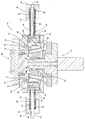
도 1은 본 발명의 현재의 바람직한 일 실시예에 따라 외부 패널 몰드를 가지는 몰드 머신의 단면도이다.
도 2는 개방 위치에 있는 것으로 나타나 있는 도 1의 외부 패널 몰드의 사시도이다.
도 3은 중간 위치에 있는 외부 패널 몰드가 나타나 있는 도 2와 유사한 도면이다.
도 4는 폐쇄 위치에 있는 외부 패널 몰드가 나타나 있는 도 2와 유사한 도면이다.
도 5는 좌측이 폐쇄 위치에 있고 우측이 개방 위치에 있는 외부 패널 몰드가 나타나 있는 외부 패널 몰드의 구동 부재들을 통과하여 절단된 단면도이다.
도 6은 좌측이 폐쇄 위치에 있고 우측이 개방 위치에 있는 외부 패널 몰드가 나타나 있는 외부 패널 몰드의 가이드 부재들을 통과하여 절단된 단면도이다.
도 6a는 본 발명의 다른 양태에 따라 제조되는 외부 패널 몰드에 관한 도 6과 유사한 도면이다. Various aspects, features and advantages of the invention will be considered in conjunction with the following detailed description of the invention, the appended claims, and the accompanying drawings, relating to the presently preferred embodiments and the best embodiments thereof. Will be easily understood.
1 is a cross-sectional view of a mold machine having an outer panel mold in accordance with a presently preferred embodiment of the present invention.
2 is a perspective view of the outer panel mold of FIG. 1 shown to be in the open position;
FIG. 3 is a view similar to FIG. 2 showing the outer panel mold in an intermediate position.
FIG. 4 is a view similar to FIG. 2 showing the outer panel mold in the closed position.
5 is a cross-sectional view cut through the drive members of the outer panel mold with the outer panel mold shown with the left side in the closed position and the right side in the open position;
6 is a cross-sectional view cut through the guide members of the outer panel mold with the outer panel mold shown with the left side in the closed position and the right side in the open position;
FIG. 6A is a view similar to FIG. 6 for an outer panel mold made in accordance with another aspect of the present invention. FIG.
도면들에 대하여 보다 상세하게 참조하면, 도 1에는 피스톤의 상부 크라운부를 성형하도록 구성되어 있는 몰드 머신으로서 헤드 코어라고도 지칭되는 탑 코어(12)를 가지는 종래 또는 표준 몰드 머신과 같은 몰드 머신(10), 피스톤의 내부 표면들을 성형하도록 구성된 메인 코어(14), 및 본 발명의 일 양태에 따라 제조되는 한 쌍의 직경방향으로 반대쪽에 있는 외부 패널들(18, 20)을 가지는 외부 패널 몰드(16)가 도시되어 있다. 외부 패널 몰드(16)는 종래의 몰드 머신(10)을, 피스톤 헤드의 하부 표면 속으로 뻗어 있는 복잡한 언더컷 냉각 갤러리들을 몰딩할 수 있는 몰드 머신으로 용이하게 변환시키는 성능을 제공하고, 이로써 원하는 바와 같이 복잡한 형상의 외부 냉각 갤러리들을 가지는 피스톤들을 성형할 수 있는 신속하면서도 경제적인 방법을 제공하는 것이 가능하다. 언더컷 냉각 갤러리들은 이와 다른 방법으로 표준 피스톤 몰드 머신으로 달성가능한 다수의 복잡한 형태들 및 형상들을 가지도록 성형될 수 있다. 예를 들어, 언더컷 냉각 갤러리들은 외부 패널들(18, 20)에 관하여 이하에서 설명되는 메커니즘 때문에 피스톤의 핀 보스들의 외부면들 속으로 반경방향 위쪽과 반경방향 안쪽으로 뻗어 있을 수 있고, 이로써 서로를 향하여 수렴하는 직경방향으로 반대쪽에 있는 외부 냉각 갤러리들을 성형하는 것이 가능한데, 이는 위의 관련 기술 분야에서 설명된 것과 같은 복잡한 피벗 메커니즘들을 포함해야만 하는 상황과는 무관하되 단일의 피스톤 구성을 만들도록 특별히 설계된 복잡한 전용 피스톤 몰드 머신을 사용해야만 하는 상황에 의해 가능하다. 따라서, 외부 패널 몰드(16)는 신속하면서도 경제적인 장치와 방법을 제공하는데, 이로써 핀 보스들의 자유 단부들을 향하여 바깥쪽으로 발산하거나 돌출되어 있는 직경방향으로 반대쪽에 있는 핀 보스들의 마주하는 외부면들 속으로 적어도 부분적으로 뻗어 있는 복잡한 외부 냉각 갤러리들을 가지는 피스톤들을 몰딩하도록 종래의 피스톤 몰드 머신을 용이하게 변환시킬 수 있는 한편, 이와 동시에 종래의 몰드 머신으로 과도한 비용을 들이지 않고도 종래의 피스톤들을 몰딩하는 것이 용이하게 되는 것을 가능하게 한다. Referring to the drawings in more detail, FIG. 1 shows a
탑 코어(12)와 메인 코어(14)는 원하는 바와 같이 피스톤의 상부 크라운 및 내부 부재들을 몰딩하기 위해서 표준 몰드 머신(10)의 표준 구성요소들로서 제공될 수 있다. 탑 코어(12)와 메인 코어(14)는 알려진 바와 같이 몰딩된 피스톤의 중심 축에 대응하는 길이방향 중심 축(22)을 따라 맞물림해제 위치와 맞물림 위치 사이에서 수직방향으로 이동한다. 몰딩된 피스톤은 각각의 맞물림해제 위치들 쪽으로 이동될 때 몰드 구성요소들과의 간섭과는 무관하게 몰드 캐비티(24)로부터 완전히 수직방향으로 아래쪽으로 이동될 수 있다. 이는 대부분, 이하에서 설명되는 외부 패널 몰드(16)의 구성에 좌우되어 길이방향 중심 축(22)에 대하여 비스듬하게 뻗어 있는 축을 따라 또는 길이방향 중심 축(22)에 대해 평행하거나 실질적으로 평행한 축을 따라 외부 패널 몰드(16)의 패널들(18, 20)을 각각의 냉각 갤러리들로부터 바깥쪽으로 이동시키는 성능 때문이다. The
도 2 내지 도 4에 가장 잘 나타나 있는 바와 같이, 외부 패널 몰드(16)는 이하에서 핀 코어 구동 블록으로 지칭되는 한 쌍의 거전 핀 코어 구동 블록(gudgeon pin core dirve block)(26)들, 및 이하에서 핀 보어 맨드럴(mandrel) 또는 핀 보어 코어로도 지칭되는 한 쌍의 대응하는 거전 핀 코어(28)들을 포함한다. 핀 코어 구동 블록(26) 각각은 리니어 액추에이터(미도시)에 작동가능하게 부착되도록 구성된 한쪽 측면(30), 및 제한없는 예로써 도브테일형(dovetail-type) 조인트 연결수단을 통해 연결되는 것으로 나타나 있는 핀 보어 코어(28)의 단부(34)에 작동가능하게 부착되도록 구성된 반대쪽 측면(32)을 포함한다. 핀 코어 구동 블록(26)들은 또한 바닥면 또는 베이스(38) 쪽으로 뻗어 있는 한 쌍의 오목한 보어들 또는 포켓(36)들을 포함한다(도 5). 베이스(38)들은 대응하는 가이드 로드(42)를 미끄러지듯 수용하도록 관통하여 뻗어 있는 감소된 직경의 관통 개구부(40)들을 가지고, 여기서 각 가이드 로드(42)의 한쪽 단부(43)는, 예컨대 핀(46)들을 통해 가이드 블록(44)으로도 지칭되는 핀 코어 가이드 블록에 작동가능하게 고정된다. 포켓(36)들은 대응하는 스프링 부재(48)들을 부분적으로 수용하도록 구성되어 있는데, 이 스프링 부재들은 바닥면(38)과 접촉하고, 적어도 가이드 블록(44)과 약간 압축되어 접촉하도록 포켓(36)들로부터 바깥쪽으로 뻗어 있다. As best shown in FIGS. 2-4, the
가이드 블록(44)들은 관통하여 뻗어 있는, 중심에 위치되는 관통 보어(56)를 구비한 양쪽 측면들(52, 54)을 가진다. 관통 보어(56)들은 관통하여 핀 보어 코어(28)들을 미끄러지듯 정확히 수용하는 크기를 가진다. 따라서, 핀 코어 구동 블록(26)들의 이동시, 핀 보어 코어(28)들은 맞물림 위치와 맞물림해제 위치(각각 도 2 및 도 4) 사이에서 관통 보어(56)들을 통해 자유롭게 미끄럼이동한다.The guide blocks 44 have both
가이드 블록(44)들은 한 쌍의 피구동 부재(58)들과 한 쌍의 구동 부재(60)들을 가진다. 피구동 부재(58)들은 가이드 블록(44)들에 고정되고, 핀 보어 코어(28)들의 축방향 운동에 응답하여 선택적으로 구동되어 외부 패널들(18, 20)들을 함께 이동시킨다. 피구동 부재(58)들은 제한없는 예로써 가이드 블록(44)들에 대해 단단히 고정되어 있는, 수직방향으로 뻗어 있는 핀들로서 나타나 있다. 구동 부재(60)들은 구동 부재(60)들이 그 내부에 정확히 들어맞는(close fit) 크기를 가지는 가이드 블록(44)들 내의 대응하는 통로(62)들에 수용된다. 구동 부재(60)들은 제한없는 예로써 핀(64)들과 같은 것을 통해 통로(62)들 내에 고정된다. 통로(62)들, 결과적으로는 구동 부재(60)들은 길이방향 중심 축(22)에 대해 비스듬한 각도로 뻗어 있는데, 여기서는 축(22)에 대하여 약 30 도 내지 60 도 사이에 뻗어 있는 것으로 나타나 있되, 원하는 바와 같이 이 범위를 벗어나는 각도가 제공될 수도 있다. 구동 부재(60)들이 위쪽과 반경방향 바깥쪽으로 뻗어 있도록, 결과적으로는 이 구동 부재들이 하부 단부들로부터 상부 단부들을 향하여 서로로부터 발산하도록, 경사각은 배향되어 있다. The guide blocks 44 have a pair of driven
내부 표면(66)들을 가지는 외부 패널들(18, 20)은 핀 보스 외부면들의 원하는 형상을 성형하도록 윤곽형성되어 있다. 또한, 외부 패널들은 위쪽을 향하여 뻗어 있는 돌출부(68)들을 가지는데, 이 돌출부들은 외부 패널들에 의해 성형된 외부 냉각 갤러리들의 원하는 형상에 대해 네거티브한 것과 같은 형상을 가진다. 외부 패널들에 의해 성형된 외부 냉각 갤러리들이 그로부터 인접하여 늘어져 있는 핀 보스의 외부면에 대하여 축방향 위쪽과 반경방향 안쪽으로 뻗어 있도록, 돌출부(68)들은 축방향 위쪽과 반경방향 안쪽으로 뻗어 있을 수 있다. 보통, 이러한 구성의 형상을 가지는 냉각 갤러리는 그로부터 네거티브 몰드 돌출부를 제거하기 위하여 정교한 피벗 메커니즘 또는 전용 몰드 머신을 필요로 할 수 있지만, 본 발명의 일 양태에 따르는 외부 패널들(18, 20)은 가이드 핀들로도 지칭되는 한 쌍의 외부 패널 가이드 부재(70)들을 통해 일직선 경로를 따라 안내될 수 있다. 가이드 핀(70)들이 길이방향 중심 축(22)을 향하여 대체로 축방향 위쪽과 반경방향 안쪽으로 뻗어 있는 것과 같이 길이방향 중심 축(22)에 대하여 비스듬하게 뻗어 있을 수 있도록(도 6), 또는 길이방향 중심 축(22)과 평행하거나 실질적으로 평행하게 뻗어 있을 수 있도록(도 6a), 가이드 핀(70)들은 원하는 경사각을 따라 뻗어 있도록 배향될 수 있다. 가이드 핀(70)들은 그 내부에서 미끄러지듯 정확히 들어맞게 관통 통로(76)들을 통해 하부면(72)과 상부면(74)을 관통하여 뻗어 있다. 따라서, 관통 통로(76)들은 부싱들과 같은 역할을 하고, 이를 통해 가이드 부재(70)들은 핀 코어 가이드 블록(44)의 구동 부재(60)들에 의해 구동되는 외부 패널들(18, 20)에 응답하여 미끄럼이동한다. 가이드 핀(70)들은 상부 플레이트(78)와 하부 플레이트(80)에 의해 양쪽 단부들에서 파지되는 한편, 중간 플레이트(82)는 외부 패널 몰드(16)를 구획하거나 실질적으로 구획한다. The
외부 패널들(18, 20)은 관통하여 구동 부재(60)들을 미끄러지듯 정확히 수용하는 크기를 가지는 관통 통로(84)들을 더 포함하는데, 관통 통로들은 예로써 부싱(85)들과 정렬되어 있는 것으로 나타나 있다. 관통 통로(84)들, 결과적으로는 구동 부재(60)들은 길이방향 중심 축(22)에 대하여 비스듬하게 뻗어 있는데, 중심 축(22)으로부터 축방향 위쪽과 반경방향 바깥쪽으로 뻗어 있는 바와 같이 나타나 있다. 또한 외부 패널들(18, 20)은 맞물림 위치와 맞물림해제 위치 사이에서 이동할 때 핀 보어 코어(28)들을 미끄러지듯 정확히 수용하는 크기를 가지는 관통 개구부(86)들을 각각 포함한다. 핀 보어 코어(28)들이 완전히 맞물림 위치에 있을 때, 핀 보어 코어(28)들의 자유 단부들은 내부 표면(66)들을 넘어 뻗어서 몰딩 동안 핀 보스들 내에 거전 핀 보어들을 성형한다. The
핀 보어 코어(28)들은 양쪽 단부들(90, 92) 사이에 뻗어 있는 중심부(88)를 가진다. 중심부(88)는 양쪽 숄더들(96, 98) 사이에 축방향으로 뻗어 있되 직경방향으로 반대쪽에 있는 한 쌍의 오목한 노치(94)들로 나타나 있는 오목한 노치를 포함한다. 오목한 노치(94)들은 피구동 부재(58)들을 그 내부에 수용하도록 윤곽형성되어 있다. 숄더들(96, 98)은 오목한 노치(94)들로부터 바깥쪽으로 뻗어 있어서 피구동 부재(58)들에 접촉하는 한편, 아래에서 추가로 설명되는 바와 같이 외부 패널 몰드(16)를 폐쇄하고 개방한다. The pin bore
작동시, 몰드 머신(10)이 개방 및 맞물림해제 위치에 있는 상태에서, 액추에이터(미도시)는 핀 코어 구동 블록(26)들 상에서 반경방향 안쪽을 밀도록 작동되고, 이는 차례로 핀 보어 코어(28)들을 반경방향 안쪽으로 함께 이동시킨다. 핀 보어 코어(28)들이 동축방향으로 서로를 향하여 전진할 때, 충분한 스프링 힘을 가지는 스프링 부재(48)들은 가이드 블록(44)들을 외부 패널들(18, 20)을 향하여 축방향으로 이동시키고, 이는 차례로 구동 부재들(58, 60)을 대응하는 관통 통로(84)들을 통해 미끄럼이동시키고, 이는 차례로 외부 패널들(18, 20)을 가이드 부재(70)들을 따라 수직방향 위쪽과 반경방향 안쪽으로 구동시킨다. 외부 패널들(18, 20)이 폐쇄 위치로 이동하고 핀 코어 가이드 블록(44)들이 외부 패널들(18, 20)들과 접촉할 때, 피구동 부재(58)들이 오목한 노치(94)들을 횡단함에 따라, 핀 보어 코어(28)들의 축방향 이동은 계속된다. 그 후, 피구동 부재(58)들이 숄더(96)들과 맞물릴 때, 외부 패널들(18, 20)은 폐쇄 위치로 고정된다. In operation, with the
탑 코어(12)와 메인 코어(14)는 각각의 폐쇄 위치들로 이동되고, 그 후 적합한 액체 피스톤 몰드 재료는 몰드 캐비티(24) 속으로 도입된다. 몰드 재료는 충분히 냉각되는 것이 허용되고, 그 후 몰드는 개방되어 피스톤이 몰드 캐비티(24)로부터 수직방향 위쪽으로 제거되는 것을 허용한다.
몰드 캐비티(24)를 개방하는 것을 개시하기 위하여, 몰드 구성요소들을 폐쇄하는 것의 순서는 반드시 역전된다. 따라서, 액추에이터(미도시)는 후퇴되어 핀 보어 구동 블록(26)들 상에서 반경방향 바깥쪽을 잡아 당기고, 이는 차례로 핀 보어 코어(28)들을 반경방향 바깥쪽으로 함께 이동시킨다. 핀 보어 코어(28)들이 서로로부터 멀리 동축방향으로 후퇴할 때, 충분한 스프링 힘을 가지는 스프링 부재(48)들은 가이드 블록(44)들을 외부 패널들(18, 20)과 접촉하도록 유지시키고, 오목한 노치(94)들은 숄더(98)들이 피구동 부재(58)들과 맞물릴 때까지 피구동 부재(58)들을 따라 이동한다. 숄더(98)들이 피구동 부재(58)들과 맞물릴 때, 숄더(98)들은 피구동 부재(58)들을 축방향 바깥쪽으로 잡아 당기고, 이는 차례로 핀 코어 가이드 블록(44)들을 핀 보어 코어(28)들과 함께 이동시킨다. 가이드 블록(44)들의 이동은 대응하는 관통 통로(84)들을 통해 미끄럼이동하는 구동 부재들(58, 60)을 함께 이동시키고, 이는 차례로 외부 패널들(18, 20)을 가이드 부재(70)들을 따라 수직방향 아래쪽과 반경방향 바깥쪽으로 구동시킨다. 외부 패널들(18, 20)들이 개방 위치로 이동하고 탑 코어(12)와 메인 코어(14)가 대응하는 후퇴 위치들 쪽으로 수직방향으로 이동될 때, 피스톤은 개방 몰드 캐비티(24)로부터 수직방향 바깥쪽으로 자유롭게 상승된다. In order to commence opening the
본 발명의 또 다른 양태에 따르면, 언더컷 냉각 갤러리를 피스톤 내에 성형하는 방법이 제공된다. 이 방법은 한 쌍의 거전 코어 부재(28)들을 공통 거전 핀 축을 따라 각각의 거전 가이드 블록(44)들을 통해 맞물림 위치 쪽으로 서로를 향하여 이동시키는 단계를 포함한다. 이 방법은 거전 코어 부재(28)들을 그 맞물림 위치를 향하여 이동시키면서 거전 가이드 블록(44)들을 거전 핀 축을 따라 서로를 향하여 구동시키는 단계를 더 포함한다. 또한 이 방법은 한 쌍의 외부 패널들(18, 20)을 거전 가이드 블록(44)들의 이동에 응답하여 폐쇄 위치로 구동시키는 단계를 더 포함한다. 이 방법은 그 후, 언더컷 냉각 갤러리를 성형하기 위해서 외부 패널들(18, 20)의 상부(68)들 둘레에 유체 피스톤 재료를 몰딩하는 단계를 포함한다. 이 방법은 그 후, 거전 코어 부재(28)들을 거전 핀 축을 따라 맞물림해제 위치 쪽으로 서로로부터 멀리 이동시키는 단계를 포함한다. 이 방법은 거전 가이드 블록(44)들을 그 맞물림해제 위치를 향하되 거전 코어 부재(28)들의 이동에 응답하여 거전 핀 축을 따라 서로로부터 멀리 구동시키는 단계를 더 포함한다. 이 방법은 그 후, 외부 패널들(18, 20)을 거전 가이드 블록(44)들의 이동에 응답하여 개방 위치로 구동시키는 단계를 포함한다. According to another aspect of the invention, a method of forming an undercut cooling gallery in a piston is provided. The method includes moving the pair of
언더컷을 성형하는 방법의 추가적인 양태는 다음의 단계들, 즉 외부 패널들(18, 20)을 거전 가이드 블록(44)들의 이동에 응답하여 부재들(60, 70)을 따라 미끄럼이동시키는 단계; 거전 핀 축에 대하여 비스듬하게 뻗도록 부재들(60, 70)을 배향하는 단계; 거전 코어 부재(28)들이 그 맞물림 위치와 맞물림해제 위치 사이에서 적어도 부분적으로 이동하는 동안 거전 코어 부재(28)들을 거전 가이드 블록(44)들에 대하여 이동시키는 단계; 거전 코어 부재(28)들이 그 맞물림 위치와 맞물림해제 위치 사이에서 적어도 부분적으로 이동하는 동안 거전 가이드 블록(44)들을 거전 코어 부재(28)들과 함께 이동시키는 단계; 외부 패널들(18, 20)을 거전 핀 축에 비스듬한 수렴형 직선 경로를 따라 폐쇄 위치를 향하여 이동시키는 단계; 및 외부 패널들(18, 20)을 거전 핀 축에 비스듬한 발산형 직선 경로를 따라 서로로부터 멀리 개방 위치를 향하여 이동시키는 단계;를 포함할 수 있다. A further aspect of the method of forming an undercut includes the following steps: sliding the
본 발명의 또 다른 양태에 따르면, 피스톤을 제조하는 방법이 제공된다. 이 방법은 종래의 몰드 머신을 제공하는 단계와 외부 패널 몰드(16)를 몰드 머신에 부착하는 단계를 포함한다. 외부 패널 몰드(16)는 한 쌍의 거전 코어 부재(28)들, 한 쌍의 거전 가이드 블록(44)들 및 한 쌍의 외부 패널들(18, 20)을 포함한다. 이 방법은 쌍을 이루는 거전 코어 부재(28)들을 맞물림 위치 쪽으로 공통 거전 핀 축을 따라 각각의 거전 가이드 블록(44)들을 통해 서로를 향하여 이동시키는 단계를 더 포함한다. 이 방법은 그 후, 거전 코어 부재(28)들이 그 맞물림 위치를 향하여 이동하고 있는 동안, 거전 가이드 블록(44)들을 거전 핀 축을 따라 서로를 향하여 구동시키는 단계를 포함한다. 이 방법은 쌍을 이루는 외부 패널들(18, 20)을 거전 가이드 블록(44)들의 이동에 응답하여 폐쇄 위치로 구동시키는 단계를 더 포함한다. 이 방법은 그 후, 피스톤 바디를 성형하기 위해서는 몰드 캐비티(24) 내부에, 그리고 피스톤 바디 내부에 언더컷 냉각 갤러리를 성형하기 위해서는 외부 패널들(18, 20)의 상부(68)들 둘레에 유체 피스톤 재료를 몰딩하는 단계를 포함한다. 또한 이 방법은 거전 코어 부재(28)들을 거전 핀 축을 따라 맞물림해제 위치 쪽으로 서로로부터 멀리 이동시키는 단계를 더 포함한다. 이 방법은 그 후, 거전 가이드 블록(44)들을 그 맞물림해제 위치를 향하되 거전 코어 부재(28)들의 이동에 응답하여 거전 핀 축을 따라 서로로부터 멀리 구동시키는 단계를 포함한다. 이 방법은 외부 패널들(18, 20)을 거전 가이드 블록(44)들의 이동에 응답하여 개방 위치로 구동시키는 단계를 더 포함한다. 이 방법은 그 후, 피스톤 바디를 몰드 캐비티(24)로부터 제거하는 단계를 포함한다. According to another aspect of the invention, a method of manufacturing a piston is provided. The method includes providing a conventional mold machine and attaching the
피스톤을 제조하는 방법의 추가적인 양태는 다음의 단계들, 즉 외부 패널들(18, 20)을 거전 가이드 블록(44)들의 이동에 응답하여 부재들(60, 70)을 따라 미끄럼이동시키는 단계; 거전 핀 축에 대하여 비스듬하게 뻗도록 부재들(60, 70)을 배향하는 단계; 거전 코어 부재(28)들이 그 맞물림 위치와 맞물림해제 위치 사이에서 적어도 부분적으로 이동하는 동안 거전 코어 부재(28)들을 거전 가이드 블록(44)들에 대하여 이동시키는 단계; 거전 코어 부재(28)들이 그 맞물림 위치와 맞물림해제 위치 사이에서 적어도 부분적으로 이동하는 동안 거전 가이드 블록(44)들을 거전 코어 부재(28)들과 함께 이동시키는 단계; 및 외부 패널들(18, 20)을 거전 핀 축에 비스듬한 수렴형 직선 경로를 따라 폐쇄 위치를 향하여 이동시키는 단계; 외부 패널들(18, 20)을 거전 핀 축에 비스듬한 발산형 직선 경로를 따라 개방 위치를 향하여 이동시키는 단계;를 포함할 수 있다. Additional aspects of the method of manufacturing the piston include the following steps: sliding the
위에서 상술된 발명의 상세한 설명이 현재의 바람직한 일부 실시예들에 관한 것이라는 점, 및 동일한 기능을 달성하는 다른 실시예들이 궁극적으로 허용되는 특허청구범위들의 범위 내에서 본 명세서에 통합되어 있다는 점은 이해할 수 있을 것이다. It is to be understood that the above detailed description of the invention relates to some presently preferred embodiments, and that other embodiments achieving the same functionality are ultimately incorporated herein within the scope of the appended claims. Could be.
Claims (26)
한 쌍의 거전 코어 부재들;
맞물림 위치와 맞물림해제 위치 사이에서 피스톤의 길이방향 중심 축에 대해 실질적으로 수직하는 직선 경로를 따라 서로를 향하여 그리고 서로로부터 멀리 이동가능한 한 쌍의 거전 가이드 블록들로서, 각각의 상기 거전 가이드 블록들은 그 내부에서의 미끄럼이동가능한 이동을 위하여 상기 거전 코어 부재들 중 별개의 하나를 수용하는 개구부를 가지는, 한 쌍의 거전 가이드 블록들; 및
각각의 상기 거전 가이드 블록에 각각 작동가능하게 연결되고, 피스톤의 언더컷 냉각 갤러리를 성형하기 위해서 상기 쌍을 이루는 거전 가이드 블록들 사이에서 폐쇄 위치로 수직방향으로 이동가능한 한 쌍의 외부 패널들로서, 상기 외부 패널들은 상기 길이방향 중심 축을 따라 수직방향으로 피스톤을 빼내기 위해서 개방 위치 쪽으로 수직방향으로 이동가능하고, 상기 외부 패널들은 상기 거전 가이드 블록들의 이동에 응답하여 상기 개방 위치와 폐쇄 위치 사이에서 이동가능한, 한 쌍의 외부 패널들;
을 구비하는 것을 특징으로 하는 피스톤 외부 패널 몰드.A piston outer panel mold operably attachable to a conventional piston mold machine, wherein the piston outer panel mold is:
A pair of geothermal core members;
A pair of force guide blocks moveable toward and away from each other along a straight path substantially perpendicular to the longitudinal center axis of the piston between the engaged position and the disengaged position, each of the force guide blocks being inside thereof. A pair of force guide blocks having an opening for receiving a separate one of the force core members for slidable movement in the arm; And
A pair of outer panels operatively connected to each of the ground guide blocks, the pair of outer panels movable vertically to a closed position between the pair of ground guide blocks for forming an undercut cooling gallery of a piston, the outer The panels are movable vertically towards the open position to withdraw the piston in the vertical direction along the longitudinal center axis, and the outer panels are movable between the open position and the closed position in response to the movement of the coarse guide blocks. A pair of outer panels;
A piston outer panel mold comprising a.
각각의 상기 거전 가이드 블록들에 고정되는 적어도 하나의 구동 부재를 더 포함하고, 상기 외부 패널들은 그 내부에서의 미끄럼이동가능한 이동을 위하여 상기 적어도 하나의 구동 부재를 수용하는 개구부를 가지는 것을 특징으로 하는 피스톤 외부 패널 몰드.The method of claim 1,
Further comprising at least one drive member secured to each of the coarse guide blocks, the outer panels having an opening for receiving the at least one drive member for slidable movement therein. Piston outer panel mold.
각각의 상기 외부 패널들은 상기 적어도 하나의 구동 부재의 이동에 응답하여 그 개방 위치와 폐쇄 위치 사이에서 상기 적어도 하나의 구동 부재를 따라 이동하는 것을 특징으로 하는 피스톤 외부 패널 몰드.The method of claim 2,
And each said outer panel moves along said at least one drive member between its open and closed positions in response to movement of said at least one drive member.
상기 적어도 하나의 구동 부재는 상기 길이방향 중심 축에 대하여 비스듬하게 뻗어 있는 것을 특징으로 하는 피스톤 외부 패널 몰드.The method of claim 3, wherein
And said at least one drive member extends obliquely with respect to said longitudinal central axis.
상기 거전 가이드 블록들은 상기 거전 코어 부재들의 이동에 응답하여 그 맞물림 위치로부터 그 맞물림해제 위치 쪽으로 이동하는 것을 특징으로 하는 피스톤 외부 패널 몰드.The method of claim 3, wherein
And wherein the force guide blocks move from their engagement position toward their disengagement position in response to movement of the force core members.
각각의 상기 거전 가이드 블록들은 적어도 하나의 피구동 부재를 가지고, 상기 거전 코어 부재들은 양쪽 숄더들 사이에 뻗어 있는 오목한 노치를 가지는 것을 특징으로 하는 피스톤 외부 패널 몰드.The method of claim 5,
Wherein each of the force guide blocks has at least one driven member, the force core members having a concave notch extending between both shoulders.
상기 거전 코어 부재들은 상기 피구동 부재가 상기 숄더들로부터 이격될 때 상기 거전 가이드 블록들에 대하여 이동가능한 것을 특징으로 하는 피스톤 외부 패널 몰드.The method of claim 6,
And wherein the governing core members are movable relative to the governing guide blocks when the driven member is spaced apart from the shoulders.
상기 거전 가이드 블록들은 상기 피구동 부재가 상기 숄더들 중 하나와 접촉할 때 상기 거전 코어 부재들과 함께 이동하는 것을 특징으로 하는 피스톤 외부 패널 몰드.The method of claim 6,
And the force guide blocks move together with the force core members when the driven member contacts one of the shoulders.
상기 쌍을 이루는 외부 패널들은 상기 폐쇄 위치를 향하여 수렴형 직선 경로를 따라 서로를 향하여 이동가능하고, 상기 개방 위치 쪽으로 발산형 직선 경로를 따라 서로로부터 멀리 이동가능한 것을 특징으로 하는 피스톤 외부 패널 몰드.The method of claim 1,
And the paired outer panels are movable towards each other along a converging straight path towards the closed position and distant from each other along a divergent straight path towards the open position.
상기 쌍을 이루는 외부 패널들은 관통하여 뻗어 있는 적어도 하나의 관통 개구부를 가진 상부면과 하부면을 가지고, 상기 적어도 하나의 관통 개구부는 가이드 부재를 그 내부에서 느슨하게 들어맞게(loose fit) 수용하고, 그리고 상기 외부 패널들은 상기 적어도 하나의 구동 부재의 이동에 응답하여 상기 가이드 부재를 따라 미끄럼이동하는 것을 특징으로 하는 피스톤 외부 패널 몰드.The method of claim 2,
The pair of outer panels have an upper surface and a lower surface having at least one through opening extending therethrough, the at least one through opening receiving a loose fit therein, and And the outer panels slide along the guide member in response to movement of the at least one drive member.
상기 가이드 부재는 상기 길이방향 중심 축에 대하여 비스듬하게 뻗어 있는 것을 특징으로 하는 피스톤 외부 패널 몰드.The method of claim 10,
And the guide member extends obliquely with respect to the longitudinal central axis.
상기 가이드 부재는 상기 길이방향 중심 축을 향하여 축방향 위쪽과 반경방향 안쪽으로 뻗어 있도록 경사진 것을 특징으로 하는 피스톤 외부 패널 몰드.The method of claim 11,
And the guide member is inclined to extend axially upward and radially inward toward the longitudinal central axis.
한 쌍의 거전 코어 부재들을 피스톤의 길이방향 중심 축에 대해 실질적으로 수직한 공통 거전 핀 축을 따라 각각의 거전 가이드 블록들을 통해 맞물림 위치 쪽으로 서로를 향하여 이동시키는 단계;
거전 코어 부재들을 그 맞물림 위치를 향하여 이동시키면서 거전 가이드 블록들을 거전 핀 축을 따라 서로를 향하여 구동시키는 단계;
거전 가이드 블록들의 이동에 응답하여 한 쌍의 외부 패널들을 구동시키고 외부 패널들을 수직방향으로 폐쇄 위치로 이동시키는 단계로서, 외부 패널들은 각각의 상기 거전 가이드 블록에 작동가능하게 연결되는 단계;
언더컷 냉각 갤러리를 성형하기 위해서 외부 패널들의 상부들 둘레에 유체 피스톤 재료를 몰딩하는 단계;
거전 코어 부재들을 거전 핀 축을 따라 맞물림해제 위치 쪽으로 서로로부터 멀리 이동시키는 단계;
거전 가이드 블록들을 그 맞물림해제 위치를 향하되 거전 코어 부재들의 이동에 응답하여 거전 핀 축을 따라 서로로부터 멀리 구동시키는 단계; 및
외부 패널들을 거전 가이드 블록들의 이동에 응답하여 개방 위치로 구동시키는 단계;
를 구비하는 것을 특징으로 하는 방법.A method of forming an undercut cooling gallery in a piston, the method comprising:
Moving the pair of force core members toward each other toward the engaged position through respective force guide blocks along a common force pin axis substantially perpendicular to the longitudinal center axis of the piston;
Driving the coarse guide blocks towards each other along the coarse pin axis while moving the coarse core members toward their engagement position;
Driving a pair of outer panels in response to movement of the force guide blocks and moving the outer panels to a closed position in a vertical direction, the outer panels being operably connected to each of the force guide blocks;
Molding a fluid piston material around the tops of the outer panels to form the undercut cooling gallery;
Moving the core core members away from each other toward the disengaged position along the force pin axis;
Driving the engagement guide blocks toward their disengaged position but away from each other along the engagement pin axis in response to movement of the engagement core members; And
Driving the outer panels to an open position in response to movement of the coarse guide blocks;
Method comprising a.
외부 패널들을 거전 가이드 블록들의 이동에 응답하여 부재들을 따라 미끄럼이동시키는 단계를 더 포함하는 것을 특징을 하는 방법.The method of claim 13,
Sliding the outer panels along the members in response to movement of the force guide blocks.
거전 핀 축에 대하여 비스듬하게 뻗도록 부재들을 배향하는 단계를 더 포함하는 것을 특징으로 하는 방법.The method of claim 14,
Orienting the members so as to extend obliquely with respect to the coagulation pin axis.
거전 코어 부재들이 그 맞물림 위치와 맞물림해제 위치 사이에서 적어도 부분적으로 이동하는 동안 거전 코어 부재들을 거전 가이드 블록들에 대하여 이동시키는 단계를 더 포함하는 것을 특징으로 하는 방법.The method of claim 13,
Moving the core core members relative to the force guide blocks while the core core members are at least partially moving between their engaged and disengaged positions.
거전 코어 부재들이 그 맞물림 위치와 맞물림해제 위치 사이에서 적어도 부분적으로 이동하는 동안 거전 가이드 블록들을 거전 코어 부재들과 함께 이동시키는 단계를 더 포함하는 것을 특징으로 하는 방법.The method of claim 16,
Moving the engagement guide blocks with the engagement core members while the engagement core members are at least partially moving between their engagement and disengagement positions.
외부 패널들을 거전 핀 축에 비스듬한 수렴형 직선 경로를 따라 폐쇄 위치를 향하여 이동시키는 단계를 더 포함하는 것을 특징으로 하는 방법.The method of claim 13,
Moving the outer panels toward the closed position along a converging straight path oblique to the coarse pin axis.
외부 패널들을 거전 핀 축에 비스듬한 발산형 직선 경로를 따라 서로로부터 멀리 개방 위치를 향하여 이동시키는 단계를 더 포함하는 것을 특징으로 하는 방법.The method of claim 18,
Moving the outer panels toward an open position away from each other along a divergent straight path oblique to the force pin axis.
종래의 몰드 머신을 제공하는 단계;
한 쌍의 거전 코어 부재들, 한 쌍의 거전 가이드 블록들 및 한 쌍의 외부 패널들을 포함하는 외부 패널 몰드를 몰드 머신에 부착하는 단계;
쌍을 이루는 거전 코어 부재들을 맞물림 위치 쪽으로 공통 거전 핀 축을 따라 각각의 거전 가이드 블록들을 통해 서로를 향하여 이동시키는 단계;
거전 코어 부재들이 그 맞물림 위치를 향하여 이동하고 있는 동안, 거전 가이드 블록들을 거전 핀 축을 따라 서로를 향하여 구동시키는 단계;
쌍을 이루는 외부 패널들을 거전 코어 블록들의 이동에 응답하여 폐쇄 위치로 구동시키는 단계;
피스톤 바디를 성형하기 위해서는 몰드 캐비티 내부에, 그리고 피스톤 바디 내부에 언더컷 냉각 갤러리를 성형하기 위해서는 외부 패널들의 상부들 둘레에 유체 피스톤 재료를 몰딩하는 단계;
거전 코어 부재들을 거전 핀 축을 따라 맞물림해제 위치 쪽으로 서로로부터 멀리 이동시키는 단계;
거전 가이드 블록들을 그 맞물림해제 위치를 향하되 거전 코어 부재들의 이동에 응답하여 거전 핀 축을 따라 서로로부터 멀리 구동시키는 단계;
외부 패널들을 거전 코어 블록들의 이동에 응답하여 개방 위치로 구동시키는 단계; 및
피스톤 바디를 몰드 캐비티로부터 제거하는 단계;
를 구비하는 것을 특징으로 하는 방법.As a method of manufacturing a piston,
Providing a conventional mold machine;
Attaching an outer panel mold to the mold machine, wherein the outer panel mold comprises a pair of force core members, a pair of force guide blocks and a pair of outer panels;
Moving the paired force core members toward each other through respective force guide blocks along a common force pin axis toward the engaged position;
Driving the coarse guide blocks toward each other along the coarse pin axis while the coarse core members are moving toward their engagement position;
Driving the pair of outer panels to a closed position in response to movement of the coarse core blocks;
Molding a fluid piston material around the tops of the outer panels to mold the piston body inside the mold cavity and to form the undercut cooling gallery inside the piston body;
Moving the core core members away from each other toward the disengaged position along the force pin axis;
Driving the engagement guide blocks toward their disengaged position but away from each other along the engagement pin axis in response to movement of the engagement core members;
Driving the outer panels to an open position in response to movement of the coarse core blocks; And
Removing the piston body from the mold cavity;
Method comprising a.
외부 패널들을 거전 가이드 블록들의 이동에 응답하여 부재들을 따라 미끄럼이동시키는 단계를 더 포함하는 것을 특징으로 하는 방법.The method of claim 20,
Sliding the outer panels along the members in response to movement of the coarse guide blocks.
거전 핀 축에 대하여 비스듬하게 뻗도록 부재들을 배향하는 단계를 더 포함하는 것을 특징으로 하는 방법.The method of claim 21,
Orienting the members so as to extend obliquely with respect to the coagulation pin axis.
거전 코어 부재들이 그 맞물림 위치와 맞물림해제 위치 사이에서 적어도 부분적으로 이동하는 동안 거전 코어 부재들을 거전 가이드 블록들에 대하여 이동시키는 단계를 더 포함하는 것을 특징으로 하는 방법.The method of claim 20,
Moving the core core members relative to the force guide blocks while the core core members are at least partially moving between their engaged and disengaged positions.
거전 코어 부재들이 그 맞물림 위치와 맞물림해제 위치 사이에서 적어도 부분적으로 이동하는 동안 거전 가이드 블록들을 거전 코어 부재들과 함께 이동시키는 단계를 더 포함하는 것을 특징으로 하는 방법.The method of claim 23,
Moving the engagement guide blocks with the engagement core members while the engagement core members are at least partially moving between their engagement and disengagement positions.
외부 패널들을 거전 핀 축에 비스듬한 수렴형 직선 경로를 따라 폐쇄 위치를 향하여 이동시키는 단계를 더 포함하는 것을 특징으로 하는 방법.The method of claim 20,
Moving the outer panels toward the closed position along a converging straight path oblique to the coarse pin axis.
외부 패널들을 거전 핀 축에 비스듬한 발산형 직선 경로를 따라 개방 위치를 향하여 이동시키는 단계를 더 포함하는 것을 특징으로 하는 방법.The method of claim 25,
Moving the outer panels toward the open position along an divergent straight path oblique to the coarse pin axis.
Applications Claiming Priority (3)
| Application Number | Priority Date | Filing Date | Title |
|---|---|---|---|
| US13/544,978 | 2012-07-09 | ||
| US13/544,978 US8459332B1 (en) | 2012-07-09 | 2012-07-09 | Piston outer panel mold and method of constructing a piston and forming an undercut cooling gallery of a piston therewith |
| PCT/US2013/049025 WO2014011440A2 (en) | 2012-07-09 | 2013-07-02 | Piston outer panel mold and method of constructing a piston and forming an undercut cooling gallery of a piston therewith |
Publications (2)
| Publication Number | Publication Date |
|---|---|
| KR20150030749A KR20150030749A (en) | 2015-03-20 |
| KR102055935B1 true KR102055935B1 (en) | 2019-12-13 |
Family
ID=48538268
Family Applications (1)
| Application Number | Title | Priority Date | Filing Date |
|---|---|---|---|
| KR1020157002819A KR102055935B1 (en) | 2012-07-09 | 2013-07-02 | Piston outer panel mold and method of constructing a piston and forming an undercut cooling gallery of a piston therewith |
Country Status (7)
| Country | Link |
|---|---|
| US (1) | US8459332B1 (en) |
| EP (1) | EP2869952B1 (en) |
| JP (1) | JP6199966B2 (en) |
| KR (1) | KR102055935B1 (en) |
| CN (1) | CN104619440B (en) |
| BR (1) | BR112015000425A2 (en) |
| WO (1) | WO2014011440A2 (en) |
Families Citing this family (3)
| Publication number | Priority date | Publication date | Assignee | Title |
|---|---|---|---|---|
| CA3109469A1 (en) * | 2018-08-14 | 2020-02-20 | Anthony CERNIGLIA | Angle pin bushing and injection mold slide having same |
| CN114367638A (en) * | 2021-11-19 | 2022-04-19 | 山东双港活塞股份有限公司 | Cooling method for rapidly cooling piston mold |
| CN117066453B (en) * | 2023-10-16 | 2023-12-19 | 普洛特(烟台)汽车科技有限公司 | Casting forming treatment equipment for automobile brake disc |
Citations (1)
| Publication number | Priority date | Publication date | Assignee | Title |
|---|---|---|---|---|
| JP2001150097A (en) * | 1999-11-30 | 2001-06-05 | Honda Kinzoku Gijutsu Kk | Molding device |
Family Cites Families (24)
| Publication number | Priority date | Publication date | Assignee | Title |
|---|---|---|---|---|
| US2287524A (en) | 1941-02-26 | 1942-06-23 | Permold Co | Molding apparatus |
| US2286994A (en) | 1941-02-27 | 1942-06-16 | Permold Co | Molding apparatus |
| US2711568A (en) | 1951-09-07 | 1955-06-28 | Bohn Aluminium & Brass Corp | Permanent mold apparatus for casting hollow articles |
| US2676372A (en) | 1951-12-22 | 1954-04-27 | William M Venner | Piston molding core |
| US2789329A (en) | 1956-02-17 | 1957-04-23 | Sterling Aluminum Products Inc | Piston molding machine |
| US2948031A (en) | 1957-09-09 | 1960-08-09 | Thomas L Webb | Piston molding core |
| US4206799A (en) | 1978-12-11 | 1980-06-10 | Mcdonald John W | Oblique core locking mechanism for die casting machines |
| KR820001905B1 (en) | 1979-08-09 | 1982-10-19 | 요시다 다다오 | Continuous injection moulding machine |
| US4502660A (en) | 1983-11-21 | 1985-03-05 | Luther Leroy D | Mold including side walls with locking projections |
| JPS60231564A (en) * | 1984-05-02 | 1985-11-18 | Kyokuto Diecast Kk | Die for casting die cast product having middle recess in bore |
| JPS6174817A (en) | 1984-09-19 | 1986-04-17 | Canon Inc | Undercut molding method |
| US5074352A (en) | 1987-11-28 | 1991-12-24 | Kabushiki Kaisha A. M. Technologies | Method for manufacturing ceramic reinforced piston |
| JPH02118652U (en) * | 1989-03-14 | 1990-09-25 | ||
| US5295804A (en) | 1992-07-27 | 1994-03-22 | Dinnan Timothy P | Female mold including decorating insert for differential pressure forming |
| US5295379A (en) | 1993-03-05 | 1994-03-22 | Italimpianti Of America, Inc. | Vertical piercer mill |
| KR950016982A (en) * | 1993-12-08 | 1995-07-20 | 전성원 | Undercut treatment method of die casting mold and its device |
| DE19922809A1 (en) | 1999-05-19 | 2000-11-23 | Mahle Gmbh | Casting process used in the production of pistons comprises producing recesses by cores that move on deformation |
| US20050056394A1 (en) * | 2002-01-31 | 2005-03-17 | Tht Presses Inc. | Semi-solid molding method and apparatus |
| DE10325917A1 (en) | 2003-06-07 | 2005-03-31 | Mahle Gmbh | Piston for an internal combustion engine and casting process for its production |
| JP4447391B2 (en) * | 2003-10-23 | 2010-04-07 | アイシン高丘株式会社 | Disc rotor manufacturing apparatus and manufacturing method |
| CN2834742Y (en) * | 2005-10-08 | 2006-11-08 | 山东滨州渤海活塞股份有限公司 | Piston blank with inner cooling channel being cast by liquid extrusion casting process |
| BRPI0810186A2 (en) * | 2007-04-13 | 2014-12-30 | Federal Mogul Powertrain Inc | MOLD ASSEMBLY FOR PISTON FORMING AND METHODS FOR FORMING AND PISTONING. |
| CN100500330C (en) * | 2007-06-15 | 2009-06-17 | 镇江中船设备有限公司 | Method for casting piston |
| CN202010764U (en) * | 2011-03-10 | 2011-10-19 | 山东滨州渤海活塞股份有限公司 | Middle core mold connecting mechanism of aluminum piston blank casting machine |
-
2012
- 2012-07-09 US US13/544,978 patent/US8459332B1/en active Active
-
2013
- 2013-07-02 CN CN201380045748.7A patent/CN104619440B/en not_active Expired - Fee Related
- 2013-07-02 KR KR1020157002819A patent/KR102055935B1/en active IP Right Grant
- 2013-07-02 JP JP2015521656A patent/JP6199966B2/en not_active Expired - Fee Related
- 2013-07-02 WO PCT/US2013/049025 patent/WO2014011440A2/en active Application Filing
- 2013-07-02 BR BR112015000425A patent/BR112015000425A2/en not_active Application Discontinuation
- 2013-07-02 EP EP13737950.9A patent/EP2869952B1/en not_active Not-in-force
Patent Citations (1)
| Publication number | Priority date | Publication date | Assignee | Title |
|---|---|---|---|---|
| JP2001150097A (en) * | 1999-11-30 | 2001-06-05 | Honda Kinzoku Gijutsu Kk | Molding device |
Also Published As
| Publication number | Publication date |
|---|---|
| WO2014011440A3 (en) | 2014-04-03 |
| KR20150030749A (en) | 2015-03-20 |
| WO2014011440A2 (en) | 2014-01-16 |
| EP2869952B1 (en) | 2019-05-22 |
| JP2015523216A (en) | 2015-08-13 |
| JP6199966B2 (en) | 2017-09-20 |
| EP2869952A2 (en) | 2015-05-13 |
| CN104619440A (en) | 2015-05-13 |
| CN104619440B (en) | 2017-02-15 |
| BR112015000425A2 (en) | 2017-06-27 |
| US8459332B1 (en) | 2013-06-11 |
Similar Documents
| Publication | Publication Date | Title |
|---|---|---|
| EP2139627B1 (en) | Piston mold assembly and method of constructing a piston therewith | |
| EP2223788B1 (en) | Undercut processing mechanism | |
| KR102055935B1 (en) | Piston outer panel mold and method of constructing a piston and forming an undercut cooling gallery of a piston therewith | |
| JP2015044217A (en) | Core molding device | |
| US9604396B2 (en) | Mold clamping device for an automatic mold opening and closing machine | |
| JP2015523216A5 (en) | ||
| EP2216158B1 (en) | Mould with a core assembly, injection moulding-machine comprising the mould and method of manufacturing moulding products by using the machine | |
| CN107283757B (en) | Injection mold | |
| CN208946542U (en) | A kind of mold with thimble elder generation resetting-mechanism | |
| JP6882139B2 (en) | Baffle | |
| CN208840458U (en) | A kind of complicated core mold automatic demoulding mechanism of engine casting | |
| KR100823340B1 (en) | Undercut forming apparatus and method of the mold assembly | |
| CN110900986A (en) | Inner core-pulling mechanism of injection mold | |
| JP2012025026A (en) | Injection molding mold | |
| CN109080080A (en) | A kind of mold with thimble elder generation resetting-mechanism | |
| CN214395232U (en) | Rotary core-pulling injection mold | |
| CN212171190U (en) | Inner core-pulling mechanism of injection mold | |
| JP2000102953A (en) | Die for injection molding | |
| JP6647955B2 (en) | Drive mechanism for slide pieces | |
| US10189195B2 (en) | Platen for an injection molding machine | |
| JP2001150097A (en) | Molding device | |
| JP2014205303A (en) | Metal mold | |
| JP2000037734A (en) | Apparatus for manufacturing resin molded product | |
| JP2016068090A (en) | Casting die device |
Legal Events
| Date | Code | Title | Description |
|---|---|---|---|
| A201 | Request for examination | ||
| E902 | Notification of reason for refusal | ||
| E701 | Decision to grant or registration of patent right | ||
| GRNT | Written decision to grant |