EP2869952B1 - Piston outer panel mold and method of constructing a piston and forming an undercut cooling gallery of a piston therewith - Google Patents
Piston outer panel mold and method of constructing a piston and forming an undercut cooling gallery of a piston therewith Download PDFInfo
- Publication number
- EP2869952B1 EP2869952B1 EP13737950.9A EP13737950A EP2869952B1 EP 2869952 B1 EP2869952 B1 EP 2869952B1 EP 13737950 A EP13737950 A EP 13737950A EP 2869952 B1 EP2869952 B1 EP 2869952B1
- Authority
- EP
- European Patent Office
- Prior art keywords
- gudgeon
- piston
- guide blocks
- mold
- outer panel
- Prior art date
- Legal status (The legal status is an assumption and is not a legal conclusion. Google has not performed a legal analysis and makes no representation as to the accuracy of the status listed.)
- Not-in-force
Links
Images


Classifications
-
- B—PERFORMING OPERATIONS; TRANSPORTING
- B22—CASTING; POWDER METALLURGY
- B22D—CASTING OF METALS; CASTING OF OTHER SUBSTANCES BY THE SAME PROCESSES OR DEVICES
- B22D17/00—Pressure die casting or injection die casting, i.e. casting in which the metal is forced into a mould under high pressure
-
- B—PERFORMING OPERATIONS; TRANSPORTING
- B22—CASTING; POWDER METALLURGY
- B22C—FOUNDRY MOULDING
- B22C9/00—Moulds or cores; Moulding processes
- B22C9/06—Permanent moulds for shaped castings
- B22C9/064—Locating means for cores
-
- B—PERFORMING OPERATIONS; TRANSPORTING
- B22—CASTING; POWDER METALLURGY
- B22C—FOUNDRY MOULDING
- B22C9/00—Moulds or cores; Moulding processes
- B22C9/06—Permanent moulds for shaped castings
-
- B—PERFORMING OPERATIONS; TRANSPORTING
- B22—CASTING; POWDER METALLURGY
- B22C—FOUNDRY MOULDING
- B22C9/00—Moulds or cores; Moulding processes
- B22C9/06—Permanent moulds for shaped castings
- B22C9/062—Mechanisms for locking or opening moulds
-
- B—PERFORMING OPERATIONS; TRANSPORTING
- B22—CASTING; POWDER METALLURGY
- B22D—CASTING OF METALS; CASTING OF OTHER SUBSTANCES BY THE SAME PROCESSES OR DEVICES
- B22D17/00—Pressure die casting or injection die casting, i.e. casting in which the metal is forced into a mould under high pressure
- B22D17/20—Accessories: Details
- B22D17/22—Dies; Die plates; Die supports; Cooling equipment for dies; Accessories for loosening and ejecting castings from dies
- B22D17/24—Accessories for locating and holding cores or inserts
-
- B—PERFORMING OPERATIONS; TRANSPORTING
- B22—CASTING; POWDER METALLURGY
- B22D—CASTING OF METALS; CASTING OF OTHER SUBSTANCES BY THE SAME PROCESSES OR DEVICES
- B22D25/00—Special casting characterised by the nature of the product
-
- B—PERFORMING OPERATIONS; TRANSPORTING
- B22—CASTING; POWDER METALLURGY
- B22D—CASTING OF METALS; CASTING OF OTHER SUBSTANCES BY THE SAME PROCESSES OR DEVICES
- B22D33/00—Equipment for handling moulds
- B22D33/04—Bringing together or separating moulds
Definitions
- This invention relates generally to pistons and methods of construction thereof, and more particularly to piston molds and methods of construction therewith.
- a piston with an annular cooling gallery having an undercut located immediately radially inward of a piston ring belt.
- the undercut provides an overhanging portion of ring belt, which in turn presents complications in casting the piston.
- the mold cavity must include a projection or panel having a negative shape of the desired undercut configuration.
- the panel in order to extract or remove the cast piston from the mold cavity, the panel must be removed completely from the undercut and the mold cavity. Because the depending ring belt is formed radially outward from the undercut, the panel cannot be simply moved radially outwardly in a purely horizontal direction from the undercut.
- pin bosses formed in the molding process that depend from the ring belt in laterally spaced relation from one another and flare laterally outwardly with respect to a central axis of the piston prevent the undercut forming panel from being moved downwardly in a purely vertical direction. Accordingly, to overcome this problem, many known mold assemblies include a panel that must be pivoted out of the mold cavity. However, the pivoting motion of the panel restricts the size of the available undercut that can be formed depending on the envelop dimensions of the mold cavity.
- JP 2001 150097 A is related to a molding device for pistons having horizontally movably cores for forming the piston pins and vertically movably slide cores for forming concave parts in the piston.
- the vertically movable slide cores are driven by levers.
- WO 2008/128153 A1 describes a piston mold assembly, in which cooling gallery mandrels are movable by rods. Finally, for forming the piston of WO 2004/111419 A1 pivotable cores are provided.
- a piston outer panel mold that is operably attachable to a conventional piston mold machine.
- the outer panel mold has a pair of gudgeon core members and a pair of gudgeon guide blocks.
- the gudgeon core members are moveable toward and away from one another along a linear path that is substantially perpendicular to a longitudinal central axis of a piston between an engaged position and a disengaged position.
- Each of the gudgeon guide blocks having an opening receiving a separate one of the gudgeon core members for slideable movement therein.
- the outer panel mold further includes a pair of outer panels moveable into a closed position between the pair of gudgeon guide blocks to form an undercut cooling gallery of the piston.
- the outer panels are movable to an open position to allow extraction of the piston vertically along the longitudinal central axis.
- the outer panels are moveable in response to movement of the gudgeon guide blocks.
- the outer panels are configured as being moveable toward each other along a converging linear path toward the closed position and configured as being moveable away from each other along a diverging linear path to the open position.
- a method of foiming an undercut cooling gallery of a piston includes moving a pair of gudgeon core members toward one another to an engaged position through respective gudgeon guide blocks along a common gudgeon pin axis. Further, driving the gudgeon guide blocks toward one another along the gudgeon pin axis while moving the gudgeon core members toward their engaged position. Further yet, driving a pair of outer panels into a closed position in response to movement of the gudgeon core blocks. Then, molding fluid piston material about upper portions of the outer panels to form the undercut cooling gallery. Then, moving the gudgeon core members away from one another to a disengaged position along the gudgeon pin axis.
- the method of forming an undercut cooling gallery of a piston further includes moving the outer panels toward the closed position along a converging linear path that is oblique to the gudgeon pin axis and toward the open position away from one another other along a diverging linear path that is oblique to the gudgeon pin axis.
- a method of constructing a piston includes providing a conventional mold machine and attaching an outer panel mold to the mold machine.
- the outer panel mold includes a pair of gudgeon core members, a pair of gudgeon guide blocks, and a pair of outer panels.
- the method further includes moving the pair of gudgeon core members toward one another through respective gudgeon guide blocks along a common gudgeon pin axis to an engaged position.
- the method includes driving the gudgeon guide blocks toward one another along the gudgeon pin axis while the gudgeon core members are moving toward their engaged position.
- the method includes driving the pair of outer panels into a closed position in response to movement of the gudgeon core blocks.
- the method then includes moving the gudgeon core members away from one another to a disengaged position along the gudgeon pin axis. Further yet, driving the gudgeon guide blocks away from one another along the gudgeon pin axis in response to movement of the gudgeon core members toward their disengaged position. Further, driving the outer panels into an open position in response to movement of the gudgeon core blocks. Then, removing the piston body from the mold cavity.
- the method further includes moving the outer panels toward the closed position along a converging linear path that is oblique to the gudgeon pin axis and moving the outer panels toward the open position along a diverging linear path that is oblique to the gudgeon pin axis.
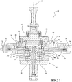
- Figure 1 illustrate a mold machine 10, such as a convention or standard mold machine, having a top core 12, also referred to head core, configured to form an upper crown portion of a piston; a main core 14 configured to form inner surfaces of the piston, and an outer panel mold 16 having a pair of diametrically opposite outer panels 18, 20 constructed in accordance with one aspect of the invention.
- the outer panel mold 16 provides the ability to readily convert the conventional mold machine 10 into a mold machine that is capable of molding complex undercut cooling galleries extending into an under surface of a piston head, thereby providing a quick and economical way in which to form pistons having complex-shaped outer cooling galleries, as desired.
- the undercut cooling galleries can be formed having any number of complex forms and shapes that are otherwise unattainable with a standard piston mold machine.
- the undercut cooling galleries due to the mechanism discussed hereafter with regard to the outer panels 18, 20, can extend radially upwardly and radially inwardly into outer faces of pin bosses of the piston, thereby forming diametrically opposite outer cooling galleries that converge toward one another, without concern of having to incorporate complex pivoting mechanisms, such as those discussed in the Related Art section above, or by having to use a complex dedicated piston mold machine specifically designed to make a single piston configuration.
- the outer panel mold 16 provides a quick and economical apparatus and method by which a conventional piston mold machine can be readily converted to mold pistons having complex outer cooling galleries extending, at least in part, into opposite outer faces of diametrically opposite pin bosses that diverge or flare outwardly toward free ends of the pin bosses, while at the same time allowing the conventional mold machine to be readily adapted to mold conventional pistons without undue expense.
- the top core 12 and main core 14 can be provided as standard components of the standard mold machine 10 to mold an upper crown and internal features of the piston, as desired.
- the top core 12 and main core 14 move vertically along a central longitudinal axis 22, corresponding to a central axis of the molded piston, between disengaged and engaged positions, as is known. When moved to their respective disengaged positions, the molded piston can be removed along a purely vertically upward direction from a mold cavity 24 without concern of interference with the mold components.
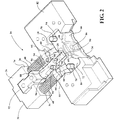
- the outer panel mold 16 includes a pair of gudgeon pin core drive blocks 26, referred to hereafter as pin core drive blocks and a pair of corresponding gudgeon pin cores 28, also referred to as pin bore mandrels or pin bore cores.
- Each pin core drive block 26 has one side 30 configured for operable attachment to a linear actuator (not shown) and an opposite side 32 configured for operable attachment to an end 34 of the pin bore core 28, shown as being connected via an dovetail-type joint connection, by way of example and without limitation.
- the pin core drive blocks 26 further include a pair of recessed bores or pockets 36 extending to a bottom surface or base 38 ( Figure 5 ).
- the bases 38 have reduced diameter through openings 40 extending therethrough for sliding receipt of a corresponding guide rod 42, wherein one end 43 of each guide rod 42 is operably fixed to a pin core guide block, also referred to as guide block 44, such as via pins 46 ( Figure 5 ), for example.
- the pockets 36 are configured for partial receipt of corresponding spring members 48 that abut the bottom surface 38 and extend outwardly from the pockets 36 into at least slightly compressed abutment with the guide block 44.
- the guide blocks 44 have opposite sides 52, 54 with a centrally located through bore 56 extending therethrough.
- the through bores 56 are sized for close sliding receipt of the pin bore cores 28 therethrough. Accordingly, upon movement of the pin core drive blocks 26, the pin bore cores 28 are free to slide through the through bores 56 between engaged and disengaged positions ( Figures 2 and 4 , respectively).
- the guide blocks 44 have a pair of driven members 58 and a pair of drive members 60.
- the driven members 58 are fixed to the guide blocks 44 and are selectively driven in response to axial movement of the pin bore cores 28 to cause conjoint movement of the outer panels 18, 20.
- the driven members 58 are shown as vertically extending pins that are fastened in fixed relation to the guide blocks 44, by way of example and without limitation.
- the drive members 60 are received in corresponding passages 62 in the guide blocks 44 that are sized for a close fit of the drive members 60 therein.
- the drive members 60 are fixed in the passages 62, such as via pins 64, by way of example and without limitation.
- the passages 62, and thus the drive members 60 extend at an angle oblique to the central longitudinal axis 22, shown as extending between about 30-60 degrees relative to the axis 22, though the angle can be provided outside of this range, as desired.
- the angle of inclination is oriented such that the drive members 60 extend upwardly and radially outwardly, such that they diverge from one another from lower ends toward upper ends.
- the outer panels 18, 20 having inner surfaces 66 contoured to form the desired shape of the pin boss outer faces. Further, the outer panels have upperwardly extending protrusions 68 shaped as negatives of the desired shape of the outer cooling galleries formed thereby.
- the protrusions 68 can extend axially upwardly and radially inwardly, such that the outer cooling galleries formed thereby extend axially upwardly and radially inwardly relative to the outer face of the pin boss depending immediately therefrom.
- a cooling gallery shaped in this configuration would require an elaborate pivoting mechanism or dedicated mold machine in order to remove the negative mold protrusion therefrom, however, the outer panels 18, 20, in accordance with one aspect of the invention, are able to be guided along a straight linear path via a pair of outer panel guide members 70, also referred to as guide pins.
- the guide pins 70 can be oriented to extend along any desired angle of inclination, such that the guide pins 70 can extend in oblique relation to the central longitudinal axis 22 ( Figure 6 ), such as extending axially upwardly and radially inwardly generally toward the central longitudinal axis 22, or in parallel or substantially parallel relation with the central longitudinal axis 22 ( Figure 6A ).
- the guide pins 70 extend through upper and lower faces 72, 74 via through passages 76 in a close sliding fit therein. Accordingly, the through passages 76 act as bushings through which the guide members 70 slide in response to the outer panels 18, 20 being driven by the drive members 60 of the pin core guide block 44.
- the guide pins 70 are captured at opposite ends by upper and lower plates 78, 80, while an intermediate plate 82 bounds or substantially bounds the outer panel mold 16.
- the outer panels 18, 20 further include through passages 84 sized for close sliding receipt of the drive members 60 therethrough, shown has being lined with bushings 85, by way of example.
- the through passages 84, and thus the drive members 60 extend in oblique relation to the central longitudinal axis 22, shown as extending axially upwardly and radially outwardly from the axis 22.
- the outer panels 18, 20 each include through openings 86 sized for close sliding receipt of the pin bore cores 28 as they move between their engaged and disengaged positions. When the pin bore cores 28 are in their fully engaged position, free ends of the pin bore cores 28 extend beyond the inner surfaces 66 to form gudgeon pin bores in the pin bosses during molding.
- the pin bore cores 28 have a central portion 88 extending between opposite ends 90, 92.
- the central portion 88 includes a recessed notch, shown as a pair of diametrically opposite recessed notches 94 extending axially between opposite shoulders 96, 98.
- the recessed notches 94 are contoured to receive the driven members 58 therein.
- the shoulders 96, 98 extend outwardly from the recessed notches 94 to abut the driven members 58 while closing and opening the outer panel mold 16, as discussed further below.
- the actuator (not shown) is actuated to push radially inwardly on the pin core drive blocks 26, which in turn causes conjoint radially inward movement of the pin bore cores 28.
- the spring members 48 having a sufficient spring force, cause the guide blocks 44 to move axially toward the outer panels 18, 20, which in turns causes the drive members 58, 60 to slide through the corresponding through passages 84, which in turn cause the outer panels 18, 20 to be driven vertically upwardly and radially inwardly along the guide members 70.
- top core 12 and main core 14 are moved into their respective closed positions, and then a suitable liquid piston mold material is introduced into the mold cavity 24.
- the mold material is allow to cool sufficiently, and then the mold is opened to allow the piston to be remove vertically upwardly from the mold cavity 24.
- the sequence of closing the mold components is essentially reversed. Accordingly, the actuator (not shown) is retracted to pull radially outwardly on the pin core drive blocks 26, which in turn causes conjoint radially outward movement of the pin bore cores 28.
- the spring members 48 having a sufficient spring force, maintain the guide blocks 44 in abutment with the outer panels 18, 20, and the recessed notches 94 move along the driven members 58 until the shoulders 98 engage the driven members 58.
- the shoulders 98 pull the driven members 58 axially outwardly, which in turn causes the ping core guide blocks 44 to move conjointly with the pin bore cores 28.
- the movement of the guide blocks 44 causes conjoint movement of the drive members 58, 60 which slide through the corresponding through passages 84, which in turn cause the outer panels 18, 20 to be driven vertically downwardly and radially outwardly along the guide members 70.
- the piston is free to be lifted vertically outwardly from the open mold cavity 24.
- a method of forming an undercut cooling gallery in a piston includes moving a pair of gudgeon core members 28 toward one another to an engaged position through respective gudgeon guide blocks 44 along a common gudgeon pin axis. Further, driving the gudgeon guide blocks 44 toward one another along the gudgeon pin axis while moving the gudgeon core members 28 toward their engaged position. Further yet, driving a pair of outer panels 18, 20 into a closed position in response to movement of the gudgeon guide blocks 44. Then, molding fluid piston material about upper portions 68 of the outer panels 18, 20 to form the undercut cooling gallery.
- Additional aspect of the method of forming the undercut can include the following: sliding the outer panels 18, 20 along members 60, 70 in response to movement of the gudgeon guide blocks 44; orienting the members 60, 70 to extend in oblique relation to the gudgeon pin axis; moving the gudgeon core members 28 relative to the gudgeon guide blocks 44 during at least a portion of the movement of the gudgeon core members 28 between their engaged and disengaged positions; moving the gudgeon guide blocks 44 conjointly with the gudgeon core members 28 during at least a portion of the movement of the gudgeon core members 28 between their engaged and disengaged positions; moving the outer panels 18, 20 toward the closed position along a converging linear path that is oblique to the gudgeon pin axis; and moving the outer panels 18, 20 toward the open position away from one another other along a diverging linear path that is oblique to the gudgeon pin axis.
- a method of constructing a piston includes providing a conventional mold machine and attaching an outer panel mold 16 to the mold machine.
- the outer panel mold 16 includes a pair of gudgeon core members 28, a pair of gudgeon guide blocks 44, and a pair of outer panels 18, 20. Further, moving the pair of gudgeon core members 28 toward one another through respective gudgeon guide blocks 44 along a common gudgeon pin axis to an engaged position. Then, driving the gudgeon guide blocks 44 toward one another along the gudgeon pin axis while the gudgeon core members 28 are moving toward their engaged position.
- Additional aspect of the method of constructing a piston can include the following: sliding the outer panels 18, 20 along members 60, 70 in response to movement of the gudgeon guide blocks 44; orienting the members 60, 70 to extend in oblique relation to the gudgeon pin axis; moving the gudgeon core members 28 relative to the gudgeon guide blocks 44 during at least a portion of the movement of the gudgeon core members 28 between their engaged and disengaged positions; moving the gudgeon guide blocks 44 conjointly with the gudgeon core members 28 during at least a portion of the movement of the gudgeon core members 28 between their engaged and disengaged positions; and moving the outer panels 18, 20 toward the closed position along a converging linear path that is oblique to the gudgeon pin axis; moving the outer panels 18, 20 toward the open position along a diverging linear path that is oblique to the gudgeon pin axis.
Landscapes
- Engineering & Computer Science (AREA)
- Mechanical Engineering (AREA)
- Moulds For Moulding Plastics Or The Like (AREA)
- Pistons, Piston Rings, And Cylinders (AREA)
- Molds, Cores, And Manufacturing Methods Thereof (AREA)
Description
- This invention relates generally to pistons and methods of construction thereof, and more particularly to piston molds and methods of construction therewith.
- It is known to construct a piston with an annular cooling gallery having an undercut located immediately radially inward of a piston ring belt. The undercut provides an overhanging portion of ring belt, which in turn presents complications in casting the piston. To avoid having to machine the undercut after casting, the mold cavity must include a projection or panel having a negative shape of the desired undercut configuration. However, in order to extract or remove the cast piston from the mold cavity, the panel must be removed completely from the undercut and the mold cavity. Because the depending ring belt is formed radially outward from the undercut, the panel cannot be simply moved radially outwardly in a purely horizontal direction from the undercut. To further complicate matters, pin bosses formed in the molding process that depend from the ring belt in laterally spaced relation from one another and flare laterally outwardly with respect to a central axis of the piston prevent the undercut forming panel from being moved downwardly in a purely vertical direction. Accordingly, to overcome this problem, many known mold assemblies include a panel that must be pivoted out of the mold cavity. However, the pivoting motion of the panel restricts the size of the available undercut that can be formed depending on the envelop dimensions of the mold cavity.
-
JP 2001 150097 A -
WO 2008/128153 A1 describes a piston mold assembly, in which cooling gallery mandrels are movable by rods. Finally, for forming the piston ofWO 2004/111419 A1 pivotable cores are provided. - A piston outer panel mold that is operably attachable to a conventional piston mold machine is provided. The outer panel mold has a pair of gudgeon core members and a pair of gudgeon guide blocks. The gudgeon core members are moveable toward and away from one another along a linear path that is substantially perpendicular to a longitudinal central axis of a piston between an engaged position and a disengaged position. Each of the gudgeon guide blocks having an opening receiving a separate one of the gudgeon core members for slideable movement therein. The outer panel mold further includes a pair of outer panels moveable into a closed position between the pair of gudgeon guide blocks to form an undercut cooling gallery of the piston. The outer panels are movable to an open position to allow extraction of the piston vertically along the longitudinal central axis. The outer panels are moveable in response to movement of the gudgeon guide blocks.
- In accordance with another aspect of providing the piston outer panel mold, the outer panels are configured as being moveable toward each other along a converging linear path toward the closed position and configured as being moveable away from each other along a diverging linear path to the open position.
- According to another aspect of the invention a method of foiming an undercut cooling gallery of a piston is provided. The method includes moving a pair of gudgeon core members toward one another to an engaged position through respective gudgeon guide blocks along a common gudgeon pin axis. Further, driving the gudgeon guide blocks toward one another along the gudgeon pin axis while moving the gudgeon core members toward their engaged position. Further yet, driving a pair of outer panels into a closed position in response to movement of the gudgeon core blocks. Then, molding fluid piston material about upper portions of the outer panels to form the undercut cooling gallery. Then, moving the gudgeon core members away from one another to a disengaged position along the gudgeon pin axis. Further yet, driving the gudgeon guide blocks away from one another along the gudgeon pin axis in response to movement of the gudgeon core members toward their disengaged position. Further, driving the outer panels into an open position in response to movement of the gudgeon core blocks.
- In accordance with the invention, the method of forming an undercut cooling gallery of a piston further includes moving the outer panels toward the closed position along a converging linear path that is oblique to the gudgeon pin axis and toward the open position away from one another other along a diverging linear path that is oblique to the gudgeon pin axis.
- In accordance with another aspect of the invention, a method of constructing a piston is provided. The method includes providing a conventional mold machine and attaching an outer panel mold to the mold machine. The outer panel mold includes a pair of gudgeon core members, a pair of gudgeon guide blocks, and a pair of outer panels. The method further includes moving the pair of gudgeon core members toward one another through respective gudgeon guide blocks along a common gudgeon pin axis to an engaged position. Further yet, the method includes driving the gudgeon guide blocks toward one another along the gudgeon pin axis while the gudgeon core members are moving toward their engaged position. Further yet, the method includes driving the pair of outer panels into a closed position in response to movement of the gudgeon core blocks. Then, molding fluid piston material within a mold cavity to form a piston body and about upper portions of the outer panels to form the undercut cooling gallery within the piston body. The method then includes moving the gudgeon core members away from one another to a disengaged position along the gudgeon pin axis. Further yet, driving the gudgeon guide blocks away from one another along the gudgeon pin axis in response to movement of the gudgeon core members toward their disengaged position. Further, driving the outer panels into an open position in response to movement of the gudgeon core blocks. Then, removing the piston body from the mold cavity.
- In accordance with another aspect of the method of constructing a piston, the method further includes moving the outer panels toward the closed position along a converging linear path that is oblique to the gudgeon pin axis and moving the outer panels toward the open position along a diverging linear path that is oblique to the gudgeon pin axis.
- These and other aspects, features and advantages of the invention will be readily appreciated when considered in connection with the following detailed description of the presently preferred embodiments and best mode, appended claims and accompanying drawings, wherein:
-
FIG. 1 is a cross-sectional view of a mold machine having an outer panel mold in accordance with one presently preferred embodiment of the invention; -
FIG. 2 is a perspective view of the outer panel mold ofFIG. 1 shown in an open position; -
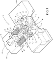
FIG. 3 is a view similar toFIG. 2 showing the outer panel mold in an intermediate position; -
FIG. 4 is a view similar toFIG. 2 showing the outer panel mold in a closed position; -
FIG. 5 is a split cross-sectional view taken through drive members of the outer panel mold showing the outer panel mold in a closed position on the left and in an open position on the right; -
Figure 6 is a split cross-sectional view taken through guide members of the outer panel mold showing the outer panel mold in a closed position on the left and in an open position on the right; and -
Figure 6A is a view similar toFigure 6 of an outer panel mold constructed in accordance with another aspect of the invention. - Referring in more detail to the drawings,
Figure 1 illustrate amold machine 10, such as a convention or standard mold machine, having atop core 12, also referred to head core, configured to form an upper crown portion of a piston; amain core 14 configured to form inner surfaces of the piston, and anouter panel mold 16 having a pair of diametrically oppositeouter panels outer panel mold 16 provides the ability to readily convert theconventional mold machine 10 into a mold machine that is capable of molding complex undercut cooling galleries extending into an under surface of a piston head, thereby providing a quick and economical way in which to form pistons having complex-shaped outer cooling galleries, as desired. The undercut cooling galleries can be formed having any number of complex forms and shapes that are otherwise unattainable with a standard piston mold machine. For example, the undercut cooling galleries, due to the mechanism discussed hereafter with regard to theouter panels outer panel mold 16 provides a quick and economical apparatus and method by which a conventional piston mold machine can be readily converted to mold pistons having complex outer cooling galleries extending, at least in part, into opposite outer faces of diametrically opposite pin bosses that diverge or flare outwardly toward free ends of the pin bosses, while at the same time allowing the conventional mold machine to be readily adapted to mold conventional pistons without undue expense. - The
top core 12 andmain core 14 can be provided as standard components of thestandard mold machine 10 to mold an upper crown and internal features of the piston, as desired. Thetop core 12 andmain core 14 move vertically along a centrallongitudinal axis 22, corresponding to a central axis of the molded piston, between disengaged and engaged positions, as is known. When moved to their respective disengaged positions, the molded piston can be removed along a purely vertically upward direction from amold cavity 24 without concern of interference with the mold components. This is due in large part to the ability to move thepanels outer panel mold 16 outwardly from their respective cooling galleries, either along an axis extending in oblique relation to the centrallongitudinal axis 22, or along an axis that is parallel or substantially parallel to the centrallongitudinal axis 22, depending on the configuration of theouter panel mold 16, discussed hereafter. - As best shown in
Figures 2-4 , theouter panel mold 16 includes a pair of gudgeon pin core drive blocks 26, referred to hereafter as pin core drive blocks and a pair of correspondinggudgeon pin cores 28, also referred to as pin bore mandrels or pin bore cores. Each pincore drive block 26 has oneside 30 configured for operable attachment to a linear actuator (not shown) and an opposite side 32 configured for operable attachment to anend 34 of the pin borecore 28, shown as being connected via an dovetail-type joint connection, by way of example and without limitation. The pin core drive blocks 26 further include a pair of recessed bores orpockets 36 extending to a bottom surface or base 38 (Figure 5 ). Thebases 38 have reduced diameter throughopenings 40 extending therethrough for sliding receipt of acorresponding guide rod 42, wherein oneend 43 of eachguide rod 42 is operably fixed to a pin core guide block, also referred to asguide block 44, such as via pins 46 (Figure 5 ), for example. Thepockets 36 are configured for partial receipt ofcorresponding spring members 48 that abut thebottom surface 38 and extend outwardly from thepockets 36 into at least slightly compressed abutment with theguide block 44. - The guide blocks 44 have
opposite sides bore 56 extending therethrough. The through bores 56 are sized for close sliding receipt of thepin bore cores 28 therethrough. Accordingly, upon movement of the pin core drive blocks 26, thepin bore cores 28 are free to slide through the through bores 56 between engaged and disengaged positions (Figures 2 and4 , respectively). - The guide blocks 44 have a pair of driven
members 58 and a pair ofdrive members 60. The drivenmembers 58 are fixed to the guide blocks 44 and are selectively driven in response to axial movement of thepin bore cores 28 to cause conjoint movement of theouter panels members 58 are shown as vertically extending pins that are fastened in fixed relation to the guide blocks 44, by way of example and without limitation. Thedrive members 60 are received in correspondingpassages 62 in the guide blocks 44 that are sized for a close fit of thedrive members 60 therein. Thedrive members 60 are fixed in thepassages 62, such as viapins 64, by way of example and without limitation. Thepassages 62, and thus thedrive members 60, extend at an angle oblique to the centrallongitudinal axis 22, shown as extending between about 30-60 degrees relative to theaxis 22, though the angle can be provided outside of this range, as desired. The angle of inclination is oriented such that thedrive members 60 extend upwardly and radially outwardly, such that they diverge from one another from lower ends toward upper ends. - The
outer panels inner surfaces 66 contoured to form the desired shape of the pin boss outer faces. Further, the outer panels have upperwardly extendingprotrusions 68 shaped as negatives of the desired shape of the outer cooling galleries formed thereby. Theprotrusions 68 can extend axially upwardly and radially inwardly, such that the outer cooling galleries formed thereby extend axially upwardly and radially inwardly relative to the outer face of the pin boss depending immediately therefrom. Ordinarily, a cooling gallery shaped in this configuration would require an elaborate pivoting mechanism or dedicated mold machine in order to remove the negative mold protrusion therefrom, however, theouter panels panel guide members 70, also referred to as guide pins. The guide pins 70 can be oriented to extend along any desired angle of inclination, such that the guide pins 70 can extend in oblique relation to the central longitudinal axis 22 (Figure 6 ), such as extending axially upwardly and radially inwardly generally toward the centrallongitudinal axis 22, or in parallel or substantially parallel relation with the central longitudinal axis 22 (Figure 6A ). The guide pins 70 extend through upper and lower faces 72, 74 via throughpassages 76 in a close sliding fit therein. Accordingly, the throughpassages 76 act as bushings through which theguide members 70 slide in response to theouter panels drive members 60 of the pincore guide block 44. The guide pins 70 are captured at opposite ends by upper andlower plates intermediate plate 82 bounds or substantially bounds theouter panel mold 16. - The
outer panels passages 84 sized for close sliding receipt of thedrive members 60 therethrough, shown has being lined withbushings 85, by way of example. The throughpassages 84, and thus thedrive members 60, extend in oblique relation to the centrallongitudinal axis 22, shown as extending axially upwardly and radially outwardly from theaxis 22. Further, theouter panels openings 86 sized for close sliding receipt of thepin bore cores 28 as they move between their engaged and disengaged positions. When thepin bore cores 28 are in their fully engaged position, free ends of thepin bore cores 28 extend beyond theinner surfaces 66 to form gudgeon pin bores in the pin bosses during molding. - The pin bore
cores 28 have acentral portion 88 extending between opposite ends 90, 92. Thecentral portion 88 includes a recessed notch, shown as a pair of diametrically opposite recessednotches 94 extending axially betweenopposite shoulders notches 94 are contoured to receive the drivenmembers 58 therein. Theshoulders notches 94 to abut the drivenmembers 58 while closing and opening theouter panel mold 16, as discussed further below. - In operation, with the
mold machine 10 in and open and disengaged position, the actuator (not shown) is actuated to push radially inwardly on the pin core drive blocks 26, which in turn causes conjoint radially inward movement of thepin bore cores 28. As thepin bore cores 28 advance coaxially toward one another, thespring members 48, having a sufficient spring force, cause the guide blocks 44 to move axially toward theouter panels drive members passages 84, which in turn cause theouter panels guide members 70. Upon theouter panels outer panels pin bore cores 28 continues as the drivenmembers 58 traverse the recessednotches 94. Then, upon the drivenmembers 58 engaging theshoulders 96, theouter panels - The
top core 12 andmain core 14 are moved into their respective closed positions, and then a suitable liquid piston mold material is introduced into themold cavity 24. The mold material is allow to cool sufficiently, and then the mold is opened to allow the piston to be remove vertically upwardly from themold cavity 24. - To initiate opening the
mold cavity 24, the sequence of closing the mold components is essentially reversed. Accordingly, the actuator (not shown) is retracted to pull radially outwardly on the pin core drive blocks 26, which in turn causes conjoint radially outward movement of thepin bore cores 28. As thepin bore cores 28 retract coaxially away from one another, thespring members 48, having a sufficient spring force, maintain the guide blocks 44 in abutment with theouter panels notches 94 move along the drivenmembers 58 until theshoulders 98 engage the drivenmembers 58. Upon theshoulders 98 engaging the drivenmembers 58, theshoulders 98 pull the drivenmembers 58 axially outwardly, which in turn causes the ping core guide blocks 44 to move conjointly with thepin bore cores 28. The movement of the guide blocks 44 causes conjoint movement of thedrive members passages 84, which in turn cause theouter panels guide members 70. Upon theouter panels top core 12 andmain core 14 being moved vertically to their corresponding retracted positions, the piston is free to be lifted vertically outwardly from theopen mold cavity 24. - In accordance with yet another aspect of the invention, a method of forming an undercut cooling gallery in a piston is provided. The method includes moving a pair of
gudgeon core members 28 toward one another to an engaged position through respective gudgeon guide blocks 44 along a common gudgeon pin axis. Further, driving the gudgeon guide blocks 44 toward one another along the gudgeon pin axis while moving thegudgeon core members 28 toward their engaged position. Further yet, driving a pair ofouter panels upper portions 68 of theouter panels gudgeon core members 28 away from one another to a disengaged position along the gudgeon pin axis. Further, driving the gudgeon guide blocks 44 away from one another along the gudgeon pin axis in response to movement of thegudgeon core members 28 toward their disengaged position. Then, driving theouter panels - Additional aspect of the method of forming the undercut can include the following: sliding the
outer panels members members gudgeon core members 28 relative to the gudgeon guide blocks 44 during at least a portion of the movement of thegudgeon core members 28 between their engaged and disengaged positions; moving the gudgeon guide blocks 44 conjointly with thegudgeon core members 28 during at least a portion of the movement of thegudgeon core members 28 between their engaged and disengaged positions; moving theouter panels outer panels - In accordance with yet another aspect of the invention, a method of constructing a piston is provided. The method includes providing a conventional mold machine and attaching an
outer panel mold 16 to the mold machine. Theouter panel mold 16 includes a pair ofgudgeon core members 28, a pair of gudgeon guide blocks 44, and a pair ofouter panels gudgeon core members 28 toward one another through respective gudgeon guide blocks 44 along a common gudgeon pin axis to an engaged position. Then, driving the gudgeon guide blocks 44 toward one another along the gudgeon pin axis while thegudgeon core members 28 are moving toward their engaged position. Further, driving the pair ofouter panels mold cavity 24 to form a piston body and aboutupper portions 68 of theouter panels gudgeon core members 28 away from one another to a disengaged position along the gudgeon pin axis. Then, driving the gudgeon guide blocks 44 away from one another along the gudgeon pin axis in response to movement of thegudgeon core members 28 toward their disengaged position. Further, driving theouter panels mold cavity 24. - Additional aspect of the method of constructing a piston can include the following: sliding the
outer panels members members gudgeon core members 28 relative to the gudgeon guide blocks 44 during at least a portion of the movement of thegudgeon core members 28 between their engaged and disengaged positions; moving the gudgeon guide blocks 44 conjointly with thegudgeon core members 28 during at least a portion of the movement of thegudgeon core members 28 between their engaged and disengaged positions; and moving theouter panels outer panels
Claims (14)
- A piston outer panel mold (16) that is operably attachable to a conventional piston mold machine (10), said outer panel piston mold comprising:a pair of gudgeon core members (28);a pair of gudgeon guide blocks (44) moveable toward and away from one another along a linear path that is substantially perpendicular to a central longitudinal axis of a piston between an engaged position and a disengaged position, each of said gudgeon guide blocks (44) having an opening (56) receiving a separate one of said gudgeon core members (28) for slideable movement therein; anda pair of outer panels (18, 20) moveable vertically into a closed position between said pair of gudgeon guide blocks (44) to form an undercut cooling gallery of the piston, said outer panels (18, 20) being movable vertically to an open position to allow extraction of the piston vertically along said central longitudinal axis, said outer panels (18, 20) being moveable between said open and closed positions in response to movement of said gudgeon guide blocks (44),wherein said pair of outer panels (18, 20) are moveable toward each other along a converging linear path toward said closed position and away from each other along a diverging linear path to said open position.
- The piston outer panel mold (16) of claim 1 further including at least one drive member (60) fixed to each of said gudgeon guide blocks (44), said outer panels (18, 20) having an opening (84) receiving said at least one drive member (60) for slideable movement therein.
- The piston outer panel mold (16) of claim 2 wherein each of said outer panels (18, 20) move along said at least one drive member (60) between their open and closed positions in response to movement of said at least one drive member (60).
- The piston outer panel mold (16) of claim 3 wherein said at least one drive member (60) extends in oblique relation to said central longitudinal axis.
- The piston outer panel mold (16) of claim 3 wherein said gudgeon guide blocks (44) move from their engaged position to their disengaged position in response to movement of said gudgeon core members (28).
- The piston outer panel mold (16) of claim 5 wherein each of said gudgeon guide blocks (44) have at least one driven member (58), said gudgeon core members (28) having a recessed notch (94) extending between opposite shoulders (96, 98).
- The piston outer panel mold (16) of claim 6 wherein said gudgeon core members (28) are moveable relative to said gudgeon guide blocks (44) when said driven member (58) is spaced from said shoulders.
- The piston outer panel mold (16) of claim 6 wherein said gudgeon guide blocks (44) move conjointly with said gudgeon core members (28) when said driven member (58) abuts one of said shoulders.
- The piston outer panel mold (16) of claim 2 wherein said pair of outer panels (18, 20) have upper and lower faces (72, 74) with at least one through opening (84) extending therethrough, said at least one through opening receiving a guide member (70) in a loose fit therein, and said outer panels (18, 20) sliding along said guide member in response to movement of said at least one drive member.
- The piston outer panel mold (16) of claim 9 wherein said guide member extends in oblique relation to said central longitudinal axis.
- The piston outer panel mold (16) of claim 10 wherein said guide member is inclined to extend axially upwardly and radially inwardly generally toward said central longitudinal axis.
- A method of forming an undercut cooling gallery in a piston, comprising:moving a pair of gudgeon core members (28) toward one another to an engaged position through respective gudgeon guide blocks (44) along a common gudgeon pin axis;driving the gudgeon guide blocks (44) toward one another along the gudgeon pin axis while moving the gudgeon core members (28) toward their engaged position;driving a pair of outer panels (18, 20) into a closed position in response to movement of the gudgeon guide blocks (44);molding fluid piston material about upper portions of the outer panels (18, 20) to form the undercut cooling gallery;moving the gudgeon core members (28) away from one another to a disengaged position along the gudgeon pin axis;driving the gudgeon guide blocks (44) away from one another along the gudgeon pin axis in response to movement of the gudgeon core members (28) toward their disengaged position; anddriving the outer panels (18, 20) into an open position in response to movement of the gudgeon guide blocks (44);wherein said pair of outer panels (18, 20) is moved towards each other along a converging linear path toward said closed position and away from each other along a diverging linear path to said open position.
- The method of claim 12 further including sliding the outer panels (18, 20) along members in response to movement of the gudgeon guide blocks (44).
- A method of constructing a piston, comprising:providing a conventional mold machine;attaching an outer panel mold (16) to the mold machine, the outer panel mold (16) having the pair of gudgeon core members (28), the pair of gudgeon guide blocks (44), and the pair of outer panels (18, 20);the method of claim 12;molding fluid piston material within a mold cavity to form a piston body; andremoving the piston body from the mold cavity.
Applications Claiming Priority (2)
| Application Number | Priority Date | Filing Date | Title |
|---|---|---|---|
| US13/544,978 US8459332B1 (en) | 2012-07-09 | 2012-07-09 | Piston outer panel mold and method of constructing a piston and forming an undercut cooling gallery of a piston therewith |
| PCT/US2013/049025 WO2014011440A2 (en) | 2012-07-09 | 2013-07-02 | Piston outer panel mold and method of constructing a piston and forming an undercut cooling gallery of a piston therewith |
Publications (2)
| Publication Number | Publication Date |
|---|---|
| EP2869952A2 EP2869952A2 (en) | 2015-05-13 |
| EP2869952B1 true EP2869952B1 (en) | 2019-05-22 |
Family
ID=48538268
Family Applications (1)
| Application Number | Title | Priority Date | Filing Date |
|---|---|---|---|
| EP13737950.9A Not-in-force EP2869952B1 (en) | 2012-07-09 | 2013-07-02 | Piston outer panel mold and method of constructing a piston and forming an undercut cooling gallery of a piston therewith |
Country Status (7)
| Country | Link |
|---|---|
| US (1) | US8459332B1 (en) |
| EP (1) | EP2869952B1 (en) |
| JP (1) | JP6199966B2 (en) |
| KR (1) | KR102055935B1 (en) |
| CN (1) | CN104619440B (en) |
| BR (1) | BR112015000425A2 (en) |
| WO (1) | WO2014011440A2 (en) |
Families Citing this family (3)
| Publication number | Priority date | Publication date | Assignee | Title |
|---|---|---|---|---|
| MX2021001785A (en) * | 2018-08-14 | 2021-07-15 | Anthony Cerniglia | Angle pin bushing and injection mold slide having same. |
| CN114367638B (en) * | 2021-11-19 | 2024-06-14 | 山东双港活塞股份有限公司 | Cooling method for rapidly cooling piston die |
| CN117066453B (en) * | 2023-10-16 | 2023-12-19 | 普洛特(烟台)汽车科技有限公司 | Casting forming treatment equipment for automobile brake disc |
Family Cites Families (25)
| Publication number | Priority date | Publication date | Assignee | Title |
|---|---|---|---|---|
| US2287524A (en) | 1941-02-26 | 1942-06-23 | Permold Co | Molding apparatus |
| US2286994A (en) | 1941-02-27 | 1942-06-16 | Permold Co | Molding apparatus |
| US2711568A (en) | 1951-09-07 | 1955-06-28 | Bohn Aluminium & Brass Corp | Permanent mold apparatus for casting hollow articles |
| US2676372A (en) | 1951-12-22 | 1954-04-27 | William M Venner | Piston molding core |
| US2789329A (en) | 1956-02-17 | 1957-04-23 | Sterling Aluminum Products Inc | Piston molding machine |
| US2948031A (en) | 1957-09-09 | 1960-08-09 | Thomas L Webb | Piston molding core |
| US4206799A (en) | 1978-12-11 | 1980-06-10 | Mcdonald John W | Oblique core locking mechanism for die casting machines |
| KR820001905B1 (en) | 1979-08-09 | 1982-10-19 | 요시다 다다오 | Continuous injection moulding machine |
| US4502660A (en) | 1983-11-21 | 1985-03-05 | Luther Leroy D | Mold including side walls with locking projections |
| JPS60231564A (en) * | 1984-05-02 | 1985-11-18 | Kyokuto Diecast Kk | Die for casting die cast product having middle recess in bore |
| JPS6174817A (en) * | 1984-09-19 | 1986-04-17 | Canon Inc | Undercut molding method |
| US5074352A (en) | 1987-11-28 | 1991-12-24 | Kabushiki Kaisha A. M. Technologies | Method for manufacturing ceramic reinforced piston |
| JPH02118652U (en) * | 1989-03-14 | 1990-09-25 | ||
| US5295804A (en) | 1992-07-27 | 1994-03-22 | Dinnan Timothy P | Female mold including decorating insert for differential pressure forming |
| US5295379A (en) | 1993-03-05 | 1994-03-22 | Italimpianti Of America, Inc. | Vertical piercer mill |
| KR950016982A (en) * | 1993-12-08 | 1995-07-20 | 전성원 | Undercut treatment method of die casting mold and its device |
| DE19922809A1 (en) | 1999-05-19 | 2000-11-23 | Mahle Gmbh | Casting process used in the production of pistons comprises producing recesses by cores that move on deformation |
| JP3400397B2 (en) | 1999-11-30 | 2003-04-28 | 本田金属技術株式会社 | Mold equipment |
| US20050056394A1 (en) * | 2002-01-31 | 2005-03-17 | Tht Presses Inc. | Semi-solid molding method and apparatus |
| DE10325917A1 (en) | 2003-06-07 | 2005-03-31 | Mahle Gmbh | Piston for an internal combustion engine and casting process for its production |
| JP4447391B2 (en) * | 2003-10-23 | 2010-04-07 | アイシン高丘株式会社 | Disc rotor manufacturing apparatus and manufacturing method |
| CN2834742Y (en) * | 2005-10-08 | 2006-11-08 | 山东滨州渤海活塞股份有限公司 | Piston blank with inner cooling channel being cast by liquid extrusion casting process |
| BRPI0810186A2 (en) * | 2007-04-13 | 2014-12-30 | Federal Mogul Powertrain Inc | MOLD ASSEMBLY FOR PISTON FORMING AND METHODS FOR FORMING AND PISTONING. |
| CN100500330C (en) * | 2007-06-15 | 2009-06-17 | 镇江中船设备有限公司 | Method for casting piston |
| CN202010764U (en) * | 2011-03-10 | 2011-10-19 | 山东滨州渤海活塞股份有限公司 | Middle core mold connecting mechanism of aluminum piston blank casting machine |
-
2012
- 2012-07-09 US US13/544,978 patent/US8459332B1/en active Active
-
2013
- 2013-07-02 EP EP13737950.9A patent/EP2869952B1/en not_active Not-in-force
- 2013-07-02 KR KR1020157002819A patent/KR102055935B1/en active IP Right Grant
- 2013-07-02 WO PCT/US2013/049025 patent/WO2014011440A2/en active Application Filing
- 2013-07-02 CN CN201380045748.7A patent/CN104619440B/en not_active Expired - Fee Related
- 2013-07-02 BR BR112015000425A patent/BR112015000425A2/en not_active Application Discontinuation
- 2013-07-02 JP JP2015521656A patent/JP6199966B2/en not_active Expired - Fee Related
Non-Patent Citations (1)
| Title |
|---|
| None * |
Also Published As
| Publication number | Publication date |
|---|---|
| JP2015523216A (en) | 2015-08-13 |
| US8459332B1 (en) | 2013-06-11 |
| WO2014011440A2 (en) | 2014-01-16 |
| CN104619440A (en) | 2015-05-13 |
| WO2014011440A3 (en) | 2014-04-03 |
| KR102055935B1 (en) | 2019-12-13 |
| CN104619440B (en) | 2017-02-15 |
| KR20150030749A (en) | 2015-03-20 |
| JP6199966B2 (en) | 2017-09-20 |
| BR112015000425A2 (en) | 2017-06-27 |
| EP2869952A2 (en) | 2015-05-13 |
Similar Documents
| Publication | Publication Date | Title |
|---|---|---|
| EP2139627B1 (en) | Piston mold assembly and method of constructing a piston therewith | |
| EP2869952B1 (en) | Piston outer panel mold and method of constructing a piston and forming an undercut cooling gallery of a piston therewith | |
| US7326045B2 (en) | System for releasing molded part from entrapping core rings | |
| CN106964755B (en) | Model casting automates wax injector | |
| CN105328873B (en) | A kind of angled core-pulling device | |
| JP2015044217A (en) | Core molding device | |
| KR20170058033A (en) | Die casting die having slide core | |
| US8997834B2 (en) | Method for producing of hollow die cast products | |
| CN110170619B (en) | Two-stage continuous automatic demoulding mechanism for casting quarto mould | |
| KR20170133660A (en) | Injection mold machine with a hydraulic cam slide assembly | |
| JP2015523216A5 (en) | ||
| CN108788026B (en) | Automatic demolding mechanism for complex sand core mold for engine casting | |
| CN208840458U (en) | A kind of complicated core mold automatic demoulding mechanism of engine casting | |
| CN109808110A (en) | A kind of plastics manufacturing equipment | |
| RU2476291C1 (en) | Method of making ice pistons and device to this end | |
| CN104875283B (en) | A kind of casting method for cylindrical part and its mould | |
| RU2579863C2 (en) | Device for casting piston for internal combustion engine and method of producing cast piston for internal combustion engine | |
| CN218836038U (en) | Die mould's different structure of loosing core of one-slide block | |
| CN219748775U (en) | Injection mold of comb body | |
| CN219748774U (en) | Injection mold of comb body | |
| CN108687328B (en) | Copper rotor does not have die casting die of loosing core | |
| RU2250152C2 (en) | Apparatus for making pistons of internal combustion engines | |
| CN215697864U (en) | Easy dismouting ejecting mechanism and die casting die | |
| CN112720973B (en) | Device for manufacturing annular groove in hole for plastic | |
| JP2001150097A (en) | Molding device |
Legal Events
| Date | Code | Title | Description |
|---|---|---|---|
| PUAI | Public reference made under article 153(3) epc to a published international application that has entered the european phase |
Free format text: ORIGINAL CODE: 0009012 |
|
| 17P | Request for examination filed |
Effective date: 20150204 |
|
| AK | Designated contracting states |
Kind code of ref document: A2 Designated state(s): AL AT BE BG CH CY CZ DE DK EE ES FI FR GB GR HR HU IE IS IT LI LT LU LV MC MK MT NL NO PL PT RO RS SE SI SK SM TR |
|
| AX | Request for extension of the european patent |
Extension state: BA ME |
|
| DAX | Request for extension of the european patent (deleted) | ||
| STAA | Information on the status of an ep patent application or granted ep patent |
Free format text: STATUS: EXAMINATION IS IN PROGRESS |
|
| 17Q | First examination report despatched |
Effective date: 20170915 |
|
| RAP1 | Party data changed (applicant data changed or rights of an application transferred) |
Owner name: FEDERAL-MOGUL LLC |
|
| GRAP | Despatch of communication of intention to grant a patent |
Free format text: ORIGINAL CODE: EPIDOSNIGR1 |
|
| STAA | Information on the status of an ep patent application or granted ep patent |
Free format text: STATUS: GRANT OF PATENT IS INTENDED |
|
| INTG | Intention to grant announced |
Effective date: 20190118 |
|
| RAP1 | Party data changed (applicant data changed or rights of an application transferred) |
Owner name: TENNECO INC. |
|
| GRAS | Grant fee paid |
Free format text: ORIGINAL CODE: EPIDOSNIGR3 |
|
| GRAA | (expected) grant |
Free format text: ORIGINAL CODE: 0009210 |
|
| STAA | Information on the status of an ep patent application or granted ep patent |
Free format text: STATUS: THE PATENT HAS BEEN GRANTED |
|
| AK | Designated contracting states |
Kind code of ref document: B1 Designated state(s): AL AT BE BG CH CY CZ DE DK EE ES FI FR GB GR HR HU IE IS IT LI LT LU LV MC MK MT NL NO PL PT RO RS SE SI SK SM TR |
|
| REG | Reference to a national code |
Ref country code: GB Ref legal event code: FG4D |
|
| REG | Reference to a national code |
Ref country code: CH Ref legal event code: EP |
|
| REG | Reference to a national code |
Ref country code: IE Ref legal event code: FG4D |
|
| REG | Reference to a national code |
Ref country code: DE Ref legal event code: R096 Ref document number: 602013055747 Country of ref document: DE |
|
| REG | Reference to a national code |
Ref country code: AT Ref legal event code: REF Ref document number: 1135491 Country of ref document: AT Kind code of ref document: T Effective date: 20190615 |
|
| PGFP | Annual fee paid to national office [announced via postgrant information from national office to epo] |
Ref country code: FR Payment date: 20190621 Year of fee payment: 7 |
|
| REG | Reference to a national code |
Ref country code: NL Ref legal event code: MP Effective date: 20190522 |
|
| REG | Reference to a national code |
Ref country code: LT Ref legal event code: MG4D |
|
| PG25 | Lapsed in a contracting state [announced via postgrant information from national office to epo] |
Ref country code: NO Free format text: LAPSE BECAUSE OF FAILURE TO SUBMIT A TRANSLATION OF THE DESCRIPTION OR TO PAY THE FEE WITHIN THE PRESCRIBED TIME-LIMIT Effective date: 20190822 Ref country code: FI Free format text: LAPSE BECAUSE OF FAILURE TO SUBMIT A TRANSLATION OF THE DESCRIPTION OR TO PAY THE FEE WITHIN THE PRESCRIBED TIME-LIMIT Effective date: 20190522 Ref country code: HR Free format text: LAPSE BECAUSE OF FAILURE TO SUBMIT A TRANSLATION OF THE DESCRIPTION OR TO PAY THE FEE WITHIN THE PRESCRIBED TIME-LIMIT Effective date: 20190522 Ref country code: LT Free format text: LAPSE BECAUSE OF FAILURE TO SUBMIT A TRANSLATION OF THE DESCRIPTION OR TO PAY THE FEE WITHIN THE PRESCRIBED TIME-LIMIT Effective date: 20190522 Ref country code: PT Free format text: LAPSE BECAUSE OF FAILURE TO SUBMIT A TRANSLATION OF THE DESCRIPTION OR TO PAY THE FEE WITHIN THE PRESCRIBED TIME-LIMIT Effective date: 20190922 Ref country code: ES Free format text: LAPSE BECAUSE OF FAILURE TO SUBMIT A TRANSLATION OF THE DESCRIPTION OR TO PAY THE FEE WITHIN THE PRESCRIBED TIME-LIMIT Effective date: 20190522 Ref country code: SE Free format text: LAPSE BECAUSE OF FAILURE TO SUBMIT A TRANSLATION OF THE DESCRIPTION OR TO PAY THE FEE WITHIN THE PRESCRIBED TIME-LIMIT Effective date: 20190522 Ref country code: NL Free format text: LAPSE BECAUSE OF FAILURE TO SUBMIT A TRANSLATION OF THE DESCRIPTION OR TO PAY THE FEE WITHIN THE PRESCRIBED TIME-LIMIT Effective date: 20190522 Ref country code: AL Free format text: LAPSE BECAUSE OF FAILURE TO SUBMIT A TRANSLATION OF THE DESCRIPTION OR TO PAY THE FEE WITHIN THE PRESCRIBED TIME-LIMIT Effective date: 20190522 |
|
| PGFP | Annual fee paid to national office [announced via postgrant information from national office to epo] |
Ref country code: DE Payment date: 20190617 Year of fee payment: 7 |
|
| PG25 | Lapsed in a contracting state [announced via postgrant information from national office to epo] |
Ref country code: BG Free format text: LAPSE BECAUSE OF FAILURE TO SUBMIT A TRANSLATION OF THE DESCRIPTION OR TO PAY THE FEE WITHIN THE PRESCRIBED TIME-LIMIT Effective date: 20190822 Ref country code: GR Free format text: LAPSE BECAUSE OF FAILURE TO SUBMIT A TRANSLATION OF THE DESCRIPTION OR TO PAY THE FEE WITHIN THE PRESCRIBED TIME-LIMIT Effective date: 20190823 Ref country code: LV Free format text: LAPSE BECAUSE OF FAILURE TO SUBMIT A TRANSLATION OF THE DESCRIPTION OR TO PAY THE FEE WITHIN THE PRESCRIBED TIME-LIMIT Effective date: 20190522 Ref country code: RS Free format text: LAPSE BECAUSE OF FAILURE TO SUBMIT A TRANSLATION OF THE DESCRIPTION OR TO PAY THE FEE WITHIN THE PRESCRIBED TIME-LIMIT Effective date: 20190522 |
|
| REG | Reference to a national code |
Ref country code: AT Ref legal event code: MK05 Ref document number: 1135491 Country of ref document: AT Kind code of ref document: T Effective date: 20190522 |
|
| PG25 | Lapsed in a contracting state [announced via postgrant information from national office to epo] |
Ref country code: SK Free format text: LAPSE BECAUSE OF FAILURE TO SUBMIT A TRANSLATION OF THE DESCRIPTION OR TO PAY THE FEE WITHIN THE PRESCRIBED TIME-LIMIT Effective date: 20190522 Ref country code: RO Free format text: LAPSE BECAUSE OF FAILURE TO SUBMIT A TRANSLATION OF THE DESCRIPTION OR TO PAY THE FEE WITHIN THE PRESCRIBED TIME-LIMIT Effective date: 20190522 Ref country code: AT Free format text: LAPSE BECAUSE OF FAILURE TO SUBMIT A TRANSLATION OF THE DESCRIPTION OR TO PAY THE FEE WITHIN THE PRESCRIBED TIME-LIMIT Effective date: 20190522 Ref country code: DK Free format text: LAPSE BECAUSE OF FAILURE TO SUBMIT A TRANSLATION OF THE DESCRIPTION OR TO PAY THE FEE WITHIN THE PRESCRIBED TIME-LIMIT Effective date: 20190522 Ref country code: CZ Free format text: LAPSE BECAUSE OF FAILURE TO SUBMIT A TRANSLATION OF THE DESCRIPTION OR TO PAY THE FEE WITHIN THE PRESCRIBED TIME-LIMIT Effective date: 20190522 Ref country code: EE Free format text: LAPSE BECAUSE OF FAILURE TO SUBMIT A TRANSLATION OF THE DESCRIPTION OR TO PAY THE FEE WITHIN THE PRESCRIBED TIME-LIMIT Effective date: 20190522 |
|
| REG | Reference to a national code |
Ref country code: DE Ref legal event code: R097 Ref document number: 602013055747 Country of ref document: DE |
|
| PG25 | Lapsed in a contracting state [announced via postgrant information from national office to epo] |
Ref country code: MC Free format text: LAPSE BECAUSE OF FAILURE TO SUBMIT A TRANSLATION OF THE DESCRIPTION OR TO PAY THE FEE WITHIN THE PRESCRIBED TIME-LIMIT Effective date: 20190522 Ref country code: SM Free format text: LAPSE BECAUSE OF FAILURE TO SUBMIT A TRANSLATION OF THE DESCRIPTION OR TO PAY THE FEE WITHIN THE PRESCRIBED TIME-LIMIT Effective date: 20190522 Ref country code: IT Free format text: LAPSE BECAUSE OF FAILURE TO SUBMIT A TRANSLATION OF THE DESCRIPTION OR TO PAY THE FEE WITHIN THE PRESCRIBED TIME-LIMIT Effective date: 20190522 |
|
| REG | Reference to a national code |
Ref country code: CH Ref legal event code: PL |
|
| PLBE | No opposition filed within time limit |
Free format text: ORIGINAL CODE: 0009261 |
|
| STAA | Information on the status of an ep patent application or granted ep patent |
Free format text: STATUS: NO OPPOSITION FILED WITHIN TIME LIMIT |
|
| PG25 | Lapsed in a contracting state [announced via postgrant information from national office to epo] |
Ref country code: TR Free format text: LAPSE BECAUSE OF FAILURE TO SUBMIT A TRANSLATION OF THE DESCRIPTION OR TO PAY THE FEE WITHIN THE PRESCRIBED TIME-LIMIT Effective date: 20190522 |
|
| REG | Reference to a national code |
Ref country code: BE Ref legal event code: MM Effective date: 20190731 |
|
| 26N | No opposition filed |
Effective date: 20200225 |
|
| GBPC | Gb: european patent ceased through non-payment of renewal fee |
Effective date: 20190822 |
|
| PG25 | Lapsed in a contracting state [announced via postgrant information from national office to epo] |
Ref country code: PL Free format text: LAPSE BECAUSE OF FAILURE TO SUBMIT A TRANSLATION OF THE DESCRIPTION OR TO PAY THE FEE WITHIN THE PRESCRIBED TIME-LIMIT Effective date: 20190522 |
|
| PG25 | Lapsed in a contracting state [announced via postgrant information from national office to epo] |
Ref country code: BE Free format text: LAPSE BECAUSE OF NON-PAYMENT OF DUE FEES Effective date: 20190731 Ref country code: CH Free format text: LAPSE BECAUSE OF NON-PAYMENT OF DUE FEES Effective date: 20190731 Ref country code: LU Free format text: LAPSE BECAUSE OF NON-PAYMENT OF DUE FEES Effective date: 20190702 Ref country code: LI Free format text: LAPSE BECAUSE OF NON-PAYMENT OF DUE FEES Effective date: 20190731 Ref country code: SI Free format text: LAPSE BECAUSE OF FAILURE TO SUBMIT A TRANSLATION OF THE DESCRIPTION OR TO PAY THE FEE WITHIN THE PRESCRIBED TIME-LIMIT Effective date: 20190522 |
|
| PG25 | Lapsed in a contracting state [announced via postgrant information from national office to epo] |
Ref country code: IE Free format text: LAPSE BECAUSE OF NON-PAYMENT OF DUE FEES Effective date: 20190702 |
|
| PG25 | Lapsed in a contracting state [announced via postgrant information from national office to epo] |
Ref country code: GB Free format text: LAPSE BECAUSE OF NON-PAYMENT OF DUE FEES Effective date: 20190822 |
|
| REG | Reference to a national code |
Ref country code: DE Ref legal event code: R119 Ref document number: 602013055747 Country of ref document: DE |
|
| PG25 | Lapsed in a contracting state [announced via postgrant information from national office to epo] |
Ref country code: FR Free format text: LAPSE BECAUSE OF NON-PAYMENT OF DUE FEES Effective date: 20200731 |
|
| PG25 | Lapsed in a contracting state [announced via postgrant information from national office to epo] |
Ref country code: CY Free format text: LAPSE BECAUSE OF FAILURE TO SUBMIT A TRANSLATION OF THE DESCRIPTION OR TO PAY THE FEE WITHIN THE PRESCRIBED TIME-LIMIT Effective date: 20190522 Ref country code: DE Free format text: LAPSE BECAUSE OF NON-PAYMENT OF DUE FEES Effective date: 20210202 |
|
| PG25 | Lapsed in a contracting state [announced via postgrant information from national office to epo] |
Ref country code: IS Free format text: LAPSE BECAUSE OF FAILURE TO SUBMIT A TRANSLATION OF THE DESCRIPTION OR TO PAY THE FEE WITHIN THE PRESCRIBED TIME-LIMIT Effective date: 20190922 |
|
| PG25 | Lapsed in a contracting state [announced via postgrant information from national office to epo] |
Ref country code: HU Free format text: LAPSE BECAUSE OF FAILURE TO SUBMIT A TRANSLATION OF THE DESCRIPTION OR TO PAY THE FEE WITHIN THE PRESCRIBED TIME-LIMIT; INVALID AB INITIO Effective date: 20130702 Ref country code: MT Free format text: LAPSE BECAUSE OF FAILURE TO SUBMIT A TRANSLATION OF THE DESCRIPTION OR TO PAY THE FEE WITHIN THE PRESCRIBED TIME-LIMIT Effective date: 20190522 |
|
| PG25 | Lapsed in a contracting state [announced via postgrant information from national office to epo] |
Ref country code: MK Free format text: LAPSE BECAUSE OF FAILURE TO SUBMIT A TRANSLATION OF THE DESCRIPTION OR TO PAY THE FEE WITHIN THE PRESCRIBED TIME-LIMIT Effective date: 20190522 |