KR102023233B1 - Space filling devices - Google Patents
Space filling devices Download PDFInfo
- Publication number
- KR102023233B1 KR102023233B1 KR1020157015570A KR20157015570A KR102023233B1 KR 102023233 B1 KR102023233 B1 KR 102023233B1 KR 1020157015570 A KR1020157015570 A KR 1020157015570A KR 20157015570 A KR20157015570 A KR 20157015570A KR 102023233 B1 KR102023233 B1 KR 102023233B1
- Authority
- KR
- South Korea
- Prior art keywords
- anchor
- delete delete
- frame
- proximal
- distal
- Prior art date
Links
Images


Classifications
-
- A—HUMAN NECESSITIES
- A61—MEDICAL OR VETERINARY SCIENCE; HYGIENE
- A61B—DIAGNOSIS; SURGERY; IDENTIFICATION
- A61B17/00—Surgical instruments, devices or methods, e.g. tourniquets
- A61B17/12—Surgical instruments, devices or methods, e.g. tourniquets for ligaturing or otherwise compressing tubular parts of the body, e.g. blood vessels, umbilical cord
- A61B17/12022—Occluding by internal devices, e.g. balloons or releasable wires
- A61B17/12099—Occluding by internal devices, e.g. balloons or releasable wires characterised by the location of the occluder
- A61B17/12122—Occluding by internal devices, e.g. balloons or releasable wires characterised by the location of the occluder within the heart
-
- A—HUMAN NECESSITIES
- A61—MEDICAL OR VETERINARY SCIENCE; HYGIENE
- A61B—DIAGNOSIS; SURGERY; IDENTIFICATION
- A61B17/00—Surgical instruments, devices or methods, e.g. tourniquets
- A61B17/0057—Implements for plugging an opening in the wall of a hollow or tubular organ, e.g. for sealing a vessel puncture or closing a cardiac septal defect
-
- A—HUMAN NECESSITIES
- A61—MEDICAL OR VETERINARY SCIENCE; HYGIENE
- A61B—DIAGNOSIS; SURGERY; IDENTIFICATION
- A61B17/00—Surgical instruments, devices or methods, e.g. tourniquets
- A61B17/12—Surgical instruments, devices or methods, e.g. tourniquets for ligaturing or otherwise compressing tubular parts of the body, e.g. blood vessels, umbilical cord
- A61B17/12022—Occluding by internal devices, e.g. balloons or releasable wires
- A61B17/12131—Occluding by internal devices, e.g. balloons or releasable wires characterised by the type of occluding device
- A61B17/12168—Occluding by internal devices, e.g. balloons or releasable wires characterised by the type of occluding device having a mesh structure
- A61B17/12172—Occluding by internal devices, e.g. balloons or releasable wires characterised by the type of occluding device having a mesh structure having a pre-set deployed three-dimensional shape
-
- A—HUMAN NECESSITIES
- A61—MEDICAL OR VETERINARY SCIENCE; HYGIENE
- A61B—DIAGNOSIS; SURGERY; IDENTIFICATION
- A61B17/00—Surgical instruments, devices or methods, e.g. tourniquets
- A61B17/12—Surgical instruments, devices or methods, e.g. tourniquets for ligaturing or otherwise compressing tubular parts of the body, e.g. blood vessels, umbilical cord
- A61B17/12022—Occluding by internal devices, e.g. balloons or releasable wires
- A61B17/12131—Occluding by internal devices, e.g. balloons or releasable wires characterised by the type of occluding device
- A61B17/12168—Occluding by internal devices, e.g. balloons or releasable wires characterised by the type of occluding device having a mesh structure
- A61B17/12177—Occluding by internal devices, e.g. balloons or releasable wires characterised by the type of occluding device having a mesh structure comprising additional materials, e.g. thrombogenic, having filaments, having fibers or being coated
-
- A—HUMAN NECESSITIES
- A61—MEDICAL OR VETERINARY SCIENCE; HYGIENE
- A61B—DIAGNOSIS; SURGERY; IDENTIFICATION
- A61B17/00—Surgical instruments, devices or methods, e.g. tourniquets
- A61B2017/00526—Methods of manufacturing
-
- A—HUMAN NECESSITIES
- A61—MEDICAL OR VETERINARY SCIENCE; HYGIENE
- A61B—DIAGNOSIS; SURGERY; IDENTIFICATION
- A61B17/00—Surgical instruments, devices or methods, e.g. tourniquets
- A61B17/0057—Implements for plugging an opening in the wall of a hollow or tubular organ, e.g. for sealing a vessel puncture or closing a cardiac septal defect
- A61B2017/00575—Implements for plugging an opening in the wall of a hollow or tubular organ, e.g. for sealing a vessel puncture or closing a cardiac septal defect for closure at remote site, e.g. closing atrial septum defects
- A61B2017/00579—Barbed implements
-
- A—HUMAN NECESSITIES
- A61—MEDICAL OR VETERINARY SCIENCE; HYGIENE
- A61B—DIAGNOSIS; SURGERY; IDENTIFICATION
- A61B17/00—Surgical instruments, devices or methods, e.g. tourniquets
- A61B17/0057—Implements for plugging an opening in the wall of a hollow or tubular organ, e.g. for sealing a vessel puncture or closing a cardiac septal defect
- A61B2017/00575—Implements for plugging an opening in the wall of a hollow or tubular organ, e.g. for sealing a vessel puncture or closing a cardiac septal defect for closure at remote site, e.g. closing atrial septum defects
- A61B2017/00592—Elastic or resilient implements
-
- A—HUMAN NECESSITIES
- A61—MEDICAL OR VETERINARY SCIENCE; HYGIENE
- A61B—DIAGNOSIS; SURGERY; IDENTIFICATION
- A61B17/00—Surgical instruments, devices or methods, e.g. tourniquets
- A61B17/0057—Implements for plugging an opening in the wall of a hollow or tubular organ, e.g. for sealing a vessel puncture or closing a cardiac septal defect
- A61B2017/00575—Implements for plugging an opening in the wall of a hollow or tubular organ, e.g. for sealing a vessel puncture or closing a cardiac septal defect for closure at remote site, e.g. closing atrial septum defects
- A61B2017/00597—Implements comprising a membrane
-
- A—HUMAN NECESSITIES
- A61—MEDICAL OR VETERINARY SCIENCE; HYGIENE
- A61F—FILTERS IMPLANTABLE INTO BLOOD VESSELS; PROSTHESES; DEVICES PROVIDING PATENCY TO, OR PREVENTING COLLAPSING OF, TUBULAR STRUCTURES OF THE BODY, e.g. STENTS; ORTHOPAEDIC, NURSING OR CONTRACEPTIVE DEVICES; FOMENTATION; TREATMENT OR PROTECTION OF EYES OR EARS; BANDAGES, DRESSINGS OR ABSORBENT PADS; FIRST-AID KITS
- A61F2/00—Filters implantable into blood vessels; Prostheses, i.e. artificial substitutes or replacements for parts of the body; Appliances for connecting them with the body; Devices providing patency to, or preventing collapsing of, tubular structures of the body, e.g. stents
- A61F2/01—Filters implantable into blood vessels
Abstract
기기(100)는 다수의 세장 부재(102), 폐색 구성 요소(112), 및 지지 구성 요소(114)를 포함한다. 폐색 구성 요소는 각각 각 세장 부재의 제1 부분에 의해 한정되는 다수의 제1 기구를 포함한다. 지지 구성 요소는 각각 가 세장 부재의 제2 부분에 의해 한정되는 다수의 제2 기구를 포함한다. 제1 종단 요소(108)는 다수의 세장 부재의 근위 단부에 의해 한정되고, 기기의 근위단 가까이에 위치하며, 제2 종단 요소(106)는 다수의 세장 부재의 원위 단부에 의해 한정되고, 기기의 원위단 가까이에 위치한다. 1 이상의 앵커 요소(110)는 프레임 부착부와 앵커부를 포함하고, 프레임 부착부는 세장 부재를 둘러싸는 고정 세장 요소의 제1 부분을 포함하며, 앵커부는 앵커 기구를 포함한다.The device 100 includes a plurality of elongate members 102, occlusion components 112, and support components 114. The occlusion component includes a plurality of first mechanisms, each defined by a first portion of each elongate member. The support component includes a plurality of second mechanisms, each of which is defined by a second portion of the elongate member. The first end element 108 is defined by the proximal end of the plurality of elongate members, located near the proximal end of the device, and the second end element 106 is defined by the distal end of the plurality of elongate members, It is located near the distal end of. The at least one anchor element 110 includes a frame attachment and an anchor, the frame attachment including a first portion of the fixed elongate element surrounding the elongate member, wherein the anchor includes an anchor mechanism.
Description
본 개시 내용은 환자 내에서 개구(aperture), 도관, 또는 구조를 폐색하는데 사용될 수 있는 이식가능한 의료 기기에 관한 것이다.The present disclosure relates to implantable medical devices that can be used to occlude an aperture, conduit, or structure in a patient.
심방 부속기와 같은 심장 기구(cardiac feature)는 흔히 심장 혈류 장해의 한 원인으로 되며, 이는 다수의 심장 관련 병리와 관련된다. 예를 들어, 좌심방 부속기(LAA, left atrial appendage) 내 혈류 장해가 원인이 되고, 심방 세동과 관련된 합병증은 색전성 뇌졸중의 한 원인이 될 수 있다. LAA는 심장의 좌심방 전회측 벽에서 연장되는 근육 주머니이며, 좌심방을 위한 저장소로서 역할을 한다. 정상 심장 주기 동안, LAA는 좌심방과 함께 수축하여 혈액을 LAA로부터 펌핑하고, 이는 일반적으로 혈액이 LAA 내에 정체하는 것을 방지한다. 그러나 부정맥(예, 심방 세동)을 특징으로 한 심장 주기 동안, LAA는 흔히 충분히 수축하지 못하며, 이는 혈액이 LAA 내에 정체하게 할 수 있다. LAA 내 정체 혈액은 응고되어 혈전을 형성하기 쉬우며, 이는 LAA로부터 제자리를 벗어나 결국 색전성 뇌졸중을 초래할 수 있다.Cardiac features, such as atrial appendages, are often a cause of cardiac blood flow disorders, which are associated with many cardiac-related pathologies. For example, blood flow disorders in the left atrial appendage (LAA) are caused, and complications associated with atrial fibrillation can be a cause of embolic stroke. LAA is a muscle sac that extends from the anterior wall of the left atrium of the heart and serves as a reservoir for the left atrium. During a normal cardiac cycle, the LAA contracts with the left atrium to pump blood from the LAA, which generally prevents blood from stagnating in the LAA. However, during cardiac cycles characterized by arrhythmias (eg, atrial fibrillation), LAAs often do not contract sufficiently, which can cause blood to stagnate within the LAA. Stagnant blood in the LAA tends to coagulate and form a thrombus, which can leave the LAA in place and eventually result in an embolic stroke.
제1 일반 양태에서, 환자의 신체에서 개구를 폐색하기 위한 기기는 다수의 세장 부재(elongate member)를 포함한다. 이 기기는 또한 다수의 세장 부재 중 각 세장 부재의 제1 부분에 의해 각각 한정되는 다수의 제1 기구(feature)를 포함하는 폐색 구성 요소를 포함하며, 여기서 제1 기구는 기기의 일반적으로 근위 영역(proximal region)에 위치한다. 기기는 추가로 다수의 세장 부재 중 각 세장 부재의 제2 부분에 의해 각각 한정되는 다수의 제2 기구를 포함하는 지지 구성 요소를 포함하며, 여기서 제2 기구는 기기의 일반적으로 원위 영역에 위치한다. 기기는 추가로 다수의 세장 부재의 근위 단부에 의해 한정되고, 기기의 근위단 가까이에 위치하는 제1 종단 요소, 및 다수의 세장 부재의 원위 단부에 의해 한정되고, 기기의 원위단 가까이에 위치하는 제2 종단 요소를 포함한다. 다수의 세장 요소 증 각 세장 요소는 제1 기구 중 하나 및 제2 기구 중 하나를 한정하며, 특정 세장 요소에 의해 한정되는 제2 기구는 기기의 근위단에서 볼 때 특정 세장 요소에 의해 한정되는 제1 기구에 관해 각도 방향에서 일반적으로 오프셋(offset)된다.In a first general aspect, the device for occluding the opening in the patient's body includes a plurality of elongate members. The device also includes a occlusion component that includes a plurality of first features each defined by a first portion of each of the elongated members, wherein the first device is a generally proximal region of the device. It is located in the (proximal region). The device further includes a support component comprising a plurality of second mechanisms, each of which is defined by a second portion of each of the elongated members, wherein the second mechanism is located in a generally distal region of the device. . The device is further defined by the proximal end of the plurality of elongate members, defined by a first termination element located near the proximal end of the device, and by the distal end of the plurality of elongate members, located near the distal end of the device. And a second termination element. Multiple elongate element enhancement Each elongate element defines one of the first mechanism and one of the second mechanisms, and the second mechanism, defined by the particular elongated element, is defined by the particular elongated element as viewed from the proximal end of the device. It is generally offset in the angular direction with respect to one instrument.
다양한 실시에서, 특정 세장 요소에 의해 한정되는 제2 기구는 기기의 근위단에서 볼 때 특정 세장 요소에 의해 한정되는 제1 기구에 관해 시계 방향의 각도 방향으로 오프셋될 수 있다. 특정 세장 요소에 의해 한정되는 제2 기구는 기기의 근위단에서 볼 때 특정 세장 요소에 의해 한정되는 제1 기구에 관해 반시계 방향의 각도 방향으로 오프셋될 수 있다. 특정 세장 요소에 의해 한정되는 제2 기구는 다수의 세장 요소 중 또 다른 세장 요소에 의해 한정되는 제1 기구와 일반적으로 길이로 정렬될 수 있다. 또 다른 세장 요소에 의해 한정되는 제1 기구는 특정 세장 요소에 의해 한정되는 제1 기구에 인접할 수 있다. 다수의 세장 요소 중 각 세장 요소에 대해, 세장 요소에 의해 한정되는 상응하는 제2 기구는 기기의 근위단에서 볼 때 세장 요소에 의해 한정되는 상응하는 제1 기구에 관해 각도 방향에서 일반적으로 오프셋될 수 있다. 권선(winding) 방향은 하나 이상의 세장 부재에 의해 한정되는 상응하는 제1 및 제2 기구 사이에 다수의 세장 부재 중 하나 이상의 세장 부재에 대해 반전될 수 있다. 권선 방향은 시계 방향에서 반시계 방향으로, 또는 반시계 방향에서 시계 방향으로 반전될 수 있다. 제1 및 제2 종단 요소는 아일릿(eyelet)일 수 있다. 기기는 또한 기기의 적어도 일부를 덮는 막질 피복(covering)을 포함할 수 있다. 막질 피복은 폐색 구성 요소와 지지 구성 요소를 덮을 수 있다. 막질 피복은 제1 종단 요소와 제2 종단 요소를 덮을 수 있다. 다수의 세장 부재 중 각 세장 부재는 와이어(wire), 예컨대 니티놀(Nitinol) 와이어일 수 있다. 기기는 금속 튜브를 절단함으로써 형성될 수 있다. 다수의 세장 부재 중 각 세장 부재는 튜브의 일부일 수 있다. 기기는 추가로 1 이상의 앵커 요소(anchor element)를 포함할 수 있다. 1 이상의 앵커 요소는 프레임 부착부와 앵커부를 포함할 수 있으며, 여기서 프레임 부착부는 다수의 세장 부재 중 한 세장 부재를 수회 둘러싸는 고정 세장 요소의 제1 부분을 포함하며, 앵커부는 고정 세장 요소의 제2 부분에서 신체 조직을 맞물리기 위한 앵커 기구를 포함한다. 1 이상의 앵커 요소는 다수의 세장 요소 중 한 세장 요소의 부분에 의해 형성되는 앵커부를 포함할 수 있다.In various implementations, the second mechanism defined by the particular elongate element may be offset in the clockwise angular direction relative to the first mechanism defined by the particular elongate element when viewed from the proximal end of the device. The second mechanism, defined by the particular elongate element, may be offset in an angular direction counterclockwise relative to the first mechanism, defined by the particular elongate element, when viewed from the proximal end of the device. The second mechanism defined by the particular elongate element may be generally length aligned with the first mechanism defined by another elongate element of the plurality of elongate elements. The first mechanism defined by another elongate element may be adjacent to the first mechanism defined by a particular elongate element. For each elongated element of the plurality of elongated elements, the corresponding second mechanism defined by the elongated element will generally be offset in the angular direction with respect to the corresponding first mechanism defined by the elongated element when viewed from the proximal end of the device. Can be. The winding direction may be reversed for one or more of the plurality of elongate members between corresponding first and second mechanisms defined by the one or more elongate members. The winding direction can be reversed clockwise in a clockwise direction or counterclockwise in a clockwise direction. The first and second termination elements may be eyelets. The device may also include a membrane covering covering at least a portion of the device. The membrane coating can cover the occlusion component and the support component. The membrane sheath may cover the first termination element and the second termination element. Each of the plurality of elongate members may be a wire, such as Nitinol wire. The device can be formed by cutting a metal tube. Each of the plurality of elongate members may be part of a tube. The device may further comprise one or more anchor elements. The one or more anchor elements may comprise a frame attachment and an anchor, wherein the frame attachment includes a first portion of the fixed elongate element that surrounds one of the plurality of elongate members several times, wherein the anchor portion is formed of the fixed elongate element. Anchor mechanism for engaging body tissue in two parts. The one or more anchor elements may comprise anchor portions formed by portions of one of the plurality of elongate elements.
제2 일반 양태에서, 환자의 신체에서 개구를 폐색하기 위한 기기는 다수의 세장 부재, 및 다수의 세장 부재 중 각 세장 부재의 제1 부분에 의해 각각 한정되는 다수의 제1 기구를 포함하는 폐색 구성 요소를 포함하며, 여기서 제1 기구는 기기의 일반적으로 근위 영역에 위치한다. 기기는 또한 다수의 세장 부재 중 각 세장 부재의 제2 부분에 의해 각각 한정되는 다수의 제2 기구를 포함하는 지지 구성 요소를 포함하며, 여기서 제2 기구는 기기의 일반적으로 원위 영역에 위치한다. 기기는 추가로 다수의 세장 부재의 근위 단부에 의해 한정되고, 기기의 근위단 가까이에 위치하는 제1 종단 요소, 및 다수의 세장 부재의 원위 단부에 의해 한정되고, 기기의 원위단 가까이에 위치하는 제2 종단 요소를 포함한다. 각각 다수의 세장 요소 중 특정 세장 요소에 의해 한정되는, 상응하는 제1 기구와 상응하는 제2 기구 사이에, 특정 세장 요소의 권선 방향은 반전된다.In a second general aspect, an apparatus for occluding an opening in a patient's body includes a plurality of elongate members and a plurality of first mechanisms each defined by a first portion of each elongated member of the plurality of elongated members. An element, wherein the first instrument is located in a generally proximal region of the device. The device also includes a support component that includes a plurality of second mechanisms, each of which is defined by a second portion of each of the elongated members, wherein the second mechanism is located in a generally distal region of the device. The device is further defined by the proximal end of the plurality of elongate members, defined by a first termination element located near the proximal end of the device, and by the distal end of the plurality of elongate members, located near the distal end of the device. And a second termination element. The winding direction of the particular elongate element is reversed between the corresponding first mechanism and the corresponding second mechanism, each defined by the particular elongate element of the plurality of elongate elements.
제3 일반 양태에서, 환자의 신체에서 개구를 폐색하기 위한 기기는 다수의 세장 부재, 및 다수의 세장 부재 중 각 세장 부재의 제1 부분에 의해 각각 한정되는 다수의 제1 기구를 포함하는 폐색 구성 요소를 포함하며, 여기서 제1 기구는 기기의 일반적으로 근위 영역에 위치한다. 기기는 또한 다수의 세장 부재 중 각 세장 부재의 제2 부분에 의해 각각 한정되는 다수의 제2 기구를 포함하며, 여기서 제2 기구는 기기의 일반적으로 원위 영역에 위치한다. 기기는 추가로 다수의 세장 부재의 근위 단부에 의해 그리고 다수의 세장 부재의 원위 단부에 의해 한정되는 종단 요소를 포함한다.In a third general aspect, an apparatus for occluding an opening in a patient's body includes a plurality of elongated members and a plurality of first mechanisms, each defined by a first portion of each elongated member of the plurality of elongated members. An element, wherein the first instrument is located in a generally proximal region of the device. The device also includes a plurality of second mechanisms, each defined by a second portion of each of the plurality of elongate members, wherein the second mechanism is located in a generally distal region of the device. The device further includes a termination element defined by the proximal end of the plurality of elongate members and by the distal end of the plurality of elongate members.
제4 일반 양태에서, 환자의 신체에서 개구를 폐색하기 위한 기기는 다수의 세장 부재, 및 다수의 세장 부재 중 각 세장 부재의 제1 부분에 의해 각각 한정되는 다수의 제1 기구를 포함하는 폐색 구성 요소를 포함하며, 여기서 제1 기구는 기기의 일반적으로 근위 영역에 위치한다. 기기는 또한 다수의 세장 부재 중 각 세장 부재의 제2 부분에 의해 각각 한정되는 다수의 제2 기구를 포함하는 지지 구성 요소를 포함하며, 여기서 제2 기구는 기기의 일반적으로 원위 영역에 위치한다. 기기는 추가로 다수의 세장 부재의 근위 단부에 의해 한정되고, 기기의 근위단 가까이에 위치하는 제1 종단 요소를 포함한다. 기기는 추가로 다수의 세장 부재의 원위 단부에 의해 한정되고, 기기의 원위단 가까이에 위치하는 제2 종단 요소를 포함한다. 다수의 세장 요소 중 각 세장 요소는 제1 기구의 하나 및 제2 기구의 하나를 한정하고, 특정 세장 요소에 의해 한정되는 제2 기구는 특정 세장 요소에 의해 한정되는 제1 기구와 기기의 종 방향 치수(longitudinal dimension)로 일반적으로 정렬된다.In a fourth general aspect, an apparatus for occluding an opening in a patient's body includes a plurality of elongated members and a plurality of first mechanisms each defined by a first portion of each elongated member of the plurality of elongated members. An element, wherein the first instrument is located in a generally proximal region of the device. The device also includes a support component that includes a plurality of second mechanisms, each of which is defined by a second portion of each of the elongated members, wherein the second mechanism is located in a generally distal region of the device. The device is further defined by the proximal end of the plurality of elongate members and includes a first termination element located near the proximal end of the device. The device is further defined by the distal end of the plurality of elongate members and includes a second termination element located near the distal end of the device. Each of the plurality of elongate elements defines one of the first mechanism and one of the second mechanisms, and the second mechanism defined by the particular elongate element is the longitudinal direction of the first appliance and the appliance defined by the particular elongate element. It is generally aligned by longitudinal dimension.
제5 일반 양태에서, 환자의 신체에서 개구를 폐색하기 위한 기기는 다수의 세장 부재, 및 다수의 세장 부재 중 각 세장 부재의 제1 부분에 의해 각각 한정되는 다수의 제1 기구를 포함하는 폐색 구성 요소를 포함하며, 여기서 제1 기구는 기기의 일반적으로 근위 영역에 위치한다. 기기는 또한 다수의 세장 부재 중 각 세장 부재의 제2 부분에 의해 각각 한정되는 다수의 제2 기구를 포함하는 지지 구성 요소를 포함하며, 여기서 제2 기구는 기기의 일반적으로 원위 영역에 위치한다. 기기는 추가로 다수의 세장 부재의 근위 단부에 의해 한정되고, 기기의 근위단 가까이에 위치하는 제1 종단 요소를 포함한다. 기기는 추가로 다수의 세장 부재의 원위 단부에 의해 한정되고, 다수의 세장 부재에 의해 한정되는 공간 내에 기기의 원위단 가까이에 위치하는 제2 종단 요소를 포함한다. 원위 단부의 말단은 제2 종단 요소의 원위로 향한(distal-facing) 끝보다 제2 종단 요소의 근위로 향한(proximal-facing) 끝에 더 가까이에 위치한다.In a fifth general aspect, an apparatus for occluding an opening in a patient's body includes a plurality of elongated members and a plurality of first mechanisms each defined by a first portion of each elongated member of the plurality of elongated members. An element, wherein the first instrument is located in a generally proximal region of the device. The device also includes a support component that includes a plurality of second mechanisms, each of which is defined by a second portion of each of the elongated members, wherein the second mechanism is located in a generally distal region of the device. The device is further defined by the proximal end of the plurality of elongate members and includes a first termination element located near the proximal end of the device. The device further includes a second termination element defined by the distal end of the plurality of elongate members and located near the distal end of the device in a space defined by the plurality of elongate members. The distal end is located closer to the proximal-facing end of the second termination element than the distal-facing end of the second termination element.
제6 일반 양태에서, 환자의 신체에서 개구를 폐색하기 위한 기기는 다수의 세장 부재, 및 다수의 세장 부재 중 각 세장 부재의 제1 부분에 의해 각각 한정되는 다수의 제1 기구를 포함하는 폐색 구성 요소를 포함하며, 여기서 제1 기구는 기기의 일반적으로 근위 영역에 위치한다. 기기는 또한 다수의 세장 부재 중 각 세장 부재의 제2 부분에 의해 각각 한정되는 다수의 제2 기구를 포함하는 지지 구성 요소를 포함하며, 여기서 제2 기구는 기기의 일반적으로 원위 영역에 위치한다. 기기는 추가로 다수의 세장 부재의 근위 단부에 의해 그리고 다수의 세장 부재의 원위 단부에 의해 한정되는 종단 요소를 포함하며, 종단 요소는 기기의 근위단 가까이에 위치한다. 기기는 추가로 기기의 원위단 가까이에 위치하는 허브 구성 요소를 포함하며, 여기서 허브 구성 요소는 다수의 세장 부재 중 각 세장 부재가 통과하는 일반적으로 도넛형 부재를 포함한다.In a sixth general aspect, an apparatus for occluding an opening in a patient's body includes a plurality of elongated members and a plurality of first mechanisms, each defined by a first portion of each elongated member of the plurality of elongated members. An element, wherein the first instrument is located in a generally proximal region of the device. The device also includes a support component that includes a plurality of second mechanisms, each of which is defined by a second portion of each of the elongated members, wherein the second mechanism is located in a generally distal region of the device. The device further includes a termination element defined by the proximal end of the plurality of elongate members and by the distal end of the plurality of elongate members, wherein the termination element is located near the proximal end of the device. The device further includes a hub component located near the distal end of the device, where the hub component includes a generally donut member through which each elongate member passes.
제7 일반 양태에서, 환자의 신체에서 개구를 폐색하기 위한 기기는 다수의 세장 부재, 및 다수의 세장 부재 중 각 세장 부재의 제1 부분에 의해 각각 한정되는 다수의 제1 기구를 포함하는 폐색 구성 요소를 포함하며, 여기서 제1 기구는 기기의 일반적으로 근위 영역에 위치한다. 기기는 또한 다수의 세장 부재 중 각 세장 부재의 제2 부분에 의해 각각 한정되는 다수의 제2 기구를 포함하는 지지 구성 요소를 포함하며, 여기서 제2 기구는 기기의 일반적으로 원위 영역에 위치한다. 기기는 추가로 다수의 세장 부재의 근위 단부에 의해 한정되고, 다수의 세장 부재에 의해 한정되는 공간 내에 기기의 근위단 가까이에 위치하는 제1 종단 요소를 포함한다. 근위 단부의 말단은 제1 종단 요소의 근위로 향한 끝보다 제1 종단 요소의 원위로 향한 끝에 더 가까이에 위치한다. 기기는 추가로 다수의 세장 부재의 원위 단부에 의해 한정되고, 다수의 세장 부재에 의해 한정되는 공간 내에 기기의 원위단 가까기에 위치하는 제2 종단 요소를 포함한다. 원위 단부의 끝은 제2 종단 요소의 원위로 향한 끝보다 제2 종단 요소의 근위로 향한 끝에 더 가까이에 위치한다.In a seventh general aspect, an apparatus for occluding an opening in a patient's body includes a plurality of elongated members and a plurality of first mechanisms each defined by a first portion of each elongated member of the plurality of elongated members. An element, wherein the first instrument is located in a generally proximal region of the device. The device also includes a support component that includes a plurality of second mechanisms, each of which is defined by a second portion of each of the elongated members, wherein the second mechanism is located in a generally distal region of the device. The device further includes a first termination element defined by the proximal end of the plurality of elongate members and located near the proximal end of the device in a space defined by the plurality of elongate members. The distal end of the proximal end is located closer to the distal facing end of the first termination element than the proximal facing end of the first termination element. The device further includes a second termination element defined by the distal end of the plurality of elongate members and located near the distal end of the device in a space defined by the plurality of elongate members. The end of the distal end is located closer to the proximal end of the second termination element than the distal facing end of the second termination element.
제8 일반 양태에서, 환자의 신체에서 개구를 폐색하기 위한 기기는 다수의 세장 부재, 및 다수의 세장 부재 중 각 세장 부재의 제1 부분에 의해 각각 한정되는 다수의 제1 기구를 포함하는 폐색 구성 요소를 포함하며, 여기서 제1 기구는 기기의 일반적으로 근위 영역에 위치한다. 기기는 또한 다수의 세장 부재 중 각 세장 부재의 제2 부분에 의해 각각 한정되는 다수의 제2 기구를 포함하는 지지 구성 요소를 포함하며, 여기서 제2 기구는 기기의 일반적으로 원위 영역에 위치한다. 기기는 추가로 다수의 세장 부재의 근위 단부에 의해 한정되고, 기기의 근위단 가까이에 위치하는 제1 종단 요소, 및 다수의 세장 부재의 원위 단부에 의해 한정되고, 기기의 원위단 가까이에 위치하는 제2 종단 요소를 포함한다. 기기는 추가로 프레임 부착부와 앵커부를 포함하는 1 이상의 앵커 요소를 포함하며, 여기서 프레임 부착부는 다수의 세장 부재 중 한 세장 부재를 수회 둘러싸는 고정 세장 요소의 제1 부분을 포함하며, 앵커부는 고정 세장 요소의 제2 부분에 신체 조직을 맞물리기 위한 앵커 기구를 포함한다.In an eighth general aspect, an apparatus for occluding an opening in a patient's body includes a plurality of elongated members and a plurality of first mechanisms each defined by a first portion of each elongated member of the plurality of elongated members. An element, wherein the first instrument is located in a generally proximal region of the device. The device also includes a support component that includes a plurality of second mechanisms, each of which is defined by a second portion of each of the elongated members, wherein the second mechanism is located in a generally distal region of the device. The device is further defined by the proximal end of the plurality of elongate members, defined by a first termination element located near the proximal end of the device, and by the distal end of the plurality of elongate members, located near the distal end of the device. And a second termination element. The device further includes at least one anchor element comprising a frame attachment and an anchor, wherein the frame attachment comprises a first portion of a fixed elongate element that encloses one of the plurality of elongate members several times, the anchor being fixed An anchor mechanism for engaging body tissue with the second portion of the elongate element.
제9 일반 양태에서, 환자의 신체에서 개구를 폐색하기 위한 기기는 다수의 세장 부재, 및 다수의 세장 부재 중 각 세장 부재의 제1 부분에 의해 각각 한정되는 다수의 제1 기구를 포함하는 폐색 구성 요소를 포함하며, 여기서 제1 기구는 기기의 일반적으로 근위 영역에 위치한다. 기기는 또한 다수의 세장 부재 중 각 세장 부재의 제2 부분에 의해 각각 한정되는 다수의 제2 기구를 포함하는 지지 구성 요소를 포함하며, 여기서 제2 기구는 기기의 일반적으로 원위 영역에 위치한다. 기기는 추가로 다수의 세장 부재의 근위 단부에 의해 한정되고, 기기의 근위단 가까이에 위치하는 제1 종단 요소를 포함한다. 기기는 추가로 다수의 세장 부재의 원위 단부에 의해 한정되고, 기기의 원위단 가까이에 위치하는 제2 종단 요소를 포함한다. 다수의 세장 요소 중 인접한 세장 요소는 반대 방향으로 감겨 있다.In a ninth general aspect, an apparatus for occluding an opening in a body of a patient includes a plurality of elongated members and a plurality of first mechanisms, each defined by a first portion of each elongated member of the plurality of elongated members. An element, wherein the first instrument is located in a generally proximal region of the device. The device also includes a support component that includes a plurality of second mechanisms, each of which is defined by a second portion of each of the elongated members, wherein the second mechanism is located in a generally distal region of the device. The device is further defined by the proximal end of the plurality of elongate members and includes a first termination element located near the proximal end of the device. The device is further defined by the distal end of the plurality of elongate members and includes a second termination element located near the distal end of the device. Of the plurality of elongated elements, the adjacent elongated elements are wound in opposite directions.
제10 일반 양태에서, 환자의 신체에서 개구를 폐색하기 위한 기기는 다수의 세장 부재, 및 다수의 세장 부재 중 각 세장 부재의 제1 부분에 의해 각각 한정되는 다수의 제1 기구를 포함하는 폐색 구성 요소를 포함하며, 여기서 제1 기구는 기기의 일반적으로 근위 영역에 위치한다. 기기는 또한 다수의 세장 부재 중 각 세장 부재의 제2 부분에 의해 각각 한정되는 다수의 제2 기구를 포함하는 지지 구성 요소를 포함하며, 여기서 제2 기구는 기기의 일반적으로 원위 영역에 위치한다. 기기는 추가로 다수의 세장 부재의 근위 단부에 의해 한정되는 종단 요소를 포함하며, 여기서 종단 요소는 기기의 근위단 가까이에 위치한다. 기기는 추가로 기기의 원위단 가까이에 위치하는 허브 구성 요소를 포함하며, 여기서 허브 구성 요소는 본체부의 측벽을 통해 다수의 개구를 한정하는 본체부를 포함하고, 개구는 슬롯이 측벽에 직교하지 않는 각도로 배치된다. 다수의 세장 부재 중 각 세장 부재는 다수의 개구 중 한 개구를 통과하며, 허브 구성 요소의 측벽의 적어도 일부를 둘러싼다.In a tenth general aspect, an apparatus for occluding an opening in a patient's body includes a plurality of elongate members and a plurality of first mechanisms, each defined by a first portion of each of the elongated members. An element, wherein the first instrument is located in a generally proximal region of the device. The device also includes a support component that includes a plurality of second mechanisms, each of which is defined by a second portion of each of the elongated members, wherein the second mechanism is located in a generally distal region of the device. The device further includes a termination element defined by the proximal end of the plurality of elongate members, where the termination element is located near the proximal end of the device. The device further includes a hub component located near the distal end of the device, where the hub component includes a body portion defining a plurality of openings through the side wall of the body portion, wherein the opening is an angle at which the slot is not orthogonal to the side wall. Is placed. Each of the plurality of elongate members passes through one of the plurality of openings and surrounds at least a portion of the sidewalls of the hub component.
제11 일반 양태에서, 환자의 신체에서 개구를 폐색하기 위한 기기는 다수의 세장 부재, 및 다수의 세장 부재 중 각 세장 부재의 제1 부분에 의해 각각 한정되는 다수의 제1 기구를 포함하는 폐색 구성 요소를 포함하며, 여기서 제1 기구는 기기의 일반적으로 근위 영역에 위치한다. 기기는 또한 다수의 세장 부재 중 각 세장 부재의 제2 부분에 의해 각각 한정되는 다수의 제2 기구를 포함하는 지지 구성 요소를 포함하며, 여기서 제2 기구는 기기의 일반적으로 원위 영역에 위치한다. 기기는 추가로 다수의 세장 부재의 근위 단부에 의해 한정되는 종단 요소를 포함하며, 여기서 종단 요소는 기기의 근위단 가까이에 위치한다. 기기는 추가로 기기의 원위단 가까이에 위치하는 허브 구성 요소를 포함하며, 여기서 허브 구성 요소는 기저면(base surface), 유지면(retaining surface), 및 기저면과 유지면 사이에 한정되는 영역을 포함하며, 다수의 세장 부재 중 각 세장 부재의 단부는 기저면과 유지면 사이에 한정되는 영역 내에 위치한다.In an eleventh general aspect, an apparatus for occluding an opening in a patient's body includes a plurality of elongated members and a plurality of first mechanisms, each defined by a first portion of each elongated member of the plurality of elongated members. An element, wherein the first instrument is located in a generally proximal region of the device. The device also includes a support component that includes a plurality of second mechanisms, each of which is defined by a second portion of each of the elongated members, wherein the second mechanism is located in a generally distal region of the device. The device further includes a termination element defined by the proximal end of the plurality of elongate members, where the termination element is located near the proximal end of the device. The device further includes a hub component located near the distal end of the device, where the hub component includes a base surface, a retaining surface, and an area defined between the base surface and the holding surface; Of the plurality of elongate members, the end of each elongated member is located in an area defined between the base surface and the holding surface.
제12 일반 양태에서, 환자의 신체에서 개구를 폐색하기 위한 기기는 다수의 세장 부재, 및 다수의 세장 부재 중 각 세장 부재의 제1 부분에 의해 각각 한정되는 다수의 제1 기구를 포함하는 폐색 구성 요소를 포함하며, 여기서 제1 기구는 기기의 일반적으로 근위 영역에 위치한다. 기기는 또한 다수의 세장 부재 중 각 세장 부재의 제2 부분에 의해 각각 한정되는 다수의 제2 기구를 포함하는 지지 구성 요소를 포함하며, 여기서 제2 기구는 기기의 일반적으로 원위 영역에 위치한다. 기기는 추가로 다수의 세장 부재의 근위 단부에 의해 그리고 다수의 세장 부재의 원위 단부에 의해 한정되는 종단 요소를 포함하며, 여기서 종단 요소는 기기의 근위단 가까이에 위치한다. 기기는 추가로 기기의 원위단 가까이에 위치하는 허브 구성 요소를 포함하며, 여기서 허브 구성 요소는 일반적으로 고리형 본체의 측벽을 통해 길이로 다수의 개구를 한정하는 일반적으로 고리형 본체를 포함한다. 다수의 세장 부재 중 각 세장 부재는 일반적으로 고리형 본체의 측벽에서 2개의 개구를 통과한다.In a twelfth general aspect, an apparatus for occluding an opening in a body of a patient includes a plurality of elongated members and a plurality of first mechanisms, each defined by a first portion of each elongated member of the plurality of elongated members. An element, wherein the first instrument is located in a generally proximal region of the device. The device also includes a support component that includes a plurality of second mechanisms, each of which is defined by a second portion of each of the elongated members, wherein the second mechanism is located in a generally distal region of the device. The device further includes a termination element defined by the proximal end of the plurality of elongate members and by the distal end of the plurality of elongate members, where the termination element is located near the proximal end of the device. The device further includes a hub component located near the distal end of the device, where the hub component generally includes a generally annular body defining a plurality of openings in length through the sidewall of the annular body. Each of the plurality of elongate members generally passes through two openings in the side wall of the annular body.
제13 일반 양태에서, 환자의 신체에서 개구를 폐색하기 위한 기기는 다수의 세장 부재, 및 다수의 세장 부재 중 각 세장 부재의 제1 부분에 의해 각각 한정되는 다수의 제1 기구를 포함하는 폐색 구성 요소를 포함하며, 여기서 제1 기구는 기기의 일반적으로 근위 영역에 위치한다. 기기는 또한 다수의 세장 부재 중 각 세장 부재의 제2 부분에 의해 각각 한정되는 다수의 제2 기구를 포함하는 지지 구성 요소를 포함하며, 여기서 제2 기구는 기기의 일반적으로 원위 영역에 위치한다. 기기는 추가로 다수의 세장 부재의 근위 단부에 의해 그리고 다수의 세장 부재의 원위 단부에 의해 한정되는 종단 요소를 포함하며, 여기서 종단 요소는 기기의 근위단 가까이에 위치한다. 기기는 추가로 기기의 원위단 가까이에 위치하는 허브 구성 요소를 포함하며, 여기서 허브 구성 요소는 일반적으로 고리형 본체를 포함하고, 일반적으로 고리형 본체의 측벽을 통해 길이로 다수의 개구를 한정한다. 다수의 세장 부재 중 각 세장 부재는 개구보다 크기가 더 큰 볼 단부(ball end)를 포함하며, 다수의 세장 부재 중 각 세장 부재는 일반적으로 고리형 본체의 측벽에서 개구를 통과한다.In a thirteenth general aspect, an apparatus for occluding an opening in a body of a patient comprises a plurality of elongate members and a plurality of first mechanisms each defined by a first portion of each elongated member of the plurality of elongated members. An element, wherein the first instrument is located in a generally proximal region of the device. The device also includes a support component that includes a plurality of second mechanisms, each of which is defined by a second portion of each of the elongated members, wherein the second mechanism is located in a generally distal region of the device. The device further includes a termination element defined by the proximal end of the plurality of elongate members and by the distal end of the plurality of elongate members, where the termination element is located near the proximal end of the device. The device further includes a hub component located near the distal end of the device, where the hub component generally comprises an annular body and generally defines a plurality of openings in length through the sidewall of the annular body. . Each of the plurality of elongate members includes a ball end that is larger in size than the opening, and each of the elongated members passes through the opening generally at the side wall of the annular body.
환자의 개구를 폐색하기 위한 방법이 개시되어 있다. 이 방법은 본원에서 개시하는 임의의 기기를 제공하는 단계, 기기가 부착되는 전달 장치를 개구의 위치까지 진행하는 단계, 및 그 위치에서 기기를 전개하는 단계를 포함한다.A method for occluding an opening in a patient is disclosed. The method includes providing any device disclosed herein, advancing the delivery device to which the device is attached to a location of the opening, and deploying the device at that location.
1 이상의 실시형태의 세부 내용은 첨부 도면과 하기 상세한 설명에 제시된다. 다른 특징, 목적, 및 장점은 상세한 설명과 도면에서, 그리고 청구범위로부터 명백할 것이다.The details of one or more embodiments are set forth in the accompanying drawings and the description below. Other features, objects, and advantages will be apparent from the description and drawings, and from the claims.
도 1a는 환자의 신체 내 구멍, 결함, 개구, 또는 부속기를 폐색하는데 사용될 수 있는 일예의 폐색 기기의 투시도이다.
도 1b는 도 1a의 일예의 폐색 기기의 측면도이다.
도 2는 환자의 신체 내 구멍, 결함, 개구, 또는 부속기를 폐색하는데 사용될 수 있는 일예의 폐색 기기의 투시도이다.
도 3a-3c, 도 4a-4d, 및 도 5a-5d는 일예의 고정 앵커의 측면도이다.
도 5e 및 5f는 일예의 고정 앵커의 단부 도면(end view)이다.
도 6a 및 6b는 일예의 고정 앵커의 일예의 앵커 부착부의 측면도이다.
도 6c-6e는 앵커 고정 부재에 대한 도면 또는 일예의 연삭(grind) 형상이다.
도 6f 및 6g는 일예의 앵커 프레임 와이어 프로파일의 도면이다.
도 7a-7e는 일예의 고정 앵커의 투시도이다.
도 8a-8c는 일예의 폐색 기기의 측면도이며, 다양한 일예의 앵커 위치를 도시한다.
도 8d 및 8e는 일예의 폐색 기기의 근위단 도면이며, 다양한 일예의 앵커 위치를 도시한다.
도 9는 반전 아일릿을 포함하는 일예의 폐색 기기의 측면도이다.
도 10a 및 10b는 단일 아일릿을 포함하는 일예의 폐색 기기 프레임의 투시도이다.
도 10c 및 10d는 도 10b의 맞물림(engagement) 부재를 함께 포함하는 일예의 구성 요소의 도면이다.
도 11a 및 11b는 아일릿 대신에 허브 기구를 포함하는 일예의 폐색 기기 프레임의 부분에 대한 도면이다.
도 11c는 또 다른 일예의 허브 기구의 도면이다.
도 11d 및 11e는 도 11c의 일예의 허브 기구를 포함하는 일예의 프레임의 부분에 대한 도면이다.
도 11f는 또 다른 일예의 허브 기구의 절단도이다.
도 11g는 도 11f의 허브 기구 내부 구성 요소에 대한 투시도이다.
도 11h는 도 11f의 허브 기구의 단부 도면이다.
도 11i 및 11j는 각각 또 다른 일예의 허브 기구의 투시도 및 절단도이다.
도 11k는 또 다른 일예의 허브 기구의 절단도이다.
도 11l은 또 다른 일예의 허브 기구의 투시도이다.
도 11m은 다양한 일예의 허브 구성 요소의 도면이다.
도 11n은 도 11l의 허브 구성 요소를 위한 다양한 일예의 적용에 대한 도면이다.
도 12a 및 12b는 각각 일예의 폐색 기기 프레임의 투시도 및 근위단 도면이다.
도 13a 및 13b는 각각 또 다른 일예의 폐색 기기 프레임의 투시도 및 근위단 도면이다.
도 14a 및 14b는 각각 또 다른 일예의 폐색 기기 프레임의 투시도 및 근위단 도면이다.
도 14c는 또 다른 일예의 폐색 기기 프레임의 단부 도면이다.
도 14d는 밀봉 부재가 프레임에 부착된 도 14c의 폐색 기기 프레임의 단부 도면이다.
도 15는 또 다른 일예의 폐색 기기 프레임의 원위단 도면이다.
도 16a 및 16b는 각각 또 다른 일예의 폐색 기기 프레임의 투시도와 근위단 도면이다.
도 17은 2개의 반전 아일릿을 포함하는 일예의 폐색 기기 프레임의 도면이다.
도 18은 일예의 폐색 기기 프레임의 원위단 도면이다.
도 19는 도 18의 프레임을 감는데 사용될 수 있는 일예의 권선 지그(winding jig)의 개념도이다.
도 20은 일예의 기기 프레임을 NiTi 튜브로부터 레이저 절단한 후, 세장형, 예비 열고정된(pre-heat-set) 구성의 도면이다.
도 21a, 21b, 21c, 21d, 및 21e는 일체화 앵커 기구를 포함하는 일예의 기기 프레임의 도면이다.
다양한 도면에서 비슷한 부호는 비슷한 요소를 나타낸다.1A is a perspective view of an example occlusion device that may be used to occlude a hole, defect, opening, or appendage in a patient's body.
1B is a side view of the example occlusion device of FIG. 1A.
2 is a perspective view of an example occlusion device that may be used to occlude a hole, defect, opening, or appendage in a patient's body.
3A-3C, 4A-4D, and 5A-5D are side views of an example anchoring anchor.
5E and 5F are end views of an example anchoring anchor.
6A and 6B are side views of an example anchor attachment portion of an example anchor anchor.
6C-6E are views or examples of a ground shape for an anchor anchoring member.
6F and 6G are illustrations of an example anchor frame wire profile.
7A-7E are perspective views of an example anchor anchor.
8A-8C are side views of one example occlusion device and illustrate various example anchor positions.
8D and 8E are proximal end views of an example occlusion device, and illustrate various example anchor positions.
9 is a side view of an example occlusion device that includes an inversion eyelet.
10A and 10B are perspective views of an example occlusive device frame that includes a single eyelet.
10C and 10D are diagrams of an example component that together include the engagement member of FIG. 10B.
11A and 11B are illustrations of portions of an example occlusion device frame that includes a hub mechanism instead of an eyelet.
11C is a view of another example hub mechanism.
11D and 11E are views of portions of an example frame that includes the example hub mechanism of FIG. 11C.
11F is a cutaway view of another example hub mechanism.
FIG. 11G is a perspective view of the hub mechanism internal components of FIG. 11F. FIG.
FIG. 11H is an end view of the hub mechanism of FIG. 11F.
11I and 11J are perspective and cut views, respectively, of another example hub mechanism.
11K is a cutaway view of another example hub mechanism.
11L is a perspective view of another example hub mechanism.
11M is a diagram of various example hub components.
FIG. 11N is a diagram of an application of various examples for the hub component of FIG. 11L.
12A and 12B are perspective and proximal views, respectively, of an example occlusive device frame.
13A and 13B are perspective and proximal views, respectively, of another example occlusion device frame.
14A and 14B are perspective and proximal views, respectively, of another example occlusion device frame.
14C is an end view of another example occlusion device frame.
14D is an end view of the closure device frame of FIG. 14C with a sealing member attached to the frame.
15 is a distal end view of yet another example occlusion device frame.
16A and 16B are perspective and proximal views, respectively, of another example occlusion device frame.
17 is a diagram of an example occlusion device frame including two inverted eyelets.
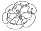
18 is a distal view of an example occlusive device frame.
19 is a conceptual diagram of an example winding jig that may be used to wind the frame of FIG. 18.
20 is an illustration of an elongated, pre-heat-set configuration after laser cutting an example instrument frame from a NiTi tube.
21A, 21B, 21C, 21D, and 21E are diagrams of an example device frame that includes an integrated anchor mechanism.
Like reference symbols in the various drawings indicate like elements.
본 문서는 예를 들어 환자의 신체 내 공간, 구멍, 결함, 개구, 부속기, 관 또는 도관을 폐색하는데 유용한 기기, 시스템 및 방법을 기재한다. 여러 가지 이식가능한 의료 기기가 본원에서 기재되며, 일반적으로 특정 기기에 관해 기재된 임의의 기구(feature)는 또한 본원에서 기재한 임의의 다른 기기와 함께 사용될 수 있다. 일부 실시예에서, 특정 기기에 관해 기재한 1 이상의 기구는 또 다른 기기의 1 이상의 기구를 대신하거나 대체할 수 있다. 일부 실시예에서, 특정 기기에 관해 기재한 1 이상의 기구는 또 다른 기기에 추가되거나 이와 함께 포함될 수 있다. 또한, 본원에서 기재한 임의의 기구의 다양한 조합 또는 부조합(sub-combination)이 일반적으로 본원에서 기재한 임의의 기기와 함께 사용될 수 있다.This document describes, for example, devices, systems, and methods useful for occluding spaces, holes, defects, openings, appendages, tubes, or conduits in a patient's body. Various implantable medical devices are described herein, and generally any feature described with respect to a particular device may also be used with any other device described herein. In some embodiments, one or more instruments described with respect to a particular instrument may replace or replace one or more instruments of another instrument. In some embodiments, one or more instruments described with respect to a particular device may be added to or included with another device. In addition, various combinations or sub-combinations of any of the instruments described herein may be used with any of the devices generally described herein.
일반적으로, 본원에서 기재한 임의의 이식가능한 의료 기기는 다양한 최소 침습 경 카테터(transcatheter) 전개 기술을 사용하여 환자의 신체 내 생체 내 전개 부위에 전달되고, 이 부위에서 전개될 수 있다. 예를 들어, 본원에서 기재한 임의의 이식가능한 의료 기기는 전달 카테터에 해제가능하게 부착될 수 있으며, 기기와 전달 카테터는 전달 시스에 적재될 수 있다. 전달 시스는 환자의 혈관계에 도입되고, 전달 시스의 원위단이 표적 생체 내 전개 부위에 또는 이에 가까이 위치할 때까지, 혈관계를 통해 진행될 수 있다. 이식가능한 의료 기기는 예를 들어 전달 시스를 물러나게 하고/하거나 전달 카테터와 이식가능한 의료 기기를 진행시키고, 전달 카테터로부터 이식가능한 의료 기기를 탈착함으로써 전개 부위에서 전개될 수 있다. 일부 실시에서, 기기의 제1 부분을 전달 시스로부터 해제하며, 반면에 기기의 제2 부분은 전달 시시에 의해 속박되어 유지되고, 기기의 제1 부분의 위치 결정을 확인한 다음, 기기의 제2 부분을 전달 시스로부터 해제한다. 그 후 전달 카테터와 전달 시스를 환자의 신체로부터 빼내거나 물러나게 할 수 있다.In general, any implantable medical device described herein may be delivered to and deployed at an in vivo deployment site in a patient's body using a variety of minimally invasive transcatheter deployment techniques. For example, any implantable medical device described herein may be releasably attached to a delivery catheter, and the device and delivery catheter may be loaded into a delivery sheath. The delivery sheath may be introduced into the patient's vascular system and progress through the vascular system until the distal end of the delivery sheath is located at or near the site of development in the target body. The implantable medical device may be deployed at the deployment site, for example, by withdrawing the delivery sheath and / or by advancing the delivery catheter and implantable medical device, and detaching the implantable medical device from the delivery catheter. In some implementations, the first part of the device is released from the delivery sheath, while the second part of the device is held in bondage by the delivery sash, confirms the positioning of the first part of the device, and then the second part of the device Release from the delivery sheath. The delivery catheter and delivery sheath may then be withdrawn or withdrawn from the patient's body.
본원에서 설명하는 임의의 이식가능한 의료 기기는 인간 심장의 좌심방 부속기(LAA)를 폐색하는데 사용될 수 있다. 이식가능한 의료 기기는 혈관 내 방식으로 카테터 시스템을 통해 또는 위에서 전달 부위, 예컨대 LAA 또는 다른 적합한 전달 부위로 전달되고, 이 부위에서 전개될 수 있다. 이식가능한 의료 기기는 LAA 내에 또는 LAA의 소공을 가로질러 전개되어 예를 들어 좌심방의 주실(main chamber)(좌심방 실)로부터 LAA를 분리할 수 있다. 이는 LAA 내에 혈전 형성 및/또는 LAA로부터 혈전 출구를 방지할 수 있다. 이러한 방식으로, 뇌졸중의 위험을 줄이거나 최소화할 수 있다.Any implantable medical device described herein can be used to occlude the left atrium appendage (LAA) of the human heart. The implantable medical device may be delivered to and deployed at a delivery site, such as LAA or other suitable delivery site, through or above the catheter system in an vascular manner. Implantable medical devices can be deployed within or across the LAA's pores to separate the LAA from, for example, the main chamber (left atrium) of the left atrium. This may prevent thrombus formation in the LAA and / or thrombus exit from the LAA. In this way, the risk of stroke can be reduced or minimized.
일부 실시에서, 본원에서 기재한 기기는 2 이상의 구성을 취할 수 있다. 예를 들어, 기기가 전개 부위로 전달되는 동안, 기기는 접히거나 전달 구성을 취할 수 있다. 기기의 전개 후, 기기는 확장되거나 전개된 구성을 취할 수 있다. 예를 들어, 기기가 전개되는 동안, 기기는 1 이상의 부분 확장되거나 부분 전개된 구성을 취할 수 있다.In some implementations, the devices described herein can take two or more configurations. For example, while the device is delivered to the deployment site, the device may be folded or in a delivery configuration. After deployment of the device, the device may take on an expanded or deployed configuration. For example, while the device is deployed, the device may take one or more partially expanded or partially deployed configurations.
도 1a 및 1b는 각각 환자의 신체 내 구멍, 결함, 개구, 부속기, 관 또는 도관을 폐색하는데 사용될 수 있는 일예의 폐색 기기(100)의 투시도 및 측면도이다. 폐색 기기(100)는 세장 부재(102)로 이루어지는 프레임을 포함하며, 프레임의 적어도 일부를 덮는 막질 피복(104)을 포함한다. 본원에서 사용되는 바와 같이, "프레임"은 기기의 전체 프레임을 의미할 수 있거나, 대안으로 하나 이상의 세장 부재를 포함하는 기기의 국소 부분을 의미할 수 있다.1A and 1B are perspective and side views of an
세장 부재(102)는 일부 실시에서 와이어이다. 예를 들어, 세장 부재(102)는 스프링 와이어, 형상 기억 합금 와이어, 또는 초탄성 합금 와이어일 수 있다. 세장 부재(102)는 니티놀(NiTi), L605 강, 스테인리스강, 또는 임의의 다른 적합한 생체적합성 물질로 제조될 수 있다. 추가로, 특수형의 금속이 사용될 수 있다. 예를 들어, 와이어 코어용으로 백금, 탄탈, 또는 다른 적합한 귀금속을 사용하는 인발 충전관이 향상된 방사선 불투명성을 위해 사용될 수 있다. 일예는 포트 웨인 메탈즈사(Fort Wayne Metals)(인디애나주 포트웨인)가 시판하는 백금 인발 충전 니티놀 와이어이다. 일부 실시형태에서, 생체재흡수성 또는 생체흡수성 물질, 예를 들어 생체재흡수성 또는 생체흡수성 중합체가 사용될 수 있다. 일부 실시에 따라, NiTi의 초탄성 특성은 이것이 세장 부재(102)에 특히 양호한 후보 물질로 되게 한다(예를 들어, NiTi 와이어는 원하는 형상으로 열고정될 수 있다). NiTi는 열고정되어 세장 부재(102)가 제한이 적은 환경에 놓일 때, 예컨대 이것이 전달 시스로부터 체강으로 전개될 때 원하는 형상으로 자기 확장될 수 있다. 세장 부재(102)는 기기(100)를 위한 구조와 형상을 제공할 수 있다. 일반적으로, 본원에서 기재한 기기는 기기의 목적에 맞게 원하는 형상인 세장 부재(102)를 포함한다. 세장 부재(102)는 일반적으로 세장 부재(102)가 축적 길이(stored length)를 갖도록 정합성, 내피로성, 및 탄성일 수 있다. 세장 부재(102)는 이들이 미리 형성된 형상으로 접히고, 길어지게 하는 스프링 특성을 가질 수 있다(예를 들어, 기기의 프레임은 미리 형성된 형상을 가질 수 있다).The
일부 실시형태에서, 세장 부재(102)의 직경 또는 두께는 0.020 mm 내지 0.040 mm일 수 있으나, 다른 실시형태에서 직경이 더 작거나 더 큰 세장 부재가 사용될 수 있다. 일부 실시형태에서, 세장 부재(102)는 직경이 약 0.022 mm이다. 일부 실시형태에서, 세장 부재(102)는 각각 직경이 동일하다. 일부 실시형태에서, 세장 부재(102)의 1 이상의 부분은 직경 방향으로 가늘어질 수 있다. 세장 부재의 테이퍼링(tapering)으로 기기 부분의 강성을 달라지게 할 수 있다. 예를 들어, 기기 강성은 일부 실시에서 기기의 종축을 따라 달라질 수 있다. 세장 부재는 둥근 단면 형상을 가질 수 있거나 둥글지 않은 단면, 예컨대 직사각형 또는 다른 다각형일 수 있다. 세장 부재(102)가 가질 수 있는 다른 단면 형상의 일예는 정사각형, 난형, 직사각형, 삼각형, D형, 부등변 사각형, 또는 편조(braided) 구조 또는 꼬인 구조에 의해 형성된 불규칙 단면 형상을 포함한다. 일부 실시형태에서, 폐색 기기는 평평한 세장 부재(102)를 포함할 수 있다. 일부 실시예에서, 세장 부재(102)는 무심 연삭 기술을 사용하여 형성될 수 있어서, 세장 부재(102)의 직경은 세장 부재(102)의 길이를 따라 달라진다.In some embodiments, the diameter or thickness of the
막질 피복(104)은 늘어나고 접혀서 각각 세장 부재(102)의 확장과 접힘을 제공할 수 있는 다공성, 탄성 부재일 수 있다. 막질 피복(104)의 세공은 혈액, 다른 체액, 및 색전의 통과를 실질적으로, 또는 일부 실시예에서 완전히 방지하는 크기일 수 있다. 일부 실시에서, 막질 피복(104)은 막질 피복(104)을 통해 혈액, 다른 체액, 색전, 또는 다른 신체 물질의 통과를 방지하거나 실질적으로 방지한다. 막질 피복(104)은 폐색 기기(100)의 지속적인 폐색과 보충적인 고정 강도를 위한 조직 내성장 골격을 제공하는 미소공성 구조를 가질 수 있다. 막질 피복(104)의 일부 실시형태는 불소 중합체, 예컨대 발포 폴리테트라플루오로에틸렌(ePTFE) 중합체를 포함한다.The
일부 실시형태에서, 막질 피복(104)은 막질 피복(104)을 통한 유체 통과의 억제가 즉각적이고, 혈전 과정에 의존하지 않도록 구성된다. 일부 실시형태에서, 막질 피복(104)은 막질 피복(104)의 특정 물리적 특성을 향상시키는 1 이상의 화학적 또는 물리적 공정에 의해 변형될 수 있다. 예를 들어, 친수성 코팅이 막질 피복(104)에 도포되어 막질 피복(104)의 습윤성과 에코 투과성(echo translucency)을 개선할 수 있다. 일부 실시형태에서, 막질 피복(104)은 내피 세포 부착, 내피 세포 이동, 내피 세포 증식, 및 혈전증에 대한 저항성 중 1 이상을 촉진하는 화학 부분(moiety)에 의해 변형될 수 있다. 일부 실시형태에서, 막질 피복(104)은 공유 결합된 헤파린에 의해 변형될 수 있거나 상처 치료를 촉진하거나 조직 염증을 줄이도록 계 내에서 유리되는 1 이상의 약물로 함침될 수 있다. 일부 실시형태에서, 약물은 코르티코스테로이드, 인간 성장 인자, 항유사분열제, 항혈전제, 또는 덱사메타손 인산나트륨일 수 있다.In some embodiments, the
일부 실시형태에서, 막질 피복(104)은 불소 중합체(예, 발포 PTFE(ePTFE) 또는 PTFE)로 형성될 수 있다. 일부 실시형태에서, 막질 피복(104)은 폴리에스테르, 실리콘, 우레탄, 또는 또 다른 생체적합성 중합체, 또는 이들의 조합으로 형성될 수 있다. 일부 실시형태에서, 생체재흡수성 또는 생체흡수성 물질, 예를 들어 생체재합수성 또는 생체흡수성 중합체가 사용될 수 있다. 일부 실시형태에서, 막질 피복(104)은 공중합체로 형성될 수 있다. 일부 실시예에서, 막질 피복(104)의 제1 부분은 제1 물질로 형성될 수 있고, 막질 피복(104)의 제2 부분은 제2 물질로 형성될 수 있다. 예를 들어, 기기의 폐색 부재를 덮는 막질 피복(104)의 부분은 제1 물질로 형성될 수 있고, 기기의 지지 부재를 덮는 막질 피복(104)의 부분은 제2 물질로 형성될 수 있다.In some embodiments, the
일예의 폐색 기기(100)는 6개의 세장 부재(102)를 포함하지만, 다른 실시예에서, 그리고 일반적으로 본원에서 설명하는 임의의 기기에 대해, 더 많거나 더 적은 세장 부재(102)가 사용될 수 있다(예를 들어, 2, 3, 4, 5, 7, 8, 9, 10, 11, 12, 또는 그 이상). 상기에 기재한 바와 같이, 기기(100)는 접힌 구조를 취할 수 있으며, 기기(100)의 세장 부재(102)가 늘어나서 기기가 전달 시스 내 위치 결정을 위해 낮은 교차(crossing) 프로파일을 취할 수 있다. 일부 실시예에서, 세장 부재(102)는 기기가 전달 시스로 당겨질 때 접히거나 늘어나게 된다. 시스는 속박 환경을 제공할 수 있으며, 기기가 시스 내에 위치하는 동안 전달 구성으로 기기를 유지할 수 있다. 기기(100)는 전달 시스를 나옴으로써 세장 부재의 바이어스(bias) 또는 형상 기억 특성의 결과로서 자기 확장하도록 구성될 수 있으며, 여기서 기기는 속박 환경으로부터 해방 시 자기 확장할 수 있다. 일예의 폐색 기기(100)가 도 1a 및 1b에 확장 구성으로 도시되어 있으며, 이 구성은 세장 부재(102)의 자기 확장 특성의 결과이다.One
프레임은 또한 본 실시예에서 원위 아일릿(106)과 근위 아일릿(108)을 포함하며, 각각을 본 실시예에서 막질 피복(104)이 덮고 있다. 다른 실시예에서, 원위 아일릿(106), 근위 아일릿(108), 또는 둘 다 막질 피복(104)에 의해 완전히 덮이거나, 막질 피복(104)에 의해 완전히 벗겨 있다. 일부 실시예에서, 아일릿 중 하나 또는 둘 다 부분적으로 막질 피복(104)이 덮고 있다. 원위 아일릿(106)과 근위 아일릿(108)은 1 이상의 세장 부재(102)의 코일형 단부로부터 제조될 수 있다. 다양한 실시에서, 전달 시스템의 1 이상의 구성 요소는 원위 아일릿(106)에서, 근위 아일릿(108)에서, 또는 원위 아일릿(106)과 근위 아일릿(108) 둘 다에서 폐색 기기(100)에 부착될 수 있다. 일부 실시예에서, 원위 아일릿(106)과 근위 아일릿(108) 중 1 이상은 기기(100)를 위한 접속 기구(attachment feature)로서 생각될 수 있다. 이러한 접속 기구는 전개 시스템과 해제가능한 결합을 위한 위치를 제공할 수 있다. 일부 실시에서, 1 이상의 부착 요소 또는 구성 요소는 원위 아일릿(106)에 의해 한정되는 공간 내에 또는 근위 아일릿(108)에 의해 한정되는 공간 내에 위치하며, 1 이상의 전달 시스템 구성 요소는 1 이상의 부착 요소에 해제가능하게 결합할 수 있다. 다양한 실시예에서, 부착은 예를 들어 나사형 연결, 스프링 장착 연결, 스냅 맞춤(snap-fit) 연결, 등에 의한 것일 수 있다.The frame also includes a
폐색 기기(100)는 또한 도시된 실시예에서 고정 앵커(110)를 포함한다. 고정 앵커(110)는 표적 전개 부위에서 기기(100), 또는 기기의 특정 부분의 위치를 고정하도록 표적 전개 부위에서 주위 조직과 접촉할 수 있다. 고정 앵커(110)는 여러 가지 적합한 물질로 제조될 수 있다. 예를 들어, 고정 앵커(110)는 NiTi, L605 강, MP35N 강, 스테인리스강, 중합체 물질, 파이녹스(Pyhnox), 엘질로이(Elgiloy), 또는 임의의 다른 적합한 생체적합성 물질로 제조될 수 있다. 일부 실시형태에서, 고정 앵커(110)는 비영구적인 생체분해성 또는 생체흡수성 물질로 제조될 수 있다. NiTi의 초탄성 특성은 일부 실시에 따라, 이것을 이러한 고정 앵커를 위해 특히 양호한 후보 물질로 만든다. NiTi는 열고정될 수 있어서, 고정 앵커는 고정 앵커가 제한이 적은 환경에 놓일 때, 예컨대 이것이 전달 시스로부터 체강으로 전개될 때 원하는 형상으로 자기 확장할 수 있다. 일부 실시형태에서, 고정 앵커는 바이어스를 걸어서 고정 앵커의 고정 특성을 향상시키는 특정 형상을 갖는 것이 바람직하다. 일부 실시형태에서, 기기(100)는 고정 앵커(110)를 포함하지 않는다.The
본원에서 기재한 기기는 때로 처음 위치로 전개 후 위치를 바꿀 수 있거나, 현 전개 위치로부터 회복될 수 있다. 기기 재배치의 일환으로서, 기기를 예를 들어 전달 시스로 후퇴할 수 있다. 본원에서 기재한 앵커(전개 시 조직을 뚫도록 설계된 앵커, 및 전개 시 조직을 뚫지 않거나 단지 최소로 뚫도록 설계된 앵커 둘 다에 대해)는 기기의 재배치 또는 회복 시 조직 손상을 최소화하는데 적합화될 수 있다. 예를 들어, 앵커는 조직에 실질적인 추가 외상없이 회복 시 조직을 단념할 수 있다. 이러한 기구는 예를 들어 외상, 심막 저류, 주요 천공, 또는 미란(erosion)을 줄이거나 최소화할 수 있다.The instrument described herein can sometimes be repositioned after deployment to the initial position or can be recovered from the current deployment position. As part of the device relocation, the device can be retracted, for example, to a delivery sheath. The anchors described herein (both for anchors designed to penetrate tissue at development and anchors designed to penetrate or only minimally penetrate tissue at deployment) may be adapted to minimize tissue damage during relocation or recovery of the instrument. have. For example, an anchor can give up tissue upon recovery without substantial additional trauma to the tissue. Such instruments can reduce or minimize, for example, trauma, pericardial retention, major perforation, or erosion.
기기(100)는 근위 영역(112), 원위 영역(114), 및 근위 영역(112)과 원위 영역(114) 사이의 전이 영역(116)을 포함한다. 근위 영역(112), 원위 영역(114), 및 전이 영역(116)은 각각 각 구역에서 세장 부재(102)의 형태에 의해 한정된다. 일반적으로, 각 영역의 형태 또는 지형은 기기의 목적에 맞도록 원하는 대로 선택될 수 있으며, 기기(100)의 세장 부재(102)는 기기를 구성하는데 감기고, 열고정되어 전개된 구성에서, 세장 부재(102)가 원하는 형태 또는 지형을 취할 수 있다.The
본 실시예에서, 세장 부재(102)는 각각의 근위 영역(112)과 원위 영역(114)에서 기구를 형성하도록 성형된다. 처음에 근위 영역(112)에 관해, 세장 부재(102)는 환자의 신체 내 전개 부위에서 공간, 구멍, 결함, 개구, 부속기, 관 또는 도관을 실질적으로 밀봉하는데 사용될 수 있는 폐색 디스크 또는 폐색 구를 일반적으로 집합적으로 형성하도록 성형된다. 세장 부재(102)는 원위 영역(114)에서 기기에 대한 지지를 제공할 수 있고, 전달 부위에서 특정 위치에 기기를 위치시키거나 고정하는데 사용될 수 있는 제2 디스크 또는 구를 일반적으로 형성하도록 성형된다. 대신 굴절 영역 또는 허리 영역으로서 지칭될 수 있는, 전이 영역(116) 내에서, 세장 부재(102)는 근위 영역(112)에서 형성된 기구로부터 원위 영역(114)에서 형성된 기구로 전이한다. 일부 실시예에서, 세장 부재(102)는 개구를 적절히 폐색하거나 부분적으로 폐색하는 1 이상의 폐색 기구를 형성하도록 성형될 수 있다. 다양한 실시에서, 이러한 폐색 기구는 근위 영역(112)에, 원위 영역(114)에, 전이 영역(116)에, 또는 이전의 조합 영역에 포함될 수 있다.In this embodiment, the
원위 영역(114)과 원위 아일릿(106)은 "원위"로서 지칭되며, 그 이유는 전개 후, 이들의 위치가 일반적으로 전달 시스템에 관해 기기의 다른 부분의 원위이기 때문이다. 비교하여, 근위 영역(112)과 근위 아일릿(108)은 "근위"로서 지칭되며, 그 이유는 이들의 전개된 위치가 기기의 다른 부분과 비교하여 일반적으로 전달 시스템에 근위이기 때문이다. 일부 실시예에서, 원위 아일릿(106)과 원위 영역(114)이 전달 시스로부터 처음에 전개되고, 전이 영역(116)이 다음에 전개되며, 끝으로 근위 영역(112)과 근위 아일릿(108)이 전달 시스로부터 전개된다. LAA에 관해, 기기의 전개 후, 원위 아일릿(106)은 LAA의 내부로 향하게 배향될 수 있으며, 반면에 근위 영역(112)과 근위 아일릿(108)의 근위로 향한 면은 심장의 좌심방으로 향하게 배향될 수 있다.
도 2는 일예의 폐색 기기의 일예의 프레임(200)의 투시도이다. 예를 들어, 프레임(200)은 도1a 및 1b의 폐색 기기(100)의 프레임에 상응할 수 있지만, 막질 피복(104)이 제거되어 있다. 세장 부재(202)는 도 1a 및 1b의 세장 부재(102)에 상응하며; 원위 아일릿(206)은 도 1a 및 1b의 원위 아일릿(106)에 상응하고; 근위 아일릿(208)은 도 1a 및 1b의 근위 아일릿(108)에 상응하며; 고정 앵커(210)는 도 1a 및 1b의 고정 앵커(110)에 상응한다.2 is a perspective view of an
일반적으로, 본원에서 기재한 임의 기기에 대한 프레임은 1 이상의 세장 부재로부터 구성될 수 있다. 기기는 일부 실시예에서 모듈러 공구를 사용하여, 또는 다른 실시예에서 지그 장치를 사용하여 구성될 수 있다. 일부 실시에서, 기기 프레임은 일반적으로 다음과 같이 감길 수 있다: 제1 아일릿(예, 원위 아일릿)을 맨드릴(mandrel) 주위에 감을 수 있다. 일부 실시예에서, 아일릿을 둥근 단면이 있는 맨드릴 상에 감을 수 있어서, 아일릿은 또한 단면이 둥글다. 다른 실시예에서, 아일릿을 둥글지 않은 단면, 예컨대 난형 단면이 있는 맨드릴 상에 감을 수 있어서, 아일릿은 난형 형상을 갖는다. 둥근 단면이 없는 이러한 아일릿은 "키 있는"(keyed) 아일릿으로서 언급될 수 있으며, 2개의 아일릿 기기가 키 있는 아일릿을 포함할 경우, 예를 들어, 아일릿 정렬이 개선될 수 있다. 다음에, 제1 영역(예, 원위 영역)의 1 이상의 기구를 감을 수 있으며; 제2 영역(예, 근위 영역)의 1 이상의 기구를 감을 수 있고; 제2 아일릿(예, 근위 아일릿)을 맨드릴 주위에 감을 수 있다. 일부 실시예에서, 제3 영역(예, 전이 영역)의 1 이상의 기구는 추가의 권선 단계를 포함할 수 있으며, 상기 실시예에서 추가의 권선 단계는 제1 영역의 기구를 감는 단계 후에 발생할 수 있다. 다른 실시예에서, 상기에 기재한 권선 순서는 반대일 수 있어서, 근위 아일릿을 처음에 감고, 원위 아일릿을 나중에 감는다. 프레임의 세장 부재는 불소화 에틸렌 프로필렌(FEP) 또는 또 다른 적합한 접착제 물질로서 완전히 또는 부분적으로 코팅되고, 베이킹하여 프레임을 열고정할 수 있다.In general, the frame for any of the devices described herein may be constructed from one or more elongate members. The device may be configured using a modular tool in some embodiments, or using a jig device in other embodiments. In some implementations, the appliance frame may generally be wound as follows: A first eyelet (eg, distal eyelet) may be wound around the mandrel. In some embodiments, the eyelets may be wound on a mandrel having a round cross section so that the eyelets are also round in cross section. In another embodiment, the eyelets may be wound on a mandrel with a non-round cross section, such as an oval cross section, such that the eyelets have an oval shape. Such eyelets without a rounded cross section may be referred to as "keyed" eyelets, and if two eyelet devices include keyed eyelets, for example, eyelet alignment may be improved. Next, one or more instruments of the first region (eg, distal region) may be wound; One or more instruments of the second region (eg, proximal region) can be wound; A second eyelet (eg proximal eyelet) may be wound around the mandrel. In some embodiments, one or more instruments of the third region (eg, transition region) may comprise additional winding stages, in which further winding stages may occur after winding the instruments of the first region. . In another embodiment, the winding sequence described above can be reversed, so that the proximal eyelet is wound first and the distal eyelet is wound later. The elongate member of the frame may be completely or partially coated with fluorinated ethylene propylene (FEP) or another suitable adhesive material and baked to heat the frame.
예를 들어, 권선 지그 또는 모듈러 공구를 사용하고, 1 이상의 핀, 바, 블록, 채널, 또는 기구 한정 지그 구성 요소에 의해 한정되는 권선 경로를 따라 각 세장 부재를 안내함으로써 세장 부재를 감아서 기기의 기구를 원하는 대로 만들 수 있다. 예를 들어, 지그 장치를 사용하는 경우, 세장 부재는 지그 장치에 의해 한정되거나 지그 장치의 기구에 의해 결정되는 소정의 경로를 따를 수 있다. 예를 들어, 일정수의 세장 부재가 있는 소정의 기기에 대해, 제1 아일릿은 핀 또는 맨드릴 주위에 코일형 방식으로 세장 부재의 제1 단부를 감음으로써 만들어질 수 있다. 그 후 세장 부재를 제1 아일릿으로부터 펼쳐서(예를 들어, 모듈러 공구를 사용하는 경우), 세장 부재를 1 이상의 기구 한정 구성 요소 주위에 감음으로써 제1 영역의 기구를 한정할 수 있거나, 예를 들어 지그 장치의 소정 경로를 따라 전송할 수 있다. 그 후 세장 부재를 1 이상의 기구 한정 지그 구성 요소(또는 모듈러 공구 공정에 대해 공구 기구) 주위에 감아 제2 영역의 기구를 한정할 수 있으며, 그 후 세장 부재의 제2 단부를 핀 또는 맨드릴 주위에 코일형 방식으로 다시 감아 제2 아일릿을 한정할 수 있다. 필요에 따라 형성된 기기에 열고정 공정을 적용할 수 있다. 상기에 기재한 바와 같이, 원형, 난형, 또는 다른 단면 형상을 가진 맨드릴을 사용할 수 있다. 일부 실시에서, 근위 및 원위 아일릿을 기기의 종축을 따라 정렬한다.For example, the elongate member may be wound by using a winding jig or modular tool and guiding each elongate member along a winding path defined by one or more pins, bars, blocks, channels, or instrument defining jig components. You can customize the apparatus as you wish. For example, when using a jig device, the elongate member may follow a predetermined path defined by the jig device or determined by the mechanism of the jig device. For example, for certain appliances with a certain number of elongate members, the first eyelet may be made by winding the first end of the elongate member in a coiled fashion around a pin or mandrel. The elongate member may then be unfolded from the first eyelet (eg, when using a modular tool) to wind the elongate member around one or more instrument defining components, or may define, for example, the mechanism of the first region. It can transmit along a predetermined path of the jig device. The elongate member may then be wound around one or more instrument defining jig components (or tool instruments for a modular tooling process) to define the second region of the instrument, and then the second end of the elongated member may be wrapped around a pin or mandrel. It can be rewound in a coiled fashion to define the second eyelet. If necessary, a heat setting process may be applied to the formed device. As described above, mandrels having circular, oval, or other cross-sectional shapes can be used. In some implementations, the proximal and distal eyelets are aligned along the longitudinal axis of the device.
일부 실시형태에서, 프레임(200)은 6개의 세장 부재(202)(202a, 202b, 202c, 202d, 202e, 및 202f로 분류됨)를 포함한다. 6개의 세장 부재(202a-202f) 중 각각의 제1 단부는 근위 아일릿(208)을 형성하고, 세장 부재(202a-202f) 중 각각의 제2 (반대 측) 단부는 원위 아일릿(206)을 형성한다. 본 실시예에서, 근위 영역과 원위 영역(예를 들어, 도 1b의 근위 영역(112) 및 원위 영역(114)에 상응함)의 기구가 아일릿 사이에 있다. 세장 부재(202a)에 관해, 세장 부재(202a)는 근위 아일릿(208)으로부터 연장되어 근위 기구(212a)를 형성한다. 근위 기구(212a)는 일반적으로 기기의 "꽃잎"으로서 언급될 수 있으며, 일반적으로 기기의 근위 영역(예를 들어, 도 1b의 기기 중 영역(112)에 상응함)에 위치할 수 있다. 기기의 전이 영역(예를 들어, 도 1b의 기기 중 영역(116)에 상응함)을 통과한 후, 세장 부재(202a)는 원위 기구(214a)를 형성한다. 원위 기구(214a)는 일반적으로 기기의 원위 영역(예를 들어, 도 1b의 기기 중 영역(114)에 상응함)에 위치할 수 있다.In some embodiments,
유사하게, 각각의 세장 부재(202b-202f)는 근위 아일릿(208)으로부터 연장되어 기기의 근위 영역에 각 근위 기구를 형성하며, 기기의 전이 영역을 통과하고, 기기의 원위 영역에 각 원위 기구를 형성한다. 6개의 근위 기구 또는 꽃잎은 일반적으로 근위 아일릿(208) 주위에 등거리로 간격을 둘 수 있으며, 6개의 근위 기구는 모두 합쳐 프레임(200)의 폐색 기구를 형성할 수 있다(예를 들어, 프레임 또는 프레임의 부분을 막질 피복이 덮는다). 예를 들어, 프레임의 근위 기구를 막질 피복이 덮을 경우, 폐색 기구는 환자의 체 내에서 LAA, 또는 다른 공간, 구멍, 결함, 개구, 부속기, 관 또는 도관을 폐색하는데 사용될 수 있다. 유사하게, 6개의 원위 기구는 일반적으로 원위 아일릿(206) 주위에 등거리로 간격을 둘 수 있고, 6개의 원위 기구는 모두 합쳐 프레임(200)의 지지 기구를 형성할 수 있다.Similarly, each
고정 앵커(210)는 일반적으로 상응하는 세장 부재(202) 주위에 감기거나 고리로 감겨 고정 앵커(210)를 기기의 프레임에 고정하는 프레임 부착부(216), 및 전개 부위에서 신체 조직에 기기를 결박하거나, 잡아매거나, 고정할 수 있어서 체 내에서 기기의 이동을 줄이거나 최소화할 수 있는 앵커부(218)를 포함한다. 도시한 실시예에서, 고정 앵커(210)는 프레임 앵커 와이어를 포함한다. 프레임 앵커 와이어의 제1 부분은 프레임 부착부(216)의 일부로서 상응하는 세장 부재(202) 주위에 감기거나 고리로 감긴다. 프레임 앵커 와이어의 제2 부분은 앵커부(218)의 루프(loop) 또는 부트(boot)를 형성한다. 프레임 앵커 와이어의 제3 부분은 프레임 부착부(216)의 일부로서 세장 부재(202)와 프레임 앵커 와이어의 코일형 부분 사이에 위치하여서, 와이어의 코일형 부분은 세장 부재와 프레임 앵커 와이어의 이 제3 부분 둘 다 주위에 고리 모양을 만든다. 일부 실시에서, 프레임 앵커 와이어의 코일형 부분이 세장 부재(202)와 프레임 앵커 와이어의 제3 부분 둘 다 주위에 고리 모양을 만들므로, 예를 들어, 고정 앵커(210)는 프레임과 더 양호한 맞물림이 있을 수 있고, 세장 부재(202) 주위를 미끄러지거나 회전할 가능성이 더 적을 수 있다. 예를 들어, 이러한 경우에 코일형 부분은 세장 부재(202)와 동심원일 뿐만 아니라, 프레임 앵커 와이어의 제3 부분과 동심원이다. 일부 실시예에서, 프레임 부착부(216) 및/또는 세장 부재(202)의 상응하는 부분은 FEP 또는 또 다른 적합한 접착제 물질로 코팅되어 고정 앵커(210)의 프레임 부착부(216)를 프레임(200)에 고정한다.The anchoring
본원에서 설명하는 고정 앵커는 여러 가지 적합한 물질로 제조될 수 있다. 예를 들어, 고정 앵커는 NiTi, L605 강, 스테인리스강, 중합체 물질, 또는 임의의 다른 적합한 생체적합성 물질로 제조될 수 있다. 일부 실시형태에서, 고정 앵커는 비영구적인 생체분해성 또는 생체흡수성 물질로부터 제조될 수 있다. NiTi의 초탄성 특성은 일부 실시에 따라, 이것을 이러한 고정 앵커를 위해 특히 양호한 후보 물질로 만든다. NiTi는 열고정될 수 있어서, 고정 앵커는 고정 앵커가 제한이 적은 환경에 놓일 때, 예컨대 이것이 전달 시스로부터 체강으로 전개될 때 원하는 형상으로 자기 확장할 수 있다. 일부 실시형태에서, 고정 앵커는 바이어스를 걸어서 고정 앵커의 고정 특성을 향상시키는 특정 형상을 갖는 것이 바람직하다.The anchoring anchors described herein can be made from a variety of suitable materials. For example, the anchoring anchor can be made of NiTi, L605 steel, stainless steel, polymeric material, or any other suitable biocompatible material. In some embodiments, anchoring anchors can be made from non-permanent biodegradable or bioabsorbable materials. The superelastic properties of NiTi, according to some implementations, make it a particularly good candidate for such anchor anchors. NiTi can be heat-set so that the anchoring anchor can self-expand to the desired shape when the anchoring anchor is placed in a less constrained environment, such as when it is deployed from the delivery sheath into the body cavity. In some embodiments, it is desirable for the anchoring anchor to have a particular shape that biases to improve the anchoring characteristics of the anchoring anchor.
일부 실시에서, 본원에서 설명하는 고정 앵커는 기기의 프레임을 한정하는 세장 부재와 별개이거나 다른 1, 2, 또는 그 이상의 세장 부재(예, 와이어)로부터 형성된다. 고정 앵커(210) 중 소정의 고정 앵커 와이어에 대해, 고정 앵커 와이어의 제1 부분을 세장 부재(202) 주위에 감거나 휘감을 수 있다. 고정 앵커 와이어의 제2 부분은 앵커부(218)를 형성하는데 사용될 수 있으며, 이는 도 2의 도시한 실시예에서 일반적으로 난형 루프를 포함하고, 고정 앵커 와이어의 제3 부분을 세장 부재(202) 주위에 감을 수 있다. 도 2의 실시예에서, 고정 앵커 와이어의 제3 부분을 일반적으로 고정 앵커의 제1 부분과 동일한 세장 부재(202)의 구역 주위에 감고, 고정 앵커의 제1 및 제3 부분은 함께 프레임 부착부(216)를 포함한다. 타원형, 원형, 삼각형, 정사각형, 직사각형, 다이아몬드형, 또는 다른 다각형을 포함하여, 난형 이외의 루프 형상이 앵커부(218)를 위해 사용될 수 있다.In some implementations, the anchoring anchors described herein are formed from one, two, or more elongate members (eg, wires) separate or different from the elongate members defining the frame of the device. For certain fixed anchor wires of the fixed
일반적으로, 본원에서 설명하는 고정 요소(하기에 더 상세히 설명되는, 미세 코일 앵커를 포함하여)는 기기의 프레임을 한정하는 세장 요소와 별개인 세장 요소 또는 고정 앵커 와이어를 포함할 수 있다. 일부 실시형태에서, 고정 앵커 와이어는 각각 직경이 동일하다. 일부 실시형태에서, 고정 앵커 와이어의 1 이상의 부분은 직경 방향으로 가늘어질 수 있다. 고정 앵커 와이어는 둥근 단면 형상일 수 있거나 둥글지 않은 단면 형상, 예컨대 직사각형 또는 다른 다각형일 수 있다. 고정 앵커 와이어가 가질 수 있는 다른 단면 형상의 일예는 정사각형, 난형, 직사각형, 삼각형, D형, 부등변 사각형, 또는 편조 구조에 의해 형성된 불규칙 단면 형상을 포함한다. 일부 실시형태에서, 폐색 기기는 평평한 고정 앵커 와이어를 포함할 수 있다. 일부 실시예에서, 고정 앵커 와이어는 무심 연삭 기술을 사용하여 형성될 수 있어서, 고정 앵커 와이어의 직경은 고정 앵커 와이어의 길이를 따라 달라진다.In general, the fastening elements described herein (including the fine coil anchor, described in more detail below) may include an elongate element or a fastening anchor wire that is separate from the elongate element defining the frame of the device. In some embodiments, the anchor anchor wires are each the same diameter. In some embodiments, one or more portions of the anchor anchor wires can be tapered in the radial direction. The anchor anchor wires may be round cross-sectional shapes or may be non-round cross-sectional shapes, such as rectangular or other polygons. Examples of other cross-sectional shapes that a fixed anchor wire may have include irregular cross-sectional shapes formed by square, ovoid, rectangular, triangular, D-shaped, trapezoidal, or braided structures. In some embodiments, the occlusion device can include a flat anchoring wire. In some embodiments, the anchor anchor wires may be formed using a centerless grinding technique, such that the diameter of the anchor anchor wires vary along the length of the anchor anchor wires.
도시한 실시예에서, 고정 앵커(210)는 기기의 원위 영역(114)(도 1b 참조)에서 세장 부재(202)의 부분 위에 포함된다. 일부 실시예에서, 고정 앵커(210)는 프레임의 근위 영역(112)에서 세장 부재(202)의 부분 위에 포함될 수 있으며, 원위 영역(114)에 포함되지 않을 수 있다. 일부 실시예에서, 고정 앵커(210)는 원위 영역(114) 및 근위 영역(112)의 양쪽 위에 포함될 수 있다. 일부 실시예에서, 고정 앵커는 전이 영역(116) 위에 포함될 수 있다. 도 8a-8e는 일예의 폐색 기기 위에서 가능한 고정 앵커 위치의 일부 실시예를 보여준다.In the illustrated embodiment, the anchoring
도시한 실시예에서, 한 고정 앵커(210)가 프레임의 원위 영역에서 각각의 세장 부재(202) 위에 포함된다. 또 다른 방식으로 언급하자면, 프레임의 원위 영역(114)의 기구(본 실시예에서 6개)는 각각 고정 앵커(210)를 포함한다. 일부 실시에서, 세장 요소 중 1 이상은 고정 앵커(210)를 포함하지 않는다. 예를 들어, 일부 실시에서, 세장 부재의 제1 서브세트(subset)은 1 이상의 고정 앵커(210)를 포함하며, 세장 부재의 제2 서브세트는 고정 앵커(210)를 포함하지 않는다. 다양한 실시예에서, 세장 부재(202)에 1부터 n까지(본 실시예에서 프레임(200)이 6개의 와이어를 포함하므로 1 내지 6) 연속으로 번호를 매기면, 홀수 세장 부재는 고정 앵커를 포함할 수 있으며, 반면에 짝수 세장 부재는 고정 앵커를 포함하지 않을 수 있거나, 서로 반대일 수 있다. 또 다른 방식으로 언급하자면, 세장 요소는 하나 걸러 고정 앵커(210)를 포함할 수 있다(예를 들어, 세장 요소(202a, 202c, 및 202e); 또는 요소(202b, 202d, 202f)). 다른 실시예에서, 세장 요소는 2개 걸러 고정 앵커를 포함할 수 있다(예를 들어, 요소(202a 및 202d); 또는 요소(202b 및 202e); 또는 요소(202c 및 202f)).In the illustrated embodiment, one
도 2에서 앵커(210)를 포함하여, 프레임 한정 세장 부재(202) 주위에 감기거나 고리로 감긴 고정 앵커 부재 적어도 일부를 포함하는 프레임 부착부를 포함하는 고정 앵커는 일반적으로 "미세 코일" 앵커로 언급될 수 있다. 미세 코일 고정 앵커는 도 3a-3c, 4a-4d, 5a-5f, 6a, 6b, 7a-7e, 및 8a-8e에 관해 하기에 추가로 기재되듯이, 많은 상이한 형상과 스타일을 가질 수 있다. 일반적으로, 미세 코일 고정 앵커는 전개 부위에서 신체 조직에 침투하기 위해 적합화된 능동 앵커부를 포함할 수 있거나, 일반적으로 신체 조직을 뚫지 않고서, 전개 부위에서 신체 조직과 비외상적으로 접촉하기 위해 적합화된 수동 앵커부를 포함할 수 있다. 고정 앵커(210)의 앵커부(218)는 이러한 수동 앵커형이다. 수동 앵커부는 일반적으로 조직의 최소 침투로 조직에 맞물리는데 목적이 있다.In FIG. 2, a fixing anchor including a frame attachment including at least a portion of a fixing anchor member wound or wound around the frame defining elongate member 202, including the
도 3a-3c는 각각 일예의 고정 앵커(310a, 310b, 및 310c)의 측면도이다. 앵커(310a, 310b, 및 310c)는 각각 미세 코일 앵커로 생각될 수 있으며, 각각 수동 앵커부(318)를 포함한다. 앵커(310a, 310b, 및 310c)는 각각 세장 부재, 예컨대 와이어를 포함하며, 전개 부위에서 신체 조직과 비외상 접촉에 적합화된 앵커부(318)를 포함한다. 고정 앵커 와이어의 프레임 부착부(316)는 각각 의료 기기의 상응하는 프레임 한정 세장 부재(302) 주위에 감기거나 고리로 감긴다. 일부 실시에서, 프레임 부착부(316) 및/또는 세장 부재(302)의 상응하는 부분은 FEP 또는 또 다른 적합한 접착제 물질로 코팅되어 고정 앵커(310)의 프레임 부착부(316)를 프레임의 세장 부재(302)에 고정할 수 있으며, 일부 실시에서 와이어는 FEP 또는 다른 접착제의 추가 없이 세장 부재(302) 주위에 고리로 감긴다. 일부 실시예에서, 앵커는 세장 부재에 용접되거나 납땜될 수 있다.3A-3C are side views of one example of anchoring
도 3a에 관해, 앵커부(318a)는 돌출 루프를 포함할 수 있다. 본 실시예에서, 루프의 각 측면 또는 다리(leg)는 세장 부재(302)의 동일한 측면 위에 위치한다. 일부 실시예에서, 루프는 세장 부재(302)의 방사상 외측으로 향한 면 위에 위치할 수 있으며, 일부 실시예에서 루프는 세장 부재(302)의 방사상 내측으로 향한 면 위에 위치할 수 있다. 앵커(310a)는 앵커부(318a)의 각 측면에 하나씩 제1 및 제2 프레임 부착부(316a)를 포함한다. 앵커부(318a)는 돌출 루프를 포함할 수 있다.With respect to FIG. 3A,
도 3b의 고정 앵커(310b)는 또한 돌출 루프를 포함하는 앵커부(318b)를 포함하지만, 본 실시예에서 루프의 측면 또는 다리는 세장 부재(302)의 반대 측 위에 위치한다. 루프는 후방으로 각이 있는 곡면 또는 굴곡을 포함하며, 이는 전개 부위에서 조직과 수동 맞물림을 용이하게 할 수 있다. 앵커(310b)는 앵커부(318b)의 각 측면에 하나씩 제1 및 제2 프레임 부착부(316b)를 포함한다.The anchoring
도 3c의 고정 앵커(310c)는 또한 돌출 루프를 포함하는 앵커부(318c)를 포함하지만, 본 실시예에서 앵커부(318c)는 중간이 아니라 앵커의 끝에 있다. 즉, 본 실시예에서 프레임 부착부(316c)는 앵커부(318c)의 오른쪽(예를 들어, 원위)에 위치한다. 다른 실시예에서, 프레임 부착부(316c)는 앵커부(318c)의 근위에 위치할 수 있다. 일부 실시예에서, 앵커부(318c)의 루프는 축 방향으로 향하며, 축 방향으로 맞물리고, 축 방향으로 이동을 방지할 수 있다. 일예의 앵커(310a, 310b, 및 310c)는 각각 신체 조직과 비외상 접촉을 위해 설계된 앵커부를 포함하는 것으로서 도시되어 있지만, 다른 실시에서 상응하는 앵커 기구의 부분은 예를 들어 신체 조직을 침투하도록 설계된 예리한 선단 또는 미늘(barb)을 포함할 수 있다.The anchoring
도 4a-4d는 각각 일예의 고정 앵커(410a, 410b, 410c, 및 410d)의 측면도이다. 앵커(410a, 410b, 410c, 및 410d)는 각각 미세 코일 앵커로 생각될 수 있으며, 각각 능동 앵커부(418)를 포함한다. 앵커(410a, 410b, 410c, 및 410d)는 각각 세장 부재, 예컨대 와이어를 포함하며, 전개 부위에서 신체 조직을 뚫어서 기기를 고정하고, 전개 후 기기의 이동을 최소화하거나 방지하는데 적합화된 앵커부(418)를 포함한다. 고정 앵커 와이어의 프레임 부착부(416)는 각각 의료 기기의 상응하는 프레임 한정 세장 부재(302) 주위에 감기거나 고리로 감긴다. 일부 실시에서, 프레임 부착부(416) 및/또는 세장 부재(302)의 상응하는 부분은 FEP 또는 또 다른 적합한 접착제 물질로 코팅되어 고정 앵커(410)의 프레임 부착부(416)를 프레임의 세장 부재(302)에 고정할 수 있으며, 일부 실시에서 와이어는 FEP 또는 다른 접착제의 추가 없이 세장 부재(302) 주위에 고리로 감긴다. 일부 실시예에서, 앵커는 세장 부재에 용접되거나 납땜될 수 있다.4A-4D are side views of
도 4a에 관해, 앵커부(418a)는 축 방향으로 향한 미늘을 포함한다. 일부 실시예에서, 앵커부(418a)의 미늘은 축 방향으로 향하고, 축 방향으로 맞물리고, 축 방향으로 이동을 방지할 수 있다. 도 4b의 앵커(410b)는 코르크스크루 스타일 앵커부(418b)를 포함한다. 코르크스크루 스타일 앵커부(418c)는 기기 프레임의 회전에 의해 조직과 맞물릴 수 있다. 도 4c의 앵커(410c)는 수직선에서 각도 알파(α)로 비스듬하거나 각이 있는 앵커부(418c)를 포함하며, 각도는 예를 들어 원하는 맞물림 특성에 기초하여 조정될 수 있다. 일부 실시예에서, 각도(α)는 영 내지 45 도 범위일 수 있다(예를 들어, 0 도, 10 도, 20 도, 30 도, 40 도, 45 도). 앵커부(418c)는 일부 실시에서 α의 선택에 기초하여 원하는 각도에서 조직과 맞물릴 수 있다. 도 4d의 앵커(410d)는 조직 표면을 관통하고, 조직으로 일정 거리 이어진 다음, 조직 표면을 다시 뚫는데 적합하고, 공정 중 조직을 모으는 일반적으로 "J"와 같은 형상인 앵커부(418d)를 포함한다. 일부 실시에서, 이는 예를 들어 조직의 추가 절단 또는 전단을 방지할 수 있다. 일반적으로, 능동 앵커부는 예를 들어 단지 소정 거리로 조직을 침투하는데 적합할 수 있다.With respect to FIG. 4A, the
도 5a-5d는 각각 일예의 고정 앵커(510a, 510b, 510c, 및 510d)의 측면도이다. 앵커(510a, 510b, 510c, 및 510d)는 각각 미세 코일 앵커로 생각될 수 있으며, 각각 다수의 조직 천공 부재가 있는 능동 앵커부(518)를 포함한다. 앵커(510a, 510b, 510c, 및 510d)는 각각 1 또는 2개의 세장 부재, 예컨대 와이어(들)를 포함하며, 전개 부위에서 신체 조직을 뚫어서 기기를 고정하고, 전개 후 기기의 이동을 최소화하거나 방지하는데 적합화된 앵커부(518)를 포함한다. 고정 앵커 와이어의 프레임 부착부(516)는 각각 의료 기기의 상응하는 프레임 한정 세장 부재(302) 주위에 감기거나 고리로 감긴다. 일부 실시에서, 프레임 부착부(516) 및/또는 세장 부재(302)의 상응하는 부분은 FEP 또는 또 다른 적합한 접착제 물질로 코팅되어 고정 앵커(510)의 프레임 부착부(516)를 프레임의 세장 부재(302)에 고정할 수 있으며, 일부 실시에서 와이어는 FEP 또는 다른 접착제의 추가 없이 세장 부재(302) 주위에 고리로 감긴다. 일부 실시예에서, 앵커는 세장 부재에 용접되거나 납땜될 수 있다.5A-5D are side views of
도 5a에 관해, 앵커는 단일 앵커 와이어를 포함하며, 하나는 전방으로 향하고, 나머지는 세장 부재(302)를 따라 후방으로 향하는, 2개의 상이한 미늘을 포함하는 앵커부(518a)를 포함한다. 일부 실시예에서, 앵커부(518a)의 미늘들은 반대 방향에서 축 방향으로 향하며(즉, 축 방향 대향 방향으로), 축 방향으로 맞물릴 수 있고, 축 방향 치수(axial dimension)의 각 방향에서 이동을 방지할 수 있다. 앵커부(518c)의 2개 미늘은 단일 앵커 와이어의 반대 측 끝일 수 있다. 도 5b의 앵커(510b)는 2개의 앵커 와이어를 포함하며, 각각 동일한 방향에서 축 방향으로 향하고, 일반적으로 약 180 도 떨어져 간격을 둔 2개의 상이한 미늘을 포함하는 앵커부(518b)를 포함한다. 앵커 와이어는 각각 프레임 앵커부(516b)를 포함한다. 앵커(510b)는 이중사(dual-filar) 앵커일 수 있으며, 그 이유는 이것이 2개의 앵커 와이어를 포함하기 때문이다.With regard to FIG. 5A, the anchor includes a single anchor wire, one comprising an
도 5c의 앵커(510c)는 2개의 앵커 와이어를 포함하며, 2개의 상이한 미늘을 포함하는 앵커부(518c)를 포함하고, 2개의 미늘은 세장 부재(302)를 따라 상이한 종 위치에 위치한다. 앵커(510c)는 이중사, 종 해제 앵커일 수 있다. 도 5d의 앵커(510d)는 일반적으로 서로 접촉하여 쌍을 이루거나 경로를 따르는 2개의 앵커 와이어를 포함한다. 이는 일부 실시에서 프레임과 낮은 프로파일을 유지하면서 앵커(510d)의 강성을 증가시킬 수 있다. 앵커부(518d)는 굴곡을 포함하며, 2개의 와이어는 굴곡에서 함께 용접되거나 납땜될 수 있다. 글곡은 다양한 각도로 있을 수 있으며, 축 방향으로 있을 수 있다. 일부 실시에서, 앵커(510d)는 쌍 와이어를 미늘로 종료시키지 않고 도 3a-3c에 도시한 앵커와 유사한 방식으로 쌍 와이어를 고리로 감음으로써 수동 앵커부를 갖도록 형성될 수 있다. 쌍 와이어 실시형태의 프레임 부착부(516)는 열린 피치(open pitch)를 포함하며, 이는 프레임에 접착제 부착을 용이하게 할 수 있다.The
도 5e와 5f는 일예의 고정 앵커의 단부 도면이며, 1, 2, 또는 3개의 미늘을 포함하는 앵커부에 대해, 미늘이 다양한 각도 위치에서 배향될 수 있다는 것을 도시한다. 도 5e는 대표 앵커의 2개 미늘을 분리하는 제1 각도(α)를 도시한다. 도 5f는 대표 앵커의 2개 미늘을 분리하는 제2 각도(β)를 도시하며, β는 α보다 크다. 일부 실시예에서, 앵커의 미늘 사이의 각도가 클수록 더 큰 앵커 곡선(sweep) 또는 더 큰 앵커 피복률(coverage)을 제공할 수 있다.5E and 5F are end views of an example anchoring anchor, showing that the barbs may be oriented at various angular positions relative to the anchor portion comprising one, two, or three barbs. 5E shows the first angle α separating the two barbs of the representative anchor. 5F shows the second angle β separating the two barbs of the representative anchor, wherein β is greater than α. In some embodiments, larger angles between the barbs of the anchors may provide greater anchor sweeps or greater anchor coverage.
도 6a와 6b는 각각 일예의 고정 앵커의 일예의 앵커 부착부(616a 및 616b)의 측면도이다. 앵커 부착부(616a 및 616b)는 소정의 고정 앵커에 대해 앵커 부착부의 피치가 앵커 부착부를 따라 달라질 수 있다는 것을 보여준다. 앵커 부착부(616a)는 비교적 더 조밀한 피치로부터 비교적 더 느슨한 피치로 전이를 포함하며, 반면에 앵커 부착부(616b)는 비교적 더 느슨한 피치로부터 비교적 더 조밀한 피치로 전이를 보여준다. 일부 실시예에서, 피치 조밀화는 부착을 개선할 수 있으며, 앵커의 색전을 방지하는데 도움이 될 수 있다.6A and 6B are side views of
일반적으로, 본원에서 설명하는 임의의 미세 코일 앵커를 위한 앵커 부착부에 오른손 방향 또는 왼손 방향으로 나사산을 만들 수 있다. 또한, 미세 코일 앵커 부착부의 피치는 일부 실시형태에서 일정할 수 있거나, 도 6a 및 6b에 관해 상기에 기재한 바와 같이 일부 실시형태에서 달라질 수 있다. 더 조밀한 피치를 가진 앵커 부착부가 있는 앵커는 일부 실시에서 파열되는 경향이 적을 수 있으며, 일부 경우에 직경이 더 작은 앵커 와이어가 더 조밀한 피치를 가진 미세 코일 앵커에 사용될 수 있다. 더 느슨하거나 더 열린 피치는 프레임에 더 느슨한 맞춤을 제공할 수 있으며, 일부 경우에 프레임 위에 나사산을 만들기가 더 쉬울 수 있다. 미세 코일 앵커의 부착부에 대한 피치 범위는 일부 실시형태에서 일반적으로 약 0.006" 내지 약 0.030"일 수 있다. 미세 코일 앵커의 프레임 부착부에 대한 비교적 더 조밀한 피치의 한 일예는 0.008"이다. 미세 코일 앵커의 프레임 부착부에 대한 비교적 더 열린 피치의 한 일예는 0.025"이다. 앵커 프레임 와이어의 직경은 예를 들어 일반적으로 약 0.005" 내지 약 0.010" 범위일 수 있으며, 일부 실시형태에서 앵커 프레임 와이어의 직경은 대략 0.008"이다. 다른 앵커 프레임 와이어 직경이 사용될 수 있다.In general, the anchor attachment for any of the fine coil anchors described herein can be threaded in the right hand or left hand direction. In addition, the pitch of the fine coil anchor attachment may be constant in some embodiments or may vary in some embodiments as described above with respect to FIGS. 6A and 6B. Anchors with anchor attachments with denser pitch may be less prone to rupture in some implementations, and in some cases smaller diameter anchor wires may be used for fine coil anchors with denser pitch. A looser or more open pitch can provide a looser fit to the frame, and in some cases may be easier to thread over the frame. The pitch range for the attachment of the fine coil anchor may generally be about 0.006 "to about 0.030" in some embodiments. One example of a relatively denser pitch for the frame attachment of the fine coil anchor is 0.008 ". One example of a relatively more open pitch for the frame attachment of the fine coil anchor is 0.025". The diameter of the anchor frame wire may for example generally range from about 0.005 "to about 0.010", and in some embodiments the diameter of the anchor frame wire is approximately 0.008 ". Other anchor frame wire diameters may be used.
1 이상의 미늘을 포함하는 능동 앵커부에 대해, 미늘 길이와 미늘의 연삭 각도는 조직 침투 특성에 기초하여 선택될 수 있다. 도 6c는 평평한 연삭이 있는 미늘을 보여주며, 이는 일부 실시에서 프레임 축에 대해 회전 고정을 위해 유리할 수 있다. 도 6d는 각이 있는 연삭(실선의 정상 절단; 파선의 반전 절단)을 도시하며, 이는 직선 출입 이동에 유리할 수 있다. 도 6e는 활 절단을 도시하며, 이는 비교적 비외상이면서 양호한 고정 능력을 제공할 수 있다.For active anchors comprising one or more barbs, the barb length and the grinding angle of the barbs may be selected based on tissue penetration characteristics. 6C shows a barb with flat grinding, which may be advantageous for rotational fixation about the frame axis in some implementations. FIG. 6D shows angled grinding (normal cut of solid line; reverse cut of dashed line), which may be advantageous for straight in and out movement. 6E illustrates bow cutting, which can provide a relatively non-traumatic and good fixation capacity.
일부 실시형태에서, 약물 용출 물질이 고정 앵커 상에 코팅될 수 있다. 예를 들어, 헤파린 또는 스테로이드 용출 약물을 중합체와 혼합하여 약물의 적합한 용량을 달성할 수 있다. 예를 들어, 미늘을 포함하는 능동 프레임 앵커부에 대해, 미늘의 선단을 혼합물에 침지할 수 있다. 대안으로, 전체 미세 코일 앵커를 혼합물에 침지한 다음, 미늘 선단을 제외한 모두를 캐핑(capping) 층으로 피복할 수 있다. 예를 들어, 최종 중합체 믹스를 앵커 위에 도포하여(일부 실시에서 앵커 미늘 선단을 제외한) 캐핑 층을 생성할 수 있다. 일부 실시형태에서, ePTFE 필름(예, 개방 다공성)은 예를 들어 처음에 프레임 앵커 와이어를 예비 포장하여(pre-wrap) 약물 혼합물이 부착되는 골격(scaffold)을 생성하는데 사용될 수 있다.In some embodiments, the drug eluting material may be coated onto the anchor anchor. For example, heparin or steroid eluting drugs can be mixed with the polymer to achieve a suitable dose of the drug. For example, for an active frame anchor comprising a barb, the tip of the barb may be immersed in the mixture. Alternatively, the entire fine coil anchor can be immersed in the mixture and then all but the barb tip can be covered with a capping layer. For example, the final polymer mix can be applied over the anchor (in some implementations except the anchor barb tip) to create a capping layer. In some embodiments, an ePTFE film (eg, open porosity) can be used, for example, initially to pre-wrap the frame anchor wires to create a scaffold to which the drug mixture is attached.
일부 실시형태에서, 본원에서 기재한 고정 앵커는 연성(compliant), 비연성, 또는 부분 연성 및 부분 비연성일 수 있다. 일부 실시형태에서, 고정 앵커의 전체 표면 중 일부는 불소 중합체(예, ePTFE 또는 PTFE), 폴리에스테르, 실리콘, 우레탄, 또는 다른 적합한 생체적합성 물질을 포함하여 1 이상의 생체적합성 물질로 코팅될 수 있다. 일부 실시형태에서, 고정 앵커의 코팅된 부분은 고정 앵커 주위에 조직 내성장을 촉진하는 기질을 제공할 수 있다. 일부 실시형태에서, 고정 앵커의 코팅된 부분은 고정 앵커의 서로 가운데 엉킴을 실질적으로 방지한다. 일부 실시형태에서, 고정 앵커의 피복부는 고정 앵커와 주위 카테터 벽 사이의 마찰을 최소화하고, 이로써 전달 부위에서 기기의 전개, 또는 이식 후 전달 부위로부터 기기의 회복을 돕는다. 일부 실시예에서, 고정 앵커의 피복부는 고정 앵커가 조직을 침투할 수 있는 정도를 제한할 수 있다. 일부 실시형태에서, 고정 앵커의 피복부에는 계 내에서 방출되어 상처 치유를 촉진하거나 조직 염증을 줄이는 1 이상의 약물을 주입할 수 있다. 일부 실시형태에서, 약물은 코르티코스테로이드, 인간 성장 인자, 항유사분열제, 항혈전제, 또는 덱사메타손 인산나트륨일 수 있다. 특정 실시형태에서, 고정 앵커의 피복부는 주위 조직에 기기를 고정하는데 도움이 되는 텍스처(texture)를 제공할 수 있다.In some embodiments, the anchoring anchors described herein can be compliant, non-soft, or partially soft and partially non-soft. In some embodiments, some of the entire surface of the anchoring anchor may be coated with one or more biocompatible materials, including fluoropolymers (eg, ePTFE or PTFE), polyesters, silicones, urethanes, or other suitable biocompatible materials. In some embodiments, the coated portion of the anchoring anchor can provide a substrate that promotes tissue ingrowth around the anchoring anchor. In some embodiments, the coated portions of the anchoring anchors substantially prevent entanglement of the anchoring anchors with each other. In some embodiments, the sheath of the anchoring anchor minimizes friction between the anchoring anchor and the surrounding catheter wall, thereby helping to deploy the device at the delivery site, or to recover the device from the delivery site after implantation. In some embodiments, the sheath of the anchoring anchor may limit the extent to which the anchoring anchor can penetrate tissue. In some embodiments, the coating of the anchoring anchor may be infused with one or more drugs that are released in situ to promote wound healing or reduce tissue inflammation. In some embodiments, the drug may be a corticosteroid, human growth factor, antimitotic, antithrombotic, or dexamethasone sodium phosphate. In certain embodiments, the sheath of the anchoring anchor can provide a texture that helps to anchor the device to surrounding tissue.
고정 와이어 앵커는 임의의 적합한 단면 형상(예를 들어, 원형, 직사각형, 반원형, 삼각형, 난형, 부등변 사각형, 다이아몬드형, 일반적으로 평평한 프로파일, 등)일 수 있다. 일부 실시예에서, 도 6f에 도시한 바와 같이, 일반적으로 평평한 프로파일을 가질 수 있거나, 도 6g에 도시한 바와 같이, 성형 프로파일, 예컨대 "D" 형상을 가질 수 있다. 고정 와이어 앵커에 사용되는 와이어는 상기 임의의 실시예에서 기재한 세장 부재 또는 와이어 형태와 동일하거나 유사한 형태일 수 있다.The fixed wire anchor can be any suitable cross-sectional shape (eg, circular, rectangular, semicircular, triangular, ovoid, trapezoidal, diamond, generally flat profile, etc.). In some embodiments, as shown in FIG. 6F, it may have a generally flat profile, or as shown in FIG. 6G, it may have a shaped profile, such as a “D” shape. The wire used for the anchor wire anchor may be the same or similar in form to the elongate member or wire described in any of the above embodiments.
도 7a-7e는 각각 일예의 고정 앵커(710a-710e)의 도면이다. 일예의 고정 앵커(710a-710e)는 각각 일반적으로 구 또는 볼 단부 요소(719)를 포함하는 1 이상의 고정 앵커 와이어를 포함한다. 앵커(710a, 710b, 710c, 710d, 및 710e)는 각각 미세 코일 앵커로 생각될 수 있으며, 각각 신체 조직을 비외상적으로 맞물리고, 예를 들어 마찰, 압력, 또는 얽힘에 의해 기기를 바르게 고정하는데 적합화된, 볼 단부(719), 또는 일반적으로 구형으로 성형된 단부 부재를 포함하는 1 이상의 수동 앵커부(718)를 포함한다. 일부 실시예에서, 볼 단부(719)는 레이저 용접에 의해 고정 앵커 와이어의 끝에 형성될 수 있다. 볼 단부(719)는 고정을 제공할 수 있으며, 일부 실시에서 천공 또는 심막 저류에 대한 가능성을 줄일 수 있다. 일반적으로, 볼 단부(719) 또는 본원에서 설명한 다른 수동 앵커 기구는 일부 실시에서, 예리한 가장자리를 가진 일부 능동 앵커 요소와 비교하여 전달 시스의 내부 표면에 마찰을 적게 할 수 있으며, 이는 일부 경우에 전달 시스템에 관해 미립화(particulation)를 줄일 수 있다.7A-7E are views of one example of anchoring
일부 실시형태에서, 볼 단부(719)의 직경은 프레임 앵커 와이어의 직경에 약 2배일 수 있다. 일부 실시예에서, 볼 단부(719)의 직경은 프레임 앵커 와이어 직경의 약 1x(바로 둥근 와이어 말단으로서) 내지 약 2x 또는 2.5x 범위일 수 있으며, 예를 들어 직경은 프레임 앵커 와이어 직경의 약 1.5x, 또는 프레임 앵커 와이어 직경의 약 1.6x, 1.7x, 1.8x, 또는 1.9x일 수 있다. 볼 단부는 예를 들어 프레임 앵커 와이어의 끝에 레이저 펄스를 가함으로써 만들어질 수 있다. 예를 들어, 일부 실시형태에서, 구형 부재 또는 볼 단부는 정밀 레이저 용접 기술을 사용하여(예를 들어, Nd:YAG 레이저를 사용하여) 프레임 앵커 와이어의 끝에 직접 형성될 수 있다.In some embodiments, the diameter of the ball end 719 can be about twice the diameter of the frame anchor wire. In some embodiments, the diameter of the ball end 719 can range from about 1 × (as a straight round wire end) to about 2 × or 2.5 × of the frame anchor wire diameter, eg, the diameter is about 1.5 of the frame anchor wire diameter. x, or about 1.6x, 1.7x, 1.8x, or 1.9x of the frame anchor wire diameter. The ball end can be made, for example, by applying a laser pulse to the end of the frame anchor wire. For example, in some embodiments, the spherical member or ball end can be formed directly at the end of the frame anchor wire using precision laser welding techniques (eg, using Nd: YAG laser).
앵커(710a, 710b, 710c, 710d, 및 710e)는 각각 1 또는 2개의 세장 부재, 예컨대 와이어(들)를 포함한다. 고정 앵커 와이어의 프레임 부착부(716)는 각각 의료 기기의 상응하는 프레임 한정 세장 부재(702) 주위에 감기거나 고리로 감긴다. 일부 실시에서, 프레임 부착부(716) 및/또는 세장 부재(702)의 상응하는 부분은 FEP 또는 다른 적합한 접착제 물질로 코팅되어 고정 앵커(710)의 프레임 부착부(716)를 프레임의 세장 부재(702)에 고정할 수 있고, 일부 실시에서 와이어는 세장 부재(702) 주위에 FEP 또는 다른 접착제의 추가 없이 고리로 감긴다. 일부 실시예에서, 앵커는 세장 부재에 용접되거나 납땜될 수 있다.
도 7a에 관해, 고정 앵커(710a)는 단일 고정 앵커 와이어를 포함하며, 일부는 프레임 부착부(716a)를 형성하고, 일부는 앵커부(718a)를 형성하며, 이는 볼 단부(719a)를 포함한다. 각각 도 7b-7e의 앵커(710b-710e)는 각각 2개의 프레임 앵커 와이어를 포함하며, 각각 볼 단부가 있는 2개의 프레임 앵커부(718)를 포함한다. 도 7b, 7c, 및 7d에 관해 알 수 있듯이, 2개의 앵커부(718)의 종 간격은 달라질 수 있다: 앵커(710b)의 2개의 앵커부(718b)는 일반적으로 서로 접촉하고 있으며, 일부 경우에 함께 용접되거나 납땜되어(예를 들어, 볼 단부(719b)에서 및/또는 앵커부(718b)의 또 다른 부분에서) 앵커(710b)에 추가 강성을 제공할 수 있으며; 앵커(710c)의 2개의 앵커부(718c)는 세장 부재(702)를 따라 서로 떨어져서 짧은 길이 거리로 간격을 두어, 프레임 앵커부(781c)의 일반적으로 치밀한 간격을 제공하고; 앵커(710d)의 2개의 앵커부(718d)는 세장 부재(702)를 따라 더 큰 길이 거리로 떨어져서 간격을 둔다. 다른 간격 선택이 유사하게 사용될 수 있다. 앵커부(718b, 718c, 및 718d)는 일반적으로 서로 평행하게 연장되지만, 도 7e의 앵커(710e)는 2개의 앵커부(718e)가 이들 사이에 각도를 포함할 수 있다는 것을 입증하고 있다.With respect to FIG. 7A, the
도 8a-8c는 각각 일예의 폐색 기기(800a-800c)의 측면도이며, 다양한 일예의 앵커 위치를 도시한다. 앵커(810)는 일반적으로 본원에서 설명한 임의의 앵커를 나타낸다. 도 8a의 기기(800a)는 기기의 근위 영역(812) 내에 기기의 근위 디스크에 배치된 앵커(810a)를 포함한다. 일부 실시예에서, 앵커(810a)는 예를 들어 근위 디스크의 근위 면 위에, 또는 근위 면의 주변에 위치할 수 있다. 앵커(810a)의 위치는 일부 실시에서 LAA의 소공에 고정을 용이하게 할 수 있다. 앵커가 프레임으로부터 연장되는 각도는 원하는 대로 달라질 수 있다.8A-8C are side views of
도 8b의 기기(800b)는 기기의 원위 영역(814) 내에, 기기의 지지부에 배치된 앵커(810b)를 포함한다. 앵커(810b)의 위치는 일부 실시에서 LAA로 더 깊게, 또는 관을 폐색하도록 의도된 적용을 위해 관에 더 깊게 고정하는 것을 용이하게 할 수 있다. 도 8c의 기기(800c)는 기기의 원위 영역(814)에서 기기의 지지부의 원위단 가까이에 배치된 앵커(810c)를 포함한다. 앵커(810c)의 위치는 기기의 원위단이 처음에 전개되는 실시에서 전달 시스템으로부터 기기(800c)가 전개됨에 따라 전개 부위에서 이른 고정을 용이하게 할 수 있다. 이는 기기가 전개될 때 원하는 위치에서 기기를 수용하는 기회를 증가시키며, 정확도를 개선하고, 기기의 이동 가능성을 줄일 수 있다. 앵커(810c)의 위치는 또한 일부 실시에서 LAA로 심지어 더 깊게, 또는 관을 폐색하도록 의도된 적용을 위해 관에 심지어 더 깊게 고정하는 것을 용이하게 할 수 있다. 앵커(810c)는 또한 기기의 프레임에 추가 강성을 제공할 수 있다.The
일예의 폐색 기기(800a, 800b, 및 800c)에 관해 알 수 있듯이, 기기의 프레임은 일반적으로 형상, 예컨대 "벨"(bell) 형상, 원통 형상, 가늘어진 형상, 또는 다른 적합한 형상-충전 형상을 가질 수 있다. 근위 디스크는 일반적으로 일부 실시형태에서 평면 형상을 가질 수 있으며, 일부 실시형태에서 오목한 형상 또는 볼록한 형상을 가질 수 있고, 즉 근위 디스크는 원위 방향에서, 또는 근위 방향에서 "컵 형태로"(cupped) 될 수 있다. 일부 실시예에서, 아일릿으로부터 기기의 테두리로 방사상으로 연장되는 와이어 부분은 루프가 있는 형상, 예컨대 일반적으로 "S 형상" 또는 다른 적합한 루프가 있는 형상을 포함할 수 있다. 근위 디스크는 LAA의 소공을 밀봉할 수 있으며, LAA 내에서부터 좌심방 심실로 유액 또는 물질의 누출을 방지할 수 있다.As can be seen with one
도 8d 및 8e는 각각 일예의 폐색 기기(800d 및 800e)의 근위단 도면이며, 다양한 일예의 앵커 위치를 도시한다. 앵커(810)는 일반적으로 본원에서 설명한 임의의 앵커를 나타낼 수 있다. 도 8d의 기기(800d)는 기기의 근위 디스크 위에 배치된 앵커(810d)를 포함하며, 근위 디스크의 꽃잎 당 1개의 앵커(810d)를 포함한다. 도 8e의 기기(800e)는 기기의 근위 디스크 위에 배치된 앵커(810e)를 포함하며, 근위 디스크의 꽃잎 당 2개의 앵커(810e)를 포함한다. 다른 실시예에서, 디스크의 꽃잎 당 3개 이상의 앵커(810)가 포함될 수 있다. 일부 실시예에서, 디스크의 1 이상의 꽃잎은 앵커(810)를 포함하지 않는다.8D and 8E are proximal end views of one
일반적으로, 앵커의 간격은 서로에 관해, 또는 기기 프레임의 기구에 관해 균일하거나 비균일할 수 있다. 일반적으로, 본원에서 기재한 앵커, 및 특히 본원에서 기재한 앵커의 프레임 부착부는 프레임 부착부가 부착되어 있는 프레임 한정 세장 부재에서 굴곡을 가로질러 위치할 수 있다. 이러한 굴곡은 예를 들어 기기의 임의 부분, 예컨대 폐색 부분 또는 지지 부분에 위치할 수 있다.In general, the spacing of the anchors may be uniform or nonuniform with respect to each other or with respect to the mechanism of the instrument frame. In general, the anchors described herein, and in particular the frame attachments of the anchors described herein, may be positioned across the bend in the frame defining elongate member to which the frame attachments are attached. Such curvature can be located, for example, in any part of the device, such as a blockage part or a support part.
도 9는 반전 아일릿(906)을 포함하는 일예의 폐색 기기 프레임(900)의 측면도이다. 본 실시예에서, 원위 아일릿(906)은 반전되어 있고, 기기의 프레임 부분의 원위단과 근위 아일릿(908) 사이에 위치한다. 예를 들어, 반전된 원위 아일릿(906)은 기기 프레임의 원위로 돌출하지 않으나, 오히려 기기(900)의 프레임의 지지 부분에 의해 한정되는 공간 내에 배치된다. 반전된 원위 아일릿(906)은 일부 실시에서 원위로 연장되는 아일릿과 비교하여, 예를 들어 LAA 폐색 적용에서 원위 디스크가 심장 벽과 상호작용하는 심내막 위에 압력 또는 힘을 줄이거나 제거할 수 있다. 이는 예를 들어 심막 또는 다른 주위 심장 구조에 대한 박리를 줄이거나 제거할 수 있다. 일반적으로, 반전된 아일릿(906)을 본원에서 설명한 임의의 프레임 또는 기기와 함께 설명한 임의의 원위 아일릿에 대체할 수 있다. 일부 실시예에서, 반전된 아일릿은 근위로 연장되는 근위 아일릿을 대체하는데 사용될 수 있다. 반전된 근위 아일릿(도시 안 됨)은 기기 프레임의 원위로 돌출하지 않을 것이며, 오히려 기기 프레임에 의해 한정되는 공간 내에 배치될 것이다. 반전된 근위 아일릿은 예를 들어 기기의 중심 영역 쪽으로 배향될 수 있다. 반전된 근위 아일릿을 포함하는 실시형태에서, 혈류 장해는 일반적으로 평면 근위 폐색 디스크를 넘어서 근위 방향으로 아일릿 확장을 줄이거나 제거함으로써 최소화되거나 제거될 수 있다. 이는 예를 들어 혈전 형성원을 제거하도록 작용할 수 있다.9 is a side view of an example
반전 아일릿, 예컨대 아일릿(906)을 포함하는 기기는 반전 아일릿을 포함하지 않는 기기와 다르게 감길 수 있다. 예를 들어, 반전 원위 아일릿의 경우에, 기기의 프레임 한정 세장 요소(902)는 상방으로, 또는 근위 방향으로보다는 하방으로, 또는 원위 방향으로 반전 아일릿을 감는데 사용될 수 있다. 즉, 세장 부재(902)의 제1 단부는 로드 또는 맨드릴 주위에 감기거나 고리로 감길 수 있으며, 여기서 세장 부재 단부는 일반적으로 처음에 반전 아일릿(906)의 근위단(903)을 형성한다. 반전 아일릿(906)의 원하는 길이가 도달되었을 때, 세장 부재는 반전 아일릿(906)의 원위단(905)으로부터 펼칠 수 있다. 이러한 방식으로, 세장 부재(902)는 일부 실시에 따라, 반전 아일릿(906)으로부터 반전 아일릿(906)의 최원위단(905)에서 연장될 수 있으며, 원위 아일릿의 근위단(903)으로부터 연장되지 않을 수 있다.A device that includes an inverted eyelet, such as
프레임(900)은 2개의 아일릿을 포함하며, 여기서 아일릿(906)은 하방으로 또는 원위 방향으로 감기고, 아일릿(908)은 상방으로 또는 근위 방향으로 감긴다. 이와 같이 아일릿(906 및 908)은 반대 방향으로 감긴다. 또한, 반전 아일릿(906)은 이것이 예를 들어 프레임 내부 공간의 바깥쪽에 감긴 후 내부 공간으로 몰리지 않고서, 프레임의 내부 공간 차지하도록 감긴다.The
프레임을 늘일 때, 기기를 늘이는데 관련한 힘이 또한 종래의 외부 원위 아일릿을 늘이도록 작용하는 종래의 위부 원위 아일릿과 비교하여, 프레임(900)을 전개하거나 늘일 때, 반전 아일릿(906)은 압축 상태로 유지된다(가한 힘에 의해 늘어나도록 되지 않고서). 일부 실시에서, 이는 예를 들어 기기 완전성(integrity)을 조장할 수 있다.When extending the frame, the
반전 아일릿(906)을 형성한 후, 제1 영역(예, 원위 영역)의 1 이상의 기구를 감을 수 있고; 제2 영역(예, 근위 영역)의 1 이상의 기구를 감을 수 있으며; 제2 아일릿(예, 근위 아일릿)을 감을 수 있다. 일부 실시예에서, 제3 영역(예, 전이 영역)의 1 이상의 기구는 추가의 권선 단계를 포함할 수 있으며, 상기 실시예에서 추가의 권선 단계는 제1 영역의 기구를 감는 단계 후에 발생할 수 있다. 일반적으로, 반전 원위 아일릿을 포함하는 기기를 위한 권선 단계는 반전 아일릿을 위로 또는 근위 방향으로보다는 아래로, 또는 원위 방향으로 감을 수 있는 것을 제외하고, 반전 원위 아일릿을 포함하지 않는 기기를 위한 권선 단계와 유사할 수 있다. 또 다른 방식으로 언급하자면, 반전 아일릿을 기기 내부로부터 멀어지는 방향으로 감을 수 있다.After forming the
도 17은 2개의 반전 아일릿(1706 및 1708)을 포함하는 일예의 폐색 기기 프레임(1700)의 도면이다. 본 실시예에서, 원위 아일릿(1708)과 근위 아일릿(1706) 둘 다 반전되어 있다. 원위 아일릿(1708)과 근위 아일릿(1706)은 각각 프레임(1700)의 프레임 한정 세장 부재(1702)에 의해 한정되는 공간에 위치한다. 원위 아일릿(1708)과 근위 아일릿(1706)은 각각 기기의 프레임 부분의 원위단과 기기의 프레임 부분의 근위단 사이에 위치한다. 예를 들어, 반전 원위 아일릿(1708)은 기기 프레임의 원위로 돌출하지 않지만, 오히려 기기 프레임(1700)의 지지 부분에 의해 한정되는 공간 내에 배치된다. 유사하게, 반전 근위 아일릿(1706)은 기기 프레임의 근위로 돌출하지 않지만, 오히려 기기 프레임(1700)의 폐색 부분에 의해 한정되는 공간 내에 배치된다. 세장 부재(1702)는 일부 실시에 따라, 반전 원위 아일릿(1708)으로부터 반전 아일릿(1708)의 최원위단(1705)에서 연장될 수 있으며, 원위 아일릿(1709)의 근위단(1703)으로부터 연장되지 않을 수 있다. 유사하게, 세장 부재(1702)는 일부 실시에 따라, 반전 근위 아일릿(1706)의 최근위단(1707)으로부터 반전 근위 아일릿(1706)으로 들어올 수 있으며, 근위 아일릿(1706)의 원위단(1709)으로부터 들어오지 않을 수 있다. 프레임(1700)의 반전 아일릿은 예를 들어 프레임(900)에 관해 상기에 기재한 바와 같이 동일하거나 유사한 이점을 제공할 수 있다.17 is a diagram of an example occlusion device frame 1700 that includes two
근위 아일릿(1706)을 하방으로, 또는 원위 방식으로(프레임(900)의 비반전 근위 아일릿(908)이 상방으로 또는 근위 방향으로 감긴 경우) 감을 수 있는 것을 제외하고, 프레임(1700)을 프레임(900)과 유사하게 감을 수 있다. 이와 같이 아일릿(1706 및 1708)을 동일한 방향으로 감는다. 또한, 반전 아일릿(1706 및 1708)은 각각 이것이 예를 들어 프레임 내부 공간의 바깥쪽에 감긴 후 내부 공간으로 몰리지 않고서, 프레임의 내부 공간 차지하도록 감긴다. 프레임(1700)을 전개하거나 늘일 때, 반전 아일릿(1706 및 1708)은 압축 상태로 유지되며(가한 힘에 의해 늘어나도록 되지 않고서). 이는 예를 들어 기기 완전성을 개선할 수 있다.The frame 1700 is framed (except for being able to wind the
도 10a는 단일 아일릿(1001)을 포함하는 일예의 폐색 기기 프레임(1000)의 투시도이다. 아일릿(1001)은 일부 실시에서, 근위 아일릿을 나타낼 수 있으며, 기기(1000)는 원위 아일릿을 포함하지 않는다. 이 기기 실시는 예를 들어 원위 디스크와 심장 조직 사이의 인터페이스에서 감소된 조직 접촉 압력을 포함하여, 반전 원위 아일릿을 사용하는 기기와 동일한 잠재적인 이점을 누릴 수 있다. 프레임(1000)은 본 실시예에서 3선 기기이며, 6개의 와이어 말단(각 와이어에 대해 2개 말단)은 모두 단일 아일릿(1001)에서 종료한다. 즉, 모든 프레임 한정 세장 요소(1002)에 대한 와이어 말단은 단일 아일릿(1001)에서 종료한다. 다른 실시예에서 3선보다 더 많거나 더 적은 와이어를 포함하는 프레임은 단일 아일릿을 포함할 수 있으며, 모든 와이어 말단은 단일 아일릿에서 종료할 수 있다.10A is a perspective view of an example
기기(1000)는 본원에서 기재한 다른 기기와 상이하게 감길 수 있다. 예를 들어, 각각의 세장 부재(1002)의 근사 중간점은 집합점(1003)에서 수직으로 정렬될 수 있으며, 세장 부재는 서로 약 120 도 간격을 둘 수 있다. 제1 영역(예, 원위 영역)의 기구를 감을 수 있으며, 여기서 단일 세장 부재는 이제 제1 영역에서(세장 부재의 근사 중간점의 양측 위에) 2개의 기구를 한정할 수 있으며; 다음에, 제2 영역(예, 근위 영역)의 기구를 감을 수 있고, 여기서 다시 각 세장 부재는 이제 제2 영역에서 2개의 기구를 한정할 수 있으며; 다음에, 각 세장 부재의 양쪽 단부는 바 또는 맨드릴 주위에 감기거나 고리로 감길 수 있어서 단일 아일릿(1001)을 형성할 수 있다.The
도 10b의 프레임(1020)은 프레임(1000)과 유사하지만, 세장 부재(1002)가 맞물림 부재(1021)를 통과할 수 있게 하면서 프레임의 세장 부재(1002)를 집합점(1003)(도 10a 참조)에 또는 가까이에 맞물릴 수 있는 맞물림 부재(1021)를 포함한다. 맞물림 부재(1021)는 일부 실시에서 프레임에 안정성을 제공할 수 있으며, 전달 시스템의 구성 요소를 위한 부착점을 제공할 수 있으며, 이는 전개 중에 기기의 더 양호한 제어를 제공할 수 있다. 일반적으로, 맞물림 부재(1021)는 세장 부재(1002)를 사기에 끼워넣을 수 있으며, 이는 예를 들어 맞물림 지점에서 가용접되거나 납땜될 수 있다. 맞물림 부재(1021)는 또한 일부 실시에서 맞물림 부재(1021)에서 세장 부재의 선회운동(pivoting)을 조장할 수 있다.The
도 10c 및 10d는 각각 도 10b의 맞물림 부재(1021)를 함께 포함하는 일예의 구성 요소(1030 및 1032)의 도면이다. 상기에 기재한 바와 같이, 기기(1000)는 3선 기기이며, 구성 요소(1030)는 제1 채널(1034), 제2 채널(1036), 및 제3 채널(1038)을 포함한다. 제1 채널(1034)은 3 선 기기(1000)의 제1 와이어의 부분을 수용할 수 있고; 제2 채널(1036)은 3 선 기기(1000)의 제2 와이어의 부분을 수용할 수 있으며; 제3 채널(1038)은 3 선 기기(1000)의 제3 와이어의 부분을 수용할 수 있다. 도 10c에서 알 수 있는 바와 같이, 3개의 채널(1034, 1036, 및 1038)은 구성 요소(1030) 내에 상이한 깊이로 배열된다. 제1 채널(1034)은 구성 요소(1030) 내에 비교적 깊은 깊이에 있고; 제3 채널(1038)은 구성 요소(1030) 내에 비교적 얕은 깊이에 있으며; 제2 채널(1036)은 제1 채널(1034)의 깊이와 제3 채널(1038)의 깊이 사이의 깊이에 있다. 3개의 와이어(1002)의 부분을 구성 요소(1030)의 각 채널(1034, 1036, 및 1038)에 위치시킨 후, 구성 요소(1032)를 구성 요소(1030)의 상단에 놓고, 구성 요소(1030 및 1032)를 함께 용접할 수 있거나(예, 가용접할 수 있거나), 아니면 서로 부착시킬 수 있다. 도 10d에서 알 수 있는 바와 같이, 구성 요소(1032)는 1 이상의 정렬 부재(1040)를 포함하며, 이 부재는 구성 요소(1030)의 채널과 정렬될 수 있다. 구성 요소(1030 및 1032)는 와이어(1002)를 맞물릴 수 있으며, 상이한 높이에서 와이어(1002)를 포갤 수 있으며, 이는 와이어(1002) 중에서 간섭 또는 와이어(1002)의 뒤틀림(kinking)을 방지하거나 최소화할 수 있다. 구성 요소(1030)는 접속 기구(1042)를 포함하며, 여기에 일부 실시에서 전달 시스템의 구성 요소가 해제가능하게 부착될 수 있다. 일부 실시형태에서, 접속 기구(1042)는 구성 요소(1030)의 하부에 위치할 수 있다. 다른 실시형태에서, 구성 요소(1030 및 1032)는 단일 구성 요소로 결합될 수 있다. 일부 실시형태에서, 구성 요소(1030)는 더 적거나(예, 2개) 더 많은(예, 4, 5, 6, 7, 8, 9, 10, 또는 그 이상) 채널을 포함할 수 있어서, 임의의 적합한 수의 와이어를 가진 프레임을 수용할 수 있다.10C and 10D are views of an
도 11a 및 11b는 각각 원위 아일릿 대신에 각각 허브 기구(1106a 및 1106b)를 포함하는 일예의 폐색 기기 프레임(1100a 및 1100b)의 부분에 대한 도면이다. 예를 들어, 허브 기구(1106)는 폐색 기기 프레임 위 종래의 원위 아일릿을 대체할 수 있다. 도 11a에 관해, 허브 기구(1106a)는 일반적으로 도넛형 부재(1107a)를 포함하며, 이를 통해 프레임(1100a)의 세장 부재(1102a)가 고리를 만든다. 예를 들어, 프레임(1100a)은 6개의 세장 부재(1102a)를 포함하며, 각 세장 부재(1102a)는 도넛형 부재(1107a)의 내부 공간을 2회 통과한다. 프레임(1100a)을 조립하는데 있어서, 각각의 세장 부재(1102a)의 제1 단부는 도넛형 부재(1107a)에 의해 한정되는 내부 공간을 통과할 수 있으며, 그 후 도넛형 부재의 외부 주위에 고리를 만들고, 내부 공간을 2회 통과할 수 있다. 도 11a에 관해 알 수 있는 바와 같이, 각 세장 부재(1102a)의 제1 부분(1105a)과 제2 부분(1105b)은 도넛형 부재(1107a)로부터 연장된다. 그 후 소정의 세장 부재(1102a)의 제1 부분(1105a)과 제2 부분(1105b)은 감겨서 프레임의 제1 영역(예, 원위 영역)에 기구를 만들 수 있으며, 다음에 감겨서 프레임의 제2 영역(예, 근위 영역)에 기구를 만들 수 있다. 그 후 제1 부분(1105a)과 제2 부분(1105b) 각각의 단부가 바 또는 맨드릴 주위에 감기거나 고리를 만들어 아일릿(예, 근위 아일릿)을 형성할 수 있다.11A and 11B are views of portions of an example
세장 부재(1102a)는 일반적으로 도넛형 부재(1107a)에서 또는 주위에 회전할 수 있으며, 이는 예를 들어 기기를 전달 시스템으로/으로부터 적재하고, 전개하기 위해, 프레임(1100a)을 접고, 확장하는 것을 용이하게 할 수 있다. 예를 들어, 세장 부재(1102a)는 각각 일반적으로 도넛형 부재(1107a) 주위에 회전할 수 있다.The
일부 실시에서, 각 세장 부재(1102a)는 도넛형 부재의 내부 공간을 1회 통과할 수 있다. 일부 실시에서, 각 세장 부재(1102a)는 도넛형 부재의 내부 공간을 3회 통과할 수 있다. 일부 실시에서 상이한 세장 부재(1102a)는 도넛형 부재(1107a)의 내부 공간을 상이한 횟수로 통과할 수 있다(예를 들어, 세장 부재의 반은 1회 통과하고, 세장 부재의 나머지 반은 2회 통과한다).In some implementations, each
일부 실시예에서, 도넛형 부재는 둥근 프로파일을 갖는다. 예를 들어, 일부 실시형태에서, 도넛형 부재의 단면은 원형, 난형, 또는 타원형일 수 있다. 도넛형 부재가 타원형 단면 형상을 갖는 실시에 대해, 타원의 장반경은 예를 들어 전체 기기에 대해 일반적으로 방사상으로 또는 일반적으로 길이로 배향될 수 있다. 일부 실시예에서, 도넛형 부재(1107a)는 홈, 융기부, 또는 슬롯을 포함할 수 있으며, 세장 부재(1102a)는 일반적으로 홈, 융기부, 또는 슬롯 내에 위치할 수 있다.In some embodiments, the toroidal member has a rounded profile. For example, in some embodiments, the cross section of the donut member may be circular, oval, or elliptical. For implementations in which the toroidal member has an elliptical cross-sectional shape, the long radius of the ellipse may be oriented generally radially or generally in length, for example for the entire instrument. In some embodiments,
일부 실시에서, 도넛형 부재는 부분적으로 둥글고, 부분적으로 평평한 프로파일을 가져서, 세장 부재가 도넛형 부재의 둥근 프로파일 부분 위에서 소정량 회전한 다음, 도넛형 부재의 평평한 프로파일 부분과 접촉함으로써 추가 회전을 방지할 수 있다. 이러한 방식으로, 회전 각도 또는 양이 제어될 수 있다.In some implementations, the toroidal member has a partially rounded, partially flat profile such that the elongated member rotates a predetermined amount over the round profile portion of the donut member and then contacts further with the flat profile portion of the donut member to prevent further rotation. can do. In this way, the angle or amount of rotation can be controlled.
프레임(1100a)은 2사(two-filar) 프레임으로 생각될 수 있으며, 그 이유는 2사 부분(부분(1105a 및 1105b))이 기기의 기구를 만드는데 사용되기 때문이다. 즉, 소정의 기구(예를 들어, 근위 디스크의 꽃잎 또는 프레임 원이 영역의 지지 기구)에 대해, 제1 및 제2 세장 와이어 부분(1105a 및 1105b)이 기구를 형성하는데 사용된다. 일부 실시에서, 2사 프레임은 예를 들어 양호한 내피로성을 제시할 수 있다. 더구나, 프레임(1100a)은 일반적으로 평행 2사 프레임으로 생각될 수 있으며, 그 이유는 제1 및 제2 세장 와이어 부분(1105a 및 1105b)이 일반적으로 서로 대략 평행하게 뻗어 있기 때문이다.The
일부 실시에서, 각 세장 부재(1102a)는 도넛형 부재(1107a)의 내부를 1회 통과한 다음, 상기에 기재한 바와 같이 기기를 감기 전에, 제1 부분(1105a) 및 제2 부분(1105b) 또는 세장 부재를 교차함으로써 1회 이상(예를 들어, 1, 2, 3, 또는 그 이상) 꼬인다. 일부 실시에서, 1 이상의 꼬임은 기기를 따라 다양한 지점에서 일어난다(예를 들어, 도넛형 부재(1107a)에서, 기기의 원위 영역에서, 기기의 전이 영역에서, 또는 기기의 근위 영역에서).In some implementations, each
도넛형 부재(1107a)의 내부 직경은 도넛형 부재(1107a)의 내부 영역을 통과하는 다양한 세장 부재 부분이 일반적으로 내부에 꼭 맞게 위치할 수 있도록 선택될 수 있다. 이를 테면, 도넛형 부재의 내부 직경은 와이어 부분이 도넛형 부재의 특정 구역에서 모이거나 튀어나오지 않게, 또는 도넛형 부재의 특정 구역에서 갈라지고, 격리되지 않게, 일반적으로 도넛형 부재 주위에 균일하게 간격을 두어 유지될 수 있도록 선택될 수 있다.The inner diameter of the
일부 실시형태에서, 도넛형 부재(1107a)는 1 이상의 관통 구멍을 포함한다. 세장 부재(1102a)는 예를 들어 개별적으로 1 이상의 관통 구멍을 통과할 수 있으며, 관통 구명은 특정 배향으로 세장 부재의 부분을 고정시키는데 용이하게 할 수 있다.In some embodiments,
일부 실시에서, 꼬인 와이어 쌍은 1 이상의 세장 부재(1102a)에 대체될 수 있다. 꼬인 쌍의 한 와이어는 기기 프레임의 경로를 따르는데 사용될 수 있으며, 반면에 꼬인 쌍의 다른 와이어는 기기를 위한 1 이상의 고정 또는 앵커 기구를 만드는데 사용될 수 있다. 예를 들어, 고정 또는 앵커 기구는 꼬인 쌍의 와이어 중 한 와이어를 사용하여 기기의 원위 영역에서 만들어질 수 있다. 일부 실시예에서, 고정 또는 앵커 기구를 만드는데 사용된 꼬인 쌍 와이어는 고정 또는 앵커 기구에서 종료될 수 있으며, 반면에 다른 실시예에서 이것은 고정 또는 앵커 기구를 형성한 후 프레임 경로 위에서 꼬인 쌍의 다른 와이어를 다시 결합할 수 있다.In some implementations, twisted wire pairs can be replaced with one or more
도 11b는 원위 아일릿을 대체하는 허브 기구(1106b)가 있는 프레임(1100b)의 또 다른 실시예를 보여준다. 대안으로, 허브 기구(1106b)는 근위 아일릿을 대체할 수 있다. 허브 기구(1106b)는 일반적으로 도넛형 부재(1107b)를 포함하며, 이를 통해 프레임(1100b)의 세장 부재(1102b)가 고리 모양으로 만들어진다.11B shows another embodiment of
도 11c는 또 다른 일예의 허브 기구(1120)의 도면이다. 일반적으로, 허브 기구(1120)는 본원에서 설명한 임의의 일예의 기기에서 아일릿(예를 들어, 원위 아일릿 또는 근위 아일릿)을 대체할 수 있다. 일예의 허브 기구(1120)는 허브 기구(1120)의 측벽(1124)에 비스듬하거나 각이 있는 슬롯(1122)(또는 개구)을 포함한다. 각이 있는 슬롯(1122)은 측벽(1124)의 외부 표면으로부터 측벽(1124)의 내부 표면으로 통과하며, 슬롯이 측벽(1124)과 직교하지 않는 각도에서 측벽을 통과한다. 일부 실시예에서, 슬롯(1122)은 측벽(1124)에 관해 약 45 도의 각도에서, 또는 또 다른 적합한 각도(예를 들어, 약 30, 35, 40, 50, 55, 60, 65,70, 또는 75 도)에서 측벽(1124)을 통과할 수 있다. 하기에 더 완전히 기재하는 바와 같이, 각이 있는 슬롯(1122)은 프레임의 와이어를 허브 기구(1120)에 관해 특정 배향으로 위치시키는데 사용된다. 허브 기구(1120)는 6선 기기를 위한 크기이지만, 다른 실시예에서 더 많거나(예를 들어, 7, 8, 9, 10, 11, 12, 또는 그 이상) 또는 더 적은(예를 들어, 5, 4, 3, 2) 와이어를 가진 기기를 위한 크기일 수 있다.11C is a diagram of another
도 11d 및 11e는 도 11c의 일예의 허브 기구(1120)를 포함하는 일예의 프레임(1130)의 부분에 대한 도면이다. 도 11d에서 알 수 있는 바와 같이, 프레임(1130)의 와이어(1126)는 각이 있는 슬롯(1122)을 통해 허브 기구(1120)의 공간 내부로부터 허브 기구(1120)의 외부로 통과된 다음, 측벽(1124) 주위에 그리고 측벽(1124)의 반대 측 종 단부 주위에 감겨진다. 도시한 실시예에서, 와이어(1126)는 용접 공정 또는 다른 가열 공정에 의해 와이어(1126) 끝에 형성될 수 있거나, 와이어의 끝에 부착될 수 있는 볼 단부(1128)를 갖는다. 볼 단부(1128)는 와이어(1126)의 끝이 각이 있는 슬롯(1122)을 통해 당기는 것을 방지하고, 와이어(1126)를 허브 기구(1120)에 결합하도록 각이 있는 슬롯(1122)보다 더 큰 크기일 수 있다.11D and 11E are views of portions of an
도 11f는 또 다른 일예의 허브 기구(1140)의 절단도이다. 일반적으로, 허브 기구(1140)는 본원에서 설명한 임의의 일예의 기기에서 아일릿(예를 들어, 원위 아일릿 또는 근위 아일릿)을 대체할 수 있다. 허브 기구(1140)는 외부 구성 요소(1142) 및 외부 구성 요소(1142) 내에 배치되고, 부착되는 내부 구성 요소(1144)를 포함한다. 도 11g는 내부 구성 요소(1144)의 투시도이다. 본 실시예에서, 내부 구성 요소(1144)는 내부 구성 요소(1144)의 유지 부재(1148)에 슬롯(1146)을 포함한다. 기저 부재(1150)는 내부 구성 요소(1144)의 끝에 배치된다.11F is a cutaway view of another
도 11f에서 알 수 있는 바와 같이, 와이어(1152)의 볼 단부(1154)는 기저 부재(1150)와 내부 구성 요소(1144)의 유지 부재(1148) 사이에 배치되며, 와이어(1152)는 내부 구성 요소(1144)의 슬롯(1146)을 통해 통과한다. 그 후 와이어(1152)는 외부 구성 요소(1142)의 내부 영역으로부터 그리고 외부 구성 요소(1142)의 측벽 위를 통과한다. 도 11h는 허브 기구(1140)의 단부 도면이다(간단히 하기 위해 6개 프레임 와이어 중 3개만이 도시된다). 도시한 실시예에서, 내부 구성 요소(1144)는 유지 부재(1148)가 외부 구성 요소(1142)의 가장자리로부터 일정 거리에 있어서, 와이어(1152)가 외부 구성 요소(1142)의 내부를 나오기 전에 와이어(1152)에 일부 장력 완화가 제공되도록 외부 구성 요소(1142) 내에 배치된다. 다른 실시형태에서, 유지 부재(1148)는 외부 구성 요소(1142)의 가장자리와 같은 높이일 수 있다. 내부 구성 요소(1144)는 예를 들어 전달 시스템의 구성 요소와 해제가능하게 결합하는데 사용될 수 있는 접속 기구(1154)를 한정할 수 있다. 도 11f-11h의 실시예는 6 선 기기를 위한 허브 기구(1140)를 보여주지만, 대체 허브 기구는 더 많거나(예를 들어, 7, 8, 9, 10, 11, 12, 또는 그 이상) 또는 더 적은(예를 들어, 5, 4, 3, 2) 와이어를 가진 기기를 위한 크기일 수 있다.As can be seen in FIG. 11F, the
도 11i 및 11j는 또 다른 일예의 허브 기구(1160)의 도면이다. 허브 기구(1160)는 와이어(1162)의 볼 단부가 허브 기구의 본체(1172)에 의해 한정되는 영역(1164) 내에 포함된다는 점에서 허브 기구(1140)와 유사하다. 특히, 와이어(1162)의 볼 단부는 허브 기구(1160)의 정지면(1166)과 허브 기구의 캡(1168) 사이에 포함되며, 여기서 캡(1168)은 와이어(1162)가 통과하는 개구(1170)를 한정한다. 캡(1168)은 용접되거나 그렇지 않으면 허브 기구(1160)의 본체(1172)에 부착될 수 있다. 그 후 와이어(1162)는 허브 기구(1160)의 본체(1172) 주위에 1회 이상 감긴다. 장력 완화는 일부 실시에서 와이어(1162)를 허브 기구의 본체(1172) 주위에 감음으로써 제공될 수 있다. 일부 실시예에서, 허브 기구의 본체(1172)는 예를 들어 본체(1172)의 외부 표면에 홈 또는 채널을 포함하여 와이어(1162)를 안내할 수 있다. 도 11i의 실시예는 6 선 기기를 위한 허브 기구(1160)를 보여주지만, 대체 허브 기구는 더 많거나(예를 들어, 7, 8, 9, 10, 11, 12, 또는 그 이상) 또는 더 적은(예를 들어, 5, 4, 3, 2) 와이어를 가진 기기를 위한 크기일 수 있다. 도 11k는 허브 기구(1140 및 1160)와 유사하지만, 여기서 볼 단부가 있는 와이어는 볼형 허브 구조 내에 갇혀 있는 또 다른 일예의 허브 기구(1175)의 절단도이다.11I and 11J are views of another
도 11l은 또 다른 허브 기구(1180)의 투시도이다. 도시한 실시예에서, 허브 기구(1180)는 일반적으로 고리형 본체부(1182)를 포함하며, 이 부분은 고리형 본체부(1182)의 벽을 통해 길이로 배치되는 12개의 개구(1184)를 포함한다. 일부 실시예에서, 허브 기구(1180)는 6개 와이어를 포함하는 2사 기기에 의해 사용될 수 있으며, 일부 실시예에서 허브 기구(1180)는 12개의 와이어를 포함하는 단사 기기에 의해 사용될 수 있다.11L is a perspective view of another
개구(1184)는 일부 실시예에서 본체부(1180)의 벽을 통해 레이저 절단될 수 있다. 일부 실시예에서, 개구(1180) 중 일부는 제1 직경을 가질 수 있으며, 개구(1180) 중 일부는 제2의, 상이한 직경을 가질 수 있다. 일부 실시예에서, 개구(1180)는 모두 동일한 직경을 갖는다. 일반적으로, 개구(1180)는 본체 부재(1182)의 원주 주위에 등거리로 간격을 둘 수 있다.The
도 11l은 6개의 와이어가 허브 기구(1180)에 의해 사용되는 것을 보여주며, 여기서 각각의 6개 와이어는 각각 제1 종 방향으로 허브 기구(1180)의 제1 개구(1184)를 통과한 다음, 제2 개구(1184)를 통해 반대 측 종 방향으로 허브 기구(1180)를 다시 통과하며, 여기서 제2 개구(1184)는 제1 개구(1184)에 인접하지 않지만, 제1 개구로부터 한 개구만큼 오프셋된다. 예를 들어, 12개의 개구에 본체부(1182) 주위에 시계 방향으로 연속하여 번호 1-12를 매길 경우, 제1 와이어는 개구(1 및 3)를 (상이한 방향으로) 통과하고; 제2 와이어는 개구(2 및 4)를 (상이한 방향으로) 통과하며; 제3 와이어는 개구(5 및 7)를 (상이한 방향으로) 통과하고; 제4 와이어는 개구(6 및 8)를 (상이한 방향으로) 통과하며; 제5 와이어는 개구(9 및 11)를 (상이한 방향으로) 통과하고; 제6 와이어는 개구(10 및 12)를 (상이한 방향으로) 통과한다. 일부 실시예에서 와이어 중 일부는 상이한 크기일 수 있다. 예를 들어, 제1, 제3, 및 제5 와이어는 제1 직경(예를 들어, 0.009")을 가질 수 있고, 제2, 제4, 및 제6 와이어는 제2 직경(예, 0.007")을 가질 수 있다. 이는 예를 들어 기기의 특정 기구가 제1 직경의 와이어에 의해 형성되게 할 수 있고, 기기의 다른 기구가 제2 직경의 와이어에 의해 형성되게 할 수 있다. 일부 실시예에서, 기기의 구조적 기구는 더 큰 와이어에 의해 만들어질 수 있고, 예를 들어 기기의 앵커 기구는 더 작은 와이어에 의해 만들어질 수 있다.11L shows six wires used by the
도 11m은 다양한 일예의 허브 구성 요소(1190, 1192, 1194, 및 1196)의 도면이다. 각각의 허브 구성 요소(1190-1196)는 일반적으로 고리형 본체를 가지며, 고리형 본체의 벽을 통해 길이로 개구를 한정한다. 구성 요소(1190 및 1192)는 비원형 형상을 가진 중앙 내강을 포함하며, 구성 요소(1194 및 1196)는 원형 형상을 가진 중앙 개구를 포함한다. 구성 요소(1190 및 1192)는 예를 들어 중앙 내강의 비원형 형상 때문에 "키 있는" 구성 요소로 생각될 수 있다. 중앙 내강은 예를 들어 전달 시스템의 구성 요소와 결합함으로써, 기기 전개, 기기 조정성, 및 전개 중 기기 정렬 유지를 위해 사용될 수 있다.11M is a diagram of various
다양한 실시예에서, 구성 요소(1190-1196)는 상이한 높이 또는 종 길이를 가질 수 있으며, 일부 경우에 차례로 쌓여 적층될 수 있다. 일부 실시예에서, 볼 단부를 가진 와이어가 도 11m의(또는 도 11l의) 구성 요소와 결합할 수 있으며, 여기서 와이어는 구성 요소의 개구를 통과하며, 볼 단부는 와이어의 끝이 개구를 통과하는 것을 방지한다. 도 11n은 도 11m(또는 도 11l)의 구성 요소(1190-1196)의 다양한 적용에 대한 도면을 보여주며, 볼 단부가 있는 와이어가 구성 요소에 의해 어떻게 종료될 수 있는 지에 대한 실시예를 보여준다. 볼은 와이어 단부를 용융시키거나, 와이어 단부를 처리하는 다른 수단에 의해 형성될 수 있다.In various embodiments, components 1190-1196 may have different heights or longitudinal lengths, and in some cases may be stacked one after the other. In some embodiments, a wire having a ball end may engage the component of FIG. 11M (or of FIG. 11L), where the wire passes through the opening of the component, and the ball end passes through the opening. To prevent them. FIG. 11N shows a view of various applications of component 1190-1196 of FIG. 11M (or FIG. 11L), and shows an embodiment of how a wire with a ball end can be terminated by the component. The ball may be formed by melting the wire end or by other means for treating the wire end.
도 12a 및 12b는 각각 일예의 폐색 기기 프레임(1200)의 투시도 및 근위단 도면이다. 프레임(1200)은 6개의 세장 부재(1202)(1202a, 1202b, 1202c, 1202d, 1202e, 및 1202f로 분류됨)를 포함한다. 6개의 세장 부재(1202a-1202f) 중 각각의 제1 단부는 근위 아일릿(1208)을 형성하고, 세장 부재(1202a-1202f) 중 각각의 제2 단부는 원위 아일릿(1206)을 형성한다. 본 실시예에서, 근위 영역과 원위 영역의 기구가 아일릿(1208 및 1206) 사이에 있다. 세장 부재(1202a)에 관해, 세장 부재(1202a)는 근위 아일릿(1208)으로부터 연장되어 근위 기구(1212a)를 형성한다. 근위 기구(1212a)는 일반적으로 기기의 "꽃잎"으로서 언급될 수 있으며, 일반적으로 기기의 근위 영역에 위치할 수 있다. 기기의 전이 영역을 통과한 후, 세장 부재(1202a)는 원위 기구(1214a)를 형성하며, 이는 일반적으로 기기의 원위 영역에 위치할 수 있다. 도 12b의 근위단 도면에 관해 알 수 있듯이, 소정의 세장 부재(1202a)에 대해, 세장 부재(1202a)에 의해 형성되는 원위 기구(1214a)는 동일한 세장 부재(1202a)에 의해 형성되는 근위 기구(1212a)와 길이로 정렬된다. 또한 도 12b에 관해 알 수 있듯이, 근위 아일릿으로부터 세장 부재 출구 기구(예, 출구 위치 및 출구 각도) 및 원위 아일릿에서 진입 기구(예, 진입 위치 및 진입 각도)가 생각될 수 있다. 예를 들어, 세장 부재(1202c)는 수직에서 약 30 도의 각도로 약 12 시 위치에서 근위 아일릿을 나와, 수직에서 약 90 도의 각도로 약 12 시 위치에서 원위 아일릿으로 진입한다. 약 90 도 플러스 또는 마이너스 내에서 원위 아일릿으로 진입하는 각도와 근위 아일릿으로부터 나오는 세장 부재의 각도를 정렬함으로써, 기기의 프레임은 예를 들어 더 비틀린 균형 상태를 달성할 수 있다. 일부 경우에, 기기가 접히거나, 늘이거나, 속박된 구성으로 적재된 다음, 전개되고, 확장 구성으로 확장하도록 허용될 때, 한 아일릿을 위한 토크 경향이 다른 아일릿에 관해 더 적을 수 있다.12A and 12B are perspective and proximal views, respectively, of an example
유사하게, 각각의 세장 부재(1202b-1202f)는 근위 아일릿(1208)으로부터 연장되어 기기의 근위 영역에 각 근위 기구를 형성하며, 기기의 전이 영역을 통과하고, 기기의 원위 영역에 각 원위 기구를 형성한다. 도 12b에 관해 알 수 있듯이, 6개의 근위 기구 또는 꽃잎은 일반적으로 근위 아일릿(1208) 주위에 등거리로 간격을 둘 수 있으며, 6개의 근위 기구는 모두 합쳐 프레임(1200)의 폐색 기구를 형성한다(예를 들어, 프레임 또는 프레임의 부분을 막질 피복이 덮는다). 예를 들어, 프레임의 근위 기구를 막질 피복이 덮을 경우, 폐색 기구는 환자의 체 내에서 LAA, 또는 다른 공간, 구멍, 결함, 개구, 부속기, 관 또는 도관을 폐색하는데 사용될 수 있다. 유사하게, 6개의 원위 기구는 일반적으로 원위 아일릿(1206) 주위에 등거리로 간격을 둘 수 있고, 6개의 원위 기구는 모두 합쳐 프레임(1200)의 지지 기구를 형성할 수 있다. 일부 실시예에서, 1 이상의 원위 기구(1214)(또는 근위 기구(1212))는 미세 코일 앵커를 포함할 수 있거나, 일체화 앵커 기구를 포함할 수 있다(하기 도 14c 및 14d의 설명 참조).Similarly, each
도 13a 및 13b는 각각 일예의 폐색 기기 프레임(1300)의 투시도 및 근위단 도면이다. 프레임(1300)은 6개의 세장 부재(1302)(1302a, 1302b, 1302c, 1302d, 1302e, 및 1302f로 분류됨)를 포함한다. 6개의 세장 부재(1302a-1302f) 중 각각의 제1 단부는 근위 아일릿(1308)을 형성하고, 세장 부재(1302a-1302f) 중 각각의 제2 단부는 원위 아일릿(1306)을 형성한다. 본 실시예에서, 근위 영역과 원위 영역의 기구가 아일릿(1308 및 1306) 사이에 있다. 세장 부재(1302a)에 관해, 세장 부재(1302a)는 근위 아일릿(1308)으로부터 연장되어 근위 기구(1313a)를 형성한다. 근위 기구(1312a)는 일반적으로 기기의 "꽃잎"으로서 언급될 수 있으며, 일반적으로 기기의 근위 영역에 위치할 수 있다. 기기의 전이 영역을 통과한 후, 세장 부재(1302a)는 원위 기구(1314a)를 형성하며, 이는 일반적으로 기기의 원위 영역에 위치할 수 있다. 도 13b에 관해 알 수 있듯이, 세장 부재(1302c)는 수직에서 약 20 도의 각도로 약 12 시 위치에서 근위 아일릿을 나와, 수직에서 약 60 도의 각도로 약 4 시 위치에서 원위 아일릿으로 진입한다.13A and 13B are perspective and proximal views, respectively, of an example
유사하게, 각각의 세장 부재(1302b-1302f)는 근위 아일릿(1308)으로부터 연장되어 기기의 근위 영역에 각 근위 기구를 형성하며, 기기의 전이 영역을 통과하고, 기기의 원위 영역에 각 원위 기구를 형성한다. 도 13b에 관해 알 수 있듯이, 6개의 근위 기구 또는 꽃잎은 일반적으로 근위 아일릿(1308) 주위에 등거리로 간격을 둘 수 있으며, 6개의 근위 기구는 모두 합쳐 프레임(1300)의 폐색 기구를 형성한다(예를 들어, 프레임 또는 프레임의 부분을 막질 피복이 덮는다). 예를 들어, 프레임의 근위 기구를 막질 피복이 덮을 경우, 폐색 기구는 환자의 체 내에서 LAA, 또는 다른 공간, 구멍, 결함, 개구, 부속기, 관 또는 도관을 폐색하는데 사용될 수 있다. 유사하게, 6개의 원위 기구는 일반적으로 원위 아일릿(1306) 주위에 등거리로 간격을 두고, 6개의 원위 기구는 모두 합쳐 프레임(1300)의 지지 기구를 형성한다.Similarly, each
도 12a와 12b에 도시한 프레임(1200)과 비교할 때, 도 13a와 13b의 프레임((1300)은 일반적으로 "계란형인" 원위 기구(1314)를 가지며, 반면에 프레임(1200)은 일반적으로 더 원뿔형인 원위 기구(1214)를 갖는다. 프레임(1300)은 더 깊은 전이 또는 허리 영역을 가진 프레임(1200)보다 더 얕은 전이 또는 허리 영역(세장 부재가 근위 기구로부터 원위 기구로 전이하는 영역)을 포함한다. 더 깊은 전이 영역에 의해, 전이 영역을 통한 세장 부재(1202)는 아일릿(1206 및 1208)에 의해 한정되는 프레임(1200)의 종축에 더 가까울 수 있다. 비교하여, 전이 영역을 통한 세장 부재(1302)는 아일릿(1306 및 1308)에 의해 한정되는 프레임(1300)의 종축으로부터 더 멀어진다. 프레임(1200)의 더 깊은 전이 또는 허리 영역은 예를 들어 원위 및 근위 디스크 사이에 전이할 경우 지그의 중심에 더 가까운 굴곡(wind)을 예를 들어 감음으로써 형성될 수 있다. 일부 실시예에서, 1 이상의 원위 기구(1314)(또는 근위 기구(1312)는 미세 코일 앵커를 포함할 수 있거나, 일체화 앵커 기구를 포함할 수 있다(도 14c 및 14d의 설명 참조).Compared to the
도 14a 및 14b는 각각 일예의 폐색 기기 프레임(1400)의 투시도 및 근위단 도면이다. 프레임(1400)은 6개의 세장 부재(1402)(1402a, 1402b, 1402c, 1402d, 1402e, 및 1402f로 분류됨)를 포함한다. 6개의 세장 부재(1402a-1402f) 중 각각의 제1 단부는 근위 아일릿(1408)을 형성하고, 세장 부재(1402a-1402f) 중 각각의 제2 단부는 원위 아일릿(1406)을 형성한다. 본 실시예에서, 근위 영역과 원위 영역의 기구가 아일릿(1408 및 1406) 사이에 있다. 세장 부재(1402a)에 관해, 세장 부재(1402a)는 근위 아일릿(1408)으로부터 연장되어 근위 기구(1412a)를 형성한다. 근위 기구(1412a)는 일반적으로 기기의 "꽃잎"으로서 언급될 수 있으며, 일반적으로 기기의 근위 영역에 위치할 수 있다. 기기의 전이 영역을 통과한 후, 세장 부재(1402a)는 원위 기구(1414a)를 형성하며, 이는 일반적으로 기기의 원위 영역에 위치할 수 있다. 도 14b의 근위단 도면에 관해 알 수 있듯이, 소정의 세장 부재(1402a)에 대해, 세장 부재(1402a)에 의해 형성되는 원위 기구(1414a)는 일반적으로 동일한 세장 부재(1402a)에 의해 형성되는 근위 기구(1412a)로부터 시계 방향으로 오프셋하여 형성된다. 예를 들어, 원위 기구(1414a)는 일반적으로 기기의 근위단에서 볼 때 시계 방향으로 인접 세장 부재(본 실시예에서 세장 부재(1402b))에 의해 형성되는 근위 기구와 함께 길이로 정렬된다. 또한 도 14b에 관해 알 수 있듯이, 세장 부재(1402c)는 수직에서 약 20 도의 각도로 약 12 시 위치에서 근위 아일릿을 나와, 수직에서 약 75 도의 각도로 약 12 시 위치에서 원위 아일릿으로 진입한다.14A and 14B are perspective and proximal views, respectively, of an example
도 14b에 관해 추가로 알 수 있듯이, 소정의 세장 부재(1402)가 기기의 전이 영역을 통과할 때, 세장 부재(1402)는 와이어 권선 방향을 반전시킨다. 예를 들어, 근위 기구(1412a)는 일반적으로 시계 방향으로 감기는 것으로 확인될 수 있으며, 반면에 동일한 세장 부재(1402a)에 의해 형성되는 원위 기구(1414a)는 일반적으로 반시계 방향으로 감긴다. 나머지 세장 부재(1402b-1402f)에 대해서도 마찬가지다. 이와 같이, 권선 방향을 반전시키는 것은 세장 부재와 비틀림 바이어스의 양에 균형을 주거나 이를 제거할 수 있으므로, 프레임(1400)은 균형 프레임으로 생각될 수 있다. 예를 들어, 근위 기구 및 원위 기구 사이에 권선 방향을 반전시킴으로써, 감긴 와이어와 관련된 토크 일부가 유리하게 중지될 수 있다.As can be further seen with respect to FIG. 14B, when a given elongate member 1402 passes through the transition region of the device, the elongate member 1402 reverses the wire winding direction. For example, the
유사하게, 각각의 세장 부재(1402b-1402f)는 근위 아일릿(1408)으로부터 연장되어 기기의 근위 영역에 각 근위 기구를 형성하며, 기기의 전이 영역을 통과하고, 기기의 원위 영역에 각 원위 기구를 형성한다. 도 14b에 관해 알 수 있듯이, 6개의 근위 기구 또는 꽃잎은 일반적으로 근위 아일릿(1408) 주위에 등거리로 간격을 둘 수 있으며, 6개의 근위 기구는 모두 합쳐 프레임(1400)의 폐색 기구를 형성한다(예를 들어, 프레임 또는 프레임의 부분을 막질 피복이 덮는다). 예를 들어, 프레임의 근위 기구를 막질 피복이 덮을 경우, 폐색 기구는 환자의 체 내에서 LAA, 또는 다른 공간, 구멍, 결함, 개구, 부속기, 관 또는 도관을 폐색하는데 사용될 수 있다. 유사하게, 6개의 원위 기구는 일반적으로 원위 아일릿(1406) 주위에 등거리로 간격을 둘 수 있고, 6개의 원위 기구는 모두 합쳐 프레임(1400)의 지지 기구를 형성할 수 있다.Similarly, each
도 14c는 또 다른 일예의 폐색 기기 프레임(1420)의 단부 도면이다. 프레임(1420)은 도 14a 및 14b의 프레임(1400)과 유사하며, 일반적으로 프레임(1400)이 포함하는 동일하거나 유사한 근위 기구(1412)와 원위 기구(1414)를 포함하지만(근위 및/또는 원위 기구(1412 및 1414), 또는 이들의 부분이 일부 경우에 1 선이 아닌 2 선에 의해 형성될 수 있는 것을 제외하고), 프레임(1420)의 각 원위 기구(1414)에 대해 추가로 일체화 앵커 기구(1422)를 포함한다. 본 실시예에서, 일체화 앵커 기구(1422)는 조직과 비외상적으로 접촉하고, 전개 부위에서 프레임(1420)의 이동을 최소화하거나 방지하는데 적합화된 고리 또는 지느러미(fin)를 포함한다. 일부 실시예에서, 1 이상의 원위 기구(1414)(예를 들어, 하나 걸러 원위 기구, 또는 2개 걸러 원위 기구)는 일체화 앵커 기구(1422)를 포함하지 않는다. 일체화 앵커 기구(1422)가 프레임의 원위 기구(1414)에서 보이지만, 일부 대체 실시형태에서 일체화 앵커 기구(1422)는 프레임의 1 이상의 근위 기구(1412)와 함께, 또는 프레임의 근위 기구 및 원위 기구 둘 다와 함께 포함될 수 있다.14C is an end view of another example
다양한 실시예에서, 프레임(1420)(또는 프레임(1420)의 부분)은 2사 프레임 또는 프레임의 부분일 수 있다. 예를 들어, 각 근위 기구(1412)는 일반적으로 서로 평행하게 뻗어 있는 2개 와이어에 의해 형성될 수 있고, 각 원위 기구(1414)의 부분은 2개의 와이어에 의해 형성될 수 있다. 2개 와이어 중 제2 와이어는 일체화 앵커 기구(1422)를 형성한 다음, 일반적으로 2개 와이어 중 제1 와이어의 경로를 따르도록 돌아온다. 일부 실시예에서, 제2 와이어는 일체화 앵커 기구(1422)를 형성한 후 종료될 수 있다. 더 구체적으로는, 일부 실시예에서 12개 와이어 말단은 원위 아일릿을 형성하는데 사용되며, 12개 와이어는 6 쌍의 와이어로서 펼쳐서 (6개) 원위 기구(1414)를 형성한다. 각 쌍의 제1 와이어는 원위 기구(1414)를 형성하며, 각 쌍의 제2 와이어는 일체화 앵커 기구(1422)를 형성한다. 일부 실시예에서, 쌍들은 일체화 앵커 기구(1422)가 형성되는 것을 제외하고 와이어 경로를 따라 와이어의 비틀린 쌍이다. 일부 실시예에서, 각 쌍의 제2 와이어는 일체화 앵커 기구(1422)를 형성한 후 종료된다. 일부 실시예에서, 각 쌍의 제2 와이어는 각 쌍의 제1 와이어와 동일한 경로로 계속되며, 이들은 함께 근위 기구(1412)를 형성하고, 근위 아일릿에서 종료된다. 프레임(1420)을 제조하는데 있어서, 권선 지그는 예를 들어 보조 핀(또는 일부 공구를 위해 권선 경로)을 포함하며, 이 주위에 쌍의 제2 와이어가 감겨 일체화 앵커 기구(1422)를 만든다.In various embodiments, frame 1420 (or a portion of frame 1420) may be a two yarn frame or part of a frame. For example, each proximal instrument 1412 may be formed by two wires generally extending parallel to each other, and a portion of each
도 14d는 프레임(1420)에 부착된 밀봉 부재(1424)가 있는 도 14c의 폐색 기기 프레임(1420)의 단부 도면이다. 도 14d에서 알 수 있는 바와 같이, 본원에서 설명한 임의의 막질 피복에 상응할 수 있는 밀봉 부재(1424)는 프레임(1420) 위에 배치될 수 있지만, 일체화 앵커 기구(1422)가 밀봉 부재(1424)를 통해(예를 들어, 밀봉 부재(1424)에서 슬릿을 통해) 돌출할 수 있다.FIG. 14D is an end view of the
예를 들어, 기기의 프레임을 한정하고, 근위 기구 및 원위 기구를 한정하는 동일한 와이어 또는 세장 부재를 사용하여 대체가능한 일체화 앵커 기구를 만들 수 있다. 도 21a, 21b, 21c, 21d, 및 21e는 각각 일체화 앵커 기루를 포함하는 각각 다른 프레임(2100a-e)의 도면이다. 간단히 하기 위해, 도 21a 및 21e의 프레임(2100a 및 2100e)에 대해 각 프레임의 단일 디스크만이 도시되어 있지만, 일체화 앵커 기구(2102a, 2102e)는 예를 들어 2개 디스크 기기의 원위 기구 또는 근위 기구 위에 위치할 수 있다. 일체화 앵커 기구(2102a-e)는 도 14c 및 14d에 관해 상기에 기재한 2사 설계와 비교하여, 도 21a-e의 실시예에서 프레임의 근위 또는 원위 기구를 형성하는 동일한 세장 부재에 의해 형성된다. 프레임(2100a, 2100b, 및 2100c)은 조직과 비외상적으로 접촉하고, 전개 부위에서 상응하는 프레임의 이동을 최소화하거나 방지하는데 적합화된 열린 고리 또는 손가락 부분을 각각 포함하는 일체화 앵커 기구(2102a, 2102b, 및 2102c)를 각각 포함한다. 프레임(2100d 및 2100e)은 조직과 비외상적으로 접촉하고, 전개 부위에서 상응하는 프레임의 이동을 최소화하거나 방지하는데 적합화된 닫힌 고리 또는 손가락 부분을 각각 포함하는 일체화 앵커 기구(2102d 및 2102e)를 각각 포함한다. 앵커(2102e)의 고리 또는 손가락 부분과 함께, 와이어는 그 자체가 고리의 기저에서 교차하고, 테더(tether)(2104)는 와이어 교차 접합부 주위에서 묶여 와이어 부분을 접합부에서 함께 유지한다. 일부 실시예에서, 테더(2104)는 ePTFE 또는 PTFE로 이루어진다. 임의의 도 21a-e에 도시한 앵커 기구는 다양한 각도를 가질 수 있고, 다양한 실시형태에서 근위로 또는 원위로 배향될 수 있다. 예를 들어, 소정의 기기의 다양한 앵커 기구는 상이한 각도 배향을 가질 수 있다(즉, 1 이상은 근위로 배향될 수 있고, 1 이상은 원위로 배향될 수 있다). 앵커 기구의 길이는 또한 다양한 실시형태에서 달라질 수 있다. 프레임(2100)을 제조하는데 있어서, 상응하는 권선 지그는 예를 들어 보조 핀(또는 일부 공구를 위해 권선 경로)을 포함하여, 그 주위에 와이어가 감겨 일체화 앵커 기구를 만들 수 있다. 일반적으로, 본원에서 설명한 임의의 프레임 설계는 도 21a-e에 각각 도시한 기구(2100a-e)와 유사한 일체화 앵커 기구를 포함할 수 있다. 도21a-e에 도시한 임의의 프레임은 또한 2사 설계로서, 또는 n사 설계로서(일부 실시예에서, 여기서 n=3, 4, 또는 그 이상) 구성될 수 있다. 와이어는 다를 실시예에 대해 상기에 설명한 바와 같이, 크기, 재료, 및 단면 형상이 다를 수 있다.For example, the same wire or elongate member defining the frame of the instrument and defining the proximal and distal instruments can be used to create a replaceable integrated anchor mechanism. 21A, 21B, 21C, 21D, and 21E are diagrams of
도 15는 일예의 폐색 기기 프레임(1500)의 원위단 도면이다. 프레임(1500)은 6개의 세장 부재(1502)(1502a, 1502b, 1502c, 1502d, 1502e, 및 1502f로 분류됨)를 포함한다. 6개의 세장 부재(1502a-1502f) 중 각각의 제1 단부는 근위 아일릿(일반적으로 도 15의 도면에서 페이지 안으로)을 형성하고, 세장 부재(1502a-1502f) 중 각각의 제2 단부는 원위 아일릿(일반적으로 도 15의 도면에서 페이지 밖으로)을 형성한다. 본 실시예에서, 근위 영역과 원위 영역의 기구가 아일릿 사이에 있다. 세장 부재(1502a)에 관해, 세장 부재(1502a)는 근위 아일릿으로부터 연장되어 근위 기구(1512a)를 형성한다. 근위 기구(1512a)는 일반적으로 기기의 "꽃잎"으로서 언급될 수 있으며, 일반적으로 기기의 근위 영역에 위치할 수 있다. 기기의 전이 영역을 통과한 후, 세장 부재(1502a)는 원위 기구(1514a)를 형성하며, 이는 일반적으로 기기의 원위 영역에 위치할 수 있다. 도 15의 원위단 도면에 관해 알 수 있듯이, 소정의 세장 부재(1502a)에 대해, 세장 부재(1502a)에 의해 형성되는 원위 기구(1514a)는 일반적으로 동일한 세장 부재(1502a)에 의해 형성되는 근위 기구(1512a)로부터 시계 방향으로 오프셋하여 형성된다. 예를 들어, 원위 기구(1514a)는 일반적으로 기기의 근위단에서 볼 때 시계 방향으로 인접 세장 부재(본 실시예에서 세장 부재(1502f))에 의해 형성되는 근위 기구와 함께 부분적으로 길이로 정렬되며, 세장 부재(1502a)에 의해 형성되는 근위 기구(1512a)와 함께 부분적으로 길이로 정렬된다.15 is a distal end view of an example
도 15에 관해 추가로 알 수 있듯이, 소정의 세장 부재(1502)가 기기의 전이 영역을 통과할 때, 세장 부재(1502)는 와이어 권선 방향을 반전시킨다. 예를 들어, 근위 기구(1512a)는 일반적으로 시계 방향으로 감기는 것으로 확인될 수 있으며, 반면에 동일한 세장 부재(1502a)에 의해 형성되는 원위 기구(1514a)는 일반적으로 반시계 방향으로 감긴다. 나머지 세장 부재(1502b-1502f)에 대해서도 마찬가지다. 이와 같이, 권선 방향을 반전시키는 것은 세장 부재와 비틀림 바이어스의 양에 균형을 주거나 이를 제거할 수 있으므로, 프레임(1500)은 균형 프레임으로 생각될 수 있다.As can be further seen with respect to FIG. 15, when a given elongate member 1502 passes through the transition region of the device, the elongate member 1502 reverses the wire winding direction. For example, the
유사하게, 각각의 세장 부재(1502b-1502f)는 근위 아일릿으로부터 연장되어 기기의 근위 영역에 각 근위 기구를 형성하며, 기기의 전이 영역을 통과하고, 기기의 원위 영역에 각 원위 기구를 형성한다. 도 15에 관해 알 수 있듯이, 6개의 근위 기구 또는 꽃잎은 일반적으로 근위 아일릿 주위에 등거리로 간격을 둘 수 있으며, 6개의 근위 기구는 모두 합쳐 프레임(1500)의 폐색 기구를 형성한다(예를 들어, 프레임 또는 프레임의 부분을 막질 피복이 덮는다). 예를 들어, 프레임의 근위 기구를 막질 피복이 덮을 경우, 폐색 기구는 환자의 체 내에서 LAA, 또는 다른 공간, 구멍, 결함, 개구, 부속기, 관 또는 도관을 폐색하는데 사용될 수 있다. 유사하게, 6개의 원위 기구는 일반적으로 원위 아일릿 주위에 등거리로 간격을 둘 수 있고, 6개의 원위 기구는 모두 합쳐 프레임(1500)의 지지 기구를 형성할 수 있다. 일부 실시예에서, 1 이상의 원위 기구(1514)(또는 근위 기구(1512))는 미세 코일 앵커를 포함할 수 있거나, 일체화 앵커 기구를 포함할 수 있다(상기 도 14c 및 14d의 설명 참조).Similarly, each
도 16a 및 16b는 각각 기기 프레임의 원위 기구 위에 고정 앵커를 포함하는 또 다른 일예의 폐색 기기 프레임의 투시도 및 단부 도면이다. 도 16a 및 16b에 도시한 프레임은 도 15의 프레임(1500)에 상응하며, 또한 프레임의 원위 기구 위에 미세 코일 앵커를 포함한다. 도 16b에 관해 알 수 있듯이, 세장 부재(1602c)는 약 11 시 위치에서 수직으로부터 약 20 도의 각도로 근위 아일릿을 나와, 약 11 시 위치에서 수직으로부터 약 -10 도의 각도로 원위 아일릿으로 들어간다. 일부 실시예에서, 원위 기구 위 고정 앵커는 일체화 앵커 기구에 의해 대체될 수 있다(상기 도 14c 및 14d의 설명 참조).16A and 16B are perspective and end views of another example occlusion device frame that includes a fastening anchor over the distal instrument of the device frame, respectively. The frame shown in FIGS. 16A and 16B corresponds to the
도 18은 일예의 폐색 기기 프레임(1800)의 원위단 도면이다. 프레임(1800)은 6개의 세장 부재(1802)(1802a, 1802b, 1802c, 1802d, 1802e, 및 1802f로 분류됨)를 포함한다. 6개의 세장 부재(1802a-1802f) 중 각각의 제1 단부는 근위 아일릿(일반적으로 도 18의 도면에서 페이지 안으로)을 형성하고, 세장 부재(1802a-1802f) 중 각각의 제2 단부는 원위 아일릿(일반적으로 도 18의 도면에서 페이지 밖으로)을 형성한다. 본 실시예에서, 근위 영역과 원위 영역의 기구가 아일릿 사이에 있다. 세장 부재(1802a)에 관해, 세장 부재(1802a)는 근위 아일릿으로부터 연장되어 근위 기구(1812a)를 형성한다. 근위 기구(1812a)는 일반적으로 기기의 "꽃잎"으로서 언급될 수 있으며, 일반적으로 기기의 근위 영역에 위치할 수 있다. 기기의 전이 영역을 통과한 후, 세장 부재(1802a)는 원위 기구(1814a)를 형성하며, 이는 일반적으로 기기의 원위 영역에 위치할 수 있다. 도 18의 원위단 도면에 관해 알 수 있듯이, 소정의 세장 부재(1802a)에 대해, 세장 부재(1802a)에 의해 형성되는 원위 기구(1814a)는 일반적으로 동일한 세장 부재(1802a)에 의해 형성되는 근위 기구(1812a)로부터 반시계 방향으로 오프셋하여 형성된다. 예를 들어, 원위 기구(1814a)는 일반적으로 기기의 근위단에서 볼 때 반시계 방향으로 세장 부재(1802a)로부터 반시계 방향으로 배열되는 제2 세장 부재(본 실시예에서 세장 부재(1802e))(즉, 소정의 세장 부재(1802a)와 제2 세장 부재(1802e) 사이에 배치되는 또 다른 세장 부재(본 실시예에서 부재(1802f)가 있다)에 의해 형성되는 근위 기구와 함께 길이로 정렬된다. 원위 기구(1814)는 또한 앵커 기구(1816a)를 포함하며, 이는 미세 코일 앵커일 수 있다(예를 들어, 본원에서 다른 곳에서 설명한 미세 코일 앵커와 유사).18 is a distal end view of an example
유사하게, 각각의 세장 부재(1802b-1802f)는 근위 아일릿으로부터 연장되어 기기의 근위 영역에 각 근위 기구를 형성하며, 기기의 전이 영역을 통과하고, 기기의 원위 영역에 각 원위 기구를 형성한다. 도 18에 관해 알 수 있듯이, 6개의 근위 기구 또는 꽃잎은 일반적으로 근위 아일릿 주위에 등거리로 간격을 두며, 6개의 근위 기구는 모두 합쳐 프레임(1800)의 폐색 기구를 형성한다(예를 들어, 프레임 또는 프레임의 부분을 막질 피복이 덮는다). 예를 들어, 프레임의 근위 기구를 막질 피복이 덮을 경우, 폐색 기구는 환자의 체 내에서 LAA, 또는 다른 공간, 구멍, 결함, 개구, 부속기, 관 또는 도관을 폐색하는데 사용될 수 있다. 유사하게, 6개의 원위 기구는 일반적으로 원위 아일릿 주위에 등거리로 간격을 두고, 6개의 원위 기구는 모두 합쳐 프레임(1800)의 지지 기구를 형성하며, 도시한 실시예에서 앵커 기구를 포함한다. 일부 실시예에서, 프레임(1800)은 앵커 기구(1816)를 포함하지 않는다. 일부 실시예에서, 1 이상의 원위 기구(1814)(또는 근위 기구(1812))는 일체화 앵커 기구를 포함할 수 있다(상기 도 14c 및 14d의 설명 참조).Similarly, each
도 18에 관해 추가로 알 수 있듯이, 인접 세장 부재(1802)는 시계 방향으로 또는 반시계 방향으로 상이한 방향으로 감긴다. 예를 들어, 세장 부재(1802a)는 근위 아일릿(페이지 안으로)으로부터 원위 아일릿(페이지 밖으로)로 반시계 방향(1818)으로 감기며, 인접 세장 부재(1802b)는 근위 아일릿으로부터 원위 아일릿으로 시계 방향(1820)으로 감긴다. 유사하게, 세장 부재(1802c)는 근위 아일릿으로부터 원위 아일릿으로 반시계 방향으로 감기며; 세장 부재(1803d)는 근위 아일릿으로부터 원위 아일릿으로 시계 방향으로 감기고; 세장 부재(1803e)는 근위 아일릿으로부터 원위 아일릿으로 반시계 방향으로 감기며; 세장 부재(1803f)는 근위 아일릿으로부터 원위 아일릿으로 시계 방향으로 감긴다. 인접 와이어를 반대 방향으로 감음으로써 만들어진 균형있는 권선 패턴(wind pattern)은 일부 실시에서 각 프레임 부재가 이에 인접한 프레임 부재를 균형 잡히게 할 수 있으므로 전개될 때 임의 방향으로 표류하는 경향에 저항하는 기기를 만든다. 이러한 프레임의 균형있는 권선 패턴은 기기의 인접 와이어를 위한 "나비" 형상을 가진 와이어 패턴을 포함한다(참조예, 인접 와이어(1802a 및 1802b)에 의해 형성된 패턴, 또는 인접 와이어(1802c 및 1802d)에 의해 형성된 패턴, 또는 인접 와이어(1802e 및 1802f)에 의해 형성된 패턴).As can be further seen with respect to FIG. 18, adjacent elongate members 1802 are wound in different directions in a clockwise or counterclockwise direction. For example, the
도 19는 도 18의 프레임(1800)을 감는데 사용될 수 있는 권선 지그(1850)의 개념도이다. 인접 세장 요소(1802)를 감는데 사용될 수 있는 권선 경로(1852 및 1854)가 도 19에 도시되어 있다. 예를 들어, 세장 요소(1802a)는 경로(1852)를 사용하여 감길 수 있으며, 세장 요소(1802b)는 경로(1854)를 사용하여 감길 수 있다. 권선 경로(1852 및 1854)는 또한 상기에 기재한 바와 같이, 프레임(1800)의 일부 인접 세장 부재(1802)에 의해 형성되는 "나비" 형상을 눈에 띄게 한다.19 is a conceptual diagram of a winding
도 18 및 19에 관련한 상기 설명은 6 선 프레임(1800)에 관한 것이었지만, 다른 실시예에서 6개 와이어를 초과한(예, 8개 와이어, 10개 와이어, 또는 12개 와이어) 프레임이 사용될 수 있다. 6 선 프레임(1800)은 3 쌍의 출발 근위 와이어를 사용하여 3개의 "나비" 형상을 형성할 수 있으며; 12 선 프레임(1800)은 6 쌍의 출발 근위 와이어를 사용하여 6개의 "나비" 형상을 형성할 수 있다.Although the above description with respect to FIGS. 18 and 19 relates to a six
본원에서 설명한 일예의 기기가 일반적으로 세장 요소 또는 와이어로 이루어진 것으로서 기재되었지만, 대체 실시형태에서 본원에서 설명한 임의의 프레임이 또한 튜브로부터 형성될 수 있으며, 예컨대 니티놀 튜브로부터 레이저 절단될 수 있다. 예를 들어, 레이저는 페턴을 중공관으로 절단하여 본원에서 설명한 와이어계 프레임을 닮은 프레임을 만드는데 사용될 수 있으며, 여기서 패턴을 절단한 후 남아 있는 관의 부분은 본원에서 설명한 기기의 세장 요소 또는 와이어에 상응할 수 있다. 예를 들어, 본원에서 설명한 아일릿 또는 세장 요소 집합 요소에 상응하는 크기의 외부 직격을 가진 니티놀 튜브를 이러한 방식으로 레이저 절단할 수 있다. 도 20은 예를 들어 NiTi 튜브로부터 레이저 절단된 후 바로 늘어나고, 예비 열고정된 구성으로 일예의 기기 프레임(2000)의 도면이다. 프레임(2000)은 프레임의 원위단에 고리(2002 및 2004)를 포함하며, 이는 본원에서 설명한 와이어계 기기의 아일릿 또는 허브 기구에 상응할 수 있다. 프레임은 또한 특정 구성으로 열고정될 수 있는 튜브의 세장 부분(2004)을 포함하여서 세장 부분(2004)이 본원에서 설명한 프레임의 기구(예를 들어, 근위 기구 또는 원위 기구)를 형성한다. 세장 부분(2004)은 일반적으로 고리(2002 및 2004)에서 종료한다. 프레임(2000)은 남아 있는 튜브의 부분이 본원에서 설명한 것들과 같은 기기의 프레임을 형성할 수 있도록 튜브 물질이 어떻게 절단될 수 있는 지의 일반적인 일예를 도시하는 것을 목적으로 한다.Although the example device described herein is generally described as consisting of an elongate element or wire, in alternative embodiments any frame described herein may also be formed from a tube, such as laser cut from a nitinol tube. For example, a laser can be used to cut a pattern into a hollow tube to create a frame resembling the wire-based frame described herein, wherein the portion of the tube remaining after cutting the pattern is applied to the elongated element or wire of the device described herein. May correspond. For example, a nitinol tube with an external directivity of size corresponding to the eyelet or elongate element assembly element described herein can be laser cut in this manner. 20 is an illustration of an
폐색 기기가 LAA에 관해 기재되었지만, 일부 실시형태에서, 폐색 기기는 환자의 신체 내 다른 개구, 예컨대 우심방 부속기, 샛길, 동맥관 개존증, 심방 중격 결손, 심실 중격 결손, 판막 주위 누출, 동정맥 기형, 또는 체내 관을 폐색하거나 밀봉하는데 사용될 수 있다.Although occlusion devices have been described with respect to LAA, in some embodiments, the occlusion device may have other openings in the patient's body, such as right atrial appendage, bypass, arterial patency, atrial septal defect, ventricular septal defect, pericardial leakage, arteriovenous malformation, or body It can be used to close or seal the tube.
본원에서 설명한 실시예는 폐색 기기에 집중하였지만, 본원에서 기재한 기구는 또한 다른 형태의 의료 기기 또는 부속품과 함께 사용될 수 있다. 이식가능한 기기 및 부속품의 일예는 제한 없이 폐색 및 폐쇄 기기, 필터(예, 하대정맥 필터 또는 색전 보호 필터), 카테터 베이스 채집기 또는 검색 장치, 임시 여과 장치, 스텐트, 스텐트 이식편, 및 관 치수 측정기를 포함한다.While the embodiments described herein have focused on occluded devices, the devices described herein may also be used with other types of medical devices or accessories. Examples of implantable devices and accessories include, without limitation, occlusion and closure devices, filters (eg, inferior vena cava or embolic filters), catheter base collectors or retrieval devices, temporary filtration devices, stents, stent grafts, and tubular sizers. Include.
본원에서 설명한 기기와 함께 사용될 수 있는 허브 기구의 추가 일예에 대해, 미국특허 출원 번호 제61/727,328호로 부여된, 2012. 11. 16자 출원된 발명자가 라슨 코비 씨(Coby C. Larsen), 마스터즈 스티븐 제이(Steven J. Masters), 및 맥다니엘 토마스 알(Thomas R. McDaniel)인 발명의 명칭 "Joint Assembly for Medical Devices"의 미국 가특허 출원 및 2013. 3. 15자 출원된, 발명자가 라슨 코비 씨, 마스터즈 스티븐 제이, 및 맥다니엘 토마스 알인 발명의 명칭 "Joint Assembly for Medical Devices"의 미국특허 출원을 참조하며, 이들의 개시 내용은 본 개시 내용에서 모든 목적을 위해 참조 문헌의 일부로서 생각되고, 전적으로(도면을 포함) 구체적으로 참조로서 원용한다. 본원에서 설명한 기기를 전달하고, 전개하며, 재배치하고, 회복하는데 사용될 수 있는 전달 시스템 긱, 시스템, 및 기술의 추가 일예에 대해, 미국특허 출원 번호 제61/727,328호로 부여된, 2012. 11. 16자 출원된 발명자가 마스터즈 스티븐 제이 및 맥다니엘 토마스 알인 발명의 명칭 "Implantable Medical Device Depolyment System"의 미국 가특허 출원 및 2013. 3. 15자 출원된, 발명자가 마스터즈 스티븐 제이 및 맥다니엘 토마스 알인 발명의 명칭 "Implantable Medical Device Depolyment System"의 미국특허 출원을 참조하며, 이들의 개시 내용은 본 개시 내용에서 모든 목적을 위해 참조 문헌의 일부로서 생각되고, 전적으로(도면을 포함) 구체적으로 참조로서 원용한다. 본원에서 설명한 기기를 전달하고, 전개하며, 재배치하고, 회복하는데 사용될 수 있는 전달 시스템 긱, 시스템, 및 기술의 추가 일예에 대해, 미국특허 출원 번호 제61/727,328호로 부여된, 2012. 11. 16자 출원된 발명자가 마스터즈 스티븐 제이 및 맥다니엘 토마스 알인 발명의 명칭 "Implantable Medical Device Depolyment System"의 미국 가특허 출원 및 2013. 3. 15자 출원된, 발명자가 마스터즈 스티븐 제이 및 맥다니엘 토마스 알인 발명의 명칭 "Implantable Medical Device Depolyment System"의 미국특허 출원을 참조하며, 이들의 개시 내용은 본 개시 내용에서 모든 목적을 위해 참조 문헌의 일부로서 생각되고, 전적으로(도면을 포함) 구체적으로 참조로서 원용한다.For a further example of a hub mechanism that can be used with the devices described herein, the inventors of the application filed on Nov. 16, 2012, assigned to U.S. Patent Application No. 61 / 727,328, said Mr. Coby C. Larsen, Masters. Inventor J. Masters, and Thomas R. McDaniel, the inventor of the United States provisional patent application of the name "Joint Assembly for Medical Devices" and filed March 15, 2013, , Masters Stephen J., and McDaniel Thomas R., US Patent Application of the invention "Joint Assembly for Medical Devices", the disclosures of which are considered part of the references for all purposes in this disclosure and are entirely ( Specifically, the drawings are incorporated by reference. November 16, 2012, assigned to U.S. Patent Application No. 61 / 727,328, for a further example of a delivery system gig, system, and technology that can be used to deliver, deploy, relocate, and recover the devices described herein. The inventors of the present invention are Masters Steven J. and McDaniel Thomas R., the American Provisional Patent Application of "Implantable Medical Device Depolyment System," and the inventors filed on March 15, 2013, the inventors are Masters Steven J. and McDaniel Thomas R. " Implantable Medical Device Depolyment System ", the disclosures of which are considered part of the references for all purposes in this disclosure and are incorporated by reference in their entirety (including drawings). November 16, 2012, assigned to U.S. Patent Application No. 61 / 727,328, for a further example of a delivery system gig, system, and technology that can be used to deliver, deploy, relocate, and recover the devices described herein. The inventors of the present invention are Masters Steven J. and McDaniel Thomas R., the American Provisional Patent Application of "Implantable Medical Device Depolyment System," and the inventors filed on March 15, 2013, the inventors are Masters Steven J. and McDaniel Thomas R. " Implantable Medical Device Depolyment System ", the disclosures of which are considered part of the references for all purposes in this disclosure and are incorporated by reference in their entirety (including drawings).
기기 및/또는 방법의 구조 및 기능의 세부 내용과 함께 다양한 대안을 포함하여, 여러 가지 특성과 장점을 이전의 상세한 설명에서 제시하였다. 개시 내용은 예시만으로서 의도되며, 완전한 것으로서 의도되지 않는다. 당업자에게 특히 본원에서 기재한 원리 내에서 조합을 포함하여 구조, 물질, 요소, 구성 요소, 형태, 크기, 및 부품의 배열 문제에서 청구 범위가 표현하는 용어의 광범위한 일반적 의미에 의해 제시된 최대 범위까지 다양한 변형이 이루어질 수 있다는 사실이 명백할 것이다. 이들 다양한 변형이 청구범위의 정신과 범위를 벗어나지 않는 정도로, 이들은 본원에서 포함될 것으로 의도된다. 본원에 의해 포함되는 도면 및 그림을 포함하여, 본원에서 언급된 모든 참조 문헌, 공보, 및 특허를 전적으로 참조로서 원용한다.Various features and advantages have been set forth in the foregoing detailed description, including various alternatives, along with details of the structure and functionality of the device and / or method. The disclosure is intended by way of example only and is not intended to be exhaustive. To those skilled in the art, in particular, within the principles described herein, the combinations of structures, materials, elements, components, shapes, sizes, and arrangements of parts range from the broad general meaning of the terms represented by the claims to It will be apparent that modifications can be made. To the extent these various modifications do not depart from the spirit and scope of the claims, they are intended to be included herein. All references, publications, and patents mentioned herein are incorporated by reference in their entirety, including the drawings and figures included herein.
Claims (67)
근위 단부와 원위 단부를 가진 다수의 세장 부재;
다수의 세장 부재의 근위 단부에 의해 한정되는 제1 종단 요소; 및
다수의 세장 부재의 원위 단부에 의해 한정되는 제2 종단 요소를 포함하며;
다수의 세장 부재 중 인접 세장 부재가 반대 방향으로 감겨, 균형있는 권선 패턴(wind pattern)을 형성하고, 다수의 세장 부재의 비틀림 바이어스의 양을 제거하고,
다수의 세장 부재 중 각 세장 부재는 제1 기구(feature) 중 하나 및 제2 기구 중 하나를 한정하고, 특정 세장 부재에 의해 한정되는 제2 기구는 기기의 원위단에서 볼 때 특정 세장 부재에 의해 한정되는 제1 기구에 관해 각도 방향으로 오프셋(offset)되고,
특정 세장 부재에 의해 한정되는 제2 기구는 다수의 세장 부재 중 또 다른 세장 부재에 의해 한정되는 제1 기구와 길이로 정렬되는 것인 기기.A device for occluding an opening in a patient's body,
A plurality of elongate members having a proximal end and a distal end;
A first termination element defined by the proximal end of the plurality of elongate members; And
A second termination element defined by the distal ends of the plurality of elongate members;
Adjacent elongated members of the plurality of elongate members are wound in opposite directions to form a balanced wind pattern, eliminating the amount of torsional bias of the multiple elongated members,
Each of the plurality of elongate members defines one of the first and one of the second mechanisms, and the second mechanism, defined by the particular elongate member, is defined by the particular elongated member when viewed from the distal end of the device. Offset in an angular direction with respect to the first mechanism being defined,
And the second mechanism defined by the particular elongate member is aligned in length with the first mechanism defined by another elongated member of the plurality of elongated members.
다수의 세장 부재 중 각 세장 부재의 제1 부분에 의해 각각 한정되는 다수의 제1 기구를 포함하는 폐색 구성 요소로서, 상기 제1 기구가 상기 기기의 근위 영역에 위치하는 폐색 구성 요소; 및
다수의 세장 부재 중 각 세장 부재의 제2 부분에 의해 각각 한정되는 다수의 제2 기구를 포함하는 지지 구성 요소로서, 상기 제2 기구가 상기 기기의 원위 영역에 위치하는 지지 구성 요소를 더 포함하는 기기.The method of claim 39,
A occlusion component comprising a plurality of first mechanisms, each of which is defined by a first portion of each of the elongated members, wherein the occlusion component is located in the proximal region of the device; And
A support component comprising a plurality of second mechanisms, each defined by a second portion of each elongate member of the plurality of elongate members, the second mechanism further comprising a support component located in the distal region of the device; device.
Applications Claiming Priority (7)
| Application Number | Priority Date | Filing Date | Title |
|---|---|---|---|
| US201261727458P | 2012-11-16 | 2012-11-16 | |
| US61/727,458 | 2012-11-16 | ||
| US201361798791P | 2013-03-15 | 2013-03-15 | |
| US61/798,791 | 2013-03-15 | ||
| US14/080,739 | 2013-11-14 | ||
| US14/080,739 US11744594B2 (en) | 2012-11-16 | 2013-11-14 | Space filling devices |
| PCT/US2013/070371 WO2014078698A2 (en) | 2012-11-16 | 2013-11-15 | Space filling devices |
Publications (2)
| Publication Number | Publication Date |
|---|---|
| KR20150087281A KR20150087281A (en) | 2015-07-29 |
| KR102023233B1 true KR102023233B1 (en) | 2019-09-19 |
Family
ID=50728655
Family Applications (1)
| Application Number | Title | Priority Date | Filing Date |
|---|---|---|---|
| KR1020157015570A KR102023233B1 (en) | 2012-11-16 | 2013-11-15 | Space filling devices |
Country Status (10)
| Country | Link |
|---|---|
| US (2) | US11744594B2 (en) |
| EP (2) | EP3263048B1 (en) |
| JP (2) | JP6756481B2 (en) |
| KR (1) | KR102023233B1 (en) |
| CN (1) | CN104968284B (en) |
| AU (1) | AU2013344522B2 (en) |
| CA (1) | CA2889241C (en) |
| ES (1) | ES2755488T3 (en) |
| HK (2) | HK1213756A1 (en) |
| WO (1) | WO2014078698A2 (en) |
Families Citing this family (41)
| Publication number | Priority date | Publication date | Assignee | Title |
|---|---|---|---|---|
| US9861346B2 (en) | 2003-07-14 | 2018-01-09 | W. L. Gore & Associates, Inc. | Patent foramen ovale (PFO) closure device with linearly elongating petals |
| WO2008124603A1 (en) | 2007-04-05 | 2008-10-16 | Nmt Medical, Inc. | Septal closure device with centering mechanism |
| US20130165967A1 (en) | 2008-03-07 | 2013-06-27 | W.L. Gore & Associates, Inc. | Heart occlusion devices |
| US8956389B2 (en) | 2009-06-22 | 2015-02-17 | W. L. Gore & Associates, Inc. | Sealing device and delivery system |
| US20120029556A1 (en) | 2009-06-22 | 2012-02-02 | Masters Steven J | Sealing device and delivery system |
| US8628554B2 (en) | 2010-06-13 | 2014-01-14 | Virender K. Sharma | Intragastric device for treating obesity |
| US9526648B2 (en) | 2010-06-13 | 2016-12-27 | Synerz Medical, Inc. | Intragastric device for treating obesity |
| US10420665B2 (en) | 2010-06-13 | 2019-09-24 | W. L. Gore & Associates, Inc. | Intragastric device for treating obesity |
| US9770232B2 (en) | 2011-08-12 | 2017-09-26 | W. L. Gore & Associates, Inc. | Heart occlusion devices |
| US10959715B2 (en) | 2012-10-31 | 2021-03-30 | W. L. Gore & Associates, Inc. | Devices and methods related to deposited support structures |
| US10675012B2 (en) | 2012-11-16 | 2020-06-09 | W. L. Gore & Associates, Inc. | Joint assembly for medical devices |
| US10828019B2 (en) * | 2013-01-18 | 2020-11-10 | W.L. Gore & Associates, Inc. | Sealing device and delivery system |
| US9408621B2 (en) * | 2013-08-30 | 2016-08-09 | Boston Scientific Scimed, Inc. | Medical retrieval devices and related methods of use |
| US11712230B2 (en) | 2014-05-02 | 2023-08-01 | W. L. Gore & Associates, Inc. | Occluder and anastomosis devices |
| US9993251B2 (en) | 2014-05-02 | 2018-06-12 | W. L. Gore & Associates, Inc. | Anastomosis devices |
| US9808230B2 (en) * | 2014-06-06 | 2017-11-07 | W. L. Gore & Associates, Inc. | Sealing device and delivery system |
| CA3085806C (en) * | 2015-10-29 | 2023-01-03 | Matthew A. Johnson | Occluder and anastomosis devices |
| CN106137299B (en) * | 2016-08-03 | 2019-12-13 | 南京友德邦医疗科技有限公司 | Plugging device for left auricle |
| US10441258B2 (en) | 2017-06-16 | 2019-10-15 | Cardia, Inc. | Uncoupled LAA device |
| US11376127B2 (en) * | 2017-12-20 | 2022-07-05 | W. L. Gore & Associates, Inc. | Artificial chordae tendineae repair devices and delivery thereof |
| CN111867490B (en) * | 2018-02-14 | 2024-01-30 | 波士顿科学医学有限公司 | Occlusion medical device |
| WO2019195860A2 (en) | 2018-04-04 | 2019-10-10 | Vdyne, Llc | Devices and methods for anchoring transcatheter heart valve |
| US11382635B2 (en) | 2018-07-06 | 2022-07-12 | Boston Scientific Scimed, Inc. | Occlusive medical device |
| US10595994B1 (en) | 2018-09-20 | 2020-03-24 | Vdyne, Llc | Side-delivered transcatheter heart valve replacement |
| US10321995B1 (en) | 2018-09-20 | 2019-06-18 | Vdyne, Llc | Orthogonally delivered transcatheter heart valve replacement |
| US11344413B2 (en) | 2018-09-20 | 2022-05-31 | Vdyne, Inc. | Transcatheter deliverable prosthetic heart valves and methods of delivery |
| US11278437B2 (en) | 2018-12-08 | 2022-03-22 | Vdyne, Inc. | Compression capable annular frames for side delivery of transcatheter heart valve replacement |
| US11071627B2 (en) | 2018-10-18 | 2021-07-27 | Vdyne, Inc. | Orthogonally delivered transcatheter heart valve frame for valve in valve prosthesis |
| US11109969B2 (en) | 2018-10-22 | 2021-09-07 | Vdyne, Inc. | Guidewire delivery of transcatheter heart valve |
| US11253359B2 (en) | 2018-12-20 | 2022-02-22 | Vdyne, Inc. | Proximal tab for side-delivered transcatheter heart valves and methods of delivery |
| US11273032B2 (en) | 2019-01-26 | 2022-03-15 | Vdyne, Inc. | Collapsible inner flow control component for side-deliverable transcatheter heart valve prosthesis |
| US11185409B2 (en) | 2019-01-26 | 2021-11-30 | Vdyne, Inc. | Collapsible inner flow control component for side-delivered transcatheter heart valve prosthesis |
| AU2020231221A1 (en) | 2019-03-05 | 2021-09-23 | Vdyne, Inc. | Tricuspid regurgitation control devices for orthogonal transcatheter heart valve prosthesis |
| US11076956B2 (en) | 2019-03-14 | 2021-08-03 | Vdyne, Inc. | Proximal, distal, and anterior anchoring tabs for side-delivered transcatheter mitral valve prosthesis |
| US11173027B2 (en) | 2019-03-14 | 2021-11-16 | Vdyne, Inc. | Side-deliverable transcatheter prosthetic valves and methods for delivering and anchoring the same |
| EP3965701A4 (en) | 2019-05-04 | 2023-02-15 | Vdyne, Inc. | Cinch device and method for deployment of a side-delivered prosthetic heart valve in a native annulus |
| CA3152042A1 (en) | 2019-08-20 | 2021-02-25 | Vdyne, Inc. | Delivery and retrieval devices and methods for side-deliverable transcatheter prosthetic valves |
| AU2020337235A1 (en) | 2019-08-26 | 2022-03-24 | Vdyne, Inc. | Side-deliverable transcatheter prosthetic valves and methods for delivering and anchoring the same |
| US11234813B2 (en) | 2020-01-17 | 2022-02-01 | Vdyne, Inc. | Ventricular stability elements for side-deliverable prosthetic heart valves and methods of delivery |
| EP4178464A1 (en) * | 2020-07-07 | 2023-05-17 | St. Jude Medical, Cardiology Division, Inc. | Devices and methods for occlusion of vascular system abnormalities |
| WO2023086285A1 (en) * | 2021-11-09 | 2023-05-19 | Boston Scientific Scimed, Inc. | Twisted tip soft tissue anchors |
Citations (3)
| Publication number | Priority date | Publication date | Assignee | Title |
|---|---|---|---|---|
| JP2009512521A (en) * | 2005-10-24 | 2009-03-26 | エヌエムティー メディカル, インコーポレイティッド | Radiopaque bioabsorbable occluder |
| US20120143242A1 (en) * | 2009-06-22 | 2012-06-07 | Masters Steven J | Sealing Device and Delivery System |
| WO2012091809A1 (en) * | 2010-11-12 | 2012-07-05 | Gore Enterprise Holdings, Inc. | Left atrial appendage occlusive devices |
Family Cites Families (70)
| Publication number | Priority date | Publication date | Assignee | Title |
|---|---|---|---|---|
| US3874388A (en) | 1973-02-12 | 1975-04-01 | Ochsner Med Found Alton | Shunt defect closure system |
| DE3442736A1 (en) | 1984-11-23 | 1986-06-05 | Tassilo Dr.med. 7800 Freiburg Bonzel | DILATATION CATHETER |
| US5350395A (en) | 1986-04-15 | 1994-09-27 | Yock Paul G | Angioplasty apparatus facilitating rapid exchanges |
| US5061273A (en) | 1989-06-01 | 1991-10-29 | Yock Paul G | Angioplasty apparatus facilitating rapid exchanges |
| US5040548A (en) | 1989-06-01 | 1991-08-20 | Yock Paul G | Angioplasty mehtod |
| US5626599A (en) | 1992-01-22 | 1997-05-06 | C. R. Bard | Method for the percutaneous transluminal front-end loading delivery of a prosthetic occluder |
| US5797960A (en) | 1993-02-22 | 1998-08-25 | Stevens; John H. | Method and apparatus for thoracoscopic intracardiac procedures |
| US5607463A (en) | 1993-03-30 | 1997-03-04 | Medtronic, Inc. | Intravascular medical device |
| US6214025B1 (en) * | 1994-11-30 | 2001-04-10 | Boston Scientific Corporation | Self-centering, self-expanding and retrievable vena cava filter |
| US5879366A (en) | 1996-12-20 | 1999-03-09 | W.L. Gore & Associates, Inc. | Self-expanding defect closure device and method of making and using |
| US6171329B1 (en) * | 1994-12-19 | 2001-01-09 | Gore Enterprise Holdings, Inc. | Self-expanding defect closure device and method of making and using |
| US5476589A (en) | 1995-03-10 | 1995-12-19 | W. L. Gore & Associates, Inc. | Porpous PTFE film and a manufacturing method therefor |
| US5814405A (en) | 1995-08-04 | 1998-09-29 | W. L. Gore & Associates, Inc. | Strong, air permeable membranes of polytetrafluoroethylene |
| US6168622B1 (en) * | 1996-01-24 | 2001-01-02 | Microvena Corporation | Method and apparatus for occluding aneurysms |
| DE19604817C2 (en) * | 1996-02-09 | 2003-06-12 | Pfm Prod Fuer Die Med Ag | Device for closing defect openings in the human or animal body |
| US5733294A (en) * | 1996-02-28 | 1998-03-31 | B. Braun Medical, Inc. | Self expanding cardiovascular occlusion device, method of using and method of making the same |
| US6488706B1 (en) | 1996-05-08 | 2002-12-03 | Carag Ag | Device for plugging an opening such as in a wall of a hollow or tubular organ |
| US6949116B2 (en) | 1996-05-08 | 2005-09-27 | Carag Ag | Device for plugging an opening such as in a wall of a hollow or tubular organ including biodegradable elements |
| US7044134B2 (en) * | 1999-11-08 | 2006-05-16 | Ev3 Sunnyvale, Inc | Method of implanting a device in the left atrial appendage |
| US6537310B1 (en) | 1999-11-19 | 2003-03-25 | Advanced Bio Prosthetic Surfaces, Ltd. | Endoluminal implantable devices and method of making same |
| US6849085B2 (en) | 1999-11-19 | 2005-02-01 | Advanced Bio Prosthetic Surfaces, Ltd. | Self-supporting laminated films, structural materials and medical devices manufactured therefrom and method of making same |
| US7736687B2 (en) | 2006-01-31 | 2010-06-15 | Advance Bio Prosthetic Surfaces, Ltd. | Methods of making medical devices |
| US6254632B1 (en) | 2000-09-28 | 2001-07-03 | Advanced Cardiovascular Systems, Inc. | Implantable medical device having protruding surface structures for drug delivery and cover attachment |
| US6589265B1 (en) | 2000-10-31 | 2003-07-08 | Endovascular Technologies, Inc. | Intrasaccular embolic device |
| DE60130032D1 (en) | 2000-12-22 | 2007-09-27 | Avantec Vascular Corp | Device for delivery of therapeutic agents |
| DE60212006T2 (en) | 2001-07-13 | 2007-04-19 | B. Braun Medical Sas | Vascular protection system and angioplasty device |
| US7828839B2 (en) * | 2002-05-16 | 2010-11-09 | Cook Incorporated | Flexible barb for anchoring a prosthesis |
| US7081132B2 (en) * | 2002-05-16 | 2006-07-25 | Cook Incorporated | Flexible barb for anchoring a prosthesis |
| EP1538994A4 (en) * | 2002-06-05 | 2008-05-07 | Nmt Medical Inc | Patent foramen ovale (pfo) closure device with radial and circumferential support |
| USD493223S1 (en) | 2002-10-01 | 2004-07-20 | Carag Ag | Occlusive device |
| JP2006514848A (en) | 2002-11-13 | 2006-05-18 | セタゴン インコーポレーティッド | Medical device having porous layer and method for producing the same |
| US9017373B2 (en) * | 2002-12-09 | 2015-04-28 | W.L. Gore & Associates, Inc. | Septal closure devices |
| US20050273119A1 (en) * | 2003-12-09 | 2005-12-08 | Nmt Medical, Inc. | Double spiral patent foramen ovale closure clamp |
| CA2558131C (en) | 2004-03-02 | 2014-07-08 | Boston Scientific Scimed, Inc. | Medical devices including metallic films and methods for making same |
| US7704268B2 (en) * | 2004-05-07 | 2010-04-27 | Nmt Medical, Inc. | Closure device with hinges |
| US7582104B2 (en) | 2004-12-08 | 2009-09-01 | Cardia, Inc. | Daisy design for occlusion device |
| US20080147111A1 (en) * | 2005-01-03 | 2008-06-19 | Eric Johnson | Endoluminal Filter With Fixation |
| CA2600711C (en) | 2005-03-15 | 2014-07-08 | Surmodics, Inc. | Compliant polymeric coatings for insertable medical articles |
| US20060241687A1 (en) | 2005-03-16 | 2006-10-26 | Glaser Erik N | Septal occluder with pivot arms and articulating joints |
| US8372113B2 (en) * | 2005-03-24 | 2013-02-12 | W.L. Gore & Associates, Inc. | Curved arm intracardiac occluder |
| CN104146795B (en) | 2005-04-05 | 2017-11-10 | 万能医药公司 | Degradable implantable medical devices |
| US7665466B2 (en) * | 2005-11-14 | 2010-02-23 | Occlutech Gmbh | Self-expanding medical occlusion device |
| CN101049268B (en) | 2006-04-03 | 2011-09-14 | 孟坚 | Medical use obstruction appliance |
| JP5153776B2 (en) | 2006-10-03 | 2013-02-27 | バーチャル ポーツ リミテッド | Clip instrument for assisting surgery |
| DE602007010669D1 (en) | 2006-12-28 | 2010-12-30 | Boston Scient Ltd | HREN FOR THIS |
| US20100076544A1 (en) | 2007-01-30 | 2010-03-25 | Erika Hoffmann | Biodegradable vascular support |
| US20110022149A1 (en) | 2007-06-04 | 2011-01-27 | Cox Brian J | Methods and devices for treatment of vascular defects |
| US20090292310A1 (en) * | 2007-09-13 | 2009-11-26 | Dara Chin | Medical device for occluding a heart defect and a method of manufacturing the same |
| US9414842B2 (en) | 2007-10-12 | 2016-08-16 | St. Jude Medical, Cardiology Division, Inc. | Multi-component vascular device |
| US7905915B2 (en) * | 2007-12-27 | 2011-03-15 | Cook Incorporated | Z-stent with incorporated barbs |
| US9138213B2 (en) | 2008-03-07 | 2015-09-22 | W.L. Gore & Associates, Inc. | Heart occlusion devices |
| US9119607B2 (en) * | 2008-03-07 | 2015-09-01 | Gore Enterprise Holdings, Inc. | Heart occlusion devices |
| US8617177B2 (en) | 2008-04-01 | 2013-12-31 | Coloplast A/S | Wire basket unit having fixing disk element |
| US8945170B2 (en) * | 2008-08-18 | 2015-02-03 | Cook Medical Technologies Llc | Occluding device |
| US8394139B2 (en) | 2008-08-29 | 2013-03-12 | Cook Medical Technologies Llc | Barbed anchors for wire stent |
| WO2010080932A2 (en) | 2009-01-08 | 2010-07-15 | Bio Dg, Inc. | Implantable medical devices comprising bio-degradable alloys |
| US20100191323A1 (en) | 2009-01-23 | 2010-07-29 | Mitchell Wayne Cox | Biodegradable stent graft |
| CH701269A1 (en) | 2009-06-10 | 2010-12-15 | Carag Ag | Occluder. |
| US8956389B2 (en) * | 2009-06-22 | 2015-02-17 | W. L. Gore & Associates, Inc. | Sealing device and delivery system |
| WO2011123203A1 (en) | 2010-03-29 | 2011-10-06 | Boston Scientific Scimed, Inc. | Flexible stent design |
| DE102010032831B4 (en) | 2010-07-30 | 2015-08-20 | Abb Technology Ag | Field device of a process automation system with an intrinsically safe power supply device |
| EP2478868A1 (en) | 2011-01-25 | 2012-07-25 | The Provost, Fellows, Foundation Scholars, and the other Members of Board, of the College of the Holy and Undivided Trinity of Queen Elizabeth | Implant device |
| US20120283768A1 (en) | 2011-05-05 | 2012-11-08 | Sequent Medical Inc. | Method and apparatus for the treatment of large and giant vascular defects |
| CN202143640U (en) * | 2011-06-01 | 2012-02-15 | 先健科技(深圳)有限公司 | Left atrial appendage occluder |
| US8870947B2 (en) * | 2011-09-16 | 2014-10-28 | W.L. Gore & Associates, Inc. | Medical device fixation anchors |
| EP2775932A1 (en) | 2011-11-09 | 2014-09-17 | Boston Scientific Scimed, Inc. | Occlusion device |
| IN2014DN10863A (en) | 2012-07-13 | 2015-09-11 | Boston Scient Scimed Inc | |
| US9700441B2 (en) | 2012-10-31 | 2017-07-11 | W. L. Gore & Associates, Inc. | Devices and methods related to deposited support structures |
| US10959715B2 (en) | 2012-10-31 | 2021-03-30 | W. L. Gore & Associates, Inc. | Devices and methods related to deposited support structures |
| US10675012B2 (en) | 2012-11-16 | 2020-06-09 | W. L. Gore & Associates, Inc. | Joint assembly for medical devices |
-
2013
- 2013-11-14 US US14/080,739 patent/US11744594B2/en active Active
- 2013-11-15 CA CA2889241A patent/CA2889241C/en active Active
- 2013-11-15 CN CN201380070153.7A patent/CN104968284B/en active Active
- 2013-11-15 WO PCT/US2013/070371 patent/WO2014078698A2/en active Application Filing
- 2013-11-15 JP JP2015542837A patent/JP6756481B2/en active Active
- 2013-11-15 ES ES17185101T patent/ES2755488T3/en active Active
- 2013-11-15 KR KR1020157015570A patent/KR102023233B1/en active IP Right Grant
- 2013-11-15 EP EP17185101.7A patent/EP3263048B1/en active Active
- 2013-11-15 EP EP13802478.1A patent/EP2919670B1/en active Active
- 2013-11-15 AU AU2013344522A patent/AU2013344522B2/en active Active
-
2016
- 2016-02-23 HK HK16101966.0A patent/HK1213756A1/en not_active IP Right Cessation
-
2018
- 2018-06-04 HK HK18107258.2A patent/HK1247799A1/en unknown
- 2018-08-17 JP JP2018153620A patent/JP2018196764A/en active Pending
-
2023
- 2023-08-17 US US18/451,464 patent/US20230389933A1/en active Pending
Patent Citations (3)
| Publication number | Priority date | Publication date | Assignee | Title |
|---|---|---|---|---|
| JP2009512521A (en) * | 2005-10-24 | 2009-03-26 | エヌエムティー メディカル, インコーポレイティッド | Radiopaque bioabsorbable occluder |
| US20120143242A1 (en) * | 2009-06-22 | 2012-06-07 | Masters Steven J | Sealing Device and Delivery System |
| WO2012091809A1 (en) * | 2010-11-12 | 2012-07-05 | Gore Enterprise Holdings, Inc. | Left atrial appendage occlusive devices |
Also Published As
| Publication number | Publication date |
|---|---|
| US20140142610A1 (en) | 2014-05-22 |
| WO2014078698A2 (en) | 2014-05-22 |
| AU2013344522A1 (en) | 2015-05-14 |
| JP2018196764A (en) | 2018-12-13 |
| JP6756481B2 (en) | 2020-09-16 |
| HK1247799A1 (en) | 2018-10-05 |
| CN104968284A (en) | 2015-10-07 |
| AU2013344522B2 (en) | 2017-05-11 |
| CN104968284B (en) | 2019-02-15 |
| HK1213756A1 (en) | 2016-07-15 |
| KR20150087281A (en) | 2015-07-29 |
| CA2889241C (en) | 2019-02-26 |
| JP2015534887A (en) | 2015-12-07 |
| WO2014078698A3 (en) | 2014-07-10 |
| EP2919670B1 (en) | 2017-08-09 |
| EP3263048A1 (en) | 2018-01-03 |
| EP3263048B1 (en) | 2019-08-21 |
| EP2919670A2 (en) | 2015-09-23 |
| CA2889241A1 (en) | 2014-05-22 |
| ES2755488T3 (en) | 2020-04-22 |
| US11744594B2 (en) | 2023-09-05 |
| US20230389933A1 (en) | 2023-12-07 |
Similar Documents
| Publication | Publication Date | Title |
|---|---|---|
| KR102023233B1 (en) | Space filling devices | |
| ES2928712T3 (en) | Gap Filling Devices | |
| JP6105722B2 (en) | Arterial and venous anchor devices forming an anastomotic connector and system for delivery | |
| US8252052B2 (en) | Methods and apparatus for endovascularly replacing a patient's heart valve | |
| US9526609B2 (en) | Methods and apparatus for endovascularly replacing a patient's heart valve | |
| US9011521B2 (en) | Methods and apparatus for endovascularly replacing a patient's heart valve | |
| US8500622B2 (en) | Ventricular function assisting device and a method and apparatus for implanting it | |
| US7445631B2 (en) | Methods and apparatus for endovascularly replacing a patient's heart valve | |
| WO2019212894A1 (en) | Devices and methods for excluding the left atrial appendage |
Legal Events
| Date | Code | Title | Description |
|---|---|---|---|
| A201 | Request for examination | ||
| E902 | Notification of reason for refusal | ||
| E90F | Notification of reason for final refusal | ||
| E902 | Notification of reason for refusal | ||
| E701 | Decision to grant or registration of patent right |