JP6756481B2 - Space filling device - Google Patents
Space filling device Download PDFInfo
- Publication number
- JP6756481B2 JP6756481B2 JP2015542837A JP2015542837A JP6756481B2 JP 6756481 B2 JP6756481 B2 JP 6756481B2 JP 2015542837 A JP2015542837 A JP 2015542837A JP 2015542837 A JP2015542837 A JP 2015542837A JP 6756481 B2 JP6756481 B2 JP 6756481B2
- Authority
- JP
- Japan
- Prior art keywords
- anchor
- frame
- feature
- proximal
- distal
- Prior art date
- Legal status (The legal status is an assumption and is not a legal conclusion. Google has not performed a legal analysis and makes no representation as to the accuracy of the status listed.)
- Active
Links
Images


Classifications
-
- A—HUMAN NECESSITIES
- A61—MEDICAL OR VETERINARY SCIENCE; HYGIENE
- A61B—DIAGNOSIS; SURGERY; IDENTIFICATION
- A61B17/00—Surgical instruments, devices or methods, e.g. tourniquets
- A61B17/12—Surgical instruments, devices or methods, e.g. tourniquets for ligaturing or otherwise compressing tubular parts of the body, e.g. blood vessels, umbilical cord
- A61B17/12022—Occluding by internal devices, e.g. balloons or releasable wires
- A61B17/12099—Occluding by internal devices, e.g. balloons or releasable wires characterised by the location of the occluder
- A61B17/12122—Occluding by internal devices, e.g. balloons or releasable wires characterised by the location of the occluder within the heart
-
- A—HUMAN NECESSITIES
- A61—MEDICAL OR VETERINARY SCIENCE; HYGIENE
- A61B—DIAGNOSIS; SURGERY; IDENTIFICATION
- A61B17/00—Surgical instruments, devices or methods, e.g. tourniquets
- A61B17/0057—Implements for plugging an opening in the wall of a hollow or tubular organ, e.g. for sealing a vessel puncture or closing a cardiac septal defect
-
- A—HUMAN NECESSITIES
- A61—MEDICAL OR VETERINARY SCIENCE; HYGIENE
- A61B—DIAGNOSIS; SURGERY; IDENTIFICATION
- A61B17/00—Surgical instruments, devices or methods, e.g. tourniquets
- A61B17/12—Surgical instruments, devices or methods, e.g. tourniquets for ligaturing or otherwise compressing tubular parts of the body, e.g. blood vessels, umbilical cord
- A61B17/12022—Occluding by internal devices, e.g. balloons or releasable wires
- A61B17/12131—Occluding by internal devices, e.g. balloons or releasable wires characterised by the type of occluding device
- A61B17/12168—Occluding by internal devices, e.g. balloons or releasable wires characterised by the type of occluding device having a mesh structure
- A61B17/12172—Occluding by internal devices, e.g. balloons or releasable wires characterised by the type of occluding device having a mesh structure having a pre-set deployed three-dimensional shape
-
- A—HUMAN NECESSITIES
- A61—MEDICAL OR VETERINARY SCIENCE; HYGIENE
- A61B—DIAGNOSIS; SURGERY; IDENTIFICATION
- A61B17/00—Surgical instruments, devices or methods, e.g. tourniquets
- A61B17/12—Surgical instruments, devices or methods, e.g. tourniquets for ligaturing or otherwise compressing tubular parts of the body, e.g. blood vessels, umbilical cord
- A61B17/12022—Occluding by internal devices, e.g. balloons or releasable wires
- A61B17/12131—Occluding by internal devices, e.g. balloons or releasable wires characterised by the type of occluding device
- A61B17/12168—Occluding by internal devices, e.g. balloons or releasable wires characterised by the type of occluding device having a mesh structure
- A61B17/12177—Occluding by internal devices, e.g. balloons or releasable wires characterised by the type of occluding device having a mesh structure comprising additional materials, e.g. thrombogenic, having filaments, having fibers or being coated
-
- A—HUMAN NECESSITIES
- A61—MEDICAL OR VETERINARY SCIENCE; HYGIENE
- A61B—DIAGNOSIS; SURGERY; IDENTIFICATION
- A61B17/00—Surgical instruments, devices or methods, e.g. tourniquets
- A61B2017/00526—Methods of manufacturing
-
- A—HUMAN NECESSITIES
- A61—MEDICAL OR VETERINARY SCIENCE; HYGIENE
- A61B—DIAGNOSIS; SURGERY; IDENTIFICATION
- A61B17/00—Surgical instruments, devices or methods, e.g. tourniquets
- A61B17/0057—Implements for plugging an opening in the wall of a hollow or tubular organ, e.g. for sealing a vessel puncture or closing a cardiac septal defect
- A61B2017/00575—Implements for plugging an opening in the wall of a hollow or tubular organ, e.g. for sealing a vessel puncture or closing a cardiac septal defect for closure at remote site, e.g. closing atrial septum defects
- A61B2017/00579—Barbed implements
-
- A—HUMAN NECESSITIES
- A61—MEDICAL OR VETERINARY SCIENCE; HYGIENE
- A61B—DIAGNOSIS; SURGERY; IDENTIFICATION
- A61B17/00—Surgical instruments, devices or methods, e.g. tourniquets
- A61B17/0057—Implements for plugging an opening in the wall of a hollow or tubular organ, e.g. for sealing a vessel puncture or closing a cardiac septal defect
- A61B2017/00575—Implements for plugging an opening in the wall of a hollow or tubular organ, e.g. for sealing a vessel puncture or closing a cardiac septal defect for closure at remote site, e.g. closing atrial septum defects
- A61B2017/00592—Elastic or resilient implements
-
- A—HUMAN NECESSITIES
- A61—MEDICAL OR VETERINARY SCIENCE; HYGIENE
- A61B—DIAGNOSIS; SURGERY; IDENTIFICATION
- A61B17/00—Surgical instruments, devices or methods, e.g. tourniquets
- A61B17/0057—Implements for plugging an opening in the wall of a hollow or tubular organ, e.g. for sealing a vessel puncture or closing a cardiac septal defect
- A61B2017/00575—Implements for plugging an opening in the wall of a hollow or tubular organ, e.g. for sealing a vessel puncture or closing a cardiac septal defect for closure at remote site, e.g. closing atrial septum defects
- A61B2017/00597—Implements comprising a membrane
-
- A—HUMAN NECESSITIES
- A61—MEDICAL OR VETERINARY SCIENCE; HYGIENE
- A61F—FILTERS IMPLANTABLE INTO BLOOD VESSELS; PROSTHESES; DEVICES PROVIDING PATENCY TO, OR PREVENTING COLLAPSING OF, TUBULAR STRUCTURES OF THE BODY, e.g. STENTS; ORTHOPAEDIC, NURSING OR CONTRACEPTIVE DEVICES; FOMENTATION; TREATMENT OR PROTECTION OF EYES OR EARS; BANDAGES, DRESSINGS OR ABSORBENT PADS; FIRST-AID KITS
- A61F2/00—Filters implantable into blood vessels; Prostheses, i.e. artificial substitutes or replacements for parts of the body; Appliances for connecting them with the body; Devices providing patency to, or preventing collapsing of, tubular structures of the body, e.g. stents
- A61F2/01—Filters implantable into blood vessels
Description
本開示は、患者内の開口部、管、又は構造の閉塞に使用しうる、埋込型医療装置に関する。 The present disclosure relates to an implantable medical device that can be used to block an opening, tube, or structure within a patient.
心耳等の心臓特徴部はしばしば心血流障害の原因となり、これは多数の心臓関連病理と関連している。例えば、左心耳(LAA)内血流障害によって生じる心房細動に伴う合併症は、塞栓性脳卒中を引き起こす場合がある。LAAは筋肉からなる袋状の特徴部であり、心臓の左心房の前外側壁から延在し、左心房のための貯留部として機能する。正常な心周期では、LAAは左心房と共に収縮し、血液をLAAから送出する。これにより、血液がLAA内で滞留するのを防いでいる。しかし、不整脈(例えば心房細動)を特徴とする心周期では、LAAが十分に収縮できず、血液がLAA内に滞留してしまう場合が多い。LAA内に滞留する血液は凝固して血栓を生じやすく、これがLAAから逸失して、最終的に塞栓性脳卒中を引き起こすことになる。 Cardiac features such as the atrial appendage often cause impaired cardiovascular flow, which is associated with a number of heart-related pathologies. For example, complications associated with atrial fibrillation caused by impaired blood flow in the left atrial appendage (LAA) can cause embolic stroke. LAA is a sac-like feature of muscle that extends from the anterolateral wall of the left atrium of the heart and functions as a reservoir for the left atrium. In the normal cardiac cycle, the LAA contracts with the left atrium, pumping blood from the LAA. This prevents blood from staying in the LAA. However, in the cardiac cycle characterized by arrhythmia (eg, atrial fibrillation), LAA is often unable to contract sufficiently and blood often stays in LAA. Blood that stays in the LAA is prone to coagulation and thrombi, which can be lost from the LAA and eventually lead to embolic stroke.
第一の概略的な側面によれば、患者の身体の開口部を閉塞するための装置は、複数の長尺部材を含む。この装置は更に閉塞要素を含み、ここで当該閉塞要素は、前記複数の長尺部材の各々の第一の部分によりそれぞれ画定される複数の第一の特徴部を含み、ここで前記第一の特徴部は、前記装置の略近位領域に位置する。この装置は更に支持要素を含み、ここで当該支持要素は、前記複数の長尺部材の各々の第二の部分によりそれぞれ画定される複数の第二の特徴部を含み、ここで前記第二の特徴部は、前記装置の略遠位領域に位置する。本装置は更に第一の終端要素及び第二の終端要素を含み、ここで当該第一の終端要素は、前記複数の長尺部材の近位端部によって画定されると共に、前記装置の近位端の近傍に位置し、当該第二の終端要素は、前記複数の長尺部材の遠位端部によって画定され、前記装置の遠位端の近傍に位置する。前記複数の長尺要素の各々が、前記第一の特徴部の一つ及び前記第二の特徴部の一つを画定し、前記装置の近位端からみた場合に、特定の長尺要素により画定される第二の特徴部が、前記特定の長尺要素により画定される第一の特徴部に対して、角度方向に概略オフセットされている。 According to the first general aspect, the device for closing an opening in the patient's body includes a plurality of elongated members. The device further comprises an occlusion element, wherein the occlusion element comprises a plurality of first features, each defined by a first portion of each of the plurality of elongated members, wherein said first. The feature portion is located in a substantially proximal region of the device. The device further comprises a support element, wherein the support element includes a plurality of second features, each defined by a second portion of each of the plurality of elongated members, wherein the second feature. The feature portion is located in a substantially distal region of the device. The device further includes a first termination element and a second termination element, wherein the first termination element is defined by the proximal ends of the plurality of elongated members and is proximal to the device. Located near the end, the second termination element is defined by the distal ends of the plurality of elongated members and is located near the distal end of the device. Each of the plurality of elongated elements defines one of the first feature portions and one of the second feature portions, and when viewed from the proximal end of the device, the specific elongated element The defined second feature is approximately offset in the angular direction with respect to the first feature defined by the particular elongated element.
種々の実施形態によれば、前記特定の長尺要素により画定される第二の特徴部は、前記装置の近位端からみた場合に、前記特定の長尺要素により画定される第一の特徴部に対して、時計回り角度方向にオフセットされていてもよい。前記特定の長尺要素により画定される第二の特徴部は、前記装置の近位端からみた場合に、前記特定の長尺要素により画定される第一の特徴部に対して、反時計回り角度方向にオフセットされていてもよい。前記特定の長尺要素により画定される第二の特徴部は、前記複数の長尺要素のうち別の長尺要素により画定される第一の特徴部と、略長軸方向に配列されていてもよい。前記別の長尺要素により画定される第一の特徴部は、前記特定の長尺要素により画定される第一の特徴部と隣接していてもよい。前記複数の長尺要素の各々について、前記装置の近位端からみた場合に、前記長尺要素により画定される対応する第二の特徴部は、前記長尺要素により画定される対応する第一の特徴部に対して、角度方向に概略オフセットされていてもよい。前記複数の長尺部材のうち少なくとも1つの長尺部材について、少なくとも1つの長尺部材により画定される対応する第一の特徴部と第二の特徴部との間で、巻回方向が逆転していてもよい。巻回方向は時計回りから反時計回りへと逆転していてもよく、反時計回りから時計回りへと逆転していてもよい。前記第一及び第二の終端要素はアイレットであってもよい。本装置は、前記装置の少なくとも一部を被覆する膜状被覆を含んでいてもよい。当該膜状被覆は、前記の閉塞要素及び支持要素を被覆していてもよい。当該膜状被覆は、前記の第一及び第二の終端要素を被覆していてもよい。前記複数の長尺部材の各々は、ワイヤ、例えばニチノール(Nitinol)ワイヤ等であってもよい。当該装置は金属管を切削することにより形成されたものでもよい。前記複数の長尺部材の各々は管の一部であってもよい。当該装置は更に一又は二以上のアンカー要素を含んでいてもよい。前記一又は二以上のアンカー要素は、枠接合部及びアンカー部を含んでいてもよい。ここで当該枠接合部は、前記複数の長尺部材のうちの一長尺部材に複数巻回された固定長尺要素の第一の部分を含み、当該アンカー部は、前記固定長尺要素の第二の部分において身体組織に係留するためのアンカー特徴部を含む。前記一又は二以上のアンカー要素は、前記複数の長尺部材のうちの一長尺部材の一部により形成されるアンカー部を含んでいてもよい。 According to various embodiments, the second feature defined by the particular elongated element is the first feature defined by the particular elongated element when viewed from the proximal end of the device. It may be offset in the clockwise angle direction with respect to the portion. The second feature defined by the particular elongated element is counterclockwise with respect to the first feature defined by the particular elongated element when viewed from the proximal end of the device. It may be offset in the angular direction. The second feature portion defined by the specific elongated element is arranged substantially in the semi-major axis direction with the first feature portion defined by another elongated element among the plurality of elongated elements. May be good. The first feature defined by the other elongated element may be adjacent to the first feature defined by the particular elongated element. For each of the plurality of elongated elements, when viewed from the proximal end of the device, the corresponding second feature defined by the elongated element is the corresponding first feature defined by the elongated element. It may be approximately offset in the angular direction with respect to the feature portion of. For at least one long member among the plurality of long members, the winding direction is reversed between the corresponding first feature portion and the second feature portion defined by at least one long member. You may be. The winding direction may be reversed from clockwise to counterclockwise, or may be reversed from counterclockwise to clockwise. The first and second termination elements may be eyelets. The device may include a film-like coating that covers at least a portion of the device. The film-like coating may cover the closing element and the supporting element. The film-like coating may cover the first and second termination elements described above. Each of the plurality of elongated members may be a wire, such as a Nitinol wire. The device may be formed by cutting a metal tube. Each of the plurality of elongated members may be a part of a pipe. The device may further include one or more anchor elements. The one or more anchor elements may include a frame joint and an anchor. Here, the frame joint portion includes a first portion of a fixed long element wound in a plurality of times around one long member among the plurality of long members, and the anchor portion is a fixed long element of the fixed long member. Includes anchor features for mooring to body tissue in the second part. The one or more anchor elements may include an anchor portion formed by a part of one of the plurality of long members.
第二の概略的な側面によれば、患者の身体の開口部を閉塞するための装置は、複数の長尺部材及び閉塞要素を含み、ここで当該閉塞要素は、前記複数の長尺部材の各々の第一の部分によりそれぞれ画定される複数の第一の特徴部を含み、ここで前記第一の特徴部は、前記装置の略近位領域に位置する。本装置は更に支持要素を含み、ここで当該支持要素は、前記複数の長尺部材の各々の第二の部分によりそれぞれ画定される複数の第二の特徴部 を含み、ここで前記第二の特徴部は、前記装置の略遠位領域に位置する。本装置は更に第一の終端要素及び第二の終端要素を含み、当該第一の終端要素は、前記複数の長尺部材の近位端部によって画定されると共に、前記装置の近位端の近傍に位置し、当該第二の終端要素は、前記複数の長尺部材の遠位端部によって画定されると共に、前記装置の遠位端の近傍に位置する。前記複数の長尺要素のうち特定の長尺要素により各々画定される、対応する第一の特徴部と対応する第二の特徴部との間で、前記特定の長尺要素の巻回方向が逆転される。 According to a second schematic aspect, a device for closing an opening in a patient's body comprises a plurality of elongated members and a blocking element, wherein the blocking element is of the plurality of elongated members. Each includes a plurality of first features, each defined by a first portion, wherein the first feature is located in a substantially proximal region of the device. The device further includes a support element, wherein the support element includes a plurality of second feature portions, each defined by a second portion of each of the plurality of elongated members, wherein the second feature portion is included. The feature portion is located in a substantially distal region of the device. The device further includes a first terminator and a second terminator, the first terminator being defined by the proximal ends of the plurality of elongated members and at the proximal end of the device. Located in the vicinity, the second termination element is defined by the distal ends of the plurality of elongated members and is located in the vicinity of the distal end of the device. The winding direction of the specific long element is defined between the corresponding first feature portion and the corresponding second feature portion, which are each defined by the specific long element among the plurality of long elements. It is reversed.
第三の概略的な側面によれば、患者の身体の開口部を閉塞するための装置は、複数の長尺部材及び閉塞要素を含み、ここで当該閉塞要素は、前記複数の長尺部材の各々の第一の部分によりそれぞれ画定される複数の第一の特徴部を含み、ここで前記第一の特徴部は、前記装置の略近位領域に位置する。本装置は更に支持要素を含み、ここで当該支持要素は、前記複数の長尺部材の各々の第二の部分によりそれぞれ画定される複数の第二の特徴部 を含み、ここで前記第二の特徴部は、前記装置の略遠位領域に位置する。本装置は更には更に終端要素を含み、ここで当該終端要素は、前記複数の長尺部材の近位端部及び前記複数の長尺部材の遠位端部によって画定される。 According to a third schematic aspect, a device for closing an opening in a patient's body comprises a plurality of elongated members and a blocking element, wherein the blocking element is of the plurality of elongated members. Each includes a plurality of first features, each defined by a first portion, wherein the first feature is located in a substantially proximal region of the device. The device further includes a support element, wherein the support element includes a plurality of second feature portions, each defined by a second portion of each of the plurality of elongated members, wherein the second feature portion is included. The feature portion is located in a substantially distal region of the device. The device further includes a termination element, wherein the termination element is defined by a proximal end of the plurality of elongated members and a distal end of the plurality of elongated members.
第四の概略的な側面によれば、患者の身体の開口部を閉塞するための装置は、複数の長尺部材及び閉塞要素を含み、ここで当該閉塞要素は、前記複数の長尺部材の各々の第一の部分によりそれぞれ画定される複数の第一の特徴部を含み、ここで前記第一の特徴部は、前記装置の略近位領域に位置する。本装置は更に支持要素を含み、ここで当該支持要素は、前記複数の長尺部材の各々の第二の部分によりそれぞれ画定される複数の第二の特徴部 を含み、ここで前記第二の特徴部は、前記装置の略遠位領域に位置する。本装置は更に第一の終端要素を含み、ここで当該第一の終端要素は、前記複数の長尺部材の近位端部によって画定されると共に、前記装置の近位端の近傍に位置する。本装置は更に第二の終端要素を含み、ここで当該第二の終端要素は、前記複数の長尺部材の遠位端部によって画定されると共に、前記装置の遠位端の近傍に位置する。前記複数の長尺要素の各々は、前記第一の特徴部の一つ及び前記第二の特徴部の一つを画定し、前記特定の長尺要素により画定される第二の特徴部は、前記装置の長軸方向に沿って、前記特定の長尺要素により画定される第一の特徴部と概略的に整列される。 According to a fourth schematic aspect, a device for closing an opening in a patient's body comprises a plurality of elongated members and a blocking element, wherein the blocking element is of the plurality of elongated members. Each includes a plurality of first features, each defined by a first portion, wherein the first feature is located in a substantially proximal region of the device. The device further includes a support element, wherein the support element includes a plurality of second feature portions, each defined by a second portion of each of the plurality of elongated members, wherein the second feature portion is included. The feature portion is located in a substantially distal region of the device. The device further includes a first termination element, wherein the first termination element is defined by the proximal ends of the plurality of elongated members and is located near the proximal end of the device. .. The device further comprises a second termination element, wherein the second termination element is defined by the distal ends of the plurality of elongated members and is located near the distal end of the device. .. Each of the plurality of elongated elements defines one of the first feature portions and one of the second feature portions, and the second feature portion defined by the specific elongated element is a second feature portion. Along the semimajor direction of the device, it is generally aligned with a first feature defined by the particular length element.
第五の概略的な側面によれば、患者の身体の開口部を閉塞するための装置は、複数の長尺部材及び閉塞要素を含み、ここで当該閉塞要素は、前記複数の長尺部材の各々の第一の部分によりそれぞれ画定される複数の第一の特徴部を含み、ここで前記第一の特徴部は、前記装置の略近位領域に位置する。本装置は更に支持要素を含み、ここで当該支持要素は、前記複数の長尺部材の各々の第二の部分によりそれぞれ画定される複数の第二の特徴部を含み、ここで前記第二の特徴部は、前記装置の略遠位領域に位置する。本装置は更に第一の終端要素を含み、ここで当該第一の終端要素は、前記複数の長尺部材の近位端部によって画定されると共に、前記装置の近位端の近傍に位置する。本装置は更に第二の終端要素を含み、ここで当該第二の終端要素は、前記複数の長尺部材の遠位端部によって画定されると共に、前記複数の長尺部材により画定される空間内において、前記装置の遠位端の近傍に位置する。前記遠位端部の端は、前記第二の終端要素の遠位対向端よりも、前記第二の終端要素の近位対向端により近い位置に存在する。 According to a fifth schematic aspect, a device for closing an opening in a patient's body comprises a plurality of elongated members and a blocking element, wherein the blocking element is of the plurality of elongated members. Each includes a plurality of first features, each defined by a first portion, wherein the first feature is located in a substantially proximal region of the device. The device further comprises a support element, wherein the support element includes a plurality of second features, each defined by a second portion of each of the plurality of elongated members, wherein the second feature. The feature portion is located in a substantially distal region of the device. The device further includes a first termination element, wherein the first termination element is defined by the proximal ends of the plurality of elongated members and is located near the proximal end of the device. .. The device further includes a second termination element, wherein the second termination element is defined by the distal ends of the plurality of elongated members and is defined by the plurality of elongated members. Within, it is located near the distal end of the device. The end of the distal end is located closer to the proximal facing end of the second termination element than the distal facing end of the second termination element.
第六の概略的な側面によれば、患者の身体の開口部を閉塞するための装置は、複数の長尺部材及び閉塞要素を含み、ここで当該閉塞要素は、前記複数の長尺部材の各々の第一の部分によりそれぞれ画定される複数の第一の特徴部を含み、ここで前記第一の特徴部は、前記装置の略近位領域に位置する。本装置は更に支持要素を含み、ここで当該支持要素は、前記複数の長尺部材の各々の第二の部分によりそれぞれ画定される複数の第二の特徴部を含み、ここで前記第二の特徴部は、前記装置の略遠位領域に位置する。本装置は更に終端要素を含み、ここで当該終端要素は、前記複数の長尺部材の近位端部及び前記複数の長尺部材の遠位端部によって画定され、ここで当該終端要素は、前記装置の近位端により近い位置に存在する。本装置は更にハブ要素を含み、ここで当該ハブ要素は、前記装置の遠位端により近い位置に存在し、ここで当該ハブ要素は、概略ドーナツ型の部材を含み、前記複数の長尺部材の各々は当該部材を貫通する。 According to a sixth schematic aspect, a device for closing an opening in a patient's body comprises a plurality of elongated members and a blocking element, wherein the blocking element is of the plurality of elongated members. Each includes a plurality of first features, each defined by a first portion, wherein the first feature is located in a substantially proximal region of the device. The device further comprises a support element, wherein the support element includes a plurality of second features, each defined by a second portion of each of the plurality of elongated members, wherein the second feature. The feature portion is located in a substantially distal region of the device. The device further comprises a termination element, wherein the termination element is defined by a proximal end of the plurality of elongated members and a distal end of the plurality of elongated members, wherein the termination element is: It is located closer to the proximal end of the device. The device further comprises a hub element, wherein the hub element is located closer to the distal end of the device, wherein the hub element includes a roughly donut-shaped member, said the plurality of elongated members. Each of the members penetrates the member.
第七の概略的な側面によれば、患者の身体の開口部を閉塞するための装置は、複数の長尺部材及び閉塞要素を含み、ここで当該閉塞要素は、前記複数の長尺部材の各々の第一の部分によりそれぞれ画定される複数の第一の特徴部を含み、ここで前記第一の特徴部は、前記装置の略近位領域に位置する。本装置は更に支持要素を含み、ここで当該支持要素は、前記複数の長尺部材の各々の第二の部分によりそれぞれ画定される複数の第二の特徴部 を含み、ここで前記第二の特徴部は、前記装置の略遠位領域に位置する。本装置は更に第一の終端要素を含み、ここで当該第一の終端要素は、前記複数の長尺部材の近位端部によって画定されると共に、前記複数の長尺部材により画定される領域内で、前記装置の近位端の近傍に位置する。前記近位端部の端は、前記第一の終端要素の近位対向端よりも、前記第一の終端要素の遠位対向端により近い位置に存在する。本装置は更に第二の終端要素を含み、ここで当該第二の終端要素は、前記複数の長尺部材の遠位端部によって画定されると共に、前記複数の長尺部材により画定される領域内で、前記装置の遠位端の近傍に位置する。前記遠位端部の端は、前記第二の終端要素の遠位対向端よりも、前記第二の終端要素の近位対向端により近い位置に存在する。 According to a seventh schematic aspect, a device for closing an opening in a patient's body comprises a plurality of elongated members and a blocking element, wherein the blocking element is of the plurality of elongated members. Each includes a plurality of first features, each defined by a first portion, wherein the first feature is located in a substantially proximal region of the device. The device further includes a support element, wherein the support element includes a plurality of second feature portions, each defined by a second portion of each of the plurality of elongated members, wherein the second feature portion is included. The feature portion is located in a substantially distal region of the device. The device further includes a first termination element, wherein the first termination element is defined by the proximal ends of the plurality of elongated members and is defined by the plurality of elongated members. Within, located near the proximal end of the device. The end of the proximal end is located closer to the distal opposite end of the first termination element than the proximally opposed end of the first termination element. The device further includes a second termination element, wherein the second termination element is defined by the distal ends of the plurality of elongated members and is defined by the plurality of elongated members. Within, located near the distal end of the device. The end of the distal end is located closer to the proximal facing end of the second termination element than the distal facing end of the second termination element.
第八の概略的な側面によれば、患者の身体の開口部を閉塞するための装置は、複数の長尺部材及び閉塞要素を含み、ここで当該閉塞要素は、前記複数の長尺部材の各々の第一の部分によりそれぞれ画定される複数の第一の特徴部を含み、ここで前記第一の特徴部は、前記装置の略近位領域に位置する。本装置は更に支持要素を含み、ここで当該支持要素は、前記複数の長尺部材の各々の第二の部分によりそれぞれ画定される複数の第二の特徴部を含み、ここで前記第二の特徴部は、前記装置の略遠位領域に位置する。本装置は更に第一の終端要素及び第二の終端要素を含み、ここで当該第一の終端要素は、前記複数の長尺部材の近位端部によって画定されると共に、前記装置の近位端の近傍に位置し、ここで当該第二の終端要素は、前記複数の長尺部材の遠位端部によって画定されると共に、前記装置の遠位端の近傍に位置する。本装置は更に、枠接合部及びアンカー部を含む一又は二以上のアンカー要素を含み、ここで当該枠接合部は、前記複数の長尺部材のうちの一長尺部材に複数巻回された固定長尺要素の第一の部分を含み、ここで当該アンカー部は、前記固定長尺要素の第二の部分において身体組織に係留するためのアンカー特徴部を含む。 According to the eighth schematic aspect, the device for closing the opening of the patient's body includes a plurality of elongated members and a blocking element, wherein the blocking element is a plurality of elongated members. Each includes a plurality of first features, each defined by a first portion, wherein the first feature is located in a substantially proximal region of the device. The device further comprises a support element, wherein the support element includes a plurality of second features, each defined by a second portion of each of the plurality of elongated members, wherein the second feature. The feature portion is located in a substantially distal region of the device. The device further includes a first termination element and a second termination element, wherein the first termination element is defined by the proximal ends of the plurality of elongated members and is proximal to the device. Located in the vicinity of the end, where the second termination element is defined by the distal ends of the plurality of elongated members and is located near the distal end of the device. The apparatus further includes one or more anchor elements including a frame joint and an anchor, wherein the frame joint is wound around one of the plurality of long members. Includes a first portion of the fixed length element, wherein the anchor portion includes an anchor feature portion for mooring to body tissue in a second portion of the fixed length element.
第九の概略的な側面によれば、患者の身体の開口部を閉塞するための装置は、複数の長尺部材及び閉塞要素を含み、ここで当該閉塞要素は、前記複数の長尺部材の各々の第一の部分によりそれぞれ画定される複数の第一の特徴部を含み、ここで前記第一の特徴部は、前記装置の略近位領域に位置する。本装置は更に支持要素を含み、ここで当該支持要素は、前記複数の長尺部材の各々の第二の部分によりそれぞれ画定される複数の第二の特徴部 を含み、ここで前記第二の特徴部は、前記装置の略遠位領域に位置する。本装置は更に、第一の終端要素を含み、ここで当該第一の終端要素は、前記複数の長尺部材の近位端部によって画定されると共に、前記装置の近位端の近傍に位置する。本装置は更に第二の終端要素を含み、ここで第二の終端要素は、前記複数の長尺部材の遠位端部によって画定されると共に、前記装置の遠位端の近傍に位置する。前記複数の長尺要素の隣接する長尺要素 は、逆方向に巻回される。 According to a ninth schematic aspect, a device for closing an opening in a patient's body comprises a plurality of elongated members and a blocking element, wherein the blocking element is of said plurality of elongated members. It comprises a plurality of first features, each defined by a first portion of each, wherein the first feature is located in a substantially proximal region of the device. The device further includes a support element, wherein the support element includes a plurality of second feature portions, each defined by a second portion of each of the plurality of elongated members, wherein the second feature portion is included. The feature portion is located in a substantially distal region of the device. The device further includes a first termination element, wherein the first termination element is defined by the proximal ends of the plurality of elongated members and is located near the proximal end of the device. To do. The device further includes a second termination element, wherein the second termination element is defined by the distal ends of the plurality of elongated members and is located in the vicinity of the distal ends of the device. Adjacent long elements of the plurality of long elements are wound in opposite directions.
第十の概略的な側面によれば、患者の身体の開口部を閉塞するための装置は、複数の長尺部材及び閉塞要素を含み、ここで当該閉塞要素は、前記複数の長尺部材の各々の第一の部分によりそれぞれ画定される複数の第一の特徴部を含み、ここで前記第一の特徴部は、前記装置の略近位領域に位置する。本装置は更に支持要素を含み、ここで当該支持要素は、前記複数の長尺部材の各々の第二の部分によりそれぞれ画定される複数の第二の特徴部 を含み、ここで前記第二の特徴部は、前記装置の略遠位領域に位置する。本装置は更に終端要素を含み、ここで当該終端要素は、前記複数の長尺部材の近位端部によって画定され、ここで当該終端要素 は、前記装置の近位端の近傍に位置する。本装置は更に、前記装置の遠位端近傍に位置するハブ要素を含み、ここで当該ハブ要素は本体部を含み、ここで本体部の側壁を通じて複数の開口部が画定され、ここで当該開口部は、前記スロットが前記側壁に対して直行しないような角度で配置される。前記複数の長尺部材の各々は、複数の開口部のうちの一の開口部を通じて配置され、前記ハブ要素の側壁の少なくとも一部に巻回される。 According to a tenth schematic aspect, a device for closing an opening in a patient's body includes a plurality of elongated members and a blocking element, wherein the blocking element is of the plurality of elongated members. Each includes a plurality of first features, each defined by a first portion, wherein the first feature is located in a substantially proximal region of the device. The device further includes a support element, wherein the support element includes a plurality of second feature portions, each defined by a second portion of each of the plurality of elongated members, wherein the second feature portion is included. The feature portion is located in a substantially distal region of the device. The device further includes a termination element, wherein the termination element is defined by the proximal ends of the plurality of elongated members, where the termination element is located near the proximal end of the device. The device further includes a hub element located near the distal end of the device, where the hub element includes a body, where a plurality of openings are defined through the sidewalls of the body, where the openings. The portions are arranged at an angle such that the slot is not orthogonal to the side wall. Each of the plurality of elongated members is arranged through an opening of one of the plurality of openings and wound around at least a part of the side wall of the hub element.
第十一の概略的な側面によれば、患者の身体の開口部を閉塞するための装置は、複数の長尺部材及び閉塞要素を含み、ここで当該閉塞要素は、前記複数の長尺部材の各々の第一の部分によりそれぞれ画定される複数の第一の特徴部を含み、ここで前記第一の特徴部は、前記装置の略近位領域に位置する。本装置は更に支持要素を含み、ここで当該支持要素は、前記複数の長尺部材の各々の第二の部分によりそれぞれ画定される複数の第二の特徴部を含み、ここで前記第二の特徴部は、前記装置の略遠位領域に位置する。本装置は更に終端要素を含み、ここで当該終端要素は、前記複数の長尺部材の近位端部によって画定され、ここで当該終端要素 は、前記装置の近位端の近傍に位置する。本装置は更に、前記装置の遠位端近傍に位置するハブ要素を含み、ここで当該ハブ要素は、基部表面、保持表面、及び基部表面と保持表面との間に画定された領域を含み、ここで前記複数の長尺部材の各々の端部が、前記の基部表面と保持表面との間に画定された領域内に位置する。 According to the eleventh schematic aspect, the device for closing the opening of the patient's body includes a plurality of elongated members and a blocking element, wherein the blocking element is said to be the plurality of elongated members. Includes a plurality of first features, each defined by each first portion of the device, wherein the first feature is located in a substantially proximal region of the device. The device further comprises a support element, wherein the support element includes a plurality of second features, each defined by a second portion of each of the plurality of elongated members, wherein the second feature. The feature portion is located in a substantially distal region of the device. The device further includes a termination element, wherein the termination element is defined by the proximal ends of the plurality of elongated members, where the termination element is located near the proximal end of the device. The device further includes a hub element located near the distal end of the device, wherein the hub element includes a base surface, a holding surface, and a region defined between the base surface and the holding surface. Here, each end of the plurality of elongated members is located within a region defined between the base surface and the holding surface.
第十二の概略的な側面によれば、患者の身体の開口部を閉塞するための装置は、複数の長尺部材及び閉塞要素を含み、ここで当該閉塞要素は、前記複数の長尺部材の各々の第一の部分によりそれぞれ画定される複数の第一の特徴部を含み、ここで前記第一の特徴部は、前記装置の略近位領域に位置する。本装置は更に支持要素を含み、ここで当該支持要素は、前記複数の長尺部材の各々の第二の部分によりそれぞれ画定される複数の第二の特徴部を含み、ここで前記第二の特徴部は、前記装置の略遠位領域に位置する。本装置は更に終端要素を含み、ここで当該終端要素は、前記複数の長尺部材の近位端部及び前記複数の長尺部材の遠位端部によって画定されると共に、前記装置の近位端の近傍に位置する。本装置は更に、前記装置の遠位端近傍に位置するハブ要素を含み、ここで当該ハブ要素は、略環形の本体を含み、前記略環形の本体の側壁を通じて、長手方向に複数の開口部が画定される。前記複数の長尺部材の各々は、前記略環形の本体の側壁内の開口部のうち二つを貫通する。 According to a twelfth schematic aspect, a device for closing an opening in a patient's body includes a plurality of elongated members and a blocking element, wherein the blocking element is said to be the plurality of elongated members. Includes a plurality of first features, each defined by each first portion of the device, wherein the first feature is located in a substantially proximal region of the device. The device further comprises a support element, wherein the support element includes a plurality of second features, each defined by a second portion of each of the plurality of elongated members, wherein the second feature. The feature portion is located in a substantially distal region of the device. The device further comprises a termination element, wherein the termination element is defined by a proximal end of the plurality of elongated members and a distal end of the plurality of elongated members and is proximal to the device. Located near the edge. The device further includes a hub element located near the distal end of the device, wherein the hub element includes a substantially ring-shaped body and has a plurality of longitudinal openings through the sidewalls of the substantially ring-shaped body. Is defined. Each of the plurality of elongated members penetrates two of the openings in the side wall of the substantially ring-shaped main body.
第十三の概略的な側面によれば、患者の身体の開口部を閉塞するための装置は、複数の長尺部材及び閉塞要素を含み、ここで当該閉塞要素は、前記複数の長尺部材の各々の第一の部分によりそれぞれ画定される複数の第一の特徴部を含み、ここで前記第一の特徴部は、前記装置の略近位領域に位置する。本装置は更に支持要素を含み、当該支持要素は、前記複数の長尺部材の各々の第二の部分によりそれぞれ画定される複数の第二の特徴部を含み、ここで前記第二の特徴部は、前記装置の略遠位領域に位置する。本装置は更に終端要素を含み、ここで当該終端要素は、前記複数の長尺部材の近位端部及び前記複数の長尺部材の遠位端部によって画定されると共に、前記装置の近位端の近傍に位置する。本装置は更に、前記装置の遠位端近傍に位置するハブ要素を含み、ここで当該ハブ要素は略環形の本体を含み、前記略環形の本体の側壁を通じて、長手方向に複数の開口部が画定される。前記複数の長尺部材の各々は、開口部よりも大きなサイズの球状端を含み、ここで前記複数の長尺部材の各々は、前記略環形の本体の側壁内の開口部を貫通する。 According to a thirteenth schematic aspect, a device for closing an opening in a patient's body includes a plurality of elongated members and a blocking element, wherein the blocking element is said to be the plurality of elongated members. Includes a plurality of first features, each defined by each first portion of the device, wherein the first feature is located in a substantially proximal region of the device. The device further includes a support element, which comprises a plurality of second feature portions, each defined by a second portion of each of the plurality of elongated members, wherein the second feature portion. Is located in the substantially distal region of the device. The device further comprises a termination element, wherein the termination element is defined by a proximal end of the plurality of elongated members and a distal end of the plurality of elongated members and is proximal to the device. Located near the edge. The device further includes a hub element located near the distal end of the device, wherein the hub element includes a substantially ring-shaped body, with a plurality of longitudinal openings through the sidewalls of the substantially ring-shaped body. It is defined. Each of the plurality of elongated members includes a spherical end having a size larger than the opening, wherein each of the plurality of elongated members penetrates the opening in the side wall of the substantially ring-shaped main body.
患者の開口部を閉塞する方法も開示される。当該方法は、本明細書に記載の何れかの装置を提供し、装置が装着されている送達装置を開口部のある位置まで前進させ、当該装置を当該位置で留置することを含む。 Methods of closing the patient's opening are also disclosed. The method comprises providing any of the devices described herein, advancing the delivery device on which the device is mounted to a position with an opening, and indwelling the device at that position.
添付の図面及び以下の説明では一又は二以上の態様の詳細を述べる。他の特徴、目的及び利点については、以下の説明、図面、及び特許請求の範囲から明らかとなろう。 The accompanying drawings and the following description detail one or more aspects. Other features, objectives and advantages will become apparent from the description, drawings and claims below.
様々な図面において同様の参照符号は、同様の要素を示す。 Similar reference numerals in various drawings indicate similar elements.
本文献は、例えば患者体内の空間、孔、欠損、開口部、付属器、脈管又は導管を閉塞するために有用な器具、システム及び方法について説明する。本出願においては、いくつかの埋込型医療器具について説明し、概略的には、特定の器具に関連して説明する特徴のいずれも本出願において説明する他の器具のいずれにも使用できる。いくつかの実施例において、特定の器具に関連して説明する1つ又はそれ以上の特徴は、別の器具の1つ又はそれ以上の特徴で代用できる。いくつかの実施例において、特定の器具に関連して説明する1つ又それ以上の特徴は、別の器具に追加する又は含めることができる。また、本出願において説明する特徴の任意の様々な組合せ又は部分組合せは、概ね本出願において説明する器具のいずれにも使用できる。 This document describes instruments, systems and methods useful, for example, for occluding spaces, holes, defects, openings, appendages, vessels or conduits within a patient. In this application, some implantable medical devices are described, and in general, any of the features described in relation to a particular device can be used for any of the other devices described in this application. In some embodiments, one or more features described in relation to a particular device can be substituted with one or more features of another device. In some embodiments, one or more features described in relation to a particular device can be added or included in another device. Also, any various combination or partial combination of features described in this application can be used generally for any of the instruments described in this application.
概略的に、本出願において説明する埋込型医療器具のいずれも、様々な低侵襲性経カテーテル留置法を用いて患者体内の生体内留置部位へ送達し留置できる。例えば、本出願において説明する埋込型医療器具のいずれも、送達カテーテルに分離可能に接合でき、医療器具及び送達カテーテルは、送達鞘の中に装填できる。送達鞘は、患者の脈管系へ導入し、送達鞘の遠位端が目標の生体内留置部位に又はその付近に位置するまで、脈管系の中を通って前進できる。埋込型医療器具は、例えば送達鞘を後退させかつ/又は送達カテーテル及び埋込型医療器具を前進させ、送達カテーテルから埋込型医療器具を分離することによって、留置部位に留置できる。いくつかの実装において、器具の第1部分は、送達鞘から解放されるが、器具の第2部分は送達鞘によって拘束されたままであり、器具の第1部分の位置付けが確認された後、器具の第2部分が送達鞘から解放される。送達カテーテル及び送達鞘は、その後患者体内から引き戻す又は後退させることができる。 In general, any of the implantable medical devices described in this application can be delivered and placed at an in vivo placement site in a patient using a variety of minimally invasive transcatheter placement methods. For example, any of the implantable medical devices described in this application can be separably attached to the delivery catheter, and the medical device and delivery catheter can be loaded into the delivery sheath. The delivery sheath can be introduced into the patient's vasculature and advanced through the vasculature until the distal end of the delivery sheath is located at or near the target in vivo placement site. The implantable medical device can be placed at the indwelling site, for example by retracting the delivery sheath and / or advancing the delivery catheter and the implantable medical device to separate the implantable medical device from the delivery catheter. In some implementations, the first part of the device is released from the delivery sheath, but the second part of the device remains constrained by the delivery sheath, and after the positioning of the first part of the device is confirmed, the device The second part of is released from the delivery sheath. The delivery catheter and delivery sheath can then be pulled back or retracted from the patient's body.
本出願において論じる埋込型医療器具のいずれも、人体の左心耳(LAA)を閉塞するために使用できる。埋込型医療器具は、LAA又はその他の適切な送達部位など送達部位までカテーテル装置の中を通って又はこれに被せて脈管内で送達し、送達部位において留置できる。埋込型医療器具は、LAA内部又はLAAの口を横切って留置して、例えば左心房の主室(左心房室)からLAAを分離できる。これによって、LAA内での血栓形成及び/又はLAAからの血栓流出を防止できる。このようにして、発作の危険を減少または最小化できる。 Any of the implantable medical devices discussed in this application can be used to occlude the left atrial appendage (LAA) of the human body. Implantable medical devices can be delivered intravascularly through or over a catheter device to a delivery site, such as LAA or other suitable delivery site, and placed at the delivery site. Implantable medical devices can be placed inside the LAA or across the mouth of the LAA to separate the LAA from, for example, the main chamber of the left atrium (left atrium chamber). This can prevent thrombus formation in the LAA and / or thrombus outflow from the LAA. In this way, the risk of seizures can be reduced or minimized.
いくつかの実装において、本出願において説明する器具は、2つ又はそれ以上の形態を取ることができる。例えば、器具を留置部位まで送達するときに、器具は、潰れ(collapsed)又は送達形態を取ることができる。器具の留置後、器具は拡張又は留置形態を取ることができる。例えば器具が留置される間、器具は、1つ又はそれ以上の部分的拡張又は部分的留置形態を取ることができる。 In some implementations, the instruments described in this application may take two or more forms. For example, when delivering the device to the indwelling site, the device can be collapsed or in a delivery form. After indwelling the device, the device can be expanded or indwelled. For example, while the device is indwelling, the device can take one or more partial dilations or partial indwelling forms.
図1A及び1Bは、それぞれ患者体内の孔、欠損、開口部、付属器、脈管又は導管を閉塞するために使用できる閉塞器具例100の斜視部及び側面図である。閉塞器具100は、長尺部材102から成る枠を含み、枠の少なくとも一部を被覆する膜状被覆104を含む。本出願において使用される場合、「枠」は、器具の枠全体を意味するか、又は少なくとも1つの長尺部材を含む器具の局部を意味する。
1A and 1B are perspective views and side views of an occlusal device example 100 that can be used to occlude a hole, defect, opening, appendage, vessel or conduit in a patient, respectively. The
長尺部材102は、いくつかの実装において、ワイヤである。例えば、長尺部材102は、スプリングワイヤ、形状記憶合金ワイヤ又は超弾性合金ワイヤである。長尺部材102は、ニチノール(NiTi)、L605鋼、ステンレス鋼又は他の適切な生体適合性材料とすることができる。さらに、金属の特殊化形状を使用できる。例えば、プラチナ、タンタル又はワイヤコアに適する他の貴金属を使用する異種金属2層ワイヤ(drawn-filled tube)を、放射性不透過性を強化するために使用できる。一例は、Fort Wayne Metals(Fort Wayne, IN)社が販売するプラチナ異種金属2層ワイヤである。いくつかの実施形態において、生体分解吸収性又は生体吸収性材料例えば生体分解吸収性又は生体吸収性重合体を使用できる。NiTiの超弾性特性は、NiTiをいくつかの実装に従った長尺部材102の特に優れた候補とする(例えば、NiTiワイヤは、所望の形状にヒートセットできる)。NiTiは、長尺部材102が送達鞘から体腔へ留置されたときなどより拘束の小さい環境に置かれたとき、所望の形状へ自動拡張できる。長尺部材102は、器具100のために構造及び形状を与えることができる。概略的に、本出願において説明する器具は、器具の目的に合わせて望ましい形状を持つ長尺部材102を含む。長尺部材102は、長尺部材102が保管時長さ(stored length)を持つように、形状適合性、耐疲労性かつ弾性を持つことができる。長尺部材102は、予形成形状に伸縮できるようにするばね性を持つことができる(例えば、器具の枠は、予形成形状を持つことができる)。
The
いくつかの実施形態において、長尺部材102の直径又は厚みは、約0.020〜0.040mmであるが、他の実施形態において、もっと大きい又は小さい直径を有する長尺部材を使用できる。いくつかの実施形態において、長尺部材102は、約0.022mmの直径を有する。いくつかの実施形態において、長尺部材102の各々は、同じ直径を有する。いくつかの実施形態において、長尺部材の1つ又はそれ以上の部分の直径は漸減できる。長尺部材の直径が漸減することによって、器具の部分の剛直性を変動できる。例えば、器具の剛直性は、いくつかの実装において、器具の長手軸に沿って変動できる。長尺部材は、丸い断面形状を持つか、又は長方形又は他の多角形など丸くない断面形状を持つことができる。長尺部材102が持つことができる他の断面形状の例としては、正方形、卵形、長方形、三角形、D字形、台形又は編組又は撚り構造によって形成された不規則断面形状を含む。いくつかの実施形態において、閉塞器具は、平坦な長尺部材102を含むことができる。いくつかの実施例において、長尺部材102は、長尺部材102の直径が長尺部材102の長さに沿って変動するように、芯なし研磨法(centerless grind technique)を用いて形成できる。
In some embodiments, the diameter or thickness of the
膜状被覆104は、長尺部材102のそれぞれ伸張及び収縮に対応するように伸張及び収縮できる多孔質の弾性部材とすることができる。膜状被覆104の気孔は、実質的に又はいくつかの実施例においては完全に血液、他の体液及び塞栓の通過を防止するサイズを持つことができる。いくつかの実装において、膜状被覆104は、血液、他の体液、塞栓又は他の身体物質の膜状被覆104通過を防止又は実質的に防止する。膜状被覆104は、閉塞器具100の耐久的閉塞及び補足的固定強度のために組織内方成長の足場を与える微小孔構造を持つことができる。膜状被覆104のいくつかの実施形態は、延伸ポリテトラフルオロエチレン(延伸PTFE)重合体などのフッ素重合体を含む。
The film-
いくつかの実施形態において、膜状被覆104は、流体の膜状被覆104通過の阻止が直接的であり凝固プロセス(thrombotic process)に依存しないように構成される。いくつかの実施形態において、膜状被覆104は、膜状被覆104の特定の物理的特性を強化する1つ又はそれ以上の化学的または物理的プロセスによって修正できる。例えば、親水性コーティングを膜状被覆104に施して、膜状被覆104の湿潤性及びエコー透過性(echo translucency)を改良できる。いくつかの実施形態において、膜状被覆104は、内皮細胞付着、内皮細胞移動、内皮細胞増殖及び血栓形成に対する抵抗の1つ又はそれ以上を促進する化学成分で修正できる。いくつかの実施形態において、膜状被覆104は、共有結合付着ヘパリンで修正するか又は傷の治癒を促進する又は組織炎症を減少するために体内放出される1つ又はそれ以上の薬物を含浸できる。いくつかの実施形態において、薬物は、コルチコステロイド、ヒト成長因子、有糸分裂阻害剤、抗血栓剤又はデキサメタゾンリン酸ナトリウムである。
In some embodiments, the
いくつかの実施形態において、膜状被覆104は、フッ素重合体(例えば、延伸PTFE又はPTFE)で形成できる。いくつかの実施形態において、膜状被覆104は、ポリエステル、シリコン、ウレタン又は別の生体適合性重合体又はこれらの組合せで形成できる。いくつかの実施形態において、生体分解吸収性又は生体吸収性材料例えば生体分解吸収性又は生体吸収性重合体を使用できる。いくつかの実施形態において、膜状被覆104は共重合体で形成できる。いくつかの実施例において、膜状被覆104の第1部分は、第1材料で形成し、膜状被覆104の第2部分は第2材料で形成できる。例えば、医療器具の閉塞部材を被覆する膜状被覆104の部分は第1材料で形成し、器具の支持部材を被覆する膜状被覆104の部分は第2材料で形成できる。
In some embodiments, the
閉塞器具例100は、6つの長尺部材102を含むが、他の実施例において、概ね本出願において論じる器具のいずれについても、それ以上又はそれ以下の数(例えば、2、3、4、5、7、8、9、10、11、12又はそれ以上)の長尺部材102を使用できる。上述のように、器具100は、潰れ形態を取ることができる。この形態において、器具100の長尺部材102は、器具が送達鞘内に配置できるように小さい断面プロフィルを持つように長細くできる。いくつかの実施例において、長尺部材102は、器具が送達鞘の中に引き込まれるとき潰れる又は細長くなる。鞘は、拘束環境を与え、器具が鞘内に在るとき器具を送達形態に維持できる。器具100は、長尺部材の付勢又は形状記憶特性の結果として自動拡張するように構成できる。ここで、器具は、送達鞘から出るなど、拘束環境から解放されると自動拡張できる。閉塞器具例100は、図1A及び1Bにおいて拡張形態で示され、この形態は、長尺部材102の自動拡張性の結果である。
The obstruction device example 100 includes six
枠は、この実施例において、遠位アイレット106と近位アイレット108を含み、その各々が、この実施例において膜状被覆104によって被覆される。他の実施例において、遠位アイレット106、近位アイレット108又はその両方は、膜状被覆104によって完全に被覆されるか、又は膜状被覆104によって完全に被覆されない。いくつかの実施例において、アイレットの一方又は両方は、膜状被覆104によって部分的に被覆される。遠位アイレット106及び近位アイレット108は、1つ又はそれ以上の長尺部材102のコイル状端部から製造できる。様々な実装において、送達系の1つ又はそれ以上の構成要素は、遠位アイレット106、近位アイレット又は遠位アイレット及び近位アイレットの両方において、閉塞器具100に接合できる。いくつかの実施例において、遠位アイレット106及び近位アイレットの一方又はそれ以上は、器具100の接続機構と考えることができる。このような接続機構は、留置系との分離可能な連結のための場所を与えることができる。いくつかの実装において、1つ又はそれ以上の接続要素又は構成要素は、遠位アイレット106によって形成された空間内に又は近位アイレット108によって形成された空間内に配置され、1つ又はそれ以上の送達系構成要素は、1つ又はそれ以上の接続要素に分離可能に連結できる。様々な実施例において、接続は、例えば、ねじ切りスクリュー式接続、ばね式接続、スナップ嵌め接続又はその他によることができる。
The frame comprises the
閉塞器具100は、図示する実施例において固定アンカー110も含む。固定アンカー110は、目標留置部位において器具100又は器具の特定の部分の位置を固定するように、目標留置部位の周囲組織に接触できる。固定アンカー110は、様々な適切な材料から製造できる。例えば、固定アンカー110は、NiTi、L605鋼、MP35N鋼、ステンレス鋼、高分子物質、Phynox、Elgiloy又はその他の任意の適切な生体適合性材料で製造できる。いくつかの実施形態において、固定アンカー110は、非永久的生物分解性又は生体吸収性材料から製造できる。NiTiの超弾性特性は、いくつかの実装においてNiTiをこのような固定アンカーの特に優れた候補とする。NiTiは、固定アンカーが送達鞘から体腔へ留置されたときなどより拘束性の小さい環境に置かれたとき、所望の形状に自動拡張できるようにヒートセットできる。いくつかの実施形態において、固定アンカーは、固定アンカーの固定特性を強化するために特定の形状を持つように付勢されることが好ましい。いくつかの実施形態において、器具100は、固定アンカー110を含まない。
The
本出願において説明する器具は、時には、初期の設置位置に留置した後に位置し直すか、又は現在の留置場所から回収できる。器具の再位置付けの一部として、例えば器具を送達鞘へ引き戻すことができる。本出願において説明するアンカーは(留置の際に組織を穿刺するように設計されたアンカー及び留置の際に組織を穿刺しない又は僅かしか穿刺しないように設計されたアンカーの両方について)、器具の再位置付け又は回収の際に組織損傷を最小限に抑えるように作ることができる。例えば、アンカーは、組織に対する付加的外傷を生じることなく回収の際組織を手放すことができる。この特徴は、例えば外傷、心膜滲出、大きな穿孔又は糜爛を減少又は最小化できる。 The instruments described in this application can sometimes be repositioned after being placed in the initial placement position or recovered from the current placement location. As part of the instrument repositioning, for example, the instrument can be pulled back into the delivery sheath. The anchors described in this application (for both anchors designed to puncture tissue during indwelling and anchors designed to puncture tissue less or less during indwelling) are re-devices. It can be made to minimize tissue damage during positioning or recovery. For example, the anchor can let go of the tissue during recovery without causing additional trauma to the tissue. This feature can reduce or minimize trauma, pericardial exudation, large perforations or erosions, for example.
器具100は、近位領域112と、遠位領域114と、近位領域112と遠位領域114との間の移行領域116とを含む。近位領域112、遠位領域114及び移行領域116の各々は、それぞれのエリアにおいて長尺部材102の形状によって形成される。概略的に、各領域の形状又はトポロジーは、器具の目的に合わせて選択でき、器具100の長尺部材102は、留置形態において、長尺部材102が所望の形状又はトポロジーを持つように、器具を構成する際に巻回してヒートセットできる。
この実施例において、長尺部材102は、近位領域112及び遠位領域114の各々において特徴部を形成する形状を持つ。まず近位領域を参照すると、長尺部材102は、合わせて概ね閉塞ディスクまたは閉塞球体を形成する形状を持つ。閉塞ディスク又は閉塞球体は、患者体内の留意部位において空間、孔、欠損、開口部、付属器、脈管又は導管を実質的にシールするために使用できる。長尺部材102は、遠位領域114において、概ね第2ディスク又は球体を形成する形状を持つ。ディスク又は球体は、器具のために支持を与えることができ、送達部位の特定の場所において器具を位置付ける又は固定するために使用できる。移行領域116(屈曲部又はウェスト部と呼ぶこともできる)内において、長尺部材102は、近位領域1112において形成される特徴部から遠位領域114において形成される特徴部へ移行する。いくつかの実施例において、長尺部材102は、開口部を適切に閉塞する又は部分的に閉塞するための1つ又はそれ以上の閉塞機構(occlusion feature)を形成する形状を持つことができる。様々な実装において、前記の閉塞機構は、近位領域112、遠位領域114、移行領域116又はこれらの組合せに含めることができる。
In this embodiment, the
遠位領域114及び遠位アイレット106は、留置後のその位置が送達系に対して器具の他の部分の概ね遠位に在るので、「遠位」と呼ばれる。これに対して、近位領域112及び近位アイレット108は、その留置位置が、器具の他の部分に比べて送達系の概ね近位に在るので、「近位」と呼ばれる。いくつかの実施例において、遠位アイレット106及び遠位領域114は、送達鞘から最初に留置され、移行領域116は、次に留置され、最後に近位領域112及び近位アイレット108が送達鞘から留置される。LAAに関して、器具の留置後、遠位アイレット106は、LAA内部に対面する向きを取ることができ、近位領域112の近位向きの面及び近位アイレット108は、心臓の左心房に対面する向きを取ることができる。
The
図2は、閉塞器具例の枠例200の斜視図である。例えば、枠200は、図1A及び1Bの閉塞器具100の枠に対応するが、膜状被覆104は取り除かれている。長尺部材202は、図1A及び1Bの長尺部材102に対応する。即ち、遠位アイレット206は図1A及び1Bの遠位アイレット106に対応し、近位アイレット208は図1A及び1Bの近位アイレット108に対応し、固定アンカー210は図1A及び1Bの固定アンカー110に対応する。
FIG. 2 is a perspective view of a frame example 200 of an example of an obstruction device. For example, the
概略的に、本出願において説明する器具のいずれの枠も、1つ又はそれ以上の長尺部材から構成できる。器具は、いくつかの実施例においてモジュラーツールを用いて又は他の実施例においてジグ装置を用いて、構成できる。いくつかの実装において、器具の枠は、概ね下記のように巻回できる。第1アイレット(例えば、遠位アイレット)を、心棒の周りに巻回できる。いくつかの実施例において、アイレットは、アイレットが丸い断面を持つように、丸い断面を持つ心棒に巻回できる。他の実施例において、アイレットは、アイレットが卵状形状を持つように卵状断面など丸くない断面を有する心棒に巻回できる。丸い断面を持たないこのようなアイレットは、「キー式」アイレットと呼ぶことができ、2アイレット器具がキー式アイレットを含む場合、例えばアイレット整列を改良できる。次に、第1領域(例えば、遠位領域)の1つ又はそれ以上の特徴部を巻回し、第2領域(例えば、近位領域)の1つ又はそれ以上の特徴部を巻回し、第2アイレット(例えば近位アイレット)を心棒の周りに巻回できる。いくつかの実施例において、第3領域(例えば、移行領域)の1つ又はそれ以上の特徴部は、付加的巻回ステップを含むことができ、上記の実施例において、付加的巻回ステップは第1領域の特徴を巻回するステップ後に実施できる。別の実施例において、上述の巻回順は、逆転させて、近位アイレットを最初に巻回し、遠位アイレットを最後に巻回できる。枠の長尺部材は、完全に又は部分的にフッ化エチレンプロピレン(FEP)又は別の適切な接着材料でコーティングして、焼結して枠をヒートセットできる。 In general, any frame of the instrument described in this application may consist of one or more elongated members. The instrument can be configured with modular tools in some embodiments or with jig devices in other embodiments. In some implementations, the frame of the instrument can be wound roughly as follows. A first eyelet (eg, a distal eyelet) can be wound around the mandrel. In some embodiments, the eyelet can be wound around a mandrel with a round cross section so that the eyelet has a round cross section. In another embodiment, the eyelet can be wound around a mandrel having a non-round cross section, such as an oval cross section, so that the eyelet has an oval shape. Such eyelets that do not have a round cross section can be referred to as "key" eyelets, and if the two eyelet device includes key eyelets, for example, eyelet alignment can be improved. Next, one or more feature portions in the first region (eg, distal region) are wound, and one or more feature portions in the second region (eg, proximal region) are wound. Two eyelets (eg, proximal eyelets) can be wound around the mandrel. In some embodiments, one or more features of the third region (eg, transition region) may include an additional winding step, and in the above embodiments, the additional winding step This can be done after the step of winding the features of the first region. In another embodiment, the winding order described above can be reversed so that the proximal eyelet is wound first and the distal eyelet is wound last. The long members of the frame can be completely or partially coated with ethylene propylene fluoride (FEP) or another suitable adhesive material and sintered to heat set the frame.
長尺部材は、例えば巻回ジグ又はモジュラーツールを使用してかつ1つ又はそれ以上のピン、バー、ブロック、チャネル又は特徴部形成ジグ部品によって形成された巻回経路に沿って各長尺部材を案内することによって巻回して、所望の器具の特徴部を生成できる。例えばジグ装置を使用する場合、長尺部材は、ジグ装置によって形成された又はジグ装置の特徴部によって設定された設定経路を追跡できる。例えば、所与の数の長尺部材を持つ所与の器具の場合、第1アイレットは、長尺部材の第1端部をピン又は心棒の周りにコイル状に巻回することによって生成できる。長尺部材は、長尺部材を1つ又はそれ以上の特徴部形成部品の周りに巻回するか又は例えばジグ装置の設定された経路に沿ったルートを取ることによって、第1アイレットから扇形に広げて(例えばモジュラー工具を使用する場合)第1領域の特徴部を形成できる。長尺部材は、その後1つ又はそれ以上の特徴部形成ジグ部品(又はモジュラーツールプロセスのためのツール特徴部)の周りに巻回して、第2領域の特徴部を形成でき、その後長尺部材の第2端部を再びピン又は心棒の周りにコイル状に巻回して、第2アイレットを形成できる。形成された器具に、適宜、ヒートセットプロセスを施すことができる。上述のように、丸い、卵形又はその他の断面形状を有する心棒を使用できる。いくつかの実装において、近位及び遠位アイレットは、器具の長手軸に沿って整列する。 The elongate members are each elongate member along a winding path formed, for example, using a winding jig or modular tool and by one or more pins, bars, blocks, channels or feature forming jig parts. By guiding the device, it can be wound to generate a characteristic part of a desired device. For example, when using a jig device, the elongated member can track a set path formed by the jig device or set by a feature of the jig device. For example, for a given instrument with a given number of elongated members, the first eyelet can be generated by coiling the first end of the elongated member around a pin or mandrel. The elongate member is fan-shaped from the first eyelet by winding the elongate member around one or more feature forming components or, for example, taking a route along a set path of the jig device. It can be expanded (for example, when using a modular tool) to form a feature of the first region. The elongate member can then be wound around one or more feature part forming jig parts (or tool feature parts for the modular tool process) to form a feature part in the second region, and then the elongate member. The second end of the can be coiled around the pin or mandrel again to form the second eyelet. The formed instrument can be subjected to a heat setting process as appropriate. As mentioned above, mandrel with a round, oval or other cross-sectional shape can be used. In some implementations, the proximal and distal eyelets are aligned along the longitudinal axis of the device.
いくつかの実施形態において、枠200は、符号202a、202b、202c、202d、202e及び202fが付けられた6つの長尺部材202を含む。6つの長尺部材202a〜202fの各々の第1端部は、近位アイレット208を形成し、長尺部材202a〜202fの各々の第2(反対側)端部は、遠位アイレット206を形成する。アイレットの間には、この実施例において、近位領域及び遠位領域(例えば図1Bの近位領域112及び遠位領域114に対応する)の特徴部がある。長尺部材202aを参照すると、長尺部材202aは、近位アイレット208から延びて、近位特徴部212aを形成する。近位特徴部212aは、概略的に器具の「花弁(petal)」と呼ぶことができ、概ね器具の近位領域(例えば、図1Bの領域112に対応する)に配置できる。器具の移行領域(例えば、図1Bの領域116に対応する)を通過した後、長尺部材202aは遠位特徴部214aを形成する。遠位特徴部214aは、概ね器具の遠位領域(例えば、図1Bの領域114に対応する)に配置できる。
In some embodiments, the
同様に、長尺部材202b〜202fの各々は、近位アイレット208から延びて、器具の遠位領域においてそれぞれの近位特徴部を形成し、器具の移行領域を通過して、器具の遠位領域においてそれぞれの遠位特徴部を形成する。6つの近位特徴部又は花弁は、近位アイレット208の周りに概ね等間隔(又は、いくつかの実施例において等間隔ではない)に配置でき、合せて6つの近位特徴部は、(例えば、枠又は枠の一部が膜状被覆によって被覆されたとき)枠200の閉塞機構を形成できる。例えば、枠の近位特徴部が膜状被覆によって被覆されたとき、閉塞機構は、LAA又は患者体内の他の空間、孔、欠損、開口部、付属器、脈管又は導管を閉塞するために使用できる。同様に、6つの遠位特徴部は、遠位アイレット206の周りに概ね等間隔に配置でき、合せて6つの遠位特徴部は、枠200の支持機構を形成できる。
Similarly, each of the
固定アンカー210は、概略的には、対応する長尺部材202の周りに巻き付けて固定アンカー210を器具の枠に固定する枠接合部216と、体内での器具の移動を減少または最小化できるように留置部位において器具を体組織に固定又は定着できるアンカー部218とを含む。図示する実施例において、固定アンカー210は、フレームアンカーワイヤを含む。フレームアンカーワイヤの第1部分は、枠接合部216の一部として対応する長尺部材202の周りに巻き付けられる。フレームアンカーワイヤの第2部分は、アンカー部218のループ又はブートを形成する。フレームアンカーワイヤの第3部分は、ワイヤのコイル部が長尺部材とフレームアンカーワイヤの第3部分の両方の周りにループを形成するように、フレームアンカーワイヤのコイル部と長尺部材202との間に枠接合部216の一部として配置される。いくつかの実装において、フレームアンカーワイヤのコイル部は長尺部材202とフレームアンカーワイヤの第3部分の両方の周りにループを形成するので、固定アンカー210は、例えば枠とより良く係止でき、長尺部材202の周りを滑動又は回転する可能性を小さくできる。例えば、この事例において、コイル部は、長尺部材202とだけでなく、フレームアンカーワイヤの第3部分とも同心である。いくつかの実施例において、枠接合部216及び/又は長尺部材202の対応する部分は、FEP又はその他の適切な接着剤でコーティングされて、固定アンカー210の枠接合部216を枠200に固定する。
The fixed
本出願において論じる固定アンカーは、様々な適切な材料から製造できる。例えば、固定アンカーは、NiTi、L605鋼、ステンレス鋼、高分子物質又は他の適切な生体適合性材料で製造できる。いくつかの実施形態において、固定アンカーは、非永久的生体分解性又は生体吸収性材料から製造できる。NiTiの超弾性特性は、いくつかの実装において、NiTiをこのような固定アンカーのための特に優れた候補とする。NiTiは、固定アンカーが例えば送達鞘から体腔へ留置されたときなどより拘束性の小さい環境に置かれたとき所望の形状へ自動拡張できるように、ヒートセットできる。いくつかの実施形態において、固定アンカーは、固定アンカーの固定特性を強化するために特定の形状を持つように付勢されることが好ましい。 The fixed anchors discussed in this application can be made from a variety of suitable materials. For example, the fixed anchor can be made of NiTi, L605 steel, stainless steel, polymeric material or other suitable biocompatible material. In some embodiments, the fixed anchor can be made from a non-permanent biodegradable or bioabsorbable material. The superelastic properties of NiTi make NiTi a particularly good candidate for such fixed anchors in some implementations. NiTi can be heat-set so that the fixed anchor can automatically expand to the desired shape when placed in a less restrictive environment, such as when placed from the delivery sheath into the body cavity. In some embodiments, the fixed anchor is preferably urged to have a particular shape in order to enhance the fixed properties of the fixed anchor.
いくつかの実装において、本出願において論じる固定アンカーは、器具の枠を形成する長尺部材とは別個の又は異なる1、2又はそれ以上の長尺部材(例えば、ワイヤ)から形成される。固定アンカー210の所与の固定アンカーワイヤに関して、固定アンカーワイヤの第1部分は、長尺部材202の周りに巻き付けることができる。固定アンカーワイヤの第2部分は、アンカー部218を形成するために使用でき、アンカー部は図2の実施例において概ね卵形のループを含み、固定アンカーワイヤの第3部分は長尺部材202の周りに巻回される。図2の実施例において、固定アンカーワイヤの第3部分は、固定アンカーの第1部分が、巻回されるのと概ね同じ長尺部材202のエリアに巻回され、固定アンカーワイヤの第1部分及び第3部分は一緒に、枠接合部216を構成する。卵形以外のループ形状例えば楕円形、円形、三角形、正方形、長方形、ダイアモンド又は他の多角形をアンカー部218に使用できる。
In some implementations, the fixed anchors discussed in this application are formed from one, two or more long members (eg, wires) that are separate or different from the long members that form the frame of the instrument. For a given fixed anchor wire of the fixed
概略的に、本出願において論じる固定要素(下で更に詳細に論じるマイクロコイルアンカーを含めて)は、器具の枠を形成する長尺要素とは別個の長尺要素又は固定アンカーワイヤを含むことができる。いくつかの実施形態において、固定アンカーワイヤの各々は、同じ直径を有する。いくつかの実施形態において、固定アンカーワイヤの1つ又はそれ以上の部分は、直径が漸減する。固定アンカーワイヤは、丸い断面形状を持つか、又は長方形又は他の多角形など丸くない断面形状を持つことができる。固定アンカーワイヤが持つことができる他の断面形状の例は、正方形、卵形、長方形、三角形、D字形、台形又は編組構成によって形成された不規則断面形状を含む。いくつかの実施形態において、閉塞器具は平坦な固定アンカーワイヤを含むことができる。いくつかの実施形態において、固定アンカーワイヤの直径が固定アンカーワイヤの長さに沿って変動するように、固定アンカーワイヤは、芯なし研磨法を用いて形成できる。 In general, the fixed elements discussed in this application (including the microcoil anchors discussed in more detail below) may include long elements or fixed anchor wires that are separate from the long elements that form the frame of the instrument. it can. In some embodiments, each of the fixed anchor wires has the same diameter. In some embodiments, one or more portions of the fixed anchor wire are tapered in diameter. The fixed anchor wire can have a round cross-section or a non-round cross-section such as a rectangle or other polygon. Examples of other cross-sectional shapes that a fixed anchor wire can have include irregular cross-sectional shapes formed by square, oval, rectangular, triangular, D-shaped, trapezoidal or braided configurations. In some embodiments, the occlusion device can include a flat fixed anchor wire. In some embodiments, the fixed anchor wire can be formed using a coreless polishing method such that the diameter of the fixed anchor wire varies along the length of the fixed anchor wire.
図示する実施例において、固定アンカー210は、枠の遠位領域114(図1B)の長尺部材202の部分に含まれる。いくつかの実施例において、固定アンカー210は、枠の近位領域112の長尺部材202の部分に含まれ、遠位領域114に含まれない。いくつかの実施例において、固定アンカー210は、遠位領域114及び近位領域112の両方に含まれることができる。いくつかの実施例において、固定アンカーは、移行領域116に含まれる。図8A〜8Eは、閉塞器具例における可能な固定アンカー設置位置のいくつかの例を示す。
In the illustrated embodiment, the fixed
図示する実施例において、1つの固定アンカー210は、枠の遠位領域において長尺部材202の各々に含まれる。言い換えると、枠の遠位領域114の特徴部(この実施例においては6つ)の各々は、固定アンカー210を含む。いくつかの実装において、長尺要素202の1つ又はそれ以上は、固定アンカー210を含まない。例えば、いくつかの実装において、長尺部材の第1サブセットは、1つ又はそれ以上の固定アンカー210を含み、長尺部材の第2サブセットは、固定アンカー210を含まない。様々な実施例において、長尺部材202が1からnまで(この例においては、枠200は6本のワイヤを含むので1から6まで)の連続番号が付けられる場合、奇数番号の長尺部材は固体アンカーを含み、奇数番号の長尺部材は固定アンカーを含まない。又はその逆とすることができる。言い換えると、1つおきの長尺要素(例えば、長尺要素202a、202c及び202e、又は202b、202d、202f)は固定アンカー210を含むことができる。他の実施例において、3つごとの長尺要素(例えば、202aと202d、又は202bと202e、又は202cと202f)が固定アンカーを含むことができる。
In the illustrated embodiment, one fixed
図2のアンカー210を含めて枠形成長尺部材202の周りに巻き付けられた固定アンカー部材の少なくとも一部を含む枠接合部を含む固定アンカーは、概略的に「マイクロコイル」アンカーと呼ぶことができる。マイクロコイル固定アンカーは、図3A〜3C、4A〜4D、5A〜5F、6A、6B、7A〜7E及び8A〜8Eを参照して下で更に説明するように多様な形状及びスタイルを持つことができる。概略的に、マイクロコイル固定アンカーは、留置部位において体組織へ貫入するように作られる能動的アンカー部を含むか又は体組織を穿刺することなく留置部位において非外傷的に体組織に接触するように作られる受動的アンカー部を含むことができる。固定アンカー210のアンカー部218は、受動的アンカータイプである。受動的アンカー部は、概略的には最小限の組織への貫入で組織に係止することを意図する。
A fixed anchor that includes a frame joint that includes at least a portion of the fixed anchor member wound around the frame-forming elongated member 202, including the
図3A〜3Cは、それぞれ固定アンカー例310a、310bの側面図である。アンカー310a、310b及び310cは、マイクロコイルアンカーと見なすことができ、各々、受動的アンカー部318を含む。アンカー310a、310b及び310cの各々は、ワイヤなどの長尺部材を含み、留置部位において体組織と非外傷性接触するように作られたアンカー部318を含む。固定アンカーワイヤの枠接合部316は、医療器具の対応する枠形成長尺部材の周りに巻き付けられる。いくつかの実装において、枠接合部316及び/又は長尺部材302の対応する部分は、FEP又は他の適切な接着剤でコーティングして、固定アンカー310の枠接合部316を枠の長尺部材302へ固定でき、いくつかの実装において、ワイヤは、FEP又は他の接着剤を付加せずに長尺部材302の周りに巻き付けられる。いくつかの実施例において、アンカーは長尺部材に溶接又ははんだ付けできる。
3A to 3C are side views of fixed anchor examples 310a and 310b, respectively.
図3Aを参照すると、アンカー部318aは、突出ループを含むことができる。この実施例において、ループの各辺又は足は、長尺部材302の長尺部材302の同じ側に配置される。いくつかの実施例において、ループは、長尺部材302の半径方向外向き側に配置でき、いくつかの実施例において、ループは、長尺部材302の半径方向内向き側に配置できる。アンカー310aは、第1及び第2枠接合部316(アンカー部318aの各側に1つの接合部)を含む。アンカー部318aは、突出ループを含むことができる。
With reference to FIG. 3A, the
図3Bの固定アンカー310bは、突出ループを含むアンカー部318bを含むが、この実施例において、ループの辺又は足は、長尺部材302の対向する側に配置される。ループは、後向き傾斜湾曲又は曲りを含み、これによって、留置部位において組織との受動的係止を容易にできる。アンカー310bは、第1及び第2枠接合部316b(アンカー部318bの各側に1つの接合部)を含む。
The fixed
図3cの固定アンカー310cは、同様に、突出ループを含むアンカー部318cを含むが、この実施例において、アンカー部318cは、中間ではなくアンカーの端部に在る。即ち、枠接合部316cは、この実施例においてはアンカー部318cの右(例えば遠位)に配置される。他の実施例において、枠接合部316cは、アンカー部318cの近位に配置できる。いくつかの実施例において、アンカー部318cのループは、軸方向を向き、軸方向に係止して、軸方向の移動を防止する。アンカー例310a、310b及び310cの各々は、体組織と非外傷的に接触するように設計されたアンカー部を含むものとして図示されるが、他の実装において、対応するアンカー特徴部の部分は、例えば体組織へ貫入するように設計された鋭い先端又はとげ体を含むことができる。
The fixed
図4A〜4Dは、それぞれ固定アンカー例410a、410b、410c及び410dの側面図である。アンカー410a、410b、410c及び410dの各々は、マイクロコイルアンカーと見なすことができ、各々、能動的アンカー部418を含む。アンカー410a、410b、410c及び410dの各々は、ワイヤなどの長尺部材を含み、留置部位において体組織を穿刺して、器具を固定して、留置後の器具の移動を最小化又は防止するように作られたアンカー部418を含む。固定アンカーワイヤの枠接合部416の各々は、医療器具の対応する枠形成長尺部材302の周りに巻き付けられる。いくつかの実装において、枠接合部416及び/又は長尺部材302の対応する部分は、FEP又は他の適切な接着剤でコーティングして、固定アンカー410の枠接合部416を枠の長尺部材302に固定でき、いくつかの実装において、ワイヤは、FEP又は他の接着剤を付加せず、長尺部材302の周りに巻き付けられる。いくつかの実施例において、アンカーは、長尺部材に溶接又ははんだ付けできる。
4A-4D are side views of fixed anchor examples 410a, 410b, 410c and 410d, respectively. Each of the
図4Aを参照すると、アンカー部418aは、軸方向を向くとげ体を含む。いくつかの実施形態において、アンカー部418aのとげ体は、軸方向を向き、軸方向に係止して、軸方向の移動を防止する。図4Bのアンカー410bは、コルクスクリュー型アンカー部418bを含む。コルクスクリュー型アンカー部418cは、器具の枠の回転により組織に係止できる。図4Cのアンカー410cは、垂線から角度(α)だけ傾斜するアンカー部418cを含み、角度は、例えば所望の係止特性に基づいて調節できる。いくつかの実施例において、角度αは、0〜45度(例えば、0度、10度、20度、30度、40度、45度)の範囲とすることができる。いくつかの実装において、アンカー部418cは、αの選択に基づいて所望の角度で組織に係止できる。図4Dのアンカー410dは、組織表面を穿刺して、所定の距離だけ組織の中へ延び、その後組織表面を再穿刺して、処置中に組織を収集するように作られる、概ねJ字形のアンカー部418dを含む。いくつかの実装において、これは、例えば更なる組織の切断又はせん断を防止できる。概略的に、能動的アンカー部は、例えば設定された距離だけ組織に貫入するように作ることができる。
Referring to FIG. 4A, the
図5A〜5Dは、それぞれ固定アンカー例510a、510b、510c及び510dの側面図である。アンカー510a、510b、510c及び510dの各々は、マイクロコイルアンカーと見なすことができ、各々、複数の組織穿刺部材を持つ能動的アンカー部518を含む。アンカー510a、510b、510c及び510dの各々は、ワイヤなどの1つ又は2つの長尺部材を含み、留置部位において体組織を穿刺して器具を固定し、留置後の器具の移動を最小化又は防止するように作られたアンカー部518を含む。固定アンカーワイヤの枠結合部516の各々は、医療器具の対応する枠形成長尺部材302の周りに巻き付けられる。いくつかの実装において、枠接合部516及び/又は長尺部材302の対応する部分は、FEP又は他の適切な接着剤でコーティングして、固定アンカー510の枠接合部516を枠の長尺部材302に固定でき、いくつかの実装において、ワイヤはFEP又はその他の接着剤を付加せずに長尺部材302の周りに巻き付けられる。いくつかの実施例において、アンカーは、長尺部材に溶接又ははんだ付けできる。
5A to 5D are side views of fixed anchor examples 510a, 510b, 510c and 510d, respectively. Each of the
図5Aを参照すると、アンカーは、単一のアンカーワイヤを含み、2つの別個のとげ体(1方は長尺部材302に沿って前向きであり他方は後向きである)を含むアンカー部518aを含む。いくつかの実施例において、アンカー部518aのとげ体は、軸方向に対向する方向を(即ち、軸方向に反対方向)を向き、軸方向に係止して、軸方向の各方向の移動を防止できる。アンカー部518cの2つのとげ体は、単一のアンカーワイヤの両端とすることができる。図5Bのアンカー510bは、2本のアンカーワイヤを含み、各々軸方向に同じ方向を向きかつ概ね約180度離間する2つの別個のとげ体を含むアンカー部518bを含む。アンカーワイヤの各々は、枠アンカー部516bを含む。アンカー510bは、2本のアンカーワイヤを含むので二重糸アンカーと見なすことができる。
Referring to FIG. 5A, the anchor comprises a single anchor wire and includes an
図5Cのアンカー510cは、2本のアンカーワイヤを含み、長尺部材302に沿って異なる長手位置に配置される2つの異なるとげ体を含むアンカー部518cを含む。アンカー510cは、二重糸長手方向分離アンカーとすることができる。図5Dのアンカー510dは、対の又は概ね相互に接触して巻かれる2本のアンカーワイヤを含む。これによって、アンカー510dの剛直性を増大しながら、いくつかの実装において枠と合せて小さいプロフィルを維持できる。アンカー部518dは、曲り部を含み、2本のワイヤは曲り部において溶接又ははんだ付けできる。曲り部は、様々な角度が可能であり、軸方向とすることができる。いくつかの実装において、アンカー510dは、とげ体で終端せずに図3A〜3Cに図示するアンカーと同様に対のワイヤをループ状にすることによって、受動的アンカー部を持つように形成できる。対のワイヤの実施形態において、枠接合部516は、開放ピッチを含み、これによって枠への接着接合を容易にできる。
The
図5E及び5Fは、固定アンカー例の端面図であり、1つ、2つ又は3つのとげ体を含むアンカー部の場合、とげ体が様々な角度位置を向くことができることを図解する。図5Eは、代表的アンカーの2つのとげ体を分離する第一角度αを示す。図5Fは、代表的アンカーの2つのとげ体を分離する第2角度βを図解し、βはαより大きい。アンカーのとげ体間の大きい方の角度は、いくつかの実施例において、より大きいアンカースイープ(anchor sweep)又はより大きいアンカー範囲を与えることができる。 5E and 5F are end views of an example of a fixed anchor, illustrating that in the case of an anchor portion including one, two or three thorns, the thorns can be oriented at various angular positions. FIG. 5E shows the first angle α that separates the two thorns of a typical anchor. FIG. 5F illustrates a second angle β that separates the two thorns of a representative anchor, where β is greater than α. The larger angle between the thorns of the anchor can provide a larger anchor sweep or a larger anchor range in some embodiments.
図6A及び6Bは、固定アンカー例のそれぞれアンカー接合部616a及び616bの側面図である。アンカー接合部616a及び616bは、所与の固定アンカーのアンカー接合部のピッチがアンカー接合部に沿って変動することを示す。アンカー接合部616aは、比較的密なピッチから比較的緩いピッチへの移行部を含むのに対して、アンカー接合部616bは、比較的緩いピッチから比較的密なピッチへの移行部を含む。いくつかの実施例において、ピッチを密にすることによって接合を改良でき、アンカーの塞栓形成を防止するのを助ける可能性がある。
6A and 6B are side views of the
概略的に、本出願において論じるどのマイクロコイルアンカーのアンカー接合部も、右手方向又は左手方向にねじ切りできる。また、マイクロコイルアンカー接合部のピッチはいくつかの実施形態においては一定であり、又は、いくつかの実施形態においては、図6A及び6Bを参照して上で説明したように変動できる。より密なピッチを有するアンカー接合部を持つアンカーは、いくつかの実装においてはより破損しにくく、いくつかの事例において、より直径の小さいアンカーワイヤはより密なピッチを持つマイクロアンカーのために使用できる。より緩い又は開放的なピッチは、枠へより緩くフィットさせ、いくつかの事例においては枠への装着(thread on)をより容易にできる。マイクロコイルアンカーの接合部のピッチは、概ね約0.0152cm(0.006インチ)〜約0.0762cm(0.030インチ)の範囲にできる。マイクロコイルアンカーの枠接合部の比較的密なピッチの一例は、0.0203cm(0.008インチ)である。マイクロコイルアンカーの枠接合部の比較的開放的なピッチの一例は、0.0635cm(0.025インチ)である。アンカーフレームワイヤの直径は、例えば概ね約0.0127cm(0.005インチ)〜約0.0254cm(0.010インチ)の範囲であり、いくつかの実施形態において、アンカーフレームワイヤの直径は、約0.0203cm(0.008インチ)である。他のアンカーフレームワイヤの直径を使用できる。 In general, the anchor joints of any of the microcoil anchors discussed in this application can be threaded to the right or left hand. Also, the pitch of the microcoil anchor joints is constant in some embodiments, or can vary in some embodiments as described above with reference to FIGS. 6A and 6B. Anchors with anchor joints with a tighter pitch are less likely to break in some implementations, and in some cases smaller diameter anchor wires are used for microanchors with a tighter pitch. it can. Loose or open pitches allow for a looser fit to the frame and, in some cases, easier thread on. The pitch of the joints of the microcoil anchors can be approximately in the range of about 0.0152 cm (0.006 inches) to about 0.0762 cm (0.030 inches). An example of a relatively dense pitch of the frame joints of a microcoil anchor is 0.0203 cm (0.008 inch). An example of a relatively open pitch at the frame joint of a microcoil anchor is 0.0635 cm (0.025 inch). The diameter of the anchor frame wire is, for example, generally in the range of about 0.0127 cm (0.005 inch) to about 0.0254 cm (0.010 inch), and in some embodiments, the diameter of the anchor frame wire is about. It is 0.0203 cm (0.008 inch). Other anchor frame wire diameters can be used.
1つ又はそれ以上のとげ体を含む能動的アンカー部の場合、とげ体のとげ体長さ及びグラインド幅は、組織貫入特性に基づいて選択できる。図6Cは、平坦なグラインドを持つとげ体を示す。このとげ体は、いくつかの実装において枠軸に対して回転固定するのに有利である。図6Dは、傾斜グラインド(実線はレギュラーカット、点線は逆カット)を示し、直線的出入運動に有利である。図6Eはボーカット(bow cut)を示し、優れた固定能力を与えることができながら、比較的非外傷性である。 For active anchors containing one or more thorns, the thorn length and grind width of the thorns can be selected based on tissue penetration characteristics. FIG. 6C shows a thorn with a flat grind. This thorn is advantageous for rotational fixation with respect to the frame axis in some implementations. FIG. 6D shows an inclined grind (solid line is regular cut, dotted line is reverse cut), which is advantageous for linear in-and-out movement. FIG. 6E shows a bow cut, which is relatively non-traumatic while being able to provide excellent fixation.
いくつかの実施形態において、薬剤溶出物質を固定アンカーにコーティングできる。例えば、ヘパリン又はステロイド溶出剤を重合体と混合して、薬剤の適切な適用量を得ることができる。例えばとげ体を含む能動的フレームアンカー部の場合、とげ体の先端を混合物に浸漬できる。又は、マイクロコイルアンカー全体を混合物に浸漬でき、その後とげ体を除いてキャッピング層で被覆できる。例えば、最終高分子混合物をアンカー(いくつかの実装においてはアンカーのとげ体先端を除いて)に塗布して、キャッピング層を生成する。いくつかの実施形態において、延伸PTFEフィルム(例えば、開放気孔)を用いて、まずアンカーワイヤを予めラップして、薬剤混合物が付着するための足場を生成できる。 In some embodiments, the drug eluate can be coated on the fixed anchor. For example, heparin or a steroid eluent can be mixed with the polymer to obtain an appropriate application amount of the drug. For example, in the case of an active frame anchor portion containing a thorn, the tip of the thorn can be immersed in the mixture. Alternatively, the entire microcoil anchor can be immersed in the mixture and then covered with a capping layer except for the thorns. For example, the final polymer mixture is applied to the anchor (except for the tip of the thorn of the anchor in some implementations) to create a capping layer. In some embodiments, stretched PTFE film (eg, open pores) can be used to first pre-wrap the anchor wire to create a scaffold for the drug mixture to adhere to.
いくつかの実施形態において、本出願において説明する固定アンカーは、コンプライアント、非コンプライアント、又は部分的にコンプライアントで部分的に非コンプライアントである。いくつかの実施形態において、固定アンカーの一部又は表面全体は、フッ素重合体(例えば延伸PTFE又はPTFE)、ポリエステル、シリコン、ウレタン又はその他の適切な生体適合性材料を含めて、1つ又はそれ以上の生体適合性材料でコーティングできる。いくつかの実施形態において、固定アンカーの周りで組織の内方成長を促進する基材を与えることができる。いくつかの実施形態において、固定アンカーの塗装部分は、特に固定アンカーの絡まりを実質的に防止する。いくつかの実施形態において、固定アンカーの被覆部分は固定アンカーと周囲のカテーテル壁との間の摩擦を最小化して、送達部位における器具の留置又は埋込後の送達部位からの器具の回収を支援する。いくつかの実施例において、固定アンカーの被覆部分は、固定アンカーが組織に貫入できる範囲を制限できる。いくつかの実施形態において、固定アンカーの被覆部分は、体内で解放されて傷の治癒を促進する又は組織の炎症を減少する1つ又はそれ以上の薬物を含浸できる。いくつかの実施形態において、薬物は、コルチコステロイド、ヒト成長因子、有糸分裂阻害剤、抗血栓剤又はデキサメタゾンリン酸ナトリウムである。特定の実施形態において、固定アンカーの被覆部分は、器具を周囲組織に固定するのを助けるテクスチャを与えることができる。 In some embodiments, the fixed anchors described in this application are compliant, non-compliant, or partially compliant and partially non-compliant. In some embodiments, part or the entire surface of the fixed anchor is one or the same, including a fluoropolymer (eg, stretched PTFE or PTFE), polyester, silicone, urethane or other suitable biocompatible material. It can be coated with the above biocompatible materials. In some embodiments, a substrate that promotes inward growth of tissue can be provided around the fixed anchor. In some embodiments, the painted portion of the fixed anchor substantially prevents entanglement of the fixed anchor in particular. In some embodiments, the covering portion of the fixation anchor minimizes friction between the fixation anchor and the surrounding catheter wall, assisting in placement of the instrument at the delivery site or recovery of the device from the delivery site after implantation. To do. In some embodiments, the covering portion of the fixed anchor can limit the extent to which the fixed anchor can penetrate the tissue. In some embodiments, the covering portion of the fixation anchor can be impregnated with one or more drugs that are released in the body to promote wound healing or reduce tissue inflammation. In some embodiments, the drug is a corticosteroid, human growth factor, mitotic inhibitor, antithrombotic agent or sodium dexamethasone phosphate. In certain embodiments, the covering portion of the fixation anchor can provide a texture that helps anchor the instrument to surrounding tissue.
固定ワイヤアンカーは、任意の適切な断面形状(例えば、円形、長方形、半円形、三角形、卵形、台形、ダイアモンド形、概ね平坦なプロフィル及びその他)を持つことができる。いくつかの実施例において、アンカーワイヤは、図6Fに示すように概ね平坦なプロフィルを持つか、又は図6Gに示すようにD字形のような形状化プロフィルを持つことができる。固定ワイヤアンカーに使用されるワイヤは、長尺部材と同じ又は同様のタイプ又は上述の実施例のいずれかにおいて説明するワイヤタイプとすることができる。 The fixed wire anchor can have any suitable cross-sectional shape (eg, circular, rectangular, semicircular, triangular, oval, trapezoidal, diamond, generally flat profile and others). In some embodiments, the anchor wire can have a generally flat profile as shown in FIG. 6F, or a D-shaped profile as shown in FIG. 6G. The wire used for the fixed wire anchor can be of the same or similar type as the elongated member or of the wire type described in any of the above embodiments.
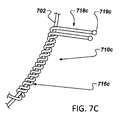
図7A〜7Eは、それぞれ固定アンカー例710a〜710eの図である。固定アンカー例710a〜710eの各々は、1本又はそれ以上の固定アンカーワイヤを含み、アンカーワイヤは概ね球形またはボール型端部要素719を含む。アンカー710a、710b、710c、710d及び710eの各々は、マイクロコイルアンカーと見なすことができ、各々、体組織に非外傷的に係止して摩擦、圧力又はもつれによって器具を所定の場所に固定するように作られたボール型端部719又は概ね球形の端部材を含む1つ又はそれ以上受動的アンカー部718を含む。いくつかの実施例において、ボール型端部719は、レーザー溶接によって固定アンカーワイヤの端部に形成できる。ボール型端部719は、固定を与えて、いくつかの実装において、穿孔又は心膜滲出の可能性を減少できる。概略的に、ボール型端部719又は本出願において論じるその他の受動的アンカー特徴部は、いくつかの実装において鋭い縁を持ついくつかの能動的アンカー要素に比べて送達鞘の内面において生じる摩擦が小さく、いくつかの事例において、送達系に対する粒子化(particulation)を減少できる。
7A to 7E are diagrams of fixed anchor examples 710a to 710e, respectively. Each of the fixed anchor examples 710a-710e includes one or more fixed anchor wires, the anchor wire comprising a generally spherical or ball-shaped end element 719. Each of the
いくつかの実施形態において、ボール型端部719の直径は、フレームアンカーワイヤの直径の約2倍である。いくつかの実施例において、ボール型端部719の直径は、例えば、約1x(丸いワイヤ端部の場合)から約2x又は2.5xフレームアンカーワイヤの直径までの範囲であり、直径は、約1.5xフレームアンカーワイヤの直径又は約1.6、1.7、1.8又は1.9xフレームアンカーワイヤの直径である。ボール型端部は、例えばフレームアンカーワイヤの端部にレーザーパルスを当てることによって生成できる。例えば、いくつかの実施形態において、球形部材又はボール型端部は、精密レーザー溶接技術を用いて(例えば、Nd:YAGレーザーを用いて)フレームアンカーワイヤの端部に直接形成できる。 In some embodiments, the diameter of the ball-shaped end 719 is about twice the diameter of the frame anchor wire. In some embodiments, the diameter of the ball-shaped end 719 ranges from, for example, about 1x (for round wire ends) to about 2x or 2.5x, the diameter of the frame anchor wire, and the diameter is about. The diameter of the 1.5x frame anchor wire or about 1.6, 1.7, 1.8 or 1.9x the diameter of the frame anchor wire. The ball-shaped end can be generated, for example, by applying a laser pulse to the end of the frame anchor wire. For example, in some embodiments, the spherical member or ball-shaped end can be formed directly at the end of the frame anchor wire using precision laser welding techniques (eg, using an Nd: YAG laser).
アンカー710a、710b、710c、710d及び710eの各々は、ワイヤなど、1つ又は2つの長尺部材を含む。固定アンカーワイヤの枠接合部716の各々は、医療器具の対応する枠形成長尺部材702の周りに巻き付けられる。いくつかの実装において、枠接合部716及び/又は長尺部材702の対応する部分はFEP又は別の適切な接着剤でコーティングして、固定アンカー710の枠接合部を枠の長尺部材702に固定でき、いくつかの実装において、ワイヤは、FEP又は他の接着剤なしに長尺部材702の周りに巻き付けられる。いくつかの実施例において、アンカーは、長尺部材に溶接又ははんだ付けできる。
Each of the
図7Aを参照すると、固定アンカー710aは、単一の固定アンカーワイヤを含み、その一部は枠接合部716aを形成し、一部はアンカー部718aを形成し、アンカー部はボール型端部719aを含む。それぞれ図7B〜7Eアンカーの710b〜710eは、各々、2本のフレームアンカーワイヤを含み、各々、ボール型端部を持つ2つのフレームアンカー部718を含む。図7B、7C及び7Dから分かるように、2つのアンカー部718の長手方向の間隔は変動可能である。即ち、アンカー710bの2つのアンカー部718bは概ね相互に接触しており、いくつかの事例においては一緒に溶接又ははんだ付けして(例えば、ボール型端部719bにおいて及び/又はアンカー部718bの別の部分において)、アンカー710に付加的剛直性を与えることができる。アンカー710cの2つのアンカー部718cは長尺部材702に沿って短い長手方向の間隔で相互に離間して、フレームアンカー部718cの間隔を概ね密にする。アンカー710dの2つのアンカー部718dは、長尺部材702に沿ってより大きい長手方向の間隔で離間する。他の間隔も同様に選択できる。アンカー部718b、718c及び718dは、相互に概ね平行に延びるが、図7Eのアンカー710eにおいては、2つのアンカー部718eはその間に角度を含むことができる。
Referring to FIG. 7A, the fixed
図8A〜8Cは、それぞれ閉塞器具例800a〜800cの側面図であり、様々なアンカー設置位置例を図解する。アンカー810は、概ね本出願において論じるアンカーのいずれをも代表できる。図8Aの閉塞器具800aは、器具の近位領域812において、器具の近位ディスクに配置されたアンカー810aを含む。いくつかの実施例において、アンカー810aは、例えば近位ディスクの近位面に又は近位面の周囲に配置できる。アンカー810aの配置は、いくつかの実装においてLAAの口への固定を容易にできる。アンカーが枠から延びる角度は、要望次第で変えられる。
8A to 8C are side views of the closing device examples 800a to 800c, respectively, and illustrate various anchor installation position examples. Anchor 810 can represent generally any of the anchors discussed in this application. The
図8Bの器具800bは、器具の遠位領域814内において器具の支持部に配置されたアンカー810bを示す。アンカー810bの設置位置は、いくつかの実装において、LAAの中へのより深い固定又は脈管を閉塞する応用において脈管の中へより深い固定を容易にできる。図8Cの器具800cは、器具の遠位領域814において器具の支持部の遠位端付近に配置されたアンカー810cを含む。アンカー810cの設置位置は、器具の遠位端が最初に留置される実装において器具800cが送達系から留置されるとき留置部位における早期の固定を容易にする。これによって、器具を留置するとき所望の位置に器具を保持する可能性を増大し、正確度を改良し、器具が移動する可能性を減少する。アンカー810cの設置位置は、いくつかの実装においてLAAの中へ更に深い固定又は脈管を閉塞する応用において脈管の中へ更に深い固定も容易にできる。アンカー810cは、器具の枠に付加的剛直性も与えることができる。
閉塞器具800a、800b及び800cから分かるように、器具の枠は、概ね、「ベル」形、円筒形、テーパー形状またはその他の適切なシェイプフィリング形状(shape-filling shape)などの形状を持つことができる。近位ディスクは、いくつかの実施形態において、概ね平面形状を持つことができ、いくつかの実施形態においては、凹面形状又は凸面形状を持つことができる。即ち、近位ディスクは、遠位方向に又は近位方向に「カップ状」とすることができる。いくつかの実施例において、アイレットから器具のリムまで放射状に延びるワイヤ部は、概ね「S字形」又はその他の適切なループ形状などのループ形状を含むことができる。近位ディスクは、LAAの口をシールでき、LAAから左心房への流体又は物質の漏出を防止できる。
As can be seen from the
図8D及び8Eは、それぞれ閉塞器具例800d及び800eの近位端面図であり、様々なアンカー設置位置例を図解する。アンカー810は、概ね本出願において論じるアンカーのいずれも代表できる。図8Dの器具800dは、器具の近位ディスクに配置されたアンカー810dを含み、近位ディスクの花弁1つに1つのアンカー810dを含む。図8Eの器具800eは、器具の近位ディスクに配置されたアンカー810eを含み、近位ディスクの花弁1つに2つのアンカー810eを含む。他の実施例において、ディスクの花弁1つに3つ以上のアンカー810を含むことができる。いくつかの実施例において、ディスクの1つ又はそれ以上の花弁はアンカー810を含まない。
8D and 8E are proximal end views of the occlusion device examples 800d and 800e, respectively, and illustrate various anchor installation position examples. Anchor 810 is generally representative of any of the anchors discussed in this application. The
概略的に、アンカーの相互の間隔又は器具枠の特徴部に対するアンカーの間隔は、均等であっても不均等であっても良い。概略的に、本出願において説明するアンカー及び特に本出願において説明するアンカーの枠接合部は、枠接合部が接合される枠形成長尺部材の曲り部を横切って配置できる。この種の曲り部は、例えば閉塞部又は支持部など、器具の任意の部分に配置できる。 In general, the spacing between the anchors or the spacing between the anchors relative to the feature of the instrument frame may be uniform or uneven. In general, the frame joints of the anchors described in this application and in particular the anchors described in this application can be arranged across the bends of the frame-forming elongated members to which the frame joints are joined. This type of bend can be placed at any part of the instrument, such as a block or support.
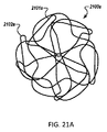
図9は、逆転アイレット906を含む閉塞器具枠例900の側面図である。この実施例において、遠位アイレット906は、逆転しており、器具の枠部の遠位端と近位アイレット908との間に配置される。例えば、逆転遠位アイレット906は、器具の枠の遠位へ突出せず、器具900の枠の支持部によって形成された空間内に位置付けられる。逆転遠位アイレット906は、いくつかの実装において、遠位に延びるアイレットに比べて、例えばLAAを閉塞する応用において遠位ディスクが心臓の壁と境界を接する心内膜に対する圧力又は力を減少または排除できる。これによって、例えば心膜又はその他の周囲心臓構造に対する摩耗を減少または排除できる。概略的に、逆転アイレット906は、本出願において論じる枠又は器具のいずれかに関して論じた遠位アイレットのいずれにも取って代わることができる。いくつかの実施例において、逆転アイレットは、近位方向へ延びる近位アイレットに取って代わるために使用できる。逆転近位アイレット(図示せず)は、器具の枠の近位に突出せず、器具の枠によって形成された空間内に位置付けられる。逆転近位アイレットは、例えば器具の中心領域向きである。逆転近位アイレットを含む実施形態において、概ね平面状の近位閉塞ディスクを越える近位方向のアイレット延長部を減少または排除することによって、血流の妨害を最小化又は排除できる。これは、例えば血栓形成の源を排除する作用を持つ。
FIG. 9 is a side view of the closing device frame example 900 including the reversing
アイレット906などの逆転アイレットを含む器具は、逆転アイレットを含まない器具とは異なる巻き方ができる。例えば、逆転遠位アイレットの場合、器具の枠形成長尺要素902は、上向き又は近位方向ではなく下向き又は遠位方向に逆転アイレットを巻回するために使用できる。即ち、長尺部材902の第1端部をロッド又は心棒の周りに巻き付けることができ、長尺部材の端部は、まず逆転アイレット906の近位端903を形成する。逆転アイレット906の所望の長さに達したら、長尺部材は、逆転アイレット906の遠位端905から広げることができる。このようにして、長尺部材902は、いくつかの実装において、逆転アイレット906の最遠位端905から延びることができ、近位アイレットの近位端903からは延びない。
An instrument containing a reversing eyelet, such as the
枠900は、2つのアイレットを含み、ここで、アイレット906は、下向き又は遠位方向へ巻回され、アイレット908は上向きに又は近位方向へ巻回される。従って、アイレット906と908は、反対方向へ巻回される。また、逆転アイレット906は、例えば枠の内部空間の外部に巻いた後に内部空間へ押し込む必要なく、アイレットが枠の内部空間を占めるように巻回される。
The
枠900を展開又は伸張するとき、逆転アイレット906は、伝統的な外部遠位アイレットとは逆に、圧縮状態に維持される(加えられた力によって伸張されることなく)。伝統的外部遠位アイレットの場合、外部に延びる遠位アイレットの場合、枠を伸張するとき、器具の伸張に係る力は、伝統的外部遠位アイレットを伸張するようにも作用する。いくつかの実装において、この事は、例えば器具の無欠性を助長できる。
When deploying or stretching the
逆転アイレット906が形成された後、第1領域(例えば、遠位領域)の1つ又はそれ以上の特徴部を巻回し、第2領域(例えば、近位領域)の1つ又はそれ以上の特徴部を巻回し、第2アイレット(例えば、近位アイレット)を巻回できる。いくつかの実施例において、第3領域(例えば、移行領域)の1つ又は以上の特徴部は、付加的巻回ステップを含み、上記の実施例において、付加的巻回ステップは、第1領域の特徴部の巻回ステップ後に実施できる。概略的に、逆転遠位アイレットを含む器具の巻回ステップは、逆転アイレットが上向き又は近位方向ではなく下向きに又は遠位方向へ巻回されることを除いて、逆転遠位アイレットを含まない器具の場合のステップと同様とすることができる。言い換えると、逆転アイレットは、器具の内部から離れる方向へ巻回できる。
After the
図17は、2つの逆転アイレット1706及び1708を含む閉塞器具枠例1700の図である。この実施例において、遠位アイレット1708及び近位近位アイレット1706の両方は逆転している。遠位アイレット1708及び近位アイレット1706の各々は、枠1700の枠形成長尺部材1702によって形成された空間内に配置される。遠位アイレット1708及び近位アイレット1706の各々は、器具の枠部の遠位端と器具の枠部の近位端との間に配置される。例えば、逆転遠位アイレット1708は、器具の枠の遠位へ突出せず、器具1700の枠の支持部によって形成された空間内に位置付けられる。同様に、逆転近位アイレット1706は、器具の枠の近位へ突出せず、器具1700の枠の閉塞部によって形成された空間内に位置付けられる。長尺部材1702は、いくつかの実装によれば、逆転アイレット1708の最遠位端1705から延び、逆転アイレット1708の近位端1703からは延びない。同様に、長尺部材1702は、いくつかの実装によれば、逆転近位アイレット1706の最近位端1707から逆転近位アイレットへ進入し、近位アイレット1706の遠位端1709からは進入しない。枠1700の逆転アイレットは、例えば枠900を参照して上に説明したのと同じ又は同様の利点を与えることができる。
FIG. 17 is a diagram of an obstruction device frame example 1700 including two
枠1700は、近位アイレット1706を下向き又は遠位方向へ巻回できることを除いて(枠900の非逆転近位アイレット908は上向き又は近位方向へ巻回した)、枠900と同様に巻回できる。従って、アイレット1706と1708は、同じ方向へ巻回される。また、逆転アイレット1706及び1708の各々は、例えば枠の内部空間の外側に巻回した後内部空間に押し込む必要なく枠の内部空間を占めるように巻回される。枠1700を展開又は伸張するとき、逆転アイレット1706及び1708は、圧縮状態に維持され(与えられた力によって伸張されることなく)、これは、例えば器具の無欠性を改良できる。
The
図10Aは、単一のアイレット1001を含む閉塞器具枠例1000の斜視図である。アイレット1001は、いくつかの実装において近位アイレットを表し、器具1000は、遠位アイレットを含まない。この器具の実装は、例えば遠位ディスクと心臓組織との間の境界面における組織接触圧の減少を含めて、逆転遠位アイレットを採用する器具と同じ潜在的利点を享受できる。枠1000は、この実施例において3本ワイヤ器具であり、6つのワイヤ端(各ワイヤの両端)は全て単一アイレット1001において終端する。即ち、全ての枠形成長尺部材1002のワイヤ端は、単一のアイレット1001において終端する。他の実施例において、3本より多い又は少ないワイヤを含む枠は単一のアイレットを含み、全てのワイヤ端が単一のアイレットで終端できる。
FIG. 10A is a perspective view of an obstruction device frame example 1000 including a
器具1000は、本出願において説明する他の器具と異なる巻き方ができる。例えば、長尺部材1002の各々の略中点は、集合点(aggregation point)1003において垂直に整列でき、長尺部材は、相互に約120度離間する。第1領域(例えば、遠位領域)の特徴部を巻回でき、ここで、単一の長尺部材は第1領域において2つの特徴部(長尺部材の略中点の両側において)を形成できる。次に第2領域の特徴部を巻回でき、ここでも各長尺部材は第2領域において2つの特徴部を形成できる。次に、各長尺部材の両端部をバーまたは心棒の周りに巻き付けて、単一アイレット1001を形成できる。
The
図10Bの枠1020は、枠1000と同様であるが、長尺部材1002が係止部材1021を貫通できるようにしながら集合点1003(図10A)において又はその付近で枠の長尺部材1002と係止できる係止部材1021を含む。係止部材1021は、いくつかの実装において枠に安定性を与えることができ、かつ送達系の構成要素の接合点を与えることができ、それにより、留置時に器具をより良く制御できるようにする。概略的に、係止部材1021は、長尺部材1002を挟むことができ、長尺部材は、例えば係止点において仮溶接(tack-weld)又ははんだ付けできる。係止部材1021は、また、いくつかの実装において、係止部材1021における長尺部材の回動を助長できる。
The
図10C及び10Dは、一緒に図10Bの係止部材1021を構成するそれぞれ構成要素例1030及び1032の図である。上述のように、器具1000は、3本ワイヤ器具であり、構成要素1030は、第1チャネル1034、第2チャネル1036及び第3チャネル1038を含む。第1チャネル1034は、3本ワイヤ器具1000の第1ワイヤの一部を収容でき、第2チャネル1036は3本ワイヤ器具1000の第2ワイヤの一部を収容でき、第3チャネル1038は3本ワイヤ器具1000の第3ワイヤの一部を収容できる。図10Cから分かるように、3本のチャネル1034、1036及び1038は、構成要素1030において異なる深さで配列される。第1チャネル1034は、構成要素1030内において比較的深い。第3チャネルは構成要素1030内において比較的浅く、第2チャネル1036は、第1チャネル1034と第3チャネル1038の深さの間の深さである。3本のワイヤ1002の一部が構成要素1030のそれぞれのチャネル1034、1036及び1038に配置された後、構成要素1032が構成要素1030の上に置かれ、構成要素1030と1032は一緒に溶接(例えば仮溶接)するか、又は他の様式で相互に接合できる。図10Dから分かるように、構成要素1032は、1つ又はそれ以上の整列部材1040を含み、整列部材は、構成要素1030のチャネルと整列できる。構成要素1030及び1032は、ワイヤ1002を係止でき、異なる高さでワイヤ1002を重ねられるようにするので、ワイヤ1002間の干渉又はワイヤ1002のもつれを防止又は最小化できる。構成要素1030は、接続機構1042を含み、いくつかの実装において、これに送達系の構成要素を分離可能に接合できる。いくつかの実施形態において、接続機構1042は、構成要素1030の底部に配置できる。別の実施形態において、構成要素1030及び1032を結合して、単一の構成要素にできる。いくつかの実施形態において、構成要素1030は、任意の適切な本数のワイヤ有する枠を収容できるように、もっと少ない(例えば2つ)又はもっと多い(例えば4、5、6、7、8、9、10又はそれ以上)のチャネルを含むことができる。
10C and 10D are diagrams of component examples 1030 and 1032, which together constitute the locking
図11A及び11Bは、各々遠位アイレットの代わりにそれぞれハブ機構1106a及び1106bを含む閉塞器具枠例1100a及び1100bの部分の図である。例えば、ハブ機構1106は、閉塞器具枠の伝統的遠位アイレットに取って代わることができる。図11Aを参照すると、ハブ機構1106aは、概ねドーナツ形の部材1107aを含み、これを通過させて枠1100aの長尺部材1102aをループ状にする。例えば、枠1100aは、6つの長尺部材1102aを含み、各長尺部材1102aは、ドーナツ形部材1107aの内部空間を2回通過する。枠1100aを組み立てる際、長尺部材1102aの各々の第1端部はドーナツ形部材1107aによって形成された内部空間を通過し、その後ドーナッツ形部材の外面の周りにループを形成し、内部空間を2度目に通過する。図11Aから分かるように、各長尺部材1102aの第1部分1105a及び第2部分1105bは、ドーナッツ形部材1107aから延びる。所与の長尺部材1102aの第1部分1105a及び第2部分1105bは、枠の第1領域(例えば、遠位領域)において特徴部を生成するように巻回され、次に、枠の第2領域において特徴部を生成するように巻回できる。第1部分1105a及び第2部分1105bの各々の端部は、その後バーまたは心棒の周りに巻き付けて、アイレット(例えば、近位アイレット)を形成できる。
11A and 11B are views of the portion of the occlusion device frame examples 1100a and 1100b including the
長尺部材1102aは、ドーナツ形部材1107aの上又はその周りで回動でき、それによって、例えば送達系への器具の装填及び/又は送達系からの器具の留置のために枠1100aの伸縮を容易にできる。例えば、長尺部材1102aの各々は、概ねドーナッツ形部材1107aの周りを回動できる。
The
いくつかの実装において、各長尺部材1102aは、ドーナッツ形部材の内部空間を1回通過できる。いくつかの実装において、各長尺部材1102aは、ドーナッツ形部材の内部空間を3回通過できる。いくつかの実装において、異なる長尺部材1102aは、ドーナッツ形部材1107aの内部空間を異なる回数通過できる(例えば、長尺部材の半分は1回通過し、残りの半分は2回通過する)。
In some implementations, each
いくつかの実施例において、ドーナッツ形部材は、丸いプロフィルを有する。例えば、いくつかの実施形態において、ドーナッツ形部材の断面は円形、卵形又は楕円形である。ドーナッツ形部材が楕円形の断面形状を有する実装において、楕円形の長径は、例えば器具全体に対して概ね半径方向又は概ね長手方向を向くことができる。いくつかの実施例において、ドーナッツ形部材1107aは、溝、畝又はスロットを含むことができ、長尺部材1102aは、概ね溝、畝又はスロット内に位置付けることができる。
In some embodiments, the donut-shaped member has a round profile. For example, in some embodiments, the cross section of the donut-shaped member is circular, oval or oval. In an implementation in which the donut-shaped member has an elliptical cross-sectional shape, the elliptical major axis can be oriented approximately radially or approximately longitudinally, for example, with respect to the entire instrument. In some embodiments, the donut-shaped
いくつかの実装において、ドーナッツ形部材は、長尺部材がドーナッツ形部材の丸いプロフィル部分上を設定された量だけ回転して、ドーナッツ形部材の平坦プロフィル部分に接触することによってそれ以上の回転を防止されるように、部分的に丸くかつ部分的に平坦なプロフィルを持つ。このようにして、回動の角度又は量を制御できる。 In some implementations, the donut-shaped member is rotated further by a set amount of rotation over the round profile portion of the donut-shaped member and in contact with the flat profile portion of the donut-shaped member. Has a partially rounded and partially flat profile to prevent it. In this way, the angle or amount of rotation can be controlled.
枠1100aは、器具の特徴部を作るために2つのワイヤ部分(1105a及び1105b)が使用されるので、2本糸式枠(two-filar frame)と見なすことができる。即ち、所定の特徴部(例えば、近位ディスクの花弁又は枠の遠位領域の支持機構)のために、第1及び第2長尺ワイヤ部分1105a及び1105bを用いて、特徴部が形成される。いくつかの実装において、2本糸式枠は、例えば、優れた耐疲労性を提供できる。更に、枠1100aは、第1及び第2長尺ワイヤ部分1105a及び1105bがほぼ相互に平行に走るので、平行2本糸式枠と見なすことができる。
The
いくつかの実装において、各長尺部材1102aを、ドーナッツ形部材1107aの内部を1回通過させ、その後、上述のように器具を巻回する前に長尺部材の第1部分1105aと第2部分1105bを交差させることによって1回又はそれ以上(例えば、1回、2回、3回又はそれ以上)捻る。いくつかの実装において、1回又はそれ以上の捻りは、器具に沿って様々な点で(例えばドーナツ形部材1107aにおいて、器具の遠位領域において、器具の移動領域において、又は器具の近位領域において)実施する。
In some implementations, each
ドーナッツ形部材1107aの内径は、ドーナッツ形部材1107aの内部領域を通過する長尺部材の様々な部分が概ね内部空間内にぴったりと位置付けられるように選択できる。例えば、ドーナッツ形部材の内径は、ワイヤ部分がドーナッツ形部材の特定のエリアにおいて集まったり束状になったりせずに又はドーナッツ形部材の特定のエリアにおいて分離して孤立することなくドーナッツ形部材の周りに概ね均等な間隔で留まるように、選択できる。
The inner diameter of the donut-shaped
いくつかの実施形態において、ドーナッツ形部材1107aは、1つ又はそれ以上の貫通孔を含む。長尺部材1102aは、例えば1つ又はそれ以上の貫通孔を個別に通過でき、貫通孔は、特定の向きで長尺部材の一部をロックするのを容易にする。
In some embodiments, the donut-shaped
いくつかの実装において、捻ったワイヤの対を長尺部材1102aの1つ又はそれ以上の代わりとすることができる。捻った対の一方のワイヤは、器具の枠の経路を追跡するために使用でき、捻った対の他方のワイヤは、器具のための1つ又はそれ以上の固定又はアンカー特徴部を生成するために使用できる。例えば、固定又はアンカー特徴部は、捻った対のワイヤの一方のワイヤを用いて、器具の遠位領域に生成できる。いくつかの実施例において、固定又はアンカー特徴部を作るために使用される捻った対のワイヤは、固定又はアンカー特徴部において終端し、別の実施例において、固定又はアンカー特徴部を形成した後に枠の経路において捻った対の他方のワイヤに再接合できる。
In some implementations, a pair of twisted wires can replace one or more of the
図11Bは、遠位アイレットに取って代わるハブ機構1106bを持つ枠1100bの別の実施例を示す。又は、ハブ機構1106bは、近位アイレットに取って代わることができる。ハブ機構1106bは、概ねドーナッツ形の部材1107bを含み、これを通過して枠1100bの長尺部材1102bはループ状になる。
FIG. 11B shows another embodiment of a
図11Cは、別のハブ機構例1120bの図である。概略的に、ハブ機構1120は、本出願において論じる器具例のいずれにおいてもアイレット(例えば、遠位アイレット又は近位アイレット)に取って代わることができる。ハブ機構例1120は、ハブ機構1120の側壁124に傾斜した又は角度を成すスロット1122(又は開口部)を含む。傾斜スロット1122は、側壁1124の外面から側壁1124の内面まで通過して、スロットが側壁と直交しないような角度で側壁を貫通する。いくつかの実施例において、スロット1122は、側壁1124に対して約45度の角度で又は他の適切な角度(例えば、約30、35、40、50、55、60、65、70又は75度)で側壁1124を貫通できる。下で更に説明するように、傾斜スロット1122は、ハブ機構1120に対して特定の向きで枠のワイヤを配置するために使用される。ハブ機構1120は、6本ワイヤ器具に合うサイズを持つが、他の実施例においては、より多く(例えば、7、8、9、10、11、12又はそれ以上)の又はより少ない(例えば、5、4、3、2)本数のワイヤを有する器具に合うサイズを持つことが可能である。
FIG. 11C is a diagram of another hub mechanism example 1120b. In general, the
図11D及び11Eは、図11Cのハブ機構例1120を含む枠例1130の一部の図である。図11Dから分かるように、枠1130のワイヤ1126は、それぞれハブ機構1120の内部空間から傾斜スロット1122を通過してハブ機構1120の外部へ至り、その後側壁1124の周りに及び側壁1124の長手方向反対の端の周りに巻き付けられる。図示する実施例において、ワイヤ1126は、溶接工程又はその他の加熱工程によってワイヤ1126の端部に形成される又はワイヤの端部に接合されるボール型端部1128を持つことができる。ボール型端部1128は、ワイヤの端部が傾斜スロット1122から引き抜かれるのを防止し、ワイヤ1126をハブ機構1120に連結するように、傾斜スロット1122より大きいサイズを持つことができる。
11D and 11E are a partial view of frame example 1130 including hub mechanism example 1120 of FIG. 11C. As can be seen from FIG. 11D, the
図11Fは、別のハブ機構例1140の断面図である。概略的に、ハブ機構1140は、本出願において論じる器具例のいずれにおいても、アイレット(例えば、遠位アイレット又は近位アイレット)に取って代わることができる。ハブ機構1140は、外側要素1142と、外側要素1142内部に配置されこれに接合される内側要素1144とを含む。図11Gは、内側要素1133の斜視図である。この実施例において、内側要素1144は、内側要素1144の保持部材1148にスロット1146を含む。ベース部材1150は、内側要素1144の一端に配置される。
FIG. 11F is a cross-sectional view of another hub mechanism example 1140. In general,
図11Fから分かるように、ワイヤ1152のボール型端部1154は、内側要素1144のベース部材1150と保持部材1148との間に配置され、ワイヤ1152は、内側要素1144のスロット1146を通過する。次に、ワイヤ1152は、外側要素1142の内側領域から外側要素1142の側壁を乗り越える。図11Hは、ハブ機構1140の端面図である(単純化のために、6本の枠ワイヤ1152のうち3本のみ図示する)。図示する実施例において、内側要素1144は、保持部材1148が外側要素の縁から所定の間隔を置いて、ワイヤ1152が外側要素1142の内部から出る前にある程度のひずみ解放を与えられるように、外側要素1142内部に配置される。他の実施形態において、保持部材1148は、外側要素1142の縁と同一平面上とすることができる。内側要素1144は、例えば送達系の構成要素と分離可能に連結するために使用できる接続機構1154を形成できる。図11F〜11Hの実施例は、6本ワイヤ器具用のハブ機構1140を示すが、もっと多い(例えば、7、8、9、10、11,12又はそれ以上)又はもっと少ない(例えば、5、4、3、2)本数のワイヤを持つ器具用のサイズを持つことができる。
As can be seen from FIG. 11F, the ball-shaped
図11I及び11Jは、別のハブ機構例1160の図である。ハブ機構1160は、ワイヤ1162のボール型端部がハブ機構の本体1172によって形成された領域1164内に収容される点で、ハブ機構1140と同様である。特に、ワイヤ1162のボール型端部は、ハブ機構1160のストッパ面1166とハブ機構のキャップ1168との間に収容され、キャップ1168は、ワイヤ1162が通過する開口部1170を形成する。キャップ1168は、ハブ機構1160の本体に溶接又はその他の様式で接合できる。ワイヤ1162は、その後ハブ機構1160の本体1172の周りに1回又はそれ以上巻き付けられる。ひずみ解放は、いくつかの実装において、ワイヤ1162をハブ機構の本体1172の周りに巻き付けることによって与えることができる。いくつかの実施例において、ハブ機構の本体1172は、例えばワイヤ1162を案内するために本体1172の外面に溝又はチャネルを含むことができる。図11Iの実施例は、6本ワイヤ器具のためのハブ機構1160を示すが、別のハブ機構は、もっと多い(例えば、7、8、9、10、11,12又はそれ以上)又はもっと少ない(例えば、5、4、3、2)本数のワイヤを持つ器具用のサイズを持つことができる。図11Kは、ハブ機構1140及び1160と同様の別のハブ機構例1175の断面図であるが、この場合、ボール型端部を持つワイヤは、ボール形ハブ機構内に捕捉される。
11I and 11J are diagrams of another hub mechanism example 1160. The
図11Lは、別のハブ機構例1180の斜視図である。図示する実施例において、ハブ機構1180は、概ね環形の本体部1182を含む。本体部は、環形本体部1182の壁を長手方向に通過して配置される12の開口部1184を含む。いくつかの実施例において、ハブ機構1180は、6本のワイヤを含む2本糸器具に使用でき、いくつかの実施形態において、ハブ機構1180は、12本のワイヤを含む単一糸器具に使用できる。
FIG. 11L is a perspective view of another hub mechanism example 1180. In the illustrated embodiment, the
開口部1184は、いくつかの実施例において、本体部1180の壁を貫通してレーザーカットすることができる。いくつかの実施例において、開口部1180のいくつかは、第1直径を有し、開口部1180のいくつかは第2の異なる直径を持つことができる。いくつかの実施例において、開口部1180は、全て同じ直径を有する。概略的に、開口部1180は、本体部材1182の円周の周りに等間隔に配置できる。
The
図11Lは、6本のワイヤがハブ機構1180に使用され、6本のワイヤの各々がそれぞれハブ機構1180の第1開口部1184を第一長手方向へ通過し、その後第2開口部1184を反対の長手方向にハブ機構1180を通過して戻る。ここで、第2開口部1184は第1開口部1184に隣接せず、第1開口部から開口部1つ分オフセットする。例えば、12の開口部に本体部1182の周りで右回りに連続番号1〜12を付ける場合、第一ワイヤは、開口部1及び3を(異なる方向へ)通過し、第2ワイヤは、開口部2及び4を(異なる方向へ)通過し、第3ワイヤは、開口部5及び7を(異なる方向へ)通過し、第4ワイヤは、開口部6及び8を(異なる方向へ)通過し、第5ワイヤは開口部9及び11を(異なる方向へ)通過し、第6ワイヤは開口部10及び12を(異なる方向へ)通過する。いくつかの実施例において、ワイヤのいくつかは異なるサイズを持つことができる。例えば、第1、第3及び第5ワイヤは第1直径(例えば、0.0229cm(0.009インチ))を持ち、第2、第4及び第6ワイヤは第2直径(例えば、0.0178cm(0.007インチ))を持つことができる。これによって、例えば、器具の特定の特徴部を第1直径のワイヤによって形成し、器具の他の特徴部を第2直径のワイヤによって形成できる。いくつかの実施例において、器具の構造的特徴部は、大きいほうのワイヤで生成し、例えば器具のアンカー特徴部は、小さい方のワイヤで生成できる。
In FIG. 11L, six wires are used in the
図11Mは、様々なハブ要素例1190、1192、1194及び1196の図である。ハブ要素1190〜1196の各々は、概ね環形の本体を有し、環形本体の壁を長手方向に貫通する開口部を形成する。ハブ要素1190及び1192は、非円形形状を持つ中央内腔を含み、ハブ要素1194及び1196は、円形形状を有する中央開口を含む。ハブ要素1190及び1192は、例えば中央内腔が非円形なので、「キー式」要素と見なすことができる。中央内腔は、送達系の構成要素と連結することによって、器具の留置、器具の操作、及び留置時の器具の整列の維持に使用できる。
FIG. 11M is a diagram of various hub element examples 1190, 1192, 1194 and 1196. Each of the
様々な実施例において、ハブ要素1190〜1196は、様々な高さ又は長手長さを持つことができ、いくつかの事例において、2つ又はそれ以上のハブ要素は上下に積重ねできる。いくつかの実施例において、ボール型端部を有するワイヤは、図11M(又は図11L)のハブ要素と連結できる。ここで、ワイヤは、ハブ要素の開口部を通過して、ボール型端部は、ワイヤの端部が開口部を通過するのを防止する。図11Nは、図11M(又は図11L)のハブ要素の様々な応用の図であり、ボール型端部を持つワイヤがハブ要素によってどのように終端できるかの実施例を示す。ボールは、ワイヤ端部を溶融することによって又はワイヤ端部を処理する他の手段によって形成できる。
In various embodiments, the
図12A及び12Bは、それぞれ閉塞器具枠例1200の斜視図及び近位端面図である。枠1200は、符号1202a、1202b、1202c、1202d、1202e及び1202fが付けられた6つの長尺部材1202を含む。6つの長尺部材1202a〜1202fの各々の第1端部は近位アイレット1208を形成し、長尺部材1202a〜1202fの各々の第2端部は、遠位アイレット1206を形成する。アイレット1208と1206との間には、この実施例において、近位領域および遠位領域の特徴部がある。長尺部材1202aを参照すると、長尺部材1202aは、近位アイレット1208から延びて、近位特徴部1212aを形成する。近位特徴部1212aは、概略的に器具の「花弁」と呼ぶことができ、概ね器具の近位領域に配置できる。器具の移行領域を通過した後、長尺部材1202aは遠位特徴部1214aを形成する。遠位特徴部は、概ね器具の遠位領域に配置できる。図12Bの近位端面図から分かるように、所与の長尺部材1202aの場合、長尺部材1202aによって形成された遠位特徴部1214aは、同じ長尺部材1202aによって形成された近位特徴部1212aと長手方向に整列する。図12Bから分かるように、長尺部材の近位アイレットからの退出特徴(例えば、退出位置及び退出角度)及び遠位アイレットへの進入特徴(例えば、進入位置及び進入角度)を考慮できる。例えば、長尺部材1202cは、約12時の位置において垂直から約30度の角度で近位アイレットから出て、約12時の位置において、垂直から約90度の角度で遠位アイレットへ入る。近位アイレットから長尺部材が出る角度と遠位アイレットへ入る角度を±約90度以内に整列させることによって、器具の枠は、例えばより捻りに関してバランスの良い状態が得られる。いくつかの事例において、器具が装填されて潰れ又は伸張又は拘束形態となり、その後留置されて拡張形態に拡張できるようになったとき、1つの体レットの他のアイレットに対するトルク傾向を小さくできる。
12A and 12B are a perspective view and a proximal end view of the closing device frame example 1200, respectively. The
同様に、長尺部材1202b〜1202fの各々は、近位アイレット1208から延びて、器具の近位領域においてそれぞれの近位特徴部を形成し、器具の移行領域を通過して、器具の遠位領域においてそれぞれの遠位特徴部を形成する。図12Bから分かるように、6つの近位特徴部又は花弁は、近位アイレット1208の周りで概ね等間隔に配置され、6つの近位特徴部は、集合して枠1200の閉塞機構を形成する(例えば、枠又は枠の一部が膜状被覆によって被覆されたとき)。例えば枠の近位特徴部が膜状被覆によって被覆されたとき、閉塞機構は、LAA又は患者体内のその他の空間、孔、欠損、開口部、付属器、脈管又は導管を閉塞するために使用できる。同様に、6つの遠位特徴部は、遠位アイレット1206の周りで概ね等間隔に配置され、合せて6つの遠位特徴部は、枠1200の支持機構を形成する。いくつかの実施例において、遠位特徴部1214(又は近位特徴部1212)の1つ又はそれ以上は、マイクロコイルアンカーを含むか、又は一体化されたアンカー特徴部を含むことができる(下の図14C及び14Dの説明を参照のこと)。
Similarly, each of the
図13A及び13Bは、それぞれ閉塞器具枠例1300の斜視図及び近位端面図である。枠1300は、符号1302a、1302b、1302c、1302d、1302e及び1302fが付けられた6つの長尺部材1302を含む。6つの長尺部材1302a〜1302fの各々の第1端部は近位アイレット1308を形成し、6つの長尺部材1302a〜1302fの各々の第2端部は遠位アイレット1306を形成する。アイレット1308と1306の間には、この実施例においては、近位領域および遠位領域の特徴部がある。長尺部材1302aを参照すると、長尺部材1302aは、近位アイレット1308から延びて、近位特徴部1312aを形成する。近位特徴部1312aは、概略的に器具の「花弁」と呼ぶことができ、概ね器具の近位領域に配置できる。器具の移行領域を通過した後、長尺部材1302aは遠位特徴部1314aを形成する。遠位特徴部は、概ね器具の遠位領域に配置できる。図13Bから分かるように、長尺部材1302aは、約12時の位置において垂直から約20度の角度で近位アイレットから出て、約4時の位置において垂直から約60度の角度で遠位アイレットへ入る。
13A and 13B are a perspective view and a proximal end view of the closing device frame example 1300, respectively. The
同様に、長尺部材1302b〜1302fの各々は、近位アイレット1308から延びて、器具の近位領域においてそれぞれの近位特徴部を形成し、器具の移行領域を通過して、器具の遠位領域においてそれぞれの遠位特徴部を形成する。図13Bから分かるように、6つの近位特徴部又は花弁は、近位アイレット1308の周りで概ね等間隔に配置され、6つの近位特徴部は、集合して枠1300の閉塞機構を形成する(例えば、枠又は枠の一部が膜状被覆によって被覆されたとき)。例えば枠の近位特徴部が膜状被覆によって被覆されたとき、閉塞機構は、LAA又は患者体内のその他の空間、孔、欠損、開口部、付属器、脈管又は導管を閉塞するために使用できる。同様に、6つの遠位特徴部は、遠位アイレット1306の周りで概ね等間隔に配置され、合せて6つの遠位特徴部は、枠1300の支持機構を形成する。
Similarly, each of the
図12A及び12Bに示す枠1200と比較すると、図13A及び13Bに示す枠1300は、概ね「卵形」の遠位特徴部1314を持つのに対して、枠1200は、概略的により円錐形の形状の遠位特徴部1214を有する。枠1300は、枠1200より浅い移行又はウェスト領域(長尺部材が近位特徴部から遠位特徴部へ移行する領域)を含む。枠1200は、より深い移行又はウェスト領域を有する。より深い移行領域を持つ場合、移行領域を通過する長尺部材1202は、アイレット1206及び1208によって形成された枠1200の長手軸1200により接近する。これに対して、移行領域を通過する長尺部材1302は、アイレット1306及び1308によって形成された枠1300の長手軸からより離れる。枠1200のより深い移行又はウェスト領域は、例えば遠位ディスクと近位ディスクとの間を移行するときジグの中心により近くワイヤを巻き付けることによって形成できる。いくつかの実施例において、遠位特徴部1314(又は近位特徴部1312)の1つ又はそれ以上は、マイクロコイルアンカーを含むか、又は一体化されたアンカー特徴部を含むことができる(下の図14C及び14Dの説明を参照のこと)。
Compared to the
図14A及び14Bは、それぞれ閉塞器具枠例1400の斜視図及び近位端面図である。枠1400は、符号1402a、1402b、1402c、1402d、1402e及び1402fが付けられた6つの長尺部材1402を含む。6つの長尺部材1402a〜1402fの各々の第1端部は近位アイレット1408を形成し、長尺部材1402a〜1402fの各々の第2端部は、遠位アイレット1406を形成する。アイレット1408と1406との間には、この実施例において、近位領域および遠位領域の特徴部がある。長尺部材1402aを参照すると、長尺部材1402aは、近位アイレット1408から延びて、近位特徴部1412aを形成する。近位特徴部1412aは、概略的に器具の「花弁」と呼ぶことができ、概ね器具の近位領域に配置できる。器具の移行領域を通過した後、長尺部材1402aは遠位特徴部1414aを形成する。遠位特徴部は、概ね器具の遠位領域に配置できる。図14Bの近位端面図から分かるように、所与の長尺部材1402aの場合、長尺部材1402aによって形成された遠位特徴部1414aは、同じ長尺部材1402aによって形成された近位特徴部1412aから右回り方向にオフセットして形成される。例えば、遠位特徴部1414aは、器具の近位端から見たとき、右回り方向に隣接する長尺部材(この例において長尺部材1402b)によって形成された近位特徴部と概ね長手方向に整列する。図14Bから分かるように、長尺部材1402cは、約12時の位置において垂直から約20度の角度で近位アイレットから出て、約12時の位置において、垂直から約75度の角度で遠位アイレットへ入る。
14A and 14B are a perspective view and a proximal end view of the closing device frame example 1400, respectively. The
更に図14Bから分かるように、所与の長尺部材1402が器具の移行領域を通過するとき、長尺部材1402は、ワイヤの巻回方向を逆転する。例えば、近位特徴部1412aは、概ね右回り方向に巻かれるのに対して、同じ長尺部材1402aによって形成される遠位特徴部1414aは、概ね左回り方向に巻かれる。同じことが他の長尺部材1402〜1402fについても言える。従って、枠1400は、巻回方向が逆転することによって長尺部材による捻りバイアスの量を均衡又は除去できるので、バランスフレームと見なすことができる。例えば、近位特徴部と遠位特徴部との間で巻回方向を逆転することによって、巻き線に関連付けられるトルクのある程度を有利に相殺できる。
Further, as can be seen from FIG. 14B, when a given elongated member 1402 passes through the transition region of the instrument, the elongated member 1402 reverses the winding direction of the wire. For example, the
同様に、長尺部材1402b〜1402fの各々は、近位アイレット1408から延びて、器具の近位領域においてそれぞれの近位特徴部を形成し、器具の移行領域を通過して、器具の遠位領域においてそれぞれの遠位特徴部を形成する。図14Bから分かるように、6つの近位特徴部又は花弁は、近位アイレット1408の周りで概ね等間隔に配置され、6つの近位特徴部は、集合して枠1400の閉塞機構を形成する(例えば、枠又は枠の一部が膜状被覆によって被覆されたとき)。例えば枠の近位特徴部が膜状被覆によって被覆されたとき、閉塞機構は、LAA又は患者体内のその他の空間、孔、欠損、開口部、付属器、脈管又は導管を閉塞するために使用できる。同様に、6つの遠位特徴部は、遠位アイレット1406の周りで概ね等間隔に配置され、6つの遠位特徴部は、集合して枠1400の支持機構を形成する。
Similarly, each of the
図14Cは、別の閉塞器具枠例1420の端面図である。枠1420は、図14A及び14Bの枠1400と同様であり、枠1400が含むのと概ね同じ又は同様の近位特徴部1412及び遠位特徴部1414を含む(近位特徴部1412及び/又は遠位特徴部1414又はその一部が、いくつかの事例において、1本ではなく2本のワイヤで形成できることを除いて)が、更に、枠1420の各遠位特徴部1414に一体化アンカー特徴部1422を含む。この実施例において、一体化アンカー特徴部1422は、非外傷的に組織に接触して留置部位における枠1420の移動を最小化又は防止するように作られたループ又はフィンを含む。いくつかの実施例において、遠位特徴部1414の1つ又はそれ以上(例えば1つおきの遠位特徴部又は3つごとに遠位特徴部)は、一体化アンカー特徴部1422を含まない。一体化アンカー特徴部1422は枠の遠位特徴部1414において示されるが、いくつかの別の実施形態において、一体化アンカー特徴部1422は、枠の1つ又はそれ以上の近位特徴部1412に又は枠の近位及び遠位特徴部の両方に含むことができる。
FIG. 14C is an end view of another closing device frame example 1420. The
様々な実施例において、枠1420(又は枠1420の一部)は、2本糸枠又は枠の一部とすることができる。例えば、各近位特徴部1412は、概ね相互に平行に走る2本のワイヤによって形成でき、各遠位特徴部1414の一部は、2本のワイヤによって形成できる。2本のワイヤの2本目は、一体化アンカー特徴部1422を形成し、その後、戻って2本のワイヤの1本目の経路を概ね追跡する。いくつかの実施例において、第2ワイヤは、一体化アンカー特徴部1422を形成した後終端できる。特に、いくつかの実施例において、12本のワイヤの端部は、遠位アイレットを形成するために使用され、12本のワイヤは6対のワイヤとして広げられて、6つの遠位特徴部1414を形成する。各対の第1ワイヤは、遠位特徴部1414を形成し、各対の第2ワイヤは一体化アンカー特徴部1422を形成する。いくつかの実施例において、ワイヤの対は、一体化アンカー特徴部1422が形成されるところを除いてワイヤ経路に沿った捻りワイヤ対である。いくつかの実施例において各対の第2ワイヤは、一体化アンカー特徴部1422の形成後に終端する。いくつかの実施例において、各対の第2ワイヤは、各対の第1ワイヤと同じ経路を進み、ワイヤは一緒に近位特徴部1412を形成し、近位アイレットにおいて終端する。枠1420を製造する際、巻回ジグは、例えば追加のピン(又はいくつかのツールについては巻回経路)を含むことができ、その周りに、対の第2ワイヤが巻回されて、一体化アンカー特徴部1422を形成する。
In various embodiments, the frame 1420 (or part of the frame 1420) can be a two-thread frame or part of the frame. For example, each proximal feature 1412 can be formed by two wires running approximately parallel to each other, and a portion of each
図14Dは、図14Cの閉塞器具枠1420の端面図であり、枠1420にはシール部材1424が接合されている。図14Dから分かるように、シール部材1424は、本出願において論じる膜状被覆のいずれにも対応し、枠1420に被せて配置できるが、一体化アンカー特徴部1422が、シール部材1424から(例えば、シール部材1424のスリットを通過して)突出できる。
14D is an end view of the
別の一体化アンカー特徴部は、例えば器具の枠を形成しかつ近位特徴部及び遠位特徴部を形成する同じワイヤ又は長尺部材を用いて生成できる。図21A、21B、21C、21D及び21Eは、それぞれ一体化アンカー特徴部2102a〜eを含む他の枠2100a〜eの図である。単純化のために、それぞれ図21A及び21Eの2100a及び2100eについては、それぞれの枠の1つだけのディスクを図示するが、一体化アンカー特徴部2102a、2102eは、例えば2ディスク器具の遠位特徴部あるいは近位特徴部のいずれでも配置できる。一体化アンカー特徴部2102a〜eは、図14C及び14Dを参照して上に説明した2本糸設計と異なり、図21A〜Eの例においては、枠の近位又は遠位特徴部を形成する同じ長尺部材によって形成される。枠2100a、2100b及び2100cは、それぞれ一体化アンカー特徴部2102a、2102b及び2102cを含み、アンカー特徴部は、各々、留置部位において非外傷的に組織に接触して対応する枠の移動を最小化又は防止するように作られた開放ループ又はフィンガ部を含む。枠2100d及び2100eは、それぞれ一体化アンカー特徴部2102d及び2102eを含み、アンカー特徴部は、各々、留置部位において非外傷的に組織に接触し対応する枠の移動を最小化又は防止するように作られた閉鎖ループ又はフィンガ部を含む。アンカー2102eのループ又はフィンガ部については、ワイヤはループのベースにおいて交差して、ワイヤ交差接合部の周りにテザー2104が結ばれて、ワイヤ部を一緒に接合部に保持する。いくつかの実施例において、テザー2104は、延伸PTFE又はPTFEによって構成される。図21A〜Eのいずれにかに図示するアンカー特徴部は、可変的な角度を持つことができ、様々な実施形態において近位又は遠位を向くことができる。例えば、所与の器具の様々なアンカー特徴部は、異なる角度の向きを持つことができる。即ち、1つ又はそれ以上は近位方向を向き、1つ又はそれ以上は遠位方向を向くことができる。アンカー特徴部の長さも、様々な実施形態において変えることができる。枠2100を製造する際、対応する巻回ジグは、例えば追加のピン(又は、いくつかのツールについては巻回経路)を含むことができ、その周りにワイヤが巻回されて、一体化アンカー特徴部を生成する。概略的に、本出願において論じる枠の設計のいずれも、それぞれ図21A〜Eに示す特徴部2100a〜eと同様の一体化アンカー特徴部を含むことができる。図21A〜Eに示す枠のいずれも、2本糸設計又はn本糸設計として設計することもできる(ここで、n=3、4又はいくつかの実施例においてそれ以上)。他の実施例に関して本出願において論じたように、ワイヤのサイズ、材料及び断面形状は変動可能である。
Another integrated anchor feature can be generated using, for example, the same wire or elongated member that forms the frame of the instrument and forms the proximal and distal features. 21A, 21B, 21C, 21D and 21E are diagrams of
図15は、閉塞器具枠例1500の遠位端面図である。枠1500は、符号1502a、1502b、1502c、1502d、1502e及び1502fが付けられた6つの長尺部材1502を含む。6つの長尺部材1502a〜1502fの各々の第1端部は、近位アイレットを(図15において概ねページの向こう側へ)形成し、長尺部材1502a〜1502eの各々の第2端部は遠位アイレットを(図15において概ねページからこちら側へ)形成する。アイレットの間には、この実施例において、近位領域および遠位領域の特徴部がある。長尺部材1502aを参照すると、長尺部材1502aは、近位アイレットから延びて、近位特徴部1512aを形成する。近位特徴部1512aは、概略的に器具の「花弁」と呼ぶことができ、概ね器具の近位領域に配置できる。器具の移行領域を通過した後、長尺部材1502aは、遠位特徴部1514aを形成する。遠位特徴部は、概ね器具の遠位領域に配置できる。図15の遠位端面図から分かるように、所与の長尺部材1502aに関して、長尺部材1502aによって形成された遠位特徴部1514aは、同じ長尺部材1502aによって形成された近位特徴部1512aから概ね右回り方向にオフセットして形成される。例えば、遠位特徴部1514aは、器具の遠位端から見たとき右回り方向に隣接する長尺部材(この例において長尺部材1502f)によって形成された近位特徴部と部分的に長手方向に整列し、長尺部材1502aによって形成された近位特徴部1512aと部分的に長手方向に整列する。
FIG. 15 is a distal end view of the obstruction device frame example 1500. The
図15から更に分かるように、所与の長尺部材1502が器具の移行領域を通過するとき長尺部材1502はワイヤの巻回方向を逆転する。例えば、近位特徴部1512aは、概ね左回りに巻回される(図15の遠位端から見たとき)のに対して、同じ長尺部材1502aによって形成された遠位特徴部1514aは概ね右回りに巻回される。同じことが他の長尺部材1502b〜150sfについても言える。従って、巻回方向を逆転することは、長尺部材による捻りバイアスの量を均衡又は除去できるので、枠1500は、バランス枠と見なすことができる。
As can be further seen from FIG. 15, when a given elongated member 1502 passes through the transition region of the instrument, the elongated member 1502 reverses the winding direction of the wire. For example, the
同様に、長尺部材1502b〜1502fの各々は、近位アイレットから延びて、器具の近位領域においてそれぞれの近位特徴部を形成し、器具の移行領域を通過して、器具の遠位領域においてそれぞれの遠位特徴部を形成する。図15から分かるように、6つの近位特徴部又は花弁は、近位アイレット1408の周りで概ね等間隔に配置され、6つの近位特徴部は、集合して枠1500の閉塞機構を形成する(例えば、枠又は枠の一部が膜状被覆によって被覆されたとき)。例えば枠の近位特徴部が膜状被覆によって被覆されたとき、閉塞機構は、LAA又は患者体内のその他の空間、孔、欠損、開口部、付属器、脈管又は導管を閉塞するために使用できる。同様に、6つの遠位特徴部は、遠位アイレット1406の周りで概ね等間隔に配置され、6つの遠位特徴部は、集合して枠1500の支持機構を形成する。いくつかの実施例において、遠位特徴部1514(又は近位特徴部1512)の1つ又はそれ以上は、マイクロコイルアンカーを含むか又は一体化アンカー特徴部を含むことができる(図14C及び14Dの説明を参照のこと)。
Similarly, each of the
図16A及び16Bは、それぞれ器具枠の遠位特徴部に固定アンカーを含む別の閉塞器具枠例の斜視図及び端面図である。図16A及び16Bに示す枠は、図15の枠1500に合致し、同様に、枠の遠位特徴部にマイクロコイルアンカーを含む。図16Bから分かるように、長尺部材1602cは、約11時の位置において垂直から約20度の角度で近位アイレットから出て、約11時の位置において垂直から約−10度の角度で遠位アイレットへ入る。いくつかの実施例において、遠位特徴部の固定アンカーは、一体化アンカー特徴部に替えられる(上の14C及び14Dの説明を参照のこと)。
16A and 16B are perspective views and end views of another example of a closed instrument frame including a fixed anchor at the distal feature of the instrument frame, respectively. The frames shown in FIGS. 16A and
図18は、閉塞器具枠例1800の遠位端面図である。枠1800は、符号1802a、1802b、1802c、1802d、1802e及び1802fが付けられた6つの長尺部材1502を含む。6つの長尺部材1802a〜1802fの各々の第1端部は、近位アイレットを(図18において概ねページの向こう側へ)形成し、長尺部材1802a〜1802eの各々の第2端部は遠位アイレットを(図18において概ねページからこちら側へ)形成する。アイレットの間には、この実施例において、近位領域および遠位領域の特徴部がある。長尺部材1802aを参照すると、長尺部材1802aは、近位アイレットから延びて、近位特徴部1812aを形成する。近位特徴部1812aは、概略的に器具の「花弁」と呼ぶことができ、概ね器具の近位領域に配置できる。器具の移行領域を通過した後、長尺部材1802aは、遠位特徴部1814aを形成する。遠位特徴部は、概ね器具の遠位領域に配置できる。図18の遠位端面図から分かるように、所与の長尺部材1802aに関して、長尺部材1802aによって形成された遠位特徴部1814aは、同じ長尺部材1802aによって形成された近位特徴部1812aから概ね左回り方向にオフセットして形成される。例えば、遠位特徴部1814aは、長尺部材1802aから左回り方向に配列された第2長尺部材(この例において、長尺部材1802e)によって形成された近位特徴部と概ね長手方向に整列する。即ち、所与の長尺部材1802aと器具の遠位端から見たとき左回りに方向の第2長尺部材1802eとの間には別の長尺部材(この例においては、部材1802f)が配置される。遠位特徴部1814は、また、アンカー特徴部1816aを含む。アンカー特徴部はマイクロコイルアンカー(例えば、本出願の他の場所で論じるマイクロコイルアンカーと同様)とすることができる。
FIG. 18 is a distal end view of the obstruction device frame example 1800. The
同様に、長尺部材1802b〜1802fの各々は、近位アイレットから延びて、器具の近位領域においてそれぞれの近位特徴部を形成し、器具の移行領域を通過して、器具の遠位領域においてそれぞれの遠位特徴部を形成する。図18から分かるように、6つの近位特徴部又は花弁は、近位アイレット1408の周りで概ね等間隔に配置され、6つの近位特徴部は、集合して枠1800の閉塞機構を形成する(例えば、枠又は枠の一部が膜状被覆によって被覆されたとき)。例えば枠の近位特徴部が膜状被覆によって被覆されたとき、閉塞機構は、LAA又は患者体内のその他の空間、孔、欠損、開口部、付属器、脈管又は導管を閉塞するために使用できる。同様に、6つの遠位特徴部は、遠位アイレット1806の周りで概ね等間隔に配置され、6つの遠位特徴部は、集合して枠1800の支持機構を形成し、図示する実施例において、アンカー特徴部を含む。いくつかの実施例において、枠1800はアンカー特徴部1816を含まない。いくつかの実施例において、遠位特徴部1814(又は近位特徴部1812)の1つ又はそれ以上は、一体化アンカー特徴部を含むことができる(図14C及び14Dの説明を参照のこと)。
Similarly, each of the
図18から更に分かるように、隣り合う長尺部材1802は、異なる方向に即ち右回りか左回りに巻回される。例えば、長尺部材1802aは、近位アイレット(ページの向こう側)から遠位アイレット(ページのこちら側)へ左回り1818に巻回され、隣接する長尺部材1802bは、近位アイレットから遠位アイレットへ右回りに巻回される。同様に、長尺部材1802cは、近位アイレットから遠位アイレットへ左回りに巻回され、長尺部材1803dは、近位アイレットから遠位アイレットへ右回りに巻回され、長尺部材1803eは、近位アイレットから遠位アイレットへ左回りに巻回され、長尺部材1803fは、近位アイレットから遠位アイレットへ右回りに巻回される。隣り合うワイヤを反対方向に巻回することによって得られたバランス巻きパターンは、いくつかの実装において、各枠部材がこれに隣接する枠部材と釣り合うことができるので、留置されたとき、いずれの方向においてもドリフト傾向に抵抗する器具を生成する。この枠のバランス巻きパターンは、器具の隣り合うワイヤごとに「蝶」形ワイヤパターン(例えば、隣り合うワイヤ1802aと1802bによって形成されたパターン、又は隣り合うワイヤ1802cと1802dによって形成されたパターン、又は隣り合うワイヤ1802eと1802fによって形成されたパターン)を含む。
As can be further seen from FIG. 18, adjacent elongated members 1802 are wound in different directions, that is, clockwise or counterclockwise. For example, the
図19は、図18の枠1800を巻回するために使用できる巻回ジグ1850の概念図である。図19には、隣り合う長尺要素1802を巻回するために使用できる巻回経路1852及び1854を示す。例えば、長尺要素1802aは、経路1852を用いて巻回でき、長尺要素1802bは経路1854を用いて巻回できる。巻回経路1852及び1854は、また、上述のように、枠1800の隣り合う長尺部材1802によって形成された「蝶」形を際立たせる。
FIG. 19 is a conceptual diagram of a winding
図18及び19に関する上の説明は、6本ワイヤ枠1800に関するものであるが、他の実施例において、6本を超える(例えば、8本、10本又は12本)ワイヤを使用できる。6本ワイヤ枠1800は、3対の始点近位ワイヤ(starting proximal wire)を使用して、3つの「蝶」形を形成できる。12本ワイヤ枠1800は、6対の始点近位ワイヤを使用し、6つの「蝶」形を形成できる。
The above description with respect to FIGS. 18 and 19 relates to a 6-
本出願において論じる器具例は長尺部材又はワイヤによって構成されるものとして概略的に説明したが、別の実施形態において、本出願において論じる枠のいずれも、ニチノールチューブからレーザーカットするなどチューブからも形成できる。例えば、レーザーを用いて、中空チューブにパターンをカットして、本出願において論じたワイヤ主体の枠に似た枠を作ることができる。ここで、パターンがカットされた後に残るチューブの部分が、本出願において論じた器具の長尺要素又はワイヤに対応する。例えば、本出願において論じるアイレット又は長尺要素の集合要素に対応するサイズを持つ外径を有するニチノールチューブをこのようにレーザーカットできる。図20は、例えばNitiチューブからレーザーカットされた直後の伸張されたプレヒートセット形態の器具枠例2000の図である。枠2000は、枠の遠位端部において、本出願において論じるワイヤ主体の枠のアイレット又はハブ機構に対応するリング2002及び2004を含む。また、枠はチューブの長尺部分2004を含み、長尺部分は、長尺部分2004が本出願において論じる枠の特徴部(例えば、近位特徴部又は遠位特徴部)を形成するように特定の形態にヒートセットできる。長尺部分2004は、概略的にリング2002及び2004において終端する。枠2000は、チューブの残り部分が本出願において論じる器具の枠などの枠を形成するようにどのようにチューブの材料をカットするかの概略的例を示す。
The device examples discussed in this application have been schematically described as being composed of long members or wires, but in another embodiment, any of the frames discussed in this application may also be laser cut from a nitinol tube. Can be formed. For example, a laser can be used to cut a pattern into a hollow tube to create a frame similar to the wire-based frame discussed in this application. Here, the portion of the tube that remains after the pattern has been cut corresponds to the long element or wire of the instrument discussed in this application. For example, a nitinol tube with an outer diameter corresponding to the eyelet or aggregate of long elements discussed in this application can be laser cut in this way. FIG. 20 is a diagram of an instrument frame example 2000 in the form of an extended preheat set immediately after laser cutting from, for example, a Niti tube. The
閉塞器具は、LAAに関して説明されているが、いくつかの実施形態において、閉塞器具は、右心耳、フィステル、動脈管開存症、心房中隔欠損、心室中隔欠損、弁傍漏出、動静脈形成異常又は脈管など、患者体内の他の開口部を閉塞又はシールするために使用できる。 Although the occlusion device is described for LAA, in some embodiments, the occlusion device is the right atrial appendage, fistula, patent ductus arteriosus, atrial septal defect, ventricular septal defect, paravalvular leakage, arteries and veins. It can be used to occlude or seal other openings in the patient's body, such as dysplasia or vessels.
本明細書で論じた例は閉塞装置に焦点をあてたものであったが、本明細書に記載した特徴は、他の種類の医療装置や器具と共に使用することも可能であると考えられる。埋込型装置及び器具の例としては、これらに限定される訳ではないが、閉塞及び閉止装置、フィルター(例えば下大静脈フィルター又は塞栓保護フィルター)、カテーテル系摂取又は回収装置、仮濾過装置、ステント、ステント移植辺、及び血管サイズ測定器が挙げられる。 Although the examples discussed herein have focused on occlusion devices, the features described herein may also be used with other types of medical devices and instruments. Examples of implantable devices and instruments include, but are not limited to, occlusion and closure devices, filters (eg, inferior vena cava filters or embolization protection filters), catheter system intake or recovery devices, provisional filtration devices, etc. Included are stents, stent implants, and vessel sizing instruments.
本明細書で議論した装置に使用可能なハブ特徴部の更なる例としては、米国特許仮出願、発明の名称「Joint Assembly for Medical Devices」、発明者Coby C. Larsen, Steven J. Masters, and Thomas R. McDaniel、出願日2012年11月16日、米国出願番号61/727,328、及び、米国特許非仮出願、発明の名称「Joint Assembly for Medical Devices」、発明者Coby C. Larsen, Steven J. Masters, and Thomas R. McDaniel、出願日2013年3月15日を参照。これらの記載は本明細書の一部をなすと考えられ、本開示のあらゆる目的において、具体的にその全体(図を含む)が援用により本明細書に組み込まれる。本明細書で議論した装置の送達、留置、再配置、及び回収に使用可能な送達系装置、系、及び技術の更なる例としては、米国特許仮出願、発明の名称「Implantable Medical Device Deployment System」、発明者Steven J. Masters and Thomas R. McDaniel、出願日2012年11月16日、米国出願番号61/727,328、及び、米国特許非仮出願、発明の名称「mplantable Medical Device Deployment System」、発明者Steven J. Masters and Thomas R. McDaniel、出願日2013年3月15日を参照。これらの記載は本明細書の一部をなすと考えられ、本開示のあらゆる目的において、具体的にその全体(図を含む)が援用により本明細書に組み込まれる。本明細書で議論した装置の送達、留置、再配置、及び回収に使用可能な送達系装置、系、及び技術の更なる例としては、米国特許仮出願、発明の名称「Implantable Medical Device Deployment System」、発明者Steven J. Masters and Thomas R. McDaniel、出願日2012年11月16日、米国出願番号61/727,328、及び、米国特許仮出願、発明の名称「Implantable Medical Device Deployment System」、発明者Steven J. Masters and Thomas R. McDaniel、出願日2013年3月15日を参照。これらの記載は本明細書の一部をなすと考えられ、本開示のあらゆる目的において、具体的にその全体(図を含む)が援用により本明細書に組み込まれる。 Further examples of hub features that can be used in the devices discussed herein include a US patent provisional application, the title of the invention "Joint Assembly for Medical Devices", inventor Coby C. Larsen, Steven J. Masters, and Thomas R. McDaniel, Filing Date November 16, 2012, US Application No. 61 / 727,328, and US Patent Non-Provisional Application, Invention Title "Joint Assembly for Medical Devices," Inventor Coby C. Larsen, Steven J. See Masters, and Thomas R. McDaniel, filing date March 15, 2013. These statements are believed to form part of this specification and, for all purposes of the present disclosure, are specifically incorporated herein by reference in their entirety (including figures). Further examples of delivery devices, systems, and techniques that can be used for delivery, indwelling, rearrangement, and recovery of the devices discussed herein are US patent provisional applications, the title of the invention, "Implantable Medical Device Deployment System." , Inventor Steven J. Masters and Thomas R. McDaniel, Filing Date November 16, 2012, US Application No. 61 / 727,328, and US Patent Non-Provisional Application, Invention Name "mplantable Medical Device Deployment System", Invention See Steven J. Masters and Thomas R. McDaniel, filing date March 15, 2013. These statements are believed to form part of this specification and, for all purposes of the present disclosure, are specifically incorporated herein by reference in their entirety (including figures). Further examples of delivery devices, systems, and techniques that can be used for delivery, indwelling, rearrangement, and recovery of the devices discussed herein are US patent provisional applications, the title of the invention, "Implantable Medical Device Deployment System." , Inventor Steven J. Masters and Thomas R. McDaniel, Filing Date November 16, 2012, US Application No. 61 / 727,328, and US Patent Provisional Application, Invention Title "Implantable Medical Device Deployment System", Inventor See Steven J. Masters and Thomas R. McDaniel, filing date March 15, 2013. These statements are believed to form part of this specification and, for all purposes of the present disclosure, are specifically incorporated herein by reference in their entirety (including figures).
以上の説明では、種々の変形を含む幾つかの特徴及び利点を、装置及び/又は方法の構造及び機能の詳細と共に説明してきた。本開示はあくまでも例示を目的と解すべきであり、それ自体網羅的なものではない。当業者には明らかなように、特に構造、材料、要素、成分、形状、大きさ、及び各部の組み合わせを含む配置等について、添付の特許請求の範囲に用いられる用語の広義且つ一般的な語義によって示される全範囲を対象とする本明細書に記載の原理の範囲内で、種々の改変を加えてもよい。これら種々の改変は、添付の特許請求の範囲の趣旨及び射程を逸脱しない限りにおいて、本明細書に包含されることが意図される。本明細書において言及される参照文献、公報、及び特許の何れもが、その図表を含めて、その全体が援用により本明細書に組み込まれる。 In the above description, some features and advantages, including various modifications, have been described with details of the structure and function of the device and / or method. This disclosure should be understood as an example only and is not exhaustive in itself. As will be apparent to those skilled in the art, the broad and general meanings of the terms used in the appended claims, especially regarding the structure, materials, elements, components, shapes, sizes, and arrangements including combinations of parts, etc. Various modifications may be made within the scope of the principles described herein for the entire scope indicated by. These various modifications are intended to be incorporated herein without departing from the spirit and scope of the appended claims. All references, publications, and patents referred to herein, including their charts, are incorporated herein by reference in their entirety.
Claims (8)
近位端部及び遠位端部を其々有する複数の長尺要素と、
前記複数の長尺要素の近位端部によって画定される第一の終端要素と、
前記複数の長尺要素の遠位端部によって画定される第二の終端要素とを含み、
前記複数の長尺要素のうちの隣接する長尺要素が、均衡の取れた巻回パターンを作るように前記第一の終端要素から前記第二の終端要素へと時計回り又は反時計回りに逆方向に巻回されることにより、留置時にドリフトに抗するように構成され、
ここで、前記均衡の取れた巻回パターンが、隣接する長尺要素を逆方向に巻回することにより形成され、
前記複数の長尺要素の各々が、複数の第一の特徴部及び複数の第二の特徴部を画定すると共に、前記第一の特徴部は前記装置の略近位領域に位置し、前記第二の特徴部は前記装置の略遠位領域に位置し、前記装置の遠位端からみた場合に、特定の長尺要素により画定される前記複数の第二の特徴部が、当該特定の長尺要素により画定される前記複数の第一の特徴部に対して、角度方向に概略オフセットされており、
前記特定の長尺要素により画定される前記複数の第二の特徴部の一つが、前記複数の長尺要素のうち別の長尺要素により画定される前記複数の第一の特徴部の一つに対して、略長軸方向に配列される、装置。 A device for closing an opening in a patient's body
Multiple long elements, each with a proximal end and a distal end,
A first termination element defined by the proximal ends of the plurality of elongated elements,
Includes a second termination element defined by the distal ends of the plurality of elongated elements.
Adjacent long elements of the plurality of long elements reverse clockwise or counterclockwise from the first terminal element to the second terminal element so as to form a balanced winding pattern. by being wound in a direction, it is configured to resist a drift in the distillate standing time,
Here, the balanced winding pattern is formed by winding adjacent long elements in opposite directions .
Each of the plurality of elongated elements defines a plurality of first feature portions and a plurality of second feature portions, and the first feature portion is located in a substantially proximal region of the device, and the first feature portion is located. The second feature is located in a substantially distal region of the device, and the plurality of second features defined by a particular length element when viewed from the distal end of the device have the particular length. It is approximately offset in the angular direction with respect to the plurality of first feature portions defined by the scale element.
One of the plurality of second feature portions defined by the specific elongated element is one of the plurality of first feature portions defined by another elongated element among the plurality of elongated elements. A device that is arranged in the semi-major axis direction .
前記閉塞要素は、前記複数の長尺要素の各々の第一の部分によりそれぞれ画定される複数の第一の特徴部を含み、ここで前記第一の特徴部は、前記装置の略近位領域内に位置し、
前記支持要素は、前記複数の長尺要素の各々の第二の部分によりそれぞれ画定される複数の第二の特徴部を含み、ここで前記第二の特徴部は、前記装置の略遠位領域内に位置する、請求項1に記載の装置。 Further including a blocking element and a supporting element,
The obstruction element comprises a plurality of first features, each defined by a first portion of each of the plurality of elongated elements, wherein the first feature is a substantially proximal region of the device. Located inside,
The support element comprises a plurality of second features, each defined by a second portion of each of the plurality of elongated elements, wherein the second feature is a substantially distal region of the device. The device according to claim 1, which is located inside.
近位端部及び遠位端部をそれぞれ有する複数の長尺要素と、
前記複数の長尺要素の近位端部によって画定される第一の終端要素と、
前記複数の長尺要素の遠位端部によって画定される第二の終端要素とを含み、
前記複数の長尺要素が均衡の取れた巻回パターンで巻回されてなり、
ここで、前記均衡の取れた巻回パターンが、前記複数の長尺要素のうち隣接する長尺要素を、前記第一の終端要素から前記第二の終端要素へと時計回り又は反時計回りに逆方向に巻回することにより形成され、
前記複数の長尺要素の各々が、複数の第一の特徴部及び複数の第二の特徴部を画定すると共に、前記第一の特徴部は前記装置の略近位領域に位置し、前記第二の特徴部は前記装置の略遠位領域に位置し、前記装置の遠位端からみた場合に、特定の長尺要素により画定される前記複数の第二の特徴部が、当該特定の長尺要素により画定される前記複数の第一の特徴部に対して、角度方向に概略オフセットされており、
前記特定の長尺要素により画定される前記複数の第二の特徴部の一つが、前記複数の長尺要素のうち別の長尺要素により画定される前記複数の第一の特徴部の一つに対して、略長軸方向に配列される、装置。 A device for closing an opening in a patient's body
Multiple elongated elements, each with a proximal end and a distal end,
A first termination element defined by the proximal ends of the plurality of elongated elements,
Includes a second termination element defined by the distal ends of the plurality of elongated elements.
The plurality of long elements are wound in a balanced winding pattern.
Here, the balanced winding pattern causes the adjacent long elements of the plurality of long elements to move clockwise or counterclockwise from the first terminal element to the second terminal element. Formed by winding in the opposite direction ,
Each of the plurality of elongated elements defines a plurality of first feature portions and a plurality of second feature portions, and the first feature portion is located in a substantially proximal region of the device, and the first feature portion is located. The second feature is located in a substantially distal region of the device, and the plurality of second features defined by a particular length element when viewed from the distal end of the device have the particular length. It is approximately offset in the angular direction with respect to the plurality of first feature portions defined by the scale element.
One of the plurality of second feature portions defined by the specific elongated element is one of the plurality of first feature portions defined by another elongated element among the plurality of elongated elements. A device that is arranged in the semi-major axis direction .
Applications Claiming Priority (7)
| Application Number | Priority Date | Filing Date | Title |
|---|---|---|---|
| US201261727458P | 2012-11-16 | 2012-11-16 | |
| US61/727,458 | 2012-11-16 | ||
| US201361798791P | 2013-03-15 | 2013-03-15 | |
| US61/798,791 | 2013-03-15 | ||
| US14/080,739 US11744594B2 (en) | 2012-11-16 | 2013-11-14 | Space filling devices |
| US14/080,739 | 2013-11-14 | ||
| PCT/US2013/070371 WO2014078698A2 (en) | 2012-11-16 | 2013-11-15 | Space filling devices |
Related Child Applications (1)
| Application Number | Title | Priority Date | Filing Date |
|---|---|---|---|
| JP2018153620A Division JP2018196764A (en) | 2012-11-16 | 2018-08-17 | Space filling devices |
Publications (3)
| Publication Number | Publication Date |
|---|---|
| JP2015534887A JP2015534887A (en) | 2015-12-07 |
| JP2015534887A5 JP2015534887A5 (en) | 2017-01-05 |
| JP6756481B2 true JP6756481B2 (en) | 2020-09-16 |
Family
ID=50728655
Family Applications (2)
| Application Number | Title | Priority Date | Filing Date |
|---|---|---|---|
| JP2015542837A Active JP6756481B2 (en) | 2012-11-16 | 2013-11-15 | Space filling device |
| JP2018153620A Pending JP2018196764A (en) | 2012-11-16 | 2018-08-17 | Space filling devices |
Family Applications After (1)
| Application Number | Title | Priority Date | Filing Date |
|---|---|---|---|
| JP2018153620A Pending JP2018196764A (en) | 2012-11-16 | 2018-08-17 | Space filling devices |
Country Status (10)
| Country | Link |
|---|---|
| US (2) | US11744594B2 (en) |
| EP (2) | EP2919670B1 (en) |
| JP (2) | JP6756481B2 (en) |
| KR (1) | KR102023233B1 (en) |
| CN (1) | CN104968284B (en) |
| AU (1) | AU2013344522B2 (en) |
| CA (1) | CA2889241C (en) |
| ES (1) | ES2755488T3 (en) |
| HK (2) | HK1213756A1 (en) |
| WO (1) | WO2014078698A2 (en) |
Families Citing this family (41)
| Publication number | Priority date | Publication date | Assignee | Title |
|---|---|---|---|---|
| US9861346B2 (en) | 2003-07-14 | 2018-01-09 | W. L. Gore & Associates, Inc. | Patent foramen ovale (PFO) closure device with linearly elongating petals |
| US9005242B2 (en) | 2007-04-05 | 2015-04-14 | W.L. Gore & Associates, Inc. | Septal closure device with centering mechanism |
| US20130165967A1 (en) | 2008-03-07 | 2013-06-27 | W.L. Gore & Associates, Inc. | Heart occlusion devices |
| US8956389B2 (en) | 2009-06-22 | 2015-02-17 | W. L. Gore & Associates, Inc. | Sealing device and delivery system |
| US20120029556A1 (en) | 2009-06-22 | 2012-02-02 | Masters Steven J | Sealing device and delivery system |
| US8628554B2 (en) | 2010-06-13 | 2014-01-14 | Virender K. Sharma | Intragastric device for treating obesity |
| US10420665B2 (en) | 2010-06-13 | 2019-09-24 | W. L. Gore & Associates, Inc. | Intragastric device for treating obesity |
| US9526648B2 (en) | 2010-06-13 | 2016-12-27 | Synerz Medical, Inc. | Intragastric device for treating obesity |
| US9770232B2 (en) | 2011-08-12 | 2017-09-26 | W. L. Gore & Associates, Inc. | Heart occlusion devices |
| US10959715B2 (en) | 2012-10-31 | 2021-03-30 | W. L. Gore & Associates, Inc. | Devices and methods related to deposited support structures |
| US10675012B2 (en) | 2012-11-16 | 2020-06-09 | W. L. Gore & Associates, Inc. | Joint assembly for medical devices |
| US10828019B2 (en) | 2013-01-18 | 2020-11-10 | W.L. Gore & Associates, Inc. | Sealing device and delivery system |
| US9408621B2 (en) * | 2013-08-30 | 2016-08-09 | Boston Scientific Scimed, Inc. | Medical retrieval devices and related methods of use |
| US9993251B2 (en) | 2014-05-02 | 2018-06-12 | W. L. Gore & Associates, Inc. | Anastomosis devices |
| US11712230B2 (en) | 2014-05-02 | 2023-08-01 | W. L. Gore & Associates, Inc. | Occluder and anastomosis devices |
| US9808230B2 (en) | 2014-06-06 | 2017-11-07 | W. L. Gore & Associates, Inc. | Sealing device and delivery system |
| CA3085806C (en) * | 2015-10-29 | 2023-01-03 | Matthew A. Johnson | Occluder and anastomosis devices |
| CN106137299B (en) * | 2016-08-03 | 2019-12-13 | 南京友德邦医疗科技有限公司 | Plugging device for left auricle |
| US10441258B2 (en) * | 2017-06-16 | 2019-10-15 | Cardia, Inc. | Uncoupled LAA device |
| US11376127B2 (en) * | 2017-12-20 | 2022-07-05 | W. L. Gore & Associates, Inc. | Artificial chordae tendineae repair devices and delivery thereof |
| CN111867490B (en) * | 2018-02-14 | 2024-01-30 | 波士顿科学医学有限公司 | Occlusion medical device |
| WO2019195860A2 (en) | 2018-04-04 | 2019-10-10 | Vdyne, Llc | Devices and methods for anchoring transcatheter heart valve |
| US11382635B2 (en) | 2018-07-06 | 2022-07-12 | Boston Scientific Scimed, Inc. | Occlusive medical device |
| US10321995B1 (en) | 2018-09-20 | 2019-06-18 | Vdyne, Llc | Orthogonally delivered transcatheter heart valve replacement |
| US11344413B2 (en) | 2018-09-20 | 2022-05-31 | Vdyne, Inc. | Transcatheter deliverable prosthetic heart valves and methods of delivery |
| US10595994B1 (en) | 2018-09-20 | 2020-03-24 | Vdyne, Llc | Side-delivered transcatheter heart valve replacement |
| US11071627B2 (en) | 2018-10-18 | 2021-07-27 | Vdyne, Inc. | Orthogonally delivered transcatheter heart valve frame for valve in valve prosthesis |
| US11278437B2 (en) | 2018-12-08 | 2022-03-22 | Vdyne, Inc. | Compression capable annular frames for side delivery of transcatheter heart valve replacement |
| US11109969B2 (en) | 2018-10-22 | 2021-09-07 | Vdyne, Inc. | Guidewire delivery of transcatheter heart valve |
| US11253359B2 (en) | 2018-12-20 | 2022-02-22 | Vdyne, Inc. | Proximal tab for side-delivered transcatheter heart valves and methods of delivery |
| US11185409B2 (en) | 2019-01-26 | 2021-11-30 | Vdyne, Inc. | Collapsible inner flow control component for side-delivered transcatheter heart valve prosthesis |
| US11273032B2 (en) | 2019-01-26 | 2022-03-15 | Vdyne, Inc. | Collapsible inner flow control component for side-deliverable transcatheter heart valve prosthesis |
| CN113543750A (en) | 2019-03-05 | 2021-10-22 | 维迪内股份有限公司 | Tricuspid valve regurgitation control apparatus for orthogonal transcatheter heart valve prosthesis |
| US11076956B2 (en) | 2019-03-14 | 2021-08-03 | Vdyne, Inc. | Proximal, distal, and anterior anchoring tabs for side-delivered transcatheter mitral valve prosthesis |
| US11173027B2 (en) | 2019-03-14 | 2021-11-16 | Vdyne, Inc. | Side-deliverable transcatheter prosthetic valves and methods for delivering and anchoring the same |
| JP2022530764A (en) | 2019-05-04 | 2022-07-01 | ブイダイン,インコーポレイテッド | Tightening device and method for deploying a laterally delivered artificial heart valve with a native annulus. |
| CN114599316A (en) | 2019-08-20 | 2022-06-07 | 维迪内股份有限公司 | Delivery and retrieval devices and methods for sidedly deliverable transcatheter prosthetic valves |
| WO2021040996A1 (en) | 2019-08-26 | 2021-03-04 | Vdyne, Inc. | Side-deliverable transcatheter prosthetic valves and methods for delivering and anchoring the same |
| US11234813B2 (en) | 2020-01-17 | 2022-02-01 | Vdyne, Inc. | Ventricular stability elements for side-deliverable prosthetic heart valves and methods of delivery |
| WO2022010908A1 (en) * | 2020-07-07 | 2022-01-13 | St. Jude Medical, Cardiology Division, Inc. | Devices and methods for occlusion of vascular system abnormalities |
| WO2023086285A1 (en) * | 2021-11-09 | 2023-05-19 | Boston Scientific Scimed, Inc. | Twisted tip soft tissue anchors |
Family Cites Families (73)
| Publication number | Priority date | Publication date | Assignee | Title |
|---|---|---|---|---|
| US3874388A (en) | 1973-02-12 | 1975-04-01 | Ochsner Med Found Alton | Shunt defect closure system |
| DE3442736A1 (en) | 1984-11-23 | 1986-06-05 | Tassilo Dr.med. 7800 Freiburg Bonzel | DILATATION CATHETER |
| US5350395A (en) | 1986-04-15 | 1994-09-27 | Yock Paul G | Angioplasty apparatus facilitating rapid exchanges |
| US5061273A (en) | 1989-06-01 | 1991-10-29 | Yock Paul G | Angioplasty apparatus facilitating rapid exchanges |
| US5040548A (en) | 1989-06-01 | 1991-08-20 | Yock Paul G | Angioplasty mehtod |
| US5486193A (en) | 1992-01-22 | 1996-01-23 | C. R. Bard, Inc. | System for the percutaneous transluminal front-end loading delivery of a prosthetic occluder |
| US5797960A (en) | 1993-02-22 | 1998-08-25 | Stevens; John H. | Method and apparatus for thoracoscopic intracardiac procedures |
| US5607463A (en) | 1993-03-30 | 1997-03-04 | Medtronic, Inc. | Intravascular medical device |
| US6214025B1 (en) * | 1994-11-30 | 2001-04-10 | Boston Scientific Corporation | Self-centering, self-expanding and retrievable vena cava filter |
| US6171329B1 (en) * | 1994-12-19 | 2001-01-09 | Gore Enterprise Holdings, Inc. | Self-expanding defect closure device and method of making and using |
| US5879366A (en) | 1996-12-20 | 1999-03-09 | W.L. Gore & Associates, Inc. | Self-expanding defect closure device and method of making and using |
| US5476589A (en) | 1995-03-10 | 1995-12-19 | W. L. Gore & Associates, Inc. | Porpous PTFE film and a manufacturing method therefor |
| US5814405A (en) | 1995-08-04 | 1998-09-29 | W. L. Gore & Associates, Inc. | Strong, air permeable membranes of polytetrafluoroethylene |
| US6168622B1 (en) * | 1996-01-24 | 2001-01-02 | Microvena Corporation | Method and apparatus for occluding aneurysms |
| DE19604817C2 (en) * | 1996-02-09 | 2003-06-12 | Pfm Prod Fuer Die Med Ag | Device for closing defect openings in the human or animal body |
| US5733294A (en) * | 1996-02-28 | 1998-03-31 | B. Braun Medical, Inc. | Self expanding cardiovascular occlusion device, method of using and method of making the same |
| US6488706B1 (en) | 1996-05-08 | 2002-12-03 | Carag Ag | Device for plugging an opening such as in a wall of a hollow or tubular organ |
| US6949116B2 (en) | 1996-05-08 | 2005-09-27 | Carag Ag | Device for plugging an opening such as in a wall of a hollow or tubular organ including biodegradable elements |
| US7044134B2 (en) * | 1999-11-08 | 2006-05-16 | Ev3 Sunnyvale, Inc | Method of implanting a device in the left atrial appendage |
| US6849085B2 (en) | 1999-11-19 | 2005-02-01 | Advanced Bio Prosthetic Surfaces, Ltd. | Self-supporting laminated films, structural materials and medical devices manufactured therefrom and method of making same |
| US7736687B2 (en) | 2006-01-31 | 2010-06-15 | Advance Bio Prosthetic Surfaces, Ltd. | Methods of making medical devices |
| US6537310B1 (en) | 1999-11-19 | 2003-03-25 | Advanced Bio Prosthetic Surfaces, Ltd. | Endoluminal implantable devices and method of making same |
| US6254632B1 (en) | 2000-09-28 | 2001-07-03 | Advanced Cardiovascular Systems, Inc. | Implantable medical device having protruding surface structures for drug delivery and cover attachment |
| US6589265B1 (en) | 2000-10-31 | 2003-07-08 | Endovascular Technologies, Inc. | Intrasaccular embolic device |
| AU2002249826A1 (en) | 2000-12-22 | 2002-07-30 | Avantec Vascular Corporation | Delivery of therapeutic capable agents |
| DE60212006T2 (en) | 2001-07-13 | 2007-04-19 | B. Braun Medical Sas | Vascular protection system and angioplasty device |
| JP4624779B2 (en) * | 2002-05-16 | 2011-02-02 | クック インコーポレイテッド | Flexible “kaeshi” that locks the prosthesis |
| US7828839B2 (en) * | 2002-05-16 | 2010-11-09 | Cook Incorporated | Flexible barb for anchoring a prosthesis |
| EP1538994A4 (en) * | 2002-06-05 | 2008-05-07 | Nmt Medical Inc | Patent foramen ovale (pfo) closure device with radial and circumferential support |
| USD493223S1 (en) | 2002-10-01 | 2004-07-20 | Carag Ag | Occlusive device |
| JP2006514848A (en) | 2002-11-13 | 2006-05-18 | セタゴン インコーポレーティッド | Medical device having porous layer and method for producing the same |
| AU2003294682A1 (en) * | 2002-12-09 | 2004-06-30 | Nmt Medical, Inc. | Septal closure devices |
| US20050273119A1 (en) * | 2003-12-09 | 2005-12-08 | Nmt Medical, Inc. | Double spiral patent foramen ovale closure clamp |
| EP1725186B1 (en) | 2004-03-02 | 2016-05-25 | Boston Scientific Scimed, Inc. | Medical devices including metallic films and methods for making same |
| US7704268B2 (en) * | 2004-05-07 | 2010-04-27 | Nmt Medical, Inc. | Closure device with hinges |
| US7582104B2 (en) | 2004-12-08 | 2009-09-01 | Cardia, Inc. | Daisy design for occlusion device |
| US20080147111A1 (en) * | 2005-01-03 | 2008-06-19 | Eric Johnson | Endoluminal Filter With Fixation |
| WO2006099470A2 (en) | 2005-03-15 | 2006-09-21 | Surmodics, Inc. | Compliant polymeric coatings for insertable medical articles |
| US20060241687A1 (en) | 2005-03-16 | 2006-10-26 | Glaser Erik N | Septal occluder with pivot arms and articulating joints |
| US8372113B2 (en) * | 2005-03-24 | 2013-02-12 | W.L. Gore & Associates, Inc. | Curved arm intracardiac occluder |
| CN104146795B (en) | 2005-04-05 | 2017-11-10 | 万能医药公司 | Degradable implantable medical devices |
| US20070118176A1 (en) * | 2005-10-24 | 2007-05-24 | Opolski Steven W | Radiopaque bioabsorbable occluder |
| US7665466B2 (en) * | 2005-11-14 | 2010-02-23 | Occlutech Gmbh | Self-expanding medical occlusion device |
| CN101049268B (en) | 2006-04-03 | 2011-09-14 | 孟坚 | Medical use obstruction appliance |
| WO2008041227A2 (en) | 2006-10-03 | 2008-04-10 | Virtual Ports Ltd | Interchangeable tips and tool box for assisting surgical procedures |
| WO2008083190A2 (en) | 2006-12-28 | 2008-07-10 | Boston Scientific Limited | Bioerodible endoprostheses and methods of making same |
| KR20090122202A (en) | 2007-01-30 | 2009-11-26 | 헤모텍 아게 | Biodegradable vascular support |
| WO2008151204A1 (en) | 2007-06-04 | 2008-12-11 | Sequent Medical Inc. | Methods and devices for treatment of vascular defects |
| US20090292310A1 (en) * | 2007-09-13 | 2009-11-26 | Dara Chin | Medical device for occluding a heart defect and a method of manufacturing the same |
| US9414842B2 (en) | 2007-10-12 | 2016-08-16 | St. Jude Medical, Cardiology Division, Inc. | Multi-component vascular device |
| US7905915B2 (en) * | 2007-12-27 | 2011-03-15 | Cook Incorporated | Z-stent with incorporated barbs |
| US9119607B2 (en) * | 2008-03-07 | 2015-09-01 | Gore Enterprise Holdings, Inc. | Heart occlusion devices |
| US9138213B2 (en) | 2008-03-07 | 2015-09-22 | W.L. Gore & Associates, Inc. | Heart occlusion devices |
| WO2009121379A1 (en) | 2008-04-01 | 2009-10-08 | Coloplast A/S | Wire basket unit having fixing disk element |
| WO2010022072A2 (en) * | 2008-08-18 | 2010-02-25 | Cook Incorporated | Occluding device and method of occluding fluid flow through a body vessel |
| US8394139B2 (en) | 2008-08-29 | 2013-03-12 | Cook Medical Technologies Llc | Barbed anchors for wire stent |
| BRPI1007030B1 (en) | 2009-01-08 | 2018-08-28 | Bio Dg Inc | implantable medical devices comprising biodegradable alloys and associated containers |
| US20100191323A1 (en) | 2009-01-23 | 2010-07-29 | Mitchell Wayne Cox | Biodegradable stent graft |
| CH701269A1 (en) | 2009-06-10 | 2010-12-15 | Carag Ag | Occluder. |
| US9381006B2 (en) | 2009-06-22 | 2016-07-05 | W. L. Gore & Associates, Inc. | Sealing device and delivery system |
| US8956389B2 (en) * | 2009-06-22 | 2015-02-17 | W. L. Gore & Associates, Inc. | Sealing device and delivery system |
| WO2011123203A1 (en) | 2010-03-29 | 2011-10-06 | Boston Scientific Scimed, Inc. | Flexible stent design |
| DE102010032831B4 (en) | 2010-07-30 | 2015-08-20 | Abb Technology Ag | Field device of a process automation system with an intrinsically safe power supply device |
| US9186152B2 (en) * | 2010-11-12 | 2015-11-17 | W. L. Gore & Associates, Inc. | Left atrial appendage occlusive devices |
| EP2478868A1 (en) | 2011-01-25 | 2012-07-25 | The Provost, Fellows, Foundation Scholars, and the other Members of Board, of the College of the Holy and Undivided Trinity of Queen Elizabeth | Implant device |
| US20120283768A1 (en) | 2011-05-05 | 2012-11-08 | Sequent Medical Inc. | Method and apparatus for the treatment of large and giant vascular defects |
| CN202143640U (en) * | 2011-06-01 | 2012-02-15 | 先健科技(深圳)有限公司 | Left atrial appendage occluder |
| US8870947B2 (en) * | 2011-09-16 | 2014-10-28 | W.L. Gore & Associates, Inc. | Medical device fixation anchors |
| CN103917169B (en) | 2011-11-09 | 2016-11-09 | 波士顿科学国际有限公司 | Plugging device |
| EP2872051B1 (en) | 2012-07-13 | 2017-03-29 | Boston Scientific Scimed, Inc. | Occlusion device for an atrial appendage |
| US9700441B2 (en) | 2012-10-31 | 2017-07-11 | W. L. Gore & Associates, Inc. | Devices and methods related to deposited support structures |
| US10959715B2 (en) | 2012-10-31 | 2021-03-30 | W. L. Gore & Associates, Inc. | Devices and methods related to deposited support structures |
| US10675012B2 (en) | 2012-11-16 | 2020-06-09 | W. L. Gore & Associates, Inc. | Joint assembly for medical devices |
-
2013
- 2013-11-14 US US14/080,739 patent/US11744594B2/en active Active
- 2013-11-15 WO PCT/US2013/070371 patent/WO2014078698A2/en active Application Filing
- 2013-11-15 AU AU2013344522A patent/AU2013344522B2/en active Active
- 2013-11-15 CA CA2889241A patent/CA2889241C/en active Active
- 2013-11-15 EP EP13802478.1A patent/EP2919670B1/en active Active
- 2013-11-15 CN CN201380070153.7A patent/CN104968284B/en active Active
- 2013-11-15 JP JP2015542837A patent/JP6756481B2/en active Active
- 2013-11-15 EP EP17185101.7A patent/EP3263048B1/en active Active
- 2013-11-15 ES ES17185101T patent/ES2755488T3/en active Active
- 2013-11-15 KR KR1020157015570A patent/KR102023233B1/en active IP Right Grant
-
2016
- 2016-02-23 HK HK16101966.0A patent/HK1213756A1/en not_active IP Right Cessation
-
2018
- 2018-06-04 HK HK18107258.2A patent/HK1247799A1/en unknown
- 2018-08-17 JP JP2018153620A patent/JP2018196764A/en active Pending
-
2023
- 2023-08-17 US US18/451,464 patent/US20230389933A1/en active Pending
Also Published As
| Publication number | Publication date |
|---|---|
| WO2014078698A3 (en) | 2014-07-10 |
| WO2014078698A2 (en) | 2014-05-22 |
| EP2919670B1 (en) | 2017-08-09 |
| EP3263048A1 (en) | 2018-01-03 |
| CA2889241C (en) | 2019-02-26 |
| KR102023233B1 (en) | 2019-09-19 |
| CA2889241A1 (en) | 2014-05-22 |
| EP2919670A2 (en) | 2015-09-23 |
| US20140142610A1 (en) | 2014-05-22 |
| CN104968284A (en) | 2015-10-07 |
| US20230389933A1 (en) | 2023-12-07 |
| AU2013344522A1 (en) | 2015-05-14 |
| JP2018196764A (en) | 2018-12-13 |
| JP2015534887A (en) | 2015-12-07 |
| EP3263048B1 (en) | 2019-08-21 |
| ES2755488T3 (en) | 2020-04-22 |
| KR20150087281A (en) | 2015-07-29 |
| US11744594B2 (en) | 2023-09-05 |
| CN104968284B (en) | 2019-02-15 |
| HK1213756A1 (en) | 2016-07-15 |
| HK1247799A1 (en) | 2018-10-05 |
| AU2013344522B2 (en) | 2017-05-11 |
Similar Documents
| Publication | Publication Date | Title |
|---|---|---|
| JP6756481B2 (en) | Space filling device | |
| US8500622B2 (en) | Ventricular function assisting device and a method and apparatus for implanting it | |
| ES2928712T3 (en) | Gap Filling Devices | |
| JP6457507B2 (en) | Occlusion device | |
| US20230071677A1 (en) | Devices and methods for excluding the left atrial appendage | |
| JP6105722B2 (en) | Arterial and venous anchor devices forming an anastomotic connector and system for delivery | |
| JP6741800B2 (en) | Anastomosis device | |
| US20140005714A1 (en) | Multilayered expandable braided devices and methods of use | |
| EP3787525A1 (en) | Devices and methods for excluding the left atrial appendage |
Legal Events
| Date | Code | Title | Description |
|---|---|---|---|
| A521 | Request for written amendment filed |
Free format text: JAPANESE INTERMEDIATE CODE: A523 Effective date: 20161115 |
|
| A621 | Written request for application examination |
Free format text: JAPANESE INTERMEDIATE CODE: A621 Effective date: 20161115 |
|
| A977 | Report on retrieval |
Free format text: JAPANESE INTERMEDIATE CODE: A971007 Effective date: 20170817 |
|
| A131 | Notification of reasons for refusal |
Free format text: JAPANESE INTERMEDIATE CODE: A131 Effective date: 20170829 |
|
| A521 | Request for written amendment filed |
Free format text: JAPANESE INTERMEDIATE CODE: A523 Effective date: 20171122 |
|
| A02 | Decision of refusal |
Free format text: JAPANESE INTERMEDIATE CODE: A02 Effective date: 20180417 |
|
| A521 | Request for written amendment filed |
Free format text: JAPANESE INTERMEDIATE CODE: A523 Effective date: 20180817 |
|
| A911 | Transfer to examiner for re-examination before appeal (zenchi) |
Free format text: JAPANESE INTERMEDIATE CODE: A911 Effective date: 20180827 |
|
| A912 | Re-examination (zenchi) completed and case transferred to appeal board |
Free format text: JAPANESE INTERMEDIATE CODE: A912 Effective date: 20181005 |
|
| A601 | Written request for extension of time |
Free format text: JAPANESE INTERMEDIATE CODE: A601 Effective date: 20191224 |
|
| A521 | Request for written amendment filed |
Free format text: JAPANESE INTERMEDIATE CODE: A523 Effective date: 20200319 |
|
| A61 | First payment of annual fees (during grant procedure) |
Free format text: JAPANESE INTERMEDIATE CODE: A61 Effective date: 20200827 |
|
| R150 | Certificate of patent or registration of utility model |
Ref document number: 6756481 Country of ref document: JP Free format text: JAPANESE INTERMEDIATE CODE: R150 |
|
| R250 | Receipt of annual fees |
Free format text: JAPANESE INTERMEDIATE CODE: R250 |