KR102009699B1 - Particle beam therapy device - Google Patents
Particle beam therapy device Download PDFInfo
- Publication number
- KR102009699B1 KR102009699B1 KR1020187008954A KR20187008954A KR102009699B1 KR 102009699 B1 KR102009699 B1 KR 102009699B1 KR 1020187008954 A KR1020187008954 A KR 1020187008954A KR 20187008954 A KR20187008954 A KR 20187008954A KR 102009699 B1 KR102009699 B1 KR 102009699B1
- Authority
- KR
- South Korea
- Prior art keywords
- particle beam
- bottom member
- moving
- ray
- irradiator
- Prior art date
Links
Images


Classifications
-
- A—HUMAN NECESSITIES
- A61—MEDICAL OR VETERINARY SCIENCE; HYGIENE
- A61N—ELECTROTHERAPY; MAGNETOTHERAPY; RADIATION THERAPY; ULTRASOUND THERAPY
- A61N5/00—Radiation therapy
- A61N5/10—X-ray therapy; Gamma-ray therapy; Particle-irradiation therapy
- A61N5/1048—Monitoring, verifying, controlling systems and methods
- A61N5/1049—Monitoring, verifying, controlling systems and methods for verifying the position of the patient with respect to the radiation beam
-
- A—HUMAN NECESSITIES
- A61—MEDICAL OR VETERINARY SCIENCE; HYGIENE
- A61B—DIAGNOSIS; SURGERY; IDENTIFICATION
- A61B6/00—Apparatus for radiation diagnosis, e.g. combined with radiation therapy equipment
- A61B6/02—Devices for diagnosis sequentially in different planes; Stereoscopic radiation diagnosis
- A61B6/022—Stereoscopic imaging
-
- A—HUMAN NECESSITIES
- A61—MEDICAL OR VETERINARY SCIENCE; HYGIENE
- A61B—DIAGNOSIS; SURGERY; IDENTIFICATION
- A61B6/00—Apparatus for radiation diagnosis, e.g. combined with radiation therapy equipment
- A61B6/04—Positioning of patients; Tiltable beds or the like
- A61B6/0407—Supports, e.g. tables or beds, for the body or parts of the body
- A61B6/0442—Supports, e.g. tables or beds, for the body or parts of the body made of non-metallic materials
-
- A—HUMAN NECESSITIES
- A61—MEDICAL OR VETERINARY SCIENCE; HYGIENE
- A61B—DIAGNOSIS; SURGERY; IDENTIFICATION
- A61B6/00—Apparatus for radiation diagnosis, e.g. combined with radiation therapy equipment
- A61B6/04—Positioning of patients; Tiltable beds or the like
- A61B6/0487—Motor-assisted positioning
-
- A—HUMAN NECESSITIES
- A61—MEDICAL OR VETERINARY SCIENCE; HYGIENE
- A61B—DIAGNOSIS; SURGERY; IDENTIFICATION
- A61B6/00—Apparatus for radiation diagnosis, e.g. combined with radiation therapy equipment
- A61B6/10—Application or adaptation of safety means
- A61B6/102—Protection against mechanical damage, e.g. anti-collision devices
-
- A—HUMAN NECESSITIES
- A61—MEDICAL OR VETERINARY SCIENCE; HYGIENE
- A61B—DIAGNOSIS; SURGERY; IDENTIFICATION
- A61B6/00—Apparatus for radiation diagnosis, e.g. combined with radiation therapy equipment
- A61B6/10—Application or adaptation of safety means
- A61B6/107—Protection against radiation, e.g. shielding
-
- A—HUMAN NECESSITIES
- A61—MEDICAL OR VETERINARY SCIENCE; HYGIENE
- A61B—DIAGNOSIS; SURGERY; IDENTIFICATION
- A61B6/00—Apparatus for radiation diagnosis, e.g. combined with radiation therapy equipment
- A61B6/12—Devices for detecting or locating foreign bodies
-
- A—HUMAN NECESSITIES
- A61—MEDICAL OR VETERINARY SCIENCE; HYGIENE
- A61B—DIAGNOSIS; SURGERY; IDENTIFICATION
- A61B6/00—Apparatus for radiation diagnosis, e.g. combined with radiation therapy equipment
- A61B6/40—Apparatus for radiation diagnosis, e.g. combined with radiation therapy equipment with arrangements for generating radiation specially adapted for radiation diagnosis
- A61B6/4007—Apparatus for radiation diagnosis, e.g. combined with radiation therapy equipment with arrangements for generating radiation specially adapted for radiation diagnosis characterised by using a plurality of source units
- A61B6/4014—Apparatus for radiation diagnosis, e.g. combined with radiation therapy equipment with arrangements for generating radiation specially adapted for radiation diagnosis characterised by using a plurality of source units arranged in multiple source-detector units
-
- A—HUMAN NECESSITIES
- A61—MEDICAL OR VETERINARY SCIENCE; HYGIENE
- A61B—DIAGNOSIS; SURGERY; IDENTIFICATION
- A61B6/00—Apparatus for radiation diagnosis, e.g. combined with radiation therapy equipment
- A61B6/42—Apparatus for radiation diagnosis, e.g. combined with radiation therapy equipment with arrangements for detecting radiation specially adapted for radiation diagnosis
- A61B6/4266—Apparatus for radiation diagnosis, e.g. combined with radiation therapy equipment with arrangements for detecting radiation specially adapted for radiation diagnosis characterised by using a plurality of detector units
-
- A—HUMAN NECESSITIES
- A61—MEDICAL OR VETERINARY SCIENCE; HYGIENE
- A61B—DIAGNOSIS; SURGERY; IDENTIFICATION
- A61B6/00—Apparatus for radiation diagnosis, e.g. combined with radiation therapy equipment
- A61B6/44—Constructional features of apparatus for radiation diagnosis
- A61B6/4429—Constructional features of apparatus for radiation diagnosis related to the mounting of source units and detector units
- A61B6/4435—Constructional features of apparatus for radiation diagnosis related to the mounting of source units and detector units the source unit and the detector unit being coupled by a rigid structure
-
- A—HUMAN NECESSITIES
- A61—MEDICAL OR VETERINARY SCIENCE; HYGIENE
- A61B—DIAGNOSIS; SURGERY; IDENTIFICATION
- A61B6/00—Apparatus for radiation diagnosis, e.g. combined with radiation therapy equipment
- A61B6/44—Constructional features of apparatus for radiation diagnosis
- A61B6/4429—Constructional features of apparatus for radiation diagnosis related to the mounting of source units and detector units
- A61B6/4452—Constructional features of apparatus for radiation diagnosis related to the mounting of source units and detector units the source unit and the detector unit being able to move relative to each other
-
- A—HUMAN NECESSITIES
- A61—MEDICAL OR VETERINARY SCIENCE; HYGIENE
- A61B—DIAGNOSIS; SURGERY; IDENTIFICATION
- A61B6/00—Apparatus for radiation diagnosis, e.g. combined with radiation therapy equipment
- A61B6/50—Clinical applications
-
- A—HUMAN NECESSITIES
- A61—MEDICAL OR VETERINARY SCIENCE; HYGIENE
- A61B—DIAGNOSIS; SURGERY; IDENTIFICATION
- A61B6/00—Apparatus for radiation diagnosis, e.g. combined with radiation therapy equipment
- A61B6/58—Testing, adjusting or calibrating apparatus or devices for radiation diagnosis
- A61B6/587—Alignment of source unit to detector unit
-
- A—HUMAN NECESSITIES
- A61—MEDICAL OR VETERINARY SCIENCE; HYGIENE
- A61N—ELECTROTHERAPY; MAGNETOTHERAPY; RADIATION THERAPY; ULTRASOUND THERAPY
- A61N5/00—Radiation therapy
- A61N5/10—X-ray therapy; Gamma-ray therapy; Particle-irradiation therapy
-
- A—HUMAN NECESSITIES
- A61—MEDICAL OR VETERINARY SCIENCE; HYGIENE
- A61N—ELECTROTHERAPY; MAGNETOTHERAPY; RADIATION THERAPY; ULTRASOUND THERAPY
- A61N5/00—Radiation therapy
- A61N5/10—X-ray therapy; Gamma-ray therapy; Particle-irradiation therapy
- A61N5/1048—Monitoring, verifying, controlling systems and methods
- A61N5/1064—Monitoring, verifying, controlling systems and methods for adjusting radiation treatment in response to monitoring
- A61N5/1065—Beam adjustment
-
- A—HUMAN NECESSITIES
- A61—MEDICAL OR VETERINARY SCIENCE; HYGIENE
- A61N—ELECTROTHERAPY; MAGNETOTHERAPY; RADIATION THERAPY; ULTRASOUND THERAPY
- A61N5/00—Radiation therapy
- A61N5/10—X-ray therapy; Gamma-ray therapy; Particle-irradiation therapy
- A61N5/1048—Monitoring, verifying, controlling systems and methods
- A61N5/1071—Monitoring, verifying, controlling systems and methods for verifying the dose delivered by the treatment plan
-
- A—HUMAN NECESSITIES
- A61—MEDICAL OR VETERINARY SCIENCE; HYGIENE
- A61N—ELECTROTHERAPY; MAGNETOTHERAPY; RADIATION THERAPY; ULTRASOUND THERAPY
- A61N5/00—Radiation therapy
- A61N5/10—X-ray therapy; Gamma-ray therapy; Particle-irradiation therapy
- A61N5/1077—Beam delivery systems
- A61N5/1078—Fixed beam systems
-
- A—HUMAN NECESSITIES
- A61—MEDICAL OR VETERINARY SCIENCE; HYGIENE
- A61N—ELECTROTHERAPY; MAGNETOTHERAPY; RADIATION THERAPY; ULTRASOUND THERAPY
- A61N5/00—Radiation therapy
- A61N5/10—X-ray therapy; Gamma-ray therapy; Particle-irradiation therapy
- A61N5/1077—Beam delivery systems
- A61N5/1081—Rotating beam systems with a specific mechanical construction, e.g. gantries
-
- A—HUMAN NECESSITIES
- A61—MEDICAL OR VETERINARY SCIENCE; HYGIENE
- A61B—DIAGNOSIS; SURGERY; IDENTIFICATION
- A61B6/00—Apparatus for radiation diagnosis, e.g. combined with radiation therapy equipment
- A61B6/42—Apparatus for radiation diagnosis, e.g. combined with radiation therapy equipment with arrangements for detecting radiation specially adapted for radiation diagnosis
- A61B6/4208—Apparatus for radiation diagnosis, e.g. combined with radiation therapy equipment with arrangements for detecting radiation specially adapted for radiation diagnosis characterised by using a particular type of detector
- A61B6/4233—Apparatus for radiation diagnosis, e.g. combined with radiation therapy equipment with arrangements for detecting radiation specially adapted for radiation diagnosis characterised by using a particular type of detector using matrix detectors
-
- A—HUMAN NECESSITIES
- A61—MEDICAL OR VETERINARY SCIENCE; HYGIENE
- A61B—DIAGNOSIS; SURGERY; IDENTIFICATION
- A61B6/00—Apparatus for radiation diagnosis, e.g. combined with radiation therapy equipment
- A61B6/44—Constructional features of apparatus for radiation diagnosis
- A61B6/4476—Constructional features of apparatus for radiation diagnosis related to motor-assisted motion of the source unit
-
- A—HUMAN NECESSITIES
- A61—MEDICAL OR VETERINARY SCIENCE; HYGIENE
- A61N—ELECTROTHERAPY; MAGNETOTHERAPY; RADIATION THERAPY; ULTRASOUND THERAPY
- A61N5/00—Radiation therapy
- A61N5/10—X-ray therapy; Gamma-ray therapy; Particle-irradiation therapy
- A61N5/1048—Monitoring, verifying, controlling systems and methods
- A61N5/1049—Monitoring, verifying, controlling systems and methods for verifying the position of the patient with respect to the radiation beam
- A61N2005/1061—Monitoring, verifying, controlling systems and methods for verifying the position of the patient with respect to the radiation beam using an x-ray imaging system having a separate imaging source
-
- A—HUMAN NECESSITIES
- A61—MEDICAL OR VETERINARY SCIENCE; HYGIENE
- A61N—ELECTROTHERAPY; MAGNETOTHERAPY; RADIATION THERAPY; ULTRASOUND THERAPY
- A61N5/00—Radiation therapy
- A61N5/10—X-ray therapy; Gamma-ray therapy; Particle-irradiation therapy
- A61N2005/1085—X-ray therapy; Gamma-ray therapy; Particle-irradiation therapy characterised by the type of particles applied to the patient
- A61N2005/1087—Ions; Protons
Abstract
입자선 치료 장치(10)는, 입자선 빔(B)을 출사하는 입자선 빔 조사기(16)와, 입자선 빔 조사기(16)를 지지하는 가동 지지체(21)와, 입자선 빔 조사기(16)의 변위 궤도 상에 마련되는 동시에 피조사체(13)를 재치하는 천판(18)의 하방에서 대략 수평한 포락면을 형성하도록 복수로 구성되며, 적어도 그 하나가 제 1 바닥부재와 X선의 투과율이 제 1 바닥부재보다 작은 제 2 바닥부재를 구비하는 이동판(37)과, 입자선 빔 조사기(16), 지지체(21) 및 이동판(37)의 어느 것에도 충돌하지 않는 비충돌 에어리어(31)에 마련되는 X선 발생기(27a)와, X선 발생기(27a)와 대향하는 위치에 설치되어 제 1 바닥부재를 투과하는 X선을 검출하는 X선 검출기(27b)를 구비한다.The particle beam treatment apparatus 10 includes a particle beam beam irradiator 16 that emits a particle beam B, a movable support 21 that supports the particle beam beam irradiator 16, and a particle beam beam irradiator 16. Is provided on the displacement trajectory of the < RTI ID = 0.0 >) < / RTI > and is formed in a plurality so as to form an approximately horizontal envelope surface below the top plate 18 on which the object 13 is placed, and at least one of them has a transmittance between the first bottom member and the X-ray. A moving plate 37 having a second bottom member smaller than the first bottom member, and a non-collision area 31 that does not collide with any of the particle beam beam irradiator 16, the support 21, and the moving plate 37. X-ray generator 27a provided in the X-ray generator, and an X-ray detector 27b provided at a position facing the X-ray generator 27a to detect X-rays passing through the first bottom member.

Description
본 발명의 실시형태는, 회전 갠트리(rotating gantry)가 마련된 입자선 치료 장치에 관한 것이다.Embodiment of this invention relates to the particle beam therapy apparatus provided with the rotating gantry.
최근의 암 치료에서는, 양자 또는 탄소 이온 등의 하전입자를 고에너지로 가속한 입자선 빔(이하, 간단히「입자선」이라 함)을 암 환부에 조사하는 입자선 치료법이 널리 사용되고 있다.BACKGROUND ART In recent cancer treatments, a particle beam treatment method for irradiating a cancer affected area with a particle beam beam (hereinafter referred to simply as "particle beam") that has accelerated charged particles such as protons or carbon ions at high energy has been widely used.
이 입자선 치료법에서는, 중요한 장기를 피해서 암 환부에 입자선을 조사하기 위해, 빔의 조사 각도를 다양하게 변경하면서 조사할 것이 요구된다. In this particle beam therapy, in order to irradiate a particle beam to a darkened area to avoid important organs, it is required to irradiate while changing a beam irradiation angle in various ways.
그래서, 예를 들면 원통 형상의 회전 갠트리에 입자선 빔 조사기를 고정하고, 이 회전 갠트리 입자선 빔 조사기와 함께 회전시킴으로써 조사 각도를 변경하고 있다.Therefore, the irradiation angle is changed by, for example, fixing the particle beam beam irradiator to a cylindrical rotating gantry, and rotating together with the rotating gantry particle beam beam irradiator.
치료실이 되는 회전 갠트리의 내부 공간에는, 회전 갠트리의 회전과는 무관하게 수평하며 평평한 바닥면을 유지하는 이동바닥이 마련되어 있다. In the inner space of the rotating gantry serving as a treatment room, a moving floor is provided which maintains a flat and flat bottom surface regardless of the rotation of the rotating gantry.
이 이동바닥을 이용하여, 치료의 전후에 기사가 환자에게 액세스하거나, 긴급 시에 환자가 치료대로부터 내려오거나 한다. Using this moving floor, the technician accesses the patient before and after the treatment, or the patient descends from the treatment table in an emergency.
이 이동바닥은, 입자선 빔 조사기의 선단(先端)에서 치료실로 돌출하여 고정된 선단부의 변위를 저해하지 않도록, 이 선단부에 맞춰서 슬라이딩한다.This movable floor slides in accordance with this tip portion so as not to protrude from the tip of the particle beam beam irradiator to the treatment chamber and to prevent displacement of the fixed tip portion.
입자선의 조사 전이나 조사 중에는, X선 촬영이 이루어져서, 환부의 위치 및 형상이 정확하게 파악된다. X-ray imaging is performed before irradiation of particle beam or during irradiation, and the position and shape of an affected part are correctly grasped | ascertained.
따라서 치료 공간에는, 환자를 향해서 X선을 조사하는 X선 발생기 및 환자를 투과한 X선을 검출하는 X선 검출기(이하,「X선 촬영 기기」라 함)가 배치된다. Therefore, in the treatment space, an X-ray generator for irradiating X-rays toward the patient and an X-ray detector (hereinafter referred to as "X-ray imaging apparatus") for detecting X-rays transmitted through the patient are disposed.
전술한 바와 같이 입자선 치료 장치에는 상대 위치가 변화되는 복수의 기기가 있기 때문에, 이 X선 촬영 기기의 배치에는, 이 상대 위치의 변화를 고려할 필요가 있다.As described above, since the particle beam treatment apparatus includes a plurality of devices whose relative positions change, it is necessary to consider the change of the relative position in the arrangement of the X-ray imaging apparatus.
예를 들면, 치료실의 어느 기기와도 충돌하지 않는 개소(箇所)에 X선 촬영 기기에 암(arm)을 접속해서 이 암과 함께 수납해 두는 방법이 알려져 있다. For example, a method is known in which an arm is connected to an X-ray imaging apparatus and stored together with the arm at a location that does not collide with any device in the treatment room.
이 경우, X선 조사 시만 다른 기기의 변위를 저해하지 않도록 암을 제어하면서 X선 발생기를 환부의 부근에 배치해서 촬영하고, 촬영 후에는 퇴피시킨다.In this case, the X-ray generator is photographed near the affected part while the arm is controlled so as not to impede the displacement of the other device only during X-ray irradiation, and the image is evacuated after the imaging.
그러나, 상기의 기술에서는, 암 및 그 제어 기구 등에 의해 입자선 치료 장치가 복잡화하는 동시에, X선 촬영 기기의 배치 시간 및 퇴피 시간의 분만큼, 치료 시간이 장기화된다고 하는 과제가 있었다. However, in the above technique, there has been a problem that the particle beam treatment apparatus is complicated by the cancer, its control mechanism, and the like, and the treatment time is prolonged by the minutes of the placement time and the evacuation time of the X-ray imaging apparatus.
한편, X선 촬영에서 취득되는 X선 화상이 환부의 위치를 정확하게 특정할 수 있을 정도로 선명할 것은 필요하다.On the other hand, it is necessary for the X-ray image acquired by X-ray imaging to be so clear that the position of the affected part can be accurately specified.
본 발명은, 간소한 구성으로 양질의 X선 화상을 취득할 수 있는 동시에 치료 시간이 짧은 입자선 치료 장치를 제공하는 것을 목적으로 한다.An object of the present invention is to provide a particle beam treatment apparatus capable of acquiring a high-quality X-ray image with a simple configuration and having a short treatment time.
본 실시형태에 따른 입자선 치료 장치는, 입자선 빔을 출사하는 입자선 빔 조사기와, 입자선 빔 조사기를 지지하는 가동(可動) 지지체와, 입자선 빔 조사기의 변위 궤도 상에 마련되는 동시에 피조사체를 재치(載置)하는 천판의 하방에서 대략 수평한 포락면을 형성하도록 복수로 구성되며, 적어도 그 하나가 제 1 바닥부재와 X선의 투과율이 제 1 바닥부재보다 작은 제 2 바닥부재를 구비하는 이동판과, 입자선 빔 조사기, 지지체 및 이동판의 어느 것에도 충돌하지 않는 비충돌 에어리어에 마련되는 X선 발생기와, X선 발생기와 대향하는 위치에 설치되어 제 1 바닥부재를 투과하는 X선을 검출하는 X선 검출기를 구비한다.The particle beam treatment apparatus according to the present embodiment is provided on a displacement trajectory of a particle beam beam emitter that emits a particle beam beam, a movable support for supporting the particle beam beam irradiator, and a particle beam beam irradiator, It is composed of a plurality so as to form an approximately horizontal envelope surface below the top plate on which the dead body is placed, at least one having a first bottom member and a second bottom member whose X-ray transmittance is smaller than the first bottom member. An X-ray generator provided in a non-collision area that does not collide with any of the moving plate, the particle beam beam irradiator, the support, and the moving plate, and X which is provided at a position opposite to the X-ray generator and passes through the first bottom member. An X-ray detector which detects a line is provided.
도 1은 실시형태에 따른 입자선 치료 장치의 개략 구성도.
도 2는 제 1 실시형태에 따른 입자선 치료 장치의 일례로서 전체 둘레 회전 갠트리를 사용한 예를 나타내는 도면.
도 3의 (A)는 제 1 실시형태에 따른 입자선 치료 장치로서 회전 갠트리의 중심축에 따른 단면도, (B)는 제 1 실시형태에 따른 입자선 치료 장치로서 회전 갠트리의 중심축에 수직한 방향의 입자선 치료 장치의 단면도.
도 4는 지지 가이드에 마련된 이동바닥의 일례를 나타내는 사시도.
도 5는 이동바닥의 변형예로서 횡 슬라이드식의 것을 나타내는 상면도.
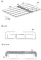
도 6의 (A)는 제 1 실시형태에 따른 입자선 치료 장치의 이동판의 일례를 나타내는 사시도, (B)는 (A)에 나타나 있는 이동판에 X선을 조사시켰을 때의 설명도.
도 7은 제 2 실시형태에 따른 입자선 치료 장치의 개략 구성도.
도 8은 부분 회전 갠트리의 치료 공간의 개략 구성도.
도 9의 (A)는 제 3 실시형태에 따른 입자선 치료 장치로서 회전 갠트리의 중심축에 따른 단면도, (B)는 제 3 실시형태에 따른 입자선 치료 장치로서 회전 갠트리의 중심축에 수직한 방향으로 절단한 입자선 치료 장치의 단면도.
도 10은 제 3 실시형태에 따른 입자선 치료 장치가 구비하는 이동 시트의 개략 단면도.
도 11의 (A)는 제 4 실시형태에 따른 입자선 치료 장치가 구비하는 이동판의 사시도, (B)는 (A)에 나타나 있는 I-I 단면의 단면도, (C)는 (A)에 나타나 있는 II-II 단면의 단면도.
도 12는 제 3 실시형태에 따른 입자선 치료 장치의 동작 수순을 나타내는 플로우차트.1 is a schematic configuration diagram of a particle beam treatment apparatus according to an embodiment.
Fig. 2 is a diagram showing an example in which a full circumference rotating gantry is used as an example of the particle beam treatment apparatus according to the first embodiment.
3A is a cross-sectional view along the central axis of the rotating gantry as the particle beam treatment apparatus according to the first embodiment, and (B) is perpendicular to the central axis of the rotating gantry as the particle beam treatment apparatus according to the first embodiment. Cross section of particle beam therapy device in the direction.
4 is a perspective view illustrating an example of a moving floor provided in a support guide;
Fig. 5 is a top view showing a lateral slide type as a modification of the moving floor.
FIG. 6: (A) is a perspective view which shows an example of the moving plate of the particle beam therapy apparatus which concerns on 1st Embodiment, (B) is explanatory drawing when X-ray is irradiated to the moving plate shown to (A). FIG.
7 is a schematic configuration diagram of a particle beam treatment apparatus according to a second embodiment.
8 is a schematic configuration diagram of a treatment space of a partially rotating gantry.
9A is a cross-sectional view along the central axis of the rotating gantry as the particle beam treatment apparatus according to the third embodiment, and (B) is perpendicular to the central axis of the rotating gantry as the particle beam treatment apparatus according to the third embodiment. Sectional view of the particle beam therapy device cut in the direction.
10 is a schematic cross-sectional view of a moving sheet included in the particle beam treatment apparatus according to the third embodiment.
(A) is a perspective view of the moving plate with which the particle beam therapy apparatus which concerns on 4th Embodiment is equipped, (B) is sectional drawing of the II cross section shown in (A), (C) is shown in (A). Section of II-II cross section.
12 is a flowchart showing an operation procedure of a particle beam treatment apparatus according to a third embodiment.
이하, 본 발명의 실시형태를 첨부 도면에 의거하여 설명한다.EMBODIMENT OF THE INVENTION Hereinafter, embodiment of this invention is described based on an accompanying drawing.
도 1은, 실시형태에 따른 입자선 치료 장치(10)(이하, 간단히「치료 장치(10)」라고 함)의 개략 구성도이다. 1 is a schematic configuration diagram of a particle beam treatment apparatus 10 (hereinafter, simply referred to as "
이온원(11)으로부터 방출된 양자 또는 탄소 이온 등의 하전입자는, 입자선 가속기(12)로 가속된 입자선 빔(B)(입자선(B))이 된다.Charged particles such as protons or carbon ions emitted from the ion source 11 become a particle beam beam B (particle beam B) accelerated by the
입자선(B)은, 자장을 이용해서 피조사체인 환자(13)가 있는 치료 건물(14)까지 유도된다. The particle beam B is guided to the
또한, 입자선(B)은, 가속기(12)와 회전 접합부(20)를 통해 접속된 입자선 빔 조사기(16)(이하, 간단히「입자선 조사기(16)」라고 함)로 유도된다. Moreover, the particle beam B is guide | induced to the particle beam beam irradiator 16 (henceforth simply "
그리고, 입자선(B)은, 입자선 빔 조사기(16)의 선단부로부터, 천판(18)에 고정된 환자(13)의 환부(19)를 향해서 출사(出射)된다.And the particle beam B is radiate | emitted from the front-end | tip part of the particle
조사 각도를 다양하게 변경하는 입자선 조사기(16)의 자세를 유지하기 위해서, 입자선 조사기(16)는, 회전 갠트리(21)에 지지된다. In order to maintain the posture of the
회전 갠트리(21)는, 입자선 조사기(16)의 지지체로서 마련되는 회전 구조체이다. The
회전 갠트리(21)가 치료 건물(14)에 대하여 회전 등의 변위를 함으로써 입자선 조사기(16)는 다양한 자세로 변위할 수 있다.
또한, 치료 건물(14)에 구축된 기초(22)에 고정된 치료대에 배치되는 천판(18)도, 환자(13)에 과잉의 부하가 걸리지 않는 범위에서 자세를 변하게 할 수 있다. In addition, the
환자(13) 또는 기사(38)(도 3의 (B)) 등이 천판(18)의 주위에 액세스하기 위해서, 천판(18)의 하방에는, 회전 갠트리(21)의 변위와는 무관하게 수평을 유지하는 바닥면이 배치된다. In order to allow the
이 바닥면 중 입자선 조사기(16)의 통과 궤도 상에 배치된 부분이 변위하지 않는 것이면, 입자선 조사기(16)의 변위를 저해한다.If the part of this bottom surface arrange | positioned on the passage trajectory of the
그래서, 적어도 이 통과 궤도 상의 바닥면은, 입자선 조사기(16)의 통과에 맞춰서 입자선 조사기(16)에 의한 점유 범위(23)(도 5)로부터 퇴피하는 이동바닥(24)으로 할 필요가 있다. Therefore, at least the bottom surface on this passage trajectory needs to be the moving
이동바닥(24)은, 기초(22)에 직접 또는 바닥면을 통해 고정되거나, 혹은 회전 갠트리(21) 내에 배치되는 지지 가이드(26a)에 슬라이딩 가능하게 계합(係合)됨으로써 슬라이딩한다. The moving
이동바닥(24)의 상세에 대해서는, 나중에 상술한다.The detail of the moving
또한, 치료 장치(10)에는 환자(13)를 향해서 설치되어 X선을 방출하는 X선 발생기(27a)(27)와, 환자(13)를 투과한 X선을 검출하는 X선 검출기(27b)(27)(Flat Panel Detector: FPD)가 구비되어 있다. Furthermore, the
이하, 이들 X선 발생기(27a) 및 FPD(27b)를 적절하게 합쳐서, X선 촬영 기기(27)라고 한다. Hereinafter, these
X선으로 환부(19)의 주변을 선명하게 촬영하기 위해서, X선 촬영 기기(27)는, 적어도 X선 촬영 시에는 입자선 조사기(16)의 통과 궤도 상 또는 그 부근에 배치될 필요가 있다.In order to clearly photograph the periphery of the affected
그래서, 실시형태에 따른 치료 장치(10)에서는, X선 촬영 기기(27)가, 비충돌 에어리어(31)에 고정되고, X선 발생기(27a)와 FPD(27b)가, 이동바닥(24)을 사이에 두고서 대향하는 위치에 설치된다. Thus, in the
비충돌 에어리어(31)란, 전자적인 위치 제어 기구를 사용하지 않아도 X선 촬영 기기(27)가 입자선 조사기(16), 회전 갠트리(21) 및 이동바닥(24)의 어느 것에도 충돌하지 않는 에어리어이다. The
이하, 비충돌 에어리어(31)의 설명도 포함해서, 도 2 내지 도 12에 나타나 있는 치료 장치(10)의 구체예를 설명한다.Hereinafter, the specific example of the
〔제 1 실시형태〕[First Embodiment]
도 2는, 제 1 실시형태에 따른 치료 장치(10)의 일례로서 전체 둘레 회전 갠트리(21a)를 채용한 예를 나타내는 도면이다. FIG. 2: is a figure which shows the example which employ | adopted the whole
입자선 조사기(16)에는, 도시를 생략하고 있지만, 진공 덕트, 빔 편향 전자석, 조사 필드 형성 전자석, 각종 모니터, 가대(架台), 그 밖의 구조물이 다수 설치되어 있고, 중량이 매우 크다. Although not shown, the
따라서, 이 중량이 큰 입자선 조사기(16)를 안정하게 지지해서 변위시키기 위해, 많은 경우, 도 2에 나타나 있는 바와 같은 원통 형상의 전체 둘레 회전 갠트리(21a)(21)가 사용된다.Therefore, in order to stably support and displace this large
이러한 전체 둘레 회전 갠트리(21a)는, 예를 들면 기초(22)에 설치된 회전 구동부(34)에 재치되어서, 이 회전 구동부(34)의 회전에 의해 원통의 중심축(Z축)의 주위를 회전한다.Such an entire
입자선 조사기(16)는, 치료 공간(36)으로 입자선 조사기(16)의 선단부를 돌출하게 해서 고정된다. The
전체 둘레 회전 갠트리(21a)의 동체부의 주변에서 기초(22)를 오목형으로 함으로써, 전체 둘레 회전 갠트리(21a)는, 입자선 조사기(16)의 외부 돌출부가 기초(22)에 충돌하지 않고 중심축의 주위를 360도 회전할 수 있다.By concave the
그리고, 도 3의 (A)는, 도 2에서 나타낸 전체 둘레 회전 갠트리(21a)의 치료 장치(10)로서 전체 둘레 회전 갠트리(21a)의 중심축에 따른 단면도이다. 3A is a cross-sectional view along the central axis of the full
또한 도 3의 (B)는, 이 중심축에 수직한 방향의 치료 장치(10)의 단면도이다. 3B is a cross-sectional view of the
또한 도 4는, 지지 가이드(26a)에 마련된 이동바닥(24)의 일례를 나타내는 사시도이다.4 is a perspective view which shows an example of the moving
(이동바닥(24)의 배치)(Placement of moving floor 24)
도 3의 (A) 및 도 4에 나타나 있는 바와 같이, 이동바닥(24)은, 예를 들면 길이 형상의 이동판(37)의 군(群)이 지지 가이드(26a)를 따라서 나란히 놓여 형성된다. As shown in FIG. 3 (A) and FIG. 4, the
지지 가이드(26a)는, 예를 들면 천판(18)의 하방에서 수평해지는 수평부, 및 전체 둘레 회전 갠트리(21a)의 내주면을 따라 만곡해서 이 수평부의 양단에 접속되는 만곡부로 구성된다.The
이러한 형상의 2개의 지지 가이드(26a)가, 서로 대향하는 쌍으로 되어서 이동판(37)의 길이 방향의 양단부에 계합된다. The two support guides 26a of such a shape are mutually opposing pairs, and engage with the both ends of the moving
이동판(37)은, 모터에 의해서 회전하는 롤러(도시하지 않음) 등을 통해 지지 가이드(26a)에 계합되는 것에 의해, 지지 가이드(26a)를 따라 슬라이딩 가능하게 된다. The moving
그리고, 천판(18)의 하방에 있어서의 이동판(37)의 군은, 수평한 포락면을 형성해서 이동바닥(24)이 된다. And the group of the moving
또, 본 명세서에 있어서「슬라이딩」이란, 접촉하는 부재가 접합(摺合)하도록 해서 상대적으로 이동하는 것을 의미한다. In addition, in this specification, "sliding" means that the member to contact contacts is relatively moved.
예를 들면, 롤러 또는 기어 등에 의해 상대적으로 이동할 경우나, 접촉한 매끄러운 면 상을 미끄러지게 하는 것 등이 슬라이딩에 포함된다.For example, sliding includes the case of moving relatively by a roller, a gear, etc., or sliding on the smooth surface which contacted.
입자선 조사기(16)는, 지지 가이드(26a)의 쌍에 끼워지는 위치에 선단부가 삽입되어서 고정된다. The
즉, 지지 가이드(26a)의 전체 둘레 중 일부는 이동판(37)이 존재하지 않는 영역이 있으며, 이 영역에 선단부가 삽입되어 있다.That is, a part of the entire circumference of the
전체 둘레 회전 갠트리(21a)의 회전에 의해 입자선 조사기(16)가 회전하면, 이동판(37)이 입자선 조사기(16)에 밀려서 입자선 조사기(16)의 주회 방향을 따라 슬라이딩한다. When the
즉, 이동판(37)을 입자선 조사기(16)의 진행 방향으로 슬라이딩시켜서, 입자선 조사기(16)에 의한 점유 범위(23)(도 5)로부터 퇴피시킨다. That is, the moving
또, 도 5의 이동바닥(24)의 변형예로서 횡 슬라이드식의 것을 나타내는 상면도에서 나타나 있는 바와 같이, 이동판(37)의 퇴피 방향은, 입자선 조사기(16)의 주회 방향에 대하여 수직해도 된다. Moreover, as shown in the top view which shows a lateral slide type as a modification of the moving
횡 슬라이드식의 이동바닥(24)의 경우, 예를 들면 복수의 직선 형상의 지지 가이드(26b)가 전체 둘레 회전 갠트리(21a)의 중심축을 따라 마련된다. In the case of the horizontal slide
그리고, 통과 센서(39)에 의해서 입자선 조사기(16)의 회전 갠트리의 중심축을 축으로 하는 둘레 각도(周角度, circumferential angle)를 검출한 슬라이딩 구동부(35)가 이동판(37)에 접속된 샤프트(41)를 지지 가이드(26b)를 따라서 슬라이딩시킨다.And the sliding drive part 35 which detected the circumferential angle which makes the central axis of the rotation gantry of the
여기서,「둘레 각도」란, 입자선 조사기(16)가 연직 상방에서 정지한 위치를 0도로 규정하고, 이 각도로부터 회전 갠트리(21)의 중심축을 중심으로 회전한 각도를 의미한다. 이하에 있어서도 마찬가지이다. Here, "circle angle" defines the position which the
이동바닥(24)은, 샤프트(41)에 의해 끌어당겨져 입자선 조사기(16)에 의한 점유 범위(23)로부터 퇴피한다.The moving bottom 24 is attracted by the shaft 41 and retracts from the
(X선 촬영 기기(27)의 배치)(Placement of X-ray photographing apparatus 27)
한편, 회전 갠트리(21)가 전체 둘레 회전 갠트리(21a)일 경우, X선 발생기(27a)는, 예를 들면 전체 둘레 회전 갠트리(21a)의 동체부에 고정된다. On the other hand, when the rotating
X선 발생기(27a)를 전체 둘레 회전 갠트리(21a)에 고정함으로써 전체 둘레 회전 갠트리(21a)와 함께 X선 발생기(27a)도 회전하므로, X선 발생기(27a)가 입자선 조사기(16)에 충돌할 일은 없다. By fixing the
즉, 전체 둘레 회전 갠트리(21a)의 동체부의 벽면 내부 및 이 동체부의 내주면과 이동바닥(24)의 만곡면으로 형성되는 간극(間隙)은, 비충돌 에어리어(31)이다. That is, the clearance gap formed in the inside of the wall surface of the trunk | drum of the whole
즉, 이 에어리어는, 전자적인 위치 제어 기구를 사용하지 않아도 X선 발생기(27a)가 입자선 조사기(16) 등에 충돌하지 않는 비충돌 에어리어(31)이다.That is, this area is the
또한 이 경우, 입자선 조사기(16)의 선단부에 FPD(27b)를 마련하면, FPD(27b)와 X선 발생기(27a)의 상대 각도는 변동하지 않아, X선 검출면의 설치 각도를 고정할 수 있다. In this case, when the
입자선 조사기(16) 자체에 설치된 FPD(27b)는, 입자선 조사기(16)에 충돌하여, 입자선 조사기(16)의 변위를 저해할 일이 없다. The
즉, FPD(27b)가 입자선 조사기(16)에 고정되어 있을 경우에는, 입자선 조사기(16)의 선단부 부근은, FPD(27b)가 입자선 조사기(16)의 변위를 저해하지 않는 범위 내에서, 비충돌 에어리어(31)이다.That is, when the
또한, 전체 둘레 회전 갠트리(21a)의 내부로 돌출한 입자선 조사기(16)의 돌출부에는, 이 돌출부를 피복하는 커버(17)가 마련된다. Moreover, the
FPD(27b)를 커버(17)의 내표면 또는 외표면에 마련했을 경우에도, FPD(27b)는 입자선 조사기(16) 등의 변위를 저해하지 않는다. Even when the
따라서, 커버(17)의 내표면 및 외표면에 FPD(27b)를 마련했을 경우에도, FPD(27b)는 비충돌 에어리어(31)에 마련된 것으로 된다.Therefore, even when the
또, FPD(27b)는, 설치 각도를 고정할 수 있는 경우에도, 입자선 조사기(16) 또는 커버(17)에 수납되는 것이어도 된다. Moreover, even if the installation angle can be fixed, the
또한, 전체 둘레 회전 갠트리(21a)의 내주면으로서 입자선 조사기(16)의 고정 부분이, 치료 공간(36)으로 돌출되어 노출하고 있을 경우도 있다. In addition, the fixed part of the
이 경우, 이 노출부(도시하지 않음)에 FPD(27b)를 설치해도 되고, 이 노출부 부근도 비충돌 에어리어(31)이다.In this case, the
또, X선 촬영 기기(27)는, 빔 조사 축으로부터 ±45도의 각도로 2쌍 설치되는 것이 바람직하다. In addition, the X-ray imaging apparatus 27 is preferably provided in two pairs at an angle of ± 45 degrees from the beam irradiation axis.
2방향으로부터의 X선 화상을 취득함으로써, 환부(19)의 3차원의 위치를 파악할 수 있다.By acquiring the X-ray image from two directions, the three-dimensional position of the
또한, 수평 방향 및 연직 방향에 각각 설치함으로써, 종래의 고정식의 조사 실과 공통인 화상 처리 방식을 사용할 수 있다. Moreover, by providing in the horizontal direction and the vertical direction, respectively, the image processing system common to the conventional fixed irradiation chamber can be used.
또한, X선 발생기(27a)와 FPD(27b)의 위치를 역전(逆轉)하여, X선 발생기(27a)를 입자선 조사기(16)의 선단부 부근 등 치료 공간(36)의 내부에, FPD(27b)를 전체 둘레 회전 갠트리(21a)에 설치해도 된다. In addition, the positions of the
이하, 특별히 명시하지 않지만, 모든 예에 있어서 X선 발생기(27a)와 FPD(27b)의 위치는 교환 가능하다.Hereinafter, although not specifically stated, the positions of the
(이동판(37)의 구성)(Configuration of the Moving Plate 37)
이와 같이 전체 둘레 회전 갠트리(21a)에 X선 발생기(27a)가 설치되어서 입자선 조사기(16) 등에 FPD(27b)가 설치되면, 이들 사이에는, 이동바닥(24)이 배치되게 된다. Thus, when the
즉, 이동바닥(24)에 의해 X선 발생기(27a)로부터 출사된 X선은, 이동바닥(24)에서 차폐되어서, 이동바닥(24)에 대해 X선 발생기(27a)와 반대의 측의 FPD(27b)까지 도달하지 않게 된다. That is, the X-ray radiated from the
그래서, 도 6의 (A)의 이동판(37)의 일례에서 나타나 있는 바와 같이, 이동판(37)을 X선의 투과율이 서로 다른 제 1 바닥부재(37a)와 제 2 바닥부재(37b)(37)로 구성한다. Thus, as shown in the example of the moving
이동판(37)의 모재가 되는 제 2 바닥부재(37b)는, 예를 들면 폭 400mm, 길이 2000mm 정도의 알루미늄 합금(예를 들면, JISA5052) 등이며, 환자(13)가 타고 내리는 바닥면으로서 충분한 강도를 갖는다. The
한편, 제 1 바닥부재(37a)(37)는, 제 2 바닥부재(37b)보다 X선 투과율이 높은 재료로 구성된다. On the other hand, the
즉, 제 2 바닥부재(37b)에 대한 제 1 바닥부재(37a)의 투과율의 비율(η)이 1보다 큰 것이 선택된다.That is, the ratio (eta) of the transmittance | permeability of the
예를 들면, 탄소섬유강화플라스틱(carbon-fiber-reinforced plastic, CFRP)은, X선 투과율에 대하여 강도가 높고, 제 1 바닥부재(37a)의 재료로서 적합하다.For example, carbon-fiber-reinforced plastic (CFRP) has high strength with respect to X-ray transmittance and is suitable as a material of the
CFRP의 X선 투과율은 동일한 두께의 알루미늄과 비교하여, 5배 정도인 것이 알려져 있다.It is known that the X-ray transmittance of CFRP is about five times compared to aluminum of the same thickness.
또, 제 1 바닥부재(37a)의 재질은, 제 2 바닥부재(37b)와 동일한 것일 경우도 있다. In addition, the material of the
제 1 바닥부재(37a)와 제 2 바닥부재(37b)가 동일한 재질이라 하더라도, 제 1 바닥부재(37a)의 두께를 얇게 함으로써, X선의 투과율을 높일 수 있다.Even if the
(제 1 바닥부재(37a)의 설치 위치)(Installation position of the
도 6의 (B)는, 도 6의 (A)에 나타나 있는 이동판(37)에 X선을 조사시켰을 때의 설명도이다. FIG. 6B is an explanatory diagram when X-rays are irradiated to the moving
X선 발생기(27a)로부터 출사되는 X선의 조사 범위는, 일정한 퍼짐(spread)을 갖는다. The irradiation range of X-rays emitted from the
환자(13)에는, 환부(19) 또는 환부(19)의 주변에 메워넣어진 마커 등 위치를 특정할 수 있는 최저한의 X선이 조사되면 된다. What is necessary is just to irradiate the patient 13 with the minimum X-ray which can specify the position etc. of the
즉, X선 발생기(27a)로부터 출사되는 X선 중 일부가 환자(13)에 도달하고, 그 후 FPD(27b)에서 검출된다.That is, some of the X-rays emitted from the
그래서, 제 1 바닥부재(37a)는, 도 6의 (B)에 나타나 있는 바와 같이, 이동판(37) 중 이 조사 범위와의 교차면(30)(도 6의 (B))을 포함하는 범위에 마련된다.Thus, as shown in FIG. 6B, the
제 1 바닥부재(37a)는, 예를 들면 도 6의 (B)에 나타나 있는 바와 같이, 프레임(43)이 마련되며, 이 프레임(43)을 통해 제 2 바닥부재(37b)에 결합된다. For example, as shown in FIG. 6B, the
또, 프레임(43)은, X선을 투과시키도록 하는 재료 선택 등을 하고 있을 경우를 제외하고, 제 2 바닥부재(37b)에 포함되는 것으로 한다.In addition, the
또한, 여기서 말하는「결합된다」에는, 제 2 바닥부재(37b)가 천공되어서, 이 천공부에 제 1 바닥부재(37a)가 끼워넣어질 경우도 당연히 포함하는 것으로 한다. In addition, the "coupled" here also includes the case where the
제 1 바닥부재(37a)의 결합에 나사 등을 사용하면, 제 1 바닥부재(37a)의 분리가 용이해지며, 이동판(37) 전체를 분리하지 않아도 X선 발생기(27a)를 확인할 수 있다. When a screw or the like is used for coupling the
나사에 의한 결합 이외에도, 접착제에 의한 접착 또는 용접 등을 이용해도 되며, 결합 방법은 한정되지 않는다.In addition to joining by screws, bonding or welding with an adhesive may be used, and the joining method is not limited.
또한, 천공부의 크기를 X선 발생기(27a)보다 한층 크게 함으로써, 이 천공부에서 X선 발생기(27a)를 용이하게 출납할 수 있다. In addition, by making the size of the perforation portion larger than the
또, 제 1 바닥부재(37a)를 마련한 이동판(37)은, 제 1 바닥부재(37a)를 마련하지 않은 이동판(37)과 비교해서, 강도가 낮아지는 경우가 많다. In addition, the moving
그래서, 최소한으로 되는 특정의 이동판(37)에만 제 1 바닥부재(37a)를 마련하는 것이 바람직하다.Therefore, it is preferable to provide the
예를 들면 2쌍의 X선 촬영 기기(27)는, 전술한 이유 때문에, 입자선 조사기(16)의 조사 축으로부터 ±45도의 각도로 고정되는 경우가 많다. For example, the two pairs of X-ray imaging apparatuses 27 are often fixed at an angle of ± 45 degrees from the irradiation axis of the
따라서, 이 경우에는, 제 1 바닥부재(37a)를 마련한 이동바닥(24)도, 조사 축으로부터 ±45도의 각도 및 그 주변의 수 개의 이동판(37)에 마련한다.Therefore, in this case, the
이상과 같이, 제 1 실시형태에 따른 치료 장치(10)에 의하면, 간소한 구성으로 양질의 X선 화상을 취득할 수 있다. As mentioned above, according to the
또한, X선 촬영 기기(27)를 수시 퇴피시킬 필요가 없기 때문에, 치료 시간을 단축할 수 있다.In addition, since the X-ray imaging apparatus 27 does not need to be evacuated at any time, the treatment time can be shortened.
〔제 2 실시형태〕 (부분 회전 갠트리(21b))[2nd Embodiment] (Partial
도 7은, 제 2 실시형태에 따른 치료 장치(10)의 개략 구성도이다. 7 is a schematic configuration diagram of a
최근, 도 7에 나타나 있는 바와 같이 레일 궤도(40), 혹은 원통의 일부 등을 사용한 부분 회전 갠트리(21b)(21)도 알려지고 있다. Recently, as shown in FIG. 7, the
또, 도 7에 있어서는, 입자선 조사기(16)에 접속되어서 입자선 조사기(16)와의 중량의 밸런스를 잡는 밸런스 웨이트 등의 각종 부수 기기는 생략되어 있다.In addition, in FIG. 7, various accessory apparatuses, such as the balance weight which are connected to the
도 7에 나타나 있는 바와 같은 부분 회전 갠트리(21b)에서는, 만곡 형상이며 360도보다 작은 각도 범위의 2개의 레일 궤도(40)가 마련된다. In the partially rotated
그리고, 이 2개의 레일 궤도(40)에 2개의 회전 보조체(25)가 계합된다. Then, two rotation aids 25 are engaged with these two rail tracks 40.
입자선 조사기(16)는, 이 회전 보조체(25)에 지지되어서, 천판(18)에 고정되는 환자(13)를 중심으로 360도보다 작은 각도로 회전한다.The
부분 회전 갠트리(21b)를 사용할 경우, 입자선 조사기(16)의 변위 각도를 제한하는 한편, 천판(18)을 수평으로 회전시킴으로써, 전체 둘레 회전 갠트리(21a) 와 마찬가지로 임의의 각도로부터의 입자선(B)의 조사가 가능해진다. In the case of using the
변위 각도를 제한함으로써, 천판(18)의 부근에 큰 비충돌 에어리어(31)를 확보할 수 있다. By limiting the displacement angle, a
제 2 실시형태에서는, 치료 장치(10)를 부분 회전 갠트리(21b)에 적용했을 경우에 대해 설명한다.In 2nd Embodiment, the case where the
도 8은, 부분 회전 갠트리(21b)의 치료 공간의 개략 구성도이다. 8 is a schematic configuration diagram of the treatment space of the
제 2 실시형태에 따른 치료 장치(10)는, 도 8에 나타나 있는 바와 같이, 제 1 실시형태와 달리, 회전 갠트리(21)의 동체부의 위치로부터 중심축과 수직한 방향에서 입퇴실(入退室)하는 것이 가능하다. As shown in FIG. 8, the
따라서, 치료 중에도 천판(18)이 기초(22)에 가까운 위치에 배치된다.Therefore, even during treatment, the
그래서, 예를 들면 2개 중 하나의 X선 발생기(27a)가 기초(22) 등의 부분 회전 갠트리(21b)가 회전해도 변위하지 않는 개소에 고정된다. Thus, for example, one of the two
X선이 기초(22)에 고정된 X선 발생기(27a)로부터 출사될 경우, FPD(27b)에 출사된 X선은, 이동바닥(24)에 의해 차폐됨 없이 환자(13)에 조사된다. When the X-rays are emitted from the
따라서, 기초(22)에 고정된 X선 발생기(27a)를 포함하는 X선 촬영 기기(27)에 대해서는, 이동판(37)에 대하여 제 1 실시형태와 같은 고안은 불필요해진다.Therefore, for the X-ray imaging apparatus 27 including the
그러나, 전술한 바와 같이, 환부(19)의 3차원의 위치 좌표를 취득하기 위해서는, 2개의 X선 발생기(27a)는, 예를 들면 90도의 각도로 설치될 필요가 있다.However, as mentioned above, in order to acquire the three-dimensional position coordinates of the
따라서, 부분 회전 갠트리(21b)이어도, 2개 중 나머지 하나의 X선 발생기(27a)는, 제 1 실시형태와 마찬가지로 이동바닥(24)을 사이에 두고 FPD(27b)와 대향하는 위치에 마련되어지게 된다.Therefore, even if it is the
그래서, 제 1 실시형태와 마찬가지로 이동판(37)에 제 1 바닥부재(37a)를 마련하여, 이 나머지 1쌍의 X선 촬영 기기(27)에 있어서도, X선 촬영을 할 수 있게 한다. Therefore, similarly to the first embodiment, the
도시를 생략하고 있지만, 기초(22)에 마련된 X선 발생기(27a)와 쌍이 되는 FPD에 대해서는, 예를 들면 입자선 조사기(16)의 선단에 마련된다. Although not shown, the FPD paired with the
또한, 부분 회전 갠트리(21b)에 마련된 X선 발생기(27a)와 쌍이 되는 FPD는, 예를 들면 기초(22)에 마련된다. In addition, the FPD paired with the
이와 같이 제 2 실시형태에 의하면, 부분 회전 갠트리(21b)가 부분 회전 갠트리(21b)일 경우에도, 제 1 실시형태와 마찬가지의 효과를 가질 수 있다.Thus, according to 2nd Embodiment, also when the
또, 회전 갠트리(21)가 부분 회전 갠트리(21b)인 것 이외는, 제 2 실시형태는 제 1 실시형태와 동일한 구조가 되므로, 중복되는 설명을 생략한다. The second embodiment has the same structure as that of the first embodiment except that the rotating
도면에 있어서도, 공통의 구성 또는 기능을 갖는 부분은 동일한 부호로 나타내고, 중복되는 설명을 생략한다.Also in the drawings, parts having a common structure or function are denoted by the same reference numerals and redundant descriptions are omitted.
이와 같이, 제 2 실시형태에 따른 치료 장치(10)에 있어서도 제 1 실시형태와 마찬가지의 효과를 얻을 수 있다.Thus, also in the
〔제 3 실시형태〕 (제 1 바닥부재(37a) 및 입자선 조사기(16)의 상대 둘레 각도 보정)[Third Embodiment] (Relative Perimeter Angle Correction of
도 9의 (A) 및 도 9의 (B)는, 제 3 실시형태에 따른 치료 장치(10)를 나타내는 개략 단면도이다. 9A and 9B are schematic cross-sectional views showing the
도 9의 (A)는, 도 3의 (A)와 마찬가지로, 도 2에서 나타낸 전체 둘레 회전 갠트리(21a)의 치료 장치(10)로서 전체 둘레 회전 갠트리(21a)의 중심축에 따른 단면도이다. FIG. 9: A is sectional drawing along the central axis of the
또한 도 9의 (B)는, 도 3의 (B)와 마찬가지로, 이 중심축에 수직한 방향의 치료 장치(10)의 단면도이다.FIG. 9B is a cross-sectional view of the
제 3 실시형태에 따른 치료 장치(10)는, 도 9에 나타나 있는 바와 같이, 제 1 실시형태의 구성에 더하여, 제 1 바닥부재(37a)의 위치를 검출하는 센서부(44)와, 이 제 1 바닥부재(37a)의 위치에 의거하여 이동판(37)을 슬라이딩시켜서 제 1 바닥부재(37a)를 X선 촬영 기기(27)의 조사 영역 상에 배치하는 위치 조정부(46)를 더 구비한다.As shown in FIG. 9, the
X선 발생기(27a)가 전체 둘레 회전 갠트리(21a)에 설치되어 있을 때, X선 발생기(27a)는, 중심축의 주위를 대략 진원(眞円) 모양으로 회전한다. When the
한편, 이동바닥(24)은 지지 가이드(26a)를 따라 이동하기 때문에, 이동바닥(24)도 또한 만곡부 및 수평부를 형성한다.On the other hand, since the moving bottom 24 moves along the
이 수평부에서는, 회전의 중심각에 대한 이동바닥(24)의 길이가 만곡부보다 짧아진다. In this horizontal portion, the length of the moving bottom 24 with respect to the center angle of rotation becomes shorter than the curved portion.
따라서, 전체 둘레 회전 갠트리(21a)와 이동판(37)이 동일한 각속도로 회전하면, 입자선 조사기(16)의 둘레 각도와 이동판(37)의 둘레 각도가 어긋나게 된다.Therefore, when the whole
즉, 어떤 둘레 각도에서는 45도의 둘레 각도 차이에 있었던 제 1 바닥부재(37a)가, 다른 둘레 각도에서는 X선 발생기(27a)의 조사 영역 상에서 어긋나버릴 경우가 있다.In other words, the
이들 제 1 바닥부재(37a)와 X선 발생기(27a)의 위치 관계가 어긋나면, X선 화상의 시야가 좁아질 경우나, X선이 차폐되어서 X선 화상을 취득할 수 없게 될 경우가 있다. If the positional relationship between these
입자선 조사기(16)의 둘레 각도 차이가 증가하면, 이 어긋남은 현저해진다.When the circumferential angle difference of the
그래서, 보통, 수평부에 있어서의 이러한 어긋남의 발생을 고려하여, 제 1 바닥부재(37a)는, 2개 이상의 서로 이웃한 이동판(37)에 마련된다. Therefore, in consideration of the occurrence of such misalignment in the horizontal portion, the
그러나, 2개 이상의 서로 이웃한 이동판(37)에 제 1 바닥부재(37a)가 마련되어 있을 경우에도, 프레임(43)이 X선을 차폐해버려 마커나 특징이 있는 뼈부위를 적절하게 특정할 수 없을 경우가 있다.However, even when two or more neighboring moving
그래서, 이동바닥(24)의 적어도 일부는, 입자선 조사기(16)와 연결되지 않고, 입자선 조사기(16)와는 독립하여 지지 가이드(26a) 상을 슬라이딩하기 위한 유도(裕度)를 가지고서 계합된다. Therefore, at least a part of the moving
여기서, 도 10은, 제 3 실시형태에 따른 치료 장치(10)가 구비하는 이동 시트(47)의 개략 단면도이다.Here, FIG. 10 is a schematic sectional drawing of the moving
구체적으로는, 예를 들면 도 10에 나타나 있는 바와 같이, 이동판(37)은 몇 개마다 그룹으로 나누어진다. Specifically, for example, as shown in FIG. 10, the moving
그룹 내의 인접하는 이동판(37)끼리는, 간격을 유지하여 가동(可動)하게 연결되어서 한 개의 이동 시트(47)를 형성한다. Adjacent moving
그리고, 인접하는 다른 이동 시트(47)와 위치가 중복 가능하게 지지 가이드(26a)에 계합된다.And the position with other adjacent moving
예를 들면, 지지 가이드(26a)에 내주측의 레인(lane) 및 외주측의 레인의 2개의 레인(도시하지 않음)을 마련한다. For example, the
그리고, 인접하는 이동 시트(47)를 내주측의 레인과 외주측의 레인으로 번갈아 계합시킨다. Then, the adjacent moving
인접하는 이동 시트(47)끼리는, 간극의 발생을 방지하기 위해, 인접하는 단부를 중복시켜서 배면 롤러(48)로 슬라이딩 가능하게 접속된다. In order to prevent generation | occurrence | production of the clearance gap, adjacent moving sheet | seats 47 overlap with the edge part which adjoins, and are slidably connected with the
이와 같이, 이동 시트(47)끼리의 중심(centroid)간 거리가 변화되는 유도를 가지고서 계합됨으로써, 입자선 조사기(16)와 제 1 바닥부재(37a)의 둘레 각도를 일치시킬 수 있다.In this way, by engaging with the induction that the distance between the centroids of the moving
또, 입자선 조사기(16)의 동체부에는, 복수 중 일부의 이동 시트(47)가 고정하여 접속되어 있다. In addition, some of the moving
기초(22) 등 변위하지 않는 개소에 설치된 센서부(44)는, 이와 같이 서로 계합된 이동 시트(47)를 향해서 설치되어 제 1 바닥부재(37a)의 위치를 검출한다. X선 발생기(27a)가 전체 둘레 회전 갠트리(21a)에 고정되어 있는 경우에는, 센서부(44)는 입자선 조사기(16)의 선단 부근에 설치해도 된다. The
검출의 방법에는, 예를 들면 프레임(43)에 형광 스티커를 붙이고, 이 형광 스티커의 반사를 광학적으로 검출하는 방법이 있다.As a method of detection, for example, there is a method of attaching a fluorescent sticker to the
또한, 센서부(44)를 사용하지 않고, 입자선 조사기(16)가 정지하는 둘레 각도와 제 1 바닥부재(37a)의 둘레 각도의 관계를 미리 기억해 두고, 이 관계에 의거하여, 검출한 입자선 조사기(16)가 정지한 둘레 각도에 대응하는 각도 보정량을 구해도 된다.In addition, the relationship between the circumferential angle at which the
어떤 경우에도, 이 정보는 위치 조정부(46)에 보내져서, 위치 조정부(46)에서 제 1 바닥부재(37a)와 X선 발생기(27a)의 조사 영역이 일치하도록 보정된다.In any case, this information is sent to the
각도 보정량의 산출에서는, 이동바닥의 수평부에서 이동 시트(47) 사이의 간극이 가능한 한 작아지도록 산출하는 것이 바람직하다. In calculation of an angle correction amount, it is preferable to calculate so that the clearance gap between the moving
각도 보정량이 이동 시트(47)의 중복된 단부의 유도를 초과해서 클 경우에, 이동바닥(24)의 수평부에 간극이 생겨버리기 때문이다.This is because a gap is generated in the horizontal portion of the
또한, 수평부에 있어서의 이동 시트(47)의 단부에는, 간극이 생겨버렸을 경우의 작은 물건의 낙하나 끼워짐 방지를 위해 롤 스크린 등의 가드를 마련하는 것이 바람직하다. 또한, 되도록이면 수평부에 간극이 생기지 않도록 각 이동 시트(47)를 구동시키는 것이 바람직하다. In addition, it is preferable to provide guards, such as a roll screen, in the edge part of the moving
위치 조정부(46)는, 제 1 실시형태와 X선 발생기(27a)의 상대 둘레 각도에 의거하여 이동 시트(47)를 슬라이딩시켜서 제 1 바닥부재(37a)를 조사 영역 상에 배치한다.The
이상과 같이, 임의의 둘레 각도에 있어서 X선 발생기(27a)와 제 1 바닥부재(37a)를 일치시킬 수 있으므로, 임의의 둘레 각도로부터의 X선 촬영이 가능해진다.As described above, since the
다음으로, 제 3 실시형태에 따른 치료 장치(10) 방법의 동작 수순을, 도 12의 플로우차트를 사용하여 설명한다(적절히 도 9를 참조). Next, the operation procedure of the method of the
먼저, 입자선 조사기(16)의 둘레 각도를 45도로 함으로써, X선의 출사 방향을 수평 방향 및 연직 방향으로 한다(S11).First, by making the circumferential angle of the
다음으로, 센서부(44)에서 제 1 바닥부재(37a)의 위치를 검출하고, 제 1 바닥부재(37a)의 둘레 각도를 조절해서 X선 발생기(27a)의 둘레 각도와 맞추고(S12), X선 촬영을 한다(S13). Next, the
X선은, 제 1 바닥부재(37a)를 투과하고, 또한 환자(13)의 환부(19) 부근을 투과해서 입자선 조사기(16)에 고정된 FPD(27b)에서 검출된다. The X-rays are detected by the
치료 계획에서 설정한 환부(19)에 입자선(B)이 정확하게 조사될 수 있도록 취득된 X선 화상을 바탕으로 환자(13)의 위치를 조절한다(S14).The position of the
환자(13)의 위치 조절 후, X선으로 재차 촬영을 한다(S15). After adjusting the position of the
재차 촬영에서 취득된 X선 화상을 확인하고, 환자(13)의 위치가 적절해질 때까지 X선 촬영 및 환자(13)의 위치 조절을 반복한다(S16:NO:S14로). The X-ray image acquired by the imaging is checked again, and the X-ray imaging and the position adjustment of the patient 13 are repeated until the position of the
위치 결정의 전후에서는, 환자(13)의 자세나 상황을 확인하기 위해 기사(38)가 이동바닥(24)을 타고 환자(13)에게 액세스하는 경우도 있다. Before and after positioning, the
환자(13)의 위치가 적절하면 위치 결정을 완료한다(S16:YES). If the position of the
다음으로, 입자선 조사기(16)를 회전해서 출사 위치에 배치한다(S17). Next, the
센서부(44)에서 제 1 바닥부재(37a)의 위치를 검출하고, 제 1 바닥부재(37a)를 슬라이딩해서 둘레 각도를 X선 발생기(27a)의 둘레 각도에 일치시킨다(S18).The
또, 제 1 바닥부재(37a)를 X선 발생기(27a)의 둘레 각도에 완전하게 일치시킬 수 없을 경우 등은, X선의 조사 영역에 제 1 바닥부재(37a)가 포함되도록 하면 된다. When the
호흡 동기 조사하지 않을 경우, 그대로 입자선 조사기(16)가 입자선(B)을 조사한다(S19:NO:S20). If the respiratory motivation is not irradiated, the
치료 계획에 따라서, 소정의 선량을 조사하면, 조사를 종료한다(S21). According to the treatment plan, when the predetermined dose is irradiated, the irradiation is terminated (S21).
다른 둘레 각도에서도 조사를 할 경우, 입자선 조사기(16)를 회전시켜서 다음 둘레 각도로 배치한다(S22:YES:S17로). When irradiating at another circumferential angle, the
계획된 모든 둘레 각도에서 조사를 한 후(S22:NO), 입자선 치료를 종료한다.After irradiation at all planned circumferential angles (S22: NO), the particle beam treatment ends.
또한 입자선 치료 방법에는, 환자(13)의 호흡에 의한 환부(19)의 주기적인 변위에 타이밍을 맞춰서 입자선(B)을 조사하는 호흡 동기 조사법이 있다. In addition, the particle beam treatment method includes a respiratory synchronous irradiation method in which the particle beam B is irradiated with timing at a periodic displacement of the
호흡 동기 조사법을 실시할 경우, X선 촬영을 해서 환부(19)의 위치를 확인한다(S19:YES:S23).When the respiratory synchronous irradiation method is performed, the position of the
그리고, 환부(19)가 최적의 위치에 이르렀을 때에, 타이밍을 맞춰서 입자선(B)을 조사한다(S24). When the
조사를 종료할 때까지, X선 촬영 및 입자선(B)의 조사를 한다(S25:NO:S23에). X-ray imaging and particle beam B are irradiated until completion | finish of irradiation (to S25: NO: S23).
특정한 둘레 각도에서의 입자선(B)의 조사 종료 후에는, 통상의 조사 치료법과 마찬가지로, 전체 둘레 회전 갠트리(21a)를 회전시켜서 입자선 조사기(16)를 다른 둘레 각도로 이동한다(S25:YES:S22:YES:S17로).After the irradiation of the particle beam B at the specific circumferential angle, the
또, 제 1 바닥부재(37a)의 둘레 각도를 조정할 수 있으므로, 입자선 조사기(16)를 당초의 45도의 둘레 각도로 되돌리지 않고, 정지하고 있는 둘레 각도에서 몇 번이고 X선 촬영을 실시할 수 있다. In addition, since the circumferential angle of the
또한, 예를 들면 빔 조사 직전에 환자의 몸상태가 악화하여, 일단 퇴실하고, 재차 치료대로 되돌아온 경우에도, 상기한 바와 같이 정지하고 있는 입자선 조사기(16)의 둘레 각도에 맞춰서 제 1 바닥부재(37a)의 둘레 각도를 조정하면, 입자선 조사기(16)의 둘레 각도를 초기 각도(위치 결정 각도)로 되돌리지 않아, 양호한 X선 촬영이 가능하게 된다.Further, for example, even when the patient's physical condition deteriorates immediately before the beam irradiation, and once the patient is discharged and returned to the treatment table, the first bottom member is adapted to the circumferential angle of the
입자선 조사기(16)의 회전, X선 장치의 구동 시스템 없이, 단시간에 위치 결정 확인 및 치료 재개가 가능해진다. Without the rotation of the
또, 전체 둘레 회전 갠트리(21a)에 관하여 설명했지만, 제 3 실시형태에서는 부분 회전 갠트리(21b)에서도 마찬가지로 적용할 수 있다.In addition, although the
또, 이동바닥(24)을 이동 시트(47)로 나누어서 정지한 둘레 각도의 보정을 하는 것 이외는, 제 3 실시형태는 제 1 실시형태와 동일한 구조 및 동작 수순으로 되므로, 중복되는 설명을 생략한다. The third embodiment has the same structure and operation procedure as the first embodiment except that the moving bottom 24 is divided by the moving
도면에 있어서도, 공통의 구성 또는 기능을 갖는 부분은 동일한 부호로 나타내고, 중복되는 설명을 생략한다.Also in the drawings, parts having a common structure or function are denoted by the same reference numerals and redundant descriptions are omitted.
이와 같이, 제 3 실시형태에 따른 치료 장치(10)에 의하면, 제 1 실시형태의 효과에 더하여, 임의의 둘레 각도로부터도 X선 발생기(27a)와 제 1 바닥부재(37a)의 둘레 각도를 일치시킬 수 있으므로, 임의의 둘레 각도에 있어서의 X선 촬영이 가능해진다.Thus, according to the
또한 X선 촬영 때마다 입자선 조사기(16)를 치료 개시 시의 둘레 각도(위치 결정 각도)로 되돌릴 필요가 없으므로, 치료 시간도 단축할 수 있다. Moreover, since it is not necessary to return the
마찬가지로 치료 개시 시의 둘레 각도(위치 결정 각도)로 되돌릴 필요가 없으므로, 입자선 조사 중인 환자(13)의 호흡이나 약간의 체위의 변경에 의한 환부(19)의 어긋남에 동기 또는 추미(追尾)하는 호흡 동기 조사 또는 동체 추미 조사도 가능해진다. Similarly, since it is not necessary to return to the circumferential angle (positioning angle) at the start of treatment, the synchronous or follow-up of the deviation of the
또한, 임의의 둘레 각도로부터 X선 촬영을 할 수 있으므로, 환부(19)와의 관계에서 최적인 둘레 각도로부터 X선 조사를 할 수 있다.In addition, since X-ray imaging can be performed from any circumferential angle, X-ray irradiation can be performed from the circumferential angle that is optimal in relation to the
〔제 4 실시형태〕[Fourth Embodiment]
도 11의 (A)는, 제 4 실시형태에 따른 치료 장치(10)의 이동판(37)의 사시도이다. FIG. 11A is a perspective view of a moving
또한, 도 11의 (B)는, 도 11의 (A)에 나타나 있는 I-I 단면, 즉 제 2 바닥부재(37b)의 단면도이다. 11B is a sectional view taken along the line I-I shown in FIG. 11A, that is, the
또한, 도 11의 (C)는, 도 11의 (A)에 나타나 있는 II-II 단면, 즉 제 1 바닥부재(37a)의 단면도이다.11C is a cross-sectional view of the II-II cross section shown in FIG. 11A, that is, the
제 4 실시형태에 따른 치료 장치(10)는, 도 11의 (A)에 나타나 있는 바와 같이, 주회 방향으로 서로 이웃한 2개 이상의 이동판(37)에 마련되는 제 1 바닥부재(37a)가, 제 2 바닥부재(37b)를 사이에 두지 않고 연속하고 있다. In the
즉, 제 1 실시형태에서 나타낸 프레임(43)(도 6)을 포함하지 않고, 주회 방향으로 제 1 바닥부재(37a)가 연속해서 배치된다.That is, without including the frame 43 (FIG. 6) shown in 1st Embodiment, the
즉, 주회 방향을 따라 2개로 나누어진 제 2 바닥부재(37b)에, 제 1 바닥부재(37a)가 결합됨으로써 접속하고 있다. That is, the
제 1 바닥부재(37a)의 강성을 확보하기 위해서, 제 1 바닥부재(37a)와 제 2 바닥부재(37b)의 결합부위에 리브(도시하지 않음)를 마련하여 제 1 바닥부재(37a)와 제 2 바닥부재(37b)를 결합해도 된다.In order to secure the rigidity of the
(투과 경로 길이의 조건)(Condition of the penetration path length)
연속해서 배치되는 제 1 바닥부재(37a)는, 제 2 바닥부재(37b)의 형상에 맞춰서, 예를 들면 L자형 또는 コ자형의 형상을 가질 경우가 있다. The
그러나, 이러한 형상의 제 1 바닥부재(37a)를 X선이 투과하면, 제 1 바닥부재(37a)에의 입사 지점 및 입사 각도가 연속적으로 변할 때, 그 투과 경로 길이는, 불연속으로 급변한다.However, when X-rays pass through the
즉, 제 1 바닥부재(37a)가 직각 형상과 같은 예리한 형상을 하고 있을 경우, 제 1 바닥부재(37a)와 X선 발생기(27a)의 상대 각도의 연속적인 변화에 의해, 투과 경로 길이는 불연속으로 급변하게 된다.That is, when the
이러한 투과 경로 길이의 급변에 의해, FPD(27b)에는, 어떤 물체가 있는 것으로 인식되는 급한 피크가 발생할 우려가 있다. Due to such a sudden change in the transmission path length, there is a fear that a sudden peak in which the
그래서, 제 1 바닥부재(37a)와 X선 발생기(27a)의 위치 관계가 변화되었을 때에, 제 1 바닥부재(37a)에 진입하는 X선의 투과 경로 길이가 급변하지 않는 형상으로 된다. Therefore, when the positional relationship between the
예를 들면, 도 11의 (C)에 나타나 있는 바와 같이, 제 1 바닥부재(37a)의 각 꼭지각은 가능한 한 매끄럽고 완만하게 만곡시키는 것이 바람직하다.For example, as shown in Fig. 11C, it is preferable that each vertex angle of the
또한, 제 1 바닥부재(37a)의 형상을 가능한 한 평탄하게 해서, 두께의 변화가 없게 한다. In addition, the shape of the
예를 들면, 도 11의 (B) 및 도 11의 (C)를 비교해서 알 수 있는 바와 같이, 제 1 바닥부재(37a)의 굴곡되어 있는 단부는, 이 굴곡부의 길이를 가능한 한 짧게 하는 것이 바람직하다.For example, as can be seen by comparing Figs. 11B and 11C, the bent end of the
또한, 제 1 바닥부재(37a)와 X선 발생기(27a)가 취할 수 있는 임의의 상대 위치로부터의 X선의 입사에 대하여도, 허용 상한으로서 설정한 길이를 초과하지 않도록 하는 형상으로 하는 것이 바람직하다.Moreover, it is preferable to make it into the shape which does not exceed the length set as an allowable upper limit also about the incidence of X-rays from arbitrary relative positions which the
또, 제 1 바닥부재(37a)를 프레임(43)을 마련하지 않고 연속해서 배치하는 것 및 이동판(37)의 형상을 규정한 것 이외는, 제 4 실시형태는 제 1 실시형태와 동일한 구조 및 동작 수순으로 되므로, 중복되는 설명을 생략한다. The fourth embodiment has the same structure as the first embodiment except that the
도면에 있어서도, 공통의 구성 또는 기능을 갖는 부분은 동일한 부호로 나타내고, 중복되는 설명을 생략한다.Also in the drawings, parts having a common structure or function are denoted by the same reference numerals and redundant descriptions are omitted.
이와 같이, 제 4 실시형태에 따른 치료 장치(10)에 의하면, 제 3 실시형태의 효과에 더하여, 센서부(44) 및 위치 조정부(46) 등에 의한 X선 발생기(27a)와 이동바닥(24)의 상대 위치의 각도 보정을 하지 않아도, X선 촬영을 할 수 있다.Thus, according to the
이상 설명한 적어도 하나의 실시형태의 치료 장치(10) 또는 입자선 치료 방법에 의하면, 이동판(37)에 제 1 바닥부재(37a)를 설치함으로써, 간소한 구성으로 양질의 X선 화상을 취득할 수 있는 동시에 치료 시간을 단축화하는 것이 가능해진다.According to the
본 발명의 몇 가지 실시형태를 설명했지만, 이들 실시형태는, 예로서 제시한 것이며, 발명의 범위를 한정하는 것은 의도하고 있지 않다. While certain embodiments have been described, these embodiments have been presented by way of example only, and are not intended to limit the scope of the inventions.
이들 실시형태는, 그 밖의 다양한 형태로 실시되는 것이 가능하며, 발명의 요지를 일탈하지 않는 범위에서, 다양한 생략, 치환, 변경, 조합을 행할 수 있다.These embodiments can be implemented in various other forms, and various omissions, substitutions, changes, and combinations can be made without departing from the spirit of the invention.
이들 실시형태나 그 변형은, 발명의 범위나 요지에 포함되는 것과 마찬가지로, 특허청구범위에 기재된 발명과 그 균등의 범위에 포함되는 것이다.These embodiments and modifications thereof are included in the invention described in the claims and their equivalents, as included in the scope and spirit of the invention.
Claims (13)
상기 입자선 빔 조사기를 지지하는 가동(可動) 지지체와,
상기 입자선 빔 조사기의 변위 궤도 상에 마련되는 동시에 피조사체를 재치(載置)하는 천판의 하방(下方)에서 수평한 포락면(包絡面)을 형성하도록 복수로 구성되며, 적어도 그 하나가 제 1 바닥부재와 X선의 투과율이 상기 제 1 바닥부재보다 작은 제 2 바닥부재를 구비하는 이동판과,
상기 입자선 빔 조사기, 상기 지지체 및 상기 이동판의 어느 것에도 충돌하지 않는 비충돌 에어리어에 마련되는 X선 발생기와,
상기 X선 발생기와 대향하는 위치에 설치되어 상기 제 1 바닥부재를 투과하는 X선을 검출하는 X선 검출기를 구비하는 것을 특징으로 하는 입자선 치료 장치.A particle beam beam irradiator which emits a particle beam beam,
A movable support for supporting the particle beam beam irradiator,
It is provided on the displacement trajectory of the said particle beam beam irradiator, and is comprised in multiple numbers so that the horizontal envelope may be formed below the top plate which mounts a to-be-projected object, At least one A moving plate having a first bottom member and a second bottom member having a transmittance of X-rays smaller than the first bottom member;
An X-ray generator provided in a non-collision area that does not collide with any of the particle beam beam irradiator, the support, and the moving plate;
And an X-ray detector provided at a position facing the X-ray generator to detect X-rays passing through the first bottom member.
상기 X선 발생기는 상기 지지체에 지지되는 입자선 치료 장치.The method of claim 1,
And the X-ray generator is supported on the support.
상기 X선 검출기는 상기 지지체에 지지되는 입자선 치료 장치.The method of claim 1,
And the X-ray detector is supported on the support.
서로 이웃한 2개 이상의 상기 이동판에 상기 제 1 바닥부재가 마련되는 입자선 치료 장치.The method of claim 1,
Particle beam treatment apparatus provided with the first bottom member on two or more of the moving plate adjacent to each other.
서로 이웃한 2개 이상의 상기 이동판이 마련되는 상기 제 1 바닥부재가, 상기 제 2 바닥부재를 사이에 두지 않고 연속하고 있는 입자선 치료 장치.The method of claim 4, wherein
And said first bottom member provided with two or more said moving plates adjacent to each other continues without interposing said second bottom member.
상기 제 1 바닥부재의 위치를 검출하는 센서부와,
상기 위치에 의거하여 상기 이동판을 이동시켜서 상기 제 1 바닥부재를 상기 X선의 조사 영역 상에 배치하는 위치 조정부를 구비하는 입자선 치료 장치.The method of claim 1,
A sensor unit detecting a position of the first floor member;
And a positioning device for moving the movable plate based on the position to position the first bottom member on the X-ray irradiation area.
상기 이동판은, 복수의 그룹으로 나누어지며,
상기 그룹 내의 인접하는 상기 이동판끼리는 연결되어 한 개의 이동 시트를 형성하고,
상기 이동 시트와 인접하는 다른 이동 시트의 중심(centroid)간 거리가 변화되는 입자선 치료 장치.The method of claim 1,
The moving plate is divided into a plurality of groups,
Adjacent moving plates in the group are connected to form a moving sheet,
The particle beam therapy apparatus of claim 1, wherein the distance between the centroids of the moving sheet and another adjacent moving sheet is changed.
상기 제 1 바닥부재와 상기 X선 발생기의 위치 관계가 변화되었을 때에 상기 제 1 바닥부재에 진입하는 X선의 투과 경로 길이가 급변하지 않는 입자선 치료 장치.The method of claim 1,
And a transmission path length of the X-rays entering the first floor member does not change rapidly when the positional relationship between the first floor member and the X-ray generator is changed.
상기 제 1 바닥부재를 구성하는 재질은 CFRP인 입자선 치료 장치.The method of claim 1,
Particle beam treatment apparatus is a material constituting the first bottom member is CFRP.
상기 지지체는, 상기 피조사체를 중심으로 해서 회전하는 원통 형상의 회전 구조체인 입자선 치료 장치.The method of claim 1,
The said support body is a particle beam treatment apparatus which is a cylindrical rotating structure which rotates centering on the said to-be-tested object.
상기 지지체는, 상기 피조사체를 중심으로 해서 270도 이하의 각도로 회전하는 입자선 치료 장치.The method of claim 1,
The support body is a particle beam treatment apparatus that rotates at an angle of 270 degrees or less around the irradiated object.
상기 이동판은, 상기 입자선 빔 조사기의 주회(周回) 방향을 따라 이동하는 입자선 치료 장치.The method of claim 1,
The moving plate moves in a circumferential direction of the particle beam beam irradiator.
상기 이동판은, 상기 입자선 빔 조사기의 주회 방향에 수직한 방향으로 이동하는 입자선 치료 장치.The method of claim 1,
The moving plate, the particle beam treatment apparatus moves in a direction perpendicular to the circumferential direction of the particle beam beam irradiator.
Applications Claiming Priority (3)
| Application Number | Priority Date | Filing Date | Title |
|---|---|---|---|
| JPJP-P-2015-192811 | 2015-09-30 | ||
| JP2015192811A JP6334489B2 (en) | 2015-09-30 | 2015-09-30 | Particle beam therapy system |
| PCT/JP2016/078762 WO2017057538A1 (en) | 2015-09-30 | 2016-09-29 | Particle beam therapy device |
Publications (2)
| Publication Number | Publication Date |
|---|---|
| KR20180048874A KR20180048874A (en) | 2018-05-10 |
| KR102009699B1 true KR102009699B1 (en) | 2019-08-13 |
Family
ID=58427484
Family Applications (1)
| Application Number | Title | Priority Date | Filing Date |
|---|---|---|---|
| KR1020187008954A KR102009699B1 (en) | 2015-09-30 | 2016-09-29 | Particle beam therapy device |
Country Status (6)
| Country | Link |
|---|---|
| US (2) | US10363438B2 (en) |
| EP (1) | EP3357535B1 (en) |
| JP (1) | JP6334489B2 (en) |
| KR (1) | KR102009699B1 (en) |
| CN (3) | CN108290051B (en) |
| WO (1) | WO2017057538A1 (en) |
Families Citing this family (7)
| Publication number | Priority date | Publication date | Assignee | Title |
|---|---|---|---|---|
| JP6523076B2 (en) * | 2015-06-30 | 2019-05-29 | 株式会社日立製作所 | Particle therapy system |
| JP6334489B2 (en) * | 2015-09-30 | 2018-05-30 | 株式会社東芝 | Particle beam therapy system |
| JP6878330B2 (en) | 2018-02-09 | 2021-05-26 | 株式会社東芝 | Particle therapy device |
| JP2021041005A (en) * | 2019-09-12 | 2021-03-18 | 株式会社日立製作所 | Particle beam radiation system and particle beam radiation facility |
| CN110841206A (en) * | 2019-11-22 | 2020-02-28 | 合肥中科离子医学技术装备有限公司 | Matching structure of rotating rack and internal telescopic floor |
| CN112915402A (en) * | 2019-12-06 | 2021-06-08 | 医科达(北京)医疗器械有限公司 | Cover for a radiotherapy apparatus |
| US20230022716A1 (en) * | 2021-07-20 | 2023-01-26 | Mevion Medical Systems, Inc. | Gantry having a retractable cover |
Citations (4)
| Publication number | Priority date | Publication date | Assignee | Title |
|---|---|---|---|---|
| JP3519248B2 (en) | 1997-08-08 | 2004-04-12 | 住友重機械工業株式会社 | Rotation irradiation room for radiation therapy |
| JP3927348B2 (en) | 2000-03-15 | 2007-06-06 | 三菱電機株式会社 | Rotating irradiation device |
| WO2009153864A1 (en) | 2008-06-18 | 2009-12-23 | 三菱電機株式会社 | Rotary irradiation device |
| US20140121441A1 (en) | 2012-10-26 | 2014-05-01 | ProNova Solutions, LLC | Active Floor for Proton Therapy |
Family Cites Families (17)
| Publication number | Priority date | Publication date | Assignee | Title |
|---|---|---|---|---|
| JPS519248A (en) | 1974-07-12 | 1976-01-24 | Mitsubishi Heavy Ind Ltd | |
| WO2006076545A2 (en) * | 2005-01-14 | 2006-07-20 | Indiana University Research And Technology Corporation | Automatic retractable floor system for a rotating gantry |
| US7193227B2 (en) * | 2005-01-24 | 2007-03-20 | Hitachi, Ltd. | Ion beam therapy system and its couch positioning method |
| JP4219905B2 (en) * | 2005-02-25 | 2009-02-04 | 株式会社日立製作所 | Rotating gantry for radiation therapy equipment |
| DE102007011399A1 (en) * | 2007-03-08 | 2008-09-11 | Siemens Ag | Particle therapy facility |
| JP2008264311A (en) * | 2007-04-23 | 2008-11-06 | Hitachi Ltd | Medical particle beam radiation apparatus |
| DE102007029192B3 (en) * | 2007-06-25 | 2009-01-29 | Siemens Ag | Gantry with alternative space for a particle therapy facility |
| JP2009109447A (en) * | 2007-11-01 | 2009-05-21 | Rigaku Corp | X-ray inspection apparatus and x-ray inspection method |
| JP2009148325A (en) * | 2007-12-19 | 2009-07-09 | Hitachi Ltd | Medical particle beam irradiator |
| JP2010054309A (en) * | 2008-08-27 | 2010-03-11 | Mitsubishi Heavy Ind Ltd | Radiotherapy apparatus using transmission type dosimeter |
| WO2010070737A1 (en) * | 2008-12-16 | 2010-06-24 | 株式会社島津製作所 | Particle beam treatment apparatus |
| ES2628757T3 (en) | 2008-12-31 | 2017-08-03 | Ion Beam Applications S.A. | Rolling floor for exploration cylinder |
| JP5680510B2 (en) * | 2011-09-07 | 2015-03-04 | 住友重機械工業株式会社 | Charged particle beam irradiation equipment |
| JP6058377B2 (en) * | 2012-12-12 | 2017-01-11 | 株式会社東芝 | Particle beam therapy system |
| JP6523076B2 (en) | 2015-06-30 | 2019-05-29 | 株式会社日立製作所 | Particle therapy system |
| JP6334489B2 (en) * | 2015-09-30 | 2018-05-30 | 株式会社東芝 | Particle beam therapy system |
| JP6654102B2 (en) * | 2016-05-31 | 2020-02-26 | 株式会社日立製作所 | Particle beam therapy system |
-
2015
- 2015-09-30 JP JP2015192811A patent/JP6334489B2/en active Active
-
2016
- 2016-09-29 EP EP16851709.2A patent/EP3357535B1/en active Active
- 2016-09-29 WO PCT/JP2016/078762 patent/WO2017057538A1/en active Application Filing
- 2016-09-29 CN CN201680058442.9A patent/CN108290051B/en active Active
- 2016-09-29 CN CN202110017093.9A patent/CN112827075B/en active Active
- 2016-09-29 CN CN202110017643.7A patent/CN112827076B/en active Active
- 2016-09-29 KR KR1020187008954A patent/KR102009699B1/en active IP Right Grant
- 2016-09-29 US US15/763,634 patent/US10363438B2/en active Active
-
2019
- 2019-06-11 US US16/437,375 patent/US10799721B2/en active Active
Patent Citations (4)
| Publication number | Priority date | Publication date | Assignee | Title |
|---|---|---|---|---|
| JP3519248B2 (en) | 1997-08-08 | 2004-04-12 | 住友重機械工業株式会社 | Rotation irradiation room for radiation therapy |
| JP3927348B2 (en) | 2000-03-15 | 2007-06-06 | 三菱電機株式会社 | Rotating irradiation device |
| WO2009153864A1 (en) | 2008-06-18 | 2009-12-23 | 三菱電機株式会社 | Rotary irradiation device |
| US20140121441A1 (en) | 2012-10-26 | 2014-05-01 | ProNova Solutions, LLC | Active Floor for Proton Therapy |
Also Published As
| Publication number | Publication date |
|---|---|
| EP3357535A4 (en) | 2019-07-10 |
| EP3357535B1 (en) | 2023-08-02 |
| CN108290051A (en) | 2018-07-17 |
| WO2017057538A1 (en) | 2017-04-06 |
| EP3357535A1 (en) | 2018-08-08 |
| CN108290051B (en) | 2021-01-22 |
| JP2017064018A (en) | 2017-04-06 |
| US20180289981A1 (en) | 2018-10-11 |
| CN112827075B (en) | 2023-09-01 |
| KR20180048874A (en) | 2018-05-10 |
| CN112827075A (en) | 2021-05-25 |
| US10363438B2 (en) | 2019-07-30 |
| JP6334489B2 (en) | 2018-05-30 |
| US20190308034A1 (en) | 2019-10-10 |
| CN112827076A (en) | 2021-05-25 |
| CN112827076B (en) | 2023-05-30 |
| US10799721B2 (en) | 2020-10-13 |
Similar Documents
| Publication | Publication Date | Title |
|---|---|---|
| KR102009699B1 (en) | Particle beam therapy device | |
| US10695587B2 (en) | Particle beam therapy system having X-ray detectors attached to a particle beam irradiation system | |
| JP4228018B2 (en) | Medical equipment | |
| JP6654102B2 (en) | Particle beam therapy system | |
| US20130163723A1 (en) | Method for Correctively Adjusting a Beam for Irradiating a Moving Target Volume | |
| US7418080B2 (en) | Support and radiation therapy system | |
| JP6433792B2 (en) | Particle beam therapy apparatus and imaging method using the same | |
| JP5829162B2 (en) | X-ray equipment | |
| JP6606218B2 (en) | Particle beam therapy apparatus, operation method thereof, and moving plate | |
| JP2016106756A (en) | Radiotherapy system | |
| JP6104839B2 (en) | Radiation therapy equipment | |
| JP2007267971A (en) | Radiation irradiation apparatus | |
| JP6829297B2 (en) | Particle beam therapy device | |
| JP4436340B2 (en) | Multi-leaf collimator and radiotherapy device | |
| WO2019008793A1 (en) | Particle beam irradiation apparatus | |
| US10124191B2 (en) | Hadron therapy installation comprising an imaging device |
Legal Events
| Date | Code | Title | Description |
|---|---|---|---|
| A201 | Request for examination | ||
| E902 | Notification of reason for refusal | ||
| E701 | Decision to grant or registration of patent right | ||
| GRNT | Written decision to grant |