EP3357535B1 - Particle beam therapy device - Google Patents
Particle beam therapy device Download PDFInfo
- Publication number
- EP3357535B1 EP3357535B1 EP16851709.2A EP16851709A EP3357535B1 EP 3357535 B1 EP3357535 B1 EP 3357535B1 EP 16851709 A EP16851709 A EP 16851709A EP 3357535 B1 EP3357535 B1 EP 3357535B1
- Authority
- EP
- European Patent Office
- Prior art keywords
- particle beam
- floor member
- ray
- floor
- therapy apparatus
- Prior art date
- Legal status (The legal status is an assumption and is not a legal conclusion. Google has not performed a legal analysis and makes no representation as to the accuracy of the status listed.)
- Active
Links
- 239000002245 particle Substances 0.000 title claims description 146
- 238000002560 therapeutic procedure Methods 0.000 title claims description 42
- 230000005540 biological transmission Effects 0.000 claims description 16
- 238000006073 displacement reaction Methods 0.000 claims description 13
- 239000000463 material Substances 0.000 claims description 9
- 238000002834 transmittance Methods 0.000 claims description 8
- 239000004918 carbon fiber reinforced polymer Substances 0.000 claims description 5
- 230000008878 coupling Effects 0.000 claims description 3
- 238000010168 coupling process Methods 0.000 claims description 3
- 238000005859 coupling reaction Methods 0.000 claims description 3
- 238000003384 imaging method Methods 0.000 description 39
- 238000002438 flame photometric detection Methods 0.000 description 27
- 230000003902 lesion Effects 0.000 description 19
- 238000000034 method Methods 0.000 description 14
- 238000010586 diagram Methods 0.000 description 10
- 238000012545 processing Methods 0.000 description 8
- 230000029058 respiratory gaseous exchange Effects 0.000 description 8
- 238000012937 correction Methods 0.000 description 6
- 230000001360 synchronised effect Effects 0.000 description 6
- 230000036544 posture Effects 0.000 description 5
- 230000000694 effects Effects 0.000 description 4
- 229910052751 metal Inorganic materials 0.000 description 4
- 239000002184 metal Substances 0.000 description 4
- 206010028980 Neoplasm Diseases 0.000 description 3
- 201000011510 cancer Diseases 0.000 description 3
- 238000001514 detection method Methods 0.000 description 3
- 238000009434 installation Methods 0.000 description 3
- 230000007246 mechanism Effects 0.000 description 3
- 230000002093 peripheral effect Effects 0.000 description 3
- 229910000838 Al alloy Inorganic materials 0.000 description 2
- 229910052799 carbon Inorganic materials 0.000 description 2
- -1 carbon ions Chemical class 0.000 description 2
- 239000003550 marker Substances 0.000 description 2
- 238000012986 modification Methods 0.000 description 2
- 230000004048 modification Effects 0.000 description 2
- 238000002727 particle therapy Methods 0.000 description 2
- 230000005855 radiation Effects 0.000 description 2
- OKTJSMMVPCPJKN-UHFFFAOYSA-N Carbon Chemical compound [C] OKTJSMMVPCPJKN-UHFFFAOYSA-N 0.000 description 1
- 229910000831 Steel Inorganic materials 0.000 description 1
- 239000000853 adhesive Substances 0.000 description 1
- 229910052782 aluminium Inorganic materials 0.000 description 1
- XAGFODPZIPBFFR-UHFFFAOYSA-N aluminium Chemical compound [Al] XAGFODPZIPBFFR-UHFFFAOYSA-N 0.000 description 1
- 210000000988 bone and bone Anatomy 0.000 description 1
- 238000012790 confirmation Methods 0.000 description 1
- 239000011521 glass Substances 0.000 description 1
- 229910002804 graphite Inorganic materials 0.000 description 1
- 239000010439 graphite Substances 0.000 description 1
- 150000002500 ions Chemical class 0.000 description 1
- 230000001678 irradiating effect Effects 0.000 description 1
- 210000000056 organ Anatomy 0.000 description 1
- 230000000737 periodic effect Effects 0.000 description 1
- 239000004033 plastic Substances 0.000 description 1
- 229920003023 plastic Polymers 0.000 description 1
- 238000003672 processing method Methods 0.000 description 1
- 230000002035 prolonged effect Effects 0.000 description 1
- 238000005096 rolling process Methods 0.000 description 1
- 239000010959 steel Substances 0.000 description 1
- 238000003466 welding Methods 0.000 description 1
Images


Classifications
-
- A—HUMAN NECESSITIES
- A61—MEDICAL OR VETERINARY SCIENCE; HYGIENE
- A61B—DIAGNOSIS; SURGERY; IDENTIFICATION
- A61B6/00—Apparatus or devices for radiation diagnosis; Apparatus or devices for radiation diagnosis combined with radiation therapy equipment
- A61B6/10—Safety means specially adapted therefor
- A61B6/102—Protection against mechanical damage, e.g. anti-collision devices
-
- A—HUMAN NECESSITIES
- A61—MEDICAL OR VETERINARY SCIENCE; HYGIENE
- A61N—ELECTROTHERAPY; MAGNETOTHERAPY; RADIATION THERAPY; ULTRASOUND THERAPY
- A61N5/00—Radiation therapy
- A61N5/10—X-ray therapy; Gamma-ray therapy; Particle-irradiation therapy
- A61N5/1077—Beam delivery systems
- A61N5/1081—Rotating beam systems with a specific mechanical construction, e.g. gantries
-
- A—HUMAN NECESSITIES
- A61—MEDICAL OR VETERINARY SCIENCE; HYGIENE
- A61N—ELECTROTHERAPY; MAGNETOTHERAPY; RADIATION THERAPY; ULTRASOUND THERAPY
- A61N5/00—Radiation therapy
- A61N5/10—X-ray therapy; Gamma-ray therapy; Particle-irradiation therapy
- A61N5/1048—Monitoring, verifying, controlling systems and methods
- A61N5/1049—Monitoring, verifying, controlling systems and methods for verifying the position of the patient with respect to the radiation beam
-
- A—HUMAN NECESSITIES
- A61—MEDICAL OR VETERINARY SCIENCE; HYGIENE
- A61B—DIAGNOSIS; SURGERY; IDENTIFICATION
- A61B6/00—Apparatus or devices for radiation diagnosis; Apparatus or devices for radiation diagnosis combined with radiation therapy equipment
- A61B6/02—Arrangements for diagnosis sequentially in different planes; Stereoscopic radiation diagnosis
- A61B6/022—Stereoscopic imaging
-
- A—HUMAN NECESSITIES
- A61—MEDICAL OR VETERINARY SCIENCE; HYGIENE
- A61B—DIAGNOSIS; SURGERY; IDENTIFICATION
- A61B6/00—Apparatus or devices for radiation diagnosis; Apparatus or devices for radiation diagnosis combined with radiation therapy equipment
- A61B6/04—Positioning of patients; Tiltable beds or the like
- A61B6/0407—Supports, e.g. tables or beds, for the body or parts of the body
- A61B6/0442—Supports, e.g. tables or beds, for the body or parts of the body made of non-metallic materials
-
- A—HUMAN NECESSITIES
- A61—MEDICAL OR VETERINARY SCIENCE; HYGIENE
- A61B—DIAGNOSIS; SURGERY; IDENTIFICATION
- A61B6/00—Apparatus or devices for radiation diagnosis; Apparatus or devices for radiation diagnosis combined with radiation therapy equipment
- A61B6/04—Positioning of patients; Tiltable beds or the like
- A61B6/0487—Motor-assisted positioning
-
- A—HUMAN NECESSITIES
- A61—MEDICAL OR VETERINARY SCIENCE; HYGIENE
- A61B—DIAGNOSIS; SURGERY; IDENTIFICATION
- A61B6/00—Apparatus or devices for radiation diagnosis; Apparatus or devices for radiation diagnosis combined with radiation therapy equipment
- A61B6/10—Safety means specially adapted therefor
- A61B6/107—Protection against radiation, e.g. shielding
-
- A—HUMAN NECESSITIES
- A61—MEDICAL OR VETERINARY SCIENCE; HYGIENE
- A61B—DIAGNOSIS; SURGERY; IDENTIFICATION
- A61B6/00—Apparatus or devices for radiation diagnosis; Apparatus or devices for radiation diagnosis combined with radiation therapy equipment
- A61B6/12—Arrangements for detecting or locating foreign bodies
-
- A—HUMAN NECESSITIES
- A61—MEDICAL OR VETERINARY SCIENCE; HYGIENE
- A61B—DIAGNOSIS; SURGERY; IDENTIFICATION
- A61B6/00—Apparatus or devices for radiation diagnosis; Apparatus or devices for radiation diagnosis combined with radiation therapy equipment
- A61B6/40—Arrangements for generating radiation specially adapted for radiation diagnosis
- A61B6/4007—Arrangements for generating radiation specially adapted for radiation diagnosis characterised by using a plurality of source units
- A61B6/4014—Arrangements for generating radiation specially adapted for radiation diagnosis characterised by using a plurality of source units arranged in multiple source-detector units
-
- A—HUMAN NECESSITIES
- A61—MEDICAL OR VETERINARY SCIENCE; HYGIENE
- A61B—DIAGNOSIS; SURGERY; IDENTIFICATION
- A61B6/00—Apparatus or devices for radiation diagnosis; Apparatus or devices for radiation diagnosis combined with radiation therapy equipment
- A61B6/42—Arrangements for detecting radiation specially adapted for radiation diagnosis
- A61B6/4266—Arrangements for detecting radiation specially adapted for radiation diagnosis characterised by using a plurality of detector units
-
- A—HUMAN NECESSITIES
- A61—MEDICAL OR VETERINARY SCIENCE; HYGIENE
- A61B—DIAGNOSIS; SURGERY; IDENTIFICATION
- A61B6/00—Apparatus or devices for radiation diagnosis; Apparatus or devices for radiation diagnosis combined with radiation therapy equipment
- A61B6/44—Constructional features of apparatus for radiation diagnosis
- A61B6/4429—Constructional features of apparatus for radiation diagnosis related to the mounting of source units and detector units
- A61B6/4435—Constructional features of apparatus for radiation diagnosis related to the mounting of source units and detector units the source unit and the detector unit being coupled by a rigid structure
-
- A—HUMAN NECESSITIES
- A61—MEDICAL OR VETERINARY SCIENCE; HYGIENE
- A61B—DIAGNOSIS; SURGERY; IDENTIFICATION
- A61B6/00—Apparatus or devices for radiation diagnosis; Apparatus or devices for radiation diagnosis combined with radiation therapy equipment
- A61B6/44—Constructional features of apparatus for radiation diagnosis
- A61B6/4429—Constructional features of apparatus for radiation diagnosis related to the mounting of source units and detector units
- A61B6/4452—Constructional features of apparatus for radiation diagnosis related to the mounting of source units and detector units the source unit and the detector unit being able to move relative to each other
-
- A—HUMAN NECESSITIES
- A61—MEDICAL OR VETERINARY SCIENCE; HYGIENE
- A61B—DIAGNOSIS; SURGERY; IDENTIFICATION
- A61B6/00—Apparatus or devices for radiation diagnosis; Apparatus or devices for radiation diagnosis combined with radiation therapy equipment
- A61B6/50—Apparatus or devices for radiation diagnosis; Apparatus or devices for radiation diagnosis combined with radiation therapy equipment specially adapted for specific body parts; specially adapted for specific clinical applications
-
- A—HUMAN NECESSITIES
- A61—MEDICAL OR VETERINARY SCIENCE; HYGIENE
- A61B—DIAGNOSIS; SURGERY; IDENTIFICATION
- A61B6/00—Apparatus or devices for radiation diagnosis; Apparatus or devices for radiation diagnosis combined with radiation therapy equipment
- A61B6/58—Testing, adjusting or calibrating thereof
- A61B6/587—Alignment of source unit to detector unit
-
- A—HUMAN NECESSITIES
- A61—MEDICAL OR VETERINARY SCIENCE; HYGIENE
- A61N—ELECTROTHERAPY; MAGNETOTHERAPY; RADIATION THERAPY; ULTRASOUND THERAPY
- A61N5/00—Radiation therapy
- A61N5/10—X-ray therapy; Gamma-ray therapy; Particle-irradiation therapy
-
- A—HUMAN NECESSITIES
- A61—MEDICAL OR VETERINARY SCIENCE; HYGIENE
- A61N—ELECTROTHERAPY; MAGNETOTHERAPY; RADIATION THERAPY; ULTRASOUND THERAPY
- A61N5/00—Radiation therapy
- A61N5/10—X-ray therapy; Gamma-ray therapy; Particle-irradiation therapy
- A61N5/1048—Monitoring, verifying, controlling systems and methods
- A61N5/1064—Monitoring, verifying, controlling systems and methods for adjusting radiation treatment in response to monitoring
- A61N5/1065—Beam adjustment
-
- A—HUMAN NECESSITIES
- A61—MEDICAL OR VETERINARY SCIENCE; HYGIENE
- A61N—ELECTROTHERAPY; MAGNETOTHERAPY; RADIATION THERAPY; ULTRASOUND THERAPY
- A61N5/00—Radiation therapy
- A61N5/10—X-ray therapy; Gamma-ray therapy; Particle-irradiation therapy
- A61N5/1048—Monitoring, verifying, controlling systems and methods
- A61N5/1071—Monitoring, verifying, controlling systems and methods for verifying the dose delivered by the treatment plan
-
- A—HUMAN NECESSITIES
- A61—MEDICAL OR VETERINARY SCIENCE; HYGIENE
- A61N—ELECTROTHERAPY; MAGNETOTHERAPY; RADIATION THERAPY; ULTRASOUND THERAPY
- A61N5/00—Radiation therapy
- A61N5/10—X-ray therapy; Gamma-ray therapy; Particle-irradiation therapy
- A61N5/1077—Beam delivery systems
- A61N5/1078—Fixed beam systems
-
- A—HUMAN NECESSITIES
- A61—MEDICAL OR VETERINARY SCIENCE; HYGIENE
- A61B—DIAGNOSIS; SURGERY; IDENTIFICATION
- A61B6/00—Apparatus or devices for radiation diagnosis; Apparatus or devices for radiation diagnosis combined with radiation therapy equipment
- A61B6/42—Arrangements for detecting radiation specially adapted for radiation diagnosis
- A61B6/4208—Arrangements for detecting radiation specially adapted for radiation diagnosis characterised by using a particular type of detector
- A61B6/4233—Arrangements for detecting radiation specially adapted for radiation diagnosis characterised by using a particular type of detector using matrix detectors
-
- A—HUMAN NECESSITIES
- A61—MEDICAL OR VETERINARY SCIENCE; HYGIENE
- A61B—DIAGNOSIS; SURGERY; IDENTIFICATION
- A61B6/00—Apparatus or devices for radiation diagnosis; Apparatus or devices for radiation diagnosis combined with radiation therapy equipment
- A61B6/44—Constructional features of apparatus for radiation diagnosis
- A61B6/4476—Constructional features of apparatus for radiation diagnosis related to motor-assisted motion of the source unit
-
- A—HUMAN NECESSITIES
- A61—MEDICAL OR VETERINARY SCIENCE; HYGIENE
- A61N—ELECTROTHERAPY; MAGNETOTHERAPY; RADIATION THERAPY; ULTRASOUND THERAPY
- A61N5/00—Radiation therapy
- A61N5/10—X-ray therapy; Gamma-ray therapy; Particle-irradiation therapy
- A61N5/1048—Monitoring, verifying, controlling systems and methods
- A61N5/1049—Monitoring, verifying, controlling systems and methods for verifying the position of the patient with respect to the radiation beam
- A61N2005/1061—Monitoring, verifying, controlling systems and methods for verifying the position of the patient with respect to the radiation beam using an x-ray imaging system having a separate imaging source
-
- A—HUMAN NECESSITIES
- A61—MEDICAL OR VETERINARY SCIENCE; HYGIENE
- A61N—ELECTROTHERAPY; MAGNETOTHERAPY; RADIATION THERAPY; ULTRASOUND THERAPY
- A61N5/00—Radiation therapy
- A61N5/10—X-ray therapy; Gamma-ray therapy; Particle-irradiation therapy
- A61N2005/1085—X-ray therapy; Gamma-ray therapy; Particle-irradiation therapy characterised by the type of particles applied to the patient
- A61N2005/1087—Ions; Protons
Definitions
- Embodiments of the present invention relate to a particle beam therapy apparatus (i.e., particle beam therapy device) equipped with a rotating gantry.
- a particle beam therapy apparatus i.e., particle beam therapy device equipped with a rotating gantry.
- a particle beam therapy method is widely used.
- a cancer lesion area is irradiated with a particle beam that is generated by accelerating charged particles such as protons and carbon ions to high energy.
- a particle beam irradiator is fixed to a cylindrical rotating gantry to rotate together, thereby is changed its irradiation angle.
- the inner space of the rotating gantry serving as a treatment room is provided with a movable floor that maintains a flat horizontal floor surface regardless of the rotation of the rotating gantry.
- a technician accesses a patient before and after treatment and the patient comes down from the treatment table in case of emergency.
- the movable floor slides in accordance with the displacement of the tip portion.
- X-ray imaging is performed so that the position and shape of the lesion area are accurately analyzed.
- an X-ray generator for radiating X-rays toward the patient and an X-ray detector for detecting X-rays transmitted through the patient are arranged in the treatment space.
- the arms being controlled so as not to hinder the replacements of other devices, the X-ray generator is placed in the vicinity of the lesion area only at the time of X-ray irradiation, and after the completion of imaging, the X-ray generators are retracted.
- the above-described technique has a problem that the arms and their control mechanisms complicate the particle beam therapy apparatus and the treatment time is prolonged by the arrangement time and retraction time of the X-ray imaging devices.
- X-ray images acquired by X-ray imaging are required to be clear to the extent that the position of the lesion area can be accurately specified.
- An object of the present invention is to provide a particle beam therapy apparatus that can acquire a high-quality X-ray image with a simple structure and shorten treatment time.
- a particle beam therapy apparatus has the features of claim 1 and inter alia includes: a particle beam irradiator configured to output a particle beam; a supporting structure configured to be movable and support the particle beam irradiator; a plurality of movable plates disposed on a displacement trajectory of the particle beam irradiator, forming a substantially horizontal enveloping surface below a table for placing an irradiation object, and including a first floor member and a second floor member in at least one of the plurality of movable plates, the first floor member being made of a material that is higher in X-ray transmittance than the second floor member; an X-ray generator provided in a non-collision area where the X-ray generator does not collide with any of the particle beam irradiator, the supporting structure, and the plurality of movable plates; and an X-ray detector installed at a position where the X-ray detector faces the X-ray generator and detects X-rays transmitted through the first
- the second floor member is punched and the first floor member is removably fit into the punched portion, thereby coupling the first floor member to the second floor member, and the size of the punched portion is set such that the X-ray generator can be taken in and out through the punched portion when the first floor member is removed.
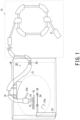
- Fig. 1 is a schematic configuration diagram of the particle beam therapy apparatus 10 (hereinafter simply referred to as the treatment apparatus 10) according to one embodiment.
- the particle beam B is guided with magnetic field to a treatment building 14 where a patient 13 as an irradiation object is present.
- the particle beam B is guided to a particle beam irradiator 16 that is connected to the accelerator 12 via a rotary joint 20, and then is outputted toward the lesion area 19 of the patient 13 fixed to the table 18 from the tip portion of the particle beam irradiator 16.
- the particle beam irradiator 16 In order to maintain the posture of the particle beam irradiator 16 that variously changes its irradiation angle, the particle beam irradiator 16 is supported by a rotating gantry 21.
- the rotating gantry 21 is a rotating structure provided as a supporting structure for supporting the particle beam irradiator 16.
- the particle beam irradiator 16 can take various postures subjecting the displacement, such as rotation, of the rotating gantry 21 with respect to the treatment building 14.
- the table 18 can also change the posture within such a range that excessive load is not exerted on the patient 13.
- a floor surface configured to keep horizontality regardless of displacement of the rotating gantry 21 is disposed below the table 18.
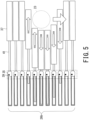
- At least the floor surface in the passing trajectory needs to be configured to be a movable floor 24 that is retracted from an occupied area 23 ( Fig. 5 ) to be occupied by the particle beam irradiator 16 in accordance with passage of the particle beam irradiator 16.
- the movable floor 24 slides by being fixed to the base 22 directly or via the floor surface or by being slidably engaged with support guides 26a disposed inside the rotating gantry 21.
- the treatment apparatus 10 is equipped with X-ray generators 27a (27) and X-ray detectors 27b (27).
- Each X-ray generator 27a is installed so as to face the patient 13 and emits X-rays
- each X-ray detector 27b i.e., Flat Panel Detector: FPD
- FPD Flat Panel Detector
- these X-ray generators 27a and the FPDs 27b are arbitrarily and collectively referred to as X-ray imaging devices 27.
- the X-ray imaging devices 27 need to be placed on or near the passage trajectory of the particle beam irradiator 16 at least at the time of X-ray imaging.
- the respective X-ray imaging devices 27 are fixed and installed at such positions in a non-collision area 31 that each X-ray generator 27a faces the corresponding FPD 27b with the movable floor 24 interposed between both.
- the non-collision area 31 is an area where the X-ray imaging devices 27 do not collide with any of the particle beam irradiator 16, the rotating gantry 21, and the movable floor 24 without using an electronic position control mechanism.
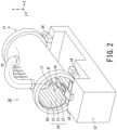
- Fig. 2 is a diagram illustrating the treatment apparatus 10 according to the first embodiment equipped with a rotating gantry 21a of full rotation type.
- the particle beam irradiator 16 is provided with a large number of structures (not shown) such as a vacuum duct, a beam deflection electromagnet, an irradiation field forming electromagnet, various monitors, and a gantry, the particle beam irradiator 16 is considerably heavy.
- a cylindrical rotating gantry 21a (21) of full rotation type as shown in Fig. 2 is used in order to stably support and displace the heavy particle beam irradiator 16.
- Such a rotating gantry 21a is placed on, e.g., rotation drivers 34 that are installed on the base 22, and rotates around the central axis (i.e., Z axis) of the cylinder by the rotation of the rotation driver 34.
- the particle beam irradiator 16 is fixed in such a manner that the tip portion of the particle beam irradiator 16 protrudes toward treatment space 36.
- the rotating gantry 21a By forming the base 22 into a concave shape around the trunk portion of the rotating gantry 21a, the rotating gantry 21a can rotate 360 degrees around the central axis without causing the outer protrusion of the particle beam irradiator 16 to collide with the base 22.
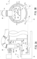
- Fig. 3A is a cross-sectional view of the treatment apparatus 10, a cross-sectional view taken along the central axis of the rotating gantry 21a shown in Fig. 2 .
- Fig. 3B is a cross-sectional view of the treatment apparatus 10, taken along the direction perpendicular to the central axis.
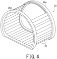
- Fig. 4 is a perspective view illustrating the movable floor 24 provided on the support guides 26a.
- the movable floor 24 is formed by, e.g., juxtaposing a group of longitudinal movable plates 37 along the support guides 26a.
- Each support guide 26a is composed of, e.g., a horizontal portion that is horizontal below the table 18 and a curved portion that is curved along the inner peripheral surface of the rotating gantry 21a and is connected to both ends of the horizontal portion.
- Two support guides 26 formed into the above-described shape are arranged so as to face each other as a pair and are engaged with both end portions in the longitudinal direction of each movable plate 37.
- the movable plates 37 are slidable along the support guides 26a by being engaged with the support guides 26a via, for example, non-illustrated motor-rotating rollers.
- the group of the movable plates 37 below the table 18 forms a horizontal enveloping surface so as to serve as the movable floor 24.
- the term "slide” means that the members contacted to each other move relative to each other keeping the contact.
- “slide” includes relative movement with rollers or gears or sliding on a contacted smooth surface.
- the particle beam irradiator 16 is fixed in such a manner that the tip portion of the particle beam irradiator 16 is inserted into a position sandwiched between the pair of the support guides 26a.
- each support guide 26a is configured as a region where the movable plate 37 does not exist for inserting the tip portion of the particle beam irradiator 16.
- the movable plates 37 are pushed by the particle beam irradiator 16 and slide along the circumferential direction of the particle beam irradiator 16.
- the movable plates 37 are slid in the advancing direction of the particle beam irradiator 16 and are retracted from the occupied area 23 ( Fig. 5 ) by the particle beam irradiator 16.
- the retracting direction of the movable plate 37 may be perpendicular to the circumferential direction of the particle beam irradiator 16.
- plural linear support guides 26b are provided along the central axis of the rotating gantry 21a.
- the sliding driver 35 detects the circumferential angle of the particle beam irradiator 16 around the central axis of the rotating gantry by using a passage sensor 39, and then slides the shaft 41 connected to the movable plates 37 along the support guides 26b.
- the "circumferential angle” is defined as a rotation angle around the central axis of the rotating gantry 21 from the position as zero degree at which the particle beam irradiator 16 stops vertically upward. This definition will be also applied to the following description.
- the movable floor 24 is pulled by the shaft 41 so as to be retracted from the occupied area 23 of the particle beam irradiator 16.
- the rotating gantry 21 is the rotating gantry 21a of full rotation type
- the X-ray generators 27a are fixed to, e.g., the trunk of the rotating gantry 21a.
- the X-ray generators 27a By fixing the X-ray generators 27a to the rotating gantry 21a, the X-ray generators 27a also rotate together with the rotating gantry 21a, and thus the X-ray generators 27a do not collide with the particle beam irradiator 16.
- the non-collision area 31 is (a) the inside of the wall of the trunk of the rotating gantry 21a and (b) a gap between the curved surface of the movable floor 24 and the inner peripheral surface of the trunk of rotating gantry 21a.
- this area is a non-collision area 31 where the X-ray generators 27a do not collide with, for example, the particle beam irradiator 16 without using an electronic position control mechanism.
- the FPDs 27b installed in the particle beam irradiator 16 never collide with the particle beam irradiator 16 and never hinder displacement of the particle beam irradiator 16.
- the vicinity of the tip portion of the particle beam irradiator 16 is the non-collision area 31 within a range in which the FPDs 27b do not hinder the displacement of the particle beam irradiator 16.
- a cover 17 for covering the protruding portion is provided.
- each FPD 27b does not hinder the displacement of the particle beam irradiator 16 and the like.
- the FPDs 27b are equivalent to being provided in the non-collision area 31.
- the FPDs 27b may be housed in the particle beam irradiator 16 or the cover 17.
- the fixed portion of the particle beam irradiator 16 on the inner circumferential surface of the rotating gantry 21a may protrude to be exposed to the treatment space 36.
- the FPDs 27b may be installed in the exposed portion (not shown), and the vicinity of the exposed portion is also the non-collision area 31.
- two pairs of the X-ray imaging devices 27 are installed at an angle of ⁇ 45 degrees from the beam irradiation axis.
- X-ray generators 27a in the treatment space 36 such as in the vicinity of the tip portion of the particle beam irradiator 16 while the FPDs 27b are installed in the rotating gantry 21a like the X-ray generators 27a, namely reversing the positions of the X-ray generators 27a and the FPDs 27b.
- the movable floor 24 is disposed between the X-ray generators 27a and the FPDs 27b.
- the X-rays emitted from the X-ray generators 27a, being shielded by the movable floor 24, do not reach the FPDs 27b on the side opposite to the corresponding X-ray generator 27a with respect to the movable floor 24.
- the movable plate 37 is composed of a first floor member 37a and a second floor member 37b (37) that is different in X-ray transmittance from the first floor member 37a.
- the second floor member 37b as the base material of the movable plate 37 is, e.g., an aluminum alloy (e.g., JISA5052) having a width of about 400 mm and a length of about 2000 mm, and has sufficient strength as a floor surface for the patient 13 to get on and off.
- an aluminum alloy e.g., JISA5052
- the first floor member 37a (37) is made of a material that is higher in X-ray transmittance than the second floor member 37b.
- the ratio ⁇ of the transmittance of the first floor member 37a to the second floor member 37b is selected so as to become larger than 1.
- CFRP carbon-fiber-reinforced plastic
- the material of the first floor member 37a may be the same as that of the second floor member 37b.
- the X-ray transmittance of the first floor member 37a can be increased by reducing the thickness of the first floor member 37a.
- Fig. 6B is a schematic diagram of the movable plate 37 when the movable plate 37 shown in Fig. 6A is irradiated with X-rays.
- the irradiation range of X-rays outputted from the X-ray generator 27a has a certain spread.
- the patient 13 is irradiated with, for example, the minimum amount of X-rays by which the position of the lesion area 19 or a marker embedded around the lesion area 19 can be specified.
- the first floor member 37a is provided in such an area on the movable plate 37 that the intersection plane 30 is included, the intersection plane 30 being the area where the movable plate 37 cuts the irradiation cone area.
- a frame 43 is provided on the first floor member 37a, and the first floor member 37a is coupled to the second floor member 37b via the frame 43.
- the frame 43 is included in the second floor member 37b except for special cases such as a case where a material for transmitting X-rays is selected.
- Coupled includes a case according to the invention as claimed where the second floor member 37b is punched and the first floor member 37a is fit into the punched portion.
- the first floor member 37a When a screw is used for coupling the first floor member 37a, the first floor member 37a can be easily removed, and the X-ray generators 27a can be confirmed without detaching the entire movable plate 37.
- the method for joining the first floor member 37a is not limited to a particular one, and welding or bonding with the use of an adhesive agent other than screw bonding may be used.
- each X-ray generator 27a can be easily taken in and out through this punched portion.
- the movable plate 37 provided with the first floor member 37a has a lower strength than the movable plate 37 that is not provided with the first floor member 37a.
- two pairs of the X-ray imaging devices 27 are often fixed at an angle of ⁇ 45 degrees from the irradiation axis of the particle beam irradiator 16 for the above-described reason.
- the movable floor 24 provided with the first floor members 37a, the movable floor 24 would be provided on the region at an angle of ⁇ 45 ° from the irradiation axis and is also provided on several movable plates 37 in the vicinity of this region.
- a high-quality X-ray image can be acquired with a simple configuration.
- FIG. 7 is a schematic configuration diagram of the treatment apparatus 10 according to the second embodiment.
- a rotating gantry 21b (21) of partial rotation type with the use of, for example, rail tracks 40 or a part of a cylinder.
- Fig. 7 various accompanying devices such as balance weights that are connected to the particle beam irradiator 16 and balance the weight with the particle beam irradiator 16 are omitted.
- the particle beam irradiator 16 is supported by the rotation auxiliary bodies 25 and rotates at an angle smaller than 360 degrees around the patient 13 fixed to the table 18.
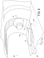
- Fig. 8 is a schematic configuration diagram of the treatment space of the rotation gantry 21b.
- the treatment apparatus 10 of the second embodiment differs from the first embodiment in that it is possible to enter and leave from the position of the trunk of the rotating gantry 21 in a direction perpendicular to the center axis.
- the table 18 is placed close to the base 22 during treatment.
- one of the two X-ray generators 27a is fixed to a portion that is not displaced regardless of the rotation of the rotating gantry 21b, such as the base 22.
- the two X-ray generators 27a in order to acquire the three-dimensional position coordinates of the lesion area 19, it is necessary for the two X-ray generators 27a to be installed with an angle of, e.g., 90 degrees difference.
- the remaining one X-ray generator 27a is arranged at a position so as to face the corresponding FPD 27b with the movable floor 24 interposed between both in a manner similar to the first embodiment.
- the first floor member 37a is provided on the movable plate 37 in a manner similar to the first embodiment so that X-ray imaging can be performed also in the remaining pair of the X-ray imaging devices 27.
- the PDF to be paired with the X-ray generator 27a installed on the base 22 is provided at, e.g., the tip of the particle beam irradiator 16.
- the PDF to be paired with the X-ray generator 27a installed in the rotating gantry 21b is provided on, e.g., the base 22.
- the rotating gantry 21b is a partial rotating type, the same effect as the first embodiment can be obtained.
- the particle beam therapy apparatus of the second embodiment has the same structure as that of the first embodiment except that the rotating gantry 21 is the rotating gantry 21b of partial rotating type, and duplicate description is omitted.
- Fig. 9A and Fig. 9B are schematic cross-sectional views illustrating the treatment apparatus 10 according to the third embodiment.
- Fig. 9A is a cross-sectional view of the treatment apparatus 10 equipped with the rotating gantry 21a of full rotation type shown in Fig. 2 , taken along the central axis of the rotating gantry 21a in a manner similar to Fig. 3A .
- Fig. 9B is a cross-sectional view of the treatment apparatus 10 in the direction perpendicular to the central axis, similarly to Fig. 3B .
- the treatment apparatus 10 in addition to the configuration of the first embodiment, further includes a sensor 44 for detecting the position of the first floor member 37a and a position adjuster 46 that slides the movable plates 37 on the basis of the position of the first floor member 37a so as to arrange the first floor member 37a on the irradiation area of the X-ray imaging devices 27.
- the X-ray generators 27a When the X-ray generators 27a are installed in the rotating gantry 21a of full rotation type, the X-ray generators 27a rotate around the central axis in a substantially perfect circle.
- the movable floor 24 moves along the support guides 26a, the movable floor 24 also forms a curved portion and a horizontal portion.
- the length of the movable floor 24 with respect to the central angle of rotation is shorter than the curved portion.
- the first floor member 37a having the circumferential angle difference of 45 degrees at a certain circumferential angle may deviate from the irradiation area of the X-ray generators 27a at another circumferential angle.
- the first floor members 37a are usually provided on respective two or more adjacent movable plates 37.
- the frames 43 shield the X-rays, and thus the marker and the characteristic bone portion cannot be properly specified in some cases.
- the movable floor 24 is not connected to the particle beam irradiator 16, and has a margin for sliding on the support guides 26a independently of the particle beam irradiator 16.
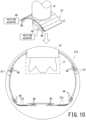
- Fig. 10 is a schematic cross-sectional view of moving sheets 47 provided in the treatment apparatus 10 according to the third embodiment.
- the movable plates 37 are divided into plural groups, each of which is composed of several movable plates 37 as shown in Fig. 10 .
- Adjacent movable plates 37 in each group are movably connected with each other while keeping a distance between them in such a manner that the respective group form plural moving sheets 47.
- Each moving sheet 47 is overlapped at both ends on adjacent moving sheets 47, and one or more than one of the moving sheets 47 is engaged with the support guides 26a.
- the support guides 26a are provided with two lanes composed of the inner-circumferential-side lane and the outer-circumferential-side lane (not shown).
- the adjacent moving sheets 47 are alternately engaged with the inner-circumferential-side lane and the outer-circumferential-side lane.
- Adjacent moving sheets 47 are slidably connected to each other with back rollers 48 in such a manner that each moving sheet 47 overlaps to the other moving sheet 47 at one end and overlaps the other moving sheet 47 adjacent at the other end for preventing occurrence of a gap.
- one or some of the plural moving sheets 47 is fixedly connected to the trunk of the particle beam irradiator 16.
- the sensor 44 positioned at an immovable portion such as the base 22 is installed facing towards the moving sheets 47 engaged with each other in the above-described manner, and detects the positions of the respective first floor members 37a.
- the senor 44 may be installed near the tip of the particle beam irradiator 16.
- a detection method for instance, there is a method of sticking a fluorescent sticker to the frame 43 and optically detecting the reflection of the fluorescent sticker.
- the relationship between the circumferential angle of the first floor member 37a and the circumferential angle at which the particle beam irradiator 16 stops may be memorized in advance so that the memorized relationship is used for calculating angle correction amount corresponding to the detected circumferential angle of the stopped position of the particle beam irradiator 16.
- the information is sent to the position adjuster 46 and the position adjuster 46 performs correction processing such that the first floor member 37a positionally coincides to the irradiation area of the X-ray generators 27a.
- the angle correction amount it is preferable to perform the calculation such that the gap between the moving sheets 47 at the horizontal portion of the movable floor 24 becomes as small as possible.
- each moving sheet 47 it is desirable to provide a guard such as a roll screen at each end of the moving sheets 47 in the horizontal portion in order to prevent small objects from dropping or getting caught when the gap is formed. Further, it is preferable to drive each moving sheet 47 so as not to generate a gap in the horizontal portion as much as possible.
- the position adjuster 46 slides the moving sheets 47 on the basis of the relative circumferential angle between the FPDs 27b and the X-ray generators 27a so as to dispose the first floor member 37a on the irradiation area.
- the X-ray generator 27a and the first floor member 37a can be made to coincide at an arbitrary circumferential angle as described above, it is possible to perform X-ray imaging from an arbitrary circumferential angle.
- the output directions of X-rays are set to the horizontal direction and the vertical direction.
- the respective positions of the first floor members 37a are detected by the sensor 44 and the respective circumferential angles of the first floor members 37a are adjusted so as to match the respective circumferential angles of the X-ray generators 27a.
- X-ray imaging is performed.
- X-rays pass through the first floor members 37a, further pass through the vicinity of the lesion area 19 of the patient 13, and are detected by the FPDs 27b fixed to the particle beam irradiator 16.
- the position of the patient 13 is adjusted on the basis of the acquired X-ray image in such a manner that the particle beam B can be accurately radiated onto the lesion area 19 having been set in treatment planning.
- a technician checks the X-ray image acquired in the step S15 and adjusts the position of the patient 13 based on the check result.
- the processing of the steps S15 and S16 is repeated until the position of the patient 13 becomes appropriate.
- the technician 38 gets on the movable floor 24 to access the patient 13 in order to check the posture and condition of the patient 13 in some cases.
- the positioning processing of the steps S15 and S16 is completed.
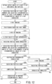
- step S17 the particle beam irradiator 16 is rotated and placed at the output position.
- the sensor 44 detects the respective positions of the first floor members 37a and the first floor members 37a are caused to slide such that the respective circumferential angles of the first floor members 37a match the respective circumferential angles of the X-ray generators 27a.
- the first floor members 37a are included in the X-ray irradiation area.
- next step S19 it is determined as to whether respiration synchronized irradiation is performed or not.
- the processing proceeds to the step S20 in which the particle beam irradiator 16 directly radiates the particle beam B.
- step S21 after irradiation of a predetermined dose according to the treatment plan, the irradiation is completed and the processing proceeds to the step S22.
- next step S22 it is determined as to whether irradiation is performed by another circumferential angle or not.
- the particle beam irradiator 16 is rotated and arranged at the next circumferential angle and the processing returns to the step S17.
- the determination result is negative, i.e., irradiation by every circumferential angle in the treatment plan is completed, the particle beam therapy is completed.
- respiration synchronized irradiation method in which the particle beam B is radiated at a timing adjusted to the periodic displacement of the lesion area 19 due to respiration of the patient 13.
- step S19 When it is determined in the step S19 that the respiration synchronized irradiation is performed, the processing proceeds to the step S23 in which X-ray imaging is performed for checking the position of the lesion area 19.
- next step S24 when the lesion area 19 comes to the optimum position, the particle beam B is radiated at the adjusted timing such that X-ray imaging and irradiation of the particle beam B are repeated until it is determined in the next step S25 that the irradiation is completed.
- the processing proceeds to the step S22 in which the rotating gantry 21a is rotated so as to move the particle beam irradiator 16 to another circumferential angle similarly to the ordinary irradiation treatment method.
- X-ray imaging can be satisfactorily performed without returning the circumferential angle of the particle beam irradiator 16 to the initial angle (positioning angle), by adjusting the respective circumferential angles of the first floor members 37a in accordance with the circumferential angle of the stopped particle beam irradiator 16 as described above.
- Position confirmation and treatment resumption can be performed in a short time without rotation of the particle beam irradiator 16 and without a drive system of the X-ray imaging devices.
- the third embodiment can be similarly applied to the rotating gantry 21b of partial rotation type.
- the particle beam therapy apparatus of the third embodiment has the same structure and the same operation procedure as those of the first embodiment except that the movable floor 24 is divided into moving sheets 47 and the stopped circumferential angle is corrected. Thus, duplicate description is omitted.
- the treatment apparatus 10 of the third embodiment in addition to the effect of the first embodiment, it is possible to match the X-ray generators 27a with the first floor members 37a at an arbitrary circumferential angle, and thus X-ray imaging can be performed at an arbitrary circumferential angle.
- the treatment time can also be shortened.
- respiration synchronized irradiation is performed by synchronizing the shift of the lesion area 19 caused by breathing and/or change in posture of the patient 13 during irradiation of the particle beam, and the moving object tracking irradiation is performed by following the above-described shift of the lesion area 19.
- X-ray imaging can be performed from an arbitrary circumferential angle
- X-ray irradiation can be performed from the optimum circumferential angle in relation to the lesion area 19.
- Fig. 11A is a perspective view of the movable plates 37 of the treatment apparatus 10 according to the fourth embodiment.
- Fig. 11B is a cross-sectional view taken along the line I-I in Fig. 11A , i.e., a cross-sectional view of the second floor member 37b.
- Fig. 11C is a cross-sectional view taken along line II-II in Fig. 11A , i.e. , a cross-sectional view of the first floor member 37a.
- the first floor members 37a provided on two or more movable plates 37 adjacent to each other in the circumferential direction are continuously disposed without interposing the second floor member 37b between the first floor members 37a.
- the first floor members 37a are continuously disposed in the circumferential direction without including the frames 43 ( Fig. 6 ) shown in the first embodiment.
- each first floor member 37a is connected to the two parts of the second floor member 37b that is divided into the two parts along the circumferential direction.
- a rib (not shown) may be provided at each joint between the first floor member 37a and the second floor member 37b so as to join the first floor member 37a to the second floor member 37b.
- the continuously arranged first floor members 37a have, e. g. , an L shape or a U shape so as to fit the shape of each second floor member 37b in some cases.
- the transmission path length of X-rays changes abruptly and discontinuously in a case where the incident point of X-rays on the first floor members 37a and the incident angle of X-rays on the first floor members 37a continuously change.
- each first floor member 37a has a sharp shape such as a right-angled shape, due to a continuous change in relative angle between each first floor member 37a and each X-ray generator 27a, the transmission path length suddenly changes discontinuously.
- each first floor member 37a is formed into such a shape that the transmission path length of X-rays entering each first floor member 37a does not suddenly change even when the positional relationship between each first floor member 37a and each X-ray generator 27a changes.
- each apex angle of each first floor member 37a is as smooth and gently bent as possible.
- each first floor member 37a is made as flat as possible to make the thickness of the first floor member 37a unchanged.
- each bent end portion of each first floor member 37a it is preferable for each bent end portion of each first floor member 37a that the length of the bent portion is as short as possible.
- each first floor member 37a preferably has such a shape that its length does not exceed the length determined as the allowable upper limit for X-rays made incident from an arbitrary relative position that the first floor member 37a and the X-ray generator 27a can take.
- the particle beam therapy apparatus of the fourth embodiment has the same structure and the same operation procedure as those of the first embodiment except that the first floor members 37a are continuously arranged without providing the frames 43 and the shape of each movable plate 37 is defined. Thus, duplicate description is omitted.
- X-ray imaging can be performed without using the sensor 44 and the position adjuster 46 for performing angle correction of the relative position between the movable floor 24 and each X-ray generator 27a.
- the treatment apparatus 10 or the particle beam therapy method of at least one embodiment as described above by providing the first floor member 37a on the movable plate 37, it is possible to acquire a high-quality X-ray image with a simple configuration and shorten the treatment time.
Landscapes
- Health & Medical Sciences (AREA)
- Life Sciences & Earth Sciences (AREA)
- Engineering & Computer Science (AREA)
- Medical Informatics (AREA)
- Biomedical Technology (AREA)
- Animal Behavior & Ethology (AREA)
- Veterinary Medicine (AREA)
- Nuclear Medicine, Radiotherapy & Molecular Imaging (AREA)
- Public Health (AREA)
- Pathology (AREA)
- Radiology & Medical Imaging (AREA)
- General Health & Medical Sciences (AREA)
- Heart & Thoracic Surgery (AREA)
- Molecular Biology (AREA)
- Surgery (AREA)
- Physics & Mathematics (AREA)
- Biophysics (AREA)
- Optics & Photonics (AREA)
- High Energy & Nuclear Physics (AREA)
- Dentistry (AREA)
- Oral & Maxillofacial Surgery (AREA)
- Radiation-Therapy Devices (AREA)
Description
- Embodiments of the present invention relate to a particle beam therapy apparatus (i.e., particle beam therapy device) equipped with a rotating gantry.
- In cancer treatment in recent years, a particle beam therapy method is widely used. In the particle beam therapy method, a cancer lesion area is irradiated with a particle beam that is generated by accelerating charged particles such as protons and carbon ions to high energy.
- In the particle beam therapy method, in order to irradiate a cancer lesion area with a particle beam without irradiating important organs, it is required to perform irradiation changing the irradiation angle of the beam variously. Thus, for instance, a particle beam irradiator is fixed to a cylindrical rotating gantry to rotate together, thereby is changed its irradiation angle.
- The inner space of the rotating gantry serving as a treatment room is provided with a movable floor that maintains a flat horizontal floor surface regardless of the rotation of the rotating gantry.
- By using the movable floor, a technician accesses a patient before and after treatment and the patient comes down from the treatment table in case of emergency.
- In order not to hinder the displacement of a tip portion of a particle beam irradiator which is fixed to the treatment room to protrude its tip portion into the treatment room, the movable floor slides in accordance with the displacement of the tip portion.
- Before or during the irradiation of the particle beam, X-ray imaging is performed so that the position and shape of the lesion area are accurately analyzed.
- Thus, an X-ray generator for radiating X-rays toward the patient and an X-ray detector for detecting X-rays transmitted through the patient (hereinafter, both are referred to as "X-ray imaging devices") are arranged in the treatment space.
- Since a particle beam therapy apparatus is equipped with some devices that change their relative positions as described above, it is necessary to consider the changes of the relative arrangements of the X-ray imaging devices.
- For instance, there is a known method of connecting arms with the X-ray imaging devices and storing the arms together with the X-ray imaging devices at a place that the arms and the X-ray imaging devices do not collide with any other device in the treatment room.
- In this case, the arms being controlled so as not to hinder the replacements of other devices, the X-ray generator is placed in the vicinity of the lesion area only at the time of X-ray irradiation, and after the completion of imaging, the X-ray generators are retracted.
- However, the above-described technique has a problem that the arms and their control mechanisms complicate the particle beam therapy apparatus and the treatment time is prolonged by the arrangement time and retraction time of the X-ray imaging devices.
- Nevertheless, X-ray images acquired by X-ray imaging are required to be clear to the extent that the position of the lesion area can be accurately specified.
-
- [Patent Document 1]
JP 3519248 B - [Patent Document 2]
JP 3927348 B - [Patent Document 3]
JP 4130680 B - [Patent Document 4]
EP 3251600 A1 . This document forms prior art in accordance with Art.54 (3) and discloses a radiographic imaging apparatus which is configured so that an irradiation device is mounted on a rotary drum of a rotary gantry and a pair of X-ray sources are disposed outside the rotary drum attached to the outside surface of the rotary drum. A pair of X-ray detection devices (FPDs) facing the respective X-ray sources is mounted in the irradiation device. A movable floor of a therapy cage includes a number of footboards which are formed of a steel plate or other metal plate, and two X-ray transmission plates and is disposed between a stationary ring rail and a movable ring rail. The X-ray transmission plates are disposed between adjacent footboards within the movable floor and X-rays are not transmitted through the footboards but only through the X-ray transmission plates. The transmission plates each include a metal plate which is formed, for example, of an aluminum alloy and an X-ray transmission portion through which X-rays are transmitted. The X-ray transmission portion is, for example, a rectangular graphite plate, reinforced glass, plastic or other X-ray permeable, non-metallic member which is fitted into an opening that is formed in the metal plate and is of the same size as the X-ray transmission portion and is attached integrally to the metal plate. - [Patent Document 5]
WO 2010/076270 A1 . This document discloses a medical apparatus for particle therapy wherein an irradiation unit is able to move inside a patient enclosure together with an imaging device that includes an X-ray beam generator and a detector, wherein one of the X-ray beam generators is included in a nozzle while a second one is located within a gantry. A hole is drilled in a primary plate of a rolling floor located in front of the X-ray tube to ensure the passing of the X-ray beam through the floor. - [Patent Document 6]
US 2008/031511 A1 . The document discloses a particle therapy system which includes a rotatable gantry with a gantry wall that surrounds an interior and a small irradiation chamber with an irradiation chamber wall that is located inside the interior. The irradiation chamber wall includes a plurality of wall elements which, to enlarge the irradiation chamber, are adjustable in the direction of the deflection chamber and the wall elements are supported by hinges. The document is silent as to specific structure of the wall elements with respect to the transmission of X-rays since the entire document does not mention the provision of X-ray imaging devices in the therapy system. - [Patent Document 7]
US 2011/0024645 A1 . The document discloses a rotating irradiation apparatus which includes a radiation device that irradiates a charged particle beam, a frame on which the irradiation device is mounted and which can rotate the irradiation device so that a patient lying on a treatment table fixed to a stationary floor surface is irradiated with the charged particle beam. The document is silent as to the provision of a X-ray generating device in such irradiation apparatus and does not disclose the structure of plate elements for the transmission of X-rays in particular. - [Patent Document 8]
WO 2006/076545 A3 . The document discloses a moveable floor system for use with a rotating gantry in a radiation treatment facility. This document, too, is silent as to the structure of plates of the floors in the system for the transmission of X-rays and specifically for the purpose of taking in and out of a X-ray generator through an opening in a plate of the floor. - An object of the present invention is to provide a particle beam therapy apparatus that can acquire a high-quality X-ray image with a simple structure and shorten treatment time.
- A particle beam therapy apparatus according to the invention has the features of claim 1 and inter alia includes: a particle beam irradiator configured to output a particle beam; a supporting structure configured to be movable and support the particle beam irradiator; a plurality of movable plates disposed on a displacement trajectory of the particle beam irradiator, forming a substantially horizontal enveloping surface below a table for placing an irradiation object, and including a first floor member and a second floor member in at least one of the plurality of movable plates, the first floor member being made of a material that is higher in X-ray transmittance than the second floor member; an X-ray generator provided in a non-collision area where the X-ray generator does not collide with any of the particle beam irradiator, the supporting structure, and the plurality of movable plates; and an X-ray detector installed at a position where the X-ray detector faces the X-ray generator and detects X-rays transmitted through the first floor member. The second floor member is punched and the first floor member is removably fit into the punched portion, thereby coupling the first floor member to the second floor member, and the size of the punched portion is set such that the X-ray generator can be taken in and out through the punched portion when the first floor member is removed.
-
-
Fig. 1 is a schematic configuration diagram of a particle beam therapy apparatus according to one embodiment. -
Fig. 2 is a diagram illustrating the particle beam therapy apparatus equipped with a rotating gantry of full rotation type according to the first embodiment. -
Fig. 3A is a cross-sectional view of the particle beam therapy apparatus according to the first embodiment, taken along the central axis of the rotating gantry. -
Fig. 3B is a cross-sectional view of the particle beam therapy apparatus according to the first embodiment, taken along the direction perpendicular to the central axis of the rotating gantry. -
Fig. 4 is a perspective view illustrating a movable floor provided on a support guide. -
Fig. 5 is a top view illustrating a movable floor of lateral sliding type as a modification. -
Fig. 6A is a perspective view illustrating each movable plate of the particle beam therapy system according to the first embodiment. -
Fig. 6B is a schematic diagram illustrating a case where X-rays are radiated onto the movable plate shown inFig. 6A . -
Fig. 7 is a schematic configuration diagram of the particle beam therapy system according to the second embodiment. -
Fig. 8 is a schematic configuration diagram of treatment space of a rotating gantry of partial rotation type. -
Fig. 9A is a cross-sectional view of the particle beam therapy apparatus according to the third embodiment, taken along the central axis of its rotating gantry. -
Fig. 9B is a cross-sectional view of the particle beam therapy apparatus according to the third embodiment, taken along the direction perpendicular to the central axis of the rotating gantry. -
Fig. 10 is a schematic cross-sectional view of moving sheets included in the particle beam therapy apparatus according to the third embodiment. -
Fig. 11A is a perspective view of movable plates included in the particle beam therapy apparatus according to the fourth embodiment. -
Fig. 11B is a cross-sectional view taken along the line I-I inFig. 11A . -
Fig. 11C is a cross-sectional view taken along line II-II inFig. 11A . -
Fig. 12 is a flowchart illustrating an operation procedure of the particle beam therapy apparatus according to the third embodiment. - Hereinafter, embodiments of the present invention will be described with reference to the accompanying drawings.
-
Fig. 1 is a schematic configuration diagram of the particle beam therapy apparatus 10 (hereinafter simply referred to as the treatment apparatus 10) according to one embodiment. - Charged particles such as protons or carbon ions emitted from an
ion source 11 form a particle beam B accelerated by aparticle beam accelerator 12. - The particle beam B is guided with magnetic field to a
treatment building 14 where a patient 13 as an irradiation object is present. - Further, the particle beam B is guided to a
particle beam irradiator 16 that is connected to theaccelerator 12 via a rotary joint 20, and then is outputted toward thelesion area 19 of the patient 13 fixed to the table 18 from the tip portion of theparticle beam irradiator 16. - In order to maintain the posture of the
particle beam irradiator 16 that variously changes its irradiation angle, theparticle beam irradiator 16 is supported by a rotatinggantry 21. - The rotating
gantry 21 is a rotating structure provided as a supporting structure for supporting theparticle beam irradiator 16. - The
particle beam irradiator 16 can take various postures subjecting the displacement, such as rotation, of therotating gantry 21 with respect to thetreatment building 14. - As to the table 18 placed on a treatment mount that is fixed to a base 22 built in the
treatment building 14, the table 18 can also change the posture within such a range that excessive load is not exerted on thepatient 13. - Since a person involved, such as the patient 13 or a technician 38 (
Fig. 3B ), accesses the periphery of the table 18, a floor surface configured to keep horizontality regardless of displacement of therotating gantry 21 is disposed below the table 18. - When the portion of the floor surface disposed in the passing trajectory of the
particle beam irradiator 16 is not displaced, the displacement of theparticle beam irradiator 16 is hindered. - For this reason, at least the floor surface in the passing trajectory needs to be configured to be a
movable floor 24 that is retracted from an occupied area 23 (Fig. 5 ) to be occupied by theparticle beam irradiator 16 in accordance with passage of theparticle beam irradiator 16. - The
movable floor 24 slides by being fixed to the base 22 directly or via the floor surface or by being slidably engaged with support guides 26a disposed inside the rotatinggantry 21. - Details of the
movable floor 24 will be described below. - Further, the
treatment apparatus 10 is equipped withX-ray generators 27a (27) andX-ray detectors 27b (27). EachX-ray generator 27a is installed so as to face thepatient 13 and emits X-rays, and eachX-ray detector 27b (i.e., Flat Panel Detector: FPD) detects X-rays transmitted through thepatient 13. - Hereinafter, these
X-ray generators 27a and theFPDs 27b are arbitrarily and collectively referred to as X-ray imaging devices 27. - In order to shot the periphery of the
lesion area 19 clearly by using X-rays, the X-ray imaging devices 27 need to be placed on or near the passage trajectory of theparticle beam irradiator 16 at least at the time of X-ray imaging. - For this reason, in the
treatment apparatus 10 according to the present embodiment, the respective X-ray imaging devices 27 are fixed and installed at such positions in anon-collision area 31 that eachX-ray generator 27a faces the correspondingFPD 27b with themovable floor 24 interposed between both. - The
non-collision area 31 is an area where the X-ray imaging devices 27 do not collide with any of theparticle beam irradiator 16, the rotatinggantry 21, and themovable floor 24 without using an electronic position control mechanism. - Hereinafter, embodiments of the
treatment apparatus 10 shown inFig. 2 to Fig. 12 will be described including the description of thenon-collision area 31. -
Fig. 2 is a diagram illustrating thetreatment apparatus 10 according to the first embodiment equipped with arotating gantry 21a of full rotation type. - Since the
particle beam irradiator 16 is provided with a large number of structures (not shown) such as a vacuum duct, a beam deflection electromagnet, an irradiation field forming electromagnet, various monitors, and a gantry, theparticle beam irradiator 16 is considerably heavy. - Thus, in many cases, a cylindrical
rotating gantry 21a (21) of full rotation type as shown inFig. 2 is used in order to stably support and displace the heavyparticle beam irradiator 16. - Such a
rotating gantry 21a is placed on, e.g.,rotation drivers 34 that are installed on thebase 22, and rotates around the central axis (i.e., Z axis) of the cylinder by the rotation of therotation driver 34. - The
particle beam irradiator 16 is fixed in such a manner that the tip portion of theparticle beam irradiator 16 protrudes towardtreatment space 36. - By forming the base 22 into a concave shape around the trunk portion of the
rotating gantry 21a, therotating gantry 21a can rotate 360 degrees around the central axis without causing the outer protrusion of theparticle beam irradiator 16 to collide with thebase 22. -
Fig. 3A is a cross-sectional view of thetreatment apparatus 10, a cross-sectional view taken along the central axis of therotating gantry 21a shown inFig. 2 . -
Fig. 3B is a cross-sectional view of thetreatment apparatus 10, taken along the direction perpendicular to the central axis. -
Fig. 4 is a perspective view illustrating themovable floor 24 provided on the support guides 26a. - As shown in
Fig. 3A andFig. 4 , themovable floor 24 is formed by, e.g., juxtaposing a group of longitudinalmovable plates 37 along the support guides 26a. - Each
support guide 26a is composed of, e.g., a horizontal portion that is horizontal below the table 18 and a curved portion that is curved along the inner peripheral surface of therotating gantry 21a and is connected to both ends of the horizontal portion. - Two support guides 26 formed into the above-described shape are arranged so as to face each other as a pair and are engaged with both end portions in the longitudinal direction of each
movable plate 37. - The
movable plates 37 are slidable along the support guides 26a by being engaged with the support guides 26a via, for example, non-illustrated motor-rotating rollers. - The group of the
movable plates 37 below the table 18 forms a horizontal enveloping surface so as to serve as themovable floor 24. - In the present description, the term "slide" means that the members contacted to each other move relative to each other keeping the contact.
- For instance, "slide" includes relative movement with rollers or gears or sliding on a contacted smooth surface.
- The
particle beam irradiator 16 is fixed in such a manner that the tip portion of theparticle beam irradiator 16 is inserted into a position sandwiched between the pair of the support guides 26a. - That is, a part of the entire circumference of each
support guide 26a is configured as a region where themovable plate 37 does not exist for inserting the tip portion of theparticle beam irradiator 16. - When the
particle beam irradiator 16 is rotated by the rotation of therotating gantry 21a, themovable plates 37 are pushed by theparticle beam irradiator 16 and slide along the circumferential direction of theparticle beam irradiator 16. - In other words, the
movable plates 37 are slid in the advancing direction of theparticle beam irradiator 16 and are retracted from the occupied area 23 (Fig. 5 ) by theparticle beam irradiator 16. - As shown in
Fig. 5 illustrating the top view of amovable floor 24 of lateral sliding type as a modification ofmovable floor 24, the retracting direction of themovable plate 37 may be perpendicular to the circumferential direction of theparticle beam irradiator 16. - In the case of the
movable floor 24 of lateral sliding type, for instance, plural linear support guides 26b are provided along the central axis of therotating gantry 21a. - Further, the sliding
driver 35 detects the circumferential angle of theparticle beam irradiator 16 around the central axis of the rotating gantry by using apassage sensor 39, and then slides the shaft 41 connected to themovable plates 37 along the support guides 26b. - The "circumferential angle" is defined as a rotation angle around the central axis of the
rotating gantry 21 from the position as zero degree at which theparticle beam irradiator 16 stops vertically upward. This definition will be also applied to the following description. - The
movable floor 24 is pulled by the shaft 41 so as to be retracted from the occupiedarea 23 of theparticle beam irradiator 16. - When the
rotating gantry 21 is therotating gantry 21a of full rotation type, theX-ray generators 27a are fixed to, e.g., the trunk of therotating gantry 21a. - By fixing the
X-ray generators 27a to therotating gantry 21a, theX-ray generators 27a also rotate together with therotating gantry 21a, and thus theX-ray generators 27a do not collide with theparticle beam irradiator 16. - In other words, the
non-collision area 31 is (a) the inside of the wall of the trunk of therotating gantry 21a and (b) a gap between the curved surface of themovable floor 24 and the inner peripheral surface of the trunk ofrotating gantry 21a. - That is, this area is a
non-collision area 31 where theX-ray generators 27a do not collide with, for example, theparticle beam irradiator 16 without using an electronic position control mechanism. - In this case, when the
FPD 27b is provided at the tip portion of theparticle beam irradiator 16, the relative angle between eachFPD 27b and thecorresponding X-ray generator 27a does not change and the installation angle of the X-ray detection plane can be fixed. - The
FPDs 27b installed in theparticle beam irradiator 16 never collide with theparticle beam irradiator 16 and never hinder displacement of theparticle beam irradiator 16. - In other words, when the
FPDs 27b are fixed to theparticle beam irradiator 16, the vicinity of the tip portion of theparticle beam irradiator 16 is thenon-collision area 31 within a range in which theFPDs 27b do not hinder the displacement of theparticle beam irradiator 16. - On the protruding portion of the
particle beam irradiator 16 protruding toward the inside of therotating gantry 21a, acover 17 for covering the protruding portion is provided. - Even when each
FPD 27b is provided on the inner surface or the outer surface of thecover 17, eachFPD 27b does not hinder the displacement of theparticle beam irradiator 16 and the like. - Thus, even when the respective FPD s27b are provided on the inner surface and the outer surface of the
cover 17, theFPDs 27b are equivalent to being provided in thenon-collision area 31. - Even when the installation angle can be fixed, the
FPDs 27b may be housed in theparticle beam irradiator 16 or thecover 17. - The fixed portion of the
particle beam irradiator 16 on the inner circumferential surface of therotating gantry 21a may protrude to be exposed to thetreatment space 36. - In this case, the
FPDs 27b may be installed in the exposed portion (not shown), and the vicinity of the exposed portion is also thenon-collision area 31. - Preferably, two pairs of the X-ray imaging devices 27 are installed at an angle of ± 45 degrees from the beam irradiation axis.
- By acquiring respective X-ray images from two directions, it is possible to grasp the three-dimensional position of the
lesion area 19. - In addition, installing the respective two pairs of the X-ray imaging devices 27 in the horizontal direction and the vertical direction makes it possible to use an image processing method common to the conventional fixed irradiation chamber.
- Further, it is possible to install
X-ray generators 27a in thetreatment space 36 such as in the vicinity of the tip portion of theparticle beam irradiator 16 while theFPDs 27b are installed in therotating gantry 21a like theX-ray generators 27a, namely reversing the positions of theX-ray generators 27a and theFPDs 27b. - Although it is not specifically shown, the respective positions of the
X-ray generators 27a and theFPDs 27b can be exchanged in all the following embodiments. - As described above, when the
X-ray generators 27a are installed in therotating gantry 21a and theFPDs 27b are installed in, for example, theparticle beam irradiator 16, themovable floor 24 is disposed between theX-ray generators 27a and theFPDs 27b. - In other words, the X-rays emitted from the
X-ray generators 27a, being shielded by themovable floor 24, do not reach the FPDs 27b on the side opposite to thecorresponding X-ray generator 27a with respect to themovable floor 24. - For this reason, as illustrated by the
movable plate 37 inFig. 6A , themovable plate 37 is composed of afirst floor member 37a and asecond floor member 37b (37) that is different in X-ray transmittance from thefirst floor member 37a. - The
second floor member 37b as the base material of themovable plate 37 is, e.g., an aluminum alloy (e.g., JISA5052) having a width of about 400 mm and a length of about 2000 mm, and has sufficient strength as a floor surface for the patient 13 to get on and off. - The
first floor member 37a (37) is made of a material that is higher in X-ray transmittance than thesecond floor member 37b. - In other words, the ratio η of the transmittance of the
first floor member 37a to thesecond floor member 37b is selected so as to become larger than 1. - For instance, carbon-fiber-reinforced plastic (CFRP) has high strength against X-ray transmittance and is suitable as a material for the
first floor member 37a. - It is known that the X-ray transmittance of CFRP is about 5 times larger than that of aluminum of the same thickness.
- The material of the
first floor member 37a may be the same as that of thesecond floor member 37b. - Even when the
first floor member 37a and thesecond floor member 37b are made of the same material, the X-ray transmittance of thefirst floor member 37a can be increased by reducing the thickness of thefirst floor member 37a. -
Fig. 6B is a schematic diagram of themovable plate 37 when themovable plate 37 shown inFig. 6A is irradiated with X-rays. - The irradiation range of X-rays outputted from the
X-ray generator 27a has a certain spread. - It is sufficient that the
patient 13 is irradiated with, for example, the minimum amount of X-rays by which the position of thelesion area 19 or a marker embedded around thelesion area 19 can be specified. - In other words, a part of X-rays emitted from the
X-ray generator 27a reaches the patient 13, and then is detected by theFPD 27b. - For this reason, as shown in
Fig. 6B , thefirst floor member 37a is provided in such an area on themovable plate 37 that theintersection plane 30 is included, theintersection plane 30 being the area where themovable plate 37 cuts the irradiation cone area. - As shown in
Fig. 6B , for instance, aframe 43 is provided on thefirst floor member 37a, and thefirst floor member 37a is coupled to thesecond floor member 37b via theframe 43. - It is assumed that the
frame 43 is included in thesecond floor member 37b except for special cases such as a case where a material for transmitting X-rays is selected. - The term "coupled" as used herein includes a case according to the invention as claimed where the
second floor member 37b is punched and thefirst floor member 37a is fit into the punched portion. - When a screw is used for coupling the
first floor member 37a, thefirst floor member 37a can be easily removed, and theX-ray generators 27a can be confirmed without detaching the entiremovable plate 37. - The method for joining the
first floor member 37a is not limited to a particular one, and welding or bonding with the use of an adhesive agent other than screw bonding may be used. - In addition, by setting the size of the punched portion one size larger than that of each
X-ray generator 27a, eachX-ray generator 27a can be easily taken in and out through this punched portion. - In many cases, the
movable plate 37 provided with thefirst floor member 37a has a lower strength than themovable plate 37 that is not provided with thefirst floor member 37a. - For this reason, it is desirable to provide the
first floor member 37a only on the minimized number of specificmovable plates 37. - For instance, two pairs of the X-ray imaging devices 27 are often fixed at an angle of ± 45 degrees from the irradiation axis of the
particle beam irradiator 16 for the above-described reason. - Thus, as for the
movable floor 24 provided with thefirst floor members 37a, themovable floor 24 would be provided on the region at an angle of ± 45 ° from the irradiation axis and is also provided on severalmovable plates 37 in the vicinity of this region. - As described above, according to the
treatment apparatus 10 of the first embodiment, a high-quality X-ray image can be acquired with a simple configuration. - In addition, since it is not necessary to retract the X-ray imaging devices 27, treatment time can be shortened.
-
FIG. 7 is a schematic configuration diagram of thetreatment apparatus 10 according to the second embodiment. - In recent years, as shown in
Fig. 7 , there is known arotating gantry 21b (21) of partial rotation type with the use of, for example,rail tracks 40 or a part of a cylinder. - In
Fig. 7 , various accompanying devices such as balance weights that are connected to theparticle beam irradiator 16 and balance the weight with theparticle beam irradiator 16 are omitted. - In the
rotating gantry 21b shown inFig. 7 , tworail tracks 40 in a curved shape and in an angle range smaller than 360 degrees are provided. - Two rotation
auxiliary bodies 25 are engaged with these two rail tracks 40. - The
particle beam irradiator 16 is supported by the rotationauxiliary bodies 25 and rotates at an angle smaller than 360 degrees around thepatient 13 fixed to the table 18. - In the case of using the
rotating gantry 21b, by limiting the displacement angle of theparticle beam irradiator 16 and horizontally rotating the table 18, it is possible to radiate the particle beam B from an arbitrary angle in the same manner as therotating gantry 21a of full rotation type. - By limiting the displacement angle, it is possible to secure a
large non-collision area 31 in the vicinity of the table 18. - In the second embodiment, a description will be given of the case where the
treatment apparatus 10 is applied to therotation gantry 21b of partial rotation type. -
Fig. 8 is a schematic configuration diagram of the treatment space of therotation gantry 21b. - As shown in
Fig. 8 , thetreatment apparatus 10 of the second embodiment differs from the first embodiment in that it is possible to enter and leave from the position of the trunk of therotating gantry 21 in a direction perpendicular to the center axis. - Thus, the table 18 is placed close to the base 22 during treatment.
- Accordingly, for instance, one of the two
X-ray generators 27a is fixed to a portion that is not displaced regardless of the rotation of therotating gantry 21b, such as thebase 22. - When X-rays are emitted from the
X-ray generator 27a fixed to thebase 22, the X-rays emitted to theFPD 27b are radiated onto thepatient 13 without being shielded by themovable floor 24. - Thus, as to the X-ray imaging devices 27 including the
X-ray generator 27a fixed to thebase 22, contrivance like the first embodiment is unnecessary for themovable plates 37. - However, as described above, in order to acquire the three-dimensional position coordinates of the
lesion area 19, it is necessary for the twoX-ray generators 27a to be installed with an angle of, e.g., 90 degrees difference. - Thus, even with the
rotation gantry 21b of partial rotation type, the remaining oneX-ray generator 27a is arranged at a position so as to face the correspondingFPD 27b with themovable floor 24 interposed between both in a manner similar to the first embodiment. - Hence, the
first floor member 37a is provided on themovable plate 37 in a manner similar to the first embodiment so that X-ray imaging can be performed also in the remaining pair of the X-ray imaging devices 27. - Although it is not shown, the PDF to be paired with the
X-ray generator 27a installed on thebase 22 is provided at, e.g., the tip of theparticle beam irradiator 16. - Further, the PDF to be paired with the
X-ray generator 27a installed in therotating gantry 21b is provided on, e.g., thebase 22. - As described above, according to the second embodiment, even when the
rotating gantry 21b is a partial rotating type, the same effect as the first embodiment can be obtained. - Note that the particle beam therapy apparatus of the second embodiment has the same structure as that of the first embodiment except that the rotating
gantry 21 is therotating gantry 21b of partial rotating type, and duplicate description is omitted. - The same reference signs are assigned to the same components in terms of configuration or function as the first embodiment in each figure, and duplicate description is omitted.
- As described above, the same effects as in the first embodiment can be obtained also in the
treatment apparatus 10 according to the second embodiment. -
Fig. 9A and Fig. 9B are schematic cross-sectional views illustrating thetreatment apparatus 10 according to the third embodiment. -
Fig. 9A is a cross-sectional view of thetreatment apparatus 10 equipped with therotating gantry 21a of full rotation type shown inFig. 2 , taken along the central axis of therotating gantry 21a in a manner similar toFig. 3A . - In addition,
Fig. 9B is a cross-sectional view of thetreatment apparatus 10 in the direction perpendicular to the central axis, similarly toFig. 3B . - As shown in
Fig. 9A and Fig. 9B , in addition to the configuration of the first embodiment, thetreatment apparatus 10 according to the third embodiment further includes asensor 44 for detecting the position of thefirst floor member 37a and aposition adjuster 46 that slides themovable plates 37 on the basis of the position of thefirst floor member 37a so as to arrange thefirst floor member 37a on the irradiation area of the X-ray imaging devices 27. - When the
X-ray generators 27a are installed in therotating gantry 21a of full rotation type, theX-ray generators 27a rotate around the central axis in a substantially perfect circle. - Since the
movable floor 24 moves along the support guides 26a, themovable floor 24 also forms a curved portion and a horizontal portion. - In this horizontal portion, the length of the
movable floor 24 with respect to the central angle of rotation is shorter than the curved portion. - Thus, when the
rotating gantry 21a and themovable plates 37 rotate at the same angular velocity, the circumferential angle of theparticle beam irradiator 16 and the circumferential angle of themovable plate 37 are shifted. - In other words, in some cases the
first floor member 37a having the circumferential angle difference of 45 degrees at a certain circumferential angle may deviate from the irradiation area of theX-ray generators 27a at another circumferential angle. - When the positional relationship between the
first floor member 37a and theX-ray generators 27a is shifted, there are cases where the field of view of the X-ray image is narrowed or X-rays are shielded so that the X-ray image cannot be acquired. - When the circumferential angle difference of the
particle beam irradiator 16 increases, the deviation becomes conspicuous. - For this reason, in consideration of the occurrence of such a shift in the horizontal portion, the
first floor members 37a are usually provided on respective two or more adjacentmovable plates 37. - However, even when the respective
first floor members 37a are provided on two or more adjacentmovable plates 37, theframes 43 shield the X-rays, and thus the marker and the characteristic bone portion cannot be properly specified in some cases. - Hence, at least a part of the
movable floor 24 is not connected to theparticle beam irradiator 16, and has a margin for sliding on the support guides 26a independently of theparticle beam irradiator 16. -
Fig. 10 is a schematic cross-sectional view of movingsheets 47 provided in thetreatment apparatus 10 according to the third embodiment. - Specifically, for instance, the
movable plates 37 are divided into plural groups, each of which is composed of severalmovable plates 37 as shown inFig. 10 . - Adjacent
movable plates 37 in each group are movably connected with each other while keeping a distance between them in such a manner that the respective group form plural movingsheets 47. - Each moving
sheet 47 is overlapped at both ends on adjacent movingsheets 47, and one or more than one of the movingsheets 47 is engaged with the support guides 26a. - For instance, the support guides 26a are provided with two lanes composed of the inner-circumferential-side lane and the outer-circumferential-side lane (not shown).
- The adjacent moving
sheets 47 are alternately engaged with the inner-circumferential-side lane and the outer-circumferential-side lane. - Adjacent moving
sheets 47 are slidably connected to each other withback rollers 48 in such a manner that each movingsheet 47 overlaps to the other movingsheet 47 at one end and overlaps the other movingsheet 47 adjacent at the other end for preventing occurrence of a gap. - In this manner, engaging the moving
sheets 47 with the support guides 26a keeping the distance between centroids of the respective movingsheets 47 changeable within a margin makes it possible to match the circumferential angle of theparticle beam irradiator 16 with the circumferential angle of thefirst floor member 37a. - Note that one or some of the plural moving
sheets 47 is fixedly connected to the trunk of theparticle beam irradiator 16. - The
sensor 44 positioned at an immovable portion such as thebase 22 is installed facing towards the movingsheets 47 engaged with each other in the above-described manner, and detects the positions of the respectivefirst floor members 37a. - When the
X-ray generators 27a are fixed to therotating gantry 21a, thesensor 44 may be installed near the tip of theparticle beam irradiator 16. - As a detection method, for instance, there is a method of sticking a fluorescent sticker to the
frame 43 and optically detecting the reflection of the fluorescent sticker. - Further, instead of using the
sensor 44, the relationship between the circumferential angle of thefirst floor member 37a and the circumferential angle at which theparticle beam irradiator 16 stops may be memorized in advance so that the memorized relationship is used for calculating angle correction amount corresponding to the detected circumferential angle of the stopped position of theparticle beam irradiator 16. - In any of the above-described cases, the information is sent to the
position adjuster 46 and theposition adjuster 46 performs correction processing such that thefirst floor member 37a positionally coincides to the irradiation area of theX-ray generators 27a. - In the calculation of the angle correction amount, it is preferable to perform the calculation such that the gap between the moving
sheets 47 at the horizontal portion of themovable floor 24 becomes as small as possible. - This is because a gap is formed in the horizontal portion of the
movable floor 24 when the angle correction amount exceeds the margin of the overlapped ends of the adjacent movingsheets 47. - Further, it is desirable to provide a guard such as a roll screen at each end of the moving
sheets 47 in the horizontal portion in order to prevent small objects from dropping or getting caught when the gap is formed. Further, it is preferable to drive each movingsheet 47 so as not to generate a gap in the horizontal portion as much as possible. - The
position adjuster 46 slides the movingsheets 47 on the basis of the relative circumferential angle between the FPDs 27b and theX-ray generators 27a so as to dispose thefirst floor member 37a on the irradiation area. - Since the
X-ray generator 27a and thefirst floor member 37a can be made to coincide at an arbitrary circumferential angle as described above, it is possible to perform X-ray imaging from an arbitrary circumferential angle. - Next, the operation procedure of
treatment apparatus 10 according to the third embodiment will be described on the basis of the flowchart ofFig. 12 by referring toFig. 9 as required. - First, in the step S11, by setting the circumferential angle of the
particle beam irradiator 16 to 45 degrees, the output directions of X-rays are set to the horizontal direction and the vertical direction. - In the next step S12, the respective positions of the
first floor members 37a are detected by thesensor 44 and the respective circumferential angles of thefirst floor members 37a are adjusted so as to match the respective circumferential angles of theX-ray generators 27a. - In the next step S13, X-ray imaging is performed. In the X-ray imaging, X-rays pass through the
first floor members 37a, further pass through the vicinity of thelesion area 19 of thepatient 13, and are detected by theFPDs 27b fixed to theparticle beam irradiator 16. - In the next step S14, the position of the
patient 13 is adjusted on the basis of the acquired X-ray image in such a manner that the particle beam B can be accurately radiated onto thelesion area 19 having been set in treatment planning. - In the next step S15 after adjusting the position of the
patient 13, X-ray imaging is performed again. - In the next step S16, a technician checks the X-ray image acquired in the step S15 and adjusts the position of the patient 13 based on the check result. The processing of the steps S15 and S16 is repeated until the position of the
patient 13 becomes appropriate. Before and after the positioning, thetechnician 38 gets on themovable floor 24 to access thepatient 13 in order to check the posture and condition of the patient 13 in some cases. When the position of thepatient 13 is adjusted to an appropriate position, the positioning processing of the steps S15 and S16 is completed. - In the next step S17, the
particle beam irradiator 16 is rotated and placed at the output position. - In the next step S18, the
sensor 44 detects the respective positions of thefirst floor members 37a and thefirst floor members 37a are caused to slide such that the respective circumferential angles of thefirst floor members 37a match the respective circumferential angles of theX-ray generators 27a. When it is impossible to match the respective circumferential angles of thefirst floor members 37a with the respective circumferential angles of theX-ray generators 27a, it is sufficient that thefirst floor members 37a are included in the X-ray irradiation area. - In the next step S19, it is determined as to whether respiration synchronized irradiation is performed or not.
- When it is determined in the step S19 that the respiration synchronized irradiation is not performed, the processing proceeds to the step S20 in which the
particle beam irradiator 16 directly radiates the particle beam B. - In the next step S21 after irradiation of a predetermined dose according to the treatment plan, the irradiation is completed and the processing proceeds to the step S22.
- In the next step S22, it is determined as to whether irradiation is performed by another circumferential angle or not. When the determination result is affirmative, the
particle beam irradiator 16 is rotated and arranged at the next circumferential angle and the processing returns to the step S17. When the determination result is negative, i.e., irradiation by every circumferential angle in the treatment plan is completed, the particle beam therapy is completed. - In addition, there is a respiration synchronized irradiation method in which the particle beam B is radiated at a timing adjusted to the periodic displacement of the
lesion area 19 due to respiration of thepatient 13. - When it is determined in the step S19 that the respiration synchronized irradiation is performed, the processing proceeds to the step S23 in which X-ray imaging is performed for checking the position of the
lesion area 19. - In the next step S24, when the
lesion area 19 comes to the optimum position, the particle beam B is radiated at the adjusted timing such that X-ray imaging and irradiation of the particle beam B are repeated until it is determined in the next step S25 that the irradiation is completed. - After completion of the irradiation of the particle beam B at a specific circumferential angle, the processing proceeds to the step S22 in which the
rotating gantry 21a is rotated so as to move theparticle beam irradiator 16 to another circumferential angle similarly to the ordinary irradiation treatment method. - Since the respective circumferential angles of the
first floor members 37a can be adjusted, it is possible to perform X-ray imaging for arbitrary times at a stopped circumferential angle without returning theparticle beam irradiator 16 to the initial circumferential angle of 45 degrees. - Further, for instance, even when the physical condition of the patient worsens just before the beam irradiation and the patient once leaves the room and then returns to the treatment table again, X-ray imaging can be satisfactorily performed without returning the circumferential angle of the
particle beam irradiator 16 to the initial angle (positioning angle), by adjusting the respective circumferential angles of thefirst floor members 37a in accordance with the circumferential angle of the stoppedparticle beam irradiator 16 as described above. - Position confirmation and treatment resumption can be performed in a short time without rotation of the
particle beam irradiator 16 and without a drive system of the X-ray imaging devices. - Although the
rotating gantry 21a of full rotation type has been described, the third embodiment can be similarly applied to therotating gantry 21b of partial rotation type. - The particle beam therapy apparatus of the third embodiment has the same structure and the same operation procedure as those of the first embodiment except that the
movable floor 24 is divided into movingsheets 47 and the stopped circumferential angle is corrected. Thus, duplicate description is omitted. - The same reference signs are assigned to the same components in terms of configuration or function as the first and second embodiments in each figure, and duplicate description is omitted.
- According to the
treatment apparatus 10 of the third embodiment as described above, in addition to the effect of the first embodiment, it is possible to match theX-ray generators 27a with thefirst floor members 37a at an arbitrary circumferential angle, and thus X-ray imaging can be performed at an arbitrary circumferential angle. - In addition, since it is unnecessary to return the circumferential angle of the
particle beam irradiator 16 to the positioning angle (i.e., the circumferential angle at the start of the treatment) each time of X-ray imaging, the treatment time can also be shortened. - Since it is unnecessary to return the circumferential angle of the
particle beam irradiator 16 to the positioning angle as described above, it is also possible to perform respiration synchronized irradiation or moving object tracking irradiation. The respiration synchronized irradiation is performed by synchronizing the shift of thelesion area 19 caused by breathing and/or change in posture of the patient 13 during irradiation of the particle beam, and the moving object tracking irradiation is performed by following the above-described shift of thelesion area 19. - Furthermore, since X-ray imaging can be performed from an arbitrary circumferential angle, X-ray irradiation can be performed from the optimum circumferential angle in relation to the
lesion area 19. -
Fig. 11A is a perspective view of themovable plates 37 of thetreatment apparatus 10 according to the fourth embodiment. -
Fig. 11B is a cross-sectional view taken along the line I-I inFig. 11A , i.e., a cross-sectional view of thesecond floor member 37b. -
Fig. 11C is a cross-sectional view taken along line II-II inFig. 11A , i.e. , a cross-sectional view of thefirst floor member 37a. - In the
treatment apparatus 10 according to the fourth embodiment as shown inFig. 11A , thefirst floor members 37a provided on two or moremovable plates 37 adjacent to each other in the circumferential direction are continuously disposed without interposing thesecond floor member 37b between thefirst floor members 37a. - In other words, the
first floor members 37a are continuously disposed in the circumferential direction without including the frames 43 (Fig. 6 ) shown in the first embodiment. - That is, each
first floor member 37a is connected to the two parts of thesecond floor member 37b that is divided into the two parts along the circumferential direction. - In order to ensure the rigidity of each
first floor member 37a, a rib (not shown) may be provided at each joint between thefirst floor member 37a and thesecond floor member 37b so as to join thefirst floor member 37a to thesecond floor member 37b. - The continuously arranged
first floor members 37a have, e. g. , an L shape or a U shape so as to fit the shape of eachsecond floor member 37b in some cases. - However, when X-rays pass through the
first floor members 37a having such a shape, the transmission path length of X-rays changes abruptly and discontinuously in a case where the incident point of X-rays on thefirst floor members 37a and the incident angle of X-rays on thefirst floor members 37a continuously change. - In other words, when each
first floor member 37a has a sharp shape such as a right-angled shape, due to a continuous change in relative angle between eachfirst floor member 37a and eachX-ray generator 27a, the transmission path length suddenly changes discontinuously. - Due to such a rapid change in transmission path length, there is a possibility that a steep peak recognized as an object is generated in the
FPDs 27b. - For this reason, each
first floor member 37a is formed into such a shape that the transmission path length of X-rays entering eachfirst floor member 37a does not suddenly change even when the positional relationship between eachfirst floor member 37a and eachX-ray generator 27a changes. - For instance, as shown in
Fig. 11C , it is desirable that each apex angle of eachfirst floor member 37a is as smooth and gently bent as possible. - Further, the shape of each
first floor member 37a is made as flat as possible to make the thickness of thefirst floor member 37a unchanged. - For instance, as can be understood by comparing
Fig. 11B withFig. 11C , it is preferable for each bent end portion of eachfirst floor member 37a that the length of the bent portion is as short as possible. - In addition, each
first floor member 37a preferably has such a shape that its length does not exceed the length determined as the allowable upper limit for X-rays made incident from an arbitrary relative position that thefirst floor member 37a and theX-ray generator 27a can take. - The particle beam therapy apparatus of the fourth embodiment has the same structure and the same operation procedure as those of the first embodiment except that the
first floor members 37a are continuously arranged without providing theframes 43 and the shape of eachmovable plate 37 is defined. Thus, duplicate description is omitted. - The same reference signs are assigned to the same components in terms of configuration or function as the first to third embodiments in each figure, and duplicate description is omitted.
- According to the
treatment apparatus 10 of the fourth embodiment as described above, in addition to the effect of the third embodiment, X-ray imaging can be performed without using thesensor 44 and theposition adjuster 46 for performing angle correction of the relative position between themovable floor 24 and eachX-ray generator 27a. - According to the
treatment apparatus 10 or the particle beam therapy method of at least one embodiment as described above, by providing thefirst floor member 37a on themovable plate 37, it is possible to acquire a high-quality X-ray image with a simple configuration and shorten the treatment time.
Claims (13)
- A particle beam therapy apparatus (10) comprising:a particle beam irradiator (16) configured to output a particle beam (B);a supporting structure (21) configured to be movable and support the particle beam irradiator (16);a plurality of movable plates (37) disposed on a displacement trajectory of the particle beam irradiator (16), forming a substantially horizontal enveloping surface below a table (18) for placing an irradiation object (13), comprising in at least one of the plurality of movable plates (37):a first floor member (37a); anda second floor member (37b), wherein the first floor member (37a) is made of a material that is higher in X-ray transmittance than the second floor member (37b);an X-ray generator (27a) provided in a non-collision area (31) where the X-ray generator (27a) does not collide with any of the particle beam irradiator (16), the supporting structure (21), and the plurality of movable plates (37); andan X-ray detector (27b) installed at a position where the X-ray detector (27b) faces the X-ray generator (27a) and can detect X-rays transmitted through the first floor member (27a),wherein the second floor member (37b) is punched and the first floor member (37a) is removably fit into the punched portion, thereby coupling the first floor member (37a) to the second floor member (37b), andthe size of the punched portion is set such that the X-ray generator (27a) can be taken in and out through the punched portion when the first floor member (37a) is removed.
- The particle beam therapy apparatus (10) according to claim 1, wherein the X-ray generator (27a) is supported by the supporting structure (21).
- The particle beam therapy apparatus (10) according to claim 1,
wherein the X-ray detector (27b) is supported by the supporting structure (21). - The particle beam therapy apparatus (10) according to claim 1, 2 or 3,
wherein plural respective first floor members (37a) are provided in adjacent two or more of the movable plates (37). - The particle beam therapy apparatus (10) according to claim 4,
wherein the respective first floor members (37a) provided in the adjacent two or more of the movable plates (37) are continuously disposed without interposing the second floor member (37b). - The particle beam therapy apparatus (10) according to claim 1, further comprising:a sensor (44) configured to detect a position of the first floor member (37a); anda position adjuster (46) configured to dispose the first floor member (37a) on an irradiation area of the X-ray by moving the plurality of movable plates (37) based on the position of the first floor member (37a).
- The particle beam therapy apparatus (10) according to claim 1,wherein the plurality of movable plates (37) are divided into plural groups;adjacent movable plates (37) in each of the plural groups form one moving sheet (47) by being connected with each other; anda distance between a centroid of one moving sheet (47) and a centroid of another adjacent moving sheet (47) changes.
- The particle beam therapy apparatus (10) according to claim 1,
wherein the first floor member (37a) is formed into such a shape that transmission path length of incident X-rays into the first floor member (37a) does not suddenly change when positional relationship between the first floor member (37a) and the X-ray generator (27a) changes. - The particle beam therapy apparatus (10) according to any one of claims 1 to 8,
wherein a material constituting the first floor member (37a) is carbon-fiber-reinforced plastic (CFRP). - The particle beam therapy apparatus (10) according to any one of claims 1 to 9,
wherein the supporting structure (21) is a cylindrical rotating structure that is configured to rotate around the irradiation object (13). - The particle beam therapy apparatus (10) according to any one of claims 1 to 9,
wherein the supporting structure (21) is configured to rotate at an angle of 270 degrees or less around the irradiation object (13). - The particle beam therapy apparatus (10) according to any one of claims 1 to 11,
wherein the plurality of movable plates (37) are configured to move along a circumferential direction of the particle beam irradiator (16). - The particle beam therapy apparatus (10) according to any one of claims 1 to 11,
wherein the plurality of movable plates (37) are configured to move in a direction perpendicular to a circumferential direction of the particle beam irradiator (16) .
Applications Claiming Priority (2)
| Application Number | Priority Date | Filing Date | Title |
|---|---|---|---|
| JP2015192811A JP6334489B2 (en) | 2015-09-30 | 2015-09-30 | Particle beam therapy system |
| PCT/JP2016/078762 WO2017057538A1 (en) | 2015-09-30 | 2016-09-29 | Particle beam therapy device |
Publications (3)
| Publication Number | Publication Date |
|---|---|
| EP3357535A1 EP3357535A1 (en) | 2018-08-08 |
| EP3357535A4 EP3357535A4 (en) | 2019-07-10 |
| EP3357535B1 true EP3357535B1 (en) | 2023-08-02 |
Family
ID=58427484
Family Applications (1)
| Application Number | Title | Priority Date | Filing Date |
|---|---|---|---|
| EP16851709.2A Active EP3357535B1 (en) | 2015-09-30 | 2016-09-29 | Particle beam therapy device |
Country Status (6)
| Country | Link |
|---|---|
| US (2) | US10363438B2 (en) |
| EP (1) | EP3357535B1 (en) |
| JP (1) | JP6334489B2 (en) |
| KR (1) | KR102009699B1 (en) |
| CN (3) | CN108290051B (en) |
| WO (1) | WO2017057538A1 (en) |
Families Citing this family (8)
| Publication number | Priority date | Publication date | Assignee | Title |
|---|---|---|---|---|
| JP6523076B2 (en) * | 2015-06-30 | 2019-05-29 | 株式会社日立製作所 | Particle therapy system |
| JP6334489B2 (en) * | 2015-09-30 | 2018-05-30 | 株式会社東芝 | Particle beam therapy system |
| JP6878330B2 (en) | 2018-02-09 | 2021-05-26 | 株式会社東芝 | Particle therapy device |
| JP2021041005A (en) * | 2019-09-12 | 2021-03-18 | 株式会社日立製作所 | Particle beam radiation system and particle beam radiation facility |
| CN110841206A (en) * | 2019-11-22 | 2020-02-28 | 合肥中科离子医学技术装备有限公司 | Matching structure of rotating rack and internal telescopic floor |
| CN112915402A (en) * | 2019-12-06 | 2021-06-08 | 医科达(北京)医疗器械有限公司 | Cover for a radiotherapy apparatus |
| WO2023004262A1 (en) * | 2021-07-20 | 2023-01-26 | Mevion Medical Systems, Inc. | Gantry having a retractable cover |
| JP2023049895A (en) * | 2021-09-29 | 2023-04-10 | 株式会社日立製作所 | Radiotherapy system and operation method of radiotherapy system |
Family Cites Families (21)
| Publication number | Priority date | Publication date | Assignee | Title |
|---|---|---|---|---|
| JPS519248A (en) | 1974-07-12 | 1976-01-24 | Mitsubishi Heavy Ind Ltd | |
| JP3519248B2 (en) * | 1997-08-08 | 2004-04-12 | 住友重機械工業株式会社 | Rotation irradiation room for radiation therapy |
| JP3927348B2 (en) | 2000-03-15 | 2007-06-06 | 三菱電機株式会社 | Rotating irradiation device |
| WO2006076545A2 (en) * | 2005-01-14 | 2006-07-20 | Indiana University Research And Technology Corporation | Automatic retractable floor system for a rotating gantry |
| US7193227B2 (en) | 2005-01-24 | 2007-03-20 | Hitachi, Ltd. | Ion beam therapy system and its couch positioning method |
| JP4219905B2 (en) * | 2005-02-25 | 2009-02-04 | 株式会社日立製作所 | Rotating gantry for radiation therapy equipment |
| DE102007011399A1 (en) * | 2007-03-08 | 2008-09-11 | Siemens Ag | Particle therapy facility |
| JP2008264311A (en) * | 2007-04-23 | 2008-11-06 | Hitachi Ltd | Medical particle beam radiation apparatus |
| DE102007029192B3 (en) * | 2007-06-25 | 2009-01-29 | Siemens Ag | Gantry with alternative space for a particle therapy facility |
| JP2009109447A (en) * | 2007-11-01 | 2009-05-21 | Rigaku Corp | X-ray inspection apparatus and x-ray inspection method |
| JP2009148325A (en) * | 2007-12-19 | 2009-07-09 | Hitachi Ltd | Medical particle beam irradiator |
| WO2009153864A1 (en) * | 2008-06-18 | 2009-12-23 | 三菱電機株式会社 | Rotary irradiation device |
| JP2010054309A (en) * | 2008-08-27 | 2010-03-11 | Mitsubishi Heavy Ind Ltd | Radiotherapy apparatus using transmission type dosimeter |
| WO2010070737A1 (en) * | 2008-12-16 | 2010-06-24 | 株式会社島津製作所 | Particle beam treatment apparatus |
| US8368043B2 (en) * | 2008-12-31 | 2013-02-05 | Ion Beam Applications S.A. | Gantry rolling floor |
| JP5680510B2 (en) * | 2011-09-07 | 2015-03-04 | 住友重機械工業株式会社 | Charged particle beam irradiation equipment |
| CN104797295B (en) * | 2012-10-26 | 2017-03-15 | 普罗诺瓦解决方案有限责任公司 | movable floor for proton therapy |
| JP6058377B2 (en) * | 2012-12-12 | 2017-01-11 | 株式会社東芝 | Particle beam therapy system |
| JP6523076B2 (en) * | 2015-06-30 | 2019-05-29 | 株式会社日立製作所 | Particle therapy system |
| JP6334489B2 (en) * | 2015-09-30 | 2018-05-30 | 株式会社東芝 | Particle beam therapy system |
| JP6654102B2 (en) * | 2016-05-31 | 2020-02-26 | 株式会社日立製作所 | Particle beam therapy system |
-
2015
- 2015-09-30 JP JP2015192811A patent/JP6334489B2/en active Active
-
2016
- 2016-09-29 WO PCT/JP2016/078762 patent/WO2017057538A1/en active Application Filing
- 2016-09-29 CN CN201680058442.9A patent/CN108290051B/en active Active
- 2016-09-29 CN CN202110017093.9A patent/CN112827075B/en active Active
- 2016-09-29 CN CN202110017643.7A patent/CN112827076B/en active Active
- 2016-09-29 US US15/763,634 patent/US10363438B2/en active Active
- 2016-09-29 EP EP16851709.2A patent/EP3357535B1/en active Active
- 2016-09-29 KR KR1020187008954A patent/KR102009699B1/en active IP Right Grant
-
2019
- 2019-06-11 US US16/437,375 patent/US10799721B2/en active Active
Also Published As
| Publication number | Publication date |
|---|---|
| EP3357535A1 (en) | 2018-08-08 |
| EP3357535A4 (en) | 2019-07-10 |
| CN112827075B (en) | 2023-09-01 |
| JP6334489B2 (en) | 2018-05-30 |
| CN108290051B (en) | 2021-01-22 |
| US10799721B2 (en) | 2020-10-13 |
| CN108290051A (en) | 2018-07-17 |
| US20190308034A1 (en) | 2019-10-10 |
| CN112827075A (en) | 2021-05-25 |
| US20180289981A1 (en) | 2018-10-11 |
| JP2017064018A (en) | 2017-04-06 |
| WO2017057538A1 (en) | 2017-04-06 |
| CN112827076A (en) | 2021-05-25 |
| KR20180048874A (en) | 2018-05-10 |
| US10363438B2 (en) | 2019-07-30 |
| CN112827076B (en) | 2023-05-30 |
| KR102009699B1 (en) | 2019-08-13 |
Similar Documents
| Publication | Publication Date | Title |
|---|---|---|
| EP3357535B1 (en) | Particle beam therapy device | |
| US11975220B2 (en) | System for emission-guided high-energy photon delivery | |
| US10695587B2 (en) | Particle beam therapy system having X-ray detectors attached to a particle beam irradiation system | |
| EP3612273B1 (en) | Dual-axis ring gantry radiotherapy systems | |
| JP6654102B2 (en) | Particle beam therapy system | |
| EP2353648B1 (en) | Particle beam treatment apparatus and irradiation nozzle apparatus | |
| CN104968394A (en) | Particle beam rotational irradiation device and particle beam therapy device | |
| JP6606218B2 (en) | Particle beam therapy apparatus, operation method thereof, and moving plate | |
| WO2019008793A1 (en) | Particle beam irradiation apparatus | |
| JP6829297B2 (en) | Particle beam therapy device | |
| US10124191B2 (en) | Hadron therapy installation comprising an imaging device | |
| JP2007319440A (en) | Multi-leaf collimator and radiotherapy system |
Legal Events
| Date | Code | Title | Description |
|---|---|---|---|
| STAA | Information on the status of an ep patent application or granted ep patent |
Free format text: STATUS: THE INTERNATIONAL PUBLICATION HAS BEEN MADE |
|
| PUAI | Public reference made under article 153(3) epc to a published international application that has entered the european phase |
Free format text: ORIGINAL CODE: 0009012 |
|
| STAA | Information on the status of an ep patent application or granted ep patent |
Free format text: STATUS: REQUEST FOR EXAMINATION WAS MADE |
|
| 17P | Request for examination filed |
Effective date: 20180329 |
|
| AK | Designated contracting states |
Kind code of ref document: A1 Designated state(s): AL AT BE BG CH CY CZ DE DK EE ES FI FR GB GR HR HU IE IS IT LI LT LU LV MC MK MT NL NO PL PT RO RS SE SI SK SM TR |
|
| AX | Request for extension of the european patent |
Extension state: BA ME |
|
| DAV | Request for validation of the european patent (deleted) | ||
| DAX | Request for extension of the european patent (deleted) | ||
| A4 | Supplementary search report drawn up and despatched |
Effective date: 20190606 |
|
| RIC1 | Information provided on ipc code assigned before grant |
Ipc: A61N 5/10 20060101AFI20190531BHEP |
|
| STAA | Information on the status of an ep patent application or granted ep patent |
Free format text: STATUS: EXAMINATION IS IN PROGRESS |
|
| 17Q | First examination report despatched |
Effective date: 20210212 |
|
| STAA | Information on the status of an ep patent application or granted ep patent |
Free format text: STATUS: EXAMINATION IS IN PROGRESS |
|
| GRAP | Despatch of communication of intention to grant a patent |
Free format text: ORIGINAL CODE: EPIDOSNIGR1 |
|
| STAA | Information on the status of an ep patent application or granted ep patent |
Free format text: STATUS: GRANT OF PATENT IS INTENDED |
|
| RIC1 | Information provided on ipc code assigned before grant |
Ipc: A61B 6/00 20060101ALI20230131BHEP Ipc: A61N 5/10 20060101AFI20230131BHEP |
|
| INTG | Intention to grant announced |
Effective date: 20230221 |
|
| GRAS | Grant fee paid |
Free format text: ORIGINAL CODE: EPIDOSNIGR3 |
|
| GRAA | (expected) grant |
Free format text: ORIGINAL CODE: 0009210 |
|
| STAA | Information on the status of an ep patent application or granted ep patent |
Free format text: STATUS: THE PATENT HAS BEEN GRANTED |
|
| RIN1 | Information on inventor provided before grant (corrected) |
Inventor name: MAETA, KAZUTAKA Inventor name: KITAGAWA, KIYOHIKO Inventor name: NAGAMOTO, YOSHIFUMI |
|
| AK | Designated contracting states |
Kind code of ref document: B1 Designated state(s): AL AT BE BG CH CY CZ DE DK EE ES FI FR GB GR HR HU IE IS IT LI LT LU LV MC MK MT NL NO PL PT RO RS SE SI SK SM TR |
|
| REG | Reference to a national code |
Ref country code: GB Ref legal event code: FG4D |
|
| RIN1 | Information on inventor provided before grant (corrected) |
Inventor name: MAETA, KAZUTAKA Inventor name: KITAGAWA, KIYOHIKO Inventor name: NAGAMOTO, YOSHIFUMI |
|
| REG | Reference to a national code |
Ref country code: CH Ref legal event code: EP |
|
| REG | Reference to a national code |
Ref country code: DE Ref legal event code: R096 Ref document number: 602016081638 Country of ref document: DE |
|
| REG | Reference to a national code |
Ref country code: IE Ref legal event code: FG4D |
|
| PGFP | Annual fee paid to national office [announced via postgrant information from national office to epo] |
Ref country code: IT Payment date: 20230911 Year of fee payment: 8 |
|
| REG | Reference to a national code |
Ref country code: LT Ref legal event code: MG9D |
|
| PGFP | Annual fee paid to national office [announced via postgrant information from national office to epo] |
Ref country code: DE Payment date: 20230808 Year of fee payment: 8 |
|
| REG | Reference to a national code |
Ref country code: NL Ref legal event code: MP Effective date: 20230802 |
|
| REG | Reference to a national code |
Ref country code: AT Ref legal event code: MK05 Ref document number: 1593961 Country of ref document: AT Kind code of ref document: T Effective date: 20230802 |
|
| PG25 | Lapsed in a contracting state [announced via postgrant information from national office to epo] |
Ref country code: GR Free format text: LAPSE BECAUSE OF FAILURE TO SUBMIT A TRANSLATION OF THE DESCRIPTION OR TO PAY THE FEE WITHIN THE PRESCRIBED TIME-LIMIT Effective date: 20231103 |
|
| PG25 | Lapsed in a contracting state [announced via postgrant information from national office to epo] |
Ref country code: IS Free format text: LAPSE BECAUSE OF FAILURE TO SUBMIT A TRANSLATION OF THE DESCRIPTION OR TO PAY THE FEE WITHIN THE PRESCRIBED TIME-LIMIT Effective date: 20231202 |
|
| PG25 | Lapsed in a contracting state [announced via postgrant information from national office to epo] |
Ref country code: SE Free format text: LAPSE BECAUSE OF FAILURE TO SUBMIT A TRANSLATION OF THE DESCRIPTION OR TO PAY THE FEE WITHIN THE PRESCRIBED TIME-LIMIT Effective date: 20230802 Ref country code: RS Free format text: LAPSE BECAUSE OF FAILURE TO SUBMIT A TRANSLATION OF THE DESCRIPTION OR TO PAY THE FEE WITHIN THE PRESCRIBED TIME-LIMIT Effective date: 20230802 Ref country code: PT Free format text: LAPSE BECAUSE OF FAILURE TO SUBMIT A TRANSLATION OF THE DESCRIPTION OR TO PAY THE FEE WITHIN THE PRESCRIBED TIME-LIMIT Effective date: 20231204 Ref country code: NO Free format text: LAPSE BECAUSE OF FAILURE TO SUBMIT A TRANSLATION OF THE DESCRIPTION OR TO PAY THE FEE WITHIN THE PRESCRIBED TIME-LIMIT Effective date: 20231102 Ref country code: NL Free format text: LAPSE BECAUSE OF FAILURE TO SUBMIT A TRANSLATION OF THE DESCRIPTION OR TO PAY THE FEE WITHIN THE PRESCRIBED TIME-LIMIT Effective date: 20230802 Ref country code: LV Free format text: LAPSE BECAUSE OF FAILURE TO SUBMIT A TRANSLATION OF THE DESCRIPTION OR TO PAY THE FEE WITHIN THE PRESCRIBED TIME-LIMIT Effective date: 20230802 Ref country code: LT Free format text: LAPSE BECAUSE OF FAILURE TO SUBMIT A TRANSLATION OF THE DESCRIPTION OR TO PAY THE FEE WITHIN THE PRESCRIBED TIME-LIMIT Effective date: 20230802 Ref country code: IS Free format text: LAPSE BECAUSE OF FAILURE TO SUBMIT A TRANSLATION OF THE DESCRIPTION OR TO PAY THE FEE WITHIN THE PRESCRIBED TIME-LIMIT Effective date: 20231202 Ref country code: HR Free format text: LAPSE BECAUSE OF FAILURE TO SUBMIT A TRANSLATION OF THE DESCRIPTION OR TO PAY THE FEE WITHIN THE PRESCRIBED TIME-LIMIT Effective date: 20230802 Ref country code: GR Free format text: LAPSE BECAUSE OF FAILURE TO SUBMIT A TRANSLATION OF THE DESCRIPTION OR TO PAY THE FEE WITHIN THE PRESCRIBED TIME-LIMIT Effective date: 20231103 Ref country code: FI Free format text: LAPSE BECAUSE OF FAILURE TO SUBMIT A TRANSLATION OF THE DESCRIPTION OR TO PAY THE FEE WITHIN THE PRESCRIBED TIME-LIMIT Effective date: 20230802 Ref country code: AT Free format text: LAPSE BECAUSE OF FAILURE TO SUBMIT A TRANSLATION OF THE DESCRIPTION OR TO PAY THE FEE WITHIN THE PRESCRIBED TIME-LIMIT Effective date: 20230802 |
|
| PG25 | Lapsed in a contracting state [announced via postgrant information from national office to epo] |
Ref country code: PL Free format text: LAPSE BECAUSE OF FAILURE TO SUBMIT A TRANSLATION OF THE DESCRIPTION OR TO PAY THE FEE WITHIN THE PRESCRIBED TIME-LIMIT Effective date: 20230802 |
|
| PG25 | Lapsed in a contracting state [announced via postgrant information from national office to epo] |
Ref country code: ES Free format text: LAPSE BECAUSE OF FAILURE TO SUBMIT A TRANSLATION OF THE DESCRIPTION OR TO PAY THE FEE WITHIN THE PRESCRIBED TIME-LIMIT Effective date: 20230802 |
|
| PG25 | Lapsed in a contracting state [announced via postgrant information from national office to epo] |
Ref country code: SM Free format text: LAPSE BECAUSE OF FAILURE TO SUBMIT A TRANSLATION OF THE DESCRIPTION OR TO PAY THE FEE WITHIN THE PRESCRIBED TIME-LIMIT Effective date: 20230802 Ref country code: RO Free format text: LAPSE BECAUSE OF FAILURE TO SUBMIT A TRANSLATION OF THE DESCRIPTION OR TO PAY THE FEE WITHIN THE PRESCRIBED TIME-LIMIT Effective date: 20230802 Ref country code: ES Free format text: LAPSE BECAUSE OF FAILURE TO SUBMIT A TRANSLATION OF THE DESCRIPTION OR TO PAY THE FEE WITHIN THE PRESCRIBED TIME-LIMIT Effective date: 20230802 Ref country code: EE Free format text: LAPSE BECAUSE OF FAILURE TO SUBMIT A TRANSLATION OF THE DESCRIPTION OR TO PAY THE FEE WITHIN THE PRESCRIBED TIME-LIMIT Effective date: 20230802 Ref country code: DK Free format text: LAPSE BECAUSE OF FAILURE TO SUBMIT A TRANSLATION OF THE DESCRIPTION OR TO PAY THE FEE WITHIN THE PRESCRIBED TIME-LIMIT Effective date: 20230802 Ref country code: CZ Free format text: LAPSE BECAUSE OF FAILURE TO SUBMIT A TRANSLATION OF THE DESCRIPTION OR TO PAY THE FEE WITHIN THE PRESCRIBED TIME-LIMIT Effective date: 20230802 Ref country code: SK Free format text: LAPSE BECAUSE OF FAILURE TO SUBMIT A TRANSLATION OF THE DESCRIPTION OR TO PAY THE FEE WITHIN THE PRESCRIBED TIME-LIMIT Effective date: 20230802 |
|
| REG | Reference to a national code |
Ref country code: CH Ref legal event code: PL |
|
| REG | Reference to a national code |
Ref country code: DE Ref legal event code: R097 Ref document number: 602016081638 Country of ref document: DE |
|
| PG25 | Lapsed in a contracting state [announced via postgrant information from national office to epo] |
Ref country code: LU Free format text: LAPSE BECAUSE OF NON-PAYMENT OF DUE FEES Effective date: 20230929 |
|
| REG | Reference to a national code |
Ref country code: BE Ref legal event code: MM Effective date: 20230930 |
|
| PG25 | Lapsed in a contracting state [announced via postgrant information from national office to epo] |
Ref country code: LU Free format text: LAPSE BECAUSE OF NON-PAYMENT OF DUE FEES Effective date: 20230929 Ref country code: MC Free format text: LAPSE BECAUSE OF FAILURE TO SUBMIT A TRANSLATION OF THE DESCRIPTION OR TO PAY THE FEE WITHIN THE PRESCRIBED TIME-LIMIT Effective date: 20230802 |
|
| PLBE | No opposition filed within time limit |
Free format text: ORIGINAL CODE: 0009261 |
|
| STAA | Information on the status of an ep patent application or granted ep patent |
Free format text: STATUS: NO OPPOSITION FILED WITHIN TIME LIMIT |
|
| REG | Reference to a national code |
Ref country code: IE Ref legal event code: MM4A |
|
| PG25 | Lapsed in a contracting state [announced via postgrant information from national office to epo] |
Ref country code: IE Free format text: LAPSE BECAUSE OF NON-PAYMENT OF DUE FEES Effective date: 20230929 |
|
| 26N | No opposition filed |
Effective date: 20240503 |
|
| PG25 | Lapsed in a contracting state [announced via postgrant information from national office to epo] |
Ref country code: CH Free format text: LAPSE BECAUSE OF NON-PAYMENT OF DUE FEES Effective date: 20230930 |
|
| GBPC | Gb: european patent ceased through non-payment of renewal fee |
Effective date: 20231102 |
|
| PG25 | Lapsed in a contracting state [announced via postgrant information from national office to epo] |
Ref country code: IE Free format text: LAPSE BECAUSE OF NON-PAYMENT OF DUE FEES Effective date: 20230929 Ref country code: FR Free format text: LAPSE BECAUSE OF NON-PAYMENT OF DUE FEES Effective date: 20231002 Ref country code: CH Free format text: LAPSE BECAUSE OF NON-PAYMENT OF DUE FEES Effective date: 20230930 Ref country code: SI Free format text: LAPSE BECAUSE OF FAILURE TO SUBMIT A TRANSLATION OF THE DESCRIPTION OR TO PAY THE FEE WITHIN THE PRESCRIBED TIME-LIMIT Effective date: 20230802 |
|
| PG25 | Lapsed in a contracting state [announced via postgrant information from national office to epo] |
Ref country code: BE Free format text: LAPSE BECAUSE OF NON-PAYMENT OF DUE FEES Effective date: 20230930 |