KR101931458B1 - Bells-and-whistles toy - Google Patents
Bells-and-whistles toy Download PDFInfo
- Publication number
- KR101931458B1 KR101931458B1 KR1020177011501A KR20177011501A KR101931458B1 KR 101931458 B1 KR101931458 B1 KR 101931458B1 KR 1020177011501 A KR1020177011501 A KR 1020177011501A KR 20177011501 A KR20177011501 A KR 20177011501A KR 101931458 B1 KR101931458 B1 KR 101931458B1
- Authority
- KR
- South Korea
- Prior art keywords
- movable
- operating
- directing
- toy
- toy according
- Prior art date
Links
Images


Classifications
-
- A—HUMAN NECESSITIES
- A63—SPORTS; GAMES; AMUSEMENTS
- A63H—TOYS, e.g. TOPS, DOLLS, HOOPS OR BUILDING BLOCKS
- A63H5/00—Musical or noise- producing devices for additional toy effects other than acoustical
-
- A—HUMAN NECESSITIES
- A63—SPORTS; GAMES; AMUSEMENTS
- A63H—TOYS, e.g. TOPS, DOLLS, HOOPS OR BUILDING BLOCKS
- A63H33/00—Other toys
- A63H33/22—Optical, colour, or shadow toys
Abstract
Provides a toys that can further enhance playability.
(EN) A directional toy (1) for performing a direction by at least a predetermined light emission, comprising a main body part (2) in which a predetermined space is formed, a movable part (10) movable in a predetermined space, The light emitting portion 30 and the operating portion 15 for operating the movable portion 10 are provided and the movable portion 10 can be operated stepwise by the operation of the operating portion 15. [
Description
The present invention relates to a directing toy.
BACKGROUND ART [0002] Conventionally, as a child toys, child toys such as piled-up coats and blocks are known. And a color or brightness is changed according to a spatial arrangement form (for example, Patent Document 1).
An object of the present invention is to provide a directing toy capable of further enhancing playability by utilizing directing by light emission.
A directing toy according to the present invention is a directing toy that performs directing by at least predetermined light emission and is composed of a body portion in which a predetermined space is formed, a movable portion movable in a predetermined space, a light emitting portion emitting light toward the movable portion And an operating portion for operating the movable portion, wherein the movable portion is operated stepwise by the operation of the operating portion.
Further, in the directing toy according to the present invention, at least a part of the main body part may be formed to be transparent or translucent so that light emission in a predetermined space can be seen.
In the inventive toy according to the present invention, the moving part may be provided with a reflecting surface for reflecting the light emitted from the light emitting part.
In the inventive toy according to the present invention, the reflecting surface of the movable portion may be formed at least partially in a curved surface.
In the inventive toy according to the present invention, the operating section may comprise a first operating section and a second operating section, and the first operating section may be detachable with respect to the mounting section provided in the main body section.
Further, in the performing toy according to the present invention, the movable portion may be moved to one of the movable blocking positions by mounting the first operating portion on the mounting portion.
Further, in the performing toy according to the present invention, the movable portion may be operated stepwise toward the other movable stop position by operating the second operation portion.
In the inventive toy according to the present invention, the one of the movable blocking positions may be the most distant from the light emitting portion, and the other movable blocking position may be the closest position to the light emitting portion.
Further, in the directing toy according to the present invention, the main body portion further comprises a sound producing portion,
The sound generating section may cause the first sound to be emitted every time the second operating section is operated.
Further, in the performing toy according to the present invention, when the movable portion is positioned at the other movable restraining position, the sounding portion emits a second sound different from the first sound by the operation of the second operating portion You can.
Further, in the directing toy according to the present invention, the first operating portion may further include a grip portion and a protruding and retracting portion that is configured to protrude and retract from the grip portion.
In the inventive toy according to the present invention, the mounting portion may be provided with an opening through which the protruding and recessed portion can be inserted, and the first operating portion may be attached to the mounting portion by inserting the protruding and recessed portion into the opening.
Further, in the directing toy according to the present invention, the first operating portion may be held in the main body portion by turning operation with respect to the mounting portion.
Further, in the inventive toy according to the present invention, the mounting portion is provided with a detecting portion for detecting the mounted first operating portion, the first operating portion mounted by rotating the first operating portion is detected, and the detected first operating portion The presentation may be performed.
In the inventive toy according to the present invention, the first operating portion mounted by rotating the first operating portion at a predetermined rotation angle is detected, and when the first operating portion is rotated beyond a predetermined rotation angle, It may be operated to the movable stop position.
According to the present invention, it is possible to provide a directing toy capable of further enhancing playability.
BRIEF DESCRIPTION OF DRAWINGS FIG. 1 is a diagram showing an example of a directing toy for explaining an embodiment of the present invention. FIG.
Fig. 2 is a view showing a functional block of the main body of the directing toy of Fig. 1. Fig.
Fig. 3 is a diagram showing the operation of the director toy of Fig. 1. Fig.
Fig. 4 is a diagram showing the operation of the director toy of Fig. 1. Fig.
Fig. 5 is a diagram showing the operation of the director toy of Fig. 1. Fig.
Fig. 6 is a diagram showing a configuration of a detection section of a main body section for obtaining an identification code given to an operation section of the director toy of Fig. 1; Fig.
Fig. 7 is a diagram showing the configuration of the detection unit in Fig. 6; Fig.
8 is a diagram showing a configuration of an identification code given to an operation unit of the directing toy of Fig.
Fig. 9 is a diagram showing a method of acquiring an identification code given to the operation unit of Fig. 8; Fig.
10 is a diagram showing a method of acquiring an identification code assigned to the operation unit in Fig.
Fig. 11 is a view showing a cross section taken along the line XI-XI in Fig. 10 (C).
Fig. 12 is a diagram showing an example of the structure of a mechanism for moving the movable portion of the main body of the directing toy of Fig. 1. Fig.
Fig. 13 is a diagram showing an example of the structure of a mechanism for moving the movable portion of the main body of the directing toy of Fig. 1. Fig.
Fig. 14 is a diagram showing the operation of the mechanisms of Figs. 12 and 13. Fig.
15 is a front view of an example of a directing toy for explaining an embodiment of the present invention.
16 is a rear view of an example of a directing toy for explaining an embodiment of the present invention.
17 is a left side view of an example of a directing toy for explaining an embodiment of the present invention.
18 is a right side view of an example of a directing toy for explaining an embodiment of the present invention.
19 is a plan view of an example of a directing toy for explaining an embodiment of the present invention.
20 is a bottom view of an example of a directing toy for explaining an embodiment of the present invention.
21 is a perspective view of an example of a directing toy for explaining an embodiment of the present invention.
22 is a perspective view of an example of a directing toy for explaining an embodiment of the present invention.
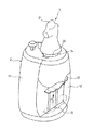
1 is a perspective view showing an overall configuration example of a directing toy for explaining an embodiment of the present invention.
The directional toy (1) has a body portion (2) and a first operating portion (3).
The body portion 2 is configured to be capable of outputting at least a directing by light emission, and in this embodiment, it is configured to be capable of outputting a directing by light emission and voice. And a
The main body portion 2 is formed in a shape in which a liquid container such as a perfume bottle or the like is formed on the whole body and has a
The
At least a part of the
The
A mounting
The
The protruding and retracting
The
The mounting
A pair of convex portions 25a and 25b of the
The second operating portion 15 is supported by the
2 shows a functional block of the main body 2. Fig.
The main body portion 2 of the directional toy 1 includes a
The storage unit 35 includes a storage medium such as a ROM (Read Only Memory) or a RAM (Random Access Memory), and stores a program executed by the
The
3 to 5 show the operation of the director toy 1.
The
Subsequently, as shown in Fig. 5, when the second operating portion 15 is pushed, the
By the above operation, whenever the second operation section 15 is operated, the liquid in the main body section 2 is gradually reduced, and the liquid can be discharged as if the liquid is eventually eliminated.
A plurality of kinds of
Hereinafter, the configuration of the first detecting section 32 for obtaining the identification code and the identification code of the
6 and 7 show the configuration of the first detection unit 32, and Fig. 8 shows the configuration of the identification code assigned to the
The first detecting section 32 is constituted by a plurality of switches provided in the mounting
The mounting
The
A
The
It is possible to provide the same number of
The blade portion 24 projecting sideways is provided at the tip of the protruding and recessed
The width W1a of the receiving
Figs. 9 and 10 show a method of obtaining the identification code of the
9A in which the
9 (B), the
Subsequently, as shown in Fig. 9C, only the
9 (D), the second switch 41 is pushed (ON) by the
By the above operation, the identification code of the
Then, as shown in Fig. 10 (A), the
The
10B, one convex portion 25a of the
10C, the convex portion 25a of the
11, the
Hereinafter, a mechanism for moving the
Figs. 12 and 13 are diagrams showing a configuration example of a mechanism for moving the
The moving
The
The
The swing arm 111 of the
The moving
The driving
The driving
The
Fig. 14 shows the operation of the moving
14A shows a state in which the
The driving
The rotation of the
When the
By repeating the above operation, the
When the
It should be understood that the embodiments disclosed herein are illustrative and non-restrictive in all respects. The scope of the present invention is not limited to the above description, and is intended to include all modifications within the meaning and scope equivalent to those of the appended claims.
1: Directed toys
2:
3:
10:
11: Case
12: cover
13:
14:
15:
30:
31:
Claims (15)
A movable portion movable in a predetermined space, a light emitting portion emitting light toward the movable portion, and a movable portion movable in a detachable manner with respect to a mounting portion provided on the main body portion, the movable portion movable in a predetermined direction 1 operation unit,
Wherein the movable portion is movable up to one of the movable stopping positions by mounting the first operating portion on the mounting portion.
And the sounding section emits a first sound every time the second operation section is operated.
Applications Claiming Priority (3)
| Application Number | Priority Date | Filing Date | Title |
|---|---|---|---|
| JPJP-P-2014-244081 | 2014-12-02 | ||
| JP2014244081A JP5802322B1 (en) | 2014-12-02 | 2014-12-02 | Production toy |
| PCT/JP2015/080333 WO2016088480A1 (en) | 2014-12-02 | 2015-10-28 | Bells-and-whistles toy |
Publications (2)
| Publication Number | Publication Date |
|---|---|
| KR20170063858A KR20170063858A (en) | 2017-06-08 |
| KR101931458B1 true KR101931458B1 (en) | 2018-12-20 |
Family
ID=54477757
Family Applications (1)
| Application Number | Title | Priority Date | Filing Date |
|---|---|---|---|
| KR1020177011501A KR101931458B1 (en) | 2014-12-02 | 2015-10-28 | Bells-and-whistles toy |
Country Status (5)
| Country | Link |
|---|---|
| JP (2) | JP5802322B1 (en) |
| KR (1) | KR101931458B1 (en) |
| CN (1) | CN105327515B (en) |
| HK (1) | HK1218092A1 (en) |
| WO (1) | WO2016088480A1 (en) |
Families Citing this family (13)
| Publication number | Priority date | Publication date | Assignee | Title |
|---|---|---|---|---|
| JP6480552B1 (en) * | 2017-12-01 | 2019-03-13 | 株式会社バンダイ | Production output toy and articles for production output toy |
| JP6990126B2 (en) * | 2018-03-12 | 2022-01-12 | 株式会社バンダイ | Luminous toys |
| JP6914893B2 (en) * | 2018-07-02 | 2021-08-04 | 株式会社バンダイ | Block toys |
| JP6626181B1 (en) * | 2018-11-13 | 2019-12-25 | 株式会社バンダイ | Production output toy, production output toy set, and operation tool for production output toy |
| JP7250861B2 (en) * | 2020-05-22 | 2023-04-03 | 株式会社バンダイ | directing output toy |
| JP6983291B1 (en) * | 2020-09-04 | 2021-12-17 | 株式会社バンダイ | Directing output toys |
| JP6964171B1 (en) * | 2020-10-09 | 2021-11-10 | 株式会社バンダイ | Directing output toys |
| JP7204722B2 (en) * | 2020-11-30 | 2023-01-16 | 株式会社バンダイ | Combined toy, control subject toy body and companion toy |
| JP6998443B1 (en) * | 2020-12-02 | 2022-01-18 | 株式会社バンダイ | Information retention medium and production output toys |
| JP7225186B2 (en) * | 2020-12-02 | 2023-02-20 | 株式会社バンダイ | directing output toy |
| CN113034879A (en) * | 2021-03-17 | 2021-06-25 | 南京嘉浩科技有限公司 | Remote control rotating device and remote control method |
| JP7102575B1 (en) * | 2021-04-14 | 2022-07-19 | 株式会社バンダイ | Directing output toys |
| JP7236504B2 (en) * | 2021-06-30 | 2023-03-09 | 株式会社バンダイ | Toy sets, containers and decorative toys |
Citations (4)
| Publication number | Priority date | Publication date | Assignee | Title |
|---|---|---|---|---|
| JP2004209226A (en) * | 2002-12-16 | 2004-07-29 | Masayoshi Suyama | Device for spinning top with reflecting mirror |
| JP2007029317A (en) * | 2005-07-26 | 2007-02-08 | Matsushita Electric Works Ltd | Luminous pattern-configuring toy |
| JP2007135935A (en) * | 2005-11-18 | 2007-06-07 | Birthday:Kk | Disassembling/assembling type toy doll |
| JP4287949B2 (en) | 1999-06-08 | 2009-07-01 | 有限会社 ワッツ | Candy holder |
Family Cites Families (7)
| Publication number | Priority date | Publication date | Assignee | Title |
|---|---|---|---|---|
| JPS5440136Y2 (en) * | 1976-10-15 | 1979-11-27 | ||
| JPS6420880A (en) * | 1987-07-16 | 1989-01-24 | Takara Co Ltd | Variable house toy |
| JP2007029316A (en) * | 2005-07-26 | 2007-02-08 | Matsushita Electric Works Ltd | Luminous pattern-configuring toy |
| US20070031808A1 (en) * | 2005-08-05 | 2007-02-08 | Kuo-Jui Wei | Protractile electric tombstone toy |
| JP4872019B1 (en) * | 2010-12-01 | 2012-02-08 | 株式会社バンダイ | Toy |
| JP4932953B1 (en) * | 2011-07-05 | 2012-05-16 | 株式会社バンダイ | Operational toy and movable member |
| JP4971520B1 (en) * | 2011-11-24 | 2012-07-11 | 株式会社バンダイ | Makeup toy and wearing body for makeup toy |
-
2014
- 2014-12-02 JP JP2014244081A patent/JP5802322B1/en active Active
-
2015
- 2015-08-28 JP JP2015169565A patent/JP6473676B2/en active Active
- 2015-10-28 KR KR1020177011501A patent/KR101931458B1/en active IP Right Grant
- 2015-10-28 WO PCT/JP2015/080333 patent/WO2016088480A1/en active Application Filing
- 2015-11-27 CN CN201510849592.9A patent/CN105327515B/en active Active
-
2016
- 2016-05-26 HK HK16106024.9A patent/HK1218092A1/en not_active IP Right Cessation
Patent Citations (4)
| Publication number | Priority date | Publication date | Assignee | Title |
|---|---|---|---|---|
| JP4287949B2 (en) | 1999-06-08 | 2009-07-01 | 有限会社 ワッツ | Candy holder |
| JP2004209226A (en) * | 2002-12-16 | 2004-07-29 | Masayoshi Suyama | Device for spinning top with reflecting mirror |
| JP2007029317A (en) * | 2005-07-26 | 2007-02-08 | Matsushita Electric Works Ltd | Luminous pattern-configuring toy |
| JP2007135935A (en) * | 2005-11-18 | 2007-06-07 | Birthday:Kk | Disassembling/assembling type toy doll |
Also Published As
| Publication number | Publication date |
|---|---|
| JP2016106678A (en) | 2016-06-20 |
| KR20170063858A (en) | 2017-06-08 |
| CN105327515A (en) | 2016-02-17 |
| WO2016088480A1 (en) | 2016-06-09 |
| JP5802322B1 (en) | 2015-10-28 |
| CN105327515B (en) | 2018-04-13 |
| HK1218092A1 (en) | 2017-02-03 |
| JP6473676B2 (en) | 2019-02-20 |
| JP2016107058A (en) | 2016-06-20 |
Similar Documents
| Publication | Publication Date | Title |
|---|---|---|
| KR101931458B1 (en) | Bells-and-whistles toy | |
| JP3150282U (en) | Push button device | |
| JP7059084B2 (en) | Directing output toys | |
| JP4770321B2 (en) | Game machine operation switch | |
| WO2017010187A1 (en) | Toy | |
| JP6396955B2 (en) | Game machine | |
| US9242183B2 (en) | Toy | |
| JP6196802B2 (en) | Game machine | |
| JP6084786B2 (en) | Electric machine lighting structure | |
| JP5421089B2 (en) | Button unit for gaming machines | |
| JP2007317380A (en) | Operation switch | |
| JP2014200515A (en) | Game machine | |
| JP6281066B2 (en) | Game machine | |
| CN114307195B (en) | Performance output toy | |
| JP7177206B2 (en) | toy | |
| JP6364345B2 (en) | Illuminated push switch for gaming machines | |
| JP2004349209A (en) | Switch device with luminescence display part | |
| JP6998443B1 (en) | Information retention medium and production output toys | |
| JP7224965B2 (en) | working toy | |
| JP6346681B2 (en) | Game machine | |
| JP6001927B2 (en) | Knock-type writing instrument | |
| JP2004062345A (en) | Mouse | |
| JP2005270274A (en) | Prize winning device for pachinko game machine | |
| JP2011210510A (en) | Led lighting system |
Legal Events
| Date | Code | Title | Description |
|---|---|---|---|
| A201 | Request for examination | ||
| E902 | Notification of reason for refusal | ||
| E701 | Decision to grant or registration of patent right |