JP7225186B2 - directing output toy - Google Patents
directing output toy Download PDFInfo
- Publication number
- JP7225186B2 JP7225186B2 JP2020200291A JP2020200291A JP7225186B2 JP 7225186 B2 JP7225186 B2 JP 7225186B2 JP 2020200291 A JP2020200291 A JP 2020200291A JP 2020200291 A JP2020200291 A JP 2020200291A JP 7225186 B2 JP7225186 B2 JP 7225186B2
- Authority
- JP
- Japan
- Prior art keywords
- toy
- toy body
- sub
- main
- output
- Prior art date
- Legal status (The legal status is an assumption and is not a legal conclusion. Google has not performed a legal analysis and makes no representation as to the accuracy of the status listed.)
- Active
Links
Images


Classifications
-
- A—HUMAN NECESSITIES
- A63—SPORTS; GAMES; AMUSEMENTS
- A63H—TOYS, e.g. TOPS, DOLLS, HOOPS OR BUILDING BLOCKS
- A63H33/00—Other toys
-
- A—HUMAN NECESSITIES
- A63—SPORTS; GAMES; AMUSEMENTS
- A63H—TOYS, e.g. TOPS, DOLLS, HOOPS OR BUILDING BLOCKS
- A63H33/00—Other toys
- A63H33/22—Optical, colour, or shadow toys
-
- A—HUMAN NECESSITIES
- A63—SPORTS; GAMES; AMUSEMENTS
- A63H—TOYS, e.g. TOPS, DOLLS, HOOPS OR BUILDING BLOCKS
- A63H33/00—Other toys
- A63H33/30—Imitations of miscellaneous apparatus not otherwise provided for, e.g. telephones, weighing-machines, cash-registers
-
- A—HUMAN NECESSITIES
- A63—SPORTS; GAMES; AMUSEMENTS
- A63H—TOYS, e.g. TOPS, DOLLS, HOOPS OR BUILDING BLOCKS
- A63H33/00—Other toys
- A63H33/42—Toy models or toy scenery not otherwise covered
-
- A—HUMAN NECESSITIES
- A63—SPORTS; GAMES; AMUSEMENTS
- A63H—TOYS, e.g. TOPS, DOLLS, HOOPS OR BUILDING BLOCKS
- A63H5/00—Musical or noise- producing devices for additional toy effects other than acoustical
-
- A—HUMAN NECESSITIES
- A63—SPORTS; GAMES; AMUSEMENTS
- A63J—DEVICES FOR THEATRES, CIRCUSES, OR THE LIKE; CONJURING APPLIANCES OR THE LIKE
- A63J7/00—Auxiliary apparatus for artistes
Description
本発明は、演出出力玩具に関する。 The present invention relates to a production output toy.
従来、演出出力玩具には所定の操作に基づいて音等を発生するものが知られている。この演出出力玩具においては、例えば、特許文献1においては、音声発生手段および発光手段と、これらの音声発生手段および発光手段を作動させる2種類のスイッチと、玩具本体に着脱可能な指輪を模した装飾品と、を有する。2種類のうち一方のスイッチは、使用者の手によって直接操作され、他方のスイッチは、装飾品の着脱によってオン・オフされる、コンパクト玩具が開示されている。このコンパクト玩具によれば、使用者は、一方のスイッチを直接操作することに加え、装飾品の着脱により他方のスイッチを操作することでも、音声発生手段および発光手段を作動させることができる。
2. Description of the Related Art Conventionally, there is known a production output toy that generates a sound or the like based on a predetermined operation. In this production output toy, for example, in
特許文献1においては、複数種の演出が得られるものの、演出の種類は、玩具本体に設けられるスイッチの個数に応じた程度にとどまり、また、演出を行う手段についても、単に電球と発音器を玩具本体に設けただけの構成である。近年、面白い玩具が求められる中、特許文献1のような構成では面白味に欠ける。
In
本発明は、興趣性の高い演出出力玩具を提供することを目的とする。 An object of the present invention is to provide a highly entertaining production output toy.
本発明に係る演出出力玩具は、第一主玩具体と、前記第一主玩具体に対して開閉可能な第二主玩具体と、を有する主玩具体と、前記第一主玩具体に設けられた、副玩具体が装着される副玩具体装着部と、演出出力部と、を備え、前記副玩具体は、前記副玩具体装着部に装着された状態にて回転可能に構成され、前記第二主玩具体は、前記副玩具体装着部に装着された前記副玩具体の回転位置の変化により、閉状態から開状態に変化可能に構成される。また本発明に係る演出出力玩具は、第一主玩具体と、前記第一主玩具体に対して開閉可能な第二主玩具体と、を有する主玩具体と、前記第一主玩具体に設けられた、副玩具体が装着される副玩具体装着部と、演出出力部と、を備え、前記副玩具体は、ベース部と、前記ベース部の一端側に設けられ前記副玩具体装着部に挿入される挿入部と、前記挿入部と前記ベース部を挟んで反対側に前記ベース部に対して回動可能に支持された回転操作部と、を含み、前記副玩具体の前記回転操作部は、前記副玩具体装着部に装着された状態にて回転可能に構成され、前記第二主玩具体は、前記副玩具体装着部に装着された前記回転操作部の回転位置の変化により、閉状態から開状態に変化可能に構成される。また本発明に係る演出出力玩具は、第一主玩具体と、前記第一主玩具体に対して開閉可能な第二主玩具体と、を有する主玩具体と、前記第一主玩具体に設けられた、副玩具体が装着される副玩具体装着部と、演出出力部と、を備え、前記副玩具体には、前記演出出力部にて演出を可能にする前記副玩具体に特有な識別突起が設けられ、前記主玩具体には、前記識別突起を検出する検出部が設けられ、前記副玩具体の少なくとも一部は、前記副玩具体装着部に装着された状態にて回転可能に構成され、前記第二主玩具体は、前記副玩具体装着部に装着された前記副玩具体の少なくとも一部の回転位置の変化により、閉状態から開状態に変化可能に構成される。 A presentation output toy according to the present invention comprises: a main toy body having a first main toy body; a sub-toy body attachment part to which the sub-toy body is attached; and a presentation output part, wherein the sub-toy body is configured to be rotatable in a state of being attached to the sub-toy body attachment part, The second main toy body can be changed from a closed state to an open state by changing the rotational position of the secondary toy body attached to the secondary toy body attachment portion. A presentation output toy according to the present invention includes a main toy body having a first main toy body and a second main toy body that can be opened and closed with respect to the first main toy body, and the first main toy body. A sub-toy body mounting portion to which a sub-toy body is mounted, and a performance output portion provided, wherein the sub-toy body is provided on a base portion and one end side of the base portion to mount the sub-toy body. and a rotation operation part rotatably supported with respect to the base part on the opposite side of the insertion part and the base part, and the rotation of the sub toy body. The operation part is configured to be rotatable while attached to the sub-toy body mounting part, and the second main toy body is adapted to change the rotational position of the rotation operation part attached to the sub-toy body mounting part. , so that it can be changed from the closed state to the open state. A presentation output toy according to the present invention includes a main toy body having a first main toy body and a second main toy body that can be opened and closed with respect to the first main toy body, and the first main toy body. A sub-toy body attachment section to which a sub-toy body is attached, and a presentation output section are provided, and the sub-toy body includes a sub-toy body specific to the sub-toy body that enables presentation at the presentation output section. an identifying projection is provided, the main toy body is provided with a detecting portion for detecting the identifying projection, and at least a part of the sub-toy body rotates while being mounted on the sub-toy body mounting portion. The second main toy body is configured to be able to change from a closed state to an open state by changing the rotational position of at least a part of the secondary toy body mounted on the secondary toy body mounting portion. .
また、本発明に係る演出出力玩具においては、前記副玩具体は、ベース部と、前記ベース部の一端側に設けられ前記副玩具体装着部に挿入される挿入部と、前記挿入部と前記ベース部を挟んで反対側に前記ベース部に対して回動可能に支持された回転操作部と、を含む、ようにしてもよい。 Further, in the presentation output toy according to the present invention, the sub-toy body includes a base portion, an insertion portion provided on one end side of the base portion and inserted into the sub-toy body mounting portion, the insertion portion and the and a rotation operating portion supported rotatably with respect to the base portion on the opposite side of the base portion.
また、本発明に係る演出出力玩具においては、前記回転操作部には、その回転径方向において最大径の最大突起が設けられ、前記回転操作部の回転により、前記最大突起の先端部が前記第二主玩具体(蓋部材)の前記閉状態の係止部を押上げて前記開状態にする、ようにしてもよい。 Further, in the production output toy according to the present invention, the rotation operating portion is provided with a maximum projection having a maximum diameter in the radial direction of rotation thereof, and rotation of the rotation operation portion causes the tip portion of the maximum projection to move to the above-mentioned position. The locking portion of the second main toy body (lid member) in the closed state may be pushed up to the open state.
また、本発明に係る演出出力玩具においては、前記副玩具体が前記副玩具体装着部に装着された状態において、前記第二主玩具体が前記開状態から前記閉状態に回転されるときに、前記係止部が前記最大突起の先端部の前記副玩具体装着部側の縁部に当接可能な傾斜構造を備えている、ようにしてもよい。 Further, in the presentation output toy according to the present invention, when the second main toy body is rotated from the open state to the closed state in the state where the sub toy body is mounted on the sub toy body mounting portion. Alternatively, the engaging portion may have an inclined structure capable of coming into contact with the edge portion of the tip portion of the largest projection on the side of the auxiliary toy body mounting portion.
また、本発明に係る演出出力玩具においては、前記挿入部は、形状の異なる部分が設けられ、前記副玩具体装着部には、前記挿入部に対応する形状の装着孔が設けられている、ようにしてもよい。 Further, in the production output toy according to the present invention, the insertion portion is provided with a portion having a different shape, and the sub-toy body mounting portion is provided with a mounting hole having a shape corresponding to the insertion portion. You may do so.
また、本発明に係る演出出力玩具においては、前記ベース部と前記副玩具体装着部と間には、前記副玩具体を装着したときに、斜め装着を防止する斜め装着防止機構が設けられている、ようにしてもよい。 In addition, in the presentation output toy according to the present invention, an oblique attachment prevention mechanism is provided between the base portion and the sub toy attachment portion to prevent oblique attachment when the sub toy is attached. Yes, you can.
また、本発明に係る演出出力玩具においては、前記回転操作部の回転位置を規制するストッパ機構が設けられている、ようにしてもよい。 Further, the effect output toy according to the present invention may be provided with a stopper mechanism for restricting the rotational position of the rotational operation portion.
また、本発明に係る演出出力玩具においては、前記回転操作部は、その回転径方向において最大径の最大突起が設けられ、前記回転操作部には、前記最大突起とは別に回転径方向に突出する突起部が設けられている、ようにしてもよい。 Further, in the presentation output toy according to the present invention, the rotation operation part is provided with a maximum projection having a maximum diameter in the rotation radial direction, and the rotation operation part protrudes in the rotation radial direction separately from the maximum projection. A protrusion may be provided to
また、本発明に係る演出出力玩具においては、前記突起部は、前記最大突起の先端部が接触する前記第二主玩具体の部分とは非接触となるように突出している、ようにしてもよい。 Further, in the production output toy according to the present invention, the protrusion protrudes so as not to contact the second main toy body portion with which the tip of the largest protrusion contacts. good.
また、本発明に係る演出出力玩具においては、前記突起部は、前記最大突起の先端部に対して前記副玩具体装着部から離れる方向にオフセットされている、ようにしてもよい。 Further, in the presentation output toy according to the present invention, the protrusion may be offset from the tip of the maximum protrusion in a direction away from the sub-toy body mounting section.
また、本発明に係る演出出力玩具においては、前記副玩具体装着部は、前記副玩具体の外周端面の位置より外側に平坦な領域が設けられている、ようにしてもよい。 Further, in the presentation output toy according to the present invention, the sub-toy body mounting portion may be provided with a flat area outside the position of the outer peripheral end face of the sub-toy body.
また、本発明に係る演出出力玩具においては、前記第二主玩具体の回転支軸の軸回りには、前記第二主玩具体の少なくとも開状態を維持可能な仮係止機構が設けられている、ようにしてもよい。 In addition, in the presentation output toy according to the present invention, a temporary locking mechanism capable of maintaining at least the open state of the second main toy body is provided around the axis of the rotation support shaft of the second main toy body. Yes, you can.
また、本発明に係る演出出力玩具においては、前記副玩具体には、前記演出出力部にて演出を可能にする前記副玩具体に特有な識別突起が設けられ、前記主玩具体には、前記識別突起を検出する検出部が設けられている、ようにしてもよい。 Further, in the effect output toy according to the present invention, the sub toy body is provided with an identification projection peculiar to the sub toy body that enables the effect in the effect output section, and the main toy body is provided with: A detection unit for detecting the identification protrusion may be provided.
また、本発明に係る演出出力玩具においては、前記識別突起は、その突出高さが周辺の突出壁部と同等かそれよりも低く構成されている、ようにしてもよい。 Further, in the presentation output toy according to the present invention, the identification projection may be configured such that the projection height thereof is equal to or lower than that of the surrounding projection wall portion.
また、本発明に係る演出出力玩具においては、前記副玩具体の識別突起は、前記主玩具体の検出部の数よりも多く設けられている、ようにしてもよい。 Also, in the presentation output toy according to the present invention, the identification projections of the sub-toy body may be provided in a number greater than the number of detecting portions of the main toy body.
また、本発明に係る演出出力玩具においては、前記副玩具体とは別に、第2の副玩具体を含み、前記第2の副玩具体は、前記主玩具体の演出と連動する演出が可能である、ようにしてもよい。 In addition, the presentation output toy according to the present invention includes a second sub-toy body separately from the sub-toy body, and the second sub-toy body is capable of performing a presentation interlocking with the presentation of the main toy body. , you may do so.
本発明によれば、興趣性の高い演出出力玩具を提供することができる。 According to the present invention, it is possible to provide a highly entertaining production output toy.
以下、本発明の一実施形態の演出出力玩具について、図1~図16を参照して説明する。 A presentation output toy according to an embodiment of the present invention will be described below with reference to FIGS. 1 to 16. FIG.
図1に示す演出出力玩具1は、本発明の化粧玩具の一例であり、例えばテレビ番組等の主人公の、戦う女戦士のヒロインが携帯している化粧用コンパクトの形状を模った玩具である。このヒロインは、番組上、化粧用コンパクトに様々な装着体を装着することで、化粧用コンパクトや指輪、化粧用ハケ等を用いて、化粧用コンパクトから音や光を出したり、変身したりする設定となっている。ここで、「変身」とは、ヒロインの化粧や髪型、衣服、靴、アクセサリー等が変化することを言う。使用者は、この化粧玩具により、当該ヒロインになりきる、いわゆる「なりきり遊び」をすることが可能な玩具である。
The
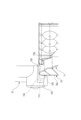
図1は、演出出力玩具1の全体を示す斜視図である。
図1に示すように、演出出力玩具1(以下、単に「玩具」という)は、大別すると、携帯型の化粧料容器(いわゆるコンパクト)を模して形成される主玩具体10と、主玩具体10に対して着脱自在に構成され、指に嵌めることができる指輪を模した副玩具体20(以下、単に「指輪部材」という)と、化粧用のハケを模した第2の副玩具体(後述のブラシ部材30(図13参照))と、を有する。主玩具体10は、その前面に指輪部材20が装着される副玩具体装着部15(以下、単に「装着部」という)を備える第一主玩具体である円筒形の本体部11と、本体部11に対して開閉可能な第二主玩具体であるお椀型球欠形状の蓋部12とを備える。なお、本体部11内には演出出力部である音出力部70や光出力部80(図2参照)が設けられており、後述する操作に基づいて、光や音による所定の演出を行うことができる。
FIG. 1 is a perspective view showing the whole
As shown in FIG. 1, the effect output toy 1 (hereinafter simply referred to as "toy") can be roughly divided into a
ここで、指輪部材20は、色や形、模様等の異なる複数のもの(その一例のみ図示)が用意されており、それぞれが異なる後述する識別情報を有する。したがって、指輪部材20を装着部15に装着することで、指輪部材20に応じた所望の演出を行うことができる。
Here, a plurality of
図2は、図1に示す演出出力玩具の蓋部が開いた状態の斜視図である。
玩具1は、その使用に際しては、後述する蓋部12を開く操作、並びに蓋部12を開いた状態で使用する。図2に示すように、本体部11の上面中央には、演出操作を行う比較的大きいメインのトリガーボタン11aやサブボタン11bが上面に設けられている。また、電源スイッチ11s(図16参照)は、例えば本体部11の裏側に設けられている。蓋部12には、その内側に、円形の鏡12mが設けられている。トリガーボタン11aは、本体部11の上端面から若干盛り上がった形状に構成されており、また、素材としては、透明若しくは半透明の光透過性の素材にて構成されている。例えば、トリガーボタン11aの内側には、LED等の発光部材等からなる光出力部80が配置されている。したがって、光出力部80の発光によって、トリガーボタン11a又はその周囲が光る。音出力部70についても適所に配置されている。
FIG. 2 is a perspective view of the effect output toy shown in FIG. 1 with the lid portion opened.
When using the
蓋部12は、ヒンジ部18を介して本体部11に対して開閉自在に構成されている。この蓋部12は、少なくとも一部が光透過性の部材にて構成されている。蓋部12の閉じ状態は、ヒンジ部18とは反対側の先端に設けられた係止部12tにより維持される。この蓋部12の開き操作は、図2に示すように、装着部15に装着された指輪部材20の、後述する回転交差により、閉状態から開状態に変化する。
The
図3は、蓋部の閉じ状態における係止構造を示す拡大側面図である。
図3に示すように、係止部12tは、蓋部12の外周縁12gよりも円周方向外側(図中左側)に突出すると共に本体部11側にも突出している。要するに、係止部12tは、装着部15の平坦面15eに対面するように張り出している。そして、平坦面15eに向かって開口する係合凹部12cを備えている。一方、平坦面15eの上端には、本体部11の径方向外側に向かって突出する蓋係止突起11tが設けられている。したがって、蓋部12の閉じ状態においては、蓋係止突起11tと係合凹部12cとが係合しており、蓋部12の閉じ状態が維持される。
いる。
FIG. 3 is an enlarged side view showing the locking structure in the closed state of the lid.
As shown in FIG. 3, the engaging
there is
図4は、指輪部材20を側面側から見た斜視図である。
図4に示すように、指輪部材20は、略円盤状のベース部21を中央にして、ベース部21の厚み方向の一端側(図中右側)には挿入突起部22が設けられ、挿入突起部22とはベース部21を挟んで反対側には、回転操作部23が設けられている。挿入突起部22は、装着部15の装着孔15c(図1参照)に挿入される部分であり、ベース部21に固定して設けられている。回転操作部23は、ベース部21に対して回転軸線CLを中心に回動可能に設けられている。
FIG. 4 is a perspective view of the
As shown in FIG. 4, the
挿入突起部22は、回転軸線CL方向に沿って第1突起部22a及び第2突起部22bが延出されている。第1突起部22a及び第2突起部22bは、指に嵌めることができる湾曲形状に構成されている。また、第1突起部22aと第2突起部22bとは、その形状が少し異なっている。例えば、第2突起部22bの幅(D2)は、第1突起部22aの幅(D1)よりも小さく構成されている。
The
回転操作部23は、略円盤状の形状に構成されており、その表面側には例えばヒロインのキャラクターに対応する部柄や配色が施されている。例えば、回転操作部23の外周縁部分には、装飾の一部として凹凸形状が適宜設けられている。そして、その凹凸形状の内の1つが、回転軸線CLからの距離が最大径(D3)の最大突起23bが設けられている。また、回転操作部23には、最大突起23bとは別に回転径方向に突出する複数の張出部23c(図5参照)が設けられている。張出部23cの先端部分の回転軸線CLからの距離(D4)は、最大突起23bよりも若干小さく構成されている。
The
張出部23cは、最大突起23bとは、回転軸線CLの方向においてその突出位置が所定寸法(h)ずれている。すなわち、張出部23cの突出位置は、最大突起23bに対して装着部15から離れる方向にオフセットされている。これにより指先が掛けやすい。また、最大突起23bの先端部23eが当る係止部12tとは非接触となるように構成されている。
The protruding
図5は、指輪部材20を裏面側から見た斜視図である。図6は、挿入突起部22を取り外した状態の指輪部材20を裏面側から見た斜視図である。
図5及び図6に示すように、指輪部材20のベース部21の裏面側には、複数の略円柱状の識別突起21pが挿入突起部22の両側に並んで突設されている。また、識別突起21pに接近した位置には、識別突起21pが並んだ方向に略沿うと共に若干外側に湾曲するように突出壁部21wが設けられている。この突出壁部21wには、その外側面に内側へ凹む係止凹部21iが設けられている。この突出壁部21wにおいては、例えば、図中の右側のものは、その両端側が識別突起21pとしても構成されている。また、突出壁部21wの間には、挿入突起部22を挟む位置に他の突出壁部21rが設けられている。
FIG. 5 is a perspective view of the
As shown in FIGS. 5 and 6 , a plurality of substantially
また、識別突起21pは、その突出高さ(H1)が周囲の突出部位と同等かそれよりも低い構成が望ましい。例えば、本実施形態においては、図示の如く、周辺の突出壁部21wと同じに構成されている。また、他の突出壁部21rのうち一方(図7において左側)のものは、識別突起21pの高さ(H1)よりも高い高さ(H2)となっている。
In addition, it is desirable that the
図7は、本体部11の装着部15を示す拡大斜視図である。
図7に示すように、装着部15は、本体部11の外周面から径方向外側に若干突出した突出部の中に略円形の円形凹部15aが形成され、その円形凹部15a内に装着孔15cを備える。また、装着部15の突出上端面は略平坦な平坦面15eとして構成されている。この平坦面15eは、指輪部材20が装着されたときに、指輪部材20の大きさ(指輪部材の径方向の大きさ)に対して十分な大きさを有するように構成されている。要するに、指輪部材20を回転操作するときに支障がないように構成されている。
円形凹部15aの底面部には、指輪部材20が装着されたときに、識別突起21pを検出する出没ピン型の検出部14pが装着孔15cの両側に複数設けられている。検出部14pは、例えば、識別突起21pによって押されることでスイッチングが行われる。そして、検出部14pの検出信号は、制御部60に送信される。検出部14pの周囲には、識別突起21pを検出部14pに案内するガイド壁部15gが設けられている。
FIG. 7 is an enlarged perspective view showing the mounting
As shown in FIG. 7, the mounting
On the bottom surface of the
ここで、検出部14pの数は、本実施啓太においては5個である。一方、指輪部材20の識別突起21pは、図5に示したように、例えば、8個設けられている。これは、この指輪部材20は、本体部11以外のものにも対応可能な識別突起21pを有していることになる。
Here, the number of
また、円形凹部15aの内周壁面には、指輪部材20の突出壁部21wと接触して突出壁部を案内する突出内周壁15wが、図中において左右に2個ずつ4箇所に設けられている。この突出内周壁15wは、指輪部材20の突出壁部21wに対応して設けられている。また、突出内周壁15wに隣接した位置には、ばね部材(不図示)によって円形凹部15a中央側に付勢された係止フック15fが設けられている。この係止フック15fは、指輪部材20の突出壁部21wに設けられた係止凹部21iに係合する。要するに、指輪部材20が装着されたときに、突出内周壁15wと突出壁部21wとの係合並びに係止フック15fと係止凹部21iとの嵌合が行われる。この係合及び嵌合は、指輪部材20の斜め装着を防止する斜め装着防止機構として機能する。
In addition, on the inner peripheral wall surface of the
また、装着孔15cの形状は、一端側が円形に形成され、他端側が矩形に形成された鍵穴形状となっている。そして、指輪部材20の挿入突起部22は、例えば円形の側に幅広の第1突起部22aが挿入されることで、挿入時の上下位置が規制される。なお、挿入突起部22を挟む位置に設けられた一対の突出壁部21rは、装着孔15c内に進入するように構成されており、この一対の突出壁部21rの幅を装着孔15cの形状や幅に合わせたサイズに構成することによっても、向きの誤挿入を回避できるようにしても良い。
Further, the shape of the mounting
図8は、指輪部材20の分解斜視図である。
図8に示すように、回転操作部23の裏面側は、例えば、有底筒状の凹部に構成されており、回転軸線CLに沿って回転軸部23fが設けられている。回転軸部23fは、ベース部21の支持孔21hに挿入されると共に当該支持孔21hから抜けないように取り付けられる(抜け止構造は不図示)ことで、ベース部21に回動可能に支持される。なお、回転操作部23の裏面側の円弧状の突壁23weは、ベース部21の円形の段部21eに係合されて、回転操作部23の回転動を円滑にする。
FIG. 8 is an exploded perspective view of the
As shown in FIG. 8, the rear side of the
回転操作部23は、その回転位置を規制するストッパ機構55が設けられている。ストッパ機構55は、ストッパピン55b,55dと位置規制壁55a,55cとで構成されている。ストッパピン55b,55dは、回転操作部23において回転軸部23fと平行に突設されている。一方、位置規制壁55a,55cは、ベース部21のベース面21mに設けられている。このストッパ機構55は、回転操作部23を回転操作するときに、回動操作前の初期位置から回転操作終了位置(蓋部開動位置)までの回転角度にして略90度で停止させる。例えば、初期位置から蓋部開動位置へ移動したときは、ストッパピン55dが位置規制壁55cに当って回転が停止される。また、初期位置に戻すときは、ストッパピン55bが位置規制壁55aに当って回転が停止される。
The
図9は、指輪部材20の装着初期の状態を示す拡大正面斜視図である。図10は、指輪部材20の装着初期の状態を示す拡大側面図である。
図9に示すように、装着部15に指輪部材20を装着する。この当初の装着状態においては、回転操作部23は、最大突起23bが横の位置(図9において左横向の状態)で装着する。この装着初期の状態では、張出部23cの1つが係止部12tと前後方向で重なる位置となっている。しかし、図10に示すように、側面方向から見ると、上側に位置する張出部23cは、係止部12tの外側に位置しており、係止部12tには接触することがない。また、指輪部材20は、装着部15の平坦面15eから回転操作部23が離れた状態で装着されており、回転操作がし易い状態で装着されている。
FIG. 9 is an enlarged front perspective view showing the initial state of wearing the
As shown in FIG. 9, the
また、下側に位置する張出部23cは、平坦面15eの下端縁15dよりも内側(図9において上側)に位置しており、本体部11の下に突出したり載置面に接したりすることはない。このように、装着部15の平坦面15eは、指輪部材20の外周端の位置より外側に広がる平坦な領域として形成されており、回転操作部23の操作がし易い構成となっている。
Further, the projecting
図11は、指輪部材20の回転操作が完了した状態を示す拡大正面図である。
次に、図11に示すように、指輪部材20の装着初期状態から、回転操作部23を時計回りの方向に90度回転する。この回転によって、指輪部材20の最大突起23bは、蓋部12の係止部12tに当接して蓋部12を開く方向に押上げる。この回動完了状態において、下側に位置する張出部23cについても、平坦面15eの下端縁15dの内側に位置している。
FIG. 11 is an enlarged front view showing a state where the rotation operation of the
Next, as shown in FIG. 11, from the initial wearing state of the
回転操作部23によって蓋部12が開かれるときの動作について説明する。
図12は、蓋部12を開けるときの動作を示す拡大側面図である。
図12に示すように、蓋部12の閉じ状態では、係止部12tの係合凹部12cが蓋係止突起11tに係合した状態(図3参照)であるが、指輪部材20の回転操作終段において、最大突起23bの突起側面23bs(図11参照)が係止部12tの係止部下端面12tsに当接し始める。この係止部下端面12tsに対する突起側面23bsの当接は、回転が進むにしたがって強くなり、係止部12tを無理やり押上げる。これによって、係合凹部12cの凹部傾斜面12sと蓋係止突起11tの傾斜面11tsに案内されるようにして、蓋係止突起11tの係止状態が外れる。この結果、蓋部12は、最大突起23bに押上げられて係止状態が解除される。
The operation when the
FIG. 12 is an enlarged side view showing the operation of opening the
As shown in FIG. 12, when the
図13は、ヒンジ部18の構造を示す要部の拡大断面図である。
図13に示すように、蓋部12は、その係止状態が解除されヒンジ部18を中心にして開くことができる。ヒンジ部18は、回動軸部18aが回転支軸18bにて貫通されて回動可能に支持されている。回動軸部18aには、外周面に平坦部18dが軸回り円周方向に間隔を開けて2つ設けられている。さらに、平坦部18dには、外面凹部18cが設けられている。一方、本体部11には、平坦部18d及び外面凹部18cに対応する平坦部及び係止凸11gを有する押圧部11iが設けられている。押圧部11iは、押圧ばね11spにより回転支軸18bに向かって押圧されている。したがって、係止凸11gが外面凹部18cに嵌まり込むことにより、蓋部12の仮係止が可能である仮係止機構を備える。この押圧部11iは、回動軸部18aの外面に形成された平坦部に対面することで、回転時のクリック感を出すことができる。
FIG. 13 is an enlarged cross-sectional view of a main portion showing the structure of the
As shown in FIG. 13, the
係止凸11gによる蓋部12の係止は、蓋部12が閉じた状態と開かれた状態(図示の状態)とで行われる。例えば、蓋部12の閉じ状態から開かれるときは、回動軸部18aの回転によって、当初の平坦部18dが押圧部11iからずれるように回動する。これによって、平坦部18dの隣の第2平坦部18eが押圧部11iによって支持される位置に一端停止される、所謂クリック動作が行われる。このクリック動作は、前掲の指輪部材20による蓋部12の係止状態の解除のときに行われる。最終的に蓋部12が完全に開かれた状態(図示の状態)では、外面凹部18cが係止凸11gに嵌って係止される。
The engagement of the
図14は、蓋部12が閉じるときの要部を拡大した側面図である。
通常の操作を終了する場合には、本体部11から指輪部材20を外して蓋部12を閉じる操作を行う。しかし、指輪部材20が本体部11に装着された状態のまま蓋部12を閉じることも想定される。この場合について、以下説明する。
FIG. 14 is an enlarged side view of the main part when the
When finishing the normal operation, the
指輪部材20を装着部15に装着したままの状態で蓋部12を閉じると、図14に示すように、蓋部12の係止部12tが指輪部材20の最大突起23bに当接する状態が生じる。このとき、係止部12tは、最大突起23bの先端部23eの本体部11側の縁部23ekに斜めに当接する。また、縁部23ekは、適宜大きさのR面に形成されている。これにより、係止部12tが縁部23ekに当ったときに、係止部下端面12tsは、縁部23ekを下方及び装着部15から離れる方向(図中左側)に向かう斜め下方に押すことになる。要するに、縁部23ekに加えられる力は、係止部下端面12tsと縁部23ekとの斜めの当接によって、図示の如く、斜め左下方(F1)に向かって押されることになる。要するに、斜め下方に向かって押される力(F1)の水平分力が、指輪部材20を装着部15から外す方向の力として働く。この結果、指輪部材20は外れ、且つ外れた直後の係止部12tは、その内側の係合凹部12cが蓋係止突起11tに引っ掛かって係止される(図3参照)。
When the
ここで、前掲の当接によって指輪部材20を外す力を生じさせるためには、本実施形態の如く、縁部23ekに対して、所定の傾きを持って当接すればよいが、この傾き角度並びにR面の大きさや角度を適宜設定することで、指輪部材20の外れ方を調整することができる。
Here, in order to generate a force to remove the
図15は、ブラシ部材30を示す斜視図である。
図15に示すように、ブラシ部材30は、化粧用のブラシを模した形状であり、外観的には、先端側のブラシ部31と把持部32とを有する。また、ブラシ部材30は、蓋部12の内側に設置された一対のブラシ取付部12gt間に嵌めるようにして収容することができる。なりきり遊びを行うときには、ブラシ部31を使用して、本体部11のトリガーボタン11a等を押す操作等を行うなど本体部11の演出と連動する演出が可能である。なお、ブラシ部材30は、それ自体に、電源、制御部、演出出力部、通信部、スイッチ等を備えていてもよい。例えば、主玩具体10に設けられた通信部と赤外線等で無線通信を行い、ブラシ部材30から、主玩具体10に装着された副玩具体の種類に応じた演出(音声や発光等)が出力されるようにしても良い。また、ブラシ部31のスイッチをオンすることにより、ブラシ部31から演出が出力されるようにしても良い。また、ブラシ部31が、光演出部として構成されている場合には、光る操作部材として遊び方の幅を広げることができる。
15 is a perspective view showing the
As shown in FIG. 15, the
図16は、玩具1の制御系を示すブロック図である。
図16に示すように、本体部11の内部には、制御部60が設けられている。制御部60と電池(不図示)とは、電源スイッチ11s(例えば本体部の裏側等に設けられている)を介して接続されている。これにより、電源スイッチ11sをオンにすると、制御部60に電流が流れて制御が開始される。制御部60は、検出部14p、メインのトリガーボタン11a、サブボタン11b、通信部11c等が接続される。また、制御部60には、記憶部61が接続されており、予め、指輪部材20の各々の識別情報に対する演出が設定されている。検出部14pで検知した指輪部材20の識別情報は、制御部60に送られる。この識別情報に基づいて、制御部60は、駆動部62を介し演出出力部である光出力部80及び音出力部70によって所定の演出を行う。なお、演出は、例えば、トリガーボタン11aが押圧されたときに、識別情報に基づいた所定の演出がなされるが、その他に、サブボタン11bを操作したときには、例えば、モード選択を行って異なる演出を発現する。また、制御部60は、指輪部材20が取り外されたときは、演出出力部による演出を停止する。
FIG. 16 is a block diagram showing the control system of the
As shown in FIG. 16 , a
以下、玩具1の遊び方の一例について説明する。
玩具1で遊ぶときは、先ず、電源スイッチ11sをオンにする。これにより起動音が演出される。その後、本体部11の装着部15に指輪部材20を装着する。この装着によって、装着音と共に本体部11の内部が発光する。その後、指輪部材20の回転操作部23を回転させて蓋部12を開ける。この蓋部12の開く動作に加えて、回転操作のひねり音も出力され、指輪部材20の特有キャラクターの台詞等がスタートする。その後、待機音がスタートし、次の操作を待つ。その後、例えば、メイク用のブラシ部材30を使用して、メイクの各種のバージョンの演出を行い、さらには、ドレスアップ演出、名乗り演出などを行い、変身の変化を楽しむ変身演出を行って楽しむことができる。以上の変身演出は、各指輪部材20の違いによって異なる演出となる。
An example of how to play the
When playing with the
以上述べたように、本実施形態の玩具1によれば、指輪部材20の装着と回動により蓋部12を開状態にできるので、演出出力に蓋部12の動きを付加した演出が可能になる。
As described above, according to the
また、本実施形態の玩具1によれば、指輪部材20は、挿入突起部22によって装着部15に確り保持され、回転操作部23がベース部21に保持されて回転するので、正確に回転することができ、蓋部12を確実に開状態にできる。
Further, according to the
また、本実施形態の玩具1では、回転操作部23の回転位置の変化により、最大突起23bの先端部23eが蓋部12の係止部12tを押上げて開状態にするので、係止部12tの係合解除のための複雑な構造を必要とせず、構造を簡素化できる。
In addition, in the
本実施形態の玩具1では、蓋部12が開状態から閉じ状態に回転されるときに、蓋部12の係止部12tが指輪部材20の縁部23ekに斜めに当接可能な構造を備えていることで、係止部12tが指輪部材20を装着状態から外す方向に押すことができる。この結果、指輪部材20を装着したままで蓋部12を閉じることがでる。また、縁部23ekに対する斜めに当接によって、指輪部材20の破損を回避することができる。
The
また、本実施形態の玩具1では、指輪部材20の挿入突起部22は、形状の異なる部分が設けられ、装着部15には、挿入突起部22に対応する形状の装着孔15cが設けられているので、指輪部材20の装着向きを正確にできる。
In addition, in the
本実施形態の玩具1では、指輪部材20のベース部21と装着部15と間には、指輪部材20を装着したときに、斜め装着を防止する斜め装着防止機構が設けられているので、識別突起21pの検出を正確にすることができる。また、指輪部材20の回転操作の回転軌跡が安定し、蓋部12の閉状態の解除動作が正確にできる。
In the
本実施形態の玩具1では、指輪部材20の回転操作部23の回転位置を規制するストッパ機構55が設けられているので、回転操作部23の廻りすぎを規制し、回転操作を安定したものにできる。
Since the
また、本実施形態の玩具1では、回転操作部23には、最大突起23bとは別に回転径方向に突出する張出部23cが設けられているので、回転操作部23の回転操作を行うときに、指先を掛ける箇所ができ回転操作がし易い。
In addition, in the
また、本実施形態の玩具1では、張出部23cは、蓋部12の係止部12tとは接触しないことから、回転操作部23の廻しやすさの向上と共に最大突起23bのみをロック解除の部分とすることができる。
In addition, in the
また、本実施形態の玩具1では、張出部23c、少なくとも最大突起23bに対して装着部15から離れる方向にオフセットされているので、張出部23cの張出しサイズを最大突起と同じにしても、蓋部12の一端とは係合することがなく、また、指を掛けやすい構造にできる。
In addition, in the
本実施形態の玩具1では、装着部15は、指輪部材20の最外径の部分よりも外側に平坦な領域が設けられていることで、指輪部材20を回転操作するときに回転操作をし易くすることができる。
In the
本実施形態の玩具1では、ヒンジ部18周りに仮係止機構が設けられているので、蓋部12を回動途中で仮止めすることができ、蓋部12の開き方を楽しむことができる。また、回動の途中においてクリック感をだすことができ、蓋部12の回動操作感を高めることができる。
In the
本実施形態の玩具1では、指輪部材20は装着部15に取り付けられたときに、検出部14pによって識別突起21pが検出されるので、識別突起21pの情報機能によって所定の演出を出力することができる。
In the
また、本実施形態の玩具1では、識別突起21pは、その突出高さが周辺の突出壁部21wと同等かそれよりも低く構成されているので、識別突起21pの保護ができる。
In addition, in the
また、本実施形態の玩具1では、識別突起21pが本体部11の検出部14pの数よりも多く設けられていることで、指輪部材20はより多くの識別パターンを有することができ、別の演出出力玩具に使用することが可能になる。
In addition, in the
また、本実施形態の玩具1では、ブラシ部材30は、それを使用して本体部11の操作ができるので、遊び方の幅を広げることができる。また、本体部11側の演出と連動する演出が可能であるので、演出出力の多様化を図ることができる。
In addition, in the
以上、本発明の一実施形態について説明したが、本発明はその技術思想の範囲で適宜変更することができる。例えば、本体部11や蓋部12,更には指輪部材20等の形状や構造においては、図示のものに何ら制限されるものではなく、適宜に変更することができる。
Although one embodiment of the present invention has been described above, the present invention can be appropriately modified within the scope of its technical concept. For example, the shapes and structures of the
1 演出出力玩具
10 主玩具体
11 本体部(第一主玩具体)
11i 押圧部(仮係止機構)
11sp 押圧ばね(仮係止機構)
11g 係止凸(仮係止機構)
12 蓋部(第二主玩具体)
14p 検出部
15 装着部(副玩具体装着部)
15c 装着孔
15e 平坦面(平坦な領域)
18 ヒンジ部
18c 外面凹部(仮係止機構)
18d 平坦部(仮係止機構)
20 指輪部材(副玩具体)
21 ベース部
21i 係止凹部(斜め装着防止機構)
21w 突出壁部(斜め装着防止機構)
22 挿入突起部
23 回転操作部
23b 最大突起
23c 張出部(突起部)
21p 識別突起
30 ブラシ部材
55 ストッパ機構
70 音出力部(演出出力部)
80 光出力部(演出出力部)
1
11i pressing portion (temporary locking mechanism)
11sp pressure spring (temporary locking mechanism)
11g locking projection (temporary locking mechanism)
12 lid (second main toy body)
18
18d flat portion (temporary locking mechanism)
20 ring member (secondary toy body)
21
21w protruding wall (oblique mounting prevention mechanism)
22
80 light output section (effect output section)
Claims (16)
前記第一主玩具体に設けられた、副玩具体が装着される副玩具体装着部と、
演出出力部と、を備え、
前記副玩具体は、ベース部と、前記ベース部の一端側に設けられ前記副玩具体装着部に挿入される挿入部と、前記挿入部と前記ベース部を挟んで反対側に前記ベース部に対して回動可能に支持された回転操作部と、を含み、
前記副玩具体の前記回転操作部は、前記副玩具体装着部に装着された状態にて回転可能に構成され、
前記第二主玩具体は、前記副玩具体装着部に装着された前記回転操作部の回転位置の変化により、閉状態から開状態に変化可能に構成される、
演出出力玩具。 a main toy body having a first main toy body and a second main toy body that can be opened and closed with respect to the first main toy body;
a sub-toy body mounting portion provided on the first main toy body to which the sub-toy body is mounted;
and a performance output unit,
The sub-toy body includes a base portion, an insertion portion provided on one end side of the base portion and inserted into the sub-toy body mounting portion, and an insertion portion and the base portion on the opposite side of the base portion. a rotary operation part rotatably supported with respect to,
The rotation operation portion of the sub toy body is configured to be rotatable while attached to the sub toy attachment portion,
The second main toy body is configured so as to be able to change from a closed state to an open state by changing the rotational position of the rotation operation portion attached to the sub toy attachment portion.
Production output toy.
前記回転操作部には、その回転径方向において最大径の最大突起が設けられ、前記回転操作部の回転により、前記最大突起の先端部が前記第二主玩具体の前記閉状態の係止部を押上げて前記開状態にする、
演出出力玩具。 The effect output toy according to claim 1 ,
The rotation operation part is provided with a maximum projection having a maximum diameter in the radial direction of rotation thereof, and by rotating the rotation operation part, the tip of the maximum projection moves to the locking part in the closed state of the second main toy body. to the open state,
Production output toy.
前記副玩具体が前記副玩具体装着部に装着された状態において、前記第二主玩具体が前記開状態から前記閉状態に回転されるときに、前記係止部が前記最大突起の先端部の前記副玩具体装着部側の縁部に斜めに当接可能な構造を備えている、
演出出力玩具。 The effect output toy according to claim 2 ,
When the second main toy body is rotated from the open state to the closed state with the secondary toy body attached to the secondary toy body mounting portion, the locking portion is positioned at the tip of the maximum projection. has a structure that can be obliquely abutted on the edge of the auxiliary toy body mounting portion side of
Production output toy.
前記挿入部は、形状の異なる部分が設けられ、
前記副玩具体装着部には、前記挿入部に対応する形状の装着孔が設けられている、
演出出力玩具。 The effect output toy according to any one of claims 1 to 3 ,
The insertion portion is provided with portions having different shapes,
The auxiliary toy body mounting portion is provided with a mounting hole having a shape corresponding to the insertion portion,
Production output toy.
前記ベース部と前記副玩具体装着部と間には、前記副玩具体を装着したときに、斜め装着を防止する斜め装着防止機構が設けられている、
演出出力玩具。 The effect output toy according to any one of claims 1 to 4 ,
Between the base portion and the sub-toy body mounting portion, there is provided an oblique mounting prevention mechanism that prevents oblique mounting when the sub-toy body is mounted.
Production output toy.
前記回転操作部の回転位置を規制するストッパ機構が設けられている、
演出出力玩具。 The effect output toy according to any one of claims 1 to 5 ,
A stopper mechanism is provided for regulating the rotational position of the rotary operation unit,
Production output toy.
前記回転操作部は、その回転径方向において最大径の最大突起が設けられ、
前記回転操作部には、前記最大突起とは別に回転径方向に突出する突起部が設けられている、
演出出力玩具。 The effect output toy according to any one of claims 1 to 6 ,
The rotation operation part is provided with a maximum projection having a maximum diameter in the radial direction of the rotation,
The rotation operation part is provided with a protrusion projecting in a rotation radial direction separately from the maximum protrusion,
Production output toy.
前記突起部は、前記最大突起の先端部が接触する前記第二主玩具体の部分とは非接触となるように突出している、
演出出力玩具。 The effect output toy according to claim 7 ,
The protrusion protrudes so as to be out of contact with the portion of the second main toy body with which the tip of the largest protrusion contacts.
Production output toy.
前記突起部は、前記最大突起の先端部に対して前記副玩具体装着部から離れる方向にオフセットされている、
演出出力玩具。 The effect output toy according to claim 7 or 8 ,
The protrusion is offset in a direction away from the sub-toy body mounting portion with respect to the tip of the largest protrusion,
Production output toy.
前記副玩具体装着部は、前記副玩具体の外周端面の位置より外側に平坦な領域が設けられている、
演出出力玩具。 The effect output toy according to any one of claims 1 to 9 ,
The sub-toy body mounting portion is provided with a flat area outside the position of the outer peripheral end face of the sub-toy body,
Production output toy.
前記第二主玩具体の回転支軸の軸回りには、前記第二主玩具体の少なくとも開状態を維持可能な仮係止機構が設けられている、
演出出力玩具。 The effect output toy according to any one of claims 1 to 10 ,
A temporary locking mechanism capable of maintaining at least the open state of the second main toy body is provided around the rotation support shaft of the second main toy body.
Production output toy.
前記副玩具体には、前記演出出力部にて演出を可能にする前記副玩具体に特有な識別突起が設けられ、The sub-toy body is provided with an identification projection peculiar to the sub-toy body that enables the performance by the performance output unit,
前記主玩具体には、前記識別突起を検出する検出部が設けられている、The main toy body is provided with a detection unit that detects the identification projection,
演出出力玩具。Production output toy.
前記第一主玩具体に設けられた、副玩具体が装着される副玩具体装着部と、
演出出力部と、を備え、
前記副玩具体には、前記演出出力部にて演出を可能にする前記副玩具体に特有な識別突起が設けられ、
前記主玩具体には、前記識別突起を検出する検出部が設けられ、
前記副玩具体の少なくとも一部は、前記副玩具体装着部に装着された状態にて回転可能に構成され、
前記第二主玩具体は、前記副玩具体装着部に装着された前記副玩具体の少なくとも一部の回転位置の変化により、閉状態から開状態に変化可能に構成される、
演出出力玩具。 a main toy body having a first main toy body and a second main toy body that can be opened and closed with respect to the first main toy body;
a sub-toy body mounting portion provided on the first main toy body to which the sub-toy body is mounted;
and a performance output unit,
The sub-toy body is provided with an identification projection peculiar to the sub-toy body that enables the performance by the performance output unit,
The main toy body is provided with a detection unit for detecting the identification projection,
At least part of the secondary toy body is configured to be rotatable while attached to the secondary toy body attachment portion,
The second main toy body is configured to be able to change from a closed state to an open state by changing the rotational position of at least a portion of the secondary toy body attached to the secondary toy body attachment portion.
Production output toy.
前記識別突起は、その突出高さが周辺の突出壁部と同等かそれよりも低く構成されている、
演出出力玩具。 The effect output toy according to claim 12 or 13,
The identification projection has a projection height equal to or lower than that of the surrounding projection wall,
Production output toy.
前記副玩具体の識別突起は、前記主玩具体の検出部の数よりも多く設けられている、
演出出力玩具。 The effect output toy according to any one of claims 12 to 14,
The identification protrusions of the secondary toy body are provided in a larger number than the detection portions of the primary toy body,
Production output toy.
前記副玩具体とは別に、第2の副玩具体を含み、
前記第2の副玩具体は、前記主玩具体の演出と連動する演出が可能である、
演出出力玩具。
The effect output toy according to any one of claims 1 to 15,
A second sub-toy body is included separately from the sub-toy body,
The second sub-toy body is capable of an effect linked with the effect of the main toy body.
Production output toy.
Priority Applications (4)
| Application Number | Priority Date | Filing Date | Title |
|---|---|---|---|
| JP2020200291A JP7225186B2 (en) | 2020-12-02 | 2020-12-02 | directing output toy |
| PCT/JP2021/038460 WO2022118548A1 (en) | 2020-12-02 | 2021-10-18 | Performance output toy |
| CN202111429875.XA CN114307195B (en) | 2020-12-02 | 2021-11-29 | Performance output toy |
| JP2023017325A JP2023054830A (en) | 2020-12-02 | 2023-02-08 | Performance output toy |
Applications Claiming Priority (1)
| Application Number | Priority Date | Filing Date | Title |
|---|---|---|---|
| JP2020200291A JP7225186B2 (en) | 2020-12-02 | 2020-12-02 | directing output toy |
Related Child Applications (1)
| Application Number | Title | Priority Date | Filing Date |
|---|---|---|---|
| JP2023017325A Division JP2023054830A (en) | 2020-12-02 | 2023-02-08 | Performance output toy |
Publications (2)
| Publication Number | Publication Date |
|---|---|
| JP2022088055A JP2022088055A (en) | 2022-06-14 |
| JP7225186B2 true JP7225186B2 (en) | 2023-02-20 |
Family
ID=81046679
Family Applications (2)
| Application Number | Title | Priority Date | Filing Date |
|---|---|---|---|
| JP2020200291A Active JP7225186B2 (en) | 2020-12-02 | 2020-12-02 | directing output toy |
| JP2023017325A Pending JP2023054830A (en) | 2020-12-02 | 2023-02-08 | Performance output toy |
Family Applications After (1)
| Application Number | Title | Priority Date | Filing Date |
|---|---|---|---|
| JP2023017325A Pending JP2023054830A (en) | 2020-12-02 | 2023-02-08 | Performance output toy |
Country Status (3)
| Country | Link |
|---|---|
| JP (2) | JP7225186B2 (en) |
| CN (1) | CN114307195B (en) |
| WO (1) | WO2022118548A1 (en) |
Citations (8)
| Publication number | Priority date | Publication date | Assignee | Title |
|---|---|---|---|---|
| JP2013111086A (en) | 2011-11-24 | 2013-06-10 | Bandai Co Ltd | Cosmetic toy and cosmetic toy fitting body |
| JP2016106678A (en) | 2014-12-02 | 2016-06-20 | 株式会社バンダイ | Effect toy |
| JP2017136109A (en) | 2016-02-01 | 2017-08-10 | 株式会社タカラトミー | Key operation type action toy |
| JP2018161336A (en) | 2017-03-27 | 2018-10-18 | 株式会社バンダイ | Performance output toy |
| CN208097414U (en) | 2018-03-30 | 2018-11-16 | 奥飞娱乐股份有限公司 | Jack-in-a-box |
| JP2018192192A (en) | 2017-05-22 | 2018-12-06 | ピープル株式会社 | Book type toy |
| JP2019146784A (en) | 2018-02-27 | 2019-09-05 | 株式会社タカラトミー | Articulation toy |
| JP2021069707A (en) | 2019-10-31 | 2021-05-06 | 株式会社アガツマ | Compact toy |
Family Cites Families (10)
| Publication number | Priority date | Publication date | Assignee | Title |
|---|---|---|---|---|
| GB0522818D0 (en) * | 2005-11-09 | 2005-12-14 | Carterbench Product Dev Ltd | Powered toy |
| CN103239873B (en) * | 2013-05-23 | 2015-07-08 | 广东奥飞动漫文化股份有限公司 | Multifunctional fun toy |
| CN204107053U (en) * | 2014-09-04 | 2015-01-21 | 黄祥君 | A kind of sounding egg toy |
| JP5995299B1 (en) * | 2015-07-14 | 2016-09-21 | 株式会社バンダイ | toy |
| JP6129388B1 (en) * | 2016-07-12 | 2017-05-17 | 株式会社バンダイ | Production output toy |
| CN106039733B (en) * | 2016-07-29 | 2018-10-12 | 奥飞娱乐股份有限公司 | A kind of multi-functional toy |
| KR101859864B1 (en) * | 2017-01-25 | 2018-05-18 | 최종일 | Shooting toy |
| US9873059B1 (en) * | 2017-03-10 | 2018-01-23 | Jay At Play International Hong Kong Limited | Convertible toy |
| CN208097411U (en) * | 2018-03-05 | 2018-11-16 | 奥飞娱乐股份有限公司 | Toy console |
| JP7094998B2 (en) * | 2020-01-20 | 2022-07-04 | 株式会社バンダイ | Motion response toys |
-
2020
- 2020-12-02 JP JP2020200291A patent/JP7225186B2/en active Active
-
2021
- 2021-10-18 WO PCT/JP2021/038460 patent/WO2022118548A1/en active Application Filing
- 2021-11-29 CN CN202111429875.XA patent/CN114307195B/en active Active
-
2023
- 2023-02-08 JP JP2023017325A patent/JP2023054830A/en active Pending
Patent Citations (8)
| Publication number | Priority date | Publication date | Assignee | Title |
|---|---|---|---|---|
| JP2013111086A (en) | 2011-11-24 | 2013-06-10 | Bandai Co Ltd | Cosmetic toy and cosmetic toy fitting body |
| JP2016106678A (en) | 2014-12-02 | 2016-06-20 | 株式会社バンダイ | Effect toy |
| JP2017136109A (en) | 2016-02-01 | 2017-08-10 | 株式会社タカラトミー | Key operation type action toy |
| JP2018161336A (en) | 2017-03-27 | 2018-10-18 | 株式会社バンダイ | Performance output toy |
| JP2018192192A (en) | 2017-05-22 | 2018-12-06 | ピープル株式会社 | Book type toy |
| JP2019146784A (en) | 2018-02-27 | 2019-09-05 | 株式会社タカラトミー | Articulation toy |
| CN208097414U (en) | 2018-03-30 | 2018-11-16 | 奥飞娱乐股份有限公司 | Jack-in-a-box |
| JP2021069707A (en) | 2019-10-31 | 2021-05-06 | 株式会社アガツマ | Compact toy |
Also Published As
| Publication number | Publication date |
|---|---|
| CN114307195B (en) | 2024-03-12 |
| JP2023054830A (en) | 2023-04-14 |
| JP2022088055A (en) | 2022-06-14 |
| WO2022118548A1 (en) | 2022-06-09 |
| CN114307195A (en) | 2022-04-12 |
Similar Documents
| Publication | Publication Date | Title |
|---|---|---|
| JP4971520B1 (en) | Makeup toy and wearing body for makeup toy | |
| JP4986492B2 (en) | Movable direction device for gaming machine | |
| TWI473637B (en) | Action toys | |
| JP2006075224A (en) | Game machine | |
| WO2016088480A1 (en) | Bells-and-whistles toy | |
| JP2006187595A (en) | Changeable console face plate | |
| WO2018100860A1 (en) | Effect output toy and item for effect output toy | |
| JP7144575B1 (en) | directing output toy | |
| JP7225186B2 (en) | directing output toy | |
| WO2022014188A1 (en) | Effect output toy | |
| US20070010163A1 (en) | Artificial eye assemblies | |
| JP5809686B2 (en) | Game machine | |
| JP2006340968A (en) | Toy | |
| JP5467292B2 (en) | Game machine | |
| JP2021069707A (en) | Compact toy | |
| JP6030609B2 (en) | Game machine | |
| JP6675719B1 (en) | Shape change toys | |
| CN219376050U (en) | Dual-purpose powder box toy for doll game | |
| WO2022118547A1 (en) | Information storage medium and performance output toy | |
| JP2009167663A (en) | Lock device | |
| CN213252984U (en) | Projection type snowball toy | |
| KR20180088038A (en) | A toy sword | |
| KR200470011Y1 (en) | Multi-purpose mobile phone toy | |
| JP2011206561A (en) | Game machine | |
| JP2018086256A (en) | Performance output toy, and item for performance output toy |
Legal Events
| Date | Code | Title | Description |
|---|---|---|---|
| A621 | Written request for application examination |
Free format text: JAPANESE INTERMEDIATE CODE: A621 Effective date: 20210510 |
|
| A131 | Notification of reasons for refusal |
Free format text: JAPANESE INTERMEDIATE CODE: A131 Effective date: 20220620 |
|
| A601 | Written request for extension of time |
Free format text: JAPANESE INTERMEDIATE CODE: A601 Effective date: 20220808 |
|
| A521 | Request for written amendment filed |
Free format text: JAPANESE INTERMEDIATE CODE: A523 Effective date: 20221014 |
|
| TRDD | Decision of grant or rejection written | ||
| A01 | Written decision to grant a patent or to grant a registration (utility model) |
Free format text: JAPANESE INTERMEDIATE CODE: A01 Effective date: 20230130 |
|
| A61 | First payment of annual fees (during grant procedure) |
Free format text: JAPANESE INTERMEDIATE CODE: A61 Effective date: 20230208 |
|
| R150 | Certificate of patent or registration of utility model |
Ref document number: 7225186 Country of ref document: JP Free format text: JAPANESE INTERMEDIATE CODE: R150 |