JP7144575B1 - directing output toy - Google Patents

directing output toy Download PDF

Info

Publication number
JP7144575B1
JP7144575B1 JP2021105657A JP2021105657A JP7144575B1 JP 7144575 B1 JP7144575 B1 JP 7144575B1 JP 2021105657 A JP2021105657 A JP 2021105657A JP 2021105657 A JP2021105657 A JP 2021105657A JP 7144575 B1 JP7144575 B1 JP 7144575B1
Authority
JP
Japan
Prior art keywords
toy
light emitting
receiving element
stamp
output
Prior art date
Legal status (The legal status is an assumption and is not a legal conclusion. Google has not performed a legal analysis and makes no representation as to the accuracy of the status listed.)
Active
Application number
JP2021105657A
Other languages
Japanese (ja)
Other versions
JP2023004138A (en
Inventor
真弥 勝野
憲司 木村
克也 佐々木
栄一 宮本
Current Assignee (The listed assignees may be inaccurate. Google has not performed a legal analysis and makes no representation or warranty as to the accuracy of the list.)
Bandai Co Ltd
Original Assignee
Bandai Co Ltd
Priority date (The priority date is an assumption and is not a legal conclusion. Google has not performed a legal analysis and makes no representation as to the accuracy of the date listed.)
Filing date
Publication date
Application filed by Bandai Co Ltd filed Critical Bandai Co Ltd
Priority to JP2021105657A priority Critical patent/JP7144575B1/en
Priority to PCT/JP2022/017453 priority patent/WO2022270132A1/en
Priority to CN202210672208.2A priority patent/CN115177959B/en
Priority to CN202311677787.0A priority patent/CN117797487A/en
Priority to JP2022147124A priority patent/JP2023004997A/en
Application granted granted Critical
Publication of JP7144575B1 publication Critical patent/JP7144575B1/en
Publication of JP2023004138A publication Critical patent/JP2023004138A/en
Active legal-status Critical Current
Anticipated expiration legal-status Critical

Links

Images

Classifications

    • AHUMAN NECESSITIES
    • A63SPORTS; GAMES; AMUSEMENTS
    • A63HTOYS, e.g. TOPS, DOLLS, HOOPS OR BUILDING BLOCKS
    • A63H3/00Dolls
    • A63H3/006Dolls provided with electrical lighting
    • AHUMAN NECESSITIES
    • A63SPORTS; GAMES; AMUSEMENTS
    • A63HTOYS, e.g. TOPS, DOLLS, HOOPS OR BUILDING BLOCKS
    • A63H3/00Dolls
    • A63H3/28Arrangements of sound-producing means in dolls; Means in dolls for producing sounds

Abstract

【課題】興趣性の高い演出出力玩具を提供する。【解決手段】演出出力が可能な第1玩具体と、演出出力が可能な第2玩具体と、演出出力の制御を行う制御部と、第1玩具体に設けられた、発光可能且つ他の受発光素子の発光を受光可能な1つの第1受発光素子と、第2玩具体に設けられた、発光可能且つ他の受発光素子の発光を受光可能な1つの第2受発光素子と、を備え、第1受発光素子は第1動作情報を送信可能であり、第2受発光素子は第2動作情報を送信可能であり、第1受発光素子の受発光部と第2受発光素子の受発光部とを対面させることにより、第1玩具体と第2玩具体との間において第1動作情報及び第2動作情報の送受信が可能に構成され、第1動作情報と第2動作情報の少なくとも一方に基づいて演出出力を行うことが可能である、演出出力玩具。【選択図】図1An object of the present invention is to provide a highly entertaining performance output toy. A first toy body capable of effect output, a second toy body capable of effect output, a control section for controlling the effect output, and a luminous and other toy body provided in the first toy body. one first light emitting/receiving element capable of receiving light emitted from the light emitting/receiving element; one second light emitting/receiving element provided on the second toy body capable of emitting light and capable of receiving light emitted from the other light emitting/receiving element; wherein the first light emitting/receiving element can transmit the first operation information, the second light emitting/receiving element can transmit the second operation information, and the light emitting/receiving part of the first light emitting/receiving element and the second light emitting/receiving element By facing the light emitting/receiving part of the first toy body and the second toy body, the first motion information and the second motion information can be transmitted and received between the first toy body and the second toy body. A production output toy capable of performing a production output based on at least one of [Selection drawing] Fig. 1

Description

本発明は、演出出力玩具に関する。 The present invention relates to a production output toy.

従来、演出出力玩具には所定の操作に基づいて音等を発生するものが知られている(例えば特許文献1参照)。特許文献1に記載された演出出力玩具は、タグリーダ部と、動作出力部と、記憶部と、制御部と蓋部等を備える筐体部と、この筐体部とは別体でICタグを備える別部材と、等を備える。筐体部のタグリーダ部に対してICタグを備える別部材を近づけてICタグの情報を読み込むことで発音可能に構成された発音玩具である。 2. Description of the Related Art Conventionally, there is known a production output toy that generates a sound or the like based on a predetermined operation (see Patent Document 1, for example). The production output toy described in Patent Document 1 includes a tag reader section, an operation output section, a storage section, a control section, a housing section including a lid section, etc., and an IC tag separate from the housing section. and the like. This sounding toy is configured to be able to produce a sound by bringing another member having an IC tag close to the tag reader section of the casing and reading the information on the IC tag.

特開2019-146784号公報JP 2019-146784 A

特許文献1においては、発音玩具にICタグを近づけると発音玩具が発音するのみで興趣性の乏しいものであった。 In Patent Literature 1, when an IC tag is brought close to a sounding toy, the sounding toy only makes a sound, which is lacking in interest.

本発明は、興趣性の高い演出出力玩具を提供することを目的とする。 An object of the present invention is to provide a highly entertaining production output toy.

本発明に係る演出出力玩具は、例えば演出出力が可能な第1玩具体と、演出出力が可能な第2玩具体と、前記演出出力の制御を行う制御部と、前記第1玩具体に設けられた、発光可能且つ他の受発光素子の発光を受光可能な1つの第1受発光素子と、前記第2玩具体に設けられた、発光可能且つ他の受発光素子の発光を受光可能な1つの第2受発光素子と、を備え、前記第1受発光素子は第1動作情報を送信可能であり、前記第2受発光素子は第2動作情報を送信可能であり、前記第1受発光素子の受発光部と前記第2受発光素子の受発光部とを対面させることにより、前記第1玩具体と前記第2玩具体との間において前記第1動作情報及び前記第2動作情報の送受信が可能に構成され、前記第1動作情報と前記第2動作情報の少なくとも一方に基づいて前記演出出力を行うことが可能に構成される。 また本発明に係る演出出力玩具は、例えば演出出力が可能な第1玩具体と、演出出力が可能な第2玩具体と、前記演出出力の制御を行う制御部と、前記第1玩具体に設けられた、発光可能且つ他の受発光素子の発光を受光可能な1つの第1受発光素子と、前記第2玩具体に設けられた、発光可能且つ他の受発光素子の発光を受光可能な1つの第2受発光素子と、を備え、前記第1受発光素子は第1動作情報を送信可能であり、前記第2受発光素子は第2動作情報を送信可能であり、前記第1受発光素子の受発光部と前記第2受発光素子の受発光部とを対面させることにより、前記第1玩具体と前記第2玩具体との間において前記第1動作情報及び前記第2動作情報の送受信が可能に構成され、前記第1動作情報と前記第2動作情報の少なくとも一方に基づいて前記演出出力を行うことが可能であり、前記第2玩具体は、前記第1玩具体の一面と接触することにより第1玩具体に対応した画像を表示可能な画像表示部を備えている。 A presentation output toy according to the present invention includes, for example, a first toy body capable of providing a presentation output, a second toy body capable of providing a presentation output, a control section for controlling the presentation output, and provided in the first toy body. a first light emitting/receiving element capable of emitting light and capable of receiving light emitted from another light emitting/receiving element; a second light receiving and emitting element, wherein the first light receiving and emitting element can transmit first operation information; the second light receiving and emitting element can transmit second operation information; By facing the light emitting/receiving portion of the light emitting element and the light emitting/receiving portion of the second light emitting/receiving element, the first motion information and the second motion information are transmitted between the first toy body and the second toy body. can be transmitted and received, and the effect output can be performed based on at least one of the first action information and the second action information. The effect output toy according to the present invention includes, for example, a first toy body capable of effect output, a second toy body capable of effect output, a control section for controlling the effect output, and the first toy body. One first light emitting/receiving element provided that can emit light and can receive light emitted from another light emitting/receiving element, and a second toy provided on the toy body that can emit light and can receive light emitted from the other light emitting/receiving element a second light emitting/receiving element, wherein the first light emitting/receiving element is capable of transmitting first operation information; the second light emitting/receiving element is capable of transmitting second operation information; By facing the light emitting/receiving portion of the light emitting/receiving element and the light emitting/receiving portion of the second light emitting/receiving element, the first action information and the second action are transmitted between the first toy body and the second toy body. Information can be transmitted and received, and the effect output can be performed based on at least one of the first action information and the second action information, and the second toy body is the first toy body. An image display section is provided that can display an image corresponding to the first toy body by contacting one surface.

本発明によれば、興趣性の高い演出出力玩具を提供することができる。 According to the present invention, it is possible to provide a highly entertaining production output toy.

本発明の演出出力玩具の操作の一例を示す斜視図である。It is a perspective view which shows an example of operation of the production|presentation output toy of this invention. 演出出力玩具の操作の一例を示す斜視図である。It is a perspective view which shows an example of operation of a production output toy. 演出出力玩具の操作の一例を示す正面図である。It is a front view which shows an example of operation of a production output toy. 第2玩具体の装着部の外部構造を示す拡大斜視図である。Fig. 11 is an enlarged perspective view showing the external structure of the mounting portion of the second toy body; 第1玩具体の斜視図であって、(a)は、裏面側の構造を示し、(b)は表側の構造を示す斜視図である。Fig. 2 is a perspective view of the first toy body, where (a) shows the structure on the back side and (b) shows the structure on the front side; 第1玩具体の装着状態における装着部と第1玩具体の要部拡大断面図である。4 is an enlarged cross-sectional view of the main parts of the mounting portion and the first toy body in the mounted state of the first toy body; FIG. 第1玩具体の装着部の内部構造を示す一部分解斜視図である。Fig. 3 is a partially exploded perspective view showing the internal structure of the mounting portion of the first toy body; 連動機構の動作前の状態で、正面から見たときの内部斜視図である。FIG. 4 is an internal perspective view of the interlocking mechanism before operation, as viewed from the front; 図9は、連動機構の動作状態で、下方側から見たときの内部斜視図である。FIG. 9 is an internal perspective view of the interlocking mechanism in an operating state, viewed from below. 図10は、画像表示部の画像形成可能状態における画像消去部材を示す側面図である。FIG. 10 is a side view showing the image erasing member in the image formable state of the image display section. 図11は、画像消去部材の分解斜視図である。FIG. 11 is an exploded perspective view of the image erasing member. 図12は、画像消去部材の斜視図である。FIG. 12 is a perspective view of an image erasing member. 図13は、画像表示部が正面を向いた状態における画像消去部材を示す一部分解斜視図である。FIG. 13 is a partially exploded perspective view showing the image erasing member with the image display portion facing the front. 図14は、画像消去部材の動作状態を示す側面図である。FIG. 14 is a side view showing the operating state of the image erasing member. 図15は、第1玩具体の内部の要部破断拡大面図である。FIG. 15 is an enlarged fragmentary sectional view of the inside of the first toy body. 図16は、制御系を示すブロック図である。FIG. 16 is a block diagram showing the control system. 図17は、第2玩具体の変形例を示す斜視図である。FIG. 17 is a perspective view showing a modification of the second toy body. 図18は、図17に示す変形例において、第1玩具体を装着する前の状態を示す斜視図である。18 is a perspective view showing a state before the first toy body is attached in the modification shown in FIG. 17. FIG. 図19は、図17に示す変形例において、図18とは異なる第1玩具体を装着する例を示す斜視図である。19 is a perspective view showing an example of attaching a first toy body different from that shown in FIG. 18 in the modification shown in FIG. 17. FIG. 図20は、第1玩具体の複数の変形例を示す正面図である。FIG. 20 is a front view showing multiple modifications of the first toy body.

以下、本発明の一実施形態の演出出力玩具について、図面を参照して説明する。
図1は、演出出力玩具の全体を示す斜視図である。図2は、演出出力玩具の全体を示す斜視図である。図3は、演出出力玩具の操作の一例を示す正面図である。
A presentation output toy according to an embodiment of the present invention will be described below with reference to the drawings.
FIG. 1 is a perspective view showing the whole effect output toy. FIG. 2 is a perspective view showing the whole effect output toy. FIG. 3 is a front view showing an example of operation of the effect output toy.

図1及び図2に示すように、演出出力玩具1は、その構成を大きく分けると、例えばチェスの駒の形状を模してスタンプ機能を有する第1玩具体10(以下、「スタンプ10」という)と、スタンプ10を着脱できるバックル形の第2玩具体20(以下、「バックル20」と云う)と、を備える構成である。スタンプ10には、独立した電源が設けられており、スタンプ10に対応する第1識別情報を保持し、制御部71(70)(図16参照)により演出出力が制御される。一方、バックル20にも、独立した電源が設けられており、第1識別情報とは別のバックル20に対応する第2識別情報を保持し、制御部72(70)(図16参照)により演出出力が制御される。そして、スタンプ10とバックル20とは、それぞれ別々に制御されて演出出力が可能であるが、双方の情報をやり取りして、双方の情報に基づいた演出出力が可能となっている。なお、第1玩具体10、第2玩具体20の形状(デザイン)は特に限定されるものではなく、様々な形状をとることができる。 As shown in FIGS. 1 and 2, the effect output toy 1 can be broadly divided into a first toy body 10 (hereinafter referred to as "stamp 10") having a stamp function imitating the shape of a chess piece, for example. and a buckle-shaped second toy body 20 (hereinafter referred to as "buckle 20") to which the stamp 10 can be attached and detached. The stamp 10 is provided with an independent power supply, holds the first identification information corresponding to the stamp 10, and the effect output is controlled by the control section 71 (70) (see FIG. 16). On the other hand, the buckle 20 is also provided with an independent power supply, holds the second identification information corresponding to the buckle 20 different from the first identification information, and is produced by the control unit 72 (70) (see FIG. 16). output is controlled. The stamp 10 and the buckle 20 are separately controlled and can output effects, but the information of both can be exchanged to output effects based on the information of both. The shape (design) of the first toy body 10 and the second toy body 20 is not particularly limited, and can take various shapes.

演出出力玩具1は、例えば戦うヒーローが変身する様子を再現するときに使用する玩具である。チェス駒形のスタンプ10の使用例としては、バックル20の後述するスタンプ台40に押し当てる操作(図1参照)、バックル20の装着部30への装着操作(図2参照)、更に、図3に示すように、装着したスタンプ10を所定方向に回動傾斜させる操作を行うことができ、この操作に伴って、光(画像を含む)や音を用いた演出が行われる。 The effect output toy 1 is a toy used, for example, to reproduce how a fighting hero transforms. Examples of the use of the chess piece-shaped stamp 10 include an operation of pressing the buckle 20 against a stamp pad 40 described later (see FIG. 1), an operation of attaching the buckle 20 to the attachment portion 30 (see FIG. 2), and an operation shown in FIG. As shown, the attached stamp 10 can be rotated and tilted in a predetermined direction.

バックル20は、フレキシブルなベルト部材22が左右両端に取り付け可能に構成されている。したがって、例えば遊戯者が腰に付けて遊ぶ際に、ベルト部材22を使って腰の前面側にバックル20を位置させて使用する。バックル20は、使用時においては左右方向に長く構成されている本体部21を有し、本体部21の前面には、スタンプ10を装着する装着部30、スタンプ10のスタンプ操作(図1に示すような下方への押圧操作)によって画像を表示可能な画像表示部40(以下、「スタンプ台40」という)が設けられている。そして、遊戯状態においては、装着部30は本体部21に対して回動して傾倒動作することで、スタンプ台40は、後述するように画像表示面である磁気シート面43が上方向き状態(図1に示す状態)と前方向き状態(図3に示す状態)に動作する。 The buckle 20 is configured such that a flexible belt member 22 can be attached to both left and right ends thereof. Therefore, for example, when a player wears the belt around his/her waist while playing, the belt member 22 is used to position the buckle 20 on the front side of the waist. The buckle 20 has a main body portion 21 that is elongated in the left-right direction when in use. An image display unit 40 (hereinafter referred to as a "stamp pad 40") is provided which can display an image by pressing downward. In the playing state, the mounting portion 30 rotates and tilts with respect to the main body portion 21, so that the stamp pad 40 is in a state in which the magnetic sheet surface 43 serving as an image display surface faces upward (as will be described later). 1) and a forward facing state (shown in FIG. 3).

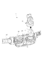
図4は、バックル20の装着部30の外部構造を示す拡大斜視図である。図5は、スタンプ10の裏面側及び前面側の構造を示す斜視図である。
装着部30は、図4に示すように、例えば前ハウジング30a及び後ハウジング30bの一対の組合せにて内部空間が形成されている。また、前ハウジング30aには、スタンプ10を上方から挿入装着可能な左右一対の突条の装着レール31を備えている。一対の装着レール31は、それぞれの突出先端部分が装着面30sに平行に屈曲して互いに向き合うフック片31fを備える。なお、装着面30sには、装着レール31間に、装着面30sから突出する後述する操作ピン35(図7参照)用の孔35h、受発光部28が設けられている。
FIG. 4 is an enlarged perspective view showing the external structure of the mounting portion 30 of the buckle 20. FIG. FIG. 5 is a perspective view showing the structure of the back side and front side of the stamp 10. FIG.
As shown in FIG. 4, the mounting portion 30 has an internal space formed by a pair of, for example, a front housing 30a and a rear housing 30b. Further, the front housing 30a is provided with mounting rails 31 having a pair of left and right ridges on which the stamp 10 can be inserted and mounted from above. The pair of mounting rails 31 includes hook pieces 31f whose protruding tip portions are bent in parallel with the mounting surface 30s and face each other. The mounting surface 30s is provided with a hole 35h for an operation pin 35 (see FIG. 7) projecting from the mounting surface 30s and a light emitting/receiving portion 28 between the mounting rails 31. As shown in FIG.

一方、スタンプ10は、その裏面側には、図5(a)に示すように、被装着面10sを構成する突出壁10cが設けられ、この突出壁10cの左右両端側に挿入係合片10dが設けられている。この挿入係合片10dは、突出壁10cの左右両側から張り出した形状でフック片31fの後側にスライドして挿入係合可能な構造となっている。したがって、スタンプ10は、挿入係合片10dをフック片31fの内側に挿入することで、装着面30sに対して被装着面10sが略密着するように装着される。 On the back side of the stamp 10, on the other hand, as shown in FIG. 5(a), a projecting wall 10c forming a mounting surface 10s is provided. is provided. The insertion engaging piece 10d projects from both the left and right sides of the protruding wall 10c, and has a structure in which it can be slid to the rear side of the hook piece 31f and can be inserted and engaged. Therefore, the stamp 10 is mounted such that the mounting surface 10s is substantially in close contact with the mounting surface 30s by inserting the insertion engagement piece 10d inside the hook piece 31f.

また、スタンプ10は、その本体11の形状が前述の如くチェスの駒の形をしており、後述するように上下動可能なスタンプ下端部12を備え、被装着面10sには、受発光部18、スタンプ回転スイッチ16用の開口16h、及びリセットスイッチ17が設けられている。また、天面側には、電源スイッチを兼ねる天面スイッチ14が設けられており、表側には、図5(b)に示すように、スタンプ10の特徴(例えばヒーローの特徴)を現わすモチーフ部10eが描かれている。このモチーフ部10eは、後述する内部の光源によって、光演出が行われる。 The main body 11 of the stamp 10 is in the shape of a chess piece as described above. , an opening 16h for the stamp rotation switch 16 and a reset switch 17 are provided. In addition, a top surface switch 14 that also serves as a power switch is provided on the top surface side, and on the front side, as shown in FIG. Portion 10e is depicted. The motif portion 10e is illuminated by an internal light source, which will be described later.

図6は、スタンプ10の装着状態における装着部30とスタンプ10の要部拡大断面図である。図6に示すように、スタンプ10の装着状態においては、被装着面10sの一方の開口部であるスタンプ側開口部18hと第1受発光素子18eとで構成されるスタンプ側の受発光部18は、装着面30sの他方の開口部である装着部側開口部28hと第2受発光素子28eとで構成される装着部側の受発光部28に対面(対向)している。本実施の形態において、装着部30にスタンプ10を装着した状態で、第1受発光素子18eは、第2受発光素子28eから送信された信号(赤外線発光)を受信(受光)可能であり、かつ第2受発光素子28eは、第1受発光素子18eから送信された信号(赤外線発光)を受信(受光)可能である。 FIG. 6 is an enlarged cross-sectional view of the main parts of the mounting portion 30 and the stamp 10 when the stamp 10 is mounted. As shown in FIG. 6, in the mounted state of the stamp 10, the stamp-side light emitting/receiving portion 18 includes a stamp side opening 18h, which is one opening of the mounting surface 10s, and a first light emitting/receiving element 18e. faces (opposes) a light emitting/receiving portion 28 on the side of the mounting portion, which is composed of an opening portion 28h on the side of the mounting portion, which is the other opening portion of the mounting surface 30s, and a second light emitting/receiving element 28e. In the present embodiment, with the stamp 10 attached to the attachment portion 30, the first light emitting/receiving element 18e can receive (receive) a signal (infrared light emission) transmitted from the second light emitting/receiving element 28e, In addition, the second light emitting/receiving element 28e is capable of receiving (light receiving) the signal (infrared light emission) transmitted from the first light emitting/receiving element 18e.

本実施形態において、第1受発光素子18eは、赤外線によってスタンプ10に対応する第1識別情報やコマンド情報等の制御情報を含む第1動作情報を送信可能であり、第2受発光素子28eは、赤外線によって第1識別情報とは別の第2識別情報やコマンド情報等の制御信号を含む第2動作情報を送信可能である。なお、ここで第1動作情報、第2動作情報は特に限定されるものではなく、それぞれの識別情報のみやコマンド情報等の制御情報のみ等であってもよい。 In this embodiment, the first light emitting/receiving element 18e can transmit first operation information including control information such as first identification information and command information corresponding to the stamp 10 by infrared rays, and the second light emitting/receiving element 28e Second identification information different from the first identification information and second operation information including control signals such as command information can be transmitted by infrared rays. Here, the first operation information and the second operation information are not particularly limited, and may be only their identification information or only control information such as command information.

第1受発光素子18e及び第2受発光素子28eは、赤外線の発光と受光が可能なLEDにて構成されている。このように、1つの素子同士を対面させることにより、スタンプ10とバックル20との間で信号を受信及び発信することができ、スタンプ10とバックル20との間で第1動作情報及び第2動作情報の相互の送受信が可能となる。 The first light emitting/receiving element 18e and the second light emitting/receiving element 28e are composed of LEDs capable of emitting and receiving infrared rays. Thus, by facing one element to another, signals can be received and transmitted between the stamp 10 and the buckle 20, and the first motion information and the second motion information can be transmitted between the stamp 10 and the buckle 20. Mutual transmission and reception of information becomes possible.

図6に示すように、第1受発光素子18eは、その先端部分がスタンプ側開口部18hに入り込むように設置され、一方、第2受発光素子28eにおいても、その先端部分が装着部側開口部28hに入り込むように設置されている。この結果、第1受発光素子18eと第2受発光素子28eとは、極めて接近した状態で対面している。 As shown in FIG. 6, the first light emitting/receiving element 18e is installed so that its tip portion enters the stamp side opening 18h, while the second light emitting/receiving element 28e also has its tip portion inserted into the mounting portion side opening. It is installed so as to enter the portion 28h. As a result, the first light emitting/receiving element 18e and the second light emitting/receiving element 28e face each other in extremely close proximity.

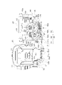
図7は、装着部30の内部構造を示す一部分解斜視図である。
装着部30は、装着部30の下端側から下方に向かって延出した下端突出部32が、本体部21内に設けられた軸部により、本体部21の前後方向に延びる回転中心C1を中心にして回転移動(揺動)可能に設けられている。
FIG. 7 is a partially exploded perspective view showing the internal structure of the mounting portion 30. As shown in FIG.
The mounting portion 30 has a lower end projecting portion 32 extending downward from the lower end side of the mounting portion 30. A shaft portion provided in the body portion 21 rotates the center of rotation C1 extending in the front-rear direction of the body portion 21. It is provided so as to be rotatable (oscillating).

装着部30は、下端突出部32が回転可能に支持されている他に、本体部21から装着部30の内部に突出する支持ピン部29によっても支持されている。すなわち、後ハウジング30bに設けられた円弧状の回転支持開口33を支持ピン部29が貫通していることで、装着部30が回転するときに、回転支持開口33が支持ピン部29にて案内される。また、支持ピン部29の屈曲した先端部29tによって後ハウジング30bが支持ピン部29から外れないように係止されている。 The mounting portion 30 is supported by a support pin portion 29 protruding into the mounting portion 30 from the body portion 21 in addition to the lower end projecting portion 32 being rotatably supported. That is, since the support pin portion 29 penetrates the circular rotation support opening 33 provided in the rear housing 30b, the rotation support opening 33 is guided by the support pin portion 29 when the mounting portion 30 rotates. be done. Further, the rear housing 30b is locked by the bent tip portion 29t of the support pin portion 29 so as not to come off the support pin portion 29. As shown in FIG.

装着部30には、図7に示すように、第2受発光素子28eに隣接して操作ピン35が設けられており、この操作ピン35が、スタンプ10の開口16h内に進入するように構成されている。詳細には、例えば、操作ピン35は、その基部を構成するピン基部35bが周囲の壁部35wにガイドされて装着部30の厚み方向に移動可能に設けられている。ピン基部35bは、前ハウジング30aとの間に基部圧縮ばね35cにより後ハウジング30b側に押圧されている。また、ピン基部35bに隣接してピン基部35bに係合可能にアーム部材36が設けられている。 As shown in FIG. 7, the mounting portion 30 is provided with an operation pin 35 adjacent to the second light emitting/receiving element 28e. It is Specifically, for example, the operation pin 35 is provided movably in the thickness direction of the mounting portion 30 with a pin base portion 35b constituting the base thereof being guided by a surrounding wall portion 35w. The pin base 35b is pressed toward the rear housing 30b by a base compression spring 35c between the pin base 35b and the front housing 30a. An arm member 36 is provided adjacent to the pin base portion 35b so as to be engageable with the pin base portion 35b.

アーム部材36は、アーム軸部36aを中心に、回転支持開口33内に進入するように設けられた第一アーム36bと、ピン基部35bの第一傾斜面35sに係合するように張り出した第二アーム36cと、を備えている。そして、第二アーム36cに設けられた第二傾斜面36sがピン基部35bに設けられた第一傾斜面35sに対して後ハウジング30b側から接触するように対面している。 The arm member 36 has a first arm 36b provided to enter the rotation support opening 33 around an arm shaft portion 36a, and a second arm member 36b projecting to engage with the first inclined surface 35s of the pin base portion 35b. and a second arm 36c. A second inclined surface 36s provided on the second arm 36c faces the first inclined surface 35s provided on the pin base portion 35b so as to come into contact therewith from the rear housing 30b side.

スタンプ10が装着部30に装着された状態において、装着部30を最大傾斜位置まで回転移動させる。これによって、アーム部材36は、第一アーム36bが支持ピン部29に当たり回転中心C4を中心にして回動する。これにより、第二傾斜面36sが第一傾斜面35sを押上げて、ピン基部35bを基部圧縮ばね35cの付勢力に抗して移動させる。したがって、操作ピン35は、スタンプ10の被装着面10sに配置されたスタンプ回転スイッチ16を押し込む。この結果、スタンプ10の音声や光による所定の演出が発現される。またスタンプ回転スイッチ16が押圧されることにより、第1受発光素子18eから動作情報を含む赤外線信号の送信が開始されるようにしてもよい。 With the stamp 10 mounted on the mounting portion 30, the mounting portion 30 is rotated to the maximum tilt position. As a result, the first arm 36b hits the support pin portion 29 and the arm member 36 rotates around the rotation center C4. As a result, the second inclined surface 36s pushes up the first inclined surface 35s to move the pin base 35b against the biasing force of the base compression spring 35c. Therefore, the operation pin 35 pushes the stamp rotation switch 16 arranged on the mounting surface 10s of the stamp 10 . As a result, the stamp 10 produces a predetermined effect with sound and light. Also, when the stamp rotation switch 16 is pressed, transmission of an infrared signal including operation information from the first light emitting/receiving element 18e may be started.

スタンプ台40は、箱型形状(図1及び図4参照)の台部ケーシング40bの一面(図中において上面)に、磁力によって画像形成が可能な磁気シート面43が設けられている。第1玩具体10の下端面に設けられた磁界発生手段であるスタンプ磁石13と接触させる(図1参照)ことで、例えば、磁気シート面43の表面にスタンプ磁石13に対応する画像(例えばスタンプ10のモチーフ部10eと同じ画像(図3参照)若しくはスタンプ10に関連する画像等)を表示することができる。 The stamp pad 40 has a magnetic sheet surface 43 on which an image can be formed by magnetic force on one surface (upper surface in the drawing) of a box-shaped base casing 40b (see FIGS. 1 and 4). An image (for example, a stamp 10 (see FIG. 3) or an image related to the stamp 10) can be displayed.

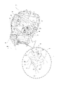
次に、装着部30の回転移動によってスタンプ台40を操作する連動機構について説明する。図8は、連動機構の動作前の状態で、連動機構を正面から見たときの内部斜視図である。図9は、連動機構の動作状態で、連動機構を下方側から見たときの内部斜視図である。 Next, an interlocking mechanism for operating the stamp pad 40 by rotating the mounting portion 30 will be described. FIG. 8 is an internal perspective view of the interlocking mechanism as viewed from the front before the interlocking mechanism operates. FIG. 9 is an internal perspective view of the interlocking mechanism when viewed from below in the operating state of the interlocking mechanism.

装着部30の回転動作は、連動機構50を介してスタンプ台40を回転移動するように伝達される。連動機構50は、大きく分けると、装着部30の下端突出部32に押されて本体部21の横方向にスライド移動するスライド部51と、スライド部51と接し回転中心C2を中心に回転する中間回転部52と、中間回転部52と噛み合って回転中心C3を中心にスタンプ台40を回転させる表示部回転部53と、を備える。 The rotational movement of the mounting section 30 is transmitted through the interlocking mechanism 50 so as to rotate the stamp pad 40 . The interlocking mechanism 50 can be broadly divided into a sliding portion 51 that slides in the horizontal direction of the main body portion 21 by being pushed by the lower end projecting portion 32 of the mounting portion 30, and an intermediate portion that contacts the sliding portion 51 and rotates about the rotation center C2. A rotating portion 52 and a display portion rotating portion 53 that meshes with the intermediate rotating portion 52 and rotates the stamp pad 40 about the center of rotation C3 are provided.

装着部30の下端突出部32には、円弧状の押圧面32sを備える押圧アーム32bが設けられている。スライド部51は、この押圧アーム32bに一端側51aが接する横長の部材であり、他端側51bが中間回転部52の下端レバー部52aを接触し押圧可能に配置されている。スライド部51の他端側51bの上部には、中間回転部52の回動を係止するロックピン52pを上方に押上げる押上げ突起51cが突設されている。また、スライド部51は、戻しばね51dが配置されており、初期位置に戻す方向に付勢されている。また、スライド部51には、ラバースイッチ等の装着部回転スイッチ27を押圧可能なスイッチ用突起51eが設けられている。すなわち、スライド部51の移動により装着部30の回転を検出する機構が設けられている。 A lower end projecting portion 32 of the mounting portion 30 is provided with a pressing arm 32b having an arcuate pressing surface 32s. The slide portion 51 is a horizontally long member with one end 51a in contact with the pressing arm 32b, and the other end 51b is arranged to contact and press the lower end lever portion 52a of the intermediate rotating portion 52. As shown in FIG. A push-up projection 51c that pushes up a lock pin 52p that locks the rotation of the intermediate rotary portion 52 is provided on the upper portion of the other end 51b of the slide portion 51. As shown in FIG. A return spring 51d is arranged on the slide portion 51, and the slide portion 51 is urged in the direction of returning to the initial position. Further, the slide portion 51 is provided with a switch protrusion 51e capable of pressing the mounting portion rotation switch 27 such as a rubber switch. That is, a mechanism is provided for detecting rotation of the mounting portion 30 by movement of the slide portion 51 .

中間回転部52は、スライド部51の他端側51bに押圧される下端レバー部52aを有するスプライン軸状の芯部材52bと、芯部材52bの外周面に噛合い且つ芯部材52bに対して軸方向に移動可能に設けられた環状係合部材52cと、環状係合部材52cの外周面に該外周面上を軸方向にスライド移動可能に設けられた第1歯車部材52dと、第1歯車部材52dの鍔部52eの外周縁の切込み52kに嵌合可能な係止爪52fを有するロックピン52pと、等を備えて回転中心C2を中心に回転する。 The intermediate rotating portion 52 has a spline shaft-like core member 52b having a lower end lever portion 52a that is pressed against the other end side 51b of the slide portion 51. a first gear member 52d provided on the outer peripheral surface of the annular engaging member 52c so as to be slidable in the axial direction on the outer peripheral surface; and a first gear member. A lock pin 52p having a locking pawl 52f that can be fitted into a notch 52k in the outer peripheral edge of the collar portion 52e of 52d, and the like are provided, and rotate around the center of rotation C2.

ここで、芯部材52bは、下端レバー部52aの一端が引張ばね52gにて初期位置に戻る方向に回転するように引っ張られている。また、環状係合部材52cは、芯部材52bを囲むように設けられた押圧ばね52hによって上方へ押されており、外周面に形成された複数の係合爪52mが第1歯車部材52dの内周縁側に設けられたラチェット爪52nに係合するように押されている。ロックピン52pは、ピン押圧ばね52iによってロック爪52qが第1歯車部材52dの外周縁の切込み52kに嵌合する方向(下方)に押されている。 Here, one end of the lower end lever portion 52a of the core member 52b is pulled by the tension spring 52g so as to rotate in the direction of returning to the initial position. Further, the annular engaging member 52c is pushed upward by a pressing spring 52h provided so as to surround the core member 52b, and a plurality of engaging claws 52m formed on the outer peripheral surface of the first gear member 52d. It is pressed so as to engage with a ratchet pawl 52n provided on the peripheral side. The lock pin 52p is pushed in a direction (downward) in which the lock claw 52q is fitted into the notch 52k of the outer peripheral edge of the first gear member 52d by a pin pressing spring 52i.

表示部回転部53は、回転中心C3を構成する支軸部材53aと、支軸部材53aに回転可能に軸支され下端側の歯部が第1歯車部材52dに係合する第2歯車部材53bと、第2歯車部材53bの上端側の歯部に内周が係合する環状部材53cと、環状部材53cの上側で支軸部材53aの先端部に係合する照明支持部材53dと、環状部材53cの外周面に形成された係合溝53eに弾性的に嵌入可能な一対の係合爪部材53fと、等を備えている。ここで、照明支持部材53dは、その長手方向の両端に光源を有する光出力部82が設けられており、磁気シート面43を内側から灯光するように構成されている。 The display portion rotating portion 53 includes a support shaft member 53a that forms a rotation center C3, and a second gear member 53b that is rotatably supported by the support shaft member 53a and whose teeth on the lower end side engage with the first gear member 52d. , an annular member 53c whose inner periphery is engaged with the tooth portion on the upper end side of the second gear member 53b, an illumination support member 53d engaged with the tip portion of the support shaft member 53a above the annular member 53c, and A pair of engaging claw members 53f that can be elastically fitted into engaging grooves 53e formed on the outer peripheral surface of 53c are provided. Here, the illumination support member 53d is provided with light output portions 82 having light sources at both ends in the longitudinal direction, and is configured to illuminate the magnetic sheet surface 43 from the inside.

また、環状部材53cに弾性係合している係合爪部材53fは、台ケーシング40a側に取り付けられており、環状部材53cとの係合によって装着部30に連動して台ケーシング40aが回転するように構成されている。したがって、例えば、スタンプ台40を無理やり回すような不測の操作が行われた場合には、係合爪部材53fとの係合が外れて空回りして、連動機構50の構成部品の破損防止機能を備えている。 An engaging claw member 53f elastically engaged with the annular member 53c is attached to the side of the base casing 40a, and the engagement with the annular member 53c causes the base casing 40a to rotate in conjunction with the mounting portion 30. is configured as Therefore, for example, when an unexpected operation such as forcibly rotating the stamp pad 40 is performed, the engagement with the engaging claw member 53f is disengaged and the stamp pad 40 rotates idly, thereby preventing damage to the component parts of the interlocking mechanism 50. I have.

このように構成された連動機構50においては、装着部30が回転(揺動)されると、スライド部51が図中右方向に移動する。このスライド部51の移動によって、ロックピン52pが上方に移動されて第1歯車部材52dのロックが解除され、芯部材52bが回転する。これにより、環状係合部材52cが回転し、環状係合部材52cの係合爪52mがラチェット爪52nに係合した状態で第1歯車部材52dを回転させる。第1歯車部材52dの回転によって、第2歯車部材53bが回転してスタンプ台40が180度回転する。スタンプ台40が所定の回転をした後は、戻しばね51dの付勢力により、装着部30は、初期位置(立った状態の位置)に戻される。一方、スタンプ台40は、第2歯車部材53bのつば部53jに形成された切欠き53kに係合する係止部材(不図示)にて位置決め係止される。また、中間回転部52は、ロックピン52pによってロック状態とされ、更に、芯部材52bは引張ばね52gによって初期位置に戻される。なお、係合爪52mは、ラチェット爪52nの傾斜面に接した状態で次の係合位置へ移動する。 In the interlocking mechanism 50 configured in this manner, when the mounting portion 30 is rotated (swinged), the slide portion 51 moves rightward in the figure. This movement of the slide portion 51 moves the lock pin 52p upward, unlocking the first gear member 52d, and rotating the core member 52b. As a result, the annular engaging member 52c rotates, and the first gear member 52d rotates while the engaging pawl 52m of the annular engaging member 52c is engaged with the ratchet pawl 52n. The rotation of the first gear member 52d rotates the second gear member 53b to rotate the stamp pad 40 180 degrees. After the stamp pad 40 rotates a predetermined amount, the mounting portion 30 is returned to the initial position (upright position) by the biasing force of the return spring 51d. On the other hand, the stamp pad 40 is positioned and locked by a locking member (not shown) that engages with the notch 53k formed in the collar portion 53j of the second gear member 53b. The intermediate rotating portion 52 is locked by the lock pin 52p, and the core member 52b is returned to the initial position by the tension spring 52g. The engaging pawl 52m moves to the next engaging position while being in contact with the inclined surface of the ratchet pawl 52n.

スタンプ台40は、図1に示すように、磁気シート面43が上向きになっている状態において、磁気シート面43にスタンプ10を押圧することにより磁気シート面43上に画像が形成され、その後、装着部30を移動(回転)することによって、図3に示すように、磁気シート面43が前方向きに回転した状態となる。この状態では、磁気シート面43に画像が形成されている。しかし、その後、装着部30を再度移動(回転)させることで、磁気シート面43が再び上を向くように移動(回転)する。このとき、上向きになった磁気シート面43には、画像は形成されておらず再び画像を形成可能な状態となる。すなわち、磁気シート面43が正面を向いている状態から上方を向くまでの間に画像が消去される構造を備えている。 As shown in FIG. 1, the stamp pad 40 forms an image on the magnetic sheet surface 43 by pressing the stamp 10 against the magnetic sheet surface 43 with the magnetic sheet surface 43 facing upward. By moving (rotating) the mounting portion 30, the magnetic sheet surface 43 rotates forward as shown in FIG. In this state, an image is formed on the magnetic sheet surface 43 . However, after that, by moving (rotating) the mounting portion 30 again, the magnetic sheet surface 43 moves (rotates) upward again. At this time, no image is formed on the magnetic sheet surface 43 facing upward, and the image can be formed again. That is, the magnetic sheet surface 43 has a structure in which the image is erased while the magnetic sheet surface 43 faces from the front to the upward direction.

図10は、画像表示部の画像形成可能状態における画像消去部材を示す側面図である。図11は、画像消去部材の分解斜視図である。図12は、画像消去部材の斜視図である。画像を消去する構造として、図10に示すように、スタンプ台40の中に、台ケーシング40aの内壁面の一面側に沿うように画像消去部材60が設けられている。この画像消去部材60は、図11及び図12に示すように、構成要素としては、図示の下から順に、第1動作部材61、第2動作部材62、及び第3動作部材63を備えている。 FIG. 10 is a side view showing the image erasing member in the image formable state of the image display section. FIG. 11 is an exploded perspective view of the image erasing member. FIG. 12 is a perspective view of an image erasing member. As a structure for erasing an image, as shown in FIG. 10, an image erasing member 60 is provided in the stamp pad 40 along one side of the inner wall surface of the base casing 40a. As shown in FIGS. 11 and 12, the image erasing member 60 includes, as constituent elements, a first operating member 61, a second operating member 62, and a third operating member 63 in order from the bottom of the drawing. .

第1動作部材61は、上端部61aには第1回動ピン61pが設けられ、この第1回動ピン61pが第2動作部材62の下端側の第1長孔62hに挿入されて、第2動作部材62に連結される。また、第1動作部材61は、圧縮ばね64により、その待機位置(初期位置)に戻る方向(図中下方)に付勢されている。第1動作部材61の下端部61bは、台ケーシング40aから下方に露出する。 The first operating member 61 is provided with a first rotating pin 61p at the upper end portion 61a. The first rotating pin 61p is inserted into the first elongated hole 62h on the lower end side of the second operating member 62 to 2 is connected to the operating member 62; Also, the first operating member 61 is urged by a compression spring 64 in a direction (downward in the drawing) to return to its standby position (initial position). A lower end portion 61b of the first operating member 61 is exposed downward from the base casing 40a.

第2動作部材62は、回転軸芯部62aが台ケーシング40a側に支持されて回動可能に設けられる。また、回転軸芯部62aを中心に下端側の第1長孔62hとは反対側に延出された一対の張出しアーム62bを有する。そして、この一対の張出しアーム62bの先端にそれぞれ設けられる第2回動ピン62pが第3動作部材63の第2長孔63hに挿入され連結される。 The second operating member 62 is rotatably provided with a rotation shaft core portion 62a supported on the base casing 40a side. It also has a pair of overhanging arms 62b extending in the opposite direction to the first elongated hole 62h on the lower end side from the rotation shaft core portion 62a. The second rotation pins 62p provided at the ends of the pair of projecting arms 62b are inserted into the second long holes 63h of the third operating member 63 and connected.

第3動作部材63は、磁気シート面43に対応する板状のキャンセラ磁石63aを保持する板面部63bを有し、板面部63bの一端側に第3回動ピン63pに貫通される回動軸部63cを中心に回転可能に台ケーシング40a側に取り付けられる。また、第3動作部材63は、引張ばね65により、磁気シート面43から離れる方向に引っ張られる。 The third operating member 63 has a plate surface portion 63b that holds a plate-shaped canceller magnet 63a corresponding to the magnetic sheet surface 43, and a rotation shaft penetrating a third rotation pin 63p at one end of the plate surface portion 63b. It is attached to the base casing 40a so as to be rotatable around the portion 63c. Also, the third operating member 63 is pulled away from the magnetic sheet surface 43 by the tension spring 65 .

図13は、画像表示部が正面を向いた状態における画像消去部材を示す一部分解斜視図である。図14は、画像消去部材の動作状態を示す側面図である。画像消去部材60は、スタンプ台40の回転と一緒に回転するが、所定の位置以外では、図13に示すように動作しない状態である。しかし、第1動作部材61の下端部61bが本体部21側に設けられた傾斜突起21bの位置にさしかかると、下端部61bが傾斜突起21bに当接しながら移動して、第1動作部材61が上方に押上げられる。これにより、図14に示すように、第3動作部材63が、キャンセラ磁石63aを磁気シート面43の裏面に接触又は接近するように動作する。より詳細には、第1動作部材61が圧縮ばね64の付勢力に抗して押上げられると、第2動作部材62は、回転軸芯部62aを中心に反時計回りの方向に回転する。これにより、第3動作部材63は、回動軸部63cを中心に時計回りの方向に回転する。この画像消去部材60の動作は、磁気シート面43が上を向いた状態から、270度回転した位置にて行われる。 FIG. 13 is a partially exploded perspective view showing the image erasing member with the image display portion facing the front. FIG. 14 is a side view showing the operating state of the image erasing member. The image erasing member 60 rotates together with the rotation of the stamp pad 40, but is in a non-moving state as shown in FIG. 13 except at a predetermined position. However, when the lower end portion 61b of the first operating member 61 reaches the position of the inclined projection 21b provided on the main body portion 21 side, the lower end portion 61b moves while contacting the inclined projection 21b, and the first operating member 61 moves. pushed upwards. As a result, as shown in FIG. 14, the third operating member 63 operates to bring the canceller magnet 63a into contact with or close to the back surface of the magnetic sheet surface 43. As shown in FIG. More specifically, when the first motion member 61 is pushed up against the biasing force of the compression spring 64, the second motion member 62 rotates counterclockwise about the rotation shaft core portion 62a. As a result, the third operating member 63 rotates clockwise about the rotation shaft portion 63c. The operation of the image erasing member 60 is performed at a position rotated 270 degrees from the state in which the magnetic sheet surface 43 faces upward.

図15は、スタンプ10の内部の要部破断拡大面図である。スタンプ10は、本体11の下端側のスタンプ下端部12に、磁界発生手段である例えば永久磁石にて構成されたスタンプ磁石13が設けられている。このスタンプ磁石13は、例えば、スタンプ10のモチーフ部10eと同じ図柄若しくは関連した図柄を模った磁石配列となっており、磁気シート面43に接触することで、磁気シート面43にスタンプ磁石13の図柄を転写・形成することができる。また、スタンプ下端部12は、第1玩具体10の本体11に対して移動可能に設けられている。例えば、スタンプ下端部12は、本体11の下端側の収容開口11aに上下移動可能に収容されている。また、スタンプ下端部12は、下端部押圧ばね12bにより本体11内側から外側に向かって押圧されている。したがって、スタンプ10を押す動作のときに、スタンプ下端部12が弾性的に引っ込むように動作する。 FIG. 15 is an enlarged fragmentary sectional view of the inside of the stamp 10. FIG. The stamp 10 is provided with a stamp magnet 13, which is a magnetic field generating means and is composed of, for example, a permanent magnet, at a stamp lower end portion 12 on the lower end side of a main body 11. As shown in FIG. The stamp magnet 13 has, for example, a magnet arrangement that mimics the same or related pattern as the motif portion 10 e of the stamp 10 . pattern can be transferred and formed. Also, the stamp lower end portion 12 is provided movably with respect to the main body 11 of the first toy body 10 . For example, the stamp lower end portion 12 is housed in a housing opening 11a on the lower end side of the main body 11 so as to be vertically movable. Further, the stamp lower end portion 12 is pressed outward from the inside of the main body 11 by a lower end portion pressing spring 12b. Therefore, when the stamp 10 is pushed, the stamp lower end 12 is elastically retracted.

また、スタンプ下端部12には、上方に向かって突出する突出壁12aが設けられており、突出壁12aにはテーパ面12tが形成されている。一方、突出壁12aの上方には、スタンプ10の前後方向にスライド移動可能なスライド操作片11sが設けられている。このスライド操作片11sには、テーパ面12tに対面する位置に対向テーパ面11tが形成されている。そして、スタンプ操作のときに、スタンプ下端部12が押されると、スライド操作片11sの対向テーパ面11tがテーパ面12tにより、図中左側に押されてラバースイッチのスタンプ押圧スイッチ15を押してスイッチ操作が行われる。これにより、LED等で構成された光出力部81スピーカの音出力部80にてスタンプ10の演出が発現される。なお、光出力部81は、スタンプ10の前方に向かって光を灯光するように配置されており、これにより、スタンプ10の先方側に設けられたモチーフ部10eを光らせることができる。 A protruding wall 12a that protrudes upward is provided at the lower end portion 12 of the stamp, and a tapered surface 12t is formed on the protruding wall 12a. On the other hand, above the projecting wall 12a, a slide operation piece 11s that can slide in the front-rear direction of the stamp 10 is provided. A facing tapered surface 11t is formed on the slide operation piece 11s at a position facing the tapered surface 12t. When the stamp lower end portion 12 is pressed during stamp operation, the taper surface 11t of the slide operation piece 11s is pressed leftward in the figure by the tapered surface 12t, and the stamp pressing switch 15 of the rubber switch is pressed to operate the switch. is done. As a result, the effect of the stamp 10 is produced by the sound output section 80 of the light output section 81 speaker composed of an LED or the like. The light output portion 81 is arranged so as to emit light toward the front of the stamp 10, so that the motif portion 10e provided on the front side of the stamp 10 can be illuminated.

図16は、演出出力玩具1における制御系のブロック図である。本実施形態における制御部70は、スタンプ10側の第1制御部71とバックル20側の第2制御部72で構成される。スタンプ10の第1制御部71には、1つの第1受発光素子18e、天面スイッチ14(電源スイッチ)、スタンプ押圧スイッチ15、スタンプ回転スイッチ16、リセットスイッチ17が接続されている。また、第1制御部71には、記憶部73が接続されている。記憶部73には、演出時に例えば、所定の台詞,起動音、変身音、必殺技キメ音等の音を音出力部80から発生させるための音楽・音声データ、光出力部81の発光色、発光パターンなどの発光データが記憶されている。また、記憶部73は、読取り情報を、一時的に記憶する一時記憶領域を有している。また、第1制御部71には、駆動部74が接続され、この駆動部74には、音出力部80、光出力部81が接続されている。スタンプ10は、スタンプ10側の第1識別情報と受信した第2識別情報との両情報に基づく情報によって、音出力部80及び光出力部81にて所定の演出を発現する。 FIG. 16 is a block diagram of the control system in the effect output toy 1. As shown in FIG. The control unit 70 in this embodiment includes a first control unit 71 on the stamp 10 side and a second control unit 72 on the buckle 20 side. The first control unit 71 of the stamp 10 is connected to one first light emitting/receiving element 18e, top panel switch 14 (power switch), stamp press switch 15, stamp rotation switch 16, and reset switch 17. FIG. A storage unit 73 is also connected to the first control unit 71 . The storage unit 73 stores music/audio data for causing the sound output unit 80 to generate sounds such as predetermined lines, startup sounds, transformation sounds, finishing touch sounds, etc., light emission colors of the light output unit 81, Light emission data such as light emission patterns are stored. The storage unit 73 also has a temporary storage area for temporarily storing read information. Further, a drive section 74 is connected to the first control section 71 , and a sound output section 80 and a light output section 81 are connected to the drive section 74 . The stamp 10 expresses a predetermined effect in the sound output section 80 and the light output section 81 based on information based on both the first identification information on the stamp 10 side and the received second identification information.

バックル20の第2制御部72には、1つの第2受発光素子28e、電源スイッチ24、スタンプ台スイッチ26、装着部回転スイッチ27が接続されている。また、第2制御部72には、記憶部76が接続されている。記憶部76には、光出力部82の発光色、発光パターンなどの発光データが記憶されている。また、記憶部76は、読取り情報を、一時的に記憶する一時記憶領域を有している。また、第2制御部72には、駆動部77が接続され、この駆動部77には、光出力部82が接続されている。バックル20においても、バックル20側の第2識別情報と受信した第1識別情報との両情報に基づいて所定の演出を発現する。 The second control section 72 of the buckle 20 is connected to one second light emitting/receiving element 28 e , the power switch 24 , the stamp pad switch 26 and the mounting section rotation switch 27 . A storage unit 76 is also connected to the second control unit 72 . The storage unit 76 stores light emission data such as the light emission color and light emission pattern of the light output unit 82 . The storage unit 76 also has a temporary storage area for temporarily storing read information. Further, the driving section 77 is connected to the second control section 72 , and the optical output section 82 is connected to the driving section 77 . The buckle 20 also produces a predetermined effect based on both the second identification information on the buckle 20 side and the received first identification information.

また、スタンプ10をバックル20に装着した状態において、第1制御部71は、第1受発光素子18eが第2受発光素子28eからの第2動作情報を受信したことを契機に第1玩具体10の演出出力を実行し、また、第1玩具体10の演出出力の実行が完了した後(第1玩具体10の所定の演出出力が終了した後)、第1受発光素子18eから第2受発光素子28eに第1動作情報を送信する。また、第2制御部72は、第2受発光素子28eが第1受発光素子18eからの第1動作情報を受信したことを契機に第2玩具体20の演出出力を実行し、また、第2玩具体の演出出力の実行が完了した後(第2玩具体20の所定の演出出力が終了した後)、第2受発光素子28eから第1受発光素子18eに第2動作情報を送信する。このように、第1受発光素子18eから第2受発光素子28eへの第1動作情報の送信と、第2受発光素子28eから第1受発光素子18eへの第2動作情報の送信と、が交互に行われる設定を有し、スタンプ10とバックル20との間で相互演出による掛け合い演出を実行することができる Further, in the state where the stamp 10 is attached to the buckle 20, the first control unit 71 controls the first toy body when the first light emitting/receiving element 18e receives the second operation information from the second light emitting/receiving element 28e. 10, and after the execution of the effect output of the first toy body 10 is completed (after the predetermined effect output of the first toy body 10 is completed), the first light emitting/receiving element 18e to the second The first operation information is transmitted to the light emitting/receiving element 28e. Further, the second control unit 72 executes the effect output of the second toy body 20 when the second light emitting/receiving element 28e receives the first action information from the first light emitting/receiving element 18e. After the execution of the effect output of the two toy bodies is completed (after the predetermined effect output of the second toy body 20 is completed), the second action information is transmitted from the second light emitting/receiving element 28e to the first light emitting/receiving element 18e. . Thus, the transmission of the first operation information from the first light receiving/emitting element 18e to the second light emitting/receiving element 28e, the transmission of the second operation information from the second light emitting/receiving element 28e to the first light emitting/receiving element 18e, is alternately performed, and a interaction effect can be executed by mutual effect between the stamp 10 and the buckle 20

(変形例1)
第1玩具体の変形例1として、図17を参照して説明する。スタンプ10は、チェスの6種類の駒の内、例えばルーク(戦車)を模ったルーク型といえるが、このルーク型のスタンプ10において、外観的にはモチーフ部10eが異なるスタンプ10を複数用意することで、他のヒーローの異なる演出が可能である。この場合、モチーフ部10eが相違するだけでなく、スタンプ下端部12のスタンプ磁石13による画像もモチーフ部10eに合わせて変更される。また、複数のスタンプ10は、それぞれ個別の識別情報を備え、当該識別情報を赤外線信号に乗せて送信することにより、スタンプ10の種類を識別することができる。
(Modification 1)
Modification 1 of the first toy will be described with reference to FIG. The stamp 10 can be said to be of a rook type modeled after, for example, a rook (chariot) among the six types of chess pieces. By doing so, different productions of other heroes are possible. In this case, not only the motif portion 10e is different, but also the image formed by the stamp magnet 13 on the bottom end portion 12 of the stamp is changed in accordance with the motif portion 10e. Further, each of the plurality of stamps 10 has individual identification information, and the type of stamp 10 can be identified by transmitting the identification information on an infrared signal.

更に、図17に示すような5種類のスタンプを追加したコレクションとして用意することができる。図17に示したものは、前掲のものを含めてチェスの駒に見立てた6種類のスタンプ形状としている。例えば、モチーフ部10eが第1恐竜形状の前掲のルーク(戦車)型のスタンプ10に加えて、例えば、鳥形状のモチーフ部10eを有するポーン(兵隊)型のスタンプ10A、白馬形状のモチーフ部10eを有するナイト(騎士)型のスタンプ10B、第2恐竜形状のモチーフ部10eを有するビショップ(僧侶)型のスタンプ10C、植物形状のモチーフ部10eを有するクイーン(女王)型のスタンプ10D、第3恐竜形状のモチーフ部10eを有するキング(王様)型のスタンプ10E、というように設定して、スタンプ下端部12のスタンプ磁石も各モチーフ部10eに対応させた画像が形成されるようにして、その種類毎の音声、光、画像の演出種類を楽しむことができる。 Furthermore, it is possible to prepare a collection in which five kinds of stamps as shown in FIG. 17 are added. The stamps shown in FIG. 17 have six types of stamp shapes, including those shown above, which are likened to chess pieces. For example, in addition to the above-mentioned rook (tank) stamp 10 whose motif part 10e is the first dinosaur shape, for example, a pawn (soldier) stamp 10A having a bird-shaped motif part 10e, and a white horse-shaped motif part 10e. , a bishop-type stamp 10C having a second dinosaur-shaped motif portion 10e, a queen-type stamp 10D having a plant-shaped motif portion 10e, and a third dinosaur A king type stamp 10E having a shaped motif portion 10e is set, and the stamp magnet at the bottom end portion 12 of the stamp is also formed with an image corresponding to each motif portion 10e. You can enjoy different types of sound, light, and image effects.

(変形例2)
第2玩具体の変形例2について、図18~図20を参照して説明する。図18に示すように、本変形例においては、武器仕様の第2玩具体20A(以下、「武器20A」という)は、銃、及び手斧の両方の形状を模した構成となっている。武器20Aは、銃として遊戯をする場合或いは手斧として遊戯をする場合があり、銃としての遊戯の場合には、第1握り部(第1把持部)20gを手指にて握って使用する一方、手斧としての遊戯の場合には、第2握り部(第2把持部)20hを握るようにして使用する。すなわち、手斧の場合においては、第1握り部20gの下端部を手斧の刃部20kとして見立てた構成となる。
(Modification 2)
Modification 2 of the second toy body will be described with reference to FIGS. 18 to 20. FIG. As shown in FIG. 18, in this modification, a weapon-specific second toy body 20A (hereinafter referred to as "weapon 20A") has a configuration that imitates the shape of both a gun and a hatchet. The weapon 20A may be played as a gun or as a hand axe. When playing as a gun, the first grip portion (first grip portion) 20g is gripped with fingers, In the case of playing as a hatchet, it is used by gripping the second grip portion (second grip portion) 20h. That is, in the case of a hatchet, the lower end portion of the first grip portion 20g is configured as the blade portion 20k of the hatchet.

スタンプ台40は、第1握り部20gの近傍、例えば第1握り部20gの上部に設けられている。また、スタンプ10を装着する部位は、スタンプ台40の上部の第1装着部34a及び銃身の先端側の第2装着部34bの2箇所となっている。スタンプ10側の受発光部18と武器20A側の受発光部28(不図示)は、両装着部34a,34bに設けても良いが、第1装着部34a或いは第2装着部34bに設けた構成であってもよい。 The stamp pad 40 is provided near the first grip portion 20g, for example, above the first grip portion 20g. The stamp 10 is mounted at two locations, a first mounting portion 34a on the top of the stamp pad 40 and a second mounting portion 34b on the tip side of the barrel. The light emitting/receiving portion 18 on the stamp 10 side and the light emitting/receiving portion 28 on the weapon 20A side (not shown) may be provided on both mounting portions 34a and 34b, but they are provided on the first mounting portion 34a or the second mounting portion 34b. It may be a configuration.

第2玩具体20Aの遊び方としては、銃としての遊戯状態の場合には、第1握り部20gに設けられた引き金としての第1トリガーボタン(第1操作部)20mを利用する。一方、手斧としての遊戯状態の場合には、第2握り部20hに設けられた第2トリガーボタン(第2操作部)20nを利用する。また、両方のスタンプ10については、スタンプ下端部12が操作しやすい状態(スタンプ10が横向に装着されている)となっているので、スタンプ下端部12を手で操作することができる。 As for how to play the second toy body 20A, in the play state as a gun, the first trigger button (first operating portion) 20m as a trigger provided on the first grip portion 20g is used. On the other hand, in the play state as a hatchet, the second trigger button (second operating portion) 20n provided on the second grip portion 20h is used. In addition, since the lower end portions 12 of both stamps 10 are in an easy-to-operate state (the stamps 10 are mounted horizontally), the lower end portions 12 of the stamps can be operated by hand.

また、スタンプ台40に形成された画像は、例えば、第1トリガーボタン20mや第2トリガーボタン20nの操作にて消去する行うことができる。なお、武器20Aは、電源スイッチ及びリセットスイッチ(不図示)等は、スタンプ台40が設けられた側とは反対側(図示の裏側)に設けられている。 Also, the image formed on the stamp pad 40 can be erased by operating the first trigger button 20m or the second trigger button 20n, for example. In the weapon 20A, a power switch, a reset switch (not shown), etc. are provided on the side opposite to the side on which the stamp pad 40 is provided (back side in the drawing).

また、スタンプ10の取付け構造は、図19に示すように、例えば、スタンプ下端部12を銃口側に向けた状態で、銃口側からスライド移動させて挿入する構造である。すなわち、スタンプ10の挿入するときの向きが図1に示した装着部30の場合とは逆になるだけで両装着部34a,34bの挿入構造は同じ構造である。 Also, as shown in FIG. 19, the mounting structure of the stamp 10 is, for example, a structure in which the lower end portion 12 of the stamp faces the muzzle side and is slid and inserted from the muzzle side. That is, the inserting structure of both mounting portions 34a and 34b is the same except that the direction of insertion of the stamp 10 is opposite to that of the mounting portion 30 shown in FIG.

なお、スタンプ10の装着後の係止構造としては、例えば、両装着部34a,34bに設けられた係止突起38がスタンプ10の裏面側に設けられた係合凹部10m(図5参照)に嵌入する構造とする。また、スタンプ10の取り外しは、例えば、係止突起38が取付け面から引っ込むように動作させる取り外しボタン39を用いることができる。 As for the locking structure after the stamp 10 is mounted, for example, the locking protrusions 38 provided on both mounting portions 34a and 34b are engaged with the engaging recesses 10m (see FIG. 5) provided on the back side of the stamp 10. The structure should be inset. Also, the stamp 10 can be removed using, for example, a removal button 39 that causes the locking projection 38 to retract from the mounting surface.

図18及び図19に示した武器20Aにおいては、バックル20に使用するスタンプ10と共通のものを使用したが、図20に示すように、武器専用のスタンプ10Gを用いるようにしても良い。図20においては、銃口(銃身の先端)に設けるスタンプ10Gは、例えば、天面スイッチ14の部位が円筒形に凹んだ窪み部10jとされている。一方、第2装着部34bは、窪み部10jに嵌入する円筒挿入部34jを備えており、円筒挿入部34jに窪み部10jを嵌合して装着する。このような嵌着構造により、銃口部分の形状が図19に示す構造よりもシンプルとなる。これにより、第2装着部34bにスタンプ10Gを装着するときの装着・操作感が、例えば銃弾を装填するような操作感を醸し出すことができる。また、銃身の下側には、銃身の長手方向に沿ってスライド移動する銃身下スライド部20rが設けられており、例えば、この銃身下スライド部20rのスライド移動によって、スタンプ台40の画像を消すようにしても良い。 In the weapon 20A shown in FIGS. 18 and 19, a stamp 10 common to the buckle 20 is used, but as shown in FIG. 20, a weapon-specific stamp 10G may be used. In FIG. 20, the stamp 10G provided at the muzzle (the tip of the barrel) has, for example, a recess 10j in which the top surface switch 14 is recessed into a cylindrical shape. On the other hand, the second mounting portion 34b has a cylindrical insertion portion 34j that fits into the recessed portion 10j, and the cylindrical insertion portion 34j is fitted with the recessed portion 10j. Such fitting structure makes the shape of the muzzle portion simpler than the structure shown in FIG. As a result, when the stamp 10G is attached to the second attachment portion 34b, the feeling of attachment and operation can be similar to that of loading a bullet, for example. Further, a barrel-under slide portion 20r is provided on the underside of the barrel to slide along the longitudinal direction of the barrel. You can do it.

以下、演出出力玩具1の遊び方、演出の一例について説明する。
(スタンプ10及びバックル20を使用した遊び)
なお、遊び方には、例えば、主人公(ヒーロー)の変身モード、必殺技モード、2段変身モードの際の音や光の出力、変身後の必殺技のキメ音や光を出力するようになっている。ここでは、例えば、特定のヒーローの変身バージョンの一例について述べる。
An example of how to play the production output toy 1 and an example of production will be described below.
(Play with stamp 10 and buckle 20)
In addition, how to play, for example, the output of sound and light when the main character (hero) transformation mode, special move mode, two-stage transformation mode, and the texture sound and light of the special move after transformation are output. there is Here, for example, one example of a transformed version of a particular hero is described.

先ず、操作者は、バックル20の電源スイッチ24(例えば、バックル裏面側に設けられた)をオン(起動音)にし、操作を開始する。そして、変身前のヒーローとして、スタンプ10の天面スイッチ14(電源スイッチ)をオンにする。このとき、音出力部80にて起動音が発現され、更に光出力部81が発光しスタンプ10のモチーフ部10eに内側から光が当てられる。この演出は、例えば、デジタルグラフィックが投影されるイメージを演出する。また、スタンプ10に設けられた第1受発光素子18eはオン状態(赤外線受光状態)となる。 First, the operator turns on the power switch 24 (for example, provided on the back side of the buckle) of the buckle 20 (activation sound) to start the operation. Then, as a pre-transformation hero, the top surface switch 14 (power switch) of the stamp 10 is turned on. At this time, the sound output section 80 produces a start-up sound, and the light output section 81 emits light to illuminate the motif portion 10e of the stamp 10 from the inside. This presentation, for example, presents an image on which a digital graphic is projected. Also, the first light emitting/receiving element 18e provided on the stamp 10 is turned on (infrared light receiving state).

その後、スタンプ10のスタンプ下端部12をスタンプ台40の上面(磁気シート面43)に合わせるように押す(図1参照)。これにより、磁気シート面43上にモチーフ部10eに関連した画像が形成される。このスタンプ押し操作により、スタンプ下端部12がスタンプ内方に移動してスタンプ押圧スイッチ15が押される。更に、バックル20側においては、磁気シート面43が押されこれに連動する押圧部材44(図8及び図9参照)にてスタンプ台スイッチ26(図8及び図9参照)がオンになり、光出力部82が発光する。このスタンプ10の押印操作を、デジタル認証操作として演出し、更に、スタンプ台40上の画像形成によって、スタンプモチーフの力を認証として演出し、その結果、エフェクトが出現する、という演出が行われる。なお、スタンプ10の押圧で、バックル20に設けられた第2受発光部28eの赤外線はオン状態(赤外線発光状態)となる。 Thereafter, the stamp lower end portion 12 of the stamp 10 is pressed so as to align with the top surface (magnetic sheet surface 43) of the stamp pad 40 (see FIG. 1). As a result, an image related to the motif portion 10 e is formed on the magnetic sheet surface 43 . By this stamp pressing operation, the stamp lower end portion 12 moves inward of the stamp and the stamp pressing switch 15 is pressed. Further, on the side of the buckle 20, the magnetic sheet surface 43 is pressed, and the stamp pad switch 26 (see FIGS. 8 and 9) is turned on by the pressing member 44 (see FIGS. 8 and 9) which is interlocked therewith. The output section 82 emits light. The stamping operation of the stamp 10 is produced as a digital authentication operation, and furthermore, the power of the stamp motif is produced as authentication by image formation on the stamp pad 40, and as a result, an effect is produced. By pressing the stamp 10, the infrared rays of the second light emitting/receiving portion 28e provided on the buckle 20 are turned on (infrared emitting state).

その後、スタンプ10を、バックル20の装着部30に装着する。スタンプ10に設けられた第1受発光素子18eと、バックル20の装着部30に設けられた第1受発光素子18eが対向し、第2受発光素子28eから発光する赤外線を第1受発光部18eが受光することにより、バックル20からスタンプ10に対して動作信号が送信される。これにより、スタンプ10側では、装填音と共に発光が発現される。バックル20側では、スタンプ10にてスタンプ台を押されたときの発光が引き続いて行われている。なお、第2受発光素子28eから送信される第2動作情報には、バックル20に関する第2識別情報とスタンプ10の演出出力に関するコマンド情報等の制御情報が含まれ、第1受発光部18eにおいて当該第2動作情報を受信することにより、スタンプ10はバックル20に装着されていることを認識し、第2識別情報に対する当該制御情報に応じた演出を出力する。 After that, the stamp 10 is attached to the attachment portion 30 of the buckle 20 . The first light emitting/receiving element 18e provided on the stamp 10 faces the first light emitting/receiving element 18e provided on the mounting portion 30 of the buckle 20, and the infrared light emitted from the second light emitting/receiving element 28e is transmitted to the first light emitting/receiving portion. An operation signal is transmitted from the buckle 20 to the stamp 10 by the light received by 18e. As a result, on the stamp 10 side, light is emitted together with the loading sound. On the buckle 20 side, the stamp 10 continues to emit light when the stamp pad is pressed. The second action information transmitted from the second light emitting/receiving element 28e includes control information such as second identification information regarding the buckle 20 and command information regarding the effect output of the stamp 10. By receiving the second action information, the stamp 10 recognizes that it is attached to the buckle 20, and outputs an effect according to the control information for the second identification information.

スタンプ10の装着後、スタンプ10を装着部30と一緒に右に大きく傾けるように移動(回転)する。装着部30の移動(回転)によって、装着部回転スイッチ27がスライド部51にて押され、第2受発光部28eから新たな動作情報を含む赤外線信号が送信され、第1受発光部18eで第2受発光部28eからの赤外線信号を受信することにより、スタンプ10において、変身レバー音、変身音楽、等の音出力及び光出力による演出が行われる。また、第1受発光部18eで第2受発光部28eからの赤外線信号を受信してスタンプ10からの所定の演出出力が完了した後、第1受発光部18eから第2受発光部28eに向けて赤外線信号(第1動作情報)の送信が開始され、当該赤外線信号を受信したバックル20において、変身発光演出が行われ、ヒーローの変身が完了する。なお、第1受発光素子18eから送信される第1動作情報には、スタンプ10に関する第1識別情報とバックル20の演出出力に関するコマンド情報等の制御情報が含まれ、第2受発光部28eにおいて当該第1動作情報を受信することにより、バックル20は装着されているスタンプ10の種類を認識し、第1識別情報に対する当該制御情報に応じた演出を出力する。 After the stamp 10 is mounted, the stamp 10 is moved (rotated) together with the mounting portion 30 so as to tilt greatly to the right. Due to the movement (rotation) of the mounting section 30, the mounting section rotation switch 27 is pushed by the sliding section 51, an infrared signal containing new operation information is transmitted from the second light emitting/receiving section 28e, and the first light emitting/receiving section 18e By receiving the infrared signal from the second light emitting/receiving portion 28e, the stamp 10 performs sound output and light output such as transformation lever sound and transformation music. Further, after the first light emitting/receiving portion 18e receives the infrared signal from the second light emitting/receiving portion 28e and the predetermined effect output from the stamp 10 is completed, Transmission of an infrared signal (first action information) is started toward the player, and the buckle 20 that receives the infrared signal performs a transformation lighting effect, completing the transformation of the hero. The first operation information transmitted from the first light emitting/receiving element 18e includes first identification information about the stamp 10 and control information such as command information about the effect output of the buckle 20. By receiving the first action information, the buckle 20 recognizes the type of the attached stamp 10 and outputs an effect according to the control information for the first identification information.

ここで、装着部30の移動(回転)によって、スタンプ台40は、磁気シート面43が前方に向く状態に移動(回転)され、スタンプ10のモチーフ部10eとスタンプ台40の画像とが前方から並んで見えるようになる。 Here, by moving (rotating) the mounting portion 30, the stamp pad 40 is moved (rotated) so that the magnetic sheet surface 43 faces forward, and the motif portion 10e of the stamp 10 and the image of the stamp pad 40 are displayed from the front. They can be seen side by side.

変身モードが完了した後の待機状態(スタンプ10が装着された状態で、直立した初期位置状態)において、例えば、スタンプ10を再び倒すように操作すると、スタンプ台40の磁気シート面43が上方に向くように移動(回転)し、磁気シート面43の表示が消去される。それとともに、第1受発光部18eと第2受発光部28eとの間で信号の送受信が行われ、スタンプ10およびバックル20において、発光や発音の演出(必殺技演出)が行われる。また、この状態でスタンプ10の天面スイッチ14を押した後にスタンプ10を倒すように回転移動すると、第1受発光部18eと第2受発光部28eとの間で信号の送受信が行われ、スタンプ10およびバックル20において、発光や発音の演出(2段必殺技演出)が行われる。 When the stamp 10 is tilted again in the standby state after the transformation mode is completed (the stamp 10 is in an upright initial position), the magnetic sheet surface 43 of the stamp pad 40 is turned upward. It moves (rotates) so as to face it, and the display on the magnetic sheet surface 43 is erased. At the same time, signals are transmitted and received between the first light emitting/receiving portion 18e and the second light emitting/receiving portion 28e, and the stamp 10 and the buckle 20 perform light emission and sound effects (deathblow effects). In this state, when the top surface switch 14 of the stamp 10 is pressed and then the stamp 10 is rotated so as to fall down, signals are transmitted and received between the first light emitting/receiving portion 18e and the second light emitting/receiving portion 28e. At the stamp 10 and the buckle 20, an effect of light emission and sound (two-stage deathblow effect) is performed.

ここで、異なるモチーフ部10eを有するスタンプ10は、モチーフ毎の第1識別情報を持っているので、スタンプ10毎のモチーフに合わせた音声、発光色、発光パターンの演出を楽しむことができる。 Here, stamps 10 having different motif parts 10e have the first identification information for each motif, so that it is possible to enjoy the effects of sound, luminous color, and luminous pattern matched to the motif of each stamp 10.例文帳に追加

(スタンプ10の単独の遊び)
スタンプ10の単独の遊び方としては、例えば、スタンプ下端部12を押す操作によりスタンプ押し音と共に所定の発光色にて発光演出を行うことができる。また、天面スイッチ14を押す操作によって、そのモチーフに合わせたスタンプ起動音と共に所定色によって発光演出が行われる。なお、スタンプ10を装着部30から取り外したときには、短い取り外し音が発現される。
(Stamp 10 solo play)
As for how to play the stamp 10 alone, for example, by pressing the lower end portion 12 of the stamp, it is possible to perform a light emitting effect in a predetermined color along with a stamp pressing sound. In addition, by pressing the top panel switch 14, a stamp activation sound matching the motif and a light emitting effect in a predetermined color are performed. Note that when the stamp 10 is removed from the mounting portion 30, a short removal sound is produced.

(武器仕様の遊び)
スタンプ10を武器20Aに装着する場合の遊び方としては、例えば、スタンプ10を装着することで、スタンプ10と武器20Aとの赤外線送受信が可能となり、スタンプ10から送信される第1動作信号や武器20Aから送信される第2動作信号のやりとりにより、装填音及び発光を発現させることができる。この音及び光の演出については、スタンプ10側の発現だけでなく、武器20A側からも発現させることができる。
(Weapon-specific play)
As for how to play when the stamp 10 is attached to the weapon 20A, for example, attaching the stamp 10 enables infrared transmission and reception between the stamp 10 and the weapon 20A. The loading sound and light emission can be produced by exchanging the second operation signal transmitted from the . This sound and light effect can be produced not only from the stamp 10 side but also from the weapon 20A side.

例えば、武器20Aに設けられた第2受発光素子28eから送信される第2動作情報には、武器20Aに関連する第2識別情報とスタンプ10の演出出力に関するコマンド情報等の制御情報が含まれ、第1受発光部18eにおいて当該第2動作情報を受信することにより、スタンプ10は武器20Aに装着されていることを認識し、第2識別情報に対する当該制御情報に応じた演出を出力する。 For example, the second action information transmitted from the second light emitting/receiving element 28e provided on the weapon 20A includes second identification information related to the weapon 20A and control information such as command information related to the effect output of the stamp 10. By receiving the second action information at the first light emitting/receiving section 18e, the stamp 10 recognizes that it is attached to the weapon 20A, and outputs an effect according to the control information for the second identification information.

また、スタンプ10に設けられた第1受発光素子18eから送信される第1動作情報には、スタンプ10に関連する第1識別情報と武器20Aの演出出力に関するコマンド情報等の制御情報が含まれ、第2受発光部28eにおいて当該第1動作情報を受信することにより、武器20Aは装着されているスタンプ10の種類を認識し、第1識別情報に対する当該制御情報に応じた演出を出力する。また、武器特有の必殺モードについても、第1及び第2トリガーボタン20m,20nの操作によって銃撃音や斧撃音にあわせて発光演出を行う。また、スタンプ10の天面スイッチ14を操作し、その後、銃の第1トリガーボタン20m、或いは手斧の第2トリガーボタン20nを操作することで、スタンプ10のモチーフ部10eの図柄に合わせた特有の演出を行うことができる。 The first action information transmitted from the first light emitting/receiving element 18e provided on the stamp 10 includes first identification information related to the stamp 10 and control information such as command information related to the effect output of the weapon 20A. By receiving the first action information at the second light emitting/receiving section 28e, the weapon 20A recognizes the type of the attached stamp 10 and outputs an effect according to the control information for the first identification information. Also, in the deadly mode peculiar to the weapon, light emission effects are performed in accordance with the shooting sound and the ax shooting sound by operating the first and second trigger buttons 20m and 20n. In addition, by operating the top surface switch 14 of the stamp 10, and then operating the first trigger button 20m of the gun or the second trigger button 20n of the hatchet, a unique pattern matching the pattern of the motif part 10e of the stamp 10 can perform.

また、変身モード、武器モードの何れにおいても、スタンプ10は、そのモチーフに合わせた特色を発現するものである。例えば、装着音、待機音、必殺技音、台詞、発光色、発光パターン、などを種々の演出要素がモチーフ毎に変更されており、多様な演出モードを出力することができる。 Moreover, the stamp 10 expresses a feature that matches the motif in both the transformation mode and the weapon mode. For example, various production elements such as wearing sound, standby sound, deathblow sound, dialogue, light emission color, light emission pattern, etc. are changed for each motif, and various production modes can be output.

本実施形態の演出出力玩具1によれば、スタンプ10側の1つの第1受発光素子18eと、バックル20(武器20Aを含む)の1つの第2受発光素子28eと、を対面配置させる構造が採用されていることで、位置合わせが容易で正確な位置合わせができるので、双方の部材が保持している固有の情報(第1識別情報、第2識別情報等)を確実且つ正確に送受信することができる。この結果、赤外線を使用した通信であっても、スタンプ10側の固有情報とバックル20側の固有情報との両情報に基づく情報によって、通信エラーのないきわめ正確な演出を実現することができ、演出出力玩具1として興趣性の高い玩具を提供できる。 According to the effect output toy 1 of the present embodiment, one first light emitting/receiving element 18e on the stamp 10 side and one second light emitting/receiving element 28e of the buckle 20 (including the weapon 20A) are arranged facing each other. By adopting , positioning is easy and accurate, so unique information (first identification information, second identification information, etc.) held by both members can be reliably and accurately transmitted and received. can do. As a result, even in the case of communication using infrared rays, it is possible to realize an extremely accurate presentation without communication errors by information based on both the unique information on the stamp 10 side and the unique information on the buckle 20 side. A highly entertaining toy can be provided as the performance output toy 1.例文帳に追加

また、本実施形態の演出出力玩具1においては、第1受発光素子18eが第2受発光素子28eからの第2動作情報を受信したことを契機として、第1玩具体10の演出出力を実行し、第2受発光素子28eが第1受発光素子18eからの第1動作情報を受信したことを契機として、第2玩具体20の演出出力を実行する、というような、相互演出による掛け合い演出を実行することができるので、より多様な演出を行うことができる。 In addition, in the effect output toy 1 of the present embodiment, when the first light emitting/receiving element 18e receives the second action information from the second light emitting/receiving element 28e, the effect output of the first toy body 10 is executed. Then, when the second light emitting/receiving element 28e receives the first action information from the first light emitting/receiving element 18e, the effect output of the second toy body 20 is executed. can be executed, so more diverse effects can be performed.

また、本実施形態の演出出力玩具1では、スタンプ10が装着部30に装着され、第1受発光素子18eと第2受発光素子28eとの位置が固定された状態で、第1動作情報及び第2動作情報の送受信が可能であるので、送受信の的確性を保証することができる。 Further, in the effect output toy 1 of the present embodiment, the stamp 10 is attached to the attachment portion 30, and in a state where the positions of the first light receiving/emitting element 18e and the second light emitting/receiving element 28e are fixed, Since the second motion information can be transmitted and received, the accuracy of transmission and reception can be guaranteed.

更に、スタンプ10側の第1受発光素子18eは、被装着面10sに開けられたスタンプ側開口部18hに入り込むように設置され、一方、バックル20側の第2受発光素子28eは、装着面30sに開けられた装着部側開口部28hに入り込むように配置されているので、装着面30sと被装着面10sとが接触状態(スタンプ10の装着状態)において、第1受発光素子18eと第2受発光素子28eとは、極めて接近した状態にすることができ、相互通信の正確性を更に高めることができる。 Further, the first light emitting/receiving element 18e on the stamp 10 side is installed so as to enter the stamp side opening 18h opened in the mounting surface 10s, while the second light emitting/receiving element 28e on the buckle 20 side is installed on the mounting surface 10s. 30s, the first light emitting/receiving element 18e and the first light emitting/receiving element 18e are arranged so as to enter the mounting part side opening 28h opened at 30s, so that when the mounting surface 30s and the mounting surface 10s are in contact with each other (when the stamp 10 is mounted). The two light emitting/receiving elements 28e can be placed very close to each other to further improve the accuracy of mutual communication.

また、本実施形態の演出出力玩具1では、装着部30は、スタンプ10を装着した状態のままで移動するので、スタンプ10間との送受信を行なう受発光部18,28の位置は、合わされたままで移動することができるので、受発光部18,28の位置ずれの問題は発生しない。 In addition, in the effect output toy 1 of the present embodiment, the mounting portion 30 moves while the stamp 10 is mounted. , the positional deviation of the light emitting/receiving portions 18 and 28 does not occur.

本実施形態の演出出力玩具1においては、バックル20は、スタンプ10の一面と接触してスタンプ10のモチーフに対応した画像表示が可能なスタンプ台40を備えているので、玩具間の関連性を映像にて演出することができ、演出効果の高い演出ができる。 In the effect output toy 1 of the present embodiment, the buckle 20 is provided with a stamp pad 40 that can display an image corresponding to the motif of the stamp 10 by coming into contact with one surface of the stamp 10, so that the relationship between the toys can be confirmed. It is possible to direct with a video, and it is possible to produce a highly effective performance.

本実施形態の演出出力玩具1においては、スタンプ10側の設けられたスタンプ磁石13によって、スタンプ台40の磁気シート面43に画像を形成することができるので、変身時のギミック性を効果的に演出することができる。 In the effect output toy 1 of the present embodiment, an image can be formed on the magnetic sheet surface 43 of the stamp pad 40 by means of the stamp magnet 13 provided on the stamp 10 side. can perform.

また、スタンプ10は、スタンプ下端部12が本体11に対して弾性移動可能に設けられているので、スタンプ時のスタンプ操作の正確性が保証されて正確な画像形成ができるだけでなく、スタンプ操作の操作感を高めることができる。 In addition, since the stamp lower end portion 12 of the stamp 10 is elastically movable with respect to the main body 11, the accuracy of the stamp operation at the time of stamping is guaranteed, and accurate image formation is possible. It is possible to enhance the operational feeling.

本実施形態の演出出力玩具1においては、スタンプ台40は、本体部21に対して磁気シート面43の向きを回転により変更可能して正面に向けることができるので、画像の演出効果を高めることができる。
また、このスタンプ台40の回転動作は、装着部30の回転に連動する連動機構50によって行われるので、メカニカルな演出ができ、しかも、装着部30の移動量(回転量が90度以内)に対して、画像表示部の40の回転が180度と大きくなっており、ギミック性の演出ができる。
In the presentation output toy 1 of the present embodiment, the stamp pad 40 can change the orientation of the magnetic sheet surface 43 with respect to the main body 21 by rotating and can face the front, so that the presentation effect of the image can be enhanced. can be done.
In addition, since the rotation of the stamp pad 40 is performed by the interlocking mechanism 50 that interlocks with the rotation of the mounting portion 30, a mechanical effect can be achieved, and the amount of movement of the mounting portion 30 (the amount of rotation is within 90 degrees). On the other hand, the rotation of the image display unit 40 is increased to 180 degrees, and a gimmick effect can be produced.

本実施形態の演出出力玩具1においては、スタンプ台40は、磁気シート面43の面に対応する大きさの平面形状のキャンセラ磁石63aを有する画像消去部材60を備えているので、磁気シート面43に形成された磁気画像を1回の動作で消去することができる。 In the effect output toy 1 of the present embodiment, the stamp pad 40 includes the image erasing member 60 having the planar canceller magnet 63a having a size corresponding to the magnetic sheet surface 43. can be erased in one operation.

また、画像消去部材60による画像の消去は、スタンプ台40の回転に連動するように構成されているので、そのギミック性の演出に加えて、画像形成の操作性に優れ興趣性を高めることができる。 In addition, since the erasing of the image by the image erasing member 60 is interlocked with the rotation of the stamp pad 40, in addition to the gimmick effect, the operability of image formation is excellent and the interest is enhanced. can.

以上、本発明の一実施形態について説明したが、本発明はその技術思想の範囲で適宜変更することができる。例えば、上記実施形態においては、バックル20は、光演出のみの構成となっていたが、光演出以外に音演出をするように構成してもよい。 Although one embodiment of the present invention has been described above, the present invention can be appropriately modified within the scope of its technical concept. For example, in the above-described embodiment, the buckle 20 is configured to have only a light effect, but it may be configured to perform a sound effect in addition to the light effect.

また、上記実施形態においては、スタンプ磁石13並びにキャンセラ磁石63aは永久磁石を用いた構成としたが、これに限るものではなく、電磁石を用いた構成であっても良い。 In the above embodiment, the stamp magnet 13 and the canceller magnet 63a are configured using permanent magnets, but the present invention is not limited to this, and may be configured using electromagnets.

また、上記実施形態における演出出力玩具1の形状については、図示のものに何ら制限されるものではない。また、上記実施形態における遊び方の一例について説明したが、これは、ほんの一例に過ぎず必ずしもこれに限定されるものではない。 Also, the shape of the effect output toy 1 in the above embodiment is not limited to the illustrated one. Also, although an example of how to play in the above embodiment has been described, this is merely an example and is not necessarily limited to this.

1 演出出力玩具
10 スタンプ(第1玩具体)
10s 被装着面
13 スタンプ磁石(磁界発生手段)
18,28 受発光部
18e 第1受発光素子
18h スタンプ側開口部(一方の開口部)
20 バックル(第2玩具体)
20A 武器(第2玩具体)
20m 第1トリガーボタン(トリガーボタン)
20n 第2トリガーボタン(トリガーボタン)
21 本体部
28e 第2受発光素子
28h 装着部側開口部(他方の開口部)
30 装着部
30s 装着面
40 画像表示部
43 磁気シート面
50 連動機構
60 画像消去部材
63a キャンセラ磁石
70 制御部
1 production output toy 10 stamp (first toy body)
10s mounting surface 13 stamp magnet (magnetic field generating means)
18, 28 Light emitting/receiving portion 18e First light emitting/receiving element 18h Stamp side opening (one opening)
20 buckle (second toy body)
20A Weapon (second toy body)
20m 1st trigger button (trigger button)
20n second trigger button (trigger button)
21 main body 28e second light emitting/receiving element 28h mounting section side opening (other opening)
30 Mounting portion 30s Mounting surface 40 Image display unit 43 Magnetic sheet surface 50 Interlocking mechanism 60 Image erasing member 63a Canceller magnet 70 Control unit

Claims (19)

演出出力が可能な第1玩具体と、
演出出力が可能な第2玩具体と、
前記演出出力の制御を行う制御部と、
前記第1玩具体に設けられた、発光可能且つ他の受発光素子の発光を受光可能な1つの第1受発光素子と、
前記第2玩具体に設けられた、発光可能且つ他の受発光素子の発光を受光可能な1つの第2受発光素子と、を備え、
前記第1受発光素子は第1動作情報を送信可能であり、
前記第2受発光素子は第2動作情報を送信可能であり、
前記第1受発光素子の受発光部と前記第2受発光素子の受発光部とを対面させることにより、前記第1玩具体と前記第2玩具体との間において前記第1動作情報及び前記第2動作情報の送受信が可能に構成され、
前記第1動作情報と前記第2動作情報の少なくとも一方に基づいて前記演出出力を行うことが可能であ
前記第2玩具体は、前記第1玩具体の一面と接触することにより第1玩具体に対応した画像を表示可能な画像表示部を備えている、
演出出力玩具。
a first toy body capable of effect output;
a second toy body capable of effect output;
a control unit that controls the production output;
one first light emitting/receiving element capable of emitting light and receiving light emitted from another light emitting/receiving element provided in the first toy body;
a second light emitting/receiving element capable of emitting light and receiving light emitted from another light emitting/receiving element provided in the second toy body;
the first light emitting/receiving element is capable of transmitting first operation information;
the second light emitting/receiving element is capable of transmitting second operation information;
By facing the light receiving/emitting part of the first light receiving/emitting element and the light emitting/receiving part of the second light emitting/receiving element, the first motion information and the configured to be able to transmit and receive second operation information;
it is possible to perform the effect output based on at least one of the first action information and the second action information;
The second toy body has an image display section capable of displaying an image corresponding to the first toy body by contacting one surface of the first toy body.
Production output toy.
請求項1に記載の演出出力玩具であって、
前記第2玩具体は、前記第1玩具体を装着可能な装着部を有し、
前記第1玩具体が前記装着部に装着された状態で前記第1動作情報及び前記第2動作情報の送受信が可能である、
演出出力玩具。
The effect output toy according to claim 1,
The second toy body has a mounting portion to which the first toy body can be mounted,
The first motion information and the second motion information can be transmitted and received while the first toy body is attached to the attachment portion.
Production output toy.
請求項1又は2に記載の演出出力玩具であって、
前記第2玩具体は、本体部と前記第1玩具体を装着可能な装着部とを有し、前記装着部を前記本体部に対して移動することにより、前記第1玩具体からの演出出力が可能である、
演出出力玩具。
The effect output toy according to claim 1 or 2,
The second toy body has a body portion and a mounting portion to which the first toy body can be mounted, and by moving the mounting portion with respect to the body portion, effect output from the first toy body. is possible,
Production output toy.
請求項2又は3に記載の演出出力玩具であって、
前記第1受発光素子は、前記装着部の装着面に対向する前記第1玩具体の被装着面に形成された一方の開口部に入り込むように設置され、
前記第2受発光素子は、前記第2玩具体の前記装着部の装着面に形成された他方の開口部に入り込むように設置されている、
演出出力玩具。
The effect output toy according to claim 2 or 3,
The first light emitting/receiving element is installed so as to enter one opening formed in the mounting surface of the first toy body facing the mounting surface of the mounting portion,
The second light emitting/receiving element is installed so as to enter the other opening formed in the mounting surface of the mounting portion of the second toy body,
Production output toy.
請求項1~4のいずれか一項に記載の演出出力玩具であって、
前記第1受発光素子及び前記第2受発光素子は、それぞれ赤外線の発光と受光が可能なLEDにて構成されている、
演出出力玩具。
The effect output toy according to any one of claims 1 to 4,
The first light emitting/receiving element and the second light emitting/receiving element are each composed of an LED capable of emitting and receiving infrared light,
Production output toy.
請求項の何れか一項に記載の演出出力玩具であって、
前記第2玩具体は、本体部と、前記第1玩具体を装着可能な装着部とを有し、
前記装着部は、前記本体部に対して前記第1玩具体を保持した状態で移動可能に設けられている、
演出出力玩具。
The effect output toy according to any one of claims 1 to 5 ,
The second toy body has a body portion and an attachment portion to which the first toy body can be attached,
The mounting portion is provided movably with respect to the main body portion while holding the first toy body.
Production output toy.
請求項に記載の演出出力玩具であって、
前記画像表示部は、前記装着部の移動に連動する連動機構を介して移動可能に構成されている、
演出出力玩具。
The effect output toy according to claim 6 ,
The image display unit is configured to be movable via an interlocking mechanism that interlocks with movement of the mounting unit.
Production output toy.
請求項1~7の何れか一項に記載の演出出力玩具であって、
前記第1玩具体の前記一面には、磁界発生手段が設けられ、
前記画像表示部には、前記一面に対面可能な磁気シート面が設けられている、
演出出力玩具。
The effect output toy according to any one of claims 1 to 7 ,
A magnetic field generating means is provided on the one surface of the first toy body,
The image display unit is provided with a magnetic sheet surface that can face the one surface.
Production output toy.
請求項に記載の演出出力玩具であって、
前記第1玩具体の前記磁界発生手段が設けられた部位は、前記第1玩具体の本体部に対して弾性移動可能に設けられている、
演出出力玩具。
The effect output toy according to claim 8 ,
The portion of the first toy body where the magnetic field generating means is provided is provided so as to be elastically movable with respect to the body portion of the first toy body,
Production output toy.
請求項又はに記載の演出出力玩具であって、
前記画像表示部は、前記第2玩具体の本体部に対して前記磁気シート面の向きを変更可能に設けられている、
演出出力玩具。
The effect output toy according to claim 8 or 9 ,
The image display unit is provided so that the direction of the magnetic sheet surface can be changed with respect to the main body of the second toy body,
Production output toy.
請求項10の何れか一項に記載の演出出力玩具であって、
前記画像表示部は、前記磁気シート面による画像を消去する画像消去部材を備えている、
演出出力玩具。
The effect output toy according to any one of claims 8 to 10 ,
The image display unit includes an image erasing member for erasing an image formed on the surface of the magnetic sheet.
Production output toy.
請求項11に記載の演出出力玩具であって、
前記画像消去部材は、磁石を備えている、
演出出力玩具。
The effect output toy according to claim 11 ,
the image erasing member comprises a magnet;
Production output toy.
請求項1に記載の演出出力玩具であって、
前記磁石による前記磁気シート面の画像の消去は、前記画像表示部の移動に連動する、
演出出力玩具。
The effect output toy according to claim 1 or 2 ,
erasing of the image on the surface of the magnetic sheet by the magnet is linked to movement of the image display unit;
Production output toy.
請求項~1の何れか一項に記載の演出出力玩具であって、
前記第1玩具体は、左右方向に傾倒動作可能であり、
前記画像表示部は、前記磁気シート面が上方向きと前方向きに切り替わるように回転動作するよう構成されている、
演出出力玩具。
The effect output toy according to any one of claims 8 to 13 ,
The first toy body is tiltable in the left-right direction,
The image display unit is configured to rotate so that the surface of the magnetic sheet switches between an upward direction and a forward direction.
Production output toy.
請求項~14の何れか一項に記載の演出出力玩具であって、
前記第2玩具体は、把持部を備えた武器形状に構成され、
前記武器形状における前記画像表示部の画像の消去は、前記把持部に設けられた操作部の操作にて行われる、
演出出力玩具。
The effect output toy according to any one of claims 1 to 14,
The second toy body is configured in a weapon shape having a grip portion,
The deletion of the image in the image display section in the weapon shape is performed by operating the operation section provided in the grip section.
Production output toy.
請求項1に記載の演出出力玩具であって、
前記第2玩具体は、銃身を備えた武器形状であって、
前記第1玩具体は、前記銃身に沿った位置に少なくとも1つ配置可能に構成され、
前記画像表示部は、前記把持部の近傍に配置されている、
演出出力玩具。
The effect output toy according to claim 15 ,
The second toy body has a weapon shape with a barrel,
At least one of the first toy bodies is configured to be arranged along the barrel,
The image display unit is arranged near the grip unit,
Production output toy.
請求項1~1の何れか一項に記載の演出出力玩具であって、
前記制御部は、前記第1玩具体に設けられた第1制御部と、前記第2玩具体に設けられた第2制御部と、を含み、
前記第1制御部は、前記第1受発光素子が前記第2受発光素子からの第2動作情報を受信したことを契機に前記第1玩具体の演出出力を実行し、前記第1玩具体の演出出力の実行完了後に、前記第1受発光素子から前記第2受発光素子に前記第1動作情報を送信し、
前記第2制御部は、前記第2受発光素子が前記第1受発光素子からの第1動作情報を受信したことを契機に前記第2玩具体の演出出力を実行し、前記第2玩具体の演出出力を実行完了後に、前記第2受発光素子から前記第1受発光素子に前記第2動作情報を送信する、
演出出力玩具。
The effect output toy according to any one of claims 1 to 16 ,
The control section includes a first control section provided in the first toy body and a second control section provided in the second toy body,
When the first light emitting/receiving element receives the second action information from the second light emitting/receiving element, the first control section executes the effect output of the first toy, and after completion of execution of the effect output, transmitting the first operation information from the first light emitting/receiving element to the second light emitting/receiving element;
When the second light emitting/receiving element receives the first action information from the first light emitting/receiving element, the second control section executes the effect output of the second toy, and After completing the execution output of the effect output, the second operation information is transmitted from the second light emitting/receiving element to the first light emitting/receiving element.
Production output toy.
請求項1~1の何れか一項に記載の演出出力玩具であって、
前記第1動作情報は、前記第1玩具体に関する第1識別情報を含み、
前記第2動作情報は、前記第2玩具体に関する第2識別情報を含む、
演出出力玩具。
The effect output toy according to any one of claims 1 to 17 ,
the first action information includes first identification information about the first toy,
the second action information includes second identification information about the second toy body;
Production output toy.
請求項1~1の何れか一項に記載の演出出力玩具であって、
前記演出出力は、光と音の少なくとも一方を用いた演出である、
演出出力玩具。
The effect output toy according to any one of claims 1 to 18 ,
The production output is a production using at least one of light and sound,
Production output toy.
JP2021105657A 2021-06-25 2021-06-25 directing output toy Active JP7144575B1 (en)

Priority Applications (5)

Application Number Priority Date Filing Date Title
JP2021105657A JP7144575B1 (en) 2021-06-25 2021-06-25 directing output toy
PCT/JP2022/017453 WO2022270132A1 (en) 2021-06-25 2022-04-11 Performance output toy
CN202210672208.2A CN115177959B (en) 2021-06-25 2022-06-14 Performance output toy
CN202311677787.0A CN117797487A (en) 2021-06-25 2022-06-14 Performance output toy
JP2022147124A JP2023004997A (en) 2021-06-25 2022-09-15 Performance output toy

Applications Claiming Priority (1)

Application Number Priority Date Filing Date Title
JP2021105657A JP7144575B1 (en) 2021-06-25 2021-06-25 directing output toy

Related Child Applications (1)

Application Number Title Priority Date Filing Date
JP2022147124A Division JP2023004997A (en) 2021-06-25 2022-09-15 Performance output toy

Publications (2)

Publication Number Publication Date
JP7144575B1 true JP7144575B1 (en) 2022-09-29
JP2023004138A JP2023004138A (en) 2023-01-17

Family

ID=83446881

Family Applications (2)

Application Number Title Priority Date Filing Date
JP2021105657A Active JP7144575B1 (en) 2021-06-25 2021-06-25 directing output toy
JP2022147124A Pending JP2023004997A (en) 2021-06-25 2022-09-15 Performance output toy

Family Applications After (1)

Application Number Title Priority Date Filing Date
JP2022147124A Pending JP2023004997A (en) 2021-06-25 2022-09-15 Performance output toy

Country Status (3)

Country Link
JP (2) JP7144575B1 (en)
CN (2) CN115177959B (en)
WO (1) WO2022270132A1 (en)

Families Citing this family (3)

* Cited by examiner, † Cited by third party
Publication number Priority date Publication date Assignee Title
JP2019103702A (en) * 2017-12-14 2019-06-27 株式会社三洋物産 Game machine
JP2019103704A (en) * 2017-12-14 2019-06-27 株式会社三洋物産 Game machine
JP2019122466A (en) * 2018-01-12 2019-07-25 株式会社三洋物産 Game machine

Citations (3)

* Cited by examiner, † Cited by third party
Publication number Priority date Publication date Assignee Title
CN201823289U (en) * 2010-09-14 2011-05-11 浙江大学 Jigsaw
JP2018007759A (en) * 2016-07-12 2018-01-18 一画 川口 Module type toy
JP2019208729A (en) * 2018-06-01 2019-12-12 株式会社バンダイ Action toy

Family Cites Families (4)

* Cited by examiner, † Cited by third party
Publication number Priority date Publication date Assignee Title
KR100854491B1 (en) * 2007-01-17 2008-08-26 주식회사 뷸럭스코리아 Toy assembly
JP5122014B1 (en) * 2012-06-26 2013-01-16 株式会社バンダイ Motion responsive toy and toy body
KR101815425B1 (en) * 2017-08-21 2018-01-30 백원선 Talking family dolls with interactive functions
JP6462099B1 (en) * 2017-12-01 2019-01-30 株式会社バンダイ Production output toy

Patent Citations (3)

* Cited by examiner, † Cited by third party
Publication number Priority date Publication date Assignee Title
CN201823289U (en) * 2010-09-14 2011-05-11 浙江大学 Jigsaw
JP2018007759A (en) * 2016-07-12 2018-01-18 一画 川口 Module type toy
JP2019208729A (en) * 2018-06-01 2019-12-12 株式会社バンダイ Action toy

Also Published As

Publication number Publication date
CN117797487A (en) 2024-04-02
CN115177959A (en) 2022-10-14
JP2023004138A (en) 2023-01-17
WO2022270132A1 (en) 2022-12-29
CN115177959B (en) 2023-12-15
JP2023004997A (en) 2023-01-17

Similar Documents

Publication Publication Date Title
JP7144575B1 (en) directing output toy
TWI542394B (en) Performance output toys
US5413355A (en) Electronic educational game with responsive animation
JP4872019B1 (en) Toy
CN109310929B (en) Performance output toy
JP2013111086A (en) Cosmetic toy and cosmetic toy fitting body
JP4545646B2 (en) Play toys
JP5054861B2 (en) Doll jumping toy
WO2022014188A1 (en) Effect output toy
JP2014155870A (en) Reading body
JP2000267795A (en) Portable electronic equipment, control panel for the equipment, and method for operating the equipment
JP6527926B2 (en) Reader
JP7397908B2 (en) moving toys
WO2022118547A1 (en) Information storage medium and performance output toy
CN114307195B (en) Performance output toy
JP6718891B2 (en) Motion toys
RU147648U1 (en) ELECTRONIC PLAY PLAYING THE AUDIO TRACK DEPENDING ON THE GAME ELEMENT BROUGHT TO IT
JP3243355U (en) voice toy
JP7308248B2 (en) toy
JP6983272B2 (en) toy
JP2004236862A (en) Accessory toy
JP2022063259A (en) Performance output toy
JP2005237770A (en) Target toy
JP2019130232A (en) Traveling toy and game system
JPH05115613A (en) Instructive toy or game machine

Legal Events

Date Code Title Description
A621 Written request for application examination

Free format text: JAPANESE INTERMEDIATE CODE: A621

Effective date: 20220314

A871 Explanation of circumstances concerning accelerated examination

Free format text: JAPANESE INTERMEDIATE CODE: A871

Effective date: 20220314

A131 Notification of reasons for refusal

Free format text: JAPANESE INTERMEDIATE CODE: A131

Effective date: 20220509

A521 Request for written amendment filed

Free format text: JAPANESE INTERMEDIATE CODE: A523

Effective date: 20220704

TRDD Decision of grant or rejection written
A01 Written decision to grant a patent or to grant a registration (utility model)

Free format text: JAPANESE INTERMEDIATE CODE: A01

Effective date: 20220823

A61 First payment of annual fees (during grant procedure)

Free format text: JAPANESE INTERMEDIATE CODE: A61

Effective date: 20220915

R150 Certificate of patent or registration of utility model

Ref document number: 7144575

Country of ref document: JP

Free format text: JAPANESE INTERMEDIATE CODE: R150