KR101868552B1 - Crashworthy Post, Sliding Rail Assembly therefor, and Method for Reducing Car Impact using such Crashworthy Post - Google Patents
Crashworthy Post, Sliding Rail Assembly therefor, and Method for Reducing Car Impact using such Crashworthy Post Download PDFInfo
- Publication number
- KR101868552B1 KR101868552B1 KR1020170151635A KR20170151635A KR101868552B1 KR 101868552 B1 KR101868552 B1 KR 101868552B1 KR 1020170151635 A KR1020170151635 A KR 1020170151635A KR 20170151635 A KR20170151635 A KR 20170151635A KR 101868552 B1 KR101868552 B1 KR 101868552B1
- Authority
- KR
- South Korea
- Prior art keywords
- eam
- rail assembly
- sliding
- unit
- sliding rail
- Prior art date
- Legal status (The legal status is an assumption and is not a legal conclusion. Google has not performed a legal analysis and makes no representation as to the accuracy of the status listed.)
- Active
Links
Images


Classifications
-
- E—FIXED CONSTRUCTIONS
- E01—CONSTRUCTION OF ROADS, RAILWAYS, OR BRIDGES
- E01F—ADDITIONAL WORK, SUCH AS EQUIPPING ROADS OR THE CONSTRUCTION OF PLATFORMS, HELICOPTER LANDING STAGES, SIGNS, SNOW FENCES, OR THE LIKE
- E01F15/00—Safety arrangements for slowing, redirecting or stopping errant vehicles, e.g. guard posts or bollards; Arrangements for reducing damage to roadside structures due to vehicular impact
- E01F15/14—Safety arrangements for slowing, redirecting or stopping errant vehicles, e.g. guard posts or bollards; Arrangements for reducing damage to roadside structures due to vehicular impact specially adapted for local protection, e.g. for bridge piers, for traffic islands
- E01F15/141—Safety arrangements for slowing, redirecting or stopping errant vehicles, e.g. guard posts or bollards; Arrangements for reducing damage to roadside structures due to vehicular impact specially adapted for local protection, e.g. for bridge piers, for traffic islands for column or post protection
-
- E—FIXED CONSTRUCTIONS
- E01—CONSTRUCTION OF ROADS, RAILWAYS, OR BRIDGES
- E01F—ADDITIONAL WORK, SUCH AS EQUIPPING ROADS OR THE CONSTRUCTION OF PLATFORMS, HELICOPTER LANDING STAGES, SIGNS, SNOW FENCES, OR THE LIKE
- E01F15/00—Safety arrangements for slowing, redirecting or stopping errant vehicles, e.g. guard posts or bollards; Arrangements for reducing damage to roadside structures due to vehicular impact
- E01F15/14—Safety arrangements for slowing, redirecting or stopping errant vehicles, e.g. guard posts or bollards; Arrangements for reducing damage to roadside structures due to vehicular impact specially adapted for local protection, e.g. for bridge piers, for traffic islands
- E01F15/145—Means for vehicle stopping using impact energy absorbers
- E01F15/148—Means for vehicle stopping using impact energy absorbers mobile arrangements
Landscapes
- Engineering & Computer Science (AREA)
- Architecture (AREA)
- Civil Engineering (AREA)
- Structural Engineering (AREA)
- Refuge Islands, Traffic Blockers, Or Guard Fence (AREA)
Abstract
본 발명은 차량 충돌 초기에는 지주 자체의 관성을 이용하여 충돌차량의 속도를 저감시킨 후, 기초부재에 구비된 충돌에너지 흡수부재(EAM)의 충돌에너지 및 운동에너지 흡수능력을 이용하여 차량을 정지시켜서 탑승자의 안전을 확보하게 되는 기능과 작동성능을 발휘함은 물론이고 충돌에너지 흡수부재(EAM)를 교체 가능한 형태로 설치할 수 있는 구성을 가지고 있어서, 차량 충돌이 발생한 후 EAM 유닛을 분리하여 손상된 EAM을 새것으로 교체하여 다시 설치할 수 있어서, 구조적 안정성, 용이한 교체 및 재사용 가능성, 그리고 최적 EAM 설치 등의 장점이 발휘되는 "슬라이딩 레일 조립체"와, 이러한 슬라이딩 레일 조립체를 포함하는 "감충지주"와, 이러한 감충지주를 이용한 "차량 지주충돌시의 충격 감소방법"에 관한 것이다. The present invention reduces the speed of an impact vehicle by using the inertia of the propeller itself at the beginning of a vehicle collision and then stops the vehicle using the impact energy and the kinetic energy absorbing capability of the impact energy absorbing member (EAM) (EAM) can be installed in a form in which the impact energy absorbing member (EAM) can be replaced, as well as the function and operation performance for securing the occupant safety. A "sliding rail assembly" in which advantages such as structural stability, easy replacement and reusability, and optimal EAM installation can be achieved by replacing a new one with a new one, a "insect pillar" including such a sliding rail assembly, The present invention relates to a method of reducing an impact at the time of vehicle collision,
Description
본 발명은 차량이 충돌하였을 때 발생하는 충돌에너지를 탑승자의 안전을 확보하면서 감소시킬 수 있는 감충지주(堪衝支柱/Crashworthy Post)와, 이러한 감충지주의 설치를 위한 슬라이딩 레일(sliding rail) 조립체와, 이러한 감충지주를 이용하여 충격을 감소시키는 방법에 관한 것이다. 구체적으로 본 발명은 차량이 충돌하였을 때 감충지주의 지주 본체가 차량과 함께 후방으로 슬라이딩되면서 이동할 수 있게 하는 부재에 해당하며, 변형 또는 파쇄에 의해 차량 충돌에너지를 소산시키게 되는 충돌에너지 흡수부재(Energy Absorbing Module/이하, 특허청구범위를 포함한 본 명세서 전체적으로 "EAM"라고 약칭한다)를 교체 가능한 형태로 설치할 수 있는 구성을 가지는 "슬라이딩 레일 조립체"와, 이러한 슬라이딩 레일 조립체를 포함하는 "감충지주"와, 이러한 감충지주를 이용한 "차량 지주충돌시의 충격 감소방법"에 관한 것이다. The present invention relates to a crushworthy post which can reduce the collision energy generated when a vehicle is collided while securing the safety of the occupant, a sliding rail assembly , And a method for reducing the impact by using such a control rod. More particularly, the present invention relates to a member that allows the strut body to slide rearward with the vehicle when the vehicle collides with the vehicle, and includes a collision energy absorbing member A sliding rail assembly having an absorbing module (hereinafter abbreviated as "EAM" in the entire specification including the claims) in a replaceable form, a " , And "a method of reducing an impact at the time of collision of a vehicle support"
전신주, 조명을 설치하기 위한 조명주(조명 기둥), 도로표지판을 설치하기 위한 도로표지주 등과 같이 수직한 기둥부재로 이루어져서 도로변에 설치되는 감충지주(堪衝支柱)로서, 차량충돌 초기에는 지주 본체 자체의 관성을 이용하여 충돌 차량의 속도를 저감시킨 후, 기초부재에 매입된 설치된 EAM의 충격흡수능력을 이용하여 차량을 정지시킴으로써 탑승자의 안전을 확보하게 되는 감충지주가 본 발명의 발명자에 의해 개발되어 대한민국 공개특허공보 제10-2017-0077752호로 특허출원(특허출원 제10-2016-0006316호)되어 있다. The main body of the vehicle is an insect strut that is installed on a road by a vertical column member such as an electric pole, an illuminator for installing a light, a road sign for installing a road sign, The speed of the collision vehicle is reduced by using the inertia of the collision vehicle, and then the vehicle is stopped by using the shock absorbing capability of the installed EAM embedded in the base member, thereby securing the safety of the occupant is developed by the inventor of the present invention Korean Patent Laid-Open Publication No. 10-2017-0077752 (Patent Application No. 10-2016-0006316).
도 1에는 상기한 대한민국 공개특허공보 제10-2017-0077752호에 개시된 감충지주의 개략적인 사시도가 도시되어 있다. 종래의 감충지주는 도면에 도시된 것처럼 베이스 플레이트(base plate)(10)가 하단에 일체로 구비된 지주 본체(1), 및 베이스 플레이트(10)가 상면에 놓이게 되어 지주 본체(1)가 연직하게 설치되는 기초부재(2)를 구비하고 있으며, 기초부재(2)에는 가이드 통로(3)가 후방 방향으로 길게 연장된 형태로 구비되어 있고, 상기 가이드 통로(3)에 EAM(4)이 배치되어 있는 구성을 가진다. 위와 같은 구성을 가지는 대한민국 공개특허공보 제10-2017-0077752호에 개시된 감충지주는 우수한 차량 충격 흡수 및 감소 효과를 발휘하게 되지만, 차량 충격으로 EAM(4)이 변형 내지 파쇄된 후에는 EAM(4)의 교체 및 감충지주 자체의 재사용이 다소 불편하다. Fig. 1 is a schematic perspective view of the staple apparatus disclosed in Korean Patent Laid-Open Publication No. 10-2017-0077752. As shown in the drawing, a conventional supporting
본 발명은 위와 같은 종래 기술의 불편함을 해소하기 위하여 개발된 것으로서, 감충지주에서 차량 충돌 후 지주 본체가 견고하고 원활하게, 그리고 안정적으로 후방으로 이동하게 만들면서도, EAM이 변형 내지 파손되었을 때 EAM을 쉽게 교체할 수 있도록 함으로써 감충지주를 용이하고 신속하게 재사용할 수 있는 상태로 복원할 수 있게 만드는 기술을 제공하는 것을 목적으로 한다. The present invention has been developed in order to overcome the inconvenience of the related art as described above, and it is an object of the present invention to provide a structure in which when the EAM is deformed or damaged, the EAM So that it can be easily and quickly restored to a state of being reusable.
이와 같은 과제를 달성하기 위하여 본 발명에서는, 차량 충격감소용 감충지주(100)의 지주 본체(1)의 하단이 슬라이딩 가능하게 결합되도록 감충지주의 콘크리트 부재(20)로 이루어진 기초부재(2)에 매립 설치되는 슬라이딩 레일 조립체(5)로서, 바닥부재(52); 종방향으로 연장되어 있으며 2개가 횡방향 간격을 두고 나란하게 배치되어 지주 본체(1)의 하단에 구비된 베이스 플레이트(10)가 슬라이딩될 수 있도록 지지하는 슬라이딩 지지부재(50); 및 슬라이딩 지지부재(50)이 바닥부재(52)로부터 연직간격을 두고 위치하도록 각각의 슬라이딩 지지부재(50)를 지지하는 한 쌍의 연직지지부재(51)를 포함하며; 연직지지부재(51) 사이의 횡방향 간격에 의한 가이드 통로에는, 충돌에 의해 변형되어 에너지를 흡수하는 EAM(4)이 구비되어 있는 EAM 유닛(40)이 교체 가능하도록 종방향으로 끼워져 배치되어 있되, EAM 유닛(40)이 가이드 통로에 삽입 배치된 상태에서 EAM 유닛(40)의 위쪽 일부가 슬라이딩 지지부재(50)로 덮여져서 EAM 유닛(40)이 연직 상방으로 들어 올려지지 않으며; 기초부재(2)의 콘크리트 부재(20)에 슬라이딩 레일 조립체(5)가 매립 설치된 상태에서 베이스 플레이트(10)가 슬라이딩 지지부재(50)의 횡방향 양측을 감싸는 형태로 결합되고, 차량 충돌에 의해 지주 본체(1)와 베이스 플레이트(10)가 이동하면서 지주 본체 자체의 관성에 의해 충돌 차량의 속도가 저감된 후, 베이스 플레이트(10)의 하부에 돌출 구비된 타격부재(11)가 EAM(4)과 충돌하게 되면 EAM(4)이 파손되면서 차량의 충돌로 인한 충돌에너지의 흡수 및 소산 작동이 일어나며, 차량 충돌 종료 후에는 EAM 유닛(40)을 분리하여 EAM(4)을 교체한 후 EAM 유닛(40)이 다시 상기 가이드 통로에 삽입 배치되는 구성을 가지는 것을 특징으로 하는 감충지주를 위한 슬라이딩 레일 조립체가 제공된다. In order to achieve the above object, according to the present invention, in a base member (2) composed of a concrete member (20) such that a lower end of a column main body (1) A sliding rail assembly (5) embedded in a floor, comprising: a bottom member (52); A
또한 본 발명에서는 상기한 슬라이딩 레일 조립체가 기초부재에 구비된 감충지주가 제공되는데, 구체적으로 기초부재(2) 및 연직하게 세워져서 기초부재(2)에 설치되는 지주 본체(1)를 구비하되, 지주 본체(1)의 하단에는 베이스 플레이트(10)가 구비되어 있고, 베이스 플레이트(10)의 하면에는 타격부재(11)가 하향 돌출 구비되어 있으며; 기초부재(2)는 콘크리트 부재(20)로 이루어지는데, 상기 콘크리트 부재(20)에는 상기한 본 발명의 슬라이딩 레일 조립체(5)가 매립 설치되어 있되, 슬라이딩 레일 조립체(5)의 슬라이딩 지지부재(50)는 콘크리트 부재(20)의 상면에서부터 연직 간격을 두고 위치하게 되며; 베이스 플레이트(10)의 횡방향 양측에는 ㄷ자 형태로 슬라이딩 지지부재(50)의 횡방향 가장자리를 감싸는 결합부(12)가 형성되어 있어서, 상기 결합부(12)의 ㄷ자 형태의 간격에, 슬라이딩 레일 조립체(5)의 슬라이딩 지지부재(50)가 기초부재(2)의 전방 측면에서부터 끼워져서 결합되어, 지주 본체(1)가 기초부재(2)에 세워져 설치되고 타격부재(11)는 슬라이딩 레일 조립체(5)에 구비된 연직지지부재(51) 사이의 가이드 통로 내에 위치하게 되며; 차량이 지주 본체(1)에 충돌하게 되면 차량과 지주 본체(1)가 후방으로 이동하면서 지주 본체 자체의 관성에 의해 1차적인 차량 속도의 감속이 일어난 후, 타격부재(11)가 EAM(4)을 충격하여 EAM(4)이 변형됨으로써, 차량의 충돌로 인한 충돌에너지의 흡수 및 소산을 통해서 2차적인 차량 속도의 감속이 일어나서 차량을 정지시키게 되는 구성을 가지는 것을 특징으로 하는 감충지주가 제공된다. In the present invention, the above-mentioned sliding rail assembly is provided with a supporting member provided on a base member. Specifically, the supporting member includes a
또한 본 발명에서는, 상기한 본 발명에 따른 감충지주를 이용하여 차량 지주충돌시의 충격을 감소시키는 방법이 제공된다. Further, in the present invention, a method for reducing the impact at the time of a vehicle striking collision using the abovementioned insect control pillars according to the present invention is provided.
이와 같은 본 발명에 따른 슬라이딩 레일 조립체, 이를 구비한 감충지주 및 차량 지주충돌시의 충격 감소방법에서, EAM 유닛(40)은, 종방향의 단면 형상이 ㄷ형태를 가지면서 종방향으로 길게 연장되어 있는 한 쌍의 EAM 고정부재(41)와, 상기 한 쌍의 EAM 고정부재(41) 사이에서 교체 가능한 상태로 배치되는 EAM(4)을 포함하여 구성될 수 있는데, 이 때, EAM 유닛(40)에 구비된 EAM(4)은, 종방향으로 연장된 판형상 부재로 이루어져서 횡방향 양단이 EAM 고정부재(41)의 ㄷ자형 오목한 부분에 위치한 상태로 한 쌍의 EAM 고정부재(41) 사이의 횡방향 간격에 복수개가 수평하게 배치되어 연직하게 적층되어 있는 구성을 가질 수도 있고, 이와 달리 횡방향으로 연장된 상태의 통형상 부재가, 횡방향 양단이 EAM 고정부재(41)의 ㄷ자형 오목한 부분에 위치하도록, 종방향으로 복수개 배치되어 있는 구성을 가질 수도 있다. In the sliding rail assembly according to the present invention, the damper strut having the same, and the impact reducing method at the time of collision with the vehicle striker, the
또한 본 발명에서 슬라이딩 지지부재(50)는 평평한 판재로 이루어지고, 연직지지부재(51)는 판부재로 이루어져서 연직지지부재(51)의 상단은 슬라이딩 지지부재(50)의 하면과 일체 결합되고, 연직지지부재(51) 사이의 횡방향 간격은, 슬라이딩 지지부재(50) 사이의 횡방향 간격보다 더 커서, EAM 유닛(40)이 가이드 통로에 삽입 배치된 상태에서 EAM 유닛(40)의 횡방향 가장자리가 슬라이딩 지지부재(50)에 의해 덮여 있게 될 수 있는데, 이 때, EAM 유닛(40)은, 슬라이딩 레일 조립체(5)의 전방단부에서부터 EAM 유닛(40)이 후방을 향하여 연직지지부재(51) 사이로 삽입될 수도 있고, 이와 달리 슬라이딩 레일 조립체(5)의 전방에서 슬라이딩 지지부재(50) 사이의 횡방향 간격에는 EAM 유닛(40)이 연직방향으로부터 하강하여 삽입될 수 있는 확폭부가 형성되어 있어서, EAM 유닛(40)은 연직방향으로 하강되어 확폭부를 통해서 연직지지부재(51) 사이의 횡방향 간격에 위치된 후, 후방으로 밀어져서 가이드 통로에 삽입 배치될 수도 있다. The upper end of the
본 발명에 따르면, 차량 충돌 초기에는 지주 자체의 관성을 이용하여 충돌차량의 속도를 저감시킨 후, 기초부재에 구비된 충돌에너지 흡수부재(EAM)의 충돌에너지 및 운동에너지 흡수능력을 이용하여 차량을 정지시켜서 탑승자의 안전을 확보하게 되는 기본적인 감충지주로서의 우수한 기능과 작동성능을 발휘함은 물론이고 아래와 같이 구조적 안정성, 용이한 교체 및 재사용 가능성, 그리고 최적 EAM 설치 등의 장점이 발휘된다. According to the present invention, at the initial stage of the vehicle collision, after reducing the speed of the collided vehicle by using the inertia of the support itself, the collision energy and the kinetic energy absorbing capability of the collision energy absorbing member (EAM) It provides the basic functions of inspecting and maintaining the safety of the passengers by stopping. It also shows the following structural stability, easy replacement and reusability, and optimum EAM installation.
구체적으로 본 발명에서는 지주 본체에 구비된 베이스 플레이트가 슬라이딩 레일(sliding rail)로서 기능하는 슬라이딩 지지부재를 감싸면서 이동하는 구조이므로. 차량 충돌시 지주 본체가 원활하게 후방으로 이동할 수 있으면서도, 풍하중 등과 같이 지주 본체를 전도시키려는 힘에 대해서는 강한 인발저항력을 발휘하게 되어 매우 우수한 구조적 안정성을 발휘하게 되는 장점이 있다. Specifically, in the present invention, the base plate provided on the support body is configured to move while surrounding a sliding support member functioning as a sliding rail. It is possible to smoothly move the support main body backward at the time of a vehicle collision and to exhibit a strong pulling resistance against a force to conduct the support main body such as a wind load to exhibit excellent structural stability.
특히, 본 발명에서는 차량 충돌에너지를 흡수하게 되는 EAM이 구비된 EAM 유닛을 매우 용이하게 조립하거나 분리할 수 있으므로, 차량 충돌이 발생한 후 EAM 유닛을 분리하여 손상된 EAM을 새것으로 교체하여 다시 설치할 수 있다. 즉, 본 발명에서는 손상된 EAM을 새것으로 용이하고 신속하게 교체하여 사용할 수 있게 되는 것이다. 따라서 본 발명에 의하면, 차량 충돌 사고가 발생한 후에도, 빠르게 감충지주를 용이하고 신속하게 재사용할 수 있는 상태로 복원할 수 있게 되어 안전한 도로환경을 지속적으로 유지할 수 있게 되는 장점이 발휘된다. Particularly, in the present invention, since the EAM unit equipped with the EAM to absorb the vehicle collision energy can be assembled or separated very easily, it is possible to remove the EAM unit after a vehicle collision and replace the damaged EAM with a new one . That is, in the present invention, a damaged EAM can be replaced and used easily and quickly. Therefore, according to the present invention, even after the occurrence of a vehicle collision, it is possible to quickly restore the bumpy stance to a state where it can be easily and quickly reused, and thus it is possible to maintain a safe road environment continuously.
더 나아가, 본 발명에서는 EAM 유닛을 조립 제작할 때, 다양한 형태의 차량 충돌조건에 맞추어서 EAM의 형상, 두께, 재질, 적층 개수 등을 변경하여 선택하여 사용할 수 있으며, 따라서 감충지주에서 가이드 통로의 이격거리를 변화시키지 않더라도 다양한 형태의 차량 충돌조건에 맞추어서 최적의 EAM 설치가 가능하게 되는 장점이 발휘된다. Further, in the present invention, when the EAM unit is assembled and manufactured, the shape, thickness, material, number of laminations, and the like of the EAM can be selected and used in accordance with various types of vehicle collision conditions. The optimum EAM installation can be achieved in accordance with various vehicle collision conditions.
도 1은 종래 기술에 따른 감충지주의 개략적인 사시도이다.
도 2는 본 발명의 제1실시예에 따른 감충지주의 개략적인 조립 사시도이다.
도 3은 본 발명의 제1실시예에 구비되는 슬라이딩 레일 조립체에 대한 개략적인 사시도이다.
도 4 및 도 5는 각각 도 3에 도시된 슬라이딩 레일 조립체에서 EAM 유닛이 삽입되어 조립 결합되는 상태를 각각 바라보는 방향을 달리하여 보여주는 개략적인 분해 사시도이다.
도 6은 도 4의 선 B-B 위치에서의 슬라이딩 레일 조립체에 대한 개략적인 후방으로의 단면도이다.
도 7은 본 발명의 제1실시예에 구비되는 EAM 유닛을 바라보는 방향을 달리하여 보여주는 개략적인 사시도이다.
도 8은 도 7의 선 C-C에 따른 EAM 유닛의 개략적인 후방으로의 종방향 단면도이다.
도 9는 도 3의 선 A-A에 따른 슬라이딩 레일 조립체의 개략적인 후방으로의 종방향 단면도이다.
도 10은 본 발명의 제2실시예에 구비되는 슬라이딩 레일 조립체에 대한 개략적인 조립 사시도이다.
도 11은 도 10의 제2실시예에 따른 슬라이딩 레일 조립체에서 EAM 유닛이 삽입되어 조립 결합되는 상태를 보여주는 개략적인 분해 사시도이다.
도 12는 도 11의 선 D-D에 따른 개략적인 후방으로의 종방향 단면도이다.
도 13은 도 11에 도시된 상태에 후속하여 EAM 유닛이 연직지지부재 사이의 횡방향 간격으로 삽입되는 상태를 보여주는 개략적인 사시도이다.
도 14는 본 발명의 제3실시예에 구비되는 EAM 유닛의 개략적인 조립 사시도이다.
도 15는 도 14에 도시된 EAM 유닛의 개략적인 분해 사시도이다.
도 16 및 도 17는 각각 도 14에 도시된 EAM 유닛이 삽입되어 조립 결합되는 상태를 각각 바라보는 방향을 달리하여 보여주는 개략적인 분해 사시도이다.
도 18은 도 14에 도시된 EAM 유닛이 슬라이딩 레일 조립체에 삽입 조립 완료된 상태를 보여주는 개략적인 사시도이다.
도 19 및 도 20은 각각 본 발명의 제4실시예에 따라 EAM이 통형상 부재로 이루어진 EAM 유닛이 연직하강하여 조립되는 과정을 순차적으로 보여주는 개략적인 사시도이다.
도 21는 도 20에 도시된 과정에 의해 조립이 완료된 본 발명의 제4실시예에 따른 슬라이딩 레일 조립체의 개략적인 사시도이다.
도 22은 본 발명에 따른 감충지주에서 지주 본체에 구비된 베이스 플레이트를 아래에서 위로 올려다본 형태로 보여주는 개략적인 사시도이다.
도 23은 본 발명의 제1실시예에 따른 기초부재에 도 22의 지주 본체를 조립하는 상태를 보여주는 개략적인 분해 사시도이다.
도 24는 본 발명에 따른 감충지주에서 지주 본체에 구비된 또다른 실시예의 베이스 플레이트를 아래에서 위로 올려다본 형태로 보여주는 개략적인 사시도이다.
도 25는 본 발명의 제3실시예에 따른 기초부재에 도 24의 지주 본체를 조립하는 상태를 보여주는 개략적인 분해 사시도이다.
도 26은 도 25의 상태에 후속하여 기초부재와 지주 본체의 조립 완료를 통해서 본 발명의 감충지주가 완성된 상태를 보여주는 개략적인 사시도이다.
도 27은 본 발명의 제1실시예에서 도 2의 상태에 후속하여 타격부재가 EAM을 충격하기 시작하는 상태를 보여주는 개략적인 사시도이다.
도 28은 본 발명의 제3실시예에서 도 26에 후속하여 타격부재가 EAM을 충격하기 시작하는 상태를 보여주는 개략적인 사시도이다. BRIEF DESCRIPTION OF THE DRAWINGS FIG. 1 is a schematic perspective view of a conventional stapler. FIG.
2 is a schematic assembled perspective view of a stapler according to a first embodiment of the present invention.
3 is a schematic perspective view of a sliding rail assembly according to a first embodiment of the present invention.
4 and 5 are schematic exploded perspective views showing different views of a state in which the EAM unit is inserted and assembled in the sliding rail assembly shown in FIG.
Figure 6 is a schematic rear sectional view of the sliding rail assembly at line BB of Figure 4;
FIG. 7 is a schematic perspective view showing the EAM unit according to the first embodiment of the present invention in a different direction.
Figure 8 is a schematic rear longitudinal section of the EAM unit according to line CC of Figure 7;
Figure 9 is a schematic rear longitudinal cross-sectional view of the sliding rail assembly along line AA in Figure 3;
10 is a schematic assembled perspective view of a sliding rail assembly according to a second embodiment of the present invention.
11 is a schematic exploded perspective view showing a state in which an EAM unit is inserted and assembled in a sliding rail assembly according to a second embodiment of FIG.
12 is a schematic rear longitudinal sectional view along line DD of Fig. 11. Fig.
Fig. 13 is a schematic perspective view showing a state in which the EAM unit is inserted in the lateral gap between the vertical support members, following the state shown in Fig. 11; Fig.
14 is a schematic assembled perspective view of an EAM unit according to a third embodiment of the present invention.
15 is a schematic exploded perspective view of the EAM unit shown in Fig.
16 and 17 are schematic exploded perspective views showing different views of the state in which the EAM unit shown in FIG. 14 is inserted and assembled.
18 is a schematic perspective view showing a state in which the EAM unit shown in FIG. 14 is inserted and assembled into the sliding rail assembly.
FIGS. 19 and 20 are schematic perspective views sequentially illustrating a process of assembling an EAM unit composed of a tubular member by vertically lowering the EAM according to a fourth embodiment of the present invention.
21 is a schematic perspective view of a sliding rail assembly according to a fourth embodiment of the present invention, which is assembled by the process shown in FIG.
22 is a perspective view schematically showing a base plate provided in the strut main body in a gypsum strut according to the present invention in a state of being raised from the bottom up.
23 is a schematic exploded perspective view showing a state in which the column main body of FIG. 22 is assembled to the base member according to the first embodiment of the present invention.
24 is a schematic perspective view showing the base plate of another embodiment of the gum main body of the gum stump strut according to the present invention, which is shown in the form of a bottom up.
25 is a schematic exploded perspective view showing a state in which the holding body of FIG. 24 is assembled to the base member according to the third embodiment of the present invention.
FIG. 26 is a schematic perspective view showing a state in which the stowage of the present invention is completed through completion of assembling the base member and the stalk main body following the state of FIG. 25; FIG.
FIG. 27 is a schematic perspective view showing a state in which the striking member starts to impact the EAM following the state of FIG. 2 in the first embodiment of the present invention. FIG.
Fig. 28 is a schematic perspective view showing a state in which the striking member starts to impact the EAM, following Fig. 26 in the third embodiment of the present invention.
이하, 본 발명의 바람직한 실시예를 첨부한 도면을 참조하여 설명한다. 본 발명은 도면에 도시된 실시예를 참고로 설명되었으나 이는 하나의 실시예로서 설명되는 것이며, 이것에 의해 본 발명의 기술적 사상과 그 핵심 구성 및 작용이 제한되지 않는다. 본 명세서에서 "후방"은 차량이 지주 본체를 향하여 충돌해오는 방향 즉, 차량이 지주를 향하여 접근하여 이동하는 방향을 의미한다. 즉, 도 2에서 화살표 K가 향하는 방향이 "후방"이 되는 것이다. 따라서 본 명세서에서 "전방"은 차량이 지주 본체를 향하여 충돌해 올 때 지주 본체에서 차량을 바라보는 방향 즉, 상기한 후방과 반대되는 방향을 의미하게 된다. 그리고 "종방향"은 전-후방으로 이어지는 방향을 의미하며, "횡방향"은 평면에서 종방향과 직교하는 방향을 의미한다. Hereinafter, preferred embodiments of the present invention will be described with reference to the accompanying drawings. Although the present invention has been described with reference to the embodiments shown in the drawings, it is to be understood that the technical idea of the present invention and its essential structure and operation are not limited thereby. In the present specification, "rearward" means a direction in which the vehicle collides against the support body, i.e., a direction in which the vehicle approaches and moves toward the support. That is, the direction of arrow K in Fig. 2 becomes "rearward ". Therefore, in the present specification, "forward" means a direction in which the vehicle looks at the vehicle from the supporting body when the vehicle collides against the supporting body, that is, the direction opposite to the rear. And "longitudinal direction " means the direction leading to the front-rear direction, and" lateral direction " means the direction perpendicular to the longitudinal direction in the plane.
도 2에는 본 발명의 제1실시예에 따른 감충지주(100)의 개략적인 조립 사시도가 도시되어 있는데, 도면에 도시된 것처럼 본 발명의 감충지주(100)는, 기초부재(2), 및 상기 기초부재(2)에 연직하게 세워져서 후방으로 슬라이딩되면서 이동가능하게 상태로 설치되는 지주 본체(1)를 구비하고 있다. 본 발명에 따른 감충지주(100)에서 기초부재(2)는 슬라이딩 레일 조립체(5)와, 콘크리트 부재(20)로 이루어지는데, 도 2에 도시된 실시예와 같이 슬라이딩 레일 조립체(5)는 대부분이 콘크리트 부재에 매립되어 일체화된 상태로 구비된다. 기초부재(2)를 이루는 콘크리트 부재(20)는 도면에 예시된 것처럼 슬래브 형태를 가질 수도 있는데, 현장 타설 콘크리트로 제작될 수도 있지만 프리캐스트(precast) 방식으로 공장 제작되어 현장에 설치될 수도 있다. 2 is a schematic perspective view of a
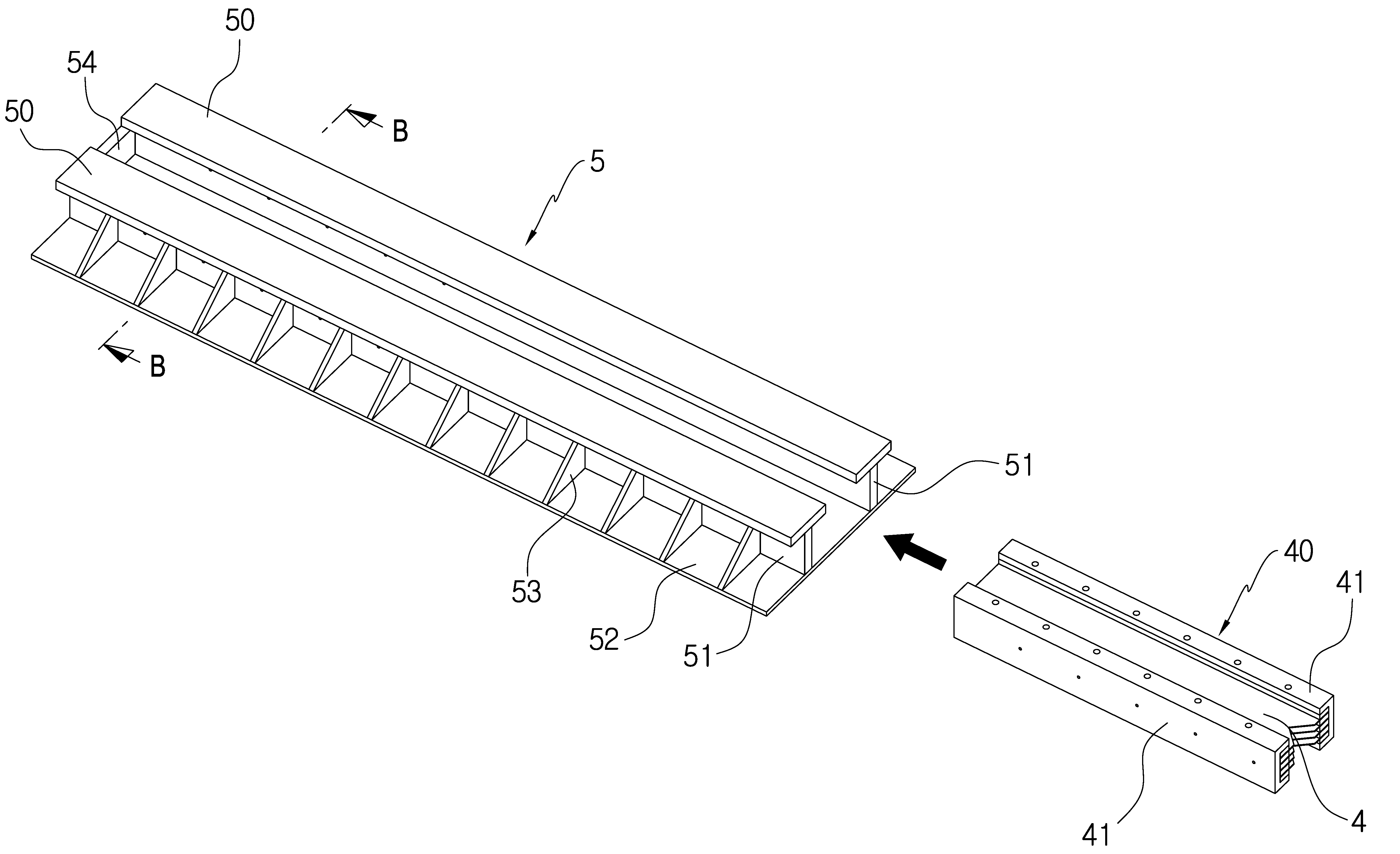
도 3에는 도 2에 도시된 본 발명의 제1실시예에 구비되는 슬라이딩 레일 조립체(5)를 기초부재(2)의 콘크리트 부재(20)에 매립되지 않은 상태로 온전하게 보여주는 개략적인 사시도가 도시되어 있으며, 도 4 및 도 5에는 각각 도 3에 도시된 슬라이딩 레일 조립체(5)에서 충돌에너지 흡수부재 유닛("EAM 유닛")(40)이 조립 장착되는 상태를 각각 바라보는 방향을 달리하여 보여주는 개략적인 분해 사시도가 도시되어 있다. 그리고 도 6에는 EAM 유닛(40)이 아직 삽입 장착되지 않은 위치에 해당하는 도 4의 선 B-B 위치에서의 슬라이딩 레일 조립체(5)에 대한 개략적인 후방으로의 단면도가 도시되어 있다. 3 is a schematic perspective view showing the sliding
도 3 내지 도 6에 예시된 것처럼, 슬라이딩 레일 조립체(5)는, 슬라이딩 지지부재(50), 연직지지부재(51) 및 바닥부재(52)를 포함하여 구성된다. 구체적으로 슬라이딩 지지부재(50)는 종방향으로 길게 연장된 부재로 이루어지며, 2개가 한 쌍을 이루어서 횡방향의 간격을 두고 동일한 평면상에서 나란하게 배치된다. 도면에 예시된 것처럼 슬라이딩 지지부재(50)는 평평한 판재로 이루어질 수 있다. 이러한 슬라이딩 지지부재(50)는 후술하는 것처럼 지주 본체(1)의 하단에 구비되는 베이스 플레이트(10)를 지지함과 동시에 베이스 플레이트(10)가 후방으로 슬라이딩할 수 있도록 하는 슬라이딩 레일(sliding rail)로서 기능한다. 3 to 6, the sliding
연직지지부재(51)는 슬라이딩 지지부재(50)가 바닥부재(52)로부터 연직간격을 두고 위치하도록 지지하는 부재로서, 종방향으로 길게 연장된 부재로 이루어져 있고 2개가 한 쌍을 이루어서 횡방향의 간격을 두고 나란하게 배치되어 연직하게 세워진 상태로 바닥부재(52)의 상면에 일체로 설치된다. 2개의 연직지지부재(51)는 2개의 슬라이딩 지지부재(50)를 각각 지지하며, 이를 위하여 연직지지부재(51)의 상단은 슬라이딩 지지부재(50)의 하면과 일체 결합되어 있는데, 도면에 예시된 실시예에서 2개의 연직지지부재(51) 사이의 횡방향 간격이 2개의 슬라이딩 지지부재(50) 사이의 횡방향 간격보다 더 크다. 각각의 연직지지부재(51)는 판부재로 이루어질 수 있다. 2개의 연직지지부재(51) 사이의 공간은, 위에서 언급한 특허출원 제10-2016-0006316호에서의 가이드 통로(Guide Trough)(3)에 해당한다. 본 발명에서는 2개의 연직지지부재(51) 사이의 공간에 의해 가이드 통로(3)가 형성되며, 이러한 2개의 연직지지부재(51) 사이의 간격은 후술하는 것처럼 EAM(4)과 충돌하게 되는 타격부재(11)의 형상을 다양한 형태로 변형할 수 있는 충분한 공간을 제공하게 된다. 즉, 2개의 연직지지부재(51) 사이의 공간에 의해 가이드 통로(3)가 형성되기 때문에 타격부재(11)의 형상을 다양하게 변화시킬 수 있게 되고, 그에 따라 후술하는 것처럼 EAM(4)를 손쉽게 교체할 수 있는 구성을 용이하게 만들 수 있게 되는 것이다. The
바닥부재(52)는 연직지지부재(51)의 하단에 결합 배치되는 부재로서 평평한 판부재로 이루어질 수 있으며, 필요에 따라서는 바닥부재(52)와 연직지지부재(51)의 외측면 사이에는 보강리브(53)가 설치될 수 있고, 이러한 보강리브(53)는 종방향으로 복수개가 간격을 두고 구비될 수 있다. The
후술하는 것처럼 연직지지부재(51) 사이의 횡방향 간격에는 EAM 유닛(40)이 삽입 배치되는데, EAM 유닛(40) 자체가 후방으로 밀려나는 것을 방지하기 위하여, 슬라이딩 레일 조립체(5)에서 후방단부에는 EAM 유닛(40)의 후방 이동을 저지하기 위한 마감부재(54)가 구비된다. 도면에 도시된 것처럼 마감부재(54)는 판부재로 이루어져서 연직지지부재(51) 사이의 횡방향 간격을 완전히 막도록 설치될 수도 있지만, EAM 유닛(40)의 EAM 고정부재(41)가 후방으로 이동하는 것만 저지할 수 있는 형태로 연직지지부재(51) 사이의 횡방향 간격을 부분적으로 가로막도록 설치될 수도 있다. The
EAM 유닛(40)은 EAM(4)이 구비되어 있는 부재로서, 전술하였듯이 연직지지부재(51) 사이의 횡방향 간격에 삽입 배치된다. 도 7의 (a) 및 (b)에는 각각 도 2 내지 도 6에 도시된 제1실시예에 구비된 EAM 유닛(40)을 바라보는 방향을 달리하여 보여주는 개략적인 사시도가 도시되어 있다. 도면에 도시된 것처럼, EAM 유닛(40)에는 한 쌍의 EAM 고정부재(41)가 구비되어 있는데, EAM 고정부재(41)는 종방향의 단면 형상이 ㄷ형태를 가지면서 종방향으로 길게 연장되어 있는 부재로서, 이러한 EAM 고정부재(41)의 한 쌍이 횡방향으로 간격을 두고 ㄷ자의 오목한 부분이 서로 마주보도록 거울대칭 관계로 배치되어 있다. 한 쌍의 EAM 고정부재(41) 사이에는 EAM(4)이 배치되어 있다. 도 8에는 EAM 유닛(40)에 대한 종방향 단면구성을 보여주는 도 7의 선 C-C에 따른 개략적인 종방향 단면도가 도시되어 있는데, 도 2 내지 도 8에 도시된 제1실시예에서, EAM(4)은 종방향으로 연장된 판형상 부재로 이루어져서 복수개가 연직하게 적층되고 횡방향 양단이 EAM 고정부재(41)의 ㄷ자 형 오목한 부분에 위치한 상태로 한 쌍의 EAM 고정부재(41) 사이의 횡방향 간격에 수평하게 배치되어 있는 구성을 가진다. 판부재로 이루어진 복수개의 EAM(4)이 연직하게 적층됨에 있어서, 도면에 도시된 것처럼 EAM(4) 사이에는 간격재(44)를 배치하여 복수개의 EAM(4)이 서로 연직 간격을 두고 적층되도록 할 수 있다. 이 때, 간격재(44)는 EAM(4)의 횡방향 양단에 위치하여 EAM 고정부재(41)의 ㄷ자의 오목한 부분 내에 위치할 수 있다. The
이와 같이, EAM 유닛(40)은 EAM 고정부재(41), 간격재(44) 및 EAM(4)의 조립 구조를 가지고 있으므로, EAM(4)이 파손되었을 때, EAM(4)과 간격재(44)를 EAM 고정부재(41)로부터 빼낸 후, 손상된 EAM을 새것으로 교체하여 다시 간격재(44)와 함께 EAM 고정부재(41)에 조립할 수 있다. 따라서 손상된 EAM(4)을 매우 용이하게 교체하여 EAM 유닛(40)을 다시 사용가능한 상태로 만들 수 있게 된다. As described above, the
또한 이와 같은 판형의 EAM(4)을 이용하는 구성에 의하면, 다양한 형태의 차량 충돌조건에 맞추어서, 판형(板形)으로 이루어진 EAM(4)의 두께, 재질, 적층 개수 등을 변경하여 최적의 충돌감쇄 효과를 발휘할 수 있도록 할 수 있게 되는 장점이 발휘된다. 즉, 가이드 통로에서의 이격거리(L)를 변화시키지 않더라도 다양한 형태의 차량 충돌조건에 맞추어서 최적의 EAM(4) 설치가 가능하게 되는 것이다. Further, according to the configuration using the plate-shaped
판형의 EAM(4)과 간격재(44)를 EAM 고정부재(41)에 조립 설치함에 있어서, 도면에 도시된 것처럼 볼트 등의 관통고정부재(46)를 EAM 고정부재(41), 간격재(44) 및 EAM(4)의 횡방향 양측에서 연직하게 관통시킴으로써, EAM 고정부재(41), 간격재(44) 및 EAM(4)를 일체화시킬 수도 있다. 그리고 도면에 도시된 것처럼 판형으로 이루어진 EAM(4)의 전방단부 즉, EAM(4)에 해당하는 판형상 부재의 전방단부에는, 후술하는 타격부재(11)의 화살촉 형태의 후방 형상에 맞추어서 삼각형 형태로 오목하게 파인 절취부를 형성해두는 것도 바람직하다. 그러나 이러한 절취부는 생략이 가능하다. 판형의 EAM(4)은 다양한 재질로 이루어질 수 있는데, 섬유판, 합성수지판 등 파쇄나 변형에 의해 에너지를 흡수할 수 있는 재질이라면 어떠한 것이라도 판형의 EAM(4)으로 이용할 수 있다. When the plate-
위와 같은 구성을 가지는 EAM 유닛(40)은 연직지지부재(51) 사이의 횡방향 간격에 삽입 배치되는데, 도 2 내지 도 6에 도시된 제1실시예의 경우, 슬라이딩 레일 조립체(5)의 전방단부에서부터 EAM 유닛(40)이 후방을 향하여 연직지지부재(51) 사이로 삽입된다. 이렇게 연직지지부재(51) 사이의 횡방향 간격에 삽입된 EAM 유닛(40)은, 슬라이딩 레일 조립체(5)의 후방에 위치하게 되는데, 연직지지부재(51)의 후방단부가 마감부재(54)에 닿도록 위치하는 것도 바람직하다. 2 to 6, the
도 9에는 슬라이딩 레일 조립체(5)에 EAM 유닛(40)이 삽입 배치된 상태를 보여주는 도 3의 선 A-A 위치에서의 슬라이딩 레일 조립체(5)에 대한 개략적인 후방으로의 단면도가 도시되어 있다. 본 발명에서는 EAM 유닛(40)이 가이드 통로에 삽입 배치된 상태에서는 EAM 유닛(40)의 위쪽 일부가 슬라이딩 지지부재(50)로 덮여져서 EAM 유닛(40)이 연직 상방으로 들어 올려지지 않게 된다. 구체적으로 도면에 도시된 본 발명에 따른 슬라이딩 레일 조립체(5)의 실시예에서는, 앞서 언급한 것처럼 연직지지부재(51) 사이의 횡방향 간격이 슬라이딩 지지부재(50) 사이의 횡방향 간격보다 더 크므로, EAM 유닛(40)이 연직지지부재(51) 사이의 횡방향 간격으로 만들어진 가이드 통로에 삽입 배치된 상태에서는 EAM 유닛(40)의 횡방향 가장자리가 슬라이딩 지지부재(50)에 의해 덮여 있게 되고, 그에 따라 EAM 유닛(40)이 연직 상방으로 들어 올려지는 것이 원천적으로 방지되는 것이다. 따라서 후술하는 것처럼 차량의 충격이 EAM 유닛(40)에 가해질 때, EAM 유닛(40)이 연직 상방으로 들어 올려지지 않은 상태에서 EAM(4)의 파쇄 내지 변형에 의한 충격 감소 및 지주본체(1)의 정지 작용이 원활하게 이루지게 되는 효과가 발휘된다. 9 is a schematic rear sectional view of the sliding
도 10 내지 도 13에는 본 발명의 제2실시예에 따른 감충지주에 구비되는 슬라이딩 레일 조립체(5)가 도시되어 있는데, 구체적으로 도 10에는 본 발명의 제2실시예에 따른 감충지주에 구비되는 슬라이딩 레일 조립체(5)에 대한 개략적인 조립 사시도가 도시되어 있으며, 도 11에는 도 10의 제2실시예에 따른 슬라이딩 레일 조립체(5)에서 EAM 유닛(40)이 삽입되어 조립 결합되는 상태를 보여주는 개략적인 분해 사시도가 도시되어 있다. 도 12에는 도 11의 선 D-D에 따른 개략적인 후방으로의 종방향 단면도가 도시되어 있으며, 도 13에는 도 11에 도시된 상태에 후속하여 EAM 유닛(40)이 연직지지부재(51) 사이의 횡방향 간격으로 삽입되는 상태를 보여주는 개략적인 사시도가 도시되어 있다. 10 to 13 show a sliding
도 10 내지 도 13에 도시된 제2실시예에서의 슬라이딩 레일 조립체(5)가 앞서 설명한 도 2 내지 도 9의 제1실시예와 상이한 구성은, 슬라이딩 레일 조립체(5)의 전방에서 슬라이딩 지지부재(50) 사이의 횡방향 간격에 EAM 유닛(40)이 연직방향으로부터 하강하여 삽입될 수 있는 확폭부가 형성되어 있다는 점이다. 즉, 슬라이딩 레일 조립체(5)의 전방에서부터 종방향으로 소정 길이의 구간에서 한 쌍의 슬라이딩 지지부재(50)가 절취되어 있으며, 따라서 슬라이딩 지지부재(50) 사이의 횡방향 간격에는 확폭부가 소정 길이의 구간에 형성되어 있다. The sliding
따라서 도 11 및 도 12에 도시된 것처럼 확폭부를 통해서 EAM 유닛(40)을 연직방향으로 하강시켜서 연직지지부재(51) 사이의 횡방향 간격에 위치시킨 후, 도 13에 도시된 것처럼 EAM 유닛(40)을 후방으로(도 13의 화살표 방향으로) 밀어서 도 10에 도시된 것처럼 EAM 유닛(40)이 연직 상방으로 들어 올려질 수 없는 위치까지 삽입 배치하게 된다. 이러한 도 10 내지 도 13에 도시된 제2실시예의 경우, EAM 유닛(40)이 연직방향으로 하강하여 슬라이딩 레일 조립체(5)에 조립되므로, 슬라이딩 레일 조립체(5)의 전방에 여유 공간이 부족한 경우에도 용이하게 EAM 유닛(40)을 조립 설치할 수 있게 되는 장점이 있다. Therefore, after the
위에서 설명한 제1 및 제2실시예에서 EAM 유닛(40)에 구비된 EAM(4)은 판형의 부재로 이루어졌으나, EAM(4)은 후술하는 것처럼 복수개의 통형상(파이프 형상)의 부재로 이루어질 수도 있다. 도 14에는 본 발명의 제3실시예에 구비되는 EAM 유닛(40)의 개략적인 조립 사시도가 도시되어 있으며, 도 15에는 도 14에 도시된 EAM 유닛(40)의 개략적인 분해 사시도가 도시되어 있다. In the first and second embodiments described above, the
도 14 및 도 15에 도시된 EAM 유닛(40)은, 앞서 설명한 제1 및 제2실시예와 마찬가지로 종방향의 단면 형상이 ㄷ형태를 가지면서 종방향으로 길게 연장되어 있는 부재로 이루어진 한 쌍의 EAM 고정부재(41)와, 그 사이에 배치되는 EAM(4)으로 이루어지는데, 도 14 및 도 15에 EAM(4)은, 횡방향으로 연장된 상태의 통형상 부재가 종방향으로 복수개 배치되어 있는 구성을 가진다. 즉, 강관 등과 같이 파이프 형태로 이루어진 통형상 부재의 연장된 양단이 EAM 고정부재(41)의 ㄷ자 형 오목한 부분에 위치하면서 종방향으로는 복수개가 배치되어 있는 형태로 EAM(4)이 구성되어 있는 것이다. 이와 같은 구성에서는 통형상 부재의 EAM(4)가 이탈되지 않고 안정적으로 그리고 간편한 작업을 통해서 설치된다. 특히, 이러한 구성에서는 EAM(4)을 이루는 통형상 부재의 설치개수를 용이하게 변화시킬 수 있고, 필요에 따라서는 통형상 부재의 강성(두께, 재질 등)을 필요에 맞게 선정하는 것이 용이하므로 차량 충격흡수를 위한 최적의 성능이 발휘될 수 있는 충격에너지 흡수능력의 EAM(4)을 설치할 수 있게 되는 장점이 있다. The
후술하는 것처럼 베이스 플레이트(10)에 구비된 타격부재(11)가 EAM(4)을 이루는 통형상 부재를 순차적으로 변형 및 파쇄하면서 충격흡수작동이 이루어지게 된다. 특히, 이와 같이 EAM(4)이 통형상 부재로 이루어진 경우, 충격흡수작용이 진행된 후 파손된 통형상 부재만을 새 것으로 교체함으로써 EAM 유닛(40)을 용이하게 다시 사용할 수 있게 되는 장점이 있다. 즉, 위의 실시예의 경우, 차량 충돌에 의해 지주본체가 후방으로 이동한 거리 내에서만 통형상 부재가 파손될 것이므로, 파손된 통형상 부재만을 제거하고 새로운 통형상 부재를 설치함으로써 쉽게 EAM 유닛(40)을 재사용할 수 있게 되는 것이다. The shock absorbing operation is performed while the striking
도 16 및 도 17에는 각각 도 14에 도시된 EAM 유닛(40)이 삽입되어 조립 결합되는 상태를 각각 바라보는 방향을 달리하여 보여주는 개략적인 분해 사시도가 도시되어 있으며, 도 18에는 이에 후속하여 EAM 유닛(40)의 삽입 장착이 완료된 상태의 슬라이딩 레일 조립체(5)를 보여주는 개략적인 사시도가 도시되어 있다. 도 14에 도시된 EAM 유닛(40)의 경우에도 앞서 설명한 제1 및 제2실시예와 마찬가지로 연직지지부재(51) 사이의 횡방향 간격에 삽입 배치된다. 즉, 도 16 내지 도 18에 도시된 것처럼 슬라이딩 레일 조립체(5)의 전방단부에서부터 EAM 유닛(40)이 후방을 향하여 연직지지부재(51) 사이로 삽입되어 슬라이딩 레일 조립체(5)의 후방에 위치하는 형태로 조립 설치될 수 있는 것이다. Figs. 16 and 17 are schematic exploded perspective views showing different directions in which the
한편, 도 14에 도시된 것처럼 EAM(4)이 통형상 부재로 이루어진 EAM 유닛(40)의 경우에도, 앞서 살펴본 제2실시예와 마찬가지로 연직하강 방식으로 슬라이딩 레일 조립체(5)에 조립 설치될 수 있다. 도 19 및 도 20에는 각각 EAM(4)이 통형상 부재로 이루어진 EAM 유닛(40)이 연직하강하여 조립되는 본 발명의 제4실시예에 따른 슬라이딩 레일 조립체(5)의 조립 과정을 순차적으로 보여주는 개략적인 사시도가 도시되어 있으며, 도 21에는 이에 후속하여 조립이 완료된 본 발명의 제4실시예에 따른 슬라이딩 레일 조립체(5)의 개략적인 사시도가 도시되어 있다. 14, in the case of the
EAM(4)이 통형상 부재로 이루어진 EAM 유닛(40)의 경우에도, 도 19 내지 도 21에 도시된 것처럼, 슬라이딩 레일 조립체(5)의 슬라이딩 지지부재(50) 사이에 형성된 확폭부에 연직방향으로 하강시켜서 연직지지부재(51) 사이에 위치시킨 후, EAM 유닛(40)을 후방으로 밀어서 EAM 유닛(40)이 연직 상방으로 들어 올려질 수 없는 위치까지 삽입 배치함으로써 EAM 유닛(40)을 슬라이딩 레일 조립체(5)에 조립 설치할 수 있는 것이다. 19 to 21, even in the case of the
EAM 유닛(40)을 위와 같은 방식으로 슬라이딩 레일 조립체(5)에 조립하는 과정을 역(逆)으로 수행함으로써 EAM 유닛(40)을 쉽게 슬라이딩 레일 조립체(5)로부터 제거할 수도 있다. 즉, EAM 유닛(40)을 전방으로 당겨서 연직지지부재(51) 사이로부터 빼내므로서 슬라이딩 레일 조립체(5)로부터 매우 쉽게 분리할 수 있는 것이다. 확폭부가 형성된 경우에는 EAM 유닛(40)을 확폭부까지 전방으로 당긴 후, 확폭부에서 연직 상방으로 EAM 유닛(40)을 들어 올림으로써 슬라이딩 레일 조립체(5)로부터 EAM 유닛(40)을 매우 쉽게 분리할 수 있게 된다. The
아래에서는 위와 같은 제1 내지 제4실시예에 따른 슬라이딩 레일 조립체(5)를 구비한 기초부재(2)와 지주본체(1)의 조립 구성 및 차량 충돌시의 충격흡수 메커니즘에 대해 설명한다. 앞서 언급한 것처럼, 슬라이딩 레일 조립체(5)가 콘크리트 부재(20)에 매립되어 일체화된 상태로 기초부재(2)가 제작되는데, 현장에서 또는 공장에서 거푸집 내에 슬라이딩 레일 조립체(5)를 배치하고, 슬라이딩 지지부재(50)와 연직지지부재(51)의 상부가 노출될 수 있는 높이까지 콘크리트를 타설하여 기초부재(2)를 제작할 수 있다. 기초부재(2)에는 지주 본체(1)를 조립하여 설치하게 된다. The following describes the assembling structure of the
도 22에는 본 발명에 따른 감충지주에 구비되는 지주 본체(1)를 아래에서 위로 올려다본 형태로 보여주는 개략적인 사시도가 도시되어 있는데, 지주 본체(1)는 도로표지판 등이 설치되는 기둥 형태의 부재로서, 그 하단에는 베이스 플레이트(10)가 일체로 구비되어 있다. 베이스 플레이트(10)의 횡방향 양측에는 슬라이딩 레일 조립체(5)의 슬라이딩 지지부재(50)가 끼워질 수 있는 간격을 가지도록 ㄷ자 형태로 슬라이딩 지지부재(50)의 횡방향 가장자리를 감싸는 결합부(12)가 형성되어 있다. FIG. 22 is a schematic perspective view of a
베이스 플레이트(10)의 하면에는 타격부재(11)가 하향 돌출되도록 일체 구비되어 있다. 도 22에 도시된 베이스 플레이트(10)는 앞서 설명한 제1 및 제2실시예의 EAM 유닛 즉, 판형상의 EAM(4)을 구비한 EAM 유닛(40)을 사용할 때 적합한 것으로서, 타격부재(11)가 판형상의 EAM(4)을 찢어서 파쇄할 수 있도록 연직하게 세워져서 종방향으로 연장된 판형상의 부재로 이루어져 있으며, 타격부재(11)의 후방 단부는 화살촉 형상으로 이루어질 수도 있다. On the lower surface of the
도 23에는 본 발명의 제1실시예에 따른 기초부재(2)에 지주 본체(1)를 조립하는 상태를 보여주는 개략적인 분해 사시도가 도시되어 있다. 도 23의 상태에 후속하여 기초부재(2)와 지주 본체(1)의 조립 완료를 통해서 본 발명의 감충지주(100)가 완성된 상태를 보여주는 개략적인 사시도는 도 2에 도시되어 있다. 도면에 도시된 것처럼, 슬라이딩 레일 조립체(5)가 콘크리트 부재(20)에 매립되어 일체화된 형태로 기초부재(2)가 제작되는데, 이 때, 슬라이딩 레일 조립체(5)의 슬라이딩 지지부재(50)는 콘크리트 부재(20)의 상면에서부터 소정 연직 간격을 두고 위치하게 된다. 23 is a schematic exploded perspective view showing a state in which the column
이와 같은 구성의 기초부재(2)에, 베이스 플레이트(10)와 타격부재(11)를 가지는 지주 본체(1)를 조립 설치하게 되는데, 이 때 베이스 플레이트(10)의 횡방향 양측에 구비된 결합부(12)의 ㄷ자 형태의 간격에, 슬라이딩 레일 조립체(5)의 슬라이딩 지지부재(50)가 기초부재(2)의 전방 측면에서부터 끼워지게 되며, 그에 따라 베이스 플레이트(10)의 하면은 슬라이딩 지지부재(50)의 상면에 밀착 지지된 상태가 되어, 지주 본체(1)가 세워져 설치된다. 이러한 상태에서 타격부재(11)는 슬라이딩 레일 조립체(5)에 구비된 연직지지부재(51) 사이의 가이드 통로 내에 위치하게 된다. The
본 발명에서는 위와 같이 지주 본체(1)의 하단에 구비된 베이스 플레이트(10)가 슬라이딩 지지부재(50)의 가장자리를 감싼 상태에 있게 되므로, 풍하중 등이 지주 본체(1)에 작용하여 휨모멘트 등으로 인하여 지주 본체(1)를 연직 상향으로 뽑아내려는 인발력이 작용하더라도 결합부(12)와 슬라이딩 지지부재(50)간의 위와 같은 결합에 의해 강한 인발저항력이 작용하게 되며 그에 따라 지주 본체(1)는 풍하중 등으로 인한 전도에 대해 강한 저항력을 발휘하게 되어 매우 우수한 안정성을 가지게 된다. In the present invention, since the
도 24에는 본 발명에 따른 감충지주에서 구비되는 지주 본체(1)의 또다른 실시예를 아래에서 위로 올려다본 형태로 보여주는 개략적인 사시도가 도시되어 있는데, 도 24에 도시된 지주 본체(1)는 앞서 설명한 제3 및 제4실시예의 EAM 유닛 즉, 통형상의 부재로 이루어진 EAM(4)을 구비한 EAM 유닛(40)을 사용할 때 적합한 것으로서, 타격부재(11)가 통형상의 EAM(4)을 파쇄할 수 있도록 연직하게 세워져서 종방향으로 연장된 판형상의 부재로 이루어져 있으며, 타격부재(11)의 후방 단부는 넓은 면적으로 통형상의 EAM(4)에 접촉할 수 있도록 면적이 증가된 형상으로 이루어질 수도 있다. 이를 위해서 도면에 도시된 실시예의 경우 타격부재(11)의 후방 단부에는 횡방향으로 연장된 평평한 타격판(110)이 구비되어 있다. 24 is a perspective view schematically showing another embodiment of the
도 25에는 본 발명의 제3실시예에 따른 기초부재(2)에 도 24에 도시된 지주 본체(1)를 조립하는 상태를 보여주는 개략적인 분해 사시도가 도시되어 있으며, 도 26에는 도 26의 상태에 후속하여 기초부재(2)와 지주 본체(1)의 조립 완료를 통해서 본 발명의 감충지주(100)가 완성된 상태를 보여주는 개략적인 사시도가 도시되어 있다. 도 24 내지 도 26에 도시된 감충지주(100)의 경우도, 앞서 도 22 내지 도 23을 참조하여 설명한 실시예와 마찬가지로 베이스 플레이트(10)의 결합부(12)에 형성된 ㄷ자 형태의 간격에 슬라이딩 지지부재(50)가 끼워지며, 그에 따라 타격부재(11)는 슬라이딩 레일 조립체(5)에 구비된 연직지지부재(51) 사이의 공간 즉, 가이드 통로에 위치하게 된다. Fig. 25 is a schematic exploded perspective view showing a state in which the
기초부재(2)와 지주 본체(1)의 조립이 완료된 감충지주(100)의 지주 본체(1)에 차량이 충돌하게 되면 차량과 지주 본체(1), 그리고 베이스 플레이트(10)는 후방으로 이동하기 시작한다. 슬라이딩 레일 조립체(5)의 슬라이딩 지지부재(50)는 후방으로 길게 연장되어 있으므로, 베이스 플레이트(10)는 그 하면이 슬라이딩 지지부재(50)의 상면에 접한 상태로 후방으로 밀려가게 된다. When the vehicle collides with the column
본 발명의 슬라이딩 레일 조립체(5)에서는, 차량 충돌전 지주 본체(1)가 세워져 있는 위치와 EAM(4)이 채워져 있기 시작하는 위치 사이에 이격거리(L)만큼의 빈 공간이 존재하는데, 차량 충돌 후 차량과 지주 본체(1)가 이격거리(L)의 구간을 함께 이동한 후, 타격부재(11)가 EAM(4)에 닿으면서 EAM(4)을 충격하게 된다. 도 27에는 제1실시예에서 도 2의 상태에 후속하여 타격부재(11)가 EAM(4)을 충격하기 시작하는 상태를 보여주는 개략적인 사시도가 도시되어 있으며, 도 28에는 제3실시예에서 도 26에 후속하여 타격부재(11)가 EAM(4)을 충격하기 시작하는 상태를 보여주는 개략적인 사시도가 도시되어 있다. 이와 같이 차량이 충돌하였을 초기에는 이격거리(L) 구간에서는 지주 본체 자체의 관성을 이용하여 충돌 차량의 속도를 저감시키고, 이후에는 EAM(4)의 충격흡수능력을 이용하여 충돌에너지 및 운동에너지를 효율적으로 소산시켜서 차량을 정지시킴으로써 탑승자의 안전을 확보하게 된다. In the sliding
판형상의 EAM(4)을 구비한 제1 및 제2실시예의 경우, 타격부재(11)가 EAM(4)에 닿으면서 판형상의 EAM(4)을 찢는 형태로 파쇄하게 되는데, 이 과정에서 차량 충돌에너지가 소산되어 지주 본체(1)와 차량의 후방 이동속도가 감소되며, 종국에는 지주 본체(1)와 차량이 정지하게 된다. 이와 같이 타격부재(11)가 EAM(4)을 찢으면서 파쇄하여 충돌에너지를 소산시키기 때문에, EAM(4)가 파쇄된 상태에서는 EAM(4)가 찢어져서 만들어진 공간을 통해서 지주 본체(1)가 후방으로 원활하게 이동할 수 있게 되고, 이와 같이 지주 본체(1)가 찢어진 EAM(4) 사이로 후방 이동하는 과정에서 추가적인 충돌에너지의 소산이 일어나는 장점이 발휘된다. In the case of the first and second embodiments having the plate-shaped
통형상의 EAM(4)을 구비한 제3 및 제4실시예의 경우, 타격부재(11)가 EAM(4)에 닿으면서 통형상의 EAM(4)을 순차적으로 변형 및 파쇄시키면서 차량 충돌에너지의 소산이 일어나고 그에 따라 지주 본체(1)와 차량의 후방 이동속도를 감소시켜서 그 이동을 정지시키게 된다. 통형상의 EAM(4)의 경우에도, 타격부재(11)의 충돌에 의해 통형상의 EAM(4)이 절단될 수 있으며, 이 경우에는 판형의 EAM(4)가 찢어질 때와 마찬가지로 EAM(4)이 절단되어 만들어진 공간을 통해서 지주 본체(1)가 후방으로 원활하게 이동할 수 있게 되어 지주 본체(1)의 계속되는 후방 이동에 의한 추가적인 충돌에너지 소산의 장점을 가지게 된다. In the third and fourth embodiments having the
본 발명에서는 앞서 설명한 것처럼 EAM 유닛(40)을 슬라이딩 레일 조립체(5)에 용이하게 조립할 수 있으며, 더 나아가 쉽게 분리할 수도 있다. 따라서 위와 같은 차량 충돌로 인한 충격을 충분히 흡수한 후에는, 앞서 설명한 방식으로 EAM 유닛(40)을 전방으로 당겨서 연직지지부재(51) 사이의 가이드 통로로부터 완전히 빼내거나 또는 EAM 유닛(40)을 확폭부까지 전방으로 당긴 후 연직 상방으로 EAM 유닛(40)을 들어 올림으로써 슬라이딩 레일 조립체(5)로부터 EAM 유닛(40)을 분리시킨다. 이렇게 분리된 EAM 유닛(40)에서 손상된 EAM(4)을 새것으로 교체한 후, 다시 EAM 유닛(40)을 슬라이딩 레일 조립체(5)에 재조립한 후, 새로운 지주 본체(1)를 다시 설치하는 형태로 감충지주를 용이하고 신속하게 재사용할 수 있는 상태로 복원할 수 있게 된다. 이와 같이 본 발명에 의하면, 손상된 EAM을 새것으로 용이하고 신속하게 교체하여 사용할 수 있게 되므로, 차량 충돌 사고가 발생한 후에도, 빠르게 감충지주를 재설치하여 안전한 도로환경을 지속적으로 유지할 수 있게 되는 것이다. In the present invention, as described above, the
1: 지주 본체
2: 기초부재
3: 가이드 통로
4: EAM
5: 슬라이딩 레일 조립체
10: 베이스 플레이트
11: 타격부재
40: EAM 유닛
100: 감충지주1: holding body
2: base member
3: guide passage
4: EAM
5: Sliding rail assembly
10: Base plate
11: striking member
40: EAM unit
100: insect pillars
Claims (8)
바닥부재(52); 종방향으로 연장되어 있으며 2개가 횡방향 간격을 두고 나란하게 배치되어 지주 본체(1)의 하단에 구비된 베이스 플레이트(10)가 슬라이딩될 수 있도록 지지하는 슬라이딩 지지부재(50); 및 슬라이딩 지지부재(50)가 바닥부재(52)로부터 연직간격을 두고 위치하도록 각각의 슬라이딩 지지부재(50)를 지지하는 한 쌍의 연직지지부재(51)를 포함하며;
연직지지부재(51) 사이의 횡방향 간격에 의한 가이드 통로에는, 충돌에 의해 변형되어 에너지를 흡수하는 EAM(4)이 구비되어 있는 EAM 유닛(40)이 교체 가능하도록 종방향으로 끼워져 배치되어 있되, EAM 유닛(40)이 가이드 통로에 삽입 배치된 상태에서 EAM 유닛(40)의 위쪽 일부가 슬라이딩 지지부재(50)로 덮여져서 EAM 유닛(40)이 연직 상방으로 들어 올려지지 않으며;
기초부재(2)의 콘크리트 부재(20)에 슬라이딩 레일 조립체(5)가 매립 설치된 상태에서 베이스 플레이트(10)가 슬라이딩 지지부재(50)의 횡방향 양측을 감싸는 형태로 결합되고, 차량 충돌에 의해 지주 본체(1)와 베이스 플레이트(10)가 이동하여 베이스 플레이트(10)의 하부에 돌출 구비된 타격부재(11)가 EAM(4)과 충돌하게 되면 EAM(4)이 파손되면서 차량의 충돌로 인한 충돌에너지의 흡수 및 소산 작동이 일어나며, 차량 충돌 종료 후에는 EAM 유닛(40)을 분리하여 EAM(4)을 교체한 후 EAM 유닛(40)이 다시 상기 가이드 통로에 삽입 배치되는 구성을 가지는데;
EAM 유닛(40)은, 종방향의 단면 형상이 ㄷ형태를 가지면서 종방향으로 길게 연장되어 있는 한 쌍의 EAM 고정부재(41)와, 상기 한 쌍의 EAM 고정부재(41) 사이에서 교체 가능한 상태로 배치되는 EAM(4)을 포함하여 구성되는 것을 특징으로 하는 감충지주를 위한 슬라이딩 레일 조립체.
A sliding rail assembly (5) embedded in a base member (2) composed of a concrete reinforcing member (20) so that a lower end of a supporting body (1) of a compulsory retarding insect pillars (100)
A bottom member 52; A sliding support member 50 extending in the longitudinal direction and arranged parallel to each other with two spaced apart from each other to support the base plate 10 provided at the lower end of the support body 1 so as to be slidable; And a pair of vertical support members (51) for supporting the respective sliding support members (50) so that the sliding support members (50) are vertically spaced from the bottom member (52);
The EAM unit 40 provided with the EAM 4 absorbing the energy and being deformed by the collision is fitted in the guide passage by the lateral spacing between the vertical support members 51 so as to be interchangeable in the longitudinal direction , The upper part of the EAM unit 40 is covered with the sliding support member 50 in a state where the EAM unit 40 is inserted into the guide passage, so that the EAM unit 40 is not lifted up vertically;
The base plate 10 is coupled in the form of wrapping both lateral sides of the sliding support member 50 in a state in which the sliding rail assembly 5 is embedded in the concrete member 20 of the base member 2, If the striking member 11 protruding from the lower portion of the base plate 10 collides with the EAM 4 after the main body 1 and the base plate 10 move and the EAM 4 collapses, And the EAM unit 40 is again inserted into the guide passage after the EAM unit 40 is detached and the EAM 4 is replaced after the end of the vehicle collision ;
The EAM unit 40 includes a pair of EAM fixing members 41 extending in the longitudinal direction with a cross-sectional shape in the longitudinal direction and a pair of EAM fixing members 41, Wherein the EAM (4) is arranged in a state that the EAM (4) is in a state of being positioned.
EAM 유닛(40)에 구비된 EAM(4)은, 종방향으로 연장된 판형 부재로 이루어져서 횡방향 양단이 EAM 고정부재(41)의 ㄷ자형 오목한 부분에 위치한 상태로 한 쌍의 EAM 고정부재(41) 사이의 횡방향 간격에 복수개가 수평하게 배치되어 연직하게 적층되어 있는 것을 특징으로 하는 감충지주를 위한 슬라이딩 레일 조립체.
The method according to claim 1,
The EAM 4 provided in the EAM unit 40 is constituted by a plate member extending in the longitudinal direction and a pair of EAM fixing members 41 Wherein a plurality of the sliding rail assemblies are vertically stacked horizontally at a lateral spacing between the sliding rails.
EAM 유닛(40)에 구비된 EAM(4)은, 횡방향으로 연장된 상태의 통형상 부재가, 횡방향 양단이 EAM 고정부재(41)의 ㄷ자형 오목한 부분에 위치하도록, 종방향으로 복수개 배치되어 있는 구성을 가지는 것을 특징으로 하는 감충지주를 위한 슬라이딩 레일 조립체.
The method according to claim 1,
The EAM 4 provided in the EAM unit 40 is configured such that the tubular members extending in the transverse direction are arranged in plural in the longitudinal direction so that the transversely opposite ends thereof are positioned in the C- Wherein the sliding rail assembly comprises:
슬라이딩 지지부재(50)는 평평한 판재로 이루어져 있으며;
연직지지부재(51)는 판부재로 이루어져서 연직지지부재(51)의 상단은 슬라이딩 지지부재(50)의 하면과 일체 결합되어 있고;
연직지지부재(51) 사이의 횡방향 간격은, 슬라이딩 지지부재(50) 사이의 횡방향 간격보다 더 커서, EAM 유닛(40)이 가이드 통로에 삽입 배치된 상태에서 EAM 유닛(40)의 횡방향 가장자리가 슬라이딩 지지부재(50)에 의해 덮여 있게 되며;
EAM 유닛(40)은, 슬라이딩 레일 조립체(5)의 전방단부에서부터 EAM 유닛(40)이 후방을 향하여 연직지지부재(51) 사이로 삽입되는 구성을 가지는 것을 특징으로 하는 감충지주를 위한 슬라이딩 레일 조립체.
The method of claim 1, 3, or 4,
The sliding support member 50 is made of a flat plate material;
The vertical support member 51 is formed of a plate member so that the upper end of the vertical support member 51 is integrally coupled with the lower surface of the sliding support member 50;
The lateral spacing between the vertical support members 51 is larger than the lateral spacing between the sliding support members 50 so that the EAM unit 40 is inserted in the guide passage in the lateral direction of the EAM unit 40 The edge is covered by the sliding support member 50;
Characterized in that the EAM unit (40) has a configuration in which the EAM unit (40) is inserted rearwardly from the front end of the sliding rail assembly (5) into the vertical support members (51).
슬라이딩 지지부재(50)는 평평한 판재로 이루어져 있으며;
연직지지부재(51)는 판부재로 이루어져서 연직지지부재(51)의 상단은 슬라이딩 지지부재(50)의 하면과 일체 결합되어 있고;
연직지지부재(51) 사이의 횡방향 간격은, 슬라이딩 지지부재(50) 사이의 횡방향 간격보다 더 커서, EAM 유닛(40)이 가이드 통로에 삽입 배치된 상태에서 EAM 유닛(40)의 횡방향 가장자리가 슬라이딩 지지부재(50)에 의해 덮여 있되;
슬라이딩 레일 조립체(5)의 전방에서 슬라이딩 지지부재(50) 사이의 횡방향 간격에는 EAM 유닛(40)이 연직방향으로부터 하강하여 삽입될 수 있는 확폭부가 형성되어 있어서, EAM 유닛(40)은 연직방향으로 하강되어 확폭부를 통해서 연직지지부재(51) 사이의 횡방향 간격에 위치된 후, 후방으로 밀어져서 가이드 통로에 삽입 배치되는 구성을 가지는 것을 특징으로 하는 감충지주를 위한 슬라이딩 레일 조립체.
The method of claim 1, 3, or 4,
The sliding support member 50 is made of a flat plate material;
The vertical support member 51 is formed of a plate member so that the upper end of the vertical support member 51 is integrally coupled with the lower surface of the sliding support member 50;
The lateral spacing between the vertical support members 51 is larger than the lateral spacing between the sliding support members 50 so that the EAM unit 40 is inserted in the guide passage in the lateral direction of the EAM unit 40 The edge being covered by the sliding support member (50);
The EAM unit 40 is formed with the widening portion in which the EAM unit 40 can be inserted downward from the vertical direction in the lateral gap between the sliding support members 50 at the front of the sliding rail assembly 5, Is positioned at a lateral distance between the vertical supporting members (51) through the wider portion, and then is pushed rearward and inserted into the guide passage.
기초부재(2)는 콘크리트 부재(20)로 이루어지는데, 상기 콘크리트 부재(20)에는 청구항 1에 의한 슬라이딩 레일 조립체(5)가 매립 설치되어 있되, 슬라이딩 레일 조립체(5)의 슬라이딩 지지부재(50)는 콘크리트 부재(20)의 상면에서부터 연직 간격을 두고 위치하게 되며;
베이스 플레이트(10)의 횡방향 양측에는 ㄷ자 형태로 슬라이딩 지지부재(50)의 횡방향 가장자리를 감싸는 결합부(12)가 형성되어 있어서, 상기 결합부(12)의 ㄷ자 형태의 간격에, 슬라이딩 레일 조립체(5)의 슬라이딩 지지부재(50)가 기초부재(2)의 전방 측면에서부터 끼워져서 결합되어, 지주 본체(1)가 기초부재(2)에 세워져 설치되고 타격부재(11)는 슬라이딩 레일 조립체(5)에 구비된 연직지지부재(51) 사이의 가이드 통로 내에 위치하게 되며;
차량이 지주 본체(1)에 충돌하게 되면 차량과 지주 본체(1)가 후방으로 이동하면서 1차적인 차량 속도의 감속이 일어난 후, 타격부재(11)가 EAM(4)을 충격하여 EAM(4)이 변형됨으로써, 차량의 충돌로 인한 충돌에너지의 흡수 및 소산을 통해서 2차적인 차량 속도의 감속이 일어나서 차량을 정지시키게 되는 구성을 가지는 것을 특징으로 하는 감충지주.A base plate 10 is provided at a lower end of a column main body 1 and a base plate 10 is provided at a lower end of the column main body 1. The base plate 10 is provided with a base member 2 and a column main body 1 vertically- The striking member 11 is provided on the lower surface thereof so as to protrude downward;
The slide rail assembly 5 according to claim 1 is embedded in the concrete member 20 so that the sliding support member 50 of the sliding rail assembly 5 Are positioned at regular intervals from the upper surface of the concrete member 20;
A pair of engaging portions 12 are formed on both lateral sides of the base plate 10 so as to surround the lateral edges of the sliding supporting member 50 in a C shape. The sliding support member 50 of the assembly 5 is fitted and engaged from the front side of the base member 2 so that the support main body 1 is erected on the base member 2 and the striking member 11 is fixed to the sliding rail assembly Is positioned in the guide passage between the vertical support members (51) provided on the support (5);
When the vehicle collides with the pillar main body 1, the striking member 11 impacts the EAM 4 and decelerates the EAM 4 Is deformed so that a deceleration of a secondary vehicle speed occurs through absorption and dissipation of impact energy due to collision of the vehicle, thereby stopping the vehicle.
지주는, 기초부재(2) 및 연직하게 세워져서 기초부재(2)에 설치되는 지주 본체(1)를 구비한 감충지주로 구성되어 있는데, 지주 본체(1)의 하단에는 베이스 플레이트(10)가 구비되어 있고, 베이스 플레이트(10)의 하면에는 타격부재(11)가 하향 돌출 구비되어 있으며;
기초부재(2)를 콘크리트 부재(20)로 제작할 때, 청구항 1에 의한 슬라이딩 레일 조립체(5)를 콘크리트 부재(20)에 매립 설치하되, 슬라이딩 레일 조립체(5)의 슬라이딩 지지부재(50)가 콘크리트 부재(20)의 상면에서부터 연직 간격을 두고 위치하게 만들며;
베이스 플레이트(10)의 횡방향 양측에는 ㄷ자 형태로 슬라이딩 지지부재(50)의 횡방향 가장자리를 감싸는 결합부(12)가 형성되어 있어서, 상기 결합부(12)의 ㄷ자 형태의 간격에, 슬라이딩 레일 조립체(5)의 슬라이딩 지지부재(50)가 기초부재(2)의 전방 측면에서부터 끼워져서 결합되도록 함으로써, 지주 본체(1)를 기초부재(2)에 세워져 설치하고 타격부재(11)가 슬라이딩 레일 조립체(5)에 구비된 연직지지부재(51) 사이의 가이드 통로 내에 위치하게 만들며;
차량이 지주 본체(1)에 충돌하게 되면 차량과 지주 본체(1)가 후방으로 이동하면서 차적인 차량 속도의 감속이 일어난 후, 타격부재(11)가 EAM(4)을 충격하여 EAM(4)이 변형되도록 함으로써, 차량의 충돌로 인한 충돌에너지의 흡수 및 소산을 통해서 2차적인 차량 속도의 감속이 일어나서 차량을 정지시키게 되는 것을 가지는 것을 특징으로 하는 감충지주를 이용한 차량 지주충돌시의 충격 감소방법. CLAIMS What is claimed is: 1. A method of reducing an impact occurring when a vehicle impacts on a support,
The support has a base member 2 and a support body 1 which is vertically erected and provided on the base member 2. A base plate 10 is provided at the lower end of the support body 1 And a striking member 11 protrudes downward from a bottom surface of the base plate 10;
The sliding rail assembly 5 of the sliding rail assembly 5 is embedded in the concrete member 20 when the base member 2 is made of the concrete member 20, To be vertically spaced from the upper surface of the concrete member 20;
A pair of engaging portions 12 are formed on both lateral sides of the base plate 10 so as to surround the lateral edges of the sliding supporting member 50 in a C shape. The support body 1 is installed upright on the base member 2 and the striking member 11 is mounted on the sliding rail 1 by mounting the sliding support member 50 of the assembly 5 on the front side of the base member 2, Is positioned within the guide path between the vertical support members (51) provided in the assembly (5);
When the vehicle collides with the pillar main body 1, the striking member 11 impacts the EAM 4 and the EAM 4 after decelerating the secondary vehicle speed while the vehicle and the main column body 1 move backward, And a second deceleration of the vehicle speed occurs through absorption and dissipation of the collision energy due to the collision of the vehicle, thereby stopping the vehicle. .
Priority Applications (1)
| Application Number | Priority Date | Filing Date | Title |
|---|---|---|---|
| KR1020170151635A KR101868552B1 (en) | 2017-11-14 | 2017-11-14 | Crashworthy Post, Sliding Rail Assembly therefor, and Method for Reducing Car Impact using such Crashworthy Post |
Applications Claiming Priority (1)
| Application Number | Priority Date | Filing Date | Title |
|---|---|---|---|
| KR1020170151635A KR101868552B1 (en) | 2017-11-14 | 2017-11-14 | Crashworthy Post, Sliding Rail Assembly therefor, and Method for Reducing Car Impact using such Crashworthy Post |
Publications (1)
| Publication Number | Publication Date |
|---|---|
| KR101868552B1 true KR101868552B1 (en) | 2018-06-19 |
Family
ID=62790705
Family Applications (1)
| Application Number | Title | Priority Date | Filing Date |
|---|---|---|---|
| KR1020170151635A Active KR101868552B1 (en) | 2017-11-14 | 2017-11-14 | Crashworthy Post, Sliding Rail Assembly therefor, and Method for Reducing Car Impact using such Crashworthy Post |
Country Status (1)
| Country | Link |
|---|---|
| KR (1) | KR101868552B1 (en) |
Cited By (3)
| Publication number | Priority date | Publication date | Assignee | Title |
|---|---|---|---|---|
| KR102009361B1 (en) | 2018-06-08 | 2019-08-12 | 한국건설기술연구원 | Crashworthy Post having Sliding Rail Assembly, and Method for Reducing Car Impact using such Crashworthy Post |
| KR102082861B1 (en) * | 2019-07-03 | 2020-03-02 | (주)미래로드셋 | Shock absorber in case of vehicle collision |
| KR102544513B1 (en) | 2022-11-18 | 2023-06-20 | 한국건설기술연구원 | Guard Rail for Impact Dispersion |
Citations (3)
| Publication number | Priority date | Publication date | Assignee | Title |
|---|---|---|---|---|
| KR100785661B1 (en) * | 2007-02-21 | 2007-12-14 | 고삼석 | Structure and installation method of fence post |
| KR100944566B1 (en) * | 2008-12-12 | 2010-03-03 | 강진구 | Impact attenuator for installation along road |
| KR20170077752A (en) | 2015-12-28 | 2017-07-06 | 한국건설기술연구원 | Crashworthy Post Utilizing Conservation of Linear Momentum and Energy Absorbing Module, and Method for Reducing Car Impact using such Crashworthy Post |
-
2017
- 2017-11-14 KR KR1020170151635A patent/KR101868552B1/en active Active
Patent Citations (3)
| Publication number | Priority date | Publication date | Assignee | Title |
|---|---|---|---|---|
| KR100785661B1 (en) * | 2007-02-21 | 2007-12-14 | 고삼석 | Structure and installation method of fence post |
| KR100944566B1 (en) * | 2008-12-12 | 2010-03-03 | 강진구 | Impact attenuator for installation along road |
| KR20170077752A (en) | 2015-12-28 | 2017-07-06 | 한국건설기술연구원 | Crashworthy Post Utilizing Conservation of Linear Momentum and Energy Absorbing Module, and Method for Reducing Car Impact using such Crashworthy Post |
Cited By (5)
| Publication number | Priority date | Publication date | Assignee | Title |
|---|---|---|---|---|
| KR102009361B1 (en) | 2018-06-08 | 2019-08-12 | 한국건설기술연구원 | Crashworthy Post having Sliding Rail Assembly, and Method for Reducing Car Impact using such Crashworthy Post |
| US11021843B2 (en) | 2018-12-18 | 2021-06-01 | Korea Institute Of Civil Engineering And Building Technology | Energy absorbing post having sliding rail assembly |
| KR102082861B1 (en) * | 2019-07-03 | 2020-03-02 | (주)미래로드셋 | Shock absorber in case of vehicle collision |
| KR102544513B1 (en) | 2022-11-18 | 2023-06-20 | 한국건설기술연구원 | Guard Rail for Impact Dispersion |
| KR102554035B1 (en) | 2022-11-18 | 2023-07-18 | 한국건설기술연구원 | Guard Rail for Impact Dispersion |
Similar Documents
| Publication | Publication Date | Title |
|---|---|---|
| JP6273032B2 (en) | Impact shock absorber | |
| KR101868552B1 (en) | Crashworthy Post, Sliding Rail Assembly therefor, and Method for Reducing Car Impact using such Crashworthy Post | |
| KR100944566B1 (en) | Impact attenuator for installation along road | |
| DK2314772T3 (en) | ENERGY ABSORPTION SYSTEM FOR FIXED ROAD BARRIERS | |
| EP2685003A2 (en) | Crash cushion apparatus | |
| KR102009361B1 (en) | Crashworthy Post having Sliding Rail Assembly, and Method for Reducing Car Impact using such Crashworthy Post | |
| KR20170077752A (en) | Crashworthy Post Utilizing Conservation of Linear Momentum and Energy Absorbing Module, and Method for Reducing Car Impact using such Crashworthy Post | |
| KR101344082B1 (en) | Guard rail for reinforced post and the construction method thereof | |
| KR101265774B1 (en) | Reinforcing structure of the guide-rail | |
| KR20120001028U (en) | Shock absorbing reinforced Guard rail | |
| JP2012131449A (en) | Underrun protector device | |
| KR101800416B1 (en) | Crashworthy Post Utilizing Conservation of Linear Momentum and Energy Absorbing Module, and Method for Reducing Car Impact using such Crashworthy Post | |
| CN115649219B (en) | Energy-absorbing barrier and rail transit vehicle | |
| KR102270229B1 (en) | Guardrail post reinforcement | |
| KR20160146059A (en) | Vehicle protection fence | |
| KR20150051778A (en) | Crash cusion | |
| KR101253074B1 (en) | Shock-absorbing guard rail of cars collision | |
| KR101073874B1 (en) | Installation structure of cross beam | |
| KR200384095Y1 (en) | Centerline separating fence for narrow road | |
| KR102378327B1 (en) | Frame of truck mounted attenuator | |
| KR101181429B1 (en) | Guardrails for Absorption of Impact | |
| RU2791316C1 (en) | Road energy-absorbing assembly and road frontal fence | |
| KR101351445B1 (en) | a buffer for collision | |
| CN114347934B (en) | Anti-collision beam, body structure and vehicle | |
| KR101585733B1 (en) | Guard Rail Post And Guard Fence Having the Same |
Legal Events
| Date | Code | Title | Description |
|---|---|---|---|
| PA0109 | Patent application |
St.27 status event code: A-0-1-A10-A12-nap-PA0109 |
|
| PA0201 | Request for examination |
St.27 status event code: A-1-2-D10-D11-exm-PA0201 |
|
| PA0302 | Request for accelerated examination |
St.27 status event code: A-1-2-D10-D17-exm-PA0302 St.27 status event code: A-1-2-D10-D16-exm-PA0302 |
|
| D13-X000 | Search requested |
St.27 status event code: A-1-2-D10-D13-srh-X000 |
|
| D14-X000 | Search report completed |
St.27 status event code: A-1-2-D10-D14-srh-X000 |
|
| PE0902 | Notice of grounds for rejection |
St.27 status event code: A-1-2-D10-D21-exm-PE0902 |
|
| E13-X000 | Pre-grant limitation requested |
St.27 status event code: A-2-3-E10-E13-lim-X000 |
|
| P11-X000 | Amendment of application requested |
St.27 status event code: A-2-2-P10-P11-nap-X000 |
|
| P13-X000 | Application amended |
St.27 status event code: A-2-2-P10-P13-nap-X000 |
|
| PE0701 | Decision of registration |
St.27 status event code: A-1-2-D10-D22-exm-PE0701 |
|
| GRNT | Written decision to grant | ||
| PR0701 | Registration of establishment |
St.27 status event code: A-2-4-F10-F11-exm-PR0701 |
|
| PR1002 | Payment of registration fee |
St.27 status event code: A-2-2-U10-U11-oth-PR1002 Fee payment year number: 1 |
|
| PG1601 | Publication of registration |
St.27 status event code: A-4-4-Q10-Q13-nap-PG1601 |
|
| R18-X000 | Changes to party contact information recorded |
St.27 status event code: A-5-5-R10-R18-oth-X000 |
|
| R18-X000 | Changes to party contact information recorded |
St.27 status event code: A-5-5-R10-R18-oth-X000 |
|
| PR1001 | Payment of annual fee |
St.27 status event code: A-4-4-U10-U11-oth-PR1001 Fee payment year number: 4 |
|
| PR1001 | Payment of annual fee |
St.27 status event code: A-4-4-U10-U11-oth-PR1001 Fee payment year number: 5 |
|
| PR1001 | Payment of annual fee |
St.27 status event code: A-4-4-U10-U11-oth-PR1001 Fee payment year number: 6 |
|
| PN2301 | Change of applicant |
St.27 status event code: A-5-5-R10-R13-asn-PN2301 St.27 status event code: A-5-5-R10-R11-asn-PN2301 |
|
| PR1001 | Payment of annual fee |
St.27 status event code: A-4-4-U10-U11-oth-PR1001 Fee payment year number: 7 |
|
| PR1001 | Payment of annual fee |
St.27 status event code: A-4-4-U10-U11-oth-PR1001 Fee payment year number: 8 |
|
| PN2301 | Change of applicant |
St.27 status event code: A-5-5-R10-R13-asn-PN2301 St.27 status event code: A-5-5-R10-R11-asn-PN2301 |
|
| R11 | Change to the name of applicant or owner or transfer of ownership requested |
Free format text: ST27 STATUS EVENT CODE: A-5-5-R10-R11-ASN-PN2301 (AS PROVIDED BY THE NATIONAL OFFICE) |
|
| R13 | Change to the name of applicant or owner recorded |
Free format text: ST27 STATUS EVENT CODE: A-5-5-R10-R13-ASN-PN2301 (AS PROVIDED BY THE NATIONAL OFFICE) |