KR101708057B1 - Display device and electronic unit - Google Patents
Display device and electronic unit Download PDFInfo
- Publication number
- KR101708057B1 KR101708057B1 KR1020100043347A KR20100043347A KR101708057B1 KR 101708057 B1 KR101708057 B1 KR 101708057B1 KR 1020100043347 A KR1020100043347 A KR 1020100043347A KR 20100043347 A KR20100043347 A KR 20100043347A KR 101708057 B1 KR101708057 B1 KR 101708057B1
- Authority
- KR
- South Korea
- Prior art keywords
- electrode
- detection
- display
- inversion
- touch detection
- Prior art date
Links
Images


Classifications
-
- G—PHYSICS
- G02—OPTICS
- G02F—OPTICAL DEVICES OR ARRANGEMENTS FOR THE CONTROL OF LIGHT BY MODIFICATION OF THE OPTICAL PROPERTIES OF THE MEDIA OF THE ELEMENTS INVOLVED THEREIN; NON-LINEAR OPTICS; FREQUENCY-CHANGING OF LIGHT; OPTICAL LOGIC ELEMENTS; OPTICAL ANALOGUE/DIGITAL CONVERTERS
- G02F1/00—Devices or arrangements for the control of the intensity, colour, phase, polarisation or direction of light arriving from an independent light source, e.g. switching, gating or modulating; Non-linear optics
- G02F1/01—Devices or arrangements for the control of the intensity, colour, phase, polarisation or direction of light arriving from an independent light source, e.g. switching, gating or modulating; Non-linear optics for the control of the intensity, phase, polarisation or colour
- G02F1/13—Devices or arrangements for the control of the intensity, colour, phase, polarisation or direction of light arriving from an independent light source, e.g. switching, gating or modulating; Non-linear optics for the control of the intensity, phase, polarisation or colour based on liquid crystals, e.g. single liquid crystal display cells
- G02F1/133—Constructional arrangements; Operation of liquid crystal cells; Circuit arrangements
- G02F1/1333—Constructional arrangements; Manufacturing methods
- G02F1/13338—Input devices, e.g. touch panels
-
- G—PHYSICS
- G06—COMPUTING; CALCULATING OR COUNTING
- G06F—ELECTRIC DIGITAL DATA PROCESSING
- G06F3/00—Input arrangements for transferring data to be processed into a form capable of being handled by the computer; Output arrangements for transferring data from processing unit to output unit, e.g. interface arrangements
- G06F3/01—Input arrangements or combined input and output arrangements for interaction between user and computer
- G06F3/03—Arrangements for converting the position or the displacement of a member into a coded form
- G06F3/041—Digitisers, e.g. for touch screens or touch pads, characterised by the transducing means
- G06F3/044—Digitisers, e.g. for touch screens or touch pads, characterised by the transducing means by capacitive means
- G06F3/0445—Digitisers, e.g. for touch screens or touch pads, characterised by the transducing means by capacitive means using two or more layers of sensing electrodes, e.g. using two layers of electrodes separated by a dielectric layer
-
- G—PHYSICS
- G06—COMPUTING; CALCULATING OR COUNTING
- G06F—ELECTRIC DIGITAL DATA PROCESSING
- G06F3/00—Input arrangements for transferring data to be processed into a form capable of being handled by the computer; Output arrangements for transferring data from processing unit to output unit, e.g. interface arrangements
- G06F3/01—Input arrangements or combined input and output arrangements for interaction between user and computer
- G06F3/03—Arrangements for converting the position or the displacement of a member into a coded form
- G06F3/041—Digitisers, e.g. for touch screens or touch pads, characterised by the transducing means
- G06F3/0412—Digitisers structurally integrated in a display
-
- G—PHYSICS
- G06—COMPUTING; CALCULATING OR COUNTING
- G06F—ELECTRIC DIGITAL DATA PROCESSING
- G06F3/00—Input arrangements for transferring data to be processed into a form capable of being handled by the computer; Output arrangements for transferring data from processing unit to output unit, e.g. interface arrangements
- G06F3/01—Input arrangements or combined input and output arrangements for interaction between user and computer
- G06F3/03—Arrangements for converting the position or the displacement of a member into a coded form
- G06F3/041—Digitisers, e.g. for touch screens or touch pads, characterised by the transducing means
- G06F3/044—Digitisers, e.g. for touch screens or touch pads, characterised by the transducing means by capacitive means
- G06F3/0446—Digitisers, e.g. for touch screens or touch pads, characterised by the transducing means by capacitive means using a grid-like structure of electrodes in at least two directions, e.g. using row and column electrodes
-
- G—PHYSICS
- G06—COMPUTING; CALCULATING OR COUNTING
- G06F—ELECTRIC DIGITAL DATA PROCESSING
- G06F3/00—Input arrangements for transferring data to be processed into a form capable of being handled by the computer; Output arrangements for transferring data from processing unit to output unit, e.g. interface arrangements
- G06F3/01—Input arrangements or combined input and output arrangements for interaction between user and computer
- G06F3/03—Arrangements for converting the position or the displacement of a member into a coded form
- G06F3/041—Digitisers, e.g. for touch screens or touch pads, characterised by the transducing means
- G06F3/044—Digitisers, e.g. for touch screens or touch pads, characterised by the transducing means by capacitive means
- G06F3/0448—Details of the electrode shape, e.g. for enhancing the detection of touches, for generating specific electric field shapes, for enhancing display quality
-
- G—PHYSICS
- G06—COMPUTING; CALCULATING OR COUNTING
- G06F—ELECTRIC DIGITAL DATA PROCESSING
- G06F2203/00—Indexing scheme relating to G06F3/00 - G06F3/048
- G06F2203/041—Indexing scheme relating to G06F3/041 - G06F3/045
- G06F2203/04107—Shielding in digitiser, i.e. guard or shielding arrangements, mostly for capacitive touchscreens, e.g. driven shields, driven grounds
-
- G—PHYSICS
- G09—EDUCATION; CRYPTOGRAPHY; DISPLAY; ADVERTISING; SEALS
- G09G—ARRANGEMENTS OR CIRCUITS FOR CONTROL OF INDICATING DEVICES USING STATIC MEANS TO PRESENT VARIABLE INFORMATION
- G09G3/00—Control arrangements or circuits, of interest only in connection with visual indicators other than cathode-ray tubes
- G09G3/20—Control arrangements or circuits, of interest only in connection with visual indicators other than cathode-ray tubes for presentation of an assembly of a number of characters, e.g. a page, by composing the assembly by combination of individual elements arranged in a matrix no fixed position being assigned to or needed to be assigned to the individual characters or partial characters
- G09G3/34—Control arrangements or circuits, of interest only in connection with visual indicators other than cathode-ray tubes for presentation of an assembly of a number of characters, e.g. a page, by composing the assembly by combination of individual elements arranged in a matrix no fixed position being assigned to or needed to be assigned to the individual characters or partial characters by control of light from an independent source
- G09G3/36—Control arrangements or circuits, of interest only in connection with visual indicators other than cathode-ray tubes for presentation of an assembly of a number of characters, e.g. a page, by composing the assembly by combination of individual elements arranged in a matrix no fixed position being assigned to or needed to be assigned to the individual characters or partial characters by control of light from an independent source using liquid crystals
- G09G3/3611—Control of matrices with row and column drivers
- G09G3/3614—Control of polarity reversal in general
-
- G—PHYSICS
- G09—EDUCATION; CRYPTOGRAPHY; DISPLAY; ADVERTISING; SEALS
- G09G—ARRANGEMENTS OR CIRCUITS FOR CONTROL OF INDICATING DEVICES USING STATIC MEANS TO PRESENT VARIABLE INFORMATION
- G09G3/00—Control arrangements or circuits, of interest only in connection with visual indicators other than cathode-ray tubes
- G09G3/20—Control arrangements or circuits, of interest only in connection with visual indicators other than cathode-ray tubes for presentation of an assembly of a number of characters, e.g. a page, by composing the assembly by combination of individual elements arranged in a matrix no fixed position being assigned to or needed to be assigned to the individual characters or partial characters
- G09G3/34—Control arrangements or circuits, of interest only in connection with visual indicators other than cathode-ray tubes for presentation of an assembly of a number of characters, e.g. a page, by composing the assembly by combination of individual elements arranged in a matrix no fixed position being assigned to or needed to be assigned to the individual characters or partial characters by control of light from an independent source
- G09G3/36—Control arrangements or circuits, of interest only in connection with visual indicators other than cathode-ray tubes for presentation of an assembly of a number of characters, e.g. a page, by composing the assembly by combination of individual elements arranged in a matrix no fixed position being assigned to or needed to be assigned to the individual characters or partial characters by control of light from an independent source using liquid crystals
- G09G3/3611—Control of matrices with row and column drivers
- G09G3/3648—Control of matrices with row and column drivers using an active matrix
Abstract
본 발명은 고 검출 정밀도를 가진 표시 장치에 관한 것으로, 표시 화소 전극과, 공통 전극과, 표시 기능층과, 각각의 상기 표시 화소 전극에 화소 전압을 인가하고, 상기 공통 전극에 공통 구동 전압을 인가함으로써 화상 표시 제어를 행하는 표시 제어 회로-상기 공통 구동 전압은 상기 화상 표시 제어의 구동 주기와 동기하여 반전됨-와, 상기 공통 전극과 협동해서 정전 용량을 형성하는 터치 검출 전극과, 상기 공통 전극에 인가된 상기 공통 구동 전압에 응답하여 상기 터치 검출 전극으로부터 얻어진 검출 신호에 기초하여, 외부 근접 물체를 검출하는 터치 검출 회로를 포함한다. 상기 터치 검출 회로는 반전 타이밍 전에 얻어진 제1 검출 신호와 반전 타이밍 후에 얻어진 제2 검출 신호에 각각 기초하여, 상기 공통 구동 전압의 반전 타이밍 다음의 반전 주기에서 상기 검출 동작을 행한다.Disclosed is a display device having a high detection precision. The display device includes a display pixel electrode, a common electrode, a display function layer, a pixel voltage is applied to each of the display pixel electrodes, and a common drive voltage is applied Wherein the common driving voltage is inverted in synchronism with a driving period of the image display control, a touch detection electrode cooperating with the common electrode to form an electrostatic capacitance, And a touch detection circuit that detects an external proximity object based on the detection signal obtained from the touch detection electrode in response to the applied common drive voltage. The touch detection circuit performs the detection operation at an inversion period next to the inversion timing of the common drive voltage based on the first detection signal obtained before the inversion timing and the second detection signal obtained after the inversion timing.
Description
본 발명은 액정 표시 장치 등의 표시 장치에 관한 것으로, 특히, 유저가 손가락 등으로 접촉하는 것에 의해 정보 입력이 가능한 정전 용량식의 터치 센서를 구비한 표시 장치 및 그러한 표시 장치를 구비한 전자 기기에 관한 것이다BACKGROUND OF THE
최근, 소위 터치 패널이라고 불리는 접촉 검출 장치(이하, 터치 센서라고 한다)를 액정 표시 장치 상에 직접 장착하고, 통상의 버튼을 제공하는 대신 정보 입력을 위해 액정 표시 장치에 각종 버튼을 표시시키는 표시 장치가 주목받고 있다. 이 기술은 모바일 기기의 화면이 대형화되는 가운데, 디스플레이와 버튼의 배치 공용화를 가능하게 하는 점에서, 공간 절약화나 부품 개수의 감소와 같은 큰 장점을 가져온다. 그러나, 이 기술에는 터치 센서의 장착으로 인해 액정 모듈의 전체의 두께가 두꺼워지는 문제가 있다. 특히, 이 기술이 모바일 기기에 적용되는 경우, 터치 패널의 흠집 방지를 위한 보호층이 필요해지고, 따라서 액정 모듈이 점점 두꺼워지는 경향이 있어, 박형화의 경향에 역행하는 문제가 있다.2. Description of the Related Art Recently, a touch detection device called a touch panel (hereinafter referred to as a touch sensor) is directly mounted on a liquid crystal display device and a display device Has attracted attention. This technology has the advantage of space saving and reduction of the number of parts in the point that the screen of the mobile device is enlarged and the arrangement of the display and the button can be commonly used. However, this technique has a problem that the entire thickness of the liquid crystal module becomes thick due to the mounting of the touch sensor. Particularly, when this technique is applied to a mobile device, a protective layer for preventing scratches on the touch panel is required, and accordingly, the liquid crystal module tends to become thicker and thicker, which is against the trend of thinning.
예를 들어 일본 특허 공개 제2008-9750호 공보 및 미국 특허 제6057903호 각각에는 두께가 감소된 정전 용량형 터치 패널을 구비한 액정 표시 소자가 제안되어 있다. 이 타입에서, 액정 표시 소자의 관찰측 기판과 관찰측 기판의 외부면에 배치된 관찰용 편광판 사이에 터치 패널용 도전막을 설치하고, 이 터치 패널용 도전막과 편광판의 외부면 사이에 정전 용량형 터치 패널을 형성하여, 편광판의 외부면을 터치면으로 사용한다.For example, Japanese Laid-Open Patent Application No. 2008-9750 and U.S. Patent No. 6057903 each propose a liquid crystal display device having a capacitive touch panel with reduced thickness. In this type, a conductive film for a touch panel is provided between an observation-side substrate of a liquid crystal display element and an observation-use polarizer arranged on the outer surface of the observation-side substrate, and a conductive film for the touch panel is provided between the outer surface of the conductive film for the touch panel and the polarizing plate A touch panel is formed, and the outer surface of the polarizing plate is used as a touch surface.
그러나, 상기 일본 특허 공개 제2008-9750호 공보 및 미국 특허 제6057903호 각각에 개시된 터치 패널을 구비한 액정 표시 소자에서는 원리적으로, 터치 패널용 도전막이 유저와 동일한 전위를 갖는 것이 필요하고, 유저가 적당히 접지되어 있는 것이 필요하다. 따라서, 콘센트 등으로부터 외부 전원이 공급되는 거치형의 텔레비전 수신기로의 적용과는 달리, 모바일 기기에 터치 패널을 구비한 액정 표시 소자를 적용하는 것은 현실적으로 곤란하다. 또한, 상기 기술에서는 터치 패널용 도전막이 유저의 손가락에 매우 근접하는 것이 필요하므로, 액정 표시 소자 내측의 예를 들어 깊숙한 부분에 배치하는 것이 어려운 등 터치 패널용 도전막의 배치 부위가 제한된다. 즉, 설계의 자유도가 낮다. 또한, 상기 기술에서는 그 구성상, 터치 패널 구동부와 좌표 검출부와 같은 회로 부분을 액정 표시 소자의 표시 구동 회로부와는 별개로 설치할 필요가 있고, 이는 장치 전체적으로의 회로의 집적화를 어렵게 한다.However, in the liquid crystal display device having the touch panel disclosed in each of Japanese Patent Application Laid-Open Nos. 2008-9750 and 6057903, it is necessary that the conductive film for the touch panel has the same potential as the user, Is properly grounded. Therefore, it is practically difficult to apply a liquid crystal display device having a touch panel to a mobile device, unlike an application to a stationary television receiver in which external power is supplied from a socket or the like. In addition, since the conductive film for the touch panel needs to be very close to the user's finger, it is difficult to arrange the conductive film for the touch panel on the inner side of the liquid crystal display element, for example. That is, the freedom of design is low. Further, in the above-described technique, it is necessary to provide a circuit portion such as the touch panel driving portion and the coordinate detecting portion separately from the display driving circuit portion of the liquid crystal display element, which makes it difficult to integrate circuits in the entire device.
원래 표시용 구동 전압을 인가하기 위해 제공되는 공통 전극과 터치 검출 전극 사이에 정전 용량이 형성되도록 터치 검출 전극을 새롭게 설치할 수 있는 것이 고려된다(새로운 구조의 정전 용량형의 터치 센서를 구비한 표시 장치). 이 정전 용량은 물체의 접촉의 유무에 의해 변한다. 따라서, 표시 제어 회로에 의해 공통 전극에 인가되는 표시용 구동 전압을 터치 센서용 구동 신호로서도 이용하도록 하면, 정전 용량의 변화에 따른 검출 신호가 터치 검출 전극으로부터 얻어진다. 이 검출 신호를 소정의 터치 검출 회로에 입력하면, 물체에 의한 접촉의 유무를 검출할 수 있다. 또한, 이 방법에 따르면, 유저의 전위가 종종 일정하지 않은 모바일 기기 용도에 적합한 터치 센서를 가진 표시 장치를 얻을 수 있고, 또한, 표시 기능층의 타입에 따라서 설계의 자유도가 높은 터치 센서를 구비한 표시 장치를 얻을 수 있다. 또한, 이 기술은 표시용의 회로와 센서용의 회로를 1개의 회로 기판 상에 일체로 집적하는 것이 용이해져, 회로의 집적화를 용이하게 하는 이점이 있다.It is considered that a touch detection electrode can be newly installed so that a capacitance is formed between a common electrode provided for applying a driving voltage for display and a touch detection electrode (a display device having a capacitive touch sensor of a new structure ). This capacitance varies depending on the presence or absence of contact of an object. Therefore, if the display driving voltage applied to the common electrode by the display control circuit is also used as the driving signal for the touch sensor, a detection signal corresponding to the change in capacitance is obtained from the touch detection electrode. When this detection signal is input to a predetermined touch detection circuit, it is possible to detect presence or absence of contact by an object. According to this method, it is possible to obtain a display device having a touch sensor suitable for a mobile device application in which the potential of the user is often not constant, and also to provide a display device having a touch sensor with a high degree of freedom in design, A display device can be obtained. In addition, this technique has an advantage of facilitating the integration of the circuits because the circuit for display and the circuit for the sensor are integrated on one circuit board in an integrated manner.
그러나, 상기 새로운 구조에 따른 것뿐만 아니라 일본 특허 공개 제2008-9750호 공보 및 미국 특허 제6057903호에서 설명된 것과 같은 정전 용량형의 터치 센서를 구비한 표시 장치에서는 각 화소의 표시 소자에 화소 신호(화상 신호)의 기입 시에, 이 기입 동작에 기인한 노이즈가 검출 신호에 부가되는 문제가 있다.However, in a display device including a capacitive touch sensor as described in Japanese Patent Application Laid-Open Nos. 2008-9750 and 6057903 as well as the above-described new structure, There is a problem that noises due to this writing operation are added to the detection signal at the time of writing the image signal (image signal).
따라서, 미국 특허 제6057903호에서는 화상 신호의 기입 동작에 기인하는 노이즈에 의한 오동작(오검출)을 방지하기 위해서, 터치 패널과 표시 소자와의 사이에 투명한 도전층(차폐층)을 제공한다. 이 도전층을 일정 전위로 유지함으로써, 표시 소자로부터의 노이즈를 차폐(shield)하는 것이 가능하다.Therefore, in US Pat. No. 6,057,903, a transparent conductive layer (shielding layer) is provided between the touch panel and the display element to prevent erroneous operation (erroneous detection) due to noise caused by writing operation of an image signal. By keeping this conductive layer at a constant potential, it is possible to shield the noise from the display element.
그러나, 이 기술에서는 검출 신호선과 차폐층 사이에 큰 용량이 형성되기 때문에, 검출 신호선에서 얻어지는 검출 신호가 크게 감쇠되거나, 구동 선의 용량이 매우 커져서 소비 전력 등이 대폭으로 증대하는 문제가 있다.However, in this technique, since a large capacitance is formed between the detection signal line and the shielding layer, there is a problem that the detection signal obtained from the detection signal line largely attenuates, the capacity of the drive line becomes very large, and the power consumption greatly increases.
한편, 상기 새로운 구조의 정전 용량형의 터치 센서를 구비한 표시 장치에서는 표시 패널에서의 기입 파형을 사용해서 위치를 검출하고 있기 때문에, 유효 표시 영역내에 차폐층을 제공함으로써 화상 신호의 기입 동작에 기인한 노이즈를 제거하는 것은 어려울 수 있다고 생각된다.On the other hand, in the display device provided with the capacitive touch sensor of the new structure, since the position is detected by using the write waveform in the display panel, the shielding layer is provided in the effective display area, It may be difficult to remove one noise.
상술한 바와 같이, 종래의 정전 용량형의 터치 센서를 구비한 표시 장치에서는 차폐층을 이용하는 일없이 화상 신호의 기입 동작에 기인한 노이즈를 제거해서 물체의 검출 정밀도를 향상시키는 것은 곤란했다.As described above, in the display device provided with the conventional capacitive touch sensor, it is difficult to eliminate the noise caused by the writing operation of the image signal without using the shielding layer to improve the detection accuracy of the object.
본 발명은 이러한 문제점을 감안해서 이루어진 것으로, 그 목적은 정전 용량형의 터치 센서를 구비한 표시 장치에 있어서, 차폐층을 사용하지 않고 물체의 검출 정밀도를 향상시키는 것이 가능한 표시 장치, 및 그러한 표시 장치를 구비한 전자 기기를 제공한다.SUMMARY OF THE INVENTION The present invention has been made in view of such problems, and an object of the present invention is to provide a display device including a capacitive touch sensor, which can improve detection accuracy of an object without using a shielding layer, And an electronic apparatus.
본 발명의 실시 형태에 따르면, 복수의 표시 화소 전극과, 상기 표시 화소 전극과 대향하는 공통 전극과, 화상 표시 기능을 갖는 표시 기능층과, 각각의 상기 표시 화소 전극에 화소 전압을 인가하고, 상기 공통 전극에 공통 구동 전압을 인가함으로써 화상 표시 제어를 행하는 표시 제어 회로-상기 공통 구동 전압은 상기 화상 표시 제어의 구동 주기와 동기하여 반전됨-와, 상기 공통 전극과 협동해서 정전 용량을 형성하는 터치 검출 전극과, 상기 공통 전극에 인가된 공통 구동 전압에 응답하여 상기 터치 검출 전극으로부터 얻어진 검출 신호에 기초하여, 외부 근접 물체의 검출 동작을 행하는 터치 검출 회로를 포함하고, 상기 터치 검출 회로는 상기 공통 구동 전압의 반전 타이밍 다음의 반전 주기에서 상기 반전 타이밍 전에 얻어진 제1 검출 신호와 상기 반전 타이밍 후에 얻어진 제2 검출 신호에 기초하여, 상기 검출 동작을 행하는, 표시 장치가 제공된다.According to the embodiment of the present invention, there is provided a display device comprising: a plurality of display pixel electrodes; a common electrode facing the display pixel electrodes; a display functional layer having an image display function; A display control circuit for performing image display control by applying a common drive voltage to the common electrode, the common drive voltage inverted in synchronism with the drive cycle of the image display control; and a touch And a touch detection circuit for detecting an external proximity object based on a detection signal obtained from the touch detection electrode in response to a common drive voltage applied to the common electrode, The first detection signal obtained before the inversion timing in the inversion period following the inversion timing of the driving voltage and the And performs the detection operation based on the second detection signal obtained after the inversion timing.
본 발명의 실시 형태에 따른 전자 기기는 터치 센서를 구비한 표시 장치를 포함한다. 상기 표시 장치는, 복수의 표시 화소 전극과, 상기 표시 화소 전극과 대향하는 공통 전극과, 화상 표시 기능을 갖는 표시 기능층과, 각각의 상기 표시 화소 전극에 화소 전압을 인가하고, 상기 공통 전극에 공통 구동 전압을 인가함으로써 화상 표시 제어를 행하는 표시 제어 회로-상기 공통 구동 전압은 상기 화상 표시 제어의 구동 주기와 동기하여 반전됨-와, 상기 공통 전극과 협동해서 정전 용량을 형성하는 터치 검출 전극과, 상기 공통 전극에 인가된 공통 구동 전압에 응답하여 상기 터치 검출 전극으로부터 얻어진 검출 신호에 기초하여, 외부 근접 물체의 검출 동작을 행하는 터치 검출 회로를 포함하고, 상기 터치 검출 회로는 상기 공통 구동 전압의 반전 타이밍 다음의 반전 주기에서 상기 반전 타이밍 전에 얻어진 제1 검출 신호와 상기 반전 타이밍 후에 얻어진 제2 검출 신호에 기초하여, 상기 검출 동작을 행한다.An electronic apparatus according to an embodiment of the present invention includes a display device having a touch sensor. The display device includes a plurality of display pixel electrodes, a common electrode facing the display pixel electrodes, a display functional layer having an image display function, and a plurality of display pixel electrodes, each of which applies a pixel voltage to each of the display pixel electrodes, A display control circuit for performing image display control by applying a common driving voltage, the common driving voltage being inverted in synchronization with a driving period of the image display control; and a touch detection electrode cooperating with the common electrode to form an electrostatic capacity And a touch detection circuit that performs a detection operation of an external proximity object based on a detection signal obtained from the touch detection electrode in response to a common drive voltage applied to the common electrode, The first detection signal obtained before the inversion timing in the inversion period following the inversion timing, The detection operation is performed based on the second detection signal obtained after the ming.
이러한 표시 장치 및 전자 기기에서는 공통 구동 전압을 인가하기 위해 원래 제공된 공통 전극과, 새롭게 제공된 터치 검출 전극 사이에 정전 용량이 형성된다. 이 정전 용량은 물체에 의한 접촉의 유무에 따라 변화한다. 따라서, 표시 제어 회로에 의해 공통 전극에 인가되는 공통 구동 전압을, 터치 센서용 구동 신호로서도 이용함으로써, 정전 용량의 변화에 따른 검출 신호를 터치 검출 전극으로부터 얻는다. 얻어진 검출 신호를 터치 검출 회로에 입력함으로써, 물체에 의한 접촉 위치(물체에 의한 접촉의 유무 등과 같은 팩터)가 검출된다. 여기서, 터치 검출 회로는 반전 타이밍 전에 얻어진 제1 검출 신호와 반전 타이밍 후에 얻어진 제2 검출 신호 양쪽을 기초로 하여 화상 표시 제어의 구동 주기와 동기해서 반전을 행하는 공통 구동 전압의 반전 타이밍 다음의 반전 주기에서 검출 동작을 행한다. 이에 의해, 반전 전의 화상 표시 제어 중에 행해지는 화상 신호의 기입 동작의 결과로서 반전 후의 검출 신호에 포함되는 노이즈(반전 후 노이즈)의 영향을 제거하면서, 반전 후의 반전 주기에서 검출 동작을 행할 수 있다.In such a display device and an electronic device, a capacitance is formed between a common electrode originally provided for applying a common driving voltage and a newly provided touch detection electrode. This capacitance varies depending on the presence or absence of contact by an object. Therefore, by using the common drive voltage applied to the common electrode by the display control circuit as the drive signal for the touch sensor, a detection signal corresponding to the change in capacitance is obtained from the touch detection electrode. By inputting the obtained detection signal into the touch detection circuit, a contact position (a factor such as the presence or absence of contact by an object) by the object is detected. Here, the touch detection circuit detects the inversion period after the inversion timing of the common drive voltage, which performs inversion in synchronization with the drive cycle of the image display control, based on both the first detection signal obtained before the inversion timing and the second detection signal obtained after the inversion timing As shown in Fig. As a result, the detection operation can be performed in the inversion period after the inversion while eliminating the influence of the noise included in the detection signal after inversion (noise after inversion) as a result of the write operation of the image signal performed during the image display control before the inversion.
이러한 표시 장치 및 전자 기기에 따르면, 정전 용량의 변화에 따라서 터치 검출 전극으로부터 얻어지는 검출 신호에 기초하여 물체의 접촉 위치를 검출하고, 터치 검출 회로는 반전 타이밍 전에 얻어진 제1 검출 신호와 반전 타이밍 후에 얻어진 제2 검출 신호 양쪽을 기초로 하여 공통 구동 전압의 반전 타이밍 다음의 반전 주기에서 검출 동작을 행한다. 따라서, 현존 실드층을 사용하지 않고도, 후속 반전 노이즈의 영향을 제거하면서 반전 다음의 반전 주기에서 검출 동작을 수행할 수 있다. 따라서, 정전 용량형의 터치 센서를 구비한 표시 장치에서, 차폐층을 사용하지 않고 물체의 검출 정밀도를 향상시킬 수 있다.According to the display device and the electronic device, the contact position of the object is detected based on the detection signal obtained from the touch detection electrode in accordance with the change of the capacitance, and the touch detection circuit detects the contact position of the object obtained by the first detection signal obtained before the inversion timing Based on both the first detection signal and the second detection signal, the detection operation is performed in an inversion period subsequent to the inversion timing of the common drive voltage. Therefore, the detection operation can be performed in the reverse period following the inversion while eliminating the influence of the subsequent reverse noise, without using the existing shield layer. Therefore, in a display device provided with a capacitive touch sensor, the detection accuracy of an object can be improved without using a shielding layer.
도 1a 및 도 1b는 본 발명의 실시 형태에 따른 터치 센서를 구비한 표시 장치의 동작 원리를 설명하기 위한 도면이며, 손가락 비접촉 시의 상태를 도시한다.
도 2a 및 도 2b는 본 발명의 실시 형태에 따른 터치 센서를 구비한 표시 장치의 동작 원리를 설명하기 위한 도면이며, 손가락 접촉시의 상태를 도시한다.
도 3은 본 발명의 실시 형태에 따른 터치 센서를 구비한 표시 장치의 동작 원리를 설명하기 위한 도면이며, 터치 센서의 구동 신호의 파형의 일례 및 검출 신호의 파형의 일례를 도시한다.
도 4는 본 발명의 제1 실시 형태에 관한 터치 센서를 구비한 표시 장치의 개략 단면 구조를 나타내는 단면도다.
도 5는 도 4에 나타낸 표시 장치의 주요부(공통 전극 및 센서용 검출 전극)의 일 구성예를 도시하는 사시도다.
도 6은 도 4에 나타낸 표시 장치에서의 검출 회로 등의 일 구성예를 도시하는 회로도다.
도 7은 공통 전극의 선 순차 동작 구동의 일례를 나타내는 개략도다.
도 8은 표시 장치에서의 검출 동작 시의 화상 신호 기입 동작에 기인한 노이즈에 대해서 설명하기 위한 타이밍 파형도다.
도 9는 검출 신호 파형과 검출 주기 사이의 관계에 대해서 설명하기 위한 타이밍 파형도다.
도 10은 백색 기입시 및 흑색 기입 시의 공통 구동 신호의 반전 전후의 각각의 검출 신호 파형의 일례를 나타내는 타이밍 파형도다.
도 11은 노이즈를 포함한 검출 신호 파형과 노이즈 제거후의 각각의 검출 신호 파형의 일례를 공통 구동 신호의 반전 전후에 대해서 나타내는 타이밍 파형도다.
도 12는 도 6에 나타낸 검출 회로에서의 검출 동작의 일례를 나타내는 흐름도다.
도 13은 도 6에 나타낸 검출 회로에서의 검출 동작의 다른 예를 나타내는 흐름도다.
도 14는 도 6에 나타낸 검출 회로에서의 검출 동작의 또 다른 예를 나타내는 흐름도다.
도 15는 검출 방법에 따라 변하는 백색 기입시 및 흑색 기입 시의 검출 신호치 사이의 차이의 일례를 나타내는 표이다.
도 16은 본 발명의 제2 실시 형태에 관한 터치 센서를 구비한 표시 장치의 개략 단면 구조를 나타내는 단면도다.
도 17a 및 도 17b는 각각 도 16에 나타낸 표시 장치에서의 화소 기판의 일부의 상세 구성에 도시된 단면도 및 평면도다.
도 18a 및 도 18b는 도 16에 나타낸 표시 장치의 주요부의 확대 사시도다.
도 19a 및 도 19b는 도 16에 나타낸 표시 장치의 동작을 설명하기 위한 단면도다.
도 20은 제2 실시 형태의 변형예에 관한 터치 센서를 구비한 표시 장치의 개략 단면 구조를 나타내는 단면도다.
도 21은 제2 실시 형태의 다른 변형예에 관한 터치 센서를 구비한 표시 장치의 개략 단면 구조를 나타내는 단면도다.
도 22는 본 발명의 변형예1에 관한 터치 센서를 구비한 표시 장치의 주요부(공통 전극 및 센서용 검출 전극)의 구성을 도시하는 사시도다.
도 23은 본 발명의 변형예 2에 관한 터치 센서를 구비한 표시 장치의 주요부(공통 전극 및 센서용 검출 전극)의 구성을 도시하는 사시도다.
도 24는 정면에서 보았을 때 상기 실시 형태 등의 적용예1에 따른 표시 장치의 외관을 나타내는 사시도이다.
도 25a 및 도 25b는 각각 정면 및 후면에서 보았을 때 상기 실시 형태 등의 적용예2에 따른 표시 장치의 외관을 나타내는 사시도이다.
도 26은 적용예 3의 외관을 나타내는 사시도다.
도 27은 적용예 4의 외관을 나타내는 사시도다.
도 28a 내지 도 28g는 각각 적용예 5의 정면도, 측면도, 폐쇄한 상태의 정면도, 좌측면도, 우측면도, 상면도 및 하면도다.Figs. 1A and 1B are diagrams for explaining the operation principle of a display device provided with a touch sensor according to an embodiment of the present invention, and show a state when the finger is not in contact.
Figs. 2A and 2B are diagrams for explaining the operation principle of a display device provided with a touch sensor according to an embodiment of the present invention, and show states at the time of finger contact. Fig.
FIG. 3 is a view for explaining the operation principle of a display device including a touch sensor according to an embodiment of the present invention, and shows an example of a waveform of a drive signal of the touch sensor and an example of a waveform of a detection signal.
4 is a cross-sectional view showing a schematic sectional structure of a display device provided with a touch sensor according to the first embodiment of the present invention.
Fig. 5 is a perspective view showing a configuration example of a main part (common electrode and sensor detection electrode) of the display device shown in Fig. 4; Fig.
Fig. 6 is a circuit diagram showing a configuration example of a detection circuit or the like in the display device shown in Fig. 4; Fig.
7 is a schematic diagram showing an example of line-sequential operation of the common electrode.
Fig. 8 is a timing waveform for explaining noise caused by an image signal writing operation at the time of detection operation in the display device. Fig.
Fig. 9 is a timing waveform for explaining the relationship between the detection signal waveform and the detection period. Fig.
Fig. 10 is a timing waveform showing an example of detection signal waveforms before and after the inversion of the common drive signal during white write and black write.
Fig. 11 is a timing waveform showing an example of the detection signal waveform including noise and each detection signal waveform after noise removal, before and after the inversion of the common driving signal. Fig.
12 is a flowchart showing an example of the detection operation in the detection circuit shown in Fig.
13 is a flowchart showing another example of the detection operation in the detection circuit shown in Fig.
14 is a flow chart showing still another example of the detection operation in the detection circuit shown in Fig.
15 is a table showing an example of a difference between detection signal values at the time of white writing and at the time of black writing which vary according to the detection method.
16 is a cross-sectional view showing a schematic sectional structure of a display device having a touch sensor according to a second embodiment of the present invention.
17A and 17B are a cross-sectional view and a plan view, respectively, showing a detailed configuration of a part of the pixel substrate in the display device shown in Fig.
18A and 18B are enlarged perspective views of a main part of the display device shown in Fig.
19A and 19B are sectional views for explaining the operation of the display device shown in Fig.
20 is a cross-sectional view showing a schematic sectional structure of a display device provided with a touch sensor according to a modification of the second embodiment.
21 is a cross-sectional view showing a schematic sectional structure of a display device provided with a touch sensor according to another modification of the second embodiment.
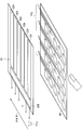
22 is a perspective view showing a configuration of a main part (a common electrode and a detection electrode for a sensor) of a display device provided with a touch sensor according to a first modification of the present invention.
23 is a perspective view showing a configuration of a main part (a common electrode and a detection electrode for a sensor) of a display device provided with a touch sensor according to a
24 is a perspective view showing the appearance of the display device according to Application Example 1 of the above-described embodiment or the like as seen from the front.
25A and 25B are perspective views showing the external appearance of the display device according to Application Example 2 of the above-described embodiment or the like when viewed from the front and rear, respectively.
26 is a perspective view showing the appearance of Application Example 3. Fig.
Fig. 27 is a perspective view showing the appearance of Application Example 4; Fig.
28A to 28G are a front view, a side view, a closed front view, a left side view, a right side view, a top view, and a bottom view, respectively, of Application Example 5;
이하, 본 발명의 실시 형태에 대해서, 도면을 참조하여 상세하게 설명한다. 또한, 설명은 이하의 순서대로 제공된다.BEST MODE FOR CARRYING OUT THE INVENTION Hereinafter, embodiments of the present invention will be described in detail with reference to the drawings. The description is given in the following order.
터치 검출 방식의 기본 원리 Basic principle of touch detection method
1. 제1 실시 형태(Vcom의 반전 전의 검출치를 사용한 반전 후의 물체 검출의 예) 1. First Embodiment (Example of Object Detection After Inversion Using Detected Value Before Inversion of Vcom)
2. 제2 실시 형태(표시 소자로서 횡전계 모드의 액정 소자를 사용한 예) 2. Second Embodiment (Example using a liquid crystal element of transverse electric field mode as a display element)
3. 변형예(변형예1,2: 공통 전극 및 센서용 검출 전극의 다른 구성예) 3. Modifications (
4. 적용예(터치 센서를 구비한 표시 장치의 전자 기기에의 적용예) 4. Application Example (Example of Application to Display Device with Touch Sensor to Electronic Device)
[터치 검출 방식의 기본 원리] [Basic principle of touch detection method]
우선 최초에, 도 1a 내지 도 3을 참조하여, 본 발명의 터치 센서를 구비한 표시 장치에서의 터치 검출 방식의 기본 원리에 대해서 설명한다. 이 터치 검출 방식은 정전 용량형 터치 센서로서 구현된다. 예를 들어, 도 1a에 도시된 바와 같이, 유전체 D를 개재시켜 서로 대향 배치된 한 쌍의 전극(구동 전극 E1 및 검출 전극 E2)을 사용하여, 용량 소자 C1을 구성한다. 이 방식은 도 1b에 나타낸 등가 회로로서 나타내진다. 구동 전극 E1, 검출 전극 E2 및 유전체 D에 의해 용량 소자 C1이 구성된다. 용량 소자 C1은 그 일단부가 AC 신호원(구동 신호원)(S)에 접속되고, 타단부 P는 저항기 R을 통해서 접지되고 전압 검출기(검출 회로)(DET)에 접속된다. AC 신호원(S)으로부터 구동 전극 E1(용량 소자 C1의 일단부)에 소정의 주파수(예를 들어 몇 kHz 내지 몇십 kHz정도)의 AC 구형파 Sg(도 3의 (B)부분)를 인가하면, 검출 전극 E2(용량 소자 C1의 타단부 P)에 도 3의 (A)부분에 나타낸 바와 같은 출력 파형(검출 신호 Vdet)이 나타난다. 또한, 이 AC 구형파 Sg는 후술하는 공통 구동 신호 Vcom에 상당한다.First, with reference to Figs. 1A to 3, the basic principle of a touch detection method in a display device having a touch sensor of the present invention will be described. This touch detection method is implemented as a capacitive touch sensor. For example, as shown in Fig. 1A, a pair of electrodes (drive electrode E1 and detection electrode E2) arranged opposite to each other with a dielectric D interposed therebetween is used to constitute a capacitive element C1. This scheme is shown as an equivalent circuit shown in Fig. 1B. The driving electrode E1, the detecting electrode E2, and the dielectric D constitute a capacitive element C1. One end of the capacitor C1 is connected to an AC signal source (drive signal source) S and the other end P is grounded through a resistor R and connected to a voltage detector (detection circuit) DET. When an AC square wave Sg (part (B) in Fig. 3) of a predetermined frequency (for example, several kHz to several kHz) is applied from the AC signal source S to the driving electrode E1 (one end of the capacitive element C1) An output waveform (detection signal Vdet) as shown in part (A) of Fig. 3 appears on the detection electrode E2 (the other end P of the capacitive element C1). This AC square wave Sg corresponds to the common drive signal Vcom described later.
손가락을 접촉하지 않은 상태에서는 도 1a 및 도 1b에 도시된 바와 같이, 용량 소자 C1 상에서 충방전이 수행될 때, 용량 소자 C1의 용량치에 따른 전류 I0가 흐른다. 이 때, 용량 소자 C1의 타단부 P의 전위 파형은 예를 들어 도 3의 (A)부분의 파형 V0와 같고, 이것이 전압 검출기 DET에 의해 검출된다.As shown in Figs. 1A and 1B, when the charge / discharge is performed on the capacitive element C1 in the state in which the finger is not in contact, a current I0 corresponding to the capacitance value of the capacitive element C1 flows. At this time, the potential waveform of the other end P of the capacitive element C1 is, for example, the waveform V0 of the portion (A) of Fig. 3, which is detected by the voltage detector DET.
한편, 손가락을 접촉한 상태에서는 도 2a 및 도 2b에 도시된 바와 같이, 손가락에 의해 형성되는 용량 소자 C2가 용량 소자 C1에 직렬로 추가된다. 이 상태에서는 용량 소자 C1, C2 상에서 충방전이 수행될 때, 각각 전류 I1, I2가 흐른다. 이 때, 용량 소자 C1의 타단부 P의 전위 파형은 예를 들어 도 3의 (A)부분의 파형 V1과 같고, 이것이 전압 검출기 DET에 의해 검출된다. 이 때, 타단부 P의 전위는 각각 용량 소자 C1, C2를 흐르는 전류 I1,I2의 값에 의해 정해지는 분압 전위이다. 이로 인해, 파형 V1은 비접촉 상태에서의 파형 V0보다도 작은 값이 된다. 전압 검출기 DET는 후술하는 바와 같이, 검출한 전압을 소정의 임계치 전압 Vth와 비교한다. 검출한 전압이 임계치 전압 이상이면, 전압 검출기 DET는 이것이 비접촉 상태에 있다고 판단한다. 한편, 검출한 전압이 임계치 전압 Vth 미만이면, 전압 검출기 DET는 이것이 접촉 상태에 있다고 판단한다. 이러한 방식으로, 터치 검출을 수행하는 것이 가능해진다.On the other hand, in a state in which the finger is in contact, as shown in Figs. 2A and 2B, the capacitive element C2 formed by the finger is added in series to the capacitive element C1. In this state, when charge and discharge are performed on the capacitive elements C1 and C2, currents I1 and I2 flow respectively. At this time, the potential waveform of the other end P of the capacitive element C1 is, for example, the waveform V1 of the portion (A) of Fig. 3, which is detected by the voltage detector DET. At this time, the potential of the other end P is the divided potential determined by the values of the currents I1 and I2 flowing through the capacitors C1 and C2, respectively. As a result, the waveform V1 becomes smaller than the waveform V0 in the non-contact state. The voltage detector DET compares the detected voltage with a predetermined threshold voltage Vth as described later. If the detected voltage is equal to or higher than the threshold voltage, the voltage detector DET judges that it is in the non-contact state. On the other hand, if the detected voltage is less than the threshold voltage Vth, the voltage detector DET determines that it is in the contact state. In this way, it becomes possible to perform touch detection.
[1.제1 실시 형태][1. First embodiment]
[표시 장치(1)의 구성예][Configuration example of display apparatus 1]
도 4는 본 발명의 제1 실시 형태에 관한 터치 센서를 구비한 표시 장치(1)의 주요부 단면 구조를 나타낸다. 이 표시 장치(1)는 표시 소자로서 액정 표시 소자를 사용하고, 이 액정 표시 소자에 원래 구비되어 있는 전극의 일부(후술하는 공통 전극(43)) 및 표시용 구동 신호(후술하는 공통 구동 신호 Vcom)를 사용하여, 정전 용량형 터치 센서를 구성한다.4 shows a cross-sectional structure of a main portion of a
도 4에 도시된 바와 같이, 이 표시 장치(1)는 화소 기판(2), 이 화소 기판(2)에 대향해서 배치된 대향 기판(4), 및 화소 기판(2)과 대향 기판(4) 사이에 삽입된 액정층(6)을 포함한다.4, the
화소 기판(2)은 회로 기판으로 기능하는 TFT 기판(21), 이 TFT 기판(21) 위로 매트릭스 형상으로 배치된 복수의 화소 전극(22)을 포함한다. TFT 기판(21)에는 각 화소 전극(22)을 구동하기 위한 도시하지 않은 표시 드라이버와 TFT(박막 트랜지스터) 이외에, 각 화소 전극(22)에 화소 신호를 공급하는 소스선과 각 TFT를 구동하는 게이트선 등의 배선이 형성된다. TFT 기판(21)에는 또한, 후술하는 터치 검출 동작을 행하는 검출 회로(8)(도 6)가 형성될 수도 있다.The
대향 기판(4)은 유리 기판(41), 이 유리 기판(41)의 한쪽 면에 형성된 컬러 필터(42)와, 이 컬러 필터(42) 상에 형성된 공통 전극(43)을 포함한다. 컬러 필터(42)에서, 예를 들어 적(R), 녹(G), 청(B)의 3색의 컬러 필터층은 주기적으로 정렬되고, 각 표시 화소(화소 전극(22))에 R, G, B의 3색이 1조로서 대응된다. 공통 전극(43)은 터치 검출 동작을 행하는 터치 센서의 일부를 구성하는 센서용 검출 전극으로서도 사용되고, 도 1a의 구동 전극 E1에 상당한다.The
공통 전극(43)은 콘택트 도전 기둥(7)에 의해 TFT 기판(21)과 연결된다. 이 콘택트 도전 기둥(7)을 통해 TFT 기판(21)으로부터 공통 전극(43)에 AC 구형파형의 공통 구동 신호 Vcom이 인가된다. 이 공통 구동 신호 Vcom은 화소 전극(22)에 인가되는 화소 전압과 함께 각 화소의 표시 전압을 한정하고, 터치 센서용 구동 신호로서도 사용된다. 이 공통 구동 신호 Vcom은 도 1a 및 도 1b의 구동 신호원 S로부터 공급되는 AC 구형파 Sg에 상당한다. 즉, 이 공통 구동 신호 Vcom은 매 소정의 주기마다 반전된다.The
유리 기판(41)의 다른 쪽의 면에는 센서용 검출 전극(44)(터치 검출 전극)이 형성된다. 또한, 이 센서용 검출 전극(44) 위에는 편광판(45)이 배치된다. 센서용 검출 전극(44)은 터치 센서의 일부를 구성하는 것으로, 도 1a의 검출 전극 E2에 상당한다.On the other surface of the
액정층(6)은 전계의 상태에 따라서 액정층(6)을 통과하는 광을 변조시키고, 예를 들어, TN(트위스트 네마틱), VA(수직 배향), ECB(전계 제어 복굴절) 등의 각종 모드의 액정으로 구성된다.The
액정층(6)과 화소 기판(2) 사이 및 액정층(6)과 대향 기판(4) 사이에는 각각 배향 막이 배치된다. 화소 기판(2)의 하면측에는 광 입사측 상의 편광판이 배치되지만, 도시를 생략한다.An alignment film is disposed between the
도 5는 대향 기판(4)의 공통 전극(43) 및 센서용 검출 전극(44)의 일 구성예를 도시한 사시도이다. 이 예에서, 공통 전극(43)은 도면의 좌우 방향으로 연장하는 복수의 스트라이프 형상의 전극 패턴(여기서는 일례로서 6개의 공통 전극(431) 내지 전극(436)을 취함)으로 분할된다. 각 전극 패턴에는 드라이버(43D)에 의해 공통 구동 신호 Vcom이 순차 공급되고, 후술하는 바와 같이 시분할적으로 선 순차 주사 구동이 행해진다. 한편, 센서용 검출 전극(44)은 공통 전극(43)의 전극 패턴의 연장 방향과 직교하는 방향으로 연장되는 복수의 스트라이프 형상의 전극 패턴을 포함한다. 센서용 검출 전극(44)의 각 전극 패턴으로부터 검출 신호 Vdet가 출력되어, 도 6에 도시된 검출 회로(8)에 입력된다.5 is a perspective view showing a configuration example of the
[구동 신호원 S 및 검출 회로(8)의 회로 구성예][Circuit example of drive signal source S and detection circuit (8)] [
도 6은 도 1b에 나타낸 구동 신호원 S와 검출 회로(8)를 포함하는 회로 구성예를, 타이밍 발생기로서 기능하는 타이밍 제어부(9)와 함께 나타낸다. 도 6에 도시된 용량 소자 C11 내지 C16은 도 5에 나타낸 각 공통 전극(431 내지 436)과 센서용 검출 전극(44) 사이에 형성된 (정전) 용량 소자에 각각 대응한다.Fig. 6 shows an example of a circuit configuration including the drive signal source S and the
구동 신호원 S는 각 용량 소자 C11 내지 C16마다 1개씩 제공되고, SW 제어부 (11), 2개의 스위치 소자(12, 15), 2개의 인버터 회로(131, 132) 및 연산 증폭기(14)를 포함한다. SW 제어부(11)는 스위치 소자(12)의 온·오프 상태를 제어하고, 이에 의해 전원 +V와 인버터 회로(131, 132) 사이의 접속 상태를 제어한다. 인버터 회로(131)의 입력 단자는 스위치 소자(12)의 일단부(전원 +V와는 반대측의 단자) 및 인버터 회로(132)의 출력 단자에 접속된다. 인버터 회로(131)의 출력 단자는 인버터 회로(132)의 입력 단자 및 연산 증폭기(14)의 입력 단자에 접속된다. 이에 의해, 이들의 인버터 회로(131, 132)는 소정의 펄스 신호를 출력하는 발진 회로로서 기능한다. 연산 증폭기(14)는 2개의 전원 +V, -V에 접속된다. 스위치 소자(15)는 타이밍 제어부(9)로부터 공급되는 타이밍 제어 신호 CTL1에 따라서 온·오프 상태를 제어한다. 구체적으로는 이 스위치 소자(15)에 의해, 각 용량 소자 C11 내지 C16의 일단부측(공통 전극(431 내지 436)측)이 연산 증폭기(14)의 출력 단자 또는 접지에 접속된다. 이에 의해, 구동 신호원 S로부터 용량 소자 C11 내지 C16에 공통 구동 신호 Vcom이 공급된다.The drive signal source S is provided for each of the capacitors C11 to C16 and includes an
검출 회로(8)(전압 검출기 DET)는 증폭부(81), A/D (아날로그/디지털) 변환부(83), 신호 처리부(84), 좌표 추출부(85) 및 전술한 저항기 R을 포함한다. 또한, 이 검출 회로(8)의 입력 단자 Tin은 각 용량 소자 C11 내지 C16의 타단부(센서용 검출 전극(44)측)에 접속되어 공유된다.The detection circuit 8 (voltage detector DET) includes an
증폭부(81)는 입력 단자 Tin으로부터 입력되는 검출 신호 Vdet를 증폭시키고, 신호 증폭용의 연산 증폭기(811), 2개의 저항기(812R, 813R) 및 2개의 캐패시터(812C, 813C)를 포함한다. 연산 증폭기(811)의 비반전 입력 단자(+)는 입력 단자 Tin에 접속되고, 연산 증폭기(811)의 출력 단자는 후술하는 A/D 변환부(83)의 입력 단자에 접속된다. 저항기(812R) 및 캐패시터(812C)의 각각의 일단부는 연산 증폭기(811)의 출력 단자에 접속되지만, 저항기(812R) 및 캐패시터(812C)의 타단부는 연산 증폭기(811)의 반전 입력 단자(-)에 접속된다. 또한, 저항기(813R)의 일단부는 저항기(812R) 및 캐패시터(812C)의 타단부에 접속되지만, 저항기(813R)의 타단부는 캐패시터(813C)를 통해서 접지에 접속된다. 이에 의해, 저항기(812R) 및 캐패시터(812C)는 고 주파수 성분은 차단시키고 저주파수 성분을 통과시키는 로우 패스 필터(LPF)로서 기능하고, 저항기(813R) 및 캐패시터(813C)는 고주파수 성분을 통과시키는 하이 패스 필터(HPF)로서 기능한다.The amplifying
저항기 R은 연산 증폭기(811)의 비반전 입력 단자(+)가 제공되는 측의 접점(P)과 접지 사이에 배치된다. 이 저항기 R은 센서용 검출 전극(44)의 플로팅 상태를 방지함으로써 안정 상태를 유지한다. 이에 의해, 검출 회로(8)에서, 검출 신호 Vdet의 신호치가 불안정하거나 변동하는 것을 방지하고, 이와 함께 이 저항기 R을 통해서 정전기를 접지로 소멸시키는(dissipated) 이점이 있다.The resistor R is arranged between the contact P on the side where the non-inverting input terminal (+) of the
A/D 변환부(83)는 증폭부(81)에서 증폭된 아날로그형의 검출 신호 Vdet를, 디지털의 검출 신호로 변환하며, 도시하지 않은 비교기를 포함한다. 이 비교기는 입력된 검출 신호의 전위와 소정의 임계치 전압 Vth(도 3 참조)의 전위를 비교한다. 또한, 이 A/D 변환부(83)에서의 A/D 변환 때의 샘플링 타이밍은 타이밍 제어부(9)에 의해 공급되는 타이밍 제어 신호 CTL2에 의해 제어된다.The A /
신호 처리부(84)는 A/D 변환부(83)로부터 출력되는 디지털의 검출 신호에 대하여 소정의 신호 처리(예를 들어, 디지털적인 노이즈 제거 처리, 주파수 정보를 위치 정보로 변환하는 처리)를 실시한다. 이 신호 처리부(84)는 또한 상세한 것은 후술하지만, 화상 신호의 기입 동작에 기인한 노이즈(반전 후 노이즈)의 영향을 제거하기 위한 소정의 연산 처리를 행한다.The
좌표 추출부(85)는 신호 처리부(84)로부터 출력되는 검출 신호(상기 반전 후 노이즈 제거후의 검출 신호)에 기초하여, 검출 결과(터치 되었는지의 여부, 및 터치되었을 경우에는 그 부분의 위치 좌표)를 구하고, 출력 단자 Tout로부터 검출 결과를 출력한다.The coordinate extracting
또한, 이러한 검출 회로(8)는 대향 기판(4) 상의 주변 영역(비 표시 영역 또는 프레임 영역)에 형성할 수도 있다. 이와 달리, 검출 회로(8)는 화소 기판(2) 상의 주변 영역에 형성해도 좋다. 그러나, 검출 회로(8)를 화소 기판(2) 상에 형성하면, 원래 화소 기판(2) 상에 형성되어 있는 표시 제어용의 각종 회로 소자 등과 검출 회로(8)의 집적화가 도모되어, 집적화에 의해 구현되는 회로의 간략화의 관점에서 보다 바람직하다. 이 경우에는 콘택트 도전 기둥(7)과 같은 콘택트 도전 기둥(도시하지 않음)으로 센서용 검출 전극(44)의 각 전극 패턴과 화소 기판(2) 상의 검출 회로(8)를 접속하고, 검출 신호 Vdet를 센서용 검출 전극(44)으로부터 검출 회로(8)에 전송할 수도 있다.This
[표시 장치(1)의 작용 및 효과][Operation and effect of the display device (1)
다음에, 본 실시 형태의 표시 장치(1)의 작용 및 효과에 대해서 설명한다.Next, the operation and effect of the
(기본 동작)(Basic operation)
이 표시 장치(1)에서는 화소 기판(2)의 표시 드라이버(도시하지 않음)가 공통 전극(43)의 각 전극 패턴(공통 전극 431 내지 436등)에 대하여 공통 구동 신호 Vcom을 선 순차적으로 공급한다. 이 표시 드라이버는 또한 소스선을 통해서 화소 전극(22)에 화소 신호(화상 신호)를 공급하고, 이 화소 신호의 공급에 동기하여 게이트선을 통해서 각 화소 전극의 TFT의 스위칭을 선 순차적으로 제어한다. 이에 의해, 액정층(6)에는 화소마다 공통 구동 신호 Vcom과 각 화소 신호에 의해 정해지는 종방향(기판에 수직인 방향)의 전계가 인가되고, 액정 상태의 변조가 행하여진다. 이 방식으로, 소위 반전 구동으로 표시가 행하여진다.In this
한편, 대향 기판(4)의 측에서는 공통 전극(43)의 각 전극 패턴과 센서용 검출 전극(44)의 각 전극 패턴과의 교차 부분에 각각 용량 소자 C1(용량 소자 C11 내지 C16)이 형성된다. 여기서, 예를 들어 도 7의 (A) 내지 (C)에 도시된 바와 같이, 공통 전극(43)의 각 전극 패턴에 공통 구동 신호 Vcom을 시분할적으로 순차 인가하면, 공통 구동 신호 Vcom이 인가된 공통 전극(43)의 전극 패턴과 센서용 검출 전극(44)의 각 전극 패턴과의 교차 부분에 형성되어 있는 일렬분의 용량 소자 C11 내지 C16의 각각에서 충방전이 행하여진다. 그 결과, 용량 소자 C1의 용량치에 따른 크기의 검출 신호 Vdet가 센서용 검출 전극(44)의 각 전극 패턴으로부터 출력된다. 대향 기판(4)의 표면에 유저의 손가락이 접촉하지 않은 상태에서는 이 검출 신호 Vdet의 크기는 거의 일정하다. 공통 구동 신호 Vcom의 스캔에 의해 충방전되는 용량 소자 C1의 라인이 선 순차적으로 이동해 간다.On the other hand, on the side of the
또한, 상술된 바와 같이 공통 전극(43)의 각 전극 패턴이 선 순차 구동될 때는 도 7에 도시된 바와 같이, 공통 전극(43)의 전극 패턴의 일부를 묶어서 선 순차 구동 동작을 행하도록 하는 것이 바람직하다. 구체적으로는, 이 일부의 전극 패턴으로 구성된 구동 라인 L은 복수 라인의 전극 패턴으로 이루어지는 검출용 구동 라인 L1과, 소수 라인(여기서는 1 라인)의 전극 패턴으로 이루어지는 표시용 구동 라인 L2를 포함한다. 이에 의해, 공통 전극(43)의 전극 패턴의 형상에 대응한 라인이나 얼룩 등이 발생하는 것에 의한 화질 열화를 억제하는 것이 가능해진다.7, when the respective electrode patterns of the
여기서, 대향 기판(4)의 표면의 임의의 장소에 유저의 손가락이 접촉하면, 그 터치 장소에 원래 형성되어 있는 용량 소자 C1에 손가락에 의한 용량 소자 C2가 부가된다. 그 결과, 그 터치 장소가 스캔된 시점(즉, 공통 전극(43)의 전극 패턴 중 그 터치 장소에 대응하는 전극 패턴에 공통 구동 신호 Vcom이 인가되었을 때)의 검출 신호 Vdet의 값이 다른 장소보다도 작아진다. 검출 회로(8)(도 6)는 이 검출 신호 Vdet를 임계치 전압 Vth와 비교한다. 이 검출 신호 Vdet가 임계치 전압 Vth보다 작으면, 검출 회로(8)는 그 장소를 터치 장소로서 판정한다. 이 터치 장소는 공통 구동 신호 Vcom의 인가 타이밍과, 임계치 전압 Vth 미만의 검출 신호 Vdet의 검출 타이밍에 기초하여 산출될 수 있다.Here, when the user's finger touches an arbitrary place on the surface of the
이와 같이 하여, 본 실시 형태의 터치 센서를 구비한 표시 장치(1)에서, 액정 표시 소자에 원래 구비된 공통 전극(43)은 한 쌍의 터치 센서용 전극(구동 전극과 검출 전극)의 하나로서 또한 사용된다. 또한, 표시용 구동 신호로서의 공통 구동 신호 Vcom이 터치 센서용 구동 신호로서 또한 사용된다. 이에 의해, 정전 용량형의 터치 센서에서, 새롭게 구비되는 전극으로서 센서용 검출 전극(44)만 제공되고, 또한, 터치 센서용 구동 신호를 새롭게 제공할 필요가 없다. 따라서, 구성이 간단하다.In this manner, in the
또한, 종래의 터치 패널을 구비한 표시 장치(일본 특허 공개 제2008-9750호 공보)에서는 센서에 흐르는 전류의 크기를 정확하게 측정하고, 그 측정치에 기초하여 터치 위치를 아날로그 연산에 의해 구한다. 이에 대해, 본 실시 형태의 표시 장치(1)에서는 터치의 유무에 따른 전류의 상대 변화(전위 변화)의 유무를 디지털적으로 검지하여, 간단한 검출 회로 구성으로 검출 정밀도를 높일 수 있다. 또한, 공통 구동 신호 Vcom의 인가용으로 원래 제공된 공통 전극(43)과 새롭게 제공된 센서용 검출 전극(44) 사이에 정전 용량을 형성하고, 이 정전 용량이 유저의 손가락의 접촉에 의해 변화하는 것을 이용해서 터치 검출을 행한다. 이로 인해, 본 발명의 터치 패널을 구비한 표시 장치는 유저의 전위가 종종 일정하지 않은 모바일 기기에 적용될 수 있다.Further, in a display device having a conventional touch panel (Japanese Patent Laid-Open No. 2008-9750), the magnitude of the current flowing through the sensor is accurately measured, and the touch position is obtained by analog calculation based on the measured value. On the other hand, in the
또한, 센서용 검출 전극(44)이 복수의 전극 패턴으로 분할되기 때문에, 각 복수의 전극 패턴은 개별로 시분할적으로 구동되어, 터치 위치를 검출할 수 있다.Further, since the
(특징적 부분의 작용; 노이즈 제거 처리를 사용한 검출 동작)(Operation of characteristic portion: detection operation using noise removal processing)
다음에, 도 8 내지 도 15를 참조하여, 본 발명의 특징적 부분의 하나인 노이즈 제거 처리를 사용한 검출 동작에 대해서 상세하게 설명한다. Next, the detection operation using noise removal processing, which is one of the characteristic parts of the present invention, will be described in detail with reference to Figs. 8 to 15. Fig.
우선, 도 8의 (A)에 도시된 바와 같이, 공통 구동 신호 Vcom이, 도 8의 (B), (C)에 나타낸 바와 같은 화상 표시 제어 중에 사용되는 구동 주기(화소 신호의 1H 주기)와 동기해서 반전을 행하는 경우, 검출 신호 Vdet의 검출 파형은 도 8의 (D) 내지 (F)에 나타낸 결과를 가져온다. 즉, 검출 신호 Vdet는 상술한 반전과 동기해서 반전을 행하고, 전술한 저항기 R에 흐르는 리크 전류에 기인한 반전 후에 서서히 신호치가 감쇠한다. 또한, 도 8에 나타낸 검출 파형(도 8의 (D) 내지 (F))에서는 설명상의 편의를 위해 후술하는 반전 후 노이즈의 영향을 제거한 것으로 가정하여 도시한다.First, as shown in Fig. 8A, the common drive signal Vcom is divided into a drive cycle (1H cycle of the pixel signal) used during image display control as shown in Figs. 8B and 8C When the inversion is performed in synchronization, the detection waveform of the detection signal Vdet results in the results shown in (D) to (F) in FIG. That is, the detection signal Vdet is inverted in synchronization with the above-described inversion, and the signal value is gradually attenuated after the inversion due to the leak current flowing in the resistor R described above. 8 (D) to 8 (F) shown in Fig. 8, it is assumed that the influence of noise after inversion is removed for convenience of explanation.
이 때, 예를 들어 도 8의 (B), (C)에 나타낸 바와 같은 백색 기입시나 흑색 기입시 등의 화소 신호(화상 신호)의 기입 시에는 검출 신호 Vdet의 검출 파형에 예를 들어 도 8의 (E), (F)에 도시된 바와 같이, 이 기입에 기인한 노이즈가 포함된다. 구체적으로는 1H 주기는 화상 신호가 인가되지 않는 비 기입 주기 ΔtA와, 화상 신호가 인가되는 기입 주기 ΔtB로 구성되고, 이 중의 기입 주기 ΔtB에 있어서, 화소 신호의 계조 레벨에 따른 검출 파형의 변동이 발생한다. 즉, 그 시점에서의 (반전 후의) 화상 신호의 계조 레벨에 따라, 도 8의 (E), (F)에서 화살표로 나타낸 바와 같은 반전 후의 화상 신호에 기인한 반전 후 노이즈가 검출 신호 Vdet의 검출 파형에 포함된다. 구체적으로는 흑색 기입 시에는 공통 구동 신호 Vcom과 동일 위상에 반전 후 노이즈가 포함되는 반면, 백색 기입 시에는 공통 구동 신호 Vcom과 반대 위상에 반전 후 노이즈가 포함된다. 이와 같이 하여, 기입 주기 ΔtB동안에는 검출 신호 Vdet의 검출 파형이 반전 후 노이즈에 의해 화소 신호의 계조 레벨에 따라서 변동하고, 따라서, 물체의 접촉의 유무 등과 같은 팩터에 의한 검출 파형의 변화(도 3의 (A) 부분)로부터 이러한 변화를 분별하는 것이 어렵다.At this time, at the time of writing pixel signals (image signals) such as white writing or black writing as shown in Figs. 8 (B) and 8 (C), the detection waveform of the detection signal Vdet, for example, As shown in (E) and (F) in FIG. More specifically, the 1H period is composed of a non-writing period DELTA tA in which no image signal is applied and a writing period DELTA tB in which an image signal is applied. In the writing period DELTA tB, a variation in the detection waveform depending on the gradation level of the pixel signal Occurs. That is, according to the gradation level of the image signal (after the inversion) at that time point, the noise after the inversion due to the inverted image signal as indicated by the arrows in (E) and (F) Is included in the waveform. More specifically, noise is included in the same phase as the common drive signal Vcom during the black write, while noise is included after the inversion in the opposite phase to the common drive signal Vcom in the white write. In this way, during the writing period? TB, the detection waveform of the detection signal Vdet fluctuates according to the gradation level of the pixel signal due to the noise after the inversion, and therefore the change of the detection waveform by the factor such as the presence or absence of contact of the object (Part (A)).
한편, 예를 들어 도 9에 도시된 바와 같이, 공통 구동 신호 Vcom의 반전 직후의 시간에 대응하는 비 기입 주기 ΔtA 중에는 기입 주기 ΔtB와 비교해서 물체의 접촉에 의한 전압 변화량이 매우 크다. 이로 인해, 물체의 접촉의 유무 등의 팩터에 의한 검출 파형의 변화 성분을 제거하고 노이즈 제거 처리로부터 이 성분을 분리하는 관점에서, 검출 회로(8)의 A/D 변환부(83)는 후술하는 반전 전의 검출 신호를 그 반전 직전 시에 취득하도록 하는 것이 바람직하다. 또한, 물체의 접촉의 유무 등의 팩터에 대한 검출 감도가 높고 후술하는 반전 후 노이즈의 영향이 작은 점을 고려하면, 후술하는 반전 후의 검출 동작은 그 반전 후의 화상 신호의 기입 동작의 개시전의 시간(비 기입 주기 ΔtA)에 행하는 것이 바람직하다.On the other hand, as shown in Fig. 9, for example, in the non-writing period DELTA tA corresponding to the time immediately after the inversion of the common driving signal Vcom, the voltage variation due to the contact of the object is very large as compared with the writing period DELTA tB. Thus, from the viewpoint of removing the change component of the detection waveform due to the factor such as the presence or absence of contact of the object and separating this component from the noise removal processing, the A /
여기서, 예를 들어 도 10에 도시된 바와 같이, 실제로는 반전 전의 검출 신호에 포함되는 화상 신호에 기인한 노이즈(즉, 반전 전 노이즈; 도면 중의 전위차 ΔVB에 대응)는 반전 후의 검출 신호의 비 기입 주기 ΔtA 중에, 또한 반전 후 노이즈로서 발생한다. 즉, 반전 전 노이즈에 대응하는 전위차 ΔVB의 크기(즉, 반전 전의 화소 신호의 계조 레벨에 따른 전위)에 따라서, 반전 후 노이즈에 대응하는 전위차 ΔVA의 크기가 규정된다. 원리적으로는 전위차 ΔVA는 전위차 ΔVB와 동일하고, 반전시의 변화량은 일정하게 유지된다. 그러나, 검출 신호 Vdet의 지연이나 (도시하지 않은) 노이즈 필터 등의 추가에 의해 파형의 지연이 발생하고, 그 결과로서 반전 전에 이론 값 이상의 기입 노이즈가 포함되는 경우가 종종 발생한다. 그로 인해, 전위차 ΔVA가 전위차 ΔVB와 같지 않고, ΔVA=f(ΔVB)와 같은 계산식이나 레퍼런스 테이블 등을 사용한 처리가 필요한 경우가 있다.10, the noise due to the image signal included in the detection signal before the inversion (that is, the noise before reversal (corresponding to the potential difference? VB in the drawing) is the non-write Occurs during the period DELTA tA, and also as noise after the inversion. That is, the magnitude of the potential difference? VA corresponding to the noise after the inversion is defined according to the magnitude of the potential difference? VB corresponding to the before-before-noise (that is, the potential according to the gradation level of the pixel signal before inversion). In principle, the potential difference? VA is equal to the potential difference? VB, and the amount of change during inversion is kept constant. However, the delay of the detection signal Vdet or the addition of a noise filter (not shown) or the like causes a delay of the waveform, and as a result, a write noise higher than the theoretical value is often included before inversion. Therefore, the potential difference? VA is not equal to the potential difference? VB, and a process using a calculation formula such as? VA = f (? VB) or a process using a reference table may be required.
따라서, 본 실시 형태에서는 검출 회로(8) 내의 신호 처리부(84) 및 좌표 추출부(85)에서 예를 들어 도 11에 도시된 바와 같이, 상기한 노이즈를 제거하는 물체 검출을 행한다. 구체적으로는 검출 회로(8)에서는 공통 구동 신호 Vcom의 반전 전후에, 반전 전의 검출 신호 Vdet를 사용해서 반전 후의 검출 동작을 행한다. 보다 구체적으로는 신호 처리부(84)는 반전 전의 검출 신호 Vdet에 기초하여, 그 반전 전에 행해지는 화상 신호의 기입 동작의 결과로서 반전 후의 검출 신호 Vdet에 포함되는 반전 후 노이즈가 제거된 노이즈 제거 신호(즉, 노이즈 제거된 검출 신호)를 취득한다. 그리고, 좌표 추출부(85)는 노이즈 제거 신호를 사용하여 반전 후의 검출 동작을 행한다.Therefore, in the present embodiment, the
이에 의해, 반전 전에 행해지는 화상 신호의 기입 동작의 결과로서 반전 후의 검출 신호 Vdet에 포함되는 노이즈(반전 후 노이즈)의 영향을 제거하면서, 반전 후의 검출 동작을 행할 수 있다. Thereby, the detection operation after the inversion can be performed while eliminating the influence of the noise (after-inverted noise) included in the detection signal Vdet after the inversion as a result of the write operation of the image signal performed before the inversion.
여기서, 도 11에 도시된 바와 같이, 반전 전의 검출 신호 Vdet(즉, 제1 검출 신호)의 노이즈 제거 전후의 전위 VB0, VB1, 반전 후의 검출 신호 Vdet(즉, 제2 검출 신호)의 노이즈 제거 전후의 전위 VA0, VA1, 및 전술한 전위차 ΔVB, ΔVA를 각각 규정한다. 다음에, 검출 회로(8)에서는 예를 들어 도 12 내지 도 14에 나타낸 바와 같은 방법(방법1 내지 방법3)을 사용하여, 노이즈를 제거하는 물체 검출을 행할 수 있다.Here, as shown in Fig. 11, before and after noise removal of the detection signal Vdet (that is, the first detection signal) before the inversion, and before and after the noise removal of the detection signals Vdet VA1 and VA1, and the above-mentioned potential differences? VB and? VA, respectively. Next, in the
(방법1)(Method 1)
우선, 도 12에 나타낸 방법1에서는 최초에, 반전 전후 각각에서의 노이즈 제거전의 전위인 전위 VA0, VB0(검출치)과, 반전 전에서의 노이즈 제거후의 전위인 전위 VB1(실험치에 기초한 데이터)을 각각 취득한다(스텝 S11). 다음에, 취득한 전위 VB0, VB1에 기초하여, ΔVB=(VB0-VB1)에 의해 규정되는 연산식을 사용함으로써, 반전 전에 행해지는 화상 신호의 기입 동작의 결과로서 반전 전의 검출 신호에 포함되는 반전 전 노이즈(전위차)ΔVB를 구한다(스텝 S12). 다음에, 이 반전 전 노이즈 ΔVB에 기초하여, 반전 후 노이즈에 대응하는 반전 후 노이즈(전위차)ΔVA를 구한다(스텝 S13). ΔVA=f(ΔVB)에 의해 규정되는 소정의 연산식 또는 ΔVB와 ΔVA 사이의 관계를 규정하는 소정의 LUT(룩업 테이블)을 사용함으로써, 반전 후 노이즈(전위차)ΔVA를 구한다. 다음에, 이 반전 후 노이즈 ΔVA를, 스텝 S11에서 취득한 전위 VA0으로부터 빼는 것에 의해(즉, VA1=VA0-ΔVA), 노이즈 제거 신호의 전위 VA1을 취득한다(스텝 S14). 그리고, 이 노이즈 제거 신호의 전위 VA1과, 소정의 임계치 전위 Vth와의 크기를 비교함으로써, 반전 후의 검출 동작(물체의 접촉의 유무 등의 팩터의 검출)을 행한다(스텝 S15).First, in
(방법2)(Method 2)
또한, 도 13에 나타낸 방법2에서는 최초에, 반전 전에서의 노이즈 제거전의 전위인 전위 VB0(검출치)과, 반전 전에서의 노이즈 제거후의 전위인 전위 VB1을 각각 취득한다(스텝 S21). 다음에, 취득한 전위 VB0, VB1에 기초하여, ΔVB=(VB0-VB1)에 의해 규정되는 연산식을 사용함으로써, 반전 전 노이즈량(전위차)ΔVB를 구한다(스텝 S22). 다음에, 이 반전 전 노이즈 ΔVB에 기초하여, 노이즈 제거 신호의 전위 VA1을 구한다(스텝 S23). VA1=f(ΔVB)에 의해 규정되는 소정의 연산식 또는(ΔVB, VA1)사이의 관계를 규정하는 소정의 LUT를 사용함으로써, 노이즈 제거 신호의 전위 VA1을 구한다. 그리고, 이 노이즈 제거 신호의 전위 VA1과, 소정의 임계치 전위 Vth와의 크기를 비교함으로써, 반전 후의 검출 동작(물체의 접촉의 유무 등의 팩터의 검출)을 행한다(스텝 S24).In the
(방법3)(Method 3)
도 14에 나타낸 방법3에서는 최초에, 반전 후에서의 노이즈 제거 전의 전위인 전위 VA0(검출치)과, 반전 전에서의 노이즈 제거전의 전위인 전위 VB0(검출치)을 각각 취득한다(스텝 S31). 다음에, 취득한 전위 VA0, VB0에 기초하여, 노이즈 제거 신호의 전위 VA1을 구한다(스텝 S32). VA1=f(VA0, VB0)=(VA0-α×VB0) (α: 소정의 계수)에 의해 규정되는 연산식 또는 VA0, VB0, VA1 사이의 관계를 규정하는 소정의 LUT(룩업 테이블)를 사용함으로써, 노이즈 제거 신호의 전위 VA1을 구한다. 그리고, 이 노이즈 제거 신호의 전위 VA1과, 소정의 임계값 전위 Vth와의 크기를 비교함으로써, 반전 후의 검출 동작(물체의 접촉의 유무 등의 팩터의 검출)을 행한다(스텝 S33).In the method 3 shown in Fig. 14, the potential VA0 (detection value), which is the potential before the noise removal after the inversion, and the potential VB0 (the detection value), which is the potential before the noise removal before the inversion, are acquired respectively (step S31) . Next, based on the acquired potentials VA0 and VB0, the potential VA1 of the noise canceling signal is obtained (step S32). A predetermined LUT (lookup table) that defines the relationship between VA0, VB0, and VA1 is used, which is defined by VA1 = f (VA0, VB0) = (VA0-? VB0) Thereby obtaining the potential VA1 of the noise canceling signal. Then, a detection operation after the inversion (detection of a factor such as the presence or absence of contact of an object) is performed by comparing the potential VA1 of the noise removal signal with the predetermined threshold potential Vth (step S33).
여기서, 도 15는 검출 방법에 따라 변화하는 백색 기입시 및 흑색 기입 시의 검출 신호치 사이의 차이의 일례를 나타낸다. 도 15에 도시된 바와 같이, 기입 주기 ΔtB의 검출 결과와 비 기입 주기 ΔtA의 검출 결과를 비교하면, 지금까지 설명한 본 실시 형태의 방법을 사용한 검출 결과가 백색 기입시 및 흑색 기입 시의 검출 신호치의 차이가 작다. 구체적으로는 기입 주기 ΔtB의 검출에서는 검출 신호치간의 차이는 0.50V, 비 기입 주기 ΔtA의 검출에서는 검출 신호치의 차이는 0.20V인 반면, 본 실시 형태의 방법을 사용한 검출에서는 검출 신호치의 차이는 0.01V이다.Here, FIG. 15 shows an example of the difference between the detection signal values at the time of white writing and at the time of black writing which change according to the detection method. As shown in Fig. 15, when the detection result of the writing period DELTA tB is compared with the detection result of the non-writing period DELTA tA, the detection results using the method of the present embodiment described so far are the values of the detection signal values at the time of white writing and at the time of black writing The difference is small. Specifically, in the detection of the writing period? TB, the difference between the detection signal values is 0.50 V, and in the detection of the non-writing period? TA, the difference in the detection signal values is 0.20 V. On the other hand, in the detection using the method of this embodiment, V.
이상과 같이 본 실시 형태에서는 정전 용량의 변화에 따라서 터치 검출 전극으로부터 얻어지는 검출 신호 Vdet에 기초하여 물체의 접촉 위치를 검출하고, 검출 회로(8)는 공통 구동 신호 Vcom에서 반전 전의 검출 신호 Vdet를 사용해서 반전 후의 반전 주기에서 검출 동작을 행한다. 따라서, 종래와 같은 차폐층을 이용하지 않고, 상기 반전 후 노이즈의 영향을 제거하면서, 반전 후의 반전 주기에서 검출 동작을 행할 수 있다. 따라서, 정전 용량형의 터치 센서를 구비한 표시 장치에서, 차폐층을 사용하지 않고 물체의 검출 정밀도를 향상시키는 것이 가능해진다.As described above, in this embodiment, the contact position of the object is detected based on the detection signal Vdet obtained from the touch detection electrode in accordance with the change of the capacitance, and the
[2. 제2 실시 형태] [2. Second Embodiment]
다음에, 본 발명의 제2 실시 형태에 대해서 설명한다. 본 실시 형태는 표시 소자로서 횡전계 모드의 액정 소자를 사용한다는 점에서 상기 제1 실시 형태와 상이하다.Next, a second embodiment of the present invention will be described. The present embodiment is different from the above-described first embodiment in that a transverse electric field mode liquid crystal element is used as a display element.
[표시 장치(1B)의 구성예][Configuration example of the
도 16은 본 실시 형태의 터치 센서를 구비한 표시 장치(1B)의 주요부 단면 구조를 나타낸다. 도 17a 및 도 17b는 이 표시 장치(1B)의 화소 기판(후술하는 화소 기판(2B))의 상세 구성을 나타낸다. 도 17a는 단면 구성을, 도 17b는 평면 구성을 나타낸다. 도 18a 및 도 18b는 표시 장치(1B)의 사시 구조를 개략적으로 나타낸다. 또한, 이들의 도면에서, 상기 제1 실시 형태와 동일부분에는 동일한 부호를 부여하고, 적절히 설명을 생략한다.Fig. 16 shows a cross-sectional structure of a main part of a
표시 장치(1B)는 화소 기판(2B), 이 화소 기판(2B)에 대향해서 배치된 대향 기판(4B)과, 화소 기판(2B)과 대향 기판(4B) 사이에 삽입된 액정층(6)을 포함한다.The
화소 기판(2B)은 TFT 기판(21), 이 TFT 기판(21) 위에 배치된 공통 전극(43), 이 공통 전극(43) 위에 절연층(23)을 개재하여 매트릭스 형상으로 배치된 복수의 화소 전극(22)을 포함한다. TFT 기판(21)에는 각 화소 전극(22)을 구동하기 위한 도시하지 않은 표시 드라이버나 TFT의 이외에, 각 화소 전극(22)에 화소 신호를 공급하는 신호선(소스선)(25) 및 각 TFT를 구동하는 게이트선(126) 등의 배선이 형성된다(도 17a 및 도 17b). TFT 기판(21)에는 또한, 터치 검출 동작을 행하는 검출 회로(8)(도 6)가 형성된다. 공통 전극(43)은 터치 검출 동작을 행하는 터치 센서의 일부를 구성하는 센서용 구동 전극으로서도 사용된다. 공통 전극(43)은 도 1a의 구동 전극 E1에 상당한다.The
대향 기판(4B)은 유리 기판(41), 이 유리 기판(41)의 한쪽 면에 형성된 컬러 필터(42)를 포함한다. 유리 기판(41)의 다른 쪽의 면에는 센서용 검출 전극(44)이 형성된다. 또한, 이 센서용 검출 전극(44) 위에는 편광판(45)이 배치된다. 센서용 검출 전극(44)은 터치 센서의 일부를 구성하는 것으로, 도 1a의 검출 전극 E2에 상당한다. 센서용 검출 전극(44)은 도 5에 도시된 바와 같이, 복수의 전극 패턴으로 분할된다. 센서용 검출 전극(44)은 박막 형성 프로세스에 의해 대향 기판(4B) 위에 직접적으로 형성해도 좋지만, 대향 기판(4B) 위에 간접적으로 형성해도 좋다. 이 경우에는 센서용 검출 전극(44)을 도시하지 않은 필름 기판 위에 형성할 수 있고, 이 센서용 검출 전극(44)이 형성된 필름 기판을 대향 기판(4B)의 표면에 부착할 수도 있다. 또한, 이 경우, 유리 기판(41)과 편광판(45) 사이뿐만 아니라 편광판(45)의 상면에 부착하는 것도 가능하다. 또한, 편광판(45)을 구성하는 필름 내에 센서용 검출 전극(44)을 형성할 수 있다.The counter substrate 4B includes a
TFT 기판(21)으로부터 공통 전극(43)에 AC 구형파형의 공통 구동 신호 Vcom이 인가된다. 이 공통 구동 신호 Vcom은 화소 전극(22)에 인가되는 화소 전압과 각 화소의 표시 전압을 한정하고, 터치 센서용 구동 신호로서도 사용된다. 공통 구동 신호 Vcom은 도 1a 및 도 1b의 구동 신호원 S로부터 공급되는 AC 구형파 Sg에 상당한다.A common driving signal Vcom of an AC square wave form is applied to the
액정층(6)은 액정층(6)을 통과하는 광을 변조하고, FFS(프린지 필드 스위칭) 모드나, IPS(면내 스위칭) 모드의 횡전계 모드의 액정으로 구성된다. The
화소 기판(2B)의 공통 전극(43) 및 센서용 검출 전극(44)의 구성은 예를 들어 도 5에 나타낸 것과 유사하다. 공통 전극(43) 및 센서용 검출 전극(44)은 복수의 패턴으로 각각 형성되고, 공통 전극(43)의 전극 패턴과 대향 기판(4B)의 센서용 검출 전극(44)의 전극 패턴은 서로 교차하면서 연장하도록 형성된다.The configuration of the
여기서, 도 18a 및 도 18b를 참조하여, 보다 상세하게 설명한다. 여기에 나타낸 바와 같은 FFS 모드의 액정 소자에서는 화소 기판(2B) 상에 형성된 공통 전극(43)의 상에 절연층(23)을 사이에 두고 빗살 모양으로 패터닝된 화소 전극(22)이 배치되고, 화소 전극(22)을 덮는 배향 막(26)이 형성된다. 이 배향 막(26)과 대향 기판(4B)측의 배향 막(46) 사이에, 액정층(6)이 지지된다. 2매의 편광판(24, 45)은 크로스니콜(cross-nichols)의 상태로 배치된다. 2매의 배향 막(26, 46)의 마찰 방향은 2매의 편광판(24, 45)의 한쪽의 투과 축과 일치한다. 여기에서, 마찰 방향이 광 출사측의 편광판(45)의 투과 축과 일치하고 있을 경우를 도시한다. 또한, 2매의 배향 막(26, 46)의 마찰 방향 및 편광판(45)의 투과 축의 방향은 액정 분자가 회전하는 방향이 규정되는 범위에서, 화소 전극(22)의 연장 방향(빗살의 길이 방향)에 대략 평행하게 설정된다.Here, this will be described in more detail with reference to Figs. 18A and 18B. In the liquid crystal device of the FFS mode as shown here, a
[표시 장치(1B)의 작용 및 효과][Function and effect of the
다음에, 본 실시 형태의 표시 장치(1B)의 작용 및 효과에 대해서 설명한다.Next, the operation and effects of the
(기본 동작) (Basic operation)
최초에, 도 18a 내지 도 19b를 참조하여, FFS 모드의 액정 소자의 표시 동작 원리에 대해서 간단하게 설명한다. 도 19a 및 도 19b는 액정 소자의 주요부 단면을 확대해서 나타낸다. 도 18a 및 도 19a는 전계 비인가 시의 액정 소자의 상태, 도 18b 및 도 19b는 전계 인가 시의 액정 소자의 상태를 나타낸다.First, with reference to Figs. 18A to 19B, the principle of display operation of the FFS mode liquid crystal element will be briefly described. Figs. 19A and 19B are enlarged views of a main section of the liquid crystal element. Figs. 18A and 19A show the state of the liquid crystal element when no electric field is applied, and Figs. 18B and 19B show the state of the liquid crystal element when applying an electric field.
공통 전극(43)과 화소 전극(22) 사이에 전압을 인가하지 않고 있는 상태에서는(도 18a 및 도 19a), 액정층(6)의 액정 분자(61)의 축이 광 입사측의 편광판(24)의 투과 축과 직교하고, 광 출사측의 편광판(45)의 투과 축에 평행하다. 이로 인해, 광 입사측의 편광판(24)을 투과한 입사광 "h"는 액정층(6) 내의 위상차를 발생시키지 않고 광 출사측의 편광판(45)에 도달하고, 편광판(45)에 흡수되어, 흑색이 표시된다. 한편, 공통 전극(43)과 화소 전극(22) 사이에 전압을 인가한 상태에서는(도 18b 및 도 19b), 액정 분자(61)의 배향 방향이 화소 전극간에 발생하는 횡전계 E에 의해, 화소 전극(22)의 연장 방향에 대하여 기울어진 방향으로 회전한다. 이 때, 액정층(6)의 두께 방향의 대략 중앙에 위치하는 액정 분자(61)가 약 45도 회전하도록 백색 표시 시의 전계 강도를 최적화한다. 이에 의해, 입사측의 편광판(24)을 투과한 후 입사광 h가 액정층(6)을 투과하는 동안 액정층(6)에 위상차가 발생한다. 따라서, 입사광 h는 90도 회전한 직선 편광이 되고, 출사측의 편광판(45)을 통과하여, 백색이 표시된다.18A and 19A), the axis of the
다음에, 표시 장치(1B)의 표시 제어 동작 및 터치 검출 동작에 대해서 설명한다. 이들의 동작은 상기 제1 실시 형태의 동작과 마찬가지이므로, 일부 설명은 적절히 생략한다.Next, the display control operation and the touch detection operation of the
화소 기판(2B)의 표시 드라이버(도시하지 않음)는 공통 전극(43)의 각 전극 패턴에 대하여 공통 구동 신호 Vcom을 선 순차적으로 공급한다. 표시 드라이버는 또한 소스선(25)을 통해서 화소 전극(22)에 화소 신호를 공급하고, 화소 신호의 공급에 동기하여 게이트선(126)을 통해서 각 화소 전극의 TFT의 스위칭을 선 순차적으로 제어한다. 이에 의해, 액정층(6)에는 화소 마다 공통 구동 신호 Vcom과 각 화소 신호에 의해 정해지는 횡방향(기판에 평행한 방향)의 전계가 인가되어서 액정 상태의 변조가 행하여진다. 이 방식으로, 소위 반전 구동에 의한 표시가 행하여진다.A display driver (not shown) of the
한편, 대향 기판(4B)의 측에서는 공통 전극(43)의 각 전극 패턴에, 공통 구동 신호 Vcom을 시분할적으로 순차 인가된다. 그 후, 공통 구동 신호 Vcom가 인가된 공통 전극(43)의 전극 패턴과 센서용 검출 전극(44)의 각 전극 패턴과의 교차 부분에 형성된 일 라인의 용량 소자 C1(C11 내지 C16)의 각각에서 충방전이 행하여진다. 용량 소자 C1의 용량치에 따른 크기의 검출 신호 Vdet가 센서용 검출 전극(44)의 각 전극 패턴으로부터 각각 출력된다. 대향 기판(4B)의 표면에 유저의 손가락이 접촉되지 않은 상태에서는 이 검출 신호 Vdet의 크기는 대략 일정하다. 대향 기판(4B)의 표면의 임의의 장소에 유저의 손가락이 접촉하면, 그 터치 장소에 원래 형성되어 있는 용량 소자 C1에 손가락에 의한 용량 소자 C2가 부가된다. 그 결과, 그 터치 장소가 스캔된 시점의 검출 신호 Vdet의 값은 다른 장소보다도 작아진다. 검출 회로(8)(도 6)는 이 검출 신호 Vdet를 임계치 전압 Vth와 비교한다. 검출 신호 Vdet가 임계치 전압 Vth 미만의 경우에, 검출 회로(8)는 그 장소를 터치 장소로서 판정한다. 이 터치 장소는 공통 구동 신호 Vcom의 인가 타이밍과 임계치 전압 Vth 미만의 검출 신호 Vdet의 검출 타이밍에 기초하여 판정한다.On the other hand, on the side of the counter substrate 4B, the common drive signal Vcom is sequentially applied to each electrode pattern of the
이상과 같이 본 실시 형태에서는 상기 제1 실시 형태와 마찬가지로, 액정 표시 소자에 원래 구비된 공통 전극(43)을 구동 전극과 검출 전극을 포함하는 한 쌍의 터치 센서용 전극의 하나로서 사용하고, 표시용 구동 신호로서 기능하는 공통 구동 신호 Vcom을 터치 센서용 구동 신호로서 공용하도록 정전 용량형 터치 센서를 구성한다. 따라서, 새롭게 설치하는 전극으로 센서용 검출 전극(44)만 제공해도 될 수 있고, 또한, 터치 센서용 구동 신호를 새롭게 준비할 필요가 없다. 따라서, 구성이 간단하다.As described above, in the present embodiment, the
또한, 본 실시 형태에 있어서도, 상기 제1 실시 형태에서 설명한 검출 회로(8)를 설치하도록 했으므로, 상기 제1 실시 형태와 유사한 작용에 의해 마찬가지의 효과를 얻는 것이 가능해진다. 즉, 정전 용량형의 터치 센서를 구비한 표시 장치에서, 차폐층을 사용하지 않고 물체의 검출 정밀도를 향상시키는 것이 가능해진다.Also in this embodiment, since the
특히, 본 실시 형태에서는 터치 센서용 구동 전극으로 기능하는 공통 전극(43)이 화소 기판(2)의 측(TFT 기판(21) 위)에 배치된 구조를 갖기 때문에, TFT 기판(21)으로부터 공통 전극(43)에 공통 구동 신호 Vcom을 공급하는 것이 매우 용이하다. 동시에, 필요한 회로, 전극 패턴 및 배선 등을 화소 기판(2)에 집중시킬 수 있어서, 회로의 집적화를 구현할 수 있다. 따라서, 상기 제1 실시 형태에서 필요한 화소 기판(2)측으로부터 대향 기판(4)측으로 공통 구동 신호 Vcom의 공급 경로(콘택트 도전 기둥(7))가 불필요하여, 구조가 보다 간단해진다.Particularly, in this embodiment, since the
또한, 상기와 같이, 터치 센서용 구동 전극으로서 기능하는 공통 전극(43)이 화소 기판(2B)의 측에 제공되고, 이와 함께, 이 화소 기판(2B) 위로 소스선(25)과 게이트선(126)이 제공되기 때문에, 본 실시 형태에서는 특히 반전 후 노이즈의 영향을 받기 쉬운 구조가 된다. 이러한 이유로, 본 실시 형태의 표시 장치(1B)에서는 반전 후 노이즈의 영향을 제거해서 검출 동작을 행하는 이점이 특히 크다.A
또한, 검출 회로(8)(도 6)가 대향 기판(4B) 상의 주변 영역(비 표시 영역 또는 프레임 영역)에 형성하도록 해도 좋지만, 화소 기판(2B) 상의 주변 영역에 검출 회로(8)를 형성하는 것이 바람직하다. 검출 회로(8)를 화소 기판(2B) 상에 형성하면, 검출 회로(8)와 원래 화소 기판(2) 상에 형성되어 있는 표시 제어용의 각종 회로 소자 등이 집적화될 수 있다.6) may be formed in the peripheral region (non-display region or frame region) on the counter substrate 4B, but the
[제2 실시 형태의 변형예] [Modified example of the second embodiment]
본 실시 형태에서는 센서용 검출 전극(44)을 유리 기판(41)의 표면측(액정층(6)과 대향하는 측의 반대측)에 제공한다. 그러나, 이는 다음과 같은 변형이 가능하다.In the present embodiment, the
예를 들어 도 20에 나타낸 표시 장치(1C)에 도시된 바와 같이, 대향 기판(4C)에서, 센서용 검출 전극(44)을 컬러 필터(42)보다도 액정층(6)측에 제공할 수도 있다.It is also possible to provide the
이와 달리, 도 21에 나타낸 표시 장치(1D)와 같이, 대향 기판(4D)에서, 센서용 검출 전극(44)을 유리 기판(41)과 컬러 필터(42) 사이에 제공할 수도 있다. 횡전계 모드의 경우, 종방향으로 전극이 있으면 종방향으로 전계가 인가되고, 액정의 상승으로 인해 시야각 등이 크게 악화될 수 있다. 따라서, 이 표시 장치(1D)와 같이, 컬러 필터(42) 등의 유전체를 액정층(6)과 센서용 검출 전극(44) 사이에 개재하도록 센서용 검출 전극(44)을 배치하면, 이 문제는 크게 저감할 수 있다.Alternatively, the
[3. 변형예(변형예1, 2)][3. Modifications (
다음에, 상기 제1 및 제2 실시 형태와 공통인 변형예1 및 2에 대해서 설명한다. 상기 실시 형태에서는 도 5에 도시된 바와 같이, 각각의 공통 전극(43) 및 센서용 검출 전극(44)은 복수의 전극 패턴으로 형성되고, 공통 전극(43)의 전극 패턴 및 센서용 검출 전극(44)은 서로 교차하면서 연장하도록 형성된다. 그러나, 공통 전극(43)과 센서용 검출 전극(44)의 구성은 이러한 예에 한정되지 않는다. 또한, 다음 설명에서, 상기 제1 및 제2 실시 형태와 마찬가지의 구성 요소에 대해서는 동일한 부호를 부여하고, 이러한 요소의 일부 설명은 적절히 생략한다.Next,
(변형예1)(Modified Example 1)
도 22는 변형예1에 관한 터치 센서를 구비한 표시 장치의 주요부(공통 전극 및 센서용 검출 전극)의 구성의 사시도이다. 도 22에 도시된 바와 같이, 공통 전극(43)을 솔리드의 단일 전극으로서 형성할 수 있고, 또한, 센서용 검출 전극(44)을 매트릭스 형상으로 배치된 복수의 개별 전극으로서 형성할 수도 있다. 이 경우에는 센서용 검출 전극(44)을 구성하는 각 개별 전극으로부터의 검출 신호 Vdet에 기초하여, 즉시 터치 위치를 식별할 수 있다.22 is a perspective view of the configuration of main parts (common electrodes and sensor detection electrodes) of a display device having a touch sensor according to a first modification. As shown in Fig. 22, the
(변형예2)(Modified example 2)
도 23은 변형예2에 관한 터치 센서를 구비한 표시 장치의 주요부(공통 전극 및 센서용 검출 전극)의 구성의 사시도이다. 도 23에 도시된 바와 같이, 공통 전극(43)을 도 5와 마찬가지로 스트라이프 형상의 복수의 전극 패턴으로 형성하면서, 센서용 검출 전극(44)은 도 22와 마찬가지로, 매트릭스 형상으로 배치된 복수의 개별 전극으로서 형성할 수 있다. 이 경우에도, 공통 전극(43)의 복수의 전극 패턴을 공통 구동 신호 Vcom으로 순차 스캔하면서 검출을 행할 수 있다.23 is a perspective view showing the configuration of a main part (a common electrode and a sensor-use detection electrode) of a display device having a touch sensor according to a second modification. As shown in Fig. 23, while the
[4. 적용예] [4. Application example]
다음에, 도 24 내지 도 28g를 참조하여, 상기 제1 및 제2 실시 형태 및 변형예에서 설명한 터치 센서를 구비한 표시 장치의 적용예에 대해서 설명한다. 임의의 상기 실시 형태 등에 따른 표시 장치는 텔레비전 수신기, 디지털 카메라, 노트형 퍼스널 컴퓨터, 휴대 전화 등의 휴대 단말기 장치 및 비디오 카메라 등의 모든 분야의 전자 기기에 적용하는 것이 가능하다. 즉, 임의의 상기 실시 형태 등에 따른 표시 장치는 외부로부터 입력되거나 내부에서 생성한 영상 신호를 화상 또는 영상으로서 표시하는 모든 분야의 전자 기기에 적용하는 것이 가능하다.Next, an application example of the display device provided with the touch sensor described in the first and second embodiments and modifications will be described with reference to Figs. 24 to 28G. The display device according to any of the above embodiments and the like can be applied to electronic devices in all fields such as a television receiver, a digital camera, a portable terminal device such as a notebook type personal computer, a mobile phone, and a video camera. That is, the display device according to any of the above-described embodiments can be applied to electronic devices of all fields that are input from the outside or display an internally generated video signal as an image or an image.
(적용예1)(Application Example 1)
도 24는 임의의 상기 실시 형태 등에 따른 표시 장치가 적용되는 텔레비전 수신기의 외관을 나타낸다. 이 텔레비전 수신기는 예를 들어, 프론트 패널(511) 및 필터 유리(512)를 포함하는 영상 표시 화면부(510)를 구비한다. 이 영상 표시 화면부(510)는 임의의 상기 실시 형태 등에 따른 표시 장치를 사용하여 구성된다.Fig. 24 shows the appearance of a television receiver to which a display device according to any of the above-described embodiments is applied. This television receiver has, for example, an image
(적용예2)(Application Example 2)
도 25a 및 도 25b는 임의의 상기 실시 형태 등에 따른 표시 장치가 적용되는 디지털 카메라의 외관을 나타낸다. 이 디지털 카메라는 예를 들어, 플래시용의 발광부(521), 표시부(522), 메뉴 스위치(523) 및 셔터 버튼(524)을 포함한다. 그 표시부(522)는 임의의 상기 실시 형태 등에 따른 표시 장치를 사용하여 구성된다.25A and 25B show the appearance of a digital camera to which a display device according to any of the above-described embodiments is applied. This digital camera includes, for example, a
(적용예3)(Application Example 3)
도 26은 임의의 상기 실시 형태 등에 따른 표시 장치가 적용되는 노트형 퍼스널 컴퓨터의 외관을 나타낸다. 이 노트형 퍼스널 컴퓨터는 예를 들어, 본체(531), 문자 등의 입력 조작을 위한 키보드(532) 및 화상을 표시하는 표시부(533)를 포함한다. 표시부(533)는 임의의 상기 실시 형태 등에 따른 표시 장치를 사용하여 구성된다.26 shows an appearance of a notebook personal computer to which a display device according to any of the above-described embodiments is applied. This notebook personal computer includes, for example, a
(적용예4)(Application Example 4)
도 27은 임의의 상기 실시 형태 등에 따른 표시 장치가 적용되는 비디오 카메라의 외관을 나타낸다. 이 비디오 카메라는 예를 들어, 본체부(541), 본체부(541)의 전방면에 배치된 피사체 촬영용의 렌즈(542), 촬영시에 사용되는 스타트/스톱 스위치(543) 및 표시부(544)를 포함한다. 표시부(544)는 임의의 상기 실시 형태 등에 따른 표시 장치를 사용하여 구성된다.Fig. 27 shows an appearance of a video camera to which a display device according to any of the above-described embodiments and the like is applied. The video camera includes, for example, a
(적용예5)(Application Example 5)
도 28a 내지 도 28g는 임의의 상기 실시 형태 등에 따른 표시 장치가 적용되는 휴대 전화기의 외관을 나타낸다. 이 휴대 전화기는 예를 들어, 상측 하우징(710), 하측 하우징(720), 상측 하우징(710)과 하측 하우징(720)을 서로 연결하는 연결부(힌지부)(730), 디스플레이(740), 서브 디스플레이(750), 픽처 라이트(760) 및 카메라(770)를 포함한다. 디스플레이(740) 또는 서브 디스플레이(750)는 임의의 상기 실시 형태 등에 따른 표시 장치를 사용해서 구성된다.28A to 28G show the appearance of a mobile phone to which a display device according to any of the above-described embodiments is applied. The mobile phone includes an
(기타의 변형예)(Other Modifications)
제1 및 제2 실시 형태, 변형예 및 적용예를 참조하여 본 발명을 설명했다. 그러나, 본 발명은 이들의 실시 형태 등에 한정되지 않고, 다양한 변형이 가능하다.The present invention has been described with reference to the first and second embodiments, modifications and application examples. However, the present invention is not limited to these embodiments and the like, and various modifications are possible.
예를 들어, 상기 실시 형태 등에서 설명한 화상 기입에 기인한 노이즈량은 표시 장치(터치 센서) 상의 위치에 따라 변경될 수 있다고 생각된다. 따라서, 노이즈량의 장소 의존성에 대응하기 위해서, 상기 실시 형태 등에서 설명한 연산식이나 룩업 테이블을 복수의 영역마다 준비하는 것이 바람직하다.For example, it is considered that the amount of noise caused by the image writing described in the above-mentioned embodiments and the like can be changed according to the position on the display device (touch sensor). Therefore, in order to cope with the place dependency of the noise amount, it is preferable to prepare the calculation formula or the look-up table described in the above-mentioned embodiment or the like for each of a plurality of areas.
또한, 상기 제2 실시 형태에서는 횡전계 모드로서 FFS 모드의 액정 소자를 예로 들어 설명하였다. 그러나, IPS 모드의 액정이 마찬가지로 적용 가능하다.In the second embodiment, the liquid crystal element of the FFS mode is used as the transverse electric field mode as an example. However, the liquid crystal of the IPS mode is similarly applicable.
또한, 상기 실시 형태 등에서는 표시 소자로서 액정 표시 소자를 채용한 표시 장치가 설명되었다. 그러나, 그 이외의 표시 소자, 예를 들어 유기 EL 소자를 사용한 표시 장치에도 적용 가능하다.In the above-described embodiments and the like, a display device employing a liquid crystal display element as a display element has been described. However, the present invention is applicable to other display elements, for example, display devices using organic EL elements.
또한, 상기 실시 형태 등에서는 터치 센서가 표시 장치의 내부에 장착된 경우에 대해서 설명했다. 그러나, 본 발명은 예를 들어 터치 센서가 표시 장치의 외부에 장착된 외장형에도 적용하는 것이 가능하다.In the above-described embodiments and the like, the case where the touch sensor is mounted inside the display device has been described. However, the present invention can also be applied to an external device in which, for example, a touch sensor is mounted outside the display device.
또한, 상기 실시 형태 등에서 설명한 일련의 처리는 하드웨어뿐만 아니라, 소프트웨어에 의해서도 행할 수 있다. 일련의 처리를 소프트웨어에 의해 행하는 경우에는 그 소프트웨어의 프로그램은 범용의 컴퓨터 등에 인스톨된다. 이러한 프로그램은 컴퓨터에 내장된 기록 매체에 미리 기록될 수 있다.In addition, the series of processes described in the above-described embodiments and the like can be performed not only by hardware but also by software. When a series of processing is performed by software, a program of the software is installed in a general-purpose computer or the like. Such a program can be recorded in advance on a recording medium built in the computer.
본 발명은 2009년 5월 18일자로 일본 특허청에 출원된 일본 우선권 특허 출원 JP2009-120222호에 개시된 것과 관련된 요지를 포함하고, 그 전체 내용이 본 명세서에 참조로 병합되어 있다.The present invention includes the subject matter disclosed in Japanese Priority Patent Application JP2009-120222, filed on May 18, 2009, the Japanese Patent Office, the entire contents of which are incorporated herein by reference.
본 기술분야의 당업자는 첨부된 특허청구범위 및 그 등가물의 범위 내에서 설계 요구조건 및 다른 인자에 따라 다양한 변경, 조합, 하위 조합 및 변형이 가능하다는 것을 자명하게 이해할 수 있다.It will be apparent to those skilled in the art that various modifications, combinations, subcombinations, and variations may be made depending on design requirements and other factors within the scope of the appended claims and equivalents thereof.
1 : 표시 장치
2 : 화소 기판
12 : 스위치 소자
22 : 화소 전극
23 : 절연층1: Display device
2: pixel substrate
12: Switch element
22:
23: Insulating layer
Claims (19)
복수의 표시 화소 전극과,
상기 표시 화소 전극과 대향하는 공통 전극과,
화상 표시 기능을 갖는 표시 기능층과,
각각의 상기 표시 화소 전극에 화소 전압을 인가하고, 상기 공통 전극에 공통 구동 전압을 인가함으로써 화상 표시 제어를 행하는 표시 제어 회로-상기 공통 구동 전압은 상기 화상 표시 제어의 구동 주기와 동기하여 반전됨-와,
상기 공통 전극과 협동해서 정전 용량을 형성하는 터치 검출 전극과,
상기 공통 전극에 인가된 공통 구동 전압에 응답하여 상기 터치 검출 전극으로부터 얻어진 검출 신호에 기초하여, 외부 근접 물체를 검출하는 검출 동작을 행하는 터치 검출 회로를 포함하고,
상기 터치 검출 회로는 상기 공통 구동 전압의 반전 타이밍 다음의 반전 주기에서 상기 반전 타이밍 전에 얻어진 제1 검출 신호와 상기 반전 타이밍 후에 얻어진 제2 검출 신호 모두에 기초하여, 상기 검출 동작을 행하고,
상기 터치 검출 회로는 상기 제2 검출 신호로부터 반전 후 노이즈(post-inversion noise)를 제거하여 노이즈 제거된 검출 신호를 취득하고, 상기 반전 후 노이즈는 상기 반전 타이밍 전에 화상 표시를 위한 화상 신호 기입 동작에 기인하고 상기 제2 검출 신호에 영향을 주고,
상기 터치 검출 회로는 상기 노이즈 제거된 검출 신호를 사용하여 상기 반전 타이밍 후의 반전 주기에서 상기 검출 동작을 행하는, 표시 장치.As a display device,
A plurality of display pixel electrodes,
A common electrode facing the display pixel electrode,
A display functional layer having an image display function,
A display control circuit for performing image display control by applying a pixel voltage to each of the display pixel electrodes and applying a common drive voltage to the common electrode, wherein the common drive voltage is inverted in synchronization with the drive cycle of the image display control, Wow,
A touch detection electrode cooperating with the common electrode to form a capacitance,
And a touch detection circuit that performs a detection operation of detecting an external proximity object based on a detection signal obtained from the touch detection electrode in response to a common drive voltage applied to the common electrode,
The touch detection circuit performs the detection operation based on both the first detection signal obtained before the inversion timing and the second detection signal obtained after the inversion timing in the inversion period following the inversion timing of the common drive voltage,
The touch detection circuit acquires a noise-removed detection signal by removing post-inversion noise from the second detection signal, and the noise after the inversion is subjected to an image signal writing operation for displaying an image before the inversion timing And affects the second detection signal,
And the touch detection circuit performs the detection operation in an inversion period after the inversion timing using the noise-removed detection signal.
상기 터치 검출 회로는 상기 판정된 반전 전 노이즈에 기초하여 상기 노이즈 제거된 검출 신호를 취득하는, 표시 장치.The touch detection circuit according to claim 1, wherein the touch detection circuit determines a pre-inversion noise attributable to the image signal writing operation for image display before the inversion timing and affects the first detection signal,
And the touch detection circuit acquires the noise-removed detection signal based on the determined pre-reverse noise.
상기 터치 검출 회로는 상기 판정된 반전 후 노이즈를 상기 제2 검출 신호로부터 뺌으로써 상기 노이즈 제거된 검출 신호를 취득하는, 표시 장치.The touch detection circuit according to claim 2, wherein the touch detection circuit determines the noise after the inversion based on the before-
And the touch detection circuit acquires the noise-removed detection signal by subtracting the determined after-inverted noise from the second detection signal.
내부에 상기 표시 제어 회로를 구비한 회로 기판과,
상기 회로 기판과 대향하는 대향 기판을 더 포함하고,
상기 표시 화소 전극은 상기 회로 기판 상에서 상기 대향 기판에 가까운 측에 배치되고,
상기 공통 전극은 상기 대향 기판 상에서 상기 회로 기판에 가까운 측에 배치되고,
상기 표시 기능층은 상기 회로 기판 상의 상기 표시 화소 전극과 상기 대향 기판 상의 상기 공통 전극 사이에 삽입되도록 배치되는, 표시 장치.The method according to claim 1,
A circuit board having the display control circuit therein,
Further comprising a counter substrate facing the circuit board,
Wherein the display pixel electrode is disposed on a side close to the counter substrate on the circuit board,
Wherein the common electrode is disposed on a side close to the circuit board on the counter substrate,
And the display function layer is arranged to be inserted between the display pixel electrode on the circuit board and the common electrode on the counter substrate.
내부에 상기 표시 제어 회로를 구비한 회로 기판과,
상기 회로 기판과 대향하는 대향 기판을 더 포함하고,
상기 공통 전극 및 상기 표시 화소 전극은 이들 사이에 절연층을 개재하여 상기 회로 기판 상에 순서대로 적층되고,
상기 표시 기능층은 상기 회로 기판 상의 상기 표시 화소 전극과 상기 대향 기판 사이에 삽입되도록 배치되는, 표시 장치.The method according to claim 1,
A circuit board having the display control circuit therein,
Further comprising a counter substrate facing the circuit board,
The common electrode and the display pixel electrode are stacked in this order on the circuit board with an insulating layer therebetween,
And the display function layer is arranged to be inserted between the display pixel electrode on the circuit board and the counter substrate.
상기 표시 장치는,
복수의 표시 화소 전극과,
상기 표시 화소 전극과 대향하는 공통 전극과,
화상 표시 기능을 갖는 표시 기능층과,
각각의 상기 표시 화소 전극에 화소 전압을 인가하고, 상기 공통 전극에 공통 구동 전압을 인가함으로써 화상 표시 제어를 행하는 표시 제어 회로-상기 공통 구동 전압은 상기 화상 표시 제어의 구동 주기와 동기하여 반전됨-와,
상기 공통 전극과 협동해서 정전 용량을 형성하는 터치 검출 전극과,
상기 공통 전극에 인가된 공통 구동 전압에 응답하여 상기 터치 검출 전극으로부터 얻어진 검출 신호에 기초하여, 외부 근접 물체를 검출하는 검출 동작을 행하는 터치 검출 회로를 포함하고,
상기 터치 검출 회로는 상기 공통 구동 전압의 반전 타이밍 다음의 반전 주기에서 상기 반전 타이밍 전에 얻어진 제1 검출 신호와 상기 반전 타이밍 후에 얻어진 제2 검출 모두 신호에 기초하여, 상기 검출 동작을 행하고,
상기 터치 검출 회로는 상기 제2 검출 신호로부터 반전 후 노이즈를 제거하여 노이즈 제거된 검출 신호를 취득하고, 상기 반전 후 노이즈는 상기 반전 타이밍 전에 화상 표시를 위한 화상 신호 기입 동작에 기인하고 상기 제2 검출 신호에 영향을 주고,
상기 터치 검출 회로는 상기 노이즈 제거된 검출 신호를 사용하여 상기 반전 타이밍 후의 반전 주기에서 상기 검출 동작을 행하는, 전자 기기.An electronic device including a display device having a touch sensor,
The display device includes:
A plurality of display pixel electrodes,
A common electrode facing the display pixel electrode,
A display functional layer having an image display function,
A display control circuit for performing image display control by applying a pixel voltage to each of the display pixel electrodes and applying a common drive voltage to the common electrode, wherein the common drive voltage is inverted in synchronization with the drive cycle of the image display control, Wow,
A touch detection electrode cooperating with the common electrode to form a capacitance,
And a touch detection circuit that performs a detection operation of detecting an external proximity object based on a detection signal obtained from the touch detection electrode in response to a common drive voltage applied to the common electrode,
The touch detection circuit performs the detection operation based on the first detection signal obtained before the inversion timing and the second detection signal obtained after the inversion timing at the inversion period following the inversion timing of the common drive voltage,
Wherein the touch detection circuit obtains a noise-removed detection signal by removing noise from the second detection signal after inversion, and the noise after the inversion is caused by an image signal writing operation for displaying an image before the inversion timing, It affects the signal,
And the touch detection circuit performs the detection operation in the inversion period after the inversion timing using the noise canceled detection signal.
복수의 표시 화소 전극과,
상기 표시 화소 전극과 대향하는 공통 전극과,
화상 표시 기능을 갖는 표시 기능층과,
각각의 상기 표시 화소 전극에 화소 전압을 인가하고, 상기 공통 전극에 공통 구동 전압을 인가함으로써 화상 표시 제어를 행하는 표시 제어 회로-상기 공통 구동 전압은 상기 화상 표시 제어의 구동 주기와 동기하여 반전됨-와,
상기 공통 전극과 협동해서 정전 용량을 형성하는 터치 검출 전극과,
상기 공통 전극에 인가된 공통 구동 전압에 응답하여 상기 터치 검출 전극으로부터 얻어진 검출 신호에 기초하여, 외부 근접 물체를 검출하는 검출 동작을 행하는 터치 검출 회로를 포함하고,
상기 터치 검출 회로는 상기 공통 구동 전압의 반전 타이밍 다음의 반전 주기에서 상기 반전 타이밍 전에 얻어진 제1 검출 신호와 상기 반전 타이밍 후에 얻어진 제2 검출 신호 모두에 기초하여, 상기 검출 동작을 행하고,
상기 터치 검출 회로는 상기 반전 타이밍의 직전의 타이밍에서 상기 제1 검출 신호를 취득하는, 표시 장치.As a display device,
A plurality of display pixel electrodes,
A common electrode facing the display pixel electrode,
A display functional layer having an image display function,
A display control circuit for performing image display control by applying a pixel voltage to each of the display pixel electrodes and applying a common drive voltage to the common electrode, wherein the common drive voltage is inverted in synchronization with the drive cycle of the image display control, Wow,
A touch detection electrode cooperating with the common electrode to form a capacitance,
And a touch detection circuit that performs a detection operation of detecting an external proximity object based on a detection signal obtained from the touch detection electrode in response to a common drive voltage applied to the common electrode,
The touch detection circuit performs the detection operation based on both the first detection signal obtained before the inversion timing and the second detection signal obtained after the inversion timing in the inversion period following the inversion timing of the common drive voltage,
And the touch detection circuit acquires the first detection signal at a timing immediately before the inversion timing.
복수의 표시 화소 전극과,
상기 표시 화소 전극과 대향하는 공통 전극과,
화상 표시 기능을 갖는 표시 기능층과,
각각의 상기 표시 화소 전극에 화소 전압을 인가하고, 상기 공통 전극에 공통 구동 전압을 인가함으로써 화상 표시 제어를 행하는 표시 제어 회로-상기 공통 구동 전압은 상기 화상 표시 제어의 구동 주기와 동기하여 반전됨-와,
상기 공통 전극과 협동해서 정전 용량을 형성하는 터치 검출 전극과,
상기 공통 전극에 인가된 공통 구동 전압에 응답하여 상기 터치 검출 전극으로부터 얻어진 검출 신호에 기초하여, 외부 근접 물체를 검출하는 검출 동작을 행하는 터치 검출 회로를 포함하고,
상기 터치 검출 회로는 상기 공통 구동 전압의 반전 타이밍 다음의 반전 주기에서 상기 반전 타이밍 전에 얻어진 제1 검출 신호와 상기 반전 타이밍 후에 얻어진 제2 검출 신호 모두에 기초하여, 상기 검출 동작을 행하고,
상기 터치 검출 회로는 상기 반전 타이밍 다음의 반전 주기에서, 화상 표시를 위한 화상 신호 기입 동작 전의 타이밍에서 검출 동작을 행하는, 표시 장치.As a display device,
A plurality of display pixel electrodes,
A common electrode facing the display pixel electrode,
A display functional layer having an image display function,
A display control circuit for performing image display control by applying a pixel voltage to each of the display pixel electrodes and applying a common drive voltage to the common electrode, wherein the common drive voltage is inverted in synchronization with the drive cycle of the image display control, Wow,
A touch detection electrode cooperating with the common electrode to form a capacitance,
And a touch detection circuit that performs a detection operation of detecting an external proximity object based on a detection signal obtained from the touch detection electrode in response to a common drive voltage applied to the common electrode,
The touch detection circuit performs the detection operation based on both the first detection signal obtained before the inversion timing and the second detection signal obtained after the inversion timing in the inversion period following the inversion timing of the common drive voltage,
Wherein the touch detection circuit performs a detection operation at a timing before an image signal writing operation for displaying an image in an inversion period following the inversion timing.
복수의 표시 화소 전극과,
상기 표시 화소 전극과 대향하는 공통 전극과,
화상 표시 기능을 갖는 표시 기능층과,
각각의 상기 표시 화소 전극에 화소 전압을 인가하고, 상기 공통 전극에 공통 구동 전압을 인가함으로써 화상 표시 제어를 행하는 표시 제어 회로-상기 공통 구동 전압은 상기 화상 표시 제어의 구동 주기와 동기하여 반전됨-와,
상기 공통 전극과 협동해서 정전 용량을 형성하는 터치 검출 전극과,
상기 공통 전극에 인가된 공통 구동 전압에 응답하여 상기 터치 검출 전극으로부터 얻어진 검출 신호에 기초하여, 외부 근접 물체를 검출하는 검출 동작을 행하는 터치 검출 회로와,
내부에 상기 표시 제어 회로를 구비한 회로 기판과,
상기 회로 기판과 대향하는 대향 기판을 포함하고,
상기 터치 검출 회로는 상기 공통 구동 전압의 반전 타이밍 다음의 반전 주기에서 상기 반전 타이밍 전에 얻어진 제1 검출 신호와 상기 반전 타이밍 후에 얻어진 제2 검출 신호 모두에 기초하여, 상기 검출 동작을 행하고,
상기 표시 화소 전극은 상기 회로 기판 상에서 상기 대향 기판에 가까운 측에 배치되고,
상기 공통 전극은 상기 대향 기판 상에서 상기 회로 기판에 가까운 측에 배치되고,
상기 표시 기능층은 상기 회로 기판 상의 상기 표시 화소 전극과 상기 대향 기판 상의 상기 공통 전극 사이에 삽입되도록 배치되는, 표시 장치.As a display device,
A plurality of display pixel electrodes,
A common electrode facing the display pixel electrode,
A display functional layer having an image display function,
A display control circuit for performing image display control by applying a pixel voltage to each of the display pixel electrodes and applying a common drive voltage to the common electrode, wherein the common drive voltage is inverted in synchronization with the drive cycle of the image display control, Wow,
A touch detection electrode cooperating with the common electrode to form a capacitance,
A touch detection circuit that performs a detection operation of detecting an external proximity object based on a detection signal obtained from the touch detection electrode in response to a common drive voltage applied to the common electrode,
A circuit board having the display control circuit therein,
And a counter substrate facing the circuit board,
The touch detection circuit performs the detection operation based on both the first detection signal obtained before the inversion timing and the second detection signal obtained after the inversion timing in the inversion period following the inversion timing of the common drive voltage,
Wherein the display pixel electrode is disposed on a side close to the counter substrate on the circuit board,
Wherein the common electrode is disposed on a side close to the circuit board on the counter substrate,
And the display function layer is arranged to be inserted between the display pixel electrode on the circuit board and the common electrode on the counter substrate.
복수의 표시 화소 전극과,
상기 표시 화소 전극과 대향하는 공통 전극과,
화상 표시 기능을 갖는 표시 기능층과,
각각의 상기 표시 화소 전극에 화소 전압을 인가하고, 상기 공통 전극에 공통 구동 전압을 인가함으로써 화상 표시 제어를 행하는 표시 제어 회로-상기 공통 구동 전압은 상기 화상 표시 제어의 구동 주기와 동기하여 반전됨-와,
상기 공통 전극과 협동해서 정전 용량을 형성하는 터치 검출 전극과,
상기 공통 전극에 인가된 공통 구동 전압에 응답하여 상기 터치 검출 전극으로부터 얻어진 검출 신호에 기초하여, 외부 근접 물체를 검출하는 검출 동작을 행하는 터치 검출 회로와,
내부에 상기 표시 제어 회로를 구비한 회로 기판과,
상기 회로 기판과 대향하는 대향 기판을 포함하고,
상기 터치 검출 회로는 상기 공통 구동 전압의 반전 타이밍 다음의 반전 주기에서 상기 반전 타이밍 전에 얻어진 제1 검출 신호와 상기 반전 타이밍 후에 얻어진 제2 검출 신호 모두에 기초하여, 상기 검출 동작을 행하고,
상기 공통 전극 및 상기 표시 화소 전극은 이들 사이에 절연층을 개재하여 상기 회로 기판 상에 순서대로 적층되고,
상기 표시 기능층은 상기 회로 기판 상의 상기 표시 화소 전극과 상기 대향 기판 사이에 삽입되도록 배치되는, 표시 장치.As a display device,
A plurality of display pixel electrodes,
A common electrode facing the display pixel electrode,
A display functional layer having an image display function,
A display control circuit for performing image display control by applying a pixel voltage to each of the display pixel electrodes and applying a common drive voltage to the common electrode, wherein the common drive voltage is inverted in synchronization with the drive cycle of the image display control, Wow,
A touch detection electrode cooperating with the common electrode to form a capacitance,
A touch detection circuit that performs a detection operation of detecting an external proximity object based on a detection signal obtained from the touch detection electrode in response to a common drive voltage applied to the common electrode,
A circuit board having the display control circuit therein,
And a counter substrate facing the circuit board,
The touch detection circuit performs the detection operation based on both the first detection signal obtained before the inversion timing and the second detection signal obtained after the inversion timing in the inversion period following the inversion timing of the common drive voltage,
The common electrode and the display pixel electrode are stacked in this order on the circuit board with an insulating layer therebetween,
And the display function layer is arranged to be inserted between the display pixel electrode on the circuit board and the counter substrate.
복수의 표시 화소 전극과,
상기 표시 화소 전극과 대향하는 공통 전극과,
화상 표시 기능을 갖는 표시 기능층과,
각각의 상기 표시 화소 전극에 화소 전압을 인가하고, 상기 공통 전극에 공통 구동 전압을 인가함으로써 화상 표시 제어를 행하는 표시 제어 회로-상기 공통 구동 전압은 상기 화상 표시 제어의 구동 주기와 동기하여 반전됨-와,
상기 공통 전극과 협동해서 정전 용량을 형성하는 터치 검출 전극과,
상기 공통 전극에 인가된 공통 구동 전압에 응답하여 상기 터치 검출 전극으로부터 얻어진 검출 신호에 기초하여, 외부 근접 물체를 검출하는 검출 동작을 행하는 터치 검출 회로를 포함하고,
상기 터치 검출 회로는 상기 공통 구동 전압의 반전 타이밍 다음의 반전 주기에서 상기 반전 타이밍 전에 얻어진 제1 검출 신호와 상기 반전 타이밍 후에 얻어진 제2 검출 신호 모두에 기초하여, 상기 검출 동작을 행하고,
상기 터치 검출 전극은 스트라이프 형상의 복수의 전극 패턴으로 분할되는, 표시 장치.As a display device,
A plurality of display pixel electrodes,
A common electrode facing the display pixel electrode,
A display functional layer having an image display function,
A display control circuit for performing image display control by applying a pixel voltage to each of the display pixel electrodes and applying a common drive voltage to the common electrode, wherein the common drive voltage is inverted in synchronization with the drive cycle of the image display control, Wow,
A touch detection electrode cooperating with the common electrode to form a capacitance,
And a touch detection circuit that performs a detection operation of detecting an external proximity object based on a detection signal obtained from the touch detection electrode in response to a common drive voltage applied to the common electrode,
The touch detection circuit performs the detection operation based on both the first detection signal obtained before the inversion timing and the second detection signal obtained after the inversion timing in the inversion period following the inversion timing of the common drive voltage,
Wherein the touch detection electrode is divided into a plurality of stripe-shaped electrode patterns.
Applications Claiming Priority (2)
| Application Number | Priority Date | Filing Date | Title |
|---|---|---|---|
| JP2009120222A JP5203291B2 (en) | 2009-05-18 | 2009-05-18 | Display device and electronic device |
| JPJP-P-2009-120222 | 2009-05-18 |
Publications (2)
| Publication Number | Publication Date |
|---|---|
| KR20100124208A KR20100124208A (en) | 2010-11-26 |
| KR101708057B1 true KR101708057B1 (en) | 2017-02-17 |
Family
ID=43068116
Family Applications (1)
| Application Number | Title | Priority Date | Filing Date |
|---|---|---|---|
| KR1020100043347A KR101708057B1 (en) | 2009-05-18 | 2010-05-10 | Display device and electronic unit |
Country Status (5)
| Country | Link |
|---|---|
| US (1) | US9140922B2 (en) |
| JP (1) | JP5203291B2 (en) |
| KR (1) | KR101708057B1 (en) |
| CN (1) | CN101893955B (en) |
| TW (1) | TWI446251B (en) |
Families Citing this family (65)
| Publication number | Priority date | Publication date | Assignee | Title |
|---|---|---|---|---|
| US8643624B2 (en) * | 2009-03-18 | 2014-02-04 | Synaptics Incorporated | Capacitive sensing using a segmented common voltage electrode of a display |
| TWI395126B (en) * | 2009-07-20 | 2013-05-01 | Mstar Semiconductor Inc | Sensing apparatus and method applied to touch screen |
| US9922622B2 (en) * | 2010-02-26 | 2018-03-20 | Synaptics Incorporated | Shifting carrier frequency to avoid interference |
| EP2558927B1 (en) * | 2010-04-16 | 2022-06-15 | Microchip Technology Germany GmbH | Tft lc display and method for detecting the spatial position of limbs in a spatial region disposed in front of a display |
| US9898121B2 (en) | 2010-04-30 | 2018-02-20 | Synaptics Incorporated | Integrated capacitive sensing and displaying |
| EP2584437A2 (en) * | 2010-06-16 | 2013-04-24 | Samwon St | Touch panel sensor |
| JP2012014509A (en) * | 2010-07-01 | 2012-01-19 | On Semiconductor Trading Ltd | Capacitance type touch sensor |
| JP5458443B2 (en) | 2010-09-14 | 2014-04-02 | 株式会社ジャパンディスプレイ | Display device with touch detection function and electronic device |
| JP5307110B2 (en) * | 2010-12-01 | 2013-10-02 | 株式会社ジャパンディスプレイ | Touch panel |
| CN102096505A (en) * | 2011-01-07 | 2011-06-15 | 牧东光电(苏州)有限公司 | Touch panel jointed fragmentally and manufacturing method thereof |
| JP5927532B2 (en) * | 2011-03-22 | 2016-06-01 | 株式会社Joled | Display device and electronic device |
| JP5778961B2 (en) * | 2011-03-29 | 2015-09-16 | 株式会社Joled | Display device and electronic device |
| DE102011017383A1 (en) * | 2011-04-18 | 2012-10-18 | Ident Technology Ag | OLED interface |
| US20130038565A1 (en) * | 2011-08-10 | 2013-02-14 | Qualcomm Mems Technologies, Inc. | Touch sensing integrated with display data updates |
| US9470941B2 (en) * | 2011-08-19 | 2016-10-18 | Apple Inc. | In-cell or on-cell touch sensor with color filter on array |
| CN106249949B (en) | 2011-09-07 | 2018-03-20 | 辛纳普蒂克斯公司 | Capacitive sensing during non-display renewal time |
| KR101461036B1 (en) * | 2011-11-15 | 2014-11-14 | 엘지디스플레이 주식회사 | Apparatus and method for driving touch sensor |
| JP6022164B2 (en) * | 2012-01-24 | 2016-11-09 | 株式会社ジャパンディスプレイ | Liquid crystal display |
| US8970547B2 (en) | 2012-02-01 | 2015-03-03 | Synaptics Incorporated | Noise-adapting touch sensing window |
| KR20130096050A (en) * | 2012-02-21 | 2013-08-29 | 삼성디스플레이 주식회사 | Display device |
| WO2013140130A1 (en) * | 2012-03-21 | 2013-09-26 | Elliptic Laboratories As | Signal processing for acoustic user input |
| JP6071223B2 (en) * | 2012-03-26 | 2017-02-01 | 東芝ライフスタイル株式会社 | Electric vacuum cleaner |
| CN103368552A (en) * | 2012-04-11 | 2013-10-23 | 鸿富锦精密工业(深圳)有限公司 | Electronic equipment with touch keys |
| TWI469007B (en) * | 2012-04-17 | 2015-01-11 | Raydium Semiconductor Corp | Method of controlling noise processing circuit of touch panel and related signal processing device |
| TWI464642B (en) * | 2012-04-27 | 2014-12-11 | Orise Technology Co Ltd | In-cell multi-touch display panel system |
| JP5991709B2 (en) | 2012-05-01 | 2016-09-14 | 株式会社ジャパンディスプレイ | LCD with built-in touch panel |
| JP2013242432A (en) * | 2012-05-21 | 2013-12-05 | Panasonic Liquid Crystal Display Co Ltd | Liquid crystal display device |
| JP2013246289A (en) * | 2012-05-25 | 2013-12-09 | Panasonic Liquid Crystal Display Co Ltd | Liquid crystal display device |
| JP5979988B2 (en) * | 2012-05-31 | 2016-08-31 | 株式会社ジャパンディスプレイ | Liquid crystal display |
| JP6055206B2 (en) * | 2012-06-08 | 2016-12-27 | 株式会社ジャパンディスプレイ | Liquid crystal display |
| US10073568B2 (en) | 2012-08-15 | 2018-09-11 | Synaptics Incorporated | System and method for interference avoidance for a display device comprising an integrated sensing device |
| TWI469125B (en) * | 2012-08-31 | 2015-01-11 | Au Optronics Corp | Touch display apparatus and display-driving method |
| US10073550B2 (en) | 2012-09-20 | 2018-09-11 | Synaptics Incorporated | Concurrent input sensing and display updating |
| JP6037327B2 (en) * | 2012-09-24 | 2016-12-07 | 株式会社ジャパンディスプレイ | Liquid crystal display |
| KR101614057B1 (en) * | 2012-12-07 | 2016-04-20 | 엘지디스플레이 주식회사 | Display Device and Method for touch sensing of the same |
| TWI480781B (en) * | 2012-12-27 | 2015-04-11 | Ye Xin Technology Consulting Co Ltd | Touch screen device |
| CN103914166A (en) * | 2013-01-08 | 2014-07-09 | 东莞万士达液晶显示器有限公司 | Touch panel and driving method thereof |
| JP5865286B2 (en) * | 2013-03-29 | 2016-02-17 | 株式会社ジャパンディスプレイ | Electronic device and control method of electronic device |
| JP5865287B2 (en) * | 2013-03-29 | 2016-02-17 | 株式会社ジャパンディスプレイ | Electronic device and control method of electronic device |
| CN103218097B (en) * | 2013-04-07 | 2016-07-06 | 北京京东方光电科技有限公司 | A kind of capacitance type in-cell touch panel and display device |
| US9442615B2 (en) | 2013-10-02 | 2016-09-13 | Synaptics Incorporated | Frequency shifting for simultaneous active matrix display update and in-cell capacitive touch |
| KR102113622B1 (en) * | 2013-12-24 | 2020-05-21 | 엘지디스플레이 주식회사 | Display device and method for fabricating the same |
| US9372584B2 (en) * | 2014-01-09 | 2016-06-21 | Synaptics Incorporated | Mitigating electrode interference in an integrated input device |
| JP6375223B2 (en) * | 2014-01-31 | 2018-08-15 | 株式会社ジャパンディスプレイ | Display device with sensor and driving method thereof |
| TWI610203B (en) * | 2014-02-14 | 2018-01-01 | 晨星半導體股份有限公司 | Electrode of self-capacitive touch panel utilizing serpentine trace to increase resistance and self-capacitive touch panel |
| US9582099B2 (en) | 2014-03-31 | 2017-02-28 | Synaptics Incorporated | Serrated input sensing intervals |
| US9958720B2 (en) * | 2014-04-17 | 2018-05-01 | Japan Display Inc. | Display device |
| JP6442154B2 (en) * | 2014-04-23 | 2018-12-19 | 浜松ホトニクス株式会社 | Image acquisition apparatus and image acquisition method |
| US9298309B2 (en) | 2014-04-29 | 2016-03-29 | Synaptics Incorporated | Source driver touch transmitter in parallel with display drive |
| KR102249203B1 (en) * | 2014-09-05 | 2021-05-10 | 삼성전자주식회사 | Coordinate indicating apparatus and method for driving thereof |
| US10175827B2 (en) | 2014-12-23 | 2019-01-08 | Synaptics Incorporated | Detecting an active pen using a capacitive sensing device |
| JP6706621B2 (en) | 2015-01-05 | 2020-06-10 | シナプティクス インコーポレイテッド | Time division of display and sensing data |
| US10394391B2 (en) | 2015-01-05 | 2019-08-27 | Synaptics Incorporated | System and method for reducing display artifacts |
| TW202340820A (en) * | 2015-03-27 | 2023-10-16 | 日商半導體能源研究所股份有限公司 | Touch panel |
| JP6395651B2 (en) * | 2015-03-30 | 2018-09-26 | 株式会社ジャパンディスプレイ | Input device and display device |
| KR102355516B1 (en) * | 2015-04-30 | 2022-01-26 | 삼성디스플레이 주식회사 | Touch screen display device and driving method thereof |
| JP2016212561A (en) * | 2015-05-01 | 2016-12-15 | 株式会社ジャパンディスプレイ | Input device and display device |
| US10037112B2 (en) | 2015-09-30 | 2018-07-31 | Synaptics Incorporated | Sensing an active device'S transmission using timing interleaved with display updates |
| JP6134775B2 (en) * | 2015-12-22 | 2017-05-24 | 株式会社ジャパンディスプレイ | Electronic device and control method of electronic device |
| US10592022B2 (en) | 2015-12-29 | 2020-03-17 | Synaptics Incorporated | Display device with an integrated sensing device having multiple gate driver circuits |
| CN105426030A (en) * | 2016-01-05 | 2016-03-23 | 京东方科技集团股份有限公司 | Touch panel and display device |
| JP6535618B2 (en) * | 2016-02-16 | 2019-06-26 | 株式会社ジャパンディスプレイ | Display device |
| CN105589243A (en) * | 2016-03-23 | 2016-05-18 | 京东方科技集团股份有限公司 | Touch control display panel and display device |
| KR102365490B1 (en) | 2016-07-13 | 2022-02-18 | 가부시키가이샤 한도오따이 에네루기 켄큐쇼 | Input/output panel, input/output device, and semiconductor device |
| US11353754B2 (en) * | 2017-02-21 | 2022-06-07 | Semiconductor Energy Laboratory Co., Ltd. | Display panel, display device, input/output device, and data processing device |
Citations (1)
| Publication number | Priority date | Publication date | Assignee | Title |
|---|---|---|---|---|
| JP2006146895A (en) * | 2004-10-22 | 2006-06-08 | Sharp Corp | Display device with touch sensor, and drive method for the same |
Family Cites Families (12)
| Publication number | Priority date | Publication date | Assignee | Title |
|---|---|---|---|---|
| US6057903A (en) | 1998-08-18 | 2000-05-02 | International Business Machines Corporation | Liquid crystal display device employing a guard plane between a layer for measuring touch position and common electrode layer |
| JP2004021327A (en) * | 2002-06-12 | 2004-01-22 | Sharp Corp | Display device with touch sensor and positional data forming method |
| KR20050109223A (en) * | 2004-05-14 | 2005-11-17 | 삼성전자주식회사 | Apparatus and method for generating reference data for image signal modification |
| EP1821175A1 (en) * | 2004-10-22 | 2007-08-22 | Sharp Kabushiki Kaisha | Display device with touch sensor, and drive method for the device |
| CN101305338B (en) * | 2006-03-08 | 2012-04-25 | 夏普株式会社 | Display device |
| US8259078B2 (en) * | 2006-06-09 | 2012-09-04 | Apple Inc. | Touch screen liquid crystal display |
| JP4733184B2 (en) * | 2006-06-12 | 2011-07-27 | シャープ株式会社 | Touch panel, display device, and method for manufacturing touch panel |
| JP2008009750A (en) | 2006-06-29 | 2008-01-17 | Casio Comput Co Ltd | Liquid crystal display element with touch panel |
| CN101131618A (en) * | 2006-08-20 | 2008-02-27 | 陈其良 | Pixel-multiplexing touch control type flat panel display |
| JP4453710B2 (en) * | 2007-03-19 | 2010-04-21 | セイコーエプソン株式会社 | Liquid crystal device, electronic apparatus and position detection method |
| JP2009093397A (en) * | 2007-10-09 | 2009-04-30 | Panasonic Corp | Touch panel and input device using the same |
| JP4433035B2 (en) * | 2007-11-05 | 2010-03-17 | エプソンイメージングデバイス株式会社 | Display device and electronic device |
-
2009
- 2009-05-18 JP JP2009120222A patent/JP5203291B2/en not_active Expired - Fee Related
-
2010
- 2010-04-19 TW TW099112219A patent/TWI446251B/en not_active IP Right Cessation
- 2010-04-30 US US12/771,759 patent/US9140922B2/en active Active
- 2010-05-10 KR KR1020100043347A patent/KR101708057B1/en active IP Right Grant
- 2010-05-11 CN CN2010101779861A patent/CN101893955B/en not_active Expired - Fee Related
Patent Citations (1)
| Publication number | Priority date | Publication date | Assignee | Title |
|---|---|---|---|---|
| JP2006146895A (en) * | 2004-10-22 | 2006-06-08 | Sharp Corp | Display device with touch sensor, and drive method for the same |
Also Published As
| Publication number | Publication date |
|---|---|
| TW201044245A (en) | 2010-12-16 |
| KR20100124208A (en) | 2010-11-26 |
| CN101893955B (en) | 2013-01-09 |
| JP2010267222A (en) | 2010-11-25 |
| CN101893955A (en) | 2010-11-24 |
| TWI446251B (en) | 2014-07-21 |
| US9140922B2 (en) | 2015-09-22 |
| US20100289765A1 (en) | 2010-11-18 |
| JP5203291B2 (en) | 2013-06-05 |
Similar Documents
| Publication | Publication Date | Title |
|---|---|---|
| KR101708057B1 (en) | Display device and electronic unit | |
| US9874976B2 (en) | Touch sensor, display device, and electronic apparatus | |
| US10082923B2 (en) | Touch sensor, display and electronic device | |
| JP5203293B2 (en) | Display device and electronic device | |
| TWI421745B (en) | Touch sensor, display and electronic unit | |
| JP5178633B2 (en) | Touch sensor, display device, and electronic device | |
| TWI424225B (en) | Touch sensor, display and electronic unit | |
| JP5164930B2 (en) | Touch panel, display panel, and display device | |
| KR20110001907A (en) | Touch sensor and display device | |
| US20180364511A1 (en) | Liquid crystal panel having touch sensor function |
Legal Events
| Date | Code | Title | Description |
|---|---|---|---|
| N231 | Notification of change of applicant | ||
| A201 | Request for examination | ||
| E902 | Notification of reason for refusal | ||
| N231 | Notification of change of applicant | ||
| E701 | Decision to grant or registration of patent right | ||
| GRNT | Written decision to grant |