KR101697033B1 - Lens antenna, method of manufacturing and using such an antenna, and antenna system - Google Patents
Lens antenna, method of manufacturing and using such an antenna, and antenna system Download PDFInfo
- Publication number
- KR101697033B1 KR101697033B1 KR1020157010812A KR20157010812A KR101697033B1 KR 101697033 B1 KR101697033 B1 KR 101697033B1 KR 1020157010812 A KR1020157010812 A KR 1020157010812A KR 20157010812 A KR20157010812 A KR 20157010812A KR 101697033 B1 KR101697033 B1 KR 101697033B1
- Authority
- KR
- South Korea
- Prior art keywords
- lens
- antenna
- probes
- ground plane
- probe
- Prior art date
Links
Images


Classifications
-
- H—ELECTRICITY
- H01—ELECTRIC ELEMENTS
- H01Q—ANTENNAS, i.e. RADIO AERIALS
- H01Q19/00—Combinations of primary active antenna elements and units with secondary devices, e.g. with quasi-optical devices, for giving the antenna a desired directional characteristic
- H01Q19/06—Combinations of primary active antenna elements and units with secondary devices, e.g. with quasi-optical devices, for giving the antenna a desired directional characteristic using refracting or diffracting devices, e.g. lens
- H01Q19/062—Combinations of primary active antenna elements and units with secondary devices, e.g. with quasi-optical devices, for giving the antenna a desired directional characteristic using refracting or diffracting devices, e.g. lens for focusing
-
- H—ELECTRICITY
- H01—ELECTRIC ELEMENTS
- H01Q—ANTENNAS, i.e. RADIO AERIALS
- H01Q15/00—Devices for reflection, refraction, diffraction or polarisation of waves radiated from an antenna, e.g. quasi-optical devices
- H01Q15/02—Refracting or diffracting devices, e.g. lens, prism
- H01Q15/08—Refracting or diffracting devices, e.g. lens, prism formed of solid dielectric material
-
- H—ELECTRICITY
- H01—ELECTRIC ELEMENTS
- H01Q—ANTENNAS, i.e. RADIO AERIALS
- H01Q1/00—Details of, or arrangements associated with, antennas
- H01Q1/48—Earthing means; Earth screens; Counterpoises
-
- H—ELECTRICITY
- H01—ELECTRIC ELEMENTS
- H01Q—ANTENNAS, i.e. RADIO AERIALS
- H01Q19/00—Combinations of primary active antenna elements and units with secondary devices, e.g. with quasi-optical devices, for giving the antenna a desired directional characteristic
- H01Q19/06—Combinations of primary active antenna elements and units with secondary devices, e.g. with quasi-optical devices, for giving the antenna a desired directional characteristic using refracting or diffracting devices, e.g. lens
- H01Q19/08—Combinations of primary active antenna elements and units with secondary devices, e.g. with quasi-optical devices, for giving the antenna a desired directional characteristic using refracting or diffracting devices, e.g. lens for modifying the radiation pattern of a radiating horn in which it is located
-
- H—ELECTRICITY
- H01—ELECTRIC ELEMENTS
- H01Q—ANTENNAS, i.e. RADIO AERIALS
- H01Q5/00—Arrangements for simultaneous operation of antennas on two or more different wavebands, e.g. dual-band or multi-band arrangements
- H01Q5/30—Arrangements for providing operation on different wavebands
- H01Q5/307—Individual or coupled radiating elements, each element being fed in an unspecified way
- H01Q5/342—Individual or coupled radiating elements, each element being fed in an unspecified way for different propagation modes
- H01Q5/35—Individual or coupled radiating elements, each element being fed in an unspecified way for different propagation modes using two or more simultaneously fed points
-
- H—ELECTRICITY
- H01—ELECTRIC ELEMENTS
- H01Q—ANTENNAS, i.e. RADIO AERIALS
- H01Q5/00—Arrangements for simultaneous operation of antennas on two or more different wavebands, e.g. dual-band or multi-band arrangements
- H01Q5/40—Imbricated or interleaved structures; Combined or electromagnetically coupled arrangements, e.g. comprising two or more non-connected fed radiating elements
- H01Q5/45—Imbricated or interleaved structures; Combined or electromagnetically coupled arrangements, e.g. comprising two or more non-connected fed radiating elements using two or more feeds in association with a common reflecting, diffracting or refracting device
-
- H—ELECTRICITY
- H01—ELECTRIC ELEMENTS
- H01Q—ANTENNAS, i.e. RADIO AERIALS
- H01Q9/00—Electrically-short antennas having dimensions not more than twice the operating wavelength and consisting of conductive active radiating elements
- H01Q9/04—Resonant antennas
- H01Q9/0485—Dielectric resonator antennas
-
- H—ELECTRICITY
- H04—ELECTRIC COMMUNICATION TECHNIQUE
- H04B—TRANSMISSION
- H04B7/00—Radio transmission systems, i.e. using radiation field
- H04B7/02—Diversity systems; Multi-antenna system, i.e. transmission or reception using multiple antennas
- H04B7/12—Frequency diversity
-
- Y—GENERAL TAGGING OF NEW TECHNOLOGICAL DEVELOPMENTS; GENERAL TAGGING OF CROSS-SECTIONAL TECHNOLOGIES SPANNING OVER SEVERAL SECTIONS OF THE IPC; TECHNICAL SUBJECTS COVERED BY FORMER USPC CROSS-REFERENCE ART COLLECTIONS [XRACs] AND DIGESTS
- Y10—TECHNICAL SUBJECTS COVERED BY FORMER USPC
- Y10T—TECHNICAL SUBJECTS COVERED BY FORMER US CLASSIFICATION
- Y10T29/00—Metal working
- Y10T29/49—Method of mechanical manufacture
- Y10T29/49002—Electrical device making
- Y10T29/49016—Antenna or wave energy "plumbing" making
- Y10T29/49018—Antenna or wave energy "plumbing" making with other electrical component
Landscapes
- Physics & Mathematics (AREA)
- Electromagnetism (AREA)
- Engineering & Computer Science (AREA)
- Computer Networks & Wireless Communication (AREA)
- Signal Processing (AREA)
- Aerials With Secondary Devices (AREA)
- Variable-Direction Aerials And Aerial Arrays (AREA)
- Control Of Motors That Do Not Use Commutators (AREA)
- Transceivers (AREA)
- Support Of Aerials (AREA)
Abstract
본 발명은 렌즈 안테나에 관한 것이다. 본 발명은 전자기 신호를 전송하거나 수신하기 위해 본 발명에 따른 하나 이상의 안테나를 포함하는 안테나 시스템에 관한 것이다. 본 발명은 또한 본 발명에 따른 안테나를 제조하는 방법에 관한 것이다. 본 발명은 또한 본 발명에 따른 안테나를 이용함으로써 무선 통신에서 이용 방법에 관한 것이다. 본 발명은 추가적으로 본 발명에 따른 하나 이상의 안테나를 포함하는 무선 통신 장치의 RF 트랜시버에 관한 것이다. 본 발명은 또한, 본 발명에 따른 RF 트랜시버를 포함하는 전자 장치에 관한 것이다.The present invention relates to a lens antenna. The present invention relates to an antenna system comprising at least one antenna according to the present invention for transmitting or receiving electromagnetic signals. The present invention also relates to a method of manufacturing an antenna according to the present invention. The present invention also relates to a method of use in wireless communication by using an antenna according to the present invention. The invention further relates to an RF transceiver of a wireless communication device comprising at least one antenna according to the invention. The present invention also relates to an electronic device comprising an RF transceiver according to the present invention.
Description
본 발명은 렌즈 안테나에 관한 것이다. 본 발명은 전자기 신호를 전송하거나 수신하기 위해 본 발명에 따른 하나 이상의 안테나를 포함하는 안테나 시스템에 관한 것이다. 본 발명은 또한 본 발명에 따른 안테나를 제조하는 방법에 관한 것이다. 본 발명은 또한 본 발명에 따른 안테나를 이용함으로써 무선 통신에서 사용하는 방법에 관한 것이다. 본 발명은 추가적으로 본 발명에 따른 하나 이상의 안테나를 포함하는 무선 통신 장치의 RF 트랜시버에 관한 것이다. 본 발명은 또한, 본 발명에 따른 RF 트랜시버를 포함하는 전자 장치에 관한 것이다.The present invention relates to a lens antenna. The present invention relates to an antenna system comprising at least one antenna according to the present invention for transmitting or receiving electromagnetic signals. The present invention also relates to a method of manufacturing an antenna according to the present invention. The present invention also relates to a method for use in wireless communication by using an antenna according to the present invention. The invention further relates to an RF transceiver of a wireless communication device comprising at least one antenna according to the invention. The present invention also relates to an electronic device comprising an RF transceiver according to the present invention.
데이터 통신 및 연결성에 대해 증가하는 요구는 현재 및 이머징 통신 요구들을 만족하기 위한 혁신적인 방법들의 개발을 유도하고 있다. 소스로부터 목적지로의 데이터 이동에 관한 경로는 통신 링크로서 설명된다. 무선 통신 시스템에 영향을 미치는 간섭의 제1 소스는 자연에서 전자기이고, 이는 전자, 통신 및 정보 시스템의 자기(magnetic) 및 무선 주파수 분열 또는 간헐적 실패를 야기한다. 유선 데이터 링크(즉, 광 섬유 또는 케이블)와 연관된 고유한 물리적, 기술적 및 기계적 디자인 파라미터들은 종종 노이즈 및 간섭 소스로부터 면역력을 제공한다. 추가적으로, 유선 매체는 무선 데이터 링크에 부정적인 영향을 미치는 노이즈 및 간섭의 영향을 제한할 수 있는 확실한 속성들을 갖는다. 무선 통신 데이터 링크는 자유-공간 전파를 활용하고, 소스의 넓은 스펙트럼으로부터 간섭 및 신호 분열의 대상이 된다. 이것은 이러한 시스템에서 설계자에게 가장 중요한 도전 중 하나를 나타내는데, 무선 신호 간섭 및 전자기의 소스로부터 전송 매체를 격리시키는 것은 어렵고, 일부 경우에서는 불가능하다. 높은 주파수, 매우 높은 주파수, 마이크로웨이브 및 광학 전송 주파수들을 포함하기 위해, 무선 통신 기술은 넓은 범위의 전자기 스펙트럼을 활용한다. 노이즈 및 간섭의 효과는 상기 전자기 스펙트럼의 다른 세그먼트, 또는 주파수에서 다르다. 이러한 문제를 논의하기 위해, 충분하게 신호 간섭 및 분열과 연관된 통신 요구들 및 이슈를 고려하는 무선 데이터 링크 파라미터들의 디자인이 충분히 고려되어야 한다. 이러한 시스템의 디자인에서 잠재적 간섭 소스의 고려는 데이터 링크 연결성, 신뢰성 및 데이터 전송속도에 상당한 영향을 미칠 수 있다. 무선 네트워크, 데이터 네트워크 및 무선 네트워크 세그먼트에 대한 의존성 증가는 네트워크 동작 및 생존성과 연관된 추가적인 취약성을 도입한다. 이러한 무선 시스템은 증가된 대역 혼잡 간섭 및 의도적인 간섭 소스의 가능성 도입의 대상이 된다. 불안정한 무선 노드로 지향된 에너지를 전송하는 능력은 네트워크 연결성 및 서비스의 일시적 또는 영구적 분열을 야기할 수 있다. 추가적으로, 무선 통신의 최근 진보에 따라, 소형화, 낮은-프로파일 및 높은 성능 안테나에 대한 필요성이 크게 증가하고 있다. 이러한 안테나에 대한 가장 큰 수요는 개인 통신 시스템(예를 들어, 전화기, 페이져, 모바일 데이터 시스템 및 글로벌 위치파악 시스템) 및 또 다른 모바일 어플리케이션(예를 들어, 자동차, 기차)에서이다. 어플리케이션에 따라, 안테나 성능 요구들(예를 들어, 이득, 대역폭, 편파)이 달라진다. 그러나, 소형화 및 낮은-프로파일 안테나는, 전반적으로 전자 장치의 소형화 때문에 또는 기계적 이유에서, 이러한 어플리케이셔에서 매우 중요하다. 안테나의 크기가 줄어듦에 따라, 효율은 저하되는 경향이 있고 대역폭은 좁아진다는 것이 잘 알려져 있다. 따라서, 소형화된 크기 및 높은 성능의 요구의 상충하는 성질은 이러한 안테나를 디자인하는 것을 매우 도전적으로 만든다. 추가적으로, 복잡한 환경에서 안테나의 상호작용 또한 이것의 성능에 영향을 미친다. 이러한 환경은 또 다른 복잡한 구조 또는 사용자의 몸의 존재를 포함할 수 있다.
미국특허출원 US2010/0220031은 유전체 구조체가 장착된 접지면을 포함하는 광대역 유전체 안테나를 개시하고 있고, 여기서 프로브의 역할을 하는 다중 피딩 스트립은 상기 유전체 구조체의 외부면에 부착되어 있다.
국제특허출원 WO2005/093905는 렌즈에서 나오는 신호를 반사시키도록 구성된 전도성 접지면의 제1 부분에서 지지되는 제1 그룹의 부분-구형 유전체 렌즈를 포함하고, 각각의 렌즈는 스위칭가능하게 선택될 수 있는 다수의 연관된 안테나 피드 소자를 구비하고, 상기 안테나 피드 소자는 렌즈의 하나 이상의 섹터의 외주부 주위에 배열되어 신호를 주입 및/또는 렌즈에서 나오는 신호를 수신하고, 각각의 렌즈 및 제1 그룹의 연관된 피드 소자는 상이한 배향을 갖고, 상이한 영역에 관하여 커버리지(coverage)를 제공하도록 작동될 수 있다. 또한, 안테나는 제2 그룹의 하나 이상의 구형 또는 부분적인-구형 유전체 렌즈 및 스위칭가능하게 선택할 수 있는 연관된 안테나 피드 소자를 포함하며, 이 렌즈와 안테나 피드 소자는 제1 그룹의 렌즈에 의해 커버되는 영역 이외의 영역에 커버리지를 제공하도록 배향되고 작동된다.Increasing demands for data communications and connectivity are driving the development of innovative ways to meet current and emerging communications needs. The path for data movement from source to destination is described as a communication link. The first source of interference that affects a wireless communication system is electromagnetic in nature, which causes magnetic and radio frequency fragmentation or intermittent failure of electronic, communication and information systems. Unique physical, technical, and mechanical design parameters associated with wired data links (i.e., optical fibers or cables) often provide immunity from noise and interference sources. In addition, wired media have certain attributes that can limit the effects of noise and interference that negatively impact wireless data links. Wireless communication data links utilize free-space propagation and are subject to interference and signal fragmentation from a broad spectrum of sources. This represents one of the most important challenges for designers in such systems, where isolation of the transmission medium from radio signal interference and sources of electromagnetic is difficult, and in some cases impossible. To include high frequencies, very high frequencies, microwaves, and optical transmission frequencies, wireless communication technologies utilize a wide range of electromagnetic spectrum. The effects of noise and interference are different in different segments, or frequency, of the electromagnetic spectrum. In order to discuss this problem, the design of wireless data link parameters that sufficiently consider the communication needs and issues associated with signal interference and fragmentation should be fully considered. The consideration of potential interference sources in the design of such systems can have a significant impact on data link connectivity, reliability and data transmission speed. The increasing dependence on wireless networks, data networks and wireless network segments introduces additional vulnerabilities associated with network operation and survivability. Such wireless systems are subject to increased bandwidth congestion interference and the possibility of intentional interference sources. The ability to transmit directed energy to unstable wireless nodes can cause temporary or permanent fragmentation of network connectivity and services. In addition, with the recent advances in wireless communications, the need for miniaturized, low-profile and high performance antennas is increasing significantly. The greatest demand for such antennas is in personal communication systems (e.g., telephones, pagers, mobile data systems and global positioning systems) and other mobile applications (e.g., automobiles, trains). Depending on the application, antenna performance requirements (e.g., gain, bandwidth, polarization) may vary. However, miniaturization and low-profile antennas are very important in these applications because of the overall miniaturization of electronic devices or for mechanical reasons. It is well known that as the size of the antenna decreases, the efficiency tends to decrease and the bandwidth becomes narrower. Thus, the conflicting nature of the demand for miniaturized size and high performance makes designing such an antenna very challenging. In addition, the interaction of the antenna in complex environments also affects its performance. Such an environment may include another complex structure or the presence of the user's body.
U. S. Patent Application No. US2010 / 0220031 discloses a broadband dielectric antenna comprising a ground plane with a dielectric structure mounted thereon, wherein multiple feeding strips serving as probes are attached to the outer surface of the dielectric structure.
International patent application WO2005 / 093905 includes a first group of partially-spherical dielectric lenses supported in a first portion of a conductive ground plane configured to reflect a signal from a lens, each lens being switchably selectable A plurality of associated antenna feed elements arranged around an outer periphery of the at least one sector of the lens to receive signals from and / or inject the signals, and to receive respective lenses and a first group of associated feeds The devices have different orientations and can be operated to provide coverage with respect to different areas. The antenna also includes a second group of one or more spherical or partially spherical dielectric lenses and a switchably selectable associated antenna feed element which are arranged in a region covered by a first group of lenses And is oriented and operated to provide coverage to other areas.
본 발명의 목적은 상대적으로 소형화 방식으로 형상화될 수 있고 효율이 개선된 안테나를 제공하는 것이다.It is an object of the present invention to provide an antenna that can be formed in a relatively miniaturized manner and has improved efficiency.
상기 목적을 달성하기 위해, 본 발명의 바람직한 구현예에서, 무선 어플리케이션(Wi-Fi 네트워크를 포함하는)의 넓은 클래스를 위해 향상된 렌즈 안테나가 발명된다. 상기 향상된 렌즈 안테나는 하나 이상의 전자기 렌즈, 상기 렌즈에 연결된 하나 이상의 접지면, 및 상기 렌즈에 연결된 하나 이상의 프로빙 구조체를 포함하되, 상기 프로빙 구조체는 둘 이상의 프로브를 포함하고, 하나 이상의 프로브는 렌즈에 의해 둘러싸이고, 둘 이상의 프로브의 상호 지향은 상기 프로브들이 서로의 전자기 시선의 외부에 적어도 부분적으로 위치되고, 전자기 시선은 방해를 받아, 프로브들은 전자기 시점으로부터 서로 볼 수 없게 된다. 우선, 렌즈 안테나의 이용은 여러 장점을 갖는다. 렌즈 안테나에서, 전자기 에너지는 프로빙 구조체(급전 시스템)로부터 멀어지도록 전송되고, 따라서 방출 개구는 상기 프로빙 구조체 때문에 방해되지 않는다. 또한, 렌즈 안테나에서, 전자기 웨이브가 일측에서 들어와 또 다른 측으로 빠져나감에 따라, 전기적 경로 길이를 방해하지 않고, 더 큰 범위의 랩핑 및 트위스팅(wrapping and twisting)이 가능하고, 이는 높은 방사 효율을 유도한다. 더욱이, 렌즈 안테나는 상대적으로 소형화 방식으로 형상화될 수 있다. 렌즈 안테나의 또한 중요한 장점은 렌즈 안테나의 렌즈를 선택적으로 성형(디자인)함으로써, 간섭을 상쇄하기 위해 내부의(렌즈 내에서) 방사 패턴 및 방출 방사 패턴이 형성될 수 있다는 것이며 이는 하기에서 설명될 것이다. 추가적으로 렌즈 안테나는 평면 전기회로에 쉽게 집적될 수 있다. 단일 렌즈 안테나에서 다중 프로브들의 사용은 렌즈 안테나의 전송 및/또는 수신 능력이 상대적으로 효율적인 방식으로 개선될 수 있다는 추가적인 장점을 가지며, 이는 또한 안테나를 다중대역 안테나로서 동작하도록 허용한다. 동일한 안테나 구성요소가 하나의 어레이에 위치하거나 다중 다른 안테나들이 이용되는 경우, 이들은 서로 상호작용한다. 그들의 근접에 따라 구성요소 사이의 이러한 상호작용을 상호 커플링이라 하고, 이것은 입력 임피던스 뿐 아니라 방사 패턴에도 영향을 미친다. 다중 유사한 안테나 프로브들은 어레이 구조에서 높은 이득을 획득하도록 구현되거나 또는 두 개의 안테나 프로브에서 이중편파를 적어도 제공하도록 구현될 수 있다는 것이 앞서 언급되었다. 또한, 모바일 스테이션 어플리케이션에서, 심지어 다중 다른 안테나 프로브들은 다중대역 동작을 제공하기 위해 제한된 가용 공간에서 이용될 수 있다. 이러한 종류의 안테나에 대해, 상기 상호 커플링은 두 개의 안테나 프로브 사이에서 간섭 값으로서 간단히 정의되고, 이는 가능한 낮도록 원해진다. 상호 커플링을 상쇄하기 위해, 본 발명에 따른 렌즈 안테나에서 둘 이상의 프로브들의 상호 지향은 상기 프로브들이 서로의 전자기 시선의 외부에 적어도 부분적으로 위치하도록 한다. 프로브들은 서로 보지 않기 때문에, 렌즈 사이에서 전자기 간섭은 최소화로 유지된다. 서로의 시선의 외부에 프로브를 위치하는 것은 예를 들어, 상기 프로브들 사이에 하나 이상의 반사 구성요소를 위치시킴으로써 달성될 수 있다. 이러한 하나 이상의 반사 구성요소는 프로브들 사이의 일직선이 하나 이상의 반사 구성요소에 의해 방해되도록 바람직하게는 위치된다.이것은 프로브들의 위치가 일직선이 되지 않도록 한다. 하나 이상의 반사 구성요소는 분리된 반사 구성요소일 수 있다. 이러한 반사 구성요소는 렌즈에 의해 둘러싸일 수 있고, 반사 구성요소는 실제 분리된 내부의 반사기로 고려될 수 있다. 그러나 상기 분리된 반사 구성요소의 어플리케이션은 안테나의 효율에 일반적으로 영향을 미친다. 따라서, 하나 이상의 프로브에 의해 전송되는 전자기 방사는 하나 이상의 또 다른 프로브로부터 멀어지는 방향으로 렌즈의 하나 이상의 원주방향 벽에 의해 적어도 부분적으로 반사되는 것이 바람직하다. 이를 위해, 상기 렌즈의 원주방향 벽은 바람직하게는 상기 프로브들의 시선의 방해를 용이하게 하는 적어도 부분적으로 오목한 형상이다. 일부 구현예에서, 상기 원주방향 벽은 하나 이상의 또 다른 프로브로부터 멀어지는 방향으로 프로브에 의해 전송된 전자기 방사선의 반사를 전파하기 위해 적어도 부분적으로 주름지거나 프로파일화 될 수 있다. 보다 구체적인 실시예에서, 상기 원주방향 벽은 적어도 부분적으로 주름지거나 프로파일화 될 수 있고, 하나 이상의 또 다른 프로브로부터 멀어지는 방향으로 프로브에 의해 전송된 전자기 방사선의 반사를 전파하기 위해 적어도 부분적으로 오목하게 형상될 수 있다.In order to achieve the above object, in a preferred embodiment of the present invention, an improved lens antenna is invented for a wide class of wireless applications (including Wi-Fi networks). Wherein the enhanced lens antenna comprises at least one electromagnetic lens, at least one ground plane connected to the lens, and at least one probing structure connected to the lens, wherein the probing structure comprises at least two probes, And the mutual orientation of the two or more probes is such that the probes are at least partially positioned outside of each other's electromagnetic line of sight and the electromagnetic line of sight is disturbed such that the probes are not visible to each other from the electromagnetic viewpoint. First, the use of a lens antenna has several advantages. At the lens antenna, the electromagnetic energy is transmitted away from the probing structure (feed system), so that the emitting aperture is not disturbed by the probing structure. In addition, in the lens antenna, as the electromagnetic wave enters from one side and exits to the other side, a greater range of wrapping and twisting is possible without disturbing the electrical path length, . Furthermore, the lens antenna can be shaped in a relatively miniaturized manner. A further significant advantage of the lens antenna is that the radiation pattern (within the lens) and emission radiation pattern can be formed to selectively cancel the interference by forming (designing) the lens of the lens antenna, which will be described below . In addition, the lens antenna can be easily integrated into a planar electrical circuit. The use of multiple probes in a single lens antenna has the additional advantage that the transmission and / or reception capabilities of the lens antenna can be improved in a relatively efficient manner, which also allows the antenna to operate as a multi-band antenna. If the same antenna components are located in one array or multiple different antennas are used, they interact with each other. These interactions between components along their proximity are referred to as mutual coupling, which affects not only the input impedance but also the radiation pattern. It has been previously mentioned that multiple similar antenna probes may be implemented to achieve high gain in an array structure or at least provide dual polarization in two antenna probes. Also, in mobile station applications, even multiple different antenna probes can be used in a limited available space to provide multi-band operation. For this kind of antenna, the mutual coupling is simply defined as the interference value between the two antenna probes, which is desired to be as low as possible. To counteract mutual coupling, the mutual orientation of two or more probes in a lens antenna according to the present invention allows the probes to be at least partially located outside of each other's electromagnetic line of sight. Since the probes do not see each other, electromagnetic interference between the lenses is kept to a minimum. Placing the probe outside of each other's line of sight can be accomplished, for example, by positioning one or more reflective elements between the probes. The at least one reflective component is preferably positioned so that a straight line between the probes is interrupted by one or more reflective components. This prevents the positions of the probes from becoming straight. The one or more reflective components may be separate reflective components. This reflective component can be surrounded by a lens, and the reflective component can be considered as a truly separate internal reflector. However, the application of the separate reflective component generally affects the efficiency of the antenna. Thus, the electromagnetic radiation transmitted by the one or more probes is preferably at least partially reflected by one or more circumferential walls of the lens in a direction away from the one or more further probes. To this end, the circumferential wall of the lens is preferably at least partly concave shaped to facilitate interference of the lines of sight of the probes. In some embodiments, the circumferential wall may be at least partially corrugated or profiled to propagate the reflection of electromagnetic radiation transmitted by the probe in a direction away from one or more other probes. In a more specific embodiment, the circumferential wall may be at least partially corrugated or profiled and may be at least partially recessed to propagate the reflection of electromagnetic radiation transmitted by the probe in a direction away from the one or more other probes .
본 발명에 따른 안테나는 전자기 방사선을 전송 및/또는 수신하기 위해 이용될 수 있다. 따라서 상기 프로빙 구조체의 기능은 상기 안테나의 원하는 기능에 의존한다. 따라서 전자기 방사선을 전송 및/또는 수신하도록 구성된 프로빙 구조체를 생각할 수 있다. 공통적으로, 상기 프로빙 구조체는 하나 이상의 프로브를 포함한다. 상기 프로브의 형상 및 치수화(dimensioning)를 포함하는 지오메트리(geometry)은 상기 안테나의 어플리케이션 및 구체적인 목적에 공통적으로 완전히 의존한다. 다른 종류의 프로브들이 이용될 수 있다. 잘 알려진 프로브는 동축선 급전 프로브(coaxially fed probe)이고, 상기 프로브는 상기 렌즈에 적어도 부분적으로 수용되고, 따라서 상기 프로브는 상기 렌즈에 의해 적어도 부분적으로 둘러쌓인다. 이를 위해, 상기 렌즈에는 상기 프로브를 수용하기 위한 수용 공간이 제공된다. 상기 프로브는 또한 상기 렌즈로 확장되지 않는 웨이브가이드에 의해 형성될 수 있고, 상기 렌즈의 베이스 평면에 최소한 연결된다. 일부 구현예에서, 상기 프로브는 상기 렌즈의 베이스 평면으로 확장하는 마이크로스트립에 의해 형성될 수도 있다. 또 다른 구현예에서, 상기 프로브는 상기 렌즈 및 상기 접지면 사이에 위치하는 패치에 의해 형성된다. 패치의 어플리케이션은 구형 파면(spherical wave front)의 생성 및 이에 따른 상기 렌즈에서 실질적으로 균일한 전력 밀도 분포를 공통적으로 전파할 것이다. 따라서, 다른 종류의 프로브가 본 발명에 따른 렌즈 안테나에서 이용될 수 있다.An antenna according to the present invention can be used to transmit and / or receive electromagnetic radiation. The function of the probing structure thus depends on the desired function of the antenna. Thus, a probing structure configured to transmit and / or receive electromagnetic radiation can be envisaged. Commonly, the probing structure comprises one or more probes. The geometry, including the shape and dimensioning of the probe, is entirely dependent on the application and specific purposes of the antenna. Other types of probes may be used. A well known probe is a coaxially fed probe, which is at least partially received by the lens, so that the probe is at least partially surrounded by the lens. To this end, the lens is provided with a receiving space for receiving the probe. The probe may also be formed by a waveguide that does not extend into the lens and is at least connected to the base plane of the lens. In some embodiments, the probe may be formed by a microstrip extending into the base plane of the lens. In another embodiment, the probe is formed by a patch located between the lens and the ground plane. The application of the patch will commonly propagate the creation of a spherical wave front and hence a substantially uniform power density distribution in the lens. Thus, other types of probes may be used in the lens antenna according to the present invention.
경우에 따라 단일 프로브가 상기 렌즈 안테나에서 이용되고, 상기 안테나는 단일 설계된 주파수 대역에서 동작하기 적합할 것이다. 상기 주파수 대역의 주파수 범위는 상기 안테나의 어플리케이션에 완전히 의존한다. 현재, 많은 모바일 무선 통신 시스템들은 GSM 900/1800/1900 대역(890-960 MHz 및 1710-1990 MHz); UMTS(Universal Mobile Telecommunication Systems) 및 UMTS 3G 확장 대역(1900-2200 MHz 및 2500-2700 MHz); 마이크로파 스펙트럼에서 주파수 대역(1-100 GHz), 특히 Ka 대역(26.5-40 GHz) 및 위성 통신을 위해 이용되는 Ku 대역(12-18 GHz); 및 Wi-Fi(Wireless Fidelity)/Wireless Local Area Networks (WLAN)(2400-2500 MHz 및 5100-5800 MHz)과 같은 여러 주파수 대역을 이용한다. 그러나 본 발명의 바람직한 구현예에 따른 렌즈 안테나는 잘 알려진 주파수 대역의 상기 열거사항에 제한되지 않는다.In some cases, a single probe may be used in the lens antenna, and the antenna may be suitable to operate in a single designed frequency band. The frequency range of the frequency band is entirely dependent on the application of the antenna. Currently, many mobile wireless communication systems are available in the
통상적으로, 단일 안테나는 모바일 통신의 모든 이러한 주파수 대역에서 동작할 수 없기 때문에, 이러한 대역들을 분할하여 보장하는 다중 다른 안테나들이 이용될 수 있다. 그러나, 많은 안테나의 이용은 어플리케이션의 비용 제약 및 부피에 의해 일반적으로 제한된다. 따라서, 다중 대역 및 광대역 안테나들이 모바일 통신의 다기능 동작을 제공하기 위해 필수적이다. 모바일 통신 시스템에서 다중대역 안테나는 대역 사이의 중간 주파수들이 아닌, 구별되는 주파수 대역에서 동작하는 안테나로서 정의될 수 있다. 이를 위해 상기 프로빙 구조체는 다중 안테나 포트를 유도하는 다중 프로브들을 포함하는 것이 바람직하다. 이러한 프로브들의 동작은 재구성가능(reconfigurable)할 수 있다. 최근 몇 년간 재구성가능한 안테나의 발전에서 산업 및 과학 연구 그룹에 의한 헌신적 노력이 점점 늘어났다. 이러한 관심은 미래 마이크로파 시스템에서 다목적 프론트-엔드에 대한 요구에 의해 추진되고, 이는 레이더, 통신, 지향성 및 스펙트럼 "스니핑(sniffing)" 또는 제어와 같은 많은 기능들의 지속적인 성장을 지원할 것이다. 또한, 개인 무선 또는 차량-대-차량 통신 장치는 수많은 표준들(예를 들어, UMTS, Bluetooth, Wi-Fi, WiMAX, DSRC)을 통상적으로 지원해야 한다. 재구성가능한 안테나는 다른 주파수 대역에서 이것의 부피를 재이용할 수 있으므로, 동작의 구체적인 모드에서 전체 구조의 일부가 연관된다. 전형적인 프론트-엔드 구조체에서 안테나 재구성가능성은 다른 동작 시나리오에서 어플리케이션에 대한 장치의 성능을 최적화하기 위하여 적절한 스위칭 장치의 상태를 변경함으로써 성취될 수 있다. 이러한 개념을 구현하기 위해 여러가지 접근이 제안되고 있다. 이러한 접근들 대부분은 솔리드-스테이트 또는 전자기계 스위치들을 필요로 한다. 전자는 PIN 다이오드, 바랙터 또는 FETs(field-effect transistors)에 기초한 스위치들을 포함하고, 반면 후자는 간단한 릴레이 및 많은 다른 종류들의 MEMS(micro-electromechanical-system)을 포함한다. 제안된 다중-포트 초형상화된 안테나 개념에서, 상기 안테나의 입력 단자에 연결되는 적절한 솔리드-스테이트 전환 회로가 예를 들어, 동작 주파수, 및/또는 방사선 특성과 같이 연관된 회로의 특성을 동적으로 조정하기 위해 이용된다. 장치 재구성가능성은 입력 포트에서 피딩/로딩(feeding/loading) 조건을 변경함으로써, 이에 따른 안테나 구조에서 전류 분포에 의해 기술적으로 달성된다.Typically, since a single antenna can not operate in all these frequency bands of mobile communication, multiple different antennas may be used to divide and guarantee these bands. However, the use of many antennas is generally limited by the cost constraints and volume of the application. Thus, multiband and wideband antennas are essential for providing multifunctional operation of mobile communications. In a mobile communication system, multi-band antennas may be defined as antennas operating in distinct frequency bands, rather than intermediate frequencies between bands. To this end, the probing structure preferably includes multiple probes for directing multiple antenna ports. The operation of these probes can be reconfigurable. In recent years, devoted efforts by industrial and scientific research groups have increased in the development of reconfigurable antennas. This interest is driven by the need for a multipurpose front-end in future microwave systems, which will support the continued growth of many functions such as radar, communication, directionality and spectral "sniffing" or control. In addition, personal wireless or vehicular-to-vehicular communications devices should routinely support a number of standards (e.g., UMTS, Bluetooth, Wi-Fi, WiMAX, DSRC). A reconfigurable antenna can reuse its volume in different frequency bands, so that in a specific mode of operation some of the overall structure is involved. The antenna reconfigurability in a typical front-end structure can be achieved by modifying the state of the appropriate switching device to optimize the performance of the device for the application in other operating scenarios. Several approaches have been proposed to implement this concept. Most of these approaches require solid-state or electromechanical switches. The former includes switches based on PIN diodes, varactors or field-effect transistors (FETs), while the latter includes simple relays and many other types of micro-electromechanical-system (MEMS). In the proposed multi-port superimposed antenna concept, a suitable solid-state switching circuit connected to the input terminal of the antenna may be used to dynamically adjust the characteristics of the associated circuit such as, for example, operating frequency and / . The device reconfigurability is achieved technically by varying the feeding / loading conditions at the input port, by the current distribution in the resulting antenna structure.
상기 안테나 성능의 쉬운 광범위 조정능력(tuneability)을 고려한, 채용된 다중 피딩 매커니즘은 장치 성능의 저하를 잠재적으로 야기하는, 안테나 포트들(브로브들) 사이의 기생 전자기 커플링의 레벨을 최소화하는 방식으로 최적화되어야 한다. 본 발명에서, 입력 전력 반사 레벨이 다른 포트들 사이에 투과계수에 의해 완벽하게 보상되지 않는 주파수에서 고려된 장치가 안테나로서 사실상 동작한다는 것은 실제로 강조된다. 안테나 특성에 영향을 미치는 자연 공진 프로세스는 입력 포트 ![]()
![]()
![]()
![]()
![]()
![]()
![]()
![]()
![]()
![]()

위첨자 H는 에르미트 이항(Hermitian transposition)을 나타내며,The superscript H denotes the Hermitian transposition,
![]()
![]()
![]()
![]()
![]()
![]()
여기서, ![]()
![]()
![]()
![]()
![]()
![]()
![]()
![]()
![]()
![]()

정규화된 웨이브 벡터들인 ![]()
![]()
![]()
![]()
![]()
![]()

여기서, ![]()
![]()
![]()
![]()
![]()
![]()
일부 구현예에서, 상기 안테나들은 또한 어레이(array)로 이용될 수 있으며, 평면 어레이 뿐 아니라 3D 초형상에 기초하여 맞춤형 3D 어레이로 이용될 수도 있다. 렌즈 안테나의 고려되는 종류는 방사선 성질 및 임피던스 매칭 면에서 부담스러운 요구를 갖는 차세대 무선 레이더, 공간 어플리케이션을 위해 비싸지 않은 어레이의 디자인으로 최적화될 수 있다. 본 발명에서, 불균일 간격 평면 어레이가 예상된다. 감소된 개수의 안테나 구성요소를 갖는 방사 패턴의 적절한 형상은 무게, 비용 및 피딩 네트워크의 복잡도를 감소시킨다. 더 큰 평균 상호 구성요소간 거리는 더 작은 기생 안테나 커플링 레벨을 유발한다. 불규칙한 간격 때문에, 안테나 메인 로브(main lobe)의 무복제가 투시 공간에서 발생하고, 심지어 패턴 스캐닝이 수행된다. 제안된 어레이 구성을 위한 빔-형성에서 각 안테나 구성요소의 진폭 및 위상은 모두 제어된다. 결합된 진폭 및 위상 제어는 사이드 로브(side lobe) 레벨를 조정하고, 영점들을 조종하기 위해 이용될 수 있으며, 이는 오직 위상 제어에 의해 성취될 수 있는 경우보다 낫다.In some implementations, the antennas may also be used as an array, and may be used as a custom 3D array based on a 3D seconds shape as well as a planar array. The considered kind of lens antenna can be optimized for next-generation wireless radar, space-intensive applications with inexpensive requirements in terms of radiation properties and impedance matching, and inexpensive array design. In the present invention, a non-uniform spacing plane array is expected. The proper shape of the radiation pattern with a reduced number of antenna elements reduces the weight, cost and complexity of the feeding network. Larger average inter-component distances lead to smaller parasitic antenna coupling levels. Because of the irregular spacing, non-replication of the antenna main lobe occurs in the viewing space, and even pattern scanning is performed. In the beam-forming for the proposed array configuration, both the amplitude and phase of each antenna element are controlled. The combined amplitude and phase control can be used to adjust the side lobe level and steer the zeroes, which is better than only if it can be achieved by phase control.
원하는 다중대역 기능, 렌즈 안테나를 제공하기 위해, 상호 다른 둘 이상의 프로브들의 지오메트리를 생성하는 것이 요청된다. 이전에 미리 언급된 바와 같이, 상기 지오메트리는 상기 프로브의 형상 및 치수화를 모두 포함한다. 다른 프로브들의 다른 지오메트리를 적용함으로써, 원하는 다중대역 기능을 쉽게 유도하는 다른 방사선 특성이 얻어질 수 있다. 상기 프로브의 바람직한 길이는 렌즈의 물질, 특히 렌즈의 물질의 유전체 상수, 및 원하는 주파수 또는 주파수 대역에 의존한다. 실시예로서, WLAN(wireless local area networ)에서의 어플리케이션을 위해 5 GHz 주파수 대역에서 동작하여야 하는 폴리머 렌즈(특히 PVC(polyvinylchloride)로 만들어진)가 이용되는 경우, 상기 프로브의 길이는 바람직하게는 4에서 8mm이다. 2.4 GHz 주파수 대역에서 동작하도록 구성된 또 다른 프로브(동일한 안테나의)가 이용되는 경우,상기 프로브의 길이는 바람직하게는 10에서 18mm이다. 하나 이상의 프로브의 직경은 바람직하게는 1에서 3mm가 적절하다.In order to provide the desired multi-band function, the lens antenna, it is required to create the geometry of two or more different probes. As mentioned previously, the geometry includes both the shape and the dimensioning of the probe. By applying different geometries of different probes, different radiation properties can be obtained which easily lead to the desired multi-band function. The preferred length of the probe depends on the material of the lens, in particular the dielectric constant of the material of the lens, and on the desired frequency or frequency band. As an embodiment, when a polymer lens (especially made of PVC (polyvinylchloride)) which is required to operate in the 5 GHz frequency band is used for application in a wireless local area network (WLAN), the length of the probe is preferably 4 8 mm. When another probe (of the same antenna) configured to operate in the 2.4 GHz frequency band is used, the length of the probe is preferably 10 to 18 mm. The diameter of one or more probes is preferably from 1 to 3 mm.
상기에서 이미 언급된 바와 같이, 본 발명에 따른 렌즈 안테나는 전형적인 안테나들에 비교하면 상대적으로 소형으로 크기화될 수 있다. 상기 렌즈의 높이는 바람직하게는 5cm와 같거나 더 작으며, 이는 본 발명에 따른 렌즈 안테나의 적절한 기능성을 허용하기 위해 공통적으로 충분하다. As already mentioned above, the lens antenna according to the present invention can be made relatively small as compared with typical antennas. The height of the lens is preferably equal to or less than 5 cm, which is generally sufficient to allow proper functionality of the lens antenna according to the invention.
상기 렌즈는 바람직하게는 적어도 부분적으로 유전체 물질로 만들어진 것이고, 더 바람직하게는 2 내지 90의 유전체 상수를 갖는 유전체 물질이다. 상대적으로 높은 유전체 상수를 갖는 물질을 선택함으로써, 렌즈의 크기는 상당히 감소될 수 있다. 렌즈는 적어도 부분적으로 하나 이상의 세라믹으로 만들어진 것으로 가능하다. 세라믹의 유전체 상수 ![]()
![]()
![]()
![]()
![]()
![]()
![]()
![]()
![]()
![]()
![]()
![]()
![]()
![]()
![]()
![]()
![]()
![]()
![]()
![]()
![]()
![]()
![]()
![]()
![]()
![]()
![]()
![]()
![]()
![]()
![]()
![]()
![]()
![]()
그러나, 일부 구현예에서, 종종 유리할 수 있는, 렌즈는 적어도 부분적으로 유리로 만들어진 것이고, 특히 Pyrex®(코닝 주식회사로부터 상업적으로 구할 수 있는 깨끗하고, 낮은 열팽창 붕규산염 유리), 크리스탈, 실리카(이산화규소), 강유전성 유전체 물질, 액체 크리스탈, 하나 이상의 폴리머, 특히 PVC(폴리비닐클로라이드), PS(폴리스티렌), PI(폴리이미드), 바이오플라스틱(식물성 지방 및 오일, 옥수수 녹말, 콩 녹말 또는 미생물과 같은 재생가능 바이오매스 소스로부터 추출된 플라스틱), 또는 불소플라스틱; 및/또는 금속 산화물, 특히 티타늄 산화물, 알루미늄 산화물, 바륨 산화물 또는 스트론튬 산화물이 있다. 특히, 상기 어플리케이션은 일반적으로 경제적인 측면 및 디자인 측면에서 준비될 것이다. 폴리머는 상대적으로 저렴하고, 게다가 전형적인 몰딩, 압축 및/또는 열성형 기법을 이용하여 형성하기 쉽고, 심지어 디자인의 상당한 자유도를 제공하는 3D 프린팅 방식에 의해 형성될 수도 있다. 본 발명에서, 일부 구현예에서, 적어도 부분적으로 유체(바람직하게는 (유전체로서 행동하는) 탈염수 또는 공기)로 채워진 하나 이상의 안쪽 공간을 둘러싸는 하나 이상의 유리, 크리스탈, 및/또는 하나 이상의 폴리머로 적어도 부분적으로 만들어진 쉘을 포함하는 렌즈를 적용할 수 있다. 공기 및 물의 어플리케이션은 이용되는 다른 물질의 양을 감소시킬 것이며, 본 발명에 따른 안테나 및 렌즈의 비용 가격을 감소시킬 것이다. 상기 렌즈는 DRA(dielectric resonator antenna)를 유도하는 유전체 공진기일 수 있다. 전자기 방사선은 전송 회로로부터 공진기 물질의 안쪽으로 무선 웨이브로서 유입되고, 상기 웨이브는 공진기 벽들 사이에서 앞/뒤로 산란하고, 정상파를 형성한다. 공진기의 벽들은 무선 웨이브에 부분적으로 투명하고, 무선 전력이 공간으로 방사되도록 허용한다. 이러한 공진 렌즈들은 금속 부분이 부족하고, 이는 렌즈에서 에너지 소실에 영향을 미칠 수 있으며, 따라서 낮은 손실을 가지며, 전형적인 금속 안테나보다 더 효율적이다. However, in some embodiments, the lens, which may often be advantageous, is at least partially made of glass, and in particular Pyrex® (a clean, low thermal expansion borosilicate glass commercially available from Corning), crystal, silica ), Ferroelectric dielectric materials, liquid crystals, one or more polymers, especially regenerated materials such as PVC (polyvinyl chloride), PS (polystyrene), PI (polyimide), bioplastics (vegetable fats and oils, cornstarch, soybean starch or microorganisms) Available biomass sources), or fluoroplastic; And / or metal oxides, especially titanium oxides, aluminum oxides, barium oxides or strontium oxides. In particular, the application will generally be prepared in terms of economics and design. The polymer may be formed by a relatively inexpensive, yet 3D printing method that is easy to form using typical molding, compression and / or thermoforming techniques, and even provides a significant degree of freedom in design. In some embodiments, in some embodiments, one or more glasses, crystals, and / or one or more polymers that surround at least one interior space filled with a fluid (preferably desalted water or air acting as a dielectric) A lens including a partially made shell can be applied. The application of air and water will reduce the amount of other materials used and will reduce the cost of the antenna and lens according to the present invention. The lens may be a dielectric resonator that induces a dielectric resonator antenna (DRA). Electromagnetic radiation enters the resonator material from the transmission circuit as a radio wave into the cavity, which waves scatter back and forth between the resonator walls and forms a standing wave. The walls of the resonator are partially transparent to the radio wave, allowing the radio power to be radiated into space. These resonant lenses are lacking in metal parts, which can affect energy dissipation in the lens, and therefore have low losses and are more efficient than typical metal antennas.
본 발명의 바람직한 구현예에서, 상기 향상된 렌즈 안테나는 하나 이상의 전자기 렌즈, 상기 렌즈에 연결된 하나 이상의 접지면, 및 상기 렌즈에 연결된 하나 이상의 프로빙 구조체를 포함하고, 하나 이상의 베이스 프로파일을 갖는 상기 하나 이상의 접지면 및 상기 하나 이상의 전자기 렌즈 중 하나 이상은 실질적으로 초형상화되고, 상기 초형상화된 베이스 프로파일은 하기 극함수에 의해 정의된다:In a preferred embodiment of the invention, the enhanced lens antenna comprises at least one electromagnetic lens, at least one ground plane connected to the lens, and at least one probing structure connected to the lens, wherein the one or more grounds Wherein at least one of the surface and the at least one electromagnetic lens is substantially superimposed and the superimposed base profile is defined by the following polar function:

여기서,here,
- ![]()
![]()
- ![]()
![]()
제안된 안테나들은 구성하기 매우 간단하고, 쉽게 가공할 수 있어서 가격이 저렴하다는 사실에도 불구하고, 그것들은 동작가능한 대역폭, 최대 이득 및 방사 패턴 민첩성(agility)라는 면에서 무선 통신에서 현재 이용되고 있는 안테나들에 비해 놀랍고도 상당히 더 나은 결과를 나타낸다. 또한, 고려되는 안테나들은 지속가능한 기술을 이용하고, 생태학적으로 친화적이다. 특히, 상기 렌즈 및/또는 접지면의 베이스 프로파일의 지오메트리(geometry)는 과학적 문헌에서 수퍼포뮬러(superformula) 또는 길리스 포뮬러(Gielis' formula)로 알려진 상기 극함수 및 3차원 공간에서 이것의 일반화에 의해 정의된다. 상기 슈퍼포뮬러는 J. Gielis의 미국 특허 번호 7,620,527에서 보다 상세하게 설명되고, 이의 전체 개시내용은 본원에 참조로 삽입된다. 또한, 본 발명은 2010년 6월 21일에 Johan Gielis가 출원한 미국 가출원 61/356,836 "Computer Implemented Tool Box"의 전체 개시내용을 참조로서 삽입하며, 상기 특허의 전체 내용은 여기서 인용된 것처럼 본 명세서에 전체로서 참조로 삽입된다. 또한, 본 출원은 2011년 6월 22일에 Johan Gielis가 출원한 미국 특허 출원 13/165,240 "Computer Implemented Tool Box"의 전체 개시내용을 참조로서 삽입하며, 상기 특허의 전체 내용은 여기서 인용된 것처럼 본 명세서에 전체로서 참조로 삽입된다. 상기 '527 특허는 패턴(예를 들어, 사운드, 전자기 웨이브 또는 다른 신호 등과 같은 웨이브폼, 이미지)이 새로운 수학적 포뮬러로 프로그램된 컴퓨터를 이용하여 합성되고, 수정되고 및/또는 분석되는 시스템 및 방법을 개시한다. 포뮬러는 다양한 형상, 웨이브폼 및 또 다른 표현들을 생성하기 위해 이용될 수 있다. 포뮬러는 컴퓨터 동작의 능력을 매우 강화하고, 컴퓨터 메모리를 매우 절약할 수 있고, 컴퓨팅 전원의 실질적인 증가를 제공한다.Despite the fact that the proposed antennas are very simple to configure and are easy to process and are inexpensive, they are inexpensive to use, in terms of operable bandwidth, maximum gain and radiation pattern agility, Which is surprisingly and significantly better than the other. In addition, the considered antennas use sustainable technology and are ecologically friendly. In particular, the geometry of the base profile of the lens and / or the ground plane can be determined by the generalization of the polar function and the three-dimensional space known in the scientific literature as the superformula or Gielis' Is defined. The super-formula is described in greater detail in U.S. Patent No. 7,620,527 to J. Gielis, the entire disclosure of which is incorporated herein by reference. The present invention is also incorporated by reference in its entirety into the entire disclosure of U.S. Provisional Application No. 61 / 356,836 entitled " Computer Implemented Tool Box " filed by Johan Gielis on June 21, 2010, As a whole. The present application also incorporates by reference the entire disclosure of U.S. Patent Application No. 13 / 165,240 entitled " Computer Implemented Tool Box "filed by Johan Gielis on June 22, 2011, the entire contents of which are incorporated herein by reference Are incorporated by reference in their entirety. The '527 patent discloses systems and methods in which patterns (e.g., waveforms, images, such as sounds, electromagnetic waves or other signals) are synthesized, modified and / or analyzed using a computer programmed with a new mathematical formula . Formulas can be used to generate various shapes, waveforms, and other representations. The formulas greatly enhance the ability of computer operation, can save a lot of computer memory, and provide a substantial increase in computing power.
'527 특허의 지오메트리 개념은 어떤 자연적 형상 및 형태가 그들처럼 자라는 이유를 설명하고 모델링하는데 유용하다. '527 특허에서 설명된 바와 같이, 본 발명자는 원형 및 다각형을 포함하는 가장 기하학적 형태 및 규칙적 형상을 발견하였으며, 하기 포뮬러의 특별한 실현으로서 이것이 설명될 수 있다:The concept of the '527 patent's geometry is useful for describing and modeling why some natural shapes and shapes grow like them. As described in the '527 patent, the inventors have discovered the most geometric and regular shapes, including round and polygons, and this can be explained as a special realization of the following formula:

'527 특허는 이 포뮬러 및 그러한 표현이 어떻게 유용될 수 있는지 설명하며, 예를 들어, 패턴(즉, 예시 이미지 패턴 및 전자기(예를 들어, 전기, 빛 등)와 같은 웨이브폼, 사운드, 또 다른 웨이프폼 또는 신호 패턴) 및 그와 유사한 것을 "합성" 및 "분석"한다.The '527 patent describes how these formulas and such representations can be useful and can be used to describe, for example, patterns (i.e., waveforms and patterns such as example image patterns and electromagnetic (e.g., electricity, light, &Quot; synthesis "and " analyze"
다양한 패턴을 합성하기 위해, 상기 방정식에서 파라미터들은 수정될 수 있고, 따라서 다양한 패턴이 합성될 수 있다. 특히, 상기 방정식에서 나타난 파라미터들은 조절될 수 있다. 회전 대칭(m), 지수(n1-n3), 및/또는 짧은 축 및 긴 축(a, b)의 개수를 조정하거나 조절함으로써, 다양한 범위의 자연, 인위적 및 추상적 형상들이 2차원 및 3차원 공간에서 생성될 수 있다.To synthesize the various patterns, the parameters in the equation can be modified and thus various patterns can be synthesized. In particular, the parameters shown in the above equations can be adjusted. By adjusting or adjusting the number of rotations symmetry m, exponent n 1 -n 3 , and / or the number of short and long axes a, b, a wide range of natural, artificial, Dimensional space.
'527 특허의 도 1에서, 회로도는 슈퍼포뮬러 오퍼레이터에서 패턴의 분석 및/또는 패턴의 합성을 위한 다양한 구현예에 포함될 수 있는 다양한 구성요소를 나타낸다. '527 특허에서 개시된 바와 같이, 제1 특징에 따르면, 상기 도 1을 참조로 하는 설명적인 목적을 위해, 형상 또는 웨이브는 하기 예시적인 기본 단계들의 어플리케이션에 의해 "합성"될 수 있다. 제1 단계에서, 파라미터의 선택이 이루어지고(예를 들어 컴퓨터(10)로 값들이 입력되거나, 즉, 키보드(20), 터치 스크린, 마우스 포인터, 음성 인식장치, 또는 또 다른 입력 장치 또는 유사한 장치를 통해 입력되거나, 컴퓨터(10)가 값들을 설정하도록 함으로써), 컴퓨터(10)는 파라미터의 선택에 기초하여 선택된 초형상을 합성하기 위해 이용된다. 제2 선택적 단계에서, 슈퍼포뮬러는 선택된 형상을 조정하여 최적화를 계산하기 위해 이용될 수 있다. 이러한 단계는 그래픽 프로그램(예를 들어 2D, 3D 등), CAD 소프트웨어, 유한 요소 분석 프로그램, 웨이브 생성 프로그램 또는 또 다른 소프트웨어의 이용을 포함할 수 있다. 제3 단계에서, 제1 단계 또는 제2 단계로부터의 출력은 계산된 초형상을 물리적 형상으로 변환하기 위해 이용되며, 다음과 같은 단계들이 사용된다: (a) 모니터(30)에 초형상(31)을 표시하는 단계, (2D 또는 3D) 프린터(50)에서 종이와 같은 비축 물질(52)에 초형상(51)을 프린트하는 단계; (b) (3 단계의 출력에 기초하여, 기기, 로봇 등과 같은 외부 장치(60)를 제어함으로써) 컴퓨터 지원 제조를 수행하는 단계; (c) 스피커 시스템(70) 또는 유사한 장치를 통해 사운드(71)를 생성하는 단계; (d) 스테레오리소그라피를 수행하는 단계; (e) 3D 프린팅 기술에 기초하여 일반적으로 래피드 프로토타이핑을 수행하는 단계; 및/또는 (f) 이러한 형상으로 변환하기 위해 기술분야에서 알려진 또 다른 방법으로 상기 출력을 활용하는 단계.In Figure 1 of the '527 patent, the circuit diagram represents various components that may be included in various implementations for pattern analysis and / or pattern synthesis in a super formula operator. As disclosed in the '527 patent, according to a first aspect, for illustrative purposes with reference to FIG. 1 above, a shape or wave can be "synthesized" by the application of the following exemplary basic steps. In a first step, a selection of parameters is made (e.g., when values are input into the
'527 특허는 합성(예를 들어, 형상의 생성) 및 분석(예를 들어, 형상의 분석)을 모두 설명한다. 분석에 따르면, '527 특허는 일반적으로, 그것에 제한되지 않음에도, 형상 또는 웨이브가 하기 기본 단계들(이러한 단계들은 역으로 합성에서 앞서 말한 단계들과 유사함)의 어플리케이션에 의해 분석될 수 있다. 제1 단계에서, 패턴은 컴퓨터로 스캔되거나 입력될 수 있다(예를 들어, 디지털 형태로). 예를 들어, 오브젝트의 이미지는 스캔될 수 있으며(2D 또는 3D), 마이크로폰은 사운드 웨이브를 수신할 수 있으며, 또는 전기적 신호(예를 들어 웨이브)가 입력될 수 있다. 컴퓨터가 읽을 수 있는 매체(예를 들어, CD-ROM, 디스켓, 내장 또는 외장 플래쉬 메모리 등)로부터 데이터가 입력될 수도 있고, 데이터가 인터넷이나 인트라넷을 통해 온라인으로 수신될 수도 있다. 예를 들어 디지털 또는 다른 카메라를 이용하는(예를 들어 단일 사진 또는 연속적 실시간 등) 것과 같은, 다양한 다른 알려진 입력 기술이 이용될 수 있다. [도 1]은 이미지 스캐너(100)(예를 들어, 종이나 포토용지 또는 스캐너 장치와 같은 비축 물질에 이미지를 스캔하기 위해 유용되는 문서 스캐너) 및/또는 녹음기(200)(예를 들어, 마이크로폰 또는 이와 유사한 장치를 통해 웨이브폼을 수신하는 것)는 컴퓨터(10)와 함께 유용된다. 제2 단계에서, 이미지는 슈퍼포뮬러의 파라미터 값들을 결정하기 위해 분석된다. 이 단계에서, 분석된 신호는 식별될 수도 있고, 카테고리화될 수 있고, 비교될 수도 있다. 일부 컴퓨터 분석의 경우, 컴퓨터는 프리미티브(primitives)(예를 들어, 파라미터 값들에 의해 분류된 초형상을 카테고리화하는)의 라이브러리 또는 카탈로그(예컨대, 메모리에 저장된)를 포함할 수 있다. 후자의 경우, 컴퓨터는 라이브러리 또는 카탈로그의 정보에 기초하여 초형상을 근사화하고, 식별하고, 분류하고 및/또는 이와 유사한 것을 위해 이용될 수 있다. 프리미티브 카탈로그는 예를 들어, 패턴 또는 형상의 제1 근사화를 위해 이용될 수 있다. 제3 선택적 단계에서, 분석된 신호는 원하는대로 조정될 수 있다(예를 들어, 동작은 합성의 단계 또는 제2 일반화 특징에 관하여 상기 설명한 바와 유사하게 수행될 수 있다). 제4 단계에서, 출력이 생성될 수 있다. 출력은 (a) 시각적 출력을 제공하는 과정(예를 들어, 디스플레이하거나 프린트하는) (b) 특정한 장치의 동작을 제어하는 과정(예를 들어, 어떤 조건이 결정된 경우) (c) 분석된 패턴에 연관된 표시를 제공하는 과정(예를 들어, 이것을 식별하고, 분류하고, 바람직한 또는 최적의 구성을 식별하고, 결함 또는 이상을 식별하는 것 등) (d) 기술분야에서 이러한 것이 명백하도록 출력 또는 결과의 또 다른 형태를 생성하는 과정을 포함할 수 있다. 분석에서, 패턴이 디지털화된 후, 컴퓨터는 어떤 종류의 표현을 진행한다. 만약 화학적 패턴이라면, XY 그래프가 선택되어야 한다. 만약 닫힌 형상이면, 수정된 퓨리에 분석이 선택되어야 한다. 컴퓨터는 디지털화된 패턴을 표현하는 방정식에 대한 옳은 파라미터들의 평가를 제공하도록 조정되어야 한다(예를 들어, 소프트웨어를 통해).The '527 patent describes both synthesis (for example, creation of a shape) and analysis (for example, analysis of a shape). According to the analysis, the '527 patent is generally, but not limited to, a shape or a wave can be analyzed by an application of the following basic steps (these steps are analogous to the steps mentioned above in the synthesis). In a first step, the pattern may be scanned or input to a computer (e.g., in digital form). For example, an image of an object may be scanned (2D or 3D), the microphone may receive a sound wave, or an electrical signal (e.g., a wave) may be input. Data may be input from a computer-readable medium (e.g., CD-ROM, diskette, internal or external flash memory, etc.), or data may be received online via the Internet or an intranet. Various other known input techniques may be used, such as, for example, using a digital or other camera (e.g., a single photo or continuous real-time, etc.). 1 illustrates an image scanner 100 (e.g., a document scanner that is useful for scanning images on stock materials such as paper or photo paper or scanner devices) and / or a recorder 200 (e.g., a microphone Or receiving a waveform via a similar device) is useful with the
상기 슈퍼포뮬러는기초적인 파티클부터 복잡한 일반화된 람의 커브에 걸쳐 자연적 및 추상적 형상들의 통합된 설명을 위한 능력을 제공한다. 본 발명의 구현예에 따라 개선된 안테나는 디자인에 대한 자유의 정도를 증가시키고, 조정가능한 전자기 특성을 갖는 센서들 및 매우 다양한 방사 구조를 용이하게 한다.The super-formula provides the ability to provide an integrated description of natural and abstract shapes from basic particles to complex generalized curves. Improved antennas in accordance with embodiments of the present invention increase the degree of freedom in design, facilitate sensors with adjustable electromagnetic characteristics, and a wide variety of radiating structures.
본 내용에서 제안된 초형상화된 렌즈 안테나는 그것들의 감소된 손실(실질적으로 금속 손실이 없음), 높은 방사선 효율 및 평면 회로와의 집적의 용이성이라는 이유에서 명확한 장점들을 제공한다. 게다가, 그것들은 넓은 주파수 범위에 걸쳐 높은 정도의 유연성 및 가변성을 제공함으로써, 설계자는 다양한 요구를 맞출 수 있다. 다음의 WiMedia 표준을 따르는 실험 프로토타입에서 수행된 조사수 및 측정수는 고려된 안테나가 안정적인 이득값과 방사 패턴을 유지하면서, 매우 넓은 주파수 대역들(70%를 초과하는)에 걸쳐 동작할 수 있다는 것을 보여주고 있다. 달성된 결과에 기초하여 내릴 수 있는 결론에 따르면, 제안된 안테나가 실내 멀티미디어 무선 인터넷를 위한 액세스 포인트로서의 어플리케이션을 알 수 있고, 어디에서든 넓고, 매끄럽고, 주파수와 상관없이 안정적인 방사 패턴에 바람직하며, 이는 레이더, 무선 및 위성 기술의 저비용 어플리케이션을 개발하는데 특히 중요하다. The superimposed lens antennas proposed in the present disclosure provide clear advantages because of their reduced loss (substantially no metal loss), high radiation efficiency and ease of integration with planar circuits. In addition, they provide a high degree of flexibility and flexibility over a wide frequency range, allowing designers to meet a variety of needs. The number of measurements and the number of measurements performed in an experimental prototype that conforms to the following WiMedia standards suggests that the considered antenna can operate over very wide frequency bands (exceeding 70%) while maintaining a stable gain value and radiation pattern . Based on the conclusions that can be made based on the results achieved, the proposed antenna is known for its application as an access point for an indoor multimedia wireless Internet and is preferred for a radiant pattern that is wide, smooth, and stable regardless of frequency anywhere, , Especially for developing low-cost applications for wireless and satellite technologies.
실제로, 각 렌즈 안테나는 3차원 형상을 갖는 렌즈 및/또는 접지면을 포함한다. 상기 렌즈 및/또는 접지면의 다중 베이스 프로파일들은 실질적으로 초형상화된 것이 유리할 수 있으며, 각 초형상화된 베이스 프로파일은 청구항 1에 따른 극함수(슈퍼포뮬러)에 의해 정의된다. 이러한 방식에서 3차원 초형상화된 렌즈 및/또는 초형상화된 접지면이 생성될 것이고, 상기 렌즈 안테나의 강도 및 전력 분포 패턴과 같은 점에서 일반적으로 유리할 것이다. 이러한 3차원 초형상화된 구성요소에서, 일반적으로 먼저 제1 베이스 프로파일이 청구항 1에 따른 슈퍼포뮬러에 따라 정의되고, 하나 이상의 추가의 베이스 프로파일이 청구항 1에 따른 슈퍼포뮬러에 따라 정의된다. 양 베이스 프로파일들은 일반적으로 최종 초형상의 크로스-섹션을 정의하며, 즉, 다른 베이스 프로파일이 상기 제1 베이스 프로파일이 회전되는 것에 따라 경로를 정의하는 동안, 제1 베이스 프로파일은 프로파일을 정의한다. 따라서, 3차원 형상은 다중 2차원 형상의 중첩의 결과일 수 있다. 예를 들어, 삼각형 베이스 프로파일과 결합한 정사각형 베이스 프로파일은 피라미드 형상을 유도하고, 반면 직사각형 베이스 프로파일과 결합한 물방울 형상의 베이스 프로파일은 날개 형상을 유도한다. 이러한 방법에서, 무한개의 3차원 초형상들이 생성될 수 있다. 상기 3차원 형상은 또한 외측 표면 면들을 결합한 결과일 수 있으며, 각 면은 청구항 1에 따른 슈퍼포뮬러를 따른다. 예를 들어, 12면체(dodecaeder)는 5면체 형상 면들을 가지며 각 5면체는 청구항 1에 따른 2차원 슈퍼포뮬러를 따른다. 20면체(icosaeder)에 동일하게 적용하면, 예를 들어, 각 구별되는 면들은 슈퍼포뮬러를 따르는 삼각형에 의해 정의된다.Actually, each lens antenna includes a lens having a three-dimensional shape and / or a ground plane. The multiple base profiles of the lens and / or the ground plane may advantageously be substantially superimposed, and each superimposed base profile is defined by an extreme function (super-formula) according to claim 1. In this manner, three-dimensional superimposed lenses and / or superimposed ground planes will be produced and will generally be advantageous in terms of the intensity and power distribution pattern of the lens antenna. In such a three-dimensional superplastic component, generally a first base profile is first defined in accordance with the super-formula according to claim 1, and at least one additional base profile is defined according to the super-formula according to claim 1. Both base profiles generally define a cross-section of the final second shape, i.e. the first base profile defines a profile while another base profile defines the path as the first base profile is rotated. Thus, the three-dimensional shape may be the result of superposition of multiple two-dimensional shapes. For example, a square base profile combined with a triangular base profile induces a pyramid shape, while a base profile in the form of a water droplet combined with a rectangular base profile induces a wing shape. In this way, an infinite number of three-dimensional shapes can be generated. The three-dimensional shape may also be the result of combining outer surface surfaces, each surface following the super-formula according to claim 1. For example, a dodecaeder has five-sided surfaces and each five-sided body follows a two-dimensional super-formula according to claim 1. Applying the same to an icosaeder, for example, each distinct surface is defined by a triangle that follows the super formula.
상기 렌즈 및/또는 접지면의 3차원 형상의 파라미터적 표현은 두 개의 수직 크로스 섹션 ![]()
![]()
![]()
![]()
상기 렌즈 및/또는 접지면의 3차원 형상의 파라미터적 표현은 두 개의 수직 크로스 섹션들 ![]()
![]()
![]()
![]()

여기서,here,
- ![]()
![]()
- ![]()
![]()
- ![]()
![]()
극함수에 기재된 바와 같이, 상기 렌즈 및/또는 접지면의 3차원 형상은 또한 하기와 같이 정의될 수 있다:As described in the polar function, the three-dimensional shape of the lens and / or the ground plane can also be defined as:

여기서,here,

-![]()
![]()
![]()
![]()
![]()
![]()
-![]()
![]()
-![]()
![]()
상기 극함수는 구좌표계에서 하기와 같이 다시 쓸 수 있다.The polar function can be rewritten as follows in the spherical coordinate system.

여기서,here,
- p 및 q는 대칭 파라미터들이고, - p and q are symmetry parameters,
- ![]()
![]()
- ![]()
![]()
![]()
![]()
![]()
![]()
- ![]()
![]()
- ![]()
![]()
- ![]()
![]()
- ![]()
![]()
바람직하게는, 초형상화된 렌즈 안테나의 디자인, 특히 유전체 공진기 안테나(SDRA)는 이것을 일반적인 원통형 유전체 공진기 안테나에 적용시킴으로써 실행된다. 먼저, 상기 렌즈 베이스 유효 반경은 하기와 같이 정의된다.:Preferably, the design of the superimposed lens antenna, in particular the dielectric resonator antenna (SDRA), is implemented by applying it to a typical cylindrical dielectric resonator antenna. First, the effective radius of the lens base is defined as follows:

여기서, ![]()
![]()

이것은 상기 렌즈의 베이스 프로파일, 특히 렌즈 베이스를 나타낸다. 반면, 렌즈 높이(hd)는 안테나의 중심 동작 주파수(fc)에서 유전체 물질에서 파장에 관하여 선택된다.This represents the base profile of the lens, in particular the lens base. On the other hand, the lens height h d is chosen with respect to the wavelength in the dielectric material at the central operating frequency f c of the antenna.

c0 는 진공에서 빛의 속도이고, 상기 ![]()
![]()

상기 프로부의 길이 및 위치는 풀-웨이브 해석(full-wave analysis)에 의해 경험적으로 결정된다.The length and position of the pro section are empirically determined by full-wave analysis.
바람직한 구현예에서, 상기 전자기 렌즈, 특히 상기 렌즈(접지면에 일반적으로 평행)의 바닥 표면 또는 접지 표면에 의해 형성된, 및/또는 상기 접지면은 하나 이상의 베이스 프로파일을 가지며, 이것은 실질적으로 초형상되고, ![]()
![]()
![]()
![]()
상기 접지면은 평면이거나 커브된 및/또는 각을 이룬 것과 같이 비평면일 수 있다. 일부 구현예에서, 상기 렌즈 및 상기 접지면은, 함께 트랜듀서라고 불리우는 것을 형성하고, 상기 언급된 바와 같이 슈퍼포뮬러를 따르는 베이스 프로파일을 갖는다. 또한, 일부 구현예에서 상기 접지면 및 상기 렌즈는 등가 형상, 또는 등가 형상을 갖는 베이스 프로파일을 가지는 것으로 고려된다. 그러나, 일부 구현예에서 상기 접지면의 형상은 상기 렌즈의 형상과 완전히 다를 수 있으며, 하나 이상의 상기 접지면 및 상기 렌즈의 하나 이상의 베이스 프로파일은 청구항 1에서 표현된 슈퍼포뮬러를 따른다.The ground plane may be non-planar, such as planar, curved and / or angled. In some embodiments, the lens and the ground plane form what is referred to as a transducer together, and have a base profile that follows the super-formula as mentioned above. Further, in some embodiments, the ground plane and the lens are considered to have a base profile having an equivalent shape, or an equivalent shape. However, in some embodiments, the shape of the ground plane may be completely different from the shape of the lens, and one or more of the ground planes and one or more base profiles of the lens follow the super formula described in claim 1.
바람직하게는, 실질적으로 초형상화된 베이스 프로파일은 상기 접지면에 의해 정의된 평면에 실질적으로 평행한 방향으로 확장하는 렌즈의 베이스 프로파일이다. 이것은 공간적 전력 밀도 분포에서 유리한 상기 접지면에 의해 정의된 (중심) 평면에 수직적으로 지향되는 상기 렌즈의 대칭의 축을 공통적으로 유도할 것이다. 본 발명은 프리즘과 같은 다면체의 (비전형적인) 형상을 갖는 렌즈의 어플리케이션을 허용하고, 상기 다면체의 n-면의 다각형 베이스는 상기 접지면을 향하고, 상기 접지면에 궁극적으로 장착된다.Preferably, the substantially superimposed base profile is a base profile of the lens extending in a direction substantially parallel to the plane defined by the ground plane. This will commonly lead to the axis of symmetry of the lens being directed vertically to the (center) plane defined by the ground plane advantageous to the spatial power density distribution. The present invention allows the application of a lens with a polyhedral (atypical) shape, such as a prism, wherein the polygonal base of the n-side of the polyhedron faces the ground plane and is ultimately mounted on the ground plane.
바람직한 구현예에서, 상기 렌즈로 지향하는 접지면의 표면은 적어도 부분적으로 반사적이다. 접지면은 평편하거나 커브형상(컵 모양 또는 보울(bowl) 모양)일 수 있으며, 또 다른 안테나 구성요소로부터 전자기 무선 웨이브를 반사하기 위해 전기적으로 전도성 표면을 포함한다. 상기 면은 접지에 반드시 연결되어야 할 필요는 없다. 접지면으로서 일반적인 기능을 위해, 전도성 표면은 크기에서 적어도 무선 웨이브의 파장의 1/4(λ/4)이어야 한다. 더 높은 주파수 안테나를 위해, VHF 또는 UHF 범위에서, 상기 접지면은 예를 들어 금속 디스크 또는 스크린에 의해 형성될 수 있다. 더 높은 VHF 및 UHF 주파수에서, 자동차 또는 비행물체의 금속 스킨은 이로부터 투사하는 휩안테나에 대한 접지면으로서 제공할 수 있다. 접지면은 연속적인 표면일 필요가 없다. 접지면 안테나에서 "면(plane)"은 1/4 웨이브 휩안테나의 베이스에서 방사하는 복수의 λ/4 길이의 와이어를 포함한다. 접지면에 반사되는 렌즈(또는 또 다른 안테나)로부터의 무선 웨이브는 접지면의 또 다른 측에 위치한 안테나의 미러 이미지로부터 생성되어 나타난다. 모노폴 안테나에서, 모노폴에 추가된 가상 "이미지 안테나"의 방사 패턴은 이것을 두 구성요소 중앙-급전식 다이폴 안테나로서 나타나게 한다. 따라서 이상적인 접지면에 탑재된 모노폴은 다이폴 안테나와 동일한 방사 패턴을 갖는다. 트랜스미터 또는 리시버에서 피드 라인은 접지면과 모노폴 구성요소의 바닥 끝 사이에 연결된다. 접지면은 PCB(printed circuit board)와 결합될 수 있다. 이것은 회로 디자인을 더 쉽게하고, 설계자가 추가적인 구리 트레이스(trace)를 실시할 필요없이 임의의 구성요소를 접지할 수 있도록 한다. 접지가 필요한 구리 와이어 구성요소는 기판의 홀(hole)을 통해 또 다른 레이어의 접지면으로 직접적으로 연결된다. 구리의 넓은 면적은 상당한 전압 강하없이 많은 구성요소들에서 큰 리턴 전류를 유도하므로, 동일한 기준 전압에서 모든 구성요소의 접지 연결이 있다는 것을 보장한다. 그러나, 구체적인 목적을 위해, 큰 접지면을 이용하는 주된 이유는 접지(접지 루프)을 통해 회로의 일부에서 또 다른 부분으로 커플링된 간섭 및 전기적 노이즈를 감소시키고, 근접한 회로 트레이스 사이에서 크로스토크(crosstalk)를 감소시키기 위한 것이 일반적이다.In a preferred embodiment, the surface of the ground plane facing the lens is at least partially reflective. The ground plane may be flat or curved (cup or bowl) and includes an electrically conductive surface for reflecting the electromagnetic radio wave from another antenna component. The face need not necessarily be connected to ground. For a general function as a ground plane, the conductive surface must be at least 1/4 (λ / 4) of the wavelength of the radio wave in size. For higher frequency antennas, in the VHF or UHF range, the ground plane may be formed, for example, by a metal disk or screen. At higher VHF and UHF frequencies, the metal skin of an automobile or a flying object can serve as a ground plane for the projecting whip antenna. The ground plane need not be a continuous surface. A "plane" in a ground plane antenna includes a plurality of lambda / 4 length wires emitting at the base of a quarter wave whip antenna. A radio wave from a lens (or another antenna) that is reflected at the ground plane appears and appears from the mirror image of the antenna located on the other side of the ground plane. In a monopole antenna, the radiation pattern of a virtual "image antenna" added to the monopole causes it to appear as a two-component center-fed dipole antenna. Therefore, the monopole mounted on the ideal ground plane has the same radiation pattern as the dipole antenna. In the transmitter or receiver, the feed line is connected between the ground plane and the bottom end of the monopole component. The ground plane may be coupled to a printed circuit board (PCB). This makes circuit design easier and allows the designer to ground any component without having to perform additional copper traces. The copper wire component requiring grounding is connected directly to the ground plane of another layer through the hole of the substrate. The large area of copper induces a large return current in many components without significant voltage drop, thus ensuring that all components have a ground connection at the same reference voltage. However, for specific purposes, the main reason for using a large ground plane is to reduce interference and electrical noise coupled from one part of the circuit to another via ground (ground loop), and to reduce crosstalk between adjacent circuit traces ).
디지털 회로들이 상태를 스위치할 때, 접지 회로를 통해 큰 전류 펄스가 집적된 회로에 흐른다. 만약 전력 공급 및 접지 와이어가 상당한 저항을 갖는 경우, 그들 사이의 전압 강하는 접지 와이어에서 노이즈 전압 펄스를 생성할 수 있으며, 이는 회로의 다른 부분에 적용된다. 접지면의 큰 전기용량은 이것이 전압에서 큰 변화없이 상기 전류 펄스를 흡수하도록 허용한다. 또한, 프린트된 회로 트레이스에서 접지면은 근접한 트레이스 사이에서 크로스토크를 감소시킨다. 두 개의 트레이스가 병렬적으로 연결되는 경우, 한 쪽의 전기적 신호는 한 쪽에서 또 다른 쪽으로 링크된 자기장 라인에 의한 전자기 유도를 통해 또 다른 쪽으로 커플링될 수 있으며, 이것을 크로스토크라 한다. 접지면 레이어가 아래에 있는 경우, 이는 트레이스를 갖는 전송 라인(스트립라인)을 형성한다. 반대쪽으로-지향된 리턴 전류는 트레이스 직접적으로 아래에 있는 접지면을 통해 흐른다. 이는 접지면과 트레이스 사이에서 상기 영역으로 전자기장을 국한시키고, 크로스토크를 감소시킨다. When digital circuits switch states, a large current pulse flows through the ground circuit into the integrated circuit. If the power supply and the ground wire have significant resistance, the voltage drop between them can produce a noise voltage pulse on the ground wire, which is applied to other parts of the circuit. The large capacitance of the ground plane allows it to absorb the current pulse without significant changes in voltage. Also, in the printed circuit trace, the ground plane reduces crosstalk between adjacent traces. When two traces are connected in parallel, one electrical signal can be coupled to the other through electromagnetic induction by a magnetic field line linked from one side to the other, which is called crosstalk. If the ground plane layer is underneath, it forms a transmission line (strip line) with traces. The opposing-directed return current flows through the ground plane directly below the trace. This localizes the electromagnetic field to the region between the ground plane and the trace and reduces crosstalk.
렌즈 안테나에서, 지향성 패턴은 공기 및 렌즈 물질(n≠1)에서 전자기 웨이브의 전파의 위상 속도 사이의 차이에 의한 결과이다. 렌즈의 형상은 굴절률 n(진공에서 무선 웨이브의 전파의 위상 속도와 렌즈에서의 비율)에 의존한다. 광학 장치로서 감속하는 렌즈 안테나는 n>1이다. 이러한 종류의 안테나의 렌즈는 바람직하게는 폴리머와 같은 높은-퀄리티 낮은-손실 균일 유전체로 만들어진다.In a lens antenna, the directivity pattern is a result of the difference between the phase velocities of the propagation of electromagnetic waves in air and lens material (n < > 1). The shape of the lens depends on the index of refraction n (the phase velocity of the propagation of the radio wave in vacuum and its ratio in the lens). The lens antenna that decelerates as an optical device has n > 1. The lens of this kind of antenna is preferably made of a high-quality low-loss uniform dielectric such as a polymer.
프로빙(probing) 구조체는 바람직하게는 제1 주파수 대역에서 통신하기 위해 구성된 하나 이상의 제1 프로브, 및 제2 주파수 대역에서 통신하기 위해 구성된 하나 이상의 제2 프로브를 포함하며, 이는 MIMO(Multiple Input Multiple Output) 시스템에서 안테나를 구현하도록 허용한다. MIMO 기술은 최신 무선 통신에서 매우 높은 대역폭 효율 및 더 많은 데이터 전송속도를 달성하기 위한 새로운 기술로서 최근 발전해오고 있다. MIMO 기술에서, 채널 용량을 향상시키기 위해 통신 시스템의 입력 및 출력 측에 다중 안테나가 위치한다. 트랜스미터 및 리시버 측에서 얻어지는 상기 안테나의 디자인 파라미터 및 MIMO 페이딩 채널의 다차원의 통계적 동작은 데이터 전송속도의 향상을 야기한다. MIMO 기술은 가장 최근 패러다임이고, 여기서 다중 안테나는 통신 성능을 향상시키기 위해 트랜시버 및 리시버 양 측에서 이용된다. 이는 스마트 안테나 기술의 복수의 형태 중 하나이다. MIMO 기술은 무선 통신에서 주목을 끌고 있는데, 이는 추가적인 대역폭 또는 전송 전력의 증가없이 데이터 처리량, 채널 용량 및 링크 범위에서 상당한 증가를 제공하기 때문이다. 이러한 성질 때문에 MIMO는 IEEE802.11n (Wi-Fi), 4G, 3GPP long term evolution(LTE), WiMAX(Wireless interoperability for microwave access) 및 HSPA(High Speed Packet Access) 등과 같은 최신 무선 통신 표준의 중요한 부분이다. MIMO 시스템의 주요 목적은 어레이에서 안테나가 더 작은 간격에서 다양한 수신을 제공해야 한다는 것이다. 안테나들이 가깝게 위치하면, 다른 안테나의 전자기 웨이브가 서로 간섭하여 신호 손실을 유발한다. MIMO 시스템에서, 설계자들이 대면하는 주요 문제는 상호 커플링이고, 이것은 어레이에서 안테나들 사이에 전자기 상호작용으로 인해 주로 발생한다. 이 문제는 어레이에서 안테나들 사이에 좁은 간격으로 인해 주로 일어난다. 병렬 추론이 본 발명의 바람직한 구현예에 따라 안테나에 적용된다. 따라서, 상호 커플링을 상쇄하기 위해 근접한 프로브 사이에서 충분한 거리를 유지하는 것이 유리할 수 있으며, 특히 다중 제1 프로브들 및 다중 제2 프로브들을 포함하는 프로빙 구조체의 경우에서 유리할 수 있다. 이러한 최소 거리는 전자기 방사선의 파장, 렌즈의 물질 및 프로브의 지오메트리에 의존한다. The probing structure preferably includes at least one first probe configured to communicate in a first frequency band and one or more second probes configured to communicate in a second frequency band, the multiple probing structure comprising a Multiple Input Multiple Output (MIMO) ) Allows the system to implement the antenna. MIMO technology has recently been developed as a new technology for achieving very high bandwidth efficiency and higher data transmission rates in modern wireless communications. In the MIMO technique, multiple antennas are located on the input and output sides of the communication system to improve channel capacity. The antenna design parameters and the multi-dimensional statistical operation of the MIMO fading channel obtained at the transmitter and receiver sides cause an increase in the data transmission rate. MIMO technology is the most recent paradigm, where multiple antennas are used on both sides of the transceiver and receiver to improve communication performance. This is one of the multiple forms of smart antenna technology. MIMO technology is drawing attention in wireless communications because it provides significant increases in data throughput, channel capacity, and link range without increasing additional bandwidth or transmit power. Because of this nature, MIMO is an important part of modern wireless communication standards such as IEEE 802.11n (Wi-Fi), 4G, 3GPP long term evolution (LTE), wireless interoperability for microwave access (WiMAX) and High Speed Packet Access . The main purpose of the MIMO system is to ensure that the antennas in the array provide a variety of reception at smaller intervals. When the antennas are closely located, the electromagnetic waves of other antennas interfere with each other, causing signal loss. In a MIMO system, the main problem faced by designers is mutual coupling, which is mainly caused by electromagnetic interaction between the antennas in the array. This problem is mainly due to the narrow spacing between the antennas in the array. Parallel deduction is applied to the antenna according to a preferred embodiment of the present invention. Thus, it may be advantageous to maintain a sufficient distance between adjacent probes to offset the mutual coupling, and may be advantageous in the case of a probing structure comprising multiple first probes and multiple second probes. This minimum distance depends on the wavelength of the electromagnetic radiation, the material of the lens and the geometry of the probe.
바람직한 구현예에서, 안테나는 프로빙 구조체의 양-방향 통신을 위해 방사선 수신 모드 및 방사선 전송 모드 사이에서 상기 프로빙 구조체를 자동적으로 스위칭하는 하나 이상의 프로세서를 포함한다. 특히, 상기 프로세서는 바람직하게는 각 주파수 대역에서 양-방향 통신을 위해 제1 주파수 대역 및 제2 주파수 대역 사이에서 자동적으로 스위칭하도록 구성된다. In a preferred embodiment, the antenna comprises one or more processors that automatically switch the probing structure between the radiation receiving mode and the radiation transmitting mode for two-way communication of the probing structure. In particular, the processor is preferably configured to automatically switch between a first frequency band and a second frequency band for bi-directional communication in each frequency band.
높은 주파수에서, 초형상 렌즈 안테나의 방사선 성질은 광학 광선 근사(optical ray approximation)에 기초하여 전용의 점근선 기술을 이용하여 조사될 수 있다. 특히, 기하 광학(Geometrical Optics)은 렌즈 영역에서 전자기 장 전파를 분석하기 위해 채택될 수 있다. 그러한 방식을 통해, 다중 내부 반사의 기여도가 적절하게 고려되고, 특히 상대적으로 높은 유전율을 갖는 유전체 물질이 디자인에서 이용되는 경우에 모델링 과정의 정확도를 강화하고, 이러한 경우, 더 높은 순서 반사 광선에 연관된 에너지 컨텐츠는 무시될 수 있다는 일반적인 가정은 적용되지 않는다. 결국, 등가 원리의 장점에 의해, 렌즈 밖의 전자기 장은, 공기 영역에서 인터페이스에 따라 등가의 전기적 및 자기적 전류 분포의 자유 공간에서 방사선에 의해 평가될 수 있다. 발전된 디자인 방법론에서, 이러한 전류들은, 물리 광학(Physical Optics) 방법에 부합하는 기하 광학 장으로 상기 렌즈의 표면을 따라 부분(local) 프레넬 투과 계수의 어플리케이션에 의해 결정된다. 본문에서, 길리스 방정식의 채용은 렌즈 프로파일을 자동적으로 정형(reshaping)하는 가능성으로 해석함으로써, Genetic Algorithms, Neural Networks, Particle Swarm Optimation, 및 Ant Colony Optimization과 같은 소정의 자동 최적화 과정이 최적의 안테나 성능을 산출하는 기하학적 파라미터를 식별하기 위해 적용될 수 있다. At high frequencies, the radiation properties of the super-shaped lens antenna can be investigated using a dedicated asymptotic technique based on optical ray approximation. In particular, Geometrical Optics can be employed to analyze electromagnetic field waves in the lens area. Through such a method, the contribution of multiple internal reflections is properly considered, and in particular the accuracy of the modeling process is enhanced if a dielectric material with a relatively high dielectric constant is used in the design, and in this case, The general assumption that energy content can be ignored does not apply. Ultimately, by virtue of the equivalent principle, the electromagnetic field outside the lens can be evaluated by radiation in the free space of the equivalent electrical and magnetic current distribution along the interface in the air region. In the advanced design methodologies, these currents are determined by application of a local Fresnel transmission coefficient along the surface of the lens to a geometrical optic field consistent with the physical optics method. In the text, the adoption of the Gillis equation solves the possibility of automatically reshaping the lens profile, so that any automatic optimization process, such as Genetic Algorithms, Neural Networks, Particle Swarm Optimization, and Ant Colony Optimization, Lt; RTI ID = 0.0 > a < / RTI >
렌즈 영역의 밖으로 전송되는 전기장 분포는 전형적으로 하기와 같이 평가될 수 있다.:The electric field distribution transmitted out of the lens area can typically be evaluated as follows:


순서 ![]()
![]()
![]()
![]()
![]()
![]()
![]()
![]()
![]()
![]()
![]()
![]()
![]()
![]()
![]()
![]()
![]()
![]()
![]()
![]()
![]()
![]()
![]()
![]()


일반적 지점 ![]()
![]()
![]()
![]()
![]()
![]()
![]()
![]()
![]()
![]()
![]()
![]()
![]()
![]()
![]()
![]()
![]()
![]()
![]()
![]()

여기서, 입력 평면에 평행하고 직교적인 구성요소들인 ![]()
![]()
![]()
![]()
![]()
![]()
![]()
![]()
![]()
![]()
![]()
![]()
![]()
![]()
![]()
![]()
기하 광학 장이 평가되었을 때, 렌즈의 표면에 따른 등가 전기적 ![]()
![]()
![]()
![]()
![]()
![]()

여기서, ![]()
![]()
![]()
![]()
본 발명의 바람직한 구현예는 또한, 전자기 신호를 전송하고 수신하기 위한 본 발명에 따른 하나 이상의 안테나를 포함하는 안테나 시스템과 연관된다. 상기 안테나 시스템은 상기 언급한 바와 같이, 복수의 MIMO-구성 안테나를 포함하고, 각 안테나는 다중 프로브들을 포함한다. 또한 상기 시스템은 바람직하게는 둘 이상의 다중대역 안테나, 및 하나 이상의 주파수 대역에서 스위칭을 위한 하나 이상의 프로세서를 포함하며, 따라서 이 대역에서 신호의 전송 및 수신의 다양성을 보장한다. 바람직하게는, 프로세서는 스위칭 수단을 제어하도록 구성되고, 상기 스위칭 수단은 SPDT (Single Port Double Throw) 스위치 또는 DPDT (Double Port Double Throw) 스위치이다. 바람직하게는, 상기 하나 이상의 프로세서를 프로그래밍하고 이러한 안테나를 프로그래밍(구성)하기 위한 하나 이상의 인터페이스 수단을 상기 시스템은 더 포함한다.A preferred embodiment of the invention is also associated with an antenna system comprising at least one antenna according to the invention for transmitting and receiving electromagnetic signals. The antenna system, as mentioned above, includes a plurality of MIMO-configured antennas, each antenna comprising multiple probes. The system also preferably includes two or more multi-band antennas, and one or more processors for switching in one or more frequency bands, thus ensuring the diversity of signal transmission and reception in this band. Preferably, the processor is configured to control the switching means, and the switching means is a Single Port Double Throw (SPDT) switch or a Double Port Double Throw (DPDT) switch. Advantageously, the system further comprises one or more interface means for programming the one or more processors and programming (configuring) the antenna.
일부 구현예에 따르면, 본 발명은 본 발명에 따른 안테나 제조 방법과 연관되며, 상기 접지면, 상기 렌즈, 및 상기 프로빙 구조체를 조립하는 단계를 포함하되, 상기 프로빙 구조체는 다증 프로브들을 포함하고, 둘 이상의 프로브의 상호 지향은 상기 프로브들이 서로의 시선의 외부에 위치되도록 한다. 일부 구현예에 따르면, 다중-프로브 렌즈 안테나를 이용하는 장점은, 둘 이상의 프로브가 서로의 시선의 외부에 위치할 때, 상기에서 상세하게 기재되었다. 바람직하게는, 하나 이상의 접지면 및/또는 하나 이상의 렌즈는 상기 접지면 및/또는 상기 렌즈가 실직적으로 초형상화된 하나 이상의 베이스 프로파일을 갖도록 디자인되고, 상기 초형상은 하기 극함수(슈퍼포뮬러)에 의해 정의된다:According to some embodiments, the present invention relates to a method of manufacturing an antenna according to the present invention, comprising assembling the ground plane, the lens, and the probing structure, wherein the probing structure comprises multi- The mutual orientation of the probes allows the probes to be located outside of each other's line of sight. According to some implementations, the advantage of using a multi-probe lens antenna has been described in detail above when two or more probes are located outside of each other's line of sight. Preferably, the at least one ground plane and / or the at least one lens are designed so that the ground plane and / or the lens have at least one base profile that is substantially superimposed on the lens, Lt; / RTI >

여기서,here,
- ![]()
![]()
- ![]()
![]()
조립 단계에서 바람직하게는 다중 프로브들은 접지면 및/또는 렌즈에 연결된다. 하나 이상의 프로브는 바람직하게는 제1 주파수 대역에서 통신하도록 구성되고, 하나 이상의 또 다른 프로브는 제2 주파수 대역에서 통신하도록 구성된다. 더 바람직하게는, 다른 프로브들은, 동작하는 동안, 렌즈의 다른 섹터가 여기(excited)되도록 지향된다. 상호 커플링을 상쇄하기 위해, 프로브들이 시선의 외부에 위치하는 경우가 선호된다.In the assembly step, preferably multiple probes are connected to the ground plane and / or the lens. The one or more probes are preferably configured to communicate in a first frequency band, and the one or more further probes are configured to communicate in a second frequency band. More preferably, other probes are directed such that, during operation, other sectors of the lens are excited. In order to offset mutual coupling, it is preferred that the probes are located outside of the line of sight.
일부 구현예에 따르면, 본 발명은 본 발명에 따른 안테나를 이용함으로써 무선 통신에서 사용하는 방법에 관한 것이며, 상기 방법은 안테나 네트워크로 통신 회로를 연결하는 단계를 포함하고, 상기 네트워크는 본 발명에 따른 복수의 안테나를 포함하고, 각 안테나는 하나 이상의 지정된 주파수 대역에서 동작하기 위해 최적화된 것이다. 안테나 지오메트리의 최적화 및 물질은 구체적인 목적에 완전히 의존한다. 상기 통신 회로는 트랜시버 조합 형태의 트랜스미터 및/또는 리시버를 일반적으로 포함한다. 각 안테나는 바람직하게는 다중 주파수 대역에서 동작하기 위해 최적화되고, 각 프로브는 지정된(단일) 주파수 또는 주파수 대역에서 동작하도록 구성된다. 안테나들은 병렬 또는 직렬로 연결될 수 있다. According to some embodiments, the present invention relates to a method for use in wireless communication by using an antenna according to the invention, said method comprising connecting a communication circuit to an antenna network, Includes a plurality of antennas, each antenna being optimized for operation in one or more designated frequency bands. The optimization and material of the antenna geometry is entirely dependent on the specific purpose. The communication circuit generally includes a transmitter and / or receiver in the form of a transceiver combination. Each antenna is preferably optimized to operate in multiple frequency bands, and each probe is configured to operate in a designated (single) frequency or frequency band. The antennas may be connected in parallel or in series.
일부 구현예에 따르면, 본 발명은 추가적으로 본 발명에 따른 안테나에서 이용되는 렌즈에 연관된다. 본 발명은 또한 본 발명에 따른 안테나에서 이용되는 접지면에 연관된다. 이러한 안테나 구성요소들의 장점 및 구현예들은 상기에서 상세하게 기재되었다.According to some embodiments, the invention further relates to a lens used in an antenna according to the invention. The invention also relates to the ground plane used in the antenna according to the invention. Advantages and implementations of these antenna components have been described in detail above.
본 발명의 또 다른 구현예는 무선 통신 장치의 RF 트랜시버를 나타내며, 본 발명에 따른 안테나가 채용된다.Yet another embodiment of the present invention represents an RF transceiver of a wireless communication device, wherein an antenna according to the present invention is employed.
마지막으로 일부 구현예에서, 본 발명은 상기 설명된 RF 트랜시버를 포함하는 무선 인터페이스를 갖는 전자 장치를 나타낸다.Finally, in some implementations, the present invention represents an electronic device having a wireless interface including the RF transceiver described above.
본 발명의 다양한 예시적인 구현예들이 하기의 도면들에서 보여지는 비제한적인 예시적 구현예들에 기초하여 설명될 것이다.
도 1은 슈퍼포뮬러 오퍼레이터에서 패턴의 분석을 위해 및/또는 패턴의 합성을 위해 다양한 구현예에서 포함될 수 있는 다양한 구성요소를 나타내는 회로도이다.
도 2는 슈퍼포뮬러 오퍼레이터에서 패턴의 합성을 포함하는 예시적인 구현예에서 수행될 수 있는 단계 또는 특징을 표시한 회로도이다.
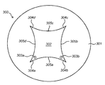
도 3a는 볼 발명에 따른 렌즈 안테나의 구현예의 사시도를 나타낸다.
도 3b는 평면도를 나타내고, 도 3c는 도 3a에 도시된 렌즈 안테나의 상세한 평면도를 나타낸다.
도 4는 본 발명에 따른 또 다른 렌즈 안테나의 구현예의 평면도를 나타낸다.
도 5는 본 발명에 따른 또 다른 렌즈 안테나의 구현예의 평면도를 나타낸다.
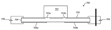
도 6 내지 도 9는 본 발명에 따른 다른 안테나 구조를 도식적으로 나타낸다.
도 10은 본 발명에 따른 다중 안테나를 포함하는 본 발명의 구현예에 따른 MIMO-구성 안테나 시스템을 나타낸다.The various illustrative embodiments of the invention will now be described on the basis of non-limiting exemplary embodiments shown in the following figures.
BRIEF DESCRIPTION OF THE DRAWINGS Figure 1 is a circuit diagram illustrating various components that may be included in various implementations for pattern analysis and / or pattern synthesis in a Super Formula Operator.
2 is a circuit diagram depicting steps or features that may be performed in an exemplary implementation involving synthesis of a pattern in a Super Formula Operator.
3A is a perspective view of an embodiment of a lens antenna according to the present invention.
FIG. 3B shows a plan view, and FIG. 3C shows a detailed plan view of the lens antenna shown in FIG. 3A.
4 shows a plan view of another embodiment of a lens antenna according to the present invention.
5 shows a plan view of another embodiment of a lens antenna according to the present invention.
Figs. 6 to 9 schematically show another antenna structure according to the present invention.
10 illustrates a MIMO-configured antenna system in accordance with an embodiment of the present invention including multiple antennas in accordance with the present invention.
제1 특징에 따르면, 도 1에서 언급된 예시의 목적을 위해, 이는 또한 US 7,620,527의 도 16에 포함되고, 본 발명에 따른 안테나의 접지면 및/또는 렌즈의 형상 또는 웨이브는 하기 예시적인 기본 단계들의 어플리케이션에 의해 "합성"될 수도 있다.According to a first aspect, for the purposes of the example mentioned in FIG. 1, it is also included in FIG. 16 of US 7,620,527, and the ground plane and / or the shape or wave of the lens of the antenna according to the present invention are shown in the following exemplary basic steps May be "synthesized"
제1 단계에서, 파라미터의 선택이 이루어지고(예를 들어 컴퓨터(10)로 값들이 입력되거나, 즉, 키보드(20), 터치 스크린, 마우스 포인터, 음성 인식장치, 또는 또 다른 입력 장치 또는 유사한 장치를 통해 입력되거나, 컴퓨터(10)가 값들을 설정하도록 함으로써), 컴퓨터(10)는 파라미터의 선택에 기초하여 선택된 초형상을 합성하기 위해 이용된다.In a first step, a selection of parameters is made (e.g., when values are input into the
제2 선택적 단계에서, 슈퍼포뮬러는 선택된 형상을 조정하고, 최적화를 계산하기 위해 이용될 수 있다. 이러한 단계는 그래픽 프로그램, CAD 소프트웨어, 유한 요소 분석 프로그램, 웨이브 생성 프로그램 또는 또 다른 소프트웨어의 이용을 포함할 수 있다. In a second optional step, the super-formula can be used to adjust the selected shape and calculate the optimization. These steps may include the use of graphics programs, CAD software, finite element analysis programs, wave generation programs or other software.
제3 단계에서, 제1 단계 또는 제2 단계로부터의 출력은 계산된 초형상을 물리적 형상으로 변환하기 위해 다음과 같은 단계를 통해 이용된다: (a) 모니터(30)에 초형상(31)을 표시하는 단계, (2D 또는 3D) 프린터(50)에서 종이와 같은 비축 물질(52)에 초형상(51)을 프린트하는 단계; (b) (제3 단계의 출력에 기초하여, 예를 들어, 기기 또는 로봇 등과 같은 외부 장치(60)를 제어함으로써) 컴퓨터 지원 제조를 수행하는 단계; (c) 스피커 시스템(70) 또는 유사한 장치를 통해 사운드(71)를 생성하는 단계; (d) 스테레오리소그라피를 수행하는 단계; (e) 3D 프린팅 기술에 기초하여 일반적으로 래피드 프로토타이핑을 수행하는 단계; 및/또는 (f) 이러한 형상으로 변환하기 위해 본 기술분야에 알려진 또 다른 방법으로 출력을 활용하는 단계.In a third step, the output from the first or second step is used through the following steps to convert the calculated seconds shape into a physical shape: (a) Printing a second shape (51) on a stock material (52) such as paper in a (2D or 3D) printer (50); (b) performing computer-aided manufacturing (e.g., by controlling an
다양한 컴퓨터 지원 제조(computer aided manufacturing, "CAM") 기술 및 그에 따라 제조된 생산품은 기술분야에서 알려져 있으며, 어떠한 적절한 CAM 기술 및 제조된 생산품이 선택될 수 있다. CAM 기술 및 그에 따라 제조된 생산품의 일부 예시로서, 하기 미국 특허(명칭은 괄호안)에 개시된 내용은 본원에 참조로서 삽입된다. 미국 특허 번호 5,796,986 (Method and apparatus for linking computer aided design databases with numerical control machine database); 미국 특허 번호 4,864,520 (Shape generating/creating system for computer aided design, computer aided manufacturing, computer aided engineering and computer applied technology); 미국 특허 번호 5,587,912 (Computer aided processing of three dimensional objects and apparatus therefor); 미국 특허 번호 5,880,962 (Computer aided processing of 3-D objects and apparatus thereof); 미국 특허 번호 5,159,512 (Construction of Minkowski sums and derivatives morphological combinations of arbitrary polyhedral in CAD/CAM systems).Various computer aided manufacturing ("CAM") technologies and products produced thereby are known in the art and any suitable CAM technology and manufactured product may be selected. As some examples of CAM technology and products made thereby, the disclosures of the following U. S. patents (named in parentheses) are incorporated herein by reference. U.S. Patent No. 5,796,986 (Method and apparatus for linking computer aided design databases with numerical control machine database); U.S. Patent No. 4,864,520 (Shape generating / creating system for computer aided design, computer aided manufacturing, computer aided engineering and computer applied technology); US Patent No. 5,587, 912 (Computer aided processing of three dimensional objects and apparatus therefor); U.S. Patent No. 5,880,962 (Computer aided processing of 3-D objects and apparatus thereof); U.S. Patent No. 5,159,512 (Construction of Minkowski sums and derivatives morphological combinations of arbitrary polyhedral in CAD / CAM systems).
다양한 스테레오리소그래피 기술 및 그에 따라 제조된 생산품은 기술분야에서 알려져 있으며, 어떠한 스테레오리소그래피 기술 및 제조된 생산품도 선택될 수 있다. 스테레오리소그래피 기술 및 그에 따라 제조된 생산품의 일부 예시로서, 하기 미국 특허(명칭은 괄호안)에 개시된 내용은 본원에 참조로서 삽입된다.: 미국 특허 번호 5,728,345 (Method for making an electrode for electrical discharge machining by use of a stereo lithography model); 미국 특허 번호 5,711,911 (Method of and apparatus for making a three-dimensional object by stereo lithography); 미국 특허 번호 5,639,413 (Methods and compositions related to stereo lithography); 미국 특허 번호 5,616,293 (Rapid making of a prototype part or mold using stereo lithography model); 미국 특허 번호 5,609,813 (Method of making a three-dimensional object by stereo lithography); 미국 특허 번호 5,609,812 (Method of making a three-dimensional object by stereo lithography); 미국 특허 번호 5,296,335 (Method for manufacturing fibre-reinforced parts utilizing stereo lithography tooling); 미국 특허 번호 5,256,340 (Method of making a three-dimensional object by stereo lithography); 미국 특허 번호 5,247,180 (Stereo lithographic apparatus and method of use); 미국 특허 번호 5,236,637 (Method of and apparatus for production of three dimensional objects by stereo lithography); 미국 특허 번호 5,217,653 (Method and apparatus for producing a stepless 3-dimensional object by stereo lithography); 미국 특허 번호 5,184,307 (Method and apparatus for production of high resolution three-dimensional objects by stereo lithography); 미국 특허 번호 5,182,715 (Rapid and accurate production of stereo lithographic parts); 미국 특허 번호 5,182,056 (Stereo lithography method and apparatus employing various penetration depths); 미국 특허 번호 5,182,055 (Method of making a three-dimensional object by stereo lithography); 미국 특허 번호 5,167,882 (Stereo lithography method); 미국 특허 번호 5,143,663 (Stereo lithography method and apparatus); 미국 특허 번호 5,130,064 (Method of making a three dimensional object by stereo lithography); 미국 특허 번호 5,059,021 (Apparatus and method for correcting for drift in production of objects by stereo lithography); 미국 특허 번호 4,942,001 (Method of forming a three-dimensional object by stereo lithography and composition therefore); 미국 특허 번호 4,844,144 (Investment casting utilizing 패턴s produced by stereo lithography).A variety of stereo lithography techniques and the resulting products are known in the art, and any stereolithography technique and manufactured product may be selected. As some examples of stereolithography techniques and products thus produced, the disclosure of the following US patents (names in parentheses) are incorporated herein by reference: US Pat. No. 5,728,345 (Method for making an electrode for electrical discharge machining use of a stereo lithography model); U.S. Patent No. 5,711,911 (Method and apparatus for making a three-dimensional object by stereo lithography); U.S. Patent No. 5,639,413 (Methods and compositions related to stereo lithography); U.S. Patent No. 5,616,293 (Rapid making of a prototype part or mold using stereo lithography model); U.S. Patent No. 5,609,813 (Method of making a three-dimensional object by stereo lithography); U.S. Patent No. 5,609,812 (Method of making a three-dimensional object by stereo lithography); U.S. Patent No. 5,296,335 (Method for manufacturing fiber-reinforced parts using stereo lithography tooling); U.S. Patent No. 5,256,340 (Method of making a three-dimensional object by stereo lithography); US Patent No. 5,247, 180 (Stereo lithographic apparatus and method of use); U. S. Patent No. 5,236, 637 (Method of apparatus for production of three dimensional objects by stereo lithography); U.S. Patent No. 5,217,653 (Method and apparatus for producing a stepless 3-dimensional object by stereo lithography); U.S. Patent No. 5,184,307 (Method and apparatus for high resolution three-dimensional objects by stereo lithography); U.S. Patent No. 5,182,715 (Rapid and accurate production of stereo lithographic parts); U.S. Patent No. 5,182,056 (Stereo lithography method and apparatus employing various penetration depths); U.S. Patent No. 5,182,055 (Method of making a three-dimensional object by stereo lithography); U.S. Patent No. 5,167,882 (Stereo lithography method); US Patent No. 5,143,663 (Stereo lithography method and apparatus); U.S. Patent No. 5,130,064 (Method of making a three dimensional object by stereo lithography); U.S. Patent No. 5,059,021 (Apparatus and method for correcting for drift in production of objects by stereo lithography); U.S. Patent No. 4,942,001 (Method of forming a three-dimensional object by stereo lithography and composition); U.S. Patent No. 4,844,144 (Investment casting using pattern s produced by stereo lithography).
게다가, 본 발명은 알려진 마이크로-스테레오리소그래픽 과정에서 이용될 수 있다. 예를 들어, 본 발명은, 따라서, 또 다른 아이템 및 컴퓨터 칩의 생성에 이용될 수 있다. 일부 예시가 되는 논문에 개시된 내용은 본원에 참조로서 삽입되며, 하기와 같다.: A. Bertsch, H Lorenz, P. Renaud "3D microfabrication by combining microstereolithography and thick resist UV lithography," Sensors and Actuators: A, 73, pp. 14-23, (1999). L. Beluze, A. Bertsch, P. Renaud "Microstereolithography: a new process to build complex 3D objects," Symposium on Design, Test and microfabrication of MEMs/MOEMs, Proceedings of SPIE, 3680(2), pp. 808-817, (1999). A. Bertsch, H. Lorenz, P. Renaud "Combining Microstereolithography and thick resist UV lithography for 3D microfabrication," Proceedings of the IEEE MEMS 98 Workshop, Heidelberg, Germany, pp. 18-23, (1998). A. Bertsch, J. Y. Jezequel, J. C. Andre "Study of the spatial resolution of a new 3D microfabrication process: the microstereophotolithography using a dynamic mask-generator technique," Journal of Photochem. and Photobiol. A: Chemistry, 107, pp. 275-281, (1997). A. Bertsch, S. Zissi, J. Y. Jezequel, S. Corbel, J. C. Andre "Microstereophotolithography using a liquid crystal display as dynamic mask-generator," Micro. Tech., 3(2), pp. 42-47, (1997). A. Bertsch, S. Zissi, M. Calin, S. Ballandras, A. Bourjault, D. Hauden, J. C. Ande "Conception and realization of miniaturized actuators fabricated by Microstereophotolithography and actuated by Shape Memory Alloys," Proceedings of the 3rd France-Japan Congress and 1st Europe-Asia Congress on Mechatronics, Besancon, 2, pp. 631-634, (1996).In addition, the present invention can be used in known micro-stereo lithographic processes. For example, the present invention can thus be used for the generation of other items and computer chips. The disclosure of some illustrative articles is incorporated herein by reference and is as follows: A. Bertsch, H. Lorenz, P. Renaud "3D microfabrication by combining microstereolithography and thick resist UV lithography, Sensors and Actuators: A, 73, pp. 14-23, (1999). L. Beluze, A. Bertsch, P. Renaud, "Microstereolithography: A new process to build complex 3D objects," Symposium on Design, MEMS / MOEMs, Proceedings of SPIE, 3680 (2), pp. 808-817, (1999). A. Bertsch, H. Lorenz, P. Renaud "Combining Microstereolithography and thick resist UV lithography for 3D microfabrication," Proceedings of the IEEE MEMS 98 Workshop, Heidelberg, Germany, pp. 18-23, (1998). A. Bertsch, J. Y. Jezequel, J. C. Andre "Study of the spatial resolution of a new 3D microfabrication process: a microstereophotolithography using a dynamic mask-generator technique, Journal of Photochem. and Photobiol. A: Chemistry, 107, pp. 275-281, (1997). A. Bertsch, S. Zissi, J. Y. Jezequel, S. Corbel, J. C. Andre "Microstereophotolithography using a liquid crystal display as a dynamic mask-generator," Micro. Tech., 3 (2), pp. 42-47, (1997). A. Bertsch, S. Zissi, M. Calin, S. Ballandras, A. Bourjault, D. Hauden, JC Ande "Conception and Realization of Miniaturized Actuators Fabricated by Microstereophotolithography and Actuated by Shape Memory Alloys," Proceedings of the Third France- Japan Congress and 1st Europe-Asia Congress on Mechatronics, Besancon, 2, pp. 631-634, (1996).
유사하게, 다양한 래피드 프로토타이핑 기술 및 그에 따라 제조된 생산품(예를 들어, 몰드 등)은 본 기술분야에서 알려져 있고, 어떠한 적절한 기술 및 제조된 생산품도 선택될 수 있다. 예를 들어, 현재 이용되는 3개의 예시적인 3차원 모델 래피드 프로토타이핑 방법은, 참조로서 삽입된 미국 특허 번호 5,578,227에서 설명된 바와 같이, a) 광경화성 액체 고형화 또는 스테레오리소그래피(상기에서 본) b) SLS(selective laser sintering) 또는 파우더 레이어 소결 기술; c) FDM(fused deposition modelling) 또는 or 압축 성형 플라스틱 증착 방법을 포함한다. 래피드 프로토타이핑 기술 및 그에 따라 제조된 생산품의 일부 예시로서, 하기 미국 특허(명칭은 괄호안)에 개시된 내용은 본원에 참조로서 삽입된다.: 미국 특허 번호 5,846,370 (Rapid prototyping process and apparatus therefor); 미국 특허 번호 5,818,718 (Higher order construction algorithm method for rapid prototyping); 미국 특허 번호 5,796,620 (Computerized system for lost foam casting process using rapid tooling set-up); 미국 특허 번호 5,663,883 (Rapid prototyping method); 미국 특허 번호 5,622,577 (Rapid prototyping process and cooling chamber therefor); 미국 특허 번호 5,587,913 (Method employing sequential two-dimensional geometry for producing shells for fabrication by a rapid prototyping system); 미국 특허 번호 5,578,227 (Rapid prototyping system); 미국 특허 번호 5,547,305 (Rapid, tool-less adjusting system for hot stick tooling); 미국 특허 번호 5,491,643 (Method for optimizing parameters characteristic of an object developed in a rapid prototyping system); 미국 특허 번호 5,458,825 (Utilization of blow molding tooling manufactured by stereo lithography for rapid container prototyping); 미국 특허 번호 5,398,193 (Method of three-dimensional rapid prototyping through controlled layerwise deposition/extraction and apparatus therefor).Similarly, a variety of rapid prototyping techniques and products made accordingly (e.g., molds, etc.) are known in the art and any suitable technology and manufactured product may be selected. For example, three exemplary three-dimensional model rapid prototyping methods currently in use include a) photocurable liquid solidification or stereolithography (as seen above) b) as described in US Pat. No. 5,578,227, incorporated by reference, SLS (selective laser sintering) or powder layer sintering technology; c) Fused deposition modeling (FDM) or compression molded plastic deposition methods. As part of the rapid prototyping technology and some of the products produced thereby, the disclosures of the following US patents (names in parentheses) are incorporated herein by reference: U.S. Patent No. 5,846,370 (Rapid prototyping process and apparatus therefor); U.S. Patent No. 5,818,718 (Higher order construction algorithm method for rapid prototyping); U.S. Patent No. 5,796,620 (Computerized system for lost foam casting process using rapid tooling set-up); U.S. Patent No. 5,663,883 (Rapid prototyping method); U.S. Patent No. 5,622,577 (Rapid prototyping process and cooling chamber therefor); U.S. Patent No. 5,587,913 (Method employing sequential two-dimensional geometry for producing shells for a rapid prototyping system); U.S. Patent No. 5,578,227 (Rapid prototyping system); U.S. Patent No. 5,547,305 (Rapid, tool-less adjusting system for hot stick tooling); U.S. Patent No. 5,491,643 (Method for optimizing parameters characteristic of an a rapid prototyping system); US Patent No. 5,458,825 (Utilization of blow molding tooling by stereo lithography for rapid container prototyping); U.S. Patent No. 5,398,193 (Method of three-dimensional rapid prototyping through controlled layerwise deposition / extraction and apparatus therefor).
상기 개시된 세개의 단계들 또는 특징은 또한 도 2(표시된 바와 같이 컴퓨터 자체에서 수행될 수 있는 1 단계 및 2 단계)에 나타난 회로도에서 도식적으로 설명된다. 본 도면은 미국 7,620,527의 도 17에 대응한다.The three steps or features disclosed above are also schematically illustrated in the circuit diagram shown in FIG. 2 (steps 1 and 2, which may be performed in the computer itself as indicated). This figure corresponds to FIG. 17 of US 7,620,527.
하기 섹션에서, 슈퍼포뮬러에서 패턴 "합성"의 다수의 예시적 구현예들이 보다 상세하게 설명된다.In the following section, a number of exemplary implementations of the pattern "composite" in the super formula are described in more detail.
A. 2-D 그래픽 소프트웨어A. 2-D graphics software
본 발명은 2-D 그래픽 소프트웨어 어플리케이션에서 매우 유용성을 갖는다. 본 발명은, 예를 들어, Corel-DrawTM 및 Corel-PaintTM, 개방 오피스 어플리케이션, 어도브 일러스트레이터를 위한 SupergraphxTM 및 PhotoshopTM, Adobe PhotoshopTM, Visual BasicTM 에서의 다양한 그리기 프로그램 또는 WindowsTM, 또는 예를 들어, Lotus WordProTM 및 Lotus Freelance GraphicsTM, JavaTM, Visual CTM, Visual C++TM 및 모든 또 다른 C-환경과 같은 또 다른 유사한 환경 등의 전형적인 상업적 프로그램에서 적용될 수 있다. 이미지 합성에 있어서 본 발명의 실질적 장점을 가지며, 또 다른 것들 사이에서, 본 접근이 고전적 함수(전력, 삼각함수 등과 같은)와 오직 슈퍼포뮬러를 이용하기를 요구하기 때문에 컴퓨터 메모리 공간의 실질적인 절감을 가능하게 하기 때문이다. 추가적으로 슈퍼포뮬러에서 가능한 이미지 형상의 개수는 이전에 가능한 것을 넘어 실질적으로 증가된다.The present invention is very useful in 2-D graphics software applications. The present invention can be applied to a variety of drawing programs or Windows TM , for example, Corel-Draw TM and Corel-Paint TM , open office applications, Supergraphx TM and Photoshop TM for Adobe Illustrator, Adobe Photoshop TM , Visual Basic TM , For example, it can be applied to typical commercial programs such as Lotus WordPro TM and Lotus Freelance Graphics TM , Java TM , Visual C TM , Visual C ++ TM, and any other similar environment such as all other C-environments. It has substantial advantages of the present invention in image synthesis, among other things, it allows substantial savings in computer memory space because this approach requires the use of classical functions (such as power, trigonometric functions, etc.) and only super- . In addition, the number of image features available in the super-formula is substantially increased beyond what was previously possible.
그래픽 프로그램(WindowsTM에서 그림판, Microsoft WordTM에서 그리기 도구, Corel-DrawTM, CAD, 또한 건축 설계에서 이용되는)은 컴퓨터에 프로그램된 형상인 "프리미티브"를 이용한다. 이것들은, 예를 들어, 종종 원형, 타원, 정사각형 및 직사각형에 주로 제한적이므로(3-D에서 용적형 프리미티브 또한 매우 제한적이다), 매우 제한적이다.Graphics programs (used in Paint on Windows TM , drawing tools in Microsoft Word TM , Corel-Draw TM , CAD, and also in architectural design) use a "primitive" shape that is programmed into the computer. These are very limited, for example, because they are often limited to circles, ellipses, squares, and rectangles (the volumetric primitives in 3-D are also very limited).
슈퍼포뮬러의 도입은 2-D 그래픽(및 또한 하기에서 논의될 3-D 그래픽)에서 전체 확률을 다수의 크기의 순서로 크게 확장한다. 선형 구동기로서 이용된 것은 많은 다른 방법 및 포뮬레이션(formulations), 극 좌표 등에서 동작할 수 있다. 또한, 구면 좌표, 원통 좌표, 균질화된 원통의 파라미터적 포뮬레이션 등을 이용하는 3-D에서 동작할 수 있다.The introduction of the super-formula greatly expands the overall probability in order of magnitude in 2-D graphics (and also 3-D graphics, discussed below). What is used as a linear driver can operate in many different ways and formulations, polar coordinates, and the like. It can also operate in 3-D using spherical coordinates, cylindrical coordinates, parametric formulation of homogenized cylinders, and so on.
2-D 그래픽 소프트웨어 어플리케이션에서 일부 예시적인 구현예는 하기와 같다.Some exemplary implementations in a 2-D graphics software application are as follows.
a.1. 예를 들어, 극 좌표 또는 XY 좌표에서, 컴퓨터는 오퍼레이터의 분명한 이용을 생성하기 위해 조정될 수 있다. 이러한 경우, 파라미터는 선택될 수 있으며(예를 들어, 오퍼레이터 입력에 의해 또는 컴퓨터 자체에 의해), 슈퍼포뮬러의 입력으로서 이용될 수 있다(예를 들어 프로그래밍을 통해). 개별적인 형상 또는 오브젝트는 오브젝트를 프린트하거나 디스플레이 하는 등과 같이, 여러 경우에서든 이용될 수 있다.a.1. For example, in polar or XY coordinates, the computer can be adjusted to create an obvious use of the operator. In this case, the parameters can be selected (e.g., by operator input or by the computer itself) and used as inputs to the super formula (e.g., via programming). Individual shapes or objects can be used in many instances, such as printing or displaying objects.
a.2. 컴퓨터는 또한 면적, 주변둘레, 관성모멘트 등을 계산하기 위한 적분과 같은 연산을 수행하도록 조정될 수 있다. 이와 관련하여, 컴퓨터는 a) 오퍼레이터 입력(예를 들어 키보드(20)를 통해)을 통한 이와 같은 연산의 선택, 또는 b) 이와 같은 연산을 수행하기 위해 컴퓨터의 조정(예를 들어, 프리-프로그래밍을 통해)과 같은 연산을 수행하도록 조정될 수 있다. a.2. The computer can also be tuned to perform operations such as integration to calculate area, perimeter circumference, moment of inertia, and the like. In this regard, the computer may either: a) select such an operation through an operator input (e.g., via the keyboard 20), or b) adjust the computer (e.g., (E.g., via the < / RTI >
a.3. 컴퓨터는 (소프트웨어를 통해) a) 형상을 디스플레이하거나 또는 다른 방법으로 표시하거나 b) 사용자가 그것을 디스플레이한 후 이러한 형상을 수정하도록 허용하거나 c) 사용자에 의해 수정된 형상을 디스플레이 하도록 조정될 수 있다. 이와 관련하여, 사용자는 예를 들어, 파라미터를 변경함으로써 형상을 수정할 수 있다. 예시적인 구현예에서, 컴퓨터는 3 단계에서 생성된 물리적 표현에서 물리적으로 동작함에 따라 형상이 디스플레이되거나 또는 다른 방법으로 표시되는 것(예를 들어, 상기 3 단계에서 표시된)이 가능하도록 조정될 수 있다. 바람직한 구현예에서, 컴퓨터는 패턴(예를 들어, 이미지)의 코너 및/또는 측면을 빠져나가도록 함으로써 수정되기 위해 형상이 모니터에 디스플레이되도록 조정될 수 있다. 이와 관련하여, 바람직하게는, 이미지(31)는 컴퓨터 스크린 또는 모니터(30)에 디스플레이되고, 사용자는 새로운 위치(33)와 동일하게 "클릭" 및 "드래그"를 하기 위해 형상에 디스플레이된 포인터(32)를 위치하고 그의 손 조작 "마우스"(40)(또는 또 다른 사용자-조작 스크린 또는 디스플레이 포인터 장치)를 이용할 수 있고, 따라서 새로운 "초형상" 배치(34)를 추정하기 위해 상기 초형상을 조정한다. 이는 파라미터 및 공식의 재계산을 또한 포함할 것이다. a.3. The computer can be adjusted (via software) to display a) the shape or otherwise display, b) allow the user to modify the shape after displaying it, or c) display the shape modified by the user. In this regard, the user can modify the shape, for example, by changing the parameters. In an exemplary implementation, the computer may be adjusted to allow the shape to be displayed or otherwise displayed (e.g., as indicated in step 3) as it physically operates in the physical representation created in step 3. In a preferred embodiment, the computer can be adjusted to display a shape on the monitor to be modified by allowing it to escape the corners and / or sides of the pattern (e.g., image). In this regard, preferably, the
a.4. 컴퓨터는 또한 슈퍼-포지션(super-position)의 과정을 통해, a1 또는 a3에서 생성된 하나 이상의 개별적인 형상이 함께 하는 동작을 수행하도록 조정될 수 있다. 일부 경우에서, 예를 들어, 슈퍼-포지션 및/또는 반복 또는 유사한 것에 의해 결합된 개별적인 초형상들은 예를 들어, 다른 섹션 또는 영역을 갖는 형상을 생성하기 위해 조합가능한 섹터 또는 섹션일 수 있다(설명적인 예시로서, 예를 들어 0과 π/2 사이에 원의 섹터는 예를 들어 π/2와 π 사이에 정사각형의 섹터와 조합되어, 다중-구성요소 형상을 생성할 수 있음) 컴퓨터는 또한 생성된 초형상을, 예를 들어, 납작하게 하거나, 왜곡하거나, 길어지게 하거나, 확대시키거나, 회전시키거나, 움직이거나 또는 옮기거나, 또는 이러한 형상을 다른 방법으로 수정하는 것과 같이, 추가적인 동작을 수행하도록 조정될 수 있다. a.4. The computer can also be tuned to perform an action with one or more of the individual shapes generated in a1 or a3 through the course of a super-position. In some cases, for example, individual superimpositions combined by superposition and / or by repetition or the like can be a combinable sector or section to create a shape having, for example, another section or region As an example, a sector of origin between 0 and pi / 2 may be combined with a square sector, for example between pi / 2 and pi, to produce a multi-component geometry) Additional operations are performed, such as flattening, distorting, lengthening, enlarging, rotating, moving, or moving, or modifying such shapes in other ways .
B. 3-D 그래픽 소프트웨어B. 3-D graphics software
2-D 어플리케이션과 마찬가지로, 본 발명은 3-D 그래픽 소프트웨어 어플리케이션(다양한 또 다른 차원에서 표현에서도)에서 매우 유용성을 갖는다. Like the 2-D application, the present invention is very useful in 3-D graphics software applications (even in various other dimensions).
본 발명은 예를 들어, CAD(Computer Aided Design) 소프트웨어, FEM(Finite Element Analysis)을 위한 소프트웨어, Supergraphx 3D Shape Explorer, 예를 들어, CST, Ansoft HFSS, Remcom XFdtd, EMSS Feko, Empire XCcel, 건축 디자인 소프트웨어 등과 같은 안테나 디자인 및 분석 소프트웨어에서 적용될 수 있다. 본 발명은, 다양한 어플리케이션을 위해, 예를 들어, 스플라인(spline) 함수보다 단일 연속 함수를 이용하도록 허용한다. CAD의 산업적 어플리케이션은 예를 들어, 3D 프린팅을 포함하는 컴퓨터 지원 제조("CAM") 또는 래피드 프로토타이핑에서 이용을 포함한다.For example, the present invention can be applied to computer aided design (CAD) software, software for Finite Element Analysis (FEM), Supergraphx 3D Shape Explorer such as CST, Ansoft HFSS, Remcom XFdtd, EMSS Feko, Empire XCcel, ≪ / RTI > software, and the like. The present invention allows for a single continuous function to be used, for example, for a variety of applications, rather than a spline function. Industrial applications of CAD include, for example, use in computer-aided manufacturing ("CAM") or rapid prototyping, including 3D printing.
도 3a을 참조하면, 본 발명의 바람직한 구현예에 따른 렌즈 안테나(300)의 구현예가 표시된다. 안테나(300)는 접지면(301), 상기 접지면(301)에 탑재된 전자기 렌즈(302), 및 두 개의 프로브(303a, 303b)를 포함하는 프로빙 구조체를 포함한다. 렌즈(302)는 슈퍼포물러를 따르는 각기둥 형상을 갖는다. 실시예에서 상기 렌즈(302)는 PVC로 만들어진다. 렌즈(302)에는 프로브를 수용하기 위한 수용 공간(304)이 제공된다. 접지면(301)은 금속으로 만들어진다. 두 개의 프로브들(303a) 및 접지면(301)은 일반적으로 제어 회로(미도시)를 통해, 배터리(DC) 또는 주전원(AC)과 같은 전기 전원에 연결된다. 상기 구현예에서 렌즈(302)는 렌즈 안테나(300)를 유전체 공진기 안테나(dielectric resonator antenna, DRA)로 만드는 유전체 공진기로서 동작한다. 렌즈(302)는 슈퍼포뮬러를 따르기 때문에, 상기 안테나(300) 또한 초형상 안테나(supershaped antenna, S-DRA)로서 고려될 수 있다. 접지면(301)으로서 동작하는 원형 금속판은 반경 평면을 갖는다. 안테나(300)는 동축커넥터 터닝(turning)에 의해서 바닥 측으로부터 높이 ![]()
![]()
![]()
![]()
![]()
![]()
![]()
![]()

여기서 ![]()
![]()
![]()
![]()
폴리머릭 렌즈(302)에는 두 개의 수용 공간이 제공되고, 각각 잘 맞는 방식으로 단일 프로브(303a, 303b)를 수용하도록 구성된 것이다. 프로브(303a, 303b)가 서로의 시선의 외부에 위치되는 결과로서(쇄선 참조), 상기 수용 공간 및 따라서 프로브(303a, 303b)는 렌즈(302)의 다른 에지(304a, 304b)에 또는 근접하여 위치되고, 이는 도 3a 및 도 3b에 또한 나타난다. 표시된 바와 같이, 앞서언급된 4개의 코너(304a, 304b, 304c, 304d)가 정의되는 결과로서, 원주방향 벽(305)은 서로 연결된 4개의 오목한 벽 부분(305a, 305b, 305c, 305d)을 포함한다. 오목한 벽 부분들 중 하나(305a)에는 선택적으로 주름진 프로파일이 제공된다. 프로브(303a, 303b)에 의해 여기된 전자기 방사선은, 또 다른 프로브(303b, 303a)로부터 멀어지는 방향에서, 벽 부분(305a, 305b, 305c, 305d), 특히 중간 주름진 벽부분(305a)에 의해 반사될 것이며(화살표 참조), 따라서 상호 커플링 및 간섭이 상쇄될 수 있다.The
상기 설명적인 실시예에서 렌즈(302)에 이용된 PVC는 프로세싱의 용이성 및 낮은 비용을 이유로 대량 생산된 열가소성 폴리머이다. 또한, PVC는 화학적 부식에 저항력이 있고, 강한 내구성이 있으므로, 야외 어플리케이션에 매우 잘 적응한다. 추가적으로, PVC는 넓은 범위의 물리적 성질을 제공하는 다른 물질들과 섞일 수 있다. PVC의 이용은, 전형적인 드릴링/밀링(drilling/milling) 또는 더 진보된 3차원 프린팅 기술을 이용함으로써, 복잡한 형상의 유전체 공진기/렌즈 안테나를 제조하기 위한 비싸지 않은 선택을 도출할 수 있다. 더욱이, 이는 주거 단지, 사무실 빌딩, 극장, 경기장 등과 같은 거주가능한 구조에서의 무선 통신에 이용되는 경우, 제안된 방사 구조의 심미적 질을 강화하기 위해 상당한 중요성이 있다. PVC는 복잡한 공진기/렌즈 지오메트리의 구현을 가능하게 할 뿐 아니라, 이것의 낮은 유전율로 인해, 안테나 퀄리티 팩터(quality factor)를 감소시키고, 따라서 동작 주파수 대역을 확장시키고, 에너지방사선 레벨 또한 강화시킨다. 제안된 방사기는 프랙셔널(fractional) 대역폭 및 이득이라는 두가지 면에서 고전적인 유전체 공진기/렌즈 안테나를 능가한다. 플라스틱 물질의 이용 덕분에, 이러한 성능은 감소된 제조 비용으로 성취될 수 있다. 상기 특징은 차세대 무선 멀티미디어 어플리케이션을 대표하는 대량-생산 컨텍스트(contexts)에서 특히 바람직하다. 구체적인 어플리케이션에 맞춰, 안테나의 단일 생산을 위해 3D 프린팅을 이용하는 것 또한 가능하다. 일반적으로 3D 프린팅에서 3-차원 고체 오브젝트는 첨가물 과정을 이용하여 형성되며, 이는 원하는 것을 생성하기 위해 물질의 연속적인 레이어들이 또 다른 위에 내려놓아진 것이다. 대량 생산 및 3D 프린팅에서, 물질의 유전체 상수에 따라, 바이오플라스틱 및 플라스틱의 조합을 포함하는 다양한 플라스틱이 이용될 수 있다. The PVC used in the
레이더, 위성 및 무선 통신을 위한 안테나 제조는 재생이 어렵고 생산 과정에서 높은 이산화탄소 배출 레벨에 의해 상당한 환경적 영향을 주는 비싼 마이크로웨이브 물질을 이용하는 것을 일반적으로 수반한다. 반면, 제안된 플라스틱 및 특히 PVC(폴리비닐 클로라이드)의 이용은, 초형상 유전체 공진기 및 렌즈의 제조를 위해, 지속가능성이라는 면에서 명확한 장점을 제공한다. 사실상, PVC는 재생하기 저적한 물질이며, 대부분 염소로부터 생성되기 때문에 적은 천연자원을 요구하며, 이는 지구에 충분한 일반적인 소금으로부터 추출된다. 따라서, 또 다른 플라스틱과는 반대로, PVC는 비-재생 자원인 석유를 절감하는데 중요하게 기여한다. 게다가 PVC는 오직 또 다른 폴리머를 생산하는데 요구되는 에너지의 약 80%를 요구한다. 따라서, 대체가능한 저-탄소 물질은, 친환경 효과를 가지면서도 회로 특성 및 방사선 성질이라는 점에서 좋은 장치 성능을 유지하는 초형상 유전체 공진기/렌즈 안테나의 제조에 유용하게 채용될 수 있다는 것이 강조된다. Manufacture of antennas for radar, satellite and radio communications generally involves the use of expensive microwave materials which are difficult to regenerate and which have significant environmental impact due to their high carbon dioxide emission levels during production. On the other hand, the use of the proposed plastics and in particular PVC (polyvinyl chloride) provides clear advantages in terms of sustainability, for the production of superficial dielectric resonators and lenses. In fact, PVC is an extremely low-regenerating material, and it is often produced from chlorine, requiring little natural resources, which are extracted from enough common salt on Earth. Thus, contrary to other plastics, PVC is an important contributor to the reduction of non-renewable resources. In addition, PVC requires only about 80% of the energy required to produce another polymer. It is thus emphasized that replaceable low-carbon materials can be usefully employed in the manufacture of super-geometry dielectric resonator / lens antennas that maintain good device performance in terms of circuit and radiation properties while having an eco-friendly effect.
또한, 또 다른 구현예에서, 다양한 또 다른 물질들이 높은 지속가능한 방법으로 안테나를 생선하는데 채용될 수 있다. 게다가 동적 형상의 안테나는 구체적인 목표에 따라 이것의 동작을 수정하기 위해 변하고, 액체 구성요소(예컨대, 액체 크리스탈)를 이용하는 것이 채용될 수 있으며, 기계적 또는 전기적 스티어링(steering)에 의해, 또는 또 다른 물리적 힘의 이용에 의해 수정된 형상 변화의 동적성을 수반한다.Also, in yet another embodiment, a variety of other materials may be employed to fish the antenna in a highly sustainable manner. In addition, the dynamic shaped antenna may be modified to modify its operation according to specific goals, and it may be employed to use a liquid component (e.g., a liquid crystal) and may be applied by mechanical or electrical steering, It involves the dynamics of the shape changes modified by the use of force.
도 4는 본 발명의 구현예에 따른 렌즈 안테나(400)의 평면도를 나타내고, 도 3a 내지 도 3c에 나타난 안테나(300)와 더 유사거나 덜 유사한다. 안테나(400)는 접지면(401), 상기 접지면(401)에 탑재된 전자기 렌즈(402) 및 두 개의 프로브(403a, 403b)를 포함하는 프로빙 구조체를 포함한다. 렌즈(402)는 슈퍼포뮬러를 따르는 각기둥 형상이고, 원주방향 벽(404)는 4개의 오목한 원주방향 벽 부분(404a, 404b, 404c, 404d)에 의해 형성되고, 근접한 벽 부분(404a, 404b, 404c, 404d)은 렌즈(402)의 샤프 에지(405a, 405b, 405c, 405d)를 상호 형성한다. 프로브(403a, 403b)는 렌즈(402)의 다른 샤프 에지(405a, 405b)에 위치되고, 프로브(403a, 403b) 사이에 실질적으로 위치한 원주방향 벽 부분(404a)의 오목한 형상으로 인해, 프로브(403a, 403b)는 전자기 관점에서 서로를 보지 않는다. 직접적인 시선(LOS)은 수평 쇄선 LOS로 대략 지시된다. 또한, 중간 벽 부분(404a)에는 프로파일 표면이 제공되므로, 프로브(403a, 403b)에 의해 전송된 전자기 방사선은 또 다른 프로브(403a, 403b)로부터 멀어지도록 반사될 것이고(화살표 참조), 상호 커플링은 감소할 것이고, 따라서 렌즈 안테나(400) 사이에서 간섭은 감소할 것이고, 안테나(400)의 효율 및 용량에 도움이될 것이다. 상기 설명적 구현예에서, 상호 커플링은 또한 분리된 반사 구성요소(406)(거울)의 존재에 의해 감소된다. 이러한 반사 구성요소(406)은 금속판에 의해 형성될 수 있고, 렌즈 바디(402)에 포함되고, 반사 구성요소(406)에 도달하는 전자기 방사선이 다시 반사되어 돌아오도록 양 측이 반사적이며, 또한 각각 다른 프로브(403a, 403b)에 의해 전송된 방사 패턴의 간섭이 감소할 수 있다. 실시예에서 상기 렌즈(402)는 PVC로 만들어진다. 상기 접지면(401)은 금속으로 만들어진다. 두 개의 프로브(403a, 403b) 및 접지면(402)은 일반적으로 제어 회로(도시하지 않음)를 통해, 배터리(DC) 또는 주전원(AC)과 같은 전기 전원에 연결된다. 상기 구현예에서 렌즈(402)는 렌즈 안테나(400)를 유전체 공진기 안테나(dielectric resonator antenna, DRA)로 만드는 유전체 공진기로서 동작한다. 렌즈(402)는 슈퍼포뮬러를 따르기 때문에, 상기 안테나(400) 또한 초형상 안테나(supershaped antenna, S-DRA)로서 고려될 수 있다. 상기 프로브(403a, 403b)는 동일한 지오메트리를 가질 수도 있고, 다른 지오메트리를 가질 수도 있다.Figure 4 shows a top view of a
도 5는 본 발명에 따른 렌즈 안테나(500)의 또 다른 구현예의 평면도를 나타낸다. 렌즈 안테나는 금속 접지면(501), 상기 금속 접지면(501)에 탑재된 전자기 렌즈(502), 및 5개의 프로브(503a, 503b, 503c, 503d, 503e)를 포함하는 프로빙 구조체를 포함한다. 상기 렌즈(502)는 각기둥 형상을 가지며, 앞서언급된 슈퍼포뮬러에 따른 별 모양의 베이스 프로파일(502a)을 가진다. 프로브들(503a, 503b, 503c, 503d, 503e)은 각각 렌즈(502)의 다른 각도(에지 또는 코너)에 각각 위치된다. 이러한 방식으로, 다른 프로브들(503a, 503b, 503c, 503d, 503e)은 실질적으로 서로 보지 않을 것이고, 따라서 서로 간섭하지 않을 것이다. 다른 프로브들(503a, 503b, 503c, 503d, 503e)은 예를 들어 Wi-Fi 통신 시스템 또는 또 다른 통신 시스템에서 다중대역 동작에 적합한 안테나(500)를 만들기 위해 다른 지오메트리를 가질 수 있다.5 shows a plan view of another embodiment of a
도 6은 상호 구별되는 지오메트리를 갖는 두 개의 다른 프로브(602, 603)를 둘러싸는 초형상 렌즈(601)를 포함하는 듀얼-대역 안테나(600)를 나타내며, 상기 프로브(602, 603)는 서로의 시야의 라인의 외부에 위치된다. 상기 렌즈(601) 및 프로브들(602, 603)은 편평한 접지면(604)에 연결된다. 일부 실시예에서, 편평한 접지면(604) 대신, 커브형 또는 다른 형상의 접지면(604)이 이용될 수 있다. 각각의 프로브들(602, 603)은 상기 접지면(604)에 또한 연결된 커넥터인 동축 커넥터(605, 605)로부터 확장된다. 상기 렌즈(601)는 일부 실시예에서 실리콘으로 만들어진다. 일부 실시예에서, 가장 짧은 프로브(602)는 2.4 GHz의 주파수 대역에서 동작하도록 구성되고, 가장 긴 프로브(603)는 5 GHz의 주파수 대역에서 동작하도록 구성되며, 이것은 상기 소형 안테나(600)가 듀얼-대역 Wi-Fi-안테나로서 적절한 역할을 하도록 한다.6 shows a dual-
도 7은 렌즈(701), 및 상기 렌즈(701)에 연결된 반사 초형상 접지면(702)을 포함하는 듀얼-대역 안테나(700)를 나타내고, 여기서 접지면(702)에는 2개의 중심 홀(hole)(703a, 703b)이 제공되고, 각 홀(703a, 703b)는 접지면(702)이 부착되는 유전체 PCB(printed circuit Board, 704) 및 렌즈(701) 사이의 공간 또는 슬롯을 형성한다. 홀들(703a, 703b)은 서로의 시야의 라인의 외부에 적어도 부분적으로 위치된다. PCB(704)의 뒷면에는 두 개의 전기적으로 전도성인 마이크로스트립(705a, 705b)이 제공된다. 접지면(702) 및 각 마이크로스트립(705a, 705b)을 배터리(706)와 같은 전원, 및 일반적으로 제어 유닛 및 스위치를 포함하는 전자 회로(706)(도식적으로 나타난)에 연결함으로써, 고정된 평면파면(static planar wave front)이 각각의 마이크로스트립(705a, 706b) 및 접지면(702) 사이에 형성될 것이고, 파면은 각 홀(703a, 703b)을 통해 렌즈(701)로 진입할 것이고, 렌즈(701)에서 구형 파면으로 변환될 것이다. 렌즈(701)에서 전자기 방사선은 내부적으로 반사될 것이고, 제어된 방법으로 여기(excited)될 것이고, 렌즈(701)의 (초)형상에 의존할 것이고, 결국 접지면(702)의 초형상에 의존할 것이다. 이러한 매커니즘은 슬롯 급전 안테나라고 한다.7 shows a dual-
도 8은 초형상 렌즈(801)를 포함하는 단일-대역 안테나(800)를 나타내고, 렌즈(801)는 절연층(802)의 라미네이이트 및, 접지면으로서 동작하는 전기적 전도층(803)에 연결된다. 전기적 전도층(803)은 두 개의 프로브(805a, 805b)가 통과하는 중심 홀(804)이 제공된다. 각 프로브(805a, 805b)의 외부 끝은, 렌즈(801) 내에 위치하면서 렌즈(801)의 안 및/또는 밖으로 전자기를 커플링하도록 구성된, 유사한 지오메트리의 전도성 패치(806a, 806b)에 연결된다. 프로브들(805a, 805b)은 또한 프로세서를 포함하는 제어 회로(807)에 연결된다. 프로브들(805a, 805b) 및 전기적 전도층(803)은 AC 전원(808)D에 연결된다. 제어 회로(807)는, 사용자가 안테나(800)의 목적(신호 전송, 신호 수신, 또는 둘 다) 및 안테나(800)에 의해 이용되는 주파수 대역과 같은 안테나(800)의 특성을 정의하도록 허용하는 컴퓨터 인터페이스(809)를 이용하여 프로그램되도록 구성된다.8 shows a single-
도 9는 초형상 유전체 공진기(901)를 포함하는 다중-대역 안테나(900)를 나타내고, 공진기(901)는 제1 절연층(902)의 라미네이트, 접지면으로서 동작하는 전기적 전도층(903), 제2 절연층(904) 및 2개의 마이크로스트립(905a, 905b)에 연결된다. 일부 구현예에서, 공진기(901)는 PVC 또는 Teflon®또는 세라믹 및 폴리머의 조합물/혼합물로 만들어진다. 공진기(901) 내부이자 제1 절연층(902) 위에, 전기적 전도성 패치(906a, 906b)가 제공된다. 패치(906a, 906b)는 편평한 지오메트리 또는 초형상 지오메트리를 가질 수 있다. 접지면(903)은 금속 및/또는 전기적 전도성 폴리머로 만들어지고, 접지면에는 두 개의 홀(907a, 907b)이 제공되며, 각 마이크로스트립(905a, 905b)은 외부 끝이 상기 패치(906a, 906b) 중 어느 하나에 따라 위치될 것으로 확장한다. 마이크로스트립(905a, 905b) 및 (중간) 접지면(903)을 전원(908)에 연결함에 따라, 전자기 평면파면은 마이크로스트립(905a, 905b) 및 접지면(903) 사이에 형성될 것이고, 이것은 두개의 구형 파면이 상기 렌즈로 전파되는 방식으로 패치(906)를 여기(excite)할 것이다. 패치들(906)은 파면들이 서로 간섭하지 않는 방식으로 렌즈 바디(901) 내에 위치한다. 안테나(900)는 라우터, 노트북, 모바일 폰과 같은 전자 장치(909)의 일부를 생성할 수 있다.9 shows a
도 10은 본 발명에 따른 다중 안테나들(1001, 1002)를 포함하는 본 발명의 일부 구현예에 따른 MIMO-구성 안테나 시스템(1000)을 나타내고, 여기서 안테나(1001, 1002)는 두 방향에서 서로 무선으로 통신하도록 구성된다. 제1 안테나(1001)는 다중 프로브들(1003, 1004, 1005)를 포함하고, 두 개의 프로브(1003, 1004)는 동일한 지오메트리를 가지며, 동일한 제1 주파수 대역에서 동작하도록 구성되며, 반면 또 다른 안테나(1005)는 다른 지오메트리를 가지며 또 다른 제2 주파수 대역에서 동작하도록 구성된다. 프로브(1003, 1004, 1005)는 접지판(1007)에 의해 지지되는 초형상 렌즈(1006)에 의해 둘러싸인다. 프로브는 제어 회로(미도시)에 연결된 동축 커넥터(1008, 1009, 1010)의 일부를 생성한다. 이용은 두 개의 동일한 프로브(1003, 1004)로 만들어지고, 통신을 강화하여 제1 안테나(1001)의 신뢰도를 높이기 위해서 이들은 각각으로부터 충분한 거리에 상호적으로 위치한다. 또 다른 안테나(1002)는 두 개의 프로브(1011, 1012)를 포함하고, 제1 프로브(1011)은 제1 주파수 대역에서 동작하도록 구성되고, 또 다른 프로브(1012)는 제2 주파수 대역에서 동작하도록 구성된다. 프로브(1011, 1012)는 접지판(접지면)(1014)에 의해 지지되는 초형상 렌즈(103)에 의해 둘러싸인다. 프로브는 제어 회로(미도시)에 연결된 동축 커넥터(1015, 1016)의 일부를 생성한다.10 illustrates a MIMO-configured
본 발명은 본 명세서에 기재되고 보여진 예시적인 구현예들로 한정되는 것이 아니며, 첨부된 특허청구범위의 범주 내에서 다수의 변형예들이 본 기술분야의 통상의 기술자에게 자명하게 가능할 수 있다는 점은 명백하다. 또한, 본 발명은 다수의 발명적 장치, 구성요소, 측면, 방법 등을 포함한 다수의 구현예들을 갖는다는 점이 본 명세서의 개시내용에 기초하여 인식되어야 한다. 본 명세서에서, "본 발명"이라는 언급은 본 발명의 모든 구현예들에 대해 적용하려는 의도는 아니다.It is to be understood that the invention is not to be limited to the exemplary embodiments shown and described herein and that many modifications within the scope of the appended claims may be made apparent to one of ordinary skill in the art Do. Furthermore, it should be appreciated that the present invention has numerous implementations, including a number of inventive devices, components, aspects, methods, and so on, based on the teachings of the present disclosure. In the present specification, the term " present invention "is not intended to be applied to all embodiments of the present invention.
본 요약은 본 개시내용 내에서 확장된 논의내용에서 제공된 시사점들에 대해 다수의 시사 및 변형의 완전한 리스트가 아닌 본 명세서에 개시된 개념들의 도입부를 제공하는 것으로 여겨진다. 따라서, 본 요약의 내용은 첨부된 특허청구범위의 범주를 제한하는데 사용되어서는 안 된다.This Summary is believed to provide an introduction to the concepts disclosed herein rather than a complete list of numerous suggestions and variations on the teachings provided in the discussion that has been extended within the present disclosure. Accordingly, the content of this summary should not be used to limit the scope of the appended claims.
발명적 개념들은 일련의 실시예들에서 예시되며, 일부 실시예들은 하나의 발명적 개념 그 이상을 나타낸다. 개별적 발명적 개념들은 특정 실시예에서 제공되는 상세내용을 모두 구현하지 않은채 수행될 수 있다. 본 기술분야의 통상의 기술자라면 다양한 실시예들에서 예시되는 발명적 개념들이 특이적 적용을 유도하도록 함께 조합될 수 있다는 점을 인식할 것이기 때문에, 제공되는 발명적 개념들의 가능한 모든 조합의 실시예들을 제공하는 것은 필요하지 않다.The inventive concepts are illustrated in a series of embodiments, wherein some embodiments represent more than one inventive concept. Individual inventive concepts may be implemented without implementing all of the details provided in the specific embodiments. As one of ordinary skill in the art will appreciate that the inventive concepts illustrated in the various embodiments may be combined together to lead to a specific application, It is not necessary to provide.
개시된 내용의 다른 시스템들, 방법들, 특징들 및 이점들은 본 기술분야의 통상의 기술자에게 명백하거나 또는 도면과 상세한 설명의 검토를 통해 본 기술분야의 통상의 기술자에게 명백해질 것이다. 이와 같은 모든 부가적 시스템들, 방법들, 특징들 및 이점들은 첨부되는 특허청구범위의 범주 및 그에 의해 보호되는 범주 내에 포함되는 것으로 의도된다.Other systems, methods, features, and advantages of the disclosed subject matter will be or become apparent to one of ordinary skill in the art or will be apparent to one of ordinary skill in the art upon review of the drawings and detailed description. All such additional systems, methods, features, and advantages are intended to be included within the scope of the appended claims and the protected scope thereby.
청구항들의 제한사항들(예컨대, 나중에 추가되는 것들을 포함함)은 청구항에서 이용되는 언어에 기초하여 넓게 해석되어야 하며, 본 출원을 진행하는 동안 또는 본 명세서에 기재된 실시예들로 한정되지 않으며, 이러한 실시예들은 배타적인 것으로서 구성되지 않는다. 예를 들어, 본 명세서의 개시내용에서, "바람직하게는"이라는 용어는 배타적이지 않으며, "바람직하게는, 그러나 여기에 한정되지 않는"을 의미한다. 본 명세서의 개시내용에서 그리고 본 출원을 진행하는 동안, 기능식 청구항의 한정요소들(means-plus-function or step-plus-function limitations)은 a) "를 위한 수단(means for)" 또는 "를 위한 단계(step for)"가 분명하게 인용되고; b) 대응하는 기능이 분명하게 인용되고; c) 그 구조를 뒷받침하는 구조, 물질 또는 작용이 인용되어 있지 않은; 조건들의 모든 한정요소가 특정 청구항에 존재할 때에만 이용될 것이다. 본 명세서의 개시내용에서 그리고 본 출원을 진행하는 동안, 용어 "본 발명" 또는 "발명"은 본 명세서의 개시내용 내에서 하나 이상의 측면에 관한 것으로서 사용될 수 있다. 용어 본 발명 또는 발명은 임계의 지표로서 부적절하게 해석되어서는 안 되며, 모든 특징들 또는 구현예들을 가로질러 적용하는 것으로서 부적절하게 해석되어서는 안 되며(즉, 본 발명은 다수의 특징들과 구현예들을 갖는 것으로 이해되어서는 안 됨), 본 출원 또는 청구항의 범위를 제한하는 것으로서 부적절하게 해석되어서는 안 된다. 본 명세서의 개시내용에서 그리고 본 출원을 진행하는 동안, 용어 "구현예"는 임의의 양상, 특징, 과정 또는 단계, 이들의 임의의 조합, 및/또는 이들의 임의의 부분 등을 기재하기 위해 사용될 수 있다. 일부 실시예에서, 다양한 구현예들은 중첩되는 특징들을 포함할 수 있다. 본 명세서의 개시내용에서, "예를 들어"를 의미하는 "과 같은, 예컨대"와 같은 용어들이 이용될 수 있다.It should be understood that the limitations of the claims (including, for example, those added later) should be construed broadly based on the language used in the claims, and not limited to the embodiments described herein or during the course of this application, Examples are not to be construed as exclusive. For example, in the present disclosure, the term "preferably" is not exclusive and means "preferably, but not limited to. &Quot; In the present disclosure and during the course of the present application, means-plus-function or step-plus-function limitations are defined as a) "means for" or " Quot; step for "is clearly cited; b) the corresponding function is explicitly cited; c) the structure, material or action supporting the structure is not cited; And will be used only when all the limiting elements of the conditions are present in the particular claim. While in the disclosure of this specification and throughout this application, the term " present invention "or" invention "may be used as relating to one or more aspects within the context of this disclosure. TERMINOLOGY The present invention or invention should not be improperly interpreted as an indicator of criticality and should not be improperly interpreted as applying across all features or implementations (i.e., And should not be construed as being unduly misinterpreted as limiting the scope of the present application or the claims. The use of the term "embodiment" to describe any aspect, feature, process or step, any combination of these, and / or any portion thereof, etc. in the context of the present disclosure and throughout this application . In some embodiments, various implementations may include overlapping features. In the present disclosure, terms such as " such as, for example, "and the like may be used.
Claims (65)
- 상기 렌즈에 연결된 하나 이상의 접지면; 및
- 상기 렌즈에 연결된 하나 이상의 프로빙(probing) 구조체;를 포함하되,
상기 프로빙 구조체는 둘 이상의 프로브를 포함하고,
상기 프로브가 렌즈에 의해 둘러싸이고,
둘 이상의 프로브가 상호 지향하는 방향은, 상기 프로브가 적어도 부분적으로 서로의 전자기 시선의 외부에 위치되도록 마련되고, 상기 전자기 시선은 상기 프로브가 전자기 시점으로부터 서로 볼 수 없도록 방해를 받는 것을 특징으로 하는 안테나.At least one electromagnetic lens;
At least one ground plane connected to the lens; And
- at least one probing structure connected to the lens,
Wherein the probing structure comprises two or more probes,
Wherein the probe is surrounded by a lens,
Characterized in that the direction in which the two or more probes are oriented towards each other is such that the probes are at least partially located outside of each other's electromagnetic line of sight and the electromagnetic lines are disturbed such that the probes can not see each other from the electromagnetic viewpoint .
상기 프로브 사이에서 하나 이상의 반사 구성요소는 하나 이상의 프로브에 의해 전송되는 전자기 방사선을 하나 이상의 다른 프로브로부터 멀어지게 반사하도록 위치되는 것을 특징으로 하는 안테나.The method according to claim 1,
Wherein the at least one reflective component between the probes is positioned to reflect the electromagnetic radiation transmitted by the at least one probe away from the at least one other probe.
하나 이상의 반사 구성요소는 상기 프로브 사이의 일직선이 상기 하나 이상의 반사 구성요소에 의해 방해되도록 위치되는 것을 특징으로 하는 안테나. 3. The method of claim 2,
Wherein the at least one reflective component is positioned such that a straight line between the probes is obstructed by the at least one reflective component.
하나 이상의 반사 구성요소는 상기 렌즈의 원주방향 벽에 의해 형성되는 것을 특징으로 하는 안테나.3. The method of claim 2,
Wherein the at least one reflective component is formed by a circumferential wall of the lens.
상기 렌즈의 하나 이상의 원주방향 벽의 적어도 일부가 오목한 형상인 것을 특징으로 하는 안테나.5. The method of claim 4,
Wherein at least a portion of at least one circumferential wall of the lens is concave.
상기 원주방향 벽의 적어도 일부가 주름진 것을 특징으로 하는 안테나.5. The method of claim 4,
Wherein at least a portion of the circumferential wall is corrugated.
하나 이상의 안테나 프로브는 상기 렌즈의 샤프 에지(sharp edge)에 위치하거나 가까이 위치하는 것을 특징으로 하는 안테나.The method according to claim 1,
Wherein the at least one antenna probe is located at or near a sharp edge of the lens.
상기 프로빙 구조체는 전자기 방사선을 수신하도록 구성되는 것을 특징으로 하는 안테나.The method according to claim 1,
Wherein the probing structure is configured to receive electromagnetic radiation.
상기 프로빙 구조체는 전자기 방사선을 전송하도록 구성되는 것을 특징으로 하는 안테나.The method according to claim 1,
Wherein the probing structure is configured to transmit electromagnetic radiation.
둘 이상의 프로브의 지오메트리는 상호간에 다른 것을 특징으로 하는 안테나.The method according to claim 1,
Wherein the geometries of the two or more probes are mutually different.
상기 둘 이상의 프로브 중 하나 이상은 5 GHz 주파수 대역에서 동작하도록 구성되고, 상기 프로브의 길이는 4 내지 8mm인 것을 특징으로 하는 안테나.The method according to claim 1,
Wherein at least one of the at least two probes is configured to operate in a frequency band of 5 GHz and the length of the probe is between 4 and 8 mm.
상기 둘 이상의 프로브 중 하나 이상은 2.4 GHz 주파수 대역에서 동작하도록 구성되고, 상기 프로브의 길이는 10 내지 18mm인 것을 특징으로 하는 안테나.The method according to claim 1,
Wherein at least one of the at least two probes is configured to operate in a frequency band of 2.4 GHz, and the length of the probe is between 10 and 18 mm.
상기 둘 이상의 프로브 중 하나 이상의 직경은 1 내지 3mm인 것을 특징으로 하는 안테나.The method according to claim 1,
Wherein the diameter of at least one of the at least two probes is 1 to 3 mm.
상기 렌즈에는 상기 프로빙 구조체의 프로브를 수용하기 위한 하나 이상의 수용 공간이 제공되는 것을 특징으로 하는 안테나.The method according to claim 1,
Wherein the lens is provided with at least one receiving space for receiving a probe of the probing structure.
상기 접지면에는 상기 프로빙 구조체의 프로브를 수용하기 위한 하나 이상의 수용 공간이 제공되는 것을 특징으로 하는 안테나.The method according to claim 1,
Wherein the ground plane is provided with at least one receiving space for receiving a probe of the probing structure.
상기 안테나는 다중 수용 공간들을 포함하고, 각 수용 공간은 단일 프로브를 수용하도록 구성되는 것을 특징으로 하는 안테나.The method according to claim 1,
Wherein the antenna comprises multiple receiving spaces and each receiving space is configured to receive a single probe.
둘 이상의 상기 다중 수용 공간의 상호 지향은 수용 공간이 서로의 전자기 시선의 외부에 위치되도록 하는 것을 특징으로 하는 안테나.17. The method of claim 16,
Wherein the mutual directing of the two or more of the multiple accommodation spaces allows the accommodation spaces to be located outside of the electromagnetic lines of sight of each other.
상기 렌즈의 높이는 5 cm 이하인 것을 특징으로 하는 안테나.The method according to claim 1,
Wherein the height of the lens is 5 cm or less.
상기 렌즈는 적어도 부분적으로 유전체 물질로 만들어진 것을 특징으로 하는 안테나.The method according to claim 1,
Wherein the lens is at least partially made of a dielectric material.
상기 렌즈는 하나 이상의 세라믹으로 적어도 부분적으로 만들어진 것을 특징으로 하는 안테나.20. The method of claim 19,
Wherein the lens is at least partially made of one or more ceramics.
상기 렌즈는 유리, 크리스탈 또는 하나 이상의 폴리머로 적어도 부분적으로 만들어진 것을 특징으로 하는 안테나.20. The method of claim 19,
Wherein the lens is at least partially made of glass, crystal or one or more polymers.
상기 렌즈는 유체로 적어도 부분적으로 채워진 하나 이상의 내부 공간을 둘러싸는 하나 이상의 유리, 크리스탈 또는 하나 이상의 폴리머로 적어도 부분적으로 만들어진 쉘을 포함하는 것을 특징으로 하는 안테나.22. The method of claim 21,
Wherein the lens comprises a shell that is at least partially made of one or more glasses, crystals, or one or more polymers that surround one or more interior spaces that are at least partially filled with a fluid.
상기 렌즈는 유전체 공진기인 것을 특징으로 하는 안테나.The method according to claim 1,
Wherein the lens is a dielectric resonator.
상기 하나 이상의 접지면 및 상기 하나 이상의 전자기 렌즈 중 하나 이상은 슈퍼포뮬러로 초형상화(supershaped)되는 하나 이상의 베이스 프로파일을 갖고, 상기 베이스 프로파일은 슈퍼포뮬러인 하기 극함수에 의해 정의되는 것을 특징으로 하는 안테나:

여기서,
-
-
- m은 회전 대칭 파라미터이고, n은 지수 파라미터이고, a와 b는 짧은 축 및 긴 축의 파라미터임.The method according to claim 1,
Characterized in that at least one of the at least one ground plane and at least one of the at least one electromagnetic lens has at least one base profile that is supershaped into a super formula and wherein the base profile is defined by a hyper- :
here,
-
-
- m is the rotational symmetry parameter, n is the exponential parameter, and a and b are the parameters of the short axis and the long axis.
상기 렌즈 또는 상기 접지면의 3차원 형상의 파라미터적 표현은 두 개의 수직 크로스 섹션들

여기서,
-
-
-
- x, y 및 z는 3차원 좌표이고,
The parametric representation of the three-dimensional shape of the lens or of the ground plane may comprise two vertical cross-
here,
-
-
-
- x, y and z are three-dimensional coordinates,
m ≥ 4인 것을 특징으로 하는 안테나.25. The method of claim 24,
m > = 4.
a≠b인 것을 특징으로 하는 안테나.25. The method of claim 24,
and a &bull; b.
nx, ny 및 n0의 하나 이상의 값은 2에서 벗어나는 것을 특징으로 하는 안테나.25. The method of claim 24,
and wherein at least one value of n x , n y and n 0 deviates from 2.
초형상화된 상기 베이스 프로파일은 상기 접지면에 의해 정의된 평면에 평행한 방향으로 확장되는 렌즈의 베이스 프로파일인 것을 특징으로 하는 안테나.25. The method of claim 24,
Wherein the superimposed base profile is a base profile of a lens extending in a direction parallel to a plane defined by the ground plane.
상기 렌즈 또는 상기 접지면은 프리즘 형상인 것을 특징으로 하는 안테나.The method according to claim 1,
Wherein the lens or the ground plane has a prism shape.
상기 렌즈로 지향하는 상기 접지면의 표면은 적어도 부분적으로 반사면인 것을 특징으로 하는 안테나.The method according to claim 1,
Wherein the surface of the ground plane facing the lens is at least partially a reflective surface.
상기 접지면은 적어도 부분적으로 전기적 전도성 물질로 만들어진 것을 특징으로 하는 안테나. The method according to claim 1,
Wherein the ground plane is at least partially made of an electrically conductive material.
상기 프로빙 구조체는 상기 접지면에 연결되는 것을 특징으로 하는 안테나.The method according to claim 1,
Wherein the probing structure is connected to the ground plane.
상기 렌즈는 굴절률 n을 가지며, 이때 n≠1인 것을 특징으로 하는 안테나.The method according to claim 1,
Wherein the lens has a refractive index n, wherein n < RTI ID = 0.0 ># 1. ≪ / RTI >
상기 프로빙 구조체는 제1 주파수 대역에서 통신하기 위해 구성된 하나 이상의 제1 프로브, 및 제2 주파수 대역에서 통신하기 위해 구성된 하나 이상의 제2 프로브를 포함하는 것을 특징으로 하는 안테나.The method according to claim 1,
Wherein the probing structure comprises at least one first probe configured to communicate in a first frequency band and at least one second probe configured to communicate in a second frequency band.
상기 프로빙 구조체는 다중 제1 프로브들 및 다중 제2 프로브들을 포함하는 것을 특징으로 하는 안테나.36. The method of claim 35,
Wherein the probing structure comprises multiple first probes and multiple second probes.
상기 안테나는 상기 프로빙 구조체의 양-방향 통신을 위해 방사선 전송 모드 및 방사선 수신 모드 사이에서 상기 프로빙 구조체를 자동적으로 스위치하는 하나 이상의 프로세서를 포함하는 것을 특징으로 하는 안테나.36. The method of claim 35,
Wherein the antenna comprises one or more processors that automatically switch the probing structure between a radiation transmission mode and a radiation reception mode for bi-directional communication of the probing structure.
상기 프로세서는 각 주파수 대역에서 양-방향 통신을 위해 제1 주파수 대역 및 제2 주파수 대역 사이에서 자동적으로 스위치하도록 구성되는 것을 특징으로 하는 안테나. 39. The method of claim 37,
Wherein the processor is configured to automatically switch between a first frequency band and a second frequency band for bi-directional communication in each frequency band.
모든 프로브가 상호 지향하는 방향은, 모든 프로브가 적어도 부분적으로 서로의 전자기 시선의 외부에 위치하도록 마련된 것을 특징으로 하는 안테나.The method according to claim 1,
Wherein the directions in which all of the probes are mutually oriented are arranged such that all of the probes are located at least partially outside the electromagnetic lines of each other.
복수의 MIMO-구성 안테나를 포함하고, 상기 복수의 MIMO-구성 안테나는 상기 프로빙 구조체가 제1 주파수 대역에서 통신하기 위해 구성된 하나 이상의 제1 프로브, 및 제2 주파수 대역에서 통신하기 위해 구성된 하나 이상의 제2 프로브를 포함하도록 마련된 것을 특징으로 하는 안테나 시스템. 41. The method of claim 40,
Wherein the plurality of MIMO-configured antennas comprises at least one first probe configured to communicate at a first frequency band and at least one first probe configured to communicate at a second frequency band, 2 < / RTI > probe.
상기 시스템은 둘 이상의 듀얼-대역 안테나, 및 두 개의 주파수 대역 중 하나 이상에서 스위칭을 위한 하나 이상의 프로세서를 포함함으로써, 상기 주파수 대역에서 신호의 전송 및 수신의 다양성을 보장하는 안테나 시스템.42. The method of claim 41,
The system includes at least two dual-band antennas, and at least one processor for switching at one or more of the two frequency bands, thereby ensuring diversity of signal transmission and reception in the frequency bands.
접지면, 렌즈, 및 다중 프로브들을 포함하는 프로빙 구조체를 조립하는 단계를 포함하되, 둘 이상의 프로브가 상호 지향하는 방향은, 상기 프로브가 적어도 부분적으로 서로의 전자기 시선의 외부에 위치하도록 마련되고, 상기 전자기 시선은 상기 프로브가 전자기 시점으로부터 서로 볼 수 없도록 방해를 받는 것을 특징으로 하는 제조방법.40. A method of manufacturing an antenna according to any one of claims 1 to 39,
Comprising the steps of: assembling a probing structure comprising a ground plane, a lens, and multiple probes, wherein the direction in which two or more probes are mutually directed is provided such that the probes are located at least partially outside of the respective electromagnetic lines of sight, Wherein the electromagnetic line of sight is interrupted so that the probe can not see each other from the electromagnetic viewpoint.
하나 이상의 접지면 또는 하나 이상의 렌즈는 상기 접지면 또는 상기 렌즈가 하나 이상의 베이스 프로파일을 가지도록 설계되고, 상기 베이스 프로파일은 슈퍼포뮬러인 하기 극함수에 의해 정의되는 것을 특징으로 하는 제조방법:

여기서,
-
-
- m은 회전 대칭 파라미터이고, n은 지수 파라미터이고, a와 b는 짧은 축 및 긴 축의 파라미터임.44. The method of claim 43,
Wherein the at least one ground plane or at least one lens is designed such that the ground plane or the lens has at least one base profile and wherein the base profile is defined by a super-
here,
-
-
- m is the rotational symmetry parameter, n is the exponential parameter, and a and b are the parameters of the short axis and the long axis.
조립하는 단계에서 다중 프로브들은 상기 접지면 또는 상기 렌즈에 연결되는 것을 특징으로 하는 제조방법.44. The method of claim 43,
Wherein the plurality of probes are connected to the ground plane or the lens in the assembling step.
하나 이상의 프로브는 제1 주파수 대역에서 통신하기 위해 구성되고, 하나 이상의 다른 프로브는 제2 주파수 대역에서 통신하기 위해 구성되는 것을 특징으로 하는 제조방법.46. The method of claim 45,
Wherein one or more probes are configured to communicate in a first frequency band and one or more other probes are configured to communicate in a second frequency band.
상이한 프로브들이, 동작하는 동안 상기 렌즈의 다른 섹터가 여기(excited)되도록 지향되는 것을 특징으로 하는 제조방법.47. The method of claim 46,
Wherein different probes are directed such that different sectors of the lens are excited during operation.
상기 렌즈는 크리스탈, 유리, 세라믹, 폴리머 및 탈염수로 이루어진 군으로부터 선택된 유전체 물질로 적어도 부분적으로 만들어지는 것을 특징으로 하는 제조방법.44. The method of claim 43,
Wherein the lens is at least partially made of a dielectric material selected from the group consisting of crystal, glass, ceramic, polymer and demineralized water.
폴리머로 만들어지는 상기 렌즈는 3D 프린팅에 의해 만들어지는 것을 특징으로 하는 제조방법.49. The method of claim 48,
Wherein the lens made of polymer is made by 3D printing.
안테나 네트워크에 통신 회로를 연결하는 단계를 포함하되, 상기 네트워크는 상기 안테나를 복수 포함하고, 각 안테나는 하나 이상의 지정된 주파수 대역에서 동작하도록 마련된 것을 특징으로 하는 방법. 39. A method for use in a wireless communication using an antenna according to any one of claims 1 to 39,
Connecting a communication circuit to an antenna network, the network comprising a plurality of the antennas, each antenna being arranged to operate in one or more designated frequency bands.
각 안테나는 다중 주파수 대역에서 동작하도록 마련된 것을 특징으로 하는 방법.51. The method of claim 50,
Each antenna being arranged to operate in multiple frequency bands.
복수의 지정된 주파수 대역 각각은 단일 주파수를 포함하는 것을 특징으로 하는 방법.51. The method of claim 50,
Wherein each of the plurality of designated frequency bands comprises a single frequency.
Applications Claiming Priority (3)
| Application Number | Priority Date | Filing Date | Title |
|---|---|---|---|
| US201261705117P | 2012-09-24 | 2012-09-24 | |
| US61/705,117 | 2012-09-24 | ||
| PCT/NL2013/050195 WO2014046538A1 (en) | 2012-09-24 | 2013-03-15 | Lens antenna, method of manufacturing and using such an antenna, and antenna system |
Publications (2)
| Publication Number | Publication Date |
|---|---|
| KR20150063481A KR20150063481A (en) | 2015-06-09 |
| KR101697033B1 true KR101697033B1 (en) | 2017-01-16 |
Family
ID=47997741
Family Applications (2)
| Application Number | Title | Priority Date | Filing Date |
|---|---|---|---|
| KR1020157010808A KR101697032B1 (en) | 2012-09-24 | 2013-03-15 | Lens antenna, method of manufacturing and using such an antenna, and antenna system |
| KR1020157010812A KR101697033B1 (en) | 2012-09-24 | 2013-03-15 | Lens antenna, method of manufacturing and using such an antenna, and antenna system |
Family Applications Before (1)
| Application Number | Title | Priority Date | Filing Date |
|---|---|---|---|
| KR1020157010808A KR101697032B1 (en) | 2012-09-24 | 2013-03-15 | Lens antenna, method of manufacturing and using such an antenna, and antenna system |
Country Status (12)
| Country | Link |
|---|---|
| US (2) | US9831562B2 (en) |
| EP (4) | EP3062395A1 (en) |
| JP (2) | JP6001180B2 (en) |
| KR (2) | KR101697032B1 (en) |
| CN (2) | CN104781987A (en) |
| AU (2) | AU2013318709A1 (en) |
| BR (2) | BR112015006447A2 (en) |
| CA (2) | CA2885954A1 (en) |
| IL (2) | IL237850A0 (en) |
| RU (2) | RU2622467C2 (en) |
| WO (2) | WO2014046538A1 (en) |
| ZA (2) | ZA201502543B (en) |
Cited By (1)
| Publication number | Priority date | Publication date | Assignee | Title |
|---|---|---|---|---|
| KR101894840B1 (en) | 2017-09-15 | 2018-09-04 | 세종대학교산학협력단 | Rf lens and antenna including the same |
Families Citing this family (59)
| Publication number | Priority date | Publication date | Assignee | Title |
|---|---|---|---|---|
| US10197508B2 (en) | 2014-07-07 | 2019-02-05 | Univeristy Of Manitoba | Imaging using reconfigurable antennas |
| US10468778B2 (en) | 2014-09-24 | 2019-11-05 | The Antenna Company International N.V. | Blade antenna and wireless local area network comprising a blade antenna |
| US10547118B2 (en) * | 2015-01-27 | 2020-01-28 | Huawei Technologies Co., Ltd. | Dielectric resonator antenna arrays |
| CN104953281B (en) * | 2015-05-27 | 2017-07-11 | 华中科技大学 | A kind of medium resonator antenna of frequency-adjustable |
| US10355361B2 (en) | 2015-10-28 | 2019-07-16 | Rogers Corporation | Dielectric resonator antenna and method of making the same |
| US10601137B2 (en) | 2015-10-28 | 2020-03-24 | Rogers Corporation | Broadband multiple layer dielectric resonator antenna and method of making the same |
| US10374315B2 (en) | 2015-10-28 | 2019-08-06 | Rogers Corporation | Broadband multiple layer dielectric resonator antenna and method of making the same |
| US10476164B2 (en) | 2015-10-28 | 2019-11-12 | Rogers Corporation | Broadband multiple layer dielectric resonator antenna and method of making the same |
| US11367959B2 (en) | 2015-10-28 | 2022-06-21 | Rogers Corporation | Broadband multiple layer dielectric resonator antenna and method of making the same |
| KR20170112715A (en) * | 2016-04-01 | 2017-10-12 | 삼성전자주식회사 | Antenna and electronic device having it |
| CN106058447B (en) * | 2016-05-16 | 2019-02-15 | 电子科技大学 | A kind of broadband and wide wave beam circularly polarized dielectric resonator antenna suitable for X-band |
| TWI629835B (en) * | 2016-07-21 | 2018-07-11 | 和碩聯合科技股份有限公司 | Antenna unit, antenna system and antenna control method |
| CN112886216B (en) * | 2016-10-21 | 2024-02-13 | 株式会社友华 | Vehicle-mounted antenna device and antenna system |
| US10116051B2 (en) * | 2017-03-17 | 2018-10-30 | Isotropic Systems Ltd. | Lens antenna system |
| US11876295B2 (en) * | 2017-05-02 | 2024-01-16 | Rogers Corporation | Electromagnetic reflector for use in a dielectric resonator antenna system |
| US11283189B2 (en) | 2017-05-02 | 2022-03-22 | Rogers Corporation | Connected dielectric resonator antenna array and method of making the same |
| DE112018002940T5 (en) | 2017-06-07 | 2020-02-20 | Rogers Corporation | Dielectric resonator antenna system |
| CN110691690B (en) * | 2017-06-09 | 2023-01-03 | 依视路国际公司 | Method and system for manufacturing an optical lens with electronic components |
| US10923818B2 (en) * | 2017-09-21 | 2021-02-16 | City University Of Hong Kong | Dual-fed dual-frequency hollow dielectric antenna |
| US10587034B2 (en) * | 2017-09-29 | 2020-03-10 | Commscope Technologies Llc | Base station antennas with lenses for reducing upwardly-directed radiation |
| US20220190464A1 (en) * | 2017-10-06 | 2022-06-16 | At&S Austria Technologie & Systemtechnik Aktiengesellschaft | Component Carrier Having at Least a Part Formed as a Three-Dimensionally Printed Structure Forming an Antenna |
| US20190115668A1 (en) * | 2017-10-13 | 2019-04-18 | ETS-Lindgren Inc. | Rf lens and method of manufacture |
| RU2681276C1 (en) * | 2017-12-19 | 2019-03-05 | Закрытое акционерное общество "Научно-производственное предприятие оборудования систем телекоммуникаций" | Panel antenna |
| JP6633604B2 (en) * | 2017-12-21 | 2020-01-22 | アンリツ株式会社 | Antenna measurement system and antenna measurement method |
| US10892544B2 (en) | 2018-01-15 | 2021-01-12 | Rogers Corporation | Dielectric resonator antenna having first and second dielectric portions |
| US11616302B2 (en) | 2018-01-15 | 2023-03-28 | Rogers Corporation | Dielectric resonator antenna having first and second dielectric portions |
| US10910722B2 (en) | 2018-01-15 | 2021-02-02 | Rogers Corporation | Dielectric resonator antenna having first and second dielectric portions |
| KR102104483B1 (en) * | 2018-01-30 | 2020-04-24 | 한국과학기술원 | Pattern configurable dielectric resonator antenna |
| WO2019169343A1 (en) * | 2018-03-02 | 2019-09-06 | Optisys, LLC | Mass customization of antenna assemblies using metal additive manufacturing |
| CN108933334B (en) * | 2018-07-19 | 2021-04-02 | 华北水利水电大学 | Method and device for manufacturing spherical Longbo electromagnetic lens reflector |
| US11552390B2 (en) | 2018-09-11 | 2023-01-10 | Rogers Corporation | Dielectric resonator antenna system |
| US11031697B2 (en) | 2018-11-29 | 2021-06-08 | Rogers Corporation | Electromagnetic device |
| GB2594171A (en) | 2018-12-04 | 2021-10-20 | Rogers Corp | Dielectric electromagnetic structure and method of making the same |
| CN111509403B (en) * | 2019-01-31 | 2022-02-18 | Oppo广东移动通信有限公司 | Array antenna and electronic device |
| US10886619B2 (en) | 2019-02-28 | 2021-01-05 | Apple Inc. | Electronic devices with dielectric resonator antennas |
| US10886617B2 (en) | 2019-02-28 | 2021-01-05 | Apple Inc. | Electronic devices with probe-fed dielectric resonator antennas |
| EP3918362B1 (en) | 2019-04-04 | 2024-10-23 | Siemens Industry Software NV | A method for computer-implemented simulation of radar raw data |
| US10833415B2 (en) | 2019-04-11 | 2020-11-10 | The Boeing Company | Radio frequency circuit board with microstrip-to-waveguide transition |
| RU2715914C1 (en) * | 2019-05-29 | 2020-03-04 | Федеральное Государственное Бюджетное Образовательное Учреждение Высшего Образования "Новосибирский Государственный Технический Университет" | Method of determining the surface of a dielectric bifocal lens antenna |
| US10903540B2 (en) | 2019-05-31 | 2021-01-26 | Nokia Solutions And Networks Oy | Dual-mode corrugated waveguide cavity filter |
| EP3758148A1 (en) | 2019-06-25 | 2020-12-30 | Nokia Solutions and Networks Oy | An antenna having controlled directivity |
| CN110414164B (en) * | 2019-08-01 | 2020-12-08 | 西安电子科技大学 | 6G communication antenna channel capacity prediction method based on electromechanical coupling |
| CN110707432B (en) * | 2019-09-18 | 2021-01-08 | 佛山市粤海信通讯有限公司 | Foaming medium material and production method thereof |
| US11239566B2 (en) * | 2019-09-26 | 2022-02-01 | Corning Incorporated | Fresnel phase lenses for 5G applications |
| KR102090767B1 (en) * | 2019-10-04 | 2020-05-26 | (주)디 넷 | Radar module apparatus for sensor |
| US11550062B2 (en) * | 2019-12-24 | 2023-01-10 | All.Space Networks Ltd. | High-gain multibeam GNSS antenna |
| CN110783713B (en) * | 2019-12-31 | 2020-11-24 | 佛山市粤海信通讯有限公司 | Electromagnetic wave lens, antenna and antenna array |
| US11482790B2 (en) | 2020-04-08 | 2022-10-25 | Rogers Corporation | Dielectric lens and electromagnetic device with same |
| US11177548B1 (en) | 2020-05-04 | 2021-11-16 | The Boeing Company | Electromagnetic wave concentration |
| CN111613879B (en) * | 2020-06-09 | 2021-09-21 | 四川大学 | Dielectric non-resonant antenna |
| US11967781B2 (en) * | 2020-09-23 | 2024-04-23 | Apple Inc. | Electronic devices having compact dielectric resonator antennas |
| CN114389018B (en) * | 2020-10-22 | 2023-01-31 | 展讯通信(上海)有限公司 | Patch antenna unit and packaged antenna array |
| CN112272146A (en) * | 2020-11-12 | 2021-01-26 | 佛山蓝谱达科技有限公司 | Millimeter wave router with high wireless transmission rate |
| US12119554B2 (en) | 2021-05-14 | 2024-10-15 | Optisys, Inc. | Planar monolithic combiner and multiplexer for antenna arrays |
| RU2770237C1 (en) * | 2021-09-03 | 2022-04-14 | федеральное государственное автономное образовательное учреждение высшего образования «Московский физико-технический институт (национальный исследовательский университет)» | Transceiver device and method for its manufacture |
| JP7482100B2 (en) * | 2021-12-09 | 2024-05-13 | キヤノン株式会社 | Radiation detection equipment |
| CN114566800A (en) * | 2022-02-14 | 2022-05-31 | 中山大学 | MIMO dielectric resonator antenna based on directional diagram decoupling |
| US11936112B1 (en) * | 2022-05-05 | 2024-03-19 | Lockheed Martin Corporation | Aperture antenna structures with concurrent transmit and receive |
| WO2024191567A1 (en) * | 2023-03-15 | 2024-09-19 | Outdoor Wireless Networks LLC | Lensed sector-splitting multiband base station antennas where the number of beams per frequency band is not related by the frequency ratio between the frequency bands |
Citations (3)
| Publication number | Priority date | Publication date | Assignee | Title |
|---|---|---|---|---|
| WO2005093905A1 (en) | 2004-03-26 | 2005-10-06 | Bae Systems Plc | An antenna with partially spherical dielectric lenses |
| US20100220031A1 (en) | 2006-12-04 | 2010-09-02 | Agc Automotive Americas R&D, Inc. | Wideband dielectric antenna |
| WO2011161548A2 (en) | 2010-06-21 | 2011-12-29 | Johan Gielis | Computer implemented tool box systems and methods |
Family Cites Families (42)
| Publication number | Priority date | Publication date | Assignee | Title |
|---|---|---|---|---|
| JPS6074003A (en) | 1983-09-30 | 1985-04-26 | Ryozo Setoguchi | Shape creating device |
| US5236637A (en) | 1984-08-08 | 1993-08-17 | 3D Systems, Inc. | Method of and apparatus for production of three dimensional objects by stereolithography |
| US4942001A (en) | 1988-03-02 | 1990-07-17 | Inc. DeSoto | Method of forming a three-dimensional object by stereolithography and composition therefore |
| US5182056A (en) | 1988-04-18 | 1993-01-26 | 3D Systems, Inc. | Stereolithography method and apparatus employing various penetration depths |
| US5182055A (en) | 1988-04-18 | 1993-01-26 | 3D Systems, Inc. | Method of making a three-dimensional object by stereolithography |
| US5130064A (en) | 1988-04-18 | 1992-07-14 | 3D Systems, Inc. | Method of making a three dimensional object by stereolithography |
| US5059359A (en) | 1988-04-18 | 1991-10-22 | 3 D Systems, Inc. | Methods and apparatus for production of three-dimensional objects by stereolithography |
| US5184307A (en) | 1988-04-18 | 1993-02-02 | 3D Systems, Inc. | Method and apparatus for production of high resolution three-dimensional objects by stereolithography |
| US5256340A (en) | 1988-04-18 | 1993-10-26 | 3D Systems, Inc. | Method of making a three-dimensional object by stereolithography |
| US5711911A (en) | 1988-04-18 | 1998-01-27 | 3D Systems, Inc. | Method of and apparatus for making a three-dimensional object by stereolithography |
| US4844144A (en) | 1988-08-08 | 1989-07-04 | Desoto, Inc. | Investment casting utilizing patterns produced by stereolithography |
| US5143663A (en) | 1989-06-12 | 1992-09-01 | 3D Systems, Inc. | Stereolithography method and apparatus |
| EP0405106A3 (en) | 1989-06-16 | 1992-04-08 | International Business Machines Corporation | Construction of minkowski sums and derivative morphological combinations of arbitrary polyhedra in cad/cam systems |
| US5182715A (en) | 1989-10-27 | 1993-01-26 | 3D Systems, Inc. | Rapid and accurate production of stereolighographic parts |
| US5167882A (en) | 1990-12-21 | 1992-12-01 | Loctite Corporation | Stereolithography method |
| US5217653A (en) | 1991-02-18 | 1993-06-08 | Leonid Mashinsky | Method and apparatus for producing a stepless 3-dimensional object by stereolithography |
| US5247180A (en) | 1991-12-30 | 1993-09-21 | Texas Instruments Incorporated | Stereolithographic apparatus and method of use |
| JP2558431B2 (en) | 1993-01-15 | 1996-11-27 | ストラタシイス,インコーポレイテッド | Method for operating system for manufacturing three-dimensional structure and apparatus for manufacturing three-dimensional structure |
| US5296335A (en) | 1993-02-22 | 1994-03-22 | E-Systems, Inc. | Method for manufacturing fiber-reinforced parts utilizing stereolithography tooling |
| SE501411C2 (en) | 1993-07-12 | 1995-02-06 | Nobelpharma Ab | Method and apparatus for three-dimensional body useful in the human body |
| US5458825A (en) | 1993-08-12 | 1995-10-17 | Hoover Universal, Inc. | Utilization of blow molding tooling manufactured by sterolithography for rapid container prototyping |
| US5398193B1 (en) | 1993-08-20 | 1997-09-16 | Alfredo O Deangelis | Method of three-dimensional rapid prototyping through controlled layerwise deposition/extraction and apparatus therefor |
| US5491643A (en) | 1994-02-04 | 1996-02-13 | Stratasys, Inc. | Method for optimizing parameters characteristic of an object developed in a rapid prototyping system |
| US5796620A (en) | 1995-02-03 | 1998-08-18 | Cleveland Advanced Manufacturing Program | Computerized system for lost foam casting process using rapid tooling set-up |
| US5547305A (en) | 1995-03-02 | 1996-08-20 | The Whitaker Corporation | Rapid, tool-less adjusting system for hotstick tooling |
| US5728345A (en) | 1995-03-03 | 1998-03-17 | General Motors Corporation | Method for making an electrode for electrical discharge machining by use of a stereolithography model |
| US5616293A (en) | 1995-03-03 | 1997-04-01 | General Motors Corporation | Rapid making of a prototype part or mold using stereolithography model |
| US5639413A (en) | 1995-03-30 | 1997-06-17 | Crivello; James Vincent | Methods and compositions related to stereolithography |
| WO1996036921A1 (en) | 1995-05-19 | 1996-11-21 | 3Com Corporation | Method and apparatus for linking computer aided design databases with a numerical control machine database |
| US5663883A (en) | 1995-08-21 | 1997-09-02 | University Of Utah Research Foundation | Rapid prototyping method |
| US5622577A (en) | 1995-08-28 | 1997-04-22 | Delco Electronics Corp. | Rapid prototyping process and cooling chamber therefor |
| US5818718A (en) | 1996-04-01 | 1998-10-06 | University Of Utah Research Foundation | Higher order construction algorithm method for rapid prototyping |
| US5578227A (en) | 1996-11-22 | 1996-11-26 | Rabinovich; Joshua E. | Rapid prototyping system |
| US5846370A (en) | 1997-03-17 | 1998-12-08 | Delco Electronics Corporation | Rapid prototyping process and apparatus therefor |
| US6147647A (en) * | 1998-09-09 | 2000-11-14 | Qualcomm Incorporated | Circularly polarized dielectric resonator antenna |
| US7620527B1 (en) | 1999-05-10 | 2009-11-17 | Johan Leo Alfons Gielis | Method and apparatus for synthesizing and analyzing patterns utilizing novel “super-formula” operator |
| US6452565B1 (en) | 1999-10-29 | 2002-09-17 | Antenova Limited | Steerable-beam multiple-feed dielectric resonator antenna |
| US7042420B2 (en) * | 1999-11-18 | 2006-05-09 | Automotive Systems Laboratory, Inc. | Multi-beam antenna |
| WO2004088793A1 (en) * | 2003-03-31 | 2004-10-14 | Bae Systems Plc | Low-profile lens antenna |
| US6861989B2 (en) * | 2003-07-03 | 2005-03-01 | Motorola, Inc. | Antenna system for a communication device |
| JP4119352B2 (en) * | 2003-11-28 | 2008-07-16 | 株式会社東芝 | Lens antenna device |
| US7570219B1 (en) * | 2006-05-16 | 2009-08-04 | Rockwell Collins, Inc. | Circular polarization antenna for precision guided munitions |
-
2013
- 2013-03-15 EP EP16159038.5A patent/EP3062395A1/en not_active Withdrawn
- 2013-03-15 US US14/429,732 patent/US9831562B2/en active Active
- 2013-03-15 KR KR1020157010808A patent/KR101697032B1/en active IP Right Grant
- 2013-03-15 EP EP13712384.0A patent/EP2896089B1/en active Active
- 2013-03-15 JP JP2015533003A patent/JP6001180B2/en not_active Expired - Fee Related
- 2013-03-15 CN CN201380059327.XA patent/CN104781987A/en active Pending
- 2013-03-15 EP EP16174770.4A patent/EP3093921A1/en not_active Withdrawn
- 2013-03-15 BR BR112015006447A patent/BR112015006447A2/en not_active IP Right Cessation
- 2013-03-15 WO PCT/NL2013/050195 patent/WO2014046538A1/en active Application Filing
- 2013-03-15 CN CN201380059320.8A patent/CN104956545B/en not_active Expired - Fee Related
- 2013-03-15 WO PCT/NL2013/050194 patent/WO2014046537A1/en active Application Filing
- 2013-03-15 US US14/429,731 patent/US9716319B2/en active Active
- 2013-03-15 CA CA2885954A patent/CA2885954A1/en not_active Abandoned
- 2013-03-15 RU RU2015115282A patent/RU2622467C2/en active
- 2013-03-15 CA CA2885890A patent/CA2885890A1/en not_active Abandoned
- 2013-03-15 AU AU2013318709A patent/AU2013318709A1/en not_active Abandoned
- 2013-03-15 BR BR112015006449A patent/BR112015006449A2/en not_active IP Right Cessation
- 2013-03-15 JP JP2015533004A patent/JP6001181B2/en not_active Expired - Fee Related
- 2013-03-15 KR KR1020157010812A patent/KR101697033B1/en active IP Right Grant
- 2013-03-15 RU RU2015115283A patent/RU2622463C2/en active
- 2013-03-15 EP EP13712385.7A patent/EP2896090B1/en active Active
- 2013-03-15 AU AU2013318708A patent/AU2013318708A1/en not_active Abandoned
-
2015
- 2015-03-19 IL IL237850A patent/IL237850A0/en unknown
- 2015-03-19 IL IL237851A patent/IL237851A0/en unknown
- 2015-04-15 ZA ZA2015/02543A patent/ZA201502543B/en unknown
- 2015-04-15 ZA ZA2015/02544A patent/ZA201502544B/en unknown
Patent Citations (3)
| Publication number | Priority date | Publication date | Assignee | Title |
|---|---|---|---|---|
| WO2005093905A1 (en) | 2004-03-26 | 2005-10-06 | Bae Systems Plc | An antenna with partially spherical dielectric lenses |
| US20100220031A1 (en) | 2006-12-04 | 2010-09-02 | Agc Automotive Americas R&D, Inc. | Wideband dielectric antenna |
| WO2011161548A2 (en) | 2010-06-21 | 2011-12-29 | Johan Gielis | Computer implemented tool box systems and methods |
Cited By (1)
| Publication number | Priority date | Publication date | Assignee | Title |
|---|---|---|---|---|
| KR101894840B1 (en) | 2017-09-15 | 2018-09-04 | 세종대학교산학협력단 | Rf lens and antenna including the same |
Also Published As
Similar Documents
| Publication | Publication Date | Title |
|---|---|---|
| KR101697033B1 (en) | Lens antenna, method of manufacturing and using such an antenna, and antenna system | |
| EP3123561B1 (en) | Patch antenna, method of manufacturing and using such an antenna, and antenna system | |
| Xu et al. | Multiobjective optimization of bespoke gradient-index lenses: A powerful tool for overcoming the limitations of transformation optics | |
| Rolland et al. | Optimization of reduced-size smooth-walled conical horns using BoR-FDTD and genetic algorithm | |
| Rolland et al. | Smooth-walled light-weight Ka-band shaped horn antennas in metallized foam | |
| Miao | Ka-band 2D Luneburg lens design with glide-symmetric metasurface | |
| Khattak et al. | Design and Simulation of Microstrip Phase Array Antenna using ADS | |
| Hoque et al. | Performance Analysis of Microstrip Patch Antenna For Ultra Wide Band Application. | |
| Uskov et al. | Synthesis of Ultra-Wideband TEM Horn with Inhomogeneous Dielectric Medium | |
| Andreeva | Modeling of fractal antennas | |
| Boriskin et al. | 2-D analysis and synthesis of dielectric lens antennas with boundary integral equations | |
| Siddique | Design and Simulation of Microstrip Phase Array Antenna using ADS | |
| Rolland et al. | An overview of CAD tools developed at IETR for the synthesis and optimisation of shaped lens antennas at millimetre waves | |
| FAIZAN | DUAL FREQUENCY RECTANGULAR MICROSTRIP ANTENNA | |
| Ashmore | Design and Analysis of a Cylindrical Dielectric Resonator Antenna Array and Its Feed Network |
Legal Events
| Date | Code | Title | Description |
|---|---|---|---|
| E902 | Notification of reason for refusal | ||
| E701 | Decision to grant or registration of patent right | ||
| GRNT | Written decision to grant | ||
| FPAY | Annual fee payment |
Payment date: 20191226 Year of fee payment: 4 |