KR101555398B1 - Magnetic electrical device - Google Patents
Magnetic electrical device Download PDFInfo
- Publication number
- KR101555398B1 KR101555398B1 KR1020107026259A KR20107026259A KR101555398B1 KR 101555398 B1 KR101555398 B1 KR 101555398B1 KR 1020107026259 A KR1020107026259 A KR 1020107026259A KR 20107026259 A KR20107026259 A KR 20107026259A KR 101555398 B1 KR101555398 B1 KR 101555398B1
- Authority
- KR
- South Korea
- Prior art keywords
- magnetic powder
- powder sheet
- winding layer
- winding
- terminal
- Prior art date
Links
- 238000004804 winding Methods 0.000 claims abstract description 521
- 239000006247 magnetic powder Substances 0.000 claims abstract description 363
- 238000000034 method Methods 0.000 claims abstract description 39
- 239000000843 powder Substances 0.000 claims description 18
- 239000004020 conductor Substances 0.000 claims description 10
- 239000002184 metal Substances 0.000 claims description 6
- 229910052751 metal Inorganic materials 0.000 claims description 6
- 229920005992 thermoplastic resin Polymers 0.000 claims 2
- 239000000463 material Substances 0.000 abstract description 12
- 238000010329 laser etching Methods 0.000 abstract description 4
- 239000011888 foil Substances 0.000 abstract description 2
- 201000004681 Psoriasis Diseases 0.000 abstract 1
- 238000003486 chemical etching Methods 0.000 abstract 1
- 239000000126 substance Substances 0.000 abstract 1
- RYGMFSIKBFXOCR-UHFFFAOYSA-N Copper Chemical compound [Cu] RYGMFSIKBFXOCR-UHFFFAOYSA-N 0.000 description 32
- 238000004519 manufacturing process Methods 0.000 description 31
- 238000000605 extraction Methods 0.000 description 24
- 229910052802 copper Inorganic materials 0.000 description 22
- 239000010949 copper Substances 0.000 description 22
- 239000000758 substrate Substances 0.000 description 18
- 230000003247 decreasing effect Effects 0.000 description 12
- 239000011889 copper foil Substances 0.000 description 10
- 230000008030 elimination Effects 0.000 description 10
- 238000003379 elimination reaction Methods 0.000 description 10
- 238000010348 incorporation Methods 0.000 description 9
- XLYOFNOQVPJJNP-UHFFFAOYSA-N water Substances O XLYOFNOQVPJJNP-UHFFFAOYSA-N 0.000 description 9
- 230000008878 coupling Effects 0.000 description 7
- 238000010168 coupling process Methods 0.000 description 7
- 238000005859 coupling reaction Methods 0.000 description 7
- 239000013078 crystal Substances 0.000 description 7
- 238000007747 plating Methods 0.000 description 7
- 230000008901 benefit Effects 0.000 description 6
- 238000007373 indentation Methods 0.000 description 5
- 239000004593 Epoxy Substances 0.000 description 4
- 239000011248 coating agent Substances 0.000 description 4
- 238000000576 coating method Methods 0.000 description 4
- 238000005553 drilling Methods 0.000 description 4
- 230000004048 modification Effects 0.000 description 4
- 238000012986 modification Methods 0.000 description 4
- 230000008569 process Effects 0.000 description 4
- 238000005530 etching Methods 0.000 description 3
- 230000015572 biosynthetic process Effects 0.000 description 2
- 238000000206 photolithography Methods 0.000 description 2
- 230000009467 reduction Effects 0.000 description 2
- 239000000853 adhesive Substances 0.000 description 1
- 230000001070 adhesive effect Effects 0.000 description 1
- WYTGDNHDOZPMIW-RCBQFDQVSA-N alstonine Natural products C1=CC2=C3C=CC=CC3=NC2=C2N1C[C@H]1[C@H](C)OC=C(C(=O)OC)[C@H]1C2 WYTGDNHDOZPMIW-RCBQFDQVSA-N 0.000 description 1
- 238000001311 chemical methods and process Methods 0.000 description 1
- 230000002860 competitive effect Effects 0.000 description 1
- 238000010276 construction Methods 0.000 description 1
- MPTQRFCYZCXJFQ-UHFFFAOYSA-L copper(II) chloride dihydrate Chemical compound O.O.[Cl-].[Cl-].[Cu+2] MPTQRFCYZCXJFQ-UHFFFAOYSA-L 0.000 description 1
- 238000005336 cracking Methods 0.000 description 1
- 238000004100 electronic packaging Methods 0.000 description 1
- 238000005516 engineering process Methods 0.000 description 1
- 230000006872 improvement Effects 0.000 description 1
- 238000005304 joining Methods 0.000 description 1
- 238000005476 soldering Methods 0.000 description 1
- 238000003466 welding Methods 0.000 description 1
Images


Classifications
-
- H—ELECTRICITY
- H01—ELECTRIC ELEMENTS
- H01F—MAGNETS; INDUCTANCES; TRANSFORMERS; SELECTION OF MATERIALS FOR THEIR MAGNETIC PROPERTIES
- H01F27/00—Details of transformers or inductances, in general
- H01F27/28—Coils; Windings; Conductive connections
- H01F27/29—Terminals; Tapping arrangements for signal inductances
-
- H—ELECTRICITY
- H01—ELECTRIC ELEMENTS
- H01F—MAGNETS; INDUCTANCES; TRANSFORMERS; SELECTION OF MATERIALS FOR THEIR MAGNETIC PROPERTIES
- H01F17/00—Fixed inductances of the signal type
- H01F17/0006—Printed inductances
- H01F17/0013—Printed inductances with stacked layers
-
- H—ELECTRICITY
- H01—ELECTRIC ELEMENTS
- H01F—MAGNETS; INDUCTANCES; TRANSFORMERS; SELECTION OF MATERIALS FOR THEIR MAGNETIC PROPERTIES
- H01F27/00—Details of transformers or inductances, in general
- H01F27/24—Magnetic cores
- H01F27/245—Magnetic cores made from sheets, e.g. grain-oriented
-
- H—ELECTRICITY
- H01—ELECTRIC ELEMENTS
- H01F—MAGNETS; INDUCTANCES; TRANSFORMERS; SELECTION OF MATERIALS FOR THEIR MAGNETIC PROPERTIES
- H01F27/00—Details of transformers or inductances, in general
- H01F27/28—Coils; Windings; Conductive connections
- H01F27/2847—Sheets; Strips
-
- H—ELECTRICITY
- H01—ELECTRIC ELEMENTS
- H01F—MAGNETS; INDUCTANCES; TRANSFORMERS; SELECTION OF MATERIALS FOR THEIR MAGNETIC PROPERTIES
- H01F27/00—Details of transformers or inductances, in general
- H01F27/28—Coils; Windings; Conductive connections
- H01F27/2866—Combination of wires and sheets
-
- H—ELECTRICITY
- H01—ELECTRIC ELEMENTS
- H01F—MAGNETS; INDUCTANCES; TRANSFORMERS; SELECTION OF MATERIALS FOR THEIR MAGNETIC PROPERTIES
- H01F27/00—Details of transformers or inductances, in general
- H01F27/28—Coils; Windings; Conductive connections
- H01F27/29—Terminals; Tapping arrangements for signal inductances
- H01F27/292—Surface mounted devices
-
- H—ELECTRICITY
- H01—ELECTRIC ELEMENTS
- H01F—MAGNETS; INDUCTANCES; TRANSFORMERS; SELECTION OF MATERIALS FOR THEIR MAGNETIC PROPERTIES
- H01F41/00—Apparatus or processes specially adapted for manufacturing or assembling magnets, inductances or transformers; Apparatus or processes specially adapted for manufacturing materials characterised by their magnetic properties
- H01F41/02—Apparatus or processes specially adapted for manufacturing or assembling magnets, inductances or transformers; Apparatus or processes specially adapted for manufacturing materials characterised by their magnetic properties for manufacturing cores, coils, or magnets
- H01F41/04—Apparatus or processes specially adapted for manufacturing or assembling magnets, inductances or transformers; Apparatus or processes specially adapted for manufacturing materials characterised by their magnetic properties for manufacturing cores, coils, or magnets for manufacturing coils
- H01F41/041—Printed circuit coils
-
- H—ELECTRICITY
- H01—ELECTRIC ELEMENTS
- H01F—MAGNETS; INDUCTANCES; TRANSFORMERS; SELECTION OF MATERIALS FOR THEIR MAGNETIC PROPERTIES
- H01F17/00—Fixed inductances of the signal type
- H01F17/0006—Printed inductances
- H01F17/0033—Printed inductances with the coil helically wound around a magnetic core
-
- H—ELECTRICITY
- H01—ELECTRIC ELEMENTS
- H01F—MAGNETS; INDUCTANCES; TRANSFORMERS; SELECTION OF MATERIALS FOR THEIR MAGNETIC PROPERTIES
- H01F17/00—Fixed inductances of the signal type
- H01F17/0006—Printed inductances
- H01F2017/006—Printed inductances flexible printed inductors
-
- H—ELECTRICITY
- H01—ELECTRIC ELEMENTS
- H01F—MAGNETS; INDUCTANCES; TRANSFORMERS; SELECTION OF MATERIALS FOR THEIR MAGNETIC PROPERTIES
- H01F17/00—Fixed inductances of the signal type
- H01F17/0006—Printed inductances
- H01F2017/0066—Printed inductances with a magnetic layer
-
- H—ELECTRICITY
- H01—ELECTRIC ELEMENTS
- H01F—MAGNETS; INDUCTANCES; TRANSFORMERS; SELECTION OF MATERIALS FOR THEIR MAGNETIC PROPERTIES
- H01F27/00—Details of transformers or inductances, in general
- H01F27/28—Coils; Windings; Conductive connections
- H01F27/30—Fastening or clamping coils, windings, or parts thereof together; Fastening or mounting coils or windings on core, casing, or other support
-
- Y—GENERAL TAGGING OF NEW TECHNOLOGICAL DEVELOPMENTS; GENERAL TAGGING OF CROSS-SECTIONAL TECHNOLOGIES SPANNING OVER SEVERAL SECTIONS OF THE IPC; TECHNICAL SUBJECTS COVERED BY FORMER USPC CROSS-REFERENCE ART COLLECTIONS [XRACs] AND DIGESTS
- Y10—TECHNICAL SUBJECTS COVERED BY FORMER USPC
- Y10T—TECHNICAL SUBJECTS COVERED BY FORMER US CLASSIFICATION
- Y10T29/00—Metal working
- Y10T29/49—Method of mechanical manufacture
- Y10T29/49002—Electrical device making
- Y10T29/4902—Electromagnet, transformer or inductor
- Y10T29/49071—Electromagnet, transformer or inductor by winding or coiling
-
- Y—GENERAL TAGGING OF NEW TECHNOLOGICAL DEVELOPMENTS; GENERAL TAGGING OF CROSS-SECTIONAL TECHNOLOGIES SPANNING OVER SEVERAL SECTIONS OF THE IPC; TECHNICAL SUBJECTS COVERED BY FORMER USPC CROSS-REFERENCE ART COLLECTIONS [XRACs] AND DIGESTS
- Y10—TECHNICAL SUBJECTS COVERED BY FORMER USPC
- Y10T—TECHNICAL SUBJECTS COVERED BY FORMER US CLASSIFICATION
- Y10T29/00—Metal working
- Y10T29/49—Method of mechanical manufacture
- Y10T29/49002—Electrical device making
- Y10T29/4902—Electromagnet, transformer or inductor
- Y10T29/49073—Electromagnet, transformer or inductor by assembling coil and core
-
- Y—GENERAL TAGGING OF NEW TECHNOLOGICAL DEVELOPMENTS; GENERAL TAGGING OF CROSS-SECTIONAL TECHNOLOGIES SPANNING OVER SEVERAL SECTIONS OF THE IPC; TECHNICAL SUBJECTS COVERED BY FORMER USPC CROSS-REFERENCE ART COLLECTIONS [XRACs] AND DIGESTS
- Y10—TECHNICAL SUBJECTS COVERED BY FORMER USPC
- Y10T—TECHNICAL SUBJECTS COVERED BY FORMER US CLASSIFICATION
- Y10T29/00—Metal working
- Y10T29/49—Method of mechanical manufacture
- Y10T29/49002—Electrical device making
- Y10T29/4902—Electromagnet, transformer or inductor
- Y10T29/49075—Electromagnet, transformer or inductor including permanent magnet or core
Abstract
자기 소자 및 저 프로파일(profile), 자기 소자(100)를 제공하는 방법이 제공된다. 방법은 적어도 하나의 시트(120)를 제공하는 단계, 적어도 하나의 권선의 적어도 한 부분(140)을 적어도 하나의 시트에 결합시키는 단계, 및 적어도 하나의 건선으 적어도 한 부분과 적어도 하나의 시트를 적층하는 단계를 갖추어 이루어지다. 자기 소자는 적어도 하나의 시트(120)와 적어도 하나의 시트에 결합된 적어도 하나의 권선의 적어도 한 부분(140)을 갖추어 이루어지고, 여기서 적어도 하나의 시트는 적어도 하나의 권선의 적어도 한 부분에 적층된다. 권선은 화학적 또는 레이저 에칭을 이용하여 클립, 미리 형성된 코일, 스탬핑된 도전 호일, 또는 에칭된 트레이스를 갖추어 이루어질 수 있다. 시트는 플렉시블한 자기 파우더 시트를 포함하나 이에 국한되지는 않는 적층 및/또는 압연될 수 있는 어떤 재료를 갖추어 이루어질 수 있다.A method is provided for providing a magnetic element and a low profile, magnetic element (100). The method includes providing at least one sheet (120), bonding at least one portion (140) of at least one winding to at least one sheet, and attaching at least one portion of at least one psoriasis and at least one sheet And a step of stacking. The magnetic element comprises at least one sheet (120) and at least one portion (140) of at least one winding coupled to the at least one sheet, wherein at least one sheet is laminated to at least one portion of the at least one winding do. The windings can be made using chemical or laser etching with clips, preformed coils, stamped conductive foil, or etched traces. The sheet may be provided with any material that can be laminated and / or rolled, including, but not limited to, a flexible magnetic powder sheet.
Description
본 발명은 일반적으로 전자 소자들 및 이러한 소자들을 제조하는 방법에 관한 것이고, 특히 인덕터, 트랜스포머(transformer), 및 그것들을 제조하는 방법에 관한 것이다.
The present invention relates generally to electronic devices and methods of making such devices, and more particularly to inductors, transformers, and methods of making them.
전형적인 인덕터는 차폐 코어(core) 및 드럼(drum) 코어, U 코어 및 I 코어, E 코어 및 I 코어, 및 다른 매칭(matching) 형상들을 포함하는, 모양을 갖춘 코어들을 포함할 수 있다. 인덕터는 전형적으로 코어 또는 클립(clip) 주위로 랩핑된(wrapped) 도전성 와이어(wire)를 갖는다. 랩핑된 와이어는 보통 코일(coil)이라 불리고 드럼 코어 또는 다른 보빈(bobbin) 코어에 직접 감긴다. 코일의 각 종단은 리드(lead)라고 불릴 수 있고 전기 회로에 인덕터를 결합시키는데 사용된다. 이산 코어들은 접착제를 통해 서로 체결될 수 있다.A typical inductor may include cores with shapes, including a shielded core and a drum core, a U core and an I core, an E core and an I core, and other matching shapes. The inductor typically has a conductive wire wrapped around the core or clip. Wrapped wires are usually called coils and are wound directly on the drum core or other bobbin cores. Each end of the coil can be referred to as a lead and is used to couple an inductor to an electrical circuit. The discrete cores may be fastened together via an adhesive.
전자 포장 기술의 개선과 함께, 현재의 추세는 소형 구조를 갖는 파워(power) 인덕터를 제조하는 것이었다. 따라서, 코어 구조는 그것들이 모뎀(modem) 전자 장치, 슬림(slim)하거나 매우 얇은 프로파일(profile)을 갖는 소정의 장치들에 공급하기 위해 더욱 저 프로파일(low profile)을 가져야만 한다. 저 프로파일을 갖는 인덕터를 제조하는 것은 제조자들이 많은 어려운 점들에 직면하는 것을 야기하였고, 그로 인해 제조 프로세스가 비싸지게 되었다. Along with the improvement of electronic packaging technology, the current trend was to manufacture a power inductor with a small structure. Thus, the core structure must have a lower profile to supply them to certain devices with modem electronics, slim or a very thin profile. Fabricating an inductor with a low profile has caused manufacturers to face many difficulties, which has resulted in an expensive manufacturing process.
예컨대, 소자들이 점점 더 작아지게 됨에 따라, 핸드 와인드(hand wound: 직접 손으로 태엽을 감는 방식) 소자의 성질로 인하여 어려움이 증가되었다. 이러한 핸드 와인드 소자들은 생산품 자체 내에서 비일관성(inconsistencies)을 제공한다. 다른 직면하는 어려운 점은 형상(shape) 코어가 매우 깨지기 쉽고 제조 프로세스를 통해 코어 크랙킹(core cracking)되기 쉽다는 것을 포함한다. 추가적인 어려운 점은 인덕턴스가, 조립동안, 드럼 코어 및 차폐 코어 및 U 코어 및 I 코어에 국한되지는 않으나 이를 포함하는, 두 개의 이산 코어들 사이의 갭(gap) 편차로 인해 매우 일정하지는 않다는 점이다. 더욱 어려운 점은 DC 저항("DCR")이 권선(winding) 프로세스 동안 균일하지 못한 권선 및 장력으로 인해 일정하지 않다는 점이다. 이러한 어려운 점들은 소형 구조를 갖는 인덕터를 제조하는 시도 동안에 직면하게 되는 많은 어려운 점들 중 일부의 예시를 나타낸다.For example, as devices become smaller and smaller, the difficulty has increased due to the nature of the hand-wound device. These handwind devices provide inconsistencies within the product itself. Another difficulty encountered is that the shape core is very fragile and prone to core cracking through the manufacturing process. A further difficulty is that the inductance is not very constant during assembly, due to gap deviations between the two discrete cores, including but not limited to drum core and shield core and U core and I core . A further difficulty is that the DC resistance ("DCR") is not constant due to uneven windings and tension during the winding process. These difficulties illustrate some of the many difficulties encountered during an attempt to fabricate an inductor with a small structure.
다른 소자들과 같이, 인덕터에 대한 제조 프로세스는 매우 경쟁적인 전자 제조 사업 내에서 비용을 감소시키는 방법으로서 유심히 봐야한다. 제조 비용의 감소는 제조되는 소자들이 저비용, 고 볼륨(volume) 소자일 때 특히 바람직하다. 고 볼륨 소자에 있어서, 제조 비용에서의 어떠한 감소는 물론 중요하다. 제조에 사용되는 하나의 재료가 다른 재료보다 더 비쌀 수 있으나, 제조 프로세스에서의 생산품의 신뢰도와 일정성이 더 적은 비용의 재료로 제조되는 동일한 생산품의 신뢰도와 일정성보다 더 뛰어나기 때문에, 전체 제조 비용이 좀더 비싼 재료를 사용하더라도 비용이 더 적을 수도 있는 것이 가능하다. 따라서, 엄청난 수의 현재 제조된 생산품들은 폐기되기보다 판매될 수 있다. 추가적으로, 소자를 제조하는데 사용되는 하나의 재료가 다른 재료보다 더 비싼 비용을 가질 수 있으나, 노동 절감(savings)이 재료 비용에서의 증가에 대한 보상보다 더 많을 수 있다는 것 또한 가능하다. Like other devices, the manufacturing process for inductors must be carefully considered as a way to reduce costs within a highly competitive electronics manufacturing business. The reduction in manufacturing cost is particularly desirable when the devices being manufactured are low cost, high volume devices. For high volume devices, any reduction in manufacturing cost is of course important. Although one material used in manufacturing may be more expensive than other materials, because the reliability and uniformity of the products in the manufacturing process are better than the reliability and consistency of the same products made of less costly materials, It is possible that the cost may be lower even if the more expensive material is used. Thus, a huge number of currently manufactured products can be sold rather than discarded. In addition, it is also possible that one material used to manufacture a device may have a higher cost than other materials, but savings may be more than compensation for an increase in material cost.
특히 회로 보드(board) 어플리케이션(application)에 사용될 때, 과도한 양의 공간을 차지하지 않고, 소자의 크기의 증가 없이, 개선된 제조능력 및 증가된 효율의 자기(magnetic) 소자를 제공하는 것이 바람직해졌다. 더 일정하고 신뢰할 수 있는 생산품이 생산될 수 있도록 제조 프로세스 내의 단계에서의 더 많은 자동화와 제조 프로세스에 포함된 수동 제조 단계의 양을 줄이는 것 또한 바람직해졌다.
It has been desired to provide a magnetic device with improved manufacturing capability and increased efficiency without occupying an excessive amount of space and increasing the size of the device, particularly when used in a circuit board application . It is also desirable to reduce the amount of manual manufacturing steps involved in the manufacturing process and more automation at the stages in the manufacturing process so that more consistent and reliable products can be produced.
자기 소자 및 저 프로파일, 자기 소자를 제조하는 방법이 여기에 개시되고 있다. 자기 소자들은 인덕터와 트랜스포머를 포함하나 이에 국한되지는 않는다. 자기 소자는 적어도 하나의 시트(sheet) 및 적어도 하나의 시트와 결합된 권선(winding)의 적어도 한 부분을 포함한다. 적어도 하나의 시트는 권선의 적어도 한 부분에 적층된다(laminated). 권선이 하나의 방식으로 배향됨에 따라 자계는 전류가 권선을 통해 흐를 때, 원하는 방향에서 발생된다. 권선은 클립, 미리 형성된 코일, 스탬핑된(stamped) 도전성 호일(foil), 화학 또는 레이저 에칭(etching) 프로세스를 이용하여 에칭된 트레이스(trace), 또는 이러한 예시적 권선들의 조합으로 이뤄질 수 있다. 추가적으로, 말단들은 자기 소자의 하부에 형성될 수 있고 또는 자기 소자가 설치되는 기판 상에 형성될 수 있다. Methods for manufacturing magnetic elements and low profile, magnetic elements are disclosed herein. The magnetic elements include, but are not limited to, inductors and transformers. The magnetic element includes at least one sheet and at least one portion of a winding coupled with the at least one sheet. The at least one sheet is laminated to at least a portion of the winding. As the windings are oriented in one way, the magnetic field is generated in the desired direction as the current flows through the windings. The windings can be made of clips, preformed coils, stamped conductive foil, chemically or etched traces using a laser etching process, or a combination of these exemplary windings. Additionally, the ends may be formed on the bottom of the magnetic element, or on the substrate on which the magnetic element is mounted.
소정 실시예에 따라, 복수의 시트들은 서로의 상부에 층을 이루고, 권선의 적어도 한 부분은 복수의 시트들 내에 구성된다. 복수의 시트들은 자기 소자를 형성하기 위해 서로 적층된다. 소정 실시예에 따라, 전체 권선은 복수의 시트들 내에 구성되고, 복수의 시트들은 상부 시트의 상부 표면 및/또는 하부 시트의 하부 표면을 포함할 수 있다. 다른 실시예들에 따라, 권선의 일부분은 예컨대, 인쇄 배선 회로 보드와 같은 기판 상에 위치될 수 있다. 따라서, 권선은 자기 소자가 기판에 설치될 때까지 완성되지 않는다. 또 다른 실시예에 따라, 시트는 권선 주위에 압연될 수 있고 그 후에 자기 소자를 형성하기 위해 적층될 수 있다. 소정 실시예들에 있어서, 권선의 한 부분은 말단들을 형성한다.According to some embodiments, a plurality of sheets are layered on top of each other, and at least a portion of the windings is configured in a plurality of sheets. The plurality of sheets are stacked on each other to form a magnetic element. According to some embodiments, the entire winding is configured in a plurality of sheets, and the plurality of sheets may comprise a top surface of the top sheet and / or a bottom surface of the bottom sheet. According to other embodiments, a portion of the windings may be located on a substrate, such as a printed wiring circuit board, for example. Thus, the winding is not completed until the magnetic element is mounted on the substrate. According to yet another embodiment, the sheet can be rolled around a winding and then laminated to form a magnetic element. In certain embodiments, a portion of the winding forms the ends.
또 다른 예시적 실시예에 따라, 권선은 자계가 수직 방향으로 발생되도록 하는 방식으로 배향될(oriented) 수 있다. 또 다른 예시적 실시예에 있어서, 권선은 자계가 수평 방향으로 발생되도록 하는 방식으로 배향될 수 있다. 다른 예시적 실시예에 있어서, 권선은 하나 이상의 자계가 서로 각각 평행하게, 동일 방향으로 발생되도록 하는 방식으로 배향될 수 있다. 또 다른 예시적 실시예들에 있어서, 권선은, 하나가 다른 것과 관련하여 일반적으로 수직 방향으로 배향되는 것처럼, 하나 이상의 자계가 서로 다른 방향으로 발생되도록 하는 방식으로 배향될 수 있다. 더욱이, 복수의 권선은 자기 소자 내에서 형성될 수 있다.According to another exemplary embodiment, the windings may be oriented in such a way that a magnetic field is generated in the vertical direction. In another exemplary embodiment, the windings may be oriented in a manner such that the magnetic field is generated in the horizontal direction. In another exemplary embodiment, the windings can be oriented in such a way that one or more magnetic fields are generated in the same direction, each in parallel with each other. In yet other exemplary embodiments, the windings can be oriented in such a way that one or more magnetic fields are generated in different directions, such that one is oriented generally vertically with respect to the other. Moreover, a plurality of windings can be formed in the magnetic element.
본 발명의 이러한 및 다른 양상, 목적, 특징, 및 이점은 현재 인식된 것과 같이, 본 발명을 수행하는 최적의 보드를 포함하는 도시된 예시적 실시예들에 관한 다음의 상세한 설명의 고려를 통해 본 분야에서 통상의 기술을 가진 자에게 명백하게 될 것이다.
These and other aspects, objects, features, and advantages of the present invention will become apparent to those skilled in the art from consideration of the following detailed description of the illustrative embodiments, including the best mode of carrying out the invention, Will be apparent to those of ordinary skill in the art.
도 1a는 예시적 실시예에 따라 제 1 권선 구성 내의 권선, 적어도 하나의 자기 파우더(powder) 시트 및 수직으로 배향된 코어 영역을 갖는 소형 파워 인덕터의 상부 측의 분해도 및 사시도,
도 1b는 예시적 실시예에 따라 도 1a에 도시된 소형 파워 인덕터의 하부 측의 분해도 및 사시도,
도 1c는 예시적 실시예에 따라 도 1a 및 도 1b에 도시된 소형 파워 인덕터의 제 1 권선 구성의 사시도,
도 2a는 예시적 실시예에 따라 제 2 권선 구성 내의 권선, 적어도 하나의 자기 파우더 시트 및 수평으로 배향된 코어 영역을 갖는 소형 파워 인덕터의 상부 측의 분해도 및 사시도,
도 2b는 예시적 실시예에 따라 도 2a에 도시된 소형 파워 인덕터의 하부 측의 분해도 및 사시도,
도 2c는 예시적 실시예에 따라 도 2a 및 도 2b에 도시된 소형 파워 인덕터의 제 2 권선 구성의 사시도,
도 3a는 예시적 실시예에 따라 인쇄 배선 회로 보드 상에 위치된 적어도 하나의 터미널(terminal) 및 제 2 권선 구성 내의 권선의 한 부분, 적어도 하나의 자기 파우더 시트 및 수평으로 배향된 코어 영역을 갖는 소형 파워 인덕터의 상부 측의 분해도 및 사시도,
도 3b는 예시적 실시예에 따라 도 3a에 도시된 소형 파워 인덕터의 하부 측의 분해도 및 사시도,
도 3c는 예시적 실시예에 따라 도 3a 및 도 3b에 도시된 소형 파워 인덕터의 제 2 권선 구성의 사시도,
도 4a는 예시적 실시예에 따라 제 3 권선 구성 내의 복수의 권선들, 적어도 하나의 자기 파우더 시트 및 수평으로 배향된 코어 영역을 갖는 소형 파워 인덕터의 상부 측의 분해도 및 사시도,
도 4b는 예시적 실시예에 따라 도 4a에 도시된 소형 파워 인덕터의 하부 측의 분해도 및 사시도,
도 4c는 예시적 실시예에 따라 도 4a 및 도 4b에 도시된 소형 파워 인덕터의 제 3 권선 구성의 사시도,
도 5a는 예시적 실시예에 따라 미리 형성된 코일 및 적어도 하나의 자기 파우더 시트를 갖는 소형 파워 인덕터의 상부측의 분해도 및 사시도,
도 5b는 예시적 실시예에 따라 도 5a에 도시된 소형 파워 인덕터의 사시 투명도,
도 6a는 예시적 실시예에 따라 제 4 권선 구성 내의 복수의 권선들, 적어도 하나의 자기 파우더 시트, 및 복수의 수평으로 배향된 코어 영역들을 갖는 소형 파워 인덕터의 상부 측의 분해도 및 사시도,
도 6b는 예시적 실시예에 따라 도 6a에 도시된 소형 파워 인덕터의 하부 측의 분해도 및 사시도,
도 6c는 예시적 실시예에 따라 도 6a 및 도 6b에 도시된 소형 파워 인덕터의 제 4 권선 구성의 사시도,
도 7a는 예시적 실시예에 따라 제 5 권선 구성 내의 권선, 적어도 하나의 자기 파우더 시트, 및 복수의 수평으로 배향된 코어 영역들을 갖는 소형 파워 인덕터의 상부 측의 분해도 및 사시도,
도 7b는 예시적 실시예에 따라 도 7a에 도시된 소형 파워 인덕터의 하부 측의 분해도 및 사시도,
도 7c는 예시적 실시예에 따라 도 7a 및 도 7b에 도시된 소형 파워 인덕터의 제 5 권선 구성의 사시도,
도 8a는 예시적 실시예에 따라 제 6 권선 구성 내의 권선, 적어도 하나의 자기 파우더 시트, 및 수직으로 배향된 코어 영역 및 원형으로 배향된 코어 영역을 갖는 소형 파워 인덕터의 상부 측의 분해도 및 사시도,
도 8b는 예시적 실시예에 따라 도 8a에 도시된 소형 파워 인덕터의 하부 측의 분해도 및 사시도,
도 8c는 예시적 실시예에 따라 도 8a 및 도 8b에 도시된 소형 파워 인덕터의 제 6 권선 구성의 사시도,
도 9a는 예시적 실시예에 따라 제 7 권선 구성 내의 원 턴(one turn) 권선, 적어도 하나의 자기 파우더 시트, 및 수평으로 배향된 코어 영역을 갖는 소형 파워 인덕터의 상부 측의 분해도 및 사시도,
도 9b는 예시적 실시예에 따라 중간 제조 단계 동안 도 9a에 도시된 소형 파워 인덕터의 상부 측의 사시도,
도 9c는 예시적 실시예에 따라 도 9a에 도시된 소형 파워 인덕터의 하부 측의 사시도,
도 9d는 예시적 실시예에 따라 도 9a, 도 9b, 및 도 9c에 도시된 소형 파워 인덕터의 제 7 권선 구성의 사시도,
도 10a는 예시적 실시예에 따라 제 8 권선 구성 내의 투 턴(two turn) 권선, 적어도 하나의 자기 파우더 시트, 및 수평으로 배향된 코어 영역을 갖는 소형 파워 인덕터의 상부 측의 분해도 및 사시도,
도 10b는 예시적 실시예에 따라 중간 제조 단계 동안 도 10a에 도시된 소형 파워 인덕터의 상부 측의 사시도,
도 10c는 예시적 실시예에 따라 도 10a에 도시된 소형 파워 인덕터의 하부 측의 사시도,
도 10d는 예시적 실시예에 따라 도 10a, 도 10b, 및 도 10c에 도시된 소형 파워 인덕터의 제 8 권선 구성의 사시도,
도 11a는 예시적 실시예에 따라 제 9 권선 구성 내의 쓰리 턴(three turn) 권선, 적어도 하나의 자기 파우더 시트, 및 수평으로 배향된 코어 영역을 갖는 소형 파워 인덕터의 상부 측의 분해도 및 사시도,
도 11b는 예시적 실시예에 따라 중간 제조 단계 동안 도 11a에 도시된 소형 파워 인덕터의 상부 측의 사시도,
도 11c는 예시적 실시예에 따라 도 11a에 도시된 소형 파워 인덕터의 하부 측의 사시도,
도 11d는 예시적 실시예에 따라 도 11a, 도 11b, 및 도 11c에 도시된 소형 파워 인덕터의 제 9 권선 구성의 사시도,
도 12a는 예시적 실시예에 따라 제 10 권선 구성 내의 원 턴 클립 권선, 적어도 하나의 자기 파우더 시트, 및 수평으로 배향된 코어 영역을 갖는 소형 파워 인덕터의 상부 측의 분해도 및 사시도,
도 12b는 예시적 실시예에 따라 중간 제조 단계 동안 도 12a에 도시된 소형 파워 인덕터의 상부 측의 사시도,
도 12c는 예시적 실시예에 따라 도 12a에 도시된 소형 파워 인덕터의 하부 측의 사시도,
도 12d는 예시적 실시예에 따라 도 12a, 도 12b, 및 도 12c에 도시된 소형 파워 인덕터의 제 10 권선 구성의 사시도,
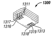
도 13a는 예시적 실시예에 따라 제 11 권선 구성 내의 쓰리 턴 클립 권선, 적어도 하나의 자기 파우더 시트, 및 수평으로 배향된 코어 영역을 갖는 소형 파워 인덕터의 상부 측의 분해도 및 사시도,
도 13b는 예시적 실시예에 따라 중간 제조 단계 동안 도 13a에 도시된 소형 파워 인덕터의 상부 측의 사시도,
도 13c는 예시적 실시예에 따라 도 13a에 도시된 소형 파워 인덕터의 하부 측의 사시도,
도 13d는 예시적 실시예에 따라 도 13a, 도 13b, 및 도 13c에 도시된 소형 파워 인덕터의 제 11 권선 구성의 사시도,
도 14a는 예시적 실시예에 따라 제 12 권선 구성 내의 원 턴 클립 권선, 압연된(rolled) 자기 파우더 시트, 및 수평으로 배향된 코어 영역을 갖는 소형 파워 인덕터의 상부 측의 분해도 및 사시도,
도 14b는 예시적 실시예에 따라 도 14a에 도시된 소형 파워 인덕터의 하부 측의 사시도, 및
도 14c는 예시적 실시예에 따라 도 14a 및 도 14b에 도시된 소형 파워 인덕터의 제 12 권선 구성의 사시도를 도시한다.FIG. 1A is an exploded view and perspective view of a top side of a small power inductor having a winding in a first winding configuration, at least one magnetic powder sheet, and a vertically oriented core region in accordance with an exemplary embodiment;
1B is an exploded view and perspective view of a lower side of the miniature power inductor shown in FIG. 1A according to an exemplary embodiment,
1C is a perspective view of a first winding configuration of the miniature power inductor shown in FIGS. 1A and 1B, according to an exemplary embodiment; FIG.
Figure 2a is an exploded view and perspective view of a top side of a small power inductor having a winding in a secondary winding configuration, at least one magnetic powder sheet, and a horizontally oriented core region in accordance with an exemplary embodiment;
Figure 2B is an exploded view and perspective view of the underside of the miniature power inductor shown in Figure 2a according to an exemplary embodiment,
FIG. 2C is a perspective view of a second winding configuration of the miniature power inductor shown in FIGS. 2A and 2B, according to an exemplary embodiment; FIG.
Figure 3a is a cross-sectional view of a portion of a winding in a second winding configuration, at least one magnetic powder sheet and a horizontally oriented core region having at least one terminal located on a printed wiring circuit board in accordance with an exemplary embodiment An exploded view and a perspective view of the upper side of the small power inductor,
FIG. 3B is an exploded view and perspective view of the underside of the miniature power inductor shown in FIG. 3A in accordance with an exemplary embodiment,
3C is a perspective view of a second winding configuration of the miniature power inductor shown in Figs. 3A and 3B, according to an exemplary embodiment; Fig.
4A is an exploded view and perspective view of a top side of a small power inductor having a plurality of windings in a third winding configuration, at least one magnetic powder sheet, and a horizontally oriented core region in accordance with an exemplary embodiment,
4B is an exploded view and perspective view of the underside of the miniature power inductor shown in FIG. 4A, in accordance with an exemplary embodiment;
4C is a perspective view of a third winding configuration of the miniature power inductor shown in Figs. 4A and 4B, according to an exemplary embodiment; Fig.
5A is an exploded view and perspective view of a top side of a miniature power inductor having a preformed coil and at least one magnetic powder sheet in accordance with an exemplary embodiment,
FIG. 5B illustrates a perspective view of the miniature power inductor shown in FIG. 5A according to an exemplary embodiment,
6A is an exploded view and perspective view of a top side of a small power inductor having a plurality of windings in a fourth winding configuration, at least one magnetic powder sheet, and a plurality of horizontally oriented core areas in accordance with an exemplary embodiment;
6B is an exploded view and perspective view of a lower side of the miniature power inductor shown in Fig. 6A, according to an exemplary embodiment; Fig.
6C is a perspective view of a fourth winding configuration of the miniature power inductor shown in Figs. 6A and 6B, according to an exemplary embodiment; Fig.
7A is an exploded view and perspective view of a top side of a small power inductor having a winding in a fifth winding configuration, at least one magnetic powder sheet, and a plurality of horizontally oriented core areas in accordance with an exemplary embodiment;
7B is an exploded view and a perspective view of the underside of the miniature power inductor shown in FIG. 7A, according to an exemplary embodiment;
7C is a perspective view of a fifth winding configuration of the miniature power inductor shown in Figs. 7A and 7B, according to an exemplary embodiment; Fig.
8A is an exploded view and perspective view of a top side of a small power inductor having a winding in a sixth winding configuration, at least one magnetic powder sheet, and a vertically oriented core region and a circularly oriented core region in accordance with an exemplary embodiment;
8B is an exploded view and perspective view of the underside of the miniature power inductor shown in FIG. 8A in accordance with an exemplary embodiment,
8C is a perspective view of a sixth winding configuration of the miniature power inductor shown in Figs. 8A and 8B, according to an exemplary embodiment; Fig.
9A is an exploded view and perspective view of a top side of a miniature power inductor having a one turn winding in a seventh winding configuration, at least one magnetic powder sheet, and a horizontally oriented core region in accordance with an exemplary embodiment;
FIG. 9B is a perspective view of the upper side of the miniature power inductor shown in FIG. 9A during the intermediate manufacturing steps, according to an exemplary embodiment; FIG.
9C is a bottom perspective view of the miniature power inductor shown in FIG. 9A, according to an exemplary embodiment,
9D is a perspective view of a seventh winding configuration of the miniature power inductor shown in Figs. 9A, 9B, and 9C, according to an exemplary embodiment; Fig.
10A is an exploded view and perspective view of a top side of a miniature power inductor having a two turn winding in a eighth winding configuration, at least one magnetic powder sheet, and a horizontally oriented core region in accordance with an exemplary embodiment;
10B is a perspective view of the upper side of the miniature power inductor shown in FIG. 10A during the intermediate manufacturing steps, according to an exemplary embodiment;
10C is a bottom perspective view of the miniature power inductor shown in FIG. 10A, according to an exemplary embodiment; FIG.
10D is a perspective view of an eighth winding configuration of the miniature power inductor shown in Figs. 10A, 10B, and 10C in accordance with an exemplary embodiment; Fig.
11A is an exploded view and perspective view of a top side of a miniature power inductor having a three turn winding in a ninth winding configuration, at least one magnetic powder sheet, and a horizontally oriented core region in accordance with an exemplary embodiment,
11B is a perspective view of the upper side of the miniature power inductor shown in FIG. ≪ RTI ID = 0.0 > 11A < / RTI &
11C is a perspective view of the lower side of the miniature power inductor shown in FIG. ≪ RTI ID = 0.0 > 11A < / RTI &
11D is a perspective view of a ninth winding configuration of the miniature power inductor shown in Figs. 11A, 11B, and 11C, according to an exemplary embodiment; Fig.
12A is an exploded view and perspective view of a top side of a miniature power inductor having a one-turn clip winding, at least one magnetic powder sheet, and a horizontally oriented core region in a tenth winding configuration in accordance with an exemplary embodiment;
12B is a perspective view of the upper side of the miniature power inductor shown in FIG. 12A during the intermediate manufacturing steps, according to an exemplary embodiment;
12C is a perspective view of the lower side of the miniature power inductor shown in FIG. 12A, in accordance with an exemplary embodiment,
12D is a perspective view of a tenth winding configuration of the miniature power inductor shown in Figs. 12A, 12B, and 12C in accordance with an exemplary embodiment; Fig.
13A is an exploded view and perspective view of a top side of a miniature power inductor having a three-turn clip winding, at least one magnetic powder sheet, and a horizontally oriented core region in a twelfth winding configuration in accordance with an exemplary embodiment;
13B is a perspective view of the upper side of the miniature power inductor shown in FIG. 13A during the intermediate manufacturing steps, according to an exemplary embodiment;
13C is a bottom perspective view of the miniature power inductor shown in FIG. 13A, according to an exemplary embodiment; FIG.
13D is a perspective view of the eleventh winding configuration of the miniature power inductor shown in Figs. 13A, 13B, and 13C, according to an exemplary embodiment; Fig.
14A is an exploded view and perspective view of a top side of a miniature power inductor having a one-turn clip winding, a rolled magnetic powder sheet, and a horizontally oriented core region in a twelfth winding configuration in accordance with an exemplary embodiment;
14B is a bottom perspective view of the miniature power inductor shown in FIG. 14A, according to an exemplary embodiment, and FIG.
14C shows a perspective view of a twelfth winding configuration of the miniature power inductor shown in Figs. 14A and 14B according to an exemplary embodiment.
도 1 ~ 14를 참조하면, 자기 소자 또는 장치의 여러 도시된, 예시적 실시예들의 몇몇 도면이 나타나 있다. 예시적 실시예에 있어서, 이하 설명되는 본 발명의 이익들이 다른 타입의 장치들에 이익을 미칠 수 있음을 인정함에도 불구하고, 본 발명의 장치는 인덕터이다. 이하 설명되는 재료들 및 기술들은 저 프로파일 인덕터의 제조에 특히 유리하다고 여겨진다고 하나, 인덕터는 본 발명의 이익들이 인식될 수 있는 전기 소자의 하나의 타입일 뿐이라고 인정된다. 따라서, 명세서는 단지 도시하는 목적을 위해 설명하는 것이고 본 발명의 이익들은 트랜스포머들에 국한되지는 않고 이를 포함하는 다른 전기 소자와 마찬가지로, 다른 크기 및 다른 타입의 인덕터에 이익을 미친다고 생각된다. 그로므로, 본 발명의 개념의 실행은 단지 도면들에 도시되고 여기에 설명된 예시적 실시예들에만 제한되는 것은 아니다. 추가적으로, 도면들은 스케일링(scale)된 것이 아니고 여러 소자들의 두께 및 다른 크기는 명확함을 목적으로 과장된 것으로 이해되야 한다. Referring to Figures 1-14, several views of various illustrated, exemplary embodiments of magnetic elements or devices are shown. In an exemplary embodiment, the apparatus of the present invention is an inductor, although it is appreciated that the benefits of the present invention described below may benefit other types of devices. While the materials and techniques described below are considered particularly advantageous for the manufacture of low profile inductors, it is recognized that the inductor is only one type of electrical device in which the benefits of the present invention can be appreciated. It is therefore contemplated that the description is merely for illustrative purposes and that the benefits of the present invention are not limited to transformers and benefit other sizes and types of inductors, as well as other electrical components comprising the same. As such, the practice of the inventive concept is not limited to the exemplary embodiments shown in the drawings and described herein. In addition, the drawings are not to scale, and the thickness and other dimensions of the various elements should be understood to be exaggerated for the sake of clarity.
도 1a ~ 1c를 참조하면, 자기 소자 또는 장치(100)의 제 1 실시예의 몇몇 도면들이 나타나있다. 도 1a는 예시적 실시예에 따라 제 1 권선 구성 내의 권선, 적어도 하나의 자기 파우더 시트 및 수직으로 배향된 코어 영역을 갖는 소형 파워 인덕터의 상부 측의 분해도 및 사시도를 도시한다. 도 1b는 예시적 실시예에 따라 도 1a에 도시된 소형 파워 인덕터의 하부 측의 분해도 및 사시도를 도시한다. 도 1c는 예시적 실시예에 따라 도 1a 및 도 1b에 도시된 소형 파워 인덕터의 제 1 권선 구성의 사시도를 도시한다.1A-1C, several views of a first embodiment of a magnetic element or
이러한 실시예에 따르면, 소형 파워 인덕터(100)는 적어도 하나의 자기 파우더 시트(110, 120, 130) 및 제 1 권선 구성(150) 내의 적어도 하나의 자기 파우더 시트(110, 120, 130)와 결합된 권선(140)을 갖추어 이루어진다. 이러한 실시예에 도시된 바와 같이, 소형 파워 인덕터(100)는 하부 표면(112) 및 상부 표면(114)을 갖는 제 1 자기 파우더 시트(110), 하부 표면(122) 및 상부 표면(124)을 갖는 제 2 자기 파우더 시트(120), 및 하부 표면(132) 및 상부 표면(134)을 갖는 제 3 자기 파우더 시트(130)를 갖추어 이루어진다. 예시적 실시예에 있어서, 각각의 자기 파우더 시트는 대한민국 인천의 창성 법인(Chang Sung Incorporated)에 의해 제조되고 생산품 번호 20u-eff 플렉시블 자기 시트(Flexible Magnetic Sheet)로 판매되는 자기 파우더 시트일 수 있다. 또한, 이러한 자기 파우더 시트들은 특정 방향으로 우세하게 배향되는 결정립(grain)을 갖는다. 따라서, 더 높은 인덕턴스는 자계가 우세한 결정립 배향의 방향에서 생성되는 때에 달성될 수 있다. 이러한 실시예가 세 개의 자기 파우더 시트들을 도시함에도 불구하고, 예시적 실시예의 정신 및 사상으로부터 벗어남 없이, 코어 영역을 증가 또는 감소시키기 위해, 권선 내의 턴(turns)의 수를 증가 또는 감소시키기 위해, 자기 시트들의 수는 증가 또는 감소될 수 있다. 또한, 이러한 실시예들이 자기 파우더 시트를 도시하고 있음에도 불구하고, 어떤 플렉시블한 시트가 예시적 실시예의 정신 및 사상으로부터 벗어남 없이, 적층되는데 사용될 수 있다.According to this embodiment, the
제 1 자기 파우더 시트(110)는 또한 제 1 자기 파우더 시트(110)의 하부 표면(112)의 대향하는 길이 방향의 에지들과 결합된 제 1 터미널(116) 및 제 2 터미널(118)을 포함한다. 이러한 터미널들(116, 118)은 예컨대, 인쇄 배선 회로 보드(미도시) 상에 있을 수 있는 전기 회로에 소형 파워 인덕터(100)를 결합시키는데 사용될 수 있다. 터미널들(116, 118) 각각은 또한 이하 더 설명되어질 하나 이상의 권선층들에 터미널들(116, 118)을 결합시키기 위해 비아(via: 117, 119)를 갖추어 이루어진다. 비아(117, 119)는 제 1 자기 파우더 시트(110)의 하부 표면(112) 상의 터미널들(116, 118)로부터 상부 표면(114)까지 진행되는 도전 커넥터(connectors)이다. 비아는 자기 파우더 시트들을 통해 홀을 드릴링(drilling)하고, 드릴링된(drilled) 홀(hole)의 내측 원주를 도전 재료로 도금함으로써 형성될 수 있다. 선택적으로, 도전 핀(pin)은 비아들 내의 도전 연결들을 확립하기 위해 드릴링된 홀들에 위치될 수 있다. 비아(117, 119)가 형상 내에서 원통형으로 도시됨에도 불구하고, 예시적 실시예의 정신 및 사상으로부터 벗어남 없이, 비아는 예컨대, 직사각형과 같은 다른 기하학적 형상일 수 있다. 일 예시적 실시예에 있어서, 전체 인덕터는 비아를 드릴링하기 전에 형성되고 압착될 수 있다. 터미널들이 대향하는 길이 방향의 에지들에 결합되어진 것처럼 보임에도 불구하고, 터미널들은 예시적 실시예의 정신 및 사상으로부터 벗어남 없이, 제 1 자기 파우더 시트의 하부 표면 상의 다른 위치에 결합될 수 있다. 또한, 각 터미널이 하나의 비아를 갖도록 도시되었음에도 불구하고, 예시적 실시예의 정신 및 사상으로부터 벗어남 없이, 어플리케이션에 의존하여, 직렬보다는 병렬로 하나 이상의 권선 층들을 위치시키기 위해, 추가적인 비아들이 터미널들 각각 내에 형성될 수 있다.The first
제 2 자기 파우더 시트(120)는 제 2 자기 파우더 시트(120)의 하부 표면(122)에 결합된 제 1 권선층(126) 및 제 2 자기 파우더 시트(120)의 상부 표면(124)에 결합된 제 2 권선층(128)을 갖는다. 권선층(126, 128) 둘 모두는 권선(140)을 형성하기 위해 조합된다. 제 1 권선층(126)은 비아(117)를 통해 터미널(116)에 결합된다. 제 2 권선층(128)은 제 2 자기 파우더 시트(120) 내에 형성된 비아(127)를 통해 제 1 권선층(126)에 결합된다. 비아(127)는 제 2 자기 파우더 시트(120)의 하부 표면(122)으로부터 상부 표면(124)까지 뻗어 있다. 제 2 권선층(128)은 비아(129, 119)를 통해 제 2 터미널(118)에 결합된다. 비아(129)는 제 2 자기 파우더 시트(120)의 상부 표면(124)으로부터 하부 표면(122)까지 뻗어 있다. 두 개의 권선층들이 이 실시예에서 제 2 자기 파우더 시트에 결합된 것으로 도시되었음에도 불구하고, 예시적 실시예의 정신 및 사상으로부터 벗어남 없이 제 2 자기 파우더 시트에 결합된 하나의 권선층이 있을 수 있다.The second
권선층들(126, 128)은 제 2 자기 파우더 시트(120)에 결합된 도전 구리층으로부터 형성된다. 이 도전 구리층은 예시적 실시예의 정신 및 사상으로부터 벗어남 없이 스탬핑된 구리 호일, 에칭된 구리 트레이스, 또는 미리 형성된 코일을 포함할 수 있으나 이에 국한되지는 않는다. 에칭된 구리 트레이스는 화학적 프로세스, 포토리소그래피(photolithography) 기술들, 또는 레이저 에칭 기술들에 의해 형성될 수 있으나, 이에 국한되지는 않는다. 이러한 실시예에 도시된 바와 같이, 권선층은 직사각형-형상 나선 패턴이다. 그러나 다른 패턴들도 예시적 실시예의 정신 및 사상으로부터 벗어남 없이 권선을 형성하는데 사용될 수 있다. 구리가 도전 재료로서 사용됨에도 불구하고, 다른 도전 재료들도 예시적 실시예의 정신 및 사상으로부터 벗어남 없이 사용될 수 있다. 터미널들(116, 118)은 또한 스탬핑된 구리 호일, 에칭된 구리 트레이스를 이용하여, 또는 다른 적합한 방법에 의해 형성될 수 있다.The winding
이러한 실시예에 따라, 제 2 권선층(128)이 절연될 수 있도록 및 또한 더 높은 전류 흐름을 취급하기 위해 코어 영역이 증가될 수 있도록, 제 3 자기 파우더 시트(130)는 제 2 자기 파우더 시트(120)의 상부 표면(124) 상에 위치된다. According to this embodiment, the third
제 3 자기 파우더 시트가 권선층을 갖도록 도시되지 않았음에도 불구하고, 권선층은 예시적 실시예의 정신 및 사상으로부터 벗어남 없이 제 2 자기 파우더 시트의 상부 표면 상의 권선층 대신 제 3 자기 층의 하부 표면에 부가될 수 있다. 추가적으로, 제 3 자기 파우더 시트가 권선층을 갖도록 도시되지 않았음에도 불구하고, 권선층은 예시적 실시예의 정신 및 사상으로부터 벗어남 없이 제 3 자기층의 상부 표면에 부가될 수 있다.Although the third magnetic powder sheet is not shown to have a winding layer, the winding layer may be formed on the lower surface of the third magnetic layer instead of the winding layer on the upper surface of the second magnetic powder sheet without deviating from the spirit and spirit of the exemplary embodiment Can be added. Additionally, although the third magnetic powder sheet is not shown to have a winding layer, the winding layer may be added to the upper surface of the third magnetic layer without departing from the spirit and spirit of the exemplary embodiment.
권선층들(126, 128) 및/또는 터미널들(116, 118)을 갖는 자기 파우더 시트들(110, 120, 130) 각각을 형성하는 동안, 시트들(110, 120, 130)은 예컨대, 수압과 같은 높은 압력으로 압착되고, 소형 파워 인덕터(100)를 형성하기 위해 서로 적층된다. 시트들(110, 120, 130)이 서로 압착된 후에, 비아들이 상기한 바와 같이, 형성된다. 이러한 실시예에 따라, 전형적인 인덕터에서 일반적으로 나타나는 권선과 코어 사이의 물리적 갭이 제거된다. 물리적 갭의 제거는 권선의 진동으로부터의 청각적 노이즈(noise)를 최소화하는 경향이 있다.During formation of each of the
소형 파워 인덕터(100)는 큐브(cube) 형상으로 도시된다. 그러나, 직사각형, 원형, 또는 타원형 형상을 포함하나 이에 국한되지는 않는 다른 기하학적 형상들이 예시적 실시예의 정신 및 사상으로부터 벗어남 없이 사용될 수 있다.The
권선(140)은 제 1 권선층(126) 및 제 2 권선층(128)을 포함하고 수직으로 배향된 코어(157)를 갖는 제 1 권선 구성(150)을 형성한다. 제 1 권선 구성(150)은 제 1 터미널(116)에서 시작하고, 그 후에 제 1 권선층(126)까지 진행되며, 그 후에 제 2 권선층(128)까지 진행되고, 그 뒤에 제 2 터미널(118)까지 진행된다. 따라서, 이러한 실시예에 있어서, 자계는 결정립 배향의 방향에 수직인 방향에서 생성될 수 있고 이에 따라 낮은 인덕턴스를 달성할 수 있으며, 또는 자계는 결정립 배향의 방향에 평행한 방향에서 생성될 수 있고 이에 따라 자기 파우더 시트가 돌출된 방향에 의존하여 높은 인덕턴스를 달성할 수 있다.The winding 140 forms a first winding
도 2a ~ 2c를 참조하면, 자기 소자 또는 장치(200)의 제 2 실시예의 몇몇 도면들이 나타나있다. 도 2a는 예시적 실시예에 따라 제 2 권선 구성 내의 권선, 적어도 하나의 자기 파우더 시트 및 수평으로 배향된 코어 영역을 갖는 소형 파워 인덕터의 상부 측의 분해도 및 사시도를 도시한다. 도 2b는 예시적 실시예에 따라 도 2a에 도시된 소형 파워 인덕터의 하부 측의 분해도 및 사시도를 도시한다. 도 2c는 예시적 실시예에 따라 도 2a 및 도 2b에 도시된 소형 파워 인덕터의 제 2 권선 구성의 사시도를 도시한다.Referring to Figures 2A-2C, several views of a second embodiment of a magnetic element or
이러한 실시예에 따라, 소형 파워 인덕터(200)는 적어도 하나의 자기 파우더 시트(210, 220, 230, 240) 및 제 2 권선 구성(255) 내의 적어도 하나의 자기 파우더 시트(210, 220, 230, 240)에 결합된 권선(250)을 갖추어 이루어진다. 이러한 실시예에 도시된 바와 같이, 소형 파워 인덕터(200)는 하부 표면(212)과 상부 표면(214)을 갖는 제 1 자기 파우더 시트(210), 하부 표면(222)과 상부 표면(224)을 갖는 제 2 자기 파우더 시트(220), 하부 표면(232)과 상부 표면(234)을 갖는 제 3 자기 파우더 시트(230), 및 하부 표면(242)과 상부 표면(244)을 갖는 제 4 자기 파우더 시트(240)를 갖추어 이루어진다. 상기한 바와 같이, 예시적 자기 파우더 시트들은 대한민국 인천의 창성 법인에서 제조되고 생산품 번호 20u-eff 플렉시블 자기 시트로 판매되는 자기 파우더 시트들일 수 있고, 이는 상기한 것과 동일한 특성을 갖는다. 이 실시예가 네 개의 자기 파우더 시트들을 도시하고 있음에도 불구하고, 자기 시트들의 수는 예시적 실시예의 정신 및 사상으로부터 벗어남 없이 코어 영역을 증가 또는 감소시키기 위해 증가 또는 감소될 수 있다. 또한, 이 실시예가 자기 파우더 시트를 도시하고 있음에도 불구하고, 어떤 플렉시블한 시트가 예시적 실시예의 정신 및 사상으로부터 벗어남 없이, 적층되는데 사용될 수 있다.According to this embodiment, the
제 1 자기 파우더 시트(210)는 또한 제 1 자기 파우더 시트(210) 및 제 1 자기 파우더 시트(210)의 하부 표면(212)의 대향하는 길이 방향의 측면들과 결합된 제 1 터미널(216) 및 제 2 터미널(218)을 포함한다. 이러한 터미널들(216, 218)은 예컨대, 인쇄 배선 회로 보드(미도시) 상에 있을 수 있는 전기 회로에 소형 파워 인덕터(200)를 결합시키는데 사용될 수 있다. 제 1 자기 파우더 시트(210)는 또한 서로 비-접촉 관계로 터미널들(216, 218) 사이에 위치되고 터미널들(216, 218)과 실질적으로 동일한 방향에 모두 위치되는 제 1 하부 권선층 부분(260), 제 2 하부 권선층 부분(261), 제 3 하부 권선층 부분(262), 제 4 하부 권선층 부분(263), 및 제 5 하부 권선층 부분(264)을 포함한다. 이러한 하부 권선층 부분들(260, 261, 262, 263, 264)은 또한 제 1 자기 파우더 시트(210)의 하부 표면(212) 상에 위치된다.The first
터미널들(216, 218)의 각각은 하나 이상의 권선층들에 터미널들(216, 218)을 결합시키기 위해, 비아(280, 295)를 각각 갖추어 이루어진다. 추가적으로, 하부 권선층 부분들(260, 261, 262, 263, 264) 각각은 하부 권선층 부분들(260, 261, 262, 263, 264)을 이하 상세히 설명되는 각각의 상부 권선층 부분들(270, 271, 272, 273, 274, 275)에 결합시기기 위해 두 개의 비아들을 갖추어 이루어진다. 목록에 있는 것처럼, 하부 권선층 부분보다 상부 권선층 부분이 하나 더 많다.Each of the
제 2 자기 파우더 시트(220) 및 제 3 자기 파우더 시트(230)는 터미널들(216, 218), 하부 권선층 부분들(260, 261, 262, 263, 264), 및 상부 권선층 부분들(270, 271, 272, 273, 274, 275)을 서로 결합시키기 위한 복수의 비아들(280, 281, 282, 283, 284, 285, 290, 291, 292, 293, 294, 295)을 갖추어 이루어진다. The second
제 4 자기 파우더 시트(240)는 또한 제 1 자기 파우더 시트(210)의 하부 권선층 부분들(260, 261, 262, 263, 264)과 실질적으로 동일한 방향에 위치되는 제 1 상부 권선층 부분(270), 제 2 상부 권선층 부분(271), 제 3 상부 권선층 부분(272), 제 4 상부 권선층 부분(273), 제 5 상부 권선층 부분(274), 제 6 상부 권선층 부분(275)을 포함한다. 이러한 상부 권선층 부분들(270, 271, 272, 273, 274, 275)은 서로 비-접촉 관계로 위치된다. 이러한 상부 권선층 부분들(270, 271, 272, 273, 274, 275)은 또한 제 4 자기 파우더 시트(240)의 상부 표면(244) 상에 위치되고, 상부 권선층 부분들(270, 271, 272, 273, 274, 275)이 하부 권선층 부분들(260, 261, 262, 263, 264)과 실질적으로 동일한 방향에 위치됨에도 불구하고, 그것들이 서로 적절하게 연결될 수 있도록 그들 방향들 사이에는 작은 각이 형성된다. The fourth
상부 권선층 부분들(270, 271, 272, 273, 274, 275) 각각은 이하 상세히 설명되는 각각의 터미널(216, 218) 및 각각의 하부 권선층 부분들(260, 261, 262, 263, 264)에 상부 권성층 부분들(270, 271, 272, 273, 274, 275)을 결합시키기 위해 두 개의 비아들을 갖추어 이루어진다.Each of the upper winding
상부 권선층 부분들(270, 271, 272, 273, 274, 275), 하부 권선층 부분들(260, 261, 262, 263, 264), 및 터미널들(216, 218)은 스탬핑된 구리 호일, 에칭된 구리 트레이스, 또는 미리 형성된 코일을 포함하나 이에 국한되지 않는 상기한 방법들 중 어느 것에 의해 형성될 수 있다.The upper winding
제 1 자기 파우더 시트(210) 및 제 4 자기 파우더 시트(240)를 형성하는 동안, 제 2 자기 시트(220) 및 제 3 자기 시트(230)가 제 1 자기 파우더 시트(210)와 제 4 자기 파우더 시트(240) 사이에 위치된다. 자기 파우더 시트들(210, 220, 230, 240)은 예컨대, 수압과 같은 높은 압력에 의해 서로 압착되고, 소형 파워 인덕터(200)를 형성하기 위해 서로 적층된다. 시트들(210, 220, 230, 240)이 서로 압착된 후에, 비아들(280, 281, 282, 283, 284, 285, 290, 291, 292, 293, 294, 295)이 도 1a ~ 1c에 대해 제공된 설명에 따라 형성된다. 추가적으로, 코팅 또는 에폭시(미도시)가 제 4 자기 파우더 시트(240)의 상부 표면(244)에 절연층으로써 적용될 수 있다. 이 실시예에 따라, 전형적인 인덕터들에서 일반적으로 나타나는 권선 및 코어 사이의 물리적 갭이 제거된다. 물리적 갭의 제거는 권선의 진동으로부터의 청각적 노이즈를 최소화시키는 경향이 있다.The second
권선(250)은 수평으로 배향된 코어(257)를 갖는 제 2 권선 구성(255)을 형성한다. 제 2 권선 구성(255)은 제 1 터미널(216)에서 시작하고, 그 후에 비아(280)를 통해 제 1 상부 권선층 부분(270)으로 진행되며, 그 후에 비아(290)를 통해 제 1 하부 권선층 부분(260)으로 진행되고, 그 후에 비아(281)를 통해 제 2 상부 권선층 부분(271)으로 진행되며, 그 후에 비아(291)를 통해 제 2 하부 권선층 부분(261)으로 진행되고, 그 후에 비아(282)를 통해 제 3 상부 권선층 부분(272)으로 진행되며, 그 후에 비아(292)를 통해 제 3 하부 권선층 부분(262)으로 진행되고, 그 후에 비아(283)를 통해 제 4 상부 권선층 부분(273)으로 진행되며, 그 후에 비아(293)를 통해 제 4 하부 권선층 부분(263)으로 진행되고, 그 후에 비아(284)를 통해 제 5 상부 권선층 부분(274)으로 진행되며, 그 후에 비아(295)를 통해 제 5 하부 권선층 부분(264)으로 진행되고, 그 후에 비아(285)를 통해 제 6 상부 권선층 부분(275)으로 진행되며, 그 후에 비아(295)를 통해 제 2 터미널(218)로 진행된다. 이러한 실시예에 있어서, 자계는 결정립 배향의 방향과 수직한 방향에서 생성될 수 있고 이에 따라 낮은 인덕턴스를 달성할 수 있으며 또는 자계는 결정립 배향의 방향과 평행한 방향에서 생성될 수 있고 이에 따라 자기 파우더 시트가 돌출된 방향에 의존하여 높은 인덕턴스를 달성할 수 있다.Winding 250 forms a second winding
소형 파워 인덕터(200)는 정사각형 형상으로 도시된다. 그러나, 직사각형, 원형, 또는 타원형 형상을 포함하는, 그러나 이에 국한되지는 않는, 다른 기하학적 형상들이 예시적 실시예의 정신 및 사상으로부터 벗어남 없이 사용될 수 있다. 또한, 이러한 실시예가 여섯 개의 상부 권선층 부분들 및 다섯 개의 하부 권선층 부분들을 도시하고 있음에도 불구하고, 예시적 실시예의 정신 및 사상으로부터 벗어남 없이, 하부 권선층 부분보다 하나 이상 많은 상부 권선층 부분이 존재하기만 한다면, 상부 및 하부 권선층 부분들의 수는 어플리케이션의 요구사항에 의존하여 증가 또는 감소할 수 있다.The
도 3a ~ 3c를 참조하면, 자기 소자 또는 장치(300)의 제 3 실시예의 몇몇 도면들이 나타나있다. 도 3a는 예시적 실시예에 따라 인쇄 배선 회로 보드 상에 위치된 적어도 하나의 터미널 및 제 2 권선 구성 내의 권선의 한 부분, 적어도 하나의 자기 파우더 시트 및 수평으로 배향된 코어 영역을 갖는 소형 파워 인덕터의 상부 측의 분해도 및 사시도를 도시한다. 도 3b는 예시적 실시예에 따라 도 3a에 도시된 소형 파워 인덕터의 하부 측의 분해도 및 사시도를 도시한다. 도 3c는 예시적 실시예에 따라 도 3a 및 도 3b에 도시된 소형 파워 인덕터의 제 2 권선 구성의 사시도를 도시한다.Referring to Figures 3A-3C, several views of a third embodiment of a magnetic element or
도 3a ~ 3c에 도시된 소형 파워 인덕터(300)는 제 1 터미널(316), 제 2 터미널(318), 및 복수의 하부 권선층 부분들(360, 361, 362, 363, 364)이, 제 1 자기 파우더 시트(310)의 하부 표면(312) 위 대신에 기판(302)의 상부 표면(304) 위에 위치된다는 점을 제외하면 도 2a ~ 2c에 도시된 소형 파워 인덕터(200)와 유사하다. 도 2a ~ 2c에 도시된 소형 파워 인덕터와 유사한 두께 및 수행을 유지하기 위해, 제 1 자기 파우더 시트(310)가 소형 파워 인덕터(300)의 제조에 있어 사용되고, 복수의 비아들을 갖추어 이루어지며, 제 2 자기 파우더 시트(320) 및 제 3 자기 파우더 시트(330)도 이와 유사하다. 따라서, 네 개의 자기 파우더 시트들(310, 320, 330, 340)이 서로 적층되면, 소형 파워 인덕터(300)는 그것이 적절한 터미널들(316, 318) 및 복수의 하부 권선층 부분들(360, 361, 362, 363, 364)을 갖는 기판(302)에 결합될 때까지 완전히 펼쳐지진 않는다. 압착된 자기 파우더 시트들(310, 320, 330, 340)은 기판(302)으로의 비아들 각각을 납땜하는 것을 포함하여, 다만 이에 국한되지는 않는, 어느 알려진 방식으로 기판(302)에 결합될 수 있다. 이러한 실시예에 따르면, 기판(302)은 인쇄 배선 회로 보드 및/또는 터미널들 및 그 위에 복수의 하부 권선층 부분들을 가질 수 있는 다른 기판들을 포함할 수 있으나 이에 국한되진 않는다. 소형 파워 인덕터(300)의 제조는, 도 2a ~ 2c와 관련하여 설명되고 도시된 바와 같이, 소형 파워 인덕터(200)의 유연성의 전부가 아니라도 대부분을 구비할 것이다. The
도 4a ~ 4c를 참조하면, 자기 소자 또는 장치(400)의 제 4 실시예의 몇몇 도면들이 나타나있다. 도 4a는 예시적 실시예에 따라 제 3 권선 구성 내의 복수의 권선들, 적어도 하나의 자기 파우더 시트 및 수평으로 배향된 코어 영역을 갖는 소형 파워 인덕터의 상부 측의 분해도 및 사시도를 도시한다. 도 4b는 예시적 실시예에 따라 도 4a에 도시된 소형 파워 인덕터의 하부 측의 분해도 및 사시도를 도시하고, 도 4c는 예시적 실시예에 따라 도 4a 및 도 4b에 도시된 소형 파워 인덕터의 제 3 권선 구성의 사시도를 도시한다. 4A-4C, several views of a fourth embodiment of a magnetic element or
이러한 실시예에 따르면, 소형 파워 인덕터(400)는 적어도 하나의 자기 파우더 시트(410, 420, 430, 440) 및 제 3 권선 구성(455) 내의 적어도 하나의 자기 파우더 시트(410, 420, 430, 440)에 결합된 복수의 권선들(450, 451, 452)을 갖추어 이루어진다. 이러한 실시예에 도시된 바와 같이, 소형 파워 인덕터(400)는 하부 표면(412) 및 상부 표면(414)을 갖는 제 1 자기 파우더 시트(410), 하부 표면(422) 및 상부 표면(424)을 갖는 제 2 자기 파우더 시트(420), 하부 표면(432) 및 상부 표면(434)을 갖는 제 3 자기 파우더 시트(430), 및 하부 표면(442) 및 상부 표면(444)을 갖는 제 4 자기 파우더 시트(440)를 갖추어 이루어진다. 상기한 바와 같이, 예시적 자기 파우더 시트들은 대한민국 인천의 창성 법인에 의해 제조되고 생산품 번호 20u-eff 플렉시블 자기 시트로 판매되는 자기 파우더 시트들일 수 있고, 이는 상기한 바와 동일한 특성을 갖는다. 이러한 실시예가 네 개의 자기 파우더 시트들을 도시하고 있음에도 불구하고, 자기 시트들의 수는 예시적 실시예의 정신 및 사상으로부터 벗어남 없이 코어 영역을 증가 또는 감소시키기 위해 증가 또는 감소될 수 있다. 또한, 이러한 실시예가 자기 파우더 시트를 도시하고 있음에도 불구하고, 어떤 플렉시블한 시트가 예시적 실시예의 정신 및 사상으로부터 벗어남 없이, 적층되는데 사용될 수 있다.According to this embodiment, the
제 1 자기 파우더 시트(410)는 또한 제 1 터미널(411), 제 2 터미널(413), 제 3 터미널(415), 제 4 터미널(416), 제 5 터미널(417), 및 제 6 터미널(418)을 포함한다. 각 권선(450, 451, 452)에 대해 두 개의 터미널들이 존재한다. 제 1 터미널(411) 및 제 2 터미널(413)은 제 1 자기 파우더 시트(410)의 하부 표면(412)의 대향하는 측면들에 결합된다. 제 3 터미널(415) 및 제 4 터미널(416)은 제 1 자기 파우더 시트(410)의 하부 표면(412)의 대향하는 측면들에 결합된다. 제 5 터미널(417) 및 제 6 터미널(418)은 제 1 자기 파우더 시트(410)의 하부 표면(412)의 대향하는 측면들에 결합된다. 추가적으로, 제 1 터미널(411), 제 3 터미널(415), 및 제 5 터미널(417)은 서로 인접하고 제 1 자기 파우더 시트(410)의 하부 표면(412)의 하나의 에지를 따라 위치되고, 반면에 제 2 터미널(413), 제 4 터미널(415), 및 제 6 터미널(418)은 서로 인접하고 제 1 자기 파우더 시트(410)의 하부 표면(412)의 대향하는 에지를 따라 위치된다. 이러한 터미널들(411, 413, 415, 416, 417, 418)은 예컨대, 인쇄 배선 회로 보드(미도시) 상에 있을 수 있는, 전기 회로에 소형 파워 인덕터(400)를 결합시키는데 사용될 수 있다. The first
제 1 자기 파우더 시트(410)는 또한 제 1 자기 파우더 시트(410)의 하부 표면(412) 상에 및 터미널들(411, 413, 415, 416, 417, 418)과 실질적으로 동일한 방향에 모두 위치하는 제 1 하부 권선층 부분(460), 제 2 하부 권선층 부분(461), 및 제 3 하부 권선층 부분(462)을 포함한다. 제 1 하부 권선층 부분(460)은 제 1 터미널(411)과 제 2 터미널(413) 사이에 위치되고 서로 비-접촉 관계로 위치된다. 제 1 하부 권선층 부분(460), 제 1 터미널(411), 및 제 2 터미널(413)은 제 1 권선(450)의 부분을 형성하기 위해 조합된다. 추가적으로, 제 2 하부 권선층 부분(461)은 제 3 터미널(415)과 제 4 터미널(416) 사이에 위치되고 서로 비-접촉 관계로 위치된다. 제 2 하부 권선층 부분(461), 제 3 터미널(415), 및 제 4 터미널(416)은 제 2 권선(451)의 부분을 형성하기 위해 조합된다. 더욱이, 제 3 하부 권선층 부분(462)은 제 5 터미널(417)과 제 6 터미널(418) 사이에 위치되고 서로 비-접촉 관계로 위치된다. 제 3 하부 권선층 부분(462), 제 5 터미널(417), 및 제 6 터미널(418)은 제 3 권선(452)의 부분을 형성하기 위해 조합된다.The first
터미널들(411, 413, 415, 416, 417, 418) 각각은 터미널들(411, 413, 415, 416, 417, 418)을 하나 이상의 권선층들에 결합시키기 위해 비아(480, 482, 484, 491, 493, 495)를 각각 갖추어 이루어진다. 추가적으로, 하부 권선층 부분들(460, 461, 462) 각각은 이하 상세히 설명되는 각각의 상부 권선층 부분들(470, 471, 472, 473, 474, 475)에 하부 권선층 부분들(460, 461, 462)을 결합시키기 위해 두 개의 비아들을 갖추어 이루어진다. 목록에 있고 상기한 바와 같이, 권선 하나당, 하부 권선층 부분보다 상부 권선층 부분이 하나씩 더 많이 존재한다.Each of the
제 2 자기 파우더 시트(420) 및 제 3 자기 파우더 시트(430)는 터미널들(411, 413, 415, 416, 417, 418), 하부 권선층 부분들(460, 461, 462), 및 상부 권선층 부분들(470, 471, 472, 473, 474, 475)을 서로 결합시키 위해 복수의 비아들(480, 481, 482, 483, 484, 485, 490, 491, 492, 493, 494, 495)을 갖추어 이루어진다.The second
제 4 자기 파우더 시트(440)는 또한 제 1 자기 파우더 시트(410)의 하부 권선층 부분들(460, 461, 462)과 실질적으로 동일한 방향에 위치되는 제 1 상부 권선층 부분(470), 제 2 상부 권선층 부분(471), 제 3 상부 권선층 부분(472), 제 4 상부 권선층 부분(473), 제 5 상부 권선층 부분(474), 제 6 상부 권선층 부분(475)을 포함한다. 이러한 상부 권선층 부분들(470, 471, 472, 473, 474, 475)은 서로 비-접촉 관계로 위치된다. 이러한 상부 권선층 부분들(470, 471, 472, 473, 474, 475)은 또한 제 4 자기 파우더 시트(440)의 상부 표면(444) 상에 위치된다. 상부 권선층 부분들(470, 471, 472, 473, 474, 475)이 하부 권선층 부분들(460, 461, 462)과 실질적으로 동일한 방향에 위치됨에도 불구하고, 그것들이 서로 적절하게 연결될 수 있도록 그것들의 방향들 사이에는 작은 각이 형성된다. The fourth
상부 권선층 부분들(470, 471, 472, 473, 474, 475) 각각은 이하 상세히 설명되는 각각의 터미널(411, 413, 415, 416, 417, 418) 및 각각의 하부 권선층 부분들(460, 461, 462)에 상부 권선층 부분들(470, 471, 472, 473, 474, 475)을 결합시키기 위해 두 개의 비아들을 갖추어 이루어진다. Each of the upper winding
상부 권선층 부분들(470, 471, 472, 473, 474, 475), 하부 권선층 부분들(460, 461, 462), 및 터미널들(411, 413, 415, 416, 417, 418)은 스탬핑된 구리 호일, 에칭된 구리 트레이스, 또는 밀 형성된 코일을 포함하나 이에 국한되지 않는 상기한 방법들 중 어느 것에 의해 형성될 수 있다.The upper winding
제 1 자기 파우더 시트(410)와 제 4 자기 파우더 시트(440)를 형성하는 동안, 제 2 자기 시트(420)와 제 3 자기 시트(430)는 제 1 자기 파우더 시트(410)와 제 4 자기 파우더 시트(440) 사이에 위치된다. 자기 파우더 시트들(410, 420, 430, 440)은 예컨대 수압과 같은 높은 압력으로 서로 압착되고, 소형 파워 인덕터(400)를 형성하기 위해 서로 적층된다. 시트들(410, 420, 430, 440)이 서로 압착된 후에, 비아들(480, 481, 482, 483, 484, 485, 490, 491, 492, 493, 494, 495)은 도 1a ~ 1c에 대해 제공된 설명에 따라 형성된다. 추가적으로, 코팅 또는 에폭시(미도시)가 제 4 자기 파우더 시트(440)의 상부 표면(444)에 절연층으로서 적용될 수 있다. 이러한 실시예에 따르면, 전형적인 인덕터들에서 일반적으로 나타나는 권선과 코어 사이의 물리적 갭이 제거된다. 이러한 물리적 갭의 제거는 권선의 진동으로부터의 청각적 노이즈를 최소화하는 경향이 있다.The second
권선들(450, 451, 452)은 수평으로 배향된 코어(457)를 갖는 제 3 권선 구성(455)을 형성한다. 제 1 권선(450)은 제 1 터미널(411)에서 시작되고, 그 후에 비아(480)를 통해 제 1 상부 권선층 부분(470)으로 진행되며, 그 후에 비아(490)를 통해 제 1 하부 권선층 부분(460)으로 진행되고, 그 후에 비아(481)를 통해 제 2 상부 권선층 부분(471)으로 진행되며, 그 후에 비아(491)를 통해 제 2 터미널(413)로 진행되고, 그리고는 제 1 권선(450)을 완성한다. 제 2 권선(451)은 제 3 터미널(415)에서 시작되고, 그 후에 비아(482)를 통해 제 3 상부 권선층 부분(472)으로 진행되며, 그 후에 비아(492)를 통해 제 2 하부 권선층 부분(461)으로 진행되고, 그 후에 비아(483)를 통해 제 4 상부 권선층 부분(473)으로 진행되며, 그 후에 비아(493)를 통해 제 4 터미널(416)로 진행되고, 그리고는 제 2 권선(451)을 완성한다. 제 3 권선(452)은 제 5 터미널(417)에서 시작되고, 그 후에 비아(484)를 통해 제 5 상부 권선층 부분(474)으로 진행되며, 그 후에 비아(494)를 통해 제 3 하부 권선층 부분(462)으로 진행되고, 그 후에 비아(485)를 통해 제 6 상부 권선층 부분(475)으로 진행되며, 그 후에 비아(495)를 통해 제 6 터미널(418)로 진행되고, 그리고는 제 3 권선(452)을 완성한다.
세 개의 권선들이 이러한 실시예에서 도시됨에도 불구하고, 더 많은 또는 더 적은 권선들이 예시적 실시예의 정신 및 사상으로부터 벗어남 없이 형성될 수 있다. 추가적으로, 세 개의 권선들은 요구되는 어플리케이션 및 요구사항들에 의존하여 직렬 배열 또는 병렬 배열의 인쇄 배선 회로 보드 또는 기판(미도시) 상에 설치될 수 있다. 이러한 유연성은 이 소형 파워 인덕터(400)가 트랜스포머 또는 인덕터로서 사용되어지도록 허용한다.Although three windings are shown in this embodiment, more or fewer windings can be formed without departing from the spirit and spirit of the exemplary embodiment. In addition, the three windings may be mounted on a printed wiring circuit board or substrate (not shown) in a serial or parallel arrangement, depending on the required applications and requirements. This flexibility allows this
이러한 실시예에 있어서, 자계는 결정립 배향의 방향과 수직인 방향에서 생성될 수 있고, 이에 따라 낮은 인덕턴스를 달성하며, 또는 자계가 결정립 배향의 방향과 평행인 방향에서 생성될 수 있고, 이에 따라 자기 파우더 시트가 돌출된 방향에 의존하여 높은 인덕턴스를 달성한다. In this embodiment, the magnetic field can be generated in a direction perpendicular to the direction of grain orientation, thereby achieving a low inductance, or a magnetic field can be generated in a direction parallel to the direction of the grain orientation, A high inductance is achieved depending on the direction in which the powder sheet protrudes.
소형 파워 인덕터(400)는 정사각형 형태로서 도시된다. 그러나, 직사각형, 원형, 또는 타원형 형상들을 포함하나 이에 국한되지는 않는 다른 기하학적 형상들이 예시적 실시예의 정신 및 사상으로부터 벗어남 없이 이용될 수 있다. 또한, 이러한 실시예가 각각의 권선에 대해 하나의 하부 권선층 부분 및 두 개의 상부 권선층 부분들을 도시하고 있음에도 불구하고, 상부 및 하부 권선층 부분들의 수는, 예시적 실시예의 정신 및 사상으로부터 벗어남 없이, 각각의 권선에 대해 하부 권선층 부분보다 상부 권선층 부분의 수가 하나 이상 더 많은 한, 어플리케이션의 요구사항들에 의존하여 증가할 수 있다.The
도 5a ~ 5b를 참조하면, 자기 소자 또는 장치(500)의 제 5 실시예의 몇몇 도면들이 나타나있다. 도 5a는 예시적 실시예에 따라 미리 형성된 코일 및 적어도 하나의 자기 파우더 시트를 갖는 소형 파워 인덕터의 상부측의 분해도 및 사시도를 도시한다. 도 5b는 예시적 실시예에 따라 도 5a에 도시된 소형 파워 인덕터의 사시 투명도를 도시한다.5A-5B, several views of a fifth embodiment of a magnetic element or
이러한 실시예에 있어서, 소형 파워 인덕터(500)는 적어도 하나의 자기 파우더 시트(510, 520, 530, 540) 및 적어도 하나의 자기 파우더 시트(510, 520, 530, 540)에 결합된 적어도 하나의 미리 형성된 코일(550)을 갖추어 이루어진다. 이 실시예에 도시된 바와 같이, 소형 파워 인덕터(500)는 하부 표면(512)과 상부 표면(514)을 갖는 제 1 자기 파우더 시트(510), 하부 표면(522)과 상부 표면(524)을 갖는 제 2 자기 파우더 시트(520), 하부 표면(532)과 상부 표면(534)을 갖는 제 3 자기 파우더 시트(530), 및 하부 표면(542)과 상부 표면(544)을 갖는 제 4 자기 파우더 시트(540)를 갖추어 이루어진다. 상기한 바와 같이, 예시적 자기 파우더 시트들은 대한민국 인천의 창성 법인에 의해 제조되고 생산품 번호 20u-eff 플렉시블 자기 시트로 판매되는 자기 파우더 시트들일 수 있고, 이는 상기한 바와 동일한 특성들을 갖는다. 이 실시예가 네 개의 자기 파우더 시트들을 도시하고 있음에도 불구하고, 자기 파우더 시트들의 수는 예시적 실시예의 정신 및 사상으로부터 벗어남 없이 코어 영역을 증가 또는 감소시키기 위해 증가 또는 감소될 수 있다. 또한 이 실시예가 자기 파우더 시트를 도시하고 있음에도 불구하고, 어떤 플렉시블한 시트가 예시적 실시예의 정신 및 사상으로부터 벗어남 없이, 적층되는데 사용될 수 있다. 더욱이, 이 실시예가 하나의 미리 형성된 코일의 사용을 도시하고 있음에도 불구하고, 예시적 실시예의 정신 및 사상으로부터 벗어남 없이, 하나 이상의 미리 형성된 코일들이 직렬 또는 병렬로 배치되도록 하기 위해 하나 이상의 말단들을 변경함으로써, 추가적인 미리 형성된 코일들이 더 많은 자기 파우더 시트들의 추가와 함께 사용될 수 있다.In this embodiment, the
제 1 자기 파우더 시트(510)는 또한 제 1 자기 파우더 시트(510)의 하부 표면(512)의 대향하는 길이 방향의 측면들과 결합된 제 1 터미널(516) 및 제 2 터미널(518)을 포함한다. 이 실시예에 따르면, 터미널들(516, 518)은 길이 방향의 전체 길이만큼 뻗어 있다. 이 실시예가 전체 대향하는 길이 방향의 측면들을 따라 뻗어 있는 터미널들을 도시하고 있음에도 불구하고, 터미널들은 예시적 실시예의 정신 및 사상으로부터 벗어남 없이, 단지 대향하는 길이 방향의 측면들의 한 부분을 따라서만 뻗어 있을 수 있다. 추가적으로, 이러한 터미널들(516, 518)이 예컨대, 인쇄 배선 회로 보드(미도시) 상에 있을 수 있는 전기 회로에 소형 파워 인덕터(500)를 결합시키기 위해 사용될 수 있다.The first
제 2 자기 파우더 시트(520)는 또한 제 2 자기 파우더 시트(520)의 하부 표면(522)의 대향하는 길이 방향의 측면들과 결합된 제 3 터미널(526) 및 제 4 터미널(528)을 포함한다. 이 실시예에 따르면, 터미널들(526, 528)은 제 1 자기 파우더 시트(510)의 터미널들(516, 518)과 유사하게, 길이 방향의 전체 길이만큼 뻗어 있다. 이 실시예가 전체 대향하는 길이 방향의 측면들을 따라 뻗어 있는 터미널들을 도시하고 있음에도 불구하고, 터미널들은 예시적 실시예의 정신 및 사상으로부터 벗어남 없이, 단지 대향하는 길이 방향의 측면들의 한 부분을 따라서만 뻗어 있을 수 있다. 추가적으로, 이러한 터미널들(526, 528)은 제 1 터미널(516) 및 제 2 터미널(518)을 적어도 하나의 미리 형성된 코일(550)에 결합시키는데 사용될 수 있다.The second
터미널들(516, 518, 526, 528)은 스탬핑된 구리 호일 또는 에칭된 구리 트레이스 등을 포함하나 이에 국한되지는 않는, 상기한 방법들 중 어느 것에 의해 형성될 수 있다.The
제 1 자기 파우더 시트(510)와 제 2 자기 파우더 시트(520) 각각은 제 2 자기 파우더 시트(520)의 상부 표면(524)으로부터 제 1 파우더 시트(510)의 하부 표면(512)까지 뻗어 있는 복수의 비아들(580, 581, 582, 583, 584, 590, 591, 592, 593, 594)을 더 포함한다. 이러한 실시예에 도시된 바와 같이, 이 복수의 비아들(580, 581, 582, 583, 584, 590, 591, 592, 593, 594)은 실직적으로 선형 패턴으로 터미널들(516, 518, 526, 528) 상에 배치된다. 제 1 자기 파우더 시트(510)와 제 2 자기 파우더 시트(520)의 에지들 중 하나를 따라 배치된 다섯 개의 비아들이 존재하고, 제 1 자기 파우더 시트(510)와 제 2 자기 파우더 시트(520)의 대향하는 에지를 따라 배치된 다섯 개의 비아들이 존재한다. 다섯 개의 비아들이 대향하는 길이 방향의 에지들 각각을 따라 나타나 있음에도 불구하고, 더 많은 또는 더 적은 비아들이 예시적 실시예의 정신 및 사상으로부터 벗어남 없이 존재할 수 있다. 추가적으로, 비아들이 제 1 및 제 2 터미널들(516, 518)을 제 3 및 제 4 터미널들(526, 528)에 결합시키는데 사용됨에도 불구하고, 대체 결합이 예시적 실시예의 정신 및 사상으로부터 벗어남 없이 사용될 수 있다. 하나의 이러한 대체 결합은 제 1 및 제 2 터미널들(516, 518)로부터 제 3 및 제 4 터미널들(526, 528)까지 뻗어 있고, 제 1 자기 파우더 시트(510)와 제 2 자기 파우더 시트(520) 둘 모두의 대향하는 측면 면들(517, 519, 527, 529)의 적어도 한 부분을 따르는 금속 도금을 포함하나 이에 국한되진 않는다. 또한, 소정 실시예에 있어서, 대체 결합은 전체 대향하는 측면 면들(517, 519, 527, 529)로 뻗어 있고 또한 대향하는 측면 면들(517, 519, 527, 529) 주위를 감싸는 금속 도금을 포함할 수 있다. 소정 실시예에 따르면, 대향하는 측면 면들의 금속 도금과 같은 대체 결합은 비아들에 대신하여 또는 비아들에 추가적으로 사용될 수 있고, 또는 선택적으로, 비아들이 대향하는 측면 면들의 금속 도금과 같은 대체 결합에 대신하여, 또는 이에 추가적으로 사용될 수 있다. The first
제 1 자기 파우더 시트(510)와 제 2 자기 파우더 시트(520)를 형성하는 동안, 제 1 자기 파우더 시트(510)와 제 2 자기 파우더 시트(520)는 예컨대, 수압과 같은 높은 압력을 가지고 서로 압착되고, 소형 파워 인덕터(500)의 한 부분을 형성하기 위해 서로 적층된다. 시트들(510, 520)이 서로 압착된 후에, 비아들(580, 581, 582, 583, 584, 590, 591, 592, 593, 594)은 도 1a ~ 1c에 제공된 설명에 따라 형성된다. 비아들을 형성하는 대신에, 다른 말단들이 예시적 실시예의 정신 및 사상으로부터 벗어남 없이 두 개의 시트들(510, 520) 사이에 만들어질 수 있다. 제 1 자기 파우더 시트(510) 및 제 2 자기 파우더 시트(520)가 서로 압착되면, 제 1 리드(552: lead) 및 제 2 리드(554)를 갖는 미리 형성된 권선 또는 코일(550)은, 제 1 리드(552)가 제 3 터미널(526) 또는 제 4 터미널(528) 중 하나에 결합되고 제 2 리드가 다른 터미널(526, 528)에 결합되는 제 2 자기 파우더 시트(520)의 상부 표면(524) 상에 배치될 수 있다. 미리 형성된 권선(550)은 용접 또는 다른 알려진 결합 방법들을 통해서 터미널들(526, 528)에 결합될 수 있다. 그 후에 제 3 자기 파우더 시트(530)와 제 4 자기 파우더 시트(540)는 완성된 소형 파워 인덕터(500)를 형성하기 위해 소형 파워 인덕터(500)의 이전에 압착된 부분과 함께 서로 압착될 수 있다. 이 실시예에 따르면, 전형적인 인덕터에서 일반적으로 나타나는 권선과 코어 사이의 물리적 갭이 제거된다. 이 물리적 갭의 제거는 권선의 진동으로부터의 청각적 노이즈를 최소화하는 경향이 있다.The first
제 1 및 제 2 자기 파우더 시트들 사이에 어떠한 자기 시트도 존재하지 않음에도 불구하고, 예시적 실시예의 정신 및 사상으로부터 벗어남 없이, 제 1 및 제 2 자기 파우더 시트들의 터미널들 사이의 전기적 연결을 유지하는 한 자기 시트들은 제 1 및 제 2 자기 시트들 사이에 배치된다. 추가적으로, 두 개의 자기 파우더 시트들이 미리 형성된 코일 상에 배치되도록 나타나 있음에도 불구하고, 더 많은 또는 더 적은 시트들이 예시적 실시예의 정신 및 사상으로부터 벗어남 없이 코어 영역을 증가 또는 감소시키기 위해 사용될 수 있다.Although there is no magnetic sheet between the first and second magnetic powder sheets, it is possible to maintain the electrical connection between the terminals of the first and second magnetic powder sheets without departing from the spirit and spirit of the illustrative embodiment Magnetic sheets are disposed between the first and second magnetic sheets. Additionally, although two magnetic powder sheets are shown to be placed on pre-formed coils, more or fewer sheets may be used to increase or decrease the core area without deviating from the spirit and thought of the illustrative embodiments.
이러한 실시예에 있어서, 자계는 결정립 배향의 방향과 수직인 방향에서 생성될 수 있고 이에 따라 낮은 인덕턴스를 달성할 수 있으며, 또는 자계는 결정립 배향의 방향과 평행한 방향에서 생성될 수 있고 이에 따라 자기 파우더 시트가 돌출된 방향에 의존하여 높은 인덕턴스를 달성할 수 있다.In this embodiment, the magnetic field can be generated in a direction perpendicular to the direction of grain orientation and thus achieve a low inductance, or a magnetic field can be generated in a direction parallel to the direction of the grain orientation, A high inductance can be achieved depending on the direction in which the powder sheet protrudes.
소형 파워 인덕터(500)는 직사각형 형상으로 도시된다. 그러나 정사각형, 원형, 또는 타원형 형상을 포함하는, 그러나 이에 국한되는 것은 아닌 다른 기하하적 형상들이 예시적 실시예의 정신 및 사상으로부터 벗어남 없이 사용될 수 있다.The
도 6a ~ 6c를 참조하면, 자기 소자 또는 장치(600)의 제 6 실시예의 몇몇 도면들이 나타나있다. 도 6a는 예시적 실시예에 따라 제 4 권선 구성 내의 복수의 권선들, 적어도 하나의 자기 파우더 시트, 및 복수의 수평으로 배향된 코어 영역들을 갖는 소형 파워 인덕터의 상부 측의 분해도 및 사시도를 도시한다. 도 6b는 예시적 실시예에 따라 도 6a에 도시된 소형 파워 인덕터의 하부 측의 분해도 및 사시도를 도시한다. 도 6c는 예시적 실시예에 따라 도 6a 및 도 6b에 도시된 소형 파워 인덕터의 제 4 권선 구성의 사시도를 도시한다. 6A-6C, several views of a sixth embodiment of a magnetic element or
이러한 실시예에 따르면, 소형 파워 인덕터(600)는 적어도 하나의 자기 파우더 시트(610, 620, 630, 640) 및 제 4 권선 구성(655) 내의 적어도 하나의 자기 파우더 시트(610, 620, 630, 640)에 결합된 복수의 권선들(650, 651, 652)을 갖추어 이루어진다. 이러한 실시예에 도시된 바와 같이, 소형 파워 인덕터(600)는 하부 표면(612)과 상부 표면(614)을 갖는 제 1 자기 파우더 시트(610), 하부 표면(622)과 상부 표면(624)을 갖는 제 2 자기 파우더 시트(620), 하부 표면(632)과 상부 표면(634)을 갖는 제 3 자기 파우더 시트(630), 및 하부 표면(642)과 상부 표면(644)을 갖는 제 4 자기 파우더 시트(640)를 갖추어 이루어진다. 상기한 바와 같이, 예시적 자기 파우더 시트들은 대한민국 인천의 창성 법인에서 제조되고 생산품 번호 20u-eff 플렉시블 자기 시트로 판매되는 자기 파우더 시트들일 수 있고, 이는 상기한 것과 동일한 특성을 갖는다. 이 실시예가 네 개의 자기 파우더 시트들을 도시하고 있음에도 불구하고, 자기 시트들의 수는 예시적 실시예의 정신 및 사상으로부터 벗어남 없이 코어 영역을 증가 또는 감소시키기 위해 증가 또는 감소될 수 있다. 또한, 이 실시예가 자기 파우더 시트를 도시하고 있음에도 불구하고, 어떤 플렉시블한 시트가 예시적 실시예의 정신 및 사상으로부터 벗어남 없이, 적층되는데 사용될 수 있다.According to this embodiment, the
제 1 자기 파우더 시트(610)는 또한 제 1 터미널(611), 제 2 터미널(613), 제 3 터미널(615), 제 4 터미널(616), 제 5 터미널(617), 제 6 터미널(618)을 포함한다. 각 권선(650, 651, 652)에 대해 두 개의 터미널들이 존재한다. 제 1 터미널(611)과 제 2 터미널(613)은 제 1 자기 파우더 시트(610)의 하부 표면(612)의 대향하는 측면들에 결합된다. 제 3 터미널(615)과 제 4 터미널(616)은 제 1 자기 파우더 시트(610)의 하부 표면(612)의 대향하는 측면들에 결합된다. 제 5 터미널(617)과 제 6 터미널(618)은 제 1 자기 파우더 시트(610)의 하부 표면(612)의 대향하는 측면들에 결합된다. 추가적으로, 제 1 터미널(611), 제 3 터미널(615), 및 제 5 터미널(617)은 서로 인접하여 배치되고 제 1 자기 파우더 시트(610)의 하부 표면(612)의 하나의 에지를 따라 배치되나, 반면에 제 2 터미널(613), 제 4 터미널(616), 및 제 6 터미널(618)은 서로 인접하여 배치되고, 제 1 자기 파우더 시트(610)의 하부 표면(612)의 대향하는 에지를 따라 배치된다. 이러한 터미널들(611, 613, 615, 616, 617, 618)은 예컨대, 인쇄 배선 회로 보드(미도시) 상에 있을 수 있는 전기 회로에 소형 파워 인덕터(600)를 결합시키기 위해 사용될 수 있다.The first
제 1 자기 파우더 시트(610)는 또한 터미널들(611, 613, 615, 616, 617, 618)과 실질적으로 동일한 방향에 모두 배치되고 제 1 자기 파우더 시트(610)의 하부 표면(612) 상에 배치되는 제 1 하부 권선층 부분(660), 제 2 하부 권선층 부분(661), 제 3 하부 권선층 부분(662), 제 4 하부 권선층 부분(663), 제 5 하부 권선층 부분(664), 및 제 6 하부 권선층 부분(665)을 포함한다. 제 1 권선층 부분(660)과 제 2 권선층 부분(661)은 제 1 터미널(611)과 제 2 터미널(613) 사이에 배치되고 서로 비-접촉 관계에 있다. 제 1 터미널(611), 제 1 하부 권선층 부분(660), 제 2 하부 권선층 부분(661), 및 제 2 터미널(613)은 실질적으로 선형 패턴으로 배치되고 상기한 순서대로 배치된다. 제 1 터미널(611), 제 1 하부 권선층 부분(660), 제 2 하부 권선층 부분(661), 및 제 2 터미널(613)은 제 1 권선(650)의 한 부분을 형성하기 위해 조합된다. 추가적으로, 제 3 하부 권선층 부분(662)과 제 4 하부 권선층 부분(663)은 제 3 터미널(615)과 제 4 터미널(616) 사이에 배치되고 서로 비-접촉 관계에 있다. 제 3 터미널(615), 제 3 하부 권선층 부분(662), 제 4 하부 권선층 부분(663), 및 제 4 터미널(616)은 실질적으로 선형 패턴으로 배치되고 상기한 순서대로 배치된다. 제 3 터미널(615), 제 3 하부 권선층 부분(662), 제 4 하부 권선층 부분(663), 및 제 4 터미널(616)은 제 2 권선(615)을 형성하기 위해 조합된다. 더욱이, 제 5 하부 권선층 부분(664)과 제 6 하부 권선층 부분(665)은 제 5 터미널(617)과 제 6 터미널(618) 사이에 배치되고 서로 비-접촉 관계에 있다. 제 5 터미널(617), 제 5 하부 권선층 부분(664), 제 6 하부 권선층 부분(665), 및 제 6 터미널(618)은 실질적으로 선형 패턴으로 배치되고 상기한 순서대로 배치된다. 제 5 터미널(617), 제 5 하부 권선층 부분(664), 제 6 하부 권선층 부분(665), 및 제 6 터미널(618)은 제 3 권선(652)을 형성하기 위해 조합된다.The first
터미널들(611, 613, 615, 616, 617, 618) 각각은 하나 이상의 권선층들에 터미널들(611, 613, 615, 616, 617, 618)을 각각 결합시키기 위해, 비아(680, 685, 686, 691, 692, 697)를 갖추어 이루어진다. 추가적으로, 하부 권선층 부분들(660, 661, 662, 663, 664, 665) 각각은 이하 상세히 설명되는 상부 권선층 부분(670, 671, 672, 673, 674, 675, 676, 677, 678)에 하부 권선층 부분들(660, 661, 662, 663, 664, 665)를 결합시키기 위해 두 개의 비아들을 갖추어 이루어진다. 목록에 있고 상기한 바와 같이, 하나의 권선당 하부 권선층 부분보다 상부 권선층 부분이 하나씩 더 많이 존재한다. 비아들이 직사각형으로 도시되어 있음에도 불구하고, 원형 형상을 포함하나 이에 국한되지 않는 다른 기하학적 형상들이 예시적 실시예의 정신 및 사상으로부터 벗어남 없이 사용될 수 있다.Each of the
제 2 자기 파우더 시트(620)와 제 3 자기 파우더 시트(630)는 터미널들(611, 613, 615, 616, 617, 618), 하부 권선층 부분들(660, 661, 662, 663, 664, 665), 및 상부 권선층 부분들(670, 671, 672, 673, 674, 675, 676, 677, 678)을 서로 결합시키기 위해 복수의 비아들(680, 681, 682, 683, 684, 685, 686, 687, 688, 690, 691, 692, 693, 694, 695, 696, 697)을 갖추어 이루어진다.The second
제 4 자기 파우더 시트(640)는 또한 제 1 자기 파우더 시트(610)의 하부 권선층 부분들(660, 661, 662, 663, 664, 665)과 실질적으로 동일한 방향에 배치되는 제 1 상부 권선층 부분(670), 제 2 상부 권선층 부분(671), 제 3 상부 권선층 부분(672), 제 4 상부 권선층 부분(673), 제 5 상부 권선층 부분(674), 제 6 상부 권선층 부분(675), 제 7 상부 권선층 부분(676), 제 8 상부 권선층 부분(677), 및 제 9 상부 권선층 부분(678)을 포함한다. 이러한 상부 권선층 부분들(670, 671, 672, 673, 674, 675, 676, 677, 678)은 서로 비-접촉 관계에 있다. 이러한 상부 권선층 부분들(670, 671, 672, 673, 674, 675, 676, 677, 678)은 또한 제 4 자기 파우더 시트(640)의 상부 표면(644) 상에 위치된다. 제 1 상부 권선층 부분(670), 제 2 상부 권선층 부분(671), 및 제 3 상부 권선층 부분(672)은 제 1 자기 파우더 시트(610)의 제 1 터미널(611), 제 1 하부 권선층 부분(660), 제 2 하부 권선층 부분(661), 및 제 2 터미널(613) 사이에 형성된 갭들 상에 배치되고 중첩(overlapping) 관계에 있다. 추가적으로, 제 4 상부 권선층 부분(673), 제 5 상부 권선층 부분(674), 및 제 6 상부 권선층 부분(675)은 제 1 자기 파우더 시트(610)의 제 3 터미널(615), 제 3 하부 권선층 부분(662), 제 4 하부 권선층 부분(663), 및 제 4 터미널(616) 사이에 형성된 갭들 상에 배치되고 중첩 관계에 있다. 더욱이, 제 7 상부 권선층 부분(676), 제 8 상부 권선층 부분(677), 및 제 9 상부 권선층 부분(678)은 제 1 자기 파우더 시트(610)의 제 5 터미널(617), 제 5 하부 권선층 부분(664), 제 6 하부 권선층 부분(665), 및 제 6 터미널(618) 사이에 형성된 갭들 상에 배치되고 중첩 관계에 있다.The fourth
각각의 상부 권선층 부분들(670, 671, 672, 673, 674, 675, 676, 677, 678)은 각각의 하부 권선층 부분들(660, 661, 662, 663, 664, 665)로, 및 이하 상세히 설명되는 각각의 터미널들(611, 613, 615, 616, 617, 618)로 상부 권선층 부분들(670, 671, 672, 673, 674, 675, 676, 677, 678)을 결합시키기 위해 두 개의 비아들을 갖추어 이루어진다.Each of the upper winding
상부 권선층 부분들(670, 671, 672, 673, 674, 675, 676, 677, 678), 하부 권선층 부분들(660, 661, 662, 663, 664, 665), 및 터미널들(611, 613, 615, 616, 617, 618)은 스탬핑된 구리 호일, 에칭된 구리 트레이스, 또는 미리 형성된 코일을 포함하나 이에 국한되지는 않는 상기한 방법들 중 어느 것에 의해 형성될 수 있다.The upper winding
제 1 자기 파우더 시트(610)와 제 4 자기 파우더 시트(640)를 형성하는 동안, 제 2 자기 시트(620)와 제 3 자기 시트(630)는 제 1 자기 파우더 시트(610)와 제 4 자기 파우더 시트(640) 사이에 형성된다. 그리고는 자기 파우더 시트들(610, 620, 630, 640)은 예컨대, 수압과 같은 높은 압력을 갖고 서로 압착되고, 소형 파워 인덕터(600)를 형성하기 위해 서로 적층된다. 시트들(610, 620, 630, 640)이 서로 압착된 후에, 비아들(680, 681, 682, 683, 684, 685, 686, 687, 688, 689, 690, 691, 692, 693, 694, 695, 696, 697)은 도 1a ~ 1c에 제공된 설명에 따라 형성된다. 추가적으로, 코팅 또는 에폭시(미도시)가 제 4 자기 파우더 시트(640)의 상부 표면(644)에 절연층으로서 적용될 수 있다. 이러한 실시예에 따르면, 전형적인 인덕터들에서 일반적으로 나타나는 권선과 코어 사이의 물리적 갭이 제거된다. 이러한 물리적 갭의 제거는 권선의 진동으로부터의 청각적 노이즈를 최소화하는 경향이 있다.The second
권선들(650, 651, 652)은 복수의 수평으로 배향된 코어들(657, 658, 659)을 갖는 제 4 권선 구성(655)을 형성한다. 제 1 권선(650)은 제 1 터미널(611)에서 시작되고, 그 후에 비아(680)를 통해 제 1 상부 권선층 부분(670)으로 진행되며, 비아(681)를 통해 제 1 하부 권선층 부분(660)으로 진행되고, 그 후에 비아(682)를 통해 제 2 상부 권선층 부분(671)으로 진행되며, 그 후에 비아(683)를 통해 제 2 하부 권선층 부분(661)으로 진행되고, 그 후에 비아(684)를 통해 제 3 상부 권선층 부분(672)으로 진행되며, 그 후에 비아(685)를 통해 제 2 터미널(613)로 진행되고, 그리고는 제 1 권선(650)을 완성한다. 제 2 권선(651)은 제 3 터미널(615)에서 시작되고, 그 후에 비아(686)를 통해 제 4 상부 권선층 부분(673)으로 진행되며, 그 후에 비아(687)를 통해 제 3 하부 권선층 부분(662)으로 진행되고, 그 후에 비아(688)를 통해 제 5 상부 권선층 부분(674)으로 진행되며, 그 후에 비아(689)를 통해 제 4 하부 권선층 부분(663)으로 진행되고, 그 후에 비아(690)를 통해 제 6 상부 권선층 부분(675)으로 진행되며, 그 후에 비아(691)를 통해 제 4 터미널(616)으로 진행되고, 그리고는 제 2 권선(651)을 완성한다. 제 3 권선(652)은 제 5 터미널(617)에서 시작되고, 그 후에 비아(692)를 통해 제 7 상부 권선층 부분(676)으로 진행되며, 그 후에 비아(693)를 통해 제 5 하부 권선층 부분(664)으로 진행되고, 그 후에 비아(694)를 통해 제 8 상부 권선층 부분(677)으로 진행되며, 그 후에 비아(695)를 통해 제 6 하부 권선층 부분(665)으로 진행되고, 그 후에 비아(696)를 통해 제 9 상부 권선층 부분(678)으로 진행되며, 그 후에 비아(697)를 통해 제 6 터미널(618)으로 진행되고, 그리고는 제 3 권선(652)을 완성한다.The
이러한 실시예에 세 개의 권선들이 도시되어 있음에도 불구하고, 더 많은 또는 더 적은 권선들이 예시적 실시예의 정신 및 사상으로부터 벗어남 없이 형성될 수 있다. 추가적으로, 새 개의 권선들은 요구되는 어플리케이션 및 요구사항들에 의존하여 직렬 배열 또는 병렬 배열로 인쇄 배선 회로 보드 또는 기판(미도시) 상에 설치될 수 있다. 이러한 유연성은 이 소형 파워 인덕터(600)가 인덕터, 다상(multi-phase) 인덕터, 또는 트랜스포머로서 사용되어지도록 허용한다.Although three windings are shown in this embodiment, more or fewer windings can be formed without departing from the spirit and spirit of the illustrative embodiments. Additionally, the new windings can be mounted on a printed wiring circuit board or substrate (not shown) in a serial or parallel arrangement, depending on the applications and requirements required. This flexibility allows this
이러한 실시예에 있어서, 자계는 결정립 배향의 방향과 수직인 방향에서 생성될 수 있고 이에 따라 낮은 인덕턴스를 달성할 수 있으며, 또는 자계는 결정립 배향의 방향과 평행한 방향에서 생성될 수 있고 이에 따라 자기 파우더 시트가 돌출된 방향에 의존하여 높은 인덕턴스를 달성할 수 있다.In this embodiment, the magnetic field can be generated in a direction perpendicular to the direction of grain orientation and thus achieve a low inductance, or a magnetic field can be generated in a direction parallel to the direction of the grain orientation, A high inductance can be achieved depending on the direction in which the powder sheet protrudes.
소형 파워 인덕터(600)는 직사각형 형상으로 도시된다. 그러나, 정사각형, 원형, 또는 타원형 형상들을 포함하는, 그러나 이에 국한되지 않는, 다른 기하학적 형상들이 예시적 실시예의 정신 및 사상으로부터 벗어남 없이 사용될 수 있다. 또한, 이러한 실시예가 각 권선당 세 개의 상부 권선층 부분과 두 개의 하부 권선층 부분을 도시하고 있음에도 불구하고, 예시적 실시예의 정신 및 사상으로부터 벗어남 없이, 각 권선당 하부 권선층 부분보다 상부 권선층 부분이 하나 이상 많은 한, 상부 및 하부 권선층 부분들의 수는 어플리케이션 요구사항에 의존하여 증가 또는 감소할 수 있다. The
도 7a ~ 7c를 참조하면, 자기 소자 또는 장치(700)의 제 7 실시예의 몇몇 도면들이 나타나있다. 도 7a는 예시적 실시예에 따라 제 5 권선 구성 내의 권선, 적어도 하나의 자기 파우더 시트, 및 복수의 수평으로 배향된 코어 영역들을 갖는 소형 파워 인덕터의 상부 측의 분해도 및 사시도를 도시한다. 도 7b는 예시적 실시예에 따라 도 7a에 도시된 소형 파워 인덕터의 하부 측의 분해도 및 사시도를 도시한다. 도 7c는 예시적 실시예에 따라 도 7a 및 도 7b에 도시된 소형 파워 인덕터의 제 5 권선 구성의 사시도를 도시한다.7A-7C, several views of a seventh embodiment of a magnetic element or
도 7a ~ 7c에 도시된 소형 파워 인덕터(700)는 도 6a ~ 6c에 도시된 세 개의 권선들(650, 651, 652)이 도 7a ~ 7c에 도시된 바와 같이, 단일 권선(750)인 것을 제외하면 도 6a ~ 6c에 도시된 소형 파워 인덕터와 유사하다. 이러한 변형은 제 1 자기 파우더 시트(611)의 제 2 터미널(613)과 제 4 터미널(616)을 나머지 하부 권선층들(760, 761, 762, 763, 764, 765)과 실질적으로 수직으로 배향된 제 7 하부 권선층 부분(766)과 대체함으로써 발생한다. 제 7 하부 권선층 부분(766)은 두 개의 하부 권선층 부분들의 폭과 구 개의 인접한 하부 권선층 부분들 사이에서 형성된 갭을 충첩시키기 충분한 길이일 수 있다. 추가적으로, (도 6a ~ 6c에 도시된) 제 1 자기 파우더 시트(610)의 제 3 터미널(615)과 제 5 터미널(617)은 나머지 하부 권선층들(760, 761, 762, 763, 764, 765)과 실질적으로 수직으로 배향된 제 8 하부 권선층 부분(767)과 대체될 수 있다. 제 8 하부 권선층 부분(767)은 또한 두 개의 하부 권선층 부분들의 폭과 구 개의 인접한 하부 권선층 부분들 사이에서 형성된 갭을 충첩시키기 충분한 길이일 수 있다. 이러한 변형이 있으면, 도 6a ~ 6c의 다상 인덕터는 단상 인덕터로 변형될 수 있다. The
권선(750)은 복수의 수평으로 배향된 코어들(757, 758, 759)을 갖는 제 5 권선 구성(755)을 형성한다. 권선(750)은 제 1 터미널(711)에서 시작되고, 그 후에 바아(780)를 통해 제 1 상부 권선층 부분(770)으로 진행되며, 그 후에 비아(781)를 통해 제 1 하부 권선층 부분(760)으로 진행되고, 그 후에 비아(782)를 통해 제 2 상부 권선층 부분(771)으로 진행되며, 그 후에 비아(783)를 통해 제 2 하부 권선층 부분(761)으로 진행되고, 그 후에 비아(784)를 통해 제 3 상부 권선층 부분(766)으로 진행되고, 그 후에 비아(785)를 통해 제 7 하부 권선층 부분(766)으로 진행되며, 그 후에 비아(791)를 통해 제 6 상부 권선층 부분(775)으로 진행되고, 그 후에 비아(790)를 통해 제 4 하부 권선층 부분(763)으로 진행되며, 그 후에 비아(789)를 통해 제 5 상부 권선층 부분(774)으로 진행되고, 그 후에 비아(788)를 통해 제 3 하부 권선층 부분(762)으로 진행되며, 그 후에 비아(787)를 통해 제 4 상부 권선층(773)으로 진행되고, 그 후에 비아(786)를 통해 제 8 하부 권선층 부분(767)으로 진행되며, 그 후에 비아(792)를 통해 제 7 상부 권선층 부분(776)으로 진행되고, 그 후에 비아(793)를 통해 제 5 하부 권선층 부분(764)으로 진행되며, 그 후에 비아(794)를 통해 제 8 상부 권선층 부분(777)으로 진행되고, 그 후에 비아(795)를 통해 제 6 하부 권선층 부분(765)으로 진행되며, 그 후에 비아(796)를 통해 제 9 상부 권선층 부분(778)으로 진행되고, 그 후에 비아(797)를 통해 제 2 터미널(713)으로 진행되며, 그 후에 권선(750)을 완성한다. 따라서, 이 실시예에 도시된 패턴은 서펜타인(serpentine)하다. 그럼에도 불구하고, 다른 패턴들이 예시적 실시예의 정신 및 사상으로부터 벗어남 없이 형성될 수 있다.Winding 750 forms a fifth winding
소형 파워 인덕터(700)의 제조는 도 6a ~ 6c와 관련하여 설명되고 도시된 바와 같이, 소형 파워 인덕터(600)의 유연성의 전부는 아니라도, 대부분을 가질 것이다.The fabrication of the
도 8a ~ 8c를 참조하면, 자기 소자 또는 장치(800)의 제 8 실시예의 몇몇 도면들이 나타나있다. 도 8a는 예시적 실시예에 따라 제 6 권선 구성 내의 권선, 적어도 하나의 자기 파우더 시트, 및 수직으로 배향된 코어 영역 및 원형으로 배향된 코어 영역을 갖는 소형 파워 인덕터의 상부 측의 분해도 및 사시도를 도시한다. 도 8b는 예시적 실시예에 따라 도 8a에 도시된 소형 파워 인덕터의 하부 측의 분해도 및 사시도를 도시한다. 도 8c는 예시적 실시예에 따라 도 8a 및 도 8b에 도시된 소형 파워 인덕터의 제 6 권선 구성의 사시도를 도시한다.8A-8C, several views of an eighth embodiment of a magnetic element or
이러한 실시예에 따르면, 소형 파워 인덕터(800)는 적어도 하나의 자기 파우더 시트(810, 820, 830, 840) 및 제 6 권선 구성(855) 내의 적어도 하나의 자기 파우더 시트(810, 820, 830, 840)에 결합된 권선(850)을 갖추어 이루어진다. 이러한 실시예에 도시된 바와 같이, 소형 파워 인덕터(800)는 하부 표면(812)과 상부 표면(814)을 갖는 제 1 자기 파우더 시트(810), 하부 표면(822)과 상부 표면(824)을 갖는 제 2 자기 파우더 시트(820), 하부 표면(832)과 상부 표면(834)을 갖는 제 3 자기 파우더 시트(830), 하부 표면(842)과 상부 표면(844)을 갖는 제 4 자기 파우더 시트(840)를 갖추어 이루어진다. 상기한 바와 같이, 예시적 자기 파우더 시트들은 대한민국 인천의 창성 법인에서 제조되고 생산품 번호 20u-eff 플렉시블 자기 시트로 판매되는 자기 파우더 시트들일 수 있고, 이는 상기한 것과 동일한 특성을 갖는다. 이 실시예가 네 개의 자기 파우더 시트들을 도시하고 있음에도 불구하고, 자기 시트들의 수는 예시적 실시예의 정신 및 사상으로부터 벗어남 없이 코어 영역을 증가 또는 감소시키기 위해 증가 또는 감소될 수 있다. 또한, 이 실시예가 자기 파우더 시트를 도시하고 있음에도 불구하고, 어떤 플렉시블한 시트가 예시적 실시예의 정신 및 사상으로부터 벗어남 없이, 적층되는데 사용될 수 있다.According to this embodiment, the
제 1 자기 파우더 시트(810)는 제 1 자기 파우더 시트(810)의 인접한 코너들(corners)에 위치된 제 1 컷아웃(802: cutout) 및 제 2 컷아웃(804)을 갖는다. 제 1 자기 파우더 시트(810)는 또한 제 1 컷아웃(802)으로부터 제 1 비-컷아웃 코너(806)로 뻗어 있고 제 1 자기 파우더 시트(810)의 하부 표면(812)의 길이 방향 측에 결합된 제 1 터미널(816)을 포함한다. 제 1 자기 파우더 시트(810)는 또한 제 2 컷아웃(804)으로부터 제 2 비-컷아웃 코너(808)로 뻗어 있고 제 1 자기 파우더 시트(810)의 하부 표면(812)의 대향하는 길이 방향 측에 결합된 제 2 터미널(818)을 포함한다. 이러한 실시예가 제 1 자기 시트의 하부 표면의 전체 길이 방향 측으로 뻗어 있는 터미널들을 도시하고 있음에도 불구하고, 터미널들은 예시적 실시예의 정신 및 사상으로부터 벗어남 없이 길이 방향 측의 단 한 부분만으로 뻗어 있을 수 있다. 또한, 터미널들이 대향하는 길이 방향 측면들 상에 뻗어 있는 것으로 도시되어 있음에도 불구하고, 터미널들은 예시적 실시예의 정신 및 사상으로부터 벗어남 없이 인접한 길이 방향 측면들의 한 부분으로 뻗어 있을 수 있다. 이러한 터미널들(816, 818)은 예컨대, 인쇄 배선 회로 보드(미도시) 상에 있을 수 있는 전기 회로에 소형 파워 인덕터(800)를 결합시키기 위해 사용될 수 있다.The first
제 1 자기 파우더 시트(810)는 또한 외측 원주(862) 및 내측 원주(864)를 갖는 실질적으로 원형 패턴을 형성하기 위해 모두 배치되는 복수의 하부 권선층 부분들(860)을 포함한다. 복수의 하부 권선층 부분들(860)은 내측 원주(862)로부터 외측 원주(864)까지의 최단 경로로부터의 미세 각도에서 내측 원주(862)로부터 외측 원주(864)로 뻗어 있다. 터미널들(816, 818) 및 복수의 하부 권선층 부분들(860)은 서로 비-접촉 관계에 있다. 이 복수의 하부 권선층 부분들(860)은 또한 제 1 자기 파우더 시트(810)의 하부 표면(812) 상에 위치된다.The first
복수의 하부 권선층 부분들(860) 각각은 이하 상세히 설명되는 두 개의 인접한 상부 권선층 부분들(870) 각각에 복수의 하부 권선층 부분들(860) 각각을 결합시키기 위해 두 개의 비아들을 갖추어 이루어진다.Each of the plurality of lower winding
제 2 자기 파우더 시트(820) 및 제 3 자기 파우더 시트(830)는 제 1 자기 파우더 시트(810)와 유사하게 제 1 컷아웃(802) 및 제 2 컷아웃(804)을 갖추어 이루어지고, 그리고 복수의 하부 권선층 부분들(860)을 복수의 상부 권선층 부분들(870)에 결합시키고 복수의 상부 권선층 부분들(870)을 복수의 하부 권선층 부분들(860) 및 각각의 터미널들(816, 818)에 결합시키기 위한 복수의 비아들(880)을 갖추어 이루어진다. 복수의 비아들(880)은 위치 및 지역에 있어서, 제 1 자기 파우더 시트(810) 내에 형성된 비아들에 대응한다.The second
제 4 자기 파우더 시트(840)는 또한 다른 자기 파우더 시트들(810, 820, 830)과 유사하게, 제 1 컷아웃(802) 및 제 2 컷아웃(804)을 포함하고, 그리고 내측 원주(866) 및 외측 원주(868)를 갖는 실질적으로 원형 패턴을 형성하기 위해 모두 배치된 복수의 상부 권선층 부분들(870)을 포함한다. 복수의 상부 권선층 부분들(870)은 내측 원주(866)로부터 외측 원주(868)까지의 최단 경로를 따라 내측 원주(866)로부터 외측 원주(868)로 뻗어 있다. 복수의 상부 권선층 부분들(870)은 서로 비-접촉 관계에 있다. 이 복수의 상부 권선층 부분들(870)은 또한 제 4 자기 파우더 시트(840)의 상부 표면(844) 상에 위치된다. 각각의 자기 파우더 시트들(810, 820, 830, 840)의 제 1 컷아웃(802) 및 제 2 컷아웃(804)은 복수의 상부 권선층 부분(870) 중 하나와 각각의 터미널(816, 818) 사이의 전기적 연결을 촉진하기 위해 금속화된다.The fourth
복수의 상부 권선층 부분들(870)이 복수의 하부 권선층 부분들(860)과 실질적으로 동일한 방향에 위치된다고 하더라도, 그것들이 서로 적절하게 연결될 수 있도록 그들의 방향들 사이에 형성된 작은 각이 존재한다. 복수의 상부 권선층 부분들(870)과 복수의 하부 권선층 부분들(860)의 배향들은 예시적 실시예의 정신 및 사상으로부터 벗어남 없이 미세하게 변형될 수도 있고 또는 반대로 될 수도 있다.Although a plurality of upper winding
복수의 상부 권선층 부분들(870) 각각은 복수의 상부 권선층 부분들(870)을 복수의 하부 권선층 부분들(860)과 터미널들(816, 818)에 결합시키기 위해 두 개의 비아들을 갖추어 이루어진다.Each of the plurality of upper winding
복수의 상부 권선층 부분들(870), 복수의 하부 권선층 부분들(860), 및 터미널들(816, 818)은 스탬핑된 구리 호일, 에칭된 구리 트레이스, 또는 미리 형성된 코일을 포함하는, 그러나 이에 국한되지는 않는, 상기한 방법들 중 어느 것에 의해 형성될 수 있다.The plurality of upper winding
제 1 파우더 시트(810)와 제 4 파우더 시트(840)를 형성하는 동안, 제 2 자기 시트(820)와 제 3 자기 시트(830)는 제 1 자기 파우더 시트(810)와 제 4 자기 파우더 시트(840) 사이에 위치된다. 자기 파우더 시트들(810, 820, 830, 840)은 예컨대, 수압과 같은 높은 압력에 의해 서로 압착되고 소형 파워 인덕터(800)를 형성하기 위해 서로 적층된다. 시트들(810, 820, 830, 840)이 서로 압착된 후에, 복수의 비아들(880)은 도 1a ~ 1c에 제공된 설명에 따라 형성된다. 추가적으로, 코팅 또는 에폭시(미도시)는 제 4 자기 파우더 시트(840)의 상부 표면(844)에 절연층으로서 적용될 수 있다. 이러한 실시예에 따르면, 전형적인 인덕터들에서 일반적으로 나타나는 권선과 코어 사이의 물리적 갭은 제거된다. 물리적 갭의 제거는 권선의 진동으로부터의 청각적 노이즈를 최소화시키는 경향이 있다.The second
권선(850)은 수직으로 배향된 코어 영역(857)과 원형으로 배향된 코어 영역(859)을 갖는 제 6 권선 구성(855)을 형성한다. 제 6 권선 구성(855)은 제 1 터미널(816)에서 시작되고, 그 후에 금속화된 제 1 컷아웃(802)을 통해 복수의 상부 권선층 부분(870) 중 하나로 진행되며, 그 후에 원형 패턴이 복수의 상부 권선층 부분(870) 중 하나에서 완성될 때까지, 복수의 비아들(880)을 통해 복수의 하부 권선층 부분들(860) 각각과 복수의 상부 권선층 부분들(870) 각각을 번갈아가며 진행된다. 그 후에 제 6 권선 구성(855)은 금속화된 제 2 컷아웃(804)을 통해 제 2 터미널(818)로 진행된다. 이 실시예에 있어서, 자계는 결정립 배향의 방향과 수직인 방향에서 생성될 수 있고 이에 따라 낮은 인덕턴스를 달성할 수 있으며, 또는 자계는 결정립 배향의 방향과 평행한 방향에서 생성될 수 있고 이에 따라 자기 파우더 시트가 돌출된 방향에 의존하여 높은 인덕턴스를 달성할 수 있다. 추가적으로, 원형으로 배향된 코어 영역(859) 내에서 생성된 자계는 결정립 배향의 방향과 수직인 방향에서 생성될 수 있고, 이에 따라 낮은 인덕턴스를 달성할 수 있으며, 또는 자계는 결정립 배향의 방향과 평행한 방향에서 생성될 수 있고 이에 따라 자기 파우더 시트가 돌출된 방향에 의존하여 높은 인덕턴스를 달성할 수 있다. 패턴이 원형 또는 토로이달형(toroidal)으로 보여짐에도 불구하고, 예시적 실시예의 정신 및 사상으로부터 벗어남 없이 패턴은 직사각형을 포함하나 이에 국한되지는 않는 어떠한 기하학적 형상일 수 있다.
소형 파워 인덕터(800)는 정사각형 형상으로 도시된다. 그러나 직사각형, 원형, 또는 타원형 형상을 포함하는, 그러나 이에 국한되지 않는, 다른 기하학적 형상들이 예시적 실시예의 정신 및 사상으로부터 벗어남 없이 사용될 수 있다. 또한, 이러한 실시예가 20개의 상부 권선층 부분들 및 19개의 하부 권선층 부분들을 도시하고 있음에도 불구하고, 상부 및 하부 권선층 부분들의 수는 예시적 실시예의 정신 및 사상으로부터 벗어남 없이, 하부 권선층 부분보다 상부 권선층 부분이 하나 이상 많이 존재하는 한, 어플리케이션 요구사항에 의존하여 증가 또는 감소할 수 있다. 추가적으로, 원 턴(one turn) 권선이 이 실시예에 도시됨에도 불구하고, 하나 이상의 턴(turn)이 예시적 실시예의 정신 및 사상으로부터 벗어남 없이 사용될 수 있다.The
도 9a ~ 9d를 참조하면, 자기 소자 또는 장치(900)의 제 9 실시예의 몇몇 도면들이 나타나있다. 도 9a는 예시적 실시예에 따라 제 7 권선 구성 내의 원 턴(one turn) 권선, 적어도 하나의 자기 파우더 시트, 및 수평으로 배향된 코어 영역을 갖는 소형 파워 인덕터의 상부 측의 분해도 및 사시도를 도시한다. 도 9b는 예시적 실시예에 따라 중간 제조 단계 동안 도 9a에 도시된 소형 파워 인덕터의 상부 측의 사시도를 도시한다. 도 9c는 예시적 실시예에 따라 도 9a에 도시된 소형 파워 인덕터의 하부 측의 사시도를 도시한다. 도 9d는 예시적 실시예에 따라 도 9a, 도 9b, 및 도 9c에 도시된 소형 파워 인덕터의 제 7 권선 구성의 사시도를 도시한다.9A-9D, several views of a ninth embodiment of a magnetic element or
이 실시예에 따르면, 소형 파워 인덕터(900)는 적어도 하나의 자기 파우더 시트(910, 920, 930, 940) 및 제 7 권선 구성(955) 내의 적어도 하나의 자기 파우더 시트(910, 920, 930, 940)에 결합된 권선(950)을 갖추어 이루어진다. 이 실시예에 도시된 바와 같이, 소형 파워 인덕터(900)는 하부 표면(912)과 상부 표면(914)을 갖는 제 1 자기 파우더 시트(910), 하부 표면(922)과 상부 표면(924)을 갖는 제 2 자기 파우더 시트(920), 하부 표면(932)과 상부 표면(934)을 갖는 제 3 자기 파우더 시트(930), 및 하부 표면(942)과 상부 표면(944)을 갖는 제 4 자기 파우더 시트(940)를 갖추어 이루어진다. 예시적 실시예에 있어서, 예시적 자기 파우더 시트들은 대한민국 인천의 창성 법인에서 제조되고 생산품 번호 20u-eff 플렉시블 자기 시트로 판매되는 자기 파우더 시트들일 수 있다. 또한, 이러한 자기 파우더 시트들은 특정 방향으로 우세하게 배향되는 결정립을 갖는다. 따라서, 자계가 우세한 결정립 배향의 방향에서 생성되는 때 높은 인덕턴스가 달성될 수 있다. 이러한 실시예가 네 개의 자기 파우더 시트들을 도시하고 있음에도 불구하고, 자기 시트들의 수는 예시적 실시예의 정신 및 사상으로부터 벗어남 없이 코어 영역을 증가 또는 감소시키기 위해 증가 또는 감소될 수 있다. 또한, 이러한 실시예가 자기 파우더 시트를 도시하고 있음에도 불구하고, 어떤 플렉시블한 시트가 예시적 실시예의 정신 및 사상으로부터 벗어남 없이, 적층되는데 사용될 수 있다.According to this embodiment, the
제 1 자기 파우더 시트(910)는 또한 제 1 자기 파우더 시트(910)의 하부 표면(912)의 대향하는 길이 방향의 에지들에 결합된 제 1 터미널(916) 및 제 2 터미널(918)을 포함한다. 이러한 터미널들(916, 918)은 예컨대, 인쇄 배선 회로 보드(미도시) 상에 있을 수 있는 전기 회로에 소형 파워 인덕터(900)를 결합시키는데 사용될 수 있다. 터미널(916, 918) 각각은 또한 이하 더 자세히 설명되는, 하나 이상의 권선층들에 터미널들(916, 918)을 결합시키기 위해 비아(980, 981)를 갖추어 이루어진다. 비아들(980, 981)은 제 1 자기 파우더 시트(910)의 하부 표면(912) 상의 터미널들(916, 918)로부터 상부 표면(914)으로 진행되는 도전 커넥터들이다. 비아들은 자기 파우더 시트들을 통해 홀 또는 슬롯을 드릴링하고, 드릴링된 홀 또는 슬롯의 내측 원주를 도전 재료로 도금함으로써 형성될 수 있다. 선택적으로, 도전 핀(pin)은 비아들 내의 도전 연결들을 확립하기 위해 드릴링된 홀들 내에 위치될 수 있다. 비아들이 형상에서 직사각형으로 도시됨에도 불구하고, 비아들은 예시적 실시예의 정신 및 사상으로부터 벗어남 없이, 예컨대 원형과 같은 다른 기하학적 형상일 수 있다. 이러한 실시예에 있어서, 인덕터의 한 부분은 비아들을 드릴링하기 전에 형성되고 압착된다. 비아들이 중간 제조 단계에서 형성되는 것으로 보여짐에도 불구하고, 비아들은 예시적 실시예의 정신 및 사상으로부터 벗어남 없이, 인덕터의 완성된 구성 상에 형성될 수 있다. 터미널들이 대향하는 길이 방향의 에지들에 결합되어 있는 것으로 도시됨에도 불구하고, 터미널들은 예시적 실시예의 정신 및 사상으로부터 벗어남 없이 제 1 자기 파우더 시트의 하부 표면 상의 대체 위치에서 결합될 수 있다. 또한, 각 터미널이 하나의 비아을 갖는 것으로 도시되었음에도 불구하고, 추가적인 비아들이 예시적 실시예의 정신 및 사상으로부터 벗어남 없이 각 터미널 내에 형성될 수 있다.The first
제 2 자기 파우더 시트(920)는 제 2 자기 파우더 시트(920)의 상부 표면(924)에 결합된 권선층(925)을 갖는다. 권선층(925)은 제 2 자기 파우더 시트(920)의 상부 표면(924)의 중심을 실질적으로 가로질러 형성되고 제 2 자기 파우더 시트(920)의 하나의 에지로부터 대향하는 에지까지 뻗어 있다. 권선층(925)이 또한 길이 방향으로 배향됨에 따라 제 1 자기 파우더 시트(910)가 제 2 자기 파우더 시트(920)에 결합되는 때, 권선층(925)은 터미널(916)의 배향과 실질적으로 수직하게 배치된다. 권선층(925)은 권선(950)을 형성하고 비아(980, 981)를 통해 터미널(916, 918)에 결합된다. 하나의 권선 또는 원 턴(1-turn)이 이 실시예에 제 2 자기 파우더 시트에 결합된 것으로 도시됨에도 불구하고, 예시적 실시예의 정신 및 사상으로부터 벗어남 없이 어플리케이션 및 요구사항들에 의존하여, 직렬 또는 병렬 중 하나로, 제 2 자기 파우더 시트에 결합된 하나 이상의 권선이 존재할 수 있다. 추가적인 권선들은 제 1 자기 파우더 시트의 하부 표면의 비아들 및 터미널들을 변형함으로써 및/또는 기판 또는 인쇄 배선 회로 보드 상의 트레이스를 변형함으로써 직렬 또는 병렬로 결합될 수 있다.The second
권선층(925)은 제 2 자기 파우더 시트(920)에 결합된 도전 구리층으로부터 형성된다. 이 도전 구리층은 예시적 실시예의 정신 및 사상으로부터 벗어남 없이 스탬핑된 구리 호일, 에칭된 구리 트레이스, 또는 미리 형성된 코일을 포함하나 이에 국한되지는 않는다. 에칭된 구리 트레이스는 레이저 에칭 기술들에 의해 또는 포토리소그래피 기술들에 의해 형성되나 이에 국한되진 않는다. 이 실시예에 도시된 바와 같이, 권선층은 직사각형-형상의 선형 패턴이다. 그러나, 다른 패턴들이 예시적 실시예의 정신 및 사상으로부터 벗어남 없이 권선을 형성하기 위해 사용될 수 있다. 구리가 도전 재료로서 사용됨에도 불구하고, 다른 재료들이 예시적 실시예의 정신 및 사상으로부터 벗어남 없이 사용될 수 있다. 추가적으로, 터미널들(916, 918)은 또한 스탬핑된 구리 호일, 에칭된 구리 트레이스를 사용하여, 또는 어떤 다른 적합한 방법에 의해 형성될 수 있다.The winding
이 실시예에 따른 제 3 자기 파우더 시트(930)는 제 3 자기 파우더 시트(930)의 상부 표면(934) 상의 제 1 추출부(938: extraction) 및 하부 표면(932) 상의 제 1 압입부(936: indentation)를 포함할 수 있고, 여기서 제 1 압입부(936) 및 제 1 추출부(938)는 실질적으로 제 3 자기 파우더 시트(930)의 중심을 따라 뻗어 있고 하나의 에지로부터 대향하는 에지까지 뻗어 있다. 제 1 압입부(936) 및 제 1 추출부(938)가 하나의 방식으로 배향됨에 따라 제 3 자기 파우더 시트(930)가 제 2 자기 파우더 시트(920)에 결합되는 때, 제 1 압입부(936) 및 제 1 추출부(938)는 권선층(925)과 동일한 방향으로 뻗어 있다. 제 1 압입부(936)는 권선층(925)을 에워싸도록 디자인된다.The third
이 실시예에 따른 제 4 자기 파우더 시트(940)는 제 4 자기 파우더 시트(940)의 상부 표면(944) 상의 제 2 추출부(948) 및 하부 표면(942) 상의 제 2 압입부(946)을 포함할 수 있고, 여기서 제 2 압입부(946) 및 제 2 추출부(948)는 실질적으로 제 4 자기 파우더 시트(940)의 중심을 따라 뻗어 있고 하나의 에지로부터 대향하는 에지까지 뻗어 있다. 제 2 압입부(946) 및 제 2 추출부(948)가 한 방식으로 배향됨에 따라 제 4 자기 파우더 시트(940)가 제 3 자기 파우더 시트(930)에 결합되는 때, 제 2 압입부(946) 및 제 2 추출부(948)는 제 1 압입부(936) 및 제 1 추출부(938)와 동일한 방향으로 뻗어 있다. 제 2 압입부(946)는 제 1 추출부(938)를 에워싸도록 디자인된다. 이 실시예가 제 3 및 제 4 자기 파우더 시트들 내의 압입부 및 추출부를 도시하고 있음에도 불구하고, 이러한 시트들 내에 형성된 압입부 또는 추출부는 예시적 실시예의 정신 및 사상으로부터 벗어남 없이 생략될 수 있다.The fourth
제 1 자기 파우더 시트(910)와 제 2 자기 파우더 시트(920)를 형성하는 동안, 제 1 자기 파우더 시트(910)와 제 2 자기 파우더 시트(920)는 예컨대, 수압과 같은 높은 압력으로 서로 압착되고 소형 파워 인덕터(900)의 제 1 부분(990)을 형성하기 위해 서로 적층된다. 시트(910, 920)가 서로 압착된 후에, 비아들(980, 981)은 상기에서 제공된 설명에 따라 형성된다. 비아들을 형성하는 대신, 소형 파워 인덕터(900)의 제 1 부분의 측면 면들의 적어도 한 부분의, 도금 및 에칭을 포함하나, 이에 국한되지는 않는, 다른 말단들은 예시적 실시예의 정신 및 사상으로부터 벗어남 없이 두 개의 시트들(910, 920) 사이에 형성될 수 있다. 제 3 자기 파우더 시트(930)와 제 4 자기 파우더 시트(940)는 또한 소형 파워 인덕터(900)의 제 2 부분(992)을 형성하기 위해 서로 압착될 수 있다. 그리고는 소형 파워 인덕터(900)의 제 1 및 제 2 부분(990, 992)이 완성된 소형 파워 인덕터(900)를 형성하기 위해 서로 압착될 수 있다. 이 실시예에 따르면, 전형적인 인덕터들에서 일반적으로 발견되는 권선과 코어 사이의 물리적 갭이 제거된다. 이 물리적 갭의 제거는 권선의 진동으로부터의 청가적 노이즈를 최소화시키는 경향이 있다.The first
제 1 및 제 2 자기 파우더 시트들 사이에 도시된 자기 시트들이 존재하지 않음에도 불구하고, 자기 시트들은 예시적 실시예의 정신 및 사상으로부터 벗어남 없이 제 1 및 제 2 자기 파우더 시트들의 터미널들 사이의 전기적 연결을 유지하는 한 제 1 및 제 2 자기 파우더 시트들 사이에 배치될 수 있다. 추가적으로, 두 개의 자기 파우더 시트들이 권선층(925) 상에 배치되어지도록 도시됨에도 불구하고, 더 많은 또는 더 적은 시트들이 예시적 실시예의 정신 및 사상으로부터 벗어남 없이 코어 영역을 증가 또는 감소시키기 위해 사용될 수 있다. Despite the absence of the magnetic sheets shown between the first and second magnetic powder sheets, the magnetic sheets can be electrically connected between the terminals of the first and second magnetic powder sheets without departing from the spirit and spirit of the exemplary embodiments. And may be disposed between the first and second magnetic powder sheets as long as the connection is maintained. Additionally, although two magnetic powder sheets are shown to be disposed on the winding
이러한 실시예에 있어서, 자계는 결정립 배향의 방향과 수직인 방향에서 생성될 수 있고 이에 따라 낮은 인덕턴스를 달성할 수 있으며, 또는 자계는 결정립 배향의 방향과 평행한 방향에서 생성될 수 있고 이에 따라 자기 파우더 시트가 돌출된 방향에 의존하여 높은 인덕턴스를 달성할 수 있다.In this embodiment, the magnetic field can be generated in a direction perpendicular to the direction of grain orientation and thus achieve a low inductance, or a magnetic field can be generated in a direction parallel to the direction of the grain orientation, A high inductance can be achieved depending on the direction in which the powder sheet protrudes.
도 10a ~ 10d를 참조하면, 자기 소자 또는 장치(1000)의 제 10 실시예의 몇몇 도면들이 나타나있다. 도 10a는 예시적 실시예에 따라 제 8 권선 구성 내의 투 턴(two turn) 권선, 적어도 하나의 자기 파우더 시트, 및 수평으로 배향된 코어 영역을 갖는 소형 파워 인덕터의 상부 측의 분해도 및 사시도를 도시한다. 도 10b는 예시적 실시예에 따라 중간 제조 단계 동안 도 10a에 도시된 소형 파워 인덕터의 상부 측의 사시도를 도시한다. 도 10c는 예시적 실시예에 따라 도 10a에 도시된 소형 파워 인덕터의 하부 측의 사시도를 도시한다. 도 10d는 예시적 실시예에 따라 도 10a, 도 10b, 및 도 10c에 도시된 소형 파워 인덕터의 제 8 권선 구성의 사시도를 도시한다. 10A-10D, several views of a tenth embodiment of a magnetic element or
도 10a ~ 10d에 도시된 소형 파워 인덕터(1000)는 이 소형 파워 인덕터(1000)가 투 턴 실시예를 실시하고 있다는 것을 제외하면 도 9a ~ 9d에 도시된 소형 파워 인덕터(900)와 유사하다. 구체적으로, 소형 파워 인덕터(900)의 제 1 터미널(916)이 두 개의 별개 터미널들로 분할되었고, 따라서 이것이 제 1 터미널(1016) 및 제 3 터미널(1018)을 형성한다. 추가적으로, 소형 파워 인덕터(900)의 제 2 터미널(918)이 두 개의 별개 터미널들로 분할되었고, 따라서 이것이 제 2 터미널(1017) 및 제 4 터미널(1019)을 형성한다. 더욱이, 소형 파워 인덕터(900)의 권선층(925)이 제 1 권선층(1025) 및 제 2 권선층(1027)의 두 개의 별개 권선층으로 분할되었다. 제 1 권선층(1025)은 제 1 터미널(1016) 및 제 2 터미널(1017)에 결합된다. 제 2 권선층(1027)은 제 3 터미널(1018) 및 제 4 터미널(1019)에 결합된다. 이러한 프로세는는 소형 파워 인덕터(900)의 제 1 터미널(916), 제 2 터미널(918), 및 권선층(925)을 각각의 중간을 통해 에칭함으로써 수행될 수 있다. 또한 복수의 비아들(1080, 1081, 1082, 1083)은 권선층 각각에 대한 두 개의 비아들을 야기하는 제 1 터미널(1016), 제 2 터미널(1017), 제 3 터미널(1018), 제 4 터미널(1019) 각각을 통해 형성된다. The
소형 파워 인덕터(1000)의 제조는 도 9a ~ 9d와 관련하여 도시되고 설명된 바와 같이, 소형 파워 인덕터(900)의 유연성의 전부는 아니라도 대부분을 가질 것이다. 또한, 비아들을 사용하는 대신, 다른 방법이 소형 파워 인덕터(1000)의 면 종단들의 대응하는 부분들을 금속화하는 것을 포함하여, 그러나 이에 국한되지 않고, 터미널들로 권선층을 결합시키는데 사용될 수 있다.The fabrication of the
도 11a ~ 11d를 참조하면, 자기 소자 또는 장치(1100)의 제 11 실시예의 몇몇 도면들이 나타나있다. 도 11a는 예시적 실시예에 따라 제 9 권선 구성 내의 쓰리 턴(three turn) 권선, 적어도 하나의 자기 파우더 시트, 및 수평으로 배향된 코어 영역을 갖는 소형 파워 인덕터의 상부 측의 분해도 및 사시도를 도시한다. 도 11b는 예시적 실시예에 따라 중간 제조 단계 동안 도 11a에 도시된 소형 파워 인덕터의 상부 측의 사시도를 도시한다. 도 11c는 예시적 실시예에 따라 도 11a에 도시된 소형 파워 인덕터의 하부 측의 사시도를 도시한다. 도 11d는 예시적 실시예에 따라 도 11a, 도 11b, 및 도 11c에 도시된 소형 파워 인덕터의 제 9 권선 구성의 사시도를 도시한다. 11a-11d, several views of an eleventh embodiment of a magnetic element or
도 11a ~ 11d에 도시된 소형 파워 인덕터(1100)는 이 소형 파워 인덕터(1100)가 쓰리 턴 실시예를 실시하고 있다는 것을 제외하면 도 9a ~ 9d에 도시된 소형 파워 인덕터(900)와 유사하다. 구체적으로, 소형 파워 인덕터(900)의 제 1 터미널(916)은 세 개의 별개 터미널들로 분할되었고, 따라서 이것이 제 1 터미널(1116), 제 3 터미널(1118), 및 제 5 터미널(1111)을 형성한다. 추가적으로, 소형 파워 인덕터(900)의 제 2 터미널(918)이 세 개의 별개 터미널들로 분할되었고, 따라서, 이것이 제 2 터미널(1117), 제 4 터미널(1119), 및 제 6 터미널(1113)을 형성한다. 더욱이 소형 파워 인덕터(900)의 권선층(925)은 제 1 권선층(1125), 제 2 권선층(1127), 및 제 3 권선층(1129)의 세 개의 별개 권선층으로 분할되었다. 제 1 권선층(1125)은 제 1 터미널(1116) 및 제 2 터미널(1117)에 결합된다. 제 2 권선층(1127)은 제 3 터미널(1118) 및 제 4 터미널(1119)에 결합된다. 제 3 권선층(1129)은 제 5 터미널(1111) 및 제 6 터미널(1113)에 결합된다. 이러한 프로세스는 소형 인덕터(900)의 제 1 터미널(916), 제 2 터미널(918), 및 권선층(925)을 세 개의 실질적으로 동일한 부분들로 에칭함으로써 수행될 수 있다. 또한, 복수의 비아들(1180, 1181, 1182, 1183, 1184, 1185)은 권선층들 각각에 대한 두 개의 비아들을 야기하는 제 1 터미널(1116), 제 2 터미널(1117), 제 3 터미널(1118), 제 4 터미널(1119), 제 5 터미널(1111), 및 제 6 터미널(1113) 각각을 통해 형성된다.The
소형 파워 인덕터(1100)의 제조는 도 9a ~ 9d와 관련하여 도시되고 설명된 바와 같이, 소형 파워 인덕터(900)의 유연성의 전부는 아니라도 대부분을 가질 것이다. 또한, 비아들을 사용하는 대신, 다른 방법이 소형 파워 인덕터(1000)의 면 종단들의 대응하는 부분들을 금속화하는 것을 포함하여, 그러나 이에 국한되지 않고, 터미널들로 권선층을 결합시키는데 사용될 수 있다. 추가적으로, 3선 실시예가 여기 도시되어 있음에도 불구하고, 세 개 이상의 선들이 에시적 실시예의 정신 및 사상으로부터 벗어남 없이 형성될 수 있다.The fabrication of the
도 12a ~ 12b를 참조하면, 자기 소자 또는 장치(1200)의 제 12 실시예의 몇몇 도면들이 나타나있다. 도 12a는 예시적 실시예에 따라 제 10 권선 구성 내의 원 턴 클립 권선, 적어도 하나의 자기 파우더 시트, 및 수평으로 배향된 코어 영역을 갖는 소형 파워 인덕터의 상부 측의 분해도 및 사시도를 도시한다. 도 12b는 예시적 실시예에 따라 중간 제조 단계 동안 도 12a에 도시된 소형 파워 인덕터의 상부 측의 사시도를 도시한다. 도 12c는 예시적 실시예에 따라 도 12a에 도시된 소형 파워 인덕터의 하부 측의 사시도를 도시한다. 도 12d는 예시적 실시예에 따라 도 12a, 도 12b, 및 도 12c에 도시된 소형 파워 인덕터의 제 10 권선 구성의 사시도를 도시한다.12A-12B, several views of a twelfth embodiment of a magnetic element or
이 실시예에 따르면, 소형 파워 인덕터(1200)는 적어도 하나의 자기 파우더 시트(1210, 1220, 1230, 1240) 및 제 10 권선 구성 내의 적어도 하나의 자기 파우더 시트(1210, 1220, 1230, 1240)에 결합되고, 클립(clip)의 형태일 수 있는, 권선(1250)을 갖추어 이루어진다. 이 실시예에 도시된 바와 같이, 소형 파워 인덕터(1200)는 하부 표면(1212)과 상부 표면(미도시)을 갖는 제 1 자기 파우더 시트(1210), 하부 표면(1222)과 상부 표면(미도시)을 갖는 제 2 자기 파우더 시트(1220), 하부 표면(1232)과 상부 표면(1234)을 갖는 제 3 자기 파우더 시트(1230), 하부 표면(1242)과 상부 표면(1244)을 갖는 제 4 자기 파우더 시트(1240)를 갖추어 이루어진다. 예시적 실시예에 있어서, 예시적 자기 파우더 시트들은 대한민국 인천의 창성 법인에서 제조되고 생산품 번호 20u-eff 플렉시블 자기 시트로 판매되는 자기 파우더 시트들일 수 있다. 또한, 이러한 자기 파우더 시트들은 특정 방향으로 우세하게 배향되는 결정립을 갖는다. 따라서, 자계가 우세한 결정립 배향의 방향에서 생성되는 때 높은 인덕턴스가 달성될 수 있다. 이러한 실시예가 네 개의 자기 파우더 시트들을 도시하고 있음에도 불구하고, 자기 시트들의 수는 예시적 실시예의 정신 및 사상으로부터 벗어남 없이 코어 영역을 증가 또는 감소시키기 위해 증가 또는 감소될 수 있다. 또한, 이러한 실시예가 자기 파우더 시트를 도시하고 있음에도 불구하고, 어떤 플렉시블한 시트가 예시적 실시예의 정신 및 사상으로부터 벗어남 없이, 적층되는데 사용될 수 있다.According to this embodiment, the
이 실시예에 따른 제 3 자기 파우더 시트(1230)는 제 3 자기 파우더 시트(1230)의 상부 표면(1234) 상의 제 1 추출부(1238) 및 하부 표면(1232) 상의 제 1 압입부(1236)을 포함할 수 있고, 여기서 제 1 압입부(1236) 및 제 1 추출부(1238)는 실질적으로 제 3 자기 파우더 시트(1230)의 중심을 따라 뻗어 있고 하나의 에지로부터 대향하는 에지까지 뻗어 있다. 제 1 압입부(1236) 및 제 1 추출부(1238)가 하나의 방식으로 배향됨에 따라 제 3 자기 파우더 시트(1230)가 제 2 자기 파우더 시트(1220)에 결합되는 때, 제 1 압입부(1236) 및 제 1 추출부(1238)는 권선층(1225)과 동일한 방향으로 뻗어 있다. 제 1 압입부(1236)는 권선층(1225)을 에워싸도록 디자인된다.The third
이 실시예에 따른 제 4 자기 파우더 시트(1240)는 제 4 자기 파우더 시트(1240)의 상부 표면(1244) 상의 제 2 추출부(1248) 및 하부 표면(1242) 상의 제 2 압입부(1246)을 포함할 수 있고, 여기서 제 2 압입부(1246) 및 제 2 추출부(1248)는 실질적으로 제 4 자기 파우더 시트(1240)의 중심을 따라 뻗어 있고 하나의 에지로부터 대향하는 에지까지 뻗어 있다. 제 2 압입부(1246) 및 제 2 추출부(1248)가 하나의 방식으로 배향됨에 따라 제 4 자기 파우더 시트(1240)가 제 3 자기 파우더 시트(1230)에 결합되는 때, 제 2 압입부(1246) 및 제 2 추출부(1248)는 제 1 압입부(1236) 및 제 1 추출부(1238)와 동일한 방향으로 뻗어 있다. 제 2 압입부(1246)는 제 1 추출부(1238)를 에워싸도록 디자인된다. 이 실시예가 제 3 및 제 4 자기 파우더 시트들 내의 압입부 및 추출부를 도시하고 있음에도 불구하고, 이러한 시트들 내에 형성된 압입부 또는 추출부는 예시적 실시예의 정신 및 사상으로부터 벗어남 없이 생략될 수 있다.The fourth
제 1 자기 파우더 시트(1210) 및 제 2 자기 파우더 시트(1220)를 형성하는 동안, 제 1 자기 파우더 시트(1210)와 제 2 자기 파우더 시트(1220)는 예컨대, 수압과 같은 높은 압력으로 서로 압착되고, 소형 파워 인덕터(1200)의 제 1 부분(1290)을 형성하기 위해 서로 적층된다. 또한 제 3 자기 파우더 시트(1230) 및 제 4 자기 파우더 시트(1240)는 또한 소형 파워 인덕터(1200)의 제 2 부분(1292)을 형성하기 위해 서로 압착될 수 있다. 이 실시예에 따르면, 클립(1250)이 소형 파워 인덕터(1200)의 제 1 부분(1290)의 상부 표면(1224) 상에 위치됨에 따라 클립은 제 1 부분(1290)의 양 측면들 하부까지의 거리만큼 뻗어 있다. 이 거리는 소형 파워 인덕터(1200)의 제 1 부분(1290)의 높이와 같거나 더 클 것이다. 클립(1250)이 제 1 부분(1290)의 상부 표면(1224) 상에 적절히 배치되면, 제 2 부분(1292)은 제 1 부분(1290)의 상부에 위치된다. 그리고는 소형 파워 인덕터(1200)의 제 1 및 제 2 부분들(1290, 1292)은 완성된 소형 파워 인덕터(1200)를 형성하기 위해 서로 압착될 수 있다. 소형 파워 인덕터(1200)의 양 에지 하부까지 뻗어 있는 클립(1250)의 부분들은 제 1 말단(1216)과 제 2 말단(1218)을 형성하기 위해 제 1 부분(1290) 주주위로 구부러질 수 있다. 이러한 말단들(1216, 1218)들은 소형 파워 인덕터(1200)가 기판 또는 인쇄 배선 회로 보드와 적절히 결합되어지도록 허용한다. 이 실시예에 따르면, 전형적인 인덕터에서 일반적으로 나타나는 권선과 코어 사이의 물리적 갭이 제거된다. 이러한 물리적 갭의 제거는 권선의 진동으로부터의 청각적 노이즈를 최소화하는 경향이 있다.While forming the first
권선(1250)은 원하는 구조를 제공하도록 변형될 수 있는 도전 구리층으로부터 형성된다. 도전 구리층이 이 실시예에 사용됨에도 불구하고, 다른 도전 재료가 예시적 실시예의 정신 및 사상으로부터 벗어남 없이 사용될 수 있다.
단 하나의 클립이 이 실시예에서 사용됨에도 불구하고, 추가적인 클립들이 예시적 실시예의 정신 및 사상으로부터 벗어남 없이 제 1 클립과 인접하여 사용될 수 있고 제 1 클립에 대해 설명된 바와 동일한 방식으로 형성될 수 있다. 클립들이 서로 평행하게 형성될 수 있음에도 불구하고, 그것들은 기판의 트레이스 구성에 의존하여 직렬로 사용될 수 있다.Although only one clip is used in this embodiment, additional clips may be used adjacent to the first clip without departing from the spirit and spirit of the illustrative embodiment and may be formed in the same manner as described for the first clip have. Although the clips may be formed parallel to each other, they may be used in series depending on the trace configuration of the substrate.
제 1 및 제 2 자기 파우더 시트들 사이에 도시된 어떤 자기 시트들이 존재하지 않음에도 불구하고, 예시적 실시예의 정신 및 사상으로부터 벗어남 없이 권선이 소형 파워 인덕터를 위한 터미널들을 적절히 형성하기 충분한 길이를 갖는 한, 자기 시트들은 제 1 및 제 2 자기 파우더 시트들 사이에 배치될 수 있다. 추가적으로, 두 개의 자기 파우더 시트들이 권선(1250) 상에 배치되어지는 것처럼 도시됨에도 불구하고, 더 많은 또는 더 적은 시트들이 예시적 실시예의 정신 및 사상으로부터 벗어남 없이 코어 영역을 증가 또는 감소시키는데 사용될 수 있다.Although there is no magnetic sheets shown between the first and second magnetic powder sheets, it is understood that the windings may be of sufficient length to adequately form the terminals for the small power inductor, without departing from the spirit and spirit of the illustrative embodiment As such, magnetic sheets may be disposed between the first and second magnetic powder sheets. Additionally, although two magnetic powder sheets are shown as being placed on winding 1250, more or fewer sheets may be used to increase or decrease the core area without deviating from the spirit and thought of the exemplary embodiment .
이 실시예에 있어서, 자계는 결정립 배향의 방향과 수직인 방향에서 생성될 수 있고 이에 따라 낮은 인덕턴스를 달성할 수 있으며, 또는 자계는 결정립 배향의 방향과 평행한 방향에서 생성될 수 있고 이에 따라 자기 파우더 시트가 돌출된 방향에 의존하여 높은 인덕턴스를 달성할 수 있다. In this embodiment, the magnetic field can be generated in a direction perpendicular to the direction of grain orientation and thus achieve a low inductance, or a magnetic field can be generated in a direction parallel to the direction of the grain orientation, A high inductance can be achieved depending on the direction in which the powder sheet protrudes.
도 13a ~ 13d를 참조하면, 자기 소자 또는 장치(1300)의 제 13 실시예의 몇몇 도면들이 나타나있다. 도 13a는 예시적 실시예에 따라 제 11 권선 구성 내의 쓰리 턴 클립 권선, 적어도 하나의 자기 파우더 시트, 및 수평으로 배향된 코어 영역을 갖는 소형 파워 인덕터의 상부 측의 분해도 및 사시도를 도시한다. 도 13b는 예시적 실시예에 따라 중간 제조 단계 동안 도 13a에 도시된 소형 파워 인덕터의 상부 측의 사시도를 도시한다. 도 13c는 예시적 실시예에 따라 도 13a에 도시된 소형 파워 인덕터의 하부 측의 사시도를 도시한다. 도 13d는 예시적 실시예에 따라 도 13a, 도 13b, 및 도 13c에 도시된 소형 파워 인덕터의 제 11 권선 구성의 사시도를 도시한다.13A-13D, several views of a thirteenth embodiment of a magnetic element or
이 실시예에 따르면, 소형 파워 인덕터(1300)는 적어도 하나의 자기 파우더 시트(1310, 1320, 1330, 1340) 및 제 11 권선 구성(1355) 내의 적어도 하나의 자기 파우더 시트(1310, 1320, 1330, 1340)에 결합된, 각각 클립의 형태일 수 있는, 복수의 권선들(1350, 1352, 1354)을 갖추어 이루어진다. 이 실시예에 도시된 바와 같이, 소형 파워 인덕터(1300)는 하부 표면(1312) 및 상부 표면(미도시)을 갖는 제 1 자기 파우더 시트(1310), 하부 표면(1322) 및 상부 표면(미도시)을 갖는 제 2 자기 파우더 시트(1320), 하부 표면(1332) 및 상부 표면(1334)을 갖는 제 3 자기 파우더 시트(1330), 하부 표면(1342) 및 상부 표면(1344)을 갖는 제 4 자기 파우더 시트(1340)를 갖추어 이루어진다. 예시적 실시예에 있어서, 예시적 자기 파우더 시트들은 대한민국 인천의 창성 법인에서 제조되고 생산품 번호 20u-eff 플렉시블 자기 시트로 판매되는 자기 파우더 시트들일 수 있다. 또한, 이러한 자기 파우더 시트들은 특정 방향으로 우세하게 배향되는 결정립을 갖는다. 따라서, 자계가 우세한 결정립 배향의 방향에서 생성되는 때 높은 인덕턴스가 달성될 수 있다. 이러한 실시예가 네 개의 자기 파우더 시트들을 도시하고 있음에도 불구하고, 자기 시트들의 수는 예시적 실시예의 정신 및 사상으로부터 벗어남 없이 코어 영역을 증가 또는 감소시키기 위해 증가 또는 감소될 수 있다. 또한, 이러한 실시예가 자기 파우더 시트를 도시하고 있음에도 불구하고, 어떤 플렉시블한 시트가 예시적 실시예의 정신 및 사상으로부터 벗어남 없이, 적층되는데 사용될 수 있다.According to this embodiment, the
이 실시예에 따른 제 3 자기 파우더 시트(1330)는 제 3 자기 파우더 시트(1330)의 상부 표면(1334) 상의 제 1 추출부(1338) 및 하부 표면(1332) 상의 제 1 압입부(1336)를 포함할 수 있고, 여기서 제 1 압입부(1336) 및 제 1 추출부(1338)는 실질적으로 제 3 자기 파우더 시트(1330)의 중심을 따라 뻗어 있고 하나의 에지로부터 대향하는 에지까지 뻗어 있다. 제 1 압입부(1336) 및 제 1 추출부(1338)가 하나의 방식으로 배향됨에 따라 제 3 자기 파우더 시트(1330)가 제 2 자기 파우더 시트(1320)에 결합되는 때, 제 1 압입부(1336) 및 제 1 추출부(1338)는 복수의 권선층(1350, 1352, 1354)과 동일한 방향으로 뻗어 있다. 제 1 압입부(1336)는 복수의 권선층(1350, 1352, 1354)을 에워싸도록 디자인된다.The third
이 실시예에 따른 제 4 자기 파우더 시트(1340)는 제 4 자기 파우더 시트(1340)의 상부 표면(1344) 상의 제 2 추출부(1348) 및 하부 표면(1342) 상의 제 2 압입부(1346)를 포함할 수 있고, 여기서 제 2 압입부(1346) 및 제 2 추출부(1348)는 실질적으로 제 4 자기 파우더 시트(1340)의 중심을 따라 뻗어 있고 하나의 에지로부터 대향하는 에지까지 뻗어 있다. 제 2 압입부(1346) 및 제 2 추출부(1348)가 하나의 방식으로 배향됨에 따라 제 4 자기 파우더 시트(1340)가 제 3 자기 파우더 시트(1330)에 결합되는 때, 제 2 압입부(1346) 및 제 2 추출부(1348)는 제 1 압입부(1336) 및 제 1 추출부(1338)와 동일한 방향으로 뻗어 있다. 제 2 압입부(1346)는 제 1 추출부(1338)를 에워싸도록 디자인된다. 이 실시예가 제 3 및 제 4 자기 파우더 시트들 내의 압입부 및 추출부를 도시하고 있음에도 불구하고, 이러한 시트들 내에 형성된 압입부 또는 추출부는 예시적 실시예의 정신 및 사상으로부터 벗어남 없이 생략될 수 있다. The fourth
제 1 자기 파우더 시트(1310)와 제 2 자기 파우더 시트(1320)를 형성하는 동안, 제 1 자기 파우더 시트(1310)와 제 2 자기 파우더 시트(1320)는 예컨대, 수압과 같은 높은 압력으로 서로 압착되고, 소형 파워 인덕터(1300)의 제 1 부분(1390)을 형성하기 위해 서로 적층된다. 또한, 제 3 자기 파우더 시트(1330)와 제 4 자기 파우더 시트(1340)는 또한 소형 파워 인덕터(1300)의 제 2 부분(미도시)을 형성하기 위해 서로 압착될 수 있다. 이 실시예에 따르면, 복수의 클립들(1350, 1352, 1354)이 소형 파워 인덕터(1300)의 제 1 부분(1390)의 상부 표면(1324) 상에 위치됨에 따라 복수의 클립들은 제 1 부분(1390)의 양 측면 하부까지의 거리만큼 뻗어 있다. 이 거리는 소형 파워 인덕터(1300)의 제 1 부분(1390)의 높이와 같거나 더 크다. 복수의 클립들(1350, 1352, 1354)이 제 1 부분(1390)의 상부 표면(1324) 상에 적절히 배채되면, 제 2 부분(미도시)은 제 1 부분(1390)의 상부 위에 위치된다. 그리고는 소형 파워 인덕터(1300)의 제 1 및 제 2 부분들(1390, 미도시)은 완성된 소형 파워 인덕터(1300)를 형성하기 위해 서로 압착된다. 소형 파워 인덕터(1300)의 양 에지 하부까지 뻗어 있는 복수의 클립들(1350, 1352, 1354)의 부분들은 제 1 말단(1316), 제 2 말단(1318), 제 3 말단(1317), 제 4 말단(1319), 제 5 말단(1311), 및 제 6 말단(1313)을 형성하기 위해 제 1 부분(1390) 주위로 구부러진다. 이러한 말단들(1311, 1313, 1316, 1317, 1318, 1319)은 소형 파워 인덕터(1300)가 기판 또는 인쇄 배선 회로 보드에 적절히 결합되어지도록 허용한다. 이 실시예에 따르면, 전형적인 인덕터들에서 일반적으로 나타나는 권선과 코어 사이의 갭이 제거된다. 이러한 물리적 갭의 제거는 권선의 진동으로부터의 청각적 노이즈를 최소화시키는 경향이 있다.The first
복수의 권선들(1350, 1352, 1354)은 원하는 구조를 제공하도록 변형될 수 있는 도전 구리층으로부터 형성된다. 도전 구리 재료가 이 실시예에서 사용됨에도 불구하고, 어떤 도전 재료가 예시적 실시예의 정신 및 사상으로부터 벗어남 없이 사용될 수 있다.A plurality of
단 세 개의 클립들이 이 실시예에 도시되어 있다고 하더라도, 더 많은 또는 더 적은 클립들이 예시적 실시예의 정신 및 사상으로부터 벗어남 없이 사용될 수 있다. 클립들이 병렬 구성으로 도시됨에도 불구하고, 클립들은 기판의 트레이스 구성에 의존하여 직렬로 사용될 수 있다.Although only three clips are shown in this embodiment, more or fewer clips may be used without departing from the spirit and spirit of the illustrative embodiment. Although the clips are shown in a parallel configuration, the clips may be used in series depending on the trace configuration of the substrate.
제 1 및 제 2 자기 파우더 시트들 사이에 어떠한 자기 시트들도 도시되어 있지 않다고 하더라도, 자기 시트들은, 예시적 실시예의 정신 및 사상으로부터 벗어남 없이, 권선이 소형 파워 인덕터를 위한 터미널들을 적절히 형성하기 충분한 길이를 갖는 한, 제 1 및 제 2 자기 파우더 시트들 사이에 배치될 수 있다. 추가적으로, 두 개의 자기 파우더 시트들이 복수의 권선들(1350, 1352, 1354) 상에 배치되어 있는 것으로 도시된다고 하더라도, 더 많은 또는 더 적은 시트들이 예시적 실시예의 정신 및 사상으로부터 벗어남 없이 코어 영역을 증가 또는 감소시키기 위해 사용될 수 있다.Even though no magnetic sheets are shown between the first and second magnetic powder sheets, the magnetic sheets can be formed without the need for the windings to adequately form the terminals for the miniature power inductor, without departing from the spirit and spirit of the illustrative embodiments. The first and second magnetic powder sheets may be disposed between the first and second magnetic powder sheets. Additionally, although two magnetic powder sheets are shown as being disposed on a plurality of
이러한 실시예에 있어서, 자계는 결정립 배향의 방향과 수직인 방향에서 생성될 수 있고, 이에 따라 낮은 인덕턴스를 달성하며, 또는 자계가 결정립 배향의 방향과 평행인 방향에서 생성될 수 있고, 이에 따라 자기 파우더 시트가 돌출된 방향에 의존하여 높은 인덕턴스를 달성한다. In this embodiment, the magnetic field can be generated in a direction perpendicular to the direction of grain orientation, thereby achieving a low inductance, or a magnetic field can be generated in a direction parallel to the direction of the grain orientation, A high inductance is achieved depending on the direction in which the powder sheet protrudes.
도 14a ~ 14c를 참조하면, 자기 소자 또는 장치(1400)의 제 14 실시예의 몇몇 도면들이 나타나있다. 도 14a는 예시적 실시예에 따라 제 12 권선 구성 내의 원 턴 클립 권선, 압연된(rolled) 자기 파우더 시트, 및 수평으로 배향된 코어 영역을 갖는 소형 파워 인덕터의 상부 측의 분해도 및 사시도를 도시한다. 도 14b는 예시적 실시예에 따라 도 14a에 도시된 소형 파워 인덕터의 하부 측의 사시도를 도시한다. 도 14c는 예시적 실시예에 따라 도 14a 및 도 14b에 도시된 소형 파워 인덕터의 제 12 권선 구성의 사시도를 도시한다.14A-14C, several views of a fourteenth embodiment of a magnetic element or
이 실시예에 따르면, 소형 파워 인덕터(1400)는 압연된 자기 파우더 시트(1410) 및 제 12 권선 구성(1455) 내의 압연된 자기 파우더 시트(1410)에 결합된, 클립 형태일 수 있는, 권선(1450)을 갖추어 이루어진다. 이 실시예에 도시된 바와 같이, 소형 파워 인덕터(1400)는 하부 표면(1412)과 상부 표면(1414)을 갖는 제 1 자기 파우더 시트(1410)를 갖추어 이루어진다. 예시적 실시예에 있어서, 예시적 자기 파우더 시트들은 대한민국 인천의 창성 법인에서 제조되고 생산품 번호 20u-eff 플렉시블 자기 시트로 판매되는 자기 파우더 시트들일 수 있다. 또한, 이러한 자기 파우더 시트들은 특정 방향으로 우세하게 배향되는 결정립을 갖는다. 따라서, 자계가 우세한 결정립 배향의 방향에서 생성되는 때 높은 인덕턴스가 달성될 수 있다. 이러한 실시예가 네 개의 자기 파우더 시트들을 도시하고 있음에도 불구하고, 자기 시트들의 수는 예시적 실시예의 정신 및 사상으로부터 벗어남 없이 코어 영역을 증가 또는 감소시키기 위해 증가 또는 감소될 수 있다. 또한, 이러한 실시예가 자기 파우더 시트를 도시하고 있음에도 불구하고, 어떤 플렉시블한 시트가 예시적 실시예의 정신 및 사상으로부터 벗어남 없이, 적층되는데 사용될 수 있다.According to this embodiment, the
제 1 자기 파우더 시트(1410)를 형성하는 동안, 클립(1450)이 제 1 자기 파우더 시트(1410)의 상부 표면(1414) 상에 위치됨에 따라 클립(1410)은 제 1 자기 파우더 시트(1410)의 양 측면 하부까지의 거리만큼 뻗어 있고 클립(1450)의 한 에지는 제 1 자기 파우더의 에지에 정렬된다. 거리는 클립(1450)이 제 1 자기 파우더 시트(1410)의 양 측면 하부까지 뻗어 있는 곳으로부터 소형 파워 인덕터(1400)의 하부 표면(1490)까지의 거리와 같거나 더 크다. 클립(1450)이 제 1 자기 파우더 시트(1410)의 상부 표면(1414) 상에 적절히 배치되면, 클립(1450)과 제 1 자기 파우더 시트(1410)는 소형 파워 인덕터(1400)의 구조를 형성하기 위해 서로의 상부에 압연된다. 그리고는 소형 파워 인덕터(1400)의 구조는 수압과 같은 높은 압력으로 서로 압착되고, 소형 파워 인덕터(1400)를 형성하기 위해 서로 적층된다. 마지막으로, 소형 파워 인덕터(1400)의 양 에지 하부까지 뻗어 있는, 클립(1450)의 부분들은 제 1 말단(1416)과 제 2 말단(1418)을 형성하기 위해 소형 파워 인덕터(1400)의 하부 표면(1490) 주위로 구부러져 있을 수 있다. 이러한 말단들(1416, 1418)은 소형 파워 인덕터(1400)가 기판 또는 인쇄 회로 보드에 적절히 결합되어지도록 허용한다. 이러한 실시예에 따르면, 전형적인 인덕터에서 일반적으로 나타나는 권선과 코어 사이의 물리적 갭은 제거된다. 이 물리적 갭의 제거는 권선의 진동으로부터의 청각적 노이즈를 최소화하는 경향이 있다.During formation of the first magnetic powder sheet 1410 the clips 1410 are positioned on the first magnetic powder sheet 1410 as the
권선(1450)은 원하는 구조를 제공하기 위해 변형될 수 있는 도전 구리층으로부터 형성된다. 도전 구리 재료가 이 실시예에서 사용됨에도 불구하고, 어떤 도전 재료가 예시적 실시예의 정신 및 사상으로부터 벗어남 없이 사용될 수 있다.
단 하나의 클립이 이 실시예에서 사용됨에도 불구하고, 추가적인 클립들이 제 1 클립과 인접하여 사용될 수 있고 예시적 실시예의 정신 및 사상으로부터 벗어남 없이 제 1 클립에 대해 설명된 바와 동일한 방식으로 형성될 수 있다. 클립들이 서로 병렬로 형성될 수 있음에도 불구하고, 그들은 기판의 트레이스 구성에 의존하여 직렬로 사용될 수 있다.Although only one clip is used in this embodiment, additional clips may be used adjacent to the first clip and may be formed in the same manner as described for the first clip without departing from the spirit and spirit of the illustrative embodiment have. Although the clips may be formed in parallel with one another, they may be used in series depending on the trace configuration of the substrate.
이러한 실시예에 있어서, 자계는 결정립 배향의 방향과 수직인 방향에서 생성될 수 있고 이에 따라 낮은 인덕턴스를 달성할 수 있으며, 또는 자계는 결정립 배향의 방향과 평행한 방향에서 생성될 수 있고 이에 따라 자기 파우더 시트가 돌출된 방향에 의존하여 높은 인덕턴스를 달성할 수 있다.In this embodiment, the magnetic field can be generated in a direction perpendicular to the direction of grain orientation and thus achieve a low inductance, or a magnetic field can be generated in a direction parallel to the direction of the grain orientation, A high inductance can be achieved depending on the direction in which the powder sheet protrudes.
몇몇 실실예가 상기한 바와 같이 개시되었음에도 불구하고, 본 발명은 나머지 실시예들이 가리키는 것에 기초한 하나의 실시예를 만드는 변형들을 포함한다고 생각된다.It is contemplated that the present invention contemplates modifications that make one embodiment based on what the remaining embodiments indicate.
본 발명이 구체적 실시예들을 참조하여 설명됨에도 불구하고, 이러한 설명들이 제한할 의향으로 해석될 것을 의미하지는 않는다. 본 발명의 실시예와 같은 개시된 실시예의 여러 변형들은 본 발명의 명세서를 참조하여 본 분야의 통상의 기술을 가진 자에게 명백해질 것이다. 개념 및 개시된 구체적 실시예들이 본 발명의 동일한 목적을 수행하기 위한 다른 구조물을 디자인하거나 변형하기 위한 기초로서 쉽게 사용될 수 있다는 것은 본 분야의 통상의 기술을 가진 자에 의해 인식될 것이다. 또한 그러한 균등한 구성은 첨부된 청구범위에 기재로서 본 발명의 정신 및 사상으로부터 벗어나지 않다는 것은 본 분야의 통상의 기술을 가진 자에 의해 또한 실현될 것이다. 그러므로, 청구범위는 본 발명의 사상과 부합하는 어떤 그러한 변형들 또는 실시예들을 커버한다고 고려되야 한다.
Although the present invention has been described with reference to specific embodiments, it is not intended that such descriptions be construed as limiting. Various modifications of the disclosed embodiments, such as those of an embodiment of the invention, will become apparent to those of ordinary skill in the art with reference to the specification of the present invention. It will be appreciated by those of ordinary skill in the art that the concepts and disclosed embodiments may be readily used as a basis for designing or modifying other structures for carrying out the same purpose of the present invention. It will also be realized by those of ordinary skill in the art that such equivalent constructions do not depart from the spirit and scope of the invention as set forth in the appended claims. It is, therefore, to be understood that the appended claims are intended to cover any such modifications or embodiments consistent with the spirit of the invention.
Claims (29)
복수의 플렉시블 자기 파우더 시트(flexible magnetic powder sheets)로서, 상기 복수의 플렉시블 자기 파우더 시트의 각각은 실질적으로 평평하고, 쌓일 때 상기 복수의 플렉시블 자기 파우더 시트 중의 인접하는 것에 적층될(laminated) 수 있는, 복수의 플렉시블 자기 파우더 시트;
상기 복수의 플렉시블 자기 파우더 시트 모두와는 별도로 제조되어 별도로 제공되는 적어도 하나의 미리 형성된 복수 턴 도전성 권선(preformed multiple turn conductive winding)으로서, 상기 복수의 플렉시블 자기 파우더 시트 중의 적어도 하나는 상기 적어도 하나의 미리 형성된 복수 턴 도전성 권선의 주변에서 그리고 상기 적어도 하나의 미리 형성된 복수 턴 도전성 권선에 대해서 직접 압력이 가해져서 상기 적어도 하나의 미리 형성된 복수 턴 도전성 권선에 대한 자기 코어 영역을 정의하고(define), 상기 복수의 플렉시블 자기 파우더 시트 중의 적어도 두 개는 상기 적어도 하나의 미리 형성된 복수 턴 도전성 권선의 부근에 물리적 갭(gap)을 형성하지 않으면서 상기 적어도 하나의 미리 형성된 복수 턴 도전성 권선에 인접하게 배치되는, 적어도 하나의 미리 형성된 복수 턴 도전성 권선; 및
상기 복수의 플렉시블 자기 파우더 시트 중의 제1의 것 상의 적어도 하나의 제1 터미널 및 상기 복수의 플렉시블 자기 파우더 시트 중의 제2의 것 상의 적어도 하나의 제2 터미널;을 포함하는 것을 특징으로 하는 전자기 소자.
In an electromagnetic device,
A plurality of flexible magnetic powder sheets, each of the plurality of flexible magnetic powder sheets being substantially flat and laminated to adjacent ones of the plurality of flexible magnetic powder sheets when stacked, A plurality of flexible magnetic powder sheets;
At least one preformed multiple turn conductive winding fabricated separately from all of the plurality of flexible magnetic powder sheets, wherein at least one of the plurality of flexible magnetic powder sheets comprises at least one pre- Direct pressure is applied to the at least one preformed plurality of turn conductive windings around the formed plurality of turn conductive windings to define a magnetic core area for the at least one preformed plurality of turn conductive windings, Wherein at least two of the flexible magnetic powder sheets of the flexible magnetic powder sheet are disposed adjacent to the at least one preformed multiple turn conductive winding without forming a physical gap in the vicinity of the at least one preformed multi- One preview Generated multiple-turn conductive windings; And
At least one first terminal on a first one of said plurality of flexible magnetic powder sheets and at least one second terminal on a second one of said plurality of flexible magnetic powder sheets.
상기 적어도 하나의 미리 형성된 복수 턴 도전성 권선은 제1 리드, 제2 리드, 및 제1 리드와 제2 리드 사이의 축부분을 포함하는, 연신되고(elongated) 플렉시블하고(flexible) 독립형인(freestanding) 와이어 도체를 포함하고, 상기 축부분은 코일 형상으로 굽어 있는 것을 특징으로 하는 전자기 소자.
The method according to claim 1,
Wherein the at least one preformed plurality of turn conductive windings comprises a first lead, a second lead, and an elongated, flexible, freestanding, And a wire conductor, wherein the shaft portion is bent in a coil shape.
제1 및 제2 터미널은 상기 복수의 플렉시블 자기 파우더 시트 중의 제1 및 제2의 것의 전장(entire length)에 뻗어있는(span) 것을 특징으로 하는 전자기 소자.
The method according to claim 1,
Wherein the first and second terminals span the entire length of the first and second of the plurality of flexible magnetic powder sheets.
제1 및 제2 터미널의 각각은 복수의 비아(via)에 의해서 연결되어 있는 것을 특징으로 하는 전자기 소자.
The method according to claim 1,
Each of the first and second terminals being connected by a plurality of vias.
상기 도전성 권선은 감겨서 코일로 되는, 제1 및 제2 리드를 가지는 와이어 도체를 포함하고, 제1 및 제2 리드 중의 하나는 제1 터미널에 부착되어 있는 것을 특징으로 하는 전자기 소자.
The method according to claim 1,
Wherein the conductive winding comprises a wire conductor having a first and a second lead wound and coiled, wherein one of the first and second leads is attached to the first terminal.
제2 터미널은 상기 전자기 소자에 대한 표면 실장 말단(surface mount termination)을 정의하는 것을 특징으로 하는 전자기 소자.
The method according to claim 1,
And the second terminal defines a surface mount termination for the electromagnetic device.
상기 전자기 소자는 직사각형인 것을 특징으로 하는 전자기 소자.
The method according to claim 1,
Wherein the electromagnetic element is rectangular.
상기 전자기 소자는 소형 파워 인덕터(miniature power inductor)인 것을 특징으로 하는 전자기 소자.
The method according to claim 1,
Wherein the electromagnetic element is a miniature power inductor.
상기 복수의 플렉시블 자기 파우더 시트 중의 적어도 하나는 열가소성 수지와 혼합된 자기 금속 파우더를 포함하는 것을 특징으로 하는 전자기 소자.
The method according to claim 1,
Wherein at least one of the plurality of flexible magnetic powder sheets comprises a magnetic metal powder mixed with a thermoplastic resin.
상기 복수의 플렉시블 자기 파우더 시트 모두는 열가소성 수지와 혼합된 자기 금속 파우더를 포함하는 것을 특징으로 하는 전자기 소자.
The method of claim 9,
Wherein all of said plurality of flexible magnetic powder sheets comprises a magnetic metal powder mixed with a thermoplastic resin.
상기 적어도 하나의 미리 형성된 복수 턴 도전성 권선은, 전류가 상기 권선을 통해서 흐를 때, 미리 정해진 방향으로 적어도 하나의 자계를 생성하도록 구성된 것을 특징으로 하는 전자기 소자.
The method of claim 9,
Wherein the at least one preformed plurality of turn conductive windings is configured to generate at least one magnetic field in a predetermined direction when a current flows through the windings.
상기 적어도 하나의 자계는 수직 방향으로 배향되어(oriented) 있는 것을 특징으로 하는 전자기 소자.
The method of claim 11,
Wherein the at least one magnetic field is oriented in a vertical direction.
상기 적어도 하나의 미리 형성된 복수 턴 도전성 권선은 동심으로(concentrically) 감긴 복수의 턴(turn)을 포함하는 것을 특징으로 하는 전자기 소자.
The method according to claim 1,
Wherein the at least one preformed plurality of turn conductive windings comprises a plurality of turns that are concentrically wound.
상기 적어도 하나의 미리 형성된 복수 턴 도전성 권선은 곡선의 스파이럴(spiral) 경로를 정의하는 복수의 턴(turn)을 포함하는 것을 특징으로 하는 전자기 소자.
The method according to claim 1,
Wherein the at least one preformed plurality of turn conductive windings comprises a plurality of turns defining a curved spiral path.
상기 적어도 하나의 미리 형성된 복수 턴 도전성 권선은 서로에 대해 동일한 평면 내에서 뻗어 있는 복수의 턴(turn)을 포함하는 것을 특징으로 하는 전자기 소자.
The method according to claim 1,
Wherein the at least one preformed plurality of turn conductive windings comprises a plurality of turns extending in the same plane with respect to each other.
상기 적어도 하나의 미리 형성된 복수 턴 도전성 권선은, 전류가 상기 권선을 통해서 흐를 때, 완성된 전자기 소자에 선택된 양의 인덕턴스를 제공하도록 구성된 것을 특징으로 하는 전자기 소자.
The method according to claim 1,
Wherein the at least one preformed plurality of turn conductive windings is configured to provide a selected amount of inductance to the finished electromagnetic device when current flows through the windings.
상기 적어도 하나의 미리 형성된 복수 턴 도전성 권선은 단일한 미리 형성된 도전성 권선을 포함하고, 상기 자기 코어 영역에는 상기 단일한 미리 형성된 도전성 권선만이 들어 있는 것을 특징으로 하는 전자기 소자.
18. The method of claim 16,
Wherein the at least one preformed plurality of turn conductive windings comprises a single preformed conductive winding and wherein the magnetic core area contains only the single preformed conductive winding.
상기 적어도 하나의 미리 형성된 복수 턴 도전성 권선은 단일한 미리 형성된 도전성 권선을 포함하고, 상기 자기 코어 영역에는 상기 단일한 미리 형성된 도전성 권선만이 들어 있는 것을 특징으로 하는 전자기 소자.The method according to claim 1,
Wherein the at least one preformed plurality of turn conductive windings comprises a single preformed conductive winding and wherein the magnetic core area contains only the single preformed conductive winding.
Applications Claiming Priority (2)
| Application Number | Priority Date | Filing Date | Title |
|---|---|---|---|
| US12/181,436 US8378777B2 (en) | 2008-07-29 | 2008-07-29 | Magnetic electrical device |
| US12/181,436 | 2008-07-29 |
Publications (2)
| Publication Number | Publication Date |
|---|---|
| KR20110042151A KR20110042151A (en) | 2011-04-25 |
| KR101555398B1 true KR101555398B1 (en) | 2015-09-23 |
Family
ID=41055219
Family Applications (1)
| Application Number | Title | Priority Date | Filing Date |
|---|---|---|---|
| KR1020107026259A KR101555398B1 (en) | 2008-07-29 | 2009-07-17 | Magnetic electrical device |
Country Status (8)
| Country | Link |
|---|---|
| US (4) | US8378777B2 (en) |
| EP (1) | EP2313898A1 (en) |
| JP (1) | JP5551698B2 (en) |
| KR (1) | KR101555398B1 (en) |
| CN (1) | CN102099877B (en) |
| CA (1) | CA2724149A1 (en) |
| TW (2) | TW201503179A (en) |
| WO (1) | WO2010014444A1 (en) |
Families Citing this family (72)
| Publication number | Priority date | Publication date | Assignee | Title |
|---|---|---|---|---|
| US8952776B2 (en) * | 2002-12-13 | 2015-02-10 | Volterra Semiconductor Corporation | Powder core material coupled inductors and associated methods |
| US7791445B2 (en) | 2006-09-12 | 2010-09-07 | Cooper Technologies Company | Low profile layered coil and cores for magnetic components |
| US9589716B2 (en) | 2006-09-12 | 2017-03-07 | Cooper Technologies Company | Laminated magnetic component and manufacture with soft magnetic powder polymer composite sheets |
| US8378777B2 (en) | 2008-07-29 | 2013-02-19 | Cooper Technologies Company | Magnetic electrical device |
| US8310332B2 (en) | 2008-10-08 | 2012-11-13 | Cooper Technologies Company | High current amorphous powder core inductor |
| US8941457B2 (en) * | 2006-09-12 | 2015-01-27 | Cooper Technologies Company | Miniature power inductor and methods of manufacture |
| US8466764B2 (en) * | 2006-09-12 | 2013-06-18 | Cooper Technologies Company | Low profile layered coil and cores for magnetic components |
| DE102006049716A1 (en) * | 2006-10-12 | 2008-04-17 | Thyssenkrupp Transrapid Gmbh | Magnetic pole for magnetic levitation vehicles |
| US8659379B2 (en) | 2008-07-11 | 2014-02-25 | Cooper Technologies Company | Magnetic components and methods of manufacturing the same |
| US9859043B2 (en) | 2008-07-11 | 2018-01-02 | Cooper Technologies Company | Magnetic components and methods of manufacturing the same |
| US8279037B2 (en) | 2008-07-11 | 2012-10-02 | Cooper Technologies Company | Magnetic components and methods of manufacturing the same |
| US9558881B2 (en) | 2008-07-11 | 2017-01-31 | Cooper Technologies Company | High current power inductor |
| US20100277267A1 (en) * | 2009-05-04 | 2010-11-04 | Robert James Bogert | Magnetic components and methods of manufacturing the same |
| US8674802B2 (en) | 2009-12-21 | 2014-03-18 | Volterra Semiconductor Corporation | Multi-turn inductors |
| US8466769B2 (en) | 2010-05-26 | 2013-06-18 | Tyco Electronics Corporation | Planar inductor devices |
| TWI611439B (en) * | 2010-07-23 | 2018-01-11 | 乾坤科技股份有限公司 | Coil device |
| US8593016B2 (en) * | 2010-12-03 | 2013-11-26 | Sri International | Levitated micro-manipulator system |
| US9647523B2 (en) | 2010-12-03 | 2017-05-09 | Sri International | Levitated-micro manipulator system |
| US8716991B1 (en) * | 2011-02-28 | 2014-05-06 | Volterra Semiconductor Corporation | Switching power converters including air core coupled inductors |
| WO2013005482A1 (en) * | 2011-07-06 | 2013-01-10 | 株式会社村田製作所 | Electronic component |
| US9159711B2 (en) * | 2011-07-29 | 2015-10-13 | GlobalFoundries, Inc. | Integrated circuit systems including vertical inductors |
| JP5902440B2 (en) * | 2011-10-31 | 2016-04-13 | 京セラ株式会社 | Inductor parts and electronic devices |
| US9373438B1 (en) | 2011-11-22 | 2016-06-21 | Volterra Semiconductor LLC | Coupled inductor arrays and associated methods |
| US10128035B2 (en) * | 2011-11-22 | 2018-11-13 | Volterra Semiconductor LLC | Coupled inductor arrays and associated methods |
| US8948441B2 (en) | 2012-03-14 | 2015-02-03 | Harman International Industries, Inc. | Planar speaker system |
| US8983112B2 (en) * | 2012-03-14 | 2015-03-17 | Harman International Industries, Incorporated | Planar speaker system |
| US9263177B1 (en) | 2012-03-19 | 2016-02-16 | Volterra Semiconductor LLC | Pin inductors and associated systems and methods |
| JP6062691B2 (en) * | 2012-04-25 | 2017-01-18 | Necトーキン株式会社 | Sheet-shaped inductor, multilayer substrate built-in type inductor, and manufacturing method thereof |
| US8975995B1 (en) | 2012-08-29 | 2015-03-10 | Volterra Semiconductor Corporation | Coupled inductors with leakage plates, and associated systems and methods |
| US9691538B1 (en) * | 2012-08-30 | 2017-06-27 | Volterra Semiconductor LLC | Magnetic devices for power converters with light load enhancers |
| JP6111681B2 (en) * | 2013-01-18 | 2017-04-12 | Tdk株式会社 | Multilayer coil parts |
| US10840005B2 (en) | 2013-01-25 | 2020-11-17 | Vishay Dale Electronics, Llc | Low profile high current composite transformer |
| US20150002256A1 (en) * | 2013-03-11 | 2015-01-01 | Bourns, Inc. | Devices and methods related to laminated polymeric planar magnetics |
| US20140292462A1 (en) * | 2013-03-28 | 2014-10-02 | Inpaq Technology Co., Ltd. | Power inductor and method for fabricating the same |
| WO2014205164A1 (en) * | 2013-06-20 | 2014-12-24 | Liu Yuexin | Magnetic components and rolling manufacturing method |
| CN104282411B (en) | 2013-07-03 | 2018-04-10 | 库柏技术公司 | Low profile, surface installation electromagnetic component component and manufacture method |
| JP5888289B2 (en) * | 2013-07-03 | 2016-03-16 | 株式会社村田製作所 | Electronic components |
| US10376326B2 (en) * | 2013-08-04 | 2019-08-13 | President And Fellows Of Harvard College | Pop-up laminate structures with integrated electronics |
| JP6383215B2 (en) * | 2014-08-07 | 2018-08-29 | 株式会社トーキン | Inductor and manufacturing method thereof |
| KR101686989B1 (en) | 2014-08-07 | 2016-12-19 | 주식회사 모다이노칩 | Power Inductor |
| KR101662207B1 (en) | 2014-09-11 | 2016-10-06 | 주식회사 모다이노칩 | Power inductor |
| KR101832546B1 (en) * | 2014-10-16 | 2018-02-26 | 삼성전기주식회사 | Chip electronic component and board having the same mounted thereon |
| KR101630086B1 (en) * | 2014-12-10 | 2016-06-21 | 삼성전기주식회사 | Chip electronic component |
| KR101659206B1 (en) * | 2015-01-30 | 2016-09-22 | 삼성전기주식회사 | Power inductor |
| US10861627B2 (en) | 2015-04-20 | 2020-12-08 | Sri International | Microrobot and microrobotic train self-assembly with end-effectors |
| KR20160126751A (en) * | 2015-04-24 | 2016-11-02 | 삼성전기주식회사 | Coil electronic component and manufacturing method thereof |
| US10253956B2 (en) | 2015-08-26 | 2019-04-09 | Abl Ip Holding Llc | LED luminaire with mounting structure for LED circuit board |
| KR101762027B1 (en) * | 2015-11-20 | 2017-07-26 | 삼성전기주식회사 | Coil component and manufacturing method for the same |
| KR101900880B1 (en) * | 2015-11-24 | 2018-09-21 | 주식회사 모다이노칩 | Power Inductor |
| US10998124B2 (en) | 2016-05-06 | 2021-05-04 | Vishay Dale Electronics, Llc | Nested flat wound coils forming windings for transformers and inductors |
| WO2018045007A1 (en) | 2016-08-31 | 2018-03-08 | Vishay Dale Electronics, Llc | Inductor having high current coil with low direct current resistance |
| JP6662461B2 (en) * | 2016-09-02 | 2020-03-11 | 株式会社村田製作所 | Inductor components and power modules |
| US10438736B2 (en) * | 2016-10-28 | 2019-10-08 | Delta Electronics (Shanghai) Co., Ltd. | Magnetic component and manufacturing method thereof |
| US10720815B2 (en) | 2016-11-07 | 2020-07-21 | The Government Of The United States, As Represented By The Secretary Of The Army | Segmented magnetic core |
| CN110121753A (en) * | 2016-12-28 | 2019-08-13 | 株式会社村田制作所 | Inductor and DC-DC converter |
| TWI678863B (en) * | 2017-05-11 | 2019-12-01 | Power generation device with magnetic group opposite to magnetic pole | |
| TWI678862B (en) * | 2017-05-11 | 2019-12-01 | Electric device with magnetic group opposite to magnetic pole | |
| KR102009780B1 (en) * | 2017-06-08 | 2019-08-12 | 주식회사 아모그린텍 | Multilayered powder core |
| US11373803B2 (en) | 2017-08-11 | 2022-06-28 | Applied Materials, Inc. | Method of forming a magnetic core on a substrate |
| JP7168312B2 (en) * | 2017-11-15 | 2022-11-09 | 太陽誘電株式会社 | Magnetically coupled coil parts |
| US10396046B2 (en) * | 2017-12-29 | 2019-08-27 | Intel Corporation | Substrate assembly with magnetic feature |
| US10251279B1 (en) | 2018-01-04 | 2019-04-02 | Abl Ip Holding Llc | Printed circuit board mounting with tabs |
| US11443892B2 (en) | 2018-06-27 | 2022-09-13 | Intel Corporation | Substrate assembly with encapsulated magnetic feature |
| DE102018218782A1 (en) * | 2018-11-05 | 2020-05-07 | Zf Friedrichshafen Ag | PCB transformer |
| US11367564B2 (en) * | 2018-12-19 | 2022-06-21 | Wen-Chin Wang | Manufacturing method of transformer circuit board and transformer thereof |
| KR102279305B1 (en) | 2019-04-16 | 2021-07-21 | 삼성전기주식회사 | Coil component |
| JP7358847B2 (en) * | 2019-08-28 | 2023-10-11 | Tdk株式会社 | Manufacturing method of laminated coil parts and laminated coil parts |
| CN114078623A (en) * | 2020-08-20 | 2022-02-22 | Tdk株式会社 | Coil component and switching power supply device equipped with same |
| KR20220026902A (en) * | 2020-08-26 | 2022-03-07 | 엘지이노텍 주식회사 | Magnetic component and circuit board including the same |
| CN112635182B (en) * | 2020-11-23 | 2021-10-22 | 深圳市信维通信股份有限公司 | Inductor and preparation method thereof |
| US11948724B2 (en) | 2021-06-18 | 2024-04-02 | Vishay Dale Electronics, Llc | Method for making a multi-thickness electro-magnetic device |
| WO2023042634A1 (en) * | 2021-09-16 | 2023-03-23 | パナソニックIpマネジメント株式会社 | Inductor |
Citations (1)
| Publication number | Priority date | Publication date | Assignee | Title |
|---|---|---|---|---|
| JP2006128224A (en) * | 2004-10-26 | 2006-05-18 | Neomax Co Ltd | Laminated substrate and manufacturing method thereof |
Family Cites Families (206)
| Publication number | Priority date | Publication date | Assignee | Title |
|---|---|---|---|---|
| US2391563A (en) | 1943-05-18 | 1945-12-25 | Super Electric Products Corp | High frequency coil |
| US3255512A (en) | 1962-08-17 | 1966-06-14 | Trident Engineering Associates | Molding a ferromagnetic casing upon an electrical component |
| US4072780A (en) | 1976-10-28 | 1978-02-07 | Varadyne Industries, Inc. | Process for making electrical components having dielectric layers comprising particles of a lead oxide-germanium dioxide-silicon dioxide glass and a resin binder therefore |
| GB2045540B (en) * | 1978-12-28 | 1983-08-03 | Tdk Electronics Co Ltd | Electrical inductive device |
| NL7900244A (en) | 1979-01-12 | 1980-07-15 | Philips Nv | FLAT TWO-LAYER ELECTRICAL COIL. |
| GB2044550A (en) | 1979-03-09 | 1980-10-15 | Gen Electric | Case inductive circuit components |
| JPS57170519U (en) * | 1981-04-20 | 1982-10-27 | ||
| DE8132269U1 (en) | 1981-11-04 | 1985-11-28 | Siemens AG, 1000 Berlin und 8000 München | Electromagnetic excitation system |
| EP0117764A1 (en) | 1983-03-01 | 1984-09-05 | Mitsubishi Denki Kabushiki Kaisha | Coil device |
| JPS59189212U (en) | 1983-05-18 | 1984-12-15 | 株式会社村田製作所 | chip type inductor |
| JPS6041312A (en) | 1983-08-16 | 1985-03-05 | Tdk Corp | Circuit element |
| FR2556493B1 (en) | 1983-12-09 | 1987-05-29 | Inf Milit Spatiale Aeronaut | ELECTROMAGNETIC WINDING AND TRANSFORMER COMPRISING SUCH A WINDING |
| JPS60176208A (en) * | 1984-02-22 | 1985-09-10 | Tdk Corp | Laminated part and manufacture thereof |
| JPS6261305A (en) | 1985-09-11 | 1987-03-18 | Murata Mfg Co Ltd | Laminated chip coil |
| US4873757A (en) | 1987-07-08 | 1989-10-17 | The Foxboro Company | Method of making a multilayer electrical coil |
| US4803425A (en) | 1987-10-05 | 1989-02-07 | Xerox Corporation | Multi-phase printed circuit board tachometer |
| JPH0258813A (en) | 1988-08-24 | 1990-02-28 | Murata Mfg Co Ltd | Layer-built inductor |
| JPH02172207A (en) | 1988-12-23 | 1990-07-03 | Murata Mfg Co Ltd | Laminated inductor |
| EP0411341A3 (en) | 1989-07-10 | 1992-05-13 | Yozan Inc. | Neural network |
| US5142767A (en) * | 1989-11-15 | 1992-09-01 | Bf Goodrich Company | Method of manufacturing a planar coil construction |
| US5197170A (en) * | 1989-11-18 | 1993-03-30 | Murata Manufacturing Co., Ltd. | Method of producing an LC composite part and an LC network part |
| JPH03241711A (en) | 1990-02-20 | 1991-10-28 | Matsushita Electric Ind Co Ltd | Linearity coil |
| DE4117878C2 (en) * | 1990-05-31 | 1996-09-26 | Toshiba Kawasaki Kk | Planar magnetic element |
| JP2700713B2 (en) | 1990-09-05 | 1998-01-21 | 株式会社トーキン | Inductor |
| WO1992005568A1 (en) | 1990-09-21 | 1992-04-02 | Coilcraft, Inc. | Inductive device and method of manufacture |
| JP2539367Y2 (en) * | 1991-01-30 | 1997-06-25 | 株式会社村田製作所 | Multilayer electronic components |
| JP3108931B2 (en) | 1991-03-15 | 2000-11-13 | 株式会社トーキン | Inductor and manufacturing method thereof |
| JP3197022B2 (en) | 1991-05-13 | 2001-08-13 | ティーディーケイ株式会社 | Multilayer ceramic parts for noise suppressor |
| US5487214A (en) | 1991-07-10 | 1996-01-30 | International Business Machines Corp. | Method of making a monolithic magnetic device with printed circuit interconnections |
| JP3114323B2 (en) | 1992-01-10 | 2000-12-04 | 株式会社村田製作所 | Multilayer chip common mode choke coil |
| US5257000A (en) | 1992-02-14 | 1993-10-26 | At&T Bell Laboratories | Circuit elements dependent on core inductance and fabrication thereof |
| JP3160685B2 (en) | 1992-04-14 | 2001-04-25 | 株式会社トーキン | Inductor |
| US5312674A (en) * | 1992-07-31 | 1994-05-17 | Hughes Aircraft Company | Low-temperature-cofired-ceramic (LTCC) tape structures including cofired ferromagnetic elements, drop-in components and multi-layer transformer |
| US5446428A (en) | 1992-10-12 | 1995-08-29 | Matsushita Electric Industrial Co., Ltd. | Electronic component and its manufacturing method |
| JPH06188124A (en) * | 1992-12-19 | 1994-07-08 | Taiyo Yuden Co Ltd | Chip type inductor and manufacture thereof |
| JP3687793B2 (en) | 1993-06-10 | 2005-08-24 | 横河電機株式会社 | Printed coil |
| US5500629A (en) | 1993-09-10 | 1996-03-19 | Meyer Dennis R | Noise suppressor |
| WO1995011545A1 (en) | 1993-10-21 | 1995-04-27 | Auckland Uniservices Limited | Inductive power pick-up coils |
| US5529747A (en) * | 1993-11-10 | 1996-06-25 | Learflux, Inc. | Formable composite magnetic flux concentrator and method of making the concentrator |
| JPH07135114A (en) * | 1993-11-11 | 1995-05-23 | Yokogawa Electric Corp | Multilayered printed coil and its manufacture |
| JPH07201610A (en) | 1993-11-25 | 1995-08-04 | Mitsui Petrochem Ind Ltd | Inductance element and assembled element using this element |
| JP3472329B2 (en) | 1993-12-24 | 2003-12-02 | 株式会社村田製作所 | Chip type transformer |
| JPH07268610A (en) * | 1994-03-28 | 1995-10-17 | Alps Electric Co Ltd | Soft magnetic alloy thin film |
| JPH07272932A (en) * | 1994-03-31 | 1995-10-20 | Canon Inc | Printed inductor |
| US5610433A (en) * | 1995-03-13 | 1997-03-11 | National Semiconductor Corporation | Multi-turn, multi-level IC inductor with crossovers |
| US6911887B1 (en) * | 1994-09-12 | 2005-06-28 | Matsushita Electric Industrial Co., Ltd. | Inductor and method for producing the same |
| KR100231356B1 (en) | 1994-09-12 | 1999-11-15 | 모리시타요이찌 | Laminated ceramic chip inductor and its manufacturing method |
| US5574470A (en) * | 1994-09-30 | 1996-11-12 | Palomar Technologies Corporation | Radio frequency identification transponder apparatus and method |
| US5985356A (en) | 1994-10-18 | 1999-11-16 | The Regents Of The University Of California | Combinatorial synthesis of novel materials |
| US6362713B1 (en) * | 1994-10-19 | 2002-03-26 | Taiyo Yuden Kabushiki Kaisha | Chip inductor, chip inductor array and method of manufacturing same |
| US5821846A (en) * | 1995-05-22 | 1998-10-13 | Steward, Inc. | High current ferrite electromagnetic interference suppressor and associated method |
| US7034645B2 (en) * | 1999-03-16 | 2006-04-25 | Vishay Dale Electronics, Inc. | Inductor coil and method for making same |
| US7263761B1 (en) * | 1995-07-18 | 2007-09-04 | Vishay Dale Electronics, Inc. | Method for making a high current low profile inductor |
| US7921546B2 (en) | 1995-07-18 | 2011-04-12 | Vishay Dale Electronics, Inc. | Method for making a high current low profile inductor |
| CA2180992C (en) | 1995-07-18 | 1999-05-18 | Timothy M. Shafer | High current, low profile inductor and method for making same |
| US6198375B1 (en) * | 1999-03-16 | 2001-03-06 | Vishay Dale Electronics, Inc. | Inductor coil structure |
| JPH0935927A (en) | 1995-07-20 | 1997-02-07 | Tokin Corp | Composite magnetic body and electromagnetic interference suppressor using the same |
| US5631822A (en) * | 1995-08-24 | 1997-05-20 | Interpoint Corporation | Integrated planar magnetics and connector |
| US5849355A (en) | 1996-09-18 | 1998-12-15 | Alliedsignal Inc. | Electroless copper plating |
| US5572180A (en) | 1995-11-16 | 1996-11-05 | Motorola, Inc. | Surface mountable inductor |
| JP2978117B2 (en) | 1996-07-01 | 1999-11-15 | ティーディーケイ株式会社 | Surface mount components using pot type core |
| US6038134A (en) | 1996-08-26 | 2000-03-14 | Johanson Dielectrics, Inc. | Modular capacitor/inductor structure |
| JPH10106839A (en) | 1996-10-02 | 1998-04-24 | Tokin Corp | Multilayer high-frequency inductor |
| US6683783B1 (en) * | 1997-03-07 | 2004-01-27 | William Marsh Rice University | Carbon fibers formed from single-wall carbon nanotubes |
| US5922514A (en) | 1997-09-17 | 1999-07-13 | Dale Electronics, Inc. | Thick film low value high frequency inductor, and method of making the same |
| US5945902A (en) | 1997-09-22 | 1999-08-31 | Zefv Lipkes | Core and coil structure and method of making the same |
| JP3712163B2 (en) * | 1997-12-18 | 2005-11-02 | 株式会社村田製作所 | Coil parts design method |
| US6169801B1 (en) | 1998-03-16 | 2001-01-02 | Midcom, Inc. | Digital isolation apparatus and method |
| US6054914A (en) | 1998-07-06 | 2000-04-25 | Midcom, Inc. | Multi-layer transformer having electrical connection in a magnetic core |
| US7294366B2 (en) * | 1998-09-30 | 2007-11-13 | Optomec Design Company | Laser processing for heat-sensitive mesoscale deposition |
| US6287931B1 (en) | 1998-12-04 | 2001-09-11 | Winbond Electronics Corp. | Method of fabricating on-chip inductor |
| JP2000182872A (en) | 1998-12-17 | 2000-06-30 | Tdk Corp | Chip inductor and manufacture thereof |
| US6392525B1 (en) * | 1998-12-28 | 2002-05-21 | Matsushita Electric Industrial Co., Ltd. | Magnetic element and method of manufacturing the same |
| US6566731B2 (en) * | 1999-02-26 | 2003-05-20 | Micron Technology, Inc. | Open pattern inductor |
| US6379579B1 (en) | 1999-03-09 | 2002-04-30 | Tdk Corporation | Method for the preparation of soft magnetic ferrite powder and method for the production of laminated chip inductor |
| JP2000323336A (en) * | 1999-03-11 | 2000-11-24 | Taiyo Yuden Co Ltd | Inductor and its manufacture |
| JP3571247B2 (en) * | 1999-03-31 | 2004-09-29 | 太陽誘電株式会社 | Multilayer electronic components |
| US6198374B1 (en) * | 1999-04-01 | 2001-03-06 | Midcom, Inc. | Multi-layer transformer apparatus and method |
| US6114939A (en) | 1999-06-07 | 2000-09-05 | Technical Witts, Inc. | Planar stacked layer inductors and transformers |
| JP2001023822A (en) | 1999-07-07 | 2001-01-26 | Tdk Corp | Laminated ferrite chip inductor array and manufacture thereof |
| US6240622B1 (en) * | 1999-07-09 | 2001-06-05 | Micron Technology, Inc. | Integrated circuit inductors |
| JP2001044037A (en) * | 1999-08-03 | 2001-02-16 | Taiyo Yuden Co Ltd | Laminated inductor |
| US6533956B2 (en) | 1999-12-16 | 2003-03-18 | Tdk Corporation | Powder for magnetic ferrite, magnetic ferrite, multilayer ferrite components and production method thereof |
| JP3365622B2 (en) * | 1999-12-17 | 2003-01-14 | 松下電器産業株式会社 | LC composite parts and power devices |
| US6908960B2 (en) | 1999-12-28 | 2005-06-21 | Tdk Corporation | Composite dielectric material, composite dielectric substrate, prepreg, coated metal foil, molded sheet, composite magnetic substrate, substrate, double side metal foil-clad substrate, flame retardant substrate, polyvinylbenzyl ether resin composition, thermosettin |
| JP3670575B2 (en) * | 2000-01-12 | 2005-07-13 | Tdk株式会社 | Method for manufacturing coil-enclosed dust core and coil-enclosed dust core |
| KR100686991B1 (en) * | 2000-03-08 | 2007-02-27 | 마쯔시다덴기산교 가부시키가이샤 | Noise filter and electronic device using noise filter |
| GB2360292B (en) | 2000-03-15 | 2002-04-03 | Murata Manufacturing Co | Photosensitive thick film composition and electronic device using the same |
| US6594157B2 (en) | 2000-03-21 | 2003-07-15 | Alps Electric Co., Ltd. | Low-loss magnetic powder core, and switching power supply, active filter, filter, and amplifying device using the same |
| JP2001307933A (en) * | 2000-04-26 | 2001-11-02 | Fdk Corp | Current resonant-type converter transformer |
| JP4684461B2 (en) | 2000-04-28 | 2011-05-18 | パナソニック株式会社 | Method for manufacturing magnetic element |
| JP3624840B2 (en) | 2000-05-16 | 2005-03-02 | Fdk株式会社 | Inductor |
| DE10024824A1 (en) | 2000-05-19 | 2001-11-29 | Vacuumschmelze Gmbh | Inductive component and method for its production |
| US6420953B1 (en) | 2000-05-19 | 2002-07-16 | Pulse Engineering. Inc. | Multi-layer, multi-functioning printed circuit board |
| JP2001345212A (en) * | 2000-05-31 | 2001-12-14 | Tdk Corp | Laminated electronic part |
| JP2002043143A (en) | 2000-07-24 | 2002-02-08 | Tdk Corp | Col part |
| JP2002109491A (en) * | 2000-09-29 | 2002-04-12 | Sony Corp | Ic card and method for preparing the same |
| JP2002134322A (en) * | 2000-10-24 | 2002-05-10 | Tdk Corp | High-q high-frequency coil and its manufacturing method |
| US7485366B2 (en) * | 2000-10-26 | 2009-02-03 | Inframat Corporation | Thick film magnetic nanoparticulate composites and method of manufacture thereof |
| US6720074B2 (en) | 2000-10-26 | 2004-04-13 | Inframat Corporation | Insulator coated magnetic nanoparticulate composites with reduced core loss and method of manufacture thereof |
| JP2002158135A (en) * | 2000-11-16 | 2002-05-31 | Tdk Corp | Electronic component |
| US6749750B2 (en) * | 2000-11-27 | 2004-06-15 | Biocrystal Ltd. | Magnetic sheet assembly for magnetic separation |
| US20020067234A1 (en) | 2000-12-01 | 2002-06-06 | Samuel Kung | Compact surface-mountable inductors |
| US6628531B2 (en) | 2000-12-11 | 2003-09-30 | Pulse Engineering, Inc. | Multi-layer and user-configurable micro-printed circuit board |
| EP1347475A4 (en) * | 2000-12-28 | 2009-07-15 | Tdk Corp | Laminated circuit board and production method for electronic part, and laminated electronic part |
| TW531976B (en) | 2001-01-11 | 2003-05-11 | Hanex Co Ltd | Communication apparatus and installing structure, manufacturing method and communication method |
| EP1353341B1 (en) * | 2001-01-19 | 2012-09-26 | Kabushiki Kaisha Toyota Chuo Kenkyusho | Dust core and method for producing the same |
| JP3941508B2 (en) | 2001-02-19 | 2007-07-04 | 株式会社村田製作所 | Multilayer impedance element |
| JP3593986B2 (en) * | 2001-02-19 | 2004-11-24 | 株式会社村田製作所 | Coil component and method of manufacturing the same |
| JP2002324714A (en) | 2001-02-21 | 2002-11-08 | Tdk Corp | Coil sealed dust core and its manufacturing method |
| JP2002252116A (en) * | 2001-02-23 | 2002-09-06 | Toko Inc | Laminated electronic component and its manufacturing method |
| MY128606A (en) * | 2001-02-27 | 2007-02-28 | Matsushita Electric Ind Co Ltd | Coil component and method of manufacturing the same. |
| KR100374292B1 (en) | 2001-03-06 | 2003-03-03 | (주)창성 | Composite metal powder for power factor correction having good dc biased characteristics and method of processing soft magnetic core by thereof using |
| JP4608794B2 (en) | 2001-03-21 | 2011-01-12 | ソニー株式会社 | High frequency module device and manufacturing method thereof |
| US6797336B2 (en) | 2001-03-22 | 2004-09-28 | Ambp Tech Corporation | Multi-component substances and processes for preparation thereof |
| JP2002289436A (en) * | 2001-03-28 | 2002-10-04 | Niigata Seimitsu Kk | Inductance element |
| JP2002313632A (en) | 2001-04-17 | 2002-10-25 | Matsushita Electric Ind Co Ltd | Magnetic element and its manufacturing method |
| JP3555598B2 (en) * | 2001-06-27 | 2004-08-18 | 株式会社村田製作所 | Multilayer inductor |
| US6768409B2 (en) | 2001-08-29 | 2004-07-27 | Matsushita Electric Industrial Co., Ltd. | Magnetic device, method for manufacturing the same, and power supply module equipped with the same |
| US6835889B2 (en) | 2001-09-21 | 2004-12-28 | Kabushiki Kaisha Toshiba | Passive element component and substrate with built-in passive element |
| KR20040037127A (en) * | 2001-09-28 | 2004-05-04 | 미쓰비시 마테리알 가부시키가이샤 | Antenna coil and rfid-use tag using it, transponder-use antenna |
| US6859130B2 (en) * | 2001-10-24 | 2005-02-22 | Matsushita Electric Industrial Co., Ltd. | Low-profile transformer and method of manufacturing the transformer |
| WO2003060175A1 (en) * | 2002-01-16 | 2003-07-24 | Mitsui Chemicals, Inc. | Magnetic base material, laminate from magnetic base material and method for production thereof |
| US7162302B2 (en) * | 2002-03-04 | 2007-01-09 | Nanoset Llc | Magnetically shielded assembly |
| US6864418B2 (en) * | 2002-12-18 | 2005-03-08 | Nanoset, Llc | Nanomagnetically shielded substrate |
| US20040210289A1 (en) * | 2002-03-04 | 2004-10-21 | Xingwu Wang | Novel nanomagnetic particles |
| US7091412B2 (en) * | 2002-03-04 | 2006-08-15 | Nanoset, Llc | Magnetically shielded assembly |
| JP2003229311A (en) | 2002-01-31 | 2003-08-15 | Tdk Corp | Coil-enclosed powder magnetic core, method of manufacturing the same, and coil and method of manufacturing the coil |
| US7127294B1 (en) * | 2002-12-18 | 2006-10-24 | Nanoset Llc | Magnetically shielded assembly |
| US20030184423A1 (en) | 2002-03-27 | 2003-10-02 | Holdahl Jimmy D. | Low profile high current multiple gap inductor assembly |
| AU2003216698A1 (en) | 2002-03-27 | 2003-10-08 | Commergy Technologies Limited | "a magnetic structure assembly" |
| KR100478710B1 (en) | 2002-04-12 | 2005-03-24 | 휴먼일렉스(주) | Method of manufacturing soft magnetic powder and inductor using the same |
| US6952355B2 (en) * | 2002-07-22 | 2005-10-04 | Ops Power Llc | Two-stage converter using low permeability magnetics |
| TW553465U (en) | 2002-07-25 | 2003-09-11 | Micro Star Int Co Ltd | Integrated inductor |
| KR100479625B1 (en) * | 2002-11-30 | 2005-03-31 | 주식회사 쎄라텍 | Chip type power inductor and fabrication method thereof |
| EP1428667B1 (en) * | 2002-12-11 | 2009-03-25 | Konica Minolta Holdings, Inc. | Ink jet printer and image recording method |
| US7352269B2 (en) * | 2002-12-13 | 2008-04-01 | Volterra Semiconductor Corporation | Method for making magnetic components with N-phase coupling, and related inductor structures |
| US7965165B2 (en) | 2002-12-13 | 2011-06-21 | Volterra Semiconductor Corporation | Method for making magnetic components with M-phase coupling, and related inductor structures |
| US7259648B2 (en) | 2002-12-13 | 2007-08-21 | Matsushita Electric Industrial Co., Ltd. | Multiple choke coil and electronic equipment using the same |
| JP2004200468A (en) | 2002-12-19 | 2004-07-15 | Denso Corp | Inductor and method for manufacturing the same |
| US7295092B2 (en) * | 2002-12-19 | 2007-11-13 | Cooper Technologies Company | Gapped core structure for magnetic components |
| JP3800540B2 (en) * | 2003-01-31 | 2006-07-26 | Tdk株式会社 | Inductance element manufacturing method, multilayer electronic component, multilayer electronic component module, and manufacturing method thereof |
| US6924777B2 (en) * | 2003-03-17 | 2005-08-02 | Hewlett-Packard Development Company, L.P. | Enhanced antenna using flexible circuitry |
| JP2004296630A (en) | 2003-03-26 | 2004-10-21 | Matsushita Electric Ind Co Ltd | Choke coil and electronic apparatus using the same |
| US6879238B2 (en) | 2003-05-28 | 2005-04-12 | Cyntec Company | Configuration and method for manufacturing compact high current inductor coil |
| US7427909B2 (en) | 2003-06-12 | 2008-09-23 | Nec Tokin Corporation | Coil component and fabrication method of the same |
| US7598837B2 (en) | 2003-07-08 | 2009-10-06 | Pulse Engineering, Inc. | Form-less electronic device and methods of manufacturing |
| US7307502B2 (en) | 2003-07-16 | 2007-12-11 | Marvell World Trade Ltd. | Power inductor with reduced DC current saturation |
| EP1661149A2 (en) * | 2003-08-26 | 2006-05-31 | Philips Intellectual Property & Standards GmbH | Ultra-thin flexible inductor |
| CN100382207C (en) | 2003-09-01 | 2008-04-16 | 株式会社村田制作所 | Laminated coil component and method of producing the same |
| ATE448553T1 (en) | 2003-09-04 | 2009-11-15 | Koninkl Philips Electronics Nv | TRANSFORMER WITH FRACTIONAL BONDS WITH FERRITE POLYMER CORE |
| JP2004007010A (en) * | 2003-09-19 | 2004-01-08 | Mitsubishi Electric Corp | Circuit board and its producing method |
| JPWO2005031764A1 (en) * | 2003-09-29 | 2006-12-07 | 株式会社タムラ製作所 | Multilayer magnetic component and method for manufacturing the same |
| US7319599B2 (en) * | 2003-10-01 | 2008-01-15 | Matsushita Electric Industrial Co., Ltd. | Module incorporating a capacitor, method for manufacturing the same, and capacitor used therefor |
| JP4492540B2 (en) * | 2003-10-10 | 2010-06-30 | 株式会社村田製作所 | Multilayer coil component and manufacturing method thereof |
| EP1526556A1 (en) | 2003-10-21 | 2005-04-27 | Yun-Kuang Fan | Ferrite cored coil structure for SMD and fabrication method of the same |
| US7489225B2 (en) * | 2003-11-17 | 2009-02-10 | Pulse Engineering, Inc. | Precision inductive devices and methods |
| US7187263B2 (en) * | 2003-11-26 | 2007-03-06 | Vlt, Inc. | Printed circuit transformer |
| JP4851062B2 (en) * | 2003-12-10 | 2012-01-11 | スミダコーポレーション株式会社 | Inductance element manufacturing method |
| JP4293603B2 (en) * | 2004-02-25 | 2009-07-08 | Tdk株式会社 | Coil component and manufacturing method thereof |
| JP2005277244A (en) * | 2004-03-26 | 2005-10-06 | Sao Denki Kogyosho:Kk | Manufacturing method for reactor |
| US7330369B2 (en) * | 2004-04-06 | 2008-02-12 | Bao Tran | NANO-electronic memory array |
| US7019391B2 (en) * | 2004-04-06 | 2006-03-28 | Bao Tran | NANO IC packaging |
| CN2726077Y (en) | 2004-07-02 | 2005-09-14 | 郑长茂 | Inductor |
| JP2006032587A (en) * | 2004-07-15 | 2006-02-02 | Matsushita Electric Ind Co Ltd | Inductance component and its manufacturing method |
| JP4528058B2 (en) * | 2004-08-20 | 2010-08-18 | アルプス電気株式会社 | Coiled powder magnetic core |
| US7567163B2 (en) * | 2004-08-31 | 2009-07-28 | Pulse Engineering, Inc. | Precision inductive devices and methods |
| US7339451B2 (en) * | 2004-09-08 | 2008-03-04 | Cyntec Co., Ltd. | Inductor |
| MX2007006737A (en) | 2004-12-07 | 2007-11-23 | Flex Multi Fineline Electronix | Miniature circuitry and inductive components and methods for manufacturing same. |
| JPWO2006070544A1 (en) * | 2004-12-27 | 2008-06-12 | スミダコーポレーション株式会社 | Magnetic element |
| TWM278046U (en) | 2005-02-22 | 2005-10-11 | Traben Co Ltd | Inductor component |
| JP2006245055A (en) * | 2005-02-28 | 2006-09-14 | Mitsubishi Materials Pmg Corp | Dust core and its production process, and actuator and solenoid valve employing the dust core |
| DE102005039379B4 (en) | 2005-08-19 | 2010-05-27 | Fraunhofer-Gesellschaft zur Förderung der angewandten Forschung e.V. | Magnetic element with spiral coil (s), arrays of such devices and method for their preparation |
| JP4965116B2 (en) * | 2005-12-07 | 2012-07-04 | スミダコーポレーション株式会社 | Flexible coil |
| US7142066B1 (en) * | 2005-12-30 | 2006-11-28 | Intel Corporation | Atomic clock |
| JP4816971B2 (en) * | 2006-01-16 | 2011-11-16 | 株式会社村田製作所 | Inductor manufacturing method |
| JP4849545B2 (en) * | 2006-02-02 | 2012-01-11 | Necトーキン株式会社 | Amorphous soft magnetic alloy, amorphous soft magnetic alloy member, amorphous soft magnetic alloy ribbon, amorphous soft magnetic alloy powder, and magnetic core and inductance component using the same |
| KR20070082539A (en) | 2006-02-15 | 2007-08-21 | 쿠퍼 테크놀로지스 컴파니 | Gapped core structure for magnetic components |
| US7864015B2 (en) | 2006-04-26 | 2011-01-04 | Vishay Dale Electronics, Inc. | Flux channeled, high current inductor |
| US7994889B2 (en) | 2006-06-01 | 2011-08-09 | Taiyo Yuden Co., Ltd. | Multilayer inductor |
| US7393699B2 (en) * | 2006-06-12 | 2008-07-01 | Tran Bao Q | NANO-electronics |
| WO2008008538A2 (en) | 2006-07-14 | 2008-01-17 | Pulse Engineering, Inc. | Self-leaded surface mount inductors and methods |
| US20080278275A1 (en) * | 2007-05-10 | 2008-11-13 | Fouquet Julie E | Miniature Transformers Adapted for use in Galvanic Isolators and the Like |
| US8941457B2 (en) | 2006-09-12 | 2015-01-27 | Cooper Technologies Company | Miniature power inductor and methods of manufacture |
| US8400245B2 (en) | 2008-07-11 | 2013-03-19 | Cooper Technologies Company | High current magnetic component and methods of manufacture |
| US7791445B2 (en) | 2006-09-12 | 2010-09-07 | Cooper Technologies Company | Low profile layered coil and cores for magnetic components |
| US7986208B2 (en) | 2008-07-11 | 2011-07-26 | Cooper Technologies Company | Surface mount magnetic component assembly |
| US8310332B2 (en) | 2008-10-08 | 2012-11-13 | Cooper Technologies Company | High current amorphous powder core inductor |
| US8378777B2 (en) | 2008-07-29 | 2013-02-19 | Cooper Technologies Company | Magnetic electrical device |
| US8466764B2 (en) | 2006-09-12 | 2013-06-18 | Cooper Technologies Company | Low profile layered coil and cores for magnetic components |
| JP2008078178A (en) | 2006-09-19 | 2008-04-03 | Shindengen Electric Mfg Co Ltd | Inductor |
| JP2008270532A (en) * | 2007-04-20 | 2008-11-06 | Shinko Electric Ind Co Ltd | Substrate with built-in inductor and manufacturing method thereof |
| CN101325122B (en) | 2007-06-15 | 2013-06-26 | 库帕技术公司 | Minisize shielding magnetic component |
| JP5054445B2 (en) * | 2007-06-26 | 2012-10-24 | スミダコーポレーション株式会社 | Coil parts |
| JP5084408B2 (en) | 2007-09-05 | 2012-11-28 | 太陽誘電株式会社 | Wire wound electronic components |
| US8004379B2 (en) * | 2007-09-07 | 2011-08-23 | Vishay Dale Electronics, Inc. | High powered inductors using a magnetic bias |
| US20090096565A1 (en) * | 2007-10-16 | 2009-04-16 | Comarco Wireless Technologies, Inc. | Parallel gapped ferrite core |
| US7525406B1 (en) * | 2008-01-17 | 2009-04-28 | Well-Mag Electronic Ltd. | Multiple coupling and non-coupling inductor |
| JP5165415B2 (en) * | 2008-02-25 | 2013-03-21 | 太陽誘電株式会社 | Surface mount type coil member |
| KR100982639B1 (en) | 2008-03-11 | 2010-09-16 | (주)창성 | Multilayered chip power inductor using the magnetic sheet with soft magnetic metal powder |
| EP2131373B1 (en) * | 2008-06-05 | 2016-11-02 | TRIDELTA Weichferrite GmbH | Soft magnetic material and method for producing objects from this soft magnetic material |
| US8183967B2 (en) | 2008-07-11 | 2012-05-22 | Cooper Technologies Company | Surface mount magnetic components and methods of manufacturing the same |
| US8279037B2 (en) | 2008-07-11 | 2012-10-02 | Cooper Technologies Company | Magnetic components and methods of manufacturing the same |
| US8659379B2 (en) | 2008-07-11 | 2014-02-25 | Cooper Technologies Company | Magnetic components and methods of manufacturing the same |
| US8188933B2 (en) * | 2008-12-17 | 2012-05-29 | Panasonic Corporation | Antenna unit and mobile terminal therewith |
| US20100277267A1 (en) | 2009-05-04 | 2010-11-04 | Robert James Bogert | Magnetic components and methods of manufacturing the same |
-
2008
- 2008-07-29 US US12/181,436 patent/US8378777B2/en not_active Expired - Fee Related
-
2009
- 2009-07-17 EP EP09790592A patent/EP2313898A1/en not_active Withdrawn
- 2009-07-17 KR KR1020107026259A patent/KR101555398B1/en active IP Right Grant
- 2009-07-17 WO PCT/US2009/051005 patent/WO2010014444A1/en active Application Filing
- 2009-07-17 CN CN200980128902.0A patent/CN102099877B/en not_active Expired - Fee Related
- 2009-07-17 JP JP2011521189A patent/JP5551698B2/en not_active Expired - Fee Related
- 2009-07-17 CA CA2724149A patent/CA2724149A1/en not_active Abandoned
- 2009-07-29 TW TW103133365A patent/TW201503179A/en unknown
- 2009-07-29 TW TW98125571A patent/TWI467607B/en not_active IP Right Cessation
-
2010
- 2010-03-16 US US12/724,540 patent/US8910373B2/en active Active
-
2012
- 2012-12-28 US US13/730,142 patent/US20130113591A1/en not_active Abandoned
- 2012-12-28 US US13/730,333 patent/US20130113592A1/en not_active Abandoned
Patent Citations (1)
| Publication number | Priority date | Publication date | Assignee | Title |
|---|---|---|---|---|
| JP2006128224A (en) * | 2004-10-26 | 2006-05-18 | Neomax Co Ltd | Laminated substrate and manufacturing method thereof |
Also Published As
| Publication number | Publication date |
|---|---|
| TW201503179A (en) | 2015-01-16 |
| US20100171579A1 (en) | 2010-07-08 |
| JP5551698B2 (en) | 2014-07-16 |
| WO2010014444A1 (en) | 2010-02-04 |
| JP2011530172A (en) | 2011-12-15 |
| US20130113592A1 (en) | 2013-05-09 |
| CN102099877B (en) | 2015-08-12 |
| US20130113591A1 (en) | 2013-05-09 |
| CN102099877A (en) | 2011-06-15 |
| TW201009859A (en) | 2010-03-01 |
| TWI467607B (en) | 2015-01-01 |
| US8378777B2 (en) | 2013-02-19 |
| KR20110042151A (en) | 2011-04-25 |
| CA2724149A1 (en) | 2010-02-04 |
| US20100026443A1 (en) | 2010-02-04 |
| EP2313898A1 (en) | 2011-04-27 |
| US8910373B2 (en) | 2014-12-16 |
Similar Documents
| Publication | Publication Date | Title |
|---|---|---|
| KR101555398B1 (en) | Magnetic electrical device | |
| TWI553674B (en) | Magnetic components assembly | |
| US20190392977A1 (en) | Electronic component | |
| US9859043B2 (en) | Magnetic components and methods of manufacturing the same | |
| JP5557902B2 (en) | Magnetic component assembly | |
| US8659379B2 (en) | Magnetic components and methods of manufacturing the same | |
| US7205655B2 (en) | Multilayer circuit including stacked layers of insulating material and conductive sections | |
| JP6447751B2 (en) | Coil built-in parts | |
| JP2019530217A (en) | Inductor with high current coil with low DC resistance | |
| US20140340186A1 (en) | Interleaved planar inductive device and methods of manufacture and use | |
| US20140176278A1 (en) | Inductor and manufacturing method thereof | |
| JP2013135232A (en) | Method of manufacturing inductor | |
| US20150130577A1 (en) | Insulation planar inductive device and methods of manufacture and use | |
| TWI447759B (en) | Surface mount magnetic component assembly | |
| KR102558332B1 (en) | Inductor and producing method of the same | |
| KR20070108726A (en) | Surface-mounted chip type electronic device and sheet for stacking therefor |
Legal Events
| Date | Code | Title | Description |
|---|---|---|---|
| A201 | Request for examination | ||
| E902 | Notification of reason for refusal | ||
| E701 | Decision to grant or registration of patent right | ||
| GRNT | Written decision to grant |