KR101506834B1 - Conductive member, process cartridge, and electrophotographic apparatus - Google Patents
Conductive member, process cartridge, and electrophotographic apparatus Download PDFInfo
- Publication number
- KR101506834B1 KR101506834B1 KR1020137028045A KR20137028045A KR101506834B1 KR 101506834 B1 KR101506834 B1 KR 101506834B1 KR 1020137028045 A KR1020137028045 A KR 1020137028045A KR 20137028045 A KR20137028045 A KR 20137028045A KR 101506834 B1 KR101506834 B1 KR 101506834B1
- Authority
- KR
- South Korea
- Prior art keywords
- block
- conductive
- group
- electrophotographic
- thermoplastic elastomer
- Prior art date
Links
Images


Classifications
-
- G—PHYSICS
- G03—PHOTOGRAPHY; CINEMATOGRAPHY; ANALOGOUS TECHNIQUES USING WAVES OTHER THAN OPTICAL WAVES; ELECTROGRAPHY; HOLOGRAPHY
- G03G—ELECTROGRAPHY; ELECTROPHOTOGRAPHY; MAGNETOGRAPHY
- G03G15/00—Apparatus for electrographic processes using a charge pattern
- G03G15/02—Apparatus for electrographic processes using a charge pattern for laying down a uniform charge, e.g. for sensitising; Corona discharge devices
- G03G15/0208—Apparatus for electrographic processes using a charge pattern for laying down a uniform charge, e.g. for sensitising; Corona discharge devices by contact, friction or induction, e.g. liquid charging apparatus
- G03G15/0216—Apparatus for electrographic processes using a charge pattern for laying down a uniform charge, e.g. for sensitising; Corona discharge devices by contact, friction or induction, e.g. liquid charging apparatus by bringing a charging member into contact with the member to be charged, e.g. roller, brush chargers
- G03G15/0233—Structure, details of the charging member, e.g. chemical composition, surface properties
-
- G—PHYSICS
- G03—PHOTOGRAPHY; CINEMATOGRAPHY; ANALOGOUS TECHNIQUES USING WAVES OTHER THAN OPTICAL WAVES; ELECTROGRAPHY; HOLOGRAPHY
- G03G—ELECTROGRAPHY; ELECTROPHOTOGRAPHY; MAGNETOGRAPHY
- G03G15/00—Apparatus for electrographic processes using a charge pattern
- G03G15/02—Apparatus for electrographic processes using a charge pattern for laying down a uniform charge, e.g. for sensitising; Corona discharge devices
-
- C—CHEMISTRY; METALLURGY
- C08—ORGANIC MACROMOLECULAR COMPOUNDS; THEIR PREPARATION OR CHEMICAL WORKING-UP; COMPOSITIONS BASED THEREON
- C08F—MACROMOLECULAR COMPOUNDS OBTAINED BY REACTIONS ONLY INVOLVING CARBON-TO-CARBON UNSATURATED BONDS
- C08F297/00—Macromolecular compounds obtained by successively polymerising different monomer systems using a catalyst of the ionic or coordination type without deactivating the intermediate polymer
- C08F297/02—Macromolecular compounds obtained by successively polymerising different monomer systems using a catalyst of the ionic or coordination type without deactivating the intermediate polymer using a catalyst of the anionic type
-
- G—PHYSICS
- G03—PHOTOGRAPHY; CINEMATOGRAPHY; ANALOGOUS TECHNIQUES USING WAVES OTHER THAN OPTICAL WAVES; ELECTROGRAPHY; HOLOGRAPHY
- G03G—ELECTROGRAPHY; ELECTROPHOTOGRAPHY; MAGNETOGRAPHY
- G03G15/00—Apparatus for electrographic processes using a charge pattern
- G03G15/06—Apparatus for electrographic processes using a charge pattern for developing
- G03G15/08—Apparatus for electrographic processes using a charge pattern for developing using a solid developer, e.g. powder developer
- G03G15/0806—Apparatus for electrographic processes using a charge pattern for developing using a solid developer, e.g. powder developer on a donor element, e.g. belt, roller
- G03G15/0818—Apparatus for electrographic processes using a charge pattern for developing using a solid developer, e.g. powder developer on a donor element, e.g. belt, roller characterised by the structure of the donor member, e.g. surface properties
-
- G—PHYSICS
- G03—PHOTOGRAPHY; CINEMATOGRAPHY; ANALOGOUS TECHNIQUES USING WAVES OTHER THAN OPTICAL WAVES; ELECTROGRAPHY; HOLOGRAPHY
- G03G—ELECTROGRAPHY; ELECTROPHOTOGRAPHY; MAGNETOGRAPHY
- G03G15/00—Apparatus for electrographic processes using a charge pattern
- G03G15/14—Apparatus for electrographic processes using a charge pattern for transferring a pattern to a second base
- G03G15/16—Apparatus for electrographic processes using a charge pattern for transferring a pattern to a second base of a toner pattern, e.g. a powder pattern, e.g. magnetic transfer
- G03G15/1665—Apparatus for electrographic processes using a charge pattern for transferring a pattern to a second base of a toner pattern, e.g. a powder pattern, e.g. magnetic transfer by introducing the second base in the nip formed by the recording member and at least one transfer member, e.g. in combination with bias or heat
- G03G15/167—Apparatus for electrographic processes using a charge pattern for transferring a pattern to a second base of a toner pattern, e.g. a powder pattern, e.g. magnetic transfer by introducing the second base in the nip formed by the recording member and at least one transfer member, e.g. in combination with bias or heat at least one of the recording member or the transfer member being rotatable during the transfer
- G03G15/1685—Structure, details of the transfer member, e.g. chemical composition
-
- Y—GENERAL TAGGING OF NEW TECHNOLOGICAL DEVELOPMENTS; GENERAL TAGGING OF CROSS-SECTIONAL TECHNOLOGIES SPANNING OVER SEVERAL SECTIONS OF THE IPC; TECHNICAL SUBJECTS COVERED BY FORMER USPC CROSS-REFERENCE ART COLLECTIONS [XRACs] AND DIGESTS
- Y10—TECHNICAL SUBJECTS COVERED BY FORMER USPC
- Y10T—TECHNICAL SUBJECTS COVERED BY FORMER US CLASSIFICATION
- Y10T428/00—Stock material or miscellaneous articles
- Y10T428/31504—Composite [nonstructural laminate]
- Y10T428/31786—Of polyester [e.g., alkyd, etc.]
-
- Y—GENERAL TAGGING OF NEW TECHNOLOGICAL DEVELOPMENTS; GENERAL TAGGING OF CROSS-SECTIONAL TECHNOLOGIES SPANNING OVER SEVERAL SECTIONS OF THE IPC; TECHNICAL SUBJECTS COVERED BY FORMER USPC CROSS-REFERENCE ART COLLECTIONS [XRACs] AND DIGESTS
- Y10—TECHNICAL SUBJECTS COVERED BY FORMER USPC
- Y10T—TECHNICAL SUBJECTS COVERED BY FORMER US CLASSIFICATION
- Y10T428/00—Stock material or miscellaneous articles
- Y10T428/31504—Composite [nonstructural laminate]
- Y10T428/31855—Of addition polymer from unsaturated monomers
- Y10T428/31931—Polyene monomer-containing
-
- Y—GENERAL TAGGING OF NEW TECHNOLOGICAL DEVELOPMENTS; GENERAL TAGGING OF CROSS-SECTIONAL TECHNOLOGIES SPANNING OVER SEVERAL SECTIONS OF THE IPC; TECHNICAL SUBJECTS COVERED BY FORMER USPC CROSS-REFERENCE ART COLLECTIONS [XRACs] AND DIGESTS
- Y10—TECHNICAL SUBJECTS COVERED BY FORMER USPC
- Y10T—TECHNICAL SUBJECTS COVERED BY FORMER US CLASSIFICATION
- Y10T428/00—Stock material or miscellaneous articles
- Y10T428/31504—Composite [nonstructural laminate]
- Y10T428/31855—Of addition polymer from unsaturated monomers
- Y10T428/31935—Ester, halide or nitrile of addition polymer
Abstract
장기간의 고전압의 인가에 의해서도 전기 저항이 상승하기 어려운 전자 사진용 도전성 부재의 제공. 도전성 지지체 및 도전성 탄성층을 갖는 전자 사진용 도전성 부재로서, 상기 탄성층은 비이온 도전성 블록(A 블록) 및 이온 교환기를 갖는 이온 도전성 블록(B 블록)을 포함하여 이루어지는 A-B-A형 블록 공중합체를 포함하고, 상기 블록 공중합체는 마이크로 상 분리 구조를 형성하고, 상기 A 블록이 구상 구조, 실린더 구조 및 공연속 구조를 포함하여 이루어지는 군에서 선택되는 어느 하나의 구조를 이루고, 상기 B 블록이 그 매트릭스를 이루고 있는 것을 특징으로 하는 전자 사진용 도전성 부재.Provided is an electrophotographic conductive member which is difficult to increase in electric resistance even by application of a high voltage for a long period of time. An electrophotographic conductive member having a conductive support and a conductive elastic layer, wherein the elastic layer comprises an ABA type block copolymer comprising an ion-conductive block (A block) having an ion-exchange conductive block (B block) Wherein the block copolymer forms a microphase separation structure and the A block has any one structure selected from the group consisting of a spherical structure, a cylinder structure, and a coarse structure, and the B block has a matrix Wherein the electroconductive member is made of a conductive material.
Description
본 발명은 전자 사진 장치에 이용하는 도전성 부재, 프로세스 카트리지 및 전자 사진 장치에 관한 것이다.The present invention relates to a conductive member, a process cartridge, and an electrophotographic apparatus used in an electrophotographic apparatus.
전자 사진 장치에 있어서 대전 롤러 등에 이용되는 도전성 부재가 갖는 탄성층으로서, 부타디엔 고무(BR)나 히드린 고무 등의 극성 중합체와 이온 도전제를 포함하는 것이 있다. 이러한 탄성층은 전자 도전성 입자에 의해 도전성을 부여하여 이루어지는 탄성층과 비교하여 전기 저항의 부분적인 얼룩(unevenness)이 적다는 이점이 있다.As the elastic layer of the electroconductive member used in the charging roller or the like in the electrophotographic apparatus, there is one containing a polar polymer such as butadiene rubber (BR) or hydrin rubber and an ionic conductive agent. Such an elastic layer has an advantage that partial unevenness of electrical resistance is small as compared with an elastic layer formed by imparting conductivity by electron conductive particles.
한편, 이온 도전제를 포함하는 탄성층을 갖는 도전성 부재는 장기간에 걸쳐 고전압을 계속해서 인가함으로써, 이온 도전제가 탄성층 중에서 서서히 분극하고, 편재해 버리는 경우가 있다. 즉, 이온 도전제가 플러스와 마이너스 이온으로 나뉘어져서 서로 반대 방향으로 이동하고, 탄성층 내에서 이온 도전제의 농도가 상대적으로 얇아지는 부분이 발생하는 경우가 있다. 그 결과, 이온 도전에 기여하는 캐리어가 감소하고, 탄성층의 전기 저항이 경시적으로 상승하는 경우가 있었다.On the other hand, a conductive member having an elastic layer containing an ionic conductive agent may gradually apply a high voltage over a long period of time, thereby causing the ionic conductive agent to gradually become polarized in the elastic layer and to be unevenly distributed. That is, the ionic conductive agent is divided into positive and negative ions and moves in opposite directions to each other, and a portion where the concentration of the ionic conductive agent in the elastic layer is relatively thin may occur. As a result, carriers contributing to ionic conduction are reduced, and the electrical resistance of the elastic layer is sometimes increased with time.
이와 같은 과제에 대하여 특허문헌 1에 있어서는 특정한 4급 암모늄염을 이온 도전제로서 이용하는 것이 기재되어 있다.With respect to such a problem,
본 발명자들의 검토에 의하면, 특허문헌 1에 관한 도전성 부재에서는 경시적인 전기 저항의 변화는 억제되고 있었다. 그러나, 최근의 전자 사진 장치의 더 이상의 고수명화에 대한 요구에 따르기 위해서는, 대전 롤러 등에 이용되는 도전성 부재의 전기 저항의 경시 안정성을 보다 한층 향상시킬 필요가 있다는 인식을 본 발명자들은 얻었다.According to the examination by the inventors of the present invention, the change in electrical resistance over time has been suppressed in the conductive member according to
따라서, 본 발명의 목적은 장기간의 고전압의 인가에 의해서도 전기 저항이 상승하기 어려운 전자 사진용 도전성 부재의 제공에 있다.Therefore, an object of the present invention is to provide an electrophotographic conductive member which is difficult to increase in electrical resistance even by application of a high voltage for a long period of time.
또한, 본 발명의 다른 목적은 고품위의 전자 사진 화상을 안정되게 제공할 수 있는 전자 사진 장치 및 프로세스 카트리지의 제공에 있다.Another object of the present invention is to provide an electrophotographic apparatus and a process cartridge capable of stably providing a high-quality electrophotographic image.
본 발명의 제1 관점에 의하면, 도전성 지지체 및 도전성 탄성층을 갖는 전자 사진용 도전성 부재로서, 상기 탄성층은 A-B-A형 블록 공중합체를 포함하고, 상기 A-B-A형 블록 공중합체 중의 A 블록은 비이온 도전성 블록이고, B 블록은 이온 교환기를 갖는 이온 도전성 블록이고, 또한 상기 A-B-A형 블록 공중합체는 마이크로 상 분리 구조를 형성하고, 상기 마이크로 상 분리 구조는 상기 B 블록을 포함하여 이루어지는 매트릭스 상과, 상기 A 블록을 포함하여 이루어지고, 또한 구상 구조, 실린더 구조 및 공연속 구조를 포함하여 이루어지는 군에서 선택되는 어느 하나의 구조를 갖고 있는 전자 사진용 도전성 부재가 제공된다.According to a first aspect of the present invention, there is provided an electrophotographic conductive member having a conductive support and a conductive elastic layer, wherein the elastic layer comprises an ABA type block copolymer, and the A block in the ABA type block copolymer is non- Wherein the B block is an ion conductive block having an ion exchanger and the ABA block copolymer forms a micro phase separation structure, the micro phase separation structure comprises a matrix phase comprising the B block, Wherein the electroconductive member includes a block, and has any one structure selected from the group consisting of a spherical structure, a cylinder structure, and a coarse structure.
또한, 본 발명의 제2 관점에 의하면, 전자 사진 장치의 본체에 착탈 자재로 구성된 프로세스 카트리지로서, 상기 전자 사진용 도전성 부재를 대전 부재 및 현상 부재로부터 선택되는 적어도 하나의 부재로서 구비하고 있는 프로세스 카트리지가 제공된다.According to a second aspect of the present invention, there is provided a process cartridge comprising a main body of an electrophotographic apparatus, the process cartridge comprising a process cartridge including the electrophotographic conductive member as at least one member selected from a charging member and a developing member, Is provided.
또한, 본 발명의 제3 관점에 의하면, 상기 전자 사진용 도전성 부재를 대전 부재 및 현상 부재로부터 선택되는 적어도 하나의 부재로서 구비하고 있는 전자 사진 장치가 제공된다.According to a third aspect of the present invention, there is provided an electrophotographic apparatus comprising the electrophotographic conductive member as at least one member selected from a charging member and a developing member.
본 발명에 따르면, 장기간의 사용에 의해 발생하는 저항 변화를 억제한 전자 사진용 도전성 부재를 얻을 수 있다.According to the present invention, it is possible to obtain an electrophotographic conductive member suppressing a change in resistance caused by long-term use.
도 1a는 본 발명의 전자 사진용 도전성 부재의 개략도이다.
도 1b는 본 발명의 전자 사진용 도전성 부재의 개략도이다.
도 1c는 본 발명의 전자 사진용 도전성 부재의 개략도이다.
도 1d는 본 발명의 전자 사진용 도전성 부재의 개략도이다.
도 2는 본 발명의 전자 사진용 도전성 부재를 이용한 화상 형성 장치의 개략도이다.
도 3은 본 발명의 전자 사진용 도전성 부재를 이용한 다른 화상 형성 장치의 개략도이다.
도 4a는 블록 공중합체가 취할 수 있는 마이크로 상 분리 구조의 설명도로서, 구상 구조의 상이 형성된 마이크로 상 분리 구조의 모식도이다.
도 4b는 블록 공중합체가 취할 수 있는 마이크로 상 분리 구조의 설명도로서, 실린더상 구조의 상이 형성된 마이크로 상 분리 구조의 모식도이다.
도 5a는 마이크로 상 분리 구조의 모식도로서, 공연속 구조의 상이 형성된 마이크로 상 분리 구조의 모식도이다.
도 5b는 마이크로 상 분리 구조의 모식도로서, 라멜라 구조의 상이 형성된 마이크로 상 분리 구조의 모식도이다.
도 6a는 본 발명의 전자 사진용 도전성 부재의 저항 측정 방법의 개략도이다.
도 6b는 본 발명의 전자 사진용 도전성 부재의 저항 측정 방법의 개략도이다.
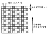
도 7a는 본 발명의 전자 사진용 도전성 부재를 이용하여 얻어진 화상의 평가에 사용하는 화상 출력 패턴의 개략도이다.
도 7b는 본 발명의 전자 사진용 도전성 부재를 이용하여 얻어진 화상의 평가에 사용하는 화상 출력 패턴의 개략도이다.
도 7c는 본 발명의 전자 사진용 도전성 부재를 이용하여 얻어진 화상의 평가에 사용하는 화상 출력 패턴의 개략도이다.
도 8은 본 발명의 전자 사진용 도전성 부재를 이용한 프로세스 카트리지의 개략도이다.1A is a schematic view of an electrophotographic conductive member of the present invention.
1B is a schematic view of the electroconductive member for electrophotography of the present invention.
1C is a schematic view of an electrophotographic conductive member of the present invention.
FIG. 1D is a schematic view of an electrophotographic conductive member of the present invention. FIG.
2 is a schematic view of an image forming apparatus using the electrophotographic conductive member of the present invention.
3 is a schematic view of another image forming apparatus using the electrophotographic conductive member of the present invention.
4A is an explanatory diagram of a microphase separation structure that a block copolymer can take, and is a schematic diagram of a microphase separation structure in which an image of a spherical structure is formed.
4B is an explanatory diagram of a micro phase separation structure that a block copolymer can take, and is a schematic diagram of a micro phase separation structure in which an image of a cylinder phase structure is formed.
FIG. 5A is a schematic diagram of a micro-phase separation structure, which is a schematic diagram of a micro-phase separation structure in which an image of a structure with a coarse phase is formed. FIG.
5B is a schematic diagram of a micro phase separation structure, which is a schematic diagram of a micro phase separation structure in which an image of a lamella structure is formed.
6A is a schematic view of a resistance measuring method of the electrophotographic conductive member of the present invention.
6B is a schematic view of a resistance measuring method of the electrophotographic conductive member of the present invention.
7A is a schematic view of an image output pattern used for evaluation of an image obtained using the electrophotographic conductive member of the present invention.
7B is a schematic view of an image output pattern used for evaluation of an image obtained by using the electrophotographic conductive member of the present invention.
7C is a schematic view of an image output pattern used for evaluation of an image obtained by using the electrophotographic conductive member of the present invention.
8 is a schematic view of a process cartridge using the electrophotographic conductive member of the present invention.
도 1a는 본 발명에 따른 도전성 롤러의 축에 직교하는 방향의 단면을 나타내고, 도 1b는 축방향의 단면을 나타낸다. 도전성 부재는 도전성 지지체(1)와 그 외주에 형성된 탄성층(2)을 포함하여 이루어진다.Fig. 1A shows a cross section in a direction perpendicular to the axis of the conductive roller according to the present invention, and Fig. 1B shows a cross section in the axial direction. The conductive member includes the
<지지체><Support>
지지체(1)는 도전성을 갖고, 그 위에 형성되는 도전성 탄성층을 지지하는 것이다. 재질로서는 예를 들어 철, 알루미늄, 티타늄, 구리 및 니켈 등의 금속이나 그들의 합금을 들 수 있다.The
<탄성층><Elastic Layer>
탄성층(2)은 비이온 도전성 블록(이후, 「A 블록」이라고 칭함) 및 이온 교환기를 갖는 이온 도전성 블록(이후, 「B 블록」이라고 칭함)의 2종의 중합체 블록을 포함하여 이루어지는 A-B-A형 블록 공중합체를 포함한다.The
이 블록 공중합체는 열가소성 엘라스토머이고, A 블록이 구상 구조, 실린더 구조 및 공연속 구조를 포함하여 이루어지는 군에서 선택되는 어느 하나의 구조를 이루고 있고, 또한 B 블록이 그 매트릭스를 이루고 있다.The block copolymer is a thermoplastic elastomer, and the A block has any one structure selected from the group consisting of a spherical structure, a cylinder structure and a coarse structure, and the B block forms the matrix.
본 발명에 따른 A-B-A형 블록 공중합체는 이온 도전성 블록 중에 이온 교환기를 가짐으로써 이온 전도성을 나타낸다. 또한, 이온 교환기는 분자의 주쇄에 공유 결합을 개재하여 직접 결합하고 있다. 그로 인해, 도전성 부재에 대하여 장기간에 걸쳐 직류 전압을 인가한 경우에 있어서의 이온 교환기의 탄성층 중의 이동이 제한되고, 도전성 부재의 전기 저항의 경시적인 상승을 억제할 수 있다.The A-B-A type block copolymer according to the present invention exhibits ionic conductivity by having an ion-exchange group in the ion-conductive block. The ion exchanger is directly bonded to the main chain of the molecule through a covalent bond. As a result, movement of the ion exchanger in the elastic layer when the direct current voltage is applied to the conductive member over a long period of time is limited, and the increase in the electrical resistance of the conductive member over time can be suppressed.
또한, 특허문헌 1에 기재된 바와 같이 우레탄 고무 등의 바인더 고무 중에 이온 도전제를 첨가하는 경우, 바인더 고무에 용해하는 이온 도전 재료량은 바인더 고무와 이온 도전제의 종류에 따라 정해지기 때문에, 포화 용해량 이상의 이온 도전제는 용해하지 않는다. 그 결과, 포화 용해량 이상의 이온 도전제를 바인더 고무에 첨가하여도 이온 도전제끼리가 응집할 뿐, 도전성 롤러로서 달성 가능한 저항값에 한계가 있는 경우가 있다. 한편, 본 발명과 같이 이온 교환기를 갖는 중합체 블록을 포함하여 이루어지는 B 블록을 분자 내에 갖는 A-B-A형 블록 공중합체를 바인더로서 이용하는 경우에는, 그 첨가량의 증가에 수반하는 응집이 탄성층 중에는 발생하지 않는다.In addition, as described in
<B 블록><B block>
본 발명에 따른 B 블록이 갖는 이온 교환기의 구체예를 이하에 든다. 술폰산기(-SO3H), 카르복실기, 인산기(H2PO4-), 아인산기 등. 그 중에서도 탄성층에 고도전성을 부여할 수 있는 점에서, 술폰산기, 인산기 또는 카르복실기가 바람직하다. 이들 중에서도 술폰산기가 특히 바람직하게 이용된다.Specific examples of the ion exchanger of the B block according to the present invention are described below. A sulfonic acid group (-SO 3 H), a carboxyl group, a phosphoric acid group (H 2 PO 4 -), a phosphorous acid group and the like. Of these, a sulfonic acid group, a phosphoric acid group or a carboxyl group is preferable in that high elasticity can be imparted to the elastic layer. Among them, a sulfonic acid group is particularly preferably used.
B 블록에 결합된 이온 교환기의 함유량에 따라, 도전성 부재로서 사용할 때에 바람직한 전기 저항값인 1×10² 내지 1×10¹¹Ω·cm의 범위 내에 탄성층의 전기 저항값을 조정할 수 있다. 상기 범위에 전기 저항값을 조정하기 위한 이온 도전성 블록에 대한 이온 교환기량은 10 내지 30몰%, 바람직하게는 15 내지 25몰%이다. 이온 교환기의 도입량에 대해서는 프로톤 NMR을 이용함으로써 용이하게 측정 가능하다.The electric resistance value of the elastic layer can be adjusted within a range of 1 x 10 2 to 1 x 10 11 ? Cm m, which is preferable electrical resistance value when used as a conductive member, according to the content of the ion exchanger bonded to the B block. The amount of the ion exchanger for the ion-conductive block for adjusting the electric resistance value in the above range is 10 to 30 mol%, preferably 15 to 25 mol%. The introduction amount of the ion exchanger can be easily measured by using proton NMR.
이온 교환기의 도입 방법으로서, 예를 들어 이온 교환기가 술폰산기이고 또한 이온 도전성 블록의 주쇄가 디엔계 중합체인 경우, 블록 공중합체의 디클로로메탄 용액을 제조하고, 이 용액에 황산을 첨가한다. 이렇게 함으로써 이중 결합에 대하여 선택적으로 술폰산기를 도입할 수 있다.As a method for introducing an ion-exchange group, for example, when the ion-exchange group is a sulfonic acid group and the main chain of the ion-conductive block is a dienic polymer, a dichloromethane solution of a block copolymer is prepared and sulfuric acid is added to this solution. By doing so, the sulfonic acid group can be selectively introduced into the double bond.
또한, 도전성 부재로서 양호한 방전 특성을 얻기 위해서는 도전성 부재와 피대전체의 사이에서 안정적인 닙을 형성할 필요가 있고, 본 발명의 A-B-A형 블록 공중합체는 열가소성 엘라스토머로서 고무 탄성을 나타낼 필요가 있다. 그 때문에, B 블록인 이온 도전성 블록의 유리 전이 온도는 10℃ 이하, 바람직하게는 0℃ 이하이다.Further, in order to obtain good discharge characteristics as a conductive member, it is necessary to form a stable nip between the conductive member and the charging member, and the A-B-A type block copolymer of the present invention needs to exhibit rubber elasticity as a thermoplastic elastomer. Therefore, the glass transition temperature of the ion-conductive block as the B block is 10 占 폚 or lower, preferably 0 占 폚 or lower.
상기 조건을 만족하는 B 블록으로서는 이하의 중합체를 들 수 있다. 폴리부타디엔, 폴리이소프렌, 폴리에틸렌부타디엔, 폴리에틸렌프로필렌, 폴리이소부틸렌, 폴리아크릴산, 말레산 변성 폴리에틸렌부타디엔(M-PEB), 말레산 변성 폴리에틸렌프로필렌(M-PEP), 말레산 변성 폴리에틸렌에틸렌프로필렌(M-PEEP), 말레산 폴리이소부틸렌As the B block satisfying the above conditions, the following polymers may be mentioned. (M-PEB), maleic acid-modified polyethylene propylene (M-PEP), maleic acid-modified polyethylene, ethylene propylene (M), polybutene -PEEP), maleic acid polyisobutylene
B 블록은 하기 화학식 1 내지 3으로 표시되는 구성 단위를 포함하여 이루어지는 군에서 선택되는 적어도 1개의 구성 단위를 갖는 것이 바람직하다.It is preferable that the B block has at least one constituent unit selected from the group consisting of constitutional units represented by the following formulas (1) to (3).
[화학식 1][Chemical Formula 1]

[화학식 2](2)

[화학식 3](3)

화학식 1 내지 3에 있어서, X는 각각 독립적으로 수산기(-OH) 또는 술폰산기(-SO3H)를 나타내고, Y는 각각 독립적으로 수산기 또는 술폰산기를 나타내고, Z는 각각 독립적으로 수소 원자 또는 메틸기를 나타낸다. 또한, X가 술폰산기인 경우, Y는 수산기이고, X가 수산기인 경우, Y는 술폰산기이다.X is independently a hydroxyl group (-OH) or a sulfonic acid group (-SO 3 H), Y is each independently a hydroxyl group or a sulfonic acid group, and each Z is independently a hydrogen atom or a methyl group . When X is a sulfonic acid group, Y is a hydroxyl group, and when X is a hydroxyl group, Y is a sulfonic acid group.
또한, B 블록은 하기 화학식 4 내지 6으로 표시되는 구성 단위를 포함하여 이루어지는 군에서 선택되는 적어도 1개의 구성 단위를 갖는 것이 바람직하다.The B block preferably has at least one structural unit selected from the group consisting of structural units represented by the following formulas (4) to (6).
[화학식 4][Chemical Formula 4]

[화학식 5][Chemical Formula 5]

[화학식 6][Chemical Formula 6]

화학식 4 내지 6에 있어서, X는 각각 독립적으로 카르복실기 또는 수소 원자를 나타내고, Y는 각각 독립적으로 카르복실기 또는 수소 원자를 나타내고, Z는 각각 독립적으로 수소 원자 또는 메틸기를 나타낸다. 또한, X가 카르복실기인 경우, Y는 수소 원자이고, X가 수소 원자인 경우, Y는 카르복실기 또는 수소 원자이다.In formulas (4) to (6), each X independently represents a carboxyl group or a hydrogen atom, each Y independently represents a carboxyl group or a hydrogen atom, and each Z independently represents a hydrogen atom or a methyl group. When X is a carboxyl group, Y is a hydrogen atom, and when X is a hydrogen atom, Y is a carboxyl group or a hydrogen atom.
또한, B 블록은 하기 화학식 7 및 하기 화학식 8로 표시되는 구성 단위를 갖는 직쇄 고분자 블록인 것이 바람직하다.The B block is preferably a linear polymer block having a structural unit represented by the following general formula (7) and (8).
[화학식 7](7)

[화학식 8][Chemical Formula 8]

화학식 7 중, R은 탄소수 2 이상 4 이하의 2가의 포화 탄화수소기를 나타낸다.In formula (7), R represents a divalent saturated hydrocarbon group having 2 to 4 carbon atoms.
<A 블록><A block>
본 발명에 따른 A-B-A형 블록 공중합체에 있어서 A 블록은 비이온 도전성 블록이다. 상기 A 블록은 본 발명에 따른 A-B-A형 블록 공중합체로 구성되어 이루어지는 열가소성 엘라스토머의 가교점으로서 작용한다. 그리고, 본 발명에 따른 탄성층 중에는 B 블록을 포함하여 이루어지는 매트릭스 상 중에 가교점이 되는 A 블록을 포함하여 이루어지는 구상 구조, 실린더상 구조 또는 공연속 구조 중 어느 하나의 구조를 갖는 상이 마이크로하게 분산되어 있다.In the A-B-A type block copolymer according to the present invention, the A block is a non-ionic conductive block. The A block acts as a crosslinking point of the thermoplastic elastomer composed of the A-B-A type block copolymer according to the present invention. In the elastic layer according to the present invention, a phase having any one of a spherical structure, a cylinder-shaped structure and a co-accelerated structure comprising an A block which is a crosslinking point in a matrix phase comprising a B block is micro-dispersed .
그 때문에, 탄성층의 강도가 향상되고, 탄성층에 대한 불가역적인 변형, 즉 압축 영구 왜곡의 발생이 유효하게 억제된다.As a result, the strength of the elastic layer is improved, and irreversible deformation of the elastic layer, that is, occurrence of compression set distortion is effectively suppressed.
상기한 이유로부터, 본 발명에 따른 A 블록으로서는 상온에서도 변형이 발생하기 어려운 중합체를 구성할 수 있는 블록인 것이 바람직하다. 구체적으로는 융점 또는 유리 전이 온도가 실온보다도 높은 것이 바람직하다.For the above reasons, it is preferable that the A block according to the present invention is a block capable of forming a polymer which is less likely to be deformed even at room temperature. Specifically, it is preferable that the melting point or the glass transition temperature is higher than the room temperature.
이러한 A 블록의 바람직한 예로서는 하기 화학식 9 내지 11로 표시되는 구성 단위를 포함하여 이루어지는 군에서 선택되는 적어도 1개의 구성 단위를 들 수 있다.Preferable examples of such A block include at least one structural unit selected from the group consisting of structural units represented by the following general formulas (9) to (11).
[화학식 9][Chemical Formula 9]

[화학식 10][Chemical formula 10]

[화학식 11](11)

상기한 바와 같은 A 블록 및 B 블록으로 구성되는 본 발명에 따른 A-B-A형 블록 공중합체는 이종 고분자인 A 블록과 B 블록의 사이에 척력 상호 작용(repulsive interaction)이 작용하고, 동종의 고분자쇄끼리로 응집하여 상 분리한다. 그러나, 이종 분자쇄 간의 연결성 때문에 각각의 고분자쇄의 확대보다 큰 상 분리 구조를 만들 수 없고, 결과적으로 수 나노미터 내지 수백 나노미터의 주기적인 자기 조직화 구조(self-assembled structure)를 만든다.In the ABA type block copolymer according to the present invention composed of the A block and the B block as described above, a repulsive interaction acts between the A block and the B block, which are heteropolymers, Coagulate and phase separate. However, due to the intermolecular chain linkage, it is not possible to make a larger phase-separated structure than the expansion of each polymer chain, resulting in a periodic self-assembled structure of several nanometers to several hundred nanometers.
이러한 구조를 마이크로 상 분리 구조(microphase-separated structure)라고 칭한다.This structure is called a microphase-separated structure.
Bates, F. S.; Fredrickson, G. H.; Annu. Res. Phys. Chem. 1990 (41) 525는, 블록 공중합체에 의해 형성되는 마이크로 상 분리 구조로서, 한쪽 중합체 블록을 포함하여 이루어지는 매트릭스 중에 다른 쪽 중합체 블록을 포함하여 이루어지는 구상 구조, 실린더상 구조, 공연속 구조 또는 라멜라상 구조를 갖는 상이 존재하는 것을 개시하고 있다.Bates, F. S .; Fredrickson, G. H .; Annu. Res. Phys. Chem. 1990 (41) 525 discloses a micro phase-separated structure formed by a block copolymer. The microcups separated structure includes a spherical structure comprising a polymer block in the other, a cylinder-shaped structure, a co- ≪ / RTI > structure.
도 4a, 4b, 5a 및 5b에 A-B-A형 블록 공중합체가 형성하는 마이크로 상 분리 구조의 모식도를 나타낸다. 이들 도면에 있어서, 41은 B 블록을 포함하여 이루어지는 매트릭스 상을 나타내고, 42는 A 블록을 포함하여 이루어지는 상을 나타낸다. 그리고, 도 4a는 A 블록을 포함하여 이루어지는 상이 구상 구조를 갖는 마이크로 상 분리 구조를 나타내고, 도 4b는 A 블록을 포함하여 이루어지는 상이 실린더 구조를 갖는 마이크로 상 분리 구조를 나타낸다. 또한, 도 5a는 A 블록을 포함하여 이루어지는 상이 공연속 구조를 갖는 마이크로 상 분리 구조를 나타내고, 또한 도 5b는 A 블록을 포함하여 이루어지는 상이 라멜라 구조를 갖는 마이크로 상 분리 구조를 나타낸다.4A, 4B, 5A and 5B show schematic diagrams of the microphase separation structure formed by the A-B-A type block copolymer. In these figures,
또한, 블록 공중합체의 마이크로 상 분리 구조에 대해서는 투과형 전자 현미경(TEM)에 의한 직접 구조 관찰이나 소각 X선 산란(SAXS) 측정에 의한 결정 구조 해석을 행함으로써 특정 가능하다. 예를 들어 TEM 관찰의 경우, 본 발명에 이용하는 A-B-A형 블록 공중합체는 이온 교환기를 갖는 B 블록이 친수성이고, 비이온 도전성 블록인 A 블록이 소수성이기 때문에, 인텅스텐산 등의 친수성 염색제를 이용하면, 이하와 같이 관찰된다.The microphase separation structure of the block copolymer can be specified by conducting a direct structural observation with a transmission electron microscope (TEM) or a crystal structure analysis by measurement of incineration X-ray scattering (SAXS). For example, in the case of TEM observation, since the AB block copolymer used in the present invention is hydrophilic in the B block having an ion-exchange group and the A block in the non-ion conductive block is hydrophobic, if a hydrophilic dye such as tungstic acid is used , It is observed as follows.
즉, TEM 관찰시에 B 블록이 상대적으로 어둡고, A 블록이 상대적으로 밝게 관찰된다. 따라서, B 블록이 구상 구조, 실린더상 구조 또는 공연속 구조의 어느 하나의 구조를 갖는 상을 갖는 마이크로 상 분리 구조를 형성하고, A 블록이 연속상인 것을 식별하는 것이 가능하다.That is, at the time of TEM observation, the B block is relatively dark and the A block is relatively brightly observed. Therefore, it is possible to form a micro phase-separated structure in which the B block has an image having a structure of any one of a spherical structure, a cylindrical phase structure, or a coercive field structure, and to identify that the A block is a continuous phase.
본 발명에 따른 탄성층 중에 있어서, A-B-A형 블록 공중합체가 도 4a, 도 4b 또는 도 5a에 나타내는 구상 구조, 실린더상 구조 또는 구상 구조를 갖는 A 블록을 포함하여 이루어지는 상이, 이온 전도에 기여하는 B 블록을 포함하여 이루어지는 연속상 중에 존재하여 이루어지는 마이크로 상 분리 구조를 구성하고 있다. 이와 같이 이온 전도에 기여하는 이온 교환기를 갖는 B 블록이 연속상을 구성함으로써, 본 발명에 따른 탄성층은 양호한 도전성을 나타내게 된다.In the elastic layer according to the present invention, the ABA type block copolymer comprises an A block having a spherical structure, a cylinder-like structure or a spherical structure shown in Fig. 4A, 4B or 5A, Block is present in the continuous phase including the micro-phase separation structure. As described above, since the B block having an ion exchanger contributing to ion conduction forms a continuous phase, the elastic layer according to the present invention exhibits good conductivity.
전술한 바와 같은 마이크로 상 분리 구조는 A 블록과 B 블록의 체적비를 제어함으로써 형성할 수 있다. 구체적으로는 A 블록과 B 블록의 체적 분율을 A 블록/B 블록=10/90 내지 A 블록/B 블록=40/60, 보다 바람직하게는 A 블록/B 블록=15/85 내지 A 블록/B 블록=38/62로 하면 된다.The micro phase separation structure as described above can be formed by controlling the volume ratio of the A block and the B block. Specifically, the volume fraction of the A block and the B block is defined as A block / B block = 10/90 to A block / B block = 40/60, more preferably A block / B block = 15/85 to A block / B Block = 38/62.
또한, A-B-A형 블록 공중합체의 분자량에 대해서는 마이크로 상 분리 구조가 형성되는 조건에 있어서 특별히 제약되는 것이 아니다. 단, 분자량이 높을수록 막 강도가 상승하기 때문에 여기서는 분자량이 10,000 이상인 것이 바람직하다.The molecular weight of the A-B-A type block copolymer is not particularly limited in the condition that the micro phase separation structure is formed. However, the higher the molecular weight, the higher the film strength. Therefore, the molecular weight is preferably 10,000 or more.
이 블록 공중합체는 리빙 중합법에 의해 합성되기 때문에, 중합체 자신의 분자량 분포가 매우 좁고, 저분자량의 올리고머나 중합체가 거의 생성되지 않고, 그들이 전기 저항의 변동에 기여하는 일은 없다. 또한, 본 발명의 A-B-A형 블록 공중합체에는 발명의 효과를 현저하게 손상시키지 않는 범위 내에서 필요에 따라 고무의 배합제로서 일반적으로 이용되고 있는 충전제, 연화제, 가공 보조제, 점착 부여제, 분산제, 발포제 등을 첨가할 수 있다. 또한, 목적에 따라 탄성층의 외주에 새로운 탄성층, 도전성 탄성 표층(도 1c 및 도 1d 참조)이나 보호층을 형성할 수도 있다.Since this block copolymer is synthesized by a living polymerization method, the molecular weight distribution of the polymer itself is very narrow, and oligomers and polymers of low molecular weight are hardly produced, and they do not contribute to variation of electric resistance. The ABA type block copolymer of the present invention may further contain additives such as fillers, softeners, processing aids, tackifiers, dispersants, foaming agents, and the like, which are generally used as a compounding agent of rubber within a range not significantly impairing the effects of the present invention Etc. may be added. In addition, a new elastic layer, a conductive elastic surface layer (see FIG. 1C and FIG. 1D) and a protective layer may be formed on the outer periphery of the elastic layer in accordance with the purpose.
본 발명에 있어서 이온 교환기의 치환량은 탄성층의 체적 저항률이 다음 3가지 각 환경 중에서 중 저항 영역(체적 저항률이 1×10² 내지 1×10¹¹Ω·cm)이 되도록 하는 양이 바람직하다.In the present invention, the substitution amount of the ion exchange group is preferably such that the volume resistivity of the elastic layer is in the middle resistance region (volume resistivity is 1 x 10 2 to 1 x 10 11 ? Cm) in each of the following three environments.
·저온 저습(L/L) 환경(온도 15℃, 상대 습도 10%).· Low temperature and low humidity (L / L) environment (temperature 15 ℃,
·상온 상습(N/N) 환경(온도 23℃, 상대 습도 55%).· Normal temperature (N / N) environment (temperature 23 ℃, relative humidity 55%).
·고온 고습(H/H) 환경(온도 30℃, 상대 습도 80%).· High temperature and high humidity (H / H) environment (
<<탄성층의 성형 방법>><< Molding method of elastic layer >>
탄성층의 성형 방법으로서는 예를 들어 압출 성형이나 사출 성형, 압축 성형 등의 공지된 방법을 들 수 있다. 즉, 상기 열가소성 엘라스토머를 가열하여 임의의 형상으로 성형하고, 냉각함으로써 탄성층을 형성하는 방법이다. 또한, 탄성층은 도전성 지지체 상에 직접 열가소성 엘라스토머를 성형하여 제작하여도 되고, 튜브 형상으로 성형한 열가소성 엘라스토머를 도전성 지지체에 피복시켜도 된다. 또한, 탄성층의 제작 후에 표면을 연마하여 형상을 정돈하여도 된다.Examples of the method of forming the elastic layer include known methods such as extrusion molding, injection molding, and compression molding. That is, the thermoplastic elastomer is heated to form an arbitrary shape and then cooled to form an elastic layer. Further, the elastic layer may be formed by molding a thermoplastic elastomer directly on the conductive support, or the thermoplastic elastomer formed into a tube shape may be coated on the conductive support. Further, the surface may be polished after the production of the elastic layer to arrange the shape.
탄성층의 형상은 완성된 대전 부재와 전자 사진 감광체의 접촉 닙 폭이 대전 부재의 길이 방향의 분포로 가능한 한 균일해지도록, 전자 사진용 도전성 부재의 전자 사진 감광체측 중앙부의 형상이 단부보다도 전자 사진 감광체측에 볼록하게 되어 있는 것이 바람직하다. 전자 사진용 도전성 부재의 형상이 롤러 형상인 경우에는 롤러 중앙부의 직경이 단부의 직경보다도 큰 크라운 형상으로 되어 있는 것이 바람직하다. 또한, 완성된 전자 사진용 도전성 부재의 접촉 닙 폭이 균일해지기 위해서, 전자 사진용 도전성 부재의 요동이 작은 편이 바람직하다.The shape of the elastic layer is preferably such that the shape of the central portion on the electrophotographic photosensitive member side of the electrophotographic conductive member is made to be more electrophotographic than the end portion so that the contact nip width between the completed charging member and the electrophotographic photosensitive member becomes as uniform as possible in the longitudinal direction distribution of the charging member. And is convex on the photoconductor side. When the shape of the electrophotographic conductive member is a roller shape, it is preferable that the diameter of the center portion of the roller is larger than the diameter of the end portion. In addition, in order to make the contact nip width of the finished electrophotographic conductive member uniform, it is preferable that the fluctuation of the electrophotographic conductive member is small.
<전자 사진용 도전성 부재의 전기 저항>≪ Electrical resistance of electroconductive conductive member &
전자 사진용 도전성 부재의 전기 저항은 H/H 환경 중에서는 1×10⁴Ω 이상, L/L 환경 중에서는 1×10⁸Ω 이하인 것이 바람직하다. 또한, N/N 환경 중에서는 2×10⁴Ω 이상 6×10⁷Ω 이하인 것이 바람직하다. L/L 환경 중의 전기 저항을 상기한 값 이하로 함으로써, 전자 사진용 도전성 부재 내부에서의 전압 강하가 억제되고, 전자 사진 감광체를 원하는 값으로 균일하게 대전하는 것이 가능해지므로 바람직하다. 또한, 고온 고습 환경 중의 저항이 상기 범위보다 크면, 전자 사진 감광체가 깎여 바탕의 금속이 드러나더라도 인가 전류가 누설하지 않고, 하프톤 화상 상에 대전의 농도 불균일이 나타나는 일이 없으므로 바람직하다.The electric resistance of the electrophotographic conductive member is preferably 1 x 10 4 ? Or more in an H / H environment and 1 x 10 8 ? Or less in an L / L environment. In addition, in the N / N environment, it is preferable that it is not less than 2 x 10 4 ? And not more than 6 x 10 7 ?. When the electric resistance in the L / L environment is made to be equal to or lower than the above value, the voltage drop inside the electrophotographic conductive member is suppressed, and it is possible to uniformly charge the electrophotographic photosensitive member to a desired value. If the resistance in the high temperature and high humidity environment is larger than the above range, the applied current does not leak even when the electrophotographic photosensitive member is shaved and the metal of the background is exposed, so that the unevenness of charging on the halftone image does not appear.
전자 사진용 도전성 부재가 롤러 형상이 아닌 경우에는 1cm2당 저항으로 나타낸다. 이 경우, 전자 사진용 대전 부재 표면에 1cm2의 금속 전극을 증착하고, 전압을 인가하여 흐르는 전류를 측정함으로써 저항을 구한다.When the conductive member for electrophotography is not in the form of a roller, it is expressed as a resistance per 1 cm 2 . In this case, a metal electrode of 1 cm 2 is deposited on the surface of the charging member for electrophotography, and a current is measured by applying a voltage to obtain a resistance.
(전자 사진 장치)(Electrophotographic apparatus)
도 2에 본 발명에 따른 도전성 부재의 하나의 실시 형태인 대전 부재를 대전 롤러(6)로서 이용한 전자 사진 화상 형성 장치를 나타낸다. 상 담지체인 전자 사진 감광체 드럼(5)은 화살표 방향으로 회전하면서 대전 롤러(6)에 의해 1차 대전되고, 다음에 도시하지 않은 노광 수단으로부터의 노광광(11)에 의해 정전 잠상이 형성된다. 현상제 용기(31) 중의 현상제는 현상 롤러(12)와 현상 블레이드(30)의 사이에서 마찰되어 대전되면서 현상 롤러(12)의 표면에 담지되어 전자 사진 감광체 드럼(5)의 표면에 반송된다. 그 결과, 정전 잠상은 현상되고, 토너상이 형성된다.Fig. 2 shows an electrophotographic image forming apparatus using a charging member, which is one embodiment of the electroconductive member according to the present invention, as the charging roller 6. Fig. The electrophotographic
토너상은 전사 롤러(8)와 전자 사진 감광체 드럼(5)의 사이에 있어서 기록 미디어(7)에 전사되고, 그 후 정착부(9)에 있어서 정착된다. 전사되지 않고 전자 사진 감광체(5)의 표면에 잔류한 토너는 클리닝 블레이드(10)에 의해 회수된다. 현상 롤러(12), 대전 롤러(6), 전사 롤러(8) 등에는 화상 형성 장치의 전원(18, 20, 22)으로부터 각각 전압이 인가되어 있다.The toner image is transferred to the
여기서, 대전 롤러(6)에는 전원(20)으로부터 직류 전압이 인가된다. 인가 전압에 직류 전압을 이용함으로써 전원의 비용을 낮게 억제할 수 있다는 이점이 있다. 또한, 대전음이 발생하지 않는다는 이점이 있다. 인가하는 직류 전압의 절댓값은 공기의 방전 개시 전압과 피대전체 표면(전자 사진 감광체 표면)의 1차 대전 전위의 합으로 하는 것이 바람직하다. 통상, 공기의 방전 개시 전압은 600 내지 700V 정도, 전자 사진 감광체 표면의 1차 대전 전위는 300 내지 800V 정도이므로, 구체적인 1차 대전 전압으로서는 900 내지 1500V로 하는 것이 바람직하다.Here, DC voltage is applied to the charging roller 6 from the
또한, 전자 사진 화상 형성 장치는 도 3에 도시한 바와 같이 화상 형성에 필요한 부재를 4색분 구비한 컬러 전자 사진 화상 형성 장치로 하여도 된다. 기록 미디어(7)가 화살표 방향으로 이동하는 동안에 토너상이 전자 사진 감광체 드럼(5d)과 전사 롤러(8d)의 사이, 전자 사진 감광체 드럼(5c)과 전사 롤러(8c)의 사이, 전자 사진 감광체 드럼(5b)과 전사 롤러(8b)의 사이, 전자 사진 감광체 드럼(5a)와 전사 롤러(8a)의 사이에서 차례로 전사된다. 기록 미디어(7)에 전사된 토너상은 정착부(9)에 있어서 정착된다. 대전 롤러(6a, 6b, 6c, 6d)는 각각 전자 사진 감광체 드럼(5a, 5b, 5c, 5d)을 대전한다. 컬러 전자 사진 화상을 형성하기 위해서는 통상 시안, 옐로우, 마젠타, 블랙의 4색의 토너를 사용한다. 4색의 토너는 기록 미디어(7)에 대하여 임의의 순서로 전사하면 된다.The electrophotographic image forming apparatus may be a color electrophotographic image forming apparatus having four colors of members required for image formation as shown in Fig. The toner image is transferred between the electrophotographic
(프로세스 카트리지)(Process cartridge)
또한, 도 8은 본 발명에 따른 전자 사진용 도전성 부재를 대전 롤러(302)에 적용한 프로세스 카트리지의 개략 단면도이다. 도 8에 도시한 바와 같이, 본 발명에 따른 프로세스 카트리지는 전자 사진 감광체(301), 대전 롤러(302), 현상 장치(303) 및 클리닝 장치(307) 등이 일체화되고, 전자 사진 장치의 본체에 착탈 자재(착탈 가능)로 구성되어 있다.8 is a schematic cross-sectional view of the process cartridge in which the electroconductive member for electrophotography according to the present invention is applied to the charging
<실시예><Examples>
이하에 본 발명에 따른 도전성 부재에 대하여 실시예를 들어 더욱 상세하게 설명한다. 또한, 각 실시예 및 비교예에 관한 도전성 롤러의 전기 저항의 측정 방법 및 표면 조도의 측정 방법은 이하와 같다.Hereinafter, the conductive member according to the present invention will be described in more detail with reference to examples. The methods of measuring electric resistance and measuring the surface roughness of the conductive roller according to each of the Examples and Comparative Examples are as follows.
<도전성 롤러의 전기 저항의 측정 방법>≪ Method of measuring electrical resistance of conductive roller &
도 6a, 6b에 도시한 바와 같이 전자 사진 장치에 이용한 경우의 사용 상태와 마찬가지의 응력으로 전자 사진 감광체와 동일한 곡률의 원기둥형 금속(32)에 접촉시켜 통전하였을 때의 저항을 측정한다. 도 6a에 있어서 33a와 33b는 추에 고정된 베어링이고, 도전성 기층 부재(40)의 도전성 지지체(1)의 양단에 연직 하측 방향에 누르는 응력을 인가한다. 도전성 기층 부재(40)의 연직 하측 방향에는 도전성 기층 부재(40)와 평행하게 원기둥형 금속(32)이 배치되어 있다. 그리고, 도시하지 않은 구동 장치에 의해 원기둥형 금속(32)을 회전시키면서, 도 6b와 같이 도전성 기층 부재(40)를 베어링(33a와 33b)을 이용하여 원기둥형 금속(32)에 밀어 붙인다. 사용 상태의 전자 사진 감광체 드럼과 마찬가지의 회전 속도로 원기둥형 금속(32)을 회전시키고, 도전성 기층 부재(40)를 종동 회전시키면서 전원(34)으로부터 직류 전압-200V를 인가하고, 원기둥형 금속(32)으로부터 흘러 나오는 전류를 전류계(A)로 측정한다. 이때의 인가 전압과 측정된 전류로부터 계산하여 도전성 기층 부재(40)의 전기 저항을 산출한다. 본 실시예에서는 도전성 지지체(1)의 양단에 각각 5N의 힘을 가하여 직경 30mm의 원기둥형 금속(32)에 접촉시키고, 원기둥형 금속(32)의 주속 150mm/초로 회전시켰다.As shown in Figs. 6A and 6B, the resistance is measured when it is energized in contact with the
<도전성 롤러의 표면 조도의 측정 방법>≪ Method of measuring surface roughness of conductive roller &
도전성 기층의 표면 조도로서는 10점 평균 조도(Rz jis1994)로 50㎛ 이하, 특히는 30㎛ 이하, 나아가서는 20㎛ 이하가 바람직하다. 표면 조도의 측정에는 표면 조도 측정 장치(상품명: 서프코더 SE3500, 고사카겐큐쇼제)를 사용하고, 선단 반경 2㎛의 다이아몬드로 만든 접촉 바늘을 이용하였다. 측정 조건은 JIS B0601: 1994에 기초하여 측정 스피드는 0.5mm/초, 컷오프 주파수 λc는 0.8mm, 기준 길이는 0.8mm, 평가 길이는 8.0mm로 하였다.The surface roughness of the conductive base layer is preferably 50 占 퐉 or less, particularly 30 占 퐉 or less, more preferably 20 占 퐉 or less, in 10-point average roughness (Rz jis1994). A surface roughness measuring apparatus (trade name: Surfcorder SE3500, manufactured by Kosaka Kenshin Co., Ltd.) was used to measure the surface roughness, and a contact needle made of diamond having a tip radius of 2 탆 was used. The measurement conditions were a measurement speed of 0.5 mm / sec, a cutoff frequency? C of 0.8 mm, a reference length of 0.8 mm, and an evaluation length of 8.0 mm based on JIS B0601: 1994.
<중합체 1의 합성>≪ Synthesis of
중합체 1을 리빙 음이온 중합법에 의해 합성하였다.
우선, 용량이 10리터인 내압 용기를 준비하고, 당해 내압 용기 내의 공기를 건조 아르곤으로 치환하였다. 계속해서, 분자체를 이용하여 정제한 스티렌 단량체 8.46g, 분자체를 이용하여 정제한 중합 용매로서의 시클로헥산 1.0L, 개시제로서의 sec-부틸리튬의 10wt% 헥산 용액 0.80g을 첨가하였다.First, a pressure-resistant container having a capacity of 10 liters was prepared, and air in the pressure-resistant container was replaced with dry argon. Subsequently, 8.46 g of the styrene monomer purified using molecular sieves, 1.0 L of cyclohexane as a polymerization solvent purified using molecular sieves, and 0.80 g of a 10 wt% hexane solution of sec-butyllithium as an initiator were added.
그리고, 아르곤 분위기 하에서 온도 50℃에서 4시간 중합을 행하였다. 4시간 후, 계속해서 활성 알루미나를 이용하여 정제한 부타디엔 단량체 41.08g과 이소프렌 단량체 42.00g을 첨가하고, 온도 50℃에서 2시간, 중합을 행하였다. 또한, 2시간 후, 분자체를 이용하여 정제한 스티렌 단량체 8.46g을 첨가하고, 온도 50℃에서 4시간 중합을 행하였다. 반응 종료 후, 반응 용액 내에 메탄올을 5.0L 첨가하고, 이것을 메탄올로 재침전함으로써, 스티렌 블록과, 부타디엔 및 이소프렌이 랜덤 공중합하여 이루어지는 블록과, 스티렌 블록을 포함하여 이루어지는 3원 공중합체 100g을 얻었다.Then, polymerization was carried out at 50 캜 for 4 hours in an argon atmosphere. After 4 hours, 41.08 g of a butadiene monomer purified by using activated alumina and 42.00 g of an isoprene monomer were added and polymerization was carried out at a temperature of 50 ° C for 2 hours. Further, after 2 hours, 8.46 g of the purified styrene monomer was added by molecular sieves, and polymerization was carried out at 50 ° C for 4 hours. After completion of the reaction, 5.0 L of methanol was added to the reaction solution, and this was re-precipitated with methanol to obtain 100 g of a ternary copolymer comprising a styrene block, a block formed by random copolymerization of butadiene and isoprene, and a styrene block.
이 3원 공중합체는 후술하는 표 1-2에 있어서는 「스티렌-부타디엔/이소프렌-스티렌」이라고 표기한다.This ternary copolymer is referred to as " styrene-butadiene / isoprene-styrene " in Table 1-2 to be described later.
얻어진 3원 공중합체의 GPC(겔 침투 크로마토그래피)에 의한 질량 평균 분자량 Mw는 8.0×10⁴이었다. 이것을 중합체 No. 1이라 한다.The mass-average molecular weight Mw of the obtained terpolymer obtained by GPC (gel permeation chromatography) was 8.0 × 10 4 . This is referred to as Polymer No. 1. 1.
중합체 No. 1의 스티렌 블록, 부타디엔과 이소프렌이 랜덤 공중합하여 이루어지는 블록 및 스티렌 블록의 체적 비율을 표 1-2에 나타낸다. 또한, 부타디엔과 이소프렌이 랜덤 공중합하여 이루어지는 블록 중에 있어서의 부타디엔과 이소프렌의 체적 비율도 표 1-2에 함께 나타낸다.Polymer No. Table 1 shows the volume ratios of the styrene block, the block formed by random copolymerization of butadiene and isoprene, and the styrene block. The volume ratios of butadiene and isoprene in the block formed by random copolymerization of butadiene and isoprene are also shown in Table 1-2.
<중합체 No. 2 내지 13, 19의 합성>≪ Polymer Nos. 2 to 13 and 19>
원료 및 개시제의 배합량을 표 1-1에 기재한 바와 같이 변경한 것 이외에는 중합체 No. 1과 마찬가지로 하여 중합체 No. 2 내지 13 및 중합체 No. 19를 합성하였다. 얻어진 중합체의 중량 평균 분자량, 각 블록의 체적 비율 및 부타디엔과 이소프렌이 랜덤 공중합하여 이루어지는 블록 중에 있어서의 부타디엔과 이소프렌의 체적 비율을 표 1-2에 나타낸다.Except that the blending amount of the raw material and the initiator was changed as shown in Table 1-1. 1). 2 to 13 and polymer No. 2. 19 were synthesized. Table 1-2 shows the weight average molecular weight of the obtained polymer, the volume ratio of each block, and the volume ratio of butadiene and isoprene in the block formed by random copolymerization of butadiene and isoprene.
[표 1-1][Table 1-1]

[표 1-2][Table 1-2]

<중합체 No. 14의 합성>≪ Polymer Nos. 14>
중합체 No. 14는 리빙 라디칼 중합법에 의해 합성하였다.Polymer No. 14 was synthesized by living radical polymerization.
우선, 질소 분위기하에서 브롬화 구리(Ⅰ) 0.28g, 헥사메틸트리에틸렌테트라아민 0.45g, 디메틸2,6-디브로모헵탄디오에이트 0.675g, tert-부틸아크릴레이트(tBA) 90.23g을 디메틸포름아미드(DMF) 중에서 혼합하였다. 그리고, 질소로 용존 산소를 치환한 후, 온도 70℃에서 반응을 행하였다.First, 0.28 g of copper (I) bromide, 0.45 g of hexamethyltriethylenetetraamine, 0.675 g of
계속해서, 얻어진 브롬을 양쪽 말단에 갖는 폴리tBA에 브롬화구리(Ⅰ) 0.06g, 헥사메틸트리에틸렌테트라아민 0.10g, 메틸메타크릴레이트 단량체 9.77g을 혼합, 질소 치환하였다. 온도 100℃에서 반응을 행한 후, 액체 질소로 급랭하고, 반응을 정지하였다. 그 후, 메탄올에 대한 재침전에 의한 정제에 의해 PMMA-b-PtBA-b-PMMA 트리블록 공중합체 100g을 얻었다.Subsequently, 0.06 g of copper (I) bromide, 0.10 g of hexamethyltriethylenetetraamine, and 9.77 g of methyl methacrylate monomer were mixed with poly tBA having the obtained bromine at both ends and replaced with nitrogen. After the reaction was carried out at a temperature of 100 占 폚, quenching with liquid nitrogen was carried out and the reaction was stopped. Thereafter, 100 g of a PMMA-b-PtBA-b-PMMA triblock copolymer was obtained by refining with methanol before reprecipitation.
계속해서, 얻어진 블록 공중합체를 클로로포름 중, 실온에서 트리플루오로아세트산 400g과 혼합함으로써 PtBA 세그먼트의 tert-부틸기의 탈보호 반응을 행하여 카르복실산으로 변환하였다. 이에 의해, PMMA-b-PAA(폴리아크릴산)-b-PMMA 트리블록 공중합체를 얻었다. 얻어진 트리블록 공중합체의 GPC에 의한 질량 평균 분자량은 4.0×10⁴이었다. 이것을 중합체 No. 14로 하였다.Subsequently, the obtained block copolymer was mixed with chloroform in 400 g of trifluoroacetic acid at room temperature to carry out the deprotection reaction of the tert-butyl group of the PtBA segment to convert it to a carboxylic acid. Thus, PMMA-b-PAA (polyacrylic acid) -b-PMMA triblock copolymer was obtained. The mass average molecular weight of the obtained triblock copolymer by GPC was 4.0 × 10 4 . This is referred to as Polymer No. 1. 14.
<중합체 No. 15 내지 18, 20의 합성>≪ Polymer Nos. Synthesis of 15 to 18, 20>
원료 및 개시제의 배합량을 표 2-1에 나타내는 바와 같이 변경한 것 이외에는 중합체 14와 마찬가지로 하여 중합체 No. 15 내지 18, 20을 합성하였다. 얻어진 중합체의 중량 평균 분자량 Mw 및 각 블록의 체적 비율을 표 2-1에 나타낸다.Polymer No. 2 was obtained in the same manner as in Polymer 14, except that the blending amounts of the raw material and the initiator were changed as shown in Table 2-1. 15 to 18, 20 were synthesized. The weight average molecular weight Mw of the obtained polymer and the volume ratio of each block are shown in Table 2-1.
[표 2-1][Table 2-1]

[표 2-2][Table 2-2]

[실시예 1][Example 1]
100g의 중합체 No. 1을 4.0리터의 디클로로메탄에 용해하고, 아르곤 분위기 중에서 액온을 40℃에 유지하였다. 27.52g의 농황산을 상기 디클로로메탄 용액에 적하하고, 적하 종료 후, 액온을 80℃로 승온하고, 액온 80℃를 유지하면서 72시간 교반하여 반응시켰다. 계속해서, 1.0리터의 메탄올을 상기 반응 용액 중에 적하하고, 반응을 정지하였다. 얻어진 반응물을 톨루엔 용해와 메탄올 재침전을 3회 반복하여 세정하고, 그 후, 대기 중에서 온도 80℃에서 24시간 건조시켰다. 이어서, 건조시킨 반응물을 1.0리터의 톨루엔에 용해하고, 질소 분위기 중에서 교반하면서 온도 120℃에서 건류하면서 500g의 p-톨루엔술포닐히드라진을 첨가하여 4시간 반응시키고, 디엔 유래의 이중 결합을 수소화하였다.100 g of the polymer No. < 1 was dissolved in 4.0 liters of dichloromethane, and the solution temperature was maintained at 40 占 폚 in an argon atmosphere. 27.52 g of concentrated sulfuric acid was added dropwise to the above dichloromethane solution. After completion of the dropwise addition, the liquid temperature was raised to 80 캜 and stirred for 72 hours while maintaining the liquid temperature at 80 캜. Subsequently, 1.0 liter of methanol was added dropwise to the reaction solution, and the reaction was terminated. The obtained reaction product was washed three times by repeating toluene dissolution and methanol re-precipitation, and then dried in the air at 80 DEG C for 24 hours. Subsequently, the dried reaction product was dissolved in 1.0 liter of toluene, 500 g of p-toluenesulfonylhydrazine was added while stirring at a temperature of 120 캜 with stirring in a nitrogen atmosphere, and the reaction was carried out for 4 hours to hydrogenate the diene-derived double bond.
얻어진 수소화물을 톨루엔에 용해하여 메탄올로 재침전하는 조작을 5회 반복하여 세정하고, 그 후 대기 중 80℃에서 24시간 건조시켜 실시예 1에 관한 열가소성 엘라스토머 No. 1을 얻었다.The obtained hydride was dissolved in toluene and reprecipitated with methanol was repeatedly washed five times, and then dried in the atmosphere at 80 占 폚 for 24 hours to obtain a thermoplastic elastomer No. 1 of Example 1. 1.
열가소성 엘라스토머 No. 1에 대하여 술폰화율을 프로톤 NMR로 측정한 결과, 디엔 블록의 이중 결합에 대하여 20mol%의 술폰산기가 도입되어 있는 것을 알았다.Thermoplastic elastomer No. 1, the sulfonation rate was measured by proton NMR, and it was found that 20 mol% of sulfonic acid group was introduced into the double bond of the diene block.
또한, 열가소성 엘라스토머 No. 1의 초박 절편을 동결 절편 절삭 장치(상품명: 크라이오울트라마이크로톰, 레이카마이크로시스템즈(주)사제)를 이용하여 잘라내고, 사산화루테늄으로 증기 염색하였다. 이 초박 절편을 투과형 전자 현미경(TEM)으로 관찰하고, 폴리스티렌 블록 성분이 구상의 마이크로 상 분리 구조를 형성하고 있는 것을 확인하였다.Further, the thermoplastic elastomer No. 1 was cut out using a freezing section cutting device (trade name: Cryo Ultramicrotome, manufactured by Reica Microsystems Co., Ltd.) and vapor-dyed with ruthenium tetraoxide. This ultrathin slice was observed with a transmission electron microscope (TEM), and it was confirmed that the polystyrene block component forms a spherical micro phase separation structure.
이어서, 코어 금속(직경 6mm, 길이 252mm, SUM22제, 무전해 니켈 도금 6㎛)을 중심부에 세팅한 최대 내경 8.6mm, 크라운 150㎛의 통 형상의 금형을 세팅한 트랜스퍼 금형에 열가소성 엘라스토머 No. 1을 세팅하였다. 그리고, 온도 240℃의 프레스기로 성형하고, 계속해서 냉각 프레스로 실온까지 냉각 후, 트랜스퍼 금형으로부터 롤러를 취출하고, 단부 직경 8.40mm, 중앙부 직경 8.55mm의 크라운 형상을 갖는 도전성 롤러 No. 1을 얻었다.Subsequently, a thermoplastic elastomer No. 1 was attached to a transfer mold in which a core metal (diameter 6 mm, length 252 mm, made of SUM22, electroless nickel plating 6 μm) was set at the center and a maximum inner diameter of 8.6 mm and a crown 150 μm was set. 1 was set. The roller was then taken out from the transfer mold, and a conductive roller No. 4 having a crown shape with an end diameter of 8.40 mm and a center diameter of 8.55 mm was obtained. 1.
<도전성 롤러의 평가>≪ Evaluation of conductive roller &
<<평가 (1)>><< Rating (1) >>
도전성 롤러 No. 1을 N/N 환경에 24시간 방치한 후, 마이크로 경도를 마이크로 고무 경도계(상품명: MD-1 capa 타입A, 고분자계기가부시키가이샤 제조)를 이용하여 측정하였다.Conductive roller No. 1 was allowed to stand in an N / N environment for 24 hours, and then the micro hardness was measured using a micro-rubber hardness meter (trade name: MD-1 capa type A, manufactured by Mitsubishi Chemical Corporation).
<<평가 (2)>><< Rating (2) >>
도전성 롤러 No. 1에 대하여 표면 조도(Rzjis)를 상기한 방법에 의해 측정하였다.Conductive roller No. 1, the surface roughness (Rzjis) was measured by the above-mentioned method.
<<평가 (3)>><< Rating (3) >>
도전성 롤러 No. 1의 전기 저항값을 상기한 방법에 의해 산출하였다.Conductive roller No. 1 was calculated by the above method.
<<평가 (4)>><< Rating (4) >>
전자 사진식 레이저 프린터로서 기록 미디어의 출력 스피드가 160mm/초, 화상의 해상도가 1200dpi인 전자 사진식 레이저 프린터를 준비하였다. 이 전자 사진식 레이저 프린터는 A4 크기의 종이를 세로 방향으로 반송 가능하다. 또한, 전자 사진 감광체는 알루미늄 실린더에 막 두께 16㎛의 유기 감광층이 형성된 반전 현상 방식의 전자 사진 감광체 드럼이다. 또한, 당해 전자 사진 감광체 드럼의 최외층은 변성 폴리아릴레이트 수지를 바인더 수지로 하는 전하 수송층을 포함하여 이루어진다.As an electrophotographic laser printer, an electrophotographic laser printer having an output speed of a recording medium of 160 mm / sec and an image resolution of 1200 dpi was prepared. This electrophotographic laser printer is capable of transporting A4 size paper in the longitudinal direction. The electrophotographic photosensitive member is an electrophotographic photosensitive drum of an inverted development type in which an organic photosensitive layer having a thickness of 16 mu m is formed on an aluminum cylinder. The outermost layer of the electrophotographic photosensitive drum comprises a charge transport layer having a modified polyarylate resin as a binder resin.
또한, 토너에는 왁스를 중심으로 하전 제어제와 색소 등을 포함하는 스티렌과 부틸아크릴레이트의 랜덤 공중합체를 중합시키고, 또한 표면에 폴리에스테르 박층을 중합시켜 실리카 미립자 등을 외첨한 유리 전이 온도 63℃, 질량 평균 입경 6.5㎛의 중합 토너이다. 이 전자 사진식 레이저 프린터에 도전성 롤러 No. 1을 대전 롤러로서 장착하였다. 그리고, 이 전자 사진식 레이저 프린터를 N/N 환경에 24시간 둔 후, N/N 환경 중에서 화상 출력하였다. 1차 대전 전압으로서 -1150V를 상기 대전 롤러에 인가하였다. 출력하는 화상 패턴은 하기 표 3에 기재된 (패턴 1) 내지 (패턴 5)의 5종류로 하였다.Also, toner was prepared by polymerizing a random copolymer of styrene and butyl acrylate containing a charge control agent and a dye, etc., centering on wax, and polymerizing a thin layer of polyester on the surface to obtain fine silica particles, , And a mass average particle diameter of 6.5 mu m. In this electrophotographic laser printer, 1 as a charging roller. Then, the electrophotographic laser printer was placed in an N / N environment for 24 hours, and then an image was output in an N / N environment. -1150 V as the primary charging voltage was applied to the charging roller. The image pattern to be output was classified into five types (pattern 1) to (pattern 5) described in Table 3 below.
[표 3][Table 3]

얻어진 화상 패턴에 대하여 육안으로 관찰하고, 대전 롤러에 기인하는 얼룩의 유무를 하기 표 4에 기재된 기준에 기초하여 평가하였다.The obtained image pattern was observed with naked eyes, and the presence or absence of a stain caused by the charging roller was evaluated based on the criteria described in Table 4 below.
[표 4][Table 4]

<<평가 (5)>><< Rating (5) >>
이어서, 상기 전자 사진식 레이저 프린터를 이용하여 N/N 환경 하에서 폭 2도트, 간격 150도트의 가로선을 반복하여 묘화하는 전자 사진 화상을 15000매 출력하였다. 전자 사진 화상의 형성은 간헐 모드로 행하였다. 15000장의 전자 사진 화상의 출력 후, 다시 표 3에 기재된 5개의 패턴의 화상을 N/N 환경하에서 출력하였다. 그리고, 이들 화상을 육안으로 관찰하고, 표 4에 기재된 기준으로 평가하였다.Subsequently, 15,000 sheets of electrophotographic images were printed using the above electrophotographic laser printer to repeatedly draw a horizontal line having a width of 2 dots and an interval of 150 dots under an N / N environment. The electrophotographic image was formed in the intermittent mode. After outputting 15,000 electrophotographic images, the images of the five patterns shown in Table 3 were again output under the N / N environment. These images were observed with naked eyes and evaluated based on the criteria described in Table 4. [
또한, 본 평가에 있어서의 「간헐 모드」란 프린터가 정지한 상태로부터 전자 사진 화상을 1장만 출력한 후에 정지하는 동작을 반복하는 것이다. 즉, 간헐 모드에서는 전자 사진 감광체는 공회전, 전자 사진 화상의 출력, 공회전, 정지의 동작을 반복한다. 따라서, 1매의 전자 사진 화상의 출력 동작과 전자 사진 감광체의 정지 동작을 교대로 15000회 반복하게 된다.The " intermittent mode " in this evaluation is to repeat the operation of stopping the printer after outputting only one electrophotographic image from the state where the printer is stopped. That is, in the intermittent mode, the electrophotographic photosensitive member repeats idling, outputting of electrophotographic images, idling, and stopping operations. Therefore, the output operation of one electrophotographic image and the stop operation of the electrophotographic photosensitive member are alternately repeated 15,000 times.
<<평가 (6)>><< Rating (6) >>
상기 5개의 패턴의 화상의 출력 후, 평가 대상으로서의 대전 롤러를 취출하고, 고압 수세정기를 이용하여 표면에 고압의 이온 교환수를 분사하여 세정하고, 계속해서 고압 건조 공기를 분사하여 물을 제거하였다. 세정 후의 대전 롤러를 N/N 환경에 24시간 방치한 후, 전기 저항을 평가 (1)과 마찬가지의 방법으로 산출하였다. 또한, 평가 (3)에 있어서 구한 전기 저항값(초기값)에 대한 변동률(%)을 하기 식에 의해 구하였다.After outputting the images of the five patterns, the charging roller as the evaluation object was taken out, and the high-pressure water washer was used to spray the surface with high-pressure ion-exchanged water to wash the surface, and then the high- . After the cleaned charge roller was left in an N / N environment for 24 hours, the electric resistance was calculated by the same method as in the evaluation (1). Further, a variation rate (%) with respect to the electric resistance value (initial value) obtained in evaluation (3) was obtained by the following formula.
전기 저항값의 변동률={[평가 (6)의 값-평가 (3)의 값]/평가 (3)의 값}×100(The value of evaluation (6) - the value of evaluation (3)] / the value of evaluation (3)} x 100
[실시예 2] 내지 [실시예 17][Examples 2 to 17]
실시예 1에 있어서 중합체 1을 표 5-1에 기재된 중합체 No.의 중합체로 변경하고, 농황산의 배합량을 표 5-1에 기재된 양으로 한 것 이외에는 실시예 1과 마찬가지로 하여 열가소성 엘라스토머 No. 2 내지 17을 합성하였다. 얻어진 열가소성 엘라스토머 No. 2 내지 17의 각각에 대하여 실시예 1과 마찬가지로 하여 프로톤 NMR을 이용하여 디엔 블록의 이중 결합에 대한 술폰산기의 도입 비율을 구하였다.The same procedures as in Example 1 were carried out except that the
또한, 열가소성 엘라스토머 No. 2 내지 17에 대하여 실시예 1과 마찬가지로 하여 마이크로 상 분리 구조의 상태를 관찰하였다. 표 5-2에 본 발명의 A-B-A형 공중합체인 열가소성 엘라스토머 No. 1 내지 17의 조성, 폴리스티렌 블록이 구성하고 있는 마이크로 상 분리 구조의 종류 및 디엔 블록의 이중 결합에 대한 술폰산기의 도입 비율을 나타낸다.Further, the thermoplastic elastomer No. The state of the micro phase separation structure was observed in the same manner as in Example 1 for 2 to 17. Table 5-2 shows the thermoplastic elastomer No. A-B-A copolymer of the present invention. 1 to 17, the kind of the micro phase separation structure constituted by the polystyrene block, and the introduction ratio of the sulfonic acid group to the double bond of the diene block.
또한, 열가소성 엘라스토머 No. 2 내지 17을 이용하여 실시예 1과 마찬가지로 하여 도전성 롤러 No. 2 내지 17을 작성하여 평가 (1) 내지 (6)에 제공하였다. 이들 결과를 표 5-3에 나타낸다.Further, the thermoplastic elastomer No. 2 to 17 were used. 2 to 17 were prepared and provided in the evaluations (1) to (6). These results are shown in Table 5-3.
[실시예 18][Example 18]
실시예 1의 농황산의 배합량을 27.52g로 변경한 것 이외에는 실시예 1과 마찬가지로 하여 중합체 No. 1에 술폰산기를 도입하였다. 계속해서, 메탄올 1.0L를 반응 용액 중에 적하하고, 반응을 정지하였다. 얻어진 반응물은 톨루엔 용해와 메탄올 재침전을 3회 반복함으로써 세정하였다. 세정 후, 대기 중 80℃에서 24시간 건조를 행하였다. 계속해서 건조한 반응물을 1L의 톨루엔에 용해하고, 질소 분위기 중에서 교반하면서 빙초산 200g을 서서히 적하하고, 적하 종료 후 승온하여 80℃를 유지하면서 72시간 교반하였다. 얻어진 반응물은 톨루엔 용해와 메탄올 재침전을 5회 반복함으로써 세정하였다. 세정 후, 대기 중 80℃에서 24시간 건조를 행하여 열가소성 엘라스토머 No. 18을 얻었다. 열가소성 엘라스토머 No. 18에 대하여 실시예 1과 마찬가지로 프로톤 NMR을 이용하여 디엔 블록의 이중 결합에 대한 카르복실기의 도입 비율을 구하였다.The procedure of Example 1 was repeated except that the amount of concentrated sulfuric acid in Example 1 was changed to 27.52 g. 1 was introduced. Subsequently, 1.0 L of methanol was added dropwise into the reaction solution, and the reaction was terminated. The obtained reaction product was washed by repeating toluene dissolution and methanol re-precipitation three times. After washing, drying was carried out in the air at 80 캜 for 24 hours. Subsequently, the dried reaction product was dissolved in 1 L of toluene, and 200 g of glacial acetic acid was slowly added dropwise while stirring in a nitrogen atmosphere. After completion of the dropwise addition, the mixture was heated and maintained at 80 캜 for 72 hours with stirring. The obtained reaction product was washed by repeating toluene dissolution and methanol re-precipitation five times. After the cleaning, the resultant was dried in air at 80 ° C for 24 hours to obtain a thermoplastic elastomer No. 1. 18. Thermoplastic elastomer No. 18, the introduction ratio of the carboxyl group to the double bond of the diene block was determined using proton NMR as in Example 1. [
또한, 열가소성 엘라스토머 No. 18에 대하여 실시예 1과 마찬가지로 하여 마이크로 상 분리 구조의 상태를 관찰하였다. 표 5-2에 본 발명의 A-B-A형 공중합체인 열가소성 엘라스토머 No. 18의 조성, 폴리스티렌 블록이 구성하고 있는 마이크로 상 분리 구조의 종류 및 디엔 블록의 이중 결합에 대한 카르복실기의 도입 비율을 나타낸다.Further, the thermoplastic elastomer No. 18 was observed in the same manner as in Example 1 to examine the state of the microphase separation structure. Table 5-2 shows the thermoplastic elastomer No. A-B-A copolymer of the present invention. 18, the kind of the micro phase separation structure constituted by the polystyrene block, and the introduction ratio of the carboxyl group to the double bond of the diene block.
또한, 열가소성 엘라스토머 No. 18을 이용하여 실시예 1과 마찬가지로 하여 도전성 롤러 No. 18을 작성하여 평가 (1) 내지 (4)에 제공하였다. 이들 결과를 표 5-3에 나타낸다.Further, the thermoplastic elastomer No. 18 was used in the same manner as in Example 1 to prepare conductive roller No. 1. 18 were prepared and provided in the evaluations (1) to (4). These results are shown in Table 5-3.
[실시예 19] 내지 [실시예 20][Examples 19 to 20]
실시예 18에 있어서, 중합체 No. 1을 표 5-1에 기재된 No.의 중합체로 변경하고, 농황산의 배합량을 표 5-1에 기재된 양으로 한 것 이외에는 실시예 18과 마찬가지로 열가소성 엘라스토머 No. 19 내지 20의 배합을 하기와 같이 변경한 것 이외에는 실시예 18과 마찬가지로 하여 실시예 19의 열가소성 엘라스토머를 얻었다. 얻어진 열가소성 엘라스토머 No. 19 내지 20의 각각에 대하여 실시예 18과 마찬가지로 하여 프로톤 NMR을 이용하여 디엔 블록의 이중 결합에 대한 카르복실기의 도입 비율을 구하였다.The results are shown in Table 18. 1 was changed to a polymer having the number shown in Table 5-1, and the amount of concentrated sulfuric acid was changed to the amount shown in Table 5-1. The thermoplastic elastomer of Example 19 was obtained in the same manner as in Example 18 except that the composition of 19 to 20 was changed as follows. The obtained thermoplastic elastomer No. 1 was obtained. 19 to 20, the introduction ratio of the carboxyl group to the double bond of the diene block was determined by using proton NMR in the same manner as in Example 18. [
또한, 열가소성 엘라스토머 No. 19 내지 20에 대하여 실시예 18과 마찬가지로 하여 마이크로 상 분리 구조의 상태를 관찰하였다. 표 5-2에 본 발명의 A-B-A형 공중합체인 열가소성 엘라스토머 No. 19 내지 20의 조성, 폴리스티렌 블록이 구성하고 있는 마이크로 상 분리 구조의 종류 및 디엔 블록의 이중 결합에 대한 카르복실기의 도입 비율을 나타낸다.Further, the thermoplastic elastomer No. The state of the micro phase-separated structure was observed in the same manner as in Example 18 for 19 to 20. Table 5-2 shows the thermoplastic elastomer No. A-B-A copolymer of the present invention. 19 to 20, the type of the micro phase separation structure constituted by the polystyrene block, and the introduction ratio of the carboxyl group to the double bond of the diene block.
또한, 열가소성 엘라스토머 No. 19 내지 20을 이용하여 실시예 1과 마찬가지로 하여 도전성 롤러 No. 19 내지 20을 작성하여 평가 (1) 내지 (6)에 제공하였다. 이들 결과를 표 5-3에 나타낸다.Further, the thermoplastic elastomer No. 19 to 20 were used. 19 to 20 were prepared and provided in the evaluations (1) to (6). These results are shown in Table 5-3.
[표 5-1][Table 5-1]

[표 5-2][Table 5-2]

[표 5-3][Table 5-3]

[실시예 21][Example 21]
60.5g의 중합체 No. 14를 DMF에 용해하고, 수소화 나트륨 90g 및 화학식 12의 술톤 17.93g을 첨가하고, 가열 환류를 행하고, 폴리아크릴산 세그먼트의 술폰화를 행하였다. 이에 의해, 술폰산기 함유 세그먼트의 양쪽 말단에 PMMA를 갖는 트리블록 공중합체를 포함하여 이루어지는 열가소성 엘라스토머 No. 21을 얻었다.60.5 g of the polymer No. 14 was dissolved in DMF, and 90 g of sodium hydride and 17.93 g of a sultone of the formula (12) were added and heated to reflux to sulfonate the polyacrylic acid segment. As a result, the thermoplastic elastomer No. 1 comprising a triblock copolymer having PMMA at both ends of the sulfonic acid group-containing segment. 21.
[화학식 12][Chemical Formula 12]

열가소성 엘라스토머 No. 21에 대하여 실시예 1과 마찬가지로 하여 프로톤 NMR을 이용하여 아크릴산 블록의 카르복실기에 대한 술폰산기의 도입 비율을 구하였다.Thermoplastic elastomer No. 21, the introduction ratio of the sulfonic acid group to the carboxyl group of the acrylic acid block was determined using proton NMR in the same manner as in Example 1. [
또한, 열가소성 엘라스토머 No. 21에 대하여 실시예 1과 마찬가지로 하여 마이크로 상 분리 구조의 상태를 관찰하였다. 표 6-2에 본 발명의 A-B-A형 공중합체인 열가소성 엘라스토머 No. 21의 조성, 메타크릴산메틸 블록이 구성하고 있는 마이크로 상 분리 구조의 종류 및 아크릴산 블록의 카르복실기에 대한 술폰산기의 도입 비율을 나타낸다.Further, the thermoplastic elastomer No. 21 was observed in the same manner as in Example 1 to examine the state of the micro phase separation structure. Table 6-2 shows the thermoplastic elastomer No. A-B-A copolymer of the present invention. 21, the type of the micro phase separation structure constituted by the methyl methacrylate block and the introduction ratio of the sulfonic acid group to the carboxyl group of the acrylic acid block.
또한, 열가소성 엘라스토머 No. 21을 이용하여 실시예 1과 마찬가지로 하여 도전성 롤러 No. 21을 작성하여 평가 (1) 내지 (6)에 제공하였다. 이들 결과를 표 6-3에 나타낸다.Further, the thermoplastic elastomer No. 21 was used in place of conductive roller No. 1 in Example 1. 21 were prepared and given in the evaluations (1) to (6). These results are shown in Table 6-3.
[실시예 22] 내지 [실시예 33][Examples 22 to 33]
실시예 21에 있어서 합성에 이용한 중합체 및 그 배합량, 및 화학식 12에 관한 술톤의 배합량을 표 6-1에 기재한 바와 같이 변경한 것 이외에는 실시예 21과 마찬가지로 하여 열가소성 엘라스토머 No. 22 내지 33을 합성하였다. 열가소성 엘라스토머 No. 22 내지 33에 대하여 실시예 1과 마찬가지로 하여 프로톤 NMR을 이용하여 아크릴산 블록의 카르복실기에 대한 술폰산기의 도입 비율을 구하였다.The same procedure as in Example 21 was repeated except that the polymer used in the synthesis and the amount of the blend and the blending amount of the sultone in the formula (12) were changed as shown in Table 6-1. 22 to 33 were synthesized. Thermoplastic elastomer No. 22 to 33, the introduction ratio of the sulfonic acid group to the carboxyl group of the acrylic acid block was determined using proton NMR in the same manner as in Example 1.
또한, 열가소성 엘라스토머 No. 22 내지 33에 대하여 실시예 1과 마찬가지로 하여 마이크로 상 분리 구조의 상태를 관찰하였다. 표 6-2에 본 발명의 A-B-A형 공중합체인 열가소성 엘라스토머 No. 22 내지 33의 조성, 메타크릴산메틸 블록이 구성하고 있는 마이크로 상 분리 구조의 종류 및 아크릴산 블록의 카르복실기에 대한 술폰산기의 도입 비율을 나타낸다.Further, the thermoplastic elastomer No. 22 to 33 were observed in the same manner as in Example 1 to examine the state of the microphase separation structure. Table 6-2 shows the thermoplastic elastomer No. A-B-A copolymer of the present invention. 22 to 33, the type of the micro phase separation structure constituted by the methyl methacrylate block and the introduction ratio of the sulfonic acid group to the carboxyl group of the acrylic acid block.
또한, 열가소성 엘라스토머 No. 22 내지 33을 이용하여 실시예 1과 마찬가지로 하여 도전성 롤러 No. 21을 작성하여 평가 (1) 내지 (6)에 제공하였다. 이들 결과를 표 6-3에 나타낸다.Further, the thermoplastic elastomer No. 22 to 33 were used. 21 were prepared and given in the evaluations (1) to (6). These results are shown in Table 6-3.
[표 6-1][Table 6-1]

또한, 표 6-1에 있어서의 화학식 13 내지 15의 술톤이란 각각 하기의 구조를 갖는 것이다.Sulfones of formulas (13) to (15) in Table 6-1 have the following structures, respectively.
[화학식 13][Chemical Formula 13]

[화학식 14][Chemical Formula 14]

[화학식 15][Chemical Formula 15]

[화학식 16][Chemical Formula 16]

[표 6-2][Table 6-2]

[실시예 34][Example 34]
열가소성 엘라스토머 No. 17을 이용하여 외경 8.5mm, 두께 0.40mm의 도전성 튜브를 작성하였다. 공기압으로 부풀리면서 얻어진 도전성 튜브를 실시예 14의 도전성 부재에 피복하고, 도전성 탄성체 표층을 작성하였다. 튜브의 단부를 가지런히 잘라 도전성 롤러 No. 34를 작성하여 평가 (1) 내지 (6)에 제공하였다.Thermoplastic elastomer No. 17, a conductive tube having an outer diameter of 8.5 mm and a thickness of 0.40 mm was prepared. The conductive tube obtained by inflating with air pressure was coated on the conductive member of Example 14 to prepare a conductive elastic surface layer. The ends of the tube were cut out in a similar manner, 34 were prepared and provided in the evaluations (1) to (6).
[실시예 35][Example 35]
열가소성 엘라스토머 No. 14를 이용한 것 이외에는 실시예 34와 마찬가지로 하여 도전성 롤러 No. 35를 작성하여 평가 (1) 내지 (6)에 제공하였다.Thermoplastic elastomer No. 14 was used in place of conductive roller No. 14 in Example 34. 35 were prepared and given in the evaluations (1) to (6).
[실시예 36] 내지 [실시예 37][Examples 36 to 37]
도전성 롤러 No. 1 및 도전성 롤러 No. 35와 마찬가지로 하여 도전성 롤러 No. 36 및 도전성 롤러 No. 37을 작성하여 하기 평가 (7)에 제공하였다.Conductive roller No. 1 and the conductive roller No. 1. 35, the conductive roller No. 4 was obtained. 36 and the conductive roller No. 3. 37 was prepared and given to the following evaluation (7).
<<평가 (7)>><< Rating (7) >>
도전성 롤러 No. 36 및 도전성 롤러 No. 37을 각각 평가 (4)에 이용한 전자 사진식 레이저 프린터의 현상 롤러로서 장착하였다. 이 전자 사진식 레이저 프린터를 N/N 환경에 24시간 둔 후, N/N 환경 중에서 화상 출력하였다. 출력하는 화상 패턴은 상기 표 3에 기재된 (패턴 1) 내지 (패턴 5)의 5종류로 하였다. 얻어진 화상에 대하여 현상 롤러에 기인하는 얼룩의 유무를 상기 표 4에 기재된 기준에 기초하여 평가하였다.Conductive roller No. 36 and the conductive roller No. 3. 37 were respectively mounted as development rollers of an electrophotographic laser printer used in evaluation (4). The electrophotographic laser printer was placed in an N / N environment for 24 hours, and then an image was output in an N / N environment. The image pattern to be output was made into five types (Pattern 1) to (Pattern 5) described in Table 3 above. With respect to the obtained image, the presence or absence of a stain caused by the developing roller was evaluated based on the criteria described in Table 4. [
<<평가 (8)>><< Rating (8) >>
평가 (7)에 이용한 전자 사진식 레이저 프린터를 이용하여 평가 (5)를 마찬가지로 하여 15000장의 전자 사진 화상을 출력하였다. 계속해서, 표 3에 기재된 5종의 화상 패턴을 출력하고, 각 화상에 대하여 표 4의 기재에 기초하여 평가하였다.Evaluation Using the electrophotographic laser printer used in (7), 15000 electrophotographic images were outputted in the same manner as in evaluation (5). Subsequently, five kinds of image patterns described in Table 3 were outputted, and each image was evaluated based on the description of Table 4. [
<<평가 (9)>><< Rating (9) >>
상기 평가 (8)에 이용한 화상의 출력 후, 각 도전성 롤러를 레이저 프린터로부터 취출하고, 전기 저항값을 산출하고, 및 초기의 전기 저항값에 대한 변화율을 산출하였다.After outputting the images used in the evaluation (8), the conductive rollers were taken out from the laser printer, the electric resistance value was calculated, and the rate of change with respect to the initial electric resistance value was calculated.
상기 도전성 롤러 No. 21 내지 37의 평가 결과를 표 6-3에 나타낸다.The conductive roller No. 1 is a conductive roller. Evaluation results of 21 to 37 are shown in Table 6-3.
[표 6-3][Table 6-3]

[실시예 38] 내지 [실시예 40][Examples 38 to 40]
실시예 1에 있어서의 열가소성 엘라스토머 No. 1의 합성에 있어서 농황산을 표 7-1에 기재된 화합물로 변경하고, 또한 그 배합량을 표 7-1에 기재된 양으로 한 것 이외에는 열가소성 엘라스토머 No. 1과 마찬가지로 하여 열가소성 엘라스토머 No. 38 내지 40을 합성하였다. 얻어진 열가소성 엘라스토머 No. 38 내지 40의 각각에 대하여 실시예 1과 마찬가지로 하여 프로톤 NMR을 이용하여 디엔 블록의 이중 결합에 대한 포스폰산기(실시예 38, 39), 및 디엔 블록의 이중 결합에 대한 카르복실기(실시예 40)의 도입 비율을 구하였다.The thermoplastic elastomer No. 1 in Example 1 was used. 1 was changed to the compound described in Table 7-1, and the amount of the compounding amount was changed to the amount shown in Table 7-1, the content of the thermoplastic elastomer No. 1 was changed. 1, the thermoplastic elastomer No. 1 was obtained. 38 to 40 were synthesized. The obtained thermoplastic elastomer No. 1 was obtained. (Examples 38 and 39) and the carboxyl group (Example 40) for the double bond of the diene block were measured for proton NMR in the same manner as in Example 1, .
또한, 열가소성 엘라스토머 No. 38 내지 40에 대하여 실시예 1과 마찬가지로 하여 마이크로 상 분리 구조의 상태를 관찰하였다. 표 7-2에 본 발명의 A-B-A형 공중합체인 열가소성 엘라스토머 No. 38 내지 40의 조성, 폴리스티렌 블록이 구성하고 있는 마이크로 상 분리 구조의 종류 및 디엔 블록의 이중 결합에 대한 포스폰산기 또는 디엔 블록의 이중 결합에 대한 카르복실기의 도입 비율을 나타낸다.Further, the thermoplastic elastomer No. The state of the microphase separation structure was observed in the same manner as in Example 1 with respect to 38 to 40. Table 7-2 shows the thermoplastic elastomer No. A-B-A copolymer according to the present invention. 38 to 40, the type of the micro phase separation structure constituted by the polystyrene block, and the introduction ratio of the carboxyl group to the double bond of the phosphonic acid group or the diene block to the double bond of the diene block.
또한, 열가소성 엘라스토머 No. 38 내지 40을 이용하여 실시예 1과 마찬가지로 하여 도전성 롤러 No. 38 내지 40을 작성하여 평가 (1) 내지 (6)에 제공하였다. 이들 결과를 표 7-3에 나타낸다.Further, the thermoplastic elastomer No. 38 to 40 were used. 38 to 40 were prepared and provided in the evaluations (1) to (6). These results are shown in Table 7-3.
[표 7-1][Table 7-1]

[실시예 41][Example 41]
중합체 No. 14를 60.5g, 2-아미노벤젠술폰산 24.38g을 취하고, 피리딘 366g을 첨가하여 60℃에 가열하였다. 계속해서, 아인산트리페닐 87.37g을 첨가하고, 질소 분위기하에서 115℃에서 승온하여 그대로 6.5시간 교반하였다. 얻어진 황색 용액을 실온으로 되돌린 후, 증발에 의해 피리딘을 제거하고, 잔사를 아세트산에틸 용액으로 한 것을 2N 염산 수용액으로 수세하였다. 유기층과 침전물을 테트라히드로푸란에 분산시키고, 이온 교환 수지를 첨가하여 교반한 결과, 투명 균일 용액이 되었다. 이것을 이소프로필알코올에 재침전하고, 여과, 진공 건조를 행하여 박갈색의 포스폰화한 열가소성 엘라스토머 No. 41을 얻었다.Polymer No. 14 and 24.38 g of 2-aminobenzenesulfonic acid were added thereto, and 366 g of pyridine was added thereto, followed by heating at 60 占 폚. Then, 87.37 g of triphenyl phosphite was added, the temperature was raised at 115 캜 in a nitrogen atmosphere, and the mixture was stirred for 6.5 hours. The resulting yellow solution was returned to room temperature, and pyridine was removed by evaporation. The residue was taken as an ethyl acetate solution, which was washed with a 2N hydrochloric acid aqueous solution. The organic layer and the precipitate were dispersed in tetrahydrofuran, and an ion exchange resin was added and stirred to obtain a transparent homogeneous solution. This was redeposited in isopropyl alcohol, followed by filtration and vacuum drying to give a brownish, phosphonated thermoplastic elastomer No. 1. 41.
열가소성 엘라스토머 No. 41에 대하여 실시예 1과 마찬가지로 하여 프로톤 NMR을 이용하여 아크릴산 블록의 카르복실기에 대한 포스폰산기의 도입 비율을 구하였다.Thermoplastic elastomer No. 41, the introduction ratio of the phosphonic acid group to the carboxyl group of the acrylic acid block was determined using proton NMR in the same manner as in Example 1. [
또한, 열가소성 엘라스토머 No. 41에 대하여 실시예 1과 마찬가지로 하여 마이크로 상 분리 구조의 상태를 관찰하였다. 표 7-2에 본 발명의 A-B-A형 공중합체인 열가소성 엘라스토머 No. 41의 조성, 메타크릴산메틸 블록이 구성하고 있는 마이크로 상 분리 구조의 종류 및 아크릴산 블록의 카르복실기에 대한 포스폰기의 도입 비율을 나타낸다.Further, the thermoplastic elastomer No. 41, the state of the micro phase separation structure was observed in the same manner as in Example 1. Table 7-2 shows the thermoplastic elastomer No. A-B-A copolymer according to the present invention. 41, the kind of the micro phase separation structure constituted by the methyl methacrylate block and the introduction ratio of the phosphonic group to the carboxyl group of the acrylic acid block.
또한, 열가소성 엘라스토머 No. 41을 이용하여 실시예 1과 마찬가지로 하여 도전성 롤러 No. 41을 작성하여 평가 (1) 내지 (6)에 제공하였다. 이들 결과를 표 7-3에 나타낸다.Further, the thermoplastic elastomer No. 41 was used in place of the conductive roller No. 1 in Example 1. 41 were prepared and provided in the evaluations (1) to (6). These results are shown in Table 7-3.
[실시예 42][Example 42]
실시예 41에 있어서 2-아미노벤젠술폰산의 배합량을 85.34g로 변경하고, 또한 아인산트리페닐의 배합량을 305.80g에 변경한 것 이외에는 실시예 41과 마찬가지로 하여 열가소성 엘라스토머 No. 42를 얻었다.A thermoplastic elastomer No. 2 was obtained in the same manner as in Example 41 except that the blending amount of 2-aminobenzenesulfonic acid in Example 41 was changed to 85.34 g and the blending amount of triphenyl phosphite was changed to 305.80 g. 42 was obtained.
열가소성 엘라스토머 No. 42에 대하여 실시예 1과 마찬가지로 하여 프로톤 NMR을 이용하여 아크릴산 블록의 카르복실기에 대한 포스폰산기의 도입 비율을 구하였다.Thermoplastic elastomer No. 42, the introduction ratio of the phosphonic acid group to the carboxyl group of the acrylic acid block was determined using proton NMR in the same manner as in Example 1. [
또한, 열가소성 엘라스토머 No. 42에 대하여 실시예 1과 마찬가지로 하여 마이크로 상 분리 구조의 상태를 관찰하였다. 표 7-2에 본 발명의 A-B-A형 공중합체인 열가소성 엘라스토머 No. 42의 조성, 메타크릴산메틸 블록이 구성하고 있는 마이크로 상 분리 구조의 종류 및 아크릴산의 카르복실기에 대한 포스폰산기의 도입 비율을 나타낸다.Further, the thermoplastic elastomer No. 42, the state of the micro phase separation structure was observed in the same manner as in Example 1. Table 7-2 shows the thermoplastic elastomer No. A-B-A copolymer according to the present invention. 42, the type of the micro phase separation structure constituted by the methyl methacrylate block and the introduction ratio of the phosphonic acid group to the carboxyl group of acrylic acid.
또한, 열가소성 엘라스토머 No. 42를 이용하여 실시예 1과 마찬가지로 하여 도전성 롤러 No. 41을 작성하여 평가 (1) 내지 (6)에 제공하였다. 이들 결과를 표 7-3에 나타낸다.Further, the thermoplastic elastomer No. 42 was used in place of the conductive roller No. 1 in Example 1. 41 were prepared and provided in the evaluations (1) to (6). These results are shown in Table 7-3.
[실시예 43][Example 43]
중합체 No. 14를 열가소성 엘라스토머 No. 43으로서 준비하였다. 열가소성 엘라스토머 No. 43에 대하여 실시예 1과 마찬가지로 하여 마이크로 상 분리 구조의 상태를 관찰하였다. 표 7-2에 본 발명의 A-B-A형 공중합체인 열가소성 엘라스토머 No. 43의 조성, 메타크릴산메틸 블록이 구성하고 있는 마이크로 상 분리 구조의 종류를 나타낸다. 또한, 본 실시예에서는 중합체 No. 14의 B 블록을 구성하고 있는 아크릴산 블록이 갖는 카르복실기를 다른 이온 교환기에 치환하고 있지 않은데, 그 때문에 표 7-2의 이온 교환기의 도입 비율은 0%로 하였다.Polymer No. 14 as thermoplastic elastomer No. < tb > 43. Thermoplastic elastomer No. 43, the state of the micro phase separation structure was observed in the same manner as in Example 1. Table 7-2 shows the thermoplastic elastomer No. A-B-A copolymer according to the present invention. 43, and the type of micro phase separation structure constituted by the methyl methacrylate block. In this example, The carboxyl group of the acrylic acid block constituting the B block of 14 is not replaced with another ion-exchange group, so that the introduction ratio of the ion-exchange group in Table 7-2 is set to 0%.
또한, 열가소성 엘라스토머 No. 43을 이용하여 실시예 1과 마찬가지로 하여 도전성 롤러 No. 41을 작성하여 평가 (1) 내지 (6)에 제공하였다. 이들 결과를 표 7-3에 나타낸다.Further, the thermoplastic elastomer No. 43 was used in place of the conductive roller No. 1 in Example 1. 41 were prepared and provided in the evaluations (1) to (6). These results are shown in Table 7-3.
[표 7-2][Table 7-2]

[표 7-3][Table 7-3]

[비교예 1][Comparative Example 1]
트리메틸옥틸암모늄퍼클로레이트를 1부 함유한 히드린 고무를 형내 가황 성형하고, 실시예 1과 마찬가지의 형상을 갖는 도전성 롤러 No. C-1을 얻었다. 이것을 평가 (1) 내지 (6)에 제공하였다. 그 결과를 표 8-2에 나타낸다.A hydrin rubber containing 1 part of trimethyloctylammonium perchlorate was subjected to in-mold vulcanization molding to obtain a conductive roller No. 1 having the same shape as in Example 1. C-1 was obtained. This was given in Evaluation (1) to (6). The results are shown in Table 8-2.
[비교예 2][Comparative Example 2]
카본 블랙을 70부 배합한 아크릴로니트릴부타디엔 고무를 형내 가황 성형하고, 실시예 1과 마찬가지의 형상을 갖는 도전성 롤러 No. C-2를 얻었다. 이것을 평가 (1) 내지 (6)에 제공하였다. 그 결과를 표 8-2에 나타낸다.An acrylonitrile-butadiene rubber having 70 parts of carbon black blended therein was subjected to in-mold vulcanization molding, and a conductive roller No. 1 having the same shape as in Example 1 was obtained. C-2 was obtained. This was given in Evaluation (1) to (6). The results are shown in Table 8-2.
[비교예 3][Comparative Example 3]
트리메틸옥틸암모늄퍼클로레이트를 1부 함유한 열가소성 우레탄 엘라스토머를 형내 성형하고, 실시예 1과 마찬가지의 형상을 갖는 도전성 롤러 No. C-3을 얻었다. 이것을 평가 (1) 내지 (6)에 제공하였다. 그 결과를 표 8-2에 나타낸다.A thermoplastic urethane elastomer containing 1 part of trimethyloctylammonium perchlorate was molded into a mold, and a conductive roller No. 3 having the same shape as in Example 1 was obtained. C-3 was obtained. This was given in Evaluation (1) to (6). The results are shown in Table 8-2.
[비교예 4][Comparative Example 4]
술폰기를 15mol% 함유하는 열경화성 우레탄 아이오노머를 형내 가황 성형하고, 실시예 1과 마찬가지의 형상을 갖는 도전성 롤러 No. C-4를 얻었다. 이것을 평가 (1) 내지 (6)에 제공하였다. 그 결과를 표 8-2에 나타낸다.A thermosetting urethane ionomer containing 15 mol% of a sulfone group was subjected to in-mold vulcanization molding, and a conductive roller No. 3 having the same shape as in Example 1 was obtained. C-4 was obtained. This was given in Evaluation (1) to (6). The results are shown in Table 8-2.
[비교예 5][Comparative Example 5]
실시예 1의 열가소성 엘라스토머 No. 1의 합성에 있어서 중합체 No. 1을 중합체 No. 19에 변경하고, 농황산의 배합량을 4.39g에 변경한 것 이외에는 열가소성 엘라스토머 No. 1과 마찬가지로 하여 열가소성 엘라스토머 No. C-1을 얻었다. 얻어진 열가소성 엘라스토머 No. C-1에 대하여 실시예 1과 마찬가지로 하여 프로톤 NMR을 이용하여 디엔 블록의 이중 결합에 대한 술폰산기의 도입 비율을 구하였다.The thermoplastic elastomer No. 1 of Example 1 1 > 1 < / RTI > 19, and the amount of the concentrated sulfuric acid was changed to 4.39 g. 1, the thermoplastic elastomer No. 1 was obtained. C-1 was obtained. The obtained thermoplastic elastomer No. 1 was obtained. The introduction ratio of the sulfonic acid group to the double bond of the diene block was determined by using proton NMR in the same manner as in Example 1 with respect to C-1.
또한, 열가소성 엘라스토머 No. C-1에 대하여 실시예 1과 마찬가지로 하여 마이크로 상 분리 구조의 상태를 관찰하였다. 그 결과, 술폰산기를 갖는 디엔 블록 성분이 구상의 마이크로 상 분리 구조를 형성하고, 스티렌 블록 성분이 그 매트릭스가 되어 있는 것을 확인하였다. 즉, 이온 교환기를 갖는 B 블록이 구상의 구조를 갖는 상을 구성하고, 비이온 도전성 블록인 A 블록이 매트릭스 상을 구성하고 있었다.Further, the thermoplastic elastomer No. The state of the microphase separation structure was observed in the same manner as in Example 1 with respect to C-1. As a result, it was confirmed that the diene block component having a sulfonic acid group formed a spherical micro phase separation structure, and that the styrene block component was a matrix thereof. That is, the B block having an ion exchanger constituted a phase having a spherical structure, and the A block as a non-ion conductive block constituted a matrix phase.
표 8-1에 A-B-A형 공중합체인 열가소성 엘라스토머 No. C-1의 조성, 스티렌 블록이 구성하고 있는 마이크로 상 분리 구조의 종류 및 디엔 블록의 이중 결합에 대한 술폰산기의 도입 비율을 나타낸다.Table 8-1 shows the thermoplastic elastomer No. A-B-A copolymer. The composition of C-1, the type of the micro phase separation structure constituted by the styrene block, and the introduction ratio of the sulfonic acid group to the double bond of the diene block.
또한, 열가소성 엘라스토머 No. C-1을 이용하여 실시예 1과 마찬가지로 하여 도전성 롤러 No. C-5를 작성하여 평가 (1) 내지 (6)에 제공하였다. 이들 결과를 표 8-2에 나타낸다.Further, the thermoplastic elastomer No. C-1 was used in the same manner as in Example 1 to prepare conductive roller No. 1. C-5 was prepared and provided in the evaluations (1) to (6). These results are shown in Table 8-2.
[비교예 6][Comparative Example 6]
실시예 21의 열가소성 엘라스토머 No. 21의 합성에 있어서 중합체 No. 14를 중합체 No. 20에 변경함과 함께 배합량을 84.02g으로 하고, 또한 화학식 12의 술톤의 배합량을 6.96g로 변경한 것 이외에는 열가소성 엘라스토머 No. 21과 마찬가지로 하여 열가소성 엘라스토머 No. C-2를 합성하였다.The thermoplastic elastomer No. 21 of Example 21 was obtained. Polymer No. 21 in the synthesis of 21. 14 as polymer No. 1. Except that the blending amount was changed to 84.02 g and the blending amount of the sultone of the formula (12) was changed to 6.96 g. 21, the thermoplastic elastomer No. 1 was obtained. C-2 was synthesized.
얻어진 열가소성 엘라스토머 No. C-1에 대하여 실시예 1과 마찬가지로 하여 프로톤 NMR을 이용하여 아크릴산 블록의 카르복실기에 대한 술폰산기의 도입 비율을 구하였다.The obtained thermoplastic elastomer No. 1 was obtained. The introduction ratio of the sulfonic acid group to the carboxyl group of the acrylic acid block was determined by using proton NMR in the same manner as in Example 1 with respect to C-1.
또한, 열가소성 엘라스토머 No. C-2에 대하여 실시예 1과 마찬가지로 하여 마이크로 상 분리 구조의 상태를 관찰하였다. 그 결과, 술폰산기를 갖는 아크릴산 블록이 구상의 구조를 형성하고, 메타크릴산메틸의 블록이 매트릭스를 구성하고 있는 마이크로 상 분리 구조를 갖고 있는 것을 확인하였다. 즉, 본 발명에 있어서의 B 블록이 구상의 구조를 갖는 상을 구성하고, A 블록이 매트릭스 상을 구성하고 있었다.Further, the thermoplastic elastomer No. The state of the micro phase separation structure was observed in the same manner as in Example 1 with respect to C-2. As a result, it was confirmed that the acrylic acid block having a sulfonic acid group formed a spherical structure and the block of methyl methacrylate had a microphase separation structure constituting the matrix. That is, the B block in the present invention constitutes a phase having a spherical structure, and the A block constitutes a matrix phase.
표 8-1에 본 발명의 A-B-A형 공중합체인 열가소성 엘라스토머 No. C-2의 조성, 폴리스티렌 블록이 구성하고 있는 마이크로 상 분리 구조의 종류 및 디엔 블록의 이중 결합에 대한 술폰산기의 도입 비율을 나타낸다.Table 8-1 shows the thermoplastic elastomer No. of the A-B-A copolymer of the present invention. C-2, the type of the micro phase separation structure constituted by the polystyrene block, and the introduction ratio of the sulfonic acid group to the double bond of the diene block.
또한, 열가소성 엘라스토머 No. C-2를 이용하여 실시예 1과 마찬가지로 하여 도전성 롤러 No. C-5를 작성하여 평가 (1) 내지 (6)에 제공하였다. 이들 결과를 표 8-2에 나타낸다.Further, the thermoplastic elastomer No. C-2 was used in the same manner as in Example 1 to prepare conductive roller No. 1. C-5 was prepared and provided in the evaluations (1) to (6). These results are shown in Table 8-2.
[비교예 7][Comparative Example 7]
중합체 No. 1을 열가소성 엘라스토머 No. C-3으로서 준비하였다.Polymer No. 1 as thermoplastic elastomer No. 1. C-3.
열가소성 엘라스토머 No. C-3에 대하여 실시예 1과 마찬가지로 하여 마이크로 상 분리 구조의 상태를 관찰하였다. 표 8-2에 열가소성 엘라스토머 No. C-3의 조성, 마이크로 상 분리 구조의 종류를 나타낸다. 또한, 열가소성 엘라스토머 No. C-3은 이온 교환기를 갖지 않기 때문에, 표 8-2 중의 이온 교환기의 도입 비율의 항목은 0%라고 기재하였다.Thermoplastic elastomer No. The state of the microphase separation structure was observed in the same manner as in Example 1 with respect to C-3. Table 8-2 shows the thermoplastic elastomer No. 1. The composition of C-3, and the kind of micro phase separation structure. Further, the thermoplastic elastomer No. Since C-3 does not have an ion exchanger, the item of the ion exchange group introduction ratio in Table 8-2 is described as 0%.
또한, 열가소성 엘라스토머 No. C-3을 이용하여 실시예 1과 마찬가지로 하여 도전성 롤러 No. 41을 작성하여 평가 (1) 내지 (6)에 제공하였다. 그러나, 도전성 롤러 No. C-6은 대전 롤러로서의 기능을 초기보다 발휘할 수 없었기 때문에 평가 (5) 및 평가 (6)은 행하지 않았다.Further, the thermoplastic elastomer No. C-3 was used in the same manner as in Example 1 to prepare conductive roller No. 1. 41 were prepared and provided in the evaluations (1) to (6). However, C-6 did not perform evaluation (5) and evaluation (6) because the function as the charging roller could not be exhibited at the beginning.
[비교예 8][Comparative Example 8]
중합체 No. 14의 탈보호 반응을 행하지 않고, PMMA-b-PtBA-b-PMMA 트리블록 공중합체를 포함하여 이루어지는 열가소성 엘라스토머 No. C-4를 얻었다.Polymer No. A thermoplastic elastomer No. 1 comprising PMMA-b-PtBA-b-PMMA triblock copolymer was obtained without conducting the deprotection reaction. C-4 was obtained.
열가소성 엘라스토머 No. C-4에 대하여 실시예 1과 마찬가지로 하여 마이크로 상 분리 구조의 상태를 관찰하였다. 표 8-2에 열가소성 엘라스토머 No. C-4의 조성, 마이크로 상 분리 구조의 종류를 나타낸다. 또한, 열가소성 엘라스토머 No. C-4는 이온 교환기를 갖지 않기 때문에, 표 8-2 중의 이온 교환기의 도입 비율의 항목은 0%라고 기재하였다.Thermoplastic elastomer No. The state of the microphase separation structure was observed in the same manner as in Example 1 with respect to C-4. Table 8-2 shows the thermoplastic elastomer No. 1. The composition of C-4, and the kind of micro phase separation structure. Further, the thermoplastic elastomer No. Since C-4 does not have an ion exchanger, the entry ratio of ion exchange groups in Table 8-2 is described as 0%.
또한, 열가소성 엘라스토머 No. C-4를 이용하여 실시예 1과 마찬가지로 하여 도전성 롤러 No. 41을 작성하여 평가 (1) 내지 (6)에 제공하였다. 그러나, 도전성 롤러 No. C-6은 대전 롤러로서의 기능을 초기보다 발휘할 수 없었기 때문에, 평가 (5) 및 평가 (6)은 행하지 않았다.Further, the thermoplastic elastomer No. C-4 was used in the same manner as in Example 1 to prepare conductive roller No. 1. 41 were prepared and provided in the evaluations (1) to (6). However, C-6 did not perform the evaluation (5) and evaluation (6) because the function as the charging roller could not be exhibited at the beginning.
[표 8-1][Table 8-1]

[표 8-2][Table 8-2]

이 출원은 2011년 4월 1일에 출원된 일본 특허 출원 제2011-082218로부터의 우선권을 주장하는 것으로, 그 내용을 인용하여 이 출원의 일부로 하는 것이다.This application is based upon and claims the benefit of priority from Japanese Patent Application No. 2011-082218 filed on April 1, 2011, the contents of which are incorporated herein by reference.
1 : 지지체
2 : 탄성층
3 : 도전성 탄성 표층
5 : 감광체 드럼
6 : 대전 부재
7 : 기록 미디어
8 : 전사 롤러
9 : 정착부
10 : 클리닝 블레이드
11 : 노광광
12 : 현상 롤러
20 : 대전용 전원
22 : 전사용 전원
30 : 현상 블레이드
31 : 현상제 용기
32 : 원기둥형 금속
33 : 베어링
34 : 전원
40 : 도전성 부재1: Support
2: elastic layer
3: Conductive elastic surface layer
5: photosensitive drum
6: Charging member
7: Recording media
8: Transfer roller
9:
10: Cleaning blade
11: exposure light
12: developing roller
20: Power source for charging
22: All power source
30: development blade
31: developer container
32: Cylindrical metal
33: Bearings
34: Power supply
40: conductive member
Claims (7)
상기 탄성층은 A-B-A형 블록 공중합체를 포함하고,
상기 A-B-A형 블록 공중합체 중의 A 블록은 비이온 도전성 블록이고, B 블록은 이온 교환기를 갖는 이온 도전성 블록이고, 또한
상기 A-B-A형 블록 공중합체는 마이크로 상 분리 구조를 형성하고, 상기 마이크로 상 분리 구조는 상기 B 블록을 포함하여 이루어지는 매트릭스 상과, 상기 A 블록을 포함하여 이루어지고, 또한 구상 구조, 실린더 구조 및 공연속 구조를 포함하여 이루어지는 군에서 선택되는 어느 하나의 구조를 갖고 있는 것을 특징으로 하는 전자 사진용 도전성 부재.An electrophotographic conductive member having a conductive support and a conductive elastic layer,
Wherein the elastic layer comprises an ABA type block copolymer,
The A block in the ABA type block copolymer is a non-ion conductive block, the B block is an ion conductive block having an ion exchange group, and
Wherein the ABA type block copolymer forms a micro phase separation structure, the micro phase separation structure comprises a matrix phase comprising the B block and the A block, and further comprises a spherical structure, a cylinder structure, Wherein the electroconductive member has a structure selected from the group consisting of an electroconductive member and an electroconductive member.
[화학식 1]

[화학식 2]

[화학식 3]

(화학식 1 내지 3에 있어서, X는 각각 독립적으로 수산기(-OH) 또는 술폰산기(-SO3H)를 나타내고, Y는 각각 독립적으로 수산기 또는 술폰산기를 나타내고, Z는 각각 독립적으로 수소 원자 또는 메틸기를 나타내고, 또한 X가 술폰산기인 경우, Y는 수산기이고, X가 수산기인 경우, Y는 술폰산기임)The electrophotographic conductive member according to claim 1, wherein the B block has at least one constituent unit selected from the group consisting of constitutional units represented by the following formulas (1) to (3)
[Chemical Formula 1]
(2)
(3)
(In the formulas (1) to (3), each X independently represents a hydroxyl group (-OH) or a sulfonic acid group (-SO 3 H), each Y independently represents a hydroxyl group or a sulfonic acid group, each Z independently represents a hydrogen atom or a methyl group And when X is a sulfonic acid group, Y is a hydroxyl group, and when X is a hydroxyl group, Y is a sulfonic acid group)
[화학식 4]

[화학식 5]

[화학식 6]

(화학식 4 내지 6에 있어서, X는 각각 독립적으로 카르복실기 또는 수소 원자를 나타내고, Y는 각각 독립적으로 카르복실기 또는 수소 원자를 나타내고, Z는 각각 독립적으로 수소 원자 또는 메틸기를 나타내고, 또한 X가 카르복실기인 경우, Y는 수소 원자이고, X가 수소 원자인 경우, Y는 카르복실기 또는 수소 원자임)The electrophotographic conductive member according to claim 1, wherein the B block has at least one constituent unit selected from the group consisting of constitutional units represented by the following formulas (4) to (6)
[Chemical Formula 4]
[Chemical Formula 5]
[Chemical Formula 6]
(In the formulas (4) to (6), each X independently represents a carboxyl group or a hydrogen atom, each Y independently represents a carboxyl group or a hydrogen atom, each Z independently represents a hydrogen atom or a methyl group, and when X is a carboxyl group , Y is a hydrogen atom, and X is a hydrogen atom, Y is a carboxyl group or a hydrogen atom)
[화학식 7]

[화학식 8]

(화학식 7 중, R은 탄소수 2 이상 4 이하의 2가의 포화 탄화수소기를 나타냄).The conductive member for electrophotography according to claim 1, wherein the B block is a linear polymer block having a structural unit represented by the following Chemical Formulas 7 and 8:
(7)
[Chemical Formula 8]
(Wherein R represents a divalent saturated hydrocarbon group having 2 to 4 carbon atoms).
[화학식 9]

[화학식 10]

[화학식 11]

[Chemical Formula 9]
[Chemical formula 10]
(11)
Applications Claiming Priority (3)
| Application Number | Priority Date | Filing Date | Title |
|---|---|---|---|
| JPJP-P-2011-082218 | 2011-04-01 | ||
| JP2011082218 | 2011-04-01 | ||
| PCT/JP2012/002065 WO2012137438A1 (en) | 2011-04-01 | 2012-03-26 | Electroconductive member, process cartridge, and electrophotographic device |
Publications (2)
| Publication Number | Publication Date |
|---|---|
| KR20140003609A KR20140003609A (en) | 2014-01-09 |
| KR101506834B1 true KR101506834B1 (en) | 2015-03-27 |
Family
ID=46968852
Family Applications (1)
| Application Number | Title | Priority Date | Filing Date |
|---|---|---|---|
| KR1020137028045A KR101506834B1 (en) | 2011-04-01 | 2012-03-26 | Conductive member, process cartridge, and electrophotographic apparatus |
Country Status (6)
| Country | Link |
|---|---|
| US (1) | US20120308261A1 (en) |
| EP (1) | EP2696245B1 (en) |
| JP (1) | JP5936412B2 (en) |
| KR (1) | KR101506834B1 (en) |
| CN (1) | CN103492957B (en) |
| WO (1) | WO2012137438A1 (en) |
Families Citing this family (35)
| Publication number | Priority date | Publication date | Assignee | Title |
|---|---|---|---|---|
| JP5875416B2 (en) | 2011-03-22 | 2016-03-02 | キヤノン株式会社 | Conductive member for electrophotography |
| US20120251171A1 (en) | 2011-03-29 | 2012-10-04 | Canon Kabushiki Kaisha | Conductive member |
| JP5972150B2 (en) | 2011-12-19 | 2016-08-17 | キヤノン株式会社 | Electrophotographic conductive member, process cartridge, and electrophotographic image forming apparatus |
| CN104011602B (en) | 2011-12-22 | 2016-08-17 | 佳能株式会社 | Electroconductive member, handle box and electronic photographing device |
| JP5693441B2 (en) | 2011-12-26 | 2015-04-01 | キヤノン株式会社 | Electrophotographic conductive member, process cartridge, and electrophotographic apparatus |
| US10280148B2 (en) | 2014-09-10 | 2019-05-07 | Canon Kabushiki Kaisha | Electroconductive member for electrophotography and quaternary ammonium salt |
| US9442451B2 (en) | 2014-11-28 | 2016-09-13 | Canon Kabushiki Kaisha | Electroconductive member for electrophotography, process cartridge, and electrophotographic image-forming apparatus |
| US9482986B2 (en) * | 2015-02-27 | 2016-11-01 | Canon Kabushiki Kaisha | Member for electrophotography, process cartridge, and electrophotographic image forming apparatus |
| JP6706101B2 (en) | 2015-03-27 | 2020-06-03 | キヤノン株式会社 | Electroconductive member for electrophotography, process cartridge, and electrophotographic apparatus |
| US9740133B2 (en) | 2015-09-30 | 2017-08-22 | Canon Kabushiki Kaisha | Charging member, process cartridge and electrophotographic image forming apparatus |
| US10678158B2 (en) | 2016-09-26 | 2020-06-09 | Canon Kabushiki Kaisha | Electro-conductive member for electrophotography, process cartridge, and electrophotographic image forming apparatus |
| JP6976774B2 (en) | 2016-09-27 | 2021-12-08 | キヤノン株式会社 | Conductive members for electrophotographic, process cartridges and electrophotographic image forming equipment |
| US10416588B2 (en) | 2016-10-31 | 2019-09-17 | Canon Kabushiki Kaisha | Charging member, process cartridge, electrophotographic image forming apparatus, and method for manufacturing charging member |
| WO2019203227A1 (en) | 2018-04-18 | 2019-10-24 | キヤノン株式会社 | Conductive member, process cartridge, and image forming device |
| CN111989622B (en) | 2018-04-18 | 2022-11-11 | 佳能株式会社 | Developing member, process cartridge, and electrophotographic apparatus |
| CN112005173B (en) | 2018-04-18 | 2023-03-24 | 佳能株式会社 | Conductive member, process cartridge, and image forming apparatus |
| WO2019203238A1 (en) | 2018-04-18 | 2019-10-24 | キヤノン株式会社 | Electroconductive member and method for manufacturing same, process cartridge, and electrophotographic image formation device |
| JP7336289B2 (en) | 2018-07-31 | 2023-08-31 | キヤノン株式会社 | Electrophotographic member, electrophotographic process cartridge and electrophotographic image forming apparatus |
| JP7114409B2 (en) | 2018-08-31 | 2022-08-08 | キヤノン株式会社 | Developing roller, electrophotographic process cartridge and electrophotographic image forming apparatus |
| JP7446878B2 (en) | 2019-03-29 | 2024-03-11 | キヤノン株式会社 | Conductive member, electrophotographic process cartridge, and electrophotographic image forming device |
| US11169454B2 (en) | 2019-03-29 | 2021-11-09 | Canon Kabushiki Kaisha | Electrophotographic electro-conductive member, process cartridge, and electrophotographic image forming apparatus |
| WO2021075441A1 (en) | 2019-10-18 | 2021-04-22 | キヤノン株式会社 | Conductive member, process cartridge, and electrophotographic image forming device |
| JP7337650B2 (en) | 2019-10-18 | 2023-09-04 | キヤノン株式会社 | Process cartridges and electrophotographic equipment |
| JP7330852B2 (en) | 2019-10-18 | 2023-08-22 | キヤノン株式会社 | Electrophotographic device, process cartridge, and cartridge set |
| JP7330851B2 (en) | 2019-10-18 | 2023-08-22 | キヤノン株式会社 | Electrophotographic device, process cartridge, and cartridge set |
| US11112719B2 (en) | 2019-10-18 | 2021-09-07 | Canon Kabushiki Kaisha | Process cartridge and electrophotographic apparatus capable of suppressing lateral running while maintaining satisfactory potential function |
| JP7336351B2 (en) | 2019-10-18 | 2023-08-31 | キヤノン株式会社 | Electrophotographic device, process cartridge, and cartridge set |
| JP7337649B2 (en) | 2019-10-18 | 2023-09-04 | キヤノン株式会社 | Process cartridge and electrophotographic device |
| CN114556231B (en) | 2019-10-18 | 2023-06-27 | 佳能株式会社 | Conductive member, method of manufacturing the same, process cartridge, and electrophotographic image forming apparatus |
| JP7401255B2 (en) | 2019-10-18 | 2023-12-19 | キヤノン株式会社 | Electrophotographic equipment, process cartridges, and cartridge sets |
| JP7404026B2 (en) | 2019-10-18 | 2023-12-25 | キヤノン株式会社 | Electrophotographic equipment, process cartridges, and cartridge sets |
| JP7337652B2 (en) | 2019-10-18 | 2023-09-04 | キヤノン株式会社 | Process cartridge and electrophotographic apparatus using the same |
| JP7321884B2 (en) | 2019-10-18 | 2023-08-07 | キヤノン株式会社 | Electrophotographic device, process cartridge and cartridge set |
| JP7401256B2 (en) | 2019-10-18 | 2023-12-19 | キヤノン株式会社 | Electrophotographic equipment, process cartridges and cartridge sets |
| JP7337651B2 (en) | 2019-10-18 | 2023-09-04 | キヤノン株式会社 | Process cartridge and electrophotographic device |
Citations (4)
| Publication number | Priority date | Publication date | Assignee | Title |
|---|---|---|---|---|
| EP1870597A2 (en) | 2006-06-19 | 2007-12-26 | Kuraray Co., Ltd. | Polymer electrochemical device |
| JP2008070542A (en) * | 2006-09-13 | 2008-03-27 | Ricoh Co Ltd | Conductive member, process cartridge and image forming apparatus |
| JP2009079120A (en) * | 2007-09-26 | 2009-04-16 | Kaneka Corp | Molded body and modifier comprising acrylic block copolymer |
| US20100147796A1 (en) * | 2008-12-11 | 2010-06-17 | Canon Kabushiki Kaisha | Metal structural body-containing polymer film, method for manufacturing metal structural body-containing polymer film, and method for manufacturing patterned structural body |
Family Cites Families (17)
| Publication number | Priority date | Publication date | Assignee | Title |
|---|---|---|---|---|
| US4120801A (en) * | 1977-05-23 | 1978-10-17 | Mobil Oil Corporation | Waterflooding process employing anionic-nonionic copolymer |
| CN100380725C (en) * | 1996-10-11 | 2008-04-09 | 马萨诸塞州技术研究院 | Polymer electrolyte, intercalation compounds and electrodes for batteries |
| JP2000003085A (en) * | 1998-06-12 | 2000-01-07 | Mitsubishi Chemicals Corp | Electrically conductive roll |
| JP3622541B2 (en) * | 1998-12-15 | 2005-02-23 | 東海ゴム工業株式会社 | Conductive roll |
| JP2000293011A (en) * | 1999-04-12 | 2000-10-20 | Canon Inc | Electrostatic charging member, electrostatic charging device, image forming device and process cartridge |
| US6790908B2 (en) * | 2002-05-09 | 2004-09-14 | Rhodia Inc. | Block copolymer |
| JP2004038056A (en) * | 2002-07-08 | 2004-02-05 | Canon Inc | Electrophotographic device |
| EP1385176B1 (en) * | 2002-07-22 | 2006-12-27 | Sumitomo Rubber Industries, Ltd. | Conductive elastomer composition and method of producing same |
| JP4111495B2 (en) * | 2002-10-11 | 2008-07-02 | キヤノン株式会社 | Charging member, electrophotographic apparatus using the same, image forming apparatus, and process cartridge |
| JP3960214B2 (en) * | 2002-11-29 | 2007-08-15 | 東海ゴム工業株式会社 | Semiconductive composition for electrophotographic equipment member and electrophotographic equipment member using the same |
| JP2007277278A (en) * | 2005-03-30 | 2007-10-25 | Tokai Rubber Ind Ltd | Semiconductive composition for electrophotographic apparatus, and semiconductive member for electrophotographic apparatus using the same |
| US20070026282A1 (en) * | 2005-07-26 | 2007-02-01 | Canon Kabushiki Kaisha | Polymer Electrolyte Membrane, Process For Production Thereof, Polymer Electrolyte, Electrolyte Composition, Membrane-Electrode Assembly, And Fuel Cell |
| JP4880310B2 (en) * | 2006-01-19 | 2012-02-22 | 株式会社リコー | Conductive member, process cartridge having the same, and image forming apparatus having the process cartridge |
| JP3829877B2 (en) * | 2006-02-22 | 2006-10-04 | 東海ゴム工業株式会社 | Charging member |
| EP1991915B1 (en) * | 2006-02-28 | 2016-04-13 | Canon Kabushiki Kaisha | Charging member, process cartridge, and electrophotographic apparatus |
| US20090258275A1 (en) * | 2008-03-17 | 2009-10-15 | Canon Kabushiki Kaisha | Polymer electrolyte, polymer electrolyte membrane, membrane electrode assembly, and fuel cell |
| WO2012008098A1 (en) * | 2010-07-13 | 2012-01-19 | キヤノン株式会社 | Conductive member for electronic photograph, process cartridge, and electronic photograph device |
-
2012
- 2012-03-26 WO PCT/JP2012/002065 patent/WO2012137438A1/en active Application Filing
- 2012-03-26 KR KR1020137028045A patent/KR101506834B1/en active IP Right Grant
- 2012-03-26 EP EP12767902.5A patent/EP2696245B1/en not_active Not-in-force
- 2012-03-26 CN CN201280017244.XA patent/CN103492957B/en active Active
- 2012-03-27 JP JP2012071674A patent/JP5936412B2/en active Active
- 2012-08-10 US US13/572,303 patent/US20120308261A1/en not_active Abandoned
Patent Citations (4)
| Publication number | Priority date | Publication date | Assignee | Title |
|---|---|---|---|---|
| EP1870597A2 (en) | 2006-06-19 | 2007-12-26 | Kuraray Co., Ltd. | Polymer electrochemical device |
| JP2008070542A (en) * | 2006-09-13 | 2008-03-27 | Ricoh Co Ltd | Conductive member, process cartridge and image forming apparatus |
| JP2009079120A (en) * | 2007-09-26 | 2009-04-16 | Kaneka Corp | Molded body and modifier comprising acrylic block copolymer |
| US20100147796A1 (en) * | 2008-12-11 | 2010-06-17 | Canon Kabushiki Kaisha | Metal structural body-containing polymer film, method for manufacturing metal structural body-containing polymer film, and method for manufacturing patterned structural body |
Also Published As
| Publication number | Publication date |
|---|---|
| JP5936412B2 (en) | 2016-06-22 |
| CN103492957B (en) | 2015-09-09 |
| US20120308261A1 (en) | 2012-12-06 |
| CN103492957A (en) | 2014-01-01 |
| WO2012137438A1 (en) | 2012-10-11 |
| EP2696245A1 (en) | 2014-02-12 |
| EP2696245A4 (en) | 2014-09-10 |
| EP2696245B1 (en) | 2015-08-19 |
| KR20140003609A (en) | 2014-01-09 |
| JP2012215868A (en) | 2012-11-08 |
Similar Documents
| Publication | Publication Date | Title |
|---|---|---|
| KR101506834B1 (en) | Conductive member, process cartridge, and electrophotographic apparatus | |
| KR101454128B1 (en) | Electro-conductive member for electrophotography, process cartridge, and electrophotographic apparatus | |
| CN107870538B (en) | Conductive member for electrophotography, process cartridge, and electrophotographic image forming apparatus | |
| US20130251403A1 (en) | Charging member, process cartridge, and electrophotographic apparatus | |
| KR101852031B1 (en) | Paste and polymer transducer including coating film formed from same as electrolyte film or electrode films | |
| JP2016139145A (en) | Conductive member, process cartridge, and electrophotographic apparatus | |
| JP4745793B2 (en) | Elastic roller, developing device and image forming apparatus | |
| JP2001092221A (en) | Conductive member, processing cartridge and electrophotographic device | |
| JP2005314628A (en) | Electrically conductive polymer, semiconductive composition using the same, and semiconductive member for electrophotographic device | |
| JP5166809B2 (en) | Semiconductive composition and electroconductive member for electrophotographic apparatus using the same | |
| JP5314927B2 (en) | Conductive developing roller for electrophotographic apparatus | |
| JP2007063552A (en) | Electroconductive elastomer composition and electroconductive member using the same | |
| US9939746B2 (en) | Electrophotographic member, process cartridge, and electrophotographic apparatus | |
| JP2007058228A (en) | Roll belt for electrophotographic equipment | |
| JP2007138113A (en) | Electroconductive polymer composition and electroconductive member for electrophotographic equipment using the same | |
| JP2007176986A (en) | Polyphenylene sulfide semiconductive sheet, polyphenylene sulfide semiconductive seamless belt and charge control member for electrophotographic imaging apparatus | |
| JP4089667B2 (en) | Semiconductive member for electrophotographic equipment | |
| JP3758500B2 (en) | Endless belt, belt for image forming apparatus, and image forming apparatus | |
| JP5762080B2 (en) | Conductive member | |
| JP5245386B2 (en) | Charging roller | |
| JP2001303028A (en) | Antistatic agent | |
| JP2019028126A (en) | Charging member for electrophotography, process cartridge and electrophotographic image forming apparatus | |
| JP2012103367A (en) | Charging member, process cartridge and electrophotographic device | |
| JP2007138111A (en) | Semiconductive polymer composition and semiconductive member for electrophotographic equipment using the same |
Legal Events
| Date | Code | Title | Description |
|---|---|---|---|
| A201 | Request for examination | ||
| E701 | Decision to grant or registration of patent right | ||
| GRNT | Written decision to grant | ||
| FPAY | Annual fee payment |
Payment date: 20180226 Year of fee payment: 4 |